KR20240051237A - motor pump - Google Patents
motor pump Download PDFInfo
- Publication number
- KR20240051237A KR20240051237A KR1020247010460A KR20247010460A KR20240051237A KR 20240051237 A KR20240051237 A KR 20240051237A KR 1020247010460 A KR1020247010460 A KR 1020247010460A KR 20247010460 A KR20247010460 A KR 20247010460A KR 20240051237 A KR20240051237 A KR 20240051237A
- Authority
- KR
- South Korea
- Prior art keywords
- motor pump
- rotor
- impeller
- motor
- holder
- Prior art date
Links
- 239000011347 resin Substances 0.000 claims description 45
- 229920005989 resin Polymers 0.000 claims description 45
- 125000006850 spacer group Chemical group 0.000 claims description 20
- 230000000903 blocking effect Effects 0.000 claims description 13
- 230000002093 peripheral effect Effects 0.000 claims description 11
- 239000000945 filler Substances 0.000 claims description 3
- 238000010586 diagram Methods 0.000 description 89
- 239000007788 liquid Substances 0.000 description 80
- 238000004891 communication Methods 0.000 description 51
- 238000000034 method Methods 0.000 description 35
- 239000000463 material Substances 0.000 description 18
- 230000005484 gravity Effects 0.000 description 15
- 230000002265 prevention Effects 0.000 description 13
- 230000008569 process Effects 0.000 description 13
- 238000000465 moulding Methods 0.000 description 12
- 230000009467 reduction Effects 0.000 description 11
- 238000003780 insertion Methods 0.000 description 10
- 230000037431 insertion Effects 0.000 description 10
- 238000005192 partition Methods 0.000 description 10
- XEEYBQQBJWHFJM-UHFFFAOYSA-N Iron Chemical group [Fe] XEEYBQQBJWHFJM-UHFFFAOYSA-N 0.000 description 8
- 230000005856 abnormality Effects 0.000 description 8
- 238000004519 manufacturing process Methods 0.000 description 7
- 239000000853 adhesive Substances 0.000 description 6
- 230000001070 adhesive effect Effects 0.000 description 6
- 238000007789 sealing Methods 0.000 description 6
- 238000003860 storage Methods 0.000 description 6
- RYGMFSIKBFXOCR-UHFFFAOYSA-N Copper Chemical compound [Cu] RYGMFSIKBFXOCR-UHFFFAOYSA-N 0.000 description 5
- 238000004364 calculation method Methods 0.000 description 5
- 229910052802 copper Inorganic materials 0.000 description 5
- 239000010949 copper Substances 0.000 description 5
- 230000007797 corrosion Effects 0.000 description 5
- 238000005260 corrosion Methods 0.000 description 5
- 239000012530 fluid Substances 0.000 description 5
- 238000012966 insertion method Methods 0.000 description 5
- 238000004382 potting Methods 0.000 description 5
- 239000000654 additive Substances 0.000 description 4
- 230000000052 comparative effect Effects 0.000 description 4
- 238000009434 installation Methods 0.000 description 4
- 239000010935 stainless steel Substances 0.000 description 4
- 229910001220 stainless steel Inorganic materials 0.000 description 4
- 230000000996 additive effect Effects 0.000 description 3
- 239000000919 ceramic Substances 0.000 description 3
- 239000000835 fiber Substances 0.000 description 3
- 230000017525 heat dissipation Effects 0.000 description 3
- 239000011810 insulating material Substances 0.000 description 3
- 239000007769 metal material Substances 0.000 description 3
- 238000002156 mixing Methods 0.000 description 3
- 238000009428 plumbing Methods 0.000 description 3
- 229910000831 Steel Inorganic materials 0.000 description 2
- 230000004308 accommodation Effects 0.000 description 2
- 238000005452 bending Methods 0.000 description 2
- 238000005266 casting Methods 0.000 description 2
- 230000008878 coupling Effects 0.000 description 2
- 238000010168 coupling process Methods 0.000 description 2
- 238000005859 coupling reaction Methods 0.000 description 2
- 238000005520 cutting process Methods 0.000 description 2
- 230000000694 effects Effects 0.000 description 2
- 230000006698 induction Effects 0.000 description 2
- 239000003562 lightweight material Substances 0.000 description 2
- 230000001681 protective effect Effects 0.000 description 2
- 239000010959 steel Substances 0.000 description 2
- 238000003466 welding Methods 0.000 description 2
- HECLRDQVFMWTQS-RGOKHQFPSA-N 1755-01-7 Chemical compound C1[C@H]2[C@@H]3CC=C[C@@H]3[C@@H]1C=C2 HECLRDQVFMWTQS-RGOKHQFPSA-N 0.000 description 1
- 229910000838 Al alloy Inorganic materials 0.000 description 1
- 229910000861 Mg alloy Inorganic materials 0.000 description 1
- 229910001069 Ti alloy Inorganic materials 0.000 description 1
- 230000002411 adverse Effects 0.000 description 1
- FFBHFFJDDLITSX-UHFFFAOYSA-N benzyl N-[2-hydroxy-4-(3-oxomorpholin-4-yl)phenyl]carbamate Chemical compound OC1=C(NC(=O)OCC2=CC=CC=C2)C=CC(=C1)N1CCOCC1=O FFBHFFJDDLITSX-UHFFFAOYSA-N 0.000 description 1
- 230000005540 biological transmission Effects 0.000 description 1
- 230000015572 biosynthetic process Effects 0.000 description 1
- 230000008859 change Effects 0.000 description 1
- 238000006243 chemical reaction Methods 0.000 description 1
- 238000005056 compaction Methods 0.000 description 1
- 239000012141 concentrate Substances 0.000 description 1
- 239000004020 conductor Substances 0.000 description 1
- 238000001816 cooling Methods 0.000 description 1
- 238000001723 curing Methods 0.000 description 1
- 230000005347 demagnetization Effects 0.000 description 1
- 238000006073 displacement reaction Methods 0.000 description 1
- 239000003822 epoxy resin Substances 0.000 description 1
- 239000004519 grease Substances 0.000 description 1
- 238000013007 heat curing Methods 0.000 description 1
- 230000020169 heat generation Effects 0.000 description 1
- 238000010438 heat treatment Methods 0.000 description 1
- 230000001771 impaired effect Effects 0.000 description 1
- 238000007373 indentation Methods 0.000 description 1
- 238000009413 insulation Methods 0.000 description 1
- 229910052742 iron Inorganic materials 0.000 description 1
- 238000010030 laminating Methods 0.000 description 1
- 230000014759 maintenance of location Effects 0.000 description 1
- 238000010297 mechanical methods and process Methods 0.000 description 1
- 229910052751 metal Inorganic materials 0.000 description 1
- 239000002184 metal Substances 0.000 description 1
- 150000002739 metals Chemical class 0.000 description 1
- 238000012986 modification Methods 0.000 description 1
- 230000004048 modification Effects 0.000 description 1
- 238000007747 plating Methods 0.000 description 1
- 229920000647 polyepoxide Polymers 0.000 description 1
- 238000003825 pressing Methods 0.000 description 1
- 238000012545 processing Methods 0.000 description 1
- 230000004044 response Effects 0.000 description 1
- 238000000926 separation method Methods 0.000 description 1
- 238000012360 testing method Methods 0.000 description 1
Images


Classifications
-
- F—MECHANICAL ENGINEERING; LIGHTING; HEATING; WEAPONS; BLASTING
- F04—POSITIVE - DISPLACEMENT MACHINES FOR LIQUIDS; PUMPS FOR LIQUIDS OR ELASTIC FLUIDS
- F04D—NON-POSITIVE-DISPLACEMENT PUMPS
- F04D13/00—Pumping installations or systems
- F04D13/02—Units comprising pumps and their driving means
- F04D13/06—Units comprising pumps and their driving means the pump being electrically driven
-
- F—MECHANICAL ENGINEERING; LIGHTING; HEATING; WEAPONS; BLASTING
- F04—POSITIVE - DISPLACEMENT MACHINES FOR LIQUIDS; PUMPS FOR LIQUIDS OR ELASTIC FLUIDS
- F04D—NON-POSITIVE-DISPLACEMENT PUMPS
- F04D29/00—Details, component parts, or accessories
- F04D29/04—Shafts or bearings, or assemblies thereof
- F04D29/046—Bearings
-
- F—MECHANICAL ENGINEERING; LIGHTING; HEATING; WEAPONS; BLASTING
- F04—POSITIVE - DISPLACEMENT MACHINES FOR LIQUIDS; PUMPS FOR LIQUIDS OR ELASTIC FLUIDS
- F04D—NON-POSITIVE-DISPLACEMENT PUMPS
- F04D29/00—Details, component parts, or accessories
- F04D29/08—Sealings
- F04D29/086—Sealings especially adapted for liquid pumps
-
- F—MECHANICAL ENGINEERING; LIGHTING; HEATING; WEAPONS; BLASTING
- F04—POSITIVE - DISPLACEMENT MACHINES FOR LIQUIDS; PUMPS FOR LIQUIDS OR ELASTIC FLUIDS
- F04D—NON-POSITIVE-DISPLACEMENT PUMPS
- F04D29/00—Details, component parts, or accessories
- F04D29/18—Rotors
- F04D29/22—Rotors specially for centrifugal pumps
- F04D29/2205—Conventional flow pattern
- F04D29/2222—Construction and assembly
-
- F—MECHANICAL ENGINEERING; LIGHTING; HEATING; WEAPONS; BLASTING
- F04—POSITIVE - DISPLACEMENT MACHINES FOR LIQUIDS; PUMPS FOR LIQUIDS OR ELASTIC FLUIDS
- F04D—NON-POSITIVE-DISPLACEMENT PUMPS
- F04D29/00—Details, component parts, or accessories
- F04D29/40—Casings; Connections of working fluid
- F04D29/42—Casings; Connections of working fluid for radial or helico-centrifugal pumps
- F04D29/426—Casings; Connections of working fluid for radial or helico-centrifugal pumps especially adapted for liquid pumps
-
- F—MECHANICAL ENGINEERING; LIGHTING; HEATING; WEAPONS; BLASTING
- F04—POSITIVE - DISPLACEMENT MACHINES FOR LIQUIDS; PUMPS FOR LIQUIDS OR ELASTIC FLUIDS
- F04D—NON-POSITIVE-DISPLACEMENT PUMPS
- F04D29/00—Details, component parts, or accessories
- F04D29/60—Mounting; Assembling; Disassembling
- F04D29/62—Mounting; Assembling; Disassembling of radial or helico-centrifugal pumps
- F04D29/628—Mounting; Assembling; Disassembling of radial or helico-centrifugal pumps especially adapted for liquid pumps
-
- F—MECHANICAL ENGINEERING; LIGHTING; HEATING; WEAPONS; BLASTING
- F05—INDEXING SCHEMES RELATING TO ENGINES OR PUMPS IN VARIOUS SUBCLASSES OF CLASSES F01-F04
- F05D—INDEXING SCHEME FOR ASPECTS RELATING TO NON-POSITIVE-DISPLACEMENT MACHINES OR ENGINES, GAS-TURBINES OR JET-PROPULSION PLANTS
- F05D2240/00—Components
- F05D2240/50—Bearings
Abstract
본 발명은, 모터 펌프에 관한 것이다. 모터 펌프(MP)는, 회전자(2)를 보유 지지하는 회전자 홀더(200)와, 회전자 홀더(200)가 고정된, 프레스 성형품인 임펠러(1)를 구비한다.The present invention relates to a motor pump. The motor pump MP includes a rotor holder 200 that holds the rotor 2, and an impeller 1 that is a press-molded product to which the rotor holder 200 is fixed.

Description
본 발명은, 모터 펌프에 관한 것이다.The present invention relates to a motor pump.
커플링에 의해 연결된 모터 및 펌프를 구비하는 펌프 장치가 알려져 있다. 이와 같은 펌프 장치는, 커플링을 통해, 모터의 구동력을 펌프의 임펠러에 전달하는 구조를 갖고 있다.Pump devices comprising a motor and a pump connected by a coupling are known. Such a pump device has a structure that transmits the driving force of the motor to the impeller of the pump through a coupling.
그러나, 이와 같은 펌프 장치에서는, 펌프 및 모터는, 나란히 배치되기 때문에, 설치 면적이 커져 버린다. 한편, 근년, 콤팩트화(및 에너지 절약화)의 수요가 높아지고 있고, 결과적으로, 펌프 및 모터의 일체 구조에 대한 요구도 높아지고 있다.However, in such a pump device, the pump and motor are arranged side by side, so the installation area becomes large. Meanwhile, in recent years, the demand for compactness (and energy saving) has increased, and as a result, the demand for an integrated structure of the pump and motor has also increased.
따라서, 본 발명은, 콤팩트한 구조를 갖는 모터 펌프를 제공하는 것을 목적으로 한다.Therefore, the purpose of the present invention is to provide a motor pump with a compact structure.
일 양태에서는, 회전자와, 상기 회전자의 반경 방향 외측에 배치된 고정자와, 상기 회전자를 보유 지지하는 회전자 홀더와, 상기 회전자 홀더가 고정된, 프레스 성형품인 임펠러를 구비하는, 모터 펌프가 제공된다.In one aspect, a motor comprising a rotor, a stator disposed radially outside the rotor, a rotor holder holding the rotor, and an impeller that is a press-molded product to which the rotor holder is fixed. A pump is provided.
일 양태에서는, 상기 회전자 홀더는, 상기 회전자를 수용하는, 프레스 성형된 환상의 수용부와, 상기 수용부를 폐쇄하는 환상의 폐색판을 구비하고 있다.In one aspect, the rotor holder includes a press-formed annular accommodating portion that accommodates the rotor, and an annular closing plate that closes the accommodating portion.
일 양태에서는, 상기 회전자 홀더는, 상기 수용부와 상기 폐색판 사이에 배치된 시일 부재를 구비하고 있다.In one aspect, the rotor holder includes a seal member disposed between the accommodating portion and the blocking plate.
일 양태에서는, 상기 회전자 홀더는, 상기 수용부에 충전된 충전제를 구비하고 있다.In one aspect, the rotor holder has a filler filled in the receiving portion.
일 양태에서는, 상기 회전자 홀더는, 상기 수용부와 상기 회전자 사이에 배치된 스페이서를 구비하고 있다.In one aspect, the rotor holder includes a spacer disposed between the receiving portion and the rotor.
일 양태에서는, 상기 수용부는, 외측 환상부와, 상기 외측 환상부의 반경 방향 내측에 배치된 내측 환상부를 구비하고 있고, 상기 내측 환상부는, 상기 회전자와의 접촉 부위에 형성된 복수의 돌기부를 갖고 있다.In one aspect, the accommodating portion includes an outer annular portion and an inner annular portion disposed radially inside the outer annular portion, and the inner annular portion has a plurality of protrusions formed at a contact portion with the rotor. .
일 양태에서는, 상기 내측 환상부와 접촉하는 상기 회전자의 내면은, 다각 형상을 갖고 있다.In one aspect, the inner surface of the rotor in contact with the inner annular portion has a polygonal shape.
일 양태에서는, 상기 모터 펌프는, 상기 임펠러를 지지하고, 또한 상기 임펠러의 유로의 외측에 배치된 베어링을 구비하고 있고, 상기 베어링은, 상기 회전자 홀더에 장착된 회전측 베어링체와, 상기 회전측 베어링체의 흡입측에 배치된 고정측 베어링체를 구비하고 있다.In one aspect, the motor pump supports the impeller and is provided with a bearing disposed outside the flow path of the impeller, and the bearing includes a rotation side bearing body mounted on the rotor holder, and the rotation side bearing body. It is provided with a fixed side bearing body disposed on the suction side of the side bearing body.
일 양태에서는, 상기 모터 펌프는, 상기 고정자를 수용하고, 또한 상기 고정자와 일체적으로 수지 몰드 성형된 고정자 케이싱을 구비하고 있다.In one aspect, the motor pump includes a stator casing that accommodates the stator and is integrally molded with a resin mold.
일 양태에서는, 상기 모터 펌프는, 상기 고정자 케이싱의 외주면을 덮고, 또한 상기 고정자와 접촉하는 모터 프레임을 구비하고 있다.In one aspect, the motor pump includes a motor frame that covers the outer peripheral surface of the stator casing and is in contact with the stator.
일 양태에서는, 상기 회전자 및 상기 베어링은, 상기 임펠러의 흡입측 영역에 배치되어 있다.In one aspect, the rotor and the bearing are disposed in a suction side area of the impeller.
일 양태에서는, 회전자와, 상기 회전자의 반경 방향 외측에 배치된 고정자와, 상기 회전자를 보유 지지하는 회전자 홀더와, 상기 회전자 홀더가 일체적으로 성형된 수지 몰드 성형품인 임펠러를 구비하는, 모터 펌프가 제공된다.In one aspect, a rotor is provided, a stator disposed on a radial outer side of the rotor, a rotor holder holding the rotor, and an impeller that is a resin molded product in which the rotor holder is integrally molded. A motor pump is provided.
일 양태에서는, 상기 회전자 홀더는, 상기 회전자를 수용하는, 수지 몰드 성형된 환상의 수용부와, 상기 수용부를 폐쇄하는 링 홀더를 구비하고 있다.In one aspect, the rotor holder includes an annular accommodating portion formed by a resin mold that accommodates the rotor, and a ring holder that closes the accommodating portion.
일 양태에서는, 상기 링 홀더는, 상기 수용부와의 접속 부위에 형성된 회전 방지 구조를 갖고 있다.In one aspect, the ring holder has a rotation prevention structure formed at a connection portion with the receiving portion.
일 양태에서는, 상기 회전 방지 구조는, 상기 수용부의 일부가 매립된 매립 구멍이다.In one aspect, the rotation prevention structure is an embedded hole in which a portion of the receiving portion is embedded.
일 양태에서는, 상기 회전 방지 구조는, 일본어 コ자상으로 꺾여 구부러지는 절곡부이다.In one aspect, the rotation prevention structure is a bent portion that is bent in the shape of the Japanese letter コ.
일 양태에서는, 상기 회전자 홀더는, 상기 링 홀더와 상기 회전자 사이에 배치된 스페이서를 구비하고 있다.In one aspect, the rotor holder includes a spacer disposed between the ring holder and the rotor.
일 양태에서는, 상기 링 홀더는, 상기 회전자와의 접촉 부위에 형성된 복수의 돌기부를 갖고 있다.In one aspect, the ring holder has a plurality of protrusions formed at a contact portion with the rotor.
일 양태에서는, 상기 링 홀더와 접촉하는 상기 회전자의 내면은, 다각 형상을 갖고 있다.In one aspect, the inner surface of the rotor in contact with the ring holder has a polygonal shape.
일 양태에서는, 상기 모터 펌프는, 상기 임펠러를 지지하고, 또한 상기 임펠러의 유로의 외측에 배치된 베어링을 구비하고 있고, 상기 베어링은, 상기 회전자 홀더에 장착된 회전측 베어링체와, 상기 회전측 베어링체의 흡입측에 배치된 고정측 베어링체를 구비하고 있다.In one aspect, the motor pump supports the impeller and is provided with a bearing disposed outside the flow path of the impeller, and the bearing includes a rotation side bearing body mounted on the rotor holder, and the rotation side bearing body. It is provided with a fixed side bearing body disposed on the suction side of the side bearing body.
일 양태에서는, 상기 모터 펌프는, 상기 고정자를 수용하고, 또한 상기 고정자와 일체적으로 수지 몰드 성형된 고정자 케이싱을 구비하고 있다.In one aspect, the motor pump includes a stator casing that accommodates the stator and is integrally molded with a resin mold.
일 양태에서는, 상기 모터 펌프는, 상기 고정자 케이싱의 외주면을 덮고, 또한 상기 고정자와 접촉하는 모터 프레임을 구비하고 있다.In one aspect, the motor pump includes a motor frame that covers the outer peripheral surface of the stator casing and is in contact with the stator.
일 양태에서는, 상기 회전자 및 상기 베어링은, 상기 임펠러의 흡입측 영역에 배치되어 있다.In one aspect, the rotor and the bearing are disposed in a suction side area of the impeller.
모터 펌프는, 회전자를 보유 지지하는 회전자 홀더에 접속된 임펠러를 구비하고 있다. 따라서, 펌프 및 모터를 나란히 배치할 필요는 없고, 결과적으로, 모터 펌프는, 콤팩트한 구조를 가질 수 있다.The motor pump has an impeller connected to a rotor holder that holds and supports the rotor. Therefore, there is no need to arrange the pump and motor side by side, and as a result, the motor pump can have a compact structure.
도 1은 모터 펌프의 일 실시 형태를 도시하는 도면이다.
도 2는 회전측 베어링체와 고정측 베어링체 사이의 간극을 통과하는 취급액의 흐름을 도시하는 도면이다.
도 3은 고정측 베어링체의 플랜지부에 형성된 복수의 홈의 일 실시 형태를 도시하는 도면이다.
도 4a는 고정측 베어링체의 원통부에 형성된 복수의 홈의 일 실시 형태를 도시하는 도면이다.
도 4b는 고정측 베어링체의 원통부에 형성된 홈의 다른 실시 형태를 도시하는 도면이다.
도 4c는 고정측 베어링체의 원통부에 형성된 홈의 다른 실시 형태를 도시하는 도면이다.
도 5a는 임펠러의 배면에 마련된 스러스트 하중 저감 구조의 일 실시 형태를 도시하는 도면이다.
도 5b는 도 5a를 A선 화살표로부터 본 도면이다.
도 6은 스러스트 하중 저감 구조의 다른 실시 형태를 도시하는 도면이다.
도 7a는 고정자에 대하여 어긋나게 하여 배치된 회전자를 도시하는 도면이다.
도 7b는 고정자에 대하여 어긋나게 하여 배치된 회전자를 도시하는 도면이다.
도 8은 테이퍼 구조를 갖는 베어링의 일 실시 형태를 도시하는 도면이다.
도 9는 테이퍼 구조를 갖는 베어링의 다른 실시 형태를 도시하는 도면이다.
도 10은 복수의 모터 펌프를 구비하는 펌프 유닛을 도시하는 도면이다.
도 11은 펌프 유닛의 다른 실시 형태를 도시하는 도면이다.
도 12는 펌프 유닛의 다른 실시 형태를 도시하는 도면이다.
도 13a는 비교예로서의 모터 펌프를 도시하는 도면이다.
도 13b는 모터 펌프의 다른 실시 형태를 도시하는 도면이다.
도 13c는 모터 펌프의 다른 실시 형태를 도시하는 도면이다.
도 14는 밸런스 조정 방법의 일 실시 형태를 도시하는 도면이다.
도 15는 밸런스 조정 방법의 일 실시 형태를 도시하는 도면이다.
도 16은 밸런스 조정 방법의 일 실시 형태를 도시하는 도면이다.
도 17은 밸런스 조정 방법의 일 실시 형태를 도시하는 도면이다.
도 18은 밸런스 조정 방법의 일 실시 형태를 도시하는 도면이다.
도 19는 밸런스 조정 지그의 다른 실시 형태를 도시하는 도면이다.
도 20은 밸런스 조정 방법의 다른 실시 형태를 도시하는 도면이다.
도 21a는 펌프 유닛의 다른 실시 형태를 도시하는 사시도이다.
도 21b는 도 21a에 도시한 펌프 유닛의 평면도이다.
도 22는 제어 장치에 의한 모터 펌프의 제어 플로를 도시하는 도면이다.
도 23은 임펠러의 다른 실시 형태를 도시하는 도면이다.
도 24는 임펠러의 다른 실시 형태를 도시하는 도면이다.
도 25는 커버와 측판 사이에 배치된 시일 부재를 도시하는 도면이다.
도 26은 임펠러의 다른 실시 형태를 도시하는 도면이다.
도 27은 모터 펌프의 다른 실시 형태를 도시하는 도면이다.
도 28은 모터 펌프의 다른 실시 형태를 도시하는 도면이다.
도 29는 모터 펌프의 다른 실시 형태를 도시하는 도면이다.
도 30은 운전 조건에 따라서, 다양한 구성 부품을 선택 가능한 모터 펌프를 도시하는 도면이다.
도 31a는 다른 실시 형태에 관한 모터 펌프의 단면도이다.
도 31b는 도 31a에 도시한 모터 펌프를 축선 방향으로부터 보았을 때의 도면이다.
도 32a는 다른 실시 형태에 관한 모터 펌프의 단면도이다.
도 32b는 도 32a에 도시한 모터 펌프의 흡입 케이싱의 정면도이다.
도 33은 직렬로 접속된 모터 펌프를 구비하는 펌프 유닛을 도시하는 도면이다.
도 34는 임펠러의 다른 실시 형태를 도시하는 도면이다.
도 35는 모터 펌프의 다른 실시 형태를 도시하는 도면이다.
도 36은 회전자 홀더의 확대도이다.
도 37은 스페이서의 다른 실시 형태를 도시하는 도면이다.
도 38은 회전자 홀더에 삽입된 회전자를 도시하는 도면이다.
도 39는 회전자 홀더에 삽입된 회전자를 도시하는 도면이다.
도 40은 임펠러의 다른 실시 형태를 도시하는 도면이다.
도 41은 회전자 홀더의 확대도이다.
도 42는 회전 방지 구조의 다른 실시 형태를 도시하는 도면이다.
도 43은 모터 펌프의 다른 실시 형태를 도시하는 도면이다.
도 44는 모터 펌프의 다른 실시 형태를 도시하는 도면이다.
도 45는 제1 임펠러 및 제2 임펠러의 확대도이다.
도 46은 제1 임펠러 및 제2 임펠러와, 연통축의 접속 구조의 다른 실시 형태를 도시하는 도면이다.
도 47은 체결구의 다른 실시 형태를 도시하는 도면이다.
도 48은 제2 베어링의 다른 실시 형태를 도시하는 도면이다.
도 49는 제2 베어링의 다른 실시 형태를 도시하는 도면이다.
도 50은 상술한 실시 형태에 관한 모터 펌프에 마련된 사이드 플레이트를 도시하는 도면이다.
도 51은 사이드 플레이트의 다른 실시 형태이다.
도 52는 모터 펌프의 다른 실시 형태를 도시하는 도면이다.1 is a diagram showing one embodiment of a motor pump.
Fig. 2 is a diagram showing the flow of handling fluid passing through a gap between the rotating side bearing body and the stationary side bearing body.
FIG. 3 is a diagram showing one embodiment of a plurality of grooves formed in the flange portion of the fixed side bearing body.
FIG. 4A is a diagram showing one embodiment of a plurality of grooves formed in the cylindrical portion of the fixed-side bearing body.
Fig. 4B is a diagram showing another embodiment of a groove formed in the cylindrical portion of the fixed side bearing body.
Fig. 4C is a diagram showing another embodiment of a groove formed in the cylindrical portion of the fixed side bearing body.
FIG. 5A is a diagram showing one embodiment of a thrust load reduction structure provided on the rear surface of the impeller.
FIG. 5B is a view of FIG. 5A viewed from arrow line A.
6 is a diagram showing another embodiment of a thrust load reduction structure.
FIG. 7A is a diagram showing a rotor disposed offset with respect to a stator.
FIG. 7B is a diagram showing a rotor disposed offset with respect to the stator.
Figure 8 is a diagram showing one embodiment of a bearing with a tapered structure.
9 is a diagram showing another embodiment of a bearing with a tapered structure.
Figure 10 is a diagram showing a pump unit including a plurality of motor pumps.
11 is a diagram showing another embodiment of a pump unit.
12 is a diagram showing another embodiment of a pump unit.
Fig. 13A is a diagram showing a motor pump as a comparative example.
13B is a diagram showing another embodiment of a motor pump.
13C is a diagram showing another embodiment of a motor pump.
Fig. 14 is a diagram showing one embodiment of a balance adjustment method.
Fig. 15 is a diagram showing one embodiment of a balance adjustment method.
Fig. 16 is a diagram showing one embodiment of a balance adjustment method.
Fig. 17 is a diagram showing one embodiment of a balance adjustment method.
Fig. 18 is a diagram showing one embodiment of a balance adjustment method.
Fig. 19 is a diagram showing another embodiment of the balance adjustment jig.
Fig. 20 is a diagram showing another embodiment of a balance adjustment method.
Figure 21A is a perspective view showing another embodiment of a pump unit.
FIG. 21B is a plan view of the pump unit shown in FIG. 21A.
Fig. 22 is a diagram showing the control flow of the motor pump by the control device.
23 is a diagram showing another embodiment of an impeller.
Figure 24 is a diagram showing another embodiment of the impeller.
Fig. 25 is a view showing a seal member disposed between the cover and the side plate.
Figure 26 is a diagram showing another embodiment of the impeller.
Fig. 27 is a diagram showing another embodiment of a motor pump.
Fig. 28 is a diagram showing another embodiment of a motor pump.
Fig. 29 is a diagram showing another embodiment of a motor pump.
Figure 30 is a diagram showing a motor pump in which various components can be selected depending on operating conditions.
31A is a cross-sectional view of a motor pump according to another embodiment.
FIG. 31B is a view of the motor pump shown in FIG. 31A when viewed from the axial direction.
32A is a cross-sectional view of a motor pump according to another embodiment.
Figure 32b is a front view of the suction casing of the motor pump shown in Figure 32a.
Figure 33 is a diagram showing a pump unit including a motor pump connected in series.
34 is a diagram showing another embodiment of an impeller.
Fig. 35 is a diagram showing another embodiment of a motor pump.
Figure 36 is an enlarged view of the rotor holder.
Fig. 37 is a diagram showing another embodiment of a spacer.
Fig. 38 is a diagram showing a rotor inserted into a rotor holder.
Figure 39 is a diagram showing a rotor inserted into a rotor holder.
Figure 40 is a diagram showing another embodiment of an impeller.
Figure 41 is an enlarged view of the rotor holder.
Fig. 42 is a diagram showing another embodiment of the rotation prevention structure.
Figure 43 is a diagram showing another embodiment of a motor pump.
Figure 44 is a diagram showing another embodiment of a motor pump.
Figure 45 is an enlarged view of the first impeller and the second impeller.
Fig. 46 is a diagram showing another embodiment of the connection structure between the first impeller and the second impeller and the communication shaft.
Figure 47 is a diagram showing another embodiment of a fastener.
Figure 48 is a diagram showing another embodiment of the second bearing.
Fig. 49 is a diagram showing another embodiment of the second bearing.
Fig. 50 is a diagram showing a side plate provided in the motor pump according to the above-described embodiment.
Figure 51 shows another embodiment of the side plate.
Figure 52 is a diagram showing another embodiment of a motor pump.
이하, 모터 펌프의 실시 형태에 대하여, 도면을 참조하여 설명한다. 이하의 실시 형태에 있어서, 동일 또는 상당하는 구성 요소에는, 동일한 부호를 붙이고 중복된 설명을 생략한다.Hereinafter, embodiments of the motor pump will be described with reference to the drawings. In the following embodiments, identical or equivalent components are given the same reference numerals and redundant descriptions are omitted.
도 1은 모터 펌프의 일 실시 형태를 도시하는 도면이다. 도 1에 도시한 바와 같이, 모터 펌프 MP는, 임펠러(1)와, 임펠러(1)에 고정된 환상의 회전자(2)와, 회전자(2)의 반경 방향 외측에 배치된 고정자(3)와, 임펠러(1)를 지지하는 베어링(5)을 구비하고 있다. 임펠러(1)는, 그 내부에 형성된 유로를 갖고 있고, 베어링(5)은, 임펠러(1)의 유로(예를 들어, 입구 유로)의 외측에 배치되어 있다.1 is a diagram showing one embodiment of a motor pump. As shown in FIG. 1, the motor pump MP includes an
도 1에 도시한 실시 형태에서는, 모터 펌프 MP는, 영구 자석형 모터를 구비한 회전 기계이지만, 모터 펌프 MP의 종류는, 본 실시 형태에 한정되지는 않는다. 일 실시 형태에서는, 모터 펌프 MP는, 유도형 모터를 구비해도 되고, 또는 릴럭턴스형 모터를 구비해도 된다. 모터 펌프 MP가 영구 자석형 모터를 구비하고 있는 경우, 회전자(2)는 영구 자석이다. 모터 펌프 MP가 유도형 모터를 구비하고 있는 경우, 회전자(2)는 바구니형 로터이다.In the embodiment shown in FIG. 1, the motor pump MP is a rotating machine equipped with a permanent magnet type motor, but the type of the motor pump MP is not limited to this embodiment. In one embodiment, the motor pump MP may be provided with an induction type motor or a reluctance type motor. If the motor pump MP has a permanent magnet type motor, the
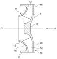
도 1에 도시한 실시 형태에서는, 임펠러(1)는, 원심 임펠러이다. 보다 구체적으로는, 임펠러(1)는, 원반상의 주판(10)과, 주판(10)에 대향하여 배치된 측판(11)과, 주판(10)과 측판(11) 사이에 배치된 복수의 날개(12)를 구비하고 있다. 원심 임펠러로서의 임펠러(1)를 구비하는 모터 펌프 MP는, 축류 펌프나 사류 펌프 등의 펌프와 비교하여, 양압 특성이 우수하여, 높은 압력을 발생시킬 수 있다. 또한, 본 실시 형태에 있어서의 모터 펌프 MP는, 그 내부에서 발생한 압력차를 이용하여, 임펠러(1)의 회전 안정성에 공헌할 수 있다.In the embodiment shown in FIG. 1, the
측판(11)은, 그 중앙 부분에 형성된 흡입부(15)와, 흡입부(15)에 접속된 본체부(16)를 구비하고 있다. 흡입부(15)는, 모터 펌프 MP의 중심선 CL 방향으로 연장되어 있고, 본체부(16)는, 중심선 CL에 대하여 경사지는 방향(보다 구체적으로는, 수직 방향)으로 연장되어 있다. 중심선 CL은, 모터 펌프 MP의 운전에 의해 흐르는 액체(취급액)의 흐름 방향과 평행이다.The
도 1에 도시한 바와 같이, 측판(11)은, 측판(11)의 외연부(11a)(보다 구체적으로는, 본체부(16)의 단부)로부터 흡입부(15)를 향하여 연장되는 환상의 돌기부(17)를 구비하고 있다. 도 1에 도시한 실시 형태에서는, 본체부(16) 및 돌기부(17)는 일체적으로 구성되어 있지만, 돌기부(17)는 본체부(16)와는 별도의 부재여도 된다.As shown in FIG. 1, the
회전자(2)는, 돌기부(17)의 외경보다도 큰 내경을 갖고 있고, 돌기부(17)의 외주면(17a)에 고정되어 있다. 고정자(3)는, 회전자(2)를 둘러싸도록 배치되어 있고, 고정자 케이싱(20)에 수용되어 있다. 고정자 케이싱(20)은, 임펠러(1)의 반경 방향 외측에 배치되어 있다.The
모터 펌프 MP는, 고정자 케이싱(20)의 양측에 배치된 흡입 케이싱(21) 및 토출 케이싱(22)을 구비하고 있다. 흡입 케이싱(21)은, 임펠러(1)의 흡입측에 배치되어 있고, 토출 케이싱(22)은, 임펠러(1)의 토출측에 배치되어 있다. 임펠러(1), 회전자(2), 및 베어링(5)은, 고정자 케이싱(20)의 반경 방향 내측에 배치되어 있고, 흡입 케이싱(21)과 토출 케이싱(22) 사이에 배치되어 있다.The motor pump MP has a suction casing (21) and a discharge casing (22) disposed on both sides of the stator casing (20). The
흡입 케이싱(21)은, 그 중앙 부분에 흡입구(21a)를 갖고 있다. 토출 케이싱(22)은, 그 중앙 부분에 토출구(22a)를 갖고 있다. 이들 흡입구(21a) 및 토출구(22a)는, 중심선 CL을 따라서 일직선으로 나란히 배치되어 있다. 따라서, 흡입구(21a)로부터 흡입되고, 토출구(22a)로부터 토출되는 취급액은, 일직선으로 흐른다.The
도 1에 도시한 바와 같이, 작업자는, 고정자 케이싱(20)을 흡입 케이싱(21)과 토출 케이싱(22) 사이에 둔 상태에서, 관통 볼트(25)를 흡입 케이싱(21) 및 토출 케이싱(22)에 삽입하여, 관통 볼트(25)를 체결한다. 이와 같이 하여, 모터 펌프 MP는 조립된다.As shown in FIG. 1, the operator places the
모터 펌프 MP가 운전되면, 취급액은, 흡입 케이싱(21)의 흡입구(21a)로부터 흡입된다(도 1의 흑색선 화살표 참조). 임펠러(1)는, 그 회전에 의해, 취급액을 승압하고, 취급액은, 임펠러(1)의 내부에 있어서, 중심선 CL과 수직 방향(즉, 원심 방향)으로 흐른다. 임펠러(1)의 외부에 토출된 취급액은, 고정자 케이싱(20)의 내주면(20a)에 충돌하여, 취급액의 방향이 전환된다. 그 후, 취급액은, 임펠러(1)의 배면(보다 구체적으로는, 주판(10))과 토출 케이싱(22) 사이의 간극을 통해, 토출구(22a)로부터 토출된다.When the motor pump MP is operated, the handling liquid is sucked in from the
도 1에 도시한 바와 같이, 모터 펌프 MP는, 임펠러(1)의 배면 측에 배치된 복귀 블레이드(30)를 구비하고 있다. 도 1에 도시한 실시 형태에서는, 나선상으로 연장되는 복수의 복귀 블레이드(30)가 마련되어 있다. 이들 복수의 복귀 블레이드(30)는, 토출 케이싱(22)에 고정되어 있고, 임펠러(1)의 주판(10)에 대향하고 있다. 복귀 블레이드(30)를 마련함으로써, 임펠러(1)로부터 토출된 취급액은, 원활하게 토출구(22a)로 안내된다. 복귀 블레이드(30)는, 임펠러(1)로부터 토출된 취급액의, 속도 에너지로부터 압력 에너지로의 변환에 기여한다.As shown in FIG. 1, the motor pump MP is provided with a
도 1에 도시한 실시 형태에서는, 모터 펌프 MP는, 그 영역이, 흡입측 영역 Ra와, 토출측 영역 Rb와, 흡입측 영역 Ra와 토출측 영역 Rb 사이의 중간 영역 Rc로 구획된다. 흡입측 영역 Ra는, 흡입 케이싱(21)(보다 구체적으로는, 흡입 케이싱(21)의 흡입구(21a))과 임펠러(1)(보다 구체적으로는, 임펠러(1)의 측판(11)) 사이의 영역이다. 토출측 영역 Rb는, 토출 케이싱(22)(보다 구체적으로는, 토출 케이싱(22)의 토출구(22a))과 임펠러(1)(보다 구체적으로는, 임펠러(1)의 주판(10)) 사이의 영역이다. 중간 영역 Rc에는, 복수의 날개(12)가 배치되어 있다.In the embodiment shown in FIG. 1, the motor pump MP is divided into a suction side region Ra, a discharge side region Rb, and an intermediate region Rc between the suction side region Ra and the discharge side region Rb. The suction side area Ra is between the suction casing 21 (more specifically, the
회전자(2) 및 베어링(5)은, 임펠러(1)의 흡입측 영역 Ra에 배치되어 있다. 본 실시 형태에서는, 임펠러(1)는, 흡입측 영역 Ra로부터 토출측 영역 Rb를 향하여 확대되는 테이퍼 형상을 갖는 측판(11)을 구비하고 있다. 따라서, 임펠러(1)의 흡입측 영역 Ra에는, 공간(데드 스페이스)이 형성된다. 본 실시 형태에 따르면, 회전자(2) 및 베어링(5)을 흡입측 영역 Ra에 배치함으로써, 모터 펌프 MP는 데드 스페이스를 유효하게 활용한 구조를 가질 수 있고, 결과적으로, 콤팩트한 구조를 가질 수 있다.The
베어링(5)은, 측판(11)의 돌기부(17)에 장착된 회전측 베어링체(6)와, 흡입 케이싱(21)에 장착된 고정측 베어링체(7)를 구비하고 있다. 고정측 베어링체(7)는, 회전측 베어링체(6)의 흡입측에 배치되어 있다. 회전측 베어링체(6)는, 임펠러(1)의 회전과 함께 회전하는 회전 부재이며, 고정측 베어링체(7)는, 임펠러(1)가 회전해도 회전하지 않는 정지 부재이다.The
회전측 베어링체(6)는, 돌기부(17)의 내경보다도 작은 외경을 갖는 원통부(6a)와, 원통부(6a)로부터 외측으로 돌출된 플랜지부(6b)를 갖고 있다. 따라서, 회전측 베어링체(6)의 단면은 L자 형상을 갖고 있다. 돌기부(17)의 내주면(17b)과 원통부(6a) 사이에는, 시일 부재(예를 들어, O링)(31)가 배치되어 있다.The rotation-
회전측 베어링체(6)는, 그 원통부(6a)에 시일 부재(31)가 장착된 상태에서, 임펠러(1)의 돌기부(17)에 장착된다. 회전측 베어링체(6)의 장착에 의해, 회전자(2)는 회전측 베어링체(6)의 플랜지부(6b)에 인접하여 배치된다.The rotation-
고정측 베어링체(7)는, 회전측 베어링체(6)의 원통부(6a)에 대향하여 배치된 원통부(7a)와, 회전측 베어링체(6)의 플랜지부(6b)에 대향하여 배치된 플랜지부(7b)를 구비하고 있다. 고정측 베어링체(7)의 단면은, 회전측 베어링체(6)의 단면과 마찬가지로, L자 형상을 갖고 있다. 고정측 베어링체(7)의 원통부(7a)와 흡입 케이싱(21) 사이에는, 시일 부재(32, 33)가 배치되어 있다. 본 실시 형태에서는, 2개의 시일 부재(32, 33)가 배치되어 있지만, 시일 부재의 수는, 본 실시 형태에 한정되지는 않는다.The fixed
도 2는 회전측 베어링체와 고정측 베어링체 사이의 간극을 통과하는 취급액의 흐름을 도시하는 도면이다. 취급액은, 임펠러(1)의 회전에 의해 승압되기 때문에, 토출측 영역 Rb에 있어서의 취급액의 압력은, 흡입측 영역 Ra에 있어서의 취급액의 압력보다도 크다. 따라서, 임펠러(1)로부터 토출된 취급액의 일부는, 흡입측 영역 Ra로 역류한다(도 2의 흑색선 화살표 참조).Fig. 2 is a diagram showing the flow of handling liquid passing through a gap between the rotating side bearing body and the stationary side bearing body. Since the pressure of the handling liquid is increased by the rotation of the
보다 구체적으로는, 취급액의 일부는, 고정자 케이싱(20)과 회전자(2) 사이의 간극을 통과하여, 회전측 베어링체(6)의 플랜지부(6b)와 고정측 베어링체(7)의 플랜지부(7b) 사이의 간극에 유입된다.More specifically, a part of the handling liquid passes through the gap between the
도 3은 고정측 베어링체의 플랜지부에 형성된 복수의 홈의 일 실시 형태를 도시하는 도면이다. 도 3에 도시한 바와 같이, 고정측 베어링체(7)는, 플랜지부(7b)에 형성된 복수의 홈(40)을 갖고 있다. 이들 복수의 홈(40)은, 플랜지부(7b)의, 회전측 베어링체(6)의 플랜지부(6b)와의 대향면에 형성되어 있다. 복수의 홈(40)은, 취급액의 동압을 플랜지부(7b)와 플랜지부(6b) 사이의 간극에 발생시키기 위해 형성되어 있다. 본 실시 형태에서는, 복수의 홈(40)은, 나선상으로 연장되는 나선 홈이다. 일 실시 형태에서는, 복수의 홈(40)은, 방사상으로 연장되는 방사 홈이어도 된다. 복수의 홈(40)을 형성함으로써, 베어링(5)은, 임펠러(1)의 스러스트 하중을 비접촉으로 지지할 수 있다.FIG. 3 is a diagram showing one embodiment of a plurality of grooves formed in the flange portion of the fixed side bearing body. As shown in FIG. 3, the fixed
도 3에 도시한 실시 형태에서는, 복수의 홈(40)은, 플랜지부(7b)에 형성되어 있지만, 일 실시 형태에서는, 복수의 홈(40)은, 회전측 베어링체(6)의 플랜지부(6b)에 형성되어도 된다. 이와 같은 형성에 의해서도, 베어링(5)은, 임펠러(1)의 스러스트 하중을 비접촉으로 지지할 수 있다.In the embodiment shown in FIG. 3, the plurality of
도 4a는 고정측 베어링체의 원통부에 형성된 복수의 홈의 일 실시 형태를 도시하는 도면이다. 도 4a는 중심선 CL 방향으로부터 보았을 때의 복수의 홈(41)을 도시하고 있다. 고정측 베어링체(7)는, 원통부(7a)의 원주 방향을 따라서, 원통부(7a)에 형성된 복수의 홈(41)을 가져도 된다. 도 4a에 도시한 실시 형태에서는, 복수의 홈(41)은, 등간격으로 배치되어 있지만, 부등 간격으로 배치되어도 된다.FIG. 4A is a diagram showing one embodiment of a plurality of grooves formed in the cylindrical portion of the fixed-side bearing body. FIG. 4A shows a plurality of
이들 복수의 홈(41)은, 원통부(7a)의, 회전측 베어링체(6)의 원통부(6a)와의 대향면에 형성되어 있고, 원통부(7a)(즉, 중심선 CL 방향)와 평행하게 연장되어 있다. 도 4a에 도시한 실시 형태에서는, 복수의 홈(41)의 각각은, 중심선 CL 방향으로부터 보았을 때, 원호상으로 오목하게 들어간 형상을 갖고 있다. 복수의 홈(41)의 형상은, 본 실시 형태에 한정되지는 않는다. 일 실시 형태에서는, 복수의 홈(41)의 각각은, 중심선 CL 방향으로부터 보았을 때, 오목 형상으로 오목하게 들어간 형상을 가져도 된다.These plurality of
도 4b 및 도 4c는 고정측 베어링체의 원통부에 형성된 홈의 다른 실시 형태를 도시하는 도면이다. 도 4b 및 도 4c에 도시한 바와 같이, 고정측 베어링체(7)는, 원통부(7a)의 원주 방향을 따라서, 원통부(7a)에 형성된 환상의 홈(42)을 갖고 있다. 홈(42)은, 원통부(7a)의 일부에 형성되어 있고, 중심선 CL 방향과 수직인 방향으로부터 보았을 때, 오목 형상을 갖고 있다(도 4b 및 도 4c 참조). 홈(42)의, 중심선 CL 방향에 있어서의 양단(42a, 42a)에는, 원통부(7a)가 존재하고 있다. 이와 같은 구조에 의해, 임펠러(1)에 레이디얼 하중이 작용해도, 고정측 베어링체(7)(보다 구체적으로는, 원통부(7a))는, 회전측 베어링체(6)를 통해 임펠러(1)를 확실하게 지지할 수 있다. 또한, 중심선 CL 방향에 있어서의 홈(42)의 길이는, 특별히 한정되지는 않는다. 도 4b 및 도 4c에 도시한 실시 형태에서는, 고정측 베어링체(7)는, 단일의 홈(42)을 갖고 있지만, 일 실시 형태에서는, 고정측 베어링체(7)는, 중심선 CL 방향을 따라서 배치된 복수의 홈(42)을 가져도 된다.4B and 4C are diagrams showing another embodiment of a groove formed in the cylindrical portion of the fixed side bearing body. As shown in FIGS. 4B and 4C , the fixed-
플랜지부(6b)와 플랜지부(7b) 사이의 간극을 통과한 취급액은, 원통부(6a)와 원통부(7a) 사이의 간극에 유입된다. 임펠러(1)와 함께 회전측 베어링체(6)가 회전하면, 이 간극을 흐르는 취급액에는, 점성 저항이 발생해 버린다. 이 점성 저항은, 모터 펌프 MP의 운전 효율에 악영향을 미칠 우려가 있다.The handling liquid that has passed through the gap between the
상술한 실시 형태에 나타내는 바와 같이, 복수의 홈(41)(또는 홈(42))을 형성함으로써, 원통부(6a)와 원통부(7a) 사이의 간극에 형성된 협소 영역의 크기는 저감된다. 따라서, 취급액에 발생하는 점성 저항을 저감할 수 있다. 또한, 복수의 홈(41)(또는 홈(42))을 형성함으로써, 취급액의 동압이 발생하여, 베어링(5)은, 임펠러(1)의 레이디얼 하중을 비접촉으로 지지할 수 있다. 플랜지부(6b)와 플랜지부(7b) 사이에 형성된 협소 영역의 크기의 저감에 의해 점성 저항을 저감하는 효과는, 복수의 홈(40)(도 3 참조)을 마련함으로써도 발휘할 수 있다.As shown in the above-described embodiment, by forming a plurality of grooves 41 (or grooves 42), the size of the narrow region formed in the gap between the
도 4a 내지 도 4c에 도시한 실시 형태에서는, 홈(41, 42)은, 원통부(7a)에 형성되어 있지만, 일 실시 형태에서는, 홈(41, 42)은, 회전측 베어링체(6)의 원통부(6a)에 형성되어도 된다. 이와 같은 형성에 의해서도, 베어링(5)은, 임펠러(1)의 레이디얼 하중을 비접촉으로 지지할 수 있다.In the embodiment shown in FIGS. 4A to 4C, the
도 2에 도시한 바와 같이, 회전측 베어링체(6)의 원통부(6a)와 고정측 베어링체(7)의 원통부(7a) 사이의 간극을 통과한 취급액은, 임펠러(1)의 측판(11)과 흡입 케이싱(21) 사이의 간극을 통과하여, 모터 펌프 MP의 흡입측으로 되돌려진다. 본 실시 형태에서는, 베어링(5)은, 취급액의 누설 흐름의 진로 상에 배치되어 있다. 이와 같은 구성에 의해, 취급액의 일부는, 회전측 베어링체(6)와 고정측 베어링체(7) 사이의 미소한 간극에 유입되고, 결과적으로, 모터 펌프 MP는 취급액의 누설을 억제할 수 있다.As shown in FIG. 2, the handling fluid that has passed through the gap between the
상술한 바와 같이, 토출측 영역 Rb에 있어서의 취급액의 압력은, 흡입측 영역 Ra에 있어서의 취급액의 압력보다도 크다. 따라서, 임펠러(1)에는, 토출 케이싱(22)의 토출구(22a)로부터 흡입 케이싱(21)의 흡입구(21a)를 향하여 스러스트 하중이 작용한다(도 1의 백색 바탕 화살표 참조). 본 실시 형태에 관한 모터 펌프 MP는, 스러스트 하중을 저감하는 구조를 갖고 있다.As described above, the pressure of the handling liquid in the discharge side area Rb is greater than the pressure of the handling liquid in the suction side area Ra. Therefore, a thrust load acts on the
도 5a는 임펠러의 배면에 마련된 스러스트 하중 저감 구조의 일 실시 형태를 도시하는 도면이다. 도 5b는 도 5a를 A선 화살표로부터 본 도면이다. 도 5a 및 도 5b에 도시한 바와 같이, 모터 펌프 MP는, 임펠러(1)의 배면(보다 구체적으로는, 주판(10))에 마련된 스러스트 하중 저감 구조(45)를 구비하고 있다. 도 5a 및 도 5b에 도시한 실시 형태에서는, 스러스트 하중 저감 구조(45)는, 주판(10)에 설치된, 나선상으로 연장되는 복수의 이면 블레이드(46)이다. 이들 복수의 이면 블레이드(46)는, 임펠러(1)의 회전에 의해, 스러스트 하중과는 반대 방향의 하중을 발생시킬 수 있다. 결과적으로, 스러스트 하중 저감 구조(45)는, 모터 펌프 MP에 발생하는 스러스트 하중을 저감할 수 있다.FIG. 5A is a diagram showing one embodiment of a thrust load reduction structure provided on the rear surface of the impeller. FIG. 5B is a view of FIG. 5A viewed from arrow line A. As shown in FIGS. 5A and 5B, the motor pump MP is provided with a thrust
도 6은 스러스트 하중 저감 구조의 다른 실시 형태를 도시하는 도면이다. 도 6에 도시한 바와 같이, 스러스트 하중 저감 구조(45)는, 임펠러(1)(보다 구체적으로는, 주판(10))의 주위 방향을 따라서 형성된, 임펠러(1)의 중심측을 향하여 연장되는 복수의 노치 구조여도 된다. 도 6에 도시한 실시 형태에서는, 임펠러(1)의 주판(10)에는, 복수의 노치(47)가 형성되어 있다. 복수의 노치(47)를 형성함으로써, 취급액의, 주판(10)과의 접촉 면적은 저감된다. 결과적으로, 스러스트 하중 저감 구조(45)는, 모터 펌프 MP에 발생하는 스러스트 하중을 저감할 수 있다. 도시하지 않지만, 도 5에 도시한 실시 형태와 도 6에 도시한 실시 형태는 조합되어도 된다.6 is a diagram showing another embodiment of a thrust load reduction structure. As shown in FIG. 6, the thrust
본 실시 형태에서는, 임펠러(1)는, 항상, 토출측으로부터 흡입측을 향하여, 스러스트 하중을 받는다. 또한, 베어링(5)은, 회전력을 발생시키는 임펠러(1)를 지지하고 있다. 따라서, 임펠러(1) 자체의 평행은 유지되어, 임펠러(1)의 덜걱거림을 억제할 수 있다. 결과적으로, 단일의 베어링(5)을 흡입측 영역 Ra에 배치하는 것만의 구조(즉, 단일 베어링 구조)로, 모터 펌프 MP는, 그 운전을 안정적으로 계속할 수 있다.In this embodiment, the
일 실시 형태에서는, 임펠러(1) 및 베어링(5) 중, 적어도 1개는, 경량 재질로 구성되어도 된다. 경량 재질로서, 수지 또는 비중이 작은 금속(예를 들어, 알루미늄 합금, 마그네슘 합금, 티타늄 합금 등)을 들 수 있다. 이와 같은 구조에 의해, 모터 펌프 MP 자체의 중량을 경감할 수 있고, 나아가, 베어링(5)(및 임펠러(1))의 한층 더한 콤팩트화를 실현할 수 있다. 또한, 임펠러(1) 및 베어링(5) 등의, 액체에 접촉하는 부재(즉, 접액 부재)의 재질은, 특별히 한정되지는 않고, 액질에 따라서, 적절히, 임의의 재질로 변경 가능하다.In one embodiment, at least one of the
또한 본 실시 형태에서는, 복수의 복귀 블레이드(30)(도 1 참조)는, 임펠러(1)에 발생하는 레이디얼 하중을 저감할 수 있다. 복수의 복귀 블레이드(30)는, 토출구(22a)의 주위 방향을 따라서 등간격으로 배치되어 있다. 이와 같은 배치에 의해, 레이디얼 하중은 균등하게 분배되고, 결과적으로, 임펠러(1)에 발생하는 레이디얼 하중은 경감된다.Additionally, in this embodiment, the plurality of return blades 30 (see FIG. 1) can reduce the radial load generated on the
본 실시 형태에서는, 모터 펌프 MP는, 영구 자석형 모터를 구비하고 있다. 따라서, 모터 펌프 MP의 시동 시에는, 자력에 기인하는 반발력을 회전력으로 변환하기 위한 일정한 하중이 베어링(5)에 작용한다. 이 하중은 회전자(2)에 발생하는 힘이며, 베어링(5)은 이 하중을 지지한다.In this embodiment, the motor pump MP is equipped with a permanent magnet type motor. Therefore, when the motor pump MP is started, a certain load is applied to the
도 7a 및 도 7b는, 고정자에 대하여 어긋나게 하여 배치된 회전자를 도시하는 도면이다. 도 7a에 도시한 바와 같이, 고정자(3)에 대하여, 회전자(2)를 토출 측으로 어긋나게 하여 배치한 경우, 임펠러(1)는, 회전자(2)와 고정자(3) 사이에 발생하는 자력의 영향에 의해, 회전측 베어링체(6)가 고정측 베어링체(7)에 근접하는 방향으로 작용하는 힘을 받는다(도 7a의 화살표 참조). 이와 같은 배치에 의해, 고정측 베어링체(7)에 작용하는 회전측 베어링체(6)의 스러스트 하중을 조정(증가)할 수 있다.7A and 7B are diagrams showing a rotor disposed offset with respect to a stator. As shown in FIG. 7A, when the
도 7b에 도시한 바와 같이, 고정자(3)에 대하여, 회전자(2)를 흡입측으로 어긋나게 하여 배치한 경우, 임펠러(1)는, 회전자(2)와 고정자(3) 사이에 발생하는 자력의 영향에 의해, 회전측 베어링체(6)가 고정측 베어링체(7)로부터 이격되는 방향으로 작용하는 힘을 받는다(도 7b 참조). 이와 같은 배치에 의해, 고정측 베어링체(7)에 작용하는 회전측 베어링체(6)의 스러스트 하중을 조정(저감)할 수 있다.As shown in FIG. 7B, when the
도 8은 테이퍼 구조를 갖는 베어링의 일 실시 형태를 도시하는 도면이다. 도 8에 도시한 실시 형태에서는, 베어링(5)은, 회전측 베어링체(6)와 고정측 베어링체(7) 사이의 간극이 흡입측으로부터 토출측을 향하여 중심선 CL(즉, 임펠러(1)의 중심 부분)에 근접하는 방향으로 연장되는 테이퍼 구조를 갖고 있다. 도 8에 도시한 바와 같이, 회전측 베어링체(6) 및 고정측 베어링체(7)는, 서로 대향하는 경사면(50, 51)을 각각 갖고 있다. 이와 같은 구성에 의해, 베어링(5)은, 회전측 베어링체(6) 및 고정측 베어링체(7)에 작용하는 레이디얼 하중 및 스러스트 하중을 경사면(50, 51)에 집약할 수 있어, 베어링(5)은, 심플한 구조를 가질 수 있다.Figure 8 is a diagram showing one embodiment of a bearing with a tapered structure. In the embodiment shown in FIG. 8, the
도 9는 테이퍼 구조를 갖는 베어링의 다른 실시 형태를 도시하는 도면이다. 도 9에 도시한 실시 형태에서는, 베어링(5)은, 회전측 베어링체(6)와 고정측 베어링체(7) 사이의 간극이 흡입측으로부터 토출측을 향하여 중심선 CL(즉, 임펠러(1)의 중심 부분)로부터 이격되는 방향으로 연장되는 테이퍼 구조를 갖고 있다. 도 9에 도시한 바와 같이, 회전측 베어링체(6) 및 고정측 베어링체(7)는, 서로 대향하는 경사면(53, 54)을 각각 갖고 있다.9 is a diagram showing another embodiment of a bearing with a tapered structure. In the embodiment shown in FIG. 9, the
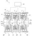
도 10은 복수의 모터 펌프를 구비하는 펌프 유닛을 도시하는 도면이다. 도 10에 도시한 바와 같이, 펌프 유닛 PU는, 직렬적으로 배치된 복수의 모터 펌프 MP와, 복수의 모터 펌프 MP의 각각의 동작을 제어하는 인버터(60)를 구비해도 된다. 도 10에 도시한 실시 형태에서는, 복수의 모터 펌프 MP의 각각은, 상술한 실시 형태에서 나타낸 구조와 동일한 구조를 갖고 있다. 따라서, 모터 펌프 MP의 상세한 설명을 생략한다.Figure 10 is a diagram showing a pump unit including a plurality of motor pumps. As shown in FIG. 10, the pump unit PU may be provided with a plurality of motor pumps MP arranged in series and an
도 10에 도시한 실시 형태에서는, 펌프 유닛 PU는, 3개의 모터 펌프 MP를 구비하고 있지만, 모터 펌프 MP의 수는 본 실시 형태에 한정되지는 않는다. 상술한 바와 같이, 펌프 유닛 PU의 흡입구(21a) 및 토출구(22a)는, 중심선 CL을 따라서 일직선으로 나란히 배치되어 있다. 따라서, 복수의 모터 펌프 MP를 연속적으로 일직선 상에 배치할 수 있어, 펌프 유닛 PU는, 용이하게 다단의 모터 펌프 구조를 가질 수 있다.In the embodiment shown in FIG. 10, the pump unit PU is provided with three motor pumps MP, but the number of motor pumps MP is not limited to this embodiment. As described above, the
도 10에 도시한 바와 같이, 1단째의 임펠러(1A)에 인접하여 배치된 흡입 케이싱(21)과, 3단째의 임펠러(1C)에 인접하여 배치된 토출 케이싱(22) 사이에는, 2개의 중간 케이싱(61)이 배치되어 있다. 이들 중간 케이싱(61, 61) 사이에는, 2단째의 임펠러(1B)가 배치되어 있다. 중간 케이싱(61, 61)의 각각은, 흡입 케이싱(21)과 공통의(즉, 유사) 구조를 갖고 있다. 작업자는, 흡입 케이싱(21)과 토출 케이싱(22) 사이에 중간 케이싱(61, 61)을 둔 상태에서, 관통 볼트(25)를 이들 흡입 케이싱(21), 중간 케이싱(61, 61), 및 토출 케이싱(22)에 삽입하여, 체결함으로써, 펌프 유닛을 조립할 수 있다.As shown in FIG. 10, between the
도 10에 도시한 바와 같이, 복수의 모터 펌프 MP의 고정자(3)에는, 1대의 인버터(60)가 접속되어 있다. 인버터(60)는, 복수의 모터 펌프 MP의 각각을 독립적으로 제어할 수 있다. 따라서, 작업자는, 펌프 유닛의 운전 조건에 따라서, 적어도 1대의 모터 펌프 MP를 임의의 타이밍에 운전할 수 있다.As shown in Fig. 10, one
도 11 및 도 12는 펌프 유닛의 다른 실시 형태를 도시하는 도면이다. 도 11 및 도 12에 도시한 실시 형태에서는, 펌프 유닛 PU는, 병렬적으로 배치된 복수의 모터 펌프 MP를 구비하고 있다. 도 11에서는, 간략적으로 도시되어 있지만, 이들 복수의 모터 펌프 MP의 각각은, 배관(65)의 내측에 설치되어 있다. 도 11에서는, 4대의 모터 펌프 MP가 마련되어 있지만, 모터 펌프 MP의 수는 본 실시 형태에 한정되지는 않는다. 도 12에 도시한 바와 같이, 3대의 모터 펌프 MP가 마련되어도 된다.11 and 12 are views showing another embodiment of the pump unit. In the embodiment shown in FIGS. 11 and 12, the pump unit PU is provided with a plurality of motor pumps MP arranged in parallel. Although shown briefly in FIG. 11 , each of these plurality of motor pumps MP is installed inside the
도 13a는 비교예로서의 모터 펌프를 도시하는 도면이다. 도 13b 및 도 13c는, 모터 펌프의 다른 실시 형태를 도시하는 도면이다. 도 13a에 도시한 바와 같이, 비교예로서의 모터 펌프는, 회전축 RS를 구비하고 있지만, 본 실시 형태에 관한 모터 펌프 MP는, 회전축 RS를 갖고 있지 않다. 그 대신에, 임펠러(1)는, 그 중심 부분에 배치된, 둥그스름하게 된 볼록부(70)를 구비하고 있다.Fig. 13A is a diagram showing a motor pump as a comparative example. 13B and 13C are diagrams showing another embodiment of a motor pump. As shown in FIG. 13A, the motor pump as a comparative example has a rotating shaft RS, but the motor pump MP according to the present embodiment does not have a rotating shaft RS. Instead, the
도 13b에 도시한 실시 형태에서는, 임펠러(1)는, 제1 곡률 반경을 갖는 볼록부(70A)를 갖고 있고, 도 13c에 도시한 실시 형태에서는, 임펠러(1)는, 제1 곡률 반경과는 다른 제2 곡률 반경을 갖는 볼록부(70B)를 갖고 있다. 이하, 볼록부(70A, 70B)를 구별하지 않고, 간단히 볼록부(70)라 칭하는 경우가 있다.In the embodiment shown in FIG. 13B, the
볼록부(70)는, 주판(10)의 중심 부분에 배치되어 있고, 주판(10)과 일체적으로 구성되어 있다. 일 실시 형태에서는, 볼록부(70)는 주판(10)과는 다른 부재여도 된다. 이 경우, 모터 펌프의 운전 조건에 따라서, 곡률 반경이 다른 볼록부(70)를 교환해도 된다.The convex portion 70 is disposed at the center of the
볼록부(70)의 선단부(71)은, 매끄러운 볼록 형상을 갖고 있고, 임펠러(1)에 유입되는 취급액은, 볼록부(70)의 선단부(71)에 접촉한다. 볼록부(70)를 마련함으로써, 취급액은, 그 흐름이 저해되지 않고, 원활하게, 또한 효율적으로, 날개(12)로 안내된다. 한편, 비교예로서의 모터 펌프에서는, 회전축 RS는, 너트 Nt에 의해 임펠러에 고정되어 있기 때문에, 취급액의 흐름은, 너트 Nt(및 회전축 RS)에 의해 저해되어 버릴 우려가 있다.The tip 71 of the convex part 70 has a smooth convex shape, and the handling liquid flowing into the
도 13b에 도시한 볼록부(70A)는, 도 13c에 도시한 볼록부(70B)의 곡률 반경보다도 큰 곡률 반경을 갖고 있다. 볼록부(70)의 곡률 반경을 크게 함으로써, 볼록부(70)와 측판(11) 사이의 거리는 작아진다. 반대로, 볼록부(70)의 곡률 반경을 작게 함으로써, 볼록부(70)와 측판(11) 사이의 거리는 커진다. 이와 같이, 볼록부(70)의 곡률 반경을 변경함으로써, 취급액의, 임펠러(1)의 유로의 크기를 조정할 수 있다. 도 13c에 도시한 임펠러(1)의 유로는, 도 13b에 도시한 임펠러(1)의 유로보다도 크다.The convex portion 70A shown in FIG. 13B has a larger radius of curvature than the radius of curvature of the convex portion 70B shown in FIG. 13C. By increasing the radius of curvature of the convex portion 70, the distance between the convex portion 70 and the
본 실시 형태에 따르면, 모터 펌프 MP는, 회전축을 갖고 있지 않기 때문에, 부품 개수를 삭감할 수 있어, 유로의 크기의 조정도 가능하다. 또한, 회전축을 마련할 필요는 없기 때문에, 임펠러(1)는, 콤팩트한 사이즈를 가질 수 있다. 결과적으로, 모터 펌프 MP의 전체는, 콤팩트한 사이즈를 가질 수 있다.According to this embodiment, since the motor pump MP does not have a rotating shaft, the number of parts can be reduced, and the size of the flow path can also be adjusted. Additionally, since there is no need to provide a rotating shaft, the
모터 펌프는, 그 운전에 의해, 임펠러(1)를 고속으로 회전시킨다. 만약, 임펠러(1)의 무게 중심 위치가 어긋나 있으면, 임펠러(1)는, 편심된 상태에서 고속으로 회전해 버린다. 결과적으로, 소음이 발생할 우려가 있고, 최악의 경우, 모터 펌프가 고장나 버릴 우려가 있다.The motor pump rotates the
따라서, 작업자는, 임펠러(1)의 무게 중심 위치를 원하는 위치로 결정하는 밸런스(다이내믹 밸런스) 조정 방법을 실행한다. 도 13a에 도시한 바와 같이, 임펠러에 회전축 RS가 설치되어 있는 경우, 회전축 RS를 시험기에 설치하여, 회전축 RS와 함께 임펠러를 회전할 필요가 있다. 본 실시 형태에서는, 임펠러(1)에는, 회전축 RS가 설치되어 있지 않기 때문에, 작업자는, 이하에서 설명하는 밸런스 조정 방법을 실행하는 것이 가능하다.Therefore, the operator performs a balance (dynamic balance) adjustment method to determine the position of the center of gravity of the
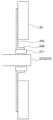
도 14 내지 도 18은 밸런스 조정 방법의 일 실시 형태를 도시하는 도면이다. 도 14에 도시한 바와 같이, 먼저, 작업자는, 임펠러(1)의 중심(보다 구체적으로는, 주판(10))에 관통 구멍(10a)을 형성하는 공정을 실행한다. 그 후, 도 15에 도시한 바와 같이, 작업자는, 밸런스 조정 지그(75)의 축체(76)를 관통 구멍(10a)에 삽입한다. 밸런스 조정 지그(75)의 축체(76)는, 회전축에 상당한다.14 to 18 are diagrams showing one embodiment of a balance adjustment method. As shown in FIG. 14, first, the operator performs a process of forming a through hole 10a in the center of the impeller 1 (more specifically, the main plate 10). After that, as shown in FIG. 15, the operator inserts the shaft body 76 of the balance adjustment jig 75 into the through hole 10a. The shaft body 76 of the balance adjustment jig 75 corresponds to a rotation shaft.
그 후, 도 16에 도시한 바와 같이, 작업자는, 임펠러(1)의 배면측에 고정체(77)를 배치하고, 축체(76)를 고정체(77)에 체결한다. 이 상태에서, 작업자는, 밸런스 조정 지그(75)와 함께 임펠러(1)를 회전시킨 상태에서, 임펠러(1)의 무게 중심 위치를 결정하고, 무게 중심 위치를 조정하는 공정을 실행한다. 이와 같이, 밸런스 조정 지그(75)는, 임펠러(1)의 중심을 지지하는 구조를 갖고 있다. 따라서, 밸런스 조정 지그(75)는, 센터 서포트 조정 지그라 불려도 된다.Afterwards, as shown in FIG. 16, the operator places the fixture 77 on the rear side of the
작업자는, 임펠러(1)의 무게 중심 위치를 원하는 위치로 결정한 후, 밸런스 조정 지그(75)의 축체(76)를 빼내고, 그 후, 센터 캡(80)을 관통 구멍(10a)에 삽입하여, 관통 구멍(10a)을 폐색한다(도 17 및 도 18 참조). 센터 캡(80)은, 도 13b 및 도 13c에 도시한 실시 형태에 관한 볼록부(70)와 마찬가지로, 둥그스름하게 된 형상을 갖고 있다. 따라서, 취급액은, 그 흐름이 저해되지 않고, 원활하게, 또한 효율적으로, 날개(12)로 안내된다.After determining the position of the center of gravity of the
도 19는 밸런스 조정 지그의 다른 실시 형태를 도시하는 도면이다. 도 18에 도시한 실시 형태에서는, 밸런스 조정 지그(75)는, 임펠러(1)의 중심을 지지하는 구조를 갖고 있다. 도 19에 도시한 실시 형태에서는, 밸런스 조정 지그(85)는, 베어링(5)의 회전측 베어링체(6)를 지지하는 서포터(86)와, 서포터(86)에 고정된 축부(87)를 구비하고 있다. 이와 같이, 밸런스 조정 지그(85)는, 임펠러(1)의 단부를 지지하는 구조를 갖고 있다. 따라서, 밸런스 조정 지그(85)는, 에지 서포트 조정 지그라 불려도 된다.Fig. 19 is a diagram showing another embodiment of the balance adjustment jig. In the embodiment shown in FIG. 18, the balance adjustment jig 75 has a structure that supports the center of the
서포터(86)는, 회전측 베어링체(6)의 내경보다도 작은 외경을 갖는 환상 형상을 갖고 있고, 서포터(86)를 회전측 베어링체(6)에 삽입함으로써, 밸런스 조정 지그(85)는, 회전측 베어링체(6)를 통해, 임펠러(1)를 지지한다. 이 상태에서, 작업자는, 밸런스 조정 지그(85)와 함께 임펠러(1)를 회전시키는 공정을 실행한다. 그 후, 작업자는, 임펠러(1)를 회전시킨 상태에서, 임펠러(1)의 무게 중심 위치를 결정하고, 무게 중심 위치를 조정하는 공정을 실행한다.The supporter 86 has an annular shape with an outer diameter smaller than the inner diameter of the rotation
도 19에 도시한 실시 형태에 따르면, 작업자는, 관통 구멍(10a)을 형성할 필요는 없다. 도 19에 도시한 실시 형태에 있어서도, 임펠러(1)는, 그 중심 위치에 형성된 볼록부(70)를 가져도 된다(도 13a 및 도 13b 참조).According to the embodiment shown in FIG. 19, there is no need for the operator to form the through hole 10a. Also in the embodiment shown in Fig. 19, the
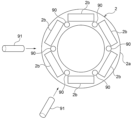
도 20은 밸런스 조정 방법의 다른 실시 형태를 도시하는 도면이다. 도 20에 도시한 바와 같이, 회전자(2)는, 환상의 철심(2a)과, 철심(2a)에 매립된 복수의 자석(2b)을 구비하고 있다. 복수의 자석(2b)은, 회전자(2)(보다 구체적으로는, 철심(2a))의 주위 방향을 따라서, 등간격으로 배치되어 있다. 작업자는, 회전자(2)의 주위 방향을 따라서, 복수의 추 삽입 구멍(90)을 형성하는 공정을 실행한다. 이 추 삽입 구멍(90)을 형성하는 공정은, 철심(2a)의 제조 시에 행해진다.Fig. 20 is a diagram showing another embodiment of a balance adjustment method. As shown in FIG. 20, the
추 삽입 구멍(90)은, 서로 인접하는 자석(2b) 사이에 형성되어 있다. 작업자는, 임펠러(1)의 무게 중심 위치를 결정하는 공정을 실행하여, 현재의 임펠러(1)의 무게 중심 위치를 결정한다. 임펠러(1)의 무게 중심 위치가 어긋나 있는 경우, 작업자는, 복수의 추 삽입 구멍(90)의 적어도 1개에 추(91)를 삽입하여, 무게 중심 위치를 조정하는 공정을 실행한다.The
일 실시 형태에서는, 임펠러(1)의 무게 중심 위치가 어긋나 있는 경우, 작업자는, 추 삽입 구멍(90)에 추(91)를 삽입하는 대신에, 임펠러(1)의 무게 중심 위치의 어긋남의 원인이 되는, 무게의 과잉분을 제거해도 된다.In one embodiment, when the position of the center of gravity of the
도 21a는 펌프 유닛의 다른 실시 형태를 도시하는 사시도이다. 도 21b는 도 21a에 도시한 펌프 유닛의 평면도이다. 도 21a 및 도 21b에 도시한 바와 같이, 펌프 유닛 PU는, 복수(본 실시 형태에서는, 3대)의 모터 펌프 MP와, 복수의 모터 펌프 MP를 가변속 운전하는 제어 장치(100)와, 제어 장치(100)에 전기적으로 접속되고, 또한 복수의 모터 펌프 MP에 공급되는 전류를 검출하는 전류 센서(101)를 구비하고 있다.Figure 21A is a perspective view showing another embodiment of a pump unit. FIG. 21B is a plan view of the pump unit shown in FIG. 21A. As shown in FIGS. 21A and 21B, the pump unit PU includes a plurality of motor pumps MP (three in this embodiment), a
본 실시 형태에서는, 2개의 전류 센서(101)가 배치되어 있지만, 적어도 1개의 전류 센서(101)가 배치되어도 된다. 전류 센서(101)의 일례로서, 홀 소자, CT(전류 변환기)를 들 수 있다.In this embodiment, two
펌프 유닛 PU는, 복수의 모터 펌프 MP로부터 연장되는 전력선(105) 및 신호선(106)과, 전류 센서(101), 전력선(105), 및 신호선(106)을 보호하는 보호 커버(107)를 구비하고 있다. 전력선(105) 및 신호선(106)은, 인버터(60)에 전기적으로 접속되어 있다.The pump unit PU is provided with a
복수의 모터 펌프 MP 사이에는, U상, V상, 및 W상의 구리 바(바꿔 말하면, 통전판, 동판)(108)가 걸쳐져 있고, 전류 센서(101)는, 이들 구리 바(108)의 1개에 접속되어 있다. 각 모터 펌프 MP는, 단자대(102)를 구비하고 있고, 구리 바(108)는, 단자대(102)에 접속되어 있다.Between the plurality of motor pumps MP, U-phase, V-phase, and W-phase copper bars (in other words, conductive plates, copper plates) 108 are stretched, and the
제어 장치(100)는, 인버터(60)에 전기적으로 접속되어 있고, 인버터(60)를 통해, 모터 펌프 MP의 동작을 제어하도록 구성되어 있다. 제어 장치(100)는, 인버터(60)의 외부에 배치되어도 되고, 또는 인버터(60)의 내부에 배치되어도 된다.The
제어 장치(100)는, 신호선(106)을 통해 전류 센서(101)로부터 신호를 수신하는 신호 수신부(100a)와, 모터 펌프 MP의 운전에 관한 정보나 운전 프로그램을 기억하는 기억부(100b)와, 신호 수신부에서 수신한 데이터 및 기억부에 기억된 데이터에 기초하여, 모터 펌프 MP의 운전을 제어하는 제어부(100c)를 구비하고 있다.The
본 실시 형태에서는, 펌프 유닛 PU는, 복수의 모터 펌프 MP에 대하여 1대의 인버터(60)를 구비하고 있지만, 펌프 유닛 PU는, 모터 펌프 MP의 수에 대응하는 수를 갖는 인버터(60)를 구비해도 된다. 복수의 모터 펌프 MP가 배치되어 있는 경우, 복수의 인버터(60)의 각각은, 제어 장치(100)에 의해 복수의 모터 펌프 MP의 각각의 동작을 제어한다.In this embodiment, the pump unit PU is provided with one
상술한 바와 같이, 모터 펌프 MP는, 데드 스페이스를 유효하게 활용한 콤팩트한 구조를 갖고 있다. 따라서, 이들 복수의 모터 펌프 MP를 직렬로 접속함으로써, 펌프 유닛 PU는, 그 설치 면적을 크게 하지 않고, 고양정으로 운전을 할 수 있다.As described above, the motor pump MP has a compact structure that effectively utilizes dead space. Therefore, by connecting these plural motor pumps MP in series, the pump unit PU can operate at a high lift without increasing its installation area.
모터 펌프 MP는 영구 자석형 모터를 구비한 회전 기계이다. 이와 같은 모터는, 기동 시에 강제적으로 전압을 인가함으로써, 무제어로 회전한다. 인버터(60)에 의한 모터 펌프 MP의 회전 속도의 제어는, 바로 개시되고, 그 후, 모터 펌프 MP의 정상 운전이 개시된다.The motor pump MP is a rotating machine with a permanent magnet motor. Such a motor rotates uncontrollably by forcibly applying voltage at startup. Control of the rotational speed of the motor pump MP by the
본 실시 형태에서는, 펌프 유닛 PU는, 복수의 모터 펌프 MP를 구비하고 있다. 따라서, 모터 펌프 MP의 회전 속도의 제어를 개시하기 전에, 복수의 모터 펌프 MP 사이에 있어서의 회전 속도차가 해소되면 문제없지만, 회전 속도차가 해소되지 않는 경우에는, 모터 펌프 MP의 기동 불량이 발생하였을 우려가 있다.In this embodiment, the pump unit PU is equipped with a plurality of motor pumps MP. Therefore, before starting control of the rotational speed of the motor pump MP, there is no problem if the rotational speed difference between the plurality of motor pumps MP is resolved. However, if the rotational speed difference is not resolved, startup failure of the motor pump MP may occur. There are concerns.
일반적으로, 회전자(2)의 자극수가 많아지면, 모터 펌프 MP는 매끄럽게 회전하여, 복수의 모터 펌프 MP 사이에 있어서의 회전 속도차가 해소되기 쉬워진다. 본 실시 형태에 있어서의 모터 펌프 MP는, 회전자(2)의 내측에 유로를 형성하는 구조를 갖고 있어, 회전자(2)의 외경을 크게 설계하고 있다.In general, as the number of magnetic poles of the
회전자(2)의 외경이 큰 경우, 회전자(2)의 외주 방향의 크기가 커지기 때문에, 복수의 자석을 용이하게 배치할 수 있어, 자극수를 증가시킬 수 있다. 이와 같은 구성에 의해, 펌프 유닛 PU는, 복수의 모터 펌프 MP 사이에 있어서의 회전 속도차를 해소할 수 있다. 또한, 본 실시 형태에서는, 저렴한 평면 자석을 사용함으로써, 회전자(2)는, 만곡한 자석을 사용하는 일반적인 모터와 비교하여, 비용을 삭감할 수 있다.When the outer diameter of the
또한, 본 실시 형태에서는, 모터 펌프 MP는, 고정자(3)가 고정자 케이싱(20)에 수용된 캔드 모터 구조를 갖고 있고, 회전자(2)와 고정자(3) 사이의 거리는, 일반적인 모터와 비교하여, 크다. 따라서, 모터 펌프 MP는, 토크의 변동 폭을 의미하는 토크 리플을 경감할 수 있고, 결과적으로, 펌프 유닛 PU는, 복수의 모터 펌프 MP 사이에 있어서의 회전 속도차를 해소할 수 있다.In addition, in this embodiment, the motor pump MP has a canned motor structure in which the
이와 같이, 펌프 유닛 PU는, 회전 속도차를 해소할 수 있지만, 모터 펌프 MP의 기동 시 및/또는 정상 운전 시에 있어서, 모터 펌프 MP를 더욱 안정적으로 운전하는 것이 바람직하다.In this way, the pump unit PU can eliminate the rotational speed difference, but it is desirable to operate the motor pump MP more stably during startup and/or normal operation of the motor pump MP.
따라서, 이하, 모터 펌프 MP의 제어 방법에 대하여 설명한다. 본 실시 형태에서는, 복수의 모터 펌프 MP는, 직렬로 접속되어 있다. 이 경우, 취급액에 이물이 포함되어 있으면, 이물이 모터 펌프 MP(특히, 1대째의 모터 펌프 MP)에 얽혀, 결과적으로, 이물에 의해 펌프 유닛 PU의 운전이 저해될 우려가 있다. 또한, 어떠한 원인에 의해, 복수의 모터 펌프 MP 사이에 있어서의 회전 속도차가 해소되지 않을 우려도 있다.Therefore, the control method of the motor pump MP will be described below. In this embodiment, a plurality of motor pumps MP are connected in series. In this case, if the handling liquid contains foreign matter, there is a risk that the foreign matter may become entangled in the motor pump MP (in particular, the first motor pump MP), and as a result, the operation of the pump unit PU may be impaired by the foreign matter. Additionally, there is a risk that the rotational speed difference between the plurality of motor pumps MP may not be resolved for some reason.
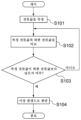
도 22는 제어 장치에 의한 모터 펌프의 제어 플로를 도시하는 도면이다. 도 22의 스텝 S101에 나타내는 바와 같이, 인버터(60)에 전기적으로 접속된 제어 장치(100)는, 인버터(60)의 출력 전류에 기초하여, 모터 펌프 MP의 현재의 운전 시에 있어서의 복수의 모터 펌프 MP의 전류값(보다 구체적으로는, 각 모터 펌프 MP의 전류값의 합계)을 측정한다.Fig. 22 is a diagram showing the control flow of the motor pump by the control device. As shown in step S101 of FIG. 22, the
그 후, 제어 장치(100)는, 모터 펌프 MP의 통상의 운전 시(보다 구체적으로는, 기동 시 및 정상 운전 시)에 있어서, 상정되는 상정 전류값에 기초하여, 하한 전류값을 산출하고, 측정된 전류값의 합계(측정 전류값 Amax)와 소정의 하한 전류값을 비교한다(스텝 S102 참조). 일 실시 형태에서는, 제어 장치(100)의 기억부(100b)는, 각 모터 펌프 MP의 상정 전류값과, 복수의 모터 펌프 MP의 상정 전류값을 기억하고 있다. 기억부(100b)는, 각 모터 펌프 MP의 상정 전류값으로부터 복수의 모터 펌프 MP의 상정 전류값을 산출해도 된다.Thereafter, the
제어 장치(100)는, 각 모터 펌프 MP의 정격 전류값 및 허용 전류값 중 적어도 1개에 기초하여, 「통상의 운전 시에 상정되는 상정 전류값」을 결정해도 되고, 모터 펌프 MP의 복수대 운전 시의 전류값에 기초하여 「통상의 운전 시에 상정되는 상정 전류값」을 결정해도 된다.The
일 실시 형태에서는, 제어 장치(100)는, 복수의 모터 펌프 MP의 대수에 기초하여, 하한 전류값을 결정한다. 예를 들어, 하한 전류값은, 다음 계산식에 의해 구해진다.In one embodiment, the
하한 전류값=복수의 모터 펌프 MP의 상정 전류값×(1-1/모터 펌프의 대수 n)Lower limit current value = assumed current value of multiple motor pumps MP × (1-1/number of motor pumps n)
본 실시 형태에서는, 3대의 모터 펌프 MP가 배치되어 있기 때문에, 하한 전류값은, 상정 전류값의 2/3이다.In this embodiment, since three motor pumps MP are arranged, the lower limit current value is 2/3 of the assumed current value.
스텝 S102 후, 제어 장치(100)는, 산출된 하한 전류값과 측정 전류값을 비교한다(스텝 S103 참조). 보다 구체적으로는, 제어 장치(100)는, 측정 전류값이 하한 전류값보다도 낮은지 여부를 판단한다(측정 전류값 Amax>하한 전류값).After step S102, the
측정 전류값이 하한 전류값보다도 낮은 경우에는(스텝 S103의 「"예"」 참조), 본 실시 형태에서는, 측정 전류값이 상정 전류값의 2/3(즉, 하한 전류값)를 하회하고 있는 경우에는, 제어 장치(100)는, 복수의 모터 펌프 MP 중 적어도 1개에 이상이 발생하고 있다고 판단한다(스텝 S104 참조). 측정 전류값이 하한 전류값보다도 저하되어 있지 않은 경우에는(스텝 S103의 「"아니오"」 참조), 제어 장치(100)는, 스텝 S102, S103을 반복한다.If the measured current value is lower than the lower limit current value (see "Yes" in step S103), in this embodiment, the measured current value is less than 2/3 of the assumed current value (i.e., lower limit current value). In this case, the
제어 장치(100)가 이상 발생을 판단한 경우에는, 제어 장치(100)는, 모터 펌프 MP의 운전을 계속하면서, 알람을 발보해도 되고, 모터 펌프 MP의 운전을 정지하고, 알람을 발보해도 된다.When the
이와 같은 제어 플로는, 모터 펌프 MP의 기동 시에 행해도 되고, 모터 펌프 MP의 정상 운전 시에 행해도 된다. 모터 펌프 MP의 기동 시에 제어 플로를 행하는 경우에는, 측정 전류값은, 복수의 모터 펌프 MP의 기동 시에 있어서의 기동 전류값에 상당하고, 상정 전류값은, 복수의 모터 펌프 MP의 통상의 기동 시에 상정되는 전류값이다.Such a control flow may be performed when the motor pump MP is started, or may be performed during normal operation of the motor pump MP. When performing a control flow when the motor pump MP is started, the measured current value corresponds to the starting current value when the plurality of motor pumps MP are started, and the assumed current value is the normal current value of the plurality of motor pump MPs. This is the current value assumed at startup.
모터 펌프 MP의 정상 운전 시에 제어 플로를 행하는 경우에는, 측정 전류값은, 복수의 모터 펌프 MP의 정상 운전 시에 있어서의 운전 전류값에 상당하고, 상정 전류값은, 복수의 모터 펌프 MP의 통상의 정상 운전 시에 상정되는 전류값이다.When performing a control flow during normal operation of the motor pump MP, the measured current value corresponds to the operating current value during normal operation of the plurality of motor pumps MP, and the assumed current value is the operating current value of the plurality of motor pumps MP. This is the current value assumed during normal normal operation.
기동 전류값 및 운전 전류값은, 동일해도 되고, 다르게 되어 있어도 된다. 마찬가지로, 통상의 기동 시에 상정되는 상정 전류값 및 통상의 정상 운전 시에 상정되는 상정 전류값은, 동일해도 되고, 다르게 되어 있어도 된다.The starting current value and the operating current value may be the same or different. Likewise, the assumed current value assumed during normal startup and the assumed current value assumed during normal normal operation may be the same or different.
일 실시 형태에서는, 제어 장치(100)는, 복수의 모터 펌프 MP의 토출측의 유량에 기초하여 상정 전류값을 결정해도 된다. 이 경우, 펌프 유닛 PU는, 취급액의 유량을 검출하는 유량 센서(도시 생략)를 구비하고 있고, 유량 센서는, 제어 장치(100)에 전기적으로 접속되어 있다.In one embodiment, the
제어 장치(100)의 기억부(100b)는, 통상의 운전 시에 있어서의 취급액의 유량과, 통상의 운전 시에 있어서 복수의 모터 펌프 MP에 공급되는 전류의 상관 관계를 나타내는 데이터를 기억하고 있다. 제어 장치(100)는, 이 데이터에 기초하여, 상정 전류값을 결정하고, 결정된 상정 전류값에 기초하여, 하한 전류값을 산출한다. 하한 전류값의 산출식의 일례로서, 상기 계산식을 들 수 있다.The
제어 장치(100)는, 복수의 모터 펌프 MP의 정상 운전 시에 있어서의 측정 전류값과, 하한 전류값을 비교하고, 측정 전류값이 하한 전류값보다도 낮은 경우에는, 복수의 모터 펌프 MP 중 적어도 1개에 이상이 발생하고 있다고 판단한다.The
일 실시 형태에서는, 제어 장치(100)는, 복수의 모터 펌프 MP의 토출측의 압력에 기초하여, 상정 전류값을 결정해도 된다. 이 경우, 펌프 유닛 PU는, 취급액의 압력을 검출하는 압력 센서(도시 생략)를 구비하고 있고, 압력 센서는, 제어 장치(100)에 전기적으로 접속되어 있다.In one embodiment, the
제어 장치(100)의 기억부(100b)는, 취급액의 압력과, 통상의 운전 시에 있어서 복수의 모터 펌프 MP에 공급되는 전류의 상관 관계를 나타내는 데이터를 기억하고 있다. 제어 장치(100)는, 이 데이터에 기초하여, 상정 전류값을 결정하고, 결정된 상정 전류값에 기초하여, 하한 전류값을 산출한다. 하한 전류값의 산출식의 일례로서, 상기 계산식을 들 수 있다.The
제어 장치(100)는, 복수의 모터 펌프 MP의 정상 운전 시에 있어서의 측정 전류값과, 하한 전류값을 비교하고, 측정 전류값이 하한 전류값보다도 낮은 경우에는, 복수의 모터 펌프 MP 중 적어도 1개에 이상이 발생하고 있다고 판단한다.The
도 21a 및 도 21b에 도시한 실시 형태에서는, 펌프 유닛 PU는, 1대째의 모터 펌프 MP(제1 모터 펌프 MP)와 2대째의 모터 펌프 MP(제2 모터 펌프 MP) 사이에 배치된 전류 센서(101)(제1 전류 센서(101))와, 제2 모터 펌프 MP와 3대째의 모터 펌프 MP(제3 모터 펌프 MP) 사이에 배치된 전류 센서(101)(제2 전류 센서(101))를 구비하고 있다.In the embodiment shown in FIGS. 21A and 21B, the pump unit PU is a current sensor disposed between the first motor pump MP (first motor pump MP) and the second motor pump MP (second motor pump MP). (101) (first current sensor 101), and a current sensor 101 (second current sensor 101) disposed between the second motor pump MP and the third motor pump MP (third motor pump MP) ) is provided.
따라서, 제어 장치(100)는, 제1 전류 센서(101)로부터 보내지는 신호에 기초하여, 제1 모터 펌프 MP의 전류값(즉, 측정 전류값 Aa1)을 측정하고, 제2 전류 센서(101)로부터 보내지는 신호에 기초하여, 제1 모터 펌프 MP의 측정 전류값 Aa1 및 제2 모터 펌프 MP의 측정 전류값 Aa2의 합계(즉, 측정 전류값 Ab(=Aa1+Aa2))를 측정할 수 있다.Therefore, the
제어 장치(100)는, 측정 전류값 Aa1과, 각 모터 펌프 MP의 통상의 운전 시(시동 시, 정상 운전 시)에 상정되는 상정 전류값을 비교하고, 측정 전류값 Aa1이 상정 전류값보다도 낮은(Aa1<상정 전류값) 경우에는, 제1 모터 펌프 MP에 이상이 발생하고 있다고 판단한다.The
제어 장치(100)는, 측정 전류값 Aa1과, 각 모터 펌프 MP의 통상의 운전 시(시동 시, 정상 운전 시)에 상정되는 상정 전류값을 비교하고, 측정 전류값 Aa1이 상정 전류값보다도 크고(Aa1>상정 전류값), 또한 측정 전류값 Ab로부터 측정 전류값 Aa1을 감산한 값(즉, Ab-Aa1)이 상정 전류값보다도 작은((Ab-Aa1)<상정 전류값) 경우에는, 제2 모터 펌프 MP에 이상이 발생하고 있다고 판단한다. 측정 전류값 Ab로부터 측정 전류값 Aa1을 감산한 값은, 측정 전류값 Aa2에 상당한다.The
제어 장치(100)는, 측정 전류값 Amax가 하한 전류값보다도 낮다고 판단하고, 또한 제1 모터 펌프 MP 및 제2 모터 펌프 MP에 이상이 발생하고 있지 않다고 판단한 경우에는, 제3 모터 펌프 MP에 이상이 발생하고 있다고 결정한다.When the
펌프 유닛 PU가 직렬로 접속된 4대의 모터 펌프 MP를 구비하고 있는 경우, 펌프 유닛 PU는, 제3 모터 펌프 MP와 4대째의 모터 펌프 MP(제4 모터 펌프 MP) 사이에 배치된 전류 센서(101)(제3 전류 센서(101))를 구비하고 있다.When the pump unit PU is equipped with four motor pumps MP connected in series, the pump unit PU has a current sensor disposed between the third motor pump MP and the fourth motor pump MP (fourth motor pump MP). 101) (third current sensor 101).
제어 장치(100)는, 제3 전류 센서(101)로부터 보내지는 신호에 기초하여 제1 모터 펌프 MP의 측정 전류값 Aa1, 제2 모터 펌프 MP의 측정 전류값 Aa2, 및 제3 모터 펌프 MP의 측정 전류값 Aa3의 합계(즉, 측정 전류값 Ac)를 측정할 수 있다.Based on the signal sent from the third
제어 장치(100)는, 측정 전류값 Aa1이 상정 전류값보다도 크고(Aa1>상정 전류값), 측정 전류값 Ab로부터 측정 전류값 Aa1을 감산한 값(즉, Ab-Aa1)이 상정 전류값보다도 크고((Ab-Aa1)>상정 전류값), 또한, 측정 전류값 Ac로부터 측정 전류값 Ab를 감산한 값(즉, Ac-Ab, 여기서, Ab=Aa1+Aa2)이 상정 전류값보다도 낮은 경우에는, 제3 모터 펌프 MP에 이상이 발생하고 있다고 판단한다. 측정 전류값 Ac로부터 측정 전류값 Ab를 감산한 값은, 상정 전류값 Aa3에 상당한다.The
제어 장치(100)는, 측정 전류값 Amax가 하한 전류값보다도 낮다고 판단하고, 또한 제1 모터 펌프 MP, 제2 모터 펌프 MP, 및 제3 모터 펌프 MP에 이상이 발생하고 있지 않다고 판단한 경우에는, 제4 모터 펌프 MP에 이상이 발생하고 있다고 결정한다. 또한, 펌프 유닛 PU가 직렬로 접속된 5대 이상의 모터 펌프 MP를 구비하고 있는 경우에 있어서도, 제어 장치(100)는, 상술한 방법과 마찬가지의 방법에 의해, 각 모터 펌프 MP의 이상을 판단할 수 있다.When the
상술한 실시 형태에서는, 직렬로 접속된 복수의 모터 펌프 MP의 제어 방법에 대하여, 설명하였지만, 펌프 유닛 PU는, 병렬로 접속된 복수의 모터 펌프 MP를 제어해도 된다. 병렬로 접속된 복수의 모터 펌프 MP(도 11 및 도 12 참조)를 제어하는 경우, 제어 장치(100)는, 복수의 모터 펌프 MP의 각각의 기동 타이밍을 어긋나게 하도록 구성되어도 된다.In the above-described embodiment, the control method of the plurality of motor pumps MP connected in series has been described, but the pump unit PU may control the plurality of motor pumps MP connected in parallel. When controlling a plurality of motor pumps MP (see FIGS. 11 and 12) connected in parallel, the
기동 타이밍을 어긋나게 함으로써, 펌프 유닛 PU는, 배관(65) 내에 선회류를 형성할 수 있다. 선회류를 형성함으로써, 배관(65)에 부착되는 이물이나 공기를 제거할 수 있고, 나아가, 취급액의 체류를 방지할 수 있다.By shifting the startup timing, the pump unit PU can form a swirling flow within the
선회류를 형성하기 위해, 제어 장치(100)는, 복수의 모터 펌프 MP 중 1대(제1 모터 펌프 MP)를 기동한 후, 기동된 모터 펌프 MP(즉, 제1 모터 펌프 MP)에 인접하는 모터 펌프 MP(제2 모터 펌프 MP)를 기동해도 된다. 이와 같이, 인접하는 모터 펌프 MP를 연속적으로 기동함으로써, 펌프 유닛 PU는, 모터 펌프 MP의 기동순을 따라서 선회하는 선회류를 형성할 수 있다.In order to form a swirling flow, the
예를 들어, 3대의 모터 펌프 MP가 배치되어 있는 경우, 제어 장치(100)는, 제1 모터 펌프 MP를 기동하고, 그 후, 제2 모터 펌프 MP를 기동해도 되고, 또는, 제3 모터 펌프 MP를 기동한 후, 제3 모터 펌프 MP에 인접하는 제1 모터 펌프 MP를 기동해도 된다.For example, when three motor pumps MP are arranged, the
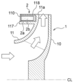
도 23은 임펠러의 다른 실시 형태를 도시하는 도면이다. 본 실시 형태에서는, 베어링(5)의 도시는 생략되어 있다. 상술한 실시 형태에서는, 임펠러(1)는, 측판(11)의 외연부(11a)로부터 흡입부(15)를 향하여 연장되는 환상의 돌기부(17)를 구비하고 있다(도 1 참조). 도 23에 도시한 실시 형태에서는, 임펠러(1)의 측판(11)은, 측판(11)의 외연부(11a)의 반경 방향 내측에 배치된 환상의 돌기부(117)를 갖고 있다.23 is a diagram showing another embodiment of an impeller. In this embodiment, illustration of the
회전자(2)는, 측판(11)의 외연부(11a)와 돌기부(117) 사이에 형성된 환상 단차부에 배치되어 있고, 회전자(2)의 노출 부분은 커버(110)에 의해 덮여 있다. 커버(110)는 모터 펌프 MP의 구성 요소의 하나이다. 커버(110)의 일례로서, 내부식성을 갖는 캔, 수지 코트, 또는 Ni 도금 코트를 들 수 있다.The
일 실시 형태에서는, 회전자(2)의 철심(2a)은, 접착제, 압입, 수축 끼워맞춤, 용접 등의 수단에 의해, 돌기부(117)에 접합되어 있다. 마찬가지로, 커버(110)는, 접착제, 압입, 수축 끼워맞춤, 용접 등의 수단에 의해, 임펠러(1)에 접합되어 있다.In one embodiment, the
도 24는 임펠러의 다른 실시 형태를 도시하는 도면이다. 본 실시 형태에서는, 베어링(5)의 도시는 생략되어 있다. 도 24에 도시한 바와 같이, 임펠러(1)는, 돌기부(117)의 반경 방향 외측에 배치된 환상의 장착부(118)를 구비해도 된다. 장착부(118)와 돌기부(117) 사이의 환상의 공간에 회전자(2)를 삽입함으로써, 회전자(2)를 보다 확실하게 측판(11)에 고정할 수 있다. 본 실시 형태에 있어서도, 회전자(2)의 노출 부분은, 커버(110)로 덮여 있다.Figure 24 is a diagram showing another embodiment of the impeller. In this embodiment, illustration of the
도 25는 커버와 측판 사이에 배치된 시일 부재를 도시하는 도면이다. 본 실시 형태에서는, 베어링(5)의 도시는 생략되어 있다. 도 25에 도시한 바와 같이, 커버(110)와 측판(11)(보다 구체적으로는, 측판(11)의 외연부(11a) 및 돌기부(117)) 사이에 시일 부재(예를 들어, O링)(120, 121)를 배치함으로써, 액체의, 회전자(2)로의 접촉을 확실하게 방지할 수 있다.Fig. 25 is a view showing a seal member disposed between the cover and the side plate. In this embodiment, illustration of the
도 1 내지 도 25에 도시한 실시 형태에 관한 임펠러(1)는, 예를 들어 주조 제조나 스테인리스 프레스 성형이나 수지 성형 등의 수단에 의해, 제조된다. 이하에 설명하는 도 26 내지 도 34에 도시한 실시 형태에 관한 임펠러(1)도 마찬가지로, 주조 제조나 스테인리스 프레스 성형이나 수지 성형 등의 수단에 의해, 제조되어도 된다.The
도 26은 임펠러의 다른 실시 형태를 도시하는 도면이다. 본 실시 형태에서는, 베어링(5)의 도시는 생략되어 있다. 도 26에 도시한 바와 같이, 회전자(2)는, 주판(10)과 측판(11) 사이에 형성된 임펠러(1)의 유로(즉, 출구 유로)를 차단하도록, 측판(11)의 외연부(11a)에 고정되어 있다. 본 실시 형태에 있어서도, 회전자(2)는, 흡입측 영역 Ra에 배치되어 있다.Figure 26 is a diagram showing another embodiment of the impeller. In this embodiment, illustration of the
도 26에 도시한 실시 형태에서는, 회전자(2)는, 커버(110)로 덮여 있지 않고, 회전자(2)는, 내부식성을 갖는 재질로 구성되어 있다. 상술한 실시 형태에 있어서도, 회전자(2)는, 반드시 커버(110)로 덮일 필요는 없고, 내부식성을 갖는 재질로 구성되어도 된다. 일 실시 형태에서는, 회전자(2)는, 커버(110)로 덮여도 된다.In the embodiment shown in FIG. 26, the
이와 같은 구성에 의해, 출구 유로를 통과하는 취급액은, 회전자(2)의 내주면에 충돌하여, 취급액의 방향이 전환된다. 그 후, 취급액은, 주판(10)과 토출 케이싱(22) 사이의 간극을 통해, 토출구(22a)로부터 토출된다.With this configuration, the liquid passing through the outlet flow path collides with the inner peripheral surface of the
도 23 내지 도 26에 도시한 실시 형태에 있어서도, 회전자(2) 및 베어링(5)은, 임펠러(1)의 흡입측 영역 Ra에 배치되어 있기 때문에, 모터 펌프 MP는, 콤팩트한 구조를 갖고 있다.23 to 26, since the
도 27은 모터 펌프의 다른 실시 형태를 도시하는 도면이다. 도 27에 도시한 바와 같이, 모터 펌프 MP는, 흡입구(21a) 측에 배치된 제1 임펠러(1A)와, 토출구(22a) 측에 배치된 제2 임펠러(1B)와, 제1 임펠러(1A) 및 제2 임펠러(1B)에 접속된 연통축(126)을 구비하고 있다. 회전자(2)는, 제1 임펠러(1A)에 고정되어 있고, 고정자(3)는 회전자(2)의 반경 방향 외측에 배치되어 있다. 베어링(5)은 제1 임펠러(1A)를 지지하고 있고, 제2 임펠러(1B)는, 연통축(126)을 통해 베어링(5)에 의해 지지되고 있다.Fig. 27 is a diagram showing another embodiment of a motor pump. As shown in FIG. 27, the motor pump MP includes a
도 27에 도시한 실시 형태에서는, 모터 펌프 MP는, 제1 임펠러(1A)와 제2 임펠러(1B) 사이에 배치된 중간 케이싱(125)을 구비하고 있다. 중간 케이싱(125)은, 제1 임펠러(1A)의 토출측과 제2 임펠러(1B)의 흡입측을 격리하는 환상의 격벽이다. 본 실시 형태에서는, 중간 케이싱(125)은, 고정자 케이싱(20)에 고정되어 있다.In the embodiment shown in FIG. 27, the motor pump MP is provided with an
도 27에 도시한 실시 형태에서는, 모터 펌프 MP는, 2매의 임펠러(1)를 구비하고 있지만, 임펠러(1)의 수는 본 실시 형태에 한정되지는 않는다. 모터 펌프 MP는, 임펠러(1)의 수에 따라서, 복수의 중간 케이싱(125)을 구비해도 된다. 바꿔 말하면, 모터 펌프 MP는, 제1 임펠러(1A) 및 제2 임펠러(1B)를 적어도 포함하는, 복수의 임펠러(1)를 구비해도 된다.In the embodiment shown in FIG. 27, the motor pump MP is provided with two
도 28은 모터 펌프의 다른 실시 형태를 도시하는 도면이다. 도 28에 도시한 바와 같이, 모터 펌프 MP는, 연통축(126)을 회전 가능하게 지지하고, 또한 제2 임펠러(1B)의 토출측에 배치된 토출측 베어링(128)을 더 구비하고 있다. 토출측 베어링(128)은, 토출 케이싱(22)에 장착되어 있고, 토출측 베어링(128)과 토출 케이싱(22) 사이의 간극에는, 시일 부재(예를 들어, O링)(127A, 127B)가 배치되어 있다. 또한, 도 28에 도시한 실시 형태에 있어서도, 모터 펌프 MP는, 2매의 임펠러(1)를 구비하고 있지만, 임펠러(1)의 수는 본 실시 형태에 한정되지는 않는다. 모터 펌프 MP는, 제1 임펠러(1A) 및 제2 임펠러(1B)를 적어도 포함하는, 복수의 임펠러(1)를 구비해도 된다.Fig. 28 is a diagram showing another embodiment of a motor pump. As shown in FIG. 28, the motor pump MP rotatably supports the
도 28에 도시한 바와 같이, 토출 케이싱(22)은, 토출구(22a)에 연통하는 유로(129)를 갖고 있다. 유로(129)는, 연통축(126)의 반경 방향 외측에 배치되어 있다. 제2 임펠러(1B)로부터 토출된 취급액은 유로(129) 및 토출구(22a)를 통해 외부로 토출된다.As shown in FIG. 28, the
도 28에 도시한 실시 형태에서는, 제1 임펠러(1A) 및 제2 임펠러(1B)는, 베어링(5)뿐만 아니라, 토출측 베어링(128)에 의해서도 지지되고 있다. 토출측 베어링(128)은, 레이디얼 베어링이다. 이와 같은 구조에 의해, 모터 펌프 MP는, 제1 임펠러(1A) 및 제2 임펠러(1B)의, 레이디얼 방향으로의 변위를 억제할 수 있다.In the embodiment shown in FIG. 28, the
도 29는 모터 펌프의 다른 실시 형태를 도시하는 도면이다. 도 29에 도시한 바와 같이, 모터 펌프 MP는, 1매의 임펠러(1)가 고정된 연통축(126)과, 연통축(126)을 회전 가능하게 지지하는 토출측 베어링(128)을 구비해도 된다.Fig. 29 is a diagram showing another embodiment of a motor pump. As shown in FIG. 29, the motor pump MP may be provided with a
도 30은 운전 조건에 따라서, 다양한 구성 부품을 선택 가능한 모터 펌프를 도시하는 도면이다. 도 30에 있어서, 횡축은 유량을 나타내고 있고, 종축은 양정을 나타내고 있다. 도 30에 도시한 바와 같이, 모터 펌프 MP는, 다양한 운전 조건(즉, 유량의 크기 및 양정의 크기)에 따라서, 최적의 구성 부품을 선택 가능하게 구성되어 있다.Figure 30 is a diagram showing a motor pump in which various components can be selected depending on operating conditions. In Figure 30, the horizontal axis represents the flow rate, and the vertical axis represents the head. As shown in FIG. 30, the motor pump MP is configured to enable selection of optimal components according to various operating conditions (i.e., size of flow rate and size of head).
도 30에 도시한 실시 형태에서는, 모터 펌프 MP는, 양정의 크기 및 유량의 크기에 따라서, 복수(본 실시 형태에서는, 4개)의 다른 구성으로부터 선택 가능하다(도 30의 MPA 내지 MPD 참조). 본 실시 형태에 있어서, 모터 펌프 MP는, 다른 사이즈를 갖는 복수의 임펠러(1)와, 복수의 임펠러(1)에 고정되며, 또한 다른 길이를 갖는 복수의 회전자(2)와, 복수의 회전자(2)의 길이에 대응하는 길이를 갖는 복수의 고정자(3)와, 복수의 고정자(3)를 수용하고, 또한 복수의 고정자(3)의 길이에 대응하는 길이를 갖는 복수의 고정자 케이싱(20)을 구비하고 있다.In the embodiment shown in FIG. 30, the motor pump MP can be selected from a plurality of (four in this embodiment) different configurations depending on the size of the head and the size of the flow rate (see MPA to MPD in FIG. 30). . In this embodiment, the motor pump MP includes a plurality of
모터 펌프 MP의 모터 용량의 크기는, 고정자(3)의 길이 Lg의 길이에 의존하고 있다. 모터 펌프 MP의 양정의 크기는, 임펠러(1)의 직경 D1의 크기에 의존하고 있다. 모터 펌프 MP의 유량의 크기는, 임펠러(1)의 출구 유로 B2의 크기에 의존하고 있다.The size of the motor capacity of the motor pump MP depends on the length Lg of the
복수의 임펠러(1)는, 동일한 직경을 갖는 복수의 측판(11)과 다른 직경을 갖는 복수의 주판(10)을 구비하고 있다. 본 명세서에 있어서, 임펠러(1)의 직경 D1은, 주판(10)의 직경에 상당한다.The plurality of
모터 펌프 MPA 및 모터 펌프 MPB의 관계성에 대하여 설명한다. 도 30에 도시한 바와 같이, 모터 펌프 MPA 및 모터 펌프 MPB는, 동일한 모터 용량을 갖고 있다(즉, LgA=LgB). 모터 펌프 MPA는, 모터 펌프 MPB보다도 높은 양정 능력을 갖고 있다(즉, D1A>D1B). 모터 펌프 MPB는, 모터 펌프 MPA보다도 높은 유량 능력을 갖고 있다(즉, B2B>B2A).The relationship between motor pump MPA and motor pump MPB will be explained. As shown in Fig. 30, motor pump MPA and motor pump MPB have the same motor capacity (i.e., LgA = LgB). Motor pump MPA has a higher head capacity than motor pump MPB (i.e. D1A>D1B). Motor pump MPB has a higher flow capacity than motor pump MPA (i.e. B2B>B2A).
모터 펌프 MPA 및 모터 펌프 MPC의 관계성에 대하여 설명한다. 모터 펌프 MPC는, 모터 펌프 MPA보다도 큰 모터 용량을 갖고 있다(즉, LgC>LgA). 모터 펌프 MPC는, 모터 펌프 MPA와 동일한 양정 능력을 갖고 있다(즉, D1A=D1C). 모터 펌프 MPC는, 모터 펌프 MPA보다도 높은 유량 능력을 갖고 있다(즉, B2C>B2A).The relationship between motor pump MPA and motor pump MPC will be explained. Motor pump MPC has a larger motor capacity than motor pump MPA (i.e., LgC>LgA). The motor pump MPC has the same head capacity as the motor pump MPA (i.e. D1A=D1C). Motor pump MPC has a higher flow capacity than motor pump MPA (i.e. B2C>B2A).
모터 펌프 MPB 및 모터 펌프 MPC의 관계성에 대하여 설명한다. 모터 펌프 MPC는, 모터 펌프 MPB보다도 큰 모터 용량을 갖고 있다(즉, LgC>LgB). 모터 펌프 MPC는, 모터 펌프 MPB보다도 높은 양정 능력을 갖고 있다(즉, D1C>D1B). 모터 펌프 MPB의 임펠러(1)의 출구 유로 B2B는, 모터 펌프 MPC의 임펠러(1)의 출구 유로 B2C와 동일하거나, 또는 출구 유로 B2C보다도 큰 크기를 갖고 있다(즉, B2B≥B2C).The relationship between motor pump MPB and motor pump MPC will be explained. Motor pump MPC has a larger motor capacity than motor pump MPB (i.e., LgC>LgB). The motor pump MPC has a higher head capacity than the motor pump MPB (i.e. D1C>D1B). The outlet flow path B2B of the
모터 펌프 MPC 및 모터 펌프 MPD의 관계성에 대하여 설명한다. 모터 펌프 MPC는, 모터 펌프 MPD와 동일한 모터 용량을 갖고 있다(즉, LgC=LgD). 모터 펌프 MPC는, 모터 펌프 MPD보다도 높은 양정 능력을 갖고 있다(즉, D1C>D1D). 모터 펌프 MPD는, 모터 펌프 MPC보다도 높은 유량 능력을 갖고 있다(즉, B2D>B2C).The relationship between motor pump MPC and motor pump MPD will be explained. The motor pump MPC has the same motor capacity as the motor pump MPD (i.e. LgC=LgD). Motor pump MPC has a higher head capacity than motor pump MPD (i.e. D1C>D1D). Motor pump MPD has a higher flow capacity than motor pump MPC (i.e. B2D>B2C).
모터 펌프 MPB 및 모터 펌프 MPD의 관계성에 대하여 설명한다. 모터 펌프 MPD는, 모터 펌프 MPB보다도 큰 모터 용량을 갖고 있다(즉, LgD>LgB). 모터 펌프 MPD는, 모터 펌프 MPB보다도 높은 유량 능력을 갖고 있다(즉, B2D>B2B). 모터 펌프 MPB는, 모터 펌프 MPD와 동일한 양정 능력을 갖고 있다(즉, D1B=D1D).The relationship between motor pump MPB and motor pump MPD will be explained. Motor pump MPD has a larger motor capacity than motor pump MPB (i.e., LgD>LgB). Motor pump MPD has a higher flow capacity than motor pump MPB (i.e. B2D>B2B). Motor pump MPB has the same head capacity as motor pump MPD (i.e. D1B=D1D).
도 30에 도시한 바와 같이, 모든 모터 펌프 MP에 있어서, 고정자 케이싱(20)의 내경 D2 및 외경 D3은, 동일하다. 따라서, 작업자는, 양정 능력 및 유량 능력에 따라서, 다른 사이즈를 갖는 구성 부품을 준비해 두고, 모터 펌프 MP의 운전 조건에 기초하여, 복수의 구성 부품으로부터 최적의 구성 부품을 선택할 수 있다.As shown in FIG. 30, in all motor pumps MP, the inner diameter D2 and outer diameter D3 of the
고정자 케이싱(20)의 내경 D2 및 외경 D3을 동일하게 함으로써, 양정 능력이나 유량 능력에 의존하지 않는 구성 부품(예를 들어, 베어링(5), 흡입 케이싱(21) 및 토출 케이싱(22))의 사이즈를 변경하지 않고, 펌프 유닛 PU는, 그 성능을 용이하게 변경할 수 있다.By making the inner diameter D2 and the outer diameter D3 of the
도 31a는 다른 실시 형태에 관한 모터 펌프의 단면도이며, 도 31b는 도 31a에 도시한 모터 펌프를 축선 방향으로부터 보았을 때의 도면이다. 도 31a 및 도 31b에 도시한 바와 같이, 모터 펌프 MP는, 임펠러(1)의 배면측에 배치된 선회 방지부(바꿔 말하면, 페일 스톱)(130)를 구비해도 된다.FIG. 31A is a cross-sectional view of a motor pump according to another embodiment, and FIG. 31B is a view of the motor pump shown in FIG. 31A when viewed from the axial direction. As shown in FIGS. 31A and 31B, the motor pump MP may be provided with a turning prevention portion (in other words, fail stop) 130 disposed on the rear side of the
도 31b에 도시한 실시 형태에서는, 1개의 선회 방지부(130)가 배치되어 있지만, 적어도 1개의 선회 방지부(130)가 배치되어도 된다. 선회 방지부(130)는, 토출 케이싱(22)에 고정되어 있고, 임펠러(1)의 주판(10)에 대향하고 있다. 선회 방지부(130)는, 임펠러(1)로부터 토출된 취급액의, 임펠러(1)와 토출 케이싱(22) 사이에서의 선회를 방지할 수 있다.In the embodiment shown in FIG. 31B, one
도 32a는 다른 실시 형태에 관한 모터 펌프의 단면도이며, 도 32b는 도 32a에 도시한 모터 펌프의 흡입 케이싱의 정면도이다. 도 32a 및 도 32b에 도시한 바와 같이, 모터 펌프 MP는, 평탄한 플랜지 형상을 갖는 흡입 케이싱(141) 및 토출 케이싱(142)을 구비하고 있다.FIG. 32A is a cross-sectional view of a motor pump according to another embodiment, and FIG. 32B is a front view of the suction casing of the motor pump shown in FIG. 32A. As shown in FIGS. 32A and 32B, the motor pump MP is provided with a
상술한 실시 형태에서는, 흡입 케이싱(21)의 흡입구(21a)는, 흡입 케이싱(21)의 외면으로부터 돌출되어 있고, 마찬가지로, 토출 케이싱(22)의 토출구(22a)는, 토출 케이싱(22)의 외면으로부터 돌출되어 있다. 본 실시 형태에서는, 흡입 케이싱(141)은 평탄한 플랜지 형상을 갖고 있기 때문에, 흡입구(141a)는, 흡입 케이싱(141)의 외면과 동일 평면 상에 형성되어 있다. 마찬가지로, 토출 케이싱(142)은 평탄한 플랜지 형상을 갖고 있기 때문에, 토출구(142a)는, 토출 케이싱(142)의 외면과 동일 평면 상에 형성되어 있다.In the above-described embodiment, the
이와 같은 구조에 의해, 모터 펌프 MP에 접속된 접속관(140)을 흡입 케이싱(141)에 직접 접속할 수 있다. 도시하지 않지만, 접속관(140)을 평탄한 플랜지 형상을 갖는 토출 케이싱(142)에 직접 접속해도 된다.With this structure, the
이와 같은 구성에 의해, 접속관(140) 및 흡입 케이싱(141)을 연결하는 부재(연결 부재)를 배치할 필요는 없어, 배관(도시 생략)을 모터 펌프 MP에 접속하기 위한 부품 개수를 삭감할 수 있다.With this configuration, there is no need to arrange a member (connection member) connecting the
연결 부재는 액체의 누설이 상정되는 부재이기 때문에, 연결 부재를 배제함으로써, 액체의 누설을 확실하게 방지할 수 있다. 본 실시 형태에서는, 도시하지 않지만, 접속관(140)과 흡입 케이싱(141) 사이에는, 시일 부재(예를 들어, O링 또는 가스킷)가 배치되어 있다.Since the connecting member is a member from which leakage of liquid is expected, leakage of liquid can be reliably prevented by excluding the connecting member. In this embodiment, although not shown, a sealing member (for example, an O-ring or a gasket) is disposed between the
흡입 케이싱(141)의 흡입구(141a)의 반경 방향 외측에는, 접속관(140)과 흡입 케이싱(141)을 체결하기 위한 체결구(150)가 삽입되는 삽입 구멍(141b)이 형성되어 있다. 접속관(140)은, 삽입 구멍(141b)에 연통하는 관통 구멍(140a)을 갖고 있다. 작업자는, 체결구(150)를 관통 구멍(140a) 및 삽입 구멍(141b)에 삽입함으로써, 접속관(140) 및 흡입 케이싱(141)을 서로 체결할 수 있다.On the radial outer side of the
토출 케이싱(142)의 토출구(142a)의 반경 방향 외측에는, 관통 볼트(25)의 헤드부(25a)를 수용하는 볼트 수용부(142b)가 형성되어 있다. 볼트 수용부(142b)에 관통 볼트(25)의 헤드부(25a)를 수용함으로써, 헤드부(25a)가 토출 케이싱(22)으로부터 돌출되는 것을 방지할 수 있다.On the radial outer side of the
일 실시 형태에서는, 흡입 케이싱(141)은, 볼트 수용부(142b)에 상당하는 볼트 수용부를 가져도 된다. 즉, 흡입 케이싱(141) 및 토출 케이싱(142) 중 적어도 1개는, 관통 볼트(25)의 헤드부(25a)를 수용하는 볼트 수용부를 갖고 있다.In one embodiment, the
도 33은 직렬로 접속된 모터 펌프를 구비하는 펌프 유닛을 도시하는 도면이다. 도 33에 도시한 바와 같이, 도 32a 및 도 32b에 도시한 모터 펌프 MP는, 평탄한 플랜지 형상을 갖는 흡입 케이싱(141) 및 토출 케이싱(142)을 구비하고 있기 때문에, 서로 인접하여 배치된 흡입 케이싱(141) 및 토출 케이싱(142)은, 서로 면접촉할 수 있다. 서로 면접촉하는 흡입 케이싱(141) 및 토출 케이싱(142)은, 중간 케이싱에 상당한다.Figure 33 is a diagram showing a pump unit including a motor pump connected in series. As shown in Figure 33, the motor pump MP shown in Figures 32a and 32b is provided with a
도시하지 않지만, 서로 면접촉하는 흡입 케이싱(141)과 토출 케이싱(142) 사이에는, 시일 부재(예를 들어, O링 또는 가스킷)가 배치되어 있다.Although not shown, a sealing member (for example, an O-ring or a gasket) is disposed between the
본 실시 형태에 따르면, 중간 케이싱(61)(도 10 참조)을 배치할 필요는 없고, 동일 구조를 갖는 복수의 모터 펌프 MP를 직접, 직렬로 접속하는 것만의 간단한 작업에 의해, 복수의 모터 펌프 MP를 구비하는 펌프 유닛 PU를 구성할 수 있다.According to this embodiment, there is no need to arrange the intermediate casing 61 (see FIG. 10), and a plurality of motor pumps MP having the same structure can be connected directly in series by a simple operation. A pump unit PU including an MP can be configured.
본 실시 형태에 관한 모터 펌프 MP는, 심플한 주요한 구성 부품(즉, 임펠러(1)와, 회전자(2) 및 고정자(3)와, 베어링(5))을 구비하고 있어, 소형 경량화가 도모되어 있다. 따라서, 관통 볼트(25)를 사용함으로써, 직렬로 배치된 복수의 모터 펌프 MP를, 용이하게 일체적으로 체결할 수 있다.The motor pump MP according to this embodiment has simple main components (namely, the
또한, 흡입 케이싱(141) 및 토출 케이싱(142)을 서로 면접촉함으로써, 펌프 유닛 PU의 열전도율을 향상시킬 수 있어, 복수의 모터 펌프 MP 사이에 있어서의 온도 평형을 도모할 수 있다. 결과적으로, 펌프 유닛 PU는, 안정적으로 운전할 수 있다.Additionally, by bringing the
도 34는 임펠러의 다른 실시 형태를 도시하는 도면이다. 상술한 실시 형태에서는, 임펠러(1)는, 원심 임펠러이다. 보다 구체적으로는, 임펠러(1)는, 중심선 CL 방향과 수직으로 연장되는 주판(10)을 구비하고 있고, 임펠러(1)에 의해 승압된 액체는, 중심선 CL에 대하여 수직으로 토출된다. 도 34에 도시한 실시 형태에서는, 임펠러(1)는, 사류 임펠러이다. 보다 구체적으로는, 임펠러(1)는, 중심선 CL 방향에 대하여 소정의 각도로 경사지는 주판(160)을 구비하고 있다. 주판(160)은, 흡입측으로부터 토출측을 향하여 경사져 있어, 임펠러(1)에 의해 승압된 액체는, 중심선 CL에 대하여 경사 방향 외측으로 토출된다.Figure 34 is a diagram showing another embodiment of the impeller. In the above-described embodiment, the
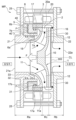
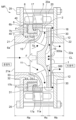
도 35는 모터 펌프의 다른 실시 형태를 도시하는 도면이다. 도 35에 도시한 바와 같이, 모터 펌프 MP는, 회전자(2)를 보유 지지하는 회전자 홀더(200)와, 회전자 홀더(200)가 고정된, 프레스 성형품인 임펠러(1)를 구비하고 있다. 본 실시 형태에 있어서도, 회전자(2) 및 베어링(5)은, 임펠러(1)의 흡입측 영역(도 1 참조)에 배치되어 있다.Fig. 35 is a diagram showing another embodiment of a motor pump. As shown in FIG. 35, the motor pump MP is provided with a
임펠러(1)는, 주판(10)과, 측판(11)과, 복수의 날개(12)를 구비하고 있고, 이들 주판(10), 측판(11), 및 날개(12)의 각각은, 연전성이 우수한 금속 재료로 구성된 프레스 성형품이다. 이와 같은 금속 재료의 일례로서, 스테인리스강을 들 수 있다. 일 실시 형태에서는, 이들 주판(10), 측판(11), 및 날개(12)는, 별개로 프레스 성형되고, 성형 후에 접합된다.The
임펠러(1)를 프레스 성형품으로 구성함으로써, 임펠러(1)의 전체의 경량화를 실현할 수 있다. 이와 같은 임펠러(1)의 경량화는, 임펠러(1)의 무게 중심 위치를 원하는 위치로 결정하는 밸런스(다이내믹 밸런스) 조정의 경감(또는 불필요)에 공헌한다. 또한, 이와 같은 구성에 의해, 주판(10)과 측판(11) 사이의 거리를 작게 할 수 있기 때문에, 결과적으로, 모터 펌프 MP의 한층 더한 콤팩트화를 실현할 수 있다.By configuring the
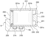
회전자 홀더(200)는, 회전자(2)의 취급액과의 접촉에 기인하는, 회전자(2)의 부식을 방지한다. 회전자 홀더(200)는, 회전자(2)를 수용하는, 프레스 성형된 환상의 수용부(201)와, 수용부(201)를 폐쇄하는 환상의 폐색판(202)을 구비하고 있다. 수용부(201)는, 환상의 오목 형상을 갖고 있고, 중심선 CL을 중심으로 하여, 임펠러(1)와 동심상으로 배치되어 있다. 예를 들어, 수용부(201)는, 딥 드로잉 성형에 의해 제조되어도 된다.The
수용부(201)는, 임펠러(1)의 측판(11)에 고정(접합)되어 있다. 일 실시 형태에서는, 수용부(201)는, 측판(11)에 용접되어 있다. 수용부(201)를 임펠러(1)에 용이하게 고정하기 위해, 임펠러(1) 및 수용부(201)는, 동일한 재료로 구성하는 것이 바람직하다.The receiving
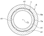
도 36은 회전자 홀더의 확대도이다. 도 36에 도시한 바와 같이, 취급액의, 수용부(201)와 폐색판(202) 사이의 간극으로부터의 침입을 방지하기 위해, 회전자 홀더(200)는, 수용부(201)와 폐색판(202) 사이에 배치된 시일 부재(예를 들어, O링)(205)를 구비하고 있다. 시일 부재(205)는, 그 탄성력에 의해, 폐색판(202)을 수용부(201)에 고정한다.Figure 36 is an enlarged view of the rotor holder. As shown in FIG. 36, in order to prevent the handling liquid from entering from the gap between the
일 실시 형태에서는, 폐색판(202)은, 기계적인 삽입 방법에 의해, 회전자 홀더(200)에 삽입되어도 된다. 기계적인 삽입 방법의 일례로서, 폐색판(202)의, 회전자 홀더(200)로의 압입을 들 수 있다. 기계적인 삽입 방법의 다른 예로서, 회전자 홀더(200)를 가열한 후에, 열팽창한 회전자 홀더(200)에 폐색판(202)을 삽입해도 된다(수축 끼워맞춤). 이 경우, 회전자(2)의 자력에 대한 열 영향(즉, 열감자)을 경감하기 위해, 폐색판(202)을 회전자 홀더(200)에 삽입한 후에, 회전자(2)를 착자하는 것이 바람직하다. 기계적인 삽입 방법의 다른 예로서, 냉각 끼워맞춤에 의해, 폐색판(202)을 회전자 홀더(200)에 삽입해도 된다. 기계적인 삽입 방법의 다른 예로서, 접착제에 의해, 폐색판(202)을 회전자 홀더(200)에 삽입해도 된다.In one embodiment, the blocking
회전자 홀더(200)의 수용부(201)는, 외측 환상부(231)와, 외측 환상부(231)의 반경 방향 내측에 배치된 내측 환상부(232)와, 외측 환상부(231) 및 내측 환상부(232)를 접속하는 환상의 배면부(233)를 구비하고 있다.The receiving
회전측 베어링체(6)는 회전자 홀더(200)에 장착되어 있고, 고정측 베어링체(7)는 회전측 베어링체(6)의 흡입측에 배치되어 있다(도 35 참조). 내측 환상부(232)와 회전측 베어링체(6)의 원통부(6a) 사이에는, 시일 부재(31A, 31B)가 배치되어 있다. 본 실시 형태에서는, 2개의 시일 부재가 배치되어 있지만, 시일 부재의 수는, 본 실시 형태에 한정되지는 않는다.The rotating
시일 부재(31A, 31B)를 내측 환상부(232)에 밀착시키기 위해, 내측 환상부(232)는, 회전자 홀더(200)의 프레스 성형 공정에 있어서, 매끄럽게 가공된다. 이와 같이, 프레스 성형 공정을 거침으로써, 시일 부재(31A, 31B)를 내측 환상부(232)에 밀착시키기 위한 새로운 추가 공정을 생략할 수 있다.In order to bring the
수용부(201)(보다 구체적으로는, 외측 환상부(231) 및 내측 환상부(232))는 회전측 베어링체(6)의 원통부(6a)와 평행하게 연장되어 있고, 원통부(6a)는 회전자 홀더(200)의 내측 환상부(232)의 반경 방향 내측에 배치되어 있다. 회전측 베어링체(6)의 플랜지부(6b)는, 폐색판(202)과 평행하게 연장되어 있고, 폐색판(202)에 인접하여 배치되어 있다.The receiving portion 201 (more specifically, the outer
수용부(201)의 내부에 공기가 존재하고 있는 경우, 수용부(201) 내의 공기의 팽창에 기인하여 폐색판(202)이 수용부(201)로부터 이격되는 방향으로 이동할 우려가 있다. 본 실시 형태에서는, 폐색판(202)에 인접하는 회전측 베어링체(6)의 플랜지부(6b)는, 폐색판(202)의 이동을 제한할 수 있다.If air exists inside the
일 실시 형태에서는, 수용부(201) 내의 공기 팽창량을 저감하기 위해, 회전자 홀더(200)는, 수용부(201)에 충전된 충전제(예를 들어, 그리스, 포팅재, 접착제 등)를 구비해도 된다.In one embodiment, in order to reduce the amount of air expansion in the
수용부(201)는, 회전측 베어링체(6)에 접촉하는 외면(201a)과, 회전자(2)에 접촉하는 내면(201b)과, 내면(201b)의 코너부에 형성된 각면(201c)을 갖고 있다. 상술한 바와 같이, 회전자 홀더(200)는, 프레스 성형품이기 때문에, 각면(201c)은 매끄러운 곡면이다. 한편, 회전자(2)는, 철판의 펀칭품인 적층 코어를 적층함으로써 제조되기 때문에, 회전자(2)는 예리한 코너부를 갖고 있다.The receiving
따라서, 회전자(2)를 수용부(201)에 삽입해도, 회전자(2)의 예리한 코너부가 매끄러운 각면(201c)에 접촉해 버려, 회전자(2)의 전체는 배면부(233)에 밀착할 수 없다. 결과적으로, 작업자는, 회전자(2)를 회전자 홀더(200)에 대하여, 확실하게 위치 결정할 수 없어, 회전자(2)를 회전자 홀더(200)에 안정적으로 수용할 수 없을 우려가 있다.Therefore, even if the
따라서, 회전자 홀더(200)는, 수용부(201)와 회전자(2) 사이에 배치된 스페이서(203)를 구비하고 있다. 도 36에 도시한 실시 형태에서는, 스페이서(203)는, 배면부(233)와 회전자(2) 사이에 배치된 심이다. 스페이서(203)를 배치함으로써, 회전자(2)의, 각면(201c)으로의 접촉을 방지할 수 있다. 결과적으로, 회전자(2)는 스페이서(203)에 밀착하여, 회전자 홀더(200)에 수용되기 때문에, 작업자는, 회전자(2)를 회전자 홀더(200)에 대하여, 확실하게 위치 결정할 수 있다. 이와 같은 구성에 의해, 작업자는, 회전자(2)를 회전자 홀더(200)에 안정적으로 수용할 수 있다.Accordingly, the
도 37은 스페이서의 다른 실시 형태를 도시하는 도면이다. 도 37에 도시한 바와 같이, 회전자 홀더(200)는, 수용부(201)와 회전자(2) 사이에 배치된 스페이서(210)를 구비해도 된다. 도 37에 도시한 실시 형태에서는, 스페이서(210)는, 회전자 홀더(200)의 배면부(233)로부터 돌출된 돌기이다.Fig. 37 is a diagram showing another embodiment of a spacer. As shown in FIG. 37, the
회전자(2)의 회전자 홀더(200)로의 체결 방법은, 예를 들어 접착제에 의한 체결 방법, 수축 끼워맞춤에 의한 체결 방법, 냉각 끼워맞춤에 의한 체결 방법을 들 수 있다. 회전자(2) 및/또는 회전자 홀더(200)의 온도 변화를 수반하는 체결 방법(예를 들어, 수축 끼워맞춤이나 냉각 끼워맞춤 등)을 채용하는 경우, 회전자(2) 및 회전자 홀더(200)의 치수를 적절하게 결정할 필요가 있다. 따라서, 간이한 체결 방법으로서, 상온에서의 체결 방법을 채용하는 것이 바람직하다.Methods of fastening the
도 38은 회전자 홀더에 삽입된 회전자를 도시하는 도면이다. 도 38에 도시한 바와 같이, 내측 환상부(232)와 접촉하는 회전자(2)의 내면(230)은, 다각 형상(본 실시 형태에서는, 8각형)을 갖고 있다. 회전자(2)의 내면(230)은 다각 형상을 갖고 있기 때문에, 회전자(2)를 회전자 홀더(200)에 상온에서 삽입하는 경우에는, 회전자 홀더(200)의 내측 환상부(232)는, 회전자(2)의 내면(230)에 선접촉할 수 있다.Fig. 38 is a diagram showing a rotor inserted into a rotor holder. As shown in FIG. 38, the
이와 같은 접촉에 의해, 회전자(2)의 전체가 회전자 홀더(200)의 내측 환상부(232)에 접촉하는 것을 방지할 수 있다. 따라서, 회전자(2)를 회전자 홀더(200)에 압입해도, 회전자(2)의 회전자 홀더(200)와의 접촉 면적을 저감할 수 있고, 결과적으로, 회전자 홀더(200)의 변형을 방지할 수 있다.Such contact can prevent the
도 39는 회전자 홀더에 삽입된 회전자를 도시하는 도면이다. 도 39에 도시한 바와 같이, 내측 환상부(232)는, 회전자(2)와의 접촉 부위에 형성된 복수의 돌기부(235)를 가져도 된다. 내측 환상부(232)의 돌기부(235)는, 회전자(2)의 내면(230)에 대향하고 있고, 회전자(2)는, 돌기부(235)에 접촉하고 있다. 이와 같은 구성에 의해서도, 회전자(2)의 회전자 홀더(200)와의 접촉 면적을 저감할 수 있고, 결과적으로, 회전자 홀더(200)의 변형을 방지할 수 있다.Figure 39 is a diagram showing a rotor inserted into a rotor holder. As shown in FIG. 39, the inner
도 35로 되돌아가, 모터 펌프 MP는, 고정자(3)를 수용하고, 또한 고정자(3)와 일체적으로 수지 몰드 성형된 고정자 케이싱(20)을 구비하고 있다. 도 35에 도시한 바와 같이, 고정자(3)는, 고정자 코어(3a)와, 절연재(220)를 통해, 고정자 코어(3a)에 감긴 코일(3b)을 구비하고 있다. 절연재(220)의 일례로서, 절연지, 수지 등을 들 수 있다. 고정자 케이싱(20)을 구성하는 수지는, 절연성을 갖고, 또한 열전도성이 우수한 재료(포팅재와 마찬가지의 재료)로 구성되어 있다.Returning to Fig. 35, the motor pump MP accommodates the
모터 펌프 MP는, 고정자 케이싱(20)의 외주면을 덮고, 또한 고정자(3)와 접촉하는 모터 프레임(221)을 구비하고 있다. 모터 프레임(221)은, 코일(3b)로부터 연장되는 전력선(105) 및 신호선(106)이 통과하는 통과 구멍(242)을 갖고 있다. 모터 프레임(221)은, 열전도성이 우수한 재료(예를 들어, 금속 재료)로 구성되어 있다. 이와 같이, 고정자(3)는, 열전도성이 우수한 고정자 케이싱(20)으로 덮여 있고, 또한 열전도성이 우수한 모터 프레임(221)에 접촉하고 있다. 따라서, 고정자(3)의 코일(3b)로부터 발해지는 열은, 고정자 케이싱(20) 및 모터 프레임(221)을 통해, 외부로 방출된다.The motor pump MP has a
흡입 케이싱(21) 및 토출 케이싱(22)과 고정자 케이싱(20) 사이에는, 취급액의 외부로의 누출을 방지하는 시일 부재(예를 들어, O링)(241)가 배치되어 있다. 고정자 케이싱(20)은, 시일 부재(241)가 장착되는 시일 홈(229)을 갖고 있다.A sealing member (for example, an O-ring) 241 is disposed between the
고정자 케이싱(20)은, 수지를 금형에 유입함으로써 성형된다. 금형에 미리 시일 홈(229)에 상당하는 돌기를 형성함으로써, 고정자 케이싱(20)을 제조한 후, 시일 홈(229)을 새롭게 형성하는 공정을 생략할 수 있다. 일 실시 형태에서는, 흡입 케이싱(21) 및 토출 케이싱(22)에 시일 부재(241)가 장착되는 시일 홈(도시 생략)을 형성해도 된다.The
본 실시 형태에서는, 고정자 케이싱(20)과, 복귀 블레이드(30)와, 복귀 블레이드(30)에 고정된 구획판(240)은, 수지 몰드 성형에 의해 제조된 일체 성형 부재이다. 복귀 블레이드(30)는, 유로로서의 특유의 비선형 형상을 갖는 경우가 있다. 본 실시 형태에 따르면, 금형에 수지를 유입하는 수지 몰드 성형을 채용함으로써, 고정자 케이싱(20), 복귀 블레이드(30), 및 구획판(240)을 일체적으로, 용이하게 대량으로 제조할 수 있다.In this embodiment, the
일 실시 형태에서는, 코일(3b)로부터의 방열성을 향상시키기 위해, 고정자 케이싱(20)은, 고정자 코어(3a) 및 포팅재로 덮인 코일(3b)을 덮어도 된다. 이와 같이, 코일(3b)을 포팅재로 덮음으로써, 포팅재는, 코일(3b)을 구성하는 선재간에 들어가기 때문에, 코일(3b)의 방열성을 향상시킬 수 있다. 이 상태에서, 또한 고정자 코어(3a) 및 코일(3b)을 고정자 케이싱(20)을 구성하는 수지로 덮음으로써, 고정자(3)의 방열성을 더욱 향상시킬 수 있다.In one embodiment, in order to improve heat dissipation from the
고정자 케이싱(20)을 구성하는 수지의 일례로서, 상온에서의 유동성이 우수한 2액 혼합 경화형의 수지(예를 들어, 디시클로펜타디엔 수지) 또는 가열 경화형의 수지(예를 들어, 에폭시 수지)를 들 수 있다. 일 실시 형태에서는, 첨가물로서의 섬유를 수지에 섞음으로써, 고정자 케이싱(20)의 강도를 향상시킬 수 있다. 일 실시 형태에서는, 첨가물로서, 열전도성이 높은 재료를 섞음으로써, 고정자 케이싱(20)의 열전도성의 향상을 실현할 수 있다. 이들 섬유 및 열전도성이 높은 재료의 양쪽을 첨가물로서, 고정자 케이싱(20)을 구성하는 수지에 섞어도 된다.As an example of the resin constituting the
도 40은 임펠러의 다른 실시 형태를 도시하는 도면이다. 도 40에 도시한 바와 같이, 모터 펌프 MP는, 회전자 홀더(200)가 일체적으로 성형된 수지 몰드 성형품인 임펠러(1)를 구비하고 있다. 임펠러(1)는, 주판(10), 측판(11), 및 날개(12)가 일체적으로 성형된 수지제이다. 일 실시 형태에서는, 첨가물로서의 섬유를 수지에 섞음으로써, 임펠러(1)의 강도를 향상시킬 수 있다.Figure 40 is a diagram showing another embodiment of an impeller. As shown in FIG. 40, the motor pump MP is equipped with an
회전자 홀더(200)는, 회전자(2)를 수용하는, 수지 몰드 성형된 환상의 수용부(251)와, 수용부(251)를 폐쇄하는 링 홀더(252)를 구비하고 있다. 임펠러(1) 및 회전자 홀더(200)의 수용부(251)는, 일체적으로 성형된 수지제이다.The
링 홀더(252)는, 프레스 성형된 내부식성을 갖는 재료(예를 들어, 스테인리스강)로 구성되어 있다. 링 홀더(252) 및 회전자(2)는, 수축 끼워맞춤, 냉각 끼워맞춤, 압입 등의 기계적 방법에 의해, 체결된다. 일 실시 형태에서는, 링 홀더(252) 및 회전자(2)는, 접착제에 의해 체결되어도 된다.The
회전자(2)를 링 홀더(252)에 체결하는 경우에는, 회전자(2)의 압입 하중을 저감하기 위해, 링 홀더(252)와 접촉하는 회전자(2)의 내면(230)은 다각 형상을 가져도 되고(도 38 참조), 링 홀더(252)는 회전자(2)와의 접촉 부위에 형성된 복수의 돌기부(235)를 가져도 된다(도 39 참조).When fastening the
도 41은 회전자 홀더의 확대도이다. 도 41에 도시한 바와 같이, 링 홀더(252)는, L자상의 단면 형상을 갖는 링부(253)와, 링부(253)로부터 꺾여 구부러진 절곡부(254)를 구비하고 있다. 프레스 성형품인 링 홀더(252)의 링부(253)는, 그 절곡 부분에 형성된 매끄러운 각면(257)을 갖고 있다.Figure 41 is an enlarged view of the rotor holder. As shown in FIG. 41, the
본 실시 형태에 있어서도, 회전자(2) 및 베어링(5)은, 임펠러(1)의 흡입측 영역(도 1 참조)에 배치되어 있다. 회전측 베어링체(6)는, 링 홀더(252)에 장착되어 있고, 고정측 베어링체(7)는, 회전측 베어링체(6)의 흡입측에 배치되어 있다. 시일 부재(31A, 31B)는, 링 홀더(252)의 링부(253)와 회전측 베어링체(6)의 원통부(6a) 사이에 배치되어 있다. 본 실시 형태에 있어서도, 링부(253)는, 프레스 성형되기 때문에, 시일 부재(31A, 31B)를 링부(253)에 밀착시키기 위한 새로운 추가 공정을 생략할 수 있다.Also in this embodiment, the
상술한 바와 같이, 회전자(2)는, 예리한 코너부를 갖고 있다. 따라서, 회전자(2)를 링 홀더(252)에 장착해도, 회전자(2)의 예리한 코너부가 매끄러운 각면(257)에 접촉해 버리고, 결과적으로, 작업자는, 회전자(2)를 회전자 홀더(200)에 안정적으로 수용할 수 없을 우려가 있다.As described above, the
따라서, 회전자 홀더(200)는, 링 홀더(252)와 회전자(2) 사이에 배치된 스페이서(260)를 구비하고 있다. 도 41에 도시한 실시 형태에서는, 스페이서(260)는, 링 홀더(252)와 회전자(2) 사이에 배치된 심이다. 일 실시 형태에서는, 스페이서(260)는, 링 홀더(252)로부터 돌출된 돌기(도시 생략)여도 된다(도 37 참조).Accordingly, the
회전자 홀더(200)를 제조하는 경우에는, 링 홀더(252)와, 링 홀더(252)에 장착된 회전자(2)를 금형에 세트한 상태에서, 금형에 수지를 유입한다. 이와 같은 제조 방법에 의해, 회전자 홀더(200)의 수용부(251)를 구성하는 수지는, 회전자(2)를 둘러싸고, 결과적으로, 수용부(251)는, 회전자(2)를 시일한다.When manufacturing the
금형에 유입되는 수지는 고온이다. 따라서, 링 홀더(252)에 장착된 회전자(2)에 고온의 수지를 접촉시키면, 회전자(2)는 열감자되어 버린다. 따라서, 회전자 홀더(200)를 제조한 후에, 회전자(2)를 착자할 필요가 있다.The resin flowing into the mold is high temperature. Therefore, when the
본 실시 형태에서는, 회전자 홀더(200)의 수용부(251) 및 임펠러(1)는, 수지 몰드 성형에 의해 제조된 일체 성형 부재이다. 임펠러(1)는, 복귀 블레이드(30)와 마찬가지로, 유로로서의 특유의 비선형 형상을 갖는 경우가 있다. 본 실시 형태에 따르면, 금형에 수지를 유입하는 수지 몰드 성형을 채용함으로써, 회전자 홀더(200)의 수용부(251) 및 임펠러(1)를 일체적으로, 용이하게 대량으로 제조할 수 있다.In this embodiment, the
링 홀더(252)는, 수용부(251)와의 접속 부위에 형성된 회전 방지 구조를 갖고 있다. 모터 펌프 MP의 운전에 의해, 회전자(2)의 회전 토크는, 임펠러(1)에 전달된다. 링 홀더(252)는, 회전 방지 구조를 갖고 있기 때문에, 임펠러(1)가 회전해도, 링 홀더(252)는, 수용부(251)에 대하여 상대적으로 회전하지 않는다. 이하, 회전 방지 구조의 구체적인 구성에 대하여, 설명한다.The
도 41에 도시한 바와 같이, 수용부(251)는, 회전자(2)의 대부분을 둘러싸는 본체부(255)와, 본체부(255)로부터 꺾여 구부러진 절곡부(256)를 구비하고 있다. 링 홀더(252)의 링부(253)는, 수용부(251)(보다 구체적으로는, 절곡부(256))의 일부가 매립된 매립 구멍(253a)을 갖고 있다. 이 매립 구멍(253a)은, 링 홀더(252)의 주위 방향을 따라서 복수 형성되어 있다.As shown in FIG. 41, the
절곡부(256)의 일부를 매립 구멍(253a)에 매립함으로써, 링 홀더(252) 및 수용부(251)가 서로 강고하게 체결된다. 이 매립은, 회전자 홀더(200)의 제조 시에, 수지를 금형에 유입함으로써, 행해진다.By embedding part of the
마찬가지로, 링 홀더(252)의 절곡부(254)는, 수용부(251)의 본체부(255)의 일부가 매립된 매립 구멍(254a)을 갖고 있다. 이 매립 구멍(254a)은, 링 홀더(252)의 주위 방향을 따라서 복수 형성되어 있다. 본체부(255)의 일부를 매립 구멍(254a)에 매립함으로써, 링 홀더(252) 및 수용부(251)는 서로 강고하게 체결된다. 이 매립은, 회전자 홀더(200)의 제조 시에, 수지를 금형에 유입함으로써, 행해진다. 본 실시 형태에 따르면, 온도 변화에 수반되는 회전자(2)와 회전자 홀더(200)의 선팽창의 차에 의해, 회전자 홀더(200)가 회전자(2)로부터 박리되는 것을 기계적으로 억제할 수 있다.Similarly, the
도 42는 회전 방지 구조의 다른 실시 형태를 도시하는 도면이다. 도 42에 도시한 바와 같이, 회전 방지 구조는, 일본어 コ자상으로 꺾여 구부러지는 절곡부(253b, 254b)여도 된다. 보다 구체적으로는, 링 홀더(252)의 링부(253)는, 일본어 コ자상으로 꺾여 구부러지는 절곡부(253b)를 갖고 있고, 마찬가지로, 절곡부(254)는, 일본어 コ자상으로 꺾여 구부러지는 절곡부(254b)를 갖고 있다. 이와 같은 구조에 의해서도, 링 홀더(252) 및 수용부(251)는 서로 강고하게 체결된다. 또한, 도 41에 도시한 실시 형태와 도 42에 도시한 실시 형태를 조합해도 된다.Figure 42 is a diagram showing another embodiment of the rotation prevention structure. As shown in Fig. 42, the anti-rotation structure may be
일 실시 형태에서는, 회전 방지 구조는, 링부(253) 및 절곡부(254)의 각각에 형성된 기어상의 커팅 홈(도시 생략)이어도 된다. 이 커팅 홈은, 링 홀더(252)의 주위 방향을 따라서 복수 형성되어 있다.In one embodiment, the rotation prevention structure may be a cutting groove (not shown) on a gear formed in each of the
일 실시 형태에서는, 수용부(251) 및 링 홀더(252)의 밀착성의 향상을 위해, 미리 링 홀더(252)의 표면에 프라이머를 도포하여, 링 홀더(252)의 표면의 산화물을 제거하는 프라이머 처리를 실시해도 된다.In one embodiment, in order to improve the adhesion between the receiving
도 40 내지 도 42에 도시한 실시 형태에 있어서도, 고정자 케이싱(20)은, 도 35 내지 도 39에 도시한 실시 형태에 관한 고정자 케이싱(20)과 마찬가지의 구조를 갖고 있다. 보다 구체적으로는, 모터 펌프 MP는, 고정자(3)를 수용하고, 또한 고정자(3)와 일체적으로 수지 몰드 성형된 고정자 케이싱(20)과, 고정자 케이싱(20)의 외주면을 덮고, 또한 고정자(3)와 접촉하는 모터 프레임(221)을 구비하고 있다.Also in the embodiments shown in FIGS. 40 to 42, the
도 43은 모터 펌프의 다른 실시 형태를 도시하는 도면이다. 본 실시 형태에 있어서, 상술한 실시 형태와 동일 또는 상당하는 구성 요소에는, 동일한 부호를 붙이고 중복된 설명을 생략한다.Figure 43 is a diagram showing another embodiment of a motor pump. In this embodiment, components that are the same or equivalent to those in the above-described embodiment are given the same reference numerals and redundant descriptions are omitted.
도 43에 도시한 바와 같이, 모터 펌프 MP는, 흡입구(21a) 측에 배치된 제1 임펠러(1A)와, 토출구(22a) 측에 배치된 제2 임펠러(1B)를 적어도 포함하는, 복수의 임펠러(1)를 구비하고 있다. 일 실시 형태에서는, 제1 임펠러(1A)와 제2 임펠러(1B) 사이에는, 적어도 1개의 임펠러(1)가 배치되어도 된다. 회전자(2)를 보유 지지하는 회전자 홀더(200)는 제1 임펠러(1A)에 고정되어 있고, 회전자(2)의 반경 방향 외측에는, 수지제의 고정자 케이싱(20)에 수용된 고정자(3)가 배치되어 있다.As shown in FIG. 43, the motor pump MP includes at least a
도 43에 도시한 바와 같이, 회전자 홀더(200)에 수용된 회전자(2)는, 제1 임펠러(1A)에 고정되어 있기 때문에, 회전자(2)의 회전력은, 제1 임펠러(1A)에 작용한다. 제1 임펠러(1A)에 작용하는 회전력은, 연통축(270)을 통해 제2 임펠러(1B)에 전달된다. 이와 같이, 제1 임펠러(1A)는, 회전자(2)의 회전력을 모두 받기 때문에, 제1 임펠러(1A)에 작용하는 하중이 커져, 제1 임펠러(1A)가 파손될 우려가 있다.As shown in FIG. 43, since the
따라서, 제1 임펠러(1A)는, 다른 임펠러(1)(본 실시 형태에서는, 제2 임펠러(1B))보다도 높은 강도를 갖는 것이 바람직하다. 또한, 본 실시 형태에 관한 모터 펌프 MP의 고양정을 실현하기 위해서는, 제1 임펠러(1A)는 높은 강도를 갖는 것이 바람직하다. 이와 같이, 복수의 임펠러(1)를 구비하는 모터 펌프 MP는, 콤팩트한 구조를 가질 뿐만 아니라, 높은 강도를 갖는 구조를 갖는 것이 바람직하다. 이와 같은 구조에 의해, 모터 펌프 MP는, 안정적으로 운전할 수 있다.Therefore, the
따라서, 본 실시 형태에 관한 모터 펌프 MP는, 콤팩트한 구조를 가질 뿐만 아니라, 안정적으로 운전할 수 있는 구조를 갖고 있다. 이하, 모터 펌프 MP의 구조에 대하여, 도면을 참조하여 설명한다.Therefore, the motor pump MP according to this embodiment not only has a compact structure, but also has a structure that can be operated stably. Hereinafter, the structure of the motor pump MP will be described with reference to the drawings.
제1 임펠러(1A)는, 제1 베어링(5)에 의해 지지되어 있고, 제1 임펠러(1A)에는, 연통축(270)이 접속되어 있다. 제2 임펠러(1B)는, 연통축(270)에 접속되어 있다. 모터 펌프 MP는, 제1 임펠러(1A)와 제2 임펠러(1B) 사이에 배치된 중간 케이싱(275)을 구비하고 있고, 중간 케이싱(275)에는, 라이너 링(276)이 접속되어 있다. 라이너 링(276)은, 제2 임펠러(1B)에 흡입된 취급액의 역류를 억제하는 링 부재이다.The
도 43에 도시한 실시 형태에서는, 중간 케이싱(275)은, 고정자 케이싱(20)과는 별도의 부재로 구성되어 있지만, 중간 케이싱(275) 및 고정자 케이싱(20)은, 동일 부재로 구성되어도 된다. 본 실시 형태에서는, 중간 케이싱(275)에 고정된 복귀 블레이드(30)는, 제1 임펠러(1A)로부터 토출된 취급액을 제2 임펠러(1B)로 안내하는 안내 블레이드로서의 역할도 한다. 복귀 블레이드(및 안내 블레이드)(30)는, 제1 임펠러(1A)의 임펠러(1A)의 원심력에 의해 발생한 취급액의 유속을 효율적으로 압력으로 변환하여, 제1 임펠러(1B)의 액체 입구까지 안내할 수 있다.In the embodiment shown in FIG. 43, the
토출 케이싱(22)은, 복귀 블레이드(30)와, 복귀 블레이드(30)에 고정된 구획판(245)을 일체적으로 구성하고 있다. 즉, 토출 케이싱(22), 복귀 블레이드(30), 및 구획판(245)은, 일체 성형 부재이다. 이들 일체적으로 구성된 토출 케이싱(22), 복귀 블레이드(30), 및 구획판(245)은, 수지 몰드 성형에 의해 일체적으로 구성되어도 된다. 일 실시 형태에서는, 토출 케이싱(22), 복귀 블레이드(30), 및 구획판(245)은, 별도의 부재여도 된다. 토출 케이싱(22)에 고정된 복귀 블레이드(30)도 중간 케이싱(275)에 고정된 복귀 블레이드(30)와 마찬가지의 역할을 한다.The
도 44는 모터 펌프의 다른 실시 형태를 도시하는 도면이다. 도 43에 도시한 실시 형태에서는, 회전자 홀더(200)는, 도 35에 도시한 실시 형태에 관한 회전자 홀더(200)와 마찬가지의 구조를 갖고 있다. 도 44에 도시한 바와 같이, 회전자 홀더(200)는, 도 40에 도시한 실시 형태에 관한 회전자 홀더(200)와 마찬가지의 구조를 가져도 된다.Figure 44 is a diagram showing another embodiment of a motor pump. In the embodiment shown in FIG. 43, the
도 45는 제1 임펠러 및 제2 임펠러의 확대도이다. 도 45에 도시한 바와 같이, 제1 임펠러(1A)의 보스부(281)는, 제2 임펠러(1B)의 보스부(282)보다도 큰 사이즈를 갖고 있다. 보스부(281)는 제1 임펠러(1A)의 연통축(270)과의 접속 부위이며, 보스부(282)는 제2 임펠러(1B)의 연통축(270)과의 접속 부위이다.Figure 45 is an enlarged view of the first impeller and the second impeller. As shown in FIG. 45, the
도 45에 도시한 실시 형태에서는, 보스부(281)의 중심선 CL 방향의 길이 L1은, 보스부(282)의 중심선 CL 방향의 길이 L2보다도 길다. 상술한 바와 같이, 회전자(2)의 회전에 수반하여 제1 임펠러(1A)에 작용하는 하중은, 제2 임펠러(1B)에 작용하는 하중보다도 크다. 본 실시 형태에 따르면, 제1 임펠러(1A)의 보스부(281)는, 제2 임펠러(1B)의 보스부(282)보다도 큰 사이즈를 갖고 있기 때문에, 제1 임펠러(1A)는, 회전자(2)의 회전력을 충분히 받을 수 있다. 결과적으로, 모터 펌프 MP는, 제1 임펠러(1A)의 파손을 방지할 수 있다.In the embodiment shown in FIG. 45, the length L1 of the
도 45에 도시한 바와 같이, 모터 펌프 MP는, 제1 임펠러(1A)와 제2 임펠러(1B) 사이에 소정의 거리를 형성하는 슬리브(280)를 구비하고 있다. 슬리브(280)는, 제1 임펠러(1A)와 제2 임펠러(1B) 사이에 배치되어 있다. 슬리브(280)를 배치함으로써, 작업자는, 제1 임펠러(1A)와 제2 임펠러(1B) 사이의 거리를 용이하게 관리할 수 있다.As shown in FIG. 45, the motor pump MP is provided with a
제1 임펠러(1A) 및 제2 임펠러(1B)의 각각은, 동력 전달 구조(키 구조, 2모따기 구조, 스플라인 구조 등)를 갖고 있고, 이와 같은 구조에 의해 연통축(270)에 접속되어 있다.Each of the
본 실시 형태에서는, 제1 임펠러(1A) 및 제2 임펠러(1B)의 각각은, 연통축(270)에 체결된 체결구(예를 들어, 너트)(273)에 의해 연통축(270)에 고정되어 있다. 제1 임펠러(1A)와 제2 임펠러(1B) 사이에는, 슬리브(280)가 배치되어 있고, 체결구(273)와 제2 임펠러(1B) 사이에는, 회전측 베어링체(272)(후술함)가 배치되어 있다.In this embodiment, each of the
따라서, 체결구(273)를 체결함으로써, 슬리브(280)는 제1 임펠러(1A)에 압박 접촉되고, 회전측 베어링체(272)는 제2 임펠러(1B)에 압박 접촉된다. 결과적으로, 제1 임펠러(1A)는, 연통축(270)의 선단부(270a)와 슬리브(280) 사이에 끼워지고, 제2 임펠러(1B)는, 슬리브(280)와 회전측 베어링체(272) 사이에 끼워진다. 이와 같이 하여, 제1 임펠러(1A) 및 제2 임펠러(1B)는, 연통축(270)에 강고하게 고정된다.Therefore, by fastening the
본 실시 형태에서는, 연통축(270)의 선단부(270a)는 흡입측에 배치되어 있고, 체결구(273)는 토출측에 배치되어 있다. 일 실시 형태에서는, 연통축(270)의 선단부(270a)는, 육각 머리 또는 육각 구멍을 가져도 된다. 이와 같은 구조에 의해, 작업자는, 선단부(270a)를 고정한 상태에서, 체결구(273)를 연통축(270)에 강고하게 체결할 수 있다.In this embodiment, the
도 46은 제1 임펠러 및 제2 임펠러와, 연통축의 접속 구조의 다른 실시 형태를 도시하는 도면이다. 도 46에 도시한 바와 같이, 모터 펌프 MP는, 제1 임펠러(1A) 및 제2 임펠러(1B)의 각각을 연통축(270)에 체결하는 콜릿(285, 286)을 구비하고 있다. 콜릿(285, 286)은, 동일한 구조를 갖고 있기 때문에, 이하, 콜릿(285)의 구조에 대하여 설명한다.Fig. 46 is a diagram showing another embodiment of the connection structure between the first impeller and the second impeller and the communication shaft. As shown in FIG. 46, the motor pump MP is provided with
콜릿(285)은, 끝이 가늘어지는 테이퍼 형상을 갖는 통 부재이며, 중심선 CL 방향으로 연장되는 노치(도시 생략)를 갖고 있다. 제1 임펠러(1A)의 배면측으로부터 콜릿(285)을 제1 임펠러(1A)에 삽입함으로써, 콜릿(285)은 제1 임펠러(1A)에 파고 들어가, 제1 임펠러(1A)는 연통축(270)에 체결된다. 마찬가지로, 콜릿(286)을 제2 임펠러(1B)에 삽입함으로써, 콜릿(286)은 제2 임펠러(1B)에 파고 들어가, 제2 임펠러(1B)는 연통축(270)에 체결된다. 이와 같은 구조에 의해, 제1 임펠러(1A) 및 제2 임펠러(1B)의 각각은, 보다 강고하게 연통축(270)에 체결된다.The
제1 임펠러(1A)를 연통축(270)에 체결하였을 때, 콜릿(285)의 선단 부분과 연통축(270)의 선단부(270a) 사이에는, 간극이 형성된다. 제2 임펠러(1B)를 연통축(270)에 체결하였을 때, 콜릿(286)의 선단 부분과 슬리브(280) 사이에는, 간극이 형성된다.When the
도 43(및 도 44)으로 되돌아가, 모터 펌프 MP는, 제2 임펠러(1B)의 후단에 배치된, 연통축(270)을 회전 가능하게 지지하는 제2 베어링(플레인베어링)(277)을 구비하고 있다. 제2 베어링(277)은, 연통축(270) 측에 배치된 회전측 베어링체(272)와, 토출 케이싱(22) 측에 배치된 고정측 베어링체(271)를 구비하고 있다.Returning to Figure 43 (and Figure 44), the motor pump MP includes a second bearing (plain bearing) 277 that rotatably supports the
회전측 베어링체(272)는, 연통축(270)에 장착된 회전측 원통체이며, 고정측 베어링체(271)는, 토출 케이싱(22)에 설치되며, 또한 회전측 원통체로서의 회전측 베어링체(272)를 둘러싸는 고정측 원통체이다. 토출 케이싱(22)의 구획판(245)은, 고정측 베어링체(271)를 지지하는 베어링 지지부(246)를 갖고 있다. 고정측 베어링체(271)는 베어링 지지부(246)에 고정되어 있다. 고정측 베어링체(271)와 회전측 베어링체(272) 사이에는, 약간의 간극이 형성되어 있다.The rotating
제2 베어링(277)의 재료의 일례로서, 세라믹 또는 수지를 들 수 있다. 제1 임펠러(1A)의 회전과 함께 연통축(270)이 회전하면, 고정측 베어링체(271)와 회전측 베어링체(272) 사이에는, 액체가 들어가고, 고정측 베어링체(271)는, 이 액체의 동압에 의해 회전측 베어링체(272)를 지지한다.Examples of the material of the
제2 베어링(277)을 배치함으로써, 연통축(270)은, 제1 임펠러(1A)에 고정된 제1 베어링(5)뿐만 아니라, 제2 베어링(277)에 의해서도 지지된다. 복수의 임펠러(1)가 접속된 연통축(270)은, 그 중심선 CL 방향의 길이가 길어진다. 제1 베어링(5) 및 제2 베어링(277)을 구비한 모터 펌프 MP는, 연통축(270)의 장축화에 수반되는 연통축(270)의 축 흔들림을 억제하여, 결과적으로, 안정적으로 운전할 수 있다.By disposing the
모터 펌프 MP의 조립 수순에 대하여 설명한다. 먼저, 제1 임펠러(1A)와 연통축(270)을 체결한다(공정 1). 그 후, 중간 케이싱(275)(도 43 및 도 44 참조)을 연통축(270)에 삽입하고(공정 2), 슬리브(280)를 연통축(270)에 삽입한다(공정 3). 이어서, 제2 임펠러(1B)를 연통축(270)에 삽입하고, 이들 제2 임펠러(1B) 및 연통축(270)을 체결한다(공정 4). 그 후, 회전측 베어링체(272)를 연통축(270)에 삽입하고(공정 5), 토출 케이싱(22)을 고정자 케이싱(20)에 체결한다(공정 6). 그 후, 체결구(273)를 연통축(270)에 체결한다(공정 7).The assembly procedure for the motor pump MP will be described. First, the
일 실시 형태에서는, 작업자는, 공정 5를 행한 후, 공정 7을 행하고, 그 후, 공정 6을 행해도 된다. 그러나, 연통축(270)에 고정되는 임펠러(1)의 수가 많아짐에 따라, 연통축(270)이 기울어져 버려, 결과적으로, 연통축(270)의 위치가 중심선 CL 방향으로부터 어긋날 우려가 있다.In one embodiment, the operator may perform
따라서, 작업자는, 토출 케이싱(22)을 설치하여, 회전측 베어링체(272)와 고정측 베어링체(271)의 위치 관계를 확인하면서, 체결구(273)를 연통축(270)에 체결하는 것이 바람직하다. 본 실시 형태에 따르면, 모터 펌프 MP는, 흡입구(21a) 및 토출구(22a)가 일직선 상에 나열되는 스트레이트형 모터 펌프이기 때문에, 제2 베어링(277)에 의해 연통축(270)을 지지하면서, 체결구(273)를 연통축(270)에 체결할 수 있다.Therefore, the worker installs the
도 47은 체결구의 다른 실시 형태를 도시하는 도면이다. 도 47에 도시한 바와 같이, 체결구(290)는, 회전측 베어링체(272)보다도 작은 직경을 갖고 있다. 일 실시 형태에서는, 체결구(290)는, 회전측 베어링체(272)와 동일한 직경을 가져도 된다. 체결구(290)와 연통축(270) 사이에는, 스페이서(291)가 배치되어 있다. 체결구(290)를 연통축(270)의 단부에 형성된 나사 구멍(270b)에 삽입함으로써, 스페이서(291)는, 회전측 베어링체(272)를 제2 임펠러(1B)에 압박 접촉시킨다. 본 실시 형태에 따르면, 고정측 베어링체(271)를 삽입해도, 체결구(290)의, 고정측 베어링체(271)와의 접촉은 확실하게 방지된다.Figure 47 is a diagram showing another embodiment of a fastener. As shown in Figure 47, the
본 실시 형태에서는, 콜릿(285, 286)의 각각을 제1 임펠러(1A) 및 제2 임펠러(1B)의 각각에 삽입함으로써, 제1 임펠러(1A) 및 제2 임펠러(1B)는 연통축(270)에 충분히 체결된다. 따라서, 체결구(290)는, 회전측 베어링체(272)의 중심선 CL 방향으로의 이동을 제한할 만큼의 체결력을 갖고 있으면 된다.In this embodiment, by inserting each of the
도 48은 제2 베어링의 다른 실시 형태를 도시하는 도면이다. 도 48에 도시한 바와 같이, 회전측 베어링체(272)는 연통축(270)과 일체적으로 형성되어도 된다. 이 경우, 연통축(270)은, 회전측 베어링체(272)와 동일한 베어링 재료(예를 들어, 세라믹이나 강재 등)로 구성되어 있다. 도 48에 도시한 실시 형태에서는, 회전측 베어링체(272)와 일체적으로 형성된 연통축(270)의 주위에는, 고정측 베어링체(271)가 배치되어 있다.Figure 48 is a diagram showing another embodiment of the second bearing. As shown in FIG. 48, the rotation-
도 49는 제2 베어링의 다른 실시 형태를 도시하는 도면이다. 도 49에 도시한 실시 형태에서는, 고정측 베어링체(271)는, 토출 케이싱(22)의 베어링 지지부(246)와 일체적으로 형성되어 있다. 본 실시 형태에 있어서, 베어링 지지부(246)는, 고정측 베어링체(271)와 동일한 베어링 재료(예를 들어, 세라믹이나 강재나 수지 등)로 구성되어 있다.Fig. 49 is a diagram showing another embodiment of the second bearing. In the embodiment shown in FIG. 49, the fixed
이와 같이, 모터 펌프 MP는, 도 35 내지 도 39에 도시한 실시 형태에 관한 임펠러(1)와 동일한 구조를 갖는 제1 임펠러(1A)를 구비해도 되고, 또는 도 40 내지 도 42에 도시한 실시 형태에 관한 임펠러(1)와 동일한 구조를 갖는 제1 임펠러(1A)를 구비해도 된다. 일 실시 형태에서는, 모터 펌프 MP는, 도 1 내지 도 34에 도시한 실시 형태에 관한 임펠러(1)와 동일한 구조를 갖는 제1 임펠러(1A)를 구비해도 된다. 바꿔 말하면, 도 1 내지 도 49에 도시한 실시 형태는, 가능한 한, 조합되어도 된다.In this way, the motor pump MP may be provided with the
도 50은 상술한 실시 형태에 관한 모터 펌프에 마련된 사이드 플레이트를 도시하는 도면이다. 도 50에 도시한 바와 같이, 모터 펌프 MP는, 임펠러(1)에 의해 승압된 액체(취급액)의, 토출 케이싱(22)으로의 유출을 제한하는 사이드 플레이트(300)를 더 구비해도 된다. 도 50에 도시한 실시 형태에서는, 사이드 플레이트(300)는, 원반 형상을 갖고 있고, 복귀 블레이드(30)에 고정되어 있다.Fig. 50 is a diagram showing a side plate provided in the motor pump according to the above-described embodiment. As shown in FIG. 50, the motor pump MP may further be provided with a
사이드 플레이트(300)는, 임펠러(1)의 주판(10)과 복귀 블레이드(30) 사이에 배치되어 있다. 임펠러(1)에 의해 승압된 액체의 일부는, 복귀 블레이드(30)를 통해 사이드 플레이트(300)와 토출 케이싱(22) 사이의 간극을 통해, 토출구(22a)로부터 토출된다. 임펠러(1)에 의해 승압된 액체의 다른 부분은, 사이드 플레이트(300)와 임펠러(1)의 주판(10) 사이의 간극에 유입된다.The
임펠러(1)가 회전하면, 임펠러(1)에는, 임펠러(1)를 토출 케이싱(22) 측으로 누르는 액체의 힘(즉, 유체력)이 작용한다. 사이드 플레이트(300)와 주판(10) 사이의 간극에 유입된 액체의 흐름은, 사이드 플레이트(300)에 의해 제한되기 때문에, 승압된 액체는, 사이드 플레이트(300)와 주판(10) 사이의 간극에 체류한다. 사이드 플레이트(300)와 주판(10) 사이의 간극에 체류하는 액체는, 임펠러(1)에 작용하는 유체력을 받아내기 때문에, 임펠러(1)의, 토출 케이싱(22) 측으로의 이동은 제한된다.When the
모터 펌프 MP가 정상적으로 운전되면, 임펠러(1)에는, 토출 케이싱(22) 측으로부터 흡입 케이싱(21) 측으로의 스러스트력이 작용한다. 따라서, 임펠러(1)에 유체력이 작용해도, 임펠러(1)는, 베어링(5)에 안정적으로 보유 지지된다. 도 50에 도시한 실시 형태에서는, 도 1에 도시한 실시 형태에 관한 모터 펌프 MP에 사이드 플레이트(300)를 적용한 실시 형태에 대하여 설명하였지만, 사이드 플레이트(300)는, 도 2 내지 도 49에 도시한 실시 형태에 관한 모터 펌프 MP에도 적용 가능하다.When the motor pump MP operates normally, a thrust force acts on the
도 51은 사이드 플레이트의 다른 실시 형태이다. 도 51에 도시한 바와 같이, 사이드 플레이트(300)는, 그 중앙에 형성된 개구(300a)를 가져도 된다. 상술한 바와 같이, 사이드 플레이트(300)와 주판(10) 사이의 간극에 유입된 액체는, 사이드 플레이트(300)와 주판(10) 사이의 간극에 체류하는 경우가 있다.Figure 51 shows another embodiment of the side plate. As shown in FIG. 51, the
이 경우, 임펠러(1)의 회전에 의해, 체류하는 액체는, 선회하고, 머지않아, 발열할 우려가 있다. 개구(300a)를 사이드 플레이트(300)에 형성함으로써, 사이드 플레이트(300)와 토출 케이싱(22) 사이의 간극과, 사이드 플레이트(300)와 임펠러(1) 사이의 간극 사이에 있어서의, 액체의 순환류가 형성된다. 따라서, 사이드 플레이트(300)와 임펠러(1) 사이에 존재하는 액체는, 토출 케이싱(22) 측에 유입되어, 액체의 발열이 방지되어, 액체의 온도를 일정하게 유지할 수 있다. 또한, 개구(300a)는, 체류하는 액체에 포함되는 공기를 토출 케이싱(22) 측으로 배출하는 역할을 할 수 있다.In this case, due to the rotation of the
도 51에 도시한 실시 형태에서는, 사이드 플레이트(300)의 개구(300a)는, 중심선 CL 상에 형성된 단일의 개구이지만, 개구(300a)의 수는 본 실시 형태에 한정되지는 않는다. 사이드 플레이트(300)는, 임펠러(1)의, 토출 케이싱(22) 측으로의 이동을 제한하는 한도에 있어서, 복수의 개구(300a)를 가져도 된다.In the embodiment shown in FIG. 51, the
또한, 개구(300a)는, 액체의 순환류를 형성할 수 있으면, 반드시 중심선 CL 상에 형성될 필요는 없다. 예를 들어, 사이드 플레이트(300)는, 중심선 CL을 중심으로 동심원상으로 배치된 적어도 1개의 개구(300a)를 가져도 된다.Additionally, the
개구(300a)의 형상도 특별히 한정되지는 않고, 원 형상을 가져도 되고, 다각 형상(예를 들어, 삼각 형상 또는 사각 형상)을 가져도 된다. 개구(300a)의 크기(즉, 면적)도 마찬가지로, 사이드 플레이트(300)가 토출 케이싱(22) 측으로의 이동을 제한하는 한도에 있어서, 특별히 한정되지는 않는다.The shape of the
도 52는 모터 펌프의 다른 실시 형태를 도시하는 도면이다. 도 52에 도시한 실시 형태에서는, 모터 펌프 MP는, 모터 펌프 MP의 중심선 CL 방향에 대하여 수직인 연직 방향으로 연장되는 토출 포트(322)를 갖는 토출 케이싱(22)을 구비하고 있다. 토출 포트(322)는, 상방을 향하여 개구되는 토출구(322a)를 갖고 있고, 흡입구(21a) 및 토출구(322a)는, 서로 직교하고 있다.Figure 52 is a diagram showing another embodiment of a motor pump. In the embodiment shown in Fig. 52, the motor pump MP is provided with a
도 52에 도시한 실시 형태에서는, 모터 펌프 MP는, 흡입구(21a) 및 토출구(322a)가 직교하는, 소위 엔드 톱형 모터 펌프이다. 이와 같은 모터 펌프 MP는, 콤팩트한 구조를 갖는다. 예를 들어, 모터 펌프 MP의 설치 환경에 따라서는, 흡입구(21a) 및 토출구(22a)가 일직선 상에 나열되도록 배치된 구조를 갖는 모터 펌프 MP를 설치할 수 없는 경우가 있다. 이와 같은 경우라도, 엔드 톱형의 모터 펌프 MP는, 설치 가능하다. 이와 같이, 본 실시 형태에서는, 모터 펌프 MP를, 모든 설치 환경에 대응하여 설치할 수 있다.In the embodiment shown in FIG. 52, the motor pump MP is a so-called end-top type motor pump in which the
도 52에 도시한 바와 같이, 모터 펌프 MP는, 임펠러(1)에 의해 승압된 액체(취급액)의, 토출 포트(322)로의 유출을 제한하는 사이드 플레이트(300)를 더 구비해도 된다. 이와 같이, 사이드 플레이트(300)는, 엔드 톱형 모터 펌프 MP에도 적용 가능하다. 또한, 도 52에 도시한 실시 형태에 있어서도, 사이드 플레이트(300)는, 개구(300a)를 가져도 된다(도 51 참조).As shown in FIG. 52, the motor pump MP may further be provided with a
상술한 실시 형태는, 본 발명이 속하는 기술분야에 있어서의 통상의 지식을 가진 자가 본 발명을 실시할 수 있는 것을 목적으로 하여 기재된 것이다. 상기 실시 형태의 다양한 변형예는, 당업자라면 당연히 이룰 수 있는 것이며, 본 발명의 기술적 사상은 다른 실시 형태에도 적용할 수 있는 것이다. 따라서, 본 발명은, 기재된 실시 형태에 한정되지는 않고, 특허 청구 범위에 의해 정의되는 기술적 사상에 따른 가장 넓은 범위로 해석되는 것이다.The above-described embodiments have been described for the purpose of enabling those skilled in the art in the technical field to which the present invention pertains to practice the present invention. Various modifications to the above embodiments can naturally be made by those skilled in the art, and the technical idea of the present invention can be applied to other embodiments. Accordingly, the present invention is not limited to the described embodiments, but is to be interpreted in the widest scope according to the technical idea defined by the patent claims.
본 발명은, 모터 펌프에 이용 가능하다.The present invention can be used in motor pumps.
1, 1A, 1B, 1C: 임펠러
2: 회전자
2a: 철심
2b: 자석
3: 고정자
3a: 고정자 코어
3b: 코일
5: 베어링
6: 회전측 베어링체
6a: 원통부
6b: 플랜지부
7: 고정측 베어링체
7a: 원통부
7b: 플랜지부
10: 주판
10a: 관통 구멍
11: 측판
11a: 외연부
12: 날개
15: 흡입부
16: 본체부
17: 돌기부
17a: 외주면
17b: 내주면
20: 고정자 케이싱
20a: 내주면
21: 흡입 케이싱
21a: 흡입구
22: 토출 케이싱
22a: 토출구
25: 관통 볼트
25a: 헤드부
30: 복귀 블레이드
31: 시일 부재
32, 33: 시일 부재
40, 41, 42: 홈
41a: 양단
45: 하중 저감 구조
46: 이면 블레이드
47: 노치
50, 51: 경사면
53, 54: 경사면
60: 인버터
61: 중간 케이싱
65: 배관
70, 70A, 70B: 볼록부
71: 선단부
75: 밸런스 조정 지그(센터 서포트 조정 지그)
76: 축체
77: 고정체
80: 센터 캡
85: 밸런스 조정 지그(에지 서포트 조정 지그)
86: 서포터
87: 축부
90: 추 삽입 구멍
91: 추
100: 제어 장치
100a: 신호 수신부
100b: 기억부
100c: 제어부
101: 전류 센서
102: 단자대
105: 전력선
106: 신호선
107: 보호 커버
108: 구리 바
110: 커버
117: 돌기부
118: 장착부
120: 시일 부재
121: 시일 부재
125: 중간 케이싱
126: 연통축
127A: 시일 부재
127B: 시일 부재
128: 토출측 베어링
129: 유로
130: 선회 방지부
140: 접속관
141: 흡입 케이싱
141a: 흡입구
141b: 삽입 구멍
142: 토출 케이싱
142a: 토출구
142b: 볼트 수용부
150: 체결구
160: 주판
200: 회전자 홀더
201: 수용부
201a: 외면
201b: 내면
201c: 각면
202: 폐색판
203: 스페이서
205: 시일 부재
220: 절연재
221: 모터 프레임
229: 시일 홈
230: 내면
231: 외측 환상부
232: 내측 환상부
233: 배면부
235: 돌기부
240: 구획판
241: 시일 부재
242: 통과 구멍
245: 구획판
251: 수용부
252: 링 홀더
253: 링부
253a: 매립 구멍
253b: 절곡부
254: 절곡부
254a: 매립 구멍
254b: 절곡부
255: 본체부
256: 절곡부
260: 스페이서
270: 연통축
270a: 선단부
270b: 나사 구멍
271: 고정측 베어링체
272: 회전측 베어링체
273: 체결구
275: 중간 케이싱
276: 라이너 링
277: 제2 베어링
280: 슬리브
281: 보스부
282: 보스부
285, 286: 콜릿
290: 체결구
291: 스페이서
300: 사이드 플레이트
300a: 개구
322: 토출 포트
322a: 토출구
MP: 모터 펌프
PU: 펌프 유닛
CL: 중심선
Ra: 흡입측 영역
Rb: 토출측 영역
Rc: 중간 영역
RS: 회전축
Nt: 너트1, 1A, 1B, 1C: Impeller
2: rotor
2a: iron core
2b: magnet
3: stator
3a: stator core
3b: coil
5: Bearing
6: Rotating side bearing body
6a: cylindrical part
6b: Flange part
7: Fixed side bearing body
7a: cylindrical part
7b: Flange part
10: Abacus
10a: through hole
11: side plate
11a: outer edge
12: wings
15: suction part
16: main body
17: Protrusion
17a: outer peripheral surface
17b: If you give it to me
20: stator casing
20a: If you give it to me
21: intake casing
21a: intake port
22: Discharge casing
22a: discharge port
25: Through bolt
25a: head part
30: return blade
31: Absence of seal
32, 33: Absence of seal
40, 41, 42: Home
41a: both ends
45: Load reduction structure
46: back blade
47: notch
50, 51: slope
53, 54: slope
60: inverter
61: middle casing
65: Plumbing
70, 70A, 70B: Convex portion
71: tip
75: Balance adjustment jig (center support adjustment jig)
76: Axis
77: fixture
80: Center cap
85: Balance adjustment jig (edge support adjustment jig)
86: Supporter
87: shaft
90: Weight insertion hole
91: Chu
100: control device
100a: signal receiver
100b: memory unit
100c: control unit
101: current sensor
102: terminal block
105: power line
106: signal line
107: protective cover
108: copper bar
110: cover
117: protrusion
118: Mounting part
120: Absence of seal
121: Absence of seal
125: middle casing
126: Plumbing axis
127A: Absence of seal
127B: Absence of seal
128: Discharge side bearing
129: Euro
130: Swing prevention unit
140: connection pipe
141: intake casing
141a: intake port
141b: insertion hole
142: Discharge casing
142a: discharge port
142b: Bolt receiving portion
150: fastener
160: Abacus
200: rotor holder
201: receiving part
201a: turning away
201b: Inside
201c: each side
202: Occlusion plate
203: spacer
205: Absence of seal
220: Insulating material
221: motor frame
229: seal groove
230: Inside
231: Lateral annulus
232: medial annulus
233: back part
235: protrusion
240: partition plate
241: Absence of seal
242: Through hole
245: partition plate
251: receiving part
252: Ring holder
253: Ringbu
253a: buried hole
253b: bend part
254: bending part
254a: buried hole
254b: bend part
255: main body
256: bending part
260: spacer
270: Plumbing axis
270a: tip
270b: screw hole
271: Fixed side bearing body
272: Rotating side bearing body
273: Fastener
275: middle casing
276: Liner ring
277: second bearing
280: sleeve
281: Boss Department
282: Boss Department
285, 286: collet
290: Fastener
291: spacer
300: side plate
300a: opening
322: discharge port
322a: discharge port
MP: motor pump
PU: pump unit
CL: center line
Ra: suction side area
Rb: discharge side area
Rc: middle region
RS: rotation axis
Nt:nut
Claims (23)
상기 회전자의 반경 방향 외측에 배치된 고정자와,
상기 회전자를 보유 지지하는 회전자 홀더와,
상기 회전자 홀더가 고정된, 프레스 성형품인 임펠러를 구비하는, 모터 펌프.rotor,
a stator disposed radially outside the rotor;
a rotor holder that holds and supports the rotor;
A motor pump comprising an impeller, which is a press-molded product, to which the rotor holder is fixed.
상기 회전자 홀더는,
상기 회전자를 수용하는, 프레스 성형된 환상의 수용부와,
상기 수용부를 폐쇄하는 환상의 폐색판을 구비하고 있는, 모터 펌프.According to paragraph 1,
The rotor holder,
a press-molded annular receiving portion that accommodates the rotor;
A motor pump comprising an annular closing plate that closes the receiving portion.
상기 회전자 홀더는, 상기 수용부와 상기 폐색판 사이에 배치된 시일 부재를 구비하고 있는, 모터 펌프.According to paragraph 2,
The motor pump, wherein the rotor holder has a seal member disposed between the receiving portion and the blocking plate.
상기 회전자 홀더는, 상기 수용부에 충전된 충전제를 구비하고 있는, 모터 펌프.According to paragraph 2 or 3,
A motor pump, wherein the rotor holder is provided with a filler filled in the receiving portion.
상기 회전자 홀더는, 상기 수용부와 상기 회전자 사이에 배치된 스페이서를 구비하고 있는, 모터 펌프.According to any one of claims 2 to 4,
The rotor holder is a motor pump having a spacer disposed between the receiving portion and the rotor.
상기 수용부는,
외측 환상부와,
상기 외측 환상부의 반경 방향 내측에 배치된 내측 환상부를 구비하고 있고,
상기 내측 환상부는, 상기 회전자와의 접촉 부위에 형성된 복수의 돌기부를 갖고 있는, 모터 펌프.According to any one of claims 2 to 5,
The receiving part is,
lateral annulus,
and an inner annular portion disposed radially inside the outer annular portion,
A motor pump, wherein the inner annular portion has a plurality of protrusions formed at a contact portion with the rotor.
상기 내측 환상부와 접촉하는 상기 회전자의 내면은, 다각 형상을 갖고 있는, 모터 펌프.According to clause 6,
The motor pump wherein the inner surface of the rotor in contact with the inner annular portion has a polygonal shape.
상기 모터 펌프는, 상기 임펠러를 지지하고, 또한 상기 임펠러의 유로의 외측에 배치된 베어링을 구비하고 있고,
상기 베어링은,
상기 회전자 홀더에 장착된 회전측 베어링체와,
상기 회전측 베어링체의 흡입측에 배치된 고정측 베어링체를 구비하고 있는, 모터 펌프.According to any one of claims 1 to 7,
The motor pump supports the impeller and has a bearing disposed outside the passage of the impeller,
The bearing is,
A rotation side bearing body mounted on the rotor holder,
A motor pump comprising a fixed side bearing body disposed on a suction side of the rotating side bearing body.
상기 모터 펌프는, 상기 고정자를 수용하고, 또한 상기 고정자와 일체적으로 수지 몰드 성형된 고정자 케이싱을 구비하고 있는, 모터 펌프.According to any one of claims 1 to 8,
The motor pump includes a stator casing that accommodates the stator and is integrally molded with a resin mold.
상기 모터 펌프는, 상기 고정자 케이싱의 외주면을 덮고, 또한 상기 고정자와 접촉하는 모터 프레임을 구비하고 있는, 모터 펌프.According to clause 9,
The motor pump includes a motor frame that covers the outer peripheral surface of the stator casing and is in contact with the stator.
상기 회전자 및 상기 베어링은, 상기 임펠러의 흡입측 영역에 배치되어 있는, 모터 펌프.According to any one of claims 1 to 10,
The motor pump, wherein the rotor and the bearing are disposed in a suction side area of the impeller.
상기 회전자의 반경 방향 외측에 배치된 고정자와,
상기 회전자를 보유 지지하는 회전자 홀더와,
상기 회전자 홀더가 일체적으로 성형된 수지 몰드 성형품인 임펠러를 구비하는, 모터 펌프.rotor,
a stator disposed radially outside the rotor;
a rotor holder that holds and supports the rotor;
A motor pump comprising an impeller that is a resin molded product in which the rotor holder is integrally molded.
상기 회전자 홀더는,
상기 회전자를 수용하는, 수지 몰드 성형된 환상의 수용부와,
상기 수용부를 폐쇄하는 링 홀더를 구비하고 있는, 모터 펌프.According to clause 12,
The rotor holder,
a resin molded annular accommodating portion that accommodates the rotor;
A motor pump comprising a ring holder that closes the receiving portion.
상기 링 홀더는, 상기 수용부와의 접속 부위에 형성된 회전 방지 구조를 갖고 있는, 모터 펌프.According to clause 13,
The ring holder is a motor pump having an anti-rotation structure formed at a connection portion with the receiving portion.
상기 회전 방지 구조는, 상기 수용부의 일부가 매립된 매립 구멍인, 모터 펌프.According to clause 14,
The motor pump wherein the anti-rotation structure is a buried hole in which a portion of the receiving portion is buried.
상기 회전 방지 구조는, 일본어 コ자상으로 꺾여 구부러지는 절곡부인, 모터 펌프.According to claim 14 or 15,
The anti-rotation structure is a motor pump that is bent in the shape of the Japanese letter コ.
상기 회전자 홀더는, 상기 링 홀더와 상기 회전자 사이에 배치된 스페이서를 구비하고 있는, 모터 펌프.According to any one of claims 13 to 16,
A motor pump, wherein the rotor holder has a spacer disposed between the ring holder and the rotor.
상기 링 홀더는, 상기 회전자와의 접촉 부위에 형성된 복수의 돌기부를 갖고 있는, 모터 펌프.According to any one of claims 13 to 17,
The ring holder is a motor pump having a plurality of protrusions formed at a contact portion with the rotor.
상기 링 홀더와 접촉하는 상기 회전자의 내면은, 다각 형상을 갖고 있는, 모터 펌프.According to any one of claims 13 to 17,
The inner surface of the rotor in contact with the ring holder has a polygonal shape.
상기 모터 펌프는, 상기 임펠러를 지지하고, 또한 상기 임펠러의 유로의 외측에 배치된 베어링을 구비하고 있고,
상기 베어링은,
상기 회전자 홀더에 장착된 회전측 베어링체와,
상기 회전측 베어링체의 흡입측에 배치된 고정측 베어링체를 구비하고 있는, 모터 펌프.According to any one of claims 12 to 19,
The motor pump supports the impeller and has a bearing disposed outside the passage of the impeller,
The bearing is,
A rotation side bearing body mounted on the rotor holder,
A motor pump comprising a fixed side bearing body disposed on a suction side of the rotating side bearing body.
상기 모터 펌프는, 상기 고정자를 수용하고, 또한 상기 고정자와 일체적으로 수지 몰드 성형된 고정자 케이싱을 구비하고 있는, 모터 펌프.According to any one of claims 12 to 20,
The motor pump includes a stator casing that accommodates the stator and is integrally molded with a resin mold.
상기 모터 펌프는, 상기 고정자 케이싱의 외주면을 덮고, 또한 상기 고정자와 접촉하는 모터 프레임을 구비하고 있는, 모터 펌프.According to clause 21,
The motor pump includes a motor frame that covers the outer peripheral surface of the stator casing and is in contact with the stator.
상기 회전자 및 상기 베어링은, 상기 임펠러의 흡입측 영역에 배치되어 있는, 모터 펌프.According to any one of claims 12 to 22,
The motor pump, wherein the rotor and the bearing are disposed in a suction side area of the impeller.
Applications Claiming Priority (1)
| Application Number | Priority Date | Filing Date | Title |
|---|---|---|---|
| JPJP-P-2021-143964 | 2021-09-03 |
Publications (1)
| Publication Number | Publication Date |
|---|---|
| KR20240051237A true KR20240051237A (en) | 2024-04-19 |
Family
ID=
Similar Documents
| Publication | Publication Date | Title |
|---|---|---|
| US5952751A (en) | Motor casing and method of producing same | |
| EP3073119B1 (en) | Electrically driven pump | |
| US8597000B2 (en) | Structural improvement of a canned motor pump | |
| JP4758166B2 (en) | Motor and water pump | |
| US6856054B2 (en) | Brushless DC motor, pump, and electronic apparatus | |
| WO2017141877A1 (en) | Electric device and electric supercharger | |
| US9157443B2 (en) | Turbo molecular pump device | |
| CN110957842B (en) | Rotary electric machine | |
| CN111416463B (en) | Rotating electrical machine provided with cooling structure | |
| JP2018074893A (en) | Rotor assembly | |
| CN211778044U (en) | Pump device | |
| KR20240051237A (en) | motor pump | |
| KR20240051236A (en) | motor pump | |
| WO2023032366A1 (en) | Motor pump | |
| WO2023032368A1 (en) | Motor pump | |
| RU2419948C1 (en) | Improved design of screened electric pump (versions) | |
| JP5518253B2 (en) | Electric motor | |
| WO2022201731A1 (en) | Motor pump, pump unit, and balance adjustment method for impeller of motor pump | |
| WO2023153068A1 (en) | Pump unit | |
| CN117098919A (en) | Motor pump, pump unit, and method for adjusting balance of impeller of motor pump | |
| JP2009515085A (en) | Fluid pump | |
| JPWO2012131776A1 (en) | Electric motor and method of manufacturing electric motor | |
| CN112152353B (en) | Permanent magnet machine | |
| US10804781B2 (en) | Electrical machines and methods for manufacturing electrical machines | |
| CN115217765A (en) | Centrifugal pump assembly |