KR20230147041A - Fluid drainage and delivery device for wound care - Google Patents
Fluid drainage and delivery device for wound care Download PDFInfo
- Publication number
- KR20230147041A KR20230147041A KR1020237021090A KR20237021090A KR20230147041A KR 20230147041 A KR20230147041 A KR 20230147041A KR 1020237021090 A KR1020237021090 A KR 1020237021090A KR 20237021090 A KR20237021090 A KR 20237021090A KR 20230147041 A KR20230147041 A KR 20230147041A
- Authority
- KR
- South Korea
- Prior art keywords
- fluid
- lumen
- conduit structure
- wound
- treatment
- Prior art date
Links
- 239000012530 fluid Substances 0.000 title claims abstract description 588
- 238000011282 treatment Methods 0.000 claims abstract description 301
- 238000003780 insertion Methods 0.000 claims abstract description 12
- 230000037431 insertion Effects 0.000 claims abstract description 12
- 208000027418 Wounds and injury Diseases 0.000 claims description 315
- 206010052428 Wound Diseases 0.000 claims description 303
- 210000001519 tissue Anatomy 0.000 claims description 56
- 238000004891 communication Methods 0.000 claims description 49
- 230000001225 therapeutic effect Effects 0.000 claims description 49
- 210000002744 extracellular matrix Anatomy 0.000 claims description 38
- 239000000463 material Substances 0.000 claims description 38
- 102000010834 Extracellular Matrix Proteins Human genes 0.000 claims description 34
- 108010037362 Extracellular Matrix Proteins Proteins 0.000 claims description 34
- 238000001356 surgical procedure Methods 0.000 claims description 25
- 208000014674 injury Diseases 0.000 claims description 20
- 238000007789 sealing Methods 0.000 claims description 17
- 238000000034 method Methods 0.000 claims description 14
- 210000003205 muscle Anatomy 0.000 claims description 14
- 230000009977 dual effect Effects 0.000 claims description 12
- 229920001296 polysiloxane Polymers 0.000 claims description 10
- 230000002829 reductive effect Effects 0.000 claims description 9
- 210000002159 anterior chamber Anatomy 0.000 claims description 7
- 238000012546 transfer Methods 0.000 claims description 7
- 230000008733 trauma Effects 0.000 claims description 7
- 239000002250 absorbent Substances 0.000 claims description 5
- 230000002745 absorbent Effects 0.000 claims description 5
- 241000282849 Ruminantia Species 0.000 claims description 4
- 239000012620 biological material Substances 0.000 claims 1
- 239000003570 air Substances 0.000 description 218
- 238000011144 upstream manufacturing Methods 0.000 description 39
- 241001465754 Metazoa Species 0.000 description 30
- 210000000416 exudates and transudate Anatomy 0.000 description 30
- 239000011295 pitch Substances 0.000 description 24
- 206010040102 Seroma Diseases 0.000 description 23
- 239000000306 component Substances 0.000 description 23
- 230000006378 damage Effects 0.000 description 16
- 238000010586 diagram Methods 0.000 description 15
- 239000007943 implant Substances 0.000 description 14
- 238000001990 intravenous administration Methods 0.000 description 14
- 238000002560 therapeutic procedure Methods 0.000 description 13
- 238000001802 infusion Methods 0.000 description 11
- 210000003491 skin Anatomy 0.000 description 11
- 238000012360 testing method Methods 0.000 description 11
- 238000011010 flushing procedure Methods 0.000 description 10
- 210000004369 blood Anatomy 0.000 description 9
- 239000008280 blood Substances 0.000 description 9
- 230000035876 healing Effects 0.000 description 9
- FAPWRFPIFSIZLT-UHFFFAOYSA-M Sodium chloride Chemical compound [Na+].[Cl-] FAPWRFPIFSIZLT-UHFFFAOYSA-M 0.000 description 8
- 229920000642 polymer Polymers 0.000 description 8
- -1 alginate) Chemical class 0.000 description 7
- 230000001351 cycling effect Effects 0.000 description 7
- 230000002980 postoperative effect Effects 0.000 description 7
- 102000008186 Collagen Human genes 0.000 description 6
- 108010035532 Collagen Proteins 0.000 description 6
- 230000000975 bioactive effect Effects 0.000 description 6
- 210000004027 cell Anatomy 0.000 description 6
- 229920001436 collagen Polymers 0.000 description 6
- 230000008878 coupling Effects 0.000 description 6
- 238000010168 coupling process Methods 0.000 description 6
- 238000005859 coupling reaction Methods 0.000 description 6
- 208000015181 infectious disease Diseases 0.000 description 6
- 239000007788 liquid Substances 0.000 description 6
- 239000011780 sodium chloride Substances 0.000 description 6
- 102000009123 Fibrin Human genes 0.000 description 5
- 108010073385 Fibrin Proteins 0.000 description 5
- BWGVNKXGVNDBDI-UHFFFAOYSA-N Fibrin monomer Chemical compound CNC(=O)CNC(=O)CN BWGVNKXGVNDBDI-UHFFFAOYSA-N 0.000 description 5
- 241001494479 Pecora Species 0.000 description 5
- 229920000954 Polyglycolide Polymers 0.000 description 5
- 230000008901 benefit Effects 0.000 description 5
- 230000015572 biosynthetic process Effects 0.000 description 5
- 238000011156 evaluation Methods 0.000 description 5
- 229950003499 fibrin Drugs 0.000 description 5
- 230000000737 periodic effect Effects 0.000 description 5
- 230000008569 process Effects 0.000 description 5
- 102000004169 proteins and genes Human genes 0.000 description 5
- 108090000623 proteins and genes Proteins 0.000 description 5
- 238000002271 resection Methods 0.000 description 5
- 230000004044 response Effects 0.000 description 5
- 238000004904 shortening Methods 0.000 description 5
- 238000002604 ultrasonography Methods 0.000 description 5
- 206010015548 Euthanasia Diseases 0.000 description 4
- 102000003886 Glycoproteins Human genes 0.000 description 4
- 108090000288 Glycoproteins Proteins 0.000 description 4
- 239000003242 anti bacterial agent Substances 0.000 description 4
- 238000005520 cutting process Methods 0.000 description 4
- 239000003814 drug Substances 0.000 description 4
- 239000000499 gel Substances 0.000 description 4
- 238000007726 management method Methods 0.000 description 4
- BQJCRHHNABKAKU-KBQPJGBKSA-N morphine Chemical compound O([C@H]1[C@H](C=C[C@H]23)O)C4=C5[C@@]12CCN(C)[C@@H]3CC5=CC=C4O BQJCRHHNABKAKU-KBQPJGBKSA-N 0.000 description 4
- 230000036961 partial effect Effects 0.000 description 4
- 238000005303 weighing Methods 0.000 description 4
- 230000029663 wound healing Effects 0.000 description 4
- CYDQOEWLBCCFJZ-UHFFFAOYSA-N 4-(4-fluorophenyl)oxane-4-carboxylic acid Chemical compound C=1C=C(F)C=CC=1C1(C(=O)O)CCOCC1 CYDQOEWLBCCFJZ-UHFFFAOYSA-N 0.000 description 3
- 206010053567 Coagulopathies Diseases 0.000 description 3
- 206010018852 Haematoma Diseases 0.000 description 3
- 239000004743 Polypropylene Substances 0.000 description 3
- 241000237983 Trochidae Species 0.000 description 3
- 241000251539 Vertebrata <Metazoa> Species 0.000 description 3
- 210000003815 abdominal wall Anatomy 0.000 description 3
- 238000002679 ablation Methods 0.000 description 3
- 239000012080 ambient air Substances 0.000 description 3
- 229940121363 anti-inflammatory agent Drugs 0.000 description 3
- 239000002260 anti-inflammatory agent Substances 0.000 description 3
- 239000006285 cell suspension Substances 0.000 description 3
- 230000035602 clotting Effects 0.000 description 3
- 239000003102 growth factor Substances 0.000 description 3
- 229920002674 hyaluronan Polymers 0.000 description 3
- 238000012423 maintenance Methods 0.000 description 3
- 238000004519 manufacturing process Methods 0.000 description 3
- 239000012528 membrane Substances 0.000 description 3
- 239000000203 mixture Substances 0.000 description 3
- 238000009581 negative-pressure wound therapy Methods 0.000 description 3
- 239000002245 particle Substances 0.000 description 3
- 230000002093 peripheral effect Effects 0.000 description 3
- 229920000747 poly(lactic acid) Polymers 0.000 description 3
- 239000004633 polyglycolic acid Substances 0.000 description 3
- 239000004626 polylactic acid Substances 0.000 description 3
- 229920001155 polypropylene Polymers 0.000 description 3
- 210000002966 serum Anatomy 0.000 description 3
- 229940005581 sodium lactate Drugs 0.000 description 3
- 235000011088 sodium lactate Nutrition 0.000 description 3
- 239000001540 sodium lactate Substances 0.000 description 3
- 229940124597 therapeutic agent Drugs 0.000 description 3
- KIUKXJAPPMFGSW-DNGZLQJQSA-N (2S,3S,4S,5R,6R)-6-[(2S,3R,4R,5S,6R)-3-Acetamido-2-[(2S,3S,4R,5R,6R)-6-[(2R,3R,4R,5S,6R)-3-acetamido-2,5-dihydroxy-6-(hydroxymethyl)oxan-4-yl]oxy-2-carboxy-4,5-dihydroxyoxan-3-yl]oxy-5-hydroxy-6-(hydroxymethyl)oxan-4-yl]oxy-3,4,5-trihydroxyoxane-2-carboxylic acid Chemical compound CC(=O)N[C@H]1[C@H](O)O[C@H](CO)[C@@H](O)[C@@H]1O[C@H]1[C@H](O)[C@@H](O)[C@H](O[C@H]2[C@@H]([C@@H](O[C@H]3[C@@H]([C@@H](O)[C@H](O)[C@H](O3)C(O)=O)O)[C@H](O)[C@@H](CO)O2)NC(C)=O)[C@@H](C(O)=O)O1 KIUKXJAPPMFGSW-DNGZLQJQSA-N 0.000 description 2
- FHVDTGUDJYJELY-UHFFFAOYSA-N 6-{[2-carboxy-4,5-dihydroxy-6-(phosphanyloxy)oxan-3-yl]oxy}-4,5-dihydroxy-3-phosphanyloxane-2-carboxylic acid Chemical compound O1C(C(O)=O)C(P)C(O)C(O)C1OC1C(C(O)=O)OC(OP)C(O)C1O FHVDTGUDJYJELY-UHFFFAOYSA-N 0.000 description 2
- 201000004569 Blindness Diseases 0.000 description 2
- 102000016942 Elastin Human genes 0.000 description 2
- 108010014258 Elastin Proteins 0.000 description 2
- 108010049003 Fibrinogen Proteins 0.000 description 2
- 102000008946 Fibrinogen Human genes 0.000 description 2
- 102000016359 Fibronectins Human genes 0.000 description 2
- 108010067306 Fibronectins Proteins 0.000 description 2
- 206010019909 Hernia Diseases 0.000 description 2
- 206010028980 Neoplasm Diseases 0.000 description 2
- 229920002413 Polyhexanide Polymers 0.000 description 2
- 239000005708 Sodium hypochlorite Substances 0.000 description 2
- 208000002847 Surgical Wound Diseases 0.000 description 2
- 230000003187 abdominal effect Effects 0.000 description 2
- 230000003213 activating effect Effects 0.000 description 2
- 229940072056 alginate Drugs 0.000 description 2
- 229920000615 alginic acid Polymers 0.000 description 2
- 235000010443 alginic acid Nutrition 0.000 description 2
- 229940035676 analgesics Drugs 0.000 description 2
- 238000004873 anchoring Methods 0.000 description 2
- 239000000730 antalgic agent Substances 0.000 description 2
- 230000000844 anti-bacterial effect Effects 0.000 description 2
- 210000004204 blood vessel Anatomy 0.000 description 2
- 210000000988 bone and bone Anatomy 0.000 description 2
- 210000000481 breast Anatomy 0.000 description 2
- 230000008859 change Effects 0.000 description 2
- 238000007596 consolidation process Methods 0.000 description 2
- 229960001259 diclofenac Drugs 0.000 description 2
- DCOPUUMXTXDBNB-UHFFFAOYSA-N diclofenac Chemical compound OC(=O)CC1=CC=CC=C1NC1=C(Cl)C=CC=C1Cl DCOPUUMXTXDBNB-UHFFFAOYSA-N 0.000 description 2
- 230000002500 effect on skin Effects 0.000 description 2
- 229920002549 elastin Polymers 0.000 description 2
- 210000003195 fascia Anatomy 0.000 description 2
- PJMPHNIQZUBGLI-UHFFFAOYSA-N fentanyl Chemical compound C=1C=CC=CC=1N(C(=O)CC)C(CC1)CCN1CCC1=CC=CC=C1 PJMPHNIQZUBGLI-UHFFFAOYSA-N 0.000 description 2
- 229960002428 fentanyl Drugs 0.000 description 2
- 229940012952 fibrinogen Drugs 0.000 description 2
- 239000007789 gas Substances 0.000 description 2
- 150000004676 glycans Chemical class 0.000 description 2
- KWIUHFFTVRNATP-UHFFFAOYSA-N glycine betaine Chemical compound C[N+](C)(C)CC([O-])=O KWIUHFFTVRNATP-UHFFFAOYSA-N 0.000 description 2
- 230000005484 gravity Effects 0.000 description 2
- 229960003160 hyaluronic acid Drugs 0.000 description 2
- QWPPOHNGKGFGJK-UHFFFAOYSA-N hypochlorous acid Chemical compound ClO QWPPOHNGKGFGJK-UHFFFAOYSA-N 0.000 description 2
- 238000009434 installation Methods 0.000 description 2
- 229960004752 ketorolac Drugs 0.000 description 2
- OZWKMVRBQXNZKK-UHFFFAOYSA-N ketorolac Chemical compound OC(=O)C1CCN2C1=CC=C2C(=O)C1=CC=CC=C1 OZWKMVRBQXNZKK-UHFFFAOYSA-N 0.000 description 2
- 230000003902 lesion Effects 0.000 description 2
- 229920002521 macromolecule Polymers 0.000 description 2
- 230000014759 maintenance of location Effects 0.000 description 2
- 238000005259 measurement Methods 0.000 description 2
- 230000007246 mechanism Effects 0.000 description 2
- 238000002844 melting Methods 0.000 description 2
- 230000008018 melting Effects 0.000 description 2
- 210000004379 membrane Anatomy 0.000 description 2
- 229960005181 morphine Drugs 0.000 description 2
- 210000004400 mucous membrane Anatomy 0.000 description 2
- 235000015097 nutrients Nutrition 0.000 description 2
- 206010033675 panniculitis Diseases 0.000 description 2
- 229920002791 poly-4-hydroxybutyrate Polymers 0.000 description 2
- 229920001282 polysaccharide Polymers 0.000 description 2
- 239000005017 polysaccharide Substances 0.000 description 2
- 230000002265 prevention Effects 0.000 description 2
- 102000004196 processed proteins & peptides Human genes 0.000 description 2
- 108090000765 processed proteins & peptides Proteins 0.000 description 2
- 238000011084 recovery Methods 0.000 description 2
- 230000009467 reduction Effects 0.000 description 2
- 230000008439 repair process Effects 0.000 description 2
- 238000011160 research Methods 0.000 description 2
- SQGYOTSLMSWVJD-UHFFFAOYSA-N silver(1+) nitrate Chemical compound [Ag+].[O-]N(=O)=O SQGYOTSLMSWVJD-UHFFFAOYSA-N 0.000 description 2
- SUKJFIGYRHOWBL-UHFFFAOYSA-N sodium hypochlorite Chemical compound [Na+].Cl[O-] SUKJFIGYRHOWBL-UHFFFAOYSA-N 0.000 description 2
- 210000004872 soft tissue Anatomy 0.000 description 2
- 230000001954 sterilising effect Effects 0.000 description 2
- 238000007920 subcutaneous administration Methods 0.000 description 2
- 210000004304 subcutaneous tissue Anatomy 0.000 description 2
- 210000004876 tela submucosa Anatomy 0.000 description 2
- 230000009974 thixotropic effect Effects 0.000 description 2
- 238000013022 venting Methods 0.000 description 2
- 230000000007 visual effect Effects 0.000 description 2
- SGKRLCUYIXIAHR-AKNGSSGZSA-N (4s,4ar,5s,5ar,6r,12ar)-4-(dimethylamino)-1,5,10,11,12a-pentahydroxy-6-methyl-3,12-dioxo-4a,5,5a,6-tetrahydro-4h-tetracene-2-carboxamide Chemical compound C1=CC=C2[C@H](C)[C@@H]([C@H](O)[C@@H]3[C@](C(O)=C(C(N)=O)C(=O)[C@H]3N(C)C)(O)C3=O)C3=C(O)C2=C1O SGKRLCUYIXIAHR-AKNGSSGZSA-N 0.000 description 1
- VPVXHAANQNHFSF-UHFFFAOYSA-N 1,4-dioxan-2-one Chemical compound O=C1COCCO1 VPVXHAANQNHFSF-UHFFFAOYSA-N 0.000 description 1
- VAZJLPXFVQHDFB-UHFFFAOYSA-N 1-(diaminomethylidene)-2-hexylguanidine Polymers CCCCCCN=C(N)N=C(N)N VAZJLPXFVQHDFB-UHFFFAOYSA-N 0.000 description 1
- QTBSBXVTEAMEQO-UHFFFAOYSA-M Acetate Chemical compound CC([O-])=O QTBSBXVTEAMEQO-UHFFFAOYSA-M 0.000 description 1
- 102000015081 Blood Coagulation Factors Human genes 0.000 description 1
- 108010039209 Blood Coagulation Factors Proteins 0.000 description 1
- 241000283690 Bos taurus Species 0.000 description 1
- 241000169624 Casearia sylvestris Species 0.000 description 1
- 102000012422 Collagen Type I Human genes 0.000 description 1
- 108010022452 Collagen Type I Proteins 0.000 description 1
- 102000003974 Fibroblast growth factor 2 Human genes 0.000 description 1
- 108090000379 Fibroblast growth factor 2 Proteins 0.000 description 1
- 241000237858 Gastropoda Species 0.000 description 1
- 229920002683 Glycosaminoglycan Polymers 0.000 description 1
- 101000599951 Homo sapiens Insulin-like growth factor I Proteins 0.000 description 1
- DGAQECJNVWCQMB-PUAWFVPOSA-M Ilexoside XXIX Chemical compound C[C@@H]1CC[C@@]2(CC[C@@]3(C(=CC[C@H]4[C@]3(CC[C@@H]5[C@@]4(CC[C@@H](C5(C)C)OS(=O)(=O)[O-])C)C)[C@@H]2[C@]1(C)O)C)C(=O)O[C@H]6[C@@H]([C@H]([C@@H]([C@H](O6)CO)O)O)O.[Na+] DGAQECJNVWCQMB-PUAWFVPOSA-M 0.000 description 1
- 102100037852 Insulin-like growth factor I Human genes 0.000 description 1
- 229930186657 Lat Natural products 0.000 description 1
- 101001055320 Myxine glutinosa Insulin-like growth factor Proteins 0.000 description 1
- 206010030113 Oedema Diseases 0.000 description 1
- 241000283903 Ovis aries Species 0.000 description 1
- 239000004952 Polyamide Substances 0.000 description 1
- 239000004698 Polyethylene Substances 0.000 description 1
- 102000016611 Proteoglycans Human genes 0.000 description 1
- 108010067787 Proteoglycans Proteins 0.000 description 1
- BQCADISMDOOEFD-UHFFFAOYSA-N Silver Chemical compound [Ag] BQCADISMDOOEFD-UHFFFAOYSA-N 0.000 description 1
- 229920002125 Sokalan® Polymers 0.000 description 1
- 241000282887 Suidae Species 0.000 description 1
- 239000004098 Tetracycline Substances 0.000 description 1
- 208000007536 Thrombosis Diseases 0.000 description 1
- 210000000683 abdominal cavity Anatomy 0.000 description 1
- 238000009825 accumulation Methods 0.000 description 1
- 230000004913 activation Effects 0.000 description 1
- 210000000577 adipose tissue Anatomy 0.000 description 1
- 230000000735 allogeneic effect Effects 0.000 description 1
- 210000002469 basement membrane Anatomy 0.000 description 1
- 230000009286 beneficial effect Effects 0.000 description 1
- 229960003237 betaine Drugs 0.000 description 1
- 239000003181 biological factor Substances 0.000 description 1
- 230000005540 biological transmission Effects 0.000 description 1
- 229920001222 biopolymer Polymers 0.000 description 1
- 239000003114 blood coagulation factor Substances 0.000 description 1
- 239000012503 blood component Substances 0.000 description 1
- 210000001185 bone marrow Anatomy 0.000 description 1
- 201000011510 cancer Diseases 0.000 description 1
- 239000003795 chemical substances by application Substances 0.000 description 1
- 229940044683 chemotherapy drug Drugs 0.000 description 1
- 210000000038 chest Anatomy 0.000 description 1
- 239000000701 coagulant Substances 0.000 description 1
- 239000000084 colloidal system Substances 0.000 description 1
- 230000000295 complement effect Effects 0.000 description 1
- 210000002808 connective tissue Anatomy 0.000 description 1
- 238000001816 cooling Methods 0.000 description 1
- 238000002316 cosmetic surgery Methods 0.000 description 1
- 230000007423 decrease Effects 0.000 description 1
- 230000023753 dehiscence Effects 0.000 description 1
- 210000004443 dendritic cell Anatomy 0.000 description 1
- 238000013461 design Methods 0.000 description 1
- 238000001514 detection method Methods 0.000 description 1
- 229960003722 doxycycline Drugs 0.000 description 1
- 210000002615 epidermis Anatomy 0.000 description 1
- 210000000981 epithelium Anatomy 0.000 description 1
- 238000001125 extrusion Methods 0.000 description 1
- 239000004744 fabric Substances 0.000 description 1
- 238000001914 filtration Methods 0.000 description 1
- 230000009969 flowable effect Effects 0.000 description 1
- 239000006260 foam Substances 0.000 description 1
- 230000036541 health Effects 0.000 description 1
- KIUKXJAPPMFGSW-MNSSHETKSA-N hyaluronan Chemical compound CC(=O)N[C@H]1[C@H](O)O[C@H](CO)[C@@H](O)C1O[C@H]1[C@H](O)[C@@H](O)[C@H](O[C@H]2[C@@H](C(O[C@H]3[C@@H]([C@@H](O)[C@H](O)[C@H](O3)C(O)=O)O)[C@H](O)[C@@H](CO)O2)NC(C)=O)[C@@H](C(O)=O)O1 KIUKXJAPPMFGSW-MNSSHETKSA-N 0.000 description 1
- 229940099552 hyaluronan Drugs 0.000 description 1
- 230000002209 hydrophobic effect Effects 0.000 description 1
- 238000011065 in-situ storage Methods 0.000 description 1
- 230000000977 initiatory effect Effects 0.000 description 1
- 230000000968 intestinal effect Effects 0.000 description 1
- 238000005304 joining Methods 0.000 description 1
- 210000002510 keratinocyte Anatomy 0.000 description 1
- 238000002350 laparotomy Methods 0.000 description 1
- 150000002605 large molecules Chemical class 0.000 description 1
- 230000000670 limiting effect Effects 0.000 description 1
- 239000003589 local anesthetic agent Substances 0.000 description 1
- 230000005923 long-lasting effect Effects 0.000 description 1
- 230000007774 longterm Effects 0.000 description 1
- 210000004698 lymphocyte Anatomy 0.000 description 1
- 239000011159 matrix material Substances 0.000 description 1
- 235000013372 meat Nutrition 0.000 description 1
- 239000002609 medium Substances 0.000 description 1
- 239000011859 microparticle Substances 0.000 description 1
- 238000002156 mixing Methods 0.000 description 1
- 238000012986 modification Methods 0.000 description 1
- 230000004048 modification Effects 0.000 description 1
- 238000012806 monitoring device Methods 0.000 description 1
- 238000012544 monitoring process Methods 0.000 description 1
- 230000003387 muscular Effects 0.000 description 1
- 239000005445 natural material Substances 0.000 description 1
- 230000001338 necrotic effect Effects 0.000 description 1
- 210000005036 nerve Anatomy 0.000 description 1
- 230000007935 neutral effect Effects 0.000 description 1
- 238000002355 open surgical procedure Methods 0.000 description 1
- 210000000056 organ Anatomy 0.000 description 1
- 230000010355 oscillation Effects 0.000 description 1
- 230000007170 pathology Effects 0.000 description 1
- 210000003516 pericardium Anatomy 0.000 description 1
- 229920003023 plastic Polymers 0.000 description 1
- 239000004033 plastic Substances 0.000 description 1
- 210000004623 platelet-rich plasma Anatomy 0.000 description 1
- 229920002647 polyamide Polymers 0.000 description 1
- 229920001610 polycaprolactone Polymers 0.000 description 1
- 239000004632 polycaprolactone Substances 0.000 description 1
- 229920000728 polyester Polymers 0.000 description 1
- 229920000573 polyethylene Polymers 0.000 description 1
- 229940093158 polyhexanide Drugs 0.000 description 1
- 239000002861 polymer material Substances 0.000 description 1
- 229920001184 polypeptide Polymers 0.000 description 1
- 239000004810 polytetrafluoroethylene Substances 0.000 description 1
- 229920001343 polytetrafluoroethylene Polymers 0.000 description 1
- 229920002635 polyurethane Polymers 0.000 description 1
- 239000004814 polyurethane Substances 0.000 description 1
- 239000011148 porous material Substances 0.000 description 1
- 238000003825 pressing Methods 0.000 description 1
- 230000002035 prolonged effect Effects 0.000 description 1
- 238000011321 prophylaxis Methods 0.000 description 1
- 238000005086 pumping Methods 0.000 description 1
- 230000000717 retained effect Effects 0.000 description 1
- 210000004767 rumen Anatomy 0.000 description 1
- 150000003839 salts Chemical class 0.000 description 1
- 239000003566 sealing material Substances 0.000 description 1
- 238000000926 separation method Methods 0.000 description 1
- 210000004911 serous fluid Anatomy 0.000 description 1
- 238000009958 sewing Methods 0.000 description 1
- 229910052709 silver Inorganic materials 0.000 description 1
- 239000004332 silver Substances 0.000 description 1
- 229940009188 silver Drugs 0.000 description 1
- 229910001961 silver nitrate Inorganic materials 0.000 description 1
- 210000003625 skull Anatomy 0.000 description 1
- 150000003384 small molecules Chemical class 0.000 description 1
- 229910052708 sodium Inorganic materials 0.000 description 1
- 239000011734 sodium Substances 0.000 description 1
- 238000007711 solidification Methods 0.000 description 1
- 230000008023 solidification Effects 0.000 description 1
- 230000003068 static effect Effects 0.000 description 1
- 210000000130 stem cell Anatomy 0.000 description 1
- 238000004659 sterilization and disinfection Methods 0.000 description 1
- 210000002536 stromal cell Anatomy 0.000 description 1
- 239000000725 suspension Substances 0.000 description 1
- 229920002994 synthetic fiber Polymers 0.000 description 1
- 230000002123 temporal effect Effects 0.000 description 1
- 229960002180 tetracycline Drugs 0.000 description 1
- 229930101283 tetracycline Natural products 0.000 description 1
- 235000019364 tetracycline Nutrition 0.000 description 1
- 150000003522 tetracyclines Chemical class 0.000 description 1
- 239000004753 textile Substances 0.000 description 1
- 230000008467 tissue growth Effects 0.000 description 1
- 239000002407 tissue scaffold Substances 0.000 description 1
- 230000005945 translocation Effects 0.000 description 1
- 230000000472 traumatic effect Effects 0.000 description 1
- 238000011269 treatment regimen Methods 0.000 description 1
- 230000001960 triggered effect Effects 0.000 description 1
- 210000000623 ulna Anatomy 0.000 description 1
- 238000009423 ventilation Methods 0.000 description 1
- XLYOFNOQVPJJNP-UHFFFAOYSA-N water Substances O XLYOFNOQVPJJNP-UHFFFAOYSA-N 0.000 description 1
- 238000004804 winding Methods 0.000 description 1
Images


Classifications
-
- A61F13/05—
-
- A—HUMAN NECESSITIES
- A61—MEDICAL OR VETERINARY SCIENCE; HYGIENE
- A61M—DEVICES FOR INTRODUCING MEDIA INTO, OR ONTO, THE BODY; DEVICES FOR TRANSDUCING BODY MEDIA OR FOR TAKING MEDIA FROM THE BODY; DEVICES FOR PRODUCING OR ENDING SLEEP OR STUPOR
- A61M1/00—Suction or pumping devices for medical purposes; Devices for carrying-off, for treatment of, or for carrying-over, body-liquids; Drainage systems
- A61M1/90—Negative pressure wound therapy devices, i.e. devices for applying suction to a wound to promote healing, e.g. including a vacuum dressing
- A61M1/92—Negative pressure wound therapy devices, i.e. devices for applying suction to a wound to promote healing, e.g. including a vacuum dressing with liquid supply means
-
- A—HUMAN NECESSITIES
- A61—MEDICAL OR VETERINARY SCIENCE; HYGIENE
- A61F—FILTERS IMPLANTABLE INTO BLOOD VESSELS; PROSTHESES; DEVICES PROVIDING PATENCY TO, OR PREVENTING COLLAPSING OF, TUBULAR STRUCTURES OF THE BODY, e.g. STENTS; ORTHOPAEDIC, NURSING OR CONTRACEPTIVE DEVICES; FOMENTATION; TREATMENT OR PROTECTION OF EYES OR EARS; BANDAGES, DRESSINGS OR ABSORBENT PADS; FIRST-AID KITS
- A61F13/00—Bandages or dressings; Absorbent pads
- A61F13/00051—Accessories for dressings
- A61F13/00068—Accessories for dressings specially adapted for application or removal of fluid, e.g. irrigation or drainage of wounds, under-pressure wound-therapy
-
- A61F13/01029—
-
- A—HUMAN NECESSITIES
- A61—MEDICAL OR VETERINARY SCIENCE; HYGIENE
- A61L—METHODS OR APPARATUS FOR STERILISING MATERIALS OR OBJECTS IN GENERAL; DISINFECTION, STERILISATION OR DEODORISATION OF AIR; CHEMICAL ASPECTS OF BANDAGES, DRESSINGS, ABSORBENT PADS OR SURGICAL ARTICLES; MATERIALS FOR BANDAGES, DRESSINGS, ABSORBENT PADS OR SURGICAL ARTICLES
- A61L29/00—Materials for catheters, medical tubing, cannulae, or endoscopes or for coating catheters
- A61L29/005—Ingredients of undetermined constitution or reaction products thereof
-
- A—HUMAN NECESSITIES
- A61—MEDICAL OR VETERINARY SCIENCE; HYGIENE
- A61L—METHODS OR APPARATUS FOR STERILISING MATERIALS OR OBJECTS IN GENERAL; DISINFECTION, STERILISATION OR DEODORISATION OF AIR; CHEMICAL ASPECTS OF BANDAGES, DRESSINGS, ABSORBENT PADS OR SURGICAL ARTICLES; MATERIALS FOR BANDAGES, DRESSINGS, ABSORBENT PADS OR SURGICAL ARTICLES
- A61L29/00—Materials for catheters, medical tubing, cannulae, or endoscopes or for coating catheters
- A61L29/04—Macromolecular materials
- A61L29/06—Macromolecular materials obtained otherwise than by reactions only involving carbon-to-carbon unsaturated bonds
-
- A—HUMAN NECESSITIES
- A61—MEDICAL OR VETERINARY SCIENCE; HYGIENE
- A61L—METHODS OR APPARATUS FOR STERILISING MATERIALS OR OBJECTS IN GENERAL; DISINFECTION, STERILISATION OR DEODORISATION OF AIR; CHEMICAL ASPECTS OF BANDAGES, DRESSINGS, ABSORBENT PADS OR SURGICAL ARTICLES; MATERIALS FOR BANDAGES, DRESSINGS, ABSORBENT PADS OR SURGICAL ARTICLES
- A61L29/00—Materials for catheters, medical tubing, cannulae, or endoscopes or for coating catheters
- A61L29/14—Materials characterised by their function or physical properties, e.g. lubricating compositions
- A61L29/146—Porous materials, e.g. foams or sponges
-
- A—HUMAN NECESSITIES
- A61—MEDICAL OR VETERINARY SCIENCE; HYGIENE
- A61L—METHODS OR APPARATUS FOR STERILISING MATERIALS OR OBJECTS IN GENERAL; DISINFECTION, STERILISATION OR DEODORISATION OF AIR; CHEMICAL ASPECTS OF BANDAGES, DRESSINGS, ABSORBENT PADS OR SURGICAL ARTICLES; MATERIALS FOR BANDAGES, DRESSINGS, ABSORBENT PADS OR SURGICAL ARTICLES
- A61L29/00—Materials for catheters, medical tubing, cannulae, or endoscopes or for coating catheters
- A61L29/14—Materials characterised by their function or physical properties, e.g. lubricating compositions
- A61L29/148—Materials at least partially resorbable by the body
-
- A—HUMAN NECESSITIES
- A61—MEDICAL OR VETERINARY SCIENCE; HYGIENE
- A61M—DEVICES FOR INTRODUCING MEDIA INTO, OR ONTO, THE BODY; DEVICES FOR TRANSDUCING BODY MEDIA OR FOR TAKING MEDIA FROM THE BODY; DEVICES FOR PRODUCING OR ENDING SLEEP OR STUPOR
- A61M1/00—Suction or pumping devices for medical purposes; Devices for carrying-off, for treatment of, or for carrying-over, body-liquids; Drainage systems
- A61M1/90—Negative pressure wound therapy devices, i.e. devices for applying suction to a wound to promote healing, e.g. including a vacuum dressing
- A61M1/91—Suction aspects of the dressing
- A61M1/915—Constructional details of the pressure distribution manifold
-
- A—HUMAN NECESSITIES
- A61—MEDICAL OR VETERINARY SCIENCE; HYGIENE
- A61M—DEVICES FOR INTRODUCING MEDIA INTO, OR ONTO, THE BODY; DEVICES FOR TRANSDUCING BODY MEDIA OR FOR TAKING MEDIA FROM THE BODY; DEVICES FOR PRODUCING OR ENDING SLEEP OR STUPOR
- A61M1/00—Suction or pumping devices for medical purposes; Devices for carrying-off, for treatment of, or for carrying-over, body-liquids; Drainage systems
- A61M1/90—Negative pressure wound therapy devices, i.e. devices for applying suction to a wound to promote healing, e.g. including a vacuum dressing
- A61M1/91—Suction aspects of the dressing
- A61M1/916—Suction aspects of the dressing specially adapted for deep wounds
-
- A—HUMAN NECESSITIES
- A61—MEDICAL OR VETERINARY SCIENCE; HYGIENE
- A61M—DEVICES FOR INTRODUCING MEDIA INTO, OR ONTO, THE BODY; DEVICES FOR TRANSDUCING BODY MEDIA OR FOR TAKING MEDIA FROM THE BODY; DEVICES FOR PRODUCING OR ENDING SLEEP OR STUPOR
- A61M1/00—Suction or pumping devices for medical purposes; Devices for carrying-off, for treatment of, or for carrying-over, body-liquids; Drainage systems
- A61M1/90—Negative pressure wound therapy devices, i.e. devices for applying suction to a wound to promote healing, e.g. including a vacuum dressing
- A61M1/94—Negative pressure wound therapy devices, i.e. devices for applying suction to a wound to promote healing, e.g. including a vacuum dressing with gas supply means
-
- A—HUMAN NECESSITIES
- A61—MEDICAL OR VETERINARY SCIENCE; HYGIENE
- A61M—DEVICES FOR INTRODUCING MEDIA INTO, OR ONTO, THE BODY; DEVICES FOR TRANSDUCING BODY MEDIA OR FOR TAKING MEDIA FROM THE BODY; DEVICES FOR PRODUCING OR ENDING SLEEP OR STUPOR
- A61M1/00—Suction or pumping devices for medical purposes; Devices for carrying-off, for treatment of, or for carrying-over, body-liquids; Drainage systems
- A61M1/90—Negative pressure wound therapy devices, i.e. devices for applying suction to a wound to promote healing, e.g. including a vacuum dressing
- A61M1/95—Negative pressure wound therapy devices, i.e. devices for applying suction to a wound to promote healing, e.g. including a vacuum dressing with sensors for exudate composition
-
- A—HUMAN NECESSITIES
- A61—MEDICAL OR VETERINARY SCIENCE; HYGIENE
- A61M—DEVICES FOR INTRODUCING MEDIA INTO, OR ONTO, THE BODY; DEVICES FOR TRANSDUCING BODY MEDIA OR FOR TAKING MEDIA FROM THE BODY; DEVICES FOR PRODUCING OR ENDING SLEEP OR STUPOR
- A61M1/00—Suction or pumping devices for medical purposes; Devices for carrying-off, for treatment of, or for carrying-over, body-liquids; Drainage systems
- A61M1/90—Negative pressure wound therapy devices, i.e. devices for applying suction to a wound to promote healing, e.g. including a vacuum dressing
- A61M1/96—Suction control thereof
- A61M1/964—Suction control thereof having venting means on or near the dressing
-
- A—HUMAN NECESSITIES
- A61—MEDICAL OR VETERINARY SCIENCE; HYGIENE
- A61M—DEVICES FOR INTRODUCING MEDIA INTO, OR ONTO, THE BODY; DEVICES FOR TRANSDUCING BODY MEDIA OR FOR TAKING MEDIA FROM THE BODY; DEVICES FOR PRODUCING OR ENDING SLEEP OR STUPOR
- A61M1/00—Suction or pumping devices for medical purposes; Devices for carrying-off, for treatment of, or for carrying-over, body-liquids; Drainage systems
- A61M1/90—Negative pressure wound therapy devices, i.e. devices for applying suction to a wound to promote healing, e.g. including a vacuum dressing
- A61M1/96—Suction control thereof
- A61M1/966—Suction control thereof having a pressure sensor on or near the dressing
-
- A—HUMAN NECESSITIES
- A61—MEDICAL OR VETERINARY SCIENCE; HYGIENE
- A61M—DEVICES FOR INTRODUCING MEDIA INTO, OR ONTO, THE BODY; DEVICES FOR TRANSDUCING BODY MEDIA OR FOR TAKING MEDIA FROM THE BODY; DEVICES FOR PRODUCING OR ENDING SLEEP OR STUPOR
- A61M1/00—Suction or pumping devices for medical purposes; Devices for carrying-off, for treatment of, or for carrying-over, body-liquids; Drainage systems
- A61M1/90—Negative pressure wound therapy devices, i.e. devices for applying suction to a wound to promote healing, e.g. including a vacuum dressing
- A61M1/98—Containers specifically adapted for negative pressure wound therapy
-
- A—HUMAN NECESSITIES
- A61—MEDICAL OR VETERINARY SCIENCE; HYGIENE
- A61M—DEVICES FOR INTRODUCING MEDIA INTO, OR ONTO, THE BODY; DEVICES FOR TRANSDUCING BODY MEDIA OR FOR TAKING MEDIA FROM THE BODY; DEVICES FOR PRODUCING OR ENDING SLEEP OR STUPOR
- A61M27/00—Drainage appliance for wounds or the like, i.e. wound drains, implanted drains
-
- A—HUMAN NECESSITIES
- A61—MEDICAL OR VETERINARY SCIENCE; HYGIENE
- A61B—DIAGNOSIS; SURGERY; IDENTIFICATION
- A61B17/00—Surgical instruments, devices or methods, e.g. tourniquets
- A61B2017/00004—(bio)absorbable, (bio)resorbable, resorptive
-
- A61F13/01012—
-
- A—HUMAN NECESSITIES
- A61—MEDICAL OR VETERINARY SCIENCE; HYGIENE
- A61F—FILTERS IMPLANTABLE INTO BLOOD VESSELS; PROSTHESES; DEVICES PROVIDING PATENCY TO, OR PREVENTING COLLAPSING OF, TUBULAR STRUCTURES OF THE BODY, e.g. STENTS; ORTHOPAEDIC, NURSING OR CONTRACEPTIVE DEVICES; FOMENTATION; TREATMENT OR PROTECTION OF EYES OR EARS; BANDAGES, DRESSINGS OR ABSORBENT PADS; FIRST-AID KITS
- A61F13/00—Bandages or dressings; Absorbent pads
- A61F2013/00089—Wound bandages
- A61F2013/00217—Wound bandages not adhering to the wound
- A61F2013/00221—Wound bandages not adhering to the wound biodegradable, non-irritating
-
- A—HUMAN NECESSITIES
- A61—MEDICAL OR VETERINARY SCIENCE; HYGIENE
- A61F—FILTERS IMPLANTABLE INTO BLOOD VESSELS; PROSTHESES; DEVICES PROVIDING PATENCY TO, OR PREVENTING COLLAPSING OF, TUBULAR STRUCTURES OF THE BODY, e.g. STENTS; ORTHOPAEDIC, NURSING OR CONTRACEPTIVE DEVICES; FOMENTATION; TREATMENT OR PROTECTION OF EYES OR EARS; BANDAGES, DRESSINGS OR ABSORBENT PADS; FIRST-AID KITS
- A61F13/00—Bandages or dressings; Absorbent pads
- A61F2013/00089—Wound bandages
- A61F2013/00246—Wound bandages in a special way pervious to air or vapours
- A61F2013/00255—Wound bandages in a special way pervious to air or vapours with pores
-
- A—HUMAN NECESSITIES
- A61—MEDICAL OR VETERINARY SCIENCE; HYGIENE
- A61F—FILTERS IMPLANTABLE INTO BLOOD VESSELS; PROSTHESES; DEVICES PROVIDING PATENCY TO, OR PREVENTING COLLAPSING OF, TUBULAR STRUCTURES OF THE BODY, e.g. STENTS; ORTHOPAEDIC, NURSING OR CONTRACEPTIVE DEVICES; FOMENTATION; TREATMENT OR PROTECTION OF EYES OR EARS; BANDAGES, DRESSINGS OR ABSORBENT PADS; FIRST-AID KITS
- A61F2250/00—Special features of prostheses classified in groups A61F2/00 - A61F2/26 or A61F2/82 or A61F9/00 or A61F11/00 or subgroups thereof
- A61F2250/0058—Additional features; Implant or prostheses properties not otherwise provided for
- A61F2250/0067—Means for introducing or releasing pharmaceutical products into the body
- A61F2250/0068—Means for introducing or releasing pharmaceutical products into the body the pharmaceutical product being in a reservoir
-
- A—HUMAN NECESSITIES
- A61—MEDICAL OR VETERINARY SCIENCE; HYGIENE
- A61M—DEVICES FOR INTRODUCING MEDIA INTO, OR ONTO, THE BODY; DEVICES FOR TRANSDUCING BODY MEDIA OR FOR TAKING MEDIA FROM THE BODY; DEVICES FOR PRODUCING OR ENDING SLEEP OR STUPOR
- A61M1/00—Suction or pumping devices for medical purposes; Devices for carrying-off, for treatment of, or for carrying-over, body-liquids; Drainage systems
- A61M1/90—Negative pressure wound therapy devices, i.e. devices for applying suction to a wound to promote healing, e.g. including a vacuum dressing
- A61M1/96—Suction control thereof
- A61M1/962—Suction control thereof having pumping means on the suction site, e.g. miniature pump on dressing or dressing capable of exerting suction
-
- A—HUMAN NECESSITIES
- A61—MEDICAL OR VETERINARY SCIENCE; HYGIENE
- A61M—DEVICES FOR INTRODUCING MEDIA INTO, OR ONTO, THE BODY; DEVICES FOR TRANSDUCING BODY MEDIA OR FOR TAKING MEDIA FROM THE BODY; DEVICES FOR PRODUCING OR ENDING SLEEP OR STUPOR
- A61M39/00—Tubes, tube connectors, tube couplings, valves, access sites or the like, specially adapted for medical use
- A61M39/02—Access sites
- A61M39/0247—Semi-permanent or permanent transcutaneous or percutaneous access sites to the inside of the body
- A61M2039/0282—Semi-permanent or permanent transcutaneous or percutaneous access sites to the inside of the body with implanted tubes connected to the port
-
- A—HUMAN NECESSITIES
- A61—MEDICAL OR VETERINARY SCIENCE; HYGIENE
- A61M—DEVICES FOR INTRODUCING MEDIA INTO, OR ONTO, THE BODY; DEVICES FOR TRANSDUCING BODY MEDIA OR FOR TAKING MEDIA FROM THE BODY; DEVICES FOR PRODUCING OR ENDING SLEEP OR STUPOR
- A61M2205/00—General characteristics of the apparatus
- A61M2205/04—General characteristics of the apparatus implanted
-
- A—HUMAN NECESSITIES
- A61—MEDICAL OR VETERINARY SCIENCE; HYGIENE
- A61M—DEVICES FOR INTRODUCING MEDIA INTO, OR ONTO, THE BODY; DEVICES FOR TRANSDUCING BODY MEDIA OR FOR TAKING MEDIA FROM THE BODY; DEVICES FOR PRODUCING OR ENDING SLEEP OR STUPOR
- A61M2205/00—General characteristics of the apparatus
- A61M2205/33—Controlling, regulating or measuring
- A61M2205/3306—Optical measuring means
- A61M2205/331—Optical measuring means used as turbidity change detectors, e.g. for priming-blood or plasma-hemoglubine-interface detection
-
- A—HUMAN NECESSITIES
- A61—MEDICAL OR VETERINARY SCIENCE; HYGIENE
- A61M—DEVICES FOR INTRODUCING MEDIA INTO, OR ONTO, THE BODY; DEVICES FOR TRANSDUCING BODY MEDIA OR FOR TAKING MEDIA FROM THE BODY; DEVICES FOR PRODUCING OR ENDING SLEEP OR STUPOR
- A61M2205/00—General characteristics of the apparatus
- A61M2205/33—Controlling, regulating or measuring
- A61M2205/3306—Optical measuring means
- A61M2205/3313—Optical measuring means used specific wavelengths
-
- A—HUMAN NECESSITIES
- A61—MEDICAL OR VETERINARY SCIENCE; HYGIENE
- A61M—DEVICES FOR INTRODUCING MEDIA INTO, OR ONTO, THE BODY; DEVICES FOR TRANSDUCING BODY MEDIA OR FOR TAKING MEDIA FROM THE BODY; DEVICES FOR PRODUCING OR ENDING SLEEP OR STUPOR
- A61M2205/00—General characteristics of the apparatus
- A61M2205/33—Controlling, regulating or measuring
- A61M2205/3331—Pressure; Flow
- A61M2205/3334—Measuring or controlling the flow rate
-
- A—HUMAN NECESSITIES
- A61—MEDICAL OR VETERINARY SCIENCE; HYGIENE
- A61M—DEVICES FOR INTRODUCING MEDIA INTO, OR ONTO, THE BODY; DEVICES FOR TRANSDUCING BODY MEDIA OR FOR TAKING MEDIA FROM THE BODY; DEVICES FOR PRODUCING OR ENDING SLEEP OR STUPOR
- A61M2205/00—General characteristics of the apparatus
- A61M2205/33—Controlling, regulating or measuring
- A61M2205/3331—Pressure; Flow
- A61M2205/3344—Measuring or controlling pressure at the body treatment site
-
- A—HUMAN NECESSITIES
- A61—MEDICAL OR VETERINARY SCIENCE; HYGIENE
- A61M—DEVICES FOR INTRODUCING MEDIA INTO, OR ONTO, THE BODY; DEVICES FOR TRANSDUCING BODY MEDIA OR FOR TAKING MEDIA FROM THE BODY; DEVICES FOR PRODUCING OR ENDING SLEEP OR STUPOR
- A61M2205/00—General characteristics of the apparatus
- A61M2205/33—Controlling, regulating or measuring
- A61M2205/3331—Pressure; Flow
- A61M2205/3351—Controlling upstream pump pressure
-
- A—HUMAN NECESSITIES
- A61—MEDICAL OR VETERINARY SCIENCE; HYGIENE
- A61M—DEVICES FOR INTRODUCING MEDIA INTO, OR ONTO, THE BODY; DEVICES FOR TRANSDUCING BODY MEDIA OR FOR TAKING MEDIA FROM THE BODY; DEVICES FOR PRODUCING OR ENDING SLEEP OR STUPOR
- A61M25/00—Catheters; Hollow probes
- A61M25/0009—Making of catheters or other medical or surgical tubes
- A61M25/0012—Making of catheters or other medical or surgical tubes with embedded structures, e.g. coils, braids, meshes, strands or radiopaque coils
-
- A—HUMAN NECESSITIES
- A61—MEDICAL OR VETERINARY SCIENCE; HYGIENE
- A61M—DEVICES FOR INTRODUCING MEDIA INTO, OR ONTO, THE BODY; DEVICES FOR TRANSDUCING BODY MEDIA OR FOR TAKING MEDIA FROM THE BODY; DEVICES FOR PRODUCING OR ENDING SLEEP OR STUPOR
- A61M39/00—Tubes, tube connectors, tube couplings, valves, access sites or the like, specially adapted for medical use
- A61M39/02—Access sites
- A61M39/0208—Subcutaneous access sites for injecting or removing fluids
Abstract
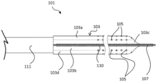
환자의 신체 내의 치료 부위로부터의 유체의 제거를 위해 치료 부위에 삽입하기 위한 디바이스. 디바이스는 유체 제거용 루멘을 적어도 부분적으로 한정하는 도관 구조체, 및 도관 구조체의 일부분을 둘러싸는 다공성 생체흡수성 외피를 포함한다. 도관 구조체는 치료의 완료 시 치료 부위로부터의 제거를 위해 구성된 제거가능한 구성요소를 포함한다.A device for insertion into a treatment area for the removal of fluid from the treatment area within the patient's body. The device includes a conduit structure at least partially defining a lumen for fluid removal, and a porous bioabsorbable sheath surrounding a portion of the conduit structure. The conduit structure includes removable components configured for removal from the treatment site upon completion of treatment.
Description
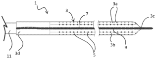
본 발명은 상처 치료 부위에 삽입하기 위한, 그 부위로의 유체의 전달을 위한, 그리고 그 부위로부터의 유체의 배출을 위한 디바이스에 관한 것이다. 특히, 디바이스는 유체 공급용 루멘 및 유체 제거용 루멘, 및 생체흡수성 외피를 갖는다.The present invention relates to a device for insertion into a wound care site, for delivery of fluid to the site, and for discharge of fluid from the site. In particular, the device has a lumen for fluid supply and a lumen for fluid removal, and a bioabsorbable shell.
외과적 또는 외상성 상처로부터의 사각(dead space)의 감소 및 유체의 배출은 종종 환자의 시기적절하고 효과적인 회복에서 중요한 인자이다. 장액종 및 혈종은 회복을 저해할 수 있는 수술 후 상처 부위에 축적된 장액 또는 혈액의 포켓이다. 적절한 배출 및 사각 폐쇄(dead space closure)의 부재 시, 불량한 치유, 감염 또는 열개(dehiscence)는 추가적인 수술 및 더 긴 병원 체류에 대한 요건을 초래할 수 있다. 장액종 및 혈종은 많은 조직 융기 및 분리를 수반하는 재건용 성형 외과 시술, 외상, 유방절제술, 종양 절제술, 제왕절개, 탈장 복원술 및 개복 외과 시술 이후에 보편적이다.Reduction of dead space and drainage of fluid from surgical or traumatic wounds are often important factors in a patient's timely and effective recovery. Seromas and hematomas are pockets of serous fluid or blood that accumulate at the site of a postoperative wound that can impede recovery. In the absence of adequate drainage and dead space closure, poor healing, infection or dehiscence may result in requirements for additional surgery and longer hospital stays. Seromas and hematomas are common after reconstructive plastic surgery procedures, trauma, mastectomies, lumpectomies, cesarean sections, hernia repairs, and open surgical procedures involving large tissue elevations and separations.
사각을 감소시키고 상처 부위로부터의 유체의 배출을 제공하는 것은 많은 경우에 매우 바람직하지만, 다른 상황에서 상처 치유 과정을 돕기 위해 상처 부위에 유체를 직접 전달할 수 있는 것이 유용하다. 예를 들어, 감염을 방지하기 위해 항균 용액을 국부적으로 점적주입(instill)한다. 유사하게, 국부 마취제의 점적주입은 통증 관리를 보조할 수 있다.Reducing deadness and providing drainage of fluid from the wound site is highly desirable in many cases, but in other situations it is useful to be able to deliver fluid directly to the wound site to aid the wound healing process. For example, an antibacterial solution is instilled locally to prevent infection. Similarly, instillation of a local anesthetic can aid in pain management.
종래 기술의 유체 제거 디바이스는 폐색되기 쉽고, 연조직 공동 내에서 장액종의 형성을 방지하는 데 효과적이지 않다. 피브리노겐 및 용해된 세포와 같은 다양한 생물학적 인자와 조합하여, 유리된(loose) 결합 조직 및 지방질 (지방) 조직과 같은 수술 후 부위에 남아 있는 유리된 조직 잔해는 이러한 디바이스가 사용 동안 실질적으로 또는 완전히 폐색되게 하는 경향이 있다. 폐색은 폐쇄된 수술 상처로부터 유체를 제거하고 치료 부위로의 진공 압력의 효과적인 전달을 제한하는 임의의 디바이스의 능력을 감소시킨다.Prior art fluid removal devices are prone to occlusion and are not effective in preventing the formation of seromas within soft tissue cavities. In combination with various biological factors such as fibrinogen and lysed cells, loose tissue debris remaining in the postoperative area, such as loose connective tissue and adipose (adipose) tissue, can cause these devices to substantially or completely occlude during use. It tends to happen. Occlusion reduces the ability of any device to remove fluid from a closed surgical wound and limits effective delivery of vacuum pressure to the treatment site.
결과적으로, 종래 기술의 유체 제거 디바이스는 대체로 낮은 레벨의 흡입(전형적으로 60 mmHg 미만의 진공)만을 적용한다. 또한, 더 높은 진공에서 이러한 디바이스를 동작시키려고 시도하는 것은 그의 유효성을 개선시키지 않고, 이는 디바이스가 폐색되는 속도를 단순히 빠르게 한다.As a result, prior art fluid removal devices typically apply only low levels of suction (vacuum typically less than 60 mmHg). Additionally, attempting to operate these devices at higher vacuums does not improve their effectiveness; it simply speeds up the rate at which the devices become occluded.
따라서, 본 발명의 목적은 전술된 단점들 중 하나 이상을 해결하는 유체 배출 또는 전달 디바이스를 제공하고/하거나 적어도 기존의 디바이스에 대한 유용한 대안을 제공하는 것이다.Accordingly, it is an object of the present invention to provide a fluid discharge or delivery device that solves one or more of the above-described disadvantages and/or at least provides a useful alternative to existing devices.
특허 명세서, 기타 외부 문서, 또는 기타 정보 자료를 참조한 본 명세서에서, 이는 일반적으로 본 발명의 특징을 논의하기 위한 배경을 제공하기 위한 것이다. 달리 구체적으로 언급하지 않는 한, 그러한 외부 문서 또는 정보 자료에 대한 언급은 그 어떤 재판관할에서도 그러한 문서 또는 정보 자료가 선행 기술이라거나 또는 해당 기술 분야의 보편적인 일반 지식의 일부를 형성하는 것이라고 인정하는 것으로 해석되어서는 안 된다.Where reference is made herein to patent specifications, other external documents, or other information sources, it is generally intended to provide a background for discussing the features of the invention. Unless specifically stated otherwise, any reference to such external document or information material does not constitute a finding in any jurisdiction that such document or information material is prior art or forms part of the general general knowledge in the art. It should not be interpreted as
제1 태양에서, 본 발명은 환자의 신체 내의 치료 부위로부터의 유체의 제거를 위해 치료 부위에 삽입하기 위한 디바이스를 제공한다. 디바이스는 유체 제거용 루멘을 적어도 부분적으로 한정하는 도관 구조체, 및 도관 구조체의 일부분을 둘러싸는 다공성 생체흡수성 외피를 포함한다. 도관 구조체는 치료의 완료 시 치료 부위로부터의 제거를 위해 구성된 제거가능한 구성요소를 포함한다. In a first aspect, the invention provides a device for insertion into a treatment site for removal of fluid from the treatment site within a patient's body. The device includes a conduit structure at least partially defining a lumen for fluid removal, and a porous bioabsorbable sheath surrounding a portion of the conduit structure. The conduit structure includes removable components configured for removal from the treatment site upon completion of treatment.
일 실시 형태에서, 디바이스는 유체를 치료 부위로 전달하도록 구성되고, 도관 구조체는 유체 공급용 루멘을 추가로 한정한다. 유체 공급용 루멘의 일 단부는 유체 제거용 루멘의 일 단부와 유체 연통할 수 있다.In one embodiment, the device is configured to deliver fluid to a treatment site, and the conduit structure further defines a lumen for fluid supply. One end of the lumen for fluid supply may be in fluid communication with one end of the lumen for fluid removal.
일 실시 형태에서, 디바이스는 하나 이상의 외부 구성요소와 연결하기 위한 이중 루멘 포트를 포함하고, 포트의 제1 루멘은 유체 제거용 루멘과 유체 연통한다.In one embodiment, the device includes a dual lumen port for connection to one or more external components, wherein a first lumen of the port is in fluid communication with the lumen for fluid removal.
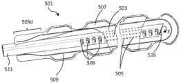
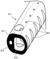
일 실시 형태에서, 생체흡수성 외피는 치료 부위와 도관 구조체 사이의 유체 연통을 가능하게 하도록 위치된 복수의 개구부를 포함하고, 개구부 각각은 면적이 약 1 ㎟ 이하이다. 예를 들어, 외피 내의 개구부 각각은 면적이 약 0.2 ㎟ 내지 약 0.8 ㎟일 수 있다.In one embodiment, the bioabsorbable sheath includes a plurality of openings positioned to enable fluid communication between the treatment site and the conduit structure, each opening having an area of about 1 mm2 or less. For example, each opening within the shell may have an area of about 0.2 mm2 to about 0.8 mm2.
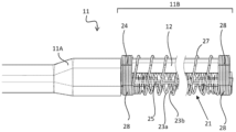
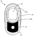
일 실시 형태에서, 외피는 도관 구조체의 상단 부분 위를 감싸는 상단 시트, 및 도관 구조체의 하단 부분 위를 감싸는 하단 시트를 포함하고, 상단 및 하단 시트들은 측부 시임을 따라 도관 구조체 주위에서 연결된다. 상단 및 하단 시트들은 함께 스티칭될(stitched) 수 있다.In one embodiment, the sheath includes a top sheet wrapped over a top portion of the conduit structure, and a bottom sheet wrapped over a bottom portion of the conduit structure, with the top and bottom sheets connected around the conduit structure along side seams. The top and bottom sheets may be stitched together.
일 실시 형태에서, 외피는, 치료 부위에서 조직에 디바이스를 고정하기 위해, 측부 시임을 넘어서 연장되는 하나 이상의 플랜지(들) 또는 탭(들)을 형성한다. 플랜지 또는 탭은 2개의 층을 포함할 수 있고, 층은 플랜지 또는 탭의 에지에서 또는 그 근처에서 부착된다.In one embodiment, the sheath forms one or more flange(s) or tab(s) extending beyond the side seams to secure the device to tissue at the treatment site. The flange or tab may include two layers, with the layers attached at or near the edge of the flange or tab.
일 실시 형태에서, 외피 내의 개구부는 디바이스의 상부 및 하부 표면들 상에 제공된다.In one embodiment, openings in the shell are provided on the top and bottom surfaces of the device.
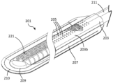
일 실시 형태에서, 외피는 도관 구조체 내로의 상처 잔해의 침입을 방지하거나 최소화하도록 구성된, 디바이스의 입구 및 출구의 근위에 있는 단부 섹션을 포함한다. 외피의 단부 섹션은 바람직하게는 관통 개구부를 포함하지 않는다.In one embodiment, the sheath includes end sections proximal to the inlet and outlet of the device, configured to prevent or minimize ingress of wound debris into the conduit structure. The end sections of the shell preferably do not include through openings.
일 실시 형태에서, 디바이스의 입구 및 출구의 원위에 있는 외피의 단부는 폐쇄된다. 대안적으로, 디바이스의 입구 및 출구의 원위에 있는 외피의 단부는 개방될 수 있다.In one embodiment, the ends of the sheath distal to the inlet and outlet of the device are closed. Alternatively, the ends of the sheath distal to the inlet and outlet of the device may be open.
일 실시 형태에서, 외피는 세포외 기질(extracellular matrix, ECM) 또는 중합체 재료의 하나 이상의 층을 포함한다. ECM은 반추동물 전위의 탈세포화된 고유-점막하층(propria-submucosa)으로부터 형성될 수 있다.In one embodiment, the envelope includes one or more layers of extracellular matrix (ECM) or polymeric material. ECM can be formed from the decellularized propria-submucosa of the ruminant anterior chamber.
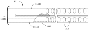
일 실시 형태에서, 제거가능한 도관 구조체의 유체 공급용 루멘은 구조체의 길이의 적어도 주요 부분을 따라 비-다공성 벽을 포함한다.In one embodiment, the fluid supply lumen of the removable conduit structure includes a non-porous wall along at least a major portion of the length of the structure.
제거가능한 도관 구조체의 유체 제거용 루멘은 구조체의 길이의 주요 부분을 따라 다공성 벽을 포함할 수 있다.The fluid removal lumen of the removable conduit structure may include a porous wall along a major portion of the length of the structure.
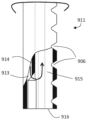
일 실시 형태에서, 제거가능한 도관 구조체의 유체 제거용 루멘의 적어도 주요 일부분을 한정하는 트러스(truss)를 포함한다. 일 실시 형태에서, 트러스는 복수의 교차 노드에서 주기적으로 서로 교차하도록 권취된 2개의 가요성 세장형 벽 부재를 포함한다. 각각의 세장형 벽 부재는 대체로 나선형일 수 있고, 2개의 벽 부재는 반대로 권취된다. 트러스는 둥근 또는 난형 단면을 갖는 가요성 튜브를 형성한다.In one embodiment, it includes a truss defining at least a major portion of the fluid removal lumen of the removable conduit structure. In one embodiment, the truss includes two flexible elongated wall members wound to periodically intersect each other at a plurality of intersection nodes. Each elongated wall member may be generally helical, with the two wall members being wound in opposite directions. A truss forms a flexible tube with a round or oval cross-section.
일부 실시 형태에서, 트러스는 적어도 2개의 가요성 세장형 브레이싱 부재를 포함할 수 있고, 각각의 브레이싱 부재는 복수의 교차 노드에서 2개의 세장형 벽 부재에 연결된다. 브레이싱 부재는 채널의 일 측부를 따라 대체로 종방향으로 연장될 수 있다. 브레이싱 트러스 부재는 채널의 서로 반대편인 측부들 상에 제공될 수 있다. 각각의 브레이싱 부재는 각자의 교차 노드에서 2개의 세장형 벽 부재에 접합될 수 있다.In some embodiments, the truss can include at least two flexible elongated bracing members, each bracing member connected to two elongated wall members at a plurality of intersection nodes. The bracing member may extend generally longitudinally along one side of the channel. Bracing truss members may be provided on opposite sides of the channel. Each bracing member may be joined to two elongated wall members at their respective intersection nodes.
일 실시 형태에서, 트러스는 유체 제거용 루멘의 트러스를 유체 공급용 루멘에 고정하도록 권취된 고정 트러스 부재를 포함할 수 있다.In one embodiment, the truss may include wound anchoring truss members to secure the truss of the fluid removal lumen to the fluid supply lumen.
일 실시 형태에서, 제거가능한 도관 구조체는 실리콘 형태를 포함한다.In one embodiment, the removable conduit structure comprises a silicone form.
일 실시 형태에서, 유체 제거용 루멘은 단면적이 적어도 7 ㎟, 예를 들어, 단면적이 약 18 ㎟이다.In one embodiment, the lumen for fluid removal has a cross-sectional area of at least 7 mm2, for example, about 18 mm2.
일 실시 형태에서, 유체 제거용 루멘은 입구 단부 및 출구 단부를 갖고, 유체 공급용 루멘은 유체 제거용 루멘의 입구 단부에 인접하게 유체를 공급하도록 구성된다.In one embodiment, the fluid removal lumen has an inlet end and an outlet end, and the fluid supply lumen is configured to supply fluid adjacent the inlet end of the fluid removal lumen.
일 실시 형태에서, 유체 공급용 루멘 및 유체 제거용 루멘은 길이가 대체로 동일하고 서로 인접하게 위치된다.In one embodiment, the lumen for fluid supply and the lumen for fluid removal are approximately equal in length and located adjacent to each other.
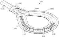
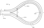
일 실시 형태에서, 유체 공급용 루멘 및 유체 제거용 루멘은 동일 선상에 있다. 예를 들어, 디바이스는 루프를 형성할 수 있다. 일 실시 형태에서, 루프는 맞닿은 단부들을 갖는 도관 구조체의 2개의 돌출부를 포함한다.In one embodiment, the lumen for fluid supply and the lumen for fluid removal are collinear. For example, a device can form a loop. In one embodiment, the loop includes two protrusions of a conduit structure with abutting ends.
일 실시 형태에서, 디바이스는 유체 제거용 및/또는 유체 공급용 루멘과 유체 연통하고 음압원 또는 양압원에 연결가능한 포트를 포함한다.In one embodiment, the device includes a port in fluid communication with the lumen for fluid removal and/or fluid supply and connectable to a negative or positive pressure source.
치료 부위는 수술 동안 또는 외상의 결과로서 분리되었던 근육 조직, 결합 조직 및/또는 피부 조직의 표면들 또는 평면들 사이의 영역, 또는 조직의 층 내의 영역일 수 있다.The treatment area may be an area between surfaces or planes of muscle tissue, connective tissue and/or skin tissue, or an area within a layer of tissue that has been separated during surgery or as a result of trauma.
일 실시 형태에서, 외피는, 도관 구조체의 아래에 놓인 부분과 억지 끼워맞춤을 갖고 개구부가 없는 밀봉 단부 섹션을 포함한다. 외피의 밀봉 단부 섹션은 유체 불침투성 벽을 포함하는 도관 구조체의 일부분 위에 연장된다.In one embodiment, the sheath includes a sealed end section that has an interference fit with the underlying portion of the conduit structure and has no openings. The sealing end section of the sheath extends over a portion of the conduit structure that includes the fluid impermeable wall.
일 실시 형태에서, 외피 및 아래에 놓인 도관 구조체의 단면적은 밀봉 섹션의 적어도 일부분을 따라 감소된다.In one embodiment, the cross-sectional area of the sheath and underlying conduit structure is reduced along at least a portion of the sealing section.
일 실시 형태에서, 외피 및 아래에 놓인 도관 구조체의 단면적은 밀봉 섹션의 적어도 일부분을 따라 테이퍼링된다.In one embodiment, the cross-sectional area of the sheath and underlying conduit structure is tapered along at least a portion of the sealing section.
제2 태양에서, 본 발명은 환자의 신체 내의 치료 부위로의 유체의 전달 및/또는 그로부터의 유체의 제거를 위해 치료 부위에 삽입하기 위한 디바이스를 제공한다. 디바이스는 유체 공급용 및/또는 제거용 루멘을 한정하는 도관 구조체 및 제거가능한 도관 구조체의 일부분을 둘러싸는 생체흡수성 외피를 포함한다. 외피는 디바이스 내의 폐색을 방지하면서 치료 부위와 도관 구조체 사이의 유체 연통을 가능하게 하도록 크기설정되고 위치된 복수의 개구부를 포함한다. In a second aspect, the invention provides a device for insertion into a treatment site for delivery of fluid to and/or removal of fluid from the treatment site within a patient's body. The device includes a conduit structure defining a lumen for fluid delivery and/or removal and a bioabsorbable sheath surrounding a portion of the removable conduit structure. The sheath includes a plurality of openings sized and positioned to enable fluid communication between the treatment site and the conduit structure while preventing occlusion within the device.
일 실시 형태에서, 외피 내의 개구부 각각은 면적이 약 0.2 ㎟ 내지 약 0.8 ㎟이다.In one embodiment, each opening in the shell is between about 0.2 mm2 and about 0.8 mm2 in area.
일 실시 형태에서, 외피는, 도관 구조체의 아래에 놓인 부분과 억지 끼워맞춤을 갖고 개구부가 없는 밀봉 단부 섹션을 포함한다.In one embodiment, the sheath includes a sealed end section that has an interference fit with the underlying portion of the conduit structure and has no openings.
일 실시 형태에서, 외피의 밀봉 단부 섹션은 유체 불침투성 벽을 포함하는 도관 구조체의 일부분 위에 연장된다.In one embodiment, the sealing end section of the sheath extends over a portion of the conduit structure that includes the fluid impermeable wall.
일 실시 형태에서, 외피 및 아래에 놓인 도관 구조체의 단면적은 밀봉 섹션의 적어도 일부분을 따라 감소된다.In one embodiment, the cross-sectional area of the sheath and underlying conduit structure is reduced along at least a portion of the sealing section.
일 실시 형태에서, 외피 및 아래에 놓인 도관 구조체의 단면적은 밀봉 섹션의 적어도 일부분을 따라 테이퍼링된다.In one embodiment, the cross-sectional area of the sheath and underlying conduit structure is tapered along at least a portion of the sealing section.
일 실시 형태에서, 디바이스는 도관 구조체의 루멘(들)과 유체 연통하는 포트를 포함한다.In one embodiment, the device includes a port in fluid communication with the lumen(s) of the conduit structure.
일 실시 형태에서, 도관 구조체는 치료의 완료 시 치료 부위로부터의 제거를 위해 구성된 제거가능한 구성요소를 포함한다.In one embodiment, the conduit structure includes a removable component configured for removal from the treatment site upon completion of treatment.
제2 태양에 따른 디바이스는 제1 태양과 관련하여 전술된 특징부들 중 임의의 하나 이상을 포함할 수 있다.A device according to the second aspect may include any one or more of the features described above with respect to the first aspect.
제3 태양에서, 본 발명은 환자의 신체 내의 치료 부위로의 유체의 전달 및/또는 그로부터의 유체의 제거를 위해 치료 부위에 삽입하기 위한 디바이스를 제공하는데, 디바이스는, In a third aspect, the invention provides a device for insertion into a treatment site for delivery of fluid to and/or removal of fluid from a treatment site within a patient's body, the device comprising:
유체 공급용 루멘 및 다공성 유체 제거용 루멘을 한정하는 도관 구조체 - 유체 공급용 루멘의 일 단부는 유체 제거용 루멘의 제1 단부와 유체 연통함 -;a conduit structure defining a fluid supply lumen and a porous fluid removal lumen, wherein one end of the fluid supply lumen is in fluid communication with a first end of the fluid removal lumen;
제거가능한 도관 구조체의 일부분을 둘러싸는 생체흡수성 외피; 및a bioabsorbable sheath surrounding a portion of the removable conduit structure; and
유체 공급용 루멘 및/또는 유체 제거용 루멘(들)과 유체 연통하는 포트를 포함한다.and a port in fluid communication with the lumen(s) for fluid supply and/or lumen(s) for fluid removal.
일 실시 형태에서, 디바이스는 이중 루멘 포트를 포함하고, 포트의 제1 루멘은 유체 공급용 루멘과 유체 연통하고 포트의 제2 루멘은 유체 제거용 루멘과 유체 연통한다.In one embodiment, the device includes a dual lumen port, where a first lumen of the port is in fluid communication with a lumen for fluid supply and a second lumen of the port is in fluid communication with a lumen for fluid removal.
유체 공급용 루멘을 한정하는 도관 구조체의 일부분은 유체 제거용 루멘을 한정하는 도관 구조체의 일부분과 일체로 형성될 수 있다.The portion of the conduit structure defining the lumen for fluid supply may be formed integrally with the portion of the conduit structure defining the lumen for fluid removal.
일 실시 형태에서, 유체 공급용 루멘 및 유체 제거용 루멘은 동축이다. 대안적으로, 유체 공급용 루멘 및 유체 제거용 루멘은 실질적으로 평행할 수 있다.In one embodiment, the lumen for fluid supply and the lumen for fluid removal are coaxial. Alternatively, the lumen for fluid supply and the lumen for fluid removal may be substantially parallel.
일 실시 형태에서, 포트는 하나 이상의 외부 구성요소와의 연결을 위해 구성된다.In one embodiment, the port is configured for connection to one or more external components.
일 실시 형태에서, 외피는 외피를 가로지르는 유체 전달을 용이하게 하기 위한 다수의 개구부를 포함하고, 각각의 개구부는 면적이 약 0.2 ㎟ 내지 약 0.8 ㎟이다.In one embodiment, the shell includes a plurality of openings to facilitate fluid transfer across the shell, each opening being about 0.2 mm2 to about 0.8 mm2 in area.
일 실시 형태에서, 외피는, 도관 구조체의 아래에 놓인 부분과 억지 끼워맞춤을 갖고 개구부가 없는 밀봉 단부 섹션을 포함한다.In one embodiment, the sheath includes a sealed end section that has an interference fit with the underlying portion of the conduit structure and has no openings.
일 실시 형태에서, 도관 구조체는 치료의 완료 시 치료 부위로부터의 제거를 위해 구성된 제거가능한 구성요소를 포함한다.In one embodiment, the conduit structure includes a removable component configured for removal from the treatment site upon completion of treatment.
제3 태양에 따른 디바이스는 제1 또는 제2 태양과 관련하여 전술된 특징부들 중 임의의 하나 이상을 포함할 수 있다.A device according to the third aspect may include any one or more of the features described above with respect to the first or second aspect.
제4 태양에서, 본 발명은 치료 부위로부터 유체를 배출하고 유체를 환자의 신체 내의 치료 부위로 전달하기 위한 시스템을 제공하는데, 시스템은, In a fourth aspect, the present invention provides a system for draining fluid from a treatment site and delivering fluid to a treatment site within a patient's body, the system comprising:
(i) 제1, 제2 또는 제3 태양에 따른 디바이스;(i) A device according to the first, second or third aspect;
(ii) 디바이스의 포트에 또는 유체 불침투성 드레싱에 해제가능하게 결합되는 도관;(ii) a conduit releasably coupled to a port of the device or to a fluid impermeable dressing;
(iii) 환자의 신체의 외부에 위치되고 치료 유체를 포함하며, 유체 공급용 루멘과 유체 연통하는 저장소(reservoir);(iii) a reservoir located outside the patient's body, containing therapeutic fluid, and in fluid communication with a lumen for fluid supply;
(iv) 환자의 신체의 외부에 위치되고, 디바이스로부터 유체를 수용하기 위해 유체 제거용 루멘과 유체 연통하는 제2 저장소; 및(iv) a second reservoir located external to the patient's body and in fluid communication with the fluid removal lumen to receive fluid from the device; and
(v) 도관에 결합되어 양압 또는 음압을 디바이스로 전달하기 위한 압력원을 포함한다.(v) It is coupled to the conduit and includes a pressure source for delivering positive or negative pressure to the device.
일 실시 형태에서, 압력원은 디바이스에 음압을 전달할 수 있어서, 유체가 치료 부위로부터 디바이스 내로 배출되고 도관을 통해 저장소로 이송되도록 한다.In one embodiment, the pressure source can deliver negative pressure to the device, causing fluid to be expelled from the treatment site into the device and through the conduit to the reservoir.
일 실시 형태에서, 디바이스의 포트는 환자의 신체의 외부에 위치된다.In one embodiment, the port of the device is located external to the patient's body.
제5 태양에서, 본 발명은 제1, 제2 또는 제3 태양에 따른 디바이스로서의 디바이스를 형성하기 위한 부품들의 키트를 제공하는데, 부품들의 키트는 유체 제거용 루멘을 한정하는 도관 구조체, 및 도관 구조체의 수용을 위한 통로를 한정하는 생체흡수성 외피를 포함한다. In a fifth aspect, the invention provides a kit of parts for forming a device as a device according to the first, second or third aspect, the kit of parts comprising a conduit structure defining a lumen for fluid removal, and the conduit structure It includes a bioabsorbable shell that defines a passageway for the reception of .
일 실시 형태에서, 생체흡수성 외피는 대체로, 2개의 개방 단부를 갖는 튜브형이다.In one embodiment, the bioabsorbable shell is generally tubular with two open ends.
제6 태양에서, 본 발명은 상처를 치료하기 위한 시스템을 제공하며, 시스템은 상처에 위치된 상처 치료 디바이스로의 연결을 위한 유체 입력부 및 유체 출력부를 포함한다. 상처 치료 디바이스는 전술된 바와 같을 수 있다. 유체 입력부는 상처 치료 디바이스의 상류 측에 유체적으로 연결되도록 적응되고, 유체 출력부는 상처 치료 디바이스의 하류 측에 유체적으로 연결되도록 적응된다. 시스템은 유체 출력부의 상류의 공기 입구 밸브; 공기 입구 밸브를 개방 위치와 폐쇄 위치 사이에서 구동하기 위한 액추에이터; 유체 입력부의 하류의 펌프; 상처 치료 디바이스에 음압을 제공하도록 펌프를 구동하기 위한 모터; 및 공기 입구 밸브 및 펌프를 작동시키기 위해 액추에이터 및 모터와 통신하는 제어기를 추가로 포함한다. 제어기는, i) 공기 입구 밸브를 개방하고 펌프를 동작시켜 상처 치료 디바이스에서 제1 진공 압력을 유지하고 공기를 상처 치료 디바이스 내로 도입하도록; 그리고 ii) 공기 입구 밸브를 폐쇄하고 펌프를 동작시켜 상처 치료 디바이스에서 제2 진공 압력을 유지하고 공기 및 유체를 상처 치료 디바이스로부터 제거하도록 구성된다. 제1 진공 압력은 제2 진공 압력 이하이다.In a sixth aspect, the present invention provides a system for treating a wound, the system comprising a fluid input and a fluid output for connection to a wound care device located at the wound. The wound care device may be as described above. The fluid input is adapted to be fluidly connected to an upstream side of the wound care device, and the fluid output is adapted to be fluidly connected to a downstream side of the wound care device. The system includes an air inlet valve upstream of the fluid output; an actuator for driving the air inlet valve between open and closed positions; a pump downstream of the fluid input; a motor to drive the pump to provide negative pressure to the wound care device; and a controller in communication with the actuator and motor to operate the air inlet valve and pump. The controller may: i) open the air inlet valve and operate the pump to maintain a first vacuum pressure in the wound care device and introduce air into the wound care device; and ii) closing the air inlet valve and operating the pump to maintain a second vacuum pressure in the wound care device and remove air and fluid from the wound care device. The first vacuum pressure is less than or equal to the second vacuum pressure.
일 실시 형태에서, 제어기는 공기 밸브가 개방되고 폐쇄될 때 상처 치료 디바이스에서 음압 환경을 연속적으로 유지하기 위해 펌프를 동작시키도록 구성된다.In one embodiment, the controller is configured to operate the pump to continuously maintain a negative pressure environment in the wound care device as the air valve opens and closes.
일 실시 형태에서, 제1 및 제2 진공 압력은 효과적인 음압 상처 치료법(negative pressure wound therapy)을 제공한다.In one embodiment, the first and second vacuum pressures provide effective negative pressure wound therapy.
일 실시 형태에서, 제어기는 단계 i) 및 단계 ii)를 반복하여 공기 입구 밸브를 개방 위치와 폐쇄 위치 사이에서 사이클링하도록 구성된다.In one embodiment, the controller is configured to cycle the air inlet valve between open and closed positions by repeating steps i) and step ii).
일 실시 형태에서, 제어기는 단계 i) 및 단계 ii)를 반복하여 공기 입구 밸브를 개방 위치와 폐쇄 위치 사이에서 연속적으로 사이클링하도록 구성된다.In one embodiment, the controller is configured to continuously cycle the air inlet valve between open and closed positions by repeating steps i) and step ii).
일 실시 형태에서, 제어기는 공기 입구 밸브가 개방될 때 실질적으로 일정한 제1 진공 압력을 유지하기 위해 펌프를 동작시키도록 구성된다.In one embodiment, the controller is configured to operate the pump to maintain the first vacuum pressure substantially constant when the air inlet valve is opened.
일 실시 형태에서, 제어기는 공기 입구 밸브가 개방된 상태에서, 공기 입구 밸브를 통한 시스템 내로의 공기의 유량이 펌프의 유량과 동일하도록 하기 위해 펌프를 동작시키도록 구성된다.In one embodiment, the controller is configured to operate the pump, with the air inlet valve open, such that the flow rate of air into the system through the air inlet valve is equal to the flow rate of the pump.
일 실시 형태에서, 제어기는 공기 입구 밸브가 폐쇄될 때 실질적으로 일정한 제2 진공 압력을 유지하기 위해 펌프를 동작시키도록 구성된다.In one embodiment, the controller is configured to operate the pump to maintain the second vacuum pressure substantially constant when the air inlet valve is closed.
일 실시 형태에서, 제어기는, 단계 (i)에서, 시스템이 치료 디바이스에 걸쳐 0 또는 일정한 압력 차이를 갖는 평형 상태에 있도록 하기 위해, 공기 입구 밸브가 개방된 상태에서, 펌프를 동작시키도록 구성된다.In one embodiment, the controller is configured to, in step (i), operate the pump with the air inlet valve open such that the system is in equilibrium with a zero or constant pressure difference across the treatment device. .
일 실시 형태에서, 제어기는, 단계 (ii)에서, 시스템이 치료 디바이스에 걸쳐 0 또는 일정한 압력 차이를 갖는 평형 상태에 있도록 하기 위해, 공기 입구 밸브가 폐쇄된 상태에서, 펌프를 동작시키도록 구성된다.In one embodiment, the controller is configured to, in step (ii), operate the pump with the air inlet valve closed such that the system is in equilibrium with a zero or constant pressure difference across the treatment device. .
일 실시 형태에서, 제어기는 상처 치료 디바이스로부터 유체 유동에 혼입된 공기의 버블 또는 슬러그를 포함하는 버블 유동 또는 슬러그 유동을 생성하는 공기의 유량을 시스템 내로 도입하기 위해 공기 입구 밸브를 개방된 상태와 폐쇄된 상태 사이에서 동작시키도록 구성된다.In one embodiment, the controller opens and closes an air inlet valve to introduce a flow rate of air into the system that creates a bubble flow or slug flow comprising bubbles or slugs of air entrained in the fluid flow from the wound care device. It is configured to operate between the specified states.
일 실시 형태에서, 제어기는 상처에서 유체의 밀도를 감소시켜 중력에 대항하여 상처로부터 유체를 들어올리기 위해 공기 입구 밸브를 개방된 상태와 폐쇄된 상태 사이에서 동작시키도록 구성된다.In one embodiment, the controller is configured to operate the air inlet valve between an open and closed state to lift fluid from the wound against gravity by reducing the density of fluid in the wound.
일 실시 형태에서, 제어기는 공기 입구 밸브를 주기적으로 개방하고 폐쇄하도록 구성된다.In one embodiment, the controller is configured to periodically open and close the air inlet valve.
일 실시 형태에서, 단계 i)에서, 제어기는 미리결정된 기간 동안 공기 입구 밸브를 개방하도록 구성된다. 일 실시 형태에서, 단계 i)에서, 제어기는 적어도 10초 동안 공기 입구 밸브를 개방하도록 구성된다.In one embodiment, in step i), the controller is configured to open the air inlet valve for a predetermined period of time. In one embodiment, in step i), the controller is configured to open the air inlet valve for at least 10 seconds.
일 실시 형태에서, 단계 ii)에서, 제어기는 미리결정된 기간 동안 공기 입구 밸브를 폐쇄하도록 구성된다.In one embodiment, in step ii), the controller is configured to close the air inlet valve for a predetermined period of time.
일 실시 형태에서, 공기 입구 밸브는 사이클 피치의 적어도 10%, 또는 사이클 피치의 적어도 20%, 또는 사이클 피치의 적어도 30%, 또는 사이클 피치의 40%, 또는 사이클 피치의 적어도 50% 동안 개방된다.In one embodiment, the air inlet valve is open for at least 10% of the cycle pitch, or at least 20% of the cycle pitch, or at least 30% of the cycle pitch, or 40% of the cycle pitch, or at least 50% of the cycle pitch.
일 실시 형태에서, 단계 i)에서, 공기 입구 밸브는 시스템을 통해 전달되는 공기의 부피가 시스템의 총 부피의 적어도 상당한 부분이 되도록 충분한 기간 동안 개방된다. 예를 들어, 단계 i)에서, 공기 입구 밸브는 시스템으로 전달되는 공기의 부피가 시스템의 총 부피의 적어도 50% 또는 적어도 100%가 되도록 충분한 기간 동안 개방될 수 있다.In one embodiment, in step i), the air inlet valve is opened for a sufficient period of time such that the volume of air delivered through the system is at least a significant portion of the total volume of the system. For example, in step i), the air inlet valve may be opened for a sufficient period of time such that the volume of air delivered to the system is at least 50% or at least 100% of the total volume of the system.
일 실시 형태에서, 제1 진공 압력은 제2 진공 압력의 약 30% 내지 100%이다.In one embodiment, the first vacuum pressure is about 30% to 100% of the second vacuum pressure.
일 실시 형태에서, 제1 진공 압력은 약 50 내지 100 mmHg, 바람직하게는 약 80 내지 약 90 mmHg이다.In one embodiment, the first vacuum pressure is about 50 to 100 mmHg, preferably about 80 to about 90 mmHg.
일 실시 형태에서, 제2 진공 압력은 약 100 내지 150 mmHg, 바람직하게는 약 100 내지 약 110 mmHg이다.In one embodiment, the second vacuum pressure is about 100 to 150 mmHg, preferably about 100 to about 110 mmHg.
일 실시 형태에서, 제1 진공 압력은 제2 압력보다 약 10 내지 50 mmHg 작다.In one embodiment, the first vacuum pressure is about 10 to 50 mmHg less than the second pressure.
일 실시 형태에서, 단계 (i)에서, 제어기는 진공 압력 임계치를 달성하기 위해 펌프를 동작시키도록 구성된다. 일 실시 형태에서, 단계 (ii)에서, 제어기는 진공 압력 임계치를 달성하기 위해 펌프를 동작시키도록 구성된다.In one embodiment, in step (i), the controller is configured to operate the pump to achieve the vacuum pressure threshold. In one embodiment, in step (ii), the controller is configured to operate the pump to achieve the vacuum pressure threshold.
일 실시 형태에서, 시스템은, 상처 치료 디바이스의 하류에 위치되고 제어기와 통신하는 하류 압력 센서를 포함한다. 제어기는, 단계 i)에서, 하류 압력 센서에 의해 감지된 압력에 기초하여 진공 압력 임계치를 달성하기 위해 펌프를 동작시키도록 구성될 수 있다.In one embodiment, the system includes a downstream pressure sensor located downstream of the wound care device and in communication with a controller. The controller may be configured, in step i), to operate the pump to achieve a vacuum pressure threshold based on the pressure sensed by the downstream pressure sensor.
일 실시 형태에서, 시스템은, 상처 치료 디바이스의 상류에 위치되고 제어기와 통신하는 상류 압력 센서를 포함한다. 제어기는, 단계 ii)에서, 상류 압력 센서에 의해 감지된 압력에 기초하여 진공 압력 임계치를 달성하기 위해 펌프를 동작시키도록 구성될 수 있다.In one embodiment, the system includes an upstream pressure sensor located upstream of the wound care device and in communication with a controller. The controller may be configured, in step ii), to operate the pump to achieve a vacuum pressure threshold based on the pressure sensed by the upstream pressure sensor.
일 실시 형태에서, 시스템은,In one embodiment, the system:
상처 치료 디바이스의 상류에 위치되고 제어기와 통신하는 상류 압력 센서, 및an upstream pressure sensor located upstream of the wound care device and in communication with a controller, and
상처 치료 디바이스의 하류에 위치되고 제어기와 통신하는 하류 압력 센서를 포함하고,a downstream pressure sensor positioned downstream of the wound care device and in communication with a controller;
제어기는, 단계 i)에서, 하류 압력 센서에 의해 감지된 압력에 기초하여 제1 진공 압력 임계치를 달성하기 위해 펌프를 동작시키도록; 그리고The controller, in step i), operates the pump to achieve a first vacuum pressure threshold based on the pressure sensed by the downstream pressure sensor; and
단계 ii)에서, 상류 압력 센서에 의해 감지된 압력에 기초하여 제2 진공 압력 임계치를 달성하기 위해 펌프를 동작시키도록 구성된다.In step ii), the pump is configured to operate to achieve a second vacuum pressure threshold based on the pressure sensed by the upstream pressure sensor.
일 실시 형태에서, 제1 진공 압력 임계치는 제2 진공 압력 임계치 이하이다.In one embodiment, the first vacuum pressure threshold is less than or equal to the second vacuum pressure threshold.
일 실시 형태에서, 시스템은 입구 제한부를 포함하고, 상류 압력 센서는 공기 입구 밸브가 개방될 때 상류 압력 센서가 주변 압력을 측정하도록 입구 제한부의 상류에 위치된다.In one embodiment, the system includes an inlet restrictor, and an upstream pressure sensor is positioned upstream of the inlet restrictor such that the upstream pressure sensor measures ambient pressure when the air inlet valve is opened.
일 실시 형태에서, 시스템은 주변 압력과 상처 치료 디바이스에서의 진공 압력 사이에 미리결정된 압력 강하를 제시하기 위한 입구 제한부를 포함한다.In one embodiment, the system includes an inlet restrictor for presenting a predetermined pressure drop between ambient pressure and vacuum pressure at the wound care device.
일 실시 형태에서, 시스템은 시스템에 도입된 공기를 필터링하기 위한 필터를 포함하고, 필터는 입구 제한부이거나 이를 포함한다.In one embodiment, the system includes a filter for filtering air introduced into the system, the filter being or comprising an inlet restrictor.
일 실시 형태에서, 압력 강하는 대략 20 내지 130 mmHg이다.In one embodiment, the pressure drop is approximately 20 to 130 mmHg.
일 실시 형태에서, 공기 입구 밸브가 개방될 때, 주변 압력과 상처 치료 디바이스의 하류의 압력 사이의 실질적으로 모든 압력 차이는 입구 제한부에서의 것이다.In one embodiment, when the air inlet valve is open, substantially all of the pressure difference between the ambient pressure and the pressure downstream of the wound care device is at the inlet restrictor.
일 실시 형태에서, 시스템은 상처로부터 제거된 유체를 수집하기 위한 저장소를 포함하고, 저장소는 펌프의 하류에 위치되어, 상처로부터 제거된 유체가 펌프를 통해 저장소로 전달되도록 한다.In one embodiment, the system includes a reservoir for collecting fluid removed from the wound, and the reservoir is located downstream of a pump, such that fluid removed from the wound is delivered to the reservoir via the pump.
일 실시 형태에서, 저장소는 가요성 백을 포함한다.In one embodiment, the reservoir includes a flexible bag.
일 실시 형태에서, 저장소는 저장소를 주변 분위기로 통기하기 위한 통기구를 포함한다.In one embodiment, the reservoir includes a vent for venting the reservoir to the surrounding atmosphere.
일 실시 형태에서, 시스템은 치료 유체의 공급부를 연결하기 위해 유체 출구의 상류에 치료 유체 입구를 포함한다.In one embodiment, the system includes a treatment fluid inlet upstream of the fluid outlet to connect a supply of treatment fluid.
일 실시 형태에서, 시스템은, 단계 i)에서, 제1 진공 압력에 의해 상처 치료 디바이스로 공기를 도입함으로써 상처 치료 디바이스로의 치료 유체의 도입이 방지되거나 감소되고, 단계 ii)에서, 치료 유체가 제2 진공 압력에 의해 상처 치료 디바이스로 끌어당겨지도록 구성된다.In one embodiment, the system is configured to prevent or reduce the introduction of treatment fluid into the wound treatment device by introducing air into the wound treatment device by means of a first vacuum pressure, in step i), and wherein in step ii), the treatment fluid is It is configured to be pulled into the wound treatment device by a second vacuum pressure.
일 실시 형태에서, 시스템은,In one embodiment, the system:
치료 유체 입구와 유체 출구 사이의 치료 유체 밸브, 및a treatment fluid valve between a treatment fluid inlet and a fluid outlet, and
공기 입구 밸브를 개방 위치와 폐쇄 위치 사이에서 구동하기 위한 액추에이터를 포함하고, 제어기는 유체 입구 밸브 액추에이터와 통신하고, 제어기는 유체 공급 상태에서,an actuator for actuating the air inlet valve between an open position and a closed position, wherein the controller is in communication with the fluid inlet valve actuator, wherein in the fluid supply state, the controller:
iii) 유체 입구 밸브를 개방하고 펌프를 동작시켜 상처 치료 디바이스에서 진공 압력을 유지하고 치료 유체를 상처 치료 디바이스 내로 도입하도록; 그리고iii) open the fluid inlet valve and operate the pump to maintain vacuum pressure in the wound treatment device and introduce treatment fluid into the wound treatment device; and
iv) 유체 입구 밸브를 폐쇄하고 펌프를 동작시켜 상처 치료 디바이스에서 진공 압력을 유지하고 상처 치료 디바이스로부터 유체를 제거하도록 구성된다.iv) Close the fluid inlet valve and operate the pump to maintain vacuum pressure in the wound care device and remove fluid from the wound care device.
일 실시 형태에서, 제어기는 유체 입구 밸브가 개방되고 폐쇄될 때 상처 치료 디바이스에서 음압 환경을 연속적으로 유지하기 위해 펌프를 동작시키도록 구성된다.In one embodiment, the controller is configured to operate the pump to continuously maintain a negative pressure environment in the wound care device as the fluid inlet valve opens and closes.
일 실시 형태에서, 제어기는, 단계 (iii)에서, 펌프를 동작시켜, 상처 치료 디바이스에서 제3 진공 압력을 생성하도록; 그리고 단계 (iv)에서, 펌프를 동작시켜, 상처 치료 디바이스에서 제4 진공 압력을 생성하도록 구성되며, 여기서 제3 진공 압력은 제4 진공 압력 이하이다.In one embodiment, the controller, in step (iii), operates the pump to create a third vacuum pressure in the wound care device; and in step (iv), operate the pump to generate a fourth vacuum pressure in the wound treatment device, wherein the third vacuum pressure is less than or equal to the fourth vacuum pressure.
일 실시 형태에서, 제3 진공 압력은 제1 진공 압력과 동일하거나 유사하고, 제4 진공 압력은 제2 진공 압력과 동일하거나 유사하다.In one embodiment, the third vacuum pressure is the same or similar to the first vacuum pressure and the fourth vacuum pressure is the same or similar to the second vacuum pressure.
일 실시 형태에서, 제3 및 제4 진공 압력은 효과적인 음압 상처 치료법을 제공한다.In one embodiment, the third and fourth vacuum pressures provide effective negative pressure wound therapy.
일 실시 형태에서, 유체 입구 밸브를 폐쇄하고 펌프를 동작시켜 상처에서 진공 압력을 생성한 후에, 제어기는,In one embodiment, after closing the fluid inlet valve and operating the pump to create vacuum pressure in the wound, the controller:
(v) 상처로부터 치료 유체를 플러싱하되,(v) flushing therapeutic fluid from the wound,
(v)(a) 공기 입구 밸브를 개방하고 펌프를 동작시켜 상처 치료 디바이스에서 진공 압력(예컨대, 제1 진공 압력)을 유지하고 공기를 상처 치료 디바이스 내로 도입하는 것, 및(v)(a) opening the air inlet valve and operating the pump to maintain a vacuum pressure (e.g., a first vacuum pressure) in the wound care device and introduce air into the wound care device, and
(v)(a) 공기 입구 밸브를 폐쇄하고 펌프를 동작시켜 상처 치료 디바이스에서 진공 압력(예컨대, 제2 진공 압력)을 유지하고 상처 치료 디바이스로부터 공기를 제거하는 것에 의해 플러싱하도록 구성된다.(v)(a) configured to flush by closing the air inlet valve and operating the pump to maintain a vacuum pressure (e.g., a second vacuum pressure) in the wound care device and to remove air from the wound care device.
일 실시 형태에서, 단계 (v)에서, 제어기는, 상처로부터 치료 유체를 제거하기 위해 단계 (v)(a) 및 (v)(b)를 미리결정된 횟수(예를 들어, 3회)만큼 반복하도록 구성된다.In one embodiment, in step (v), the controller repeats steps (v)(a) and (v)(b) a predetermined number of times (e.g., three times) to remove treatment fluid from the wound. It is configured to do so.
일 실시 형태에서, 유체 치료 상태에서, 제어기는 단계 (iii) 내지 단계 (v)를 미리결정된 횟수만큼 반복하도록 구성된다.In one embodiment, in the fluid treatment state, the controller is configured to repeat steps (iii) through (v) a predetermined number of times.
일 실시 형태에서, 제어기는, 단계 (iv)에서, 유체 입구 밸브를 폐쇄하고, 미리결정된 기간 동안 기다리고, 펌프를 동작시켜 상처 치료 디바이스에서 진공 압력을 생성하고 상처 치료 디바이스로부터 유체를 제거하도록 구성된다.In one embodiment, the controller is configured to, in step (iv), close the fluid inlet valve, wait a predetermined period of time, and operate the pump to create a vacuum pressure in the wound care device and remove fluid from the wound care device. .
일 실시 형태에서, 제어기는 유체 공급 상태를 주기적으로 활성화하도록 구성된다.In one embodiment, the controller is configured to periodically activate the fluid supply state.
일 실시 형태에서, 유체 공급 상태를 활성화하는 사이의 기간은 공기 입구 밸브의 사이클 시간보다 훨씬 더 크다.In one embodiment, the period between activating fluid supply conditions is significantly greater than the cycle time of the air inlet valve.
일 실시 형태에서, 시스템은 제어기와 통신하는 상류 압력 센서 및/또는 하류 압력 센서를 포함하고, 단계 (iii)에서, 제어기는 펌프를 동작시켜서, 상류 및/또는 하류 압력 센서에 의해 감지된 압력에 기초하여 진공 압력 임계치를 달성하도록 구성된다.In one embodiment, the system includes an upstream pressure sensor and/or a downstream pressure sensor in communication with a controller, wherein in step (iii) the controller operates the pump to adjust the pressure sensed by the upstream and/or downstream pressure sensor. Based on this, it is configured to achieve a vacuum pressure threshold.
일 실시 형태에서, 시스템은 제어기와 통신하는 상류 압력 센서 및/또는 하류 압력 센서를 포함하고, 단계 (iv)에서, 제어기는 펌프를 동작시켜서, 상류 및/또는 하류 압력 센서에 의해 감지된 압력에 기초하여 진공 압력 임계치를 달성하도록 구성된다.In one embodiment, the system includes an upstream pressure sensor and/or a downstream pressure sensor in communication with a controller, wherein in step (iv) the controller operates the pump to adjust the pressure sensed by the upstream and/or downstream pressure sensor. Based on this, it is configured to achieve a vacuum pressure threshold.
본 발명은 또한, 개별적으로 또는 총괄적으로, 본 출원의 명세서에서 언급되거나 명시된 부분, 요소, 및 특징부에, 그리고 임의의 2개 이상의 상기 부분, 요소 또는 특징부의 임의의 또는 모든 조합에 있는 것으로 광범위하게 말해질 수 있다. 본 발명과 관련된 기술 분야에서 공지된 균등물을 갖는 특정의 완전체가 본 명세서에서 언급되는 경우, 그러한 공지된 균등물은 마치 개별적으로 기재된 것처럼 본 명세서에 통합되는 것으로 간주된다.The invention also extends to the parts, elements and features mentioned or specified in the specification of the present application, individually or collectively, and to any or all combinations of any two or more of such parts, elements or features. It can be said: If a specific complete body of known equivalents in the art to which the present invention pertains is mentioned herein, such known equivalents are deemed to be incorporated into this specification as if individually recited.
본 명세서 및 청구범위에서 사용되는 용어 '~을 포함하는'은 '~로 적어도 부분적으로 구성된'을 의미한다. 본 명세서 및 청구범위에서의 '포함하는'이라는 용어를 포함하는 진술을 해석할 때, 이 용어 앞에 기재된 특징부들 이외의 다른 특징부들도 존재할 수 있다. '포함한다' 및 '포함한'과 같은 관련 용어는 유사한 방식으로 해석되어야 한다.The term 'comprising' used in this specification and claims means 'consisting at least in part of'. When interpreting statements containing the term 'comprising' in the specification and claims, other features other than those listed before this term may also be present. Related terms such as 'including' and 'including' should be interpreted in a similar way.
본 명세서에 개시된 수치 범위(예를 들어, 1 내지 10)에 대한 언급도 또한 그 범위 내의 모든 유리수들 및 그 범위 내의 임의의 범위의 유리수들(예를 들어, 1 내지 6, 1.5 내지 5.5, 및 3.1 내지 10)에 대한 언급을 포함하는 것으로 의도되어 있다.Reference to a numerical range disclosed herein (e.g., 1 to 10) also refers to all rational numbers within that range and to any range of rational numbers within that range (e.g., 1 to 6, 1.5 to 5.5, and It is intended to include references to 3.1 to 10).
따라서, 본 명세서에 명시적으로 개시된 모든 범위 중의 모든 하위 범위는 이로써 명시적으로 개시되는 것이다.Accordingly, all subranges of any range explicitly disclosed herein are hereby expressly disclosed.
본 명세서에 사용되는 바와 같이, 명사 뒤의 '(들)'이라는 용어는 그 명사의 복수형 및/또는 단수형을 의미한다. 본 명세서에 사용되는 바와 같이, 용어 '및/또는'은 '및'이나 '또는'을 의미하거나, 혹은 문맥상 허용되는 경우 둘 다를 의미한다.As used herein, the term '(s)' following a noun refers to the plural and/or singular form of that noun. As used herein, the term 'and/or' means 'and' or 'or', or both where the context allows.
이제부터는 본 발명을 단지 예로서 첨부된 도면을 참조하여 설명한다.
도 1은 고정 탭을 갖는 제1 실시 형태 디바이스를 도시하는 우측 상부 사시도이다.
도 2는 도 1의 디바이스를 도시하는 좌측 하면측 사시도이다.
도 3은 도 1 및 도 2의 디바이스의 상부 상세도이다.
도 4는 도 1 내지 도 3의 실시 형태의 측면 상세도이다.
도 5는 도 1에 대응하는 상세 사시도이다.
도 6은 도 2에 대응하는 상세 사시도이다.
도 7은 트러스 형태를 갖는 예시적인 도관 구조체의 사시도이다.
도 8은 도 7의 도관 구조체의 추가 사시도이다.
도 9는 도 7 및 도 8의 도관 구조체의 측면 상세도이다.
도 10은 도 7 내지 도 9의 도관 구조체로부터의 트러스의 측면 상세도이다.
도 11a는 유체 제거용 루멘의 다공성 부분을 통해 취해진, 도 10의 트러스를 통한 단면도이다.
도 11b는 디바이스 입구 및 출구를 도시하는 도 7 내지 도 10의 도관 구조체의 일체로 형성된 부분의 단부도이다.
도 11c는 유체 제거용 루멘의 다공성 부분을 통해 취해진, 도 7 내지 도 10의 도관 구조체를 통한 단면도이다.
도 12는 도 7 내지 도 10의 도관 구조체로부터의 트러스의 사시도이다.
도 13은 트러스 유형 도관 구조체를 갖는 대안적인 실시 형태 디바이스를 예시하는 상부 절결도이다.
도 14는 도 13에 대응하는 절결 사시도이다.
도 15는 도 13 및 도 14의 실시 형태의 절결 상세 사시도이다.
도 16은 연속 고정 플랜지를 갖는 추가 실시 형태 디바이스를 도시하는 우측 상부 사시도이다.
도 17은 도 16의 디바이스를 도시하는 좌측 하면측 사시도이다.
도 18은 도 16 및 도 17의 디바이스의 상부 상세도이다.
도 19는 도 16 내지 도 18의 실시 형태의 측면 상세도이다.
도 20은 도 16 내지 도 19의 실시 형태의 단부도이다.
도 21은 도 16 내지 도 20의 디바이스의 도관 구조체를 통한 단면도이다.
도 22a 및 도 22b는 대안적인 실시 형태 도관 구조체를 예시하는데, 도 22a는 부분 단면 사시도이고, 도 22b는 부분 상부 상세도이다.
도 23은 디바이스의 길이를 단축시키도록 조정가능한 추가 실시 형태 디바이스를 도시하는 절결 사시도이다.
도 24는 도 23의 디바이스의 이중 루멘 도관의 사시도이다.
도 25(i) 내지 도 25(vi)는 도 23의 디바이스를 단축시키는 공정을 예시하는 부분 평면도이며, 여기서 도 25(i)는 디바이스를 절단하는 것을 예시하고, 도 25(ii)는 디바이스의 절단된 단부를 예시하고, 도 25(iii)은 절단된 디바이스를 도시하는 절결도이고, 도 25(iv)는 새로운 위치로 조정된 도관 구조체를 도시하는 절결도이고, 도 25(v)는 디바이스의 단부를 평탄화한 것을 예시하고, 도 25(vi)은 밀봉부를 형성하도록 아래로 절첩된 단부를 도시한다.
도 26은 대안적인 실시 형태 도관 구조체의 일 단부의 사시도이다.
도 27은 도 26의 도관 구조체의 상부 절결 단면도이다.
도 28은 대안적인 실시 형태 도관 구조체의 일 단부의 사시도이다.
도 29는 도 28의 도관 구조체의 상부 절결 단면도이다.
도 30은 대안적인 실시 형태 도관 구조체의 일 단부의 사시도이다.
도 31은 도 30의 도관 구조체의 상부 절결 단면도이다.
도 32는 대안적인 실시 형태 도관 구조체의 일 단부의 사시도이다.
도 33은 도 32의 도관 구조체의 상부 절결 단면도이다.
도 34는 대안적인 실시 형태 도관 구조체의 일 단부의 사시도이다.
도 35는 도 34의 도관 구조체의 상부 절결 단면도이다.
도 36은 루프 구조체를 갖는 제4 실시 형태 디바이스를 도시하는 사시도이다.
도 37은 도 36의 실시 형태의 추가 사시도이다.
도 38은 도 36 및 도 37의 실시 형태의 평면도이다.
도 39는 도 36 및 도 37의 실시 형태의 상부 절결도이다.
도 40은 도 36 내지 도 39의 실시 형태에서의 유체 제거용 루멘의 단면도이다.
도 41은 루프 구조체를 갖는 추가 실시 형태 디바이스를 도시하는 절결 사시도이다.
도 42는 도 41의 디바이스의 유체 제거용 루멘을 통해 취해진 단면도이다.
도 43은 디바이스를 통한 유동 방향을 예시하는, 도 41의 디바이스의 도관 구조체의 평면도이다.
도 44는 도 43의 도관 구조체의 단부도이다.
도 45는 외피 내에서의 조립 전의 도 43 및 도 44의 도관 구조체의 평면도이다.
도 46은 루프 구조체를 갖는 추가 실시 형태 디바이스를 도시하는 절결 사시도이다.
도 47은 도 46에 도시된 실시 형태에 대응하는 절결 평면도이다.
도 48은 도 46 및 도 47의 디바이스의 유체 제거용 루멘을 통해 취해진 단면도이다.
도 49는 디바이스를 통한 유동 방향을 예시하는, 도 46 내지 도 48의 디바이스의 도관 구조체의 평면도이다.
도 50은 도 49의 도관 구조체의 단부도이다.
도 51은 외피 내에서의 조립 전의 도 49 및 도 50의 도관 구조체의 평면도이다.
도 52는 루프 구조체를 갖는 제5 실시 형태 디바이스를 도시하는 상부 사시도이다.
도 53은 도 52의 디바이스의 밑면 사시도이다.
도 54는 도 52 및 도 53의 실시 형태에서의 유체 제거용 루멘의 단면도이다.
도 55는 루프 구조체를 갖는 추가 실시 형태 디바이스를 도시하는 상부 사시도이다.
도 56은 도 55의 디바이스의 절결 사시도이다.
도 57은 루프 구조체를 갖는 추가 실시 형태 디바이스를 도시하는 상부 사시도이다.
도 58은 상단 외피의 일부가 절결된 루프 구조체를 갖는 추가 실시 형태 디바이스를 도시하는 상부 사시도이다.
도 59a 및 도 59b는 ECM의 시트를 통한 지향성 유체 유동을 예시하며, 여기서 도 59a는 치료 전의 예시적인 ECM 구조를 예시하고, 도 59b는 ECM 시트를 통한 유체 유동의 처리 및 지향성 편향 후의 구조체를 예시한다.
도 60은 본 명세서에 기술된 적어도 하나의 실시 형태에 따른 음압 치료(negative pressure treatment, NPT) 시스템의 하이-레벨 개략 표현을 제공한다.
도 61은 내부 상처에 적용되는 도 60의 시스템을 도시한다.
도 62는 도 60의 시스템의 진공 유닛의 개략 표현이다.
도 63은 도 60의 시스템의 개략 표현이다.
도 64는 추가 실시 형태 음압 치료(NPT) 시스템의 시스템의 개략 표현이다.
도 65는 음압 치료(NPT) 시스템의 추가의 대안적인 실시 형태의 개략 표현이다.
도 66은 액체의 유동에 공기가 혼입된 다양한 유동 특성을 도시한다.
도 67은 본 명세서에 기술된 음압 치료(NPT) 시스템의 다양한 실시 형태에 대한 하이-레벨 제어 흐름도를 제공한다.
도 68은 도 67 및 도 72의 제어 흐름도의 기류 상태에 대한 제어 흐름도를 제공한다.
도 69는 도 67 및 도 72의 제어 흐름도의 가압 상태(pressurise state)에 대한 제어 흐름도를 제공한다.
도 70은 도 67의 제어 흐름도의 보압 상태(hold pressure state)에 대한 제어 흐름도를 제공한다.
도 71은 도 67 및 도 72의 제어 흐름도의 타임아웃 상태(timeout state)에 대한 제어 흐름도를 제공한다.
도 72는 본 명세서에 기술된 음압 상처 치료법(NPWT) 시스템의 다양한 실시 형태에 대한 하이-레벨 제어 흐름도를 제공한다.
도 73은 도 72의 제어 흐름도의 보압 상태에 대한 제어 흐름도를 제공한다.
도 74는 도 72의 제어 흐름도의 유체 유동 상태에 대한 제어 흐름도를 제공한다.
도 75는 도 72의 유체 유동 상태의 플러싱 사이클(flushing cycle)에 대한 제어 흐름도를 제공한다.
도 76은 치료 시스템 테스트 셋업의 시스템 성능을 보여주는 차트를 제공한다.The present invention will now be described with reference to the accompanying drawings by way of example only.
1 is an upper right perspective view showing a first embodiment device with fixing tabs.
FIG. 2 is a left bottom perspective view showing the device of FIG. 1.
Figure 3 is a top detail view of the device of Figures 1 and 2;
Figure 4 is a side detail view of the embodiment of Figures 1-3.
Figure 5 is a detailed perspective view corresponding to Figure 1.
Figure 6 is a detailed perspective view corresponding to Figure 2.
Figure 7 is a perspective view of an exemplary conduit structure having a truss configuration.
Figure 8 is a further perspective view of the conduit structure of Figure 7;
Figure 9 is a side detailed view of the conduit structure of Figures 7 and 8.
Figure 10 is a side detail view of a truss from the conduit structure of Figures 7-9.
FIG. 11A is a cross-sectional view through the truss of FIG. 10 taken through the porous portion of the fluid removal lumen.
Figure 11B is an end view of an integrally formed portion of the conduit structure of Figures 7-10 showing the device inlet and outlet.
Figure 11C is a cross-sectional view through the conduit structure of Figures 7-10 taken through the porous portion of the lumen for fluid removal.
Figure 12 is a perspective view of a truss from the conduit structure of Figures 7-10.
13 is a top cutaway view illustrating an alternative embodiment device with a truss type conduit structure.
Figure 14 is a cutaway perspective view corresponding to Figure 13.
Fig. 15 is a cutaway detailed perspective view of the embodiment of Figs. 13 and 14;
Figure 16 is an upper right perspective view showing a further embodiment device with a continuous fastening flange.
FIG. 17 is a left bottom perspective view showing the device of FIG. 16.
Figure 18 is a top detail view of the device of Figures 16 and 17.
Figure 19 is a side detail view of the embodiment of Figures 16-18.
Figure 20 is an end view of the embodiment of Figures 16-19.
Figure 21 is a cross-sectional view through the conduit structure of the device of Figures 16-20.
Figures 22A and 22B illustrate alternative embodiment conduit structures, with Figure 22A being a partial cross-sectional perspective view and Figure 22B being a partial top detail view.
Figure 23 is a cutaway perspective view showing a further embodiment device adjustable to shorten the length of the device.
Figure 24 is a perspective view of the dual lumen conduit of the device of Figure 23.
FIGS. 25(i) to 25(vi) are partial plan views illustrating the process of shortening the device of FIG. 23, where FIG. 25(i) illustrates cutting the device and FIG. 25(ii) illustrates the process of shortening the device of FIG. 23. Illustrating a cut end, Figure 25(iii) is a cutaway view showing the device cut, Figure 25(iv) is a cutaway view showing the conduit structure adjusted to a new position, and Figure 25(v) is a cutaway view showing the device. 25(vi) shows the ends folded down to form a seal.
Figure 26 is a perspective view of one end of an alternative embodiment conduit structure.
Figure 27 is a top cutaway cross-sectional view of the conduit structure of Figure 26.
Figure 28 is a perspective view of one end of an alternative embodiment conduit structure.
Figure 29 is a top cutaway cross-sectional view of the conduit structure of Figure 28.
Figure 30 is a perspective view of one end of an alternative embodiment conduit structure.
Figure 31 is a top cutaway cross-sectional view of the conduit structure of Figure 30.
Figure 32 is a perspective view of one end of an alternative embodiment conduit structure.
Figure 33 is a top cutaway cross-sectional view of the conduit structure of Figure 32;
Figure 34 is a perspective view of one end of an alternative embodiment conduit structure.
Figure 35 is a top cutaway cross-sectional view of the conduit structure of Figure 34.
Figure 36 is a perspective view showing a fourth embodiment device with a loop structure.
Figure 37 is a further perspective view of the embodiment of Figure 36.
Figure 38 is a top view of the embodiment of Figures 36 and 37.
Figure 39 is a top cut away view of the embodiment of Figures 36 and 37.
Figure 40 is a cross-sectional view of a lumen for fluid removal in the embodiment of Figures 36-39.
Figure 41 is a cutaway perspective view showing a further embodiment device with a loop structure.
Figure 42 is a cross-sectional view taken through the fluid removal lumen of the device of Figure 41.
Figure 43 is a top view of the conduit structure of the device of Figure 41, illustrating the direction of flow through the device.
Figure 44 is an end view of the conduit structure of Figure 43.
Figure 45 is a top view of the conduit structure of Figures 43 and 44 prior to assembly within the shell.
Figure 46 is a cutaway perspective view showing a further embodiment device with a loop structure.
FIG. 47 is a cutaway plan view corresponding to the embodiment shown in FIG. 46.
Figure 48 is a cross-sectional view taken through the fluid removal lumen of the device of Figures 46 and 47.
Figure 49 is a top view of the conduit structure of the device of Figures 46-48, illustrating the direction of flow through the device.
Figure 50 is an end view of the conduit structure of Figure 49.
Figure 51 is a top view of the conduit structure of Figures 49 and 50 prior to assembly within the shell.
Figure 52 is a top perspective view showing a fifth embodiment device with a loop structure.
Figure 53 is a bottom perspective view of the device of Figure 52.
Figure 54 is a cross-sectional view of a lumen for fluid removal in the embodiment of Figures 52 and 53.
Figure 55 is a top perspective view showing a further embodiment device with a loop structure.
Figure 56 is a cutaway perspective view of the device of Figure 55;
Figure 57 is a top perspective view showing a further embodiment device with a loop structure.
Figure 58 is a top perspective view showing a further embodiment device with a loop structure with a portion of the top shell cut away.
Figures 59A and 59B illustrate directional fluid flow through a sheet of ECM, where Figure 59A illustrates an example ECM structure before treatment and Figure 59B illustrates the structure after treatment and directional deflection of fluid flow through a sheet of ECM. do.
Figure 60 provides a high-level schematic representation of a negative pressure treatment (NPT) system according to at least one embodiment described herein.
Figure 61 shows the system of Figure 60 applied to an internal wound.
Figure 62 is a schematic representation of the vacuum unit of the system of Figure 60.
Figure 63 is a schematic representation of the system of Figure 60.
64 is a schematic representation of a system of a further embodiment negative pressure therapy (NPT) system.
Figure 65 is a schematic representation of a further alternative embodiment of a negative pressure therapy (NPT) system.
Figure 66 shows various flow characteristics in which air is mixed into the flow of liquid.
Figure 67 provides a high-level control flow diagram for various embodiments of the negative pressure therapy (NPT) system described herein.
FIG. 68 provides a control flow diagram for the airflow conditions of the control flow diagrams of FIGS. 67 and 72.
Figure 69 provides a control flow diagram for the pressurise state of the control flow diagrams of Figures 67 and 72.
FIG. 70 provides a control flow diagram for the hold pressure state of the control flow diagram of FIG. 67.
FIG. 71 provides a control flow diagram for the timeout state of the control flow diagrams of FIGS. 67 and 72.
Figure 72 provides a high-level control flow diagram for various embodiments of the negative pressure wound therapy (NPWT) system described herein.
Figure 73 provides a control flow diagram for the holding pressure state of the control flow diagram of Figure 72.
FIG. 74 provides a control flow diagram for the fluid flow state of the control flow diagram of FIG. 72.
Figure 75 provides a control flow diagram for a flushing cycle in the fluid flow state of Figure 72.
Figure 76 provides a chart showing system performance of a treatment system test setup.
정의Justice
본 명세서에서 사용되는 바와 같은 용어 "생체흡수성"은 신체에 의해 분해되고 흡수되거나 리모델링될 수 있고, 따라서 수동으로 제거될 필요가 없음을 의미한다.As used herein, the term “bioabsorbable” means that it can be broken down and absorbed or remodeled by the body and therefore does not need to be removed manually.
본 명세서에서 사용되는 바와 같은 용어 "치료 부위"는 근육 조직, 결합 조직 또는 피부 조직의 표면이 수술 동안 또는 외상 또는 제거의 결과로서 분리되었던 인체 또는 동물체의 부위를 지칭한다.As used herein, the term “treatment site” refers to an area on the human or animal body from which the surface of muscle tissue, connective tissue or skin tissue has been separated during surgery or as a result of trauma or removal.
본 명세서에서 사용되는 바와 같은 용어 "고유-점막하층"은 반추동물의 전위 내의 고유판과 점막하층의 혼합에 의해 형성된 조직 구조체를 지칭한다.As used herein, the term “submucosa propria” refers to a tissue structure formed by the mixing of the lamina propria and the submucosa within the anterior chamber of a ruminant.
본 명세서에서 사용되는 바와 같은 용어 "고유판"은 세포외 기질의 조밀 층을 포함하는 고유-점막하층의 관강내(luminal) 부분을 지칭한다.As used herein, the term “lamina propria” refers to the luminal portion of the propria-submucosa, which contains a dense layer of extracellular matrix.
본 명세서에서 사용되는 바와 같은 용어 "세포외 기질"(ECM)은 탈세포화된 동물 또는 인간 조직을 지칭하고, 구조적 무결성을 위한 기질 및 다른 재료를 운반하기 위한 프레임워크를 제공한다.As used herein, the term “extracellular matrix” (ECM) refers to decellularized animal or human tissue and provides a framework for transporting matrix and other materials for structural integrity.
본 명세서에서 사용되는 바와 같은 용어 "탈세포화"는 조직 또는 기관의 일부분으로부터, 예를 들어 ECM으로부터, 세포 및 그의 관련 잔해를 제거하는 것을 지칭한다.As used herein, the term “decellularization” refers to the removal of cells and their associated debris from a portion of a tissue or organ, such as from the ECM.
본 명세서에서 사용되는 바와 같은 용어 "나선형"은 대체적으로 스파이럴 형태를 지칭하며, 그것은 원형 단면을 갖는 형태와 관련될 수 있지만, 또한 비원형 단면을 갖는 형태를 지칭한다.As used herein, the term “spiral” generally refers to a spiral shape, which may relate to a shape having a circular cross-section, but also refers to a shape having a non-circular cross-section.
본 명세서에서 사용되는 바와 같은 용어 "중합체 재료"는 많은 반복되는 하위단위를 포함하는 대분자 또는 거대분자를 지칭하며, 폴리펩티드 및 단백질(예컨대, 콜라겐), 다당류(예컨대, 알긴산염) 및 다른 생중합체, 예컨대 당단백질을 포함하지만 이로 한정되지 않는 자연 재료일 수 있거나, 또는 폴리글리콜산, 폴리락트산, P4HB(폴리-4-하이드록시부티레이트), 폴리락트산 및 폴리글리콜산 공중합체, 폴리카프로락톤 및 폴리다이옥사논을 포함하지만 이로 한정되지 않는 합성 생체흡수성 재료일 수 있거나, 이는 비-흡수성 재료, 예컨대, 폴리프로필렌, 폴리에스테르, 폴리테트라플루오로에틸렌, 폴리아미드 및 폴리에틸렌일 수 있다.As used herein, the term “polymeric material” refers to large molecules or macromolecules containing many repeating subunits, such as polypeptides and proteins (e.g., collagen), polysaccharides (e.g., alginate), and other biopolymers. , may be natural materials, such as but not limited to glycoproteins, or polyglycolic acid, polylactic acid, P4HB (poly-4-hydroxybutyrate), polylactic acid and polyglycolic acid copolymers, polycaprolactone and poly It may be a synthetic bioresorbable material, including but not limited to dioxanone, or it may be a non-absorbable material such as polypropylene, polyester, polytetrafluoroethylene, polyamide, and polyethylene.
디바이스device
이제, 본 발명의 디바이스 및 시스템의 다양한 실시 형태가 도 1 내지 도 59b를 참조하여 기술될 것이다. 이러한 도면에서, 달리 기술되지 않는 한, 유사한 참조 번호는 유사한 특징부를 표시하는 데 사용된다. 다양한 실시 형태가 예시되는 경우, 유사한 참조 번호는 후속 실시 형태에서 비슷한 또는 유사한 특징부에 사용될 수 있지만, 100의 배수, 예를 들어 2, 102, 202, 302 등이 추가된다.Now, various embodiments of the devices and systems of the present invention will be described with reference to FIGS. 1-59B. In these drawings, like reference numbers are used to designate like features, unless otherwise noted. Where various embodiments are illustrated, like reference numerals may be used for like or analogous features in subsequent embodiments, but with multiples of 100 added, such as 2, 102, 202, 302, etc.
하기의 설명에서 사용되는 방향 용어는 단지 설명 및 참조의 용이함을 위한 것이고, 그것은 제한하는 것으로 의도되지 않는다. 예를 들어, 용어 '전방', '후방', '상부', '하부', 및 다른 관련 용어는 대체적으로, 디바이스가 도면에 도시되어 있는 방식을 참조하여 사용된다.The directional terms used in the following description are for ease of description and reference only, and are not intended to be limiting. For example, the terms 'front', 'back', 'top', 'bottom', and other related terms are generally used with reference to the way the device is depicted in the figures.
도 1은 환자의 신체 내의 치료 부위로 유체를 전달하고 치료 부위로부터 유체를 또한 배출하기 위해 치료 부위에 삽입하기 위한 일 실시 형태 디바이스(1)를 예시한다. 배출된 유체는 치료 유체 및/또는 상처 삼출물을 포함할 수 있다. 디바이스는 제거가능한 도관 구조체(11)를 둘러싸는 생체흡수성 다공성 외피(3)를 포함한다. 도관 구조체(11)는 상처 치료 부위의 2개의 조직 표면을 이격 상태로 유지하도록 작용하여 유체를 전달하고 제거하기 위한 채널을 생성한다.Figure 1 illustrates one
디바이스(1)는 디바이스가 상처 부위의 윤곽에 대체로 순응할 수 있도록 가요성 디바이스다. 디바이스는 세장형일 수 있지만, 다른 형태를 가질 수 있다.
도관 구조체(11)는, 도관 구조체가 치료의 종료 시 제거되게 구성되도록, 신체에 의해 비-재흡수성인 재료를 포함하는 가요성 구조체이다. 도관 구조체는 유체 공급용 루멘(13) 및 유체 제거용 루멘(15)을 한정한다. 유체 공급용 루멘 및 유체 제거용 루멘은 나란히 위치될 수 있거나 동축일 수 있다.The
유체 공급용 루멘(13)은 유체 제거용 루멘의 입구 단부에 유체를 공급하도록 구성된 대체로 벽이 폐쇄된 루멘이다. 대조적으로, 유체 제거용 루멘(15)은 루멘의 길이를 따라 대체로 다공성인 벽을 가져서, 유체 제거용 도관과 치료 영역 사이에 유체 연통을 허용한다. 유체 제거용 루멘은 원형 또는 비원형 단면을 가질 수 있다. 유체 제거용 루멘은 단면적이 적어도 16 ㎟, 예를 들어 면적이 18 ㎟이다.The
도관 구조체를 둘러싸는 생체흡수성 외피(3)는 치료 부위와 도관 구조체 사이에서 외피(3)를 가로지르는 유체 연통을 가능하게 하도록 위치된 복수의 개구부(5)를 포함한다. 개구부(5) 각각은 면적이 약 1 ㎟ 이하, 바람직하게는 약 0.8 ㎟ 이하, 예를 들어 약 0.2 ㎟ 내지 약 0.5 ㎟이다. 개구부가 너무 작은 경우, 디바이스(1)는 장액종 형성의 방지에 효과적이지 않을 수 있다. 개구부(5)가 너무 큰 경우, 지방 조직과 같은 상처 잔해가 디바이스 내로 끌어당겨져 폐색을 야기할 수 있다.The
도관 구조체(11) 위의 외피(3)의 끼워맞춤은 외피가 음압의 적용 시에 유체 제거용 루멘 내로 흡입되지 않는 것을 보장하기 위해, 그리고 상처 잔해가 외피 개구부(5)를 통하지 않고 도관 구조체에 진입하는 가능성을 최소화하기 위해 밀착되어야 한다. 바람직한 실시 형태에서, 외피(3)는 상단 및 하단 시트들(3a, 3b)을 포함하고, 시트들은 도관 구조체(11) 위를 감싸서 그를 시트들 사이에 개재한다. 상단 및 하단 시트들(3a, 3b)은 도관 구조체(11)의 측부를 따르는 측부 시임(9)을 따라 함께 연결되고, 측부 시임(9)은, 예를 들어, 하나 이상의 행의 스티칭을 포함할 수 있다.The fit of the sheath (3) over the conduit structure (11) is to ensure that the sheath is not sucked into the fluid removal lumen upon application of negative pressure and that wound debris is not drawn into the conduit structure and not through the sheath opening (5). They must be closely spaced to minimize the possibility of entry. In a preferred embodiment, the
외피(3)는, 예를 들어 플랜지 또는 탭(7)을 상처 치료 부위에서 조직에 봉합함으로써, 디바이스(1)를 상처 치료 부위에 고정하기 위한 하나 이상의 플랜지 또는 탭(7)을 포함한다. 디바이스를 고정하는 이러한 능력은 상처 부위에서 디바이스(1)의 정확한 배치를 가능하게 하고, 특히 높은 레벨의 이동을 겪는 치료 부위의 경우, 디바이스가 설치 위치로부터 멀어지게 이동할 가능성을 감소시킨다. 디바이스(1)의 외피(3)를 치료 부위에서 조직에 고정시키는 것은 또한, 제거가능한 도관 구조체(11)가 외피(3)의 이동을 최소화하면서 제거되게 하고, 이에 의해 외피(3)와 접합될 수 있는 주변 조직에 대한 파괴를 감소시킨다.The
플랜지 또는 탭(7)은 측부 시임(9)을 넘어 외부로 연장되고, 바람직하게는 고정 봉합재와의 더 강한 연결을 제공하고 플랜지 또는 탭을 강화시켜 스티칭 용이성을 개선하기 위해 상단 및 하단 외피 층들(3a, 3b) 둘 모두를 포함한다. 플랜지 또는 탭(7)은 시트들(3a, 3b)이 분리되는 것을 방지하기 위해 주변 스티치 라인(10)을 따라 탭(7)의 플랜지의 에지에서 또는 그 근처에서 함께 스티칭될 수 있다.The flanges or tabs (7) extend outwardly beyond the side seams (9), preferably between the top and bottom skin layers to provide a stronger connection with the anchoring suture and to strengthen the flanges or tabs to improve stitching ease. (3a, 3b) includes both. The flanges or
본 발명의 일부 실시 형태에서, 외피(3)는 세포외 기질(ECM)로 형성된다. ECM 시트는 전형적으로, 고도로 보존된 콜라겐, 당단백질, 프로테오글리칸 및 글리코사미노글리칸을 포함하는 콜라겐 기반 생분해성 시트이며, 이들은 그들의 자연 구성 및 자연 농도로 있다. ECM은 다양한 공급원, 예를 들어, 돼지, 소 및 양 또는 다른 온혈 척추동물을 포함한, 육류 생성을 위해 사육되는 동물로부터 채취된 진피 심막 또는 장 조직으로부터 수득될 수 있다.In some embodiments of the invention, the
본 발명에서 사용하기에 적합한 ECM 조직은 자연적으로 연관된 ECM 단백질, 당단백질, 및 ECM의 공급원에 따라 ECM 내에서 자연적으로 발견되는 다른 인자를 포함한다. ECM 조직의 하나의 공급원은 온혈 척추동물의 전위 조직이다. 본 발명에서 사용하기에 적합한 ECM은 메시 또는 스펀지 시트의 형태일 수 있다.ECM tissue suitable for use in the present invention includes naturally associated ECM proteins, glycoproteins, and other factors naturally found within the ECM, depending on the source of the ECM. One source of ECM tissue is the anterior chamber tissue of warm-blooded vertebrates. ECMs suitable for use in the present invention may be in the form of mesh or sponge sheets.
전위 조직은 본 발명에서 사용하기 위한 ECM 조직의 바람직한 공급원이다. 적합한 전위 ECM은 전형적으로 반추동물의 전위의 고유-점막하층을 포함한다. 본 발명의 특정 실시 형태에서, 고유-점막하층은 전위의 반추위, 봉소위 또는 중판위로부터의 것이다. 이러한 조직 골격은 전형적으로 윤곽형성된 관강내 표면을 갖는다. 하나의 실시 형태에서, ECM 조직은 상피, 기저막 또는 근건막의 일부분, 및 이들의 조합을 포함한, 탈세포화된 조직을 포함한다. 조직은 또한, 콜라겐 I, 콜라겐 III 또는 엘라스틴, 및 이들의 조합을 포함하지만 이로 한정되지 않는 하나 이상의 원섬유 단백질을 포함할 수 있다. 이러한 시트는 척추동물 종의 공급원에 따라 두께 및 정의가 달라지는 것으로 알려져 있다.Translocation tissue is a preferred source of ECM tissue for use in the present invention. Suitable anterior chamber ECM typically comprises the propria-submucosa of the anterior chamber of ruminants. In certain embodiments of the invention, the submucosal layer is from the rumen, raphe, or mesoplasty of the anterior chamber. These tissue scaffolds typically have a contoured intraluminal surface. In one embodiment, the ECM tissue comprises decellularized tissue, including portions of epithelium, basement membrane, or musculoaponeurosis, and combinations thereof. The tissue may also include one or more fibrillar proteins, including but not limited to collagen I, collagen III, or elastin, and combinations thereof. These sheets are known to vary in thickness and definition depending on the source of the vertebrate species.
본 발명에 따라 사용하기 위한 ECM 조직을 마련하는 방법이 미국 특허 제8,415,159호에 기재되어 있다.A method of preparing ECM tissue for use in accordance with the present invention is described in U.S. Patent No. 8,415,159.
본 발명의 일부 실시 형태에서, 중합체 재료의 시트가 사용될 수 있다. 중합체 재료는 시트 또는 메시의 형태일 수 있다. 폴리글리콜산, 폴리락트산 및 폴리글레카프론-25와 같은 합성 재료는 단기적으로 추가적인 강도를 제공할 것이지만, 장기적으로는 재흡수될 것이다. 대안적으로, 중합체 재료는 자연 재료일 수 있거나, 또는 단백질(예컨대, 콜라겐), 다당류(예컨대, 알긴산염), 및 당단백질(예컨대, 피브로넥틴)과 같은 자연 재료로부터 유래될 수 있다.In some embodiments of the invention, sheets of polymeric material may be used. The polymeric material may be in the form of a sheet or mesh. Synthetic materials such as polyglycolic acid, polylactic acid and polyglecaprone-25 will provide additional strength in the short term, but will be resorbed in the long term. Alternatively, the polymeric material may be a natural material, or may be derived from natural materials such as proteins (e.g., collagen), polysaccharides (e.g., alginate), and glycoproteins (e.g., fibronectin).
임의의 바람직한 생물활성 분자가 ECM 또는 중합체 재료 내에 혼입될 수 있다. 적합한 분자는, 예를 들어 소분자, 펩티드 또는 단백질, 또는 이들의 혼합물을 포함한다. 생물활성 재료는 ECM에 내인성일 수 있거나, 또는 이식편(graft) 제조 공정 동안 또는 그 후에 ECM 및/또는 중합체 재료 내에 혼입되는 재료일 수 있다. 일부 실시 형태에서, 2개 이상의 별개의 생물활성 분자는 ECM 또는 중합체에 비공유 혼입될 수 있다. 생물활성 분자는 현탁액, 캡슐화된 입자, 마이크로 입자, 및/또는 콜로이드로서, 또는 이들의 혼합물로서 재료에 비공유 혼입될 수 있다. 생물활성 분자는 ECM/중합체 재료의 층들 사이에 분포될 수 있다. 생물활성 재료는 독시사이클린, 테트라사이클린, 은, FGF-2, TGF-B, TGF-B2, BMR7, BMP-12, PDGF, IGF, 콜라겐, 엘라스틴, 피브로넥틴, 및 히알루로난을 포함한, 단백질, 성장 인자, 항균제, 및 소염제를 포함할 수 있지만, 이로 한정되지 않는다.Any desired bioactive molecule can be incorporated into the ECM or polymeric material. Suitable molecules include, for example, small molecules, peptides or proteins, or mixtures thereof. The bioactive material may be endogenous to the ECM, or may be a material incorporated into the ECM and/or polymeric material during or after the graft manufacturing process. In some embodiments, two or more distinct bioactive molecules may be non-covalently incorporated into the ECM or polymer. Bioactive molecules can be non-covalently incorporated into the material as suspensions, encapsulated particles, microparticles, and/or colloids, or mixtures thereof. Bioactive molecules can be distributed between the layers of the ECM/polymer material. Bioactive materials include proteins, growth factors, including doxycycline, tetracycline, silver, FGF-2, TGF-B, TGF-B2, BMR7, BMP-12, PDGF, IGF, collagen, elastin, fibronectin, and hyaluronan. , antibacterial agents, and anti-inflammatory agents, but are not limited thereto.
도 1 내지 도 6은 상부 시트(3a) 및 하부 시트(3b)를 갖는 외피(3)를 갖는 제1 예시적인 실시 형태 디바이스(1)를 도시한다. 전술된 바와 같이, 상부 및 하부 시트들(3a, 3b)은, 탭(7)이 시임으로부터 돌출된 상태로, 도관 구조체(11)의 측부를 따라 재봉된 시임(9)에서 연결된다. 개구부(5)는 상단 외피 시트(3a) 및 하단 외피 시트(3b) 둘 모두에 제공된다. 도 4를 참조하면, 개구부(5)는 개구부(5)의 일부가 디바이스의 측부 상에 위치되도록 분포된다. 이들 측부 개구부는 상단 개구부가 조직 표면과 접촉하는 경우 음압이 치료 부위에 계속 적용되게 하는 일부 응용에서 도움이 될 수 있다. 도시된 실시 형태에서, 상부 시트(3a) 상의 개구부(5)의 2개의 외부 행(row)은 일정 각도로 상향 및 외향으로 개방되고, 하부 시트(3b) 상의 개구부(5)의 2개의 외부 행은 일정 각도로 하향 및 외향으로 개방된다.1 to 6 show a first
디바이스(1)는, 디바이스를 위한 입구 및 출구 포트들 둘 모두가 동일한 단부에 제공되고 디바이스의 반대편의 폐쇄 단부(3c)를 갖는 세장형 형상을 갖는다. 외피(3)는 입구 및 출구의 근위에 있는 외피의 단부에서 밀봉 단부 섹션(3d)을 포함하며, 여기서 도관(11)은 외피(3)로부터 돌출된다. 이러한 단부 섹션(3d)은 개구부가 없고, 유체 불침투성 벽을 포함하는 도관 구조체(11A)의 일부분 위에 연장된다(도 7 내지 도 10에 추가로 예시됨). 이러한 단부 섹션(3d)은 아래에 놓인 도관 구조체(11)와의 억지 끼워맞춤을 형성하고, 폐색을 야기할 가능성을 갖는, 외피(3)와 도관 구조체(11) 사이의 상처 잔해, 조직 잔해 및 지방의 침입을 방지하거나 감소시키는 일정 유형의 도관 구조체(11)와의 밀봉부를 제공하도록 작용한다.The
도관 구조체(11) 및 외피(3)는, 도 3에 가장 잘 예시된 바와 같이, 외피(3)의 개구에서 더 작은 단면을 생성하기 위해 슬리브(3)의 밀봉 단부 섹션(3d)에서 또는 그를 따라서 좁아질 수 있다. 이러한 좁아진 섹션은 단부 영역(3d)에서 외피(3)와 도관 구조체(11)의 외부 표면 사이의 밀봉부를 추가로 향상시키고, 외피(3) 내에서의 도관 구조체(11)의 유지를 개선한다. 이러한 구성은, 하기에 더 상세히 설명되는 바와 같이, 도관 구조체가 트러스를 포함하는 실시 형태에서 사용하도록 특히 의도된다.
일부 실시 형태에서, 밀봉 단부 섹션(3d)과 도관 구조체(11) 사이의 밀봉부는 이러한 단부 섹션(3d)을 길게 함으로써 추가로 개선될 수 있다. 추가적으로 또는 대안적으로, 외피(3)는, 올가미 유형 타이(noose-type tie)를 사용하여, 이러한 섹션(3d)에서 도관 구조체(11)에 결속되어, 외피 주위를 단단히 감쌀 수 있다. 일부 실시 형태에서, 생체흡수성 재료의 추가적인 시트가 밀봉부를 개선하기 위해 이러한 단부 섹션(3d)에서 도관(11) 주위에 감싸일 수 있다.In some embodiments, the seal between sealing
도 1에 도시된 실시 형태에서, 디바이스(1)는 유체 공급용 루멘(13)과 제거용 루멘(15)이 나란히 배열된 제거가능한 도관 구조체(11)를 포함한다. 본 실시 형태에서, (외피의 외부의 길이를 포함한) 도관 구조체(11)의 길이는 압출된 이중 루멘 도관으로 이루어진다. 유체 공급용 루멘(13)은 유체 불침투성 벽을 갖는 대체로 벽이 폐쇄된 튜브이며, 이는 유체를 디바이스(1)의 원위 폐쇄 단부(3c)에 그리고 그에 의해 유체 제거용 루멘(15)의 입구 단부에 전달하기 위해 외피(3) 내에 위치된다. 입구 루멘(13)의 출구 단부는 유체 제거용 루멘(15)의 입구 단부에 인접하고 그와 유체 연통한다. 유체 공급용 루멘(13)의 어떠한 부분도 상처 부위로부터 하류 방향으로 유체 연통하지 않기 때문에, 공급된 유체는, 폐색이 공급용 루멘(13)에서 발생하지 않으면서, 유체 제거용 루멘(15)으로 일관되게 전달된다.In the embodiment shown in FIG. 1 , the
도 7 내지 도 12는 도 1 내지 도 6의 실시 형태에서 사용하기 위한 하나의 예시적인 실시 형태 도관 구조체(11)를 예시한다. 본 실시 형태에서, 도관 구조체는 2개의 부분들, 즉 외피(3)의 제1 단부의 근위에 위치되고 외피로부터 돌출되는 제1 일체로 형성된 부분(11A), 및 외피(3) 내에 전체가 포함된 제2 부분(11B)을 포함한다.7-12 illustrate one example
도관 구조체(11)의 일체로 형성된 부분(11A)은 입구 루멘(13)의 제1 부분 및 출구 루멘(15)의 제2 부분을 한정하고 디바이스(1)에 대한 입구 및 출구를 형성하는 이중 루멘 도관을 포함한다. 일체로 형성된 부분(11A)의 루멘(13, 15)은 관통 개구부가 없는 불침투성 벽을 포함한다. 전형적으로, 유체 공급을 위한 입구 루멘(13)은 더 큰 유체 제거용 루멘(15)보다는 상당히 더 작다. 일체로 형성된 부분(11A)은 성형된 피스(piece)일 수 있고, 바람직하게는 실리콘과 같은 재료로 형성될 수 있다.The integrally formed
도관 구조체(11)의 제2 부분(11B)은 유체 공급용 루멘(13)의 제2 부분을 한정하는 별개의 유체 공급용 도관(12), 및 유체 제거용 루멘(15)의 제1 부분을 한정하는 가요성 트러스 구조체(21)를 포함한다. 유체 공급용 도관(12)은 일체로 형성된 부분(11A)의 유체 공급용 루멘과 유체 연통하도록 배열되며, 바람직하게는 유체 공급용 루멘의 제1 및 제2 부분들은 동축으로 배열된다. 유체 공급용 도관(12)은, 예를 들어 실리콘과 같은 재료로 형성된 유체 불침투성 벽을 갖는 압출된 구성요소일 수 있다. 도 11c를 참조하면, 유체 공급용 도관(12)의 외부는 트러스 구조체(21)를 보완하도록 형상화될 수 있다.The second portion 11B of the
가요성 트러스 구조체(21)는 유체 제거용 도관(15)의 다공성 섹션의 벽을 형성한다. 트러스(21)는 비원형 또는 원형 단면을 갖는, 본질적으로 튜브형이다(본 실시 형태에서, 트러스는 실질적으로 타원형인 단면을 갖는 루멘(15)을 한정함). 트러스(21)는 사용 중에, 모든 대체로 반경 방향으로 주변 조직 표면에 대한 지지를 제공하도록 구성된다. 트러스(21)는 그것의 종방향 및 횡방향으로 가요성이어서, 임상학적으로 적절한 레벨의 음압의 이동 또는 적용 하에 트러스 좌굴 또는 채널 붕괴 또는 뒤틀림 없이, 적어도 삽입 시에, 2개의 조직 표면을 이격된 상태로 유지하기에 충분한 강도를 가지면서, 채널(들)이 치료 부위의 윤곽에 실질적으로 순응하도록 수축할 수 있게 한다. 트러스(21)는 바람직하게는 트러스(21)의 종방향으로 상대적으로 비압축성이다.The
트러스(21)는 2개의 가요성 세장형 벽 부재(23a, 23b)를 포함하며, 이들은 치료 부위로부터의 유체가 배출될 수 있거나 유체가 치료 부위로 전달될 수 있게 하는 유체 제거용 루멘(15)에 대한 프레임워크를 형성하고, 이에 의해 유체 제거용 루멘을 한정하도록 하는 방식으로 권취된다. 벽 부재들은, 그들이 복수의 교차 노드에서 주기적으로 서로 교차하도록 권취된다. 벽 부재(23a, 23b)는 가장 일반적인 나선형으로 권취되며, 이때 2개의 벽 부재는 반대로 (좌측으로 그리고 우측으로) 권취된다. 대안적으로, 트러스(21)는 동일한 방향으로 그러나 상이한 피치로 권취된 나선형 부재를 포함할 수 있거나, 대안적인 비-나선형 반복 형상의 복수의 벽 부재를 포함할 수 있어서, 벽 부재들이 교차 노드에서 서로 주기적으로 교차하게 할 수 있다.The
트러스(21)는 적어도 2개의 가요성 세장형 브레이싱 부재(25)를 추가로 포함하고, 각각의 브레이싱 부재는, 예를 들어 열 접합에 의해, 트러스를 따라 주기적 인터로킹된 지점을 형성하는 복수의 벽 부재 교차 노드에서 2개의 세장형 벽 부재(23a, 23b)에 접합 또는 연결된다. 바람직한 실시 형태에서, 각각의 브레이싱 부재(25)는 출구 루멘(15)의 벽을 따라 대체적으로 종방향으로 연장된다. 이러한 브레이싱 부재(25)는 벽 부재(23a, 23b)의 주기적 교차 노드를 이격된 관계로 유지하도록 작용하여, 이러한 지점의 상대적 이동으로 인한 루멘 벽의 붕괴를 감소시키거나 방지하고, 그에 의해 파쇄 및 뒤틀림의 가능성을 방지하거나 최소화한다.The
마지막으로, 제거용 루멘(15)을 한정하는 트러스(21)와 함께 별개의 유체 공급용 도관(12)을 고정하기 위해 하나 이상의 고정 트러스 부재(27)가 제공된다. 도시된 실시 형태의 고정 트러스 부재(27)는 출구 루멘(15)을 한정하는 유체 제거용 트러스(21) 및 별개의 유체 공급용 도관(12)의 외부 주위에 권취되는 나선형 부재(27)를 포함한다. 이러한 고정 트러스 부재(27)는 또한 유리하게는Finally, one or more
유체 공급용 도관(12)의 불침투성 벽으로부터 외피(3)를 이격시키고, 그에 의해 유체 공급용 도관(12)의 벽 위에 유체 제거용 루멘(15)으로의 유체 경로를 생성한다. 이는 디바이스(1)의 전체 폭에 걸쳐 그로의 유체 공급 및 그로부터의 제거를 가능하게 한다.Separates the
벽 트러스 부재(23a, 23b) 및 고정 트러스 부재(27)는 각자의 단부 부분(24, 28, 29)에서 단단히 권취될 수 있다. 이러한 단단히 권취된 부분(24, 28, 29)은 나선형 부재를 고정시키고, 일체로 형성된 부분(11A)과의 결합과 같은 다양한 디바이스 구성요소들 사이의 연결을 용이하게 한다.The
트러스(21)를 제조하기 위해, 제1 단계에서, 필라멘트가 클램프에 의해 일 단부에서 클램핑되고 제1 피치 길이로 나선형 방식으로 제1 로드형 맨드릴(rod-like mandrel) 주위에 권취되어 제1 단부 부분(29)의 일부를 형성한다. 이어서, 필라멘트는 제2 피치 길이로 나선형 방식으로 제1 맨드릴 주위에 추가로 권취되어, 필라멘트가 이어서 반대편 단부에서 제자리에 클램핑된 제1 벽 부재(23a)를 형성한다. 이어서, 2개의 세장형 브레이싱 부재(25)는 또한, 클램프에 의해 그들의 단부에서 클램핑되고, 맨드릴의 서로 반대편인 측부들을 따라, 전형적으로는 상단 및 하단을 따라 제1 벽 부재(23a) 위에 놓인다. 이어서, 제2 필라멘트가 클램프에 의해 클램핑되고 제1 벽 부재(23a)와 반대 방향으로 제1 피치 길이로 제1 로드형 맨드릴 주위에 권취되어 제2 단부 부분(24)을 형성한다. 이어서, 제2 필라멘트는 제2 피치 길이로 맨드릴 주위에 추가로 권취되어 제2 벽 부재(23b)를 형성한다. 제1 단부 부분(29)의 제1 부분에 도달할 때, 제2 필라멘트는 이어서 제3 피치 길이로 권취되어 제1 단부 부분(29)의 단단한 권취를 완료한다. 제1 나선형 부재, 브레이싱 부재, 제2 나선형 부재 및 제1 로드형 맨드릴은 내부 트러스를 형성한다.To manufacture the
다음 단계에서, 제2 맨드릴이 내부 트러스 및 제1 로드형 맨드릴과 함께 위치된다. 고정 부재(27)를 형성하기 위한 필라멘트는 클램핑되고 제1 피치 길이로 나선형 유사 방식으로 권취되어 단단히 권취된 제1 단부 부분(28)을 생성한다. 이어서, 필라멘트는 증가된 피치 길이로 나선형 방식으로 추가로 권취되어 트러스의 길이의 대부분을 따라 고정 트러스 부재(27)를 형성한 후에 제1 단부 부분(28)에 대한 반대편 단부에서 제2 단부 부분(28)을 형성하도록 단단히 권취된다. 이어서, 권취된 필라멘트는 가열되어 브레이싱 부재(25)를 그들이 중첩되는 지점에서 제1 및 제2 벽 부재들(23a, 23b)에 융합시킨다. 트러스는 냉각되어, 이에 의해 트러스 부재의 형상을 설정한다. 냉각 후, 클램프와 맨드릴은 제거되어, 도 10 및 도 12에 도시된 바와 같이 중공 트러스를 남긴다. 압출된 인접한 제거용 루멘의 단부(11A)는 트러스 구조체(21)의 단부 부분(29) 위로 밀리고 압출된 유체 공급용 루멘(12)은 삽입되어, 도 9에 도시된 구조체를 형성한다. 방법 단계들의 순서는 변할 수 있고 모든 단계들이 필요한 것은 아니라는 것이 명백할 것이다.In the next step, the second mandrel is positioned together with the inner truss and the first rod-shaped mandrel. The filament to form the
트러스 부재(23a, 23b, 25, 27)는 바람직하게는 모노필라멘트 폴리프로필렌과 같은 비-흡수성 중합체 필라멘트를 포함하지만, 임의의 적합한 흡수성 또는 비-흡수성 중합체가 사용될 수 있다. 바람직하게는, 필라멘트는 필라멘트의 기계적 특성을 측정가능하게 변형시키는 과도한 용융이 발생하지 않으면서 필라멘트가 융점까지 가열될 수 있도록 선택된다.
도 13 내지 도 15는 전술된 트러스 구조체(21)와 유사한, 그러나 대안적인 형태 외피(203) 내에서, 트러스 유형 도관 구조체(221)를 포함하는 제2 실시 형태 디바이스(201)를 예시한다. 이러한 디바이스(201)에서, 외피(203)는, 복수의 탭(7)보다는, 디바이스의 정중선으로부터 돌출되는 단일 플랜지(207)를 포함한다. 단일 플랜지(207)는 유리하게는 디바이스(201)가 디바이스가 뼈와 같이 부착될 수 없는 분리된 영역들을 포함하는 파형 부위 또는 면에 사용될 때 더 양호한 고정을 허용한다.13-15 illustrate a
본 실시 형태에서, 외피(203)의 개방 단부(203d)는 일정한 폭을 갖고 좁지 않다. 이는 입구에서 좁아지는 실시 형태와 비교하여 더 용이한 조립을 제공한다.In this embodiment, the
생체흡수성 재료의 2개의 시트들 사이에 개재되기보다는, 선형 도관 구조체를 갖는 전술된 것들과 같은 디바이스들에서, 외피는 도관 구조체 주위에 감싸이고 도관 구조체의 일 측부를 따라 연결된 생체흡수성 재료의 단일 시트를 포함할 수 있다. 재흡수가능한 시트를 절첩하고 절첩부를 따라 그리고 그 내에 재봉함으로써 도관의 서로 반대편인 측부들을 따라 고정 플랜지가 생성될 수 있다.Rather than being sandwiched between two sheets of bioresorbable material, in devices such as those described above with a linear conduit structure, the sheath is a single sheet of bioresorbable material wrapped around the conduit structure and running along one side of the conduit structure. may include. Secure flanges can be created along opposite sides of the conduit by folding the resorbable sheet and sewing along and within the fold.
대안적인 실시 형태에서, 도관 구조체는 대안적인 형태를 가질 수 있다. 도 16 내지 도 22b는 전술된 트러스-포함 구조체와 대조적으로, 도관 구조체(111)의 전체 길이가 가요성 이중 루멘 압출물을 포함하는 제2 실시 형태 디바이스(101)를 예시한다.In alternative embodiments, the conduit structure can have alternative shapes. 16-22B illustrate a
이중 루멘 압출물(111)은 전형적으로 실리콘과 같은 재료로 형성되며, 이때 유체 공급용 루멘(115) 및 유체 제거용 루멘(113)이 나란히 형성된다. 특히 도 21의 단면도를 참조하면, 본 실시 형태에서, 유체 공급용 루멘(113)은 원형 단면 및 유체 불침투성 벽을 갖는다. 유체 제거용 루멘(115)은 유체 공급용 루멘(113)보다 상당히 크고, 단면이 D-형상이다. D-형상은, 도관 구조체(111)의 외경을 고려하면, 원형 단면에 비해 증가된 제거용 루멘 부피를 제공한다. 개구부(106)가 유체 제거용 도관의 벽에 제공되어 그러한 채널 내로의 유체의 배출 및 그로부터의 유체의 침입을 허용한다. 개구부(106) 각각은 면적이 약 0.5 ㎟이다.The
외피(103)의 입구 단부(103d)는 폭이 일정하고, 디바이스 입구를 향해 좁아지지 않으며, 이는 필요 시 도관 구조체(111)의 용이한 제거를 가능하게 한다.The
도 23 내지 도 25(vi)는 다양한 상처에 맞도록 디바이스를 맞춤화하기 위해 길이가 조정가능한 대안적인 형태 디바이스(501)를 예시한다. 디바이스(501)는 더 작은 치료 부위에 맞도록 요구되는 경우에 단축을 위해 도 23에 예시된 제1 길이로 제공된다.23-25(vi) illustrate an
본 실시 형태 디바이스(501)는 제1 실시 형태 디바이스(1)의 외피(3)와 실질적으로 동일한 외피(503)를 포함한다. 도관 구조체(511)는 유체 불침투성 벽을 갖는 유체 공급용 루멘(513) 및 더 큰 유체 제거용 루멘(515)을 갖는 도 24에 도시된 가요성 이중 루멘 압출물을 포함한다. 유체 제거용 루멘(515)의 벽은 도관 구조체(511)의 길이(TD)를 따라 개구부(506)의 2개의 서로 반대편에 위치된 행들을 포함한다. 본 실시 형태 도관(511) 내의 개구부(506)는 이전의 실시 형태(111)의 개구부보다 크며, 따라서, 외피(503)의 더 작은 개구부(505)와 중첩될 가능성이 더 크다. 이와 같이, 더 큰 개구부(506)는 치료 부위로부터 도관 내로의 유체의 개선된 교환을 제공할 수 있다.The
개구부(506)는 외피의 길이보다 전형적으로 짧은 디바이스의 길이(EL)를 따라 제공된다. 디바이스의 이러한 길이(EL)는 진공이 유지되는 것을 보장하기 위해 밀봉된 환경 내에 (즉, 밀봉된 치료 부위 내에) 포함되어야 한다. 또한, 이러한 도관 상의 개구가 폐색을 방지하기 위해 최소 임계 치수보다 큰 본 실시 형태의 경우(예를 들어, 0.5 ㎟), 개구부는 또한 폐색을 방지하기 위해 디바이스(501)의 외피(503) 내에 포함되어야 한다.
도관 구조체(511)의 원위 단부는, 유체 공급용 루멘(513)의 출구를 유체 제거용 루멘(515)으로의 입구보다 디바이스를 따라 더 멀리 위치시키도록 경사진 경사 표면(516)을 포함한다. 이러한 경사 표면은 유체 공급용 루멘(513)의 출구로부터 유체 제거용 루멘(515)까지 유체 유동(F)을 수용하기 위해, 표면(516)과 외피(503c)의 단부 사이에서 외피(503) 내에 공동을 생성한다.The distal end of the
도 25(i) 내지 도 25(vi)는 디바이스(501)의 길이를 단축시키는 공정을 예시한다. 도 25(i) 내지 도 25(iii)에 예시된 제1 단계에서, 디바이스(501)는 절단선(CL)을 따라 절단된다. 절단선(CL)은 디바이스의 종방향에 대해 일정 각도를 이루고, 도관 구조체(511)의 경사 단부(516) 표면과 실질적으로 평행하여야 한다. 이러한 방식으로 디바이스(501)를 일정 각도로 절단하는 것은 단축된 디바이스가 유체 유동(F)을 수용하기 위해 표면(516)과 외피의 단부 사이에서 외피(503) 내에 공동을 보유할 것을 보장한다. 절단선(CL)의 위치는 후술되는 바와 같이 외피 단부의 밀봉을 수용하기 위해 디바이스의 원하는 길이보다 약간 더 긴 것으로 선택되어야 한다.25(i) to 25(vi) illustrate a process for shortening the length of the
제2 단계에서, 도관 구조체(511)는, 도 25(iii)의 유사한 것(ML)에 의해 예시된 바와 같이, 외피에 대해 입구의 방향으로 당겨진다. 이는 도 25(iv)에 예시된 바와 같이 도관 구조체(511)의 절단된 경사 단부(516')와 외피(503)의 절단된 단부(503c') 사이에 간격(S)을 생성한다. 외피 내에서 도관 구조체(511)의 이러한 예상되는 이동을 수용하여 디바이스의 크기를 재설정하기 위해, 도관 구조체는 개구부(506)가 없는 밀봉된 길이(SL)를 가질 수 있다. 이러한 길이(SL)는 큰 개구부(506)가 외피를 넘어 당겨지지 않거나, 디바이스가 단축될 때 폐색을 초래할 수 있거나 디바이스의 밀봉부를 손상시킬 수 있는 위치로 당겨지지 않는 것을 보장한다.In a second step, the
이를 완화하기 위해, 그리고 더 긴 유효 길이(EL)를 디바이스에 제공하기 위해, 폐색 임계치보다 작은 치수를 갖는 작은 개구부가 길이(SL)를 따라 선택적으로 제공될 수 있다. 더 긴 유효 길이(EL)가 유리하며, 이는 그것이 가장 가까운 개구부(506)까지의 거리에 의해 결정되는 디바이스의 유효 치료 영역을 증가시키기 때문이다. 일례로서, 도 23의 실시 형태에서, 디바이스는 가장 가까운 개구부까지 약 25 mm 이내로만 치료를 제공할 수 있다.To alleviate this, and to provide the device with a longer effective length EL, small openings with dimensions smaller than the occlusion threshold may optionally be provided along the length SL. A longer effective length (EL) is advantageous because it increases the effective treatment area of the device, which is determined by the distance to the
도 25(v) 및 도 25(vi)를 참조하면, 최종 단계에서, 외피(503)의 단부에 있는 과잉 재료(530)는 평탄화되고 수직 절첩선(FL)을 따라 절첩되어 외피의 단부를 폐쇄한다. 절첩된 부분(530)은 치료 부위에서 조직에 고정되어 디바이스의 절단 단부를 통한 내부로의 어떠한 원치 않는 조직 침입도 방지한다.25(v) and 25(vi), in the final step, the excess material 530 at the ends of the
일 실시 형태에서, 도 25(i) 내지 도 25(vi)에 예시된 디바이스는 사용 전에 임상의에 의한 조립을 위한 별개의 구성요소들로서 제공될 수 있다. 그러한 실시 형태에서, 외피(503)는 2개의 개방 단부를 갖는 대체로 튜브형인 형태일 수 있으며, 이때 근위 섹션(503d)은 다양한 실시 형태와 관련하여 실질적으로 본 명세서에 기재된 바와 같고, 반대편 원위 단부(503c)는 개방되며, 이는 도 25(ii)에 도시된 것과 유사한 형태이다. 503c에 있는 개방 단부는 정사각형 에지 또는 각이 형성된 에지와 같은 임의의 적합한 형상을 가질 수 있다. 상단 및 하단 외피들의 단부 에지들은 (도 25(ii)에 도시된 바와 같이) 정렬될 수 있거나, 또는 도관 구조체와의 조립을 용이하게 하기 위해 디바이스의 하나의 외피가 다른 외피를 넘어 연장될 수 있다. 이러한 대안적인 실시 형태 디바이스는 삽입 전에 임상 현장에서 도 25(iii) 내지 도 25(v)에 도시된 단계에 따라 조립될 수 있으며, 이때 디바이스(503c)의 원위 단부는 삽입 동안 (도 25(vi)에 도시된 바와 같이) 절첩되고 제자리에 고정된다.In one embodiment, the device illustrated in FIGS. 25(i)-25(vi) may be provided as separate components for assembly by a clinician prior to use. In such embodiments,
도 22a 및 도 24는 특히, 도 23의 디바이스에 사용하기 위한 2개의 대안적인 비-재흡수성 이중 도관 유형 구조체를 예시한다. 그러나, 대안적인 설계가 구상된다. 도 23 내지 도 25(vi)의 실시 형태에서, 유체 제거용 루멘(515)은 약 18 ㎟의 면적을 갖는 D-형상 단면을 갖고, 유체 공급용 루멘은 약 1.4 mm의 직경을 갖는 원형 단면을 갖는다. 그러나, 이들 루멘에 대한 다른 크기 및 형상이 구상된다. 예를 들어, 입구 루멘은 직경이 약 1 mm 내지 약 2 mm일 수 있다.22A and 24 particularly illustrate two alternative non-resorbable dual conduit type structures for use in the device of FIG. 23. However, alternative designs are envisioned. 23-25(vi), the
도 22a 및 도 22b의 도관 구조체(111)가 사용되는 실시 형태에서, 작은 0.5 mm 개구부(106)는 개구부가 디바이스의 더 긴 길이를 커버할 수 있게 한다. 디바이스의 길이를 조정할 때, 도관 구조체(111)는 개구부들 중 일부가 외피의 밀봉 영역(503d) 내에 또는 심지어 외피의 외측에 있도록, 그러나 개구부의 작은 크기가 유체 제거용 루멘의 폐색을 방지하도록 당겨질 수 있다.In embodiments in which the
추가 실시 형태에서, 작은 크기의 개구부(106)는 외피의 밀봉 단부(503d) 근처의 국소화된 구역에만 (그러나 외피 내부에) 제공될 수 있다. 유체 제거용 도관의 나머지 길이는 도관과 치료 영역 사이에 더 높은 정도의 유체 교환을 제공하도록 더 큰 개구부를 포함할 수 있다. 이는, 개구부들 중 일부가 외피의 외측에 있도록 디바이스를 단축시키는 단계 동안 사용자가 슬리브로부터 튜브를 너무 많이 제거하는 경우, 개구부의 작은 크기가 이를 방지하여 유체 제거용 루멘의 폐색을 야기한다는 것을 의미한다.In a further embodiment, the small
예로서, 도 26 내지 도 35는 일부 추가 실시 형태 도관 구조체를 예시한다. 도 26 및 도 27은 내부 벽(614)에 의해 분리된 유체 공급용 루멘(613)과 유체 제거용 루멘(615)을 갖는 일 실시 형태 도관 구조체(611)를 예시한다. 본 실시 형태에서, 유체 제거용 루멘(615)은 슬롯형 개구부들(606)의 행을 포함한다. 개구부(606)는 루멘 벽의 곡률을 따르고, 그의 더 큰 크기는 치료 부위로부터 유체 제거용 루멘(616) 내로의 유체의 통과를 개선한다. 도관(611)의 단부 면(606)은 유체 공급용 및 유체 제거용 루멘들(613, 615)의 각각의 단부에 적어도 부분적으로 걸쳐 연장되는 오목 표면(616)을 갖는다. 이러한 오목 표면은 오목 표면(616)과 외피의 단부 사이에서 외피 내에 공동을 생성하여, 유체 공급용 루멘(613)의 출구로부터 유체 제거용 루멘(615)으로의 유체 유동(F)을 수용하여, 유체 공급용 루멘(613)의 출구도 유체 제거용 루멘(615)의 입구도 외피에 의해 폐색되지 않는 것을 보장한다.By way of example, Figures 26-35 illustrate some additional embodiment conduit structures. 26 and 27 illustrate one
도 28 및 도 29는 다른 실시 형태 도관 구조체(711)를 예시한다. 본 실시 형태에서, 유체 공급용 루멘(713)과 유체 제거용 루멘(715)을 분리하는 내부 벽(714)이 도관(716)의 단부 앞에서 종단된다. 분할 벽(714)의 이러한 후퇴된 설정은 도관 단부 벽(716)으로부터 이격된 지점에서 도관(711) 내의 2개의 루멘들 사이에서 유체가 유동하기 위한 통로를 제공한다. 이는, 슬리브가 사용 동안 도관(716)의 노출된 단부에 대해 또는 그 내로 흡입되는 경우에 루멘들(713, 715) 사이의 통로가 유지되는 것을 보장한다.28 and 29 illustrate another
도 30 및 도 31은 추가 실시 형태 도관 구조체(811)를 예시한다. 본 실시 형태에서, 유체 제거용 도관을 따른 개구부(806)는 개구부들의 행 및 슬릿들의 행 둘 모두에 의해 제공된다. 개구(806)는 프로파일이 V-형상인, 세장 슬릿형 개구부이다. 관통 구멍(817)이 도관 단부(816)로부터 이격된 지점에서, 도관(811)의 종방향에 수직으로, 도관을 통해 제공된다. 이러한 관통 구멍은 유체 공급용 루멘(813)을 분리하는 내부 벽(814)을 통해 연장되어, 도관 단부 벽(816)으로부터 이격된 지점에서 도관(811) 내의 2개의 루멘들 사이에서 유체가 유동하기 위한 통로를 생성한다. 이는, 슬리브가 사용 동안 도관(816)의 노출된 단부에 대해 또는 그 내로 흡입되는 경우에 루멘들(813, 815) 사이의 통로가 유지되는 것을 보장한다.30 and 31 illustrate additional
도 32 및 도 33과, 도 34 및 도 35는 전술된 실시 형태의 변형예를 예시하는 2개의 추가 실시 형태 도관(911, 1011)을 예시한다. 도 32 및 도 33의 도관은 단축된 내부 벽(914), 및 유체 제거용 도관(915)을 따른 슬릿형 개구부들의 행을 포함한다. 도 34 및 도 35의 도관은 횡방향 관통 구멍(1017), 및 슬릿형 개구부들(1006)의 이중 행을 포함한다. 특징부들은 전술된 실시 형태들 중 상이한 실시 형태들로부터 선택되고, 원하는 대로 조합되어 추가 실시 형태를 생성할 수 있다는 것이 이해될 것이다.32 and 33 and FIGS. 34 and 35 illustrate two
도 36 내지 도 40은 큰 상처에 특히 적합할 수 있는 대안적인 형태 디바이스(301)를 예시한다. 일부 응용에서, 본 실시 형태 디바이스(301)는, 예를 들어, 치료된 근육의 근막에 고정된 조직의 평면을 따라 또는 치료된 조직의 평면에 걸쳐 배치될 수 있고, 예를 들어, 조직의 피하 층의 폐쇄와 같은 조직의 층에 걸친 치료 부위로 통합될 수 있다. 본 실시 형태에서, 유체 공급용 루멘(313) 및 유체 제거용 루멘(315)은 동축이고 루프를 형성한다.36-40 illustrate an
본 실시 형태(301)의 도관 구조체(311)는 유체 공급용 루멘(313)의 일부분 및 유체 제거용 루멘(315)의 출구 부분을 한정하는, 디바이스(301)의 결합 입구/출구 구성요소(320)를 포함한다. 구성요소(320)는 Y-형상이며, 이때 루멘(313, 315)은 구성요소를 통한 길이에 대해 대체적으로 평행하고 나란하며, 이어서 입구/출구 포트의 원위에 있는 구성요소(320)의 단부에서 분기된다. 루멘(313, 315)은 동일한 단면 형상 및 크기를 갖는다. 본 예에서, 루멘(313, 315)은 단면이 원형이지만, 다른 형상이 구상된다.The
결합 입구/출구 구성요소(320)의 분기된 단부는 유체 제거용 루멘(315)의 나머지 길이에 대해 프레임워크를 형성하는 구조체(321)에 유체 결합되도록 구성된다. 따라서, 본 실시 형태에서, 유체 공급용 루멘(313)은 결합 구성요소(320)(및 선택적으로 임의의 상류에 결합된 구성요소)를 통해서만 연장되고, 따라서, 루프 주위에서뿐만 아니라 결합 구성요소(320)를 통해 연장되는 유체 제거용 루멘(315)보다 길이가 훨씬 더 짧다.The bifurcated ends of the coupling inlet/
유체 공급용 및 유체 제거용 루멘들(313, 315) 둘 모두의 벽은, 디바이스(321)에 공급되는 유체의 100 퍼센트가 도관 구조체(311)의 루프형 부분(321)에 공급되도록 결합 구성요소(320)를 통해 실질적으로 유체 불침투성이다. 결합 구성요소(320)는, 예를 들어 실리콘으로부터 성형된, 성형된 구성요소일 수 있다.The walls of both the fluid supply and
이러한 간격이 너무 가깝다면, 공급된 유체는 루프형 부분(321) 및 그에 의한 치료 부위의 대부분을 우회할 수 있고, 그 대신 디바이스(301)로부터 바로 끌어당겨질 수 있다.If this spacing is too close, the supplied fluid may bypass the looped
세장형 채널을 한정하는 임의의 도관 구조체는 도관 구조체(311), 예를 들어 트러스 기반 또는 중공 압출물 유형 도관 구조체의 루프형 부분(321)에 사용하기에 적합할 수 있다. 구조체(321)는 상처 부위로부터 제거를 필요로 하지 않는 생체흡수성 재료를 포함할 수 있거나, 이는 치료가 일단 완료되면 구조체(321)가 제거될 수 있도록 비-재흡수성 재료를 포함할 수 있다.Any conduit structure defining an elongated channel may be suitable for use in the
루프형 구조체는 유리하게는, (이동하거나 분리되어 남아있을 가능성이 가장 높은) 손상 부위의 에지로부터 가장 멀리 떨어져 위치된 치료 부위의 중심 영역에 직접 진공 압력을 적용하는 디바이스의 중심 부분에 진공 압력을 적용하는 것을 가능하게 한다.The loop-like structure advantageously applies vacuum pressure to the central portion of the device, which applies the vacuum pressure directly to the central area of the treatment area located furthest from the edge of the damaged area (which is most likely to move or remain separate). Makes it possible to apply
도 40은 도 36 내지 도 39의 실시 형태에서 사용하기 위한 도관 구조체(321)의 일 형태를 예시한다. 구조체(321)는 실리콘과 같은 비-재흡수성 재료로 형성되고, X-형상의 단면을 갖는 압출물을 포함한다. X-형상은 유체 제거용 루멘(315)을 따라 4개의 유동 경로를 한정한다. 각각의 교차 부재의 단부 상의 만곡된 플랜지(322)는 외피(303)를 충분히 지지하도록 작용하여 음압의 적용 시 외피가 유체 제거용 도관 내로 끌어당겨지는 것을 방지한다. 플랜지(322)는 공급된 유체의 루멘 외부로의 통과 및 상처 유체의 루멘(315) 내로의 통과를 허용하기 위해 4개의 각자의 통로 내로 4개의 세장 슬릿형 개구를 한정한다.Figure 40 illustrates one form of
도 36 내지 도 40의 디바이스(301)에서, 구조체(321)를 둘러싸는 외피(303)는 상단 시트(303a) 및 하단 시트(303b)를 포함하며, 이때 단일 플랜지(307)가 디바이스의 외주연부 주위에 형성되고, 제2 내부 플랜지는 루프의 중심에 개구를 갖는다. 개구(305)는 상단 및 하단 시트들(303) 둘 모두에 제공된다.36-40, the
외피는 Y-형상의 결합부(320) 위를 감싸는 개구부가 없는 입구 부분(303d)을 형성한다.The outer shell forms an
도 41 내지 도 45 및 도 46 내지 도 51은 2개의 대안적인 루프형 실시 형태(1101, 1201)를 예시한다. 이러한 실시 형태에서, 별개의 Y-형상의 커넥터가 생략되고, 그 대신, 도관 구조체(1111, 1211)는 접합부에서 2개의 별개의 단일 루멘 돌출부(1111b, 1211b, 1111c, 1211c)로 분할되는 이중 루멘 부분(1111a, 1211a)을 갖는 일체형 구성요소로서 제조된다. 각각의 돌출부(1111b, 1211b, 1111c, 1211c)는 구조체(1111, 1211)의 벽을 통한 유체의 교환을 위한 복수의 개구부(1106, 1206)를 포함한다.Figures 41-45 and Figures 46-51 illustrate two alternative looped
도 45 및 도 51은 디바이스(1101, 1201)의 조립 전의 각자의 도관 구조체(1111, 1211)를 예시한다. 디바이스를 조립하기 위해, 도관 구조체 돌출부들(1111b, 1211b, 1111c, 1211c)의 단부들은 동축이 되도록 함께 맞닿아 연결되어(1118, 1218), 디바이스(1101, 1201)를 통해 단일 연속 루멘을 형성한다. 이어서, 외피는 2개의 시트가 도관 구조체 주위에서 함께 스티칭될 때 돌출부를 제위치에 유지시킨다.45 and 51 illustrate the
대안적으로, 생체흡수성 재료의 추가적인 슬리브가 도관 돌출부들 주위에 단단히 감싸일 수 있으며, 여기서 이들은 함께 맞닿아 연결되어(1118, 1218), 도관을 제위치에 단단히 유지시킨다. 당업자의 경우, 이러한 도관 돌출부들을 제위치에 유지시키기 위한 다른 수단이 구상된다.Alternatively, an additional sleeve of bioabsorbable material can be tightly wrapped around the conduit protrusions, where they are abutted and joined together (1118, 1218) to securely hold the conduit in place. For those skilled in the art, other means are envisioned for maintaining these conduit protrusions in place.
이러한 2개의 실시 형태(1101, 1201)의 도관 구조체(1111, 1211) 상의 개구부 배열(1106, 1206)은 단지 예이고, 많은 상이한 개구부 형상 및 레이아웃이 가능할 것이다. 도관 구조체의 각각의 돌출부에 대해, Y-접합부에 인접한 제1 길이의 도관의 벽에는 개구부(1106, 1206)가 없어서 루멘 내로의 또는 그로부터의 유체 전달이 그 길이에 걸쳐 불가능하게 한다. 돌출부(1111b, 1211b, 1111c, 1211c)의 이러한 개구부가 없는 부분은, 공급된 유체가 외피(1103, 1203)를 통해 상처 부위로 이동할 수 있는 제1 지점과 유체가 상처 부위로부터 끌어당겨질 수 있는 제1 지점 사이에 간격(S)을 생성하기 위해 중요하다. 이러한 간격(S)이 너무 가깝다면, 공급된 유체는 루프형 부분 및 그에 의한 치료 부위의 대부분을 우회할 수 있고, 그 대신 디바이스(1101, 1201)로부터 바로 끌어당겨질 수 있다.The arrangements of
상기 실시 형태에 대해, 외피(1103, 1203)는 개구부를 포함할 수 있거나, 또는 개구부가 없을 수 있고, 유체 전달을 위한 외피의 다공도에 의존할 수 있다. 도 41에 도시된 실시 형태(1101)에서, 외피에는 개구부가 없고, 외피(1103)를 가로지르는 유체 전달을 용이하게 하기 위해 외피의 다공도에 의존한다. 도 59b는 ECM 재료의 처리된 층을 가로지른 유동(AF)을 예시한다. 외피(1203)는, 도 46 내지 도 48의 실시 형태에서, 상단 및 하단 외피 시트들(1203a, 1203b) 둘 모두 상에 개구부들의 다수의 행을 포함한다.For this embodiment, the
도 52 내지 도 54는 유체 배출 및 공급 디바이스가 다층 보강형 외과용 메시(mesh)와 통합되는 추가 실시 형태(401)를 도시한다. 외과용 메시는 재흡수성 또는 비-재흡수성일 수 있다. 외과용 메시는 외피(403b)의 하부 층을 형성한다. 재료의 상단 시트가 외피(403a)의 상단 층을 형성한다. 개구부(405)가 외피의 상단 층(403a) 상에 제공된다. 이러한 상단 층(403a)은 전체 외과용 메시를 커버할 수 있거나, 도관 구조체(411)만을 커버하도록 형상화될 수 있다. 다층 외과용 메시는 도관 구조체(411)를 수용하는 패턴의 스티칭(410)을 사용하여 보강되고, 치료가 종료될 때 도관 구조체(411)가 제거될 수 있는 것을 보장한다.52-54 illustrate a
이러한 실시 형태(401)는 복벽 치료를 위한 특정 응용을 가질 수 있다. 예를 들어, 복잡한 탈장 복원술에 사용되는 경우, 외피 개구부(405)는 전형적으로 피부를 향할 것이고 복강으로부터 멀어지게 향할 것이다. 이는 유리하게는, 진공이 디바이스 위에 놓이는 분리된 조직에 적용되는 것을 보장하여, 효과적인 유체 제거 및 사각의 제거를 보장한다. 디바이스(403b)의 하면에는 개구부가 없는데, 이는 아래에 놓인 조직이 외과용 메시에 접착되는 것을 야기하는 진공 압력의 적용을 방지함으로써 복벽의 치유를 도울 수 있다. 한편, 상단 외피 층(403a)의 개구부(405)는 수술의 완료 후에 유지되는 임상 사각을 감소시키기 위해 디바이스(401)에 대한 분리된 피하 조직의 병치(apposition)를 개선하도록 작용한다.This
대안적인 실시 형태에서, 다수의 도관 및/또는 상부 외피 층이 단일 메시에 고정될 수 있다.In alternative embodiments, multiple conduits and/or top skin layers may be secured to a single mesh.
도 55 내지 도 57은 유사한 실시 형태 디바이스이지만 도 49 내지 도 51과 관련하여 실질적으로 설명된 바와 같은 대안적인 도관 구조체(1311)를 갖는 것을 예시한다. 본 실시 형태에서, 외피(1303a)의 상단은 일련의 개구부를 갖는데, 여기서 외피(403b)의 하면에는 구멍이 없다. 디바이스(1301)의 하부 외피(1303b)는 상처 위에 진공 밀봉부를 달성하기 위해 삽입물로서 또는 커버로서 사용하기 위해, 중합체 재료, 예를 들어 ECM, 중합체, 발포체 등의 하나 이상의 층으로 형성될 수 있다.Figures 55-57 illustrate similar embodiment devices but with
도 58의 예시적인 실시 형태(1401)에 의해 예시되는 바와 같이, 다층 제품 또는 구조체에 통합된 도관 구조체(1411)는 임의의 원하는 경로를 따를 수 있다. 더 큰 영역을 커버하는 디바이스의 경우, 도 58에 예시된 바와 같이, 도관 구조체의 사행형(snaking)은 유체 제거용 루멘의 길이를 증가시키고 이에 의해 유체 및/또는 음압이 가로질러 전달되는 영역을 증가시키는 데 바람직할 수 있다.As illustrated by
외과용 메시의 표면에 걸친 더 큰 도관 커버리지는 치료 부위에 공급되는 총 힘을 증가시킬 것이며, 이는 완전한 사각 폐쇄 및 유체 제거를 달성할 가능성을 개선하고, 치료의 임상 결과를 개선할 가능성이 있다.Greater conduit coverage across the surface of the surgical mesh will increase the total force delivered to the treatment area, which will improve the likelihood of achieving complete oblique closure and fluid removal, and has the potential to improve the clinical outcome of the treatment.
모든 실시 형태의 경우, 디바이스는 생체흡수성 재료의 추가 층을 디바이스의 외피에 부가함으로써, 또는 더 신속하게 재흡수될 외피 층을 제공함으로써 더 긴 또는 더 짧은 재흡수 시간을 제공하도록 조작될 수 있다. 더 긴 재흡수 시간은 진공 압력, 유체의 배출 또는 전달 및 제거에 오랜 기간을 필요로 하는 부위에 유리할 수 있다. 디바이스의 긴 '서비스 수명'은 또한, 트러스-기반 도관 구조체에서 비-흡수성 봉합 재료 또는 시임 특징부 상의 스티칭을 위한 오래 지속되는 흡수성 재료의 사용을 통해 얻어질 수 있다. 디바이스 개구부의 크기는 또한 유체의 오랜 제거가 주변 조직에 진공 압력을 적용하는 것보다 선호되는 상황에서 감소될 수 있다.For all embodiments, the device can be manipulated to provide longer or shorter resorption times by adding additional layers of bioresorbable material to the shell of the device, or by providing a shell layer that will be resorbed more rapidly. Longer resorption times may be advantageous in areas that require vacuum pressure, evacuation of fluid, or long periods of time for delivery and removal. A long 'service life' of the device can also be achieved through the use of long-lasting absorbent materials for stitching on the seam features or non-absorbable sealing materials in the truss-based conduit structure. The size of the device opening can also be reduced in situations where prolonged removal of fluid is preferred over applying vacuum pressure to surrounding tissue.
본 명세서에 설명된 디바이스(1 ... 1401)는 치료 부위로의 유체의 유효한 공급 및 그로부터의 유체의 제거를 허용하도록 구성된다. 구체적으로, 유체는 60 mmHg 내지 150 mmHg의 일관된 진공 압력을 수용하고 있는 치료 부위로 공급되고 그로부터 제거된다.The
치료 부위는 수술 동안 또는 외상의 결과로서 분리되었던 근육 조직, 결합 조직 또는 피부 조직의 표면들 사이의 공간, 및/또는 연조직이 제거 또는 치료되었던 임의의 부위일 수 있다. 디바이스는 또한 피하 층 또는 근육 층과 같은 조직의 층 내에 전체적으로 포함될 수 있으며, 여기서 진공 압력의 적용 및/또는 유체의 전달 및 제거가 요구된다. 일부 예는 수술 후의 복벽, 또는 유방절제술 또는 유방재건술 후 유방을 포함한다. 치료 부위는 장액종 또는 혈종의 부위 또는 가능하게는 조직의 외과적 절제술 이후의 예방책으로서 사용되는 부위일 수 있다. 대안적으로, 치료 부위는 외상, 부상 또는 괴사 또는 감염된 조직의 외과적 절제술 이후와 같은 개방창(open wound)일 수 있으며, 조직 판(flap)의 전진을 통해 폐쇄되거나 드레이프와 같은 폐색 층을 사용하여 밀봉되어 진공 압력의 레벨이 지속될 수 있는 것을 보장할 수 있다.The treatment area can be the space between surfaces of muscle tissue, connective tissue or skin tissue that has been separated during surgery or as a result of trauma, and/or any area where soft tissue has been removed or treated. The device may also be embedded entirely within a layer of tissue, such as a subcutaneous layer or a muscular layer, where application of vacuum pressure and/or delivery and removal of fluid is required. Some examples include the abdominal wall after surgery, or the breast after mastectomy or breast reconstruction. The treatment site may be the site of a seroma or hematoma or possibly an area used as a prophylaxis following surgical resection of tissue. Alternatively, the treatment site may be an open wound, such as after trauma, injury, or surgical resection of necrotic or infected tissue, and closed through advancement of a tissue flap or using an occlusive layer such as a drape. It can be sealed to ensure that the level of vacuum pressure can be maintained.
치료 부위는 또한, 조직의 하나 이상의 층을 가로질러, 예를 들어 피하 조직 층의 전부 또는 일부를 가로질러, 아래에 놓인 근육 층과의 계면으로부터 피부의 진피 또는 표피 층과의 연결부까지 횡단하는 부위일 수 있다. 일례는 디바이스의 플랜지가 일 측부에서 근막에 고정되거나 부착되었던 치료 부위일 수 있으며, 이때 나머지 디바이스는 주요 외과적 절개부의 폐쇄 동안, 예컨대 제왕 절개 또는 개복 후에 조직의 피하 층 내에 위치된다.A treatment area may also be an area that traverses one or more layers of tissue, for example across all or part of the subcutaneous tissue layer, from the interface with the underlying muscle layer to the junction with the dermal or epidermal layer of the skin. It can be. An example might be a treatment site where the flange of the device has been secured or attached to the fascia on one side, while the other device is placed within the subcutaneous layer of tissue during closure of the main surgical incision, such as after a cesarean section or laparotomy.
디바이스(1 ... 1401)의 탭 또는 플랜지(7 ... 1407)는 유리하게는, 진공 압력의 적용, 유체 제거, 및/또는 치료 유체의 표적화된 전달이 가장 요구되는 위치에서 탭 또는 플랜지를 조직에 봉합함으로써 상처 부위에 디바이스가 고정되게 한다. 이는, 결과적인 조직 간극(gape) 또는 불일치가 수술 부위, 예를 들어 내부 종양 부위 또는 공여 부위의 1차 폐쇄 후에 존재할 광범위한 절제술에 의한 부위와 같은, 수술 후 사각의 제거 및 유체의 제거로부터 가장 이익을 얻을 치료 부위의 영역에 대한 진공 압력의 표적화된 제공을 허용한다.The tabs or
치료 부위에서 디바이스를 제자리에 보유하는 능력은 또한 일단 환자가 이동하기 시작하면 디바이스가 오랜 기간 동안 계속 기능할 것을 보장하는 데 도움이 된다. 다른 종래 기술의 디바이스에서, 치료 부위 내의 디바이스의 원치 않는 이동은 추가의 내부 외상을 야기할 수 있고, 이전에 분리된 조직 평면이 임의의 제공된 진공에 의해 다시 결합되는 것을 방해할 수 있고, 뼈 또는 근육의 이동에 의해 도관이 신체 내에서 폐색되거나 핀칭(pinching)될 수 있는 부위로 도관이 이동되게 할 수 있다.The ability to hold the device in place at the treatment site also helps ensure that the device will continue to function over a long period of time once the patient begins to move. In other prior art devices, unwanted movement of the device within the treatment area can cause further internal trauma and prevent previously separated tissue planes from being rejoined by any provided vacuum, such as bone or Muscle movements can cause the duct to move to an area in the body where it can become occluded or pinched.
적합하게 형상화된 디바이스가 선택될 수 있거나, 일부 실시 형태의 경우, 디바이스의 길이 또는 형상은 상처 부위 및 원하는 치료 영역에 가장 적합하도록 조정될 수 있다. 이는 또한, 음압의 적용이 바람직하지 않을 수 있는, 예를 들어, 그것이 안전하지 않을 수 있는 영역에 대한 근접을 피하기 위해 디바이스를 선택 또는 조정 또는 형상화하는 것을 포함할 수 있다. 이러한 부위는 결찰된 혈관, 노출된 신경, 또는 다른 민감한 혈관의 영역을 포함할 수 있다.A suitably shaped device may be selected, or in some embodiments, the length or shape of the device may be adjusted to best fit the wound site and desired treatment area. This may also include selecting or adjusting or configuring the device to avoid proximity to areas where application of negative pressure may be undesirable, for example where it may be unsafe. These areas may include ligated blood vessels, exposed nerves, or other sensitive areas of blood vessels.
디바이스(1 ... 1401)는 치료 부위로부터 유체를 전달 및 배출하기 위한 시스템의 일부로서 사용된다. 디바이스 도관 구조체는 2개의 조직 표면을 이격된 상태로 유지하고, 그에 의해 치료 부위로부터의 유체가 배출될 수 있거나 유체가 치료 부위로 전달될 수 있는 채널을 한정한다. 2개의 조직 표면은, 특히 유체 배출을 보조하기 위한 음압 또는 감압(진공)의 적용 하에서, 이격된 상태로 유지될 필요가 있는데, 그 이유는 그렇지 않은 경우에 그들이 함께 붕괴될 것이기 때문이다.
디바이스(1 ... 1401)의 일 단부에 하나의 개구 또는 한 쌍의 개구의 형태의 포트가 음압원 또는 양압원과 채널의 연결을 허용한다. 포트는 이중 루멘 도관일 수 있고/있거나 공급용 및 제거용 도관(13 ...1413, 15, ... 1416)의 노출된 개방 단부에 의해 제공될 수 있다. 유체 공급용 도관이 유체 공급용 루멘과 유체 연통하도록 포트에 해제가능하게 결합되고, 유체 제거용 도관이 유체 제거용 루멘과 유체 연통하도록 결합된다.A port in the form of an opening or a pair of openings at one end of the
일부 실시 형태에서, 포트는 피부의 절개부 주위에 기밀 밀봉을 제공하는 환자의 피부의 외부 표면 상에 위치된 불침투성 드레싱, 및 도관이 드레싱에 해제가능하게 결합되는 대안적인 수단에 결합될 수 있다. 다른 실시 형태에서, 포트는 도관 구조체 및 외부 디바이스와 인터페이스하는 커넥터에 의해 제공될 수 있다.In some embodiments, the port may be coupled to an impermeable dressing placed on the outer surface of the patient's skin that provides an airtight seal around the incision in the skin, and alternative means by which the conduit is releasably coupled to the dressing. . In other embodiments, ports may be provided by conduit structures and connectors that interface with external devices.
저장소는 환자의 신체의 외부에 위치되고, 디바이스로부터 유체를 수용하기 위해 유체 제거용 루멘과 유체 연통 상태로 배열된다. 압력원은 디바이스에 음압을 전달할 수 있어서, 유체가 치료 부위로부터 디바이스 내로 배출되고 도관을 통해 저장소로 이송되게 할 수 있고/있거나 치료 유체가 도관을 통해 디바이스 내로 끌어당겨지고 치료 부위로 전달되도록 할 수 있거나, 또는 디바이스에 양압을 전달할 수 있어서, 저장소 내의 유체가 도관을 통해 디바이스 내로 그리고 치료 부위로 이송되도록 할 수 있다. 치료 유체는 액체 또는 기체일 수 있으며, 예를 들어, 필터링된 공기 또는 다른 혼합 상 유체, 예컨대 증기 또는 가습된 공기를 포함할 수 있다. 치료 액체가 도입되는 실시 형태에서, 치료 유체를 포함하거나 보유하는 추가 저장소가 치료 유체를 디바이스에 전달하기 위해 유체 공급용 루멘에 결합될 수 있다.The reservoir is located external to the patient's body and is arranged in fluid communication with the fluid removal lumen to receive fluid from the device. The pressure source can deliver negative pressure to the device, causing fluid to be expelled from the treatment site into the device and transferred to the reservoir through the conduit and/or to cause treatment fluid to be drawn into the device through the conduit and delivered to the treatment site. Alternatively, positive pressure may be delivered to the device, causing fluid within the reservoir to be transferred through the conduit into the device and to the treatment site. The therapeutic fluid may be liquid or gaseous and may include, for example, filtered air or other mixed phase fluids, such as steam or humidified air. In embodiments where therapeutic fluid is introduced, an additional reservoir containing or holding therapeutic fluid may be coupled to the fluid supply lumen to deliver therapeutic fluid to the device.
압력원은 전형적으로, 치료 부위로의 전달을 위해 저장소로부터 디바이스 내로 유체를 펌핑하기 위한 펌프 또는 치료 부위로부터의 배출 유체에 음압을 적용하기 위한 진공 펌프일 것이다. 시스템은 필터링된 공기 및/또는 다른 치료 유체의 도입 동안 치료 부위의 음압을 실질적으로 유지하도록 작동한다. 펌프는, 예를 들어 압착 전구(squeeze bulb)를 사용하여 수동으로 동작될 수 있거나, 또는 치료 부위로의 유체의 더 정밀한 전달을 위해 전자적으로 제어될 수 있다. 하나의 특히 적합한 펌프가 본 명세서에 참고로 포함된 미국 특허 출원 제63/117,995호에 기재되어 있다.The pressure source will typically be a pump to pump fluid from the reservoir into the device for delivery to the treatment site or a vacuum pump to apply negative pressure to fluid exiting the treatment site. The system operates to maintain substantially negative pressure in the treatment area during introduction of filtered air and/or other treatment fluid. The pump may be operated manually, for example using a squeeze bulb, or it may be controlled electronically for more precise delivery of fluid to the treatment area. One particularly suitable pump is described in US patent application Ser. No. 63/117,995, which is incorporated herein by reference.
유체가 치료 부위로 전달되고 있는 시스템에서, 전달될 유체는 하나 이상의 영양소, 도관을 통해 여전히 수송될 수 있는 요변성 겔 또는 고점성 유체와 같은 '유동성 유체', 상처 치유를 촉진하기 위한 세포 현탁액 치료제를 함유할 수 있다. 유체는 예를 들어, ECM, 히알루론산, 치유를 돕는 성장 인자, 감염 치료를 위한 항균제, 통증 완화를 위한 펜타닐 또는 모르핀과 같은 진통제, 케토롤락 또는 다이클로페낙과 같은 항염증제로부터 유래한 유동성 젤을 포함할 수 있지만, 다른 유체가 구상되고 당업자에게 명백할 것이다.In systems where fluid is being delivered to a treatment site, the fluid to be delivered may include one or more nutrients, a 'fluidic fluid' such as a thixotropic gel or highly viscous fluid that can still be transported through a conduit, or a cell suspension therapeutic agent to promote wound healing. It may contain. Fluids include, for example, fluid gels derived from the ECM, hyaluronic acid, growth factors to aid healing, antibacterial agents to treat infections, analgesics such as fentanyl or morphine to relieve pain, and anti-inflammatory agents such as ketorolac or diclofenac. Although other fluids may be envisioned, it will be apparent to those skilled in the art.
일부 대안적인 실시 형태에서, 디바이스는 동일한 압력원으로 각자의 부위를 치료하기 위해 상이한 각자의 부위에 삽입된 하나 이상의 다른 디바이스에 동작가능하게 연결될 수 있다.In some alternative embodiments, the device may be operably connected to one or more other devices inserted into different respective sites to treat the respective sites with the same pressure source.
동물 연구animal research
테스트 1
동물 연구의 개시 전에, 도 41 내지 도 45에 예시된 디바이스(1101)가, 미국 특허 출원 제63/117,995호에 기재된, 밀봉된 폴리우레탄 백(bag) 내에 배치되고 펌프 디바이스에 연결된 벤치 테스트를 수행하였다. 혈액 백으로부터의 혈액을 응고제와 혼합하여 느린 혈전을 시뮬레이션하고 디바이스(1101) 내로 점적주입(instill)하여, 필터링된 공기의 삽입물로의 반복된 전달을 통해 연결된 펌프에 의해 응고된 유체가 제거되고 있을 때 치료 부위에서 진공 압력을 유지하는 삽입물의 능력을 평가하였다.Prior to initiation of the animal study, bench testing was performed where the
테스트 설정은 외피 개구부가 없는 도 41 내지 도 45의 디바이스(1101)와 같은 삽입물 디바이스가 진공 압력을 치료 부위로 효과적으로 전달할 수 있음을 확인하였다.The test setup confirmed that implant devices, such as
이러한 삽입물의 내부 도관 구조체는 길이가 대략 260 mm였고 2개의 Ø3.2 mm 맨드릴을 사용하여 구성하였으며, 여기서 약 16 ㎟의 내부 루멘 면적을 보여주는 노드들 사이에서 피치 길이가 2.5 mm인 트러스를 구축하기 위해 Ø450 pm (410 내지 450 pm) 모노필라멘트 폴리프로필렌 봉합사가 사용되었다. 디바이스(1111)는 도관 구조체의 양면 상의 시임(1109)을 따라 Ø125 pm (100 내지 149 pm) PGA 다중필라멘트 스티칭의 2개의 런(run)으로 재봉되어 도관 구조체(1111) 위에 상부 및 하부 외피 시트들(1103a, 1103b)을 고정하였다.The internal conduit structure of these inserts was approximately 260 mm long and was constructed using two Ø3.2 mm mandrels to build a truss with a pitch length of 2.5 mm between the nodes showing an internal lumen area of approximately 16 mm2. For this purpose, Ø450 pm (410 to 450 pm) monofilament polypropylene suture was used.
도 59a 및 도 59b에 예시된 바와 같이, ECM 시트를 통한 유체 유량은 다른 방향에 비해 일 방향에서 더 높다. 테스트된 실시 형태에서, ECM 시트는 ECM의 유두상 돌기(papilla)(관강내) 표면이 내부 도관 구조체(1111)로부터 멀리, 외향하는 상태로 배열되었다.As illustrated in FIGS. 59A and 59B, the fluid flow rate through the ECM sheet is higher in one direction compared to the other direction. In the tested embodiment, the ECM sheets were arranged with the papilla (intraluminal) surface of the ECM facing outward, away from the internal
디바이스(1101)는 전체 광배근이 제거된(195 g으로 칭량됨) 90 ㎏으로 칭량된 양(sheep) 내에 배치하였다. 디바이스의 도관 구조체(1111)를 내부 도관 면적이 9.65 ㎟인 압입-끼워맞춤(push-fit) 커넥터를 통해, 유체 공급용 루멘 크기가 1.65 ㎟(Ø1.45 mm)이고 유체 제거용 루멘 크기가 약 9 ㎟(등가 직경이 Ø3.39 mm임)인 이중 루멘 실리콘 튜브에 결합하였다.
이어서, 다중-루멘 실리콘 튜브는 60 mmHg 내지 115 mmHg의 유체 공급용 루멘을 따라 측정된 진공 압력의 유지를 목표로 하고 있는 외부 배터리 동력공급식 진공 디바이스에 연결되었으며, 여기서 펌프는 진공이 유체 제거용 루멘을 따라 최대 150 mmHg로 공급되는 것을 제한하도록 구성되었다. 펌프는, 14초 개방 및 20초 폐쇄의 사이클링으로 프로그래밍된 밸브를 통해 제어된 필터링된 주변 공기의 도입 동안 이러한 레벨의 진공 압력이 유지되는 것을 보장하도록 구성되었다. 밸브 사이클은 유체 공급용 루멘을 따라 측정된 압력이 60 mmHg 진공 압력 임계치 - 이 지점에서 시스템은 밸브를 작동시키는 것을 중지함 - 에 도달할 때까지 연속 사이클로 작동하였다.The multi-lumen silicone tube was then connected to an external battery-powered vacuum device aimed at maintaining a measured vacuum pressure along the lumen for fluid supply between 60 mmHg and 115 mmHg, where the pump operates to maintain vacuum for fluid removal. It is configured to limit supply along the lumen to a maximum of 150 mmHg. The pump was configured to ensure that this level of vacuum pressure was maintained during the introduction of controlled filtered ambient air through a valve programmed to
삽입물의 먼 단부에서/튜브의 유체 공급용 루멘을 따라 측정된 진공 압력은 수술 후 대략 5 ½ 일수의 기간 동안 - 이 시간 동안 삼출물의 총량 349 g이 제거되었음 - 표적 60 내지 115 mmHg 진공 압력을 유지하는 것으로 밝혀졌다.The vacuum pressure measured at the distal end of the implant/along the fluid supply lumen of the tube maintained a
연구 동물의 안락사 시, 큰 장액종이 삽입물 디바이스의 상부 위에 형성되었다는 것이 밝혀졌으며, 디바이스가 치료의 전체 기간 동안 유체를 제거하는 데 효과적이었지만 이는 광배근의 완전한 절제에 의해 생성된 수술 후 사각을 관리하는 데 효과적이지 않았다는 결론을 내렸다.Upon euthanasia of the study animal, it was discovered that a large seroma had formed over the top of the implant device, and although the device was effective in removing fluid for the entire duration of treatment, it was difficult to manage the postoperative deadness created by complete resection of the latissimus dorsi muscle. It was concluded that it was not effective.
테스트 2
상기 테스트 1에 대해 전술된 동물 연구를, 외피 내에 Ø0.5 mm 개구부 특징부를 갖는, 도 46 내지 도 51에 도시된 삽입물 디바이스(1201)를 사용하여 반복하였다. 이러한 테스트에서, 변형된 유일한 다른 변수는 수술 후 치료의 처음 3일에 걸쳐 주기적인 간격으로 유체 공급용 루멘을 통해 공급되는 멸균 식염수를 첨가하여 피브린/피브리노겐 또는 다른 혈액 성분과 같은 임의의 응고 인자를 디바이스(1201)에서 제거하는 것을 도왔다. 식염수의 도입 전체에 걸쳐 치료 부위에서 진공 압력을 유지하는 삽입물 디바이스 내에서 진공 압력이 유지되는 것을 이용함으로써 삽입물을 통해 멸균 식염수를 끌어당기기 위한 수동 수단을 사용하여 멸균 식염수를 치료 부위로 전달하였다.The animal study described above for
이러한 테스트에서는, 수술 후 1일(t=0)에 92 g, 수술 후 2일(t=2)에 142 g, 그리고 수술 후 3일(t=3)에 111 g을 포함한 총 345 g의 식염수를 추가하였다. 유체 공급용 루멘을 따라 측정된 진공 압력은, 공기 밸브의 개폐가 기능하는 것이 중단되는 수술 후 2.5일에 60 mmHg 더 낮은 진공 압력 임계치 미만으로 떨어지는 것으로 밝혀졌는데, 이때 시스템은 단일 압력 레벨에서 시스템 내의 일정한 진공 압력 레벨을 목표로 한다.In this test, a total of 345 g of saline was administered, including 92 g on postoperative day 1 (t=0), 142 g on postoperative day 2 (t=2), and 111 g on postoperative day 3 (t=3). was added. Vacuum pressure measured along the fluid supply lumen was found to fall below the 60 mmHg lower vacuum pressure threshold 2.5 days after surgery, when the air valve ceased to function, at which point the system would Aim for a constant vacuum pressure level.
제거된 광배근이 116 그램으로 칭량된 87 ㎏으로 칭량된 양을 연구에 사용하였다. 수술 후 5일의 기간에 걸쳐 총 800 그램의 삼출물을 동물로부터 제거하였다.Lambs weighing 87 kg with the removed latissimus dorsi weighing 116 grams were used in the study. A total of 800 grams of exudate was removed from the animals over a period of 5 days after surgery.
연구 동물의 안락사 시, 디바이스의 대략 50 내지 70%를 갖는 디바이스의 중간을 가로지르는 상당히 대향된 조직의 명확하게 정의된 라인이 주변 조직과 잘 통합되었다는 것이 밝혀졌다. 디바이스의 대략 30 내지 50%를 차지하는, 척골(동물의 두개골 단부)에 더 가까이 근접하게 놓인 손상 부위의 영역은 장액종을 갖는 것으로 밝혀졌으며, 이때 손상 영역의 반대편 측부는 충분히 대향된 조직과 함께 완전히 치유되는 것으로 보이는 후방(동물의 미골 단부)을 향하여 연장되었다.Upon euthanasia of the study animals, it was revealed that there was a well-defined line of significantly opposed tissue across the middle of the device with approximately 50-70% of the device well integrated with the surrounding tissue. The area of the injury lying closer to the ulna (the end of the animal's skull), accounting for approximately 30 to 50% of the device, was found to have a seroma, with the contralateral side of the injury being completely destroyed with ample opposing tissue. It extended toward the posterior (the end of the animal's coccyx) where it appeared to be healing.
이러한 안락사로부터의 전체 관찰은 이전 디바이스와 비교할 때 치료 후 사각 관리에 대한 유의하게 개선된 임상 결과가 존재하는 것을 밝혔다.Overall observations from these euthanasia revealed that there were significantly improved clinical outcomes for post-treatment blindness management when compared to previous devices.
테스트 3
추가의 동물 연구를 수행하여 도 16 내지 도 21에 도시된 디바이스(101)와 유사한 선형 디바이스의 치료 결과를 기존의 종래 기술의 폐쇄형 상처 배출 디바이스(대조군 디바이스)와 비교하였다.Additional animal studies were performed to compare the treatment outcomes of a linear device similar to
폐쇄형 상처 배출 (대조군) 디바이스는 천공된 15 Fr(Ø5 mm O.D 튜브 - Ø3 mm ID 튜브) 크기의 PVC 배출관(부품 번호 SU130-403D)을 갖는 Cardinal Health의 3-스프링 기계식 동력공급식 폐쇄형 상처 배출 디바이스였다. 이러한 저장소는 완전히 프라이밍될(primed) 때 대략 70 mmHg의 진공 압력을 전달하는 것으로 알려져 있다.Closed Wound Drainage (Control) The device was a 3-spring mechanically powered closed wound from Cardinal Health with a perforated 15 Fr (Ø5 mm O.D tube - Ø3 mm ID tube) sized PVC drain tube (part number SU130-403D). It was an exhaust device. These reservoirs are known to deliver a vacuum pressure of approximately 70 mmHg when fully primed.
치료 디바이스는 길이가 대략 약 100 mm였으며, 여기서 중심 도관 디바이스는 도 21에 도시된 단면 형상을 갖는 다중-루멘 실리콘 튜브였다. 유체 공급용 루멘(113)은 Ø1.4 mm이고 유체 제거용 루멘(111)은 면적이 대략 18 ㎟이다. 도관은, 슬리브 내에 위치된 도관의 길이를 따라 분포되는 유체 제거용 루멘의 상단, 측부 및 하단 면 주위에 위치된 일련의 3 x Ø3 mm 크기의 절단된 개구부(106)를 갖는 것으로, 도 28 및 도 29의 실시 형태에 도시된 바와 같이 제작되었다. 2개의 루멘(113, 115) 사이의 내부 벽을 도 28 및 도 29에 예시된 방식으로 후방 절단하여, 유체 공급용 루멘과 유체 제거용 루멘의 개구 사이의 경로가 디바이스가 진공 하에 있을 때 보존되는 것을 보장하였다.The treatment device was approximately approximately 100 mm in length, where the central conduit device was a multi-lumen silicone tube with the cross-sectional shape shown in Figure 21. The
디바이스의 유두상 돌기(관강내 표면) 측이 도관을 향해 내향하는 상태로 슬리브를 고정시키도록 Ø125 μm (100 내지 149 pm) PGA 다중필라멘트가 양 면 상에서 시임을 따라 스티칭되는 것을 사용하여 재봉된 ECM 재료의 2개의 시트로 삽입물 디바이스를 제작하였다. 슬리브 디바이스의 양 측부는 일련의 Ø0.5 mm 직경 개구부를 디바이스의 길이를 따라 포함하였다.ECM sewn using Ø125 μm (100 to 149 pm) PGA multifilaments stitched along the seam on both sides to secure the sleeve with the papillary process (intraluminal surface) side of the device facing inward toward the conduit. The implant device was fabricated from two sheets of material. Both sides of the sleeve device contained a series of Ø0.5 mm diameter openings along the length of the device.
이러한 삽입물에 연결된 외부 진공 펌프 디바이스는, 필터링된 공기의 점적주입 동안 시스템이 80 mmHg의 진공 압력 레벨로 유지된 상태에서, 필터링된 공기를 유체 공급용 루멘을 통해 도관 내로 도입하는 유체 공급 밸브를 2분의 지속기간으로 폐쇄하면서 14초 동안 개방하도록 구성되었다. 일단 그러면, 공기 밸브는 폐쇄되어 디바이스를 100 mmHg의 제2 평형 압력으로 복귀시킨다. 이러한 사이클은 디바이스의 유체 공급용 루멘을 따라 측정되는 압력이 60 mmHg 이하로 강하되는 지점까지 계속 작동하는데, 이 지점에서 밸브의 개방 사이클은 작동하는 것이 중지되고 시스템은 디바이스의 유체 제거용 루멘을 따라 100 mmHg의 일정한 전달을 목표로 한다. 시스템은 유체 제거용 도관을 따라 진공 압력 레벨이 안전 메커니즘으로서 150 mmHg를 초과하지 않는 것을 보장하도록 프로그래밍된다.An external vacuum pump device connected to this insert has a fluid supply valve that introduces filtered air into the conduit through the fluid supply lumen, with the system maintained at a vacuum pressure level of 80 mmHg during instillation of the filtered air. It is configured to open for 14 seconds and close with a duration of minutes. Once this is done, the air valve closes to return the device to the second equilibrium pressure of 100 mmHg. This cycle continues until the pressure measured along the device's fluid supply lumen drops below 60 mmHg, at which point the valve's opening cycle stops operating and the system begins to flow along the device's fluid removal lumen. Aim for constant delivery of 100 mmHg. The system is programmed to ensure that the vacuum pressure level along the fluid removal conduit does not exceed 150 mmHg as a safety mechanism.
양의 양측 외복사 사각 장액종 모델(ovine bi-lateral external abdominal oblique dead space seroma model)을 사용하여 두 디바이스를 비교하였다. 본 연구에서는 일 측부가 치료 디바이스를 수용하고 다른 측부는 폐쇄형 상처 배출 (대조군) 디바이스를 수용한 58.5 ㎏으로 칭량된 양을 사용하였다.The two devices were compared using the ovine bi-lateral external abdominal oblique dead space seroma model. This study used a sheep weighing 58.5 kg with one side housing the treatment device and the other side housing the closed wound drainage (control) device.
근육 위의 언더마이닝된(undermined) 영역으로부터 18 그램의 외복사근을 절제하여 대략 38 ㎠의 결과적인 손상 영역을 생성함으로써 폐쇄형 상처 배출 디바이스 손상 부위를 생성하였다 . 배출 카테터를 상처의 최하부 부분에서 상처 내에 배치하였고, 이때 튜브가 또한 상처의 최하부 부분에 포트로 연결된다. 튜브를 양의 외부 표면 옆으로 경로설정하였고, 동물의 등에 위치된 장비 하니스(harness) 내에 위치된 스프링 저장소에 연결하였고, 이는 카테터에 진공 압력을 제공한다. 저장소를 프라이밍하고 치료 디바이스에 연결하고, 일단 상처를 폐쇄하여 70 mmHg의 진공 압력을 천공된 카테터에 제공하였다.The closed wound drainage device injury site was created by excising 18 grams of external oblique muscle from the undermined area over the muscle, creating a resulting injury area of approximately 38 cm2. A drainage catheter was placed within the wound at the lowest portion of the wound, with a tube also connected to the port at the lowest portion of the wound. The tube was routed next to the external surface of the sheep and connected to a spring reservoir located within an equipment harness located on the animal's back, which provides vacuum pressure to the catheter. The reservoir was primed and connected to the treatment device, and once the wound was closed, a vacuum pressure of 70 mmHg was applied to the punctured catheter.
치료 디바이스를 동물의 반대편 측부에 생성된 손상부 내에 배치하였다. 근육 위의 언더마이닝된 영역으로부터 19.5 그램의 외복사근을 절단함으로써 면적이 약 82 ㎠인 손상 부위를 생성하였다. 삽입물 디바이스를, 일정 각도로 손상 부위를 가로질러 수직으로 연장된 손상 부위의 종축을 따라 위치시켰다. 삽입물을 제자리에 부착하기 위해 결속된 일련의 통과된 봉합사를 사용하여 삽입물 디바이스를 치료 부위에 고정하였다. 일단 치료 부위가 폐쇄되었으면, 삽입물 디바이스를 외부에서 장착된 진공 펌프 디바이스에 연결하여 프로그래밍된 바와 같이 기능하게 하였다.The treatment device was placed within the lesion created on the contralateral side of the animal. A 19.5 gram external oblique muscle was cut from the undermined area over the muscle to create a damaged area approximately 82 cm2 in area. The implant device was positioned along the longitudinal axis of the damaged area extending perpendicularly across the damaged area at an angle. The implant device was secured to the treatment site using a series of threaded sutures bound to attach the implant in place. Once the treatment area was closed, the implant device was connected to an externally mounted vacuum pump device and allowed to function as programmed.
이러한 동물 연구의 경우, 치료 및 대조군 디바이스 둘 모두에 대한 치료 지속기간은 수술 후 14일 동안 이어지도록 설정하였다. 수동 동력공급식 폐쇄형 상처 배출 (대조군) 디바이스를 매일 프라이밍하여 음압의 계속된 적용을 보장하여, 두 디바이스에 의해 수집된 상처 삼출물의 양을 또한 매일 칭량하고 기록하였다.For this animal study, the duration of treatment for both treatment and control devices was set to last 14 days after surgery. Manually powered closed wound drainage (control) devices were primed daily to ensure continuous application of negative pressure, so that the amount of wound exudate collected by both devices was also weighed and recorded daily.
수술 후 7일 및 14일에 초음파 평가를 수행하여 두 디바이스에 대한 손상 부위에서 형성된 임의의 장액종의 크기를 평가하였다. 타원체의 부피를 결정하는 식을 사용하여 손상 부위에서 측정된 임의의 장액종의 부피를 계산하였다.Ultrasound evaluations were performed on
제거력을 결정하는 힘 측정기를 사용하여 치료 및 대조군 디바이스 둘 모두를 수술 후 14일에 제거하였다. 동물을 수술 후 28일에 안락사시켜 두 동물 모두에 대한 손상 부위의 총 평가를 수행하였다.Both treatment and control devices were removed 14 days after surgery using a force meter to determine the removal force. Animals were euthanized 28 days after surgery and a gross evaluation of the injured area was performed for both animals.
연구로부터의 결과가 하기 표에 나타나 있다.Results from the study are shown in the table below.
치료 7일 후, 폐쇄형 상처 배출 (대조군) 디바이스가 총 55 mL의 삼출물을 수집한 것으로 밝혀진 한편 치료 디바이스는 153 mL의 삼출물을 수집한 것으로 밝혀졌다. 치료 디바이스에 대한 수술 후 7일 또는 14일 시점에 존재하는 장액종이 없었으며, 폐쇄형 상처 배출 (대조군) 디바이스는 수술 후 7일 시점에 장액종이 없고 수술 후 14일 후에 설정된 손상부에서 큰 약 521 mL(㎤) 장액종을 갖는 것으로 밝혀졌다.After 7 days of treatment, the closed wound drainage (control) device was found to have collected a total of 55 mL of exudate, while the treatment device was found to have collected 153 mL of exudate. There were no seromas present at 7 or 14 days postoperatively for the therapeutic devices, and no seromas were present at 7 days postoperatively for the closed wound drainage (control) device and approximately 521 large lesions were established at 14 days postoperatively. He was found to have mL (cm3) seroma.
수술 후 14일의 치료 종료점에 동물로부터 치료 디바이스의 도관을 제거하는 데 필요한 힘은 최대 5.5 N으로 기록되었고, 폐쇄형 상처 배출 (대조군) 디바이스로부터의 PVC 튜브는 최대 8.1 N을 필요로 하였다.At the treatment endpoint of 14 days after surgery, the force required to remove the catheter of the therapeutic device from the animal was recorded as up to 5.5 N, while the PVC tubing from the closed wound drainage (control) device required up to 8.1 N.
치료 및 폐쇄형 상처 배출 (대조군) 디바이스 둘 모두에 대한 손상 부위의 전체 검사를 수술 후 28일에 수행하였다. 치료 디바이스에 의한 손상 부위는 완전히 통합되었으며 손상 부위에서 어떠한 장액종 또는 상처 유체의 징후도 없는 것으로 밝혀졌다. 폐쇄형 상처 배출 (대조군) 디바이스에 의한 손상 부위는 수술 후 14일 시점에 초음파 결과와 일치하는 큰 장액종을 갖고, 손상 부위의 분리된 조직 평면의 어떠한 통합의 징후도 실질적으로 없는 것으로 밝혀졌다.A gross examination of the injured area for both treatment and closed wound drainage (control) devices was performed 28 days after surgery. The area damaged by the treatment device was found to be fully consolidated and there were no signs of seroma or wound fluid at the damaged area. The area injured by the closed wound drainage (control) device was found to have a large seroma consistent with ultrasound findings at 14 days post-operatively, with virtually no signs of consolidation of the separate tissue planes of the injured area.
이러한 관찰로부터의 결과는 치료 디바이스가 수술 후 손상 부위의 완전한 사각 폐쇄를 제공한다는 것을 확인하였다.Results from these observations confirmed that the treatment device provides complete oblique closure of the injured area after surgery.
본 발명이 예로서 설명되었지만, 청구범위에서 정의되는 바와 같은 본 발명의 범주로부터 벗어나지 않고서 변형 및 수정이 이루어질 수 있음이 이해되어야 한다. 본 명세서에 기술된 실시 형태는 디바이스의 다양한 특징부에 대한 대안을 예시하기 위해 제공된다. 청구된 본 발명의 범주 내에서 다른 실시 형태를 생성하기 위해 이들 특징부의 많은 변경이 가능하다는 것이 이해될 것이다. 즉, 일 실시 형태로부터의 특징부는 본 발명의 범주 내에 있는 새로운 실시 형태를 생성하기 위해 다른 실시 형태의 특징부와 조합될 수 있다. 또한, 특정의 특징에 대해 알려진 등가물이 존재하는 경우, 이러한 등가물은 본 명세서에서 구체적으로 언급된 것처럼 포함된다.Although the invention has been described by way of example, it should be understood that variations and modifications may be made without departing from the scope of the invention as defined in the claims. The embodiments described herein are provided to illustrate alternatives for various features of the device. It will be understood that many variations of these features are possible to produce other embodiments within the scope of the invention as claimed. That is, features from one embodiment may be combined with features from other embodiments to create new embodiments that are within the scope of the invention. Additionally, where known equivalents exist for a particular feature, such equivalents are incorporated as if specifically recited herein.
본 명세서에 기술된 디바이스는 유리하게는, 임의의 주어진 응용에 대해 디바이스가 원위치에서 가동하는 지속기간을 조정하도록 맞춤화될 수 있다. 예를 들어, 채널 크기, 벽 두께, 또는 트러스 부재의 두께 또는 밀도, 또는 브레이싱 부재의 수 및 유형을 조정함으로써 그러하다.The devices described herein can advantageously be customized to adjust the duration of operation of the device in situ for any given application. For example, by adjusting the channel size, wall thickness, or the thickness or density of truss members, or the number and type of bracing members.
시스템system
도 60 내지 도 64는 상처 치료 디바이스(2003)를 사용하여, 상처로부터의 유체의 제거를 위한 또는 상처(2004)로 치료 유체를 공급하고 상처로부터 유체를 제거하기 위한 음압 치료 시스템(2100, 2200, 2300)(본 명세서에서, 치료 시스템)의 예시적인 실시 형태를 도시한다. 시스템의 상처 치료 디바이스(2003)는 본 명세서에 기술된 디바이스들(1 ... 1401) 중 어느 하나의 디바이스일 수 있다.60-64 illustrate negative
예시적인 실시 형태 시스템과 관련하여, 유사한 특징부를 나타내기 위해 상이한 실시 형태들에 대해 유사한 도면 부호들이 사용된다.In connection with the example embodiment system, like reference numerals are used for different embodiments to indicate like features.
도 60을 참조하면, 일반적인 레벨에서, 치료 시스템(2100)은 상처 치료 부위(2004)('상처')에 위치될 상처 치료 디바이스(2003), 치료 디바이스(2003)를 통해 상처(2004)에 음압을 적용하기 위한 진공 펌프 조립체를 포함하는 진공 압력 유닛(2002), 및 상처(2004)로부터 복귀된 유체를 수집하기 위한 유체 수집 저장소(2006)를 포함한다. 도 61은 환자의 흉부 영역에 위치된 내부 상처 부위를 도시하지만; 시스템은 다른 부위에 위치된 내부 상처를 치료하기 위해, 예를 들어 복부 상처를 치료하기 위해 사용될 수 있다.60 , at a general level, the
진공 압력 유닛(또는 진공 유닛)(2002)은 유체 수집 저장소(2006)의 상류에 그리고 상처 치료 디바이스(2003)의 하류에 펌프 조립체(2015)를 위치시키도록 구성된다. 상처 치료 디바이스(2003)는 국소적으로 적용된 상처 드레싱, 삽입된 치료 디바이스 또는 결합된 구성의 둘 모두의 조합을 포함할 수 있다. 유체 수집 저장소(2006)는 유체 수집 저장소(2006) 및 연결된 도관(2005c)을 주변 압력 레벨에서 유지하기 위해 하나 이상의 통기성 필터 또는 통기구(2006a)를 포함하도록 구성된다.The vacuum pressure unit (or vacuum unit) 2002 is configured to position the
진공 유닛(2002)은 적어도 하나의 도관을 통해 상처 치료 디바이스(2003)에 유체적으로 결합된다. 진공 유닛(2002)으로부터 상처 치료 디바이스(2003)로의 도관은, 진공 유닛(2002)으로부터 연장되는 제1 도관(2005b), 및 상처 치료 디바이스(2003)로부터 연장되는 제2 도관(2005a)을 갖는 2-부분 도관을 포함할 수 있다. 제2 도관은 상처 치료 디바이스(2003)의 일부일 수 있거나, 또는 커넥터(도시되지 않음)에 의해 치료 디바이스(2003)에 연결될 수 있다. 커넥터(2007)는 제1 및 제2 도관(2005a, 2005b)을 유체적으로 결합시키기 위해 제공된다. 대안적으로, 연속 도관은 진공 유닛(2002)과 치료 디바이스(2003) 사이에서 연장될 수 있다.
커넥터(2007)는 상처(2004)로부터 진공 유닛(2002)을 향하는 방향으로의 유체 유동을 허용하도록 그리고 펌프로부터 상처로의 유체의 역류를 방지하도록 배향된 일방향 밸브를 포함할 수 있다. 대안적인 실시 형태에서, 일방향 밸브가 대신에, 진공 유닛(2002) 내에, 도관(2005a, 2005b) 상의 다른 곳에, 또는 치료 디바이스(2003)의 일부로서 제공될 수 있다. 추가 대안예에서, 치료 시스템(2100)은 치료 디바이스(2003)와 진공 유닛 사이에 일방향 밸브가 없을 수 있다.
일부 실시 형태에서, 진공 유닛(2002)과 치료 디바이스(2003) 사이의 도관(들)은 상처로부터 펌프 조립체(2015)로 유동하는 유체의 통과를 위한 1차 루멘, 및 2차 루멘을 갖는 이중 루멘 도관을 포함할 수 있다. 2차 루멘은 상처 부위에서 압력의 측정을 허용할 수 있다. 2차 루멘은 상처(2004)로의 공기 및/또는 치료 유체의 전달을 제공한다. 그러나, 대안적인 실시 형태에서, 다수의 도관(들)이 진공 유닛(2002)과 치료 디바이스(2003) 사이에 제공될 수 있으며, 각각은 단일 루멘을 갖는다.In some embodiments, the conduit(s) between the
추가 도관(2005c)이 펌프 조립체(2015)를 저장소(2006)에 유체적으로 결합시키기 위해 진공 유닛(2002)과 저장소(2006) 사이에 제공된다. 도관(2005c)을 저장소(2006)에 유체적으로 결합시키기 위해 커넥터(2008)가 제공될 수 있다.An
바람직한 실시 형태에서, 진공 유닛(2002)은 휴대용 핸드헬드 유닛이다. 진공 유닛(2002)은 단일 환자를 위해 사용되도록 의도되는 1회용 유닛일 수 있다. 대안적인 실시 형태에서, 진공 유닛(2002)은 다중 환자 사용을 위해 구성될 수 있다. 진공 유닛(2002)은 펌프 조립체(2015) 및 다른 구성요소를 수용하기 위한 (플라스틱) 셸 또는 인클로저를 포함한다. 진공 유닛(2002)은 진공 유닛(2002)을 동작시키기 위한 사용자 인터페이스(2014)를 포함한다. 사용자 인터페이스는 시스템(2100)의 펌프 조립체(2015)를 턴온 및 턴오프시키기 위한 제어부를 포함할 수 있고, 조작자가 상처(2004)에 적용되는 압력 치료의 파라미터, 예컨대 적용되는 진공 압력의 레벨 또는 상부 설정 지점과 하부 설정 지점 사이의 압력 진동의 길이, 크기 및 주파수를 제어할 수 있게 할 수 있다.In a preferred embodiment,
대안적인 실시 형태에서, 사용자 인터페이스(2014)는 또한, 모니터링 디바이스를 진공 유닛에 원격으로 연결하여, 시스템의 조작자 또는 사용자로의 데이터의 전송이 치료의 모니터링을 돕는 것을 가능하게 하기 위한 제어부를 포함할 수 있다.In an alternative embodiment,
이제, 도 60과 함께 도 62를 참조하면, 진공 유닛(2002)은, 더 상세히 후술되는 진공 펌프 조립체(2015), 배터리 또는 다른 전력 공급부, 도관(들)(2005b, 2005a)과 유체 연통하여 상처 치료 부위(2004)로부터 유체를 전달하고 수용하는 진공 유닛 커넥터(2009), 및 펌프 조립체(2015)로부터 저장소(2006)로의 유체 유동을 위해 도관(2005c) 내지 저장소(2006)와 유체 연통하는 진공 유닛 출구 커넥터(2010)를 수용하는 하우징 또는 인클로저를 포함한다. 커넥터(2009, 2010)는 각자의 도관(2005b, 2005c)의 단부와 결합하도록 구성되고, 임의의 적합한 형태의 것일 수 있는데, 예를 들어, 그들은 루어형 커넥터를 포함할 수 있다.Referring now to FIG. 62 in conjunction with FIG. 60 , the
하나의 실시 형태에서, 진공 유닛 커넥터(2009)는 2개의 일방향 밸브를 포함하여서, 2차 커넥터(2009b) 내의 일방향 밸브가, 멸균 필터(도 64 및 도 65의 필터(2019))를 통해 또는 치료 유체 저장소(도 64 및 도 65의 저장소(2026))로부터 전달된 주변 공기와 같은, 상류원으로부터 상처(2004)로의 유체의 유동을 허용하도록 배향되게 할 수 있다. 1차 커넥터(2009a) 내의 대응하는 일방향 밸브는 상처(2004)로부터 진공 유닛(2002)을 향하는 방향으로의 유체의 유동을 허용하도록 배향된다. 일부 실시 형태에서, 1차 커넥터(2009a) 및 2차 커넥터(2009b) 내의 일방향 밸브는 진공 유닛 커넥터(2009)가 진공 유닛(2002)으로부터 분리될 때 폐쇄되도록 구성될 수 있다. 이어서, 이러한 밸브는 후속적으로, 진공 유닛 커넥터(2009)가 진공 유닛(2002)에 재연결될 때 유체의 통과를 허용하도록 개방된다. 그러한 특징부를 갖는 공지의 종래 기술의 커넥터의 예는, 정맥주사(intravenous, IV) 응용물 내에서 사용하기 위한 니들-프리(needle-free) 또는 니들리스(needless) 커넥터, 예컨대 BD® MaxPlus™ 니들-프리 커넥터를 포함하는데, 이들은 적절한 루어-로킹 커넥터와 맞물릴 때에만 유체의 통과를 허용한다.In one embodiment, the
진공 유닛 커넥터(2009) 내외로의 유체 유동을 위한 도관(2005b)은 1차 루멘(2011) 및 2차 루멘(2012)을 갖는 이중 루멘 도관이다. 커넥터(2009)는, 이러한 루멘들로부터의 유동을 분리된 상태로 유지하면서, 1차 루멘(2011)에 연결하기 위한 유체 입구를 제공하는 1차 커넥터(2009a), 및 2차 루멘(2012)에 연결하기 위한 유체 출구를 제공하는 2차 커넥터(2009b)를 포함한다. 더 큰 1차 루멘(2011)은 상처로부터 1차 커넥터를 통해 진공 펌프 조립체(2015)로 유동하는 유체의 통과를 허용한다. 2차 또는 공급용 커넥터(2009b)는 1차 또는 제거용 커넥터(2009a)와는 별개일 수 있다.The
1차 및 2차 루멘(2011, 2012)은 바람직하게는, 그들의 길이의 대부분을 따라 단일 몸체/도관 내에 인접 통로로서 제공된다. 그러나, 진공 유닛(2002)에 인접하게 그리고/또는 상처 치료 디바이스(2003)에 인접하게, 이중 루멘 도관(2005a, 2005b)은 진공 유닛(2002)에 용이하게 결합하기 위해 그리고/또는 공급용 도관이 제거용 도관과는 상이한 위치에서 상처 또는 상처 치료 디바이스(2003)에 진입할 수 있도록 하기 위해, 2개의 별개의 림(limb) 또는 도관, 즉 2차 루멘(2012)을 포함하는 공급용 도관 및 1차 루멘(2011)을 포함하는 제거용 또는 삼출물 도관으로 분할되거나 분리될 수 있다. 1차 또는 제거용 도관 및 루멘은 상호교환가능하게 지칭되고 도면 번호(2011)로 참조될 수 있고, 2차 또는 공급용 도관 및 루멘은 상호교환가능하게 지칭되고 도면 번호(2012)로 참조될 수 있다.The primary and
공급용 도관(2012)은 압력 센서(Pv)와 유체 연통하여 상처 치료 디바이스(2003)의 상류 측 상의 압력의 측정을 허용한다.The
진공 유닛(2002)은 공급용 도관(2012)과 유체 연통하는 공기 입구 밸브(2018)를 포함한다. 공기 입구 밸브(2018)는 더 상세히 후술되는 바와 같이, 상처 부위(2004)로부터 유체를 들어올리는 것을 돕기 위해 공기를 치료 시스템(2100) 내로 도입하는 방식으로 제어된다.
도 62에 도시된 바와 같이, 공기 입구 밸브(2018)는 진공 유닛(2002) 인클로저 외부로부터 주변 공기를 시스템으로 끌어당기기 위한 입구를 가질 수 있다. 대안적으로, 공기 입구 밸브를 위한 입구는 진공 유닛 하우징/인클로저 내부로부터 공기를 취할 수 있다.As shown in FIG. 62 ,
시스템(2100) 및 상처 부위(2004) 내로의 바이오버든(bioburden) 및 비-멸균 공기의 침입을 방지하기 위해 멸균 필터(2019)가 제공된다. 도 62에서, 필터(2019)는 공기 입구 밸브(2018)의 입구 상에 제공되지만, 필터는 공기 입구 밸브(2018)와 진공 유닛 유체 공급용 커넥터(2009b) 사이, 또는 공기 입구 밸브(2018)와 상처 부위(2004) 사이의 다른 위치에 배치될 수 있다.A
도 63은 치료 시스템(2100)을 더 상세히 개략적으로 도시한다. 진공 유닛(2002)의 경계 또는 외부 인클로저는 도 63에서 파선으로 예시되어 있다. 치료 디바이스(2003)의 상류 측 상에서, 진공 유닛(2002)은 공기 입구 밸브(2018), 선택적으로 압력 센서(Pv) 및 멸균 필터(2019)를 포함하고, 치료 디바이스(2003)의 하류 측 상에서, 진공 유닛(2002)은 펌프 조립체(2015) 및 선택적으로 펌프 조립체(2015)와 치료 디바이스(2003) 사이의 압력 센서(Pp)를 포함한다. 진공 유닛(2002)은 또한, 도관(2005a, 2005b) 사이의 연결 계면을 치료 디바이스(2003) 및 진공 유닛(2002)에 제공하는 연결 매니폴드(2020)를 포함할 수 있다. 연결 매니폴드(2020)는 도 63에서 점선으로 예시되어 있고, 도 62에 도시된 커넥터(2009)를 대체한다.Figure 63 schematically shows the
도 65의 실시 형태 시스템(2300)에서, 진공 유닛(2002)은 진공 유닛 제어기(2017)에 전자적으로 연결되는 색상 센서(2024)를 추가적으로 포함한다. 이러한 실시 형태(2300)에서, 색상 센서(2024)는 펌프(2015)의 출구와 출구 커넥터(2010) 사이에 위치된 유체 유동 경로를 따라 위치된다. 그러나, 색상 센서는 대안적으로, 펌프(2015)의 입구의 상류의 임의의 적합한 위치에서 유체 통로를 따라 위치될 수 있다.In the
색상 센서(2024)는 상처 부위(2004)에서 치료 디바이스(2003)로부터 시스템을 통해 유동하는 상처 삼출물 유체의 색상 변화를 검출하는 데 유익할 수 있다. 예를 들어, 수술 직후의 제1 혈액 풍부 상처 삼출물로부터 장액혈액성 배출물(혈액 및 혈청)의 분홍색 색상으로, 그리고/또는 투명한 장액(혈청 단독) 배출물로의 색상의 자연적인 변화. 색상 센서(2024)의 이러한 동작은 치료 디바이스(2003)의 상류로부터의 필터링된 공기의 공급에 의해 향상될 수 있다. 필터링된 공기는 니들을 통해 치료 부위(2004)로부터 유체를 직접 흡인하는 것과 유사하게, 짧은 시간 프레임 동안 유체를 변위시켜 그 짧은 시간 프레임 내에 판독가능한 유체 샘플을 생성한다.
치료 유체를 상처로 공급하고 그로부터 치료 유체를 제거하는 다양한 실시 형태 시스템 내에의 색상 센서의 포함은 추가 이점을 제공할 수 있다. 예를 들어, 색상 센서(2024)는, 치료 유체 저장소(2026)로부터 공급되고 상류 유체 경로, 제거용 도관(2011), 상처 치료 디바이스(3) 및 공급용 도관(2012)을 통해 진공 유닛(2002)으로 전달되어, 연결된 시스템을 통한 치료 유체의 완전한 포화를 나타내는 치료 유체의 통과를 검출하도록 구성될 수 있다. 다른 실시 형태에서, 치료 유체는 감염, 생물막 또는 다른 상처 기반 병리 측면의 존재에 응답하여 상처에서의 변화의 검출을 위한 색상 기반 표시자와 조합될 수 있다.The inclusion of a color sensor within the various embodiment systems for delivering therapeutic fluid to and removing therapeutic fluid from a wound may provide additional benefits. For example, the
도 64 및 도 65는 상처로 유체를 공급하고 그로부터 유체를 제거하기 위한 추가 실시 형태 치료 시스템(2200, 2300)을 도시한다. 도 64 및 도 65의 실시 형태는 도 60 내지 도 63을 참조하여 전술된 시스템(2100)의 동일한 또는 유사한 특징부를 포함하지만, 치료 유체를 상처 치료 디바이스(2003)에 제공하도록 추가적으로 구성된다.64 and 65 illustrate additional
도 64 및 도 65를 참조하면, 진공 유닛(2002)은 상처 부위로의 전달을 위해 치료 유체를 수용하기 위한 하나 이상의 포트(2025)를 포함할 수 있다. 포트(2025)는 바람직하게는, 루어 커넥터와 맞물릴 때 후속적으로 개방되는 치료 유체 저장소(2026)로부터 분리될 때 액체의 통로에 대해 공칭적으로 폐쇄되도록 구성된다. B. Braun Medical® CARESITE™ 니들리스 커넥터는 그러한 포트의 일례를 제공한다.64 and 65,
치료 유체 형태의 치료제가 공급용 도관(2012)을 통해 상처 치료 디바이스(2003)로 선택적으로 전달될 수 있다. 유체 공급원 또는 치료 유체 저장소(2026)는, 예를 들어 Baxter® EMC 9608 부여 세트, B. Braun Medical® 단일 챔버 정맥주사(IV) 주입 세트 또는 유사한 멸균 IV 주입 치료 세트와 같은 IV 유체 제공 세트로의 도관 또는 연결부를 통해, 진공 유닛(2002)의 유체 포트(2025)에 결합될 수 있다. 치료 유체 저장소는 바람직하게는, 치료 시스템에 연결되는 동안 대기압에 있다. 이것은, Baxter® 젖산나트륨(하르트만(Hartmanns) 또는 합성 젖산나트륨) IV 백(bag) 또는 유사물과 같은 가요성 유체 백과 조합하여 비-통기성 IV 주입 치료 세트를 사용함으로써 달성될 수 있거나, 또는 그것은 또한, B. Braun Medical®에 의한 Prontosan® 상처 세척액과 같은 치료 유체의 강성 또는 반강성 용기에 통기성 IV 주입 치료 세트를 연결함으로써 달성될 수 있다.Therapeutic agent in the form of a therapeutic fluid may optionally be delivered to the
예시적인 치료 유체는 합성 젖산나트륨, 생리 식염수(0.9% NaCl- 염화나트륨) 및 0.45%의 생리 식염수(0.45NaCl)를 포함하지만 이로 한정되지 않는다. 항균제 및 용액은 또한 감염의 치료를 위해 적용될 수 있고, 폴리헥사나이드(PHMB), 질산은, 차아염소산(HOCI), 차아염소산나트륨, 베타인, 차아염소산나트륨, 중성 pH를 갖는 초산화수 또는 임의의 다른 항균성 상처 세척액과 같은 제제를 함유할 수 있다.Exemplary therapeutic fluids include, but are not limited to, synthetic sodium lactate, normal saline (0.9% NaCl-sodium chloride), and 0.45% normal saline (0.45NaCl). Antibacterial agents and solutions can also be applied for the treatment of infections, such as polyhexanide (PHMB), silver nitrate, hypochlorous acid (HOCl), sodium hypochlorite, betaine, sodium hypochlorite, acetate water with neutral pH or any other May contain agents such as antibacterial wound washes.
다른 치료 유체가 또한, 상처 치유를 촉진하기 위한 세포 현탁액 및 세포 기반 유체를 포함할 수 있다. 전달될 유체는 하나 이상의 영양소, 도관을 통해 여전히 수송될 수 있는 요변성 겔 또는 고점성 유체와 같은 '유동성 유체', 상처 치유를 촉진하기 위한 세포 현탁액 치료제를 함유할 수 있다. 유체는 예를 들어, ECM, 히알루론산, 치유를 돕는 성장 인자, 감염 치료를 위한 항균제, 통증 완화를 위한 펜타닐 또는 모르핀과 같은 진통제, 케토롤락 또는 다이클로페낙과 같은 항염증제로부터 유래한 유동성 젤을 포함할 수 있지만, 다른 유체가 구상되고 당업자에게 명백할 것이다.Other therapeutic fluids may also include cell suspensions and cell-based fluids to promote wound healing. The fluid to be delivered may contain one or more nutrients, a 'flowable fluid' such as a thixotropic gel or highly viscous fluid that can still be transported through the conduit, or a cell suspension therapeutic agent to promote wound healing. Fluids include, for example, fluid gels derived from the ECM, hyaluronic acid, growth factors to aid healing, antibacterial agents to treat infections, analgesics such as fentanyl or morphine to relieve pain, and anti-inflammatory agents such as ketorolac or diclofenac. Although other fluids may be envisioned, it will be apparent to those skilled in the art.
혈소판 풍부 혈장, 줄기 세포, 기질 세포, 각질형성세포, 림프구, 골수 흡인물, 혈청 및 수지상 세포를 함유하는 자기유래 또는 동종이계 세포 기반 치료제의 점적주입은 상처의 치료 및 치유를 도울 수 있다.Instillation of autologous or allogeneic cell-based therapeutics containing platelet-rich plasma, stem cells, stromal cells, keratinocytes, lymphocytes, bone marrow aspirates, serum, and dendritic cells can aid in the treatment and healing of wounds.
화학요법 약물의 점적주입은 또한, 수술가능하지 않을 수 있는 암세포의 국소화된 치료를 도울 수 있거나, 또는 암조직의 절제 이후의 전체 치료 계획으로서 사용될 수 있다.Infusions of chemotherapy drugs can also aid in localized treatment of cancer cells that may not be operable, or can be used as an overall treatment plan following resection of cancerous tissue.
도 64의 실시 형태(2200)를 참조하면, 치료 유체 입구 밸브(2022)는 유체가 치료 유체 저장소(2026)로부터 그리고 공급용 도관(2012) 내로 유동하여 상처로 이어질 수 있게 하도록 선택적으로 동작가능하다. 유체의 저장소는 대기압에 있다. 치료 유체 입구 밸브(2022)가 선택적으로 개방될 때, 제거용 도관(2011)을 통해 상처(2004)에 적용되는, 펌프 조립체(2015)로부터의 음압은 유체를 치료 유체 저장소(2026)로부터 드레싱 또는 상처 치료 디바이스(2003)를 향해 끌어당기도록 작용한다. 치료 유체 입구 밸브(2022)의 활성화 시, 진공 유닛(2002) 내의 제어기(이 도면에는 도시되지 않음)는 Pv 및/또는 Pp 압력 센서(들)에서 진공 압력 레벨의 후속 강하를 검출하고, 펌프 조립체(2015)를 활성화하여 진공 압력의 목표 레벨에서 진공 압력을 유지시킨다. 제어 알고리즘이 더 상세히 후술된다. 예시된 실시 형태에서, 공기 입구 밸브(2018) 및 멸균 필터(2019)는 치료 유체 밸브(2022)의 상류에 제공된다.Referring to
도 65의 실시 형태(2300)에서는, 시스템에 치료 유체 입구 밸브(2022)가 없다. 시스템(2300)은 음압 치료 동안 시스템에 도입된 치료 유체의 양을 제어하기 위해 오리피스 또는 다른 유동 제한부를 포함할 수 있다. 하나의 실시 형태에서, 치료 유체의 부여는, 유체 포트(2025)를 통해 유닛(2002)에 연결되는, Baxter® EMC 9608 부여 세트, B. Braun Medical® 단일 챔버 정맥주사(IV) 주입 세트 또는 유사한 멸균 IV 주입 치료 세트와 같은 IV 유체 제공 세트의 사용을 통해 제어된다. 공급용 도관(2012)에 도입되는 치료 유체의 유체 유량은 세트 내의 롤러 클램프를 통해 제어되는데, 이는 롤러 클램프 구성요소와 인터페이싱하는 튜브의 섹션 내에서 유동 제한부를 변경하도록 조정된다. 이러한 실시 형태에서, 유체 점적주입의 속도는 챔버가 직립으로 배향될 때 IV 주입 세트의 드립 챔버를 통해 시각적으로 체크될 수 있으며, 이때 롤러 클램프 조정을 통해 임의의 추가적인 유동 조정이 이루어진다. 이러한 실시 형태는 상처 치료 디바이스(2003)를 통해 치료 유체를 상처(2004)에 도입하기 위한 수동 수단을 제공한다.In
대안적인 실시 형태에서, 진공 유닛(2002)은 유체 포트(2025)를 통해 주입 펌프에 연결되어, 유체가 선택가능하고 제어가능한 방식으로 상처 치료 디바이스(2003)에 공급될 수 있게 할 수 있다. 그러한 주입 펌프 시스템은, 예를 들어 B. Braun Medical® Vista® 기본 대량 주입 펌프 또는 BD® Alaris® 시린지 모듈을 포함할 수 있는데, 이는 간헐적인 또는 일정한 유체 전달 기준으로 0.1 ml/시 내지 1200 ml/시의 치료 유체를 제어가능하게 전달할 수 있다. 이러한 시스템은 전형적으로, 치료 유체가 분배되는 양, 유량 및 빈도를 선택하기 위한 수단을 제공한다. 치료 유체가 진공 유닛(2) 내로 도입될 때, 시스템은 Pv 및/또는 Pp 압력 센서(들)에서 설정된 진공 압력 레벨의 후속 강하를 검출하고, 펌프 조립체(2015)를 활성화시켜서 시스템 목표 레벨의 진공 압력을 유지시킨다. 제어 알고리즘이 더 상세히 후술된다.In an alternative embodiment,
도 64 및 도 65의 실시 형태에서, 진공 유닛(2)은, 유체 포트(2025)를 통해 치료 디바이스(2003)로의 도관(2005a, 2005b)과 진공 유닛(2002) 사이에 그리고 진공 유닛(2002)과 치료 유체 저장소(2026) 사이에 연결 계면을 제공하는 연결 매니폴드(2021)를 포함한다. 연결 매니폴드(21)는 도 64 및 도 65에서 점선으로 예시되어 있고, 도 62에 도시된 커넥터(2009)를 대체한다. 매니폴드는 더 상세히 후술된다.64 and 65 ,
기술된 바와 같이, 치료 시스템(2100, 2200, 2300)은 상처 부위(2004)로부터 제거된 액체, 예를 들어 상처 삼출물을 수집하기 위한 저장소(2006)를 포함한다. 바람직한 실시 형태에서, 저장소(2006)는 상처로부터 가장 멀리 떨어진 위치에 위치되고, 따라서, 펌프 조립체(2015)를 통과한 후에 상처로부터 제거된 유체를 수집하기 위해 펌프 조립체(2015)의 하류에 있다. 도시된 실시 형태에서, 저장소(2006)는 가요성 백을 포함한다. 대안적으로, 강성 저장소가 제공될 수 있다.As described,
저장소(2006)는 저장소의 벽에 제공된 하나 이상의 통기성 필터 또는 통기구(2006a), 예를 들어 불침투성 멤브레인 내의 개구부 위에 제공된 소수성 통기 멤브레인을 포함한다. 통기성 필터(들) 또는 통기구(들)는 기체의 통기를 허용하고, 이에 의해, 효과적인 펌핑을 방지하는, 저장소 내의 압력 축적을 방지한다. 예시적인 저장소는 시스템을 통과하는 높은 레벨의 기류를 유지하기 위해 8 mm의 직경 및 3 마이크로미터의 기공 크기를 각각 갖는 8개의 통기구(2006a)를 갖는다.The
혈전, 피브린 및 다른 고형화된 유체 또는 조직 잔해는 백이 유체 경로에 도입된 공기로 팽창하게 하는 통기 멤브레인을 차단할 수 있다. 이러한 팽창은 백이 터져 유체를 누출하게 할 수 있거나, 또는 과도한 양압 하에서 출구 밸브가 강제로 개방되어 펌프가 필요한 진공 압력을 생성하지 못하게 할 수 있다.Blood clots, fibrin and other solidified fluid or tissue debris can block the venting membrane, allowing the bag to expand with air introduced into the fluid path. This expansion can cause the bag to burst and leak fluid, or, under excessive positive pressure, the outlet valve can be forced open, preventing the pump from producing the necessary vacuum pressure.
이러한 문제를 회피하기 위해, 고염분 상용성 소듐 폴리아크릴산 중합체, 또는 다른 동등한 혈액 상용성 이상흡수성 중합체가 저장소에 첨가되어 혈액 및 백 내의 상처 유체를 고형화할 수 있다. 이러한 중합체는 유리된 입자(loose particle), 용해성 PVA 필름 파우치 내에 현탁된 입자 또는 직물/천 유사 매질 내에 현탁된 중합체로서 이용가능하다. 백 상의 하나 이상의 통기구와 나란히 이러한 중합체를 사용하는 것은 백 팽창을 회피시키며, 훨씬 더 많은 공기가 시스템 내에 도입될 때 치료 시스템의 유체 경로가 그에 대처할 수 있게 한다.To circumvent this problem, a high salt compatible sodium polyacrylic acid polymer, or other equivalent blood compatible biabsorbable polymer, can be added to the reservoir to solidify the blood and wound fluid within the bag. These polymers are available as loose particles, particles suspended in soluble PVA film pouches or as polymers suspended in a textile/cloth like medium. Using these polymers in conjunction with one or more vents on the bag avoids bag inflation and allows the fluid path of the treatment system to cope as much more air is introduced into the system.
펌프 조립체(2015)는 입구 및 출구를 포함하고, 모터에 의해 구동된다. 하나의 실시 형태에서, 펌프 조립체(2015)는 실질적으로 PCT/NZ2021/050205에 기술된 바와 같을 수 있으며, 이는 복수의 가요성 챔버(다이어프램), 각자의 가요성 챔버와 각각 유체 연통하는 복수의 가요성 밸브 쌍, 및 펌프 입구 및 출구를 포함하는 사판(swash plate)을 포함한다.
펌프 조립체(2015)는 펌프 입구로부터 펌프 출구까지의 펌프를 통한 유체 유동 경로를 포함한다. 바람직한 실시 형태에서, 삼출물 저장소(2006)는 펌프 조립체(2015)의 하류에 있다. 이는, 상처로부터의 유체가 펌프 조립체(2015)를 통과하는 것을 의미한다.
펌프 조립체(2015)는 바람직하게는, 치료 시스템(2100, 2200, 2300)에 상당한 부피의 공기를 도입하면서 음압을 유지하도록 구성된 고용량 펌프를 포함하며, 이때 공기 입구 밸브(2018)는 밸브 개방 및 폐쇄 사이클 시간의 상당한 시간 부분 동안 개방된다. 효과적인 치료 음압 레벨로 상처(2004)에서 음압을 계속 유지하면서, 상처(2004)로부터 삼출물 저장소(2006)로 증가된 양의 공기를 이동시키고 유체를 들어올리기 위해 대용량 펌프 조립체(2015)가 요구된다.
공기 입구 밸브(2018)는 개방 위치와 폐쇄 위치 사이에서 밸브를 구동하기 위해 제어기와 전기 통신하는 솔레노이드와 같은 액추에이터를 포함할 수 있다. 공기 입구 밸브(2018)는 압력 완화 밸브로서 작동하지 않는데, 즉 공기 입구 밸브는 상처에서 압력을 제한하기 위해 '균열 개방(crack open)'하도록 제어되지 않는다. 공기 입구 밸브는 미리결정된 기간에 기초하여 개방되고 폐쇄되며, 즉 공기 입구 밸브의 제어는 하기에 더 상세히 설명되는 바와 같이, 압력 제어가 아니라 시간적 제어이다.
유체 입구 밸브(2022)는 개방 위치와 폐쇄 위치 사이에서 밸브를 구동하기 위해 제어기와 전기 통신하는 솔레노이드와 같은 액추에이터를 포함할 수 있다.
이중 루멘 도관은 진공 유닛(2002)과 치료 디바이스(2003) 사이를 연결하기 위해 제공될 수 있다. 도관은 원형 외벽을 가질 수 있다. 이러한 도관은 상처를 개방하지 않고 도관이 후속적으로 제거되어야 하는 상처 치료에 바람직하다. 둥근 또는 원형 외벽은 도관이 제거 시 회전될 수 있게 하여, 환자에게 불편함을 야기할 수 있는 도관의 측부에 부착된 조직을 부드럽게 해제한다.A double lumen conduit may be provided to connect between the
시스템 동작system operation
이제, 도 62 및 도 63을 참조하여 전술된 치료 시스템(2100)의 동작이 도 66 내지 도 76을 참조하여 기술된다. 시스템(2100)은 사용자가 시스템을 동작시킬 수 있게 하기 위해 사용자 인터페이스(2014)를 포함한다. 사용자 인터페이스(2014)는 시스템 설정들의 사용자에게 시각적(예컨대, LED) 및 오디오 표시를 제공할 수 있고, 입력, 예를 들어 하나 이상의 버튼이, 예를 들어 유닛을 턴 온/오프하거나, 펌프를 동작시키거나 또는 동작 모드를 선택할 수 있게 한다. 제어기는 공기 입구 밸브(2018) 및 펌프 조립체(2015)를 제어하기 위해 공기 밸브 액추에이터, 펌프 모터(2013) 및 압력 센서(들)(Pv, Pp)와 전기 통신하는 시스템 로직 및 제어 알고리즘을 제공한다. 제어기는 또한, 전력 공급부를 관리하기 위해, 예를 들어 사용자 인터페이스를 통해 사용자에게 배터리 충전 표시를 제공하기 위해, 전력 관리 및 센서 회로와 통신할 수 있다.The operation of
제어기는 공기 입구 밸브를 개방하고 폐쇄하는 동안 상처 치료 디바이스(2003)를 통해 상처(2004)에서 음압을 유지하기 위해 펌프 조립체(2015)를 동작시키도록 구성된다. 공기 입구 밸브(2018)는 개방되어 상처 부위에 공기를 도입하는 반면, 펌프 조립체는 상처에서 음압을 유지하도록 계속 구동된다.The controller is configured to operate the
음압 치료는 상처가 삼출물을 계속 생성할 때에도, 정체 시스템을 초래할 수 있다. 정체 시스템에서, 시스템은 주위 환경으로부터 효과적으로 밀봉되고, 상처로부터 삼출물 저장소(2006)로의 유체 이송 또는 유동은 달성되지 않는다. 이는 상처 및/또는 시스템의 다른 곳에서 혈액, 피브린 등의 응고로 인해 시스템 폐색을 악화시킬 수 있다. 폐색은 궁극적으로, 상처에서 음압을 제공하는 데 실패를 초래하여, 음압 치료를 무산시킨다.Negative pressure therapy can result in a stagnant system, even when the wound continues to produce exudate. In a stagnant system, the system is effectively sealed from the surrounding environment and no fluid transfer or flow from the wound to the
정체 시스템을 회피하기 위해, 제어기는 상처에서 음압을 유지하기 위해 펌프 조립체(2015)를 계속 구동하면서 공기 입구 밸브(2018)를 개방 및 폐쇄한다.To avoid a stagnant system, the controller opens and closes the
예를 들어, 치료 시스템(2100)은 상처 부위(2004)/상처 치료 디바이스(2003)에서 적어도 40 mmHg, 바람직하게는 적어도 50 mmHg의 진공 압력(제1 진공 압력)을 유지하면서 공기를 상처 부위에 도입하기 위해 공기 입구 밸브(2018)를 개방하도록 구성된다. 예시적인 실시 형태에서, 치료 시스템은 상처 부위/상처 치료 디바이스에서 대략 50 mmHg 내지 100 mmHg, 또는 대략 60 mmHg 내지 100 mmHg, 또는 70 mmHg 내지 100 mmHg, 또는 80 mmHg 내지 100 mmHg의 진공 압력을 유지할 수 있으며, 이때 공기 입구 밸브는 개방되어 공기를 상처에 도입한다. 제어기가 공기 입구 밸브를 폐쇄할 때, 펌프는 상처에서 음압을 유지하도록 계속 동작한다. 공기 밸브가 폐쇄된 상태에서, 상처 부위(2004)에서의 진공 압력은 약 100 mmHg 내지 150 mmHg(제2 진공 압력)일 수 있다.For example, the
바람직하게는, 공기 입구 밸브가 개방될 때 상처 치료 디바이스에서 유지되는 진공 압력은 공기 입구 밸브가 폐쇄될 때 상처에서 유지되는 진공 압력의 적어도 상당한 부분이거나, 또는 공기 입구 밸브가 폐쇄될 때 상처에서 유지되는 진공 압력과 동일할 수 있다. 예를 들어, 공기 밸브가 개방된 상태에서 상처에서 유지되는 진공 압력은 공기 밸브가 폐쇄된 상태에서 상처에서 유지된 진공 압력의 대략 30% 내지 100%, 또는 공기 밸브가 폐쇄된 상태에서 상처에서 유지되는 진공 압력의 대략 50% 내지 100%, 또는 70% 내지 100%, 또는 약 80%일 수 있다.Preferably, the vacuum pressure maintained in the wound care device when the air inlet valve is open is at least a significant portion of the vacuum pressure maintained in the wound when the air inlet valve is closed, or the vacuum pressure maintained in the wound when the air inlet valve is closed. It may be the same as the vacuum pressure. For example, the vacuum pressure maintained in the wound with the air valve open is approximately 30% to 100% of the vacuum pressure maintained in the wound with the air valve closed, or approximately 30% to 100% of the vacuum pressure maintained in the wound with the air valve closed. It may be approximately 50% to 100%, or 70% to 100%, or approximately 80% of the vacuum pressure.
공기 입구 밸브가 폐쇄된 상태에서, 상처에서의 진공 압력은 공기 입구 밸브가 개방될 때 상처에서의 진공 압력보다 약 20 내지 50 mmHg 더 높을 수 있거나, 또는 공기 입구 밸브가 개방될 때 상처에서의 진공 압력과 동일할 수 있다.With the air inlet valve closed, the vacuum pressure at the wound can be about 20 to 50 mmHg higher than the vacuum pressure at the wound when the air inlet valve is open, or the vacuum pressure at the wound when the air inlet valve is open. It may be the same as pressure.
바람직한 실시 형태에서, 시스템은 상처에서 음압을 계속 유지하면서 공기 입구 밸브를 개방 위치와 폐쇄 위치 사이에서 사이클링하도록 구성된다. 공기 입구 밸브가 폐쇄될 때, 시스템은 정체 상태로 신속하게 복귀한다. 폐색 형성으로 이어질 수 있는 정체 상태에 남아있는 것을 회피하기 위해, 제어기는 상처에서 음압을 유지하면서 공기 입구 밸브를 다시 개방하고, 이어서, 공기 입구 밸브를 다시 폐쇄하도록 구성된다. 공기 밸브의 개방 및 폐쇄는 계속된다. 상처에서 음압을 유지하면서 시스템 내로의 도입 공기는 상처로부터 저장소로의 유체의 이동을 촉진하고, 폐색의 위험을 감소시킨다. 일부 실시 형태에서, 치료 시스템은 펌프의 연속 동작을 달성하여, 유체 유동을 유지하고 연장된 기간 동안 유동 없음 또는 정체 상태에 남아있는 것을 회피하기 위해 공기 입구 밸브를 계속 개방 및 폐쇄하도록 구성될 수 있다.In a preferred embodiment, the system is configured to cycle the air inlet valve between open and closed positions while continuing to maintain negative pressure in the wound. When the air inlet valve closes, the system quickly returns to stagnation. To avoid remaining in a stagnant state that could lead to obstruction formation, the controller is configured to reopen the air inlet valve while maintaining negative pressure in the wound and then close the air inlet valve again. The opening and closing of the air valve continues. Introducing air into the system while maintaining negative pressure in the wound promotes the movement of fluid from the wound to the reservoir and reduces the risk of occlusion. In some embodiments, the treatment system may be configured to achieve continuous operation of the pump, continuously opening and closing the air inlet valve to maintain fluid flow and avoid remaining in a no-flow or stagnant state for extended periods of time. .
바람직한 실시 형태에서, 시스템은 공기 입구 밸브(2018)가 개방된 상태에서, 시스템이 평형 상태를 달성하도록 구성되며, 이때 공기 입구 밸브(2018)를 통한 치료 시스템 내로의 공기의 유량은 펌프를 통한 유체(예컨대 삼출물) 및 공기의 유량과 동일하다. 평형 상태에서, 상처 치료 디바이스(2003)에서의 진공 압력은 정상 상태 또는 일정한 진공 압력 레벨(제1 진공 압력)에서 유지되거나 그에 도달한다. 시스템은 짧은 지속기간, 예를 들어 수 초 이하, 예를 들어 5초 이하 후에 일정한 진공 압력 레벨을 달성할 수 있다. 일부 실시 형태에서, 공기 밸브가 개방된 상태에서 그리고 평형 상태에서, 치료 디바이스에 걸친 압력 강하는 실질적으로 0이며, 이때 시스템 진공 압력과 주변 압력 사이의 실질적으로 모든 압력 강하는, 예를 들어 공기 입구 필터에 의해 제공되는 입구 제한부에 걸쳐 발생한다. 일부 실시 형태에서, 공기 입구 밸브가 개방된 상태에서 그리고 평형 상태에서, 치료 디바이스에 걸친 압력 강하는 일정하다. 상처에 공기를 도입하는 것은 상처 부위에 걸쳐서 - 치료 디바이스의 상류 측과 치료 디바이스의 하류 측 사이에서 - 압력 강하를 생성하여, 상처(2004)로부터 저장소(2006)로의 유체의 이송을 허용하여, 이에 의해, 응고 및 시스템 폐색의 위험을 감소시킬 수 있다.In a preferred embodiment, the system is configured such that the system achieves an equilibrium state with the
공기 밸브가 폐쇄된 상태에서, 펌프는 상처에서 음압을 유지하도록 제어되고, 상처로부터 펌프로의 유량은 환자의 상처 반응에 비례하고; 즉, 유량은 상처에서 생성된 삼출물에 비례한다. 공기 입구 밸브가 폐쇄된 상태에서, 펌프는 상처 치료 디바이스에서 진공 압력을 정상 상태 또는 일정한 진공 압력 레벨(제2 진공 압력)에서 유지하도록 제어된다. 다시, 시스템은 매우 짧은 지속기간, 예를 들어 수 초 이하, 예를 들어 5초 이하 후에 일정한 진공 압력 레벨을 달성할 수 있다. 전술된 바와 같이, 제1 진공 압력은 제2 진공 압력 이하이다.With the air valve closed, the pump is controlled to maintain negative pressure in the wound, and the flow rate from the wound to the pump is proportional to the patient's wound response; In other words, the flow rate is proportional to the exudate produced in the wound. With the air inlet valve closed, the pump is controlled to maintain the vacuum pressure in the wound care device at a steady state or constant vacuum pressure level (second vacuum pressure). Again, the system can achieve a constant vacuum pressure level after a very short duration, for example a few seconds or less, for example 5 seconds or less. As described above, the first vacuum pressure is less than or equal to the second vacuum pressure.
공기 입구 밸브(2018)가 개방된 상태의 상처 치료 디바이스(2003)에서의 정상 상태 진공 압력은 공기 입구 밸브가 폐쇄된 상태의 상처 치료 디바이스에서의 정상 상태 진공 압력보다 작을 수 있다. 그러나, 공기 입구 밸브가 개방된 상태의 상처 치료 디바이스(2003)에서의 진공 압력은 효과적인 음압 치료에 충분하다. 전술된 바와 같이, 제1 진공 압력은 제2 진공 압력의 적어도 상당한 부분이고, 제2 진공 압력과 동일할 수 있다. 따라서, 치료 음압을 연속적으로 달성하기 위해 펌프를 구동하는 동안의 공기 입구 밸브의 주기적인 개방 및 폐쇄는 삼출물의 제거를 개선하고 시스템 폐색의 위험을 감소시킬 뿐만 아니라, 효과적인 상처 치료를 위해 상처에서 음압 환경을 유지한다.The steady-state vacuum pressure in the
상처에서 음압을 유지하면서 공기 입구 밸브를 개방 상태와 폐쇄 상태에서 사이클링하는 것은 공기의 도입에 의해 상처 부위에서 감소된 유체 밀도를 달성한다. 종종, 예를 들어 환자가 직립하거나 서 있는 위치에 있을 때, 상처 부위에 높이 차이가 존재한다. 상처에서의 높이 차이는 상처 내의 최하부 위치에서 유체가 정적 상태로 남는 결과를 초래할 수 있으며, 이때 유동은 상처의 상부 부분에만 있다. 상처 부위를 가로질러 공기를 도입함으로써, 상처의 최하부 부분에 도달하는 공기는 그러한 최하부 부분으로부터 유체를 들어올리고 상처 전체에 걸쳐 유체 이동을 개선할 수 있다. 공기의 도입은 본질적으로, 시스템이 공기 펌프와 훨씬 유사하게 동작할 수 있게 하여, 더 낮은 밀도 유체가 '위를 향해(uphill)' 또는 중력에 대항하여 이동할 수 있게 한다.Cycling the air inlet valve between open and closed states while maintaining negative pressure in the wound achieves reduced fluid density at the wound site by introduction of air. Often, there is a height difference in the wound area, for example when the patient is in an upright or standing position. Height differences in the wound can result in fluid remaining static at the lowest location within the wound, with flow only in the upper portion of the wound. By introducing air across the wound area, air reaching the lowest portion of the wound can lift fluid from that lowest portion and improve fluid movement throughout the wound. The introduction of air essentially allows the system to operate much more like an air pump, allowing lower density fluids to move 'uphill' or against gravity.
본 발명자는 추가적으로, 바람직한 동작 모드를 확인하였고, 이에 의해, 공기 밸브는 시스템 내에 상처 부위로부터 저장소로의 '버블 유동' 또는 '슬러그 유동'을 달성하는 공기의 유량을 도입하기 위해 상처에서 음압을 유지하면서 개방 위치와 폐쇄 위치 사이에서 동작된다. 도 66은 액체 상태 및 기체 상태 둘 모두를 포함하는 유체 내의 유동 유형의 범위를 도시한다. 공기 입구 밸브를 너무 오랫동안 개방된 상태로 둠으로 인해 많은 공기를 도입하는 것은 삼출물이 도관의 내벽을 따라 유동하고 공기가 도관의 중간을 통해 유동하는 환형 유형 유동을 초래할 수 있다.The inventors have additionally identified a preferred mode of operation, whereby the air valve maintains a negative pressure at the wound to introduce a flow rate of air that achieves 'bubble flow' or 'slug flow' from the wound site into the reservoir within the system. It operates between open and closed positions. Figure 66 illustrates the range of flow types within a fluid, including both liquid and gas phases. Introducing a lot of air due to leaving the air inlet valve open for too long can result in an annular type flow where the exudate flows along the inner wall of the conduit and the air flows through the middle of the conduit.
이는 삼출물이 도관의 벽 상에 정체되게 할 수 있으며, 이는 유체 고형화로 이어질 수 있다. 고형화된 유체의 층은 시간의 경과에 따라 증가하여 폐색으로 이어질 수 있다. 공기 입구 밸브를 개방된 상태와 폐쇄된 상태에서 사이클링함으로써, 액체 삼출물은 공기 밸브가 폐쇄될 때 시스템의 유동 경로 내에 균일한 컬럼을 재형성할 수 있으며, 이때 공기를 도입하기 위한 공기 입구 밸브의 후속 개방은 공기가 삼출물을 통과하는 버블 또는 슬러그를 초래한다. 공기 밸브는 환형 유형 유동이 달성되기 전에 다시 폐쇄된다. 본 발명자는 이것이 삼출물의 개선된 제거 및 폐색의 감소를 초래한다고 믿는다.This can cause exudate to settle on the walls of the conduit, which can lead to fluid solidification. The layer of solidified fluid can increase over time, leading to a blockage. By cycling the air inlet valve between open and closed states, the liquid exudate can re-form a uniform column within the flow path of the system when the air valve is closed, with the subsequent opening of the air inlet valve to introduce air. The opening results in a bubble or slug that allows air to pass through the exudate. The air valve is closed again before annular type flow is achieved. The inventors believe that this results in improved removal of exudate and reduction of obstruction.
이제, NPT 동안 공기 입구 밸브를 개방 상태와 폐쇄 상태 사이에서 사이클링하는 예시적인 구현예가 도 67 내지 도 71을 참조하여 기술된다. 도 67에 도시된 바와 같이, 제어기는 공기 입구 밸브가 개방되고 펌프가 상처에서 음압을 달성하도록 동작되는 기류 모드 또는 상태, 및 공기 입구 밸브가 폐쇄되고 펌프가 상처에서 음압을 달성하도록 동작되는 비-기류 모드 또는 상태를 구현하도록 구성된다. 예시된 실시 형태에서, 비-기류 상태는 가압 상태, 유지 상태 및 타임아웃 상태를 포함한다.An exemplary implementation of cycling an air inlet valve between open and closed states during NPT is now described with reference to FIGS. 67-71. As shown in FIG. 67, the controller can be configured to control an airflow mode or state in which the air inlet valve is open and the pump is operated to achieve negative pressure at the wound, and a non-air flow mode or state in which the air inlet valve is closed and the pump is operated to achieve negative pressure at the wound. It is configured to implement an airflow mode or state. In the illustrated embodiment, non-airflow states include pressurized states, hold states, and timeout states.
도 68을 참조하면, 기류 상태에서, 제어기는 공기 입구 밸브를 개방하여 공기가 치료 디바이스의 상류 측에서 시스템에 진입할 수 있게 하고, 펌프를 구동하여 압력 임계치를 달성한다. 예를 들어, 치료 디바이스의 하류 측에서 압력 센서(Pp)에 의해 감지된 압력이 압력 임계치 미만인 경우, 제어기는 펌프를 구동한다(펌프를 턴온시킴). 다시 말해, Pp에서의 압력이 임계 압력 이상인 경우, 제어기는 펌프를 턴오프시킨다.Referring to Figure 68, in the airflow state, the controller opens the air inlet valve to allow air to enter the system on the upstream side of the treatment device and drives the pump to achieve the pressure threshold. For example, if the pressure sensed by the pressure sensor Pp on the downstream side of the treatment device is below the pressure threshold, the controller drives the pump (turns it on). In other words, if the pressure at Pp is above the threshold pressure, the controller turns the pump off.
예시된 실시 형태에서, 치료 디바이스의 하류 측(Pp)에서의 압력 임계치는 공기 입구 밸브가 폐쇄될 때 치료 디바이스의 상류 측(Pv)에서의 압력 임계치의 일부분이다. 예시된 실시 형태에서, 치료 디바이스의 하류 측(Pp)에서의 압력 임계치는 공기 입구 밸브가 폐쇄될 때 치료 디바이스의 상류 측(Pv)에서의 압력 임계치의 80%이다. 예를 들어, 공기 입구 밸브가 폐쇄될 때, Pv가 있는 치료 디바이스의 상류 측에서의 압력 임계치는 100 mmHg이고, 공기 입구 밸브가 개방된 상태에서의 기류 상태에서, Pp에서의 압력 임계치는 80 mmHg이다.In the illustrated embodiment, the pressure threshold at the downstream side (Pp) of the treatment device is a fraction of the pressure threshold at the upstream side (Pv) of the treatment device when the air inlet valve is closed. In the illustrated embodiment, the pressure threshold at the downstream side (Pp) of the treatment device is 80% of the pressure threshold at the upstream side (Pv) of the treatment device when the air inlet valve is closed. For example, when the air inlet valve is closed, the pressure threshold on the upstream side of the treatment device with Pv is 100 mmHg, and in airflow with the air inlet valve open, the pressure threshold at Pp is 80 mmHg.
펌프는, 공기 입구 밸브가 개방된 상태에서 상처 치료 디바이스의 하류 측에서의 진공 압력을 유지하기 위해, 예컨대 제어기에 의한 PID 제어 하에서, 반복적으로 턴온 및 턴오프될 수 있다. 바람직하게는, 시스템은 매우 짧은 기간에, 즉 수 초 이하, 예를 들어 5초 이하 이내에 Pp가 있는 치료 디바이스의 하류 측에서의 임계 압력을 달성하도록 구성된다. 공기 입구 밸브는 일정 기간 동안 개방 위치에서 유지된다. 공기 입구 밸브가 개방될 때, 상처에서의 압력은 일정하게 유지된다. 예시된 실시 형태에서, 공기 입구 밸브는 14초 동안 개방 위치에서 유지된다. 일단 14초가 경과했다면, 제어기는 공기 입구 밸브를 폐쇄하고, 제어기는 비-기류 상태의 가압 상태로 이동한다.The pump may be turned on and off repeatedly, such as under PID control by a controller, to maintain vacuum pressure on the downstream side of the wound care device with the air inlet valve open. Preferably, the system is configured to achieve the critical pressure on the downstream side of the treatment device with Pp in a very short period of time, ie within a few seconds or less, for example 5 seconds or less. The air inlet valve is held in the open position for a period of time. When the air inlet valve is opened, the pressure in the wound remains constant. In the illustrated embodiment, the air inlet valve is held in the open position for 14 seconds. Once 14 seconds have elapsed, the controller closes the air inlet valve, and the controller moves to a non-airflow pressurized state.
전술된 기류 상태의 파라미터는 예로서 제공된다. 일부 실시 형태에서, 시스템은 치료 디바이스의 하류 측 상에 압력 센서(Pp)가 없을 수 있다. 펌프에는, 공기 입구 밸브가 개방된 상태에서 상처 치료 디바이스에서 알려진 또는 수용가능한 압력 레벨(제1 진공 압력)을 달성하기 위해 특정 시스템 성능에 대응하는 미리결정된 속도로 펌프가 구동되도록 적합한 용량이 제공될 수 있다. 추가적으로 또는 대안적으로, 시스템은 펌프에 의해 생성된 진공 압력이 너무 높게 증가하지 않음을 보장하기 위해 펌프 입구에서 시스템에 공기를 도입하기 위해 압력 완화 밸브를 포함할 수 있다. 그러나, 바람직한 실시 형태에서, 시스템은 압력 센서(Pp)를 포함하고, 제어기는 압력이 상기의 예에서 80 mmHg인 미리결정된 압력 임계치를 초과하여 증가하지 않도록 펌프를 동작시킨다. 원하는 치료 요법에 따라 다른 압력 임계치가 가능하다. 바람직하게는, 제어기는 펌프의 정확한 제어 및 이에 따른, 상처에서의 진공 압력의 제어를 달성하기 위해 PID 제어를 구현한다. 제어기는 펌프 모터의 제어에서 펄스 폭 변조(PWM), 또는 펄스 지속기간 변조 방법을 사용할 수 있다.The parameters of the airflow conditions described above are provided as examples. In some embodiments, the system may be without a pressure sensor (Pp) on the downstream side of the treatment device. The pump may be provided with suitable capacity to drive the pump at a predetermined speed corresponding to the specific system performance to achieve a known or acceptable pressure level (first vacuum pressure) in the wound care device with the air inlet valve open. You can. Additionally or alternatively, the system may include a pressure relief valve to introduce air into the system at the pump inlet to ensure that the vacuum pressure generated by the pump does not increase too high. However, in a preferred embodiment, the system includes a pressure sensor Pp and the controller operates the pump such that the pressure does not increase beyond a predetermined pressure threshold, which in the above example is 80 mmHg. Different pressure thresholds are possible depending on the desired treatment regimen. Preferably, the controller implements PID control to achieve precise control of the pump and thus control of the vacuum pressure at the wound. The controller may use pulse width modulation (PWM) or pulse duration modulation methods in controlling the pump motor.
도 62 내지 도 65에 도시된 바와 같이, 예시적인 실시 형태에서, 압력 센서(Pv)는 필터의 주변 측 상에 있다. 멸균 필터(2019)는 공기 입구 밸브가 개방될 때 치료 디바이스에서의 진공 압력이 주위 압력으로 붕괴되는 것을 방지하기 위해 알려진 압력 강하를 제시한다. 필터의 주변 측 상의 압력 센서(Pv)를 사용하여, 센서(Pv)는 본질적으로, 공기 입구 밸브가 개방될 때 주변 압력을 측정한다. 따라서, 공기 입구 밸브가 개방될 때, 센서(Pv)에 의해 감지된 압력은 펌프의 제어에 사용되지 않으며, 펌프는 Pp에 의해 감지된 압력이 압력 임계치 초과로 증가할 때까지 구동될 것이다. 일부 실시 형태에서, Pp에서의 압력은 밸브가 개방될 때 압력 임계치에 도달하지 않을 것이다. 펌프는 공기 입구 밸브가 개방될 때 연속적으로 구동될 수 있지만, 이는 덜 바람직하다.62-65, in the exemplary embodiment, the pressure sensor Pv is on the peripheral side of the filter. Sterile Filter (2019) presents a known pressure drop to prevent the vacuum pressure in the treatment device from collapsing to ambient pressure when the air inlet valve is opened. Using a pressure sensor Pv on the peripheral side of the filter, the sensor Pv essentially measures the ambient pressure when the air inlet valve is open. Therefore, when the air inlet valve is opened, the pressure sensed by sensor Pv is not used for control of the pump, and the pump will be driven until the pressure sensed by Pp increases above the pressure threshold. In some embodiments, the pressure at Pp will not reach the pressure threshold when the valve opens. The pump could be run continuously when the air inlet valve is open, but this is less desirable.
도 69를 참조하면, 가압 상태에서, 공기 입구 밸브가 폐쇄되고, 제어기는 압력 임계치를 달성하기 위해 펌프를 구동하여, 상처 치료 디바이스에서 알려진 또는 수용가능한 진공 압력(제2 진공 압력)을 달성한다. 공기 밸브가 폐쇄된 상태에서, 상처 치료 디바이스에서의 진공 압력은 기류 모드에서 달성되는 진공 압력에 비해 증가될 수 있다. 예시된 실시 형태에서, 치료 디바이스의 상류 측에서 압력 센서(Pv)에 의해 감지된 압력이 100 mmHg 미만이고 치료 디바이스의 하류 측에서 압력 센서(Pp)에 의해 감지된 압력이 150 mmHg 미만인 경우, 제어기는 펌프를 구동한다. 다시 말해, 압력 Pv가 100 mmHg 이상이거나 압력 Pp가 150 mmHg 이상인 경우, 제어기는 펌프를 턴오프시킨다.Referring to FIG. 69, in the pressurized state, the air inlet valve is closed and the controller drives the pump to achieve a pressure threshold, thereby achieving a known or acceptable vacuum pressure (second vacuum pressure) in the wound care device. With the air valve closed, the vacuum pressure in the wound care device can be increased compared to the vacuum pressure achieved in airflow mode. In the illustrated embodiment, if the pressure sensed by the pressure sensor (Pv) on the upstream side of the treatment device is less than 100 mmHg and the pressure sensed by the pressure sensor (Pp) on the downstream side of the treatment device is less than 150 mmHg, the controller drives the pump. In other words, if the pressure Pv is above 100 mmHg or the pressure Pp is above 150 mmHg, the controller turns off the pump.
시스템은 공기 입구 밸브를 폐쇄하거나 개방하는 매우 짧은 지속기간 후에, 즉 수 초 이하, 예를 들어 5초 이하 이내에 임계 압력을 달성하도록 구성될 수 있다. 공기 밸브가 폐쇄된 상태에서, 시스템이 폐쇄되거나 밀봉되기 때문에, 시스템은 치료 디바이스에 걸친 0 압력 강하에 의해 정체 또는 유동 없음 조건에 매우 빠르게 도달하고, 따라서, Pv에서의 압력 = Pp에서의 압력이 된다. 예시된 실시 형태에서, Pv에서의 압력 임계치가 Pp에서의 압력 임계치 미만이기 때문에, 제어기는 상류 압력 센서(Pv), 2개의 압력 임계치 중 더 낮은 임계치에 기초하여 펌프를 제어한다. 그러나, 시스템을 통한 압력 강하는 피브린과 같은 조직 잔해 및/또는 고형화 재료가 상처 치료 디바이스 및/또는 펌프 내에 축적될 때 발생할 수 있으며, 이 경우에, 치료 디바이스의 상류 측과 하류 측 사이에서 센서(Pv, Pp)에 의해 측정된 바와 같은 압력 차이가 발생할 수 있다. 시스템 제한부는 치료 디바이스의 상류 측에서 더 낮은 임계치에 도달하기 전에, 시스템 압력이 치료 디바이스의 하류 측에서 더 높은 임계치에 도달하게 할 수 있으며, 이 경우에, 펌프는 하류 압력 센서(Pp)에 기초하여 Pp에서 더 높은 압력 임계치까지 제어된다.The system may be configured to achieve the critical pressure after a very short period of closing or opening the air inlet valve, i.e. within a few seconds or less, for example 5 seconds or less. With the air valve closed, because the system is closed or sealed, the system very quickly reaches a stagnation or no-flow condition with zero pressure drop across the treatment device, so that pressure at Pv = pressure at Pp. do. In the illustrated embodiment, because the pressure threshold at Pv is less than the pressure threshold at Pp, the controller controls the pump based on the lower of the two pressure thresholds, the upstream pressure sensor (Pv). However, a pressure drop through the system may occur when tissue debris and/or solidifying materials, such as fibrin, accumulate within the wound treatment device and/or pump, in which case a sensor ( A pressure difference may occur as measured by Pv, Pp). The system limiter may cause the system pressure to reach a higher threshold on the downstream side of the treatment device before reaching a lower threshold on the upstream side of the treatment device, in which case the pump may be driven based on the downstream pressure sensor (Pp). Thus, Pp is controlled up to a higher pressure threshold.
일단 압력 임계치에 도달했다면, 제어기는 펌프를 턴오프시키고 유지 상태로 이동한다. 가압 상태는 타임아웃 체크를 포함하여, 펌프가 120초 내에 (예컨대, Pp에서) 압력 임계치를 달성하지 않은 경우, 모터가 턴오프되고 제어기가 타임아웃 상태로 이동하도록 한다. 이는, 예를 들어, 시스템 내의 폐색 또는 누설과 같은 다른 실패 모드로 인해 발생할 수 있다.Once the pressure threshold is reached, the controller turns off the pump and moves to the hold state. The pressurization state includes a timeout check such that if the pump does not achieve the pressure threshold (e.g., at Pp) within 120 seconds, the motor turns off and the controller moves to the timeout state. This may occur due to other failure modes, for example, blockages or leaks within the system.
도 70을 참조하면, 유지 상태에서, 제어기는 공기 입구 밸브를 폐쇄 위치에서 유지시키고, 예를 들어 Pv 또는 Pp에서의 원하는 압력 임계치를 달성하기 위해 PID 제어 하에서, 펌프를 턴온 및 턴오프시킴으로써, 상처 치료 디바이스에서 원하는 또는 수용가능한 진공 압력을 유지하도록 펌프를 계속 동작시킨다. 제어기는 일정 기간 동안 공기 입구 밸브를 닫은 상태에서 진공 압력을 유지한다. 예시된 실시 형태에서, 공기 입구 밸브는 20초 동안 폐쇄된다. 일단 20초가 경과했다면, 제어기는 기류 모드로 복귀하고, 공기 입구 밸브의 개폐의 사이클링이 반복된다. 공기 입구 밸브의 개방 및 폐쇄는 전술된 이점을 달성하기 위해 연속적으로 사이클링될 수 있다.70, in the hold state, the controller maintains the air inlet valve in the closed position and turns the pump on and off, for example, under PID control, to achieve the desired pressure threshold at Pv or Pp. The pump is continuously operated to maintain the desired or acceptable vacuum pressure in the treatment device. The controller maintains the vacuum pressure with the air inlet valve closed for a certain period of time. In the illustrated embodiment, the air inlet valve is closed for 20 seconds. Once 20 seconds have elapsed, the controller returns to airflow mode and cycling the opening and closing of the air inlet valve is repeated. The opening and closing of the air inlet valve can be cycled continuously to achieve the benefits described above.
상기의 예시적인 구현예는 14초의 공기 입구 밸브 개방 시간 및 20초의 공기 입구 밸브 폐쇄 시간을 제공한다. 이러한 기간은 예시적이며, 대안적인 기간이 구현될 수 있다. 그러나, 공기 입구 밸브는 총 개방/폐쇄 사이클의 상당한 부분 동안 개방된다는 점에 유의해야 한다. 이러한 실시 형태에서, 총 개방/폐쇄 사이클, 또는 '사이클 피치'는 34초이며, 이때 공기 입구 밸브는 34초 기간 중 14초, 또는 총 사이클의 약 40% 동안 개방된다. 일부 실시 형태에서, 공기 입구 밸브는 사이클 피치의 적어도 10%, 또는 사이클 피치의 적어도 20%, 또는 사이클 피치의 적어도 30%, 또는 사이클 피치의 40% 동안 개방된다. 예를 들어, 공기 입구 밸브 개방 기간은 폐쇄 기간과 대략 동일할 수 있다(사이클 피치의 50%). 일부 실시 형태에서, 공기 입구 밸브는 총 사이클의 50% 초과 동안 개방될 수 있다.The above exemplary implementation provides an air inlet valve open time of 14 seconds and an air inlet valve close time of 20 seconds. These time periods are exemplary, and alternative time periods may be implemented. However, it should be noted that the air inlet valve is open for a significant portion of the total open/close cycle. In this embodiment, the total open/close cycle, or 'cycle pitch', is 34 seconds, with the air inlet valve open for 14 seconds of the 34 second period, or about 40% of the total cycle. In some embodiments, the air inlet valve is open for at least 10% of the cycle pitch, or at least 20% of the cycle pitch, or at least 30% of the cycle pitch, or 40% of the cycle pitch. For example, the air inlet valve opening period may be approximately equal to the closing period (50% of the cycle pitch). In some embodiments, the air inlet valve can be open for more than 50% of the total cycle.
상기의 예시적인 시스템 구성은 34초의 사이클 시간을 제공한다. 그러나, 더 긴 또는 더 짧은 사이클 시간이 가능하다. 전술된 바와 같이, 상처에서 음압을 유지하면서 상처 부위로부터 저장소까지의 슬러그 또는 버블 유동을 달성하는 데 필요한 공기 입구 밸브의 개방 및 폐쇄가 이상적이다. 최대 밸브 사이클 시간은 1분 또는 수 분일 수 있다. 그러나, 공기 입구 밸브는 충분한 공기가 시스템에 도입되는 것을 보장하기 위해 상기의 압력에서 적어도 대략 10초 동안 개방되어야 한다. 공기 입구 밸브는 각각의 공기 입구 밸브 개방/폐쇄 사이클에서 10 내지 40초 동안 개방될 수 있다.The above example system configuration provides a cycle time of 34 seconds. However, longer or shorter cycle times are possible. As described above, ideally the opening and closing of the air inlet valve is necessary to achieve slug or bubble flow from the wound site to the reservoir while maintaining negative pressure in the wound. The maximum valve cycle time may be one minute or several minutes. However, the air inlet valve should be opened for at least approximately 10 seconds at this pressure to ensure that sufficient air is introduced into the system. The air inlet valve may be open for 10 to 40 seconds in each air inlet valve open/close cycle.
공기 입구 밸브가 개방되고 폐쇄되는 기간은 공기 입구 유동 제한부, 펌프 용량, 치료 디바이스 구성 및 공급용 및 삼출물 도관 길이 및 직경에 의존적이다. 전술된 시스템 구성요소 및 제어 파라미터는 예로서 제공된다. 그러나, 본 발명자는 상처의 음압 치료에 유용한 레벨로 상처에서 음압을 유지하면서 공기 입구 밸브가 상당한 지속기간 동안 개방되는 것을 가능하게 하도록 시스템 파라미터가 선택되어야 한다고 믿는다.The periods during which the air inlet valve is open and closed depend on the air inlet flow restriction, pump capacity, treatment device configuration, and supply and exudate conduit length and diameter. The system components and control parameters described above are provided as examples. However, the inventors believe that system parameters should be selected to allow the air inlet valve to be open for a significant period of time while maintaining negative pressure in the wound at a level useful for negative pressure treatment of the wound.
도 71을 참조하면, 예시적인 실시 형태는 시스템이 의도된 음압 레벨에 도달할 수 없게 되는 상황을 안전하게 관리하기 위한 타임아웃 상태를 포함한다. 도 69를 참조하여 전술된 바와 같이, 공기 입구 밸브가 미리결정된 기간(예를 들어, 2분) 후에 폐쇄될 때 시스템이 가압할 수 없는 경우, 제어기는 타임아웃 상태에 진입한다. 제어기는 30초 동안 펌프 동작을 일시정지시키고, 타임아웃 카운터를 증분시킨다. 이어서, 타임아웃 카운터가 미리결정된 카운트 임계치 미만인 경우, 제어기는 가압 상태로 복귀하여, 상처 치료 부위를 가압하려고 시도한다. 타임아웃 카운터 임계치에 도달하는 경우, 제어기는 기류 상태로 복귀한다. 전술된 바와 같이, 공기를 도입하는 것은 폐색을 감소시킬 수 있다. 시스템은 폐색으로 인해 가압하지 못했을 수 있다. 기류 상태로 되돌아가면, 가압 상태로 복귀하기 전에 폐색을 제거할 수 있다.Referring to Figure 71, the example embodiment includes a timeout condition to safely manage situations where the system is unable to reach the intended sound pressure level. As described above with reference to Figure 69, if the system is unable to pressurize when the air inlet valve is closed after a predetermined period of time (e.g., 2 minutes), the controller enters a timeout state. The controller pauses pump operation for 30 seconds and increments the timeout counter. Then, if the timeout counter is below the predetermined count threshold, the controller returns to the pressurization state and attempts to pressurize the wound treatment area. When the timeout counter threshold is reached, the controller returns to the airflow state. As mentioned above, introducing air can reduce occlusion. The system may not have been able to pressurize due to a blockage. Returning to airflow allows the obstruction to be removed before returning to pressurization.
일부 실시 형태에서, 치료 시스템은 도 67 내지 도 71에 제시되지 않은 다른 제어 파라미터를 구현할 수 있다. 예를 들어, 일부 실시 형태에서, 시스템은 치료 디바이스의 상류 측 상의 압력 센서(Pv) 및 치료 디바이스의 하류 측 상의 압력 센서(Pp)를 포함한다. 제어기는 2개의 압력 센서들 사이에서 측정된 압력 차이에 기초하여 펌프 및/또는 공기 입구 밸브를 동작시킬 수 있다. 예를 들어, 제어기는 압력 차이가 상한 임계치 초과로 증가하거나 미리결정된 기간 동안 상한 임계치 초과일 때 공기 입구 밸브를 개방할 수 있다. 시스템 압력 차이는, 특히 공기 입구 밸브가 폐쇄될 때, 시스템에서의 폐색을 나타낼 수 있다. 공기 밸브가 폐쇄된 상태에서 그리고 시스템이 정체 상태에 있을 때, 치료 디바이스의 상류 측 및 하류 측 상의 압력은 실질적으로 동일해야 한다. 제어기는 압력 차이가 하한 임계치 미만으로 감소하거나 미리결정된 기간 동안 하한 임계치 미만일 때 공기 밸브를 폐쇄할 수 있다. 제어기는 압력 차이가 상한 또는 최대 임계치 초과로 증가할 때 펌프 및/또는 기류 상태를 정지시킬 수 있다.In some embodiments, the treatment system may implement other control parameters not shown in FIGS. 67-71. For example, in some embodiments, the system includes a pressure sensor (Pv) on the upstream side of the treatment device and a pressure sensor (Pp) on the downstream side of the treatment device. The controller may operate the pump and/or air inlet valve based on the pressure difference measured between the two pressure sensors. For example, the controller may open the air inlet valve when the pressure difference increases above an upper threshold or remains above the upper threshold for a predetermined period of time. System pressure differences can indicate a blockage in the system, especially when the air inlet valve is closed. With the air valve closed and the system at rest, the pressure on the upstream and downstream sides of the treatment device should be substantially equal. The controller may close the air valve when the pressure difference decreases below a lower threshold or remains below the lower threshold for a predetermined period of time. The controller may shut down the pump and/or airflow conditions when the pressure difference increases above an upper or maximum threshold.
도 64 및 도 65를 참조하여 전술된 바와 같이, 일부 실시 형태에서, 시스템은 치료 유체를 상처에 도입하도록 구성된다. 도 64의 시스템의 경우, 제어기는 공기 입구 밸브(2018)의 동작과 유사한 방식으로 치료 유체를 도입하기 위해 치료 유체 입구 제어 밸브(2022)를 동작시키도록 구성될 수 있다. 치료 유체 저장소(2026)는 바람직하게는 주변 압력에 있다.As described above with reference to FIGS. 64 and 65 , in some embodiments, the system is configured to introduce therapeutic fluid to a wound. For the system of FIG. 64 , the controller may be configured to operate treatment fluid
제어기는 상처 치료 디바이스에서 음압을 유지하기 위해 펌프를 동작시키는 동안 유체 입구 밸브(2022)를 개방하여, 치료 디바이스 내로 치료 유체를 끌어당긴다. 바람직한 실시 형태에서, 시스템은 유체 입구 밸브(2022)가 개방된 상태에서, 시스템이 평형 상태를 달성하도록 구성되며, 이때 치료 유체 저장소(2026)로부터 치료 시스템 내로의 치료 유체의 유량은 펌프를 통한 유체(예를 들어, 삼출물 및 치료 유체)의 유량과 동일하다. 평형 상태에서, 상처 치료 디바이스에서의 진공 압력은 정상 상태 또는 일정한 진공 압력 레벨(즉, 제3 진공 압력)에서 유지되거나 그에 도달한다. 시스템은 매우 짧은 지속기간, 예를 들어 수 초 이하, 예를 들어 5초 이하 후에 일정한 진공 압력 레벨을 달성할 수 있다. 바람직한 실시 형태에서, 유체 입구 밸브가 개방된 상태에서 그리고 평형 상태에서, 치료 디바이스에 걸친 압력은 실질적으로 0이다.The controller opens the
유체 입구 밸브가 개방될 때, 제어기는 공기 입구 밸브가 개방될 때 치료 시스템이 달성하는 동일한 압력을 치료 디바이스에서 달성하도록 펌프를 동작시킬 수 있다.When the fluid inlet valve is open, the controller can operate the pump to achieve the same pressure in the treatment device that the treatment system achieves when the air inlet valve is open.
유체 입구 밸브가 폐쇄된 상태에서, 펌프는 상처에서 음압을 유지하도록 제어된다. 유체 입구 밸브가 폐쇄된 상태에서, 펌프는 상처 치료 디바이스에서 진공 압력을 정상 상태 또는 일정한 진공 압력 레벨(제4 진공 압력)에서 유지하도록 제어될 수 있다. 다시, 시스템은 매우 짧은 지속기간, 예를 들어 수 초 이하, 예를 들어 5초 이하 후에 일정한 진공 압력 레벨을 달성할 수 있다. 유체 입구 밸브가 폐쇄될 때, 제어기는 공기 입구 밸브가 폐쇄될 때 치료 시스템이 달성하는 동일한 압력을 치료 디바이스에서 달성하도록 펌프를 동작시킬 수 있다.With the fluid inlet valve closed, the pump is controlled to maintain negative pressure in the wound. With the fluid inlet valve closed, the pump can be controlled to maintain the vacuum pressure in the wound care device at a steady state or constant vacuum pressure level (fourth vacuum pressure). Again, the system can achieve a constant vacuum pressure level after a very short duration, for example a few seconds or less, for example 5 seconds or less. When the fluid inlet valve is closed, the controller can operate the pump to achieve the same pressure in the treatment device that the treatment system achieves when the air inlet valve is closed.
유체 입구 밸브가 개방된 상태의 상처 치료 디바이스에서의 정상 상태 진공 압력은 유체 입구 밸브가 폐쇄된 상태의 상처 치료 디바이스에서의 정상 상태 진공 압력보다 작을 수 있다. 그러나, 유체 입구 밸브가 개방된 상태의 상처 치료 디바이스에서의 진공 압력은 효과적인 음압 치료에 충분하다. 치료 유체는 양압 하에서 도입되지 않는다. 따라서, 치료 음압을 연속적으로 달성하기 위해 펌프를 구동시키는 동안의 유체 입구 밸브의 개방 및 폐쇄는 효과적인 치료를 위해 상처에서 음압 환경을 유지할 뿐만 아니라, 치료, 삼출물의 제거를 개선하고 시스템 폐색의 위험을 감소시키기 위한 치료 유체의 설치를 제공한다.The steady-state vacuum pressure in the wound care device with the fluid inlet valve open may be less than the steady-state vacuum pressure in the wound care device with the fluid inlet valve closed. However, the vacuum pressure in the wound treatment device with the fluid inlet valve open is sufficient for effective negative pressure therapy. The therapeutic fluid is not introduced under positive pressure. Therefore, the opening and closing of the fluid inlet valve while driving the pump to continuously achieve therapeutic negative pressure not only maintains a negative pressure environment in the wound for effective treatment, but also improves healing, exudate removal and reduces the risk of system occlusion. Provides for the installation of therapeutic fluid to reduce
시스템에 부여되는 치료 유체의 양은 유체 입구 밸브가 개방되는 시간에 기초하여 제어될 수 있다. 치료 유체 저장소(2026)와 상처 치료 디바이스의 상류에 위치된 Pv 압력 센서 사이에 유동 제한부(예컨대, 수축 오리피스)가 배치될 수 있다. 이러한 제한부에 걸쳐 초래된 압력 강하는, 유체의 유량이 센서(Pv)에 의해 측정되는 초래된 압력 강하로부터 결정되게 할 수 있고 부여되는 치료 유체의 총량이 계산되게 할 수 있다. 대안적으로, 치료 유체 입구 밸브는 차압(differential pressure) 임계치가 달성되거나 일정 기간 동안 달성될 때까지 개방될 수 있거나, 또는 밸브는 미리결정된 기간 동안 개방될 수 있다. 치료 유체 입구 밸브는 바람직하게는, 공기 입구 밸브가 폐쇄될 때 개방된다.The amount of therapeutic fluid imparted to the system can be controlled based on the time the fluid inlet valve is open. A flow restriction (e.g., a constriction orifice) may be placed between the
도 65의 실시 형태를 참조하면, 시스템에는 제어기에 의해 제어되는 치료 유체 입구 밸브가 없다. 시스템은 치료 음압 동안 치료 유체를 부여하는데, 그 이유는 상처에서의 진공 압력이 주변 치료 유체를 시스템 내로 끌어당기기 때문이다. 공기 밸브가 개방될 때, 공기가 치료 디바이스로 유동하고, 시스템 내로의 공기의 유동은 치료 유체의 밀도에 비해 공기의 훨씬 더 낮은 밀도로 인해 치료 유체 저장소로부터의 유체의 유동을 중지하는 경향이 있다. 공기 입구 밸브가 폐쇄될 때, 상처에서의 음압은 치료 유체 저장소로부터 시스템 내로 유체를 끌어당기고, 상처 내로 흘러 들어가게 한다. 펌프가 상처에서 진공 압력을 유지함에 따라, 치료 유체는 치료 디바이스 및 상처를 통해 그리고 펌프를 통해 저장소로 전달된다. 공기 밸브를 재개방하는 것은 치료 유체의 유동을 다시 중지시키고, 압력 차이가 치료 유체 및 삼출물을 포함하는 유체를 상처로부터 이동시키게 한다. 따라서, 공기 입구 밸브를 사이클링하는 것은 또한, 주기적 방식으로 상처로의 치료 유체의 부가 및 상처로부터의 치료 유체의 제거를 달성할 수 있다. 부가된 치료 유체의 양은 공기가 얼마나 길게 또는 얼마나 많이 도입되었는지에 의존적이다. 시스템에 도입된 치료 유체의 양은 시스템에 도입된 공기의 양에 비례할 수 있다.Referring to the embodiment of Figure 65, the system does not have a treatment fluid inlet valve controlled by a controller. The system imparts therapeutic fluid during negative therapeutic pressure because the vacuum pressure at the wound draws surrounding therapeutic fluid into the system. When the air valve opens, air flows into the treatment device, and the flow of air into the system tends to stop the flow of fluid from the treatment fluid reservoir due to the much lower density of air compared to the density of the treatment fluid. . When the air inlet valve closes, the negative pressure in the wound draws fluid from the therapeutic fluid reservoir into the system and causes it to flow into the wound. As the pump maintains vacuum pressure in the wound, treatment fluid is delivered through the treatment device and wound and through the pump to the reservoir. Re-opening the air valve again stops the flow of treatment fluid and causes the pressure difference to move the treatment fluid and fluid containing exudate away from the wound. Accordingly, cycling the air inlet valve can also achieve addition of and removal of therapeutic fluid from the wound in a periodic manner. The amount of treatment fluid added depends on how long or how much air is introduced. The amount of treatment fluid introduced into the system may be proportional to the amount of air introduced into the system.
이제, 도 64의 시스템의 예시적인 구현예가 도 72 내지 도 75를 참조하여 기술된다. 도 72에 도시된 바와 같이, 제어기는 전술된 기류 상태에 더하여 유체 공급 모드 또는 상태를 구현하도록 구성된다. 제어기는 공기 입구 밸브 및 치료 유체 밸브가 폐쇄되고 펌프가 상처에서 음압을 달성하도록 작동되는 비-공급/비-기류 모드를 구현한다. 예시된 실시 형태에서, 비-기류 상태는 가압 상태, 유지 상태 및 타임아웃 상태를 포함한다.An example implementation of the system of Figure 64 is now described with reference to Figures 72-75. As shown in Figure 72, the controller is configured to implement fluid supply modes or states in addition to the airflow states described above. The controller implements a no-supply/no-airflow mode in which the air inlet valve and treatment fluid valve are closed and the pump is operated to achieve negative pressure in the wound. In the illustrated embodiment, non-airflow states include pressurized states, hold states, and timeout states.
도 72의 기류 상태 및 가압 상태는 도 68 및 도 69를 참조하여 전술된 바와 같다. 일단 도 68 및 도 69의 기류 상태 및 가압 상태가 실행되었다면, 제어기는 도 73의 유체 공급 유지 상태를 구현한다.The airflow state and pressurization state in FIG. 72 are the same as those described above with reference to FIGS. 68 and 69. Once the airflow state and pressurization state of Figures 68 and 69 have been implemented, the controller implements the fluid supply maintenance state of Figure 73.
도 73을 참조하면, 유지 상태에서, 제어기는 공기 입구 밸브를 폐쇄 위치에서 유지시키고, 예를 들어 (Pp 및/또는 Pv에서의) 원하는 압력 임계치를 달성하기 위해 PID 제어 하에서, 펌프를 턴온 및 턴오프시킴으로써, 상처 치료 디바이스에서 원하는 또는 수용가능한 진공 압력을 유지하도록 펌프를 계속 동작시킨다. 제어기는 일정 기간, 예컨대 20초 동안 공기 입구 밸브를 닫은 상태에서 진공 압력을 유지한다. 일단 20초가 경과하였다면, 제어기는 펌프를 턴오프시키고, 유체 공급 상태가 요구되는지의 여부를 체크하여 확인한다. 유체 공급 상태가 요구되지 않는 경우, 제어기는 기류 모드로 복귀하고, 도 67을 참조하여 전술된 바와 같이, 공기 입구 밸브의 개방 및 폐쇄의 사이클링이 반복된다. 제어기는 미리결정된 기간, 예를 들어 8시간 동안 치료 유체 공급이 제공되지 않았거나 또는 사용자 설정 유체 공급 사이클 시간이 트리거되는 경우, 또는 예를 들어, 진공 유닛의 사용자 인터페이스 상의 버튼을 가압함으로써, 사용자가 유체 공급을 수동으로 요청하는 경우, 유체 공급 상태를 구현한다.73, in the hold state, the controller holds the air inlet valve in the closed position and turns the pump on and off, for example, under PID control to achieve the desired pressure threshold (at Pp and/or Pv). By turning it off, the pump continues to operate to maintain the desired or acceptable vacuum pressure in the wound care device. The controller maintains the vacuum pressure with the air inlet valve closed for a period of time, such as 20 seconds. Once 20 seconds have elapsed, the controller turns off the pump and checks to see if the fluid supply status is required. If the fluid supply condition is not required, the controller returns to airflow mode and cycling of the opening and closing of the air inlet valve is repeated, as described above with reference to FIG. 67. The controller may be configured to allow a user to control a treatment fluid supply when no treatment fluid supply has been provided for a predetermined period of time, e.g., 8 hours, or when a user-set fluid supply cycle time is triggered, or by, for example, pressing a button on the user interface of the vacuum unit. When manually requesting fluid supply, implement the fluid supply status.
유체 공급 상태를 활성화하는 사이의 기간은 공기 입구 밸브 개방 및 폐쇄 사이클 기간보다 훨씬 더 크다. 예를 들어, 공기 입구 밸브 사이클 기간은 1분 미만일 수 있고, 유체 공급 상태들 사이의 기간은 1시간 초과일 수 있다The period between activating the fluid supply state is much greater than the air inlet valve opening and closing cycle period. For example, the air inlet valve cycle period may be less than 1 minute and the period between fluid supply states may be more than 1 hour.
도 74를 참조하면, 유체 공급 상태에서, 제어기는 유체 밸브를 개방하여 치료 유체가 치료 유체 저장소로부터 치료 디바이스의 상류 측으로 유동할 수 있게 하고, 펌프를 구동하여 압력 임계치를 달성한다. 치료 디바이스의 상류 측에서 압력 센서(Pv)에 의해 감지된 압력이 100 mmHg 미만이고 치료 디바이스의 하류 측에서 압력 센서(Pp)에 의해 감지된 압력이 150 mmHg 미만인 경우, 제어기는 펌프를 구동한다. 치료 유체 밸브가 개방될 때의 펌프의 제어는 전술된 바와 같이 공기 입구 밸브가 개방될 때의 펌프 제어와 동일하거나 유사할 수 있다. 예시된 예에서, 제어기는 유체 밸브를 10초 동안 개방된 상태로 유지시키지만, 다른 기간이 가능하다. 제어기는 유체 밸브를 폐쇄하고, 유체 접촉 체류 시간을 허용하여, 상처로 도입된 유체가 설정된 기간 동안 상처 부위에 흘러 들어가거나 또는 남을 수 있게 할 수 있다. 제어기는 사용자 입력이 0분 내지 10분 또는 다른 기간의 체류 시간을 설정하도록 허용할 수 있다. 상처 내의 유체 접촉을 허용하는 지연 후에, 제어기는 상처로부터 치료 유체를 플러싱하기 위해 플러싱 사이클에 진입한다. 예시된 실시 형태에서, 제어기는 플러싱 사이클을 3회 반복하지만, 제어기는 플러싱 사이클을 1회, 2회 또는 3회 초과로 수행할 수 있다. 예시된 실시 형태에서, 제어기는 가압 상태로 복귀하기 전에 유체 공급 상태를 3회 반복하지만, 제어기는 유체 공급 상태를 1회, 2회 또는 3회 초과로 수행할 수 있다.Referring to Figure 74, in the fluid supply state, the controller opens the fluid valve to allow therapy fluid to flow from the therapy fluid reservoir to the upstream side of the therapy device and drives the pump to achieve the pressure threshold. If the pressure sensed by the pressure sensor (Pv) on the upstream side of the treatment device is less than 100 mmHg and the pressure sensed by the pressure sensor (Pp) on the downstream side of the treatment device is less than 150 mmHg, the controller drives the pump. Control of the pump when the treatment fluid valve is open may be the same or similar to control of the pump when the air inlet valve is open as described above. In the illustrated example, the controller holds the fluid valve open for 10 seconds, but other periods are possible. The controller may close the fluid valve and allow fluid contact residence time to allow fluid introduced into the wound to flow into or remain in the wound site for a set period of time. The controller may allow user input to set the dwell time from 0 to 10 minutes or another period of time. After a delay to allow fluid contact within the wound, the controller enters a flushing cycle to flush therapeutic fluid from the wound. In the illustrated embodiment, the controller repeats the flushing cycle three times, but the controller may perform one, two, or more than three flushing cycles. In the illustrated embodiment, the controller repeats the fluid supply state three times before returning to the pressurized state, but the controller may perform the fluid supply state one, two, or more than three times.
도 75를 참조하면, 플러싱 사이클에서, 제어기는 도 74에 도시된 바와 같이 필요한 경우에 유체 밸브를 다시 개방하기 위해 유체 공급 상태를 반복하도록 유체 공급 상태를 계속하기 전에, 도 69, 도 73 및 도 68를 각각 참조하여 전술된 바와 같은 가압 상태, 유지 상태 및 기류 상태를 단계적으로 진행한다. 유체 공급 상태의 종료 시, 제어기는 도 69의 가압 상태로 복귀한다. 시스템은 전술된 바와 같이, 계속해서 가압하고, 압력을 유지하며, 공기 입구 밸브를 개방 및 폐쇄 상태로 사이클링한다.Referring to Figure 75, in a flushing cycle, the controller repeats the fluid supply state to re-open the fluid valve if necessary as shown in Figure 74 before continuing the fluid supply state in Figures 69, 73, and With reference to 68, the pressurization state, holding state, and airflow state as described above are carried out step by step. Upon termination of the fluid supply state, the controller returns to the pressurization state of Figure 69. The system continues to pressurize, maintain pressure, and cycle the air inlet valve open and closed, as described above.
예시된 실시 형태에서, 유체 입구 밸브는 유체 입구 밸브의 각각의 개방 및 폐쇄 사이클에서 10초 동안 개방되고 102초 동안 폐쇄된다. 폐쇄 시간은 체류 시간 및 조합된 플러싱 사이클 실행 시간에 의존적이다. 예시된 실시 형태에서, 유체 공급 상태는 3개의 플러싱 사이클을 포함한다. 각각의 플러싱 사이클이 34초를 요구하는 상태에서, 그리고 0의 예시적인 체류 시간 동안, 예시된 예에서, 유체 공급 밸브는 총 102초 동안 폐쇄된다. 예시된 예에서, 유체 입구 밸브는 사이클 피치의 약 10% 동안 개방된다. 유체 입구 밸브는 사이클 피치의 적어도 5%, 또는 사이클 피치의 적어도 10%, 또는 사이클 피치의 적어도 20% 동안 개방될 수 있다.In the illustrated embodiment, the fluid inlet valve opens for 10 seconds and closes for 102 seconds in each opening and closing cycle of the fluid inlet valve. The closure time depends on the residence time and the combined flushing cycle run time. In the illustrated embodiment, the fluid supply phase includes three flushing cycles. In the illustrated example, the fluid supply valve is closed for a total of 102 seconds, with each flushing cycle requiring 34 seconds, and an exemplary residence time of 0. In the illustrated example, the fluid inlet valve is open for approximately 10% of the cycle pitch. The fluid inlet valve may be open for at least 5% of the cycle pitch, or at least 10% of the cycle pitch, or at least 20% of the cycle pitch.
유체 공급 및 플러싱 상태는 음압을 유지하면서 상처에 치료 유체를 제공하고, 공기의 도입을 사용하여 상처로부터 치료 유체를 플러싱하여 상처로부터 유체 및 삼출물을 제거한다. 전술된 바와 같이, 다수의 치료 유체 플러시(flush)가 제공될 수 있다. 이러한 절차는 상처 내의 정체된 유체를 감소시켜, 이에 의해, 시스템 내의 폐색을 감소시키고, 음압이 상처 부위에 계속적으로 적용되는 것을 보장한다.The fluid supply and flushing state provides therapeutic fluid to the wound while maintaining negative pressure, and flushes the therapeutic fluid from the wound using the introduction of air to remove fluid and exudate from the wound. As described above, multiple therapeutic fluid flushes may be provided. This procedure reduces stagnant fluid within the wound, thereby reducing obstruction within the system and ensuring that negative pressure is continuously applied to the wound site.
시스템(2100, 2200, 2300)의 동작은 사용자가 시스템을 선택적으로 동작시키는 것을 가능하게 하는 사용자 인터페이스(14)를 통할 수 있다. 사용자 인터페이스는 시스템 설정을 통신하기 위해 시각적(예컨대, LED) 및/또는 오디오 표시를 사용자에게 제공할 수 있다. 사용자 인터페이스(2014)는, 연결된 상처 치료 디바이스(2003)로의 음압의 전달을 개시 또는 중단하고/하거나, 유닛 전력을 턴온 또는 턴오프시키고/시키거나, 가청 알람을 조용하게 하고/하거나, 디바이스를 시스템의 동작 또는 상태에 관한 데이터를 전송할 원격 무선 수신용 디바이스에 연결하기 위한 여러 버튼을 포함할 수 있다.Operation of the
제어기는 공기 밸브(2018)를 위한 액추에이터, 펌프(2015)의 모터, 및 압력 센서(Pv, Pp)와 전기 통신하는 시스템 로직 및 제어 알고리즘을 제공할 수 있다. 제어기(2017)는 압력 센서(Pv, Pp)에서의 판독치에 기초하여 공기 입구 밸브(2018), 및 펌프 조립체(2015)를 제어하도록 구성된다. 제어기는 또한, 전력 관리 및 센서 회로와 통신하여 전력 공급부를 관리하거나 배터리 레벨 경고 알람을 제공할 수 있다.The controller may provide system logic and control algorithms in electrical communication with the actuator for the
제어기(2017)는 공기 입구 밸브(2018)를 개방하고 폐쇄하면서 삽입된 상처 치료 디바이스(2003)를 통해 내부 상처(2004)에서 음압을 유지하기 위해 펌프 조립체(2015)를 동작시키도록 구성된다. 본 명세서 내의 다른 곳에서 기술된 바와 같이, 공기 입구 밸브(2018)는 개방되어 상처 부위에 공기를 도입하는 반면, 펌프 조립체는 상처에서 음압을 유지하도록 계속 구동된다.The controller 2017 is configured to operate the
음압 치료는, 상처 및/또는 시스템의 다른 곳에서 혈액, 피브린 등의 응고로 인해 시스템 폐색을 악화시킬 수 있는 정체 시스템을 초래할 수 있다. 폐색은 궁극적으로, 상처에서 음압을 제공하는 데 실패를 초래하여, 음압 치료의 유효성을 감소시킬 수 있다.Negative pressure therapy can result in a stagnant system that can worsen system obstruction due to clotting of blood, fibrin, etc. in the wound and/or elsewhere in the system. Occlusion can ultimately lead to failure to provide negative pressure at the wound, reducing the effectiveness of negative pressure therapy.
제어기는 상처 치료 부위(2004) 및 삽입된 치료 디바이스(2003)에서 발생하는 변화에 응답하여 시스템에서 발생할 수 있는 예상되는 변화에 적응하도록 구성될 수 있다. 치료 디바이스가 가압, 유지 및 기류 상태를 통해 반복된 사이클을 거침에 따라, 조직 성장, 상처 잔해의 축적 및 많은 다른 인자의 결과로서 치료 부위(4) 및/또는 삽입된 상처 치료 디바이스(2003)에서의 변화에 응답하여 Pv 압력 센서와 Pp 압력 센서 사이의 압력 차이가 발생할 수 있음이 발견되었다.The controller may be configured to adapt to expected changes that may occur in the system in response to changes occurring in the
이러한 동적 변화에 응답하여, 시스템은 치료 디바이스(2003)의 변화를 보상하기 위해 압력 부위 동안 Pv 압력 센서에서 적용되는 목표 압력 레벨을 조정한다. 예를 들어, Pp 압력 센서가 150 mmHg 초과인 결과로서 모터가 정지된 경우, 시스템은 유지 상태로 진행하기 전에, 예를 들어 10 mmHg만큼 Pv 압력 센서에서 적용되는 목표 1(100 mmHg) 압력으로부터 90 mmHg의 목표 2 압력으로 목표 진공 압력 레벨을 강하시키도록 구성될 수 있다. 삽입된 치료 디바이스(2003)에 걸친 압력 강하가 다시 증가하는 경우, 시스템은 Pv 압력 레벨이 60 mmHg 미만의 압력(목표 5)에 도달할 때까지 하나의 단계씩 목표 레벨을 계속 강하시킬 것이다.In response to these dynamic changes, the system adjusts the target pressure level applied at the Pv pressure sensor during the pressure session to compensate for changes in the
이어서, 일단 Pv 압력 센서에서 측정된 압력 레벨이 이러한 레벨에 도달하면, 시스템은 유지 상태로부터 기류 상태로의 전이를 중단할 것이며, 이는 시스템을 연속 진공 압력 레벨 시스템으로 복귀시킬 것이다.Then, once the pressure level measured at the Pv pressure sensor reaches this level, the system will stop transitioning from the holding state to the airflow state, which will return the system to a continuous vacuum pressure level system.
Pv에서의 진공 압력 레벨이 90 mmHg(목표 2)로 복귀하는 경우, 유지 상태 동안 60 mmHg 미만(목표 5)으로의 강하 후에, 시스템은 기류 상태로의 전진을 재개할 것이며, 여기서 유지, 기류 및 가압 사이의 사이클링이 재개될 것이다.When the vacuum pressure level at Pv returns to 90 mmHg (target 2), after a drop to below 60 mmHg (target 5) during the hold state, the system will resume its advance toward the airflow state, where hold, airflow and Cycling between pressurizations will resume.
동물 연구animal research
일련의 동물 연구를 수행하여 일측의 양의 외복사 사각 장액종 모델에서 장액종 방지에 대한 임상 결과에 대해 다양한 밸브 사이클 타이밍의 효과를 비교하였다.A series of animal studies were performed to compare the effectiveness of different valve cycle timings on clinical outcomes for seroma prevention in a unilateral ovine extramolar quadrangular seroma model.
동물 연구는 도 46에 예시된 디바이스(1201)와 형상이 유사한 삽입된 상처 치료 디바이스(2003)를 이용하였다. 삽입된 상처 치료 디바이스(2003)는 대략 내부 도관 면적이 18 ㎟(등가 내부 튜브 직경이 Ø4.8 mm)인 중심 도관을 따라 대략 2 mm 이격된 4개의 Ø0.5 mm ± 0.2 mm 크기의 천공부들의 반복하는 행을 포함하는 대략 260 mm 길이의 천공된 중심 도관을 포함하였다. 삽입된 상처 치료 디바이스는 외경이 대략 120 mm였고 내경이 대략 60 mm였다.The animal study utilized an implanted wound care device (2003) similar in shape to the device (1201) illustrated in FIG. 46. The implanted wound care device (2003) consists of four Ø0.5 mm ± 0.2 mm sized perforations spaced approximately 2 mm apart along a central conduit with an internal conduit area of approximately 18 mm (equivalent inner tube diameter Ø4.8 mm). It contained a central perforated conduit approximately 260 mm long containing repeating rows of cells. The implanted wound care device had an outer diameter of approximately 120 mm and an internal diameter of approximately 60 mm.
내경이 3/16"(Ø4.8 mm ID)인 대략 1000 mm 길이의 제거용 도관(2011)을 천공된 중심 도관의 하류 단부에 연결하였으며, 이때 내경이 1/16"(Ø1.6 mm ID)인 대략 1000 mm 길이의 공급용 도관(2012)을 중심 도관의 상류 단부에 연결하였다.An approximately 1000 mm long ablation conduit (2011) with an internal diameter of 3/16" (Ø4.8 mm ID) was connected to the downstream end of the perforated central conduit, with an internal diameter of 1/16" (Ø1.6 mm ID). ), a supply conduit (2012) approximately 1000 mm long was connected to the upstream end of the central conduit.
도 63에 나타낸 실시 형태 치료 시스템(2100)을 반영하도록 구성된 외부에 장착된 진공 디바이스(2)에 각각의 삽입된 상처 치료 디바이스를 연결하였으며, 이때 치료 알고리즘은 도 67 내지 도 71과 관련하여 전술된 바와 같다.Each implanted wound treatment device was connected to an externally mounted
이러한 삽입물(2003)에 연결된 외부 진공 펌프 디바이스(2002)는 14초 동안 공기 입구 밸브를 개방하도록 구성되었으며, 이때 폐쇄된 지속기간은 변경되어 다양한 유지 길이와 연관된 임상 결과의 차이를 평가하였다. 'HOLD STATE'에서 20초, 120초, 240초 및 360초의 밸브 폐쇄 타이밍으로 테스트를 수행하였다.An external vacuum pump device (2002) connected to this implant (2003) was configured to open the air inlet valve for 14 seconds, with the duration of closure varied to assess differences in clinical outcomes associated with various retention lengths. Tests were performed in 'HOLD STATE' with valve closing timings of 20 seconds, 120 seconds, 240 seconds and 360 seconds.
기류 상태 동안 필터링된 공기의 점적주입 동안 80 mmHg의 진공 압력 레벨로 시스템을 유지하였으며, 이때 시스템은 가압 상태 동안 100 mmHg의 제2 평형 압력으로 복귀한다. 이러한 사이클은 안전 메커니즘으로서 150 mmHg에서 캡핑된 유체 제거용 도관(2011)을 따르는 진공 압력 레벨을 갖는 연속 패턴으로 작동하였다.The system was maintained at a vacuum pressure level of 80 mmHg during the instillation of filtered air during the airflow phase, with the system returning to a second equilibrium pressure of 100 mmHg during the pressurization phase. This cycle was operated in a continuous pattern with the vacuum pressure level along the capped fluid removal conduit (2011) at 150 mmHg as a safety mechanism.
각각의 동물이 단일 삽입된 상처 치료 디바이스(2003)를 수용한, 5마리의 양에게 테스트를 수행하였다. 근육 위의 언더마이닝된 영역으로부터 대략 60 그램의 외복사근을 절단함으로써 면적이 약 110 ㎠인 손상 부위를 생성하였다. 삽입물 디바이스를 손상 부위의 최하부 복부 부분에 위치시켰고, 삽입물을 제자리에 부착하기 위해 결속된 일련의 통과된 봉합사를 사용하여 삽입물 디바이스를 치료 부위에 고정하였다. 제거용 도관(2011) 및 공급용 도관(2012) 둘 모두가 상처의 상부 및 전방의 가장 복부측-두개골 부분에서 상처를 빠져나가고, 이때 도관은 지지 봉합을 사용하여 피부에 제자리에 유지된다. 일단 치료 부위가 폐쇄되었으면, 삽입물 디바이스를 외부에서 장착된 진공 펌프 디바이스(2002)에 연결하여 프로그래밍된 바와 같이 기능하게 하였다.Tests were performed on five sheep, each animal receiving a single implanted wound care device (2003). Approximately 60 grams of external oblique muscle was cut from the undermined area over the muscle to create a damaged area approximately 110 cm2 in area. The implant device was placed in the lowermost ventral portion of the injury site and secured to the treatment area using a series of threaded sutures tied to attach the implant in place. Both the
수술 후 7일에 초음파 평가를 수행하여 손상 부위에서 형성된 임의의 장액종의 크기를 평가하였고, 타원체의 부피를 결정하는 식을 사용하여 손상 부위에서 측정된 임의의 장액종의 부피를 계산하였다.Ultrasound evaluation was performed 7 days after surgery to evaluate the size of any seroma formed at the injury site, and the volume of any seroma formed at the injury site was calculated using the equation to determine the volume of an ellipsoid.
디바이스의 저장소 내에 수집된 상처 삼출물의 부피를 매일 측정하여 수술 후 7일에 걸쳐 수집된 유체의 총량을 결정하였다. 모든 동물을 수술 후 14일에 안락사시켜 치료 부위의 총 평가를 수행하였고; 단, 수술 후 7일에 안락사된 동물 ID 5를 제외하였다. 동물 연구로부터의 결과가 하기 표에 나타나 있다.The volume of wound exudate collected within the device's reservoir was measured daily to determine the total amount of fluid collected over 7 days following surgery. All animals were euthanized 14 days after surgery to perform a gross evaluation of the treatment area; However,
[표 1][Table 1]
수술 후 14일 시점에 안락사 후 동물 ID 1, 2 및 3에 대해 손상 부위에서 어떠한 장액종이나 상처 유체의 징후도 없었으며, 삽입된 상처 치료 디바이스(3)는 주변 조직과 완전히 통합된 것으로 밝혀졌다.There were no signs of seroma or wound fluid at the site of injury for
수술 후 7일에 안락사된 동물 ID 5에 대해 손상 부위에서 중간 정도의 장액종 징후가 있었으며, 그 결과는 또한 동일한 시점에서의 초음파 평가와 일치하였다.There were signs of moderate seroma at the site of injury for
동물 ID 4의 손상 부위는 수술 후 7일 시점에 초음파 결과와 일치하는 큰 장액종을 수술 후 14일 시점에 갖는 것으로 밝혀졌으며, 이때 손상 부위의 분리된 조직 평면의 어떠한 통합의 징후도 실질적으로 없는 것으로 밝혀졌다.The injured area of
이러한 동물 연구로부터의 결과는 120초 이하의 공기 입구 밸브 폐쇄 시간이 완전한 사각 폐쇄 및 동물의 손상 부위에서 장액종 형성의 방지로 이어질 가능성이 더 높다는 결론을 뒷받침한다.Results from these animal studies support the conclusion that air inlet valve closure times of 120 seconds or less are more likely to lead to complete square closure and prevention of seroma formation at the site of injury in the animal.
본 명세서에 기술된 바와 같은 시스템은 하기 중 하나 이상을 포함하지만 이로 한정되지 않는 상당한 이점을 제공할 수 있다:Systems as described herein can provide significant advantages, including but not limited to one or more of the following:
![]()
![]()
시스템 내의 폐색 형성의 감소된 위험; Reduced risk of blockage formation within the system;
효과적인 치료를 보장하기 위해 공기의 부가 동안에도 상처에서 효과적인 음압의 유지; Maintenance of effective negative pressure in the wound even during the addition of air to ensure effective treatment;
상처에서 높이 차이가 있는 경우에 상처의 더 낮은 부분으로부터의 삼출물의 제거; Removal of exudate from the lower part of the wound if there is a height difference in the wound;
휴대용 상처 치료 시스템에서의 적용에 적합한 저전력 소비; Low power consumption suitable for application in portable wound care systems;
효과적인 치료를 보장하기 위해 상처에서 효과적인 음압을 유지하는 동안의 상처로의 치료 유체의 적용; Application of therapeutic fluids to the wound while maintaining effective negative pressure in the wound to ensure effective treatment;
전체 치료 공간에 걸친 치료를 개선하기 위한 치료 공간의 더 큰 부분에 대한 음압의 제공; Provision of negative pressure over a larger portion of the treatment space to improve treatment throughout the entire treatment space;
상처로의 치료 유체 공급의 제공을 갖는 그리고 이를 갖지 않는 시스템 구성가능성; System configurability with and without provision of therapeutic fluid supply to the wound;
공기 입구와 상처 부위 사이에 멸균 계면을 제공하는 것의 용이함. Ease of providing a sterile interface between the air inlet and the wound site.
Claims (64)
상기 도관 구조체는 치료의 완료 시 상기 치료 부위로부터의 제거를 위해 구성된 제거가능한 구성요소를 포함하는, 디바이스.A device for insertion into a treatment site for removal of fluid from the treatment site within the body of a patient, the device comprising a conduit structure at least partially defining a lumen for fluid removal, and a porous biomaterial surrounding a portion of the conduit structure. Comprising an absorbent shell;
The device wherein the conduit structure includes a removable component configured for removal from the treatment site upon completion of treatment.
유체 공급용 및/또는 제거용 루멘을 한정하는 도관 구조체; 및
상기 제거가능한 도관 구조체의 일부분을 둘러싸고, 상기 디바이스 내의 폐색을 방지하면서 상기 치료 부위와 상기 도관 구조체 사이의 유체 연통을 가능하게 하도록 크기설정되고 위치된 복수의 개구부를 포함하는 생체흡수성 외피를 포함하는, 디바이스.1. A device for insertion into a treatment area within a patient's body for delivery of fluid to and/or removal of fluid from the treatment area, the device comprising:
a conduit structure defining a lumen for supply and/or removal of fluid; and
A bioabsorbable sheath surrounding a portion of the removable conduit structure and comprising a plurality of openings sized and positioned to enable fluid communication between the treatment site and the conduit structure while preventing occlusion within the device. device.
유체 공급용 루멘 및 다공성 유체 제거용 루멘을 한정하는 도관 구조체 - 상기 유체 공급용 루멘의 일 단부는 상기 유체 제거용 루멘의 제1 단부와 유체 연통함 -;
상기 제거가능한 도관 구조체의 일부분을 둘러싸는 생체흡수성 외피; 및
상기 유체 공급용 루멘 및/또는 상기 유체 제거용 루멘(들)과 유체 연통하는 포트를 포함하는, 디바이스.1. A device for insertion into a treatment area within a patient's body for delivery of fluid to and/or removal of fluid from the treatment area, the device comprising:
a conduit structure defining a fluid supply lumen and a porous fluid removal lumen, wherein one end of the fluid supply lumen is in fluid communication with a first end of the fluid removal lumen;
a bioabsorbable sheath surrounding a portion of the removable conduit structure; and
A device comprising a port in fluid communication with the fluid supply lumen and/or the fluid removal lumen(s).
(vi) 제1항 내지 제59항 중 어느 한 항에 따른 디바이스;
(vii) 상기 디바이스의 포트에 또는 유체 불침투성 드레싱에 해제가능하게 결합되는 도관;
(viii) 상기 환자의 신체의 외부에 위치되고 치료 유체를 포함하며, 상기 유체 공급용 루멘과 유체 연통하는 저장소(reservoir);
(ix) 상기 환자의 신체의 외부에 위치되고, 상기 디바이스로부터 유체를 수용하기 위해 유체 제거용 루멘과 유체 연통하는 제2 저장소; 및
(x) 상기 도관에 결합되어 양압 또는 음압을 상기 디바이스로 전달하기 위한 압력원을 포함하는, 시스템.A system for draining fluid from a treatment site and delivering fluid to a treatment site within a patient's body, comprising:
(vi) a device according to any one of claims 1 to 59;
(vii) a conduit releasably coupled to a port of the device or to a fluid impermeable dressing;
(viii) a reservoir located external to the patient's body, containing therapeutic fluid, and in fluid communication with the fluid supply lumen;
(ix) a second reservoir located external to the patient's body and in fluid communication with the fluid removal lumen to receive fluid from the device; and
(x) a pressure source coupled to the conduit to deliver positive or negative pressure to the device.
Applications Claiming Priority (7)
| Application Number | Priority Date | Filing Date | Title |
|---|---|---|---|
| US202063117995P | 2020-11-24 | 2020-11-24 | |
| US63/117,995 | 2020-11-24 | ||
| US202163217941P | 2021-07-02 | 2021-07-02 | |
| US63/217,941 | 2021-07-02 | ||
| US202163281363P | 2021-11-19 | 2021-11-19 | |
| US63/281,363 | 2021-11-19 | ||
| PCT/NZ2021/050207 WO2022114967A1 (en) | 2020-11-24 | 2021-11-24 | Fluid drainage and delivery device for wound treatment |
Publications (1)
| Publication Number | Publication Date |
|---|---|
| KR20230147041A true KR20230147041A (en) | 2023-10-20 |
Family
ID=81754694
Family Applications (1)
| Application Number | Title | Priority Date | Filing Date |
|---|---|---|---|
| KR1020237021090A KR20230147041A (en) | 2020-11-24 | 2021-11-24 | Fluid drainage and delivery device for wound care |
Country Status (7)
| Country | Link |
|---|---|
| US (1) | US20240000616A1 (en) |
| EP (1) | EP4251067A1 (en) |
| JP (1) | JP2023551219A (en) |
| KR (1) | KR20230147041A (en) |
| AU (1) | AU2021385936A1 (en) |
| CA (1) | CA3202862A1 (en) |
| WO (1) | WO2022114967A1 (en) |
Family Cites Families (7)
| Publication number | Priority date | Publication date | Assignee | Title |
|---|---|---|---|---|
| GB0424046D0 (en) * | 2004-10-29 | 2004-12-01 | Smith & Nephew | Apparatus |
| SG171797A1 (en) * | 2008-12-24 | 2011-07-28 | Kci Licensing Inc | Membranes, systems, and methods for applying reduced pressure to a subcutaneous tissue site |
| EP2370120A4 (en) * | 2008-12-31 | 2017-10-25 | KCI Licensing, Inc. | Manifolds, systems, and methods for administering reduced pressure to a subcutaneous tissue site |
| US8623047B2 (en) * | 2010-04-30 | 2014-01-07 | Kci Licensing, Inc. | System and method for sealing an incisional wound |
| WO2012142473A1 (en) * | 2011-04-15 | 2012-10-18 | University Of Massachusetts | Surgical cavity drainage and closure system |
| CA3077139A1 (en) * | 2017-10-06 | 2019-04-11 | Aroa Biosurgery Limited | Fluid drainage or delivery device for treatment site |
| DE202019102362U1 (en) * | 2019-04-26 | 2020-07-28 | WESIL GbR (vertretungsberechtigter Gesellschafter: Dr. med. Peter Ihle, Dünweg 6, 37327 Birkungen) | Device for removing wound secretions from body cavities |
-
2021
- 2021-11-24 JP JP2023531052A patent/JP2023551219A/en active Pending
- 2021-11-24 EP EP21898777.4A patent/EP4251067A1/en active Pending
- 2021-11-24 AU AU2021385936A patent/AU2021385936A1/en active Pending
- 2021-11-24 US US18/038,365 patent/US20240000616A1/en active Pending
- 2021-11-24 WO PCT/NZ2021/050207 patent/WO2022114967A1/en active Application Filing
- 2021-11-24 KR KR1020237021090A patent/KR20230147041A/en unknown
- 2021-11-24 CA CA3202862A patent/CA3202862A1/en active Pending
Also Published As
| Publication number | Publication date |
|---|---|
| WO2022114967A1 (en) | 2022-06-02 |
| CA3202862A1 (en) | 2022-06-02 |
| US20240000616A1 (en) | 2024-01-04 |
| JP2023551219A (en) | 2023-12-07 |
| AU2021385936A1 (en) | 2023-07-13 |
| EP4251067A1 (en) | 2023-10-04 |
Similar Documents
| Publication | Publication Date | Title |
|---|---|---|
| JP5553417B2 (en) | System for providing fluid flow to neural tissue | |
| JP5999713B2 (en) | System and method for closing an incision | |
| JP7407704B2 (en) | Fluid evacuation or delivery device for the treatment site | |
| BRPI0709320A2 (en) | reduced pressure delivery system for applying reduced pressure tissue treatment to a tissue site and method of administering reduced pressure therapy to a tissue site | |
| KR20230147041A (en) | Fluid drainage and delivery device for wound care | |
| US20240001022A1 (en) | Fluid drainage or delivery device for treatment site | |
| CN117119970A (en) | Fluid evacuation and delivery device for wound therapy | |
| KR102490033B1 (en) | Medical devices for treating fistulas | |
| CN117120111A (en) | Fluid evacuation or delivery device for a treatment site | |
| WO2023277710A1 (en) | Fluid drainage and delivery device for wound treatment | |
| US11963850B2 (en) | Mechanical wound therapy for sub-atmospheric wound care system | |
| KR20230147039A (en) | wound care system | |
| JP2023550636A (en) | wound dressing | |
| US20200101208A1 (en) | Mechanical wound therapy for sub-atmospheric wound care system | |
| BRPI0709297A2 (en) | reduced pressure delivery system for applying a reduced pressure tissue treatment to a tissue site and method for promoting tissue growth in a tissue site |