KR20230131663A - Manufacturing method of door - Google Patents
Manufacturing method of door Download PDFInfo
- Publication number
- KR20230131663A KR20230131663A KR1020220028839A KR20220028839A KR20230131663A KR 20230131663 A KR20230131663 A KR 20230131663A KR 1020220028839 A KR1020220028839 A KR 1020220028839A KR 20220028839 A KR20220028839 A KR 20220028839A KR 20230131663 A KR20230131663 A KR 20230131663A
- Authority
- KR
- South Korea
- Prior art keywords
- frame
- door
- body portion
- side frame
- wing
- Prior art date
Links
- 238000004519 manufacturing process Methods 0.000 title claims abstract description 27
- 239000000463 material Substances 0.000 claims abstract description 57
- 238000005034 decoration Methods 0.000 claims abstract description 33
- 230000003014 reinforcing effect Effects 0.000 claims abstract description 21
- 238000005452 bending Methods 0.000 claims abstract description 19
- 239000011810 insulating material Substances 0.000 claims abstract description 3
- 238000003780 insertion Methods 0.000 claims description 19
- 230000037431 insertion Effects 0.000 claims description 19
- 239000012774 insulation material Substances 0.000 claims description 17
- 239000011491 glass wool Substances 0.000 claims description 3
- 239000002241 glass-ceramic Substances 0.000 claims description 3
- 239000011490 mineral wool Substances 0.000 claims description 3
- 238000003466 welding Methods 0.000 claims description 3
- 210000002268 wool Anatomy 0.000 claims description 3
- 238000013461 design Methods 0.000 description 4
- 238000010586 diagram Methods 0.000 description 4
- 230000000694 effects Effects 0.000 description 4
- 239000000853 adhesive Substances 0.000 description 3
- 230000001070 adhesive effect Effects 0.000 description 3
- 238000010168 coupling process Methods 0.000 description 3
- 238000000034 method Methods 0.000 description 3
- 238000009434 installation Methods 0.000 description 2
- 239000012212 insulator Substances 0.000 description 2
- 239000000123 paper Substances 0.000 description 2
- 239000000779 smoke Substances 0.000 description 2
- 229920001187 thermosetting polymer Polymers 0.000 description 2
- RNFJDJUURJAICM-UHFFFAOYSA-N 2,2,4,4,6,6-hexaphenoxy-1,3,5-triaza-2$l^{5},4$l^{5},6$l^{5}-triphosphacyclohexa-1,3,5-triene Chemical compound N=1P(OC=2C=CC=CC=2)(OC=2C=CC=CC=2)=NP(OC=2C=CC=CC=2)(OC=2C=CC=CC=2)=NP=1(OC=1C=CC=CC=1)OC1=CC=CC=C1 RNFJDJUURJAICM-UHFFFAOYSA-N 0.000 description 1
- JOYRKODLDBILNP-UHFFFAOYSA-N Ethyl urethane Chemical compound CCOC(N)=O JOYRKODLDBILNP-UHFFFAOYSA-N 0.000 description 1
- -1 and if necessary Substances 0.000 description 1
- 239000011111 cardboard Substances 0.000 description 1
- 230000007613 environmental effect Effects 0.000 description 1
- 239000003063 flame retardant Substances 0.000 description 1
- 239000006260 foam Substances 0.000 description 1
- 230000005484 gravity Effects 0.000 description 1
- 238000007731 hot pressing Methods 0.000 description 1
- 238000009413 insulation Methods 0.000 description 1
- 239000002184 metal Substances 0.000 description 1
- 239000007769 metal material Substances 0.000 description 1
- 238000012827 research and development Methods 0.000 description 1
Images


Classifications
-
- E—FIXED CONSTRUCTIONS
- E06—DOORS, WINDOWS, SHUTTERS, OR ROLLER BLINDS IN GENERAL; LADDERS
- E06B—FIXED OR MOVABLE CLOSURES FOR OPENINGS IN BUILDINGS, VEHICLES, FENCES OR LIKE ENCLOSURES IN GENERAL, e.g. DOORS, WINDOWS, BLINDS, GATES
- E06B3/00—Window sashes, door leaves, or like elements for closing wall or like openings; Layout of fixed or moving closures, e.g. windows in wall or like openings; Features of rigidly-mounted outer frames relating to the mounting of wing frames
- E06B3/30—Coverings, e.g. protecting against weather, for decorative purposes
-
- B—PERFORMING OPERATIONS; TRANSPORTING
- B44—DECORATIVE ARTS
- B44C—PRODUCING DECORATIVE EFFECTS; MOSAICS; TARSIA WORK; PAPERHANGING
- B44C1/00—Processes, not specifically provided for elsewhere, for producing decorative surface effects
- B44C1/28—Uniting ornamental elements on a support, e.g. mosaics
-
- E—FIXED CONSTRUCTIONS
- E06—DOORS, WINDOWS, SHUTTERS, OR ROLLER BLINDS IN GENERAL; LADDERS
- E06B—FIXED OR MOVABLE CLOSURES FOR OPENINGS IN BUILDINGS, VEHICLES, FENCES OR LIKE ENCLOSURES IN GENERAL, e.g. DOORS, WINDOWS, BLINDS, GATES
- E06B1/00—Border constructions of openings in walls, floors, or ceilings; Frames to be rigidly mounted in such openings
- E06B1/04—Frames for doors, windows, or the like to be fixed in openings
- E06B1/52—Frames specially adapted for doors
-
- E—FIXED CONSTRUCTIONS
- E06—DOORS, WINDOWS, SHUTTERS, OR ROLLER BLINDS IN GENERAL; LADDERS
- E06B—FIXED OR MOVABLE CLOSURES FOR OPENINGS IN BUILDINGS, VEHICLES, FENCES OR LIKE ENCLOSURES IN GENERAL, e.g. DOORS, WINDOWS, BLINDS, GATES
- E06B3/00—Window sashes, door leaves, or like elements for closing wall or like openings; Layout of fixed or moving closures, e.g. windows in wall or like openings; Features of rigidly-mounted outer frames relating to the mounting of wing frames
- E06B3/70—Door leaves
-
- E—FIXED CONSTRUCTIONS
- E06—DOORS, WINDOWS, SHUTTERS, OR ROLLER BLINDS IN GENERAL; LADDERS
- E06B—FIXED OR MOVABLE CLOSURES FOR OPENINGS IN BUILDINGS, VEHICLES, FENCES OR LIKE ENCLOSURES IN GENERAL, e.g. DOORS, WINDOWS, BLINDS, GATES
- E06B7/00—Special arrangements or measures in connection with doors or windows
- E06B7/16—Sealing arrangements on wings or parts co-operating with the wings
Landscapes
- Engineering & Computer Science (AREA)
- Civil Engineering (AREA)
- Structural Engineering (AREA)
- Securing Of Glass Panes Or The Like (AREA)
Abstract
본 발명의 일실시예는 (a) 전면 바디부의 테두리 절곡을 통해 전면 날개부를 형성한 전면 프레임을 제조하는 단계; (b) 상기 전면 프레임과 한 쌍을 이루며, 후면 바디부의 테두리 절곡을 통해 후면 날개부를 형성한 후면 프레임을 제조하는 단계; (c) 상기 전면 바디부와 후면 바디부 사이에 구비되는 보강 단열재를 통해 상기 전면 바디부와 후면 바디부를 일체로 결합하는 단계; (d) 상기 전면 날개부와 후면 날개부에 슬라이드 삽입되어, 상기 전면 날개부와 후면 날개부에 지지 고정되는 제1 측면 프레임을 통해 도어의 일측면을 마감하는 단계; (e) 상기 전면 날개부와 후면 날개부에 슬라이드 삽입되어, 상기 전면 날개부와 후면 날개부에 지지 고정되는 제2 측면 프레임을 통해 도어의 타측면을 마감하는 단계; (f) 상기 전면 날개부와 후면 날개부에 슬라이드 삽입되어, 상기 전면 날개부와 후면 날개부에 지지 고정되는 상부 프레임을 통해 도어의 상부면을 마감하는 단계; (g) 상기 전면 날개부와 후면 날개부에 슬라이드 삽입되어, 상기 전면 날개부와 후면 날개부에 지지 고정되는 하부 프레임을 통해 도어의 하부면을 마감하는 단계; (h) 상기 전면 바디부에 제1 장식재를 부착시키는 단계; 및 (i) 상기 후면 바디부에 제2 장식재를 부착시키는 단계를 포함하며, 상기 제1 장식재는 상기 전면 날개부에 슬라이드 삽입된 제1 측면 프레임, 제2 측면 프레임, 상부 프레임 및 하부 프레임을 통해 형성된 전면 에지 커버에 의해 지지 고정되도록 이루어지고, 상기 제2 장식재는 상기 후면 날개부에 슬라이드 삽입된 제1 측면 프레임, 제2 측면 프레임, 상부 프레임 및 하부 프레임을 통해 형성된 후면 에지 커버에 의해 지지 고정되도록 이루어진 것인 도어 제조방법을 제공한다.One embodiment of the present invention includes the steps of (a) manufacturing a front frame with a front wing portion formed by bending the edge of the front body portion; (b) manufacturing a rear frame paired with the front frame and forming a rear wing portion by bending the edge of the rear body portion; (c) integrally combining the front body portion and the rear body portion through a reinforcing insulating material provided between the front body portion and the rear body portion; (d) finishing one side of the door through a first side frame that is slidably inserted into the front and rear wings and supported and fixed to the front and rear wings; (e) finishing the other side of the door through a second side frame that is slidably inserted into the front and rear wings and supported and fixed to the front and rear wings; (f) finishing the upper surface of the door through an upper frame that is slidably inserted into the front and rear wings and supported and fixed to the front and rear wings; (g) finishing the lower surface of the door through a lower frame that is slidably inserted into the front and rear wings and supported and fixed to the front and rear wings; (h) attaching a first decorative material to the front body portion; and (i) attaching a second decoration material to the rear body portion, wherein the first decoration material is slidably inserted into the front wing portion through a first side frame, a second side frame, an upper frame, and a lower frame. It is supported and fixed by a front edge cover formed, and the second decoration material is supported and fixed by a rear edge cover formed through a first side frame, a second side frame, an upper frame, and a lower frame slide inserted into the rear wing. Provides a door manufacturing method that is as accomplished as possible.
Description
본 발명은 도어 제조방법에 관한 것으로, 보다 상세하게는 슬라이드 결합 방식을 통해 간편한 조립이 이루어지고, 장식재를 지지하는 에지 커버가 형성된 도어 제조방법에 관한 것이다.The present invention relates to a method of manufacturing a door, and more specifically, to a method of manufacturing a door in which easy assembly is achieved through a slide coupling method and an edge cover is formed to support a decorative material.
방화문(Fire door)은 주택, 아파트, 공장, 사무실 및 조립식 가설건물 등에 화염이나 연기가 확산되는 것을 차단하기 위해 설치되는 구조물로, 평상시에는 주로 출입문이나 비상문 등으로 사용된다.Fire doors are structures installed to block the spread of flame or smoke in houses, apartments, factories, offices, and prefabricated temporary buildings, and are mainly used as entrance doors or emergency doors in normal times.
이러한 방화문은 화재 발생시 고온의 화염이나 연기의 이동을 차단해야되기에 금속재로 제조되어야 하며, 필요시 내부에는 방염재 등이 구성될 수 있다.Since these fire doors must block the movement of high-temperature flames or smoke in the event of a fire, they must be made of metal, and if necessary, flame retardant materials, etc. may be added inside.
종래의 방화문은 대개 평평한 방화문의 외측면과 내측면에 시트지를 붙여 사용자가 요구하는 디자인의 방화문을 제조한다. 또는, 방화문에 금속재와는 다른 질감을 갖는 장식재를 부착하여 방화문을 디자인할 수도 있다. 이와 같은 경우, 방화문의 테두리에는 장식재를 지지하기 위한 별도의 장식재 고정부가 설치해야 된다. 이러한 장식재 고정부는 대개 나사와 같은 체결부재를 이용하여 방화문에 설치된다. 그러나 이와 같이 장식재가 구비되는 방화문을 제조할 경우, 장식재 고정부를 설치해야 되는 등 작업 과정이 복잡한 문제가 있다. 그리고 장식재 고정부 자체가 일정 면적을 차지하기에 방화문에 설치되는 장식재의 설치 면적이 작아지는 문제도 있다. 그리고 장식재 고정부로 인해 방화문의 전체적인 디자인이 깔끔하지 못한 문제도 있다.Conventional fire doors are usually manufactured by attaching sheets to the outer and inner surfaces of a flat fire door to create a fire door with a design requested by the user. Alternatively, the fire door can be designed by attaching a decorative material with a different texture from the metal material to the fire door. In this case, a separate decorative material fixing part must be installed on the edge of the fire door to support the decorative material. These decorative fixing parts are usually installed on fire doors using fastening members such as screws. However, when manufacturing a fire door equipped with a decorative material like this, there is a problem in that the work process is complicated, such as having to install a decorative material fixing part. Additionally, since the decorative material fixing part itself occupies a certain area, there is also a problem that the installation area of the decorative material installed on the fire door becomes smaller. There is also the problem that the overall design of the fire door is not clean due to the decorative fixings.
따라서, 사용자가 요구하는 장식재를 방화문에 간편하게 부착시키도록 이루어진 에지 커버가 마련된 방화문에 대한 다양한 연구 개발이 필요하다.Therefore, there is a need for various research and development on fire doors equipped with edge covers that allow users to easily attach decorative materials requested to the fire doors.
상기와 같은 문제점을 해결하기 위한 본 발명의 기술적 과제는, 슬라이드 결합 방식을 통해 간편한 조립이 이루어지고, 장식재를 지지하는 에지 커버가 형성된 도어 제조방법을 제공하는 것이다.The technical problem of the present invention to solve the above problems is to provide a method of manufacturing a door that is easy to assemble through a slide coupling method and has an edge cover that supports a decorative material.
상기 기술적 과제를 달성하기 위하여, 본 발명의 일실시예는 (a) 전면 바디부의 테두리 절곡을 통해 전면 날개부를 형성한 전면 프레임을 제조하는 단계; (b) 상기 전면 프레임과 한 쌍을 이루며, 후면 바디부의 테두리 절곡을 통해 후면 날개부를 형성한 후면 프레임을 제조하는 단계; (c) 상기 전면 바디부와 후면 바디부 사이에 구비되는 보강 단열재를 통해 상기 전면 바디부와 후면 바디부를 일체로 결합하는 단계; (d) 상기 전면 날개부와 후면 날개부에 슬라이드 삽입되어, 상기 전면 날개부와 후면 날개부에 지지 고정되는 제1 측면 프레임을 통해 도어의 일측면을 마감하는 단계; (e) 상기 전면 날개부와 후면 날개부에 슬라이드 삽입되어, 상기 전면 날개부와 후면 날개부에 지지 고정되는 제2 측면 프레임을 통해 도어의 타측면을 마감하는 단계; (f) 상기 전면 날개부와 후면 날개부에 슬라이드 삽입되어, 상기 전면 날개부와 후면 날개부에 지지 고정되는 상부 프레임을 통해 도어의 상부면을 마감하는 단계; (g) 상기 전면 날개부와 후면 날개부에 슬라이드 삽입되어, 상기 전면 날개부와 후면 날개부에 지지 고정되는 하부 프레임을 통해 도어의 하부면을 마감하는 단계; (h) 상기 전면 바디부에 제1 장식재를 부착시키는 단계; 및 (i) 상기 후면 바디부에 제2 장식재를 부착시키는 단계를 포함하며, 상기 제1 장식재는 상기 전면 날개부에 슬라이드 삽입된 제1 측면 프레임, 제2 측면 프레임, 상부 프레임 및 하부 프레임을 통해 형성된 전면 에지 커버에 의해 지지 고정되도록 이루어지고, 상기 제2 장식재는 상기 후면 날개부에 슬라이드 삽입된 제1 측면 프레임, 제2 측면 프레임, 상부 프레임 및 하부 프레임을 통해 형성된 후면 에지 커버에 의해 지지 고정되도록 이루어진 것인 도어 제조방법을 제공한다.In order to achieve the above technical problem, an embodiment of the present invention includes the steps of (a) manufacturing a front frame in which a front wing portion is formed by bending the edge of the front body portion; (b) manufacturing a rear frame paired with the front frame and forming a rear wing portion by bending the edge of the rear body portion; (c) integrally combining the front body portion and the rear body portion through a reinforcing insulating material provided between the front body portion and the rear body portion; (d) finishing one side of the door through a first side frame that is slidably inserted into the front and rear wings and supported and fixed to the front and rear wings; (e) finishing the other side of the door through a second side frame that is slidably inserted into the front and rear wings and supported and fixed to the front and rear wings; (f) finishing the upper surface of the door through an upper frame that is slidably inserted into the front and rear wings and supported and fixed to the front and rear wings; (g) finishing the lower surface of the door through a lower frame that is slidably inserted into the front and rear wings and supported and fixed to the front and rear wings; (h) attaching a first decorative material to the front body portion; and (i) attaching a second decoration material to the rear body portion, wherein the first decoration material is slidably inserted into the front wing portion through a first side frame, a second side frame, an upper frame, and a lower frame. It is supported and fixed by a front edge cover formed, and the second decoration material is supported and fixed by a rear edge cover formed through a first side frame, a second side frame, an upper frame, and a lower frame slide inserted into the rear wing. Provides a door manufacturing method that is as accomplished as possible.
본 발명의 일실시예에 있어서, 상기 (c) 단계 이후로, (c-1) 상기 보강 단열재의 접착 및 상기 전면 바디부와 후면 바디부의 평단화를 위한 핫프레스 작업을 실시하는 단계를 더 포함하고, 상기 (g) 단계 이후로, (g-1) 상기 제1 측면 프레임, 제2 측면 프레임, 상부 프레임 및 하부 프레임의 모서리 연결 부위에 포인트 용접을 실시하는 단계를 더 포함할 수 있다.In one embodiment of the present invention, after step (c), (c-1) further includes the step of performing a hot press operation for adhering the reinforcing insulation material and flattening the front body portion and the rear body portion. And, after step (g), the step (g-1) of performing point welding on corner connection portions of the first side frame, the second side frame, the upper frame, and the lower frame may be further included.
본 발명의 일실시예에 있어서, 상기 전면 날개부가 상기 보강 단열재가 배치된 반대측 방향인 외측 방향으로 절곡된 상태에서 상기 전면 에지 커버는 상기 제1 장식재가 삽입되는 제1 삽입 공간부를 마련할 수 있다.In one embodiment of the present invention, when the front wing portion is bent in an outward direction opposite to where the reinforcing insulation material is disposed, the front edge cover may provide a first insertion space portion into which the first decorative material is inserted. .
본 발명의 일실시예에 있어서, 상기 전면 날개부가 상기 보강 단열재가 배치된 내측 방향으로 절곡된 상태에서 상기 전면 에지 커버는 상기 제1 장식재가 삽입되는 제1 삽입 공간부를 마련하되, 상기 제1 측면 프레임, 제2 측면 프레임, 상부 프레임 및 하부 프레임의 절곡을 통해 상기 전면 에지 커버의 높이가 조절될 수 있다.In one embodiment of the present invention, when the front wing portion is bent in the inner direction where the reinforcing insulation material is disposed, the front edge cover provides a first insertion space portion into which the first decoration material is inserted, and the first side surface portion is The height of the front edge cover can be adjusted by bending the frame, the second side frame, the upper frame, and the lower frame.
본 발명의 일실시예에 있어서, 상기 제1 측면 프레임은, 상기 전면 날개부를 감싸는 제1 지지부; 상기 제1 지지부의 단부로부터 절곡되며, 상기 전면 에지 커버의 높이를 조절하는 제2 지지부; 상기 후면 날개부를 감싸는 제3 지지부; 상기 제3 지지부의 단부로부터 절곡되며, 상기 후면 에지 커버의 높이를 조절하는 제4 지지부; 및 상기 제2 지지부와 제4 지지부를 연결하는 연결 지지부를 포함할 수 있다.In one embodiment of the present invention, the first side frame includes a first support portion surrounding the front wing portion; a second support part bent from an end of the first support part and adjusting the height of the front edge cover; a third support portion surrounding the rear wing portion; a fourth support part bent from an end of the third support part and adjusting the height of the rear edge cover; And it may include a connection support part connecting the second support part and the fourth support part.
본 발명의 일실시예에 있어서, 상기 제1 측면 프레임에는 가스켓이 삽입 고정되는 가스켓 삽입홈이 형성될 수 있다.In one embodiment of the present invention, a gasket insertion groove into which a gasket is inserted and fixed may be formed in the first side frame.
본 발명의 일실시예에 있어서, 상기 보강 단열재는 종이 허니콤, 미네랄울, 글라스울 및 세라크울 중 어느 하나로 이루어지고, 상기 전면 바디부와 후면 바디부는 서로 다른 폭을 갖도록 제조될 수 있다.In one embodiment of the present invention, the reinforcing insulation material is made of any one of paper honeycomb, mineral wool, glass wool, and ceramic wool, and the front body portion and the rear body portion may be manufactured to have different widths.
상기에서 설명한 본 발명에 따른 도어 제조방법의 효과를 설명하면 다음과 같다.The effects of the door manufacturing method according to the present invention described above are explained as follows.
본 발명에 따르면, 도어의 전면과 후면의 테두리에는 에지 커버가 마련된다. 이러한 에지 커버는 도어의 전면과 후면에 장식재가 삽입 부착될 수 있도록 삽입 공간부를 마련함과 동시에, 도어의 전면과 후면에 설치되는 장식재를 지지하도록 이루어진다.According to the present invention, edge covers are provided on the front and rear edges of the door. This edge cover provides an insertion space so that decorative materials can be inserted and attached to the front and rear of the door, and at the same time supports the decorative materials installed on the front and rear of the door.
이와 같은 에지 커버는 도어의 외면에 별도의 장식재 고정부를 설치하는 것이 아니라, 프레임의 절곡을 통해 도어의 테두리에 에지 커버를 마련한 것으로, 도어의 디자인이 깔끔하다. 이러한 도어는 장식재의 설치 작업도 간편하게 이루어질 수 있다.This type of edge cover does not install a separate decorative fixing part on the outer surface of the door, but rather provides an edge cover on the border of the door by bending the frame, giving the door a neat design. With these doors, installation of decorative materials can also be done easily.
본 발명에 따르면, 도어의 외형을 이루는 프레임은 슬라이드 결합 방식을 통해 간편하게 조립될 수 있다. 따라서, 도어의 제조가 간편하다.According to the present invention, the frame forming the exterior shape of the door can be easily assembled through a slide coupling method. Therefore, manufacturing the door is simple.
또한, 전면 프레임과 후면 프레임에 슬라이드 삽입되어 전면 프레임과 후면 프레임에 지지 고정되는 제1 측면 프레임, 제2 측면 프레임, 상부 프레임 및 하부 프레임은 전면 프레임 및 후면 프레임과 개별적인 구성이다. 이러한 제1 측면 프레임, 제2 측면 프레임, 상부 프레임 및 하부 프레임은 선택적인 절곡을 통해 도어에 형성되는 에지 커버의 높이를 다양하게 조절할 수 있다. 다시 말해서, 전면 프레임 및 후면 프레임에 결합되는 제1 측면 프레임, 제2 측면 프레임, 상부 프레임 및 하부 프레임의 선택적인 결합을 통해 에지 커버의 높이가 다른 다양한 도어를 간편하게 제조할 수 있다.In addition, the first side frame, second side frame, upper frame, and lower frame that are slide inserted into the front frame and the rear frame and supported and fixed to the front frame and the rear frame are separate from the front frame and the rear frame. The height of the edge cover formed on the door can be adjusted in various ways through selective bending of the first side frame, second side frame, upper frame, and lower frame. In other words, various doors with different edge cover heights can be easily manufactured through selective combination of the first side frame, second side frame, upper frame, and lower frame coupled to the front frame and rear frame.
본 발명의 효과는 상기한 효과로 한정되는 것은 아니며, 본 발명의 상세한 설명 또는 특허청구범위에 기재된 발명의 구성으로부터 추론 가능한 모든 효과를 포함하는 것으로 이해되어야 한다.The effects of the present invention are not limited to the effects described above, and should be understood to include all effects that can be inferred from the configuration of the invention described in the detailed description or claims of the present invention.
도 1은 본 발명의 제1 실시예에 따른 도어를 보여주는 예시도이다.
도 2는 본 발명의 제1 실시예에 따른 도어의 분해 사시도이다.
도 3은 본 발명의 제1 실시예에 따른 도어의 횡단면도이다.
도 4는 본 발명의 제1 실시예에 따른 도어의 제조 과정을 나타낸 순서도이다.
도 5는 본 발명의 제2 실시예에 따른 도어의 횡단면도이다.
도 6은 본 발명의 제3 실시예에 따른 도어의 횡단면도이다.
도 7은 본 발명의 제4 실시예에 따른 도어의 횡단면도이다.
도 8은 본 발명의 다양한 도어 구조를 보여주는 예시도이다.1 is an exemplary diagram showing a door according to a first embodiment of the present invention.
Figure 2 is an exploded perspective view of a door according to the first embodiment of the present invention.
Figure 3 is a cross-sectional view of a door according to the first embodiment of the present invention.
Figure 4 is a flowchart showing the manufacturing process of a door according to the first embodiment of the present invention.
Figure 5 is a cross-sectional view of a door according to a second embodiment of the present invention.
Figure 6 is a cross-sectional view of a door according to a third embodiment of the present invention.
Figure 7 is a cross-sectional view of a door according to a fourth embodiment of the present invention.
Figure 8 is an exemplary diagram showing various door structures of the present invention.
이하에서는 첨부한 도면을 참조하여 본 발명을 설명하기로 한다. 그러나 본 발명은 여러 가지 상이한 형태로 구현될 수 있으며, 따라서 여기에서 설명하는 실시예로 한정되는 것은 아니다. 그리고 도면에서 본 발명을 명확하게 설명하기 위해서 설명과 관계없는 부분은 생략하였으며, 명세서 전체를 통하여 유사한 부분에 대해서는 유사한 도면 부호를 붙였다.Hereinafter, the present invention will be described with reference to the attached drawings. However, the present invention may be implemented in various different forms and, therefore, is not limited to the embodiments described herein. In order to clearly explain the present invention in the drawings, parts that are not related to the description are omitted, and similar parts are given similar reference numerals throughout the specification.
명세서 전체에서, 어떤 부분이 다른 부분과 "연결"되어 있다고 할 때, 이는 "직접적으로 연결"되어 있는 경우뿐 아니라, 그 중간에 다른 부재를 사이에 두고 "간접적으로 연결"되어 있는 경우도 포함한다. 또한 어떤 부분이 어떤 구성요소를 "포함"한다고 할 때, 이는 특별히 반대되는 기재가 없는 한 다른 구성요소를 제외하는 것이 아니라 다른 구성요소를 더 구비할 수 있다는 것을 의미한다.Throughout the specification, when a part is said to be “connected” to another part, this includes not only cases where it is “directly connected,” but also cases where it is “indirectly connected” with another member in between. . Additionally, when a part is said to “include” a certain component, this does not mean that other components are excluded, but that other components can be added, unless specifically stated to the contrary.
본 발명에서 상부와 하부는 대상부재의 위 또는 아래에 위치함을 의미하는 것으로, 반드시 중력방향을 기준으로 상부 또는 하부에 위치하는 것을 의미하는 것은 아니다.In the present invention, the upper and lower parts mean located above or below the target member, and do not necessarily mean located above or below based on the direction of gravity.
이하 첨부된 도면을 참고하여 본 발명의 실시예를 상세히 설명하기로 한다.Hereinafter, embodiments of the present invention will be described in detail with reference to the attached drawings.
도 1은 본 발명의 제1 실시예에 따른 도어를 보여주는 예시도이고, 도 2는 본 발명의 제1 실시예에 따른 도어의 분해 사시도이며, 도 3은 본 발명의 제1 실시예에 따른 도어의 횡단면도이고, 도 4는 본 발명의 제1 실시예에 따른 도어의 제조 과정을 나타낸 순서도이다.Figure 1 is an exemplary diagram showing a door according to a first embodiment of the present invention, Figure 2 is an exploded perspective view of a door according to a first embodiment of the present invention, and Figure 3 is a door according to a first embodiment of the present invention. is a cross-sectional view, and Figure 4 is a flowchart showing the manufacturing process of a door according to the first embodiment of the present invention.
도 1 내지 도 4에서 보는 바와 같이, 도어(1000)는 도어(1000)의 전면과 후면 테두리부에 에지 커버가 마련되어, 도어(1000)의 전면에 설치되는 제1 장식재(810)와 도어(1000)의 후면에 설치되는 제2 장식재(820)는 에지 커버에 의해 지지 고정될 수 있다.As shown in Figures 1 to 4, the
여기서 도어(1000)의 전면은 실외측이 될 수 있고, 도어(1000)의 후면은 실내측이 될 수 있다. 이와 같은 도어(1000)는 방화문인 것을 예로 설명하기로 한다.Here, the front of the
이러한 도어(1000)는 전면 프레임(100), 후면 프레임(200), 보강 단열재(300), 제1 측면 프레임(400), 제2 측면 프레임(500), 상부 프레임(600), 하부 프레임(700), 제1 장식재(810) 및 제2 장식재(820)를 포함할 수 있다.This
여기서 전면 프레임(100)은 도어(1000)의 전면을 형성한다. 이러한 전면 프레임(100)은 전면 바디부(110)와 전면 날개부(120)를 가질 수 있으며, 전면 날개부(120)는 전면 바디부(110)의 테두리로부터 절곡되도록 이루어진다.Here, the
이와 같은 전면 날개부(120)는 전면 바디부(110)로부터 절곡되되, 보강 단열재(300)가 배치되는 반대측 방향인 외측 방향으로 절곡되도록 이루어진다.This
이러한 전면 날개부(120)는 도어(1000)의 제조 과정에서 슬라이드 결합되는 제1 측면 프레임(400), 제2 측면 프레임(500), 상부 프레임(600) 및 하부 프레임(700)을 지지하도록 이루어진다.These
이와 같이, 도어(1000)의 전면 테두리부에는 전면 날개부(120)와 제1 측면 프레임(400), 제2 측면 프레임(500), 상부 프레임(600) 및 하부 프레임(700)이 지지 결합된 전면 에지 커버(E1)가 형성될 수 있다.In this way, the
이러한 전면 에지 커버(E1)는 제1 장식재(810)가 전면 바디부(110)에 부착됨에 있어, 제1 장식재(810)를 지지하도록 이루어진다.This front edge cover (E1) is configured to support the
여기서 도어(1000)의 테두리부에 형성된 전면 에지 커버(E1)는 제1 장식재(810)가 수용되는 제1 삽입 공간부(101)를 마련한다. 이와 같은 제1 삽입 공간부(101)에는 사용자가 요구하는 제1 장식재(810)를 선택적으로 삽입 결합할 수 있다.Here, the front edge cover E1 formed on the edge of the
그리고 후면 프레임(200)은 도어(1000)의 후면을 형성하게 된다. 이와 같은 후면 프레임(200)은 전면 프레임(100)과 같이, 후면 날개부(220)를 가질 수 있으며, 후면 날개부(220)는 후면 바디부(210)의 테두리로부터 절곡되도록 이루어진다. 이러한 후면 프레임(200)은 전면 프레임(100)과 동일한 구성으로 이루어질 수도 있다. 즉, 전면 바디부(110)와 후면 바디부(210)는 동일한 폭을 갖도록 이루어질 수 있다.And the
이러한 후면 날개부(220)는 도어(1000)의 제조 과정에서 슬라이드 결합되는 제1 측면 프레임(400), 제2 측면 프레임(500), 상부 프레임(600) 및 하부 프레임(700)을 지지하도록 이루어진다.The
이와 같이, 도어(1000)의 후면 테두리부에는 후면 날개부(220)와 제1 측면 프레임(400), 제2 측면 프레임(500), 상부 프레임(600) 및 하부 프레임(700)이 지지 결합된 후면 에지 커버(E2)가 형성될 수 있다.In this way, the
이러한 후면 에지 커버(E2)는 제2 장식재(820)가 후면 바디부(210)에 부착됨에 있어, 제2 장식재(820)를 지지하도록 이루어진다.This rear edge cover (E2) is configured to support the
여기서 도어(1000)의 테두리부에 형성된 후면 에지 커버(E2)는 제2 장식재(820)가 수용되는 제2 삽입 공간부(201)를 마련한다. 이와 같은 제2 삽입 공간부(201)에는 사용자가 요구하는 제2 장식재(820)를 선택적으로 삽입 결합할 수 있다.Here, the rear edge cover E2 formed on the edge of the
이와 같이, 사용자는 실외측에 설치되는 제1 장식재(810)와 실내측에 설치되는 제2 장식재(820)를 선택적으로 사용함으로써, 도어(1000)를 다양한 디자인으로 제조할 수 있다.In this way, the user can manufacture the
그리고 제1 장식재(810)와 제2 장식재(820)는 온도, 습기 등의 다양한 실외 및 실내 환경 조건을 고려하여 그에 맞는 장식재가 사용될 수 있다. 즉, 제1 장식재(810)와 제2 장식재(820)는 서로 다른 소재의 장식재가 이용될 수도 있다.Additionally, the
한편, 제1 측면 프레임(400)은 도어 틀(900)과 키 결합이 이루어지는 도어(1000)의 측면 부분을 형성하게 된다.Meanwhile, the
이와 같은 제1 측면 프레임(400)은 보강 단열재(300)의 일면에 전면 프레임(100)이 결합되고, 보강 단열재(300)의 타면에 후면 프레임(200)이 결합된 상태에서 전면 프레임(100)과 후면 프레임(200)의 길이 방향으로 슬라이드 삽입되며 도어(1000)의 측면을 형성하게 된다.This
그리고 제2 측면 프레임(500)은 제1 측면 프레임(400) 마주보도록 배치되며, 제1 측면 프레임(400)과 같이 슬라이드 삽입을 통해 도어(1000)의 측면을 형성하게 된다.The
그리고 상부 프레임(600)과 하부 프레임(700)은 도어(1000)의 상부측과 하부측에 각각 슬라이드 삽입된다. 이와 같이, 슬라이드 삽입되는 제1 측면 프레임(400), 제2 측면 프레임(500), 상부 프레임(600) 및 하부 프레임(700)은 도어(1000)를 형성하게 된다.And the
도 4를 통해 도어(1000)의 제조 과정을 구체적으로 살펴보면, 먼저 전면 바디부(110)의 테두리 절곡을 통해 전면 날개부(120)를 형성한 전면 프레임(100)을 제조한다. (S100)Looking at the manufacturing process of the
다음으로, 전면 프레임(100)과 한 쌍을 이루는 후면 프레임(200)을 제조한다. 이러한 후면 프레임(200)은 후면 바디부(210)의 테두리 절곡을 통해 후면 날개부(220)를 형성한다. (S110)Next, the
다음으로, 전면 바디부(110)와 후면 바디부(210) 사이에 보강 단열재(300)가 개재된 상태에서 전면 바디부(110)와 후면 바디부(210)를 일체로 결합한다. (S120)Next, the
이러한 보강 단열재(300)는 예를 들어, 벌집 모양의 골판지인 종이 허니콤, 미네랄울, 글라스울 및 세라크울 중 어느 하나로 이루어질 수 있음은 물론이다. 이와 같은 보강 단열재(300)는 반드시 상기에서 언급된 소재로만 이루어져야 하는 것은 아니며, 이외의 다양한 소재로도 이루어질 수 있다. 그리고 보강 단열재(300)는 열경화성 접착제인 우레탄발포 또는 무기질 접착제 등에 의해 전면 프레임(100)과 후면 프레임(200)에 접착될 수 있다.Of course, this reinforcing
다음으로, 전면 바디부(110)와 후면 바디부(210) 사이에 보강 단열재(300)가 결합된 상태에서 핫프레스 작업을 통해 전면 바디부(110)와 후면 바디부(210)의 평단화 작업을 진행한다. 이러한 핫프레스 작업은 일정 이상의 온도로 가열된 프레스가 전면 바디부(110)와 후면 바디부(210)를 눌러줌으로써, 도어(1000)는 요구되는 두께로 제조될 수 있다. 이와 같은 핫프레스 작업 과정을 통해 전면 바디부(110)와 후면 바디부(210) 사이에 개재된 보강 단열재(300)는 열경화성 접착제에 의해 전면 프레임(100)과 후면 프레임(200)에 견고하게 접착될 수 있다. (S130)Next, flattening the
다음으로, 양측단을 절곡한 제1 측면 프레임(400)을 전면 날개부(120)와 후면 날개부(220)에 슬라이드 삽입하여, 전면 날개부(120)와 후면 날개부(220)에 지지 고정시킨다. 이러한 제1 측면 프레임(400)은 도어(1000)의 일측면을 마감 처리하게 된다. (S140)Next, the
다음으로, 양측단을 절곡한 제2 측면 프레임(500)을 전면 날개부(120)와 후면 날개부(220)에 슬라이드 삽입하여, 전면 날개부(120)와 후면 날개부(220)에 지지 고정시킨다. 이러한 제2 측면 프레임(500)은 도어(1000)의 타측면을 마감 처리하게 된다. (S150)Next, the
다음으로, 양측단을 절곡한 상부 프레임(600)을 전면 날개부(120)와 후면 날개부(220)에 슬라이드 삽입하여, 전면 날개부(120)와 후면 날개부(220)에 지지 고정시킨다. 이러한 상부 프레임(600)은 도어(1000)의 상부면을 마감 처리하게 된다. (S160)Next, the
다음으로, 양측단을 절곡한 하부 프레임(700)을 전면 날개부(120)와 후면 날개부(220)에 슬라이드 삽입하여, 전면 날개부(120)와 후면 날개부(220)에 지지 고정시킨다. 이러한 하부 프레임(700)은 도어(1000)의 하부면을 마감 처리하게 된다. (S170)Next, the
이때, 전면 날개부(120)와 후면 날개부(220)에 제1 측면 프레임(400), 제2 측면 프레임(500), 상부 프레임(600) 및 하부 프레임(700)이 슬라이드 삽입된 상태에서 제1 측면 프레임(400), 제2 측면 프레임(500), 상부 프레임(600) 및 하부 프레임(700)이 만나는 모서리 부분은 서로 끼움 삽입될 수 있다.At this time, the
다음으로, 제1 측면 프레임(400), 제2 측면 프레임(500), 상부 프레임(600) 및 하부 프레임(700)의 모서리 연결 부위에 포인트 용접을 실시하여 제1 측면 프레임(400), 제2 측면 프레임(500), 상부 프레임(600) 및 하부 프레임(700)을 일체로 결합한다. (S180)Next, point welding is performed on the corner connection portions of the
다음으로, 전면 바디부(110)에 제1 장식재(810)를 부착시킨다. (S190)Next, the
여기서 제1 장식재(810)는 도어(1000)의 테두리부에 마련된 전면 에지 커버(E1)에 의해 지지 고정될 수 있다.Here, the
마지막으로, 후면 바디부(210)에 제2 장식재(820)를 부착시킨다. (S200)Finally, the
여기서 제2 장식재(820)는 도어(1000)의 테두리부에 마련된 후면 에지 커버(E2)에 의해 지지 고정될 수 있다.Here, the
이와 같은 도어(1000)는 프레임의 슬라이드 조립을 통해 간편하게 제조될 수 있다.Such a
도 5는 본 발명의 제2 실시예에 따른 도어의 횡단면도로, 제2 실시예에 따른 도어(1100)는 제1 실시예에 따른 도어와 프레임의 형상적인 차이를 보인다.Figure 5 is a cross-sectional view of a door according to the second embodiment of the present invention, and the
도 5를 참고하면, 전면 프레임(100-1)에 구비된 전면 날개부(120-1)와, 후면 프레임(200-1)에 구비된 후면 날개부(220-1)는 보강 단열재(300)가 배치된 내측 방향으로 절곡되도록 이루어진다.Referring to FIG. 5, the front wing portion 120-1 provided on the front frame 100-1 and the rear wing portion 220-1 provided on the rear frame 200-1 are reinforced
그리고 전면 날개부(120-1)와 후면 날개부(220-1)에 슬라이드 삽입되는 제1 측면 프레임(400-1), 제2 측면 프레임(500-1), 상부 프레임 및 하부 프레임은 절곡을 통해 전면 에지 커버(E1)와 후면 에지 커버(E2)의 높이를 선택적으로 조절할 수 있다. 여기서 전면 에지 커버(E1)의 높이(h1)는 전면 바디부(110-1)로부터 돌출된 높이이고, 후면 에지 커버(E2)의 높이(h2)는 후면 바디부(210-1)로부터 돌출되는 높이일 수 있다.And the first side frame (400-1), the second side frame (500-1), the upper frame, and the lower frame that are slide-inserted into the front wing portion (120-1) and the rear wing portion (220-1) are bent. You can selectively adjust the height of the front edge cover (E1) and rear edge cover (E2). Here, the height h1 of the front edge cover E1 is the height protruding from the front body 110-1, and the height h2 of the rear edge cover E2 is the height protruding from the rear body 210-1. It could be height.
이와 같은 제2 실시예 따른 도어(1100)는 전면 에지 커버(E1)와 후면 에지 커버(E2)의 높이가 제1 실시예에 따른 전면 에지 커버(E1)와 후면 에지 커버(E2)의 높이보다 더 낮도록 제조할 수 있다.In the
구체적으로, 절곡기를 통해 프레임의 테두리를 절곡함에 있어, 절곡기로부터 절곡될 수 있는 프레임의 절곡을 위한 한계 치수가 있다. 예를 들어, 절곡기를 통해 제조될 수 있는 프레임의 최소 절곡 높이가 10mm 라 가정하면, 제1 실시예에서는 전면 날개부에 슬라이드 삽입되어 형성되는 전면 에지 커버(E1)의 최소 높이는 10mm 이상으로 제조될 수 밖에 없다.Specifically, when bending the edge of a frame using a bender, there is a limit dimension for bending the frame that can be bent by the bender. For example, assuming that the minimum bending height of a frame that can be manufactured through a bending machine is 10 mm, in the first embodiment, the minimum height of the front edge cover (E1) formed by slide insertion into the front wing is manufactured to be 10 mm or more. There is no choice but to do so.
이에 반해, 제2 실시예는 제1 측면 프레임(400-1), 제2 측면 프레임(500-1), 상부 프레임 및 하부 프레임의 형상 변형을 통해 전면 에지 커버(E1)와 후면 에지 커버(E2)의 높이를 선택적으로 조절할 수 있다. 다시 말해서, 전면 에지 커버(E1) 및 후면 에지 커버(E2)의 높이를 절곡기의 최소 절곡 높이보다 작은 10mm 미만으로 제조할 수도 있다.On the other hand, in the second embodiment, the front edge cover E1 and the rear edge cover E2 are formed through shape deformation of the first side frame 400-1, the second side frame 500-1, the upper frame, and the lower frame. ) can be selectively adjusted. In other words, the height of the front edge cover (E1) and the rear edge cover (E2) may be manufactured to be less than 10 mm, which is less than the minimum bending height of the bending machine.
이러한 전면 날개부(120-1) 및 후면 날개부(220-1)에 슬라이드 삽입되는 제1 측면 프레임(400-1), 제2 측면 프레임(500-1), 상부 프레임 및 하부 프레임 중 제1 측면 프레임(400-1)을 예로 프레임의 구체적인 형상에 대해 설명하기로 한다.The first side frame (400-1), the second side frame (500-1), the upper frame, and the lower frame are slidably inserted into the front wing portion (120-1) and the rear wing portion (220-1). The specific shape of the frame will be described using the side frame 400-1 as an example.
이와 같은 제1 측면 프레임(400-1)은 제1 지지부(410), 제2 지지부(420), 제3 지지부(430), 제4 지지부(440) 및 연결 지지부(450)를 포함할 수 있다.This first side frame 400-1 may include a
여기서 제1 지지부(410)는 제2 지지부(420)와 함께 전면 날개부(120-1)를 감싸도록 이루어진다. 이러한 제2 지지부(420)는 제1 지지부(410)의 단부로부터 절곡되며 전면 에지 커버(E1)의 높이(h1)를 조절하게 된다.Here, the
그리고 제3 지지부(430)는 제4 지지부(440)와 함께 후면 날개부(220-1)를 감싸도록 이루어진다. 이러한 제4 지지부(440)는 제3 지지부(430)의 단부로부터 절곡되며 후면 에지 커버(E2)의 높이(h2)를 조절하게 된다.And the
그리고 연결 지지부(450)는 제2 지지부(420)와 제4 지지부(440)를 연결하도록 이루어진다.And the
이와 같은 제1 측면 프레임(400-1)은 제2 지지부(420) 및 제4 지지부(440)의 선택적인 길이 조정을 통해 전면 에지 커버(E1) 및 후면 에지 커버(E2)의 높이를 선택적으로 조절할 수 있다.This first side frame 400-1 selectively adjusts the heights of the front edge cover E1 and the rear edge cover E2 by selectively adjusting the lengths of the
도 6은 본 발명의 제3 실시예에 따른 도어의 횡단면도이다.Figure 6 is a cross-sectional view of a door according to a third embodiment of the present invention.
도 6에서 보는 바와 같이, 도어 틀(900)에 키 결합이 이루어지는 도어(1200)의 측면에 마련된 제1 측면 프레임(400-2) 측에는 전면 에지 커버(E1)를 형성하지 않도록 제조할 수도 있다.As shown in FIG. 6, the front edge cover E1 may not be formed on the side of the first side frame 400-2 provided on the side of the
다시 말해서, 제1 측면 프레임(400-2)과 결합되는 전면 프레임(100-2) 측에는 전면 날개부가 형성되지 않도록 제조할 수도 있다. 여기서 전면 프레임(100-2)의 상부측과 하부측에는 전면 날개부가 형성되어 도어(1200)의 상부측과 하부측에는 전면 에지 커버(E1)를 형성할 수도 있다. 즉, 제1 측면 프레임(400-2) 부분을 제외한 나머지 프레임에는 전면 에지 커버(E1)가 형성되도록 도어(1200)는 제조될 수도 있다.In other words, the front frame 100-2 coupled to the first side frame 400-2 may be manufactured so that the front wing is not formed. Here, front wings may be formed on the upper and lower sides of the front frame 100-2, and front edge covers E1 may be formed on the upper and lower sides of the
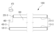
도 7은 본 발명의 제4 실시예에 따른 도어의 횡단면도이다.Figure 7 is a cross-sectional view of a door according to a fourth embodiment of the present invention.
도 7에서 보는 바와 같이, 전면 날개부(120-3)와 후면 날개부(220-3)에 삽입 결합되는 제1 측면 프레임(400-3)에는 가스켓이 삽입되는 가스켓 삽입홈(460)이 마련되도록 제조될 수 있다. 이러한 제1 측면 프레임(400-3)은 복수의 절곡 과정을 거쳐, 가스켓 삽입홈(460)을 형성할 수 있다. 이와 같은 가스켓 삽입홈(460)에 가스켓(470)이 삽입된 도어(1300)는 방음 및 방풍이 효과적으로 이루어질 수 있다.As shown in FIG. 7, the first side frame 400-3 inserted into the front wing 120-3 and the rear wing 220-3 is provided with a
그리고 도 7에서와 같이, 전면 바디부(110-3)와 후면 바디부(210-3)는 서로 다른 폭을 갖도록 제조될 수도 있는 등, 도어(1300)는 다양한 형태로 제조될 수 있다.And as shown in FIG. 7, the front body portion 110-3 and the rear body portion 210-3 may be manufactured to have different widths, and the
도 8은 본 발명의 다양한 도어 구조를 보여주는 예시도이다.Figure 8 is an exemplary diagram showing various door structures of the present invention.
도 8은 또 다른 형태의 도어를 보여주는 것으로, 도어는 도 8의 (a) 내지 (c)에서와 같이 다양한 형태로도 제조될 수 있다. 이와 같이 제조되는 도어는 도어의 테두리에 전면 에지 커버(E1)와 후면 에지 커버(E2)를 형성하도록 제조될 수 있다.Figure 8 shows another type of door, and the door can be manufactured in various forms as shown in Figures 8 (a) to (c). A door manufactured in this way can be manufactured to form a front edge cover (E1) and a rear edge cover (E2) on the border of the door.
그리고 도 8의 (d) 내지 (f)에서 보는 바와 같이, 전면 에지 커버(E1)와 후면 에지 커버(E2)가 형성된 도어는 양개형 문으로도 제조될 수 있음은 물론이다.And as shown in Figures 8 (d) to (f), it goes without saying that the door with the front edge cover (E1) and the rear edge cover (E2) formed can also be manufactured as a double-leaf door.
이와 같이, 도어의 구조 및 형상은 상기에서 언급된 형태로만 한정되는 것은 아니며, 이외의 다양한 형태로도 제조될 수 있음은 물론이다.As such, the structure and shape of the door are not limited to the forms mentioned above, and of course, it can be manufactured in various other forms.
다만, 이는 본 발명의 바람직한 일실시예에 불과할 뿐, 본 발명의 권리 범위가 이러한 실시예의 기재 범위에 의하여 제한되는 것은 아니다.However, this is only a preferred embodiment of the present invention, and the scope of the present invention is not limited by the scope of description of this embodiment.
전술한 본 발명의 설명은 예시를 위한 것이며, 본 발명이 속하는 기술분야의 통상의 지식을 가진 자는 본 발명의 기술적 사상이나 필수적인 특징을 변경하지 않고서 다른 구체적인 형태로 쉽게 변형이 가능하다는 것을 이해할 수 있을 것이다. 그러므로 이상에서 기술한 실시예들은 모든 면에서 예시적인 것이며 한정적이 아닌 것으로 이해해야만 한다. 예를 들어, 단일형으로 설명되어 있는 각 구성 요소는 분산되어 실시될 수도 있으며, 마찬가지로 분산된 것으로 설명되어 있는 구성 요소들도 결합된 형태로 실시될 수 있다.The description of the present invention described above is for illustrative purposes, and those skilled in the art will understand that the present invention can be easily modified into other specific forms without changing the technical idea or essential features of the present invention. will be. Therefore, the embodiments described above should be understood in all respects as illustrative and not restrictive. For example, each component described as unitary may be implemented in a distributed manner, and similarly, components described as distributed may also be implemented in a combined form.
본 발명의 범위는 후술하는 특허청구범위에 의하여 나타내어지며, 특허청구범위의 의미 및 범위 그리고 그 균등 개념으로부터 도출되는 모든 변경 또는 변형된 형태가 본 발명의 범위에 포함되는 것으로 해석되어야 한다.The scope of the present invention is indicated by the patent claims described below, and all changes or modified forms derived from the meaning and scope of the claims and their equivalent concepts should be construed as being included in the scope of the present invention.
100, 100-1, 100-2: 전면 프레임
101: 제1 삽입 공간부
110, 110-1, 110-3: 전면 바디부
120, 120-1, 120-3: 전면 날개부
200, 200-1: 후면 프레임
201: 제2 삽입 공간부
210, 210-1, 210-3: 후면 바디부
220, 220-1, 220-3: 후면 날개부
300: 보강 단열재
400, 400-1, 400-2, 400-3: 제1 측면 프레임
410: 제1 지지부
420: 제2 지지부
430: 제3 지지부
440: 제4 지지부
450: 연결 지지부
460: 가스켓 삽입홈
470: 가스켓
500, 500-1: 제2 측면 프레임
600: 상부 프레임
700: 하부 프레임
810: 제1 장식재
820: 제2 장식재
900: 도어 틀
1000, 1100, 1200, 1300: 도어100, 100-1, 100-2: Front frame
101: first insertion space
110, 110-1, 110-3: Front body part
120, 120-1, 120-3: Front wing section
200, 200-1: Rear frame
201: second insertion space
210, 210-1, 210-3: Rear body part
220, 220-1, 220-3: Rear wing section
300: Reinforced insulation
400, 400-1, 400-2, 400-3: first side frame
410: first support
420: second support
430: third support
440: fourth support
450: connection support
460: Gasket insertion groove
470: gasket
500, 500-1: second side frame
600: upper frame
700: lower frame
810: First decoration material
820: Second decoration material
900: Door frame
1000, 1100, 1200, 1300: Door
Claims (7)
(b) 상기 전면 프레임과 한 쌍을 이루며, 후면 바디부의 테두리 절곡을 통해 후면 날개부를 형성한 후면 프레임을 제조하는 단계;
(c) 상기 전면 바디부와 후면 바디부 사이에 구비되는 보강 단열재를 통해 상기 전면 바디부와 후면 바디부를 일체로 결합하는 단계;
(d) 상기 전면 날개부와 후면 날개부에 슬라이드 삽입되어, 상기 전면 날개부와 후면 날개부에 지지 고정되는 제1 측면 프레임을 통해 도어의 일측면을 마감하는 단계;
(e) 상기 전면 날개부와 후면 날개부에 슬라이드 삽입되어, 상기 전면 날개부와 후면 날개부에 지지 고정되는 제2 측면 프레임을 통해 도어의 타측면을 마감하는 단계;
(f) 상기 전면 날개부와 후면 날개부에 슬라이드 삽입되어, 상기 전면 날개부와 후면 날개부에 지지 고정되는 상부 프레임을 통해 도어의 상부면을 마감하는 단계;
(g) 상기 전면 날개부와 후면 날개부에 슬라이드 삽입되어, 상기 전면 날개부와 후면 날개부에 지지 고정되는 하부 프레임을 통해 도어의 하부면을 마감하는 단계;
(h) 상기 전면 바디부에 제1 장식재를 부착시키는 단계; 및
(i) 상기 후면 바디부에 제2 장식재를 부착시키는 단계를 포함하며,
상기 제1 장식재는 상기 전면 날개부에 슬라이드 삽입된 제1 측면 프레임, 제2 측면 프레임, 상부 프레임 및 하부 프레임을 통해 형성된 전면 에지 커버에 의해 지지 고정되도록 이루어지고,
상기 제2 장식재는 상기 후면 날개부에 슬라이드 삽입된 제1 측면 프레임, 제2 측면 프레임, 상부 프레임 및 하부 프레임을 통해 형성된 후면 에지 커버에 의해 지지 고정되도록 이루어진 것인 도어 제조방법.
(a) manufacturing a front frame forming a front wing portion by bending the edge of the front body portion;
(b) manufacturing a rear frame paired with the front frame and forming a rear wing portion by bending the edge of the rear body portion;
(c) integrally combining the front body portion and the rear body portion through a reinforcing insulating material provided between the front body portion and the rear body portion;
(d) finishing one side of the door through a first side frame that is slidably inserted into the front and rear wings and supported and fixed to the front and rear wings;
(e) finishing the other side of the door through a second side frame that is slidably inserted into the front and rear wings and supported and fixed to the front and rear wings;
(f) finishing the upper surface of the door through an upper frame that is slidably inserted into the front and rear wings and supported and fixed to the front and rear wings;
(g) finishing the lower surface of the door through a lower frame that is slidably inserted into the front and rear wings and supported and fixed to the front and rear wings;
(h) attaching a first decorative material to the front body portion; and
(i) comprising attaching a second decoration material to the rear body portion,
The first decoration material is supported and fixed by a front edge cover formed through a first side frame, a second side frame, an upper frame, and a lower frame slidably inserted into the front wing,
The second decorative material is supported and fixed by a rear edge cover formed through a first side frame, a second side frame, an upper frame, and a lower frame slidably inserted into the rear wing.
상기 (c) 단계 이후로,
(c-1) 상기 보강 단열재의 접착 및 상기 전면 바디부와 후면 바디부의 평단화를 위한 핫프레스 작업을 실시하는 단계를 더 포함하고,
상기 (g) 단계 이후로,
(g-1) 상기 제1 측면 프레임, 제2 측면 프레임, 상부 프레임 및 하부 프레임의 모서리 연결 부위에 포인트 용접을 실시하는 단계를 더 포함하는 것을 특징으로 하는 도어 제조방법.
According to paragraph 1,
After step (c) above,
(c-1) further comprising the step of performing a hot press operation for adhering the reinforcing insulation material and flattening the front body portion and the rear body portion,
After step (g) above,
(g-1) A door manufacturing method further comprising performing point welding on corner connection portions of the first side frame, the second side frame, the upper frame, and the lower frame.
상기 전면 날개부가 상기 보강 단열재가 배치된 반대측 방향인 외측 방향으로 절곡된 상태에서 상기 전면 에지 커버는 상기 제1 장식재가 삽입되는 제1 삽입 공간부를 마련하는 것을 특징으로 하는 도어 제조방법.
According to paragraph 1,
A door manufacturing method, wherein the front edge cover provides a first insertion space into which the first decoration material is inserted while the front wing portion is bent in an outward direction opposite to where the reinforcing insulation material is disposed.
상기 전면 날개부가 상기 보강 단열재가 배치된 내측 방향으로 절곡된 상태에서 상기 전면 에지 커버는 상기 제1 장식재가 삽입되는 제1 삽입 공간부를 마련하되,
상기 제1 측면 프레임, 제2 측면 프레임, 상부 프레임 및 하부 프레임의 절곡을 통해 상기 전면 에지 커버의 높이가 조절되는 것을 특징으로 하는 도어 제조방법.
According to paragraph 1,
In a state where the front wing portion is bent in the inner direction where the reinforcing insulation material is disposed, the front edge cover provides a first insertion space portion into which the first decorative material is inserted,
A door manufacturing method, characterized in that the height of the front edge cover is adjusted by bending the first side frame, the second side frame, the upper frame, and the lower frame.
상기 제1 측면 프레임은,
상기 전면 날개부를 감싸는 제1 지지부;
상기 제1 지지부의 단부로부터 절곡되며, 상기 전면 에지 커버의 높이를 조절하는 제2 지지부;
상기 후면 날개부를 감싸는 제3 지지부;
상기 제3 지지부의 단부로부터 절곡되며, 상기 후면 에지 커버의 높이를 조절하는 제4 지지부; 및
상기 제2 지지부와 제4 지지부를 연결하는 연결 지지부를 포함하는 것을 특징으로 하는 도어 제조방법.
According to paragraph 4,
The first side frame is,
a first support portion surrounding the front wing;
a second support part bent from an end of the first support part and adjusting the height of the front edge cover;
a third support portion surrounding the rear wing portion;
a fourth support part bent from an end of the third support part and adjusting the height of the rear edge cover; and
A door manufacturing method comprising a connecting support part connecting the second support part and the fourth support part.
상기 제1 측면 프레임에는 가스켓이 삽입 고정되는 가스켓 삽입홈이 형성된 것을 특징으로 하는 도어 제조방법.
According to paragraph 1,
A door manufacturing method, characterized in that a gasket insertion groove into which a gasket is inserted and fixed is formed in the first side frame.
상기 보강 단열재는 종이 허니콤, 미네랄울, 글라스울 및 세라크울 중 어느 하나로 이루어지고,
상기 전면 바디부와 후면 바디부는 서로 다른 폭을 갖도록 제조되는 것을 특징으로 하는 도어 제조방법.According to paragraph 1,
The reinforcing insulation material is made of any one of paper honeycomb, mineral wool, glass wool, and ceramic wool,
A door manufacturing method, characterized in that the front body portion and the rear body portion are manufactured to have different widths.
Priority Applications (1)
| Application Number | Priority Date | Filing Date | Title |
|---|---|---|---|
| KR1020220028839A KR20230131663A (en) | 2022-03-07 | 2022-03-07 | Manufacturing method of door |
Applications Claiming Priority (1)
| Application Number | Priority Date | Filing Date | Title |
|---|---|---|---|
| KR1020220028839A KR20230131663A (en) | 2022-03-07 | 2022-03-07 | Manufacturing method of door |
Publications (1)
| Publication Number | Publication Date |
|---|---|
| KR20230131663A true KR20230131663A (en) | 2023-09-14 |
Family
ID=88014076
Family Applications (1)
| Application Number | Title | Priority Date | Filing Date |
|---|---|---|---|
| KR1020220028839A KR20230131663A (en) | 2022-03-07 | 2022-03-07 | Manufacturing method of door |
Country Status (1)
| Country | Link |
|---|---|
| KR (1) | KR20230131663A (en) |
Citations (1)
| Publication number | Priority date | Publication date | Assignee | Title |
|---|---|---|---|---|
| KR20140135289A (en) | 2013-05-15 | 2014-11-26 | 금일금속(주) | A door and the manufacturing process with ornament of jewelry |
-
2022
- 2022-03-07 KR KR1020220028839A patent/KR20230131663A/en not_active Application Discontinuation
Patent Citations (1)
| Publication number | Priority date | Publication date | Assignee | Title |
|---|---|---|---|---|
| KR20140135289A (en) | 2013-05-15 | 2014-11-26 | 금일금속(주) | A door and the manufacturing process with ornament of jewelry |
Similar Documents
| Publication | Publication Date | Title |
|---|---|---|
| JP5721811B2 (en) | ASSEMBLY WALL HAVING IMPROVED SOUND ABSORPTION PERFORMANCE AND ITS ASSEMBLY STRUCTURE | |
| KR101870772B1 (en) | Fire door structure having a improved fireproof and durability and manufacturing method thereof | |
| US8171684B2 (en) | Glass wall | |
| KR102275607B1 (en) | Triple panel structure with fire resistance, heat insulation, and sound absorption | |
| KR20230131663A (en) | Manufacturing method of door | |
| KR100604411B1 (en) | The construction method of prefabricated partition with cavity wall using composition panels | |
| KR20230131664A (en) | Door | |
| KR20160109746A (en) | A fireproof-door with fire-resistance intumescent sheet | |
| JP2018087424A (en) | Panel unit and curtain wall equipped with the same | |
| KR200449221Y1 (en) | Fireproof interior door | |
| WO2015149372A1 (en) | Combined wall and construction method therefor | |
| KR102039141B1 (en) | Insulation window and construction method thereof | |
| KR200466621Y1 (en) | Assembly device for ceiling panel | |
| KR20070082479A (en) | Window for higher stories | |
| KR20220089597A (en) | Noise Structure Between Floors Using Elastic Materials | |
| KR200368017Y1 (en) | An Entrance Door | |
| KR102419636B1 (en) | Architectural marble panels | |
| KR101281365B1 (en) | Wood type fireproof door | |
| KR20020036692A (en) | Fire and soundproof panel | |
| JP2003027705A (en) | Connecting and fixing structure of metal sandwich panel | |
| KR20090078189A (en) | Wood type fireproof door | |
| CN219138111U (en) | Interior trim furred ceiling subassembly and have its modularization house | |
| KR102566185B1 (en) | Interior and exterior finishing materials with improved non-combustibility and manufacturing method therefor | |
| JP2023157242A (en) | Fire and heat resistant panel and manufacturing method of the same | |
| JP7273553B2 (en) | Building panel, building panel unit, mounting structure of building panel |
Legal Events
| Date | Code | Title | Description |
|---|---|---|---|
| E902 | Notification of reason for refusal |