KR20230107360A - How to prevent slipping in diverters and submersible pumps - Google Patents
How to prevent slipping in diverters and submersible pumps Download PDFInfo
- Publication number
- KR20230107360A KR20230107360A KR1020237021032A KR20237021032A KR20230107360A KR 20230107360 A KR20230107360 A KR 20230107360A KR 1020237021032 A KR1020237021032 A KR 1020237021032A KR 20237021032 A KR20237021032 A KR 20237021032A KR 20230107360 A KR20230107360 A KR 20230107360A
- Authority
- KR
- South Korea
- Prior art keywords
- flow path
- gas
- suction
- submersible pump
- suction container
- Prior art date
Links
- 239000007789 gas Substances 0.000 claims abstract description 155
- 238000000034 method Methods 0.000 claims abstract description 18
- 238000010926 purge Methods 0.000 claims description 34
- 238000009835 boiling Methods 0.000 claims description 3
- 238000006243 chemical reaction Methods 0.000 claims description 3
- 239000011261 inert gas Substances 0.000 claims description 3
- 238000003825 pressing Methods 0.000 claims description 3
- 238000004891 communication Methods 0.000 claims 1
- QGZKDVFQNNGYKY-UHFFFAOYSA-N Ammonia Chemical compound N QGZKDVFQNNGYKY-UHFFFAOYSA-N 0.000 abstract description 20
- IJGRMHOSHXDMSA-UHFFFAOYSA-N Atomic nitrogen Chemical compound N#N IJGRMHOSHXDMSA-UHFFFAOYSA-N 0.000 abstract description 10
- 239000001257 hydrogen Substances 0.000 abstract description 10
- 229910052739 hydrogen Inorganic materials 0.000 abstract description 10
- 239000007788 liquid Substances 0.000 abstract description 10
- 229910021529 ammonia Inorganic materials 0.000 abstract description 9
- 239000003949 liquefied natural gas Substances 0.000 abstract description 9
- VGGSQFUCUMXWEO-UHFFFAOYSA-N Ethene Chemical compound C=C VGGSQFUCUMXWEO-UHFFFAOYSA-N 0.000 abstract description 4
- 239000005977 Ethylene Substances 0.000 abstract description 4
- 239000003915 liquefied petroleum gas Substances 0.000 abstract description 4
- 229910052757 nitrogen Inorganic materials 0.000 abstract description 4
- 125000004435 hydrogen atom Chemical class [H]* 0.000 abstract 1
- 238000010586 diagram Methods 0.000 description 10
- VNWKTOKETHGBQD-UHFFFAOYSA-N methane Chemical compound C VNWKTOKETHGBQD-UHFFFAOYSA-N 0.000 description 10
- UFHFLCQGNIYNRP-UHFFFAOYSA-N Hydrogen Chemical compound [H][H] UFHFLCQGNIYNRP-UHFFFAOYSA-N 0.000 description 7
- 239000003345 natural gas Substances 0.000 description 5
- 238000001816 cooling Methods 0.000 description 4
- 150000002431 hydrogen Chemical class 0.000 description 4
- CURLTUGMZLYLDI-UHFFFAOYSA-N Carbon dioxide Chemical compound O=C=O CURLTUGMZLYLDI-UHFFFAOYSA-N 0.000 description 2
- 229910001873 dinitrogen Inorganic materials 0.000 description 2
- 239000012530 fluid Substances 0.000 description 2
- 238000010248 power generation Methods 0.000 description 2
- 238000005086 pumping Methods 0.000 description 2
- 238000001179 sorption measurement Methods 0.000 description 2
- 239000000126 substance Substances 0.000 description 2
- 238000009834 vaporization Methods 0.000 description 2
- 230000008016 vaporization Effects 0.000 description 2
- 229910002092 carbon dioxide Inorganic materials 0.000 description 1
- 239000001569 carbon dioxide Substances 0.000 description 1
- 239000013064 chemical raw material Substances 0.000 description 1
- 238000001035 drying Methods 0.000 description 1
- 239000000446 fuel Substances 0.000 description 1
- 239000001307 helium Substances 0.000 description 1
- 229910052734 helium Inorganic materials 0.000 description 1
- SWQJXJOGLNCZEY-UHFFFAOYSA-N helium atom Chemical compound [He] SWQJXJOGLNCZEY-UHFFFAOYSA-N 0.000 description 1
- 230000002265 prevention Effects 0.000 description 1
- 238000010792 warming Methods 0.000 description 1
Images


Classifications
-
- F—MECHANICAL ENGINEERING; LIGHTING; HEATING; WEAPONS; BLASTING
- F04—POSITIVE - DISPLACEMENT MACHINES FOR LIQUIDS; PUMPS FOR LIQUIDS OR ELASTIC FLUIDS
- F04D—NON-POSITIVE-DISPLACEMENT PUMPS
- F04D7/00—Pumps adapted for handling specific fluids, e.g. by selection of specific materials for pumps or pump parts
- F04D7/02—Pumps adapted for handling specific fluids, e.g. by selection of specific materials for pumps or pump parts of centrifugal type
-
- F—MECHANICAL ENGINEERING; LIGHTING; HEATING; WEAPONS; BLASTING
- F04—POSITIVE - DISPLACEMENT MACHINES FOR LIQUIDS; PUMPS FOR LIQUIDS OR ELASTIC FLUIDS
- F04D—NON-POSITIVE-DISPLACEMENT PUMPS
- F04D13/00—Pumping installations or systems
- F04D13/02—Units comprising pumps and their driving means
- F04D13/06—Units comprising pumps and their driving means the pump being electrically driven
- F04D13/08—Units comprising pumps and their driving means the pump being electrically driven for submerged use
- F04D13/10—Units comprising pumps and their driving means the pump being electrically driven for submerged use adapted for use in mining bore holes
-
- F—MECHANICAL ENGINEERING; LIGHTING; HEATING; WEAPONS; BLASTING
- F04—POSITIVE - DISPLACEMENT MACHINES FOR LIQUIDS; PUMPS FOR LIQUIDS OR ELASTIC FLUIDS
- F04D—NON-POSITIVE-DISPLACEMENT PUMPS
- F04D13/00—Pumping installations or systems
- F04D13/02—Units comprising pumps and their driving means
- F04D13/06—Units comprising pumps and their driving means the pump being electrically driven
- F04D13/08—Units comprising pumps and their driving means the pump being electrically driven for submerged use
- F04D13/086—Units comprising pumps and their driving means the pump being electrically driven for submerged use the pump and drive motor are both submerged
-
- F—MECHANICAL ENGINEERING; LIGHTING; HEATING; WEAPONS; BLASTING
- F04—POSITIVE - DISPLACEMENT MACHINES FOR LIQUIDS; PUMPS FOR LIQUIDS OR ELASTIC FLUIDS
- F04D—NON-POSITIVE-DISPLACEMENT PUMPS
- F04D15/00—Control, e.g. regulation, of pumps, pumping installations or systems
- F04D15/0005—Control, e.g. regulation, of pumps, pumping installations or systems by using valves
- F04D15/0011—Control, e.g. regulation, of pumps, pumping installations or systems by using valves by-pass valves
-
- F—MECHANICAL ENGINEERING; LIGHTING; HEATING; WEAPONS; BLASTING
- F04—POSITIVE - DISPLACEMENT MACHINES FOR LIQUIDS; PUMPS FOR LIQUIDS OR ELASTIC FLUIDS
- F04D—NON-POSITIVE-DISPLACEMENT PUMPS
- F04D29/00—Details, component parts, or accessories
- F04D29/40—Casings; Connections of working fluid
- F04D29/42—Casings; Connections of working fluid for radial or helico-centrifugal pumps
- F04D29/44—Fluid-guiding means, e.g. diffusers
- F04D29/445—Fluid-guiding means, e.g. diffusers especially adapted for liquid pumps
-
- F—MECHANICAL ENGINEERING; LIGHTING; HEATING; WEAPONS; BLASTING
- F04—POSITIVE - DISPLACEMENT MACHINES FOR LIQUIDS; PUMPS FOR LIQUIDS OR ELASTIC FLUIDS
- F04D—NON-POSITIVE-DISPLACEMENT PUMPS
- F04D9/00—Priming; Preventing vapour lock
- F04D9/001—Preventing vapour lock
- F04D9/002—Preventing vapour lock by means in the very pump
- F04D9/003—Preventing vapour lock by means in the very pump separating and removing the vapour
-
- F—MECHANICAL ENGINEERING; LIGHTING; HEATING; WEAPONS; BLASTING
- F04—POSITIVE - DISPLACEMENT MACHINES FOR LIQUIDS; PUMPS FOR LIQUIDS OR ELASTIC FLUIDS
- F04D—NON-POSITIVE-DISPLACEMENT PUMPS
- F04D1/00—Radial-flow pumps, e.g. centrifugal pumps; Helico-centrifugal pumps
- F04D1/06—Multi-stage pumps
-
- F—MECHANICAL ENGINEERING; LIGHTING; HEATING; WEAPONS; BLASTING
- F05—INDEXING SCHEMES RELATING TO ENGINES OR PUMPS IN VARIOUS SUBCLASSES OF CLASSES F01-F04
- F05D—INDEXING SCHEME FOR ASPECTS RELATING TO NON-POSITIVE-DISPLACEMENT MACHINES OR ENGINES, GAS-TURBINES OR JET-PROPULSION PLANTS
- F05D2250/00—Geometry
- F05D2250/50—Inlet or outlet
- F05D2250/52—Outlet
Landscapes
- Engineering & Computer Science (AREA)
- Mechanical Engineering (AREA)
- General Engineering & Computer Science (AREA)
- Mining & Mineral Resources (AREA)
- Structures Of Non-Positive Displacement Pumps (AREA)
Abstract
본 발명은 액화 암모니아, 액체 수소, 액체 질소, 액화 천연가스, 액화 에틸렌 가스, 액화 석유 가스 등의 액화 가스를 이송하는 용도로 사용되는 잠몰식 펌프의 공전을 방지하기 위한 기술에 관한 것이다. 유로 전환 장치(5)는 제1 유로(41), 제2 유로(42), 및 제3 유로(43)를 갖는 유로 구조체(45)와, 유로 구조체(45) 내에 배치되고, 제3 유로(43)를 제1 유로(41) 또는 제2 유로(42) 중 어느 것에 선택적으로 연통시키는 밸브체(47)를 구비하고 있고, 제1 유로(41)는 잠몰식 펌프(1)의 토출구(1b)에 연통하고, 제2 유로(42)는 흡입 용기(2)의 내부에 연통하고, 제3 유로(43)는 흡입 용기(2)의 토출 포트(8)에 연통한다.The present invention relates to a technique for preventing idleness of a submersible pump used for transporting liquefied gases such as liquefied ammonia, liquid hydrogen, liquid nitrogen, liquefied natural gas, liquefied ethylene gas, and liquefied petroleum gas. The flow path switching device 5 includes a flow path structure 45 having a first flow path 41, a second flow path 42, and a third flow path 43, disposed in the flow path structure 45, and a third flow path ( 43) is provided with a valve body 47 selectively communicating with either the first flow path 41 or the second flow path 42, and the first flow path 41 is the discharge port 1b of the submersible pump 1 ), the second flow path 42 communicates with the inside of the suction container 2, and the third flow path 43 communicates with the discharge port 8 of the suction container 2.
Description
본 발명은 액화 암모니아, 액체 수소, 액체 질소, 액화 천연가스, 액화 에틸렌 가스, 액화 석유 가스 등의 액화 가스를 이송하는 용도로 사용되는 잠몰식 펌프의 공전을 방지하기 위한 기술에 관한 것이다.The present invention relates to a technique for preventing idleness of a submersible pump used for transporting liquefied gases such as liquefied ammonia, liquid hydrogen, liquid nitrogen, liquefied natural gas, liquefied ethylene gas, and liquefied petroleum gas.
천연가스는, 화력 발전이나 화학 원료로서 널리 이용되고 있다. 또한, 암모니아나 수소는, 지구 온난화의 원인이 되는 이산화탄소를 발생시키지 않는 에너지로서 기대되고 있다. 에너지로서의 수소의 용도에는, 연료 전지 및 터빈 발전 등을 들 수 있다. 천연가스, 암모니아 및 수소는, 상온에서는 기체의 상태이기 때문에, 이들의 저장 및 운반을 위해, 천연가스, 암모니아 및 수소는 냉각되어, 액화된다. 액화 천연가스(LNG)나 액화 암모니아나 액체 수소 등의 액화 가스는, 일단 액화 가스 저류조에 저장된 후, 펌프에 의해 발전소나 공장 등에 이송된다.Natural gas is widely used for thermal power generation and as a chemical raw material. Further, ammonia and hydrogen are expected as energy that does not generate carbon dioxide, which causes global warming. Uses of hydrogen as energy include fuel cells and turbine power generation. Since natural gas, ammonia, and hydrogen are in a gaseous state at room temperature, for their storage and transportation, natural gas, ammonia, and hydrogen are cooled and liquefied. BACKGROUND OF THE INVENTION Liquefied gases such as liquefied natural gas (LNG), liquefied ammonia, and liquid hydrogen are once stored in a liquefied gas storage tank and then transported to a power plant or a factory by a pump.
도 12는 액화 가스를 퍼 올리기 위한 펌프 시스템의 종래 예를 나타내는 모식도이다. 펌프(500)는 액화 가스가 저장된 액화 가스 저류조(도시하지 않음)에 접속된 종형 흡입 용기(505) 내에 설치된다. 액화 가스는, 흡입 포트(501)를 통해 흡입 용기(505) 내에 도입되고, 흡입 용기(505) 내는 액화 가스로 채워진다. 펌프(500)의 전체는 액화 가스 중에 침지된다. 따라서, 펌프(500)는 액화 가스 중에서 운전 가능한 잠몰식 펌프이다. 펌프(500)가 운전되면, 액화 가스는 펌프(500)에 의해 토출 포트(502)를 통해 배출된다. 펌프(500)의 운전 중, 흡입 용기(505) 내의 액화 가스의 일부는 기화되어 가스가 되고, 이 가스는 벤트 라인(503)을 통해 흡입 용기(505)로부터 배출된다.12 is a schematic diagram showing a conventional example of a pump system for pumping up liquefied gas. The
펌프(500)를 운전하기 전, 흡입 용기(505)로부터 공기를 퍼지 가스에 의해 배제하는 드라이업과, 펌프(500)를 액화 가스로 냉각하는 쿨다운이 행해진다. 흡입 용기(505) 내에 존재하는 공기가 초저온의 액화 가스에 접촉하면, 공기 중의 수분이 액화 가스에 의해 냉각되어 응고되어, 펌프(500)의 회전 동작을 저해해 버린다. 또한, 펌프(500)의 시동 시에 펌프(500)가 상온이면, 초저온의 액화 가스가 펌프(500)에 접촉했을 때 액화 가스가 기화되어 버린다. 이러한 사상을 방지하기 위해, 펌프(500)의 운전 전에는 드라이업 및 쿨다운이 행해진다.Before operating the
드라이업은, 흡입 용기(505) 내에 퍼지 가스(예를 들어, 질소 가스)를 주입함으로써 행해지고, 쿨다운은, 흡입 용기(505) 내에 액화 가스(예를 들어, 액화 천연가스)를 주입함으로써 행해진다. 흡입 용기(505) 내에 주입된 퍼지 가스 또는 액화 가스는, 흡입 용기(505)를 채우고, 펌프(500)의 흡입구(500a)로부터 펌프(500) 내로 유입되고, 그리고, 토출 포트(502)를 통해 배출된다.Dry-up is performed by injecting a purge gas (eg, nitrogen gas) into the
그러나, 드라이업을 위해 흡입 용기(505) 내에 공급된 퍼지 가스는, 펌프(500) 내를 흘러, 펌프(500)를 공전시키는 경우가 있다. 펌프(500)가 공전하면, 베어링 등의 미끄럼 이동부를 손상시켜 버린다. 또한, 쿨다운을 위해 흡입 용기(505) 내에 공급된 액화 가스는, 상온의 펌프(500)에 접촉하여 대량의 가스를 발생시킨다. 이 가스는, 펌프(500)의 임펠러를 공전시켜, 베어링 등의 미끄럼 이동부를 손상시켜 버리는 경우가 있다.However, the purge gas supplied into the
이에 따라, 본 발명은 펌프의 드라이업, 쿨다운 등의 목적으로 흡입 용기 내에 도입된 가스가 펌프를 공전시키는 것을 방지할 수 있는 유로 전환 장치를 제공한다. 또한, 본 발명은 잠몰식 펌프의 공전을 방지하기 위한 방법을 제공한다.Accordingly, the present invention provides a flow path switching device capable of preventing the pump from idling by gas introduced into the suction container for the purpose of dry-up or cool-down of the pump. In addition, the present invention provides a method for preventing idleness of a submersible pump.
일 양태에서는, 액화 가스를 이송하기 위해 사용되고, 또한 흡입 용기 내에 배치된 잠몰식 펌프의 공전을 방지하기 위한 유로 전환 장치이며, 제1 유로, 제2 유로, 및 제3 유로를 갖는 유로 구조체와, 상기 유로 구조체 내에 배치되고, 상기 제3 유로를 상기 제1 유로 또는 상기 제2 유로 중 어느 것에 선택적으로 연통시키는 밸브체를 구비하고 있고, 상기 제1 유로는, 상기 잠몰식 펌프의 토출구에 연통하고, 상기 제2 유로는, 상기 흡입 용기의 내부에 연통하고, 상기 제3 유로는, 상기 흡입 용기의 토출 포트에 연통하는, 유로 전환 장치가 제공된다.In one aspect, a flow path switching device used for transporting liquefied gas and preventing revolution of a submersible pump disposed in a suction container, comprising: a flow path structure having a first flow path, a second flow path, and a third flow path; a valve body disposed within the flow path structure and selectively communicating the third flow path with either the first flow path or the second flow path; wherein the first flow path communicates with an outlet of the submersible pump; , wherein the second flow path communicates with the inside of the suction container, and the third flow path communicates with a discharge port of the suction container.
일 양태에서는, 상기 유로 구조체는, 상기 제1 유로와 상기 제3 유로를 연통시키는 바이패스 유로를 더 구비하고 있고, 상기 바이패스 유로의 단면적은, 상기 제1 유로의 단면적보다 작다.In one aspect, the flow path structure further includes a bypass flow path that communicates the first flow path and the third flow path, and a cross-sectional area of the bypass flow path is smaller than that of the first flow path.
일 양태에서는, 상기 바이패스 유로의 단면적은, 상기 밸브체가 상기 제1 유로를 닫고, 또한 기체가 상기 잠몰식 펌프 및 상기 바이패스 유로를 흐를 때, 상기 잠몰식 펌프의 임펠러가 상기 기체의 흐름에 의해 회전하지 않는 단면적이다.In one aspect, the cross-sectional area of the bypass flow path is such that when the valve body closes the first flow path and gas flows through the submersible pump and the bypass flow path, the impeller of the submersible pump is affected by the flow of the gas. is the cross-sectional area that is not rotated by
일 양태에서는, 상기 밸브체를 상기 유로 구조체에 대하여 압박 접촉시켜 상기 제1 유로를 닫는 스프링을 더 구비하고 있다.In one aspect, a spring for pressing the valve element into contact with the flow path structure to close the first flow path is further provided.
일 양태에서는, 액화 가스를 이송하기 위한 잠몰식 펌프와, 상기 잠몰식 펌프가 내부에 수용된 흡입 용기와, 상기 잠몰식 펌프의 공전을 방지하기 위한 상기 유로 전환 장치를 구비하고 있는, 펌프 시스템이 제공된다.In one aspect, a pump system is provided, including a submersible pump for transporting liquefied gas, a suction container in which the submersible pump is accommodated, and the flow path conversion device for preventing the idling of the submersible pump. Provided do.
일 양태에서는, 상기 펌프 시스템은, 상기 잠몰식 펌프의 회전을 검출하는 회전 검출기를 더 구비하고 있다.In one aspect, the pump system further includes a rotation detector for detecting rotation of the submersible pump.
일 양태에서는, 상기 펌프 시스템은, 상기 잠몰식 펌프의 회전을 방지하는 회전 방지 장치를 더 구비하고 있다.In one aspect, the pump system further includes a rotation prevention device for preventing rotation of the submersible pump.
일 양태에서는, 액화 가스를 이송하기 위해 사용되고, 또한 흡입 용기 내에 배치된 잠몰식 펌프의 공전을 방지하기 위한 방법이며, 상기 잠몰식 펌프의 토출구에 연통하는 제1 유로를 밸브체로 닫고, 또한 상기 흡입 용기의 내부에 연통하는 제2 유로와, 상기 흡입 용기의 토출 포트에 연통하는 제3 유로가 연통한 상태에서, 액화 가스를 상기 흡입 용기 내에 공급하고, 상기 흡입 용기 내에서 발생한 가스를 상기 제2 유로 및 상기 제3 유로를 통해 상기 토출 포트에 이송하는, 방법이 제공된다.In one aspect, there is provided a method for preventing revolution of a submersible pump used for transporting liquefied gas and disposed in a suction container, wherein a first flow path communicating with an outlet of the submersible pump is closed with a valve body, and the suction In a state in which the second flow path communicating with the inside of the container and the third flow path communicating with the discharge port of the suction container communicate with each other, liquefied gas is supplied into the suction container, and the gas generated in the suction container is discharged into the second passage. A method of transferring to the discharge port through a flow path and the third flow path is provided.
일 양태에서는, 상기 방법은, 상기 액화 가스를 상기 흡입 용기 내에 공급하기 전에, 퍼지 가스를 상기 흡입 용기 내에 공급하는 공정을 더 포함한다.In one aspect, the method further includes a step of supplying a purge gas into the suction container before supplying the liquefied gas into the suction container.
일 양태에서는, 상기 퍼지 가스는, 상기 흡입 용기의 흡입 포트를 통해 상기 흡입 용기 내에 공급되고, 상기 흡입 용기의 저부에 접속된 드레인 라인을 통해 배출되고, 상기 흡입 포트는 상기 흡입 용기의 저부보다 높은 위치에 있다.In one aspect, the purge gas is supplied into the suction container through a suction port of the suction container and discharged through a drain line connected to a bottom of the suction container, and the suction port is higher than the bottom of the suction container. is in position
일 양태에서는, 상기 퍼지 가스는, 상기 흡입 용기의 흡입 포트를 통해 상기 흡입 용기 내에 공급되고, 상기 제2 유로, 상기 제3 유로, 및 상기 토출 포트를 통해 배출된다.In one aspect, the purge gas is supplied into the suction container through a suction port of the suction container and discharged through the second flow passage, the third flow passage, and the discharge port.
일 양태에서는, 상기 퍼지 가스는, 상기 흡입 용기의 저부에 접속된 드레인 라인을 통해 상기 흡입 용기 내에 공급되고, 상기 제2 유로, 상기 제3 유로, 및 상기 토출 포트를 통해 배출된다.In one aspect, the purge gas is supplied into the suction container through a drain line connected to a bottom of the suction container, and discharged through the second flow passage, the third flow passage, and the discharge port.
일 양태에서는, 상기 퍼지 가스는, 상기 액화 가스를 구성하는 원소보다 낮은 비점을 갖는 원소로 이루어지는 불활성 가스이다.In one aspect, the purge gas is an inert gas composed of an element having a lower boiling point than an element constituting the liquefied gas.
일 양태에서는, 상기 방법은, 상기 제2 유로를 상기 밸브체로 닫고, 또한 상기 제1 유로와 상기 제3 유로가 연통한 상태에서, 상기 잠몰식 펌프를 운전하는 공정을 더 포함한다.In one aspect, the method further includes a step of closing the second flow path with the valve body and operating the submersible pump in a state where the first flow path and the third flow path communicate with each other.
일 양태에서는, 상기 방법은, 상기 흡입 용기 내에서 발생한 가스를, 상기 토출 포트를 통해 가스 처리 장치로 유도하는 공정을 더 포함한다.In one aspect, the method further includes a step of guiding the gas generated in the suction container to a gas treatment device through the discharge port.
본 발명에 의하면, 드라이업, 쿨다운 시에 흡입 용기 내에 도입된 가스(퍼지 가스, 액화 가스로부터 발생한 가스 등)는 유로 전환 장치에 의해 잠몰식 펌프 내에는 도입되지 않고, 토출 포트로 유도된다. 따라서, 잠몰식 펌프의 임펠러가 공전하지 않고, 결과적으로 잠몰식 펌프의 베어링 등의 미끄럼 이동부의 손상을 방지할 수 있다.According to the present invention, gases introduced into the suction container during dry-up and cool-down (purge gas, gas generated from liquefied gas, etc.) are guided to the discharge port without being introduced into the submersible pump by the flow path switching device. Therefore, the impeller of the submersible pump does not revolve, and as a result, damage to sliding parts such as bearings of the submersible pump can be prevented.
도 1은 액화 가스를 이송하기 위한 펌프 시스템의 일 실시 형태를 나타내는 도면이다.
도 2는 유로 전환 장치의 상세한 구성의 일 실시 형태를 나타내는 단면도이다.
도 3은 잠몰식 펌프가 운전하고 있을 때의 유로 전환 장치의 상태를 나타내고 있다.
도 4는 드라이업의 일 실시 형태를 설명하기 위한 도면이다.
도 5는 드라이업의 다른 실시 형태를 설명하기 위한 도면이다.
도 6은 드라이업의 또 다른 실시 형태를 설명하기 위한 도면이다.
도 7은 쿨다운의 일 실시 형태를 설명하기 위한 도면이다.
도 8은 복수의 잠몰식 펌프를 동시에 냉각하는 일 실시 형태를 설명하기 위한 도면이다.
도 9는 유로 전환 장치의 다른 실시 형태를 나타내는 단면도이다.
도 10은 회전 검출기를 구비한 펌프 시스템의 일 실시 형태를 나타내는 도면이다.
도 11은 회전 방지 장치를 구비한 펌프 시스템의 일 실시 형태를 나타내는 도면이다.
도 12는 액화 가스를 퍼 올리기 위한 펌프 시스템의 종래 예를 나타내는 모식도이다.1 is a diagram showing one embodiment of a pump system for transporting liquefied gas.
Fig. 2 is a cross-sectional view showing an embodiment of a detailed configuration of a flow path switching device.
Fig. 3 shows the state of the flow path switching device when the submersible pump is operating.
4 is a diagram for explaining an embodiment of dry-up.
5 is a diagram for explaining another embodiment of dry-up.
6 is a diagram for explaining another embodiment of dry-up.
7 is a diagram for explaining an embodiment of cooldown.
8 is a view for explaining an embodiment of simultaneously cooling a plurality of submersible pumps.
Fig. 9 is a cross-sectional view showing another embodiment of the flow path switching device.
10 is a diagram showing one embodiment of a pump system with a rotation detector.
11 is a diagram showing an embodiment of a pump system with an anti-rotation device.
12 is a schematic diagram showing a conventional example of a pump system for pumping up liquefied gas.
이하, 본 발명의 실시 형태에 대하여 도면을 참조하여 설명한다. 도 1은 액화 가스를 이송하기 위한 펌프 시스템의 일 실시 형태를 나타내는 도면이다. 도 1에 나타내는 펌프 시스템에 의해 이송되는 액화 가스의 예로서는, 액화 암모니아, 액체 수소, 액체 질소, 액화 천연가스, 액화 에틸렌 가스, 액화 석유 가스 등을 들 수 있다.EMBODIMENT OF THE INVENTION Hereinafter, embodiment of this invention is described with reference to drawings. 1 is a diagram showing one embodiment of a pump system for transporting liquefied gas. Examples of the liquefied gas transported by the pump system shown in FIG. 1 include liquefied ammonia, liquid hydrogen, liquid nitrogen, liquefied natural gas, liquefied ethylene gas, and liquefied petroleum gas.
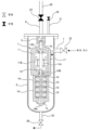
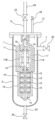
도 1에 나타내는 바와 같이, 펌프 시스템은, 액화 가스를 이송하기 위한 잠몰식 펌프(1)와, 잠몰식 펌프(1)가 내부에 수용된 흡입 용기(2)와, 잠몰식 펌프(1)의 공전을 방지하기 위한 유로 전환 장치(5)를 구비하고 있다. 흡입 용기(2)는 흡입 포트(7) 및 토출 포트(8)를 갖고 있다. 액화 가스는, 흡입 포트(7)를 통해 흡입 용기(2) 내에 도입되고, 흡입 용기(2) 내는 액화 가스로 채워진다. 잠몰식 펌프(1)의 운전 중, 잠몰식 펌프(1)의 전체는 액화 가스 중에 침지된다. 따라서, 잠몰식 펌프(1)는 액화 가스 중에서 운전 가능하도록 구성되어 있다.As shown in FIG. 1, the pump system consists of a
잠몰식 펌프(1)는 모터 로터(11A) 및 모터 스테이터(11B)를 갖는 전동기(11)와, 전동기(11)에 연결된 회전축(12)과, 회전축(12)을 회전 가능하게 지지하는 베어링(14A, 14B, 14C)과, 회전축(12)에 고정된 임펠러(15)와, 임펠러(15)를 수용하는 펌프 케이싱(16)을 갖는다. 유로 전환 장치(5)는 흡입 용기(2) 내에 배치되어 있다. 보다 구체적으로는, 유로 전환 장치(5)는 잠몰식 펌프(1)의 토출구(1b) 및 흡입 용기(2)의 토출 포트(8)의 양쪽에 연결되어 있다. 유로 전환 장치(5)의 구체적 구성에 대해서는 후술한다.The
전력 케이블(도시하지 않음)을 통해 전력이 전동기(11)에 공급되면, 전동기(11)는 회전축(12) 및 임펠러(15)를 일체로 회전시킨다. 임펠러(15)의 회전에 수반하여, 액화 가스는 흡입구(1a)로부터 잠몰식 펌프(1) 내에 흡입되고, 토출 유로(17) 및 토출구(1b)를 통해 유로 전환 장치(5) 내에 토출된다. 또한, 액화 가스는, 유로 전환 장치(5) 내를 흘러, 흡입 용기(2)의 토출 포트(8) 내로 유입된다. 토출 포트(8)에는, 토출관(20)이 연결되어 있고, 토출 포트(8)를 흐른 액화 가스는, 토출관(20)을 통해 이송된다.When electric power is supplied to the
흡입 포트(7)에는 흡입 밸브(22)가 접속되고, 토출 포트(8)에는 토출 밸브(23)가 접속되어 있다. 흡입 용기(2)의 저부에는 드레인 라인(25)이 접속되고, 드레인 라인(25)에는 드레인 밸브(26)가 접속되어 있다. 흡입 포트(7)는 흡입 용기(2)의 측벽에 마련되어 있고, 흡입 용기(2)의 저부보다 높은 위치에 있다. 토출 포트(8)는 흡입 용기(2)의 상부에 마련되어 있고, 흡입 포트(7)보다 높은 위치에 있다. 잠몰식 펌프(1)의 운전 중에는, 흡입 밸브(22) 및 토출 밸브(23)는 열리고, 드레인 밸브(26)는 닫혀 있다. 흡입 용기(2)의 상부에는 벤트 라인(31)이 접속되어 있다. 잠몰식 펌프(1)의 운전 중, 액화 가스의 일부는 잠몰식 펌프(1)의 발열에 기인하여 기화되어 가스가 되고, 이 가스는 벤트 라인(31)을 통해 흡입 용기(2)로부터 배출된다. 벤트 라인(31)에는 벤트 밸브(32)가 접속되어 있다. 일 실시 형태에서는, 이 가스를, 벤트 라인(31)을 통해 가스 처리 장치(도시하지 않음)로 유도해도 된다. 가스 처리 장치는, 액화 가스로부터 기화된 가스(예를 들어 천연가스 또는 수소 가스 또는 암모니아 가스)를 처리하는 장치이다. 가스 처리 장치의 예로서는, 가스 소각 장치(플레어링 장치), 화학적 가스 처리 장치, 가스 흡착 장치 등을 들 수 있다.A
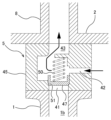
도 2는 유로 전환 장치(5)의 상세한 구성의 일 실시 형태를 나타내는 단면도이다. 도 2에 나타내는 바와 같이, 유로 전환 장치(5)는 제1 유로(41), 제2 유로(42), 및 제3 유로(43)를 갖는 유로 구조체(45)와, 유로 구조체(45) 내에 배치된 밸브체(47)를 구비하고 있다. 제1 유로(41)는 잠몰식 펌프(1)의 토출구(1b)에 연통하고, 제2 유로(42)는 흡입 용기(2)의 내부에 연통하고, 제3 유로(43)는 흡입 용기(2)의 토출 포트(8)에 연통하고 있다. 밸브체(47)는 제3 유로(43)를 제1 유로(41) 또는 제2 유로(42) 중 어느 것에 선택적으로 연통시키도록 배치되어 있다. 유로 전환 장치(5)의 구성은, 그 의도한 기능이 발휘 가능한 한, 도 2에 나타내는 실시 형태에 한정되지는 않는다.2 is a cross-sectional view showing one embodiment of the detailed configuration of the flow
도 2는 잠몰식 펌프(1)가 운전하고 있지 않을 때의 유로 전환 장치(5)의 상태를 나타내고 있다. 밸브체(47)는 스프링(50)에 의해 유로 구조체(45)에 대하여 압박 접촉되어 제1 유로(41)를 닫는다. 보다 구체적으로는, 유로 구조체(45)는 제1 유로(41)의 출구의 주위에 형성된 밸브 시트(51)를 갖고 있고, 밸브체(47)는 스프링(50)에 의해 밸브 시트(51)에 압박 접촉된다. 따라서, 밸브체(47)가 밸브 시트(51)에 압박 접촉되고 있는 동안은, 제1 유로(41)는 닫히고, 제2 유로(42)와 제3 유로(43)는 연통하고 있다. 제2 유로(42)는 흡입 용기(2) 내에서 개구되어 있고, 흡입 용기(2)의 내부를 통해 흡입 포트(7)에 연통하고 있다.2 shows the state of the flow
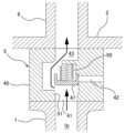
도 3은 잠몰식 펌프(1)가 운전하고 있을 때의 유로 전환 장치(5)의 상태를 나타내고 있다. 잠몰식 펌프(1)가 운전하고 있을 때, 액화 가스는, 잠몰식 펌프(1)의 토출구(1b)로부터 토출되어, 유로 전환 장치(5)의 제1 유로(41)로 유입된다. 제1 유로(41)를 흐르는 액화 가스는, 밸브체(47)를 스프링(50)의 힘에 저항하여 이동시켜, 제1 유로(41)를 개방함과 함께, 제2 유로(42)를 밸브체(47)로 닫는다. 그 결과, 제1 유로(41)와 제3 유로(43)가 연통한다.3 shows the state of the flow
잠몰식 펌프(1)의 운전이 정지되면, 밸브체(47)는 스프링(50)에 의해 밸브 시트(51)에 대하여 압박 접촉된다. 그 결과, 도 2에 나타내는 바와 같이, 제1 유로(41)는 닫히고, 제2 유로(42)와 제3 유로(43)는 연통한다. 이와 같이, 본 실시 형태의 유로 전환 장치(5)는 스프링(50)과 액화 가스의 흐름만에 의해 작동한다. 일 실시 형태에서는, 유로 전환 장치(5)는 밸브체(47)를 이동시키는 액추에이터(예를 들어 전동 액추에이터 또는 유체 액추에이터)를 가져도 된다.When the operation of the
잠몰식 펌프(1)를 운전하기 전, 흡입 용기(2)로부터 공기를 퍼지 가스에 의해 배제하는 드라이업, 및 잠몰식 펌프(1)를 액화 가스로 냉각하는 쿨다운이 행해진다. 드라이업 및 쿨다운은, 도 2에 나타내는 상태, 즉, 제1 유로(41)가 밸브체(47)로 닫히고, 제2 유로(42)와 제3 유로(43)가 연통한 상태에서 행해진다.Before operating the
드라이업은, 상온의 퍼지 가스를 흡입 용기(2)에 도입하여 잠몰식 펌프(1)를 건조시키는 동작이다. 이하, 드라이업의 일 실시 형태에 대하여 도 4를 참조하여 설명한다. 잠몰식 펌프(1)의 운전이 정지되어 있는 상태(즉, 도 2에 나타내는 상태)에서, 퍼지 가스는, 흡입 포트(7)를 통해 흡입 용기(2) 내에 공급된다. 토출 밸브(23) 및 벤트 밸브(32)는 닫혀 있고, 흡입 밸브(22) 및 드레인 밸브(26)는 열려 있다. 벤트 밸브(32)는 열려도 된다. 퍼지 가스는, 흡입 용기(2) 내에 존재하는 공기를 밀어내고, 공기와 함께 드레인 라인(25)을 통해 배출된다. 이윽고 흡입 용기(2)의 내부는 퍼지 가스로 채워지고, 이에 의해 잠몰식 펌프(1)가 건조된다.Dry-up is an operation of drying the
일 실시 형태에서는, 드라이업은 다음과 같이 실시되어도 된다. 도 5에 나타내는 바와 같이, 잠몰식 펌프(1)의 운전이 정지되어 있는 상태(즉, 도 2에 나타내는 상태)에서, 퍼지 가스는, 흡입 포트(7)를 통해 흡입 용기(2) 내에 공급된다. 드레인 밸브(26) 및 벤트 밸브(32)는 닫혀 있고, 흡입 밸브(22) 및 토출 밸브(23)는 열려 있다. 벤트 밸브(32)는 열려도 된다. 퍼지 가스는, 흡입 용기(2) 내에 존재하는 공기를 밀어내고, 공기와 함께 유로 전환 장치(5)의 제2 유로(42)와 제3 유로(43), 및 토출 포트(8)를 통해 배출된다. 이윽고 흡입 용기(2)의 내부는 퍼지 가스로 채워지고, 이에 의해 잠몰식 펌프(1)가 건조된다.In one embodiment, dry-up may be performed as follows. As shown in FIG. 5 , in a state where the operation of the
또한 일 실시 형태에서는, 드라이업은 다음과 같이 실시되어도 된다. 도 6에 나타내는 바와 같이, 잠몰식 펌프(1)의 운전이 정지되어 있는 상태(즉, 도 2에 나타내는 상태)에서, 퍼지 가스는, 드레인 라인(25)을 통해 흡입 용기(2) 내에 공급된다. 흡입 밸브(22) 및 벤트 밸브(32)는 닫혀 있고, 드레인 밸브(26) 및 토출 밸브(23)는 열려 있다. 벤트 밸브(32)는 열려도 된다. 퍼지 가스는, 흡입 용기(2) 내에 존재하는 공기를 밀어내고, 공기와 함께 유로 전환 장치(5)의 제2 유로(42)와 제3 유로(43), 및 토출 포트(8)를 통해 배출된다. 이윽고 흡입 용기(2)의 내부는 퍼지 가스로 채워지고, 이에 의해 잠몰식 펌프(1)가 건조된다.In one embodiment, dry-up may be performed as follows. As shown in FIG. 6 , in a state where the operation of the
도 4 내지 도 6에 나타내는 실시 형태에서는, 제1 유로(41)는 밸브체(47)에 의해 닫혀 있다. 따라서, 흡입 용기(2) 내에 도입된 퍼지 가스는, 잠몰식 펌프(1) 내를 흐르지 않는다. 결과적으로, 잠몰식 펌프(1)의 임펠러(15)의 공전이 방지되어, 베어링(14A, 14B, 14C) 등의 미끄럼 이동부의 손상이 방지된다.In the embodiment shown in FIGS. 4 to 6 , the
드라이업에 사용되는 퍼지 가스는, 액화 가스를 구성하는 원소보다 낮은 비점을 갖는 원소로 이루어지는 불활성 가스이다. 이는, 드라이업 후에 도입되는 극저온의 액화 가스에 퍼지 가스가 접촉했을 때, 퍼지 가스가 액화되는 것 방지하기 위해서이다. 예를 들어, 액화 가스가 액화 천연가스(LNG) 또는 액화 암모니아인 경우, 사용되는 퍼지 가스는 질소 가스이다. 다른 예에서는, 액화 가스가 액체 수소인 경우, 사용되는 퍼지 가스는 헬륨 가스이다.The purge gas used for dry-up is an inert gas composed of an element having a lower boiling point than an element constituting the liquefied gas. This is to prevent the purge gas from being liquefied when the purge gas contacts the cryogenic liquefied gas introduced after dry-up. For example, when the liquefied gas is liquefied natural gas (LNG) or liquefied ammonia, the purge gas used is nitrogen gas. In another example, when the liquefied gas is liquid hydrogen, the purge gas used is helium gas.
쿨다운은, 상기 드라이업 후에, 액화 가스를 흡입 용기(2)에 도입하여 잠몰식 펌프(1)를 냉각하는 동작이다. 이하, 쿨다운의 일 실시 형태에 대하여 도 7을 참조하여 설명한다. 도 7에 나타내는 바와 같이, 잠몰식 펌프(1)의 운전이 정지되어 있는 상태(즉, 도 2에 나타내는 상태)에서, 액화 가스는, 흡입 포트(7)를 통해 흡입 용기(2) 내에 공급된다. 드레인 밸브(26) 및 벤트 밸브(32)는 닫혀 있고, 흡입 밸브(22) 및 토출 밸브(23)는 열려 있다. 벤트 밸브(32)는 열려도 된다. 액화 가스는, 상온의 잠몰식 펌프(1) 및 흡입 용기(2)에 접촉하여 기화되어, 가스를 생성한다(이하, 이것을 생성 가스라고 함). 생성 가스는, 유로 전환 장치(5)의 제2 유로(42)와 제3 유로(43), 및 토출 포트(8)를 통해 배출된다. 잠몰식 펌프(1) 및 흡입 용기(2)의 온도가 저하됨에 따라, 액화 가스의 기화가 일어나지 않게 된다. 이윽고, 흡입 용기(2)의 내부는 액화 가스로 채워지고, 이에 의해 잠몰식 펌프(1)가 냉각된다.The cool-down is an operation of introducing liquefied gas into the
도 7의 실시 형태에서도, 제1 유로(41)는 밸브체(47)에 의해 닫혀 있다. 따라서, 흡입 용기(2) 내의 생성 가스는, 잠몰식 펌프(1) 내를 흐르지 않는다. 결과적으로, 잠몰식 펌프(1)의 임펠러(15)의 공전이 방지되어, 베어링(14A, 14B, 14C) 등의 미끄럼 이동부의 손상이 방지된다.Also in the embodiment of FIG. 7 , the
도 7에 나타내는 바와 같이, 생성 가스는 토출 포트(8) 및 토출관(20)을 통해 배출된다. 통상, 토출 포트(8) 및 토출관(20)은 벤트 라인(31) 및 드레인 라인(25)에 비하여, 큰 구경을 갖고 있다. 따라서, 잠몰식 펌프(1)를 냉각하기 위한 액화 가스를 높은 유량으로 흡입 용기(2) 내에 도입할 수 있다. 결과적으로, 쿨다운을 짧은 시간에 완료시킬 수 있다. 특히, 본 실시 형태에 의하면, 액화 가스를 높은 유량으로 흡입 용기(2) 내에 도입해도, 생성 가스(액화 가스의 기화에 의해 생성된 가스)는 유로 전환 장치(5)에 의해 잠몰식 펌프(1) 내를 흐르지 않으므로, 잠몰식 펌프(1)는 공전하지 않는다.As shown in FIG. 7 , generated gas is discharged through the
일 실시 형태에서는, 흡입 용기(2) 내에서 발생한 생성 가스를, 토출 포트(8) 및 토출관(20)을 통해 가스 처리 장치(도시하지 않음)로 유도해도 된다. 가스 처리 장치는, 액화 가스로부터 기화된 가스(예를 들어 천연가스 또는 수소 가스 또는 암모니아 가스)를 처리하는 장치이다. 가스 처리 장치의 예로서는, 가스 소각 장치(플레어링 장치), 화학적 가스 처리 장치, 가스 흡착 장치 등을 들 수 있다.In one embodiment, the generated gas generated in the
도 8에 나타내는 바와 같이, 복수의 흡입 용기(2)를 직렬로 연결하여, 복수의 잠몰식 펌프(1)를 동시에 냉각하는 것도 가능하다. 구체적으로는, 하나의 잠몰식 펌프(1)를 수용하는 하나의 흡입 용기(2)의 토출 포트(8)를 다른 잠몰식 펌프(1)를 수용하는 다른 흡입 용기(2)의 흡입 포트(7)에 연결한다. 동일한 방식으로 3개 이상의 흡입 용기(2)를 직렬로 연결할 수 있다. 액화 가스는, 복수의 흡입 용기(2) 중 하나의 흡입 포트(7)로부터 도입되고, 각 흡입 용기(2)를 흐르고, 그리고 복수의 흡입 용기(2) 중 다른 하나의 토출 포트(8)로부터 배출된다. 이들 흡입 용기(2)를 흐르는 액화 가스는, 복수의 잠몰식 펌프(1)를 동시에 냉각할 수 있다.As shown in FIG. 8 , it is also possible to simultaneously cool a plurality of
도 9는 유로 전환 장치(5)의 다른 실시 형태를 나타내는 단면도이다. 특별히 설명하지 않는 본 실시 형태의 구성 및 동작은, 도 2 및 도 3을 참조하여 설명한 실시 형태와 동일하므로, 그 중복되는 설명을 생략한다. 도 9에 나타내는 바와 같이, 유로 구조체(45)는 제1 유로(41)와 제3 유로(43)를 연통시키는 바이패스 유로(55)를 구비하고 있다. 바이패스 유로(55)의 단면적은, 제1 유로(41)의 단면적보다 작다. 보다 구체적으로는, 바이패스 유로(55)의 단면적은, 밸브체(47)가 제1 유로(41)를 닫고, 또한 기체(퍼지 가스 또는 생성 가스)가 잠몰식 펌프(1) 및 바이패스 유로(55)를 흐를 때, 잠몰식 펌프(1)의 임펠러(15)가 상기 기체의 흐름에 의해 회전하지 않는 단면적이다.9 is a cross-sectional view showing another embodiment of the flow
바이패스 유로(55)는 도 9에 나타내는 바와 같은 통공(通孔)이어도 되고, 혹은 밸브 시트(51)에 형성된 홈이어도 된다. 상기 기체가 임펠러(15)를 회전시키지 않는 한, 복수의 바이패스 유로(55)가 마련되어도 된다. 본 실시 형태에 의하면, 드라이업 및 쿨다운 시에, 퍼지 가스 또는 액화 가스를 잠몰식 펌프(1)의 내부에 원활하게 도입시킬 수 있다. 결과적으로, 잠몰식 펌프(1)의 드라이업 및 쿨다운을 보다 짧은 시간에 완료할 수 있다.The
도 10에 나타내는 바와 같이, 일 실시 형태에서는, 펌프 시스템은, 잠몰식 펌프(1)의 회전을 검출하는 회전 검출기(60)를 구비해도 된다. 회전 검출기(60)의 구체적 구성은, 잠몰식 펌프(1)의 회전(즉, 회전축(12) 또는 임펠러(15)의 회전)을 검출할 수 있는 것이면, 특별히 한정되지는 않는다. 도 10에 나타내는 예에서는, 회전 검출기(60)는 전동기(11)가 회전하고 있을 때 발생하는 유도 기전력을 검출하는 유도 기전력 검출기이다. 다른 예에서는, 도시하지 않지만, 회전 검출기(60)는 회전축(12) 또는 임펠러(15)의 회전을 직접적으로 검출하는 회전 검출기여도 된다. 회전 검출기(60)로부터의 출력값에 기초하여, 잠몰식 펌프(1)가 회전하지 않는 바이패스 유로(55)의 단면적을 결정할 수 있다.As shown in FIG. 10 , in one embodiment, the pump system may include a
도 11에 나타내는 바와 같이, 일 실시 형태에서는, 펌프 시스템은, 잠몰식 펌프(1)의 회전을 방지하기 위한 회전 방지 장치(70)를 더 구비해도 된다. 회전 방지 장치(70)의 구체적 구성은, 잠몰식 펌프(1)의 회전(즉, 회전축(12) 또는 임펠러(15)의 회전)을 방지할 수 있는 것이면, 특별히 한정되지는 않는다. 예를 들어, 회전 방지 장치(70)는 브레이크 패드를 회전축(12)에 압박 접촉시켜 회전축(12) 및 임펠러(15)의 회전을 방지하는 기계식 회전 방지 장치여도 된다. 브레이크 패드를 구동시키는 액추에이터의 예에는, 유체식 액추에이터(예를 들어 가스 실린더), 전기식 액추에이터(예를 들어 전자 솔레노이드) 등을 들 수 있다. 다른 예에서는, 회전 방지 장치(70)는 코일에 통전함으로써 발생하는 전자력에 의해 회전축(12) 및 임펠러(15)의 회전을 방지하는 전자식 회전 방지 장치여도 된다.As shown in FIG. 11 , in one embodiment, the pump system may further include a
상술한 실시 형태는, 본 발명이 속하는 기술분야에서의 통상의 지식을 가진 자가 본 발명을 실시할 수 있을 것을 목적으로 하여 기재된 것이다. 상기 실시 형태의 다양한 변형예는, 당업자라면 당연히 이룰 수 있는 것이며, 본 발명의 기술적 사상은 다른 실시 형태에도 적용할 수 있다. 따라서, 본 발명은 기재된 실시 형태에 한정되지는 않고, 특허 청구 범위에 의해 정의되는 기술적 사상에 따른 가장 넓은 범위로 해석되는 것이다.The embodiments described above are described for the purpose of being able to implement the present invention by those skilled in the art in the technical field to which the present invention belongs. Various modified examples of the above embodiments can be naturally made by those skilled in the art, and the technical idea of the present invention can be applied to other embodiments as well. Therefore, the present invention is not limited to the described embodiments, but is interpreted in the widest range according to the technical idea defined by the claims.
본 발명은 액화 암모니아, 액체 수소, 액체 질소, 액화 천연가스, 액화 에틸렌 가스, 액화 석유 가스 등의 액화 가스를 이송하는 용도로 사용되는 잠몰식 펌프의 공전을 방지하기 위한 기술에 이용 가능하다.The present invention can be used for a technique for preventing revolution of a submersible pump used for transporting liquefied gases such as liquefied ammonia, liquid hydrogen, liquid nitrogen, liquefied natural gas, liquefied ethylene gas, and liquefied petroleum gas.
1: 잠몰식 펌프
1a: 흡입구
1b: 토출구
2: 흡입 용기
5: 유로 전환 장치
7: 흡입 포트
8: 토출 포트
11: 전동기
12: 회전축
14A, 14B, 14C: 베어링
15: 임펠러
16: 펌프 케이싱
17: 토출 유로
20: 토출관
22: 흡입 밸브
23: 토출 밸브
25: 드레인 라인
26: 드레인 밸브
31: 벤트 라인
32: 벤트 밸브
41: 제1 유로
42: 제2 유로
43: 제3 유로
45: 유로 구조체
47: 밸브체
50: 스프링
51: 밸브 시트
55: 바이패스 유로
60: 회전 검출기
70: 회전 방지 장치1: submersible pump
1a: inlet
1b: discharge port
2: Suction container
5: Euro conversion device
7: suction port
8: discharge port
11: electric motor
12: axis of rotation
14A, 14B, 14C: bearings
15: impeller
16: pump casing
17: discharge flow path
20: discharge pipe
22: intake valve
23: discharge valve
25: drain line
26: drain valve
31: vent line
32: vent valve
41: first euro
42: second euro
43: third euro
45: flow path structure
47: valve body
50: spring
51: valve seat
55: Bypass Euro
60: rotation detector
70: anti-rotation device
Claims (15)
제1 유로, 제2 유로, 및 제3 유로를 갖는 유로 구조체와,
상기 유로 구조체 내에 배치되고, 상기 제3 유로를 상기 제1 유로 또는 상기 제2 유로 중 어느 것에 선택적으로 연통시키는 밸브체를 구비하고 있고,
상기 제1 유로는, 상기 잠몰식 펌프의 토출구에 연통하고,
상기 제2 유로는, 상기 흡입 용기의 내부에 연통하고,
상기 제3 유로는, 상기 흡입 용기의 토출 포트에 연통하는, 유로 전환 장치.It is used to transfer liquefied gas and is also a flow path conversion device for preventing the slippage of the submersible pump disposed in the suction container,
A flow path structure having a first flow path, a second flow path, and a third flow path;
A valve element disposed in the flow path structure and selectively communicating the third flow path with either the first flow path or the second flow path;
The first flow path communicates with the discharge port of the submersible pump,
The second flow path communicates with the inside of the suction container,
The passage switching device according to claim 1, wherein the third passage communicates with the discharge port of the suction container.
상기 유로 구조체는, 상기 제1 유로와 상기 제3 유로를 연통시키는 바이패스 유로를 더 구비하고 있고, 상기 바이패스 유로의 단면적은, 상기 제1 유로의 단면적보다 작은, 유로 전환 장치.According to claim 1,
The flow path structure further includes a bypass flow path that communicates the first flow path and the third flow path, and a cross-sectional area of the bypass flow path is smaller than a cross-sectional area of the first flow path.
상기 바이패스 유로의 단면적은, 상기 밸브체가 상기 제1 유로를 닫고, 또한 기체가 상기 잠몰식 펌프 및 상기 바이패스 유로를 흐를 때, 상기 잠몰식 펌프의 임펠러가 상기 기체의 흐름에 의해 회전하지 않는 단면적인, 유로 전환 장치.According to claim 2,
The cross-sectional area of the bypass passage is such that when the valve body closes the first passage and gas flows through the submersible pump and the bypass passage, the impeller of the submersible pump does not rotate due to the flow of the gas. Cross-section, Euro-diverting device.
상기 밸브체를 상기 유로 구조체에 대하여 압박 접촉시켜 상기 제1 유로를 닫는 스프링을 더 구비하고 있는, 유로 전환 장치.According to any one of claims 1 to 3,
The flow path switching device further includes a spring for pressing the valve element into contact with the flow path structure to close the first flow path.
상기 잠몰식 펌프가 내부에 수용된 흡입 용기와,
상기 잠몰식 펌프의 공전을 방지하기 위한, 제1항 내지 제4항 중 어느 한 항에 기재된 유로 전환 장치를 구비하고 있는, 펌프 시스템.A submersible pump for transporting liquefied gas;
A suction container in which the submersible pump is accommodated;
A pump system comprising the flow path switching device according to any one of claims 1 to 4 for preventing revolution of the submersible pump.
상기 잠몰식 펌프의 회전을 검출하는 회전 검출기를 더 구비하고 있는, 펌프 시스템.According to claim 5,
The pump system further comprising a rotation detector for detecting rotation of the submersible pump.
상기 잠몰식 펌프의 회전을 방지하는 회전 방지 장치를 더 구비하고 있는, 펌프 시스템.According to claim 5,
Further comprising an anti-rotation device for preventing rotation of the submersible pump, the pump system.
상기 잠몰식 펌프의 토출구에 연통하는 제1 유로를 밸브체로 닫고, 또한 상기 흡입 용기의 내부에 연통하는 제2 유로와, 상기 흡입 용기의 토출 포트에 연통하는 제3 유로가 연통한 상태에서, 액화 가스를 상기 흡입 용기 내에 공급하고,
상기 흡입 용기 내에서 발생한 가스를 상기 제2 유로 및 상기 제3 유로를 통해 상기 토출 포트에 이송하는, 방법.A method for preventing slipping of a submersible pump used for transporting liquefied gas and also disposed in a suction vessel,
Liquefied in a state where the first flow path communicating with the discharge port of the submersible pump is closed with a valve body, and the second flow path communicating with the inside of the suction container is in communication with the third flow path communicating with the discharge port of the suction container. supplying a gas into the inhalation vessel;
and transferring gas generated in the suction container to the discharge port through the second flow path and the third flow path.
상기 액화 가스를 상기 흡입 용기 내에 공급하기 전에, 퍼지 가스를 상기 흡입 용기 내에 공급하는 공정을 더 포함하는, 방법.According to claim 8,
The method further includes a step of supplying a purge gas into the suction container before supplying the liquefied gas into the suction container.
상기 퍼지 가스는, 상기 흡입 용기의 흡입 포트를 통해 상기 흡입 용기 내에 공급되고, 상기 흡입 용기의 저부에 접속된 드레인 라인을 통해 배출되고, 상기 흡입 포트는 상기 흡입 용기의 저부보다 높은 위치에 있는, 방법.According to claim 9,
the purge gas is supplied into the suction container through a suction port of the suction container and discharged through a drain line connected to a bottom of the suction container, the suction port being higher than the bottom of the suction container; method.
상기 퍼지 가스는, 상기 흡입 용기의 흡입 포트를 통해 상기 흡입 용기 내에 공급되고, 상기 제2 유로, 상기 제3 유로, 및 상기 토출 포트를 통해 배출되는, 방법.According to claim 9,
wherein the purge gas is supplied into the suction vessel through a suction port of the suction vessel and discharged through the second flow path, the third flow path, and the discharge port.
상기 퍼지 가스는, 상기 흡입 용기의 저부에 접속된 드레인 라인을 통해 상기 흡입 용기 내에 공급되고, 상기 제2 유로, 상기 제3 유로, 및 상기 토출 포트를 통해 배출되는, 방법.According to claim 9,
wherein the purge gas is supplied into the suction vessel through a drain line connected to a bottom of the suction vessel, and discharged through the second flow path, the third flow path, and the discharge port.
상기 퍼지 가스는, 상기 액화 가스를 구성하는 원소보다 낮은 비점을 갖는 원소로 이루어지는 불활성 가스인, 방법.According to any one of claims 9 to 12,
The method of claim 1 , wherein the purge gas is an inert gas composed of an element having a lower boiling point than an element constituting the liquefied gas.
상기 제2 유로를 상기 밸브체로 닫고, 또한 상기 제1 유로와 상기 제3 유로가 연통한 상태에서, 상기 잠몰식 펌프를 운전하는 공정을 더 포함하는, 방법.According to any one of claims 8 to 13,
The method further includes a step of closing the second flow path with the valve body and operating the submersible pump in a state where the first flow path and the third flow path communicate with each other.
상기 흡입 용기 내에서 발생한 가스를, 상기 토출 포트를 통해 가스 처리 장치로 유도하는 공정을 더 포함하는, 방법.The method of any one of claims 8 to 14,
The method further includes a step of guiding gas generated in the suction container to a gas processing device through the discharge port.
Applications Claiming Priority (3)
| Application Number | Priority Date | Filing Date | Title |
|---|---|---|---|
| JPJP-P-2020-196643 | 2020-11-27 | ||
| JP2020196643 | 2020-11-27 | ||
| PCT/JP2021/031502 WO2022113450A1 (en) | 2020-11-27 | 2021-08-27 | Flow path switching device and method for preventing dry running of submerged-type pump |
Publications (1)
| Publication Number | Publication Date |
|---|---|
| KR20230107360A true KR20230107360A (en) | 2023-07-14 |
Family
ID=81754502
Family Applications (1)
| Application Number | Title | Priority Date | Filing Date |
|---|---|---|---|
| KR1020237021032A KR20230107360A (en) | 2020-11-27 | 2021-08-27 | How to prevent slipping in diverters and submersible pumps |
Country Status (8)
| Country | Link |
|---|---|
| US (1) | US20240011492A1 (en) |
| EP (1) | EP4253759A1 (en) |
| JP (1) | JPWO2022113450A1 (en) |
| KR (1) | KR20230107360A (en) |
| CN (1) | CN116529489A (en) |
| AU (1) | AU2021386726A1 (en) |
| CA (1) | CA3202585A1 (en) |
| WO (1) | WO2022113450A1 (en) |
Families Citing this family (3)
| Publication number | Priority date | Publication date | Assignee | Title |
|---|---|---|---|---|
| JP2023173562A (en) * | 2022-05-26 | 2023-12-07 | 株式会社荏原製作所 | Method for starting and stopping pump devices connected in series |
| WO2023228995A1 (en) * | 2022-05-26 | 2023-11-30 | 株式会社荏原製作所 | Dry-up method, cool-down method, and heat-up method for pump device |
| CN117783454B (en) * | 2024-02-28 | 2024-04-23 | 陕西省环境监测中心站 | Pollution source organic gas detection device for real-time quantitative detection |
Citations (1)
| Publication number | Priority date | Publication date | Assignee | Title |
|---|---|---|---|---|
| JPS59159795A (en) | 1983-03-04 | 1984-09-10 | Yakult Honsha Co Ltd | Production of clathrated ursodeoxychloic acid by microbial conversion |
Family Cites Families (7)
| Publication number | Priority date | Publication date | Assignee | Title |
|---|---|---|---|---|
| JPS582497A (en) * | 1981-06-29 | 1983-01-08 | Nikkiso Co Ltd | Automatic gas drainage unit for pit barrel type pump |
| JPS59159795U (en) | 1983-04-12 | 1984-10-26 | 株式会社荏原製作所 | submerged motor pump |
| JPS61162579U (en) * | 1985-03-29 | 1986-10-08 | ||
| JPS6231680U (en) | 1985-08-09 | 1987-02-25 | ||
| JPH06307376A (en) * | 1993-04-22 | 1994-11-01 | Hitachi Ltd | Submerged pump device for liquefied gas tank |
| JP4300088B2 (en) * | 2003-09-29 | 2009-07-22 | 日機装株式会社 | Submerged pump |
| JP2007024166A (en) * | 2005-07-15 | 2007-02-01 | Taiyo Nippon Sanso Corp | Low-temperature liquefied gas supply device |
-
2021
- 2021-08-27 AU AU2021386726A patent/AU2021386726A1/en active Pending
- 2021-08-27 CA CA3202585A patent/CA3202585A1/en active Pending
- 2021-08-27 EP EP21897428.5A patent/EP4253759A1/en active Pending
- 2021-08-27 KR KR1020237021032A patent/KR20230107360A/en unknown
- 2021-08-27 US US18/253,610 patent/US20240011492A1/en active Pending
- 2021-08-27 CN CN202180078479.9A patent/CN116529489A/en active Pending
- 2021-08-27 WO PCT/JP2021/031502 patent/WO2022113450A1/en active Application Filing
- 2021-08-27 JP JP2022565060A patent/JPWO2022113450A1/ja active Pending
Patent Citations (1)
| Publication number | Priority date | Publication date | Assignee | Title |
|---|---|---|---|---|
| JPS59159795A (en) | 1983-03-04 | 1984-09-10 | Yakult Honsha Co Ltd | Production of clathrated ursodeoxychloic acid by microbial conversion |
Also Published As
| Publication number | Publication date |
|---|---|
| WO2022113450A1 (en) | 2022-06-02 |
| EP4253759A1 (en) | 2023-10-04 |
| US20240011492A1 (en) | 2024-01-11 |
| CN116529489A (en) | 2023-08-01 |
| AU2021386726A9 (en) | 2024-05-02 |
| AU2021386726A1 (en) | 2023-06-29 |
| JPWO2022113450A1 (en) | 2022-06-02 |
| CA3202585A1 (en) | 2022-06-02 |
Similar Documents
| Publication | Publication Date | Title |
|---|---|---|
| KR20230107360A (en) | How to prevent slipping in diverters and submersible pumps | |
| EP2683944B1 (en) | Subsea motor-turbomachine | |
| JP5753952B2 (en) | Hydrate pellet storage, transport and dissociation container and hydrate pellet storage, transport and dissociation method using the same | |
| JP4570130B2 (en) | Equipment-linked low temperature liquefied gas supply equipment | |
| MXPA02003337A (en) | Pumping system and method for pumping fluids. | |
| US11549516B2 (en) | Sealing system, and pump system including the sealing system | |
| CN111613814A (en) | Fuel cell system and hydrogen circulation pump | |
| JP3514855B2 (en) | Pump for low temperature liquefied gas | |
| WO2023228995A1 (en) | Dry-up method, cool-down method, and heat-up method for pump device | |
| JPWO2007040033A1 (en) | Cooling system, operating method thereof, and plasma processing system using the cooling system | |
| JP2022166087A (en) | Evaporated gas compressor for lng propulsion vessel | |
| WO2023228792A1 (en) | Start-up method and stopping method for pump devices connected in series | |
| US8253292B2 (en) | Cryogenic submerged turbine generator with hydrostatic bearings | |
| JP5142748B2 (en) | Multistage pump, cryogenic liquid storage equipment, cryogenic liquid transfer equipment | |
| KR102426720B1 (en) | Cryogenic liquid pump using pneumatic motor and transfer method of cryogenic liquid using the same | |
| JP2009191730A5 (en) | ||
| WO2023182367A1 (en) | Cooling-down method for liquefied gas storage tank | |
| JP3340852B2 (en) | Liquid pump | |
| KR102195464B1 (en) | Superconducting Motor Application Piping Integrated Cryogenic Refrigerant Pump | |
| JP2024041519A (en) | Fluid circulation pumps and fluid transfer devices | |
| EP4222366A1 (en) | Gas supply system for high- and low-pressure gas consuming appliances | |
| JP2023140782A (en) | Cooling down method of liquefied gas storage tank | |
| JPH11230079A (en) | Submerged pump | |
| FR3114797A1 (en) | Gas supply system for appliances using high and low pressure gas | |
| TW202411538A (en) | Pump device, pump system, and method of operating pump system |