KR20230097097A - Filter pleat pack and air filter unit - Google Patents
Filter pleat pack and air filter unit Download PDFInfo
- Publication number
- KR20230097097A KR20230097097A KR1020237017664A KR20237017664A KR20230097097A KR 20230097097 A KR20230097097 A KR 20230097097A KR 1020237017664 A KR1020237017664 A KR 1020237017664A KR 20237017664 A KR20237017664 A KR 20237017664A KR 20230097097 A KR20230097097 A KR 20230097097A
- Authority
- KR
- South Korea
- Prior art keywords
- filter
- air
- pleat pack
- support layer
- band
- Prior art date
Links
- 230000035699 permeability Effects 0.000 claims abstract description 73
- 238000009423 ventilation Methods 0.000 claims abstract description 61
- 230000000903 blocking effect Effects 0.000 claims abstract description 48
- 239000012528 membrane Substances 0.000 claims abstract description 35
- 239000011347 resin Substances 0.000 claims description 119
- 229920005989 resin Polymers 0.000 claims description 119
- 239000000463 material Substances 0.000 claims description 109
- 238000000034 method Methods 0.000 claims description 54
- 210000000988 bone and bone Anatomy 0.000 claims description 30
- 238000011144 upstream manufacturing Methods 0.000 claims description 30
- 229920001343 polytetrafluoroethylene Polymers 0.000 claims description 18
- 239000004810 polytetrafluoroethylene Substances 0.000 claims description 18
- 230000002401 inhibitory effect Effects 0.000 claims description 14
- 239000011324 bead Substances 0.000 claims description 11
- 239000012943 hotmelt Substances 0.000 claims description 11
- 239000012466 permeate Substances 0.000 claims description 7
- -1 polytetrafluoroethylene Polymers 0.000 claims description 5
- 238000007789 sealing Methods 0.000 claims description 5
- 230000007423 decrease Effects 0.000 abstract description 6
- 239000010410 layer Substances 0.000 description 150
- 239000002245 particle Substances 0.000 description 51
- 239000000835 fiber Substances 0.000 description 22
- 239000004744 fabric Substances 0.000 description 20
- 229920013639 polyalphaolefin Polymers 0.000 description 15
- 238000004519 manufacturing process Methods 0.000 description 14
- 239000011248 coating agent Substances 0.000 description 10
- 238000000576 coating method Methods 0.000 description 10
- 238000010586 diagram Methods 0.000 description 8
- 239000004698 Polyethylene Substances 0.000 description 7
- 230000000052 comparative effect Effects 0.000 description 7
- 229920000573 polyethylene Polymers 0.000 description 7
- 230000015572 biosynthetic process Effects 0.000 description 6
- 239000002131 composite material Substances 0.000 description 6
- 239000002657 fibrous material Substances 0.000 description 6
- 239000010687 lubricating oil Substances 0.000 description 6
- 239000004745 nonwoven fabric Substances 0.000 description 6
- 229920000139 polyethylene terephthalate Polymers 0.000 description 6
- 239000005020 polyethylene terephthalate Substances 0.000 description 6
- 239000003566 sealing material Substances 0.000 description 6
- 238000005304 joining Methods 0.000 description 5
- 239000005038 ethylene vinyl acetate Substances 0.000 description 4
- 239000012530 fluid Substances 0.000 description 4
- 238000007499 fusion processing Methods 0.000 description 4
- 229920001200 poly(ethylene-vinyl acetate) Polymers 0.000 description 4
- 238000012545 processing Methods 0.000 description 4
- 239000000565 sealant Substances 0.000 description 4
- 229920009638 Tetrafluoroethylene-Hexafluoropropylene-Vinylidenefluoride Copolymer Polymers 0.000 description 3
- 239000000853 adhesive Substances 0.000 description 3
- 230000001070 adhesive effect Effects 0.000 description 3
- 229920001577 copolymer Polymers 0.000 description 3
- 238000011156 evaluation Methods 0.000 description 3
- 238000011049 filling Methods 0.000 description 3
- 239000002184 metal Substances 0.000 description 3
- 229910052751 metal Inorganic materials 0.000 description 3
- 239000000203 mixture Substances 0.000 description 3
- 230000035515 penetration Effects 0.000 description 3
- 239000000843 powder Substances 0.000 description 3
- 238000005096 rolling process Methods 0.000 description 3
- 238000012360 testing method Methods 0.000 description 3
- 238000009823 thermal lamination Methods 0.000 description 3
- YCKRFDGAMUMZLT-UHFFFAOYSA-N Fluorine atom Chemical compound [F] YCKRFDGAMUMZLT-UHFFFAOYSA-N 0.000 description 2
- 239000004743 Polypropylene Substances 0.000 description 2
- 239000004372 Polyvinyl alcohol Substances 0.000 description 2
- 239000011230 binding agent Substances 0.000 description 2
- 238000001816 cooling Methods 0.000 description 2
- SNRUBQQJIBEYMU-UHFFFAOYSA-N dodecane Chemical compound CCCCCCCCCCCC SNRUBQQJIBEYMU-UHFFFAOYSA-N 0.000 description 2
- 229920001971 elastomer Polymers 0.000 description 2
- 229920000840 ethylene tetrafluoroethylene copolymer Polymers 0.000 description 2
- 238000001914 filtration Methods 0.000 description 2
- 229910052731 fluorine Inorganic materials 0.000 description 2
- 239000011737 fluorine Substances 0.000 description 2
- 238000005259 measurement Methods 0.000 description 2
- 238000002844 melting Methods 0.000 description 2
- 230000008018 melting Effects 0.000 description 2
- 239000003921 oil Substances 0.000 description 2
- 229920002647 polyamide Polymers 0.000 description 2
- 229920001155 polypropylene Polymers 0.000 description 2
- 229920002451 polyvinyl alcohol Polymers 0.000 description 2
- 238000011045 prefiltration Methods 0.000 description 2
- 239000005060 rubber Substances 0.000 description 2
- 238000000926 separation method Methods 0.000 description 2
- 239000002356 single layer Substances 0.000 description 2
- 229920002972 Acrylic fiber Polymers 0.000 description 1
- 239000004925 Acrylic resin Substances 0.000 description 1
- 229920000178 Acrylic resin Polymers 0.000 description 1
- NLHHRLWOUZZQLW-UHFFFAOYSA-N Acrylonitrile Chemical compound C=CC#N NLHHRLWOUZZQLW-UHFFFAOYSA-N 0.000 description 1
- 239000004215 Carbon black (E152) Substances 0.000 description 1
- 229920003171 Poly (ethylene oxide) Polymers 0.000 description 1
- 239000004952 Polyamide Substances 0.000 description 1
- 229920006361 Polyflon Polymers 0.000 description 1
- 230000001154 acute effect Effects 0.000 description 1
- 239000000443 aerosol Substances 0.000 description 1
- 239000004760 aramid Substances 0.000 description 1
- 229920003235 aromatic polyamide Polymers 0.000 description 1
- 238000005452 bending Methods 0.000 description 1
- 230000003111 delayed effect Effects 0.000 description 1
- 239000000428 dust Substances 0.000 description 1
- 238000001125 extrusion Methods 0.000 description 1
- 239000000945 filler Substances 0.000 description 1
- 230000004927 fusion Effects 0.000 description 1
- 239000003365 glass fiber Substances 0.000 description 1
- 238000010438 heat treatment Methods 0.000 description 1
- 229930195733 hydrocarbon Natural products 0.000 description 1
- 150000002430 hydrocarbons Chemical class 0.000 description 1
- 230000008595 infiltration Effects 0.000 description 1
- 238000001764 infiltration Methods 0.000 description 1
- 238000003475 lamination Methods 0.000 description 1
- 229940057995 liquid paraffin Drugs 0.000 description 1
- 238000000691 measurement method Methods 0.000 description 1
- 239000004750 melt-blown nonwoven Substances 0.000 description 1
- 150000002739 metals Chemical class 0.000 description 1
- 230000000149 penetrating effect Effects 0.000 description 1
- 229920011301 perfluoro alkoxyl alkane Polymers 0.000 description 1
- 229920013653 perfluoroalkoxyethylene Polymers 0.000 description 1
- 229920003207 poly(ethylene-2,6-naphthalate) Polymers 0.000 description 1
- 229920000728 polyester Polymers 0.000 description 1
- 239000011112 polyethylene naphthalate Substances 0.000 description 1
- 229920000098 polyolefin Polymers 0.000 description 1
- 229920005672 polyolefin resin Polymers 0.000 description 1
- 238000002360 preparation method Methods 0.000 description 1
- 239000000523 sample Substances 0.000 description 1
- 238000010998 test method Methods 0.000 description 1
- 229920002554 vinyl polymer Polymers 0.000 description 1
Images


Classifications
-
- B—PERFORMING OPERATIONS; TRANSPORTING
- B01—PHYSICAL OR CHEMICAL PROCESSES OR APPARATUS IN GENERAL
- B01D—SEPARATION
- B01D46/00—Filters or filtering processes specially modified for separating dispersed particles from gases or vapours
- B01D46/52—Particle separators, e.g. dust precipitators, using filters embodying folded corrugated or wound sheet material
- B01D46/521—Particle separators, e.g. dust precipitators, using filters embodying folded corrugated or wound sheet material using folded, pleated material
-
- B—PERFORMING OPERATIONS; TRANSPORTING
- B01—PHYSICAL OR CHEMICAL PROCESSES OR APPARATUS IN GENERAL
- B01D—SEPARATION
- B01D63/00—Apparatus in general for separation processes using semi-permeable membranes
- B01D63/02—Hollow fibre modules
- B01D63/021—Manufacturing thereof
- B01D63/0231—Manufacturing thereof using supporting structures, e.g. filaments for weaving mats
-
- B—PERFORMING OPERATIONS; TRANSPORTING
- B01—PHYSICAL OR CHEMICAL PROCESSES OR APPARATUS IN GENERAL
- B01D—SEPARATION
- B01D39/00—Filtering material for liquid or gaseous fluids
- B01D39/08—Filter cloth, i.e. woven, knitted or interlaced material
- B01D39/086—Filter cloth, i.e. woven, knitted or interlaced material of inorganic material
-
- B—PERFORMING OPERATIONS; TRANSPORTING
- B01—PHYSICAL OR CHEMICAL PROCESSES OR APPARATUS IN GENERAL
- B01D—SEPARATION
- B01D39/00—Filtering material for liquid or gaseous fluids
- B01D39/14—Other self-supporting filtering material ; Other filtering material
- B01D39/16—Other self-supporting filtering material ; Other filtering material of organic material, e.g. synthetic fibres
- B01D39/1607—Other self-supporting filtering material ; Other filtering material of organic material, e.g. synthetic fibres the material being fibrous
- B01D39/1623—Other self-supporting filtering material ; Other filtering material of organic material, e.g. synthetic fibres the material being fibrous of synthetic origin
- B01D39/163—Other self-supporting filtering material ; Other filtering material of organic material, e.g. synthetic fibres the material being fibrous of synthetic origin sintered or bonded
-
- B—PERFORMING OPERATIONS; TRANSPORTING
- B01—PHYSICAL OR CHEMICAL PROCESSES OR APPARATUS IN GENERAL
- B01D—SEPARATION
- B01D39/00—Filtering material for liquid or gaseous fluids
- B01D39/14—Other self-supporting filtering material ; Other filtering material
- B01D39/16—Other self-supporting filtering material ; Other filtering material of organic material, e.g. synthetic fibres
- B01D39/1692—Other shaped material, e.g. perforated or porous sheets
-
- B—PERFORMING OPERATIONS; TRANSPORTING
- B01—PHYSICAL OR CHEMICAL PROCESSES OR APPARATUS IN GENERAL
- B01D—SEPARATION
- B01D39/00—Filtering material for liquid or gaseous fluids
- B01D39/14—Other self-supporting filtering material ; Other filtering material
- B01D39/20—Other self-supporting filtering material ; Other filtering material of inorganic material, e.g. asbestos paper, metallic filtering material of non-woven wires
- B01D39/2003—Glass or glassy material
- B01D39/2017—Glass or glassy material the material being filamentary or fibrous
-
- B—PERFORMING OPERATIONS; TRANSPORTING
- B01—PHYSICAL OR CHEMICAL PROCESSES OR APPARATUS IN GENERAL
- B01D—SEPARATION
- B01D39/00—Filtering material for liquid or gaseous fluids
- B01D39/14—Other self-supporting filtering material ; Other filtering material
- B01D39/20—Other self-supporting filtering material ; Other filtering material of inorganic material, e.g. asbestos paper, metallic filtering material of non-woven wires
- B01D39/2027—Metallic material
- B01D39/2041—Metallic material the material being filamentary or fibrous
-
- B—PERFORMING OPERATIONS; TRANSPORTING
- B01—PHYSICAL OR CHEMICAL PROCESSES OR APPARATUS IN GENERAL
- B01D—SEPARATION
- B01D46/00—Filters or filtering processes specially modified for separating dispersed particles from gases or vapours
- B01D46/0002—Casings; Housings; Frame constructions
-
- B—PERFORMING OPERATIONS; TRANSPORTING
- B01—PHYSICAL OR CHEMICAL PROCESSES OR APPARATUS IN GENERAL
- B01D—SEPARATION
- B01D46/00—Filters or filtering processes specially modified for separating dispersed particles from gases or vapours
- B01D46/52—Particle separators, e.g. dust precipitators, using filters embodying folded corrugated or wound sheet material
-
- B—PERFORMING OPERATIONS; TRANSPORTING
- B01—PHYSICAL OR CHEMICAL PROCESSES OR APPARATUS IN GENERAL
- B01D—SEPARATION
- B01D46/00—Filters or filtering processes specially modified for separating dispersed particles from gases or vapours
- B01D46/54—Particle separators, e.g. dust precipitators, using ultra-fine filter sheets or diaphragms
- B01D46/543—Particle separators, e.g. dust precipitators, using ultra-fine filter sheets or diaphragms using membranes
-
- B—PERFORMING OPERATIONS; TRANSPORTING
- B01—PHYSICAL OR CHEMICAL PROCESSES OR APPARATUS IN GENERAL
- B01D—SEPARATION
- B01D63/00—Apparatus in general for separation processes using semi-permeable membranes
- B01D63/14—Pleat-type membrane modules
-
- B—PERFORMING OPERATIONS; TRANSPORTING
- B01—PHYSICAL OR CHEMICAL PROCESSES OR APPARATUS IN GENERAL
- B01D—SEPARATION
- B01D69/00—Semi-permeable membranes for separation processes or apparatus characterised by their form, structure or properties; Manufacturing processes specially adapted therefor
- B01D69/10—Supported membranes; Membrane supports
-
- B—PERFORMING OPERATIONS; TRANSPORTING
- B01—PHYSICAL OR CHEMICAL PROCESSES OR APPARATUS IN GENERAL
- B01D—SEPARATION
- B01D69/00—Semi-permeable membranes for separation processes or apparatus characterised by their form, structure or properties; Manufacturing processes specially adapted therefor
- B01D69/12—Composite membranes; Ultra-thin membranes
- B01D69/1213—Laminated layers
-
- B—PERFORMING OPERATIONS; TRANSPORTING
- B01—PHYSICAL OR CHEMICAL PROCESSES OR APPARATUS IN GENERAL
- B01D—SEPARATION
- B01D69/00—Semi-permeable membranes for separation processes or apparatus characterised by their form, structure or properties; Manufacturing processes specially adapted therefor
- B01D69/12—Composite membranes; Ultra-thin membranes
- B01D69/1216—Three or more layers
-
- B—PERFORMING OPERATIONS; TRANSPORTING
- B01—PHYSICAL OR CHEMICAL PROCESSES OR APPARATUS IN GENERAL
- B01D—SEPARATION
- B01D71/00—Semi-permeable membranes for separation processes or apparatus characterised by the material; Manufacturing processes specially adapted therefor
- B01D71/06—Organic material
- B01D71/30—Polyalkenyl halides
- B01D71/32—Polyalkenyl halides containing fluorine atoms
- B01D71/36—Polytetrafluoroethene
-
- A—HUMAN NECESSITIES
- A62—LIFE-SAVING; FIRE-FIGHTING
- A62B—DEVICES, APPARATUS OR METHODS FOR LIFE-SAVING
- A62B23/00—Filters for breathing-protection purposes
-
- B—PERFORMING OPERATIONS; TRANSPORTING
- B01—PHYSICAL OR CHEMICAL PROCESSES OR APPARATUS IN GENERAL
- B01D—SEPARATION
- B01D2239/00—Aspects relating to filtering material for liquid or gaseous fluids
- B01D2239/02—Types of fibres, filaments or particles, self-supporting or supported materials
- B01D2239/0216—Bicomponent or multicomponent fibres
- B01D2239/0233—Island-in-sea
-
- B—PERFORMING OPERATIONS; TRANSPORTING
- B01—PHYSICAL OR CHEMICAL PROCESSES OR APPARATUS IN GENERAL
- B01D—SEPARATION
- B01D2239/00—Aspects relating to filtering material for liquid or gaseous fluids
- B01D2239/06—Filter cloth, e.g. knitted, woven non-woven; self-supported material
- B01D2239/0604—Arrangement of the fibres in the filtering material
- B01D2239/0622—Melt-blown
-
- B—PERFORMING OPERATIONS; TRANSPORTING
- B01—PHYSICAL OR CHEMICAL PROCESSES OR APPARATUS IN GENERAL
- B01D—SEPARATION
- B01D2239/00—Aspects relating to filtering material for liquid or gaseous fluids
- B01D2239/06—Filter cloth, e.g. knitted, woven non-woven; self-supported material
- B01D2239/0604—Arrangement of the fibres in the filtering material
- B01D2239/0627—Spun-bonded
-
- B—PERFORMING OPERATIONS; TRANSPORTING
- B01—PHYSICAL OR CHEMICAL PROCESSES OR APPARATUS IN GENERAL
- B01D—SEPARATION
- B01D2239/00—Aspects relating to filtering material for liquid or gaseous fluids
- B01D2239/06—Filter cloth, e.g. knitted, woven non-woven; self-supported material
- B01D2239/065—More than one layer present in the filtering material
- B01D2239/0654—Support layers
-
- B—PERFORMING OPERATIONS; TRANSPORTING
- B01—PHYSICAL OR CHEMICAL PROCESSES OR APPARATUS IN GENERAL
- B01D—SEPARATION
- B01D2239/00—Aspects relating to filtering material for liquid or gaseous fluids
- B01D2239/06—Filter cloth, e.g. knitted, woven non-woven; self-supported material
- B01D2239/065—More than one layer present in the filtering material
- B01D2239/0668—The layers being joined by heat or melt-bonding
-
- B—PERFORMING OPERATIONS; TRANSPORTING
- B01—PHYSICAL OR CHEMICAL PROCESSES OR APPARATUS IN GENERAL
- B01D—SEPARATION
- B01D2239/00—Aspects relating to filtering material for liquid or gaseous fluids
- B01D2239/06—Filter cloth, e.g. knitted, woven non-woven; self-supported material
- B01D2239/065—More than one layer present in the filtering material
- B01D2239/0681—The layers being joined by gluing
-
- B—PERFORMING OPERATIONS; TRANSPORTING
- B01—PHYSICAL OR CHEMICAL PROCESSES OR APPARATUS IN GENERAL
- B01D—SEPARATION
- B01D2239/00—Aspects relating to filtering material for liquid or gaseous fluids
- B01D2239/06—Filter cloth, e.g. knitted, woven non-woven; self-supported material
- B01D2239/069—Special geometry of layers
-
- B—PERFORMING OPERATIONS; TRANSPORTING
- B01—PHYSICAL OR CHEMICAL PROCESSES OR APPARATUS IN GENERAL
- B01D—SEPARATION
- B01D2239/00—Aspects relating to filtering material for liquid or gaseous fluids
- B01D2239/08—Special characteristics of binders
- B01D2239/086—Binders between particles or fibres
-
- B—PERFORMING OPERATIONS; TRANSPORTING
- B01—PHYSICAL OR CHEMICAL PROCESSES OR APPARATUS IN GENERAL
- B01D—SEPARATION
- B01D2239/00—Aspects relating to filtering material for liquid or gaseous fluids
- B01D2239/12—Special parameters characterising the filtering material
- B01D2239/1208—Porosity
-
- B—PERFORMING OPERATIONS; TRANSPORTING
- B01—PHYSICAL OR CHEMICAL PROCESSES OR APPARATUS IN GENERAL
- B01D—SEPARATION
- B01D2239/00—Aspects relating to filtering material for liquid or gaseous fluids
- B01D2239/12—Special parameters characterising the filtering material
- B01D2239/1258—Permeability
-
- B—PERFORMING OPERATIONS; TRANSPORTING
- B01—PHYSICAL OR CHEMICAL PROCESSES OR APPARATUS IN GENERAL
- B01D—SEPARATION
- B01D2239/00—Aspects relating to filtering material for liquid or gaseous fluids
- B01D2239/12—Special parameters characterising the filtering material
- B01D2239/1291—Other parameters
-
- B—PERFORMING OPERATIONS; TRANSPORTING
- B01—PHYSICAL OR CHEMICAL PROCESSES OR APPARATUS IN GENERAL
- B01D—SEPARATION
- B01D46/00—Filters or filtering processes specially modified for separating dispersed particles from gases or vapours
- B01D46/52—Particle separators, e.g. dust precipitators, using filters embodying folded corrugated or wound sheet material
- B01D46/521—Particle separators, e.g. dust precipitators, using filters embodying folded corrugated or wound sheet material using folded, pleated material
- B01D46/523—Particle separators, e.g. dust precipitators, using filters embodying folded corrugated or wound sheet material using folded, pleated material with means for maintaining spacing between the pleats or folds
Abstract
제공되는 필터 플리트 팩은, 제1 불소 수지 다공질막과 제1 통기성 지지층을 구비하는 에어 필터 여과재를 포함한다. 제1 통기성 지지층은, 제1 불소 수지 다공질막에 대하여 여과재를 투과하는 기류의 하류측에 배치되며, 또한 폭 방향의 적어도 한쪽의 단부에, 당해 단부를 따라 연장됨과 함께, 제1 통기성 지지층에서의 폭 방향의 통기를 저해하는 통기 저해부를 갖는다. 통기 저해부는, 제1 불소 수지 다공질막에 접하고 있다. 이 필터 플리트 팩은, 플리트 팩의 측면과 프레임체 사이의 간극을 시일함에 있어서, 간극을 하류측으로부터만 덮는 간략화한 시일을 적용한 경우에 있어서도, 에어 필터 유닛의 포집 효율의 저하를 억제하는 데 적합하다.The filter pleat pack provided includes an air filter filter medium including a first porous fluororesin film and a first air permeable support layer. The first air permeability support layer is disposed on the downstream side of the air flow passing through the filter medium with respect to the first fluororesin porous membrane, and extends along at least one end in the width direction along the end, and in the first air permeability support layer. It has a ventilation blocking portion that inhibits ventilation in the width direction. The ventilation blocking portion is in contact with the first porous fluororesin film. This filter pleat pack is suitable for suppressing a decrease in the collection efficiency of the air filter unit even when a simplified seal covering the gap only from the downstream side is applied to seal the gap between the side surface of the pleat pack and the frame body. do.
Description
본 발명은, 불소 수지 다공질막을 구비하는 에어 필터 여과재를 구비한 필터 플리트 팩 및 에어 필터 유닛에 관한 것이다.The present invention relates to a filter pleat pack and an air filter unit provided with an air filter material including a porous fluororesin membrane.
불소 수지 다공질막을 구비하는 에어 필터 여과재는, 진개 등의 입자의 포집 성능이 우수하다. 에어 필터 여과재를 프레임체에 넣어서 에어 필터 유닛으로 하면, 취급성 및 교환성 등을 향상시킬 수 있다. 그 때, 에어 필터 여과재를 플리트상으로 접어서 필터 플리트 팩으로 함으로써, 에어 필터 유닛의 통기 면적(프레임체의 개구 면적)에 대한 여과 면적을 향상시킬 수 있다. 특허문헌 1에는, 필터 플리트 팩의 일 예가 개시되어 있다.An air filter material provided with a porous fluororesin membrane is excellent in dust collection performance and the like. When an air filter unit is formed by inserting an air filter material into a frame body, handling, exchangeability, and the like can be improved. At that time, the filtration area relative to the ventilation area (opening area of the frame body) of the air filter unit can be improved by folding the air filter filter material into a pleat shape to form a filter pleat pack.
필터 플리트 팩을 프레임체에 집어넣을 때에는, 필터 플리트 팩의 측면과 프레임체 사이의 간극으로부터 포집 대상 입자의 누설이 발생하는 것을 억제하기 위해서, 통상 접착제, 수지 및 고무 등의 시일재에 의해 상기 간극이 시일된다. 필터 플리트 팩에서의 폭 방향(에어 필터 여과재의 플리트선이 연장되는 방향)의 측면에 대해서는, 플리트상으로 접힌 에어 필터 여과재에서의 상기 간극으로의 노출 부분(단부면)의 전체를 덮도록 상기 간극이 시일된다. 에어 필터 유닛의 제조 비용을 낮추기 위해서는, 에어 필터 여과재의 단면의 일부만을 덮도록 상기 간극을 시일하는 것이 생각된다. 그러나, 본 발명자들의 검토에 의하면, 하류측만을 덮도록 간극을 시일하여 얻은 에어 필터 유닛에서는, 포집 효율이 저하되는 것이 판명되었다.When the filter pleat pack is inserted into the frame body, in order to suppress leakage of particles to be collected from the gap between the side surface of the filter pleat pack and the frame body, the gap is usually sealed with a sealing material such as adhesive, resin, or rubber. this is the time Regarding the side surface of the filter pleat pack in the width direction (direction in which the pleat lines of the air filter material extend), the air filter material folded into a pleat shape covers the entire exposed portion (end surface) of the gap to the gap this is the time In order to lower the manufacturing cost of the air filter unit, it is considered to seal the gap so as to cover only a part of the end face of the air filter material. However, according to the study of the present inventors, it has been found that the collection efficiency is lowered in the air filter unit obtained by sealing the gap so as to cover only the downstream side.
본 발명은 필터 플리트 팩의 측면과 프레임체 사이의 간극을 시일함에 있어서, 간극을 하류측으로부터만 덮는 간략화한 시일을 적용한 경우에 있어서도, 에어 필터 유닛의 포집 효율의 저하를 억제하는 데 적합한 필터 플리트 팩을 제공하는 것을 목적으로 한다.The present invention is a filter pleat suitable for suppressing a decrease in the collection efficiency of an air filter unit even when a simplified seal covering the gap only from the downstream side is applied in sealing the gap between the side surface of the filter pleat pack and the frame body. It is intended to provide a pack.
본 발명은,The present invention,
플리트상으로 접힌 에어 필터 여과재를 포함하는 필터 플리트 팩이며,A filter pleat pack including air filter filter media folded into a pleat shape,
상기 에어 필터 여과재는, 제1 불소 수지 다공질막과, 제1 통기성 지지층을 구비하고,The air filter material includes a first porous fluororesin film and a first breathable support layer;
상기 제1 통기성 지지층은,The first breathable support layer,
폭 방향의 적어도 한쪽의 단부에, 상기 단부를 따라 연장됨과 함께, 상기 제1 통기성 지지층에서의 상기 폭 방향의 통기를 저해하는 통기 저해부를 갖고,At least one end portion in the width direction has a ventilation blocking portion extending along the end portion and inhibiting ventilation in the width direction in the first air permeability support layer;
상기 통기 저해부는, 상기 제1 불소 수지 다공질막에 접하고 있는,The ventilation inhibiting portion is in contact with the first fluororesin porous film,
필터 플리트 팩을filter fleet pack
제공한다.to provide.
단, 상기 폭 방향은, 상기 플리트상으로 접힌 에어 필터 여과재의 플리트선이 연장되는 방향이다.However, the width direction is a direction in which pleat lines of the air filter filter material folded into the pleat shape extend.
상기 제1 통기성 지지층은, 상기 제1 불소 수지 다공질막에 대하여 상기 에어 필터 여과재를 투과하는 기류 M의 하류측에 배치되어 있어도 된다.The first air permeability support layer may be disposed on a downstream side of the air flow M passing through the air filter material with respect to the first fluororesin porous film.
다른 측면에 있어서, 본 발명은,In another aspect, the present invention,
필터 플리트 팩과, 상기 필터 플리트 팩을 지지하는 프레임체를 구비하는 에어 필터 유닛이며,An air filter unit comprising a filter pleat pack and a frame supporting the filter pleat pack,
상기 필터 플리트 팩이, 상기 본 발명의 필터 플리트 팩인,The filter pleat pack is the filter pleat pack of the present invention,
에어 필터 유닛을air filter unit
제공한다.to provide.
본 발명에 따르면, 필터 플리트 팩의 측면과 프레임체 사이의 간극을 시일함에 있어서, 간극을 하류측으로부터만 덮는 간략화한 시일을 적용한 경우에 있어서도, 에어 필터 유닛의 포집 효율의 저하를 억제하는 데 적합한 필터 플리트 팩이 얻어진다.According to the present invention, in sealing the gap between the side surface of the filter pleat pack and the frame body, even when a simplified seal that covers the gap only from the downstream side is applied, it is suitable for suppressing the decrease in the collection efficiency of the air filter unit. A filter pleat pack is obtained.
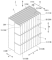
도 1a는, 본 발명의 필터 플리트 팩의 일 예를 모식적으로 나타내는 사시도이다.
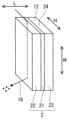
도 1b는, 도 1a의 필터 플리트 팩에서의 폭 방향의 한쪽 측면의 일부를 당해 폭 방향을 따라서 본 평면도, 및 에어 필터 여과재 및 통기 저해부를 포함하는 영역의 부분 확대도이다.
도 1c는, 도 1b의 필터 플리트 팩에서의 단면 C-C를 나타내는 단면도이다.
도 2는, 통기 저해부가 존재하지 않는 경우에 사이드 누설이 발생할 수 있는 것을 설명하기 위한 모식도이다.
도 3은, 통기 저해부를 갖는 본 발명의 필터 플리트 팩에 있어서 사이드 누설이 억제되는 것을 설명하기 위한 모식도이다.
도 4a는, 본 발명의 필터 플리트 팩의 다른 일 예를 모식적으로 나타내는 평면도, 및 에어 필터 여과재 및 통기 저해부를 포함하는 영역의 부분 확대도이다.
도 4b는, 본 발명의 필터 플리트 팩의 다른 일 예를 모식적으로 나타내는 평면도, 및 에어 필터 여과재 및 통기 저해부를 포함하는 영역의 부분 확대도이다.
도 5a는, 본 발명의 필터 플리트 팩의 다른 일 예를 모식적으로 나타내는 사시도이다.
도 5b는, 도 5a의 필터 플리트 팩에서의 폭 방향의 한쪽 측면의 일부를 당해 폭 방향을 따라서 본 평면도, 및 에어 필터 여과재 및 통기 저해부를 포함하는 영역의 부분 확대도이다.
도 5c는, 도 5b의 필터 플리트 팩에서의 단면 C-C를 나타내는 단면도이다.
도 6은, 본 발명의 필터 플리트 팩이 가질 수 있는 띠상체를 측면에 가질 수 있는 오목부의 꼭지각 θ1을 설명하기 위한 모식도이다.
도 7은, 본 발명의 필터 플리트 팩이 가질 수 있는 띠상체와, 당해 띠상체가 배치된 에어 필터 여과재 사이의 접촉각 θ2를 설명하기 위한 모식도이다.
도 8은, 본 발명의 필터 플리트 팩의 다른 일 예를 모식적으로 나타내는 평면도, 및 에어 필터 여과재 및 통기 저해부를 포함하는 영역의 부분 확대도이다.
도 9는, 본 발명의 필터 플리트 팩을 제조하는 방법의 일 예를 나타내는 모식도이다.
도 10은, 본 발명의 필터 플리트 팩을 제조하는 방법의 다른 일 예를 나타내는 모식도이다.
도 11은, 본 발명의 필터 플리트 팩을 제조하는 방법의 다른 일 예를 나타내는 모식도이다.
도 12는, 본 발명의 필터 플리트 팩을 제조하는 방법의 다른 일 예를 나타내는 모식도이다.
도 13은, 본 발명의 필터 플리트 팩이 가질 수 있는 띠상체의 일 예를 설명하기 위한 모식적인 단면도이다.
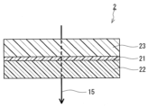
도 14는, 본 발명의 필터 플리트 팩이 구비하는 에어 필터 여과재의 일 예를 모식적으로 나타내는 단면도이다.
도 15는, 본 발명의 필터 플리트 팩이 구비하는 에어 필터 여과재의 다른 일 예를 모식적으로 나타내는 단면도이다.
도 16은, 본 발명의 필터 플리트 팩이 구비하는 에어 필터 여과재의 다른 일 예를 모식적으로 나타내는 단면도이다.
도 17a는, 본 발명의 에어 필터 유닛의 일 예를 모식적으로 나타내는 평면도이다.
도 17b는, 도 17a의 에어 필터 유닛의 단면 B-B를 나타내는 단면도이다.
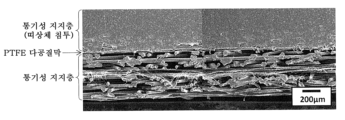
도 18은, 실시예 1에서 제작한 필터 플리트 팩에서의 띠상체 및 그 근방의 주사형 전자 현미경(SEM)에 의한 관찰 상(像)이다.
도 19는, 실시예 2에서 제작한 필터 플리트 팩에서의 띠상체 및 그 근방의 SEM에 의한 관찰 상이다.
도 20a는, 실시예 3에서 제작한 필터 플리트 팩에서의 띠상체 및 그 근방의 SEM에 의한 관찰 상이다.
도 20b는, 도 20a의 관찰 상에 있어서 띠상체와 에어 필터 여과재가 접하고 있는 부분을 확대한 상이다.
도 21a는, 비교예 1에서 제작한 필터 플리트 팩에서의 띠상체 및 그 근방의 SEM에 의한 관찰 상이다.
도 21b는, 도 21a의 관찰 상에 있어서 띠상체와 에어 필터 여과재가 접하고 있는 부분을 확대한 상이다.
도 22a는, 비교예 2에서 제작한 필터 플리트 팩에서의 띠상체 및 그 근방의 SEM에 의한 관찰 상이다.
도 22b는, 도 22a의 관찰 상에 있어서 띠상체와 에어 필터 여과재가 접하고 있는 부분을 확대한 상이다.1A is a perspective view schematically showing an example of a filter pleat pack of the present invention.
FIG. 1B is a plan view of a part of one side surface in the width direction of the filter pleat pack of FIG. 1A viewed along the width direction, and a partially enlarged view of a region including the air filter material and the ventilation blocking portion.
Fig. 1C is a cross-sectional view showing a section CC in the filter pleat pack of Fig. 1B.
Fig. 2 is a schematic diagram for explaining that side leakage may occur in the case where a ventilation-blocking portion does not exist.
Fig. 3 is a schematic diagram for explaining that side leakage is suppressed in the filter pleat pack of the present invention having a ventilation blocking portion.
Fig. 4A is a plan view schematically showing another example of the filter pleat pack of the present invention, and a partially enlarged view of a region including an air filter material and an airflow blocking portion.
Fig. 4B is a plan view schematically showing another example of the filter pleat pack of the present invention, and a partially enlarged view of a region including the air filter material and the ventilation blocking portion.
Fig. 5A is a perspective view schematically showing another example of the filter pleat pack of the present invention.
Fig. 5B is a plan view of a part of one side surface in the width direction of the filter pleat pack of Fig. 5A viewed along the width direction, and a partially enlarged view of a region including the air filter material and the ventilation blocking portion.
Fig. 5C is a cross-sectional view showing a section CC in the filter pleat pack of Fig. 5B.
6 is a schematic diagram for explaining the vertex angle θ 1 of a concave portion that may have a band-shaped body on a side surface of the filter pleat pack of the present invention.
Fig. 7 is a schematic diagram for explaining a contact angle θ 2 between a band-shaped body that the filter pleat pack of the present invention may have and an air filter medium on which the band-shaped body is disposed.
Fig. 8 is a plan view schematically showing another example of the filter pleat pack of the present invention, and a partially enlarged view of a region including an air filter material and a ventilation blocking portion.
Fig. 9 is a schematic diagram showing an example of a method for manufacturing the filter pleat pack of the present invention.
Fig. 10 is a schematic diagram showing another example of a method for manufacturing a filter pleat pack of the present invention.
Fig. 11 is a schematic diagram showing another example of a method for manufacturing a filter pleat pack of the present invention.
12 is a schematic diagram showing another example of a method for manufacturing a filter pleat pack of the present invention.
Fig. 13 is a schematic cross-sectional view for explaining an example of a band-shaped body that the filter pleat pack of the present invention may have.
Fig. 14 is a cross-sectional view schematically showing an example of an air filter material included in the filter pleat pack of the present invention.
Fig. 15 is a cross-sectional view schematically showing another example of the air filter material included in the filter pleat pack of the present invention.
Fig. 16 is a cross-sectional view schematically showing another example of the air filter material included in the filter pleat pack of the present invention.
17A is a plan view schematically showing an example of an air filter unit of the present invention.
Fig. 17B is a sectional view showing a section BB of the air filter unit of Fig. 17A.
Fig. 18 is an image observed by a scanning electron microscope (SEM) of a band-like body and its vicinity in the filter pleat pack produced in Example 1.
Fig. 19 is an SEM observation image of the band-like body and its vicinity in the filter pleat pack produced in Example 2.
Fig. 20A is an SEM observation image of a band-like body and its vicinity in the filter pleat pack produced in Example 3.
Fig. 20B is an enlarged image of a portion where the band-like body and the air filter material are in contact in the observation image of Fig. 20A.
Fig. 21A is an SEM observation image of a band-like body and its vicinity in a filter pleat pack produced in Comparative Example 1.
Fig. 21B is an enlarged image of a portion where the band-like body and the air filter material are in contact in the observation image of Fig. 21A.
Fig. 22A is an SEM observation image of a band-like body and its vicinity in the filter pleat pack produced in Comparative Example 2.
Fig. 22B is an enlarged image of a portion where the band-like body and the air filter material are in contact in the observation image of Fig. 22A.
이하, 본 발명의 실시 형태에 대하여 도면을 참조하면서 설명한다. 본 발명은 이하의 실시 형태에 한정되지는 않는다.EMBODIMENT OF THE INVENTION Hereinafter, embodiment of this invention is described, referring drawings. The present invention is not limited to the following embodiments.
[필터 플리트 팩][Filter Fleet Pack]
본 실시 형태의 필터 플리트 팩의 일 예를 도 1a 내지 도 1c에 나타낸다. 도 1b는, 도 1a의 필터 플리트 팩(1)에서의 폭 방향 W의 한쪽의 단부[11(11A)] 측의 측면[12(12A)]의 일부를 폭 방향 W를 따라 본(도 1a의 방향 B에서 본) 평면도, 및 당해 측면(12)에서의 에어 필터 여과재(2) 및 통기 저해부[3(3A)]를 포함하는 영역의 부분 확대도이다. 도 1c는, 도 1b의 필터 플리트 팩(1)에서의 단면 C-C를 나타내는 단면도이다. 도 1b에는, 필터 플리트 팩(1)에서의 길이 방향 L 및 높이 방향 H로 넓어지는 면이 도시되어 있다. 도 1c에는, 필터 플리트 팩(1)을 폭 방향 W 및 길이 방향 L로 넓어지는 면에서 절단한 단면이 도시되어 있다. 본 명세서에 있어서, 폭 방향 W는, 플리트상으로 접힌 에어 필터 여과재(2)의 플리트선(25)이 연장되는 방향이다. 길이 방향 L은, 필터 플리트 팩(1)을 투과하는 기류(기류 P)(14)가 향하는 방향(이하, 「기류(14)의 방향」이라고 기재함) 및 폭 방향 W와 직교하는 방향이다. 높이 방향 H는, 폭 방향 W 및 길이 방향 L의 양쪽에 직교하는 방향이며, 기류(14)의 방향이다. 도 1c의 단면은, 기류(14)의 방향을 따라서 본 단면이기도 하다. 도 1b, 도 1c 및 이후의 도면에서는, 설명을 알기 쉽게 하기 위해서, 통기 저해부(3)에 상당하는 부분에는 동일한 도트를 찍는다.An example of the filter pleat pack of this embodiment is shown in FIGS. 1A to 1C. FIG. 1B is a view of a part of the side surface 12 (12A) on the side of one end [11 (11A)] of the
도 1a 내지 도 1c의 필터 플리트 팩(1)은, 플리트상으로 접힌 에어 필터 여과재(2)로 구성된다. 에어 필터 여과재(2)는 제1 불소 수지 다공질막(21), 제1 통기성 지지층(22) 및 제2 통기성 지지층(23)을 구비한다. 제1 불소 수지 다공질막(21)은 제1 통기성 지지층(22) 및 제2 통기성 지지층(23)에 의해 끼워져 지지되어 있다. 제1 통기성 지지층(22)은 제1 불소 수지 다공질막(21)에 대하여 한쪽 측에 배치되어 있다. 보다 구체적으로는, 제1 통기성 지지층(22)은 제1 불소 수지 다공질막(21)에 대하여 에어 필터 여과재(2)를 투과하는 기류(기류 M)(15)의 하류측에 배치되어 있다.The
제1 통기성 지지층(22)은 폭 방향 W의 양쪽의 단부[13(13A, 13B)]의 각각에, 통기 저해부[3(3A, 3B)]를 갖는다. 통기 저해부(3)는 단부(13)를 따라 연장됨과 함께, 제1 통기성 지지층에서의 폭 방향 W의 통기를 저해한다. 통기 저해부(3)는 제1 통기성 지지층(22)의 일부이다. 통기 저해부(3)는 제1 불소 수지 다공질막(21)에 대하여 상기 한쪽 측에 위치한다. 보다 구체적으로는, 통기 저해부(3)는 제1 불소 수지 다공질막(21)에 대하여 기류(14, 15)의 하류측에 위치한다. 통기 저해부(3)는 제1 불소 수지 다공질막(21)에 접하고 있다(다시 말해, 제1 불소 수지 다공질막(21)에 접하도록 제1 통기성 지지층(22)의 내부로 확대되어 있음).The first air
도 2에 도시한 바와 같이, 통기 저해부(3)가 존재하지 않는 경우, 프레임체에 집어넣을 때에 측면(12)과 프레임체 사이의 틈(시일되지 않은 간극)으로의 노출 부분이 되는 에어 필터 여과재(2)의 단면(24)을 통과함과 함께, 제1 통기성 지지층(22)의 내부를 추가로 투과하여 기류(14, 15)의 하류측으로 빠져나가는 사이드 누설(16)이 발생할 수 있다. 사이드 누설(16)은 제1 불소 수지 다공질막(21)에 비하여, 제1 통기성 지지층(22)의 통기성이 높고, 포집 효율이 낮은 것에 기초한다. 본 발명자들의 검토에 의하면, 사이드 누설(16)에 의해, 상술한 포집 효율의 저하가 발생한다. 한편, 도 3에 도시한 바와 같이, 통기 저해부(3)가 존재하는 경우에는, 상기 간극으로의 노출 부분이 되는 단면(24)으로부터의 제1 통기성 지지층(22)을 통한 사이드 누설(16)은 억제된다. 이에 의해, 필터 플리트 팩(1)에서는, 프레임체로의 집어넣음에 있어서, 에어 필터 여과재(2)의 단면(24)의 전체를 덮지 않고 시일한 경우에 있어서도, 형성된 에어 필터 유닛의 포집 효율의 저하가 억제된다.As shown in Fig. 2, when the
도 1a 내지 도 1c의 통기 저해부(3)는 그 전체가 단부(13)에 위치하고 있다. 단, 통기 저해부(3)는 적어도 그 일부가 단부(13)에 위치하고 있어도 된다. 본 명세서에 있어서, 제1 통기성 지지층(22)의 폭 방향 W의 단부(13)란, 폭 방향 W의 중심선의 방향을 향해 단면(24)으로부터 넓어지는 띠상의 영역을 의미한다. 당해 영역의 폭(단부(13)의 폭)은 에어 필터 여과재(2)의 사이즈(필터 플리트 팩(1)의 사이즈)를 따라서도 다르지만, 예를 들어 2㎜ 이상이며, 5㎜ 이상, 10㎜ 이상, 20㎜ 이상, 30㎜ 이상, 나아가서는 40㎜ 이상이어도 된다. 단부(13)의 폭의 상한은, 예를 들어 에어 필터 여과재(2)의 폭의 10% 이하이다.1A to 1C, the entirety of the
마찬가지로, 본 명세서에 있어서, 필터 플리트 팩(1)의 폭 방향 W의 단부(11)란, 폭 방향 W의 중심선의 방향을 향해 측면(12)으로부터 넓어지는 띠상의 영역을 의미한다. 당해 영역의 폭(단부(11)의 폭)은 필터 플리트 팩(1)의 사이즈에 따라서도 다르지만, 예를 들어 2㎜ 이상이며, 5㎜ 이상, 10㎜ 이상, 20㎜ 이상, 30㎜ 이상, 나아가서는 40㎜ 이상이어도 된다. 단부(11)의 폭의 상한은, 예를 들어 필터 플리트 팩(1)의 폭 10% 이하이다.Similarly, in this specification, the
도 1a 내지 도 1c의 통기 저해부(3)는 제1 통기성 지지층(22)에서의 제1 불소 수지 다공질막(21) 측과는 반대 측의 표면(제1 표면)(91)에 도달되어 있다. 다시 말해, 통기 저해부(3)는 표면(91)으로부터 제1 불소 수지 다공질막(21)까지 도달하도록, 제1 통기성 지지층(22)의 내부로 확대되어 있다. 이 양태에서는, 사이드 누설(16)을 보다 확실하게 억제할 수 있다.1A to 1C, the air
도 1a 내지 도 1c의 통기 저해부(3)는 제1 통기성 지지층(22)에서의 길이 방향 L의 한쪽의 단부(20A)로부터 다른 쪽의 단부(20B)에 이르기까지, 단부(13)를 따라 연장되어 있다. 이 양태에서는, 사이드 누설(16)을 보다 확실하게 억제할 수 있다.1A to 1C, the
도 1a 내지 도 1c의 제1 통기성 지지층(22)은 폭 방향 W의 양쪽의 단부(13A, 13B)의 각각에 통기 저해부(3A, 3B)를 갖고 있다. 단, 제1 통기성 지지층(22)은 폭 방향 W의 적어도 한쪽의 단부(13)에 통기 저해부(3)를 갖고 있으면 된다. 또한, 에어 필터 유닛의 프레임체로의 집어넣음에 있어서, 필터 플리트 팩(1)에서의 통기 저해부(3)가 존재하지 않는 단부(11)에 대해서는, 예를 들어 에어 필터 여과재(2)의 단면(24)의 전체를 덮도록 간극을 시일하는 등의 공지된 방법에 의해, 당해 단부에서의 사이드 누설(16)을 억제하는 것이 바람직하다. 필터 플리트 팩(1)에서의 길이 방향 L의 단부에 대해서도 마찬가지이다. 원통형의 필터 플리트 팩(1)에서는, 길이 방향 L의 양쪽의 단부끼리를 접합해도 된다.The 1st air
상기 적어도 한쪽의 단부(13)에 있어서 제1 통기성 지지층(22)에는 제1 수지가 침투하고 있음과 함께, 통기 저해부(3)는 제1 통기성 지지층(22)에서의 제1 수지가 침투한 부분(301)을 포함하고 있어도 된다(도 4a 참조). 부분(301)에서는, 침투한 제1 수지에 의해 제1 통기성 지지층(22)의 통기 경로가 축소되고, 침투의 정도에 따라서는 폐색한다.While the first resin permeates into the first air
상기 적어도 한쪽의 단부(13)에 있어서 제1 통기성 지지층(22)은 열 융착 가공되어 있음과 함께, 통기 저해부(3)는 제1 통기성 지지층(22)에서의 상기 열 융착 가공이 이루어진 부분(302)을 포함하고 있어도 된다(도 4b 참조). 부분(302)에서는, 제1 통기성 지지층(22)을 구성하는 재료, 예를 들어 섬유 재료끼리가 열에 의해 융착되어 제1 통기성 지지층(22)의 통기 경로가 축소하고, 융착의 정도에 따라서는 폐색한다.In the at least one
부분(301, 302)은 표면(91)으로부터 제1 불소 수지 다공질막(21)까지 도달하도록, 제1 통기성 지지층(22)의 내부로 확대되어 있어도 된다.The
본 실시 형태의 필터 플리트 팩(1)이 다른 일 예를 도 5a 내지 도 5c에 나타낸다. 도 5b는, 도 5a의 필터 플리트 팩(1)에서의 폭 방향 W의 한쪽의 단부[11(11A)] 측의 측면[12(12A)]의 일부를 폭 방향 W를 따라 본 평면도, 및 당해 측면(12)에서의 에어 필터 여과재(2) 및 통기 저해부(3)를 포함하는 영역의 부분 확대도이다. 도 5c는, 도 5b의 필터 플리트 팩(1)에서의 단면 C-C를 나타내는 단면도이다. 도 5a 내지 도 5c의 필터 플리트 팩(1)은, 폭 방향 W의 양쪽의 단부[11(11A, 11B)]의 각각에, 당해 단부(11A, 11B)를 따라 연장되는 띠상체[7(7A, 7B)]를 갖는다. 띠상체(7)는 제1 수지를 포함한다. 띠상체(7)는 플리트상으로 접힌 에어 필터 여과재(2)에서의 제1 통기성 지지층(22) 측의 표면(제2 표면)에 배치된다. 보다 구체적으로는, 띠상체(7)는 에어 필터 여과재(2)에서의 기류(15)의 하류측의 표면에 배치된다. 또한, 띠상체(7)는 제1 불소 수지 다공질막(21)에 도달하도록, 상기 제2 표면으로부터 제1 통기성 지지층(22)의 내부에 침투되어 있다(도 5b 및 도 5c를 참조). 통기 저해부(3)는 제1 통기성 지지층(22)에서의 띠상체(7)가 침투된 부분을 포함한다. 또한, 띠상체(7)의 형상은, 기류(14)의 방향을 따라 보았을 때에 띠상이면 된다. 띠상에는, 끈상이 포함된다.Another example of the
띠상체(7)는 필터 플리트 팩(1)의 비드여도 된다. 플리트상으로 접힌 에어 필터 여과재로 구성되는 필터 플리트 팩에서는, 일반적으로, 에어 필터 여과재의 접힘 형상(플리트 형상)을 유지하기 위해서, 비드가 배치된다. 비드는, 통상 접힌 에어 필터 여과재의 플리트선과 교차하는 방향을 따라서 진행하도록, 에어 필터 여과재의 표면에 배치되어 있다.The band-
도 5a 내지 도 5c의 띠상체(7)는 그 전체가 단부(11)에 접하도록 배치되어 있다. 단, 띠상체(7)는 적어도 그 일부가 단부(11)에 접하도록 배치되어 있으면 된다. 또한, 도 5a 내지 도 5c의 띠상체(7)는 기류(14)의 방향을 따라 보았을 때에, 그 일부가, 에어 필터 여과재(2)의 단부(11) 측의 단면(24)으로부터 폭 방향 W의 외측(상기 중심선으로부터 이격되는 방향)으로 돌출되어 있다. 단, 띠상체(7)는 단면(24)으부터 외측으로 돌출되지 않고, 예를 들어 그 전체가, 단면(24)에 대하여 폭 방향 W의 내측(상기 중심선에 가까워지는 방향)에 위치하고 있어도 된다.The entire band-
도 5a 내지 도 5c의 필터 플리트 팩(1)은, 폭 방향 W의 양쪽의 단부(11A, 11B)의 각각에 띠상체(7A, 7B)를 갖고 있다. 필터 플리트 팩(1)은, 폭 방향 W의 적어도 한쪽의 단부(11)에 띠상체(7)를 갖고 있어도 된다.The
도 5a 내지 도 5c의 띠상체(7)는 에어 필터 여과재(2)에서의 한쪽 측의 플리트선[25(25A)]으로부터 다른 쪽 측의 플리트선[25(25B)]에 이르기까지, 당해 여과재(2)의 표면에 배치되어 있다. 보다 구체적으로는, 도 5a 내지 도 5c의 띠상체(7)는 에어 필터 여과재(2)에서의 기류(14)의 하류측의 플리트선[25(25A)]으로부터 상류측의 플리트선[25(25B)]에 이르기까지, 당해 여과재(2)의 표면에 배치되어 있다(도 5b 참조). 이 양태에서는, 사이드 누설(16)을 보다 확실하게 억제할 수 있다.5A to 5C, the band-
또한, 도 5a 내지 도 5c의 띠상체(7)는 길이 방향 L 및 높이 방향 H로 넓어지는 면에서 보았을 때에, 다시 말해, 측면(12)에 수직인 방향에서 보았을 때에, 상기 다른 쪽 측의 골접힘선[29(29B)]으로부터 골접힘선간 높이 H1의 90% 이상의 범위에 이르기까지, 상기 한쪽 측에 있어서 대향하는 에어 필터 여과재(2) 사이의 영역(27)을 충전하도록, 당해 여과재(2)의 표면에 배치되어 있다. 보다 구체적으로는, 도 5a 내지 도 5c의 띠상체(7)는 길이 방향 L 및 높이 방향 H로 넓어지는 면에서 보았을 때에, 다시 말해, 측면(12)에 수직인 방향에서 보았을 때에, 상류측의 골접힘선[29(29B)]으로부터 골접힘선간 높이 H1의 90% 이상의 범위에 이르기까지, 기류(14, 15)의 하류측에 있어서 대향하는 에어 필터 여과재(2) 사이의 영역(27)을 충전하도록, 당해 여과재(2)의 표면에 배치되어 있다(도 5b 참조). 이 양태에서는, 사이드 누설(16)을 보다 확실하게 억제할 수 있다. 띠상체(7)는 측면(12)에 수직인 방향에서 보았을 때에, 상기 다른 쪽 측(예를 들어, 도 5a 내지 도 5c의 예에 나타낸 바와 같이, 상류측)의 골접힘선(29B)으로부터 골접힘선간 높이 H1의 50% 이상, 60% 이상, 70% 이상, 80% 이상, 나아가서는 90% 이상의 범위에 이르기까지, 영역(27)을 충전하도록 당해 여과재(2)의 표면에 배치되어 있어도 된다. 본 명세서에 있어서 골접힘선(29)이란, 플리트상으로 접힌 에어 필터 여과재(2)의 접힘부(30)에서의 내측의 접음선을 의미한다. 또한, 접힘부(30)에서의 외측의 접음선이 플리트선(25)이다. 골접힘선간 높이 H1이란, 골접힘선(29)(예를 들어 골접힘선(29B))과, 에어 필터 여과재(2)를 따라 당해 골접힘선(29)에 인접하는 다른 골접힘선(29)(예를 들어 상기 한쪽 측의 골접힘선(29A)) 사이의 높이 방향 H의 이격 거리이다.5A to 5C, when viewed from a plane widened in the longitudinal direction L and height direction H, that is, when viewed from a direction perpendicular to the
띠상체(7)에서의, 접힌 에어 필터 여과재(2)의 상기 다른 쪽 측(예를 들어, 상기 예에 나타낸 바와 같이, 상류측)의 골접힘선(29B)과, 에어 필터 여과재(2)를 따라 골접힘선(29B)에 인접한 상기 한쪽 측(예를 들어, 상기 예에 나타낸 바와 같이, 하류측)의 2개의 골접힘선(29A, 29A')에 접하는 면(37)의 사이에 위치하는 부분(도 5b 참조; 이하, 당해 부분을 부분 X라 기재)을 기류(14)의 방향을 따라서 본 단면(도 5c의 단면에 상당함; 이하, 단면 Y라 기재)에 있어서, 비 W1/W0은, 예를 들어 0.6 이상이며, 0.65 이상, 0.7 이상, 0.75 이상, 0.8 이상, 0.85 이상, 나아가서는 0.9 이상이어도 된다. 단, W0은, 단면 Y에서의 띠상체(7)의 폭이다. W1은, 단면 Y에 있어서, 띠상체(7)가 제1 불소 수지 다공질막(21)과 접하는 부분의 폭이다. 비 W1/W0이 클수록, 사이드 누설(16)을 보다 확실하게 억제할 수 있다. 단면 Y는, 띠상체(7)에서의 영역(27)을 충전하는 부분에 위치하고 있어도 된다. 띠상체(7)에 대하여 폭이란, 폭 방향 W의 길이를 의미한다. 폭 W0은, 골접힘선(29B)을 변경하여 선택한 적어도 3개의 띠상체(7)의 각각에 대하여 구한 단면 Y에서의 폭의 평균으로서 구할 수 있다. 폭 W1은, 골접힘선(29B)을 변경하여 선택한 적어도 3개의 띠상체(7)의 각각에 대하여 구한, 단면 Y에 있어서 띠상체(7)가 제1 불소 수지 다공질막(21)과 접하고 있는 부분의 폭(당해 부분이 복수 있는 경우에는, 개개의 폭 합계)의 평균으로서 구할 수 있다. 제1 불소 수지 다공질막(21)에 도달되지 않은 띠상체의 폭 W1은 0(제로)이다. 영역(27)을 충전하고 있는 부분에 위치하는 단면 Y에서는, 띠상체(7)는 상기 한쪽 측(예를 들어, 상기 예에 나타낸 바와 같이, 기류(14, 15)의 하류측)에 있어서 대향하는 양쪽의 에어 필터 여과재(2)에 접하고 있다. 이 경우에는, 적어도 한쪽의 접촉면에 있어서 상기 비가 충족되어 있어도 되며, 양쪽의 접촉면에 있어서 상기 비가 충족되어 있어도 된다.The
띠상체(7)의 부분 X를 기류(14)의 방향을 따라서 본 단면 Y에 있어서, 띠상체(7)가 제1 불소 수지 다공질막(21)과 접하는 부분의 폭 W1은, 예를 들어 1.0㎜ 이상이며, 1.2㎜ 이상, 1.4㎜ 이상, 1.5㎜ 이상, 1.7㎜ 이상, 1.9㎜ 이상, 나아가서는 2.0㎜ 이상이어도 된다. 폭 W1이 클수록, 사이드 누설(16)을 보다 확실하게 억제할 수 있다. 폭 W1의 상한은, 예를 들어 5.0㎜이다.In the section Y of the portion X of the band-
띠상체(7)의 부분 X를 기류(14)의 방향을 따라서 본 단면 Y는, 편평상이어도 된다. 도 5a 내지 도 5c에 도시한 띠상체(7)는 이 양태에 해당한다. 단면 Y가 편평상이면, 비 W1/W0 및 폭 W1을 보다 확실하게 크게 할 수 있다. 편평상인 단면 Y의 종횡비(폭 W0에 대한 세로 방향의 길이 L0의 비 L0/W0; 도 5c 참조)는, 예를 들어 1 미만이고, 0.8 이하, 0.7 이하, 0.6 이하, 0.5 이하, 0.4 이하, 0.3 이하, 나아가서는 0.2 이하여도 된다. 비 L0/W0의 하한은, 예를 들어 0.1 이상이다. 세로 방향의 길이 L0은, 골접힘선(29B)을 변경하여 선택한 적어도 3개의 띠상체(7)의 각각에 대하여 구한, 상기 단면에서의 세로 방향의 길이 평균으로서 구할 수 있다. 띠상체(7)에 대하여 세로 방향의 길이란, 길이 방향 L의 길이를 의미한다.A cross-section Y of the portion X of the band-
띠상체(7)의 부분 X를 기류(14)의 방향을 따라서 본 단면 Y에 있어서, 띠상체(7)의 적어도 한쪽 측면(폭 방향의 측면)(31)이 오목부를 갖지 않아도 되며, 양쪽의 측면(31)이 오목부를 갖지 않아도 된다(도 5c 참조). 이 경우, 비 W1/W0 및 폭 W1을 보다 확실하게 크게 할 수 있다. 또한, 띠상체(7)가 측면(31)에 오목부(32)를 갖는 경우에는, 오목부(32)는 둔각(90° 초과)인 꼭지각 θ1을 갖고 있어도 된다(도 6 참조). 오목부(32)의 꼭지각 θ1은, 상기 단면에서의 오목부(32)의 양쪽의 에지부(33)와, 오목부(32)의 표면에서의, 당해 에지부(33)끼리를 연결하는 선분(34)(오목부(32)의 개구 접선에 상당)으로부터 가장 떨어진 점(정점)(35)에 의해 구성되는 삼각형(36)의 꼭지각으로서 정해진다.In a cross-section Y of the portion X of the band-
띠상체(7)와 에어 필터 여과재(2) 사이의 접촉각 θ2(도 7 참조)는 둔각(90° 초과)이어도 된다. 접촉각 θ2가 둔각인 것은, 기류(14)의 방향을 따라서 본 띠상체(7)의 단면 Y를 관찰하여 판단할 수 있다. 또한, 접촉각 θ2는, 에어 필터 여과재(2)의 표면, 보다 구체적으로는 플리트면(26) 사이의 각도로서 정해진다. 본 명세서에 있어서 플리트면이란, 플리트상으로 접힌 에어 필터 여과재(2)의 표면에서의, 어떤 하나의 플리트선(25)(예를 들어 플리트선(25B))과, 에어 필터 여과재(2)를 따라 당해 플리트선(25)에 인접하는 다른 플리트선(25)(예를 들어 플리트선(25A)) 사이의 영역을 의미한다.The contact angle θ 2 (see FIG. 7 ) between the band-
도 5a 내지 도 5c의 필터 플리트 팩(1)에서는, 제1 통기성 지지층(22)에 침투하여 통기 저해부(3)를 구성하는 띠상체(7)에 의해, 영역(27)이 충전되어 있다. 단, 영역(27)은 통기 저해부(3)와는 독립적으로, 제2 수지에 의해 충전되어 있어도 된다. 다시 말해, 본 실시 형태의 필터 플리트 팩(1)에서는, 필터 플리트 팩(1)에서의 폭 방향 W의 단부(11)이며, 제1 통기성 지지층(22)이 통기 저해부(3)를 갖고 있는 단부(11)를 폭 방향 W를 따라 보았을 때에(측면(12)에 수직인 방향에서 보았을 때에), 상기 한쪽 측(예를 들어, 상기 예에 나타낸 바와 같이, 기류(15)의 하류측)에 있어서 대향하는 에어 필터 여과재(2) 사이의 영역(27)을 충전하도록 제2 수지가 배치되어 있어도 된다. 이 양태에 있어서도, 사이드 누설(16)을 보다 확실하게 억제할 수 있다. 또한, 양쪽의 단부(11)에 있어서 제1 통기성 지지층(22)이 통기 저해부(3)를 갖고 있는 경우에는, 적어도 하나의 단부(11)에서의 영역(27)에 제2 수지가 배치되어 있어도 된다.In the
당해 양태의 일 예를 도 8에 나타낸다. 도 8은, 도 5b와 마찬가지로, 필터 플리트 팩(1)에서의 폭 방향 W의 한쪽의 단부[11(11A)] 측의 측면[12(12A)]의 일부를 폭 방향 W를 따라 본 평면도, 및 당해 측면(12)에서의 에어 필터 여과재(2) 및 통기 저해부(3)를 포함하는 영역의 부분 확대도이다. 영역(27)은 제2 수지(8)에 의해 충전되어 있다.An example of this embodiment is shown in FIG. 8 . 8 is a plan view of a part of the side surface 12 (12A) on the side of one end [11 (11A)] of the
제2 수지(8)에 의한 영역(27)의 충전은 부분이어도 된다. 필터 플리트 팩(1)에서의 폭 방향 W의 단부(11)이며, 제1 통기성 지지층(22)이 통기 저해부(3)를 갖고 있는 단부(11)를 폭 방향 W를 따라 보았을 때에, 제2 수지는, 상기 다른 쪽 측(예를 들어, 필터 플리트 팩(1)을 투과하는 기류(14)에 대하여 상류측)에 위치하는 골접힘선(29B)으로부터 골접힘선간 높이 H1의 50% 이상, 60% 이상, 70% 이상, 80% 이상, 나아가서는 90% 이상의 범위에 이르기까지, 영역(27)을 충전하도록 배치되어 있어도 된다.The filling of the
도 8의 통기 저해부(3)는 상술한 통기 저해부(301 또는 302)여도 된다. 단, 통기 저해부(3)는 상기 예에 한정되지는 않는다.The
제1 수지 및 제2 수지(8)는, 예를 들어 핫 멜트 수지 및 경화성 수지이며, 필터 플리트 팩(1)의 유연성을 보다 확실하게 확보할 수 있다는 관점에서는, 핫 멜트 수지가 바람직하다. 단, 제1 수지 및 제2 수지(8)는 상기 예에 한정되지는 않는다. 또한, 제1 수지 및 제2 수지(8)로부터는, 광경화성 수지가 제외되어 있어도 된다. 광경화성 수지는, 경화 전의 상태에서의 점도가 낮기 때문에, 띠상체(7)의 형상이나 영역(27)에서의 수지의 충전 형상의 제어가 어려운 경우가 있다.The first resin and the
핫 멜트 수지의 예는, 폴리아미드계 수지, 폴리올레핀계 수지 및 폴리비닐알코올계 수지이다. 또한, 에틸렌-아세트산비닐 공중합체(EVA) 수지는, 폴리비닐알코올계 수지에 포함된다.Examples of hot melt resins are polyamide-based resins, polyolefin-based resins, and polyvinyl alcohol-based resins. Moreover, ethylene-vinyl acetate copolymer (EVA) resin is contained in polyvinyl alcohol-type resin.
제1 수지와 제2 수지(8)는, 동일해도 되고 달라도 된다.The first resin and the
필터 플리트 팩(1)은, 예를 들어 이하의 방법에 의해 제조할 수 있다. 단, 필터 플리트 팩(1)의 제조 방법은, 이하의 방법에 한정되지는 않는다.The
도 9에는, 필터 플리트 팩(1)을 제조하는 방법의 일 예가 도시되어 있다. 도 9의 방법은, 제1 프로세스 및 제2 프로세스를 포함한다. 제1 프로세스에서는, 제1 불소 수지 다공질막(21)과 제1 통기성 지지층(22)을 구비한 여과재 원단(61)에서의 폭 방향 WM의 적어도 한쪽의 단부(62)(도 9의 예에서는, 양쪽의 단부(62A, 62B)의 각각)에 대하여 단부(62)를 따라 연장됨과 함께, 제1 통기성 지지층(22)에서의 폭 방향 WM의 통기를 저해하는 통기 저해부(3)를 형성한다. 제2 프로세스에서는, 폭 방향 WM에 플리트선(25)이 연장되도록 여과재 원단(61)을 플리트 가공하여 필터 플리트 팩(1)을 얻는다. 플리트 가공에서는, 시트형의 여과재 원단(61)에 대하여 산접힘선인 플리트선(25A) 및 골접힘선(29B)이 교대로 형성됨과 함께, 골접힘선(29B)을 사이에 두도록 인접하여 플리트면(26A, 26B)이 상승된다. 도 9의 예에서는, 여과재 원단(61)에서의 제1 통기성 지지층(22) 측의 표면에 대하여 유동 상태에 있는 제1 수지(63)를 도포하고, 도포한 수지(63)를 제1 통기성 지지층(22)에 침투시켜 통기 저해부(3)를 형성한다. 유동 상태는, 용융 상태여도 된다. 제2 프로세스의 플리트 가공은, 공지된 방법, 예를 들어 레시프로식이나 로터리식의 가공기에 의해 실시할 수 있다.9 shows an example of a method for manufacturing the
여과재 원단(61)은 플리트 가공되지 않고, 또한, 통기 저해부(3)를 갖지 않는 것 이외에는, 에어 필터 여과재(2)와 마찬가지의 구성을 가질 수 있다.The filter material fabric 61 may have a configuration similar to that of the air
필터 플리트 팩(1)을 제조하는 방법의 다른 일 예를 도 10에 도시한다. 도 10의 방법은, 열 융착 가공에 의해 통기 저해부(3)를 형성하는 것 이외에는, 도 9의 방법과 동일하다. 당해 방법에서는, 여과재 원단(61)에서의 폭 방향 WM의 적어도 한쪽의 단부(62)에 대하여 열(64)이 인가됨으로써 통기 저해부(3)가 형성된다. 도 10의 예에서는, 여과재 원단(61)에서의 제1 통기성 지지층(22)의 측으로부터 열(64)이 인가된다. 열(64)은, 예를 들어 제1 통기성 지지층(22)을 구성하는 재료, 예를 들어 섬유 재료가 용융되어 서로 융착하도록 인가된다.Another example of a method of manufacturing the
필터 플리트 팩(1)을 제조하는 방법의 다른 일 예를 도 11에 도시한다. 도 11의 방법은, 열 융착 가공에 의해 통기 저해부(3)를 형성하는 것 이외에는, 도 9의 방법과 동일하다. 당해 방법에서는, 여과재 원단(61)에서의 폭 방향 WM의 적어도 한쪽의 단부(62)에 대하여 롤러(65)에 의해 열과 압력이 인가되고, 통기 저해부(3)가 형성된다. 도 11의 예에서는, 여과재 원단(61)에서의 제1 통기성 지지층(22)의 측에 롤러(65)가 접하고 있다.Another example of a method of manufacturing the
제1 수지의 침투 및 열 융착 가공의 양쪽을 실시하여 통기 저해부(3)를 형성해도 된다.The ventilation-blocking
필터 플리트 팩(1)을 제조하는 방법의 다른 일 예를 도 12에 도시한다. 도 12의 방법에서는, 여과재 원단(61)을 플리트 가공할 때에, 핫 멜트 수지를 포함하는 띠상체(7)가 형성된다. 당해 방법에서는, 여과재 원단(61)이 지면의 우측으로부터 좌측으로 반송되는 동안에, 제1 프로세스 및 제2 프로세스가 실시된다. 제1 프로세스에서는, 시트형의 여과재 원단(61)에서의 제1 통기성 지지층(22) 측의 표면에 대하여 유동 상태에 있는 수지(41)가 도포된다. 수지(41)는, 통상 띠상체(7)를 구성하는 수지와 동일하다. 유동 상태는, 용융 상태여도 된다. 수지(41)는 전형적으로는, 띠상으로 도포된다. 수지(41)가 도포된 여과재 원단(61)은 제2 프로세스로 반송되어 플리트 가공된다. 플리트 가공에서는, 시트형의 여과재 원단(61)에 대하여 수지(41)의 도포면을 보았을 때에, 산접힘선인 플리트선(25A) 및 골접힘선(29B)이 교대로 형성됨과 함께, 골접힘선(29B)을 사이에 두도록 인접하여 상승되는 플리트면(26A, 26B)이 수지(41)에 의해, 보다 구체적으로는, 플리트면(26A) 위에 배치된 수지(41A)와 플리트면(26B) 위에 배치된 수지(41B)가 서로 접합함으로써 고정된다. 접합한 수지(41A, 41B)는 냉각 후에 띠상체(7)가 된다. 에어 필터 여과재(2)의 플리트 가공은, 상기 플리트선(25A) 및 골접힘선(29B)의 형성, 그리고 플리트면(26A, 26B)의 띠상체(7)에 의한 고정이 반복 진행됨으로써 이루어진다. 이 방법에서는, 상기 한쪽 측(예를 들어, 기류(15)의 하류측)에 있어서 대향하는 에어 필터 여과재(2) 사이의 영역(27)을 충전하도록 띠상체(7)를 형성할 수 있다.Another example of a method for manufacturing the
도 12의 제1 프로세스에서는, 여과재 원단(61)에 도포하는 수지(41)의 온도(도포 온도)를, 통상보다 높게 하는 것이 바람직하다. 이에 의해, 수지(41)의 점도가 저하되고, 제1 통기성 지지층(22)으로의 수지(41)의 침투가 촉진된다. 도포 온도는, 예를 들어 통상의 도포 온도에 비하여 10℃ 이상 높고, 15℃ 이상, 20℃ 이상, 25℃ 이상, 나아가서는 30℃ 이상 높아도 된다. 구체적인 도포 온도는, 수지(41)의 종류에 따라서도 다르지만, 수지(41)가 EVA 수지인 경우에는, 예를 들어 150 내지 180℃이고, 160 내지 170℃여도 된다.In the 1st process of FIG. 12, it is preferable to make the temperature (application temperature) of the
또한, 도 12의 제1 프로세스에서는, 여과재 원단(61)에 도포하는 수지(41)의 도포폭을, 통상보다 크게 하는 것이 바람직하다. 이에 의해, 도포한 수지(41)의 열용량이 커지고, 도포 후에서의 수지(41)의 온도 저하가 완만해져서, 제1 통기성 지지층(22)으로의 수지(41)의 침투가 촉진된다. 도포폭은, 예를 들어 통상의 도포폭에 비하여 +(플러스) 0.3㎜이며, +0.5㎜, +0.7㎜, +1.0㎜, +1.2㎜, 나아가서는 +1.4㎜여도 된다. 구체적인 도포폭은, 수지(41)의 종류 및 도포 온도에 따라서도 다르지만, 수지(41)가 EVA 수지이며 또한 도포 온도가 150℃ 이상인 경우에는, 예를 들어 1.5㎜ 이상, 1.7㎜ 이상, 나아가서는 2.0㎜ 이상이어도 된다. 도포폭의 상한은, 필터 플리트 팩(1)으로서 필요한 여과 면적이 확보 가능한 한 한정되지 않고, 예를 들어 5.0㎜ 이하이다.In addition, in the 1st process of FIG. 12, it is preferable to make the coating width of
도 12의 제1 프로세스에 있어서 에어 필터 여과재(2)에 도포하는 수지(41)의 도포 온도를 높게 하거나, 및/또는 도포폭을 크게 함으로써, 예를 들어 상기 비 W1/W0의 범위를 충족하는 띠상체(7)나 상기 폭 W1의 범위를 충족하는 띠상체(7)의 형성이 보다 확실해진다.In the first process of FIG. 12 , by increasing the coating temperature of the
또한, 제1 프로세스에 있어서 에어 필터 여과재(2)에 도포하는 수지(41)의 도포 온도를 높게 하거나, 및/또는 도포폭을 크게 함으로써, 편평상의 단면 Y를 갖는 띠상체(7)나 단면 Y에 있어서 적어도 한쪽 측면(31)이 오목부(32)를 갖지 않는 띠상체(7)의 형성이 보다 확실해진다.Further, by increasing the coating temperature of the
도 12의 방법에 있어서 띠상체(7)는 플리트면(26A) 위에 도포된 수지(41A)와 플리트면(26B) 위에 도포된 수지(41B)가 제2 프로세스에 있어서 서로 접합하고, 냉각시켜 형성된다. 수지(41A) 및 수지(41B)에서는, 우선 도포된 수지(41A)의 쪽이 접합 시의 온도가 낮아지고, 다시 말해, 수지(41A)의 쪽이 접합 시의 유동성이 낮아진다. 이 때문에, 접합에 의해 형성된 띠상체(7)는, 예를 들어 도 13에 도시한 바와 같이, 수지(41A)에서 유래되는 부분(42A)에 있어서 도포 시의 형상, 예를 들어 원형 또는 타원형의 단면을 갖는 끈상이 유지되기 쉽고, 수지(41B)에서 유래되는 부분(42B)에 있어서 강하게 변형된 단면의 형상으로 되기 쉽다. 한편, 제1 프로세스에 있어서 여과재 원단(61)에 도포하는 수지(41)의 도포 온도를 높게 하거나, 및/또는 도포폭을 크게 하면, 수지(41A)의 온도 저하가 지연됨으로써, 수지(41A)에서 유래되는 부분(42A)에 대해서도 접합 시의 변형이 촉진된다. 이에 의해, 예를 들어 편평상의 단면 Y를 갖는 띠상체(7)나 단면 Y에 있어서 적어도 한쪽 측면(31)이 오목부(32)를 갖지 않는 띠상체(7)의 형성이 보다 확실해진다. 또한, 도 13에 도시한 띠상체(7)의 단면 Y에서는, 띠상체(7)의 양쪽 측면(31)은 꼭지각 θ1이 예각인 오목부(32)를 갖고 있다. 또한, 당해 단면 Y에 있어서 수지(41A)에서 유래되는 부분(42A)의 폭 W2는, 수지(41A)의 도포폭을 거의 유지하고 있다.In the method shown in Fig. 12, the band-
상기 각 예에 나타낸 필터 플리트 팩의 제조 방법은,The manufacturing method of the filter pleat pack shown in each of the above examples,
제1 불소 수지 다공질막(21)과 제1 통기성 지지층(22)을 구비한 여과재 원단(61)에서의 폭 방향 WM의 적어도 한쪽의 단부(62)에 대하여 단부(62)를 따라 연장됨과 함께, 제1 통기성 지지층(22)에서의 폭 방향 WM의 통기를 저해하는 통기 저해부(3)를 형성하는 것과,It extends along the
상기 폭 방향 WM에 플리트선(25)이 연장되도록 여과재 원단(61)을 플리트 가공하여 필터 플리트 팩(1)을 얻는 것을 포함하고 있다.and obtaining the
제1 불소 수지 다공질막(21)에 대하여 상기 다른 쪽 측(예를 들어, 기류(14, 15)의 상류측)에 위치하는 층, 예를 들어 제2 통기성 지지층(23)에서의 폭 방향 W의 통기를 저해하는 추가적인 통기 저해부는 형성되어 있어도 되고 없어도 된다. 상기 도시한 각 필터 플리트 팩(1)에 있어서 상기 다른 쪽 측에 위치하는 층은, 상기 추가적인 통기 저해부를 갖지 않는다.A layer located on the other side of the first fluororesin porous membrane 21 (eg, the upstream side of the air streams 14 and 15), for example, the second air
띠상체(7)는 필터 플리트 팩(1)에서의 상기 다른 쪽 측(예를 들어, 기류(14)의 상류측)에 배치되어 있어도 되고, 배치되어 있지 않아도 된다. 상기 도시한 각 필터 플리트 팩(1)에서는, 상기 다른 쪽 측에 띠상체(7)는 배치되어 있지 않다. 또한, 폭 방향 W의 단부(11A, 11B)에서의 상기 다른 쪽 측에는, 띠상체(7) 이외의 다른 부재도 배치되어 있지 않다. 폭 방향의 단부(11A, 11B)에 있어서, 에어 필터 여과재(2)에서의 상기 다른 쪽 측 표면은 노출되어 있다.The band-
(에어 필터 여과재)(Air filter material)
에어 필터 여과재(2)의 일 예를 도 14에 도시한다. 도 14의 에어 필터 여과재(2)는 상기 도시한 각 필터 플리트 팩(1)이 구비하는 여과재이며, 에어 필터 여과재(2)를 투과하는 기류(15)의 상류측에서, 제2 통기성 지지층(23), 제1 불소 수지 다공질막(21) 및 제1 통기성 지지층(22)이 순서대로 배치된 3층 구조를 갖는다. 제2 통기성 지지층(23)과 제1 불소 수지 다공질막(21)은 서로 접합되어 있다. 제1 불소 수지 다공질막(21)과 제1 통기성 지지층(22)은 서로 접합되어 있다. 도 14의 에어 필터 여과재(2)에서는, 한쪽의 최외층(기류(15)의 유입하는 층)이 제2 통기성 지지층(23)이며, 다른 쪽의 최외층(기류(15)가 배출되는 층)이 제1 통기성 지지층(22)이다.An example of the
(제1 불소 수지 다공질막)(First fluororesin porous film)
제1 불소 수지 다공질막(21)은 에어 필터 여과재(2)의 메인 필터로서 기능할 수 있는 층이다. 불소 수지 다공질막(21)은 전형적으로는, 미세한 섬유형 구조체인 무수의 불소 수지의 피브릴에 의해 구성된다. 불소 수지 다공질막(21)은 피브릴에 접속된 불소 수지의 노드(결절부)를 갖고 있어도 된다.The first fluororesin
불소 수지 다공질막(21)은 주로 불소 수지로 구성된다. 「주로 불소 수지로 구성된다」라 함은, 불소 수지 다공질막(21)에 포함되는 모든 성분 중에서 불소 수지의 함유율이 가장 큰 것을 의미한다. 불소 수지 다공질막(21)에서의 불소 수지의 함유율은, 예를 들어 50중량% 이상이며, 60중량% 이상, 70중량% 이상, 80중량% 이상, 90중량% 이상, 나아가서는 95중량% 이상이어도 된다. 불소 수지 다공질막(21)은 불소 수지 이외에, 예를 들어 필러를 포함할 수 있다.The fluororesin
불소 수지의 예는, PTFE,에틸렌-테트라플루오로에틸렌-헥사플루오로프로필렌 공중합체(EFEP), 테트라플루오로에틸렌-헥사플루오로프로필렌-불화비닐리덴 공중합체(THV), 테트라플루오로에틸렌-헥사플루오로프로필렌 공중합체(FEP), 테트라플루오로에틸렌-퍼플루오로알콕시에틸렌 공중합체(PFA) 및 에틸렌-테트라플루오로에틸렌 공중합체(ETFE)이다.Examples of the fluororesin include PTFE, ethylene-tetrafluoroethylene-hexafluoropropylene copolymer (EFEP), tetrafluoroethylene-hexafluoropropylene-vinylidene fluoride copolymer (THV), and tetrafluoroethylene-hexafluoropropylene copolymer (THV). fluoropropylene copolymer (FEP), tetrafluoroethylene-perfluoroalkoxyethylene copolymer (PFA) and ethylene-tetrafluoroethylene copolymer (ETFE).
불소 수지 다공질막(21)은 2종 이상의 불소 수지를 포함하고 있어도 된다.The
불소 수지 다공질막(21)은 PTFE 다공질막이어도 된다.The
불소 수지 다공질막(21)은, 예를 들어 미소성의 불소 수지의 분말과 액상 윤활제의 혼화물을 압출 및/또는 압연 등의 방법에 의해 필름에 성형하고, 얻어진 미소성의 필름으로부터 액상 윤활제를 제거한 후, 이것을 연신함으로써 형성할 수 있다. 미소성 필름의 형성 후, 임의의 타이밍에 있어서, 불소 수지의 융점 이상 온도로 필름을 가열하는 소성을 실시해도 된다. 액상 윤활제의 예는, 나프타, 화이트 오일, 유동 파라핀 등의 탄화수소유이다. 단, 액상 윤활제는, 불소 수지의 분말 표면을 적실 수 있음과 함께, 후에 제거할 수 있는 것이면 한정되지는 않는다. 연신의 일 예는, 미소성 필름의 MD(길이 방향)에 대한 연신 배율 2 내지 60배, 연신 온도 150 내지 390℃의 연신과, 당해 필름의 TD(폭 방향)에 대한 연신 배율 10 내지 60배, 연신 온도 40 내지 150℃의 연신을 조합한 2축 연신이다. 단, 불소 수지 다공질막(21)의 제조 방법은, 필터 플리트 팩(1) 및 이것을 구비하는 에어 필터 유닛의 사용 용도에 따른 포집 성능이 얻어지는 한, 한정되지는 않는다.The
불소 수지 다공질막(21)의 두께는, 예를 들어 0.1 내지 100㎛이며, 0.5 내지 80㎛, 나아가서는 1 내지 50㎛여도 된다.The thickness of the porous
불소 수지 다공질막(21)의 기공률은, 예를 들어 70 내지 98%이다. 기공률은, 다음과 같이 측정할 수 있다. 평가 대상물인 불소 수지 다공질막(21)을 일정한 치수(예를 들어, 직경 6㎝의 원형)로 잘라내어, 그 체적 및 질량을 구한다. 얻어진 체적 및 질량을 이하의 식 (1)에 대입하여 기공률을 산출할 수 있다. 식 (1)의 V(단위: ㎤)는 상기 체적, W(단위: g)는 상기 질량, D(단위: g/㎤)는 불소 수지의 진밀도이다.The porosity of the
기공률(%)=100×[V-(W/D)]/V …(1)Porosity (%) = 100 x [V-(W/D)]/V... (One)
불소 수지 다공질막(21)의 평량은, 예를 들어 0.05 내지 10g/㎡이며, 0.1 내지 5g/㎡, 나아가서는 0.3 내지 3g/㎡여도 된다.The basis weight of the
불소 수지 다공질막(21)의 투과 유속 5.3㎝/초에서의 압력 손실 PD는, 예를 들어 10 내지 500Pa이며, 20 내지 400Pa, 나아가서는 40 내지 350Pa여도 된다.The pressure loss PD of the
에어 필터 여과재(2) 및 에어 필터 여과재(2)를 구성하는 각 층의 압력 손실 PD는, 다음과 같이 평가할 수 있다. 평가 대상물인 여과재 또는 층을, 유효 면적 100㎠의 원형 홀더에 세트한다. 다음으로, 세트한 평가 대상물에 공기를 투과시키고, 통과하는 공기의 선속도를 유량계로 5.3㎝/초로 조정했을 때의 압력 손실을 압력계(마노미터)로 측정한다. 1개의 평가 대상물에 대하여 8회 압력 손실을 측정하고, 그 평균을 압력 손실 PD로 한다.The
불소 수지 다공질막(21)에 대하여, 입경 0.1 내지 0.2㎛의 범위에 개수 피크를 갖는 다분산 입자인 폴리알파올레핀(PAO) 입자(이하, 다분산 PAO 입자라고 기재함)를 사용하여, 평가 대상 입경 0.1 내지 0.2㎛ 및 투과 유속 5.3㎝/초의 조건에서 측정한 포집 효율 CE는, 예를 들어 60 내지 99.99999%이며, 90 내지 99.9999%, 나아가서는 99 내지 99.999%여도 된다.For the
에어 필터 여과재(2) 및 에어 필터 여과재(2)를 구성하는 각 층의 포집 효율 CE는, 다음과 같이 평가할 수 있다. 평가 대상물인 여과재 또는 층을, 유효 면적 100㎠의 원형 홀더에 세트한다. 다음으로, 세트한 평가 대상물에 공기를 투과시키고, 통과하는 공기의 선속도를 유량계로 5.3㎝/초로 조정한다. 다음으로, 다분산 PAO 입자를, 입경 0.1 내지 0.2㎛의 입자의 농도가 4×10⁸개/L 이상이 되도록, 평가 대상물을 통과하는 공기에 포함시킨다. 다분산 PAO 입자는, 예를 들어 정출력 에어로졸 아토마이저를 사용하여 발생시킬 수 있다. 그 후, 홀더의 하류에 배치한 파티클 카운터를 사용하여, 평가 대상물을 통과한 공기에 포함되는 다분산 PAO 입자의 농도를 평가 대상 입경의 범위에 대하여 구하고, 이하의 식 (2)에 의해, 평가 대상물의 포집 효율 CE를 산출한다. 식 (2)의 입자 농도는, 상류측 및 하류측 모두, 평가 대상 입경의 범위에 있는 입자의 농도이다. 상류측의 입자 농도는, 다분산 PAO 입자를 포함시킨 상기 공기를, 평가 대상물을 홀더에 세트하지 않은 상태에서 흘리고, 이것을 상기 파티클 카운터에 의해 해석하여 구할 수 있다. 또한, 다분산 PAO 입자는, 통상 입경 0.1 내지 0.2㎛의 범위에만 개수 피크를 갖는 싱글 피크 입자이다.The
포집 효율 CE=[1-(하류측의 입자 농도)/(상류측의 입자 농도)]×100(%) … (2)Collection efficiency CE=[1-(particle concentration on the downstream side)/(particle concentration on the upstream side)]×100 (%) . (2)
불소 수지 다공질막(21)에 대하여, 이하의 식 (3)에 의해 구해지는 PF(Performance Factor)값은, 예를 들어 20 이상이며, 22 이상, 23 이상, 25 이상, 27 이상, 28 이상, 나아가서는 30 이상이어도 된다. PF값의 상한은, 예를 들어 40 이하이며, 38 이하, 36 이하, 나아가서는 35 이하여도 된다. 식 (3)의 PD는 압력 손실, CE는 포집 효율이다. 단, 식 (3)에서의 압력 손실 PD의 단위는 ㎜H2O이다.For the fluororesin
PF값={-log[100-CE)/100]/PD}×100 …(3)PF value={-log[100-CE)/100]/PD}×100 … (3)
도 14의 불소 수지 다공질막(21)은 단층이다. 불소 수지 다공질막(21)은 2 이상의 동일하거나 또는 다른 막의 적층체여도 된다.The
도 14의 불소 수지 다공질막(21)은 제1 통기성 지지층(22)과 접하고 있다. 불소 수지 다공질막(21)과 제1 통기성 지지층(22)의 사이에는, 다른 층이 배치되어 있어도 된다. 단, 다른 층이 배치되지 않고 불소 수지 다공질막(21)과 제1 통기성 지지층(22)이 접하고 있는 쪽이, 예를 들어 띠상체(7)의 형성 시에서의 불소 수지 다공질막(21)에 도달할 때까지의 수지(41)의 침투가 보다 확실해진다.The
도 14의 불소 수지 다공질막(21)은 제2 통기성 지지층(23)과 접하고 있다. 불소 수지 다공질막(21)과 제2 통기성 지지층(23)의 사이에는, 다른 층이 배치되어 있어도 된다.The
불소 수지 다공질막(21)은 공지된 에어 필터 여과재가 구비하는 불소 수지 다공질막이어도 된다.The
(제1 통기성 지지층)(First breathable support layer)
제1 통기성 지지층(22)은 불소 수지 다공질막(21)을 상기 한쪽 측(예를 들어, 기류(15)의 하류측)으로부터 지지하는 층으로서 기능한다.The first air
통기성 지지층(22)은, 예를 들어 섬유 재료로 구성된다. 통기성 지지층(22)을 구성할 수 있는 섬유 재료의 예는, 유리 섬유, 수지 섬유 및 금속 섬유로부터 선택되는 적어도 1종이다. 수지 섬유의 예는, 폴리에틸렌(PE) 섬유 및 폴리프로필렌(PP) 섬유 등의 폴리올레핀 섬유, 폴리에틸렌테레프탈레이트(PET) 섬유 및 폴리에틸렌나프탈레이트 섬유 등의 폴리에스테르 섬유, 아크릴로니트릴 섬유 등의 아크릴 섬유, 및 방향족 폴리아미드 섬유를 포함하는 폴리아미드 섬유이다. 수지 섬유는, 2 이상의 수지의 복합 섬유여도 된다. 복합 섬유의 예는, 코어부와, 코어부를 피복하는 시스부로 이루어지는 코어-시스 구조를 갖는 섬유이다. 시스부의 융점은, 코어부의 융점에 비하여 낮아도 된다. 복합 섬유의 구체적인 예는, PET의 코어부와 PE의 시스부로 이루어지는 섬유이다. 이 경우, 불소 수지 다공질막(21)에 대한 PE의 접합성이 우수하다는 점에서, 통기성 지지층(22)과 불소 수지 다공질막(21)의 접합이 보다 확실해진다.The
통기성 지지층(22)은 수지 섬유의 부직포여도 된다. 부직포의 예는, 멜트 블론 부직포 및 스펀본드 부직포이다. 에어 필터 여과재(2)의 압력 손실 PD를 저감시킬 수 있다는 점에서, 부직포는 스펀본드 부직포여도 된다.The
통기성 지지층(22)은 섬유 재료 이외의 재료를 포함하고 있어도 된다. 당해 재료의 예는, 섬유 재료의 섬유끼리를 결착시키는 바인더이다. 바인더는 전형적으로는, 수지이다. 수지의 예는, 아크릴 수지, 폴리비닐알코올 및 폴리에틸렌옥시드이다.The air
통기성 지지층(22)의 두께는, 예를 들어 10 내지 2000㎛이며, 50 내지 1000㎛, 나아가서는 100 내지 500㎛여도 된다.The thickness of the air
통기성 지지층(22)의 평량은, 예를 들어 10g/㎡ 이상이며, 50g/㎡ 이상, 나아가서는 100g/㎡ 이상이어도 된다. 평량의 상한은, 예를 들어 500g/㎡ 이하이다.The basis weight of the air
통기성 지지층(22)은 불소 수지 다공질막(21)에 비하여 두께 방향의 통기성이 높고, 포집 효율이 낮다.The air
통기성 지지층(22)의 투과 유속 5.3㎝/초에서의 압력 손실 PD는, 예를 들어 0.1 내지 100Pa이며, 0.1 내지 80Pa, 나아가서는 0.1 내지 50Pa여도 된다.The pressure loss PD of the permeation flow rate of 5.3 cm/sec of the air
통기성 지지층(22)에 대하여, 다분산 PAO 입자를 사용하여, 평가 대상 입경 0.3 내지 0.5㎛ 및 투과 유속 5.3㎝/초의 조건에서 측정한 포집 효율 CE는, 예를 들어 0.1 내지 50%이며, 0.5 내지 20%, 나아가서는 1 내지 5%여도 된다.Regarding the
도 14의 통기성 지지층(22)은 단층이다. 통기성 지지층(22)은 2 이상의 동일하거나 또는 다른 층의 적층체여도 된다.The air
통기성 지지층(22)은 공지된 에어 필터 여과재가 구비하는 통기성 지지층이어도 된다.The air
(제2 통기성 지지층)(Second breathable support layer)
제2 통기성 지지층(23)은 제1 불소 수지 다공질막(21)에 대하여 상기 다른 쪽 측(예를 들어, 기류(15)의 상류측)에 배치되어 있고, 제1 통기성 지지층(22)과 함께 제1 불소 수지 다공질막(21)을 끼워서 지지하고 있다. 제2 통기성 지지층(23)은 제1 불소 수지 다공질막(21)을 상기 다른 쪽으로부터 지지하는 층으로서 기능한다.The second air
통기성 지지층(23)은 제1 통기성 지지층(22)의 설명에 있어서 상술한 각 구성 및/또는 특성을 임의의 조합으로 가질 수 있다. 통기성 지지층(23)은 제1 통기성 지지층(22)과 동일하여도 된다.The air
에어 필터 여과재(2)의 구성은, 제1 불소 수지 다공질막(21) 및 제1 통기성 지지층(22)을 구비하고, 제1 통기성 지지층(22)이 제1 불소 수지 다공질막(2)에 대하여 상기 한쪽의 측(예를 들어, 기류(15)의 하류측)에 배치되어 있는 한, 한정되지는 않는다.The configuration of the air
에어 필터 여과재(2)의 다른 일 예를 도 15에 도시한다. 도 15의 에어 필터 여과재(2)는 에어 필터 여과재(2)를 투과하는 기류(15)의 상류측으로부터, 제1 불소 수지 다공질막(21) 및 제1 통기성 지지층(22)이 순서대로 배치된 2층 구조를 갖는다. 제1 불소 수지 다공질막(21)과 제1 통기성 지지층(22)은 서로 접합되어 있다. 도 15의 에어 필터 여과재(2)에서는, 한쪽의 최외층(기류(15)가 유입되는 층)이 제1 불소 수지 다공질막(21)이며, 다른 쪽의 최외층(기류(15)가 배출되는 층)이 제1 통기성 지지층(22)이다.Another example of the
에어 필터 여과재(2)의 또 다른 일 예를 도 16에 도시한다. 도 16의 에어 필터 여과재(2)는 제2 불소 수지 다공질막(28)을 더 구비하는 것 이외에는, 도 14의 에어 필터 여과재(2)와 마찬가지의 구성을 갖는다. 제2 불소 수지 다공질막(28)은 제1 불소 수지 다공질막(21)에 대하여 상기 다른 쪽 측(예를 들어, 기류(15)의 상류측)에 배치되어 있다. 제1 불소 수지 다공질막(21)은 도 16의 에어 필터 여과재(2)가 구비하는 모든 불소 수지 다공질막 중, 가장 상기 한쪽 측(예를 들어, 기류(15)에 대하여 가장 하류측)에 위치한다. 도 16의 에어 필터 여과재(2)는 기류(15)의 상류측으로부터, 제2 불소 수지 다공질막(28), 제2 통기성 지지층(23), 제1 불소 수지 다공질막(21) 및 제1 통기성 지지층(22)이 순서대로 배치된 4층 구조를 갖는다.Another example of the
제2 불소 수지 다공질막(28)은 제1 불소 수지 다공질막(21)의 설명에 있어서 상술한 각 구성 및/또는 특성을 임의의 조합으로 가질 수 있다. 제2 불소 수지 다공질막(28)은 제1 불소 수지 다공질막(21)과 동일하여도 된다. 또한, 제2 불소 수지 다공질막(28)은 제1 불소 수지 다공질막(21)과 비하여, 낮은 압력 손실 PD 및/또는 포집 효율 CE를 갖고 있어도 되고, 이 경우, 제2 불소 수지 다공질막(28)을 프리필터로서 이용함으로써, 에어 필터 여과재(2)의 장수명화를 도모할 수 있다.The second
도 16의 제2 불소 수지 다공질막(28)은 제2 통기성 지지층(23)과 접하고 있다. 제2 불소 수지 다공질막(28)과 제2 통기성 지지층(23)의 사이에는, 다른 층이 배치되어 있어도 된다.The second
도 16의 에어 필터 여과재(2)에서는, 한쪽의 최외층(기류(15)가 유입되는 층)이 제2 불소 수지 다공질막(28)이며, 다른 쪽의 최외층(기류(15)가 배출되는 층)이 제1 통기성 지지층(22)이다.In the
에어 필터 여과재(2)가 구비하는 불소 수지 다공질막 및 통기성 지지층의 수는, 상기 예에 한정되지는 않는다. 예를 들어, 제2 불소 수지 다공질막(28)에 대하여 기류(15)의 상류측에는, 추가적인 통기성 지지층이 배치되어 있어도 된다.The number of porous fluorine resin membranes and air permeable support layers included in the
에어 필터 여과재(2)는 상기 설명한 이외의 추가적인 층 및/또는 부재를 구비하고 있어도 된다. 예를 들어, 제1 불소 수지 다공질막(21) 및/또는 제2 불소 수지 다공질막(28)에 대하여 기류(15)의 상류측에는, 프리필터층 등의 임의의 층이 배치되어 있어도 된다.The
에어 필터 여과재(2)의 두께는, 예를 들어 50 내지 4000㎛이며, 100 내지 2000㎛, 나아가서는 200 내지 1000㎛여도 된다.The thickness of the
에어 필터 여과재(2)의 평량은, 예를 들어 10 내지 1000g/㎡이며, 20 내지 500g/㎡, 나아가서는 50 내지 200g/㎡여도 된다.The basis weight of the
에어 필터 여과재(2)의 투과 유속 5.3㎝/초에서의 압력 손실 PD는, 예를 들어 10 내지 500Pa이며, 20 내지 400Pa, 나아가서는 40 내지 350Pa여도 된다.The pressure loss PD of the
에어 필터 여과재(2)에 대하여, 다분산 PAO 입자를 사용하여, 평가 대상 입경 0.1 내지 0.2㎛ 및 투과 유속 5.3㎝/초의 조건에서 측정한 포집 효율 CE는, 예를 들어 60 내지 99.99999%이며, 90 내지 99.9999%, 나아가서는 99 내지 99.999%여도 된다.The
에어 필터 여과재(2)에 대하여, 상기 식 (3)에 의해 구해지는 PF값은, 예를 들어 20 이상이며, 22 이상, 23 이상, 25 이상, 27 이상, 28 이상, 나아가서는 30 이상이어도 된다. PF값의 상한은, 예를 들어 40 이하이며, 38 이하, 36 이하, 나아가서는 35 이하여도 된다.For the
에어 필터 여과재(2)의 각 층은 서로 접합되어 있다. 에어 필터 여과재(2)를 구성하는 각 층, 예를 들어 불소 수지 다공질막과 통기성 지지층은, 열 라미네이트나 접착제에 의한 라미네이트에 의해 접합할 수 있다. 접합부에서의 압력 손실의 상승을 억제할 수 있다는 점에서, 열 라미네이트에 의한 접합이 바람직하다. 에어 필터 여과재(2)는 불소 수지 다공질막과 통기성 지지층을 접합하여 형성할 수 있다.Each layer of the
에어 필터 여과재(2)는 공지된 에어 필터 여과재여도 된다.The
본 발명의 필터 플리트 팩은, 상술한 이외의 추가적인 부재를 구비하고 있어도 된다. 상기 도시한 각 필터 플리트 팩(1)은, 폭 방향 W의 단부(11) 이외에 위치하는 비드(4)를 더 구비하고 있다. 비드(4)의 구성은, 종래의 비드 구성과 동일해도 되고, 띠상체(7)의 구성과 동일해도 된다. 비드(4)의 위치, 수 및 연장되는 방향은 한정되지는 않는다.The filter pleat pack of the present invention may include additional members other than those described above. Each of the above-described filter pleat packs 1 further includes
비드(4)는, 통상 수지로 구성된다. 비드(4)를 구성하는 수지의 예는, 띠상체(7)에 포함될 수 있는 수지의 예와 동일하다. 필터 플리트 팩(1)이 띠상체(7)를 갖는 경우, 비드(4)와 띠상체(7)는 동일한 수지에 의해 구성되어도 된다.The
필터 플리트 팩(1)은, 예를 들어 프레임체에 집어넣어 에어 필터 유닛으로서 사용할 수 있다. 단, 필터 플리트 팩(1)의 용도는, 상기 예에 한정되지는 않는다. 필터 플리트 팩(1)은, 용도에 따른 적절한 사이즈로 함으로써, 예를 들어 마스크, 청소기용 필터, 자동차 등의 차량의 캐빈용 필터에 대한 사용이 가능하다.The
[에어 필터 유닛][Air filter unit]
본 발명의 에어 필터 유닛의 일 예를 도 17a 및 도 17b에 나타낸다. 도 17a는, 에어 필터 유닛(1)을 투과하는 기류(기류 F)(19)의 하류측에서 본 당해 유닛(1)의 평면도이다. 기류(19)가 향하는 방향과, 필터 플리트 팩(1)을 투과하는 기류(14)가 향하는 방향은, 통상 동일하다. 도 17b는, 도 17a의 에어 필터 유닛(51)의 단면 B-B를 나타내는 단면도이다. 도 17a 및 도 17b의 에어 필터 유닛(51)은 필터 플리트 팩(1)과, 필터 플리트 팩(1)을 지지하는 프레임체(지지 프레임)(52)를 구비한다. 에어 필터 유닛(51)에서는, 필터 플리트 팩(1)의 주연부가 프레임체(52)에 의해 지지되어 있다. 도 17a 및 도 17b의 필터 플리트 팩(1)은, 폭 방향 W의 양쪽의 단부[11(11A, 11B)]의 각각에 띠상체[7(7A, 7B)]를 갖는다.An example of the air filter unit of the present invention is shown in FIGS. 17A and 17B. 17A is a plan view of the
필터 플리트 팩(1)에서의 띠상체(7)가 배치된(다시 말해, 제1 통기성 지지층(22)이 통기 저해부(3)를 갖고 있는) 단부(11)는 당해 단부(11)에서의 한쪽 측(예를 들어, 도 17a 및 도 17b의 예에 나타낸 바와 같이, 기류(19)의 하류측)의 영역에서, 프레임체(52)와 접합되어 있다. 한편, 단부(11)에서의 다른 쪽 측(예를 들어, 도 17a 및 도 17b의 예에 나타낸 바와 같이, 기류(19)의 상류측)의 영역은, 프레임체(52)와 접합되어 있지 않다. 필터 플리트 팩(1)과 프레임체(52)의 접합은 시일재(53)에 의해 이루어져 있으며, 시일재(53)는 필터 플리트 팩(1)에서의 상기 단부(11) 측의 측면(12)과 프레임체(52) 사이의 간극을 상기 한쪽 측(예를 들어, 기류(19)의 하류측)으로부터 덮도록 배치되어 있다. 단, 상기 간극의 전체는 시일재(53)에 의해 덮여 있지 않고, 측면(12)에서의 상기 다른 쪽 측 영역과 프레임체(52)의 사이에는, 시일되지 않은 간극(54)이 있다. 간극(54)에는, 에어 필터 여과재(2)의 단면(24)이 노출되어 있다. 에어 필터 유닛(51)에서는, 측면(12)과 프레임체(52)의 사이에 상기 간극(54)이 존재하는 데도 불구하고, 사이드 누설(16)이 억제되어, 포집 효율의 저하가 억제된다. 또한, 단부(11)에서의 상기 한쪽 측의 영역 및 다른 쪽 측 영역(예를 들어, 기류(19)의 하류측의 영역 및 상류측의 영역)은, 예를 들어 측면(12)에 수직인 방향에서 보았을 때에, 각각, 상기 한쪽 측의 플리트선(25A)으로부터 플리트 높이 H0의 50%에 이르기까지의 영역 및 상기 다른 쪽 측의 플리트선(25B)으로부터 플리트 높이 H0의 50%에 이르기까지의 영역으로서 정할 수 있다. 본 명세서에 있어서 플리트 높이 H0은, 플리트선(25)(예를 들어 플리트선(25B))과, 에어 필터 여과재(2)를 따라 당해 플리트선(25)에 인접하는 다른 플리트선(25)(예를 들어 플리트선(25A)) 사이의 높이 방향 H의 이격 거리이다(도 1b 참조).In the
필터 플리트 팩(1)에서의 폭 방향 W의 단부(11)이며, 제1 통기성 지지층(22)이 통기 저해부(3)를 갖고 있는 적어도 하나의 단부(11)가 당해 단부(11)에서의 상기 한쪽 측(예를 들어, 상기 예에 나타낸 바와 같이, 기류(19)의 하류측)의 영역에서, 프레임체(52)와 접합되어 있어도 된다. 또한, 상기 적어도 하나의 단부(11)에서의 상기 다른 쪽 측(예를 들어, 상기 예에 나타낸 바와 같이, 기류(19)의 상류측)의 영역은 프레임체(52)와 접합되어 있지 않아도 된다.It is the
도 17a 및 도 17b에 도시한 예에서는, 단부(11)에서의 상기 한쪽 측(예를 들어, 기류(19)의 하류측)의 주면(17)에도 시일재(53)가 배치되어 있다. 당해 시일재(53)는 기류(19)의 하류측으로부터 기류(19)의 방향을 따라 보았을 때에, 띠상체(7)의 전체를 덮도록 배치되어 있다. 상기 하류측의 주면(17)에서의 접합을 행하는 시일재(53)는 기류(19)의 하류측으로부터 기류(19)의 방향을 따라 보았을 때에, 띠상체(7)의 일부를 덮도록 배치되어 있어도 된다.In the example shown in FIGS. 17A and 17B , a
단부(11)에서의 상기 한쪽 측(예를 들어, 기류(19)의 하류측)의 영역에서의 프레임체(52)와의 접합의 양태는, 상기 예에 한정되지는 않는다. 프레임체(52)와의 접합은, 상기 한쪽 측의 영역의 일부에서만 이루어져 있어도 된다. 또한, 프레임체(52)와의 접합은, 필터 플리트 팩(1)에서의 상기 단부(11) 측의 측면(12)과의 사이에서만 이루어져 있어도 된다. 접합의 양태는, 예를 들어 프레임체(52)의 형상(단면 형상을 포함함)에 따라서 선택할 수 있다.The manner of bonding with the
시일재(53)에는, 종래의 에어 필터 유닛에 있어서 필터 플리트 팩과 프레임체의 접합에 사용되고 있는 재료, 예를 들어 접착제, 수지, 고무 등을 이용할 수 있다. 시일재(53)의 구체예는, 핫 멜트 수지이다. 단, 단부(11)와 프레임체(52)를 접합하는 방법은, 상기 예에 한정되지는 않는다.For the sealing
필터 플리트 팩(1)에서의 길이 방향 L의 단부(18)는 공지된 방법으로, 프레임체(52)에 접합할 수 있다. 필터 플리트 팩(1)을 만곡시킴과 함께, 양쪽의 단부(18)끼리를 접합하여 원통형의 필터 플리트 팩(1)으로 해도 된다. 양쪽의 단부(18)끼리는, 각각의 단부(18)에서의 에어 필터 여과재(2)의 단면(24)이 시일재(53) 등에 의해 덮이도록 접합되어 있어도 된다. 원통형의 필터 플리트 팩(1)에서는, 기류(14)에 대하여 상류측이 되는 면이 외주면이며, 하류측이 되는 면이 내주면이어도 된다.The
프레임체(52)를 구성하는 재료의 예는, 수지, 금속 및 이들의 복합 재료이다.Examples of materials constituting the
도 17a 및 도 17b의 프레임체(52)는 필터 플리트 팩(1)에서의 띠상체(7)가 배치된(다시 말해, 제1 통기성 지지층(22)이 통기 저해부(3)를 갖고 있는) 단부(11) 측의 측면(12)을 덮는 형상을 갖는다.In the
필터 플리트 팩(1)을 구비하는 한, 본 발명의 에어 필터 유닛의 구성은 상기 예에 한정되지는 않는다.As long as the
에어 필터 유닛(51)의 압력 손실은, 예를 들어 10 내지 1000Pa이며, 20 내지 400Pa, 나아가서는 50 내지 200Pa여도 된다. 에어 필터 유닛(51)의 압력 손실은, 일본 산업 규격(구 일본 공업 규격; JIS) B9908:2011에 정해진 시험 방법 형식 (1)의 압력 손실 시험에 준거하여 구할 수 있다.The pressure loss of the
에어 필터 유닛(51)의 포집 효율은, 예를 들어 60 내지 99.99999%이며, 90 내지 99.9999%, 나아가서는 99 내지 99.999%여도 된다. 에어 필터 유닛(51)의 포집 효율은, 유럽 규격(EN) 1822-1:2009에 정해진 방법에 준거하여, 이하의 측정 조건 및 측정 방법에 의해 평가할 수 있다. 단, 최대 투과 입자경(MPPS)에 대한 포집 효율이 아니고, 다분산 PAO 입자를 시험 입자로서 사용하여 구한 포집 효율을, 에어 필터 유닛의 포집 효율로 한다.The collection efficiency of the
·시험 입자: 다분산 PAO 입자・Test particle: polydisperse PAO particle
·평가 대상 입경: 0.1 내지 0.2㎛· Particle diameter to be evaluated: 0.1 to 0.2 μm
·상류측 입자 농도: 1.0×10⁸개/L 이상・Upstream particle concentration: 1.0 × 10 8 particles/L or more
·면 풍속: 0.4±0.1m/초Surface wind speed: 0.4±0.1m/sec
EN1822-1:2009에 정해진 방법에 따라서, 에어 필터 유닛의 하류측의 면을 따라서, 50㎜×10㎜의 측정용 개구부를 갖는 프로브를 속도 22m/초로 스캔시켜서, 유닛의 개구 영역의 하류측으로 누출된 PAO 입자의 총 수를 계측한다. 다음으로, 계측한 PAO 입자의 총 수로부터, 하류측 입자 농도를 구한다. 구한 하류측 입자 농도 및 상기 상류측 입자 농도로부터, 식: 포집 효율(%)=[1-(하류측 입자 농도/상류측 입자 농도)]×100에 의해, 에어 필터 유닛의 포집 효율을 구할 수 있다. 또한, 입자 농도는, 상류측 및 하류측 모두, 평가 대상 입경의 범위에 있는 PAO 입자의 농도이다.In accordance with the method specified in EN1822-1:2009, a probe having a 50 mm × 10 mm measurement opening is scanned along the downstream side of the air filter unit at a speed of 22 m/sec, leaking to the downstream side of the opening area of the unit. Count the total number of PAO particles. Next, the downstream particle concentration is determined from the total number of PAO particles measured. From the obtained downstream particle concentration and the upstream particle concentration, the collection efficiency of the air filter unit can be obtained by the formula: collection efficiency (%) = [1-(downstream particle concentration / upstream particle concentration)] × 100 there is. In addition, the particle concentration is the concentration of PAO particles in the range of the particle diameter to be evaluated on both the upstream and downstream sides.
에어 필터 유닛(51)은 JIS Z8122:2000에 정해진 HEPA(High-Efficiency Particulate Air grade) 필터 또는 ULPA(Ultra-Low Penetration Air grade) 필터로 구성되는 유닛이어도 된다.The
실시예Example
실시예에 의해, 본 발명을 더욱 상세히 설명한다. 본 발명은 이하의 실시예에 나타내는 양태에 한정되지는 않는다.The present invention is explained in more detail by way of examples. The present invention is not limited to the aspects shown in the following examples.
[PTFE 다공질막의 제작][Production of PTFE Porous Film]
PTFE 파인 파우더(다이킨사 제조, 폴리프론 PTFE F-104) 100중량부와, 액상 윤활제로서 도데칸 20중량부를 균일하게 혼합하여 혼합물을 얻었다. 다음으로, 얻어진 혼합물을 압출기에 의해 로드상으로 압출 성형하고, 추가로 한 쌍의 금속 압연롤에 의해 압연하여, 두께 200㎛의 PTFE 시트를 얻었다. 다음으로, 압연에 의해 얻은 PTFE 시트를 150℃의 분위기로 유지하여 액상 윤활제를 제거하고, 롤 연신법에 의해, 길이 방향으로 연신 온도 280℃, 연신 배율 18배로 연신한 후, 텐터 연신법에 의해, 폭 방향으로 연신 온도 120℃, 연신 배율 35배로 연신하여, 미소성의 PTFE 다공질막을 얻었다. 다음으로, 얻어진 다공질막을, 열풍 발생로를 사용하여 400℃에서 소성하여, 띠상의 PTFE 다공질막을 얻었다. 얻어진 PTFE 다공질막의 두께는 1.0㎛, 압력 손실은(140Pa, 포집 효율(평가 대상 입경 0.1 내지 0.2㎛)은 99.995%, PF값은 31이었다.100 parts by weight of PTFE fine powder (Polyflon PTFE F-104 manufactured by Daikin Co.) was uniformly mixed with 20 parts by weight of dodecane as a liquid lubricant to obtain a mixture. Next, the resulting mixture was extruded into a rod shape with an extruder and further rolled with a pair of metal rolling rolls to obtain a PTFE sheet having a thickness of 200 µm. Next, the PTFE sheet obtained by rolling is maintained in an atmosphere of 150°C to remove the liquid lubricant, and then stretched in the longitudinal direction at a drawing temperature of 280°C and a draw ratio of 18 times by a roll drawing method, followed by a tenter drawing method. , and stretched in the width direction at a stretching temperature of 120°C and a stretching ratio of 35 to obtain an unsintered PTFE porous film. Next, the obtained porous membrane was fired at 400°C using a hot air generating furnace to obtain a strip-shaped porous PTFE membrane. The obtained PTFE porous film had a thickness of 1.0 µm, a pressure loss of 140 Pa, a collection efficiency (particle size to be evaluated of 0.1 to 0.2 µm) of 99.995%, and a PF value of 31.
[통기성 지지층의 준비][Preparation of breathable support layer]
통기성 지지층으로서, PET/PE 복합 섬유로 구성되는 스펀본드 부직포(유니티카사 제조, 엘베스 S303WDO)를 준비하였다. 이 PET/PE 복합 섬유는, PET의 코어부 및 PE의 시스부로 이루어지는 코어-시스 구조를 갖는다. 통기성 지지층의 두께는 150㎛, 평량은(30g/㎡, 압력 손실은 0.1Pa, 포집 효율(평가 대상 입경 0.3 내지 0.5㎛)은 4.0%였다.As an air permeable support layer, a spunbond nonwoven fabric (Elves S303WDO manufactured by Unitica Co., Ltd.) composed of PET/PE composite fibers was prepared. This PET/PE composite fiber has a core-sheath structure composed of a core portion of PET and a sheath portion of PE. The thickness of the air permeable support layer was 150 μm, the basis weight was 30 g/
[에어 필터 여과재의 제작][Manufacture of air filter material]
제작 또는 준비한 PTFE 다공질막 및 통기성 지지층을, 한 쌍의 통기성 지지층이 PTFE 다공질막을 끼움 지지하도록 적층하고, 130℃로 유지한 롤에 의해 열 라미네이트하여, 통기성 지지층/PTFE 다공질막/통기성 지지층의 3층 구조를 갖는 에어 필터 여과재를 얻었다.The fabricated or prepared PTFE porous membrane and the air permeable support layer are laminated so that the pair of air permeable support layers sandwich and support the PTFE porous film, and thermal lamination is performed with a roll maintained at 130 ° C. An air filter filter material having a structure was obtained.
(실시예 1)(Example 1)
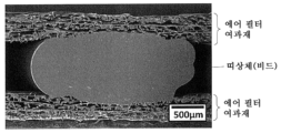
상기 제작한 에어 필터 여과재에 대하여 도 12의 방법을 실시하고, 폭 방향의 양쪽의 단부(11)에 비드인 띠상체(7)를 구비한 도 5a 내지 도 5c에 도시한 필터 플리트 팩(1)(폭 50㎜, 길이 100㎜, 플리트 높이 H0 15㎜, 플리트수 5개/㎝)을 얻었다. 플리트 가공에는, 레시프로식 플리트 머신을 사용하였다. 제1 프로세스에 있어서 도포하는 수지(41)의 도포폭은 1.5㎜로 하고, 도포 온도는 160℃로 하였다. 수지(41)의 도포는, 에어 필터 여과재에서의 한쪽의 통기성 지지층의 표면에 대하여 실시하였다. 수지(41)에는, 핫 멜트 수지(Henkel사 제조, 테크노 멜트 AS3115)를 사용하였다. 제작한 필터 플리트 팩에서의 띠상체(7) 및 그 근방에 대한 SEM에 의한 관찰 상(像)을 도 18에 도시한다. 도 18의 관찰 상에는, 띠상체(7)의 부분 X를 기류(14)의 방향을 따라서 본 단면 Y가 도시되어 있다. 도 18에 도시한 바와 같이, 띠상체(7)는 띠상체(7)가 접하는 양쪽의 플리트면(26A, 26B)에 있어서, 수지(41)를 도포한 통기성 지지층에 침투하여 PTFE 다공질막에 도달되어 있었다. 도 18의 관찰 상을 포함하는 3개의 관찰 상으로부터 평가한 띠상체(7)의 폭 W0은 3.0㎜, 폭 W1은 2.3㎜, 비 W1/W0은 0.77, 종횡비 H0/W0은 0.43이었다. 또한, 도 18의 관찰 상에 도시한 띠상체(7)의 한쪽 측면은 오목부를 갖고 있지 않았다.A filter pleat pack (1) shown in FIGS. 5A to 5C in which the method of FIG. 12 was applied to the air filter material produced above and provided with bead-
다음으로, 제작한 필터 플리트 팩을, 띠상체(7)의 형성면이 기류(19)의 하류측이 되도록 프레임체에 끼워넣고, 필터 플리트 팩의 폭 방향의 양쪽 단부에서의 측면과 프레임체의 간극에 기류(19)의 하류측으로부터 핫 멜트 수지를 유입하고, 필터 플리트 팩과 프레임체를 상기 단부에서의 하류측의 영역에서만 접합하여, 도 17a 및 도 17b에 도시한 에어 필터 유닛을 얻었다. 제작한 에어 필터 유닛의 포집 효율을 상술한 방법(상류측 입자 농도는 1.0×10⁸개/L)에 의해 평가한바, 99.99% 이상이었다.Next, the fabricated filter pleat pack is inserted into the frame body so that the formation surface of the band-
(실시예 2)(Example 2)
수지(41)의 도포 온도를 150℃, 도포폭을 2.5㎜로 변경한 것 이외에는 실시예 1과 마찬가지로 하여, 도 5a 내지 도 5c에 도시한 필터 플리트 팩, 및 도 17a 및 도 17b에 도시한 에어 필터 유닛을 얻었다. 제작한 필터 플리트 팩에서의 띠상체(7) 및 그 근방에 대한 SEM에 의한 관찰 상을 도 19에 도시한다. 도 19의 관찰 상에는, 띠상체(7)의 부분 X를 기류(14)의 방향을 따라서 본 단면 Y가 도시되어 있다. 도 19에 도시한 바와 같이, 띠상체(7)는 띠상체(7)가 접하는 양쪽의 플리트면(26A, 26B)에 있어서, 수지(41)를 도포한 통기성 지지층에 침투하여 PTFE 다공질막에 도달되어 있었다. 도 19의 관찰 상을 포함하는 3개의 관찰 상으로부터 평가한 띠상체(7)의 폭 W0은 5.0㎜, 폭 W1은 4.0㎜, 비 W1/W0은 0.8, 종횡비 H0/W0은 0.23이었다. 또한, 도 19의 관찰 상에 도시한 띠상체(7)의 한쪽 측면은 오목부를 갖고 있지 않았다. 제작한 에어 필터 유닛의 포집 효율을 상술한 방법에 의해 평가한바, 99.99% 이상이었다.Filter pleat packs shown in FIGS. 5A to 5C and air shown in FIGS. 17A and 17B in the same manner as in Example 1 except that the application temperature of the
(실시예 3)(Example 3)
수지(41)의 도포폭을 2.5㎜로 변경한 것 이외에는 실시예 1과 마찬가지로 하여, 도 5a 내지 도 5c에 도시한 필터 플리트 팩, 그리고 도 17a 및 도 17b에 도시한 에어 필터 유닛을 얻었다. 제작한 필터 플리트 팩에서의 띠상체(7) 및 그 근방에 대한 SEM에 의한 관찰 상을 도 20a 및 도 20b에 나타낸다. 도 20a의 관찰 상에는, 띠상체(7)의 부분 X를 기류(14)의 방향을 따라서 본 단면 Y가 도시되어 있다. 도 20b에는, 도 20a의 관찰 상에 있어서 띠상체(7)와 에어 필터 여과재(2)가 접하고 있는 부분의 확대상이 도시되어 있다. 도 20a 및 도 20b에 도시한 바와 같이, 띠상체(7)는 띠상체(7)가 접하는 양쪽의 플리트면(26A, 26B)에 있어서, 수지(41)를 도포한 통기성 지지층에 침투하여 PTFE 다공질막에 도달되어 있었다. 도 20a의 관찰 상을 포함하는 3개의 관찰 상으로부터 평가한 띠상체(7)의 폭 W0은 7.0㎜, 폭 W1은 6.0㎜, 비 W1/W0은 0.86, 종횡비 H0/W0은 0.15이었다. 또한, 도 20a의 관찰 상에 도시한 띠상체(7)의 양쪽 측면은 오목부를 갖고 있지 않았다. 제작한 에어 필터 유닛의 포집 효율을 상술한 방법에 의해 평가한바, 99.99% 이상이었다.Filter pleat packs shown in Figs. 5A to 5C and air filter units shown in Figs. 17A and 17B were obtained in the same manner as in Example 1 except that the application width of the
(비교예 1)(Comparative Example 1)
수지(41)의 도포 온도를 140℃로 변경한 것 이외에는 실시예 1과 마찬가지로 하여, 필터 플리트 팩 및 에어 필터 유닛을 얻었다. 제작한 필터 플리트 팩에서의 띠상체 및 그 근방에 대한 SEM에 의한 관찰 상을 도 21a 및 도 21b에 나타낸다. 도 21a의 관찰 상에는, 띠상체의 부분 X를 기류(14)의 방향을 따라서 본 단면 Y가 도시되어 있다. 도 21b에는, 도 21a의 관찰 상에 있어서 띠상체와 에어 필터 여과재(2)가 접하고 있는 부분의 확대상이 도시되어 있다. 도 21a 및 도 21b에 도시한 바와 같이, 띠상체는, 수지(41)를 도포한 통기성 지지층에는 침투하고 있었지만, PTFE 다공질막에는 도달하고 있지 않았다. 또한, 도 21a의 관찰 상에 도시한 띠상체는, 먼저 도포된 수지(41A)에서 유래되는 부분이며 도포 시의 형상을 거의 유지한 부분과, 후에 도포된 수지(41B)에서 유래되는 부분이며 도포 시의 형상으로부터 크게 변형된 부분이 접합한 형상을 갖고 있었다. 제작한 에어 필터 유닛의 포집 효율을 상술한 방법에 의해 평가한바, 99.9%였다.A filter pleat pack and an air filter unit were obtained in the same manner as in Example 1 except that the application temperature of the
(비교예 2)(Comparative Example 2)
수지(41)의 도포 온도를 150℃로, 도포폭을 1.0㎜로 변경한 것 이외에는 실시예 1과 마찬가지로 하여, 필터 플리트 팩 및 에어 필터 유닛을 얻었다. 제작한 필터 플리트 팩에서의 띠상체 및 그 근방에 대한 SEM에 의한 관찰 상을 도 22a 및 도 22b에 나타낸다. 도 22a의 관찰 상에는, 띠상체의 부분 X를 기류(14)의 방향을 따라서 본 단면 Y가 도시되어 있다. 도 22b에는, 도 22a의 관찰 상에 있어서 띠상체와 에어 필터 여과재(2)가 접하고 있는 부분의 확대상이 도시되어 있다. 도 22a 및 도 22b에 도시한 바와 같이, 띠상체는, 수지(41)를 도포한 통기성 지지층에는 침투하고 있었지만, PTFE 다공질막에는 도달하고 있지 않았다. 또한, 도 22a의 관찰 상에 도시한 띠상체는, 먼저 도포된 수지(41A)에서 유래되는 부분이며 도포 시의 형상을 거의 유지한 부분과, 후에 도포된 수지(41B)에서 유래되는 부분이며 도포 시의 형상으로부터 크게 변형된 부분이 접합한 형상을 갖고 있었다. 제작한 에어 필터 유닛의 포집 효율을 상술한 방법에 의해 평가한바, 99.9%였다.A filter pleat pack and an air filter unit were obtained in the same manner as in Example 1 except that the application temperature of the
(참고예)(Reference example)
비교예 1에서 제작한 필터 플리트 팩을, 띠상체의 형성면이 하류측이 되도록 프레임체(폭 50㎜ 및 길이 100㎜의 직사각형의 개구를 가짐)에 집어넣고, 필터 플리트 팩의 폭 방향의 단부 측면 전체에 핫 멜트 수지를 도포함으로써 필터 플리트 팩과 프레임체를 접합하여, 에어 필터 유닛을 얻었다. 제작한 에어 필터 유닛의 포집 효율을 상술한 방법에 의해 평가한바, 99.99% 이상이었다.The filter pleat pack produced in Comparative Example 1 was put into a frame body (having a rectangular opening with a width of 50 mm and a length of 100 mm) so that the band-shaped body formation surface was on the downstream side, and the end of the filter pleat pack in the width direction By applying hot melt resin to the entire side surface, the filter pleat pack and the frame were joined to obtain an air filter unit. The collection efficiency of the fabricated air filter unit was evaluated by the method described above and was 99.99% or more.
각 예에서의 수지(41)의 도포 조건 및 에어 필터 유닛의 포집 효율을 이하의 표 1에 정리한다.The application conditions of the

표 1에 나타낸 바와 같이, 실시예에서는, 필터 플리트 팩의 폭 방향의 단부 측면 전체에 핫 멜트 수지를 도포하여 프레임체와 접합한 참고예와 동등한 포집 효율을 유지할 수 있었지만, 비교예에서는, 참고예에 비하여 포집 효율이 저하되었다. 비교예에서의 포집 효율의 저하는, 필터 플리트 팩의 폭 방향의 단부 측면과 프레임체 사이의 간극을 통한 사이드 누설에 기인한다고 생각되었다.As shown in Table 1, in the examples, the hot melt resin was applied to the entire widthwise end side of the filter pleat pack to maintain the same collection efficiency as the reference example bonded to the frame body, but in the comparative example, the reference example Compared to that, the collection efficiency was lowered. It was considered that the decrease in collection efficiency in Comparative Example was due to side leakage through a gap between the frame body and the end side surface in the width direction of the filter pleat pack.
본 발명의 필터 플리트 팩은, 종래의 필터 플리트 팩과 마찬가지의 용도로 사용할 수 있다. 용도의 예는, 에어 필터 유닛이다.The filter pleat pack of the present invention can be used for the same purpose as the conventional filter pleat pack. An example of the application is an air filter unit.
Claims (20)
상기 에어 필터 여과재는, 제1 불소 수지 다공질막과, 제1 통기성 지지층을 구비하고,
상기 제1 통기성 지지층은,
상기 제1 불소 수지 다공질막에 대하여, 상기 에어 필터 여과재를 투과하는 기류 M의 하류측에 배치되며, 또한
폭 방향의 적어도 한쪽의 단부에, 상기 단부를 따라 연장됨과 함께, 상기 제1 통기성 지지층에서의 상기 폭 방향의 통기를 저해하는 통기 저해부를 갖고,
상기 통기 저해부는, 상기 제1 불소 수지 다공질막에 접하고 있는, 필터 플리트 팩.
단, 상기 폭 방향은, 상기 플리트상으로 접힌 에어 필터 여과재의 플리트선이 연장되는 방향이다.A filter pleat pack including air filter filter media folded into a pleat shape,
The air filter material includes a first porous fluororesin film and a first breathable support layer;
The first breathable support layer,
It is disposed on the downstream side of the airflow M passing through the air filter material with respect to the first fluororesin porous membrane, and
At least one end portion in the width direction has a ventilation blocking portion extending along the end portion and inhibiting ventilation in the width direction in the first air permeability support layer;
The filter pleat pack according to claim 1 , wherein the ventilation blocking portion is in contact with the first porous fluororesin film.
However, the width direction is a direction in which pleat lines of the air filter filter material folded into the pleat shape extend.
상기 통기 저해부는, 상기 제1 통기성 지지층에서의 상기 제1 불소 수지 다공질막 측과는 반대 측에 위치하는 제1 표면에 도달되어 있는, 필터 플리트 팩.According to claim 1,
The filter pleat pack according to claim 1 , wherein the ventilation-blocking portion reaches a first surface located on a side opposite to the side of the first porous fluororesin film in the first air permeability support layer.
상기 제1 통기성 지지층은, 상기 폭 방향의 양쪽 단부의 각각에 상기 통기 저해부를 갖는, 필터 플리트 팩.According to claim 1 or 2,
The filter pleat pack of claim 1 , wherein the first air permeability support layer has the air permeability blocking portion at each of both end portions in the width direction.
상기 적어도 한쪽의 단부에 있어서, 상기 제1 통기성 지지층에는 제1 수지가 침투하고 있으며,
상기 통기 저해부는, 상기 제1 통기성 지지층에서의 상기 제1 수지가 침투한 부분을 포함하는, 필터 플리트 팩.According to any one of claims 1 to 3,
In the at least one end portion, a first resin permeates the first air permeable support layer,
The filter pleat pack of claim 1 , wherein the ventilation-blocking portion includes a portion of the first breathable support layer into which the first resin penetrates.
상기 적어도 한쪽의 단부에 있어서, 상기 제1 통기성 지지층은 열 융착 가공되어 있으며,
상기 통기 저해부는, 상기 제1 통기성 지지층에서의 상기 열 융착 가공이 이루어진 부분을 포함하는, 필터 플리트 팩.According to any one of claims 1 to 4,
At the at least one end portion, the first breathable support layer is thermally fused,
The filter pleat pack of claim 1 , wherein the ventilation-blocking portion includes a portion subjected to the heat-sealing process in the first air permeability support layer.
상기 필터 플리트 팩은, 상기 필터 플리트 팩에서의 상기 폭 방향의 적어도 한쪽의 단부에, 당해 단부를 따라 연장하는 띠상체를 갖고,
상기 띠상체는,
제1 수지를 포함하며, 또한
상기 에어 필터 여과재에서의 상기 제1 통기성 지지층 측에 위치하는 제2 표면에 배치됨과 함께, 상기 제1 불소 수지 다공질막에 도달하도록 상기 제2 표면으로부터 상기 제1 통기성 지지층의 내부에 침투하고 있으며,
상기 통기 저해부는, 상기 제1 통기성 지지층에서의 상기 띠상체가 침투한 부분을 포함하는, 필터 플리트 팩.According to any one of claims 1 to 3,
The filter pleat pack has a band-like body extending along at least one end portion in the width direction of the filter pleat pack, and
The band-shaped body,
It includes a first resin, and
It is disposed on a second surface located on the side of the first air permeable support layer in the air filter material, and penetrates into the first air permeable support layer from the second surface so as to reach the first fluororesin porous film,
The filter pleat pack of claim 1 , wherein the ventilation-blocking portion includes a portion of the first air permeability support layer into which the band-like body penetrates.
상기 띠상체에서의, 상기 접힌 에어 필터 여과재의 상류측의 골접힘선과, 상기 에어 필터 여과재를 따라 상기 상류측의 골접힘선에 인접한 2개의 하류측의 골접힘선에 접하는 면의 사이에 위치하는 부분을, 상기 필터 플리트 팩을 투과하는 기류 P가 향하는 방향을 따라서 본 단면에 있어서, 비 W1/W0이 0.6 이상인, 필터 플리트 팩.
단, W0은, 상기 단면에서의 상기 띠상체의 상기 폭 방향의 길이이며, W1은, 상기 단면에 있어서, 상기 띠상체가 상기 제1 불소 수지 다공질막과 접하는 부분의 상기 폭 방향의 길이이다.According to claim 6,
located between a surface in the band-shaped body in contact with an upstream bone fold line of the folded air filter material and two downstream bone fold lines adjacent to the upstream bone fold line along the air filter filter material The filter pleat pack according to claim 1 , wherein the ratio W 1 /W 0 is 0.6 or more in a section view of the portion along the direction of the airflow P passing through the filter pleat pack.
Here, W 0 is the length in the width direction of the band-like body in the cross section, and W 1 is the length in the width direction of the portion where the band-shaped body contacts the first fluororesin porous film in the cross section. am.
상기 띠상체에서의, 상기 접힌 에어 필터 여과재의 상류측의 골접힘선과, 상기 에어 필터 여과재에 따라 상기 상류측의 골접힘선에 인접한 2개의 하류측의 골접힘선에 접하는 면의 사이에 위치하는 부분을, 상기 필터 플리트 팩을 투과하는 기류 P가 향하는 방향을 따라서 본 단면에 있어서, 상기 띠상체의 상기 제1 불소 수지 다공질막과 접하는 부분의 상기 폭 방향의 길이 W1이 1.0㎜ 이상인, 필터 플리트 팩.According to claim 6 or 7,
Located between a surface in the band-like body in contact with an upstream bone fold line of the folded air filter material and two downstream bone fold lines adjacent to the upstream bone fold line along the air filter filter material In a section view of the portion along the direction of the airflow P passing through the filter pleat pack, the length W 1 in the width direction of the portion in contact with the first fluororesin porous film of the band-shaped body is 1.0 mm or more. Fleet Pack.
상기 띠상체는, 상기 필터 플리트 팩의 비드인, 필터 플리트 팩.According to any one of claims 6 to 8,
The band-like body is a bead of the filter pleat pack.
상기 제1 수지는 핫 멜트 수지인, 필터 플리트 팩.The method of any one of claims 4 and 6 to 8,
The first resin is a hot melt resin, filter pleat pack.
상기 필터 플리트 팩에서의 상기 폭 방향의 단부이며, 상기 제1 통기성 지지층이 상기 통기 저해부를 갖고 있는 적어도 하나의 단부를 상기 폭 방향을 따라 보았을 때에, 상기 기류 M의 하류측에 있어서 대향하는 상기 에어 필터 여과재 사이의 영역을 충전하도록 제2 수지가 배치되어 있는, 필터 플리트 팩.According to any one of claims 1 to 10,
The air that faces at least one end portion of the filter pleat pack in the width direction and at least one end portion in which the first air permeability support layer has the ventilation blocking portion is opposed on the downstream side of the air flow M when viewed along the width direction. A filter pleat pack, wherein a second resin is disposed so as to fill a region between filter media.
상기 필터 플리트 팩에서의 상기 폭 방향의 단부이며, 상기 제1 통기성 지지층이 상기 통기 저해부를 갖고 있는 적어도 하나의 단부를 상기 폭 방향을 따라 보았을 때에, 상기 제2 수지는, 상기 필터 플리트 팩을 투과하는 기류 P에 대하여 상류측에 위치하는 골접힘선에서 골접힘선간 높이의 50% 이상의 범위에 이르기까지, 상기 영역을 충전하도록 배치되어 있는, 필터 플리트 팩.According to claim 11,
When at least one end portion of the filter pleat pack in the width direction and at which the first air permeability support layer has the ventilation blocking portion is viewed along the width direction, the second resin penetrates the filter pleat pack. A filter pleat pack arranged so as to fill the region from a bone fold line located on the upstream side of the airflow P to a range of 50% or more of the height between the bone fold lines.
상기 제2 수지는 핫 멜트 수지인, 필터 플리트 팩.According to claim 11 or 12,
The second resin is a hot melt resin, filter pleat pack.
상기 에어 필터 여과재는, 제2 통기성 지지층을 더 구비하고,
상기 제1 불소 수지 다공질막은, 상기 제1 통기성 지지층 및 상기 제2 통기성 지지층에 의해 끼워져 지지되어 있는, 필터 플리트 팩.According to any one of claims 1 to 13,
The air filter material further includes a second breathable support layer,
The filter pleat pack wherein the first fluororesin porous film is sandwiched and supported by the first air permeability support layer and the second air permeability support layer.
상기 에어 필터 여과재는, 제2 불소 수지 다공질막을 더 구비하고,
상기 제1 불소 수지 다공질막은, 상기 에어 필터 여과재가 구비하는 모든 불소 수지 다공질막 중, 상기 기류 M에 대하여 가장 하류측에 위치하는, 필터 플리트 팩.According to any one of claims 1 to 14,
The air filter material further includes a second porous fluororesin film,
The filter pleat pack wherein the first porous fluororesin membrane is located most downstream with respect to the air flow M among all the porous fluororesin membranes included in the air filter material.
상기 제1 불소 수지 다공질막이 폴리테트라플루오로에틸렌 다공질막인, 필터 플리트 팩.According to any one of claims 1 to 15,
The filter pleat pack in which the said 1st fluororesin porous film is a polytetrafluoroethylene porous film.
상기 필터 플리트 팩이, 제1항 내지 제16항 중 어느 한 항에 기재된 필터 플리트 팩인, 에어 필터 유닛.An air filter unit comprising a filter pleat pack and a frame supporting the filter pleat pack,
The air filter unit, wherein the filter pleat pack is the filter pleat pack according to any one of claims 1 to 16.
상기 필터 플리트 팩에서의 상기 폭 방향의 단부이며, 상기 제1 통기성 지지층이 상기 통기 저해부를 갖고 있는 적어도 하나의 단부는, 당해 단부에서의 상기 에어 필터 유닛을 투과하는 기류 F의 하류측의 영역에서, 상기 프레임체와 접합되어 있는, 에어 필터 유닛.According to claim 17,
At least one end of the filter pleat pack in the width direction, at which the first air permeability support layer has the ventilation blocking portion, is in a region on the downstream side of the airflow F passing through the air filter unit at the end. , The air filter unit joined to the frame body.
상기 적어도 하나의 단부에서의 상기 기류 F의 상류측의 영역은 상기 프레임체와 접합되어 있지 않은, 에어 필터 유닛.According to claim 18,
The air filter unit of claim 1 , wherein a region on an upstream side of the air flow F at the at least one end portion is not joined to the frame body.
상기 프레임체는, 상기 필터 플리트 팩에서의 상기 폭 방향의 단부이며, 상기 제1 통기성 지지층이 상기 통기 저해부를 갖고 있는 단부 측의 측면을 덮는 형상을 갖는, 에어 필터 유닛.According to any one of claims 17 to 19,
The air filter unit according to claim 1 , wherein the frame body is an end portion of the filter pleat pack in the width direction and has a shape covering a side surface of an end side where the first air permeability support layer has the ventilation blocking portion.
Applications Claiming Priority (3)
| Application Number | Priority Date | Filing Date | Title |
|---|---|---|---|
| JP2020179754 | 2020-10-27 | ||
| JPJP-P-2020-179754 | 2020-10-27 | ||
| PCT/JP2021/039689 WO2022092161A1 (en) | 2020-10-27 | 2021-10-27 | Filter pleat pack, and air filter unit |
Publications (1)
| Publication Number | Publication Date |
|---|---|
| KR20230097097A true KR20230097097A (en) | 2023-06-30 |
Family
ID=81382644
Family Applications (1)
| Application Number | Title | Priority Date | Filing Date |
|---|---|---|---|
| KR1020237017664A KR20230097097A (en) | 2020-10-27 | 2021-10-27 | Filter pleat pack and air filter unit |
Country Status (6)
| Country | Link |
|---|---|
| US (1) | US20230390686A1 (en) |
| EP (1) | EP4238635A1 (en) |
| JP (1) | JPWO2022092161A1 (en) |
| KR (1) | KR20230097097A (en) |
| CN (1) | CN116457070A (en) |
| WO (1) | WO2022092161A1 (en) |
Citations (1)
| Publication number | Priority date | Publication date | Assignee | Title |
|---|---|---|---|---|
| JP2014198313A (en) | 2013-03-29 | 2014-10-23 | 日東電工株式会社 | Filter medium and method of manufacturing filter medium |
Family Cites Families (10)
| Publication number | Priority date | Publication date | Assignee | Title |
|---|---|---|---|---|
| JPH0889737A (en) * | 1994-09-28 | 1996-04-09 | Japan Vilene Co Ltd | Filter |
| JP3127771B2 (en) * | 1995-03-31 | 2001-01-29 | 東レ株式会社 | Filter unit |
| JPH10156121A (en) * | 1996-12-04 | 1998-06-16 | Matsushita Seiko Co Ltd | Filter of air cleaner |
| JP2002058943A (en) * | 2000-08-14 | 2002-02-26 | Bridgestone Corp | Filter and its manufacturing method |
| JP2013022547A (en) * | 2011-07-25 | 2013-02-04 | Nitto Denko Corp | Filter unit and cleaner provided with the same |
| US20150096933A1 (en) * | 2013-10-07 | 2015-04-09 | W. L. Gore & Associates, Inc. | Filtration Article Having Thermoplastic Filled Edges |
| JP6647553B2 (en) * | 2016-03-01 | 2020-02-14 | Smc株式会社 | Filter element |
| JP2019531880A (en) * | 2016-08-26 | 2019-11-07 | スリーエム イノベイティブ プロパティズ カンパニー | Pleated filter element with pleated filter media having an edge dam and method of making and using the same |
| US11338233B2 (en) * | 2017-09-22 | 2022-05-24 | Nitto Denko Corporation | Air filter medium, filter pleat pack, and air filter unit |
| JP2020093197A (en) * | 2018-12-11 | 2020-06-18 | トヨタ紡織株式会社 | Filter element and method of manufacturing the same |
-
2021
- 2021-10-27 WO PCT/JP2021/039689 patent/WO2022092161A1/en active Application Filing
- 2021-10-27 JP JP2022559207A patent/JPWO2022092161A1/ja active Pending
- 2021-10-27 KR KR1020237017664A patent/KR20230097097A/en unknown
- 2021-10-27 US US18/033,113 patent/US20230390686A1/en active Pending
- 2021-10-27 EP EP21886278.7A patent/EP4238635A1/en active Pending
- 2021-10-27 CN CN202180072863.8A patent/CN116457070A/en active Pending
Patent Citations (1)
| Publication number | Priority date | Publication date | Assignee | Title |
|---|---|---|---|---|
| JP2014198313A (en) | 2013-03-29 | 2014-10-23 | 日東電工株式会社 | Filter medium and method of manufacturing filter medium |
Also Published As
| Publication number | Publication date |
|---|---|
| JPWO2022092161A1 (en) | 2022-05-05 |
| WO2022092161A1 (en) | 2022-05-05 |
| EP4238635A1 (en) | 2023-09-06 |
| CN116457070A (en) | 2023-07-18 |
| US20230390686A1 (en) | 2023-12-07 |
Similar Documents
| Publication | Publication Date | Title |
|---|---|---|
| TWI503163B (en) | Teflon porous film and air filter filter | |
| KR102390248B1 (en) | Air filter media, filter pleat packs and air filter units | |
| JP5051944B2 (en) | Filter material for air filter and manufacturing method thereof | |
| TWI783949B (en) | Air filter material, air filter group and air filter unit | |
| KR102255737B1 (en) | Method for producing air filter material, air filter material, and air filter pack | |
| TWI601567B (en) | Filter medium and filter unit | |
| JP2007160275A (en) | Filter unit and its manufacturing method | |
| EP3804832A1 (en) | Filter medium and filter unit including same | |
| TW201420167A (en) | Filter material and method for manufacturing filter material | |
| KR20230097097A (en) | Filter pleat pack and air filter unit | |
| JP7405837B2 (en) | Filter media and filter unit | |
| US20230356152A1 (en) | Air filter medium, filter pleat pack, and air filter unit | |
| US20230364547A1 (en) | Air filter medium, filter pleat pack, and air filter unit | |
| CN113272038B (en) | Filter pleat pack and air filter unit | |
| CN113260443B (en) | Filter pleat pack and air filter unit | |
| WO2022065517A1 (en) | Air filter filtering medium, filter pleat pack, and air filter unit |