KR20230081721A - Application of additives from the radial outside in the production of aerosol-generating rods - Google Patents
Application of additives from the radial outside in the production of aerosol-generating rods Download PDFInfo
- Publication number
- KR20230081721A KR20230081721A KR1020237015486A KR20237015486A KR20230081721A KR 20230081721 A KR20230081721 A KR 20230081721A KR 1020237015486 A KR1020237015486 A KR 1020237015486A KR 20237015486 A KR20237015486 A KR 20237015486A KR 20230081721 A KR20230081721 A KR 20230081721A
- Authority
- KR
- South Korea
- Prior art keywords
- additive
- susceptor
- forming space
- converging device
- supply line
- Prior art date
Links
Images


Classifications
-
- A—HUMAN NECESSITIES
- A24—TOBACCO; CIGARS; CIGARETTES; SIMULATED SMOKING DEVICES; SMOKERS' REQUISITES
- A24C—MACHINES FOR MAKING CIGARS OR CIGARETTES
- A24C5/00—Making cigarettes; Making tipping materials for, or attaching filters or mouthpieces to, cigars or cigarettes
- A24C5/01—Making cigarettes for simulated smoking devices
-
- A—HUMAN NECESSITIES
- A24—TOBACCO; CIGARS; CIGARETTES; SIMULATED SMOKING DEVICES; SMOKERS' REQUISITES
- A24C—MACHINES FOR MAKING CIGARS OR CIGARETTES
- A24C5/00—Making cigarettes; Making tipping materials for, or attaching filters or mouthpieces to, cigars or cigarettes
- A24C5/14—Machines of the continuous-rod type
- A24C5/18—Forming the rod
- A24C5/1807—Forming the rod with compressing means, e.g. garniture
-
- A—HUMAN NECESSITIES
- A24—TOBACCO; CIGARS; CIGARETTES; SIMULATED SMOKING DEVICES; SMOKERS' REQUISITES
- A24C—MACHINES FOR MAKING CIGARS OR CIGARETTES
- A24C5/00—Making cigarettes; Making tipping materials for, or attaching filters or mouthpieces to, cigars or cigarettes
- A24C5/14—Machines of the continuous-rod type
- A24C5/18—Forming the rod
- A24C5/1892—Forming the rod with additives, e.g. binding agent, flavorants
-
- A—HUMAN NECESSITIES
- A24—TOBACCO; CIGARS; CIGARETTES; SIMULATED SMOKING DEVICES; SMOKERS' REQUISITES
- A24D—CIGARS; CIGARETTES; TOBACCO SMOKE FILTERS; MOUTHPIECES FOR CIGARS OR CIGARETTES; MANUFACTURE OF TOBACCO SMOKE FILTERS OR MOUTHPIECES
- A24D1/00—Cigars; Cigarettes
- A24D1/20—Cigarettes specially adapted for simulated smoking devices
-
- A—HUMAN NECESSITIES
- A24—TOBACCO; CIGARS; CIGARETTES; SIMULATED SMOKING DEVICES; SMOKERS' REQUISITES
- A24F—SMOKERS' REQUISITES; MATCH BOXES; SIMULATED SMOKING DEVICES
- A24F40/00—Electrically operated smoking devices; Component parts thereof; Manufacture thereof; Maintenance or testing thereof; Charging means specially adapted therefor
- A24F40/40—Constructional details, e.g. connection of cartridges and battery parts
- A24F40/46—Shape or structure of electric heating means
- A24F40/465—Shape or structure of electric heating means specially adapted for induction heating
-
- H—ELECTRICITY
- H05—ELECTRIC TECHNIQUES NOT OTHERWISE PROVIDED FOR
- H05B—ELECTRIC HEATING; ELECTRIC LIGHT SOURCES NOT OTHERWISE PROVIDED FOR; CIRCUIT ARRANGEMENTS FOR ELECTRIC LIGHT SOURCES, IN GENERAL
- H05B6/00—Heating by electric, magnetic or electromagnetic fields
- H05B6/02—Induction heating
- H05B6/10—Induction heating apparatus, other than furnaces, for specific applications
- H05B6/105—Induction heating apparatus, other than furnaces, for specific applications using a susceptor
Abstract
에어로졸 발생 로드를 생산하기 위한 장치는 수렴 장치, 서셉터 가이드, 및 컨베이어 시스템을 포함하고 있다. 수렴 장치는 축 방향을 따라 수렴하는 형성 공간을 갖는다. 서셉터 가이드는 수렴 장치의 형성 공간 내로 연장되어 있고, 수렴 장치의 형성 공간 내부에 서셉터를 위한 출구 개구부를 포함하고 있다. 컨베이어 시스템은, 바람직하게는 시트로서 형성된 충진 물질을 수렴 장치의 형성 공간을 통해 운반하여 충진 물질을 서셉터를 포함하는 로드로 형상화하도록 구성되어 있다. 장치는, 서셉터 가이드의 반경방향 외측에 있는 수렴 장치의 형성 공간 내로 개방되는 분배 개구부를 갖는 적어도 하나의 첨가제 공급 라인을 더 포함하고 있다.An apparatus for producing an aerosol-generating rod includes a converging device, a susceptor guide, and a conveyor system. The converging device has a forming space converging along an axial direction. The susceptor guide extends into the forming space of the converging device and comprises an outlet opening for the susceptor inside the forming space of the converging device. The conveyor system is configured to convey the filling material, preferably formed as a sheet, through the forming space of the converging device to shape the filling material into a rod comprising a susceptor. The device further comprises at least one additive supply line having a dispensing opening opening into the forming space of the converging device radially outside the susceptor guide.
Description
본 개시는 특히 에어로졸 발생 물품 생산에 사용하기 위한, 특히 소비자 제품용, 에어로졸 발생 로드에 관한 것이다.The present disclosure relates to aerosol-generating rods, particularly for use in producing aerosol-generating articles, particularly for consumer products.
특히, 본 개시는 가열 가능한 서셉터를 포함하는 로드로 형성되는 충진 물질에 첨가제를 적용하는 것에 관한 것이다.In particular, the present disclosure relates to the application of additives to a fill material formed into a rod comprising a heatable susceptor.
에어로졸 발생 물품의 생산에 사용하기 위한 로드를 얻기 위해 형상화 장치로 시트 물질을 재형상화하는 것이 실제로 공지되어 있다. 로드는 서셉터를 교번 자기장에 가함으로써 열을 발생시킬 수 있도록 서셉터를 그 안에 포함할 수 있다. 이는 로드를 내부로부터 가열하여 로드로부터 방출 에어로졸을 야기하게 한다.It is known in practice to reshape sheet material with shaping devices to obtain rods for use in the production of aerosol-generating articles. The rod may contain a susceptor therein so that heat can be generated by subjecting the susceptor to an alternating magnetic field. This heats the rod from the inside causing an ejection aerosol from the rod.
에어로졸 발생 로드의 생산 시 하나 이상의 물질을 첨가할 수 있게 하는 것이 바람직할 수 있다. 예를 들어, 에어로졸 발생 물질 또는 향미 물질을 로드에 첨가하는 것이 바람직할 수 있다. 하나 이상의 물질을 첨가함으로써 로드의 특성을 변경하는 효율적인 방법을 제공하는 것이 바람직할 수 있다. 로드 내부에서 하나 이상의 물질의 양호한 분포를 수득하는 방법을 제공하는 것이 바람직할 수 있다.It may be desirable to be able to add one or more substances in the production of an aerosol-generating rod. For example, it may be desirable to add an aerosol generating substance or flavoring substance to the rod. It may be desirable to provide an efficient method of altering the properties of a rod by adding one or more substances. It may be desirable to provide a method to obtain a good distribution of one or more substances within the rod.
본 발명의 하나의 측면에 따르면, 에어로졸 발생 로드를 생산하기 위한 장치가 제공되어 있다. 장치는 수렴 장치, 서셉터 가이드, 컨베이어 시스템 및 적어도 하나의 첨가제 공급 라인을 포함하고 있다. 수렴 장치는 축 방향을 따라 수렴하는 형성 공간을 갖는다. 서셉터 가이드는 수렴 장치의 형성 공간 내로 연장되어 있다. 서셉터 가이드는 수렴 장치의 형성 공간 내부에 서셉터용 출구 개구부를 포함하고 있다. 컨베이어 시스템은, 충진 물질을 수렴 장치의 형성 공간을 통해 운반하여 충진 물질을 서셉터를 포함하는 로드로 형상화하도록 구성되어 있다. 적어도 하나의 첨가제 공급 라인은 서셉터 가이드의 반경방향 외측에 있는 수렴 장치의 형성 공간 내로 개방되는 분배(dispensing) 개구부를 갖는다.According to one aspect of the present invention, an apparatus for producing an aerosol-generating rod is provided. The device includes a converging device, a susceptor guide, a conveyor system and at least one additive supply line. The converging device has a forming space converging along an axial direction. The susceptor guide extends into the forming space of the converging device. The susceptor guide includes an exit opening for the susceptor inside the forming space of the converging device. The conveyor system is configured to convey the fill material through the forming space of the converging device to shape the fill material into a rod comprising a susceptor. At least one additive supply line has a dispensing opening opening into the forming space of the converging device radially outside the susceptor guide.
수렴 장치의 형성 공간 내로 개방되는 그의 분배 개구부를 갖는 적어도 하나의 첨가제 공급 라인은 수렴 장치의 형성 공간 내부에 첨가제를 분배할 수 있게 한다. 수렴 장치의 형성 공간 내부에 첨가제를 분배하는 것은, 분배된 첨가제 또는 분배된 첨가제의 전부의 높은 백분율, 특히 적어도 95%가 로드 내에 실제로 통합되도록 보장함으로써, 첨가제에 의한 첨가제의 폐기물 및 장비의 오염을 감소시킬 수 있다. 첨가제는, 수렴 장치 내에서 충진 물질이 형상화되는 동안 충진 물질 상에 분배될 수 있으므로, 충진 물질 위로의 첨가제의 분포가 용이해질 수 있다.At least one additive supply line having its dispensing opening opening into the forming space of the converging device makes it possible to distribute the additive inside the forming space of the converging device. Dispensing the additive inside the forming space of the converging device ensures that a high percentage, in particular at least 95%, of the additive dispensed or all of the additive dispensed is actually incorporated into the rod, thereby reducing waste of the additive and contamination of the equipment by the additive. can reduce Additives can be dispensed on the fill material while it is being shaped in the converging device, thereby facilitating distribution of the additive onto the fill material.
최종 로드 내부에서의 첨가제의 분포는, 예를 들어 수렴 장치의 형성 공간 내부에서 분배 개구부의 정확한 위치를 적절하게 선택함으로써 영향을 받을 수 있다.The distribution of the additive inside the final rod can be influenced, for example, by properly choosing the exact position of the dispensing opening inside the forming space of the converging device.
상기 분배 개구부를 통해 상기 서셉터 가이드의 반경방향 외측에 있는 상기 수렴 장치의 형성 공간 내로 상기 첨가제를 분배하는 것은 상기 로드에서 상기 첨가제의 양호한 분포를 얻는 것을 용이하게 할 수 있다. 특히, 충진 물질 위로의 첨가제의 균질한 분포가 용이해질 수 있다. 분배 개구부가 서셉터 가이드의 반경방향 외측에 있는 수렴 장치의 형성 공간 내로 개방됨에 따라, 충진 물질이 아니라 서셉터 상에 직접 분배되는 첨가제의 양이 감소될 수 있다. 서셉터 가이드의 반경방향 외측에 있는 분배 개구부를 통해 첨가제를 분배하는 것은, 충진 물질이 서셉터를 포함하는 로드로 형상화될 때, 첨가제와 충진 물질 사이의 접촉을 용이하게 할 수 있다. 따라서, 충진 물질은 첨가제용 담체로서 효율적으로 작동할 수 있다. 첨가제와 서셉터 사이의 직접적인 접촉은, 소정의 실제 적용예에서 바람직하지 않을 수 있다. 예를 들어, 서셉터와 직접적인 접촉하는 첨가제는 서셉터의 가열 기능을 조절하는 데 어려움을 야기할 수 있다.Dispensing the additive through the dispensing opening into the forming space of the converging device radially outside of the susceptor guide may facilitate obtaining a good distribution of the additive in the rod. In particular, a homogeneous distribution of additives onto the filling material can be facilitated. As the dispensing opening opens into the forming space of the converging device radially outside the susceptor guide, the amount of additive dispensed directly onto the susceptor rather than the filling material can be reduced. Dispensing the additive through a dispensing opening radially outside the susceptor guide may facilitate contact between the additive and the fill material when the fill material is shaped into a rod containing the susceptor. Thus, the filling material can effectively function as a carrier for additives. Direct contact between the additive and the susceptor may be undesirable in some practical applications. For example, additives in direct contact with the susceptor may cause difficulties in controlling the heating function of the susceptor.
수렴 장치는, 수렴 장치를 통해 충진 물질을 운반할 때 충진 물질에 의해 맞물리는 하나 이상의 벽면을 포함할 수 있다. 수렴 장치의 하나 이상의 벽면과 충진 물질 사이의 접촉은, 예를 들어 시트 물질의 굽힘, 접힘 및 압축 중 하나 이상에 의해, 로드 내로 충진 물질을 형상화할 수 있다.The converging device may include one or more wall surfaces engaged by the filling material when conveying the filling material through the converging device. Contact between the filling material and one or more walls of the converging device may shape the filling material into a rod, for example by one or more of bending, folding and compressing the sheet material.
수렴 장치의 형성 공간은 수렴 장치의 하나 이상의 벽면에 의해 적어도 부분적으로 정의되거나 구분될 수 있다.The forming space of the converging device may be at least partially defined or delimited by one or more walls of the converging device.
수렴 장치는, 충진 물질이 축 방향을 따라 수렴 장치의 형성 공간을 통해 진행됨에 따라 충진 물질을 점점 압축하도록 구성될 수 있다. 수렴 장치는, 충진 물질이 축 방향을 따라 수렴 장치를 통해 진행됨에 따라 서셉터 주위에서 충진 물질을 점점 압축하도록 구성될 수 있다.The converging device may be configured to progressively compress the filling material as it progresses through the forming space of the converging device along an axial direction. The converging device may be configured to progressively compress the filling material around the susceptor as the filling material progresses through the converging device along an axial direction.
수렴 장치는 깔때기 형상의 수렴 장치일 수 있다.The converging device may be a funnel-shaped converging device.
수렴 장치는, 수렴 장치의 제1 말단으로부터 수렴 장치의 제2 말단까지 축 방향을 따라 연장될 수 있다. 축 방향에 수직인 단면에서, 수렴 장치의 형성 공간의 단면의 면적은 수렴 장치의 제1 말단으로부터 수렴 장치의 제2 말단까지, 특히 연속적으로 또는 단계적으로 감소될 수 있다. 축 방향에 수직인 단면에서, 형성 공간의 단면의 면적이 축 방향을 따라 일정하게 유지되거나 국부적으로 증가하는 축 방향을 따라 하나 이상의 섹션이 있을 수 있다.The converging device may extend along the axial direction from the first end of the converging device to the second end of the converging device. In a cross section perpendicular to the axial direction, the area of the cross section of the forming space of the converging device may decrease from the first end of the converging device to the second end of the converging device, in particular continuously or stepwise. In a cross-section perpendicular to the axial direction, there may be one or more sections along the axial direction in which the area of the cross-section of the forming space remains constant or increases locally along the axial direction.
수렴 장치의 형성 공간의 직경은 수렴 장치의 제2 말단에서보다 수렴 장치의 제1 말단에서 더 클 수 있다. 로드가 수렴 장치를 빠져나오는, 수렴 장치의 제2 말단에서 수렴 장치의 형성 공간의 직경은, 예를 들어, 0.3cm 내지 2cm, 또는 0.3cm 내지 1.5cm, 또는 0.5cm 내지 1cm일 수 있다.The diameter of the forming space of the converging device may be larger at the first end of the converging device than at the second end of the converging device. The diameter of the forming space of the converging device at the second end of the converging device, where the rod exits the converging device, may be, for example, 0.3 cm to 2 cm, or 0.3 cm to 1.5 cm, or 0.5 cm to 1 cm.
서셉터 가이드 또는 서셉터 가이드의 하나 이상의 섹션은 축 방향을 따라 수렴 장치의 형성 공간 내부에서 연장될 수 있다. 출구 개구부를 포함하는 서셉터 가이드의 말단 섹션은 축 방향을 따라 수렴 장치의 형성 공간 내부에서 연장될 수 있다. 서셉터 가이드는 축 방향을 따라 수렴 장치의 형성 공간 내로 연장될 수 있다.The susceptor guide or one or more sections of the susceptor guide may extend inside the forming space of the converging device along an axial direction. The distal section of the susceptor guide comprising the outlet opening may extend inside the forming space of the converging device along an axial direction. The susceptor guide may extend into the forming space of the converging device along an axial direction.
서셉터 가이드의 출구 개구부는, 서셉터가 축 방향을 따라 서셉터 가이드를 떠나도록 축 방향으로 개방될 수 있다.The outlet opening of the susceptor guide may be axially open such that the susceptor leaves the susceptor guide along an axial direction.
컨베이어 시스템은, 적어도 축 방향으로 구성 요소를 갖는 방향을 따라 수렴 장치의 형성 공간을 통해 충진 물질을 운반하도록 구성될 수 있다. 컨베이어 시스템은, 적어도 본질적으로 축 방향을 따라, 또는 적어도 본질적으로 축 방향에 평행하게, 수렴 장치의 형성 공간을 통해 충진 물질을 운반하도록 구성될 수 있다.The conveyor system may be configured to convey the filling material through the forming space of the converging device along a direction having components in at least an axial direction. The conveyor system may be configured to convey the filling material through the forming space of the converging device along at least essentially an axial direction, or at least essentially parallel to an axial direction.
컨베이어 시스템은 수렴 장치의 형성 공간을 통해 수렴 장치의 제1 말단으로부터 수렴 장치의 제2 말단까지 충진 물질을 운반하도록 구성될 수 있다.The conveyor system may be configured to convey a filling material from a first end of the converging device to a second end of the converging device through a forming space of the converging device.
컨베이어 시스템은 하나 이상의 시트로서 형성된 충진 물질을 수렴 장치의 형성 공간을 통해 운반하여 서셉터를 포함하는 로드 내로 충진 물질을 형상화하도록 구성될 수 있다.The conveyor system may be configured to convey the fill material formed as one or more sheets through the forming space of the converging device to shape the fill material into a rod comprising the susceptor.
컨베이어 시스템은 서셉터를 운반하도록 구성될 수 있다. 컨베이어 시스템은 서셉터 가이드를 통해 서셉터를 운반하도록 구성될 수 있다. 컨베이어 시스템은 서셉터 가이드의 출구 개구부로부터 수렴 장치의 제2 말단까지 서셉터를 운반하도록 구성될 수 있다. 컨베이어 시스템은 적어도 본질적으로 축 방향을 따라, 또는 적어도 본질적으로 축 방향에 평행하게 서셉터를 운반하도록 구성될 수 있다.A conveyor system may be configured to convey the susceptor. The conveyor system may be configured to convey the susceptor through the susceptor guide. The conveyor system may be configured to convey the susceptor from the exit opening of the susceptor guide to the second end of the converging device. The conveyor system may be configured to convey the susceptor at least essentially along an axial direction, or at least essentially parallel to an axial direction.
적어도 하나의 첨가제 공급 라인은 20mm 이하, 또는 10mm 이하, 또는 5mm 이하, 또는 3mm 이하, 또는 2mm 이하, 또는 1mm 이하만큼 수렴 장치의 형성 공간 내로 돌출될 수 있다. 형성 공간 내로의 첨가제 공급 라인의 돌기부를 제한하는 것은 첨가제 공급 라인과의 접촉으로 인해 충진 물질을 손상시킬 위험을 감소시킬 수 있다. 또한, 형성 공간 내로의 첨가제 공급 라인의 돌기부를 제한하는 것은, 첨가제가 로드의 반사상 외부 영역에 공급되는 것을 보장할 수 있다.The at least one additive supply line may protrude into the forming space of the converging device by 20 mm or less, or 10 mm or less, or 5 mm or less, or 3 mm or less, or 2 mm or less, or 1 mm or less. Restricting the protrusion of the additive supply line into the formation space may reduce the risk of damaging the fill material due to contact with the additive supply line. Also, limiting the protrusion of the additive supply line into the formation space can ensure that the additive is supplied to the reflective outer region of the rod.
적어도 하나의 첨가제 공급 라인은, 축 방향에 수직인 방향과 비교하여, 축 방향으로의 분배 개구부에서 경사질 수 있다. 분배 개구부를 향해, 첨가제 공급 라인은 축 방향을 따라 구성 요소를 갖는 방향으로 연장될 수 있다. 상기 분배 개구부에서 축 방향으로 경사져 있는 적어도 하나의 첨가제 공급 라인은 상기 첨가제가 상기 충진 물질에 의해 수용되고 상기 충진 물질에 의해 취해지는 것을 용이하게 할 수 있다.The at least one additive supply line may be inclined at the dispensing opening in the axial direction compared to the direction perpendicular to the axial direction. Toward the dispensing opening, the additive supply line may extend in a direction with the component along the axial direction. At least one additive feed line inclined axially at the dispensing opening may facilitate that the additive is received by and taken up by the fill material.
적어도 하나의 첨가제 공급 라인은 정확히 하나의 첨가제 공급 라인을 포함할 수 있다. 적어도 하나의 첨가제 공급 라인은 하나 초과의 첨가제 공급 라인을 포함할 수 있다. 적어도 하나의 첨가제 공급 라인은 2개의 첨가제 공급 라인, 3개의 첨가제 공급 라인, 4개의 첨가제 공급 라인, 또는 4개 초과의 첨가제 공급 라인을 포함할 수 있다. 적어도 하나의 첨가제 공급 라인은 복수의 첨가제 공급 라인을 포함할 수 있다. 하나 초과의 첨가제 공급 라인을 제공하는 것은 수렴 장치의 형성 공간 내의 상이한 위치에서 첨가제를 분배 가능하게 할 수 있다. 하나 초과의 첨가제 공급 라인을 제공하는 것은 상이한 첨가제 공급 라인을 통해 상이한 첨가제를 공급할 수 있게 한다.The at least one additive supply line may include exactly one additive supply line. The at least one additive supply line may include more than one additive supply line. The at least one additive supply line may include two additive supply lines, three additive supply lines, four additive supply lines, or more than four additive supply lines. The at least one additive supply line may include a plurality of additive supply lines. Providing more than one additive supply line may enable dispensing of the additive at different locations within the forming space of the converging device. Providing more than one additive feed line allows feeding different additives through different additive feed lines.
첨가제 공급 라인 중 적어도 2개의 분배 개구부는 축 방향 주위의 상이한 원주상 위치에 배열될 수 있다. 상기 첨가제 공급 라인 중 상기 적어도 2개를 통해 공급되는 첨가제는 수렴 장치의 원주 주위의 상이한 각도로부터 분배될 수 있다. 상기 첨가제 공급 라인 중 상기 적어도 2개를 통해 첨가제를 분배하는 것은 충진 물질 위로 첨가제를 분배하는 것을 용이하게 할 수 있다. 상기 첨가제 공급 라인 중 상기 적어도 2개의 분배 개구부를 통해 분배된 첨가제는 서셉터 가이드의 상이한 측면으로부터, 또는 서셉터의 상이한 측면으로부터 분배될 수 있다.At least two distribution openings of the additive supply line may be arranged at different circumferential positions around the axial direction. The additive supplied through the at least two of the additive supply lines may be distributed from different angles around the circumference of the converging device. Dispensing the additive through the at least two of the additive supply lines may facilitate dispensing the additive onto the fill material. The additives distributed through the at least two dispensing openings of the additive supply line may be distributed from different sides of the susceptor guide or from different sides of the susceptor.
첨가제 공급 라인의 분배 개구부는 대칭축으로서 축 방향에 대해 대칭으로 배열될 수 있다. 분배 개구부의 대칭 배열은 첨가제의 균질한 분포를 용이하게 할 수 있다.The distribution opening of the additive supply line can be arranged symmetrically with respect to the axial direction as an axis of symmetry. A symmetrical arrangement of the dispensing openings may facilitate a homogeneous distribution of the additive.
제1 첨가제 공급 라인의 제1 분배 개구부 및 제2 첨가제 공급 라인의 제2 분배 개구부는 서셉터 가이드에 대해 대향 측면 상에 위치될 수 있다. 서셉터 가이드의 대향 측면으로부터 첨가제를 분배하는 것은 서셉터 가이드의 대향 측면 상에 위치되어 있는 충진 물질의 일부분 위로의 첨가제의 분배를 용이하게 할 수 있다.The first distribution opening of the first additive supply line and the second distribution opening of the second additive supply line may be located on opposite sides to the susceptor guide. Dispensing the additive from the opposite side of the susceptor guide may facilitate dispensing of the additive onto a portion of the fill material located on the opposite side of the susceptor guide.
첨가제 공급 라인의 분배 개구부는 축 방향에 대해 다른 첨가제 공급 라인의 분배 개구부의 상류에 있을 수 있다. 축 방향을 따라 상이한 위치에서 첨가제 공급 라인의 분배 개구부를 갖는 것은 충진 물질을 형상화하는 상이한 단계에서 충진 물질 상에 첨가제를 분배할 수 있게 한다.The distribution opening of the additive supply line may be upstream of the distribution opening of the other additive supply line with respect to the axial direction. Having the dispensing openings of the additive feed line at different locations along the axial direction makes it possible to dispense the additive onto the fill material at different stages of shaping the fill material.
장치는 형성 공간의 가열 영역을 능동적으로 가열하도록 구성되어 있는 수렴 장치 가열 조립체를 더 포함할 수 있다. 형성 공간의 가열 영역을 능동적으로 가열하는 것은 형성 공간의 가열 영역에서의 첨가제의 점도를 감소시킬 수 있으므로, 충진 물질 위로의 첨가제의 분포를 용이하게 한다. 가열 영역은 축 방향에 대해 적어도 하나의 첨가제 공급 라인의 분배 개구부의 적어도 부분적으로 하류에 있을 수 있다. 가열 영역에서, 분배 개구부를 통해 형성 공간 내로 이미 분배된 첨가제가 가열되어 첨가제의 점도를 감소시키거나, 첨가제의 점도가 증가하는 것을 방지하거나, 또는 첨가제의 점도가 증가하는 속도를 감소시킬 수 있다. 가열 영역은 형성 공간이 축 방향을 따라 수렴하는 영역에 적어도 부분적으로 놓일 수 있다.The apparatus may further include a converging device heating assembly configured to actively heat a heating region of the forming space. Actively heating the heating region of the forming space can reduce the viscosity of the additive in the heating region of the forming space, thereby facilitating the distribution of the additive onto the filling material. The heating zone may be at least partially downstream of the distribution opening of the at least one additive supply line with respect to the axial direction. In the heating zone, the additive already dispensed into the forming space through the dispensing opening may be heated to reduce the viscosity of the additive, prevent the viscosity of the additive from increasing, or reduce the rate at which the viscosity of the additive increases. The heating region may lie at least partially in a region where the formation spaces converge along the axial direction.
장치는 적어도 하나의 첨가제 공급 라인을 능동적으로 가열하도록 구성되어 있는 첨가제 공급 라인 가열 조립체를 더 포함할 수 있다. 적어도 하나의 첨가제 공급 라인을 가열하는 것은 첨가제 공급 라인 내부의 첨가제를 가열할 수 있고, 첨가제의 점도를 감소시켜, 첨가제 공급 라인을 통해 첨가제를 공급하는 것을 용이하게 할 수 있다.The apparatus may further include an additive supply line heating assembly configured to actively heat the at least one additive supply line. Heating the at least one additive supply line can heat the additive inside the additive supply line, reduce the viscosity of the additive, and facilitate supplying the additive through the additive supply line.
장치는 로드를 능동적으로 냉각하도록 구성되어 있는 냉각 조립체를 더 포함할 수 있다. 냉각 조립체는 적어도 하나의 분배 개구부의 하류에 있는 로드를 능동적으로 냉각시키도록 구성될 수 있다. 냉각 조립체는 서셉터를 포함하는 로드 내로 충진 물질을 형상화하는 것이 완료되는 축 방향을 따른 위치에서 로드를 냉각시키도록 구성될 수 있다. 냉각 조립체는 냉각 영역을 냉각시킴으로써 로드를 냉각시킬 수 있다. 냉각 영역은 수렴 장치의 형성 공간의 일부일 수 있다. 냉각 영역은 수렴 장치의 형성 공간 내측에 적어도 부분적으로 있을 수 있다. 냉각 영역은 수렴 장치의 제2 말단의 적어도 부분적으로 하류에 있을 수 있다. 냉각 조립체는 수렴 장치의 제2 말단 또는 제2 말단의 하류에서 로드를 냉각시키도록 구성될 수 있다. 로드를 냉각시키는 것은, 예를 들어 로드의 형성이 완료된 후에 로드 내부의 첨가제의 점도를 감소시킬 수 있다. 로드를 냉각시키는 것은, 적어도 어느 정도, 로드 내부의 첨가제의 점도를 감소시킴으로써, 로드 내부의 그의 위치에서 첨가제를 고정시킬 수 있다.The apparatus may further include a cooling assembly configured to actively cool the rod. The cooling assembly may be configured to actively cool a rod downstream of the at least one distribution opening. The cooling assembly may be configured to cool the rod at a location along the axial direction where shaping of the fill material into the rod containing the susceptor is complete. The cooling assembly may cool the rod by cooling the cooling region. The cooling region may be part of the forming space of the converging device. The cooling region may be at least partially inside the forming space of the converging device. The cooling zone may be at least partially downstream of the second end of the converging device. The cooling assembly may be configured to cool the rod at or downstream of the second end of the converging device. Cooling the rod can reduce the viscosity of the additive inside the rod, for example after formation of the rod is complete. Cooling the rod may, at least to some extent, reduce the viscosity of the additive inside the rod, thereby fixing the additive in its position inside the rod.
장치는 제1 첨가제 저장부 및 제2 첨가제 저장부를 더 포함할 수 있다. 제1 첨가제 저장부는 제1 첨가제 공급 라인에 연결될 수 있다. 제2 첨가제 저장부는 제2 첨가제 공급 라인에 연결될 수 있다. 제1 및 제2 첨가제 공급 라인은 본원에 기술된 첨가제 공급 라인 중 임의의 하나일 수 있다. 상이한 첨가제 공급 라인을 위한 별도의 첨가제 저장부를 제공하는 것은 상이한 종류의 첨가제를 별도로 공급 가능하게 할 수 있다.The device may further include a first additive reservoir and a second additive reservoir. The first additive reservoir may be connected to the first additive supply line. The second additive reservoir may be connected to the second additive supply line. The first and second additive supply lines may be any one of the additive supply lines described herein. Providing separate additive reservoirs for different additive supply lines may enable separate supply of different kinds of additives.
바람직하게는, 첨가제는 요변성 겔이다.Preferably, the additive is a thixotropic gel.
하나 이상의 회전 블레이드가 첨가제 저장부에 제공될 수 있다. 블레이드의 회전은 저장부 내의 첨가제의 점도를 감소시킬 수 있다.One or more rotating blades may be provided in the additive reservoir. Rotation of the blade may reduce the viscosity of the additive in the reservoir.
첨가제 저장부는 저장부 내의 첨가제의 점도를 감소시키기 위해 가열될 수 있다.The additive reservoir may be heated to reduce the viscosity of the additive in the reservoir.
상기 장치는 상기 장치의 적어도 일부, 또는 총 상기 장치의 진동을 능동적으로 유도하도록 구성되어 있는 진동 장치를 더 포함할 수 있다. 특히, 진동 장치는 수렴 장치, 서셉터 가이드 및 첨가제 공급 라인 중 적어도 하나의 진동을 유도하도록 구성될 수 있다. 진동 장치에 의한 진동의 유도는 로드 내 또는 로드 내로의 첨가제의 더 양호한 분포에 기여할 수 있다. 진동의 주파수는, 예를 들어 20kHz 내지 400kHz의 범위일 수 있다.The device may further include a vibrating device configured to actively induce vibration of at least a portion of the device, or the entire device. In particular, the vibration device may be configured to induce vibration of at least one of the converging device, the susceptor guide and the additive supply line. The induction of vibration by the vibrating device can contribute to a better distribution of the additive within or into the rod. The frequency of vibration may range from 20 kHz to 400 kHz, for example.
본 발명의 또 다른 측면에 따르면, 에어로졸 발생 로드를 생산하기 위한 방법이 제공되어 있다. 서셉터 밴드는 축 방향을 따라 수렴 장치의 형성 공간을 통해 운반된다. 충진 물질은 축 방향을 따라 수렴 장치의 형성 공간을 통해 충진 물질을 운반함으로써 서셉터 밴드를 포함하는 로드 내에 형상화된다. 첨가제는 수렴 장치의 형성 공간 내로 개방되는 제1 분배 개구부를 통해 충진 물질 상에 분배된다. 충진 물질의 적어도 일부는 수렴 장치의 형성 공간을 통해 운반되는 동안 제1 분배 개구부와 서셉터 밴드 사이를 통과한다.According to another aspect of the present invention, a method for producing an aerosol-generating rod is provided. The susceptor band is conveyed through the forming space of the converging device along the axial direction. The filling material is shaped into a rod containing the susceptor band by conveying the filling material along the axial direction through the forming space of the converging device. The additive is distributed on the filling material through a first dispensing opening opening into the forming space of the converging device. At least a portion of the filling material passes between the first dispensing opening and the susceptor band while being conveyed through the forming space of the converging device.
충진 물질의 적어도 일부가 수렴 장치의 형성 공간 내의 제1 분배 개구부와 서셉터 밴드 사이를 통과함에 따라, 형성 공간 내부의 반경 방향을 따라 내측로부터 외측으로 다음의 배열이 있을 수 있다: 서셉터 밴드 - 충진 물질 - 제1 분배 개구부. 분배 개구부와 서셉터 밴드 사이를 통과하는 충진 물질의 적어도 일부로 인해, 충진 물질 상으로 첨가제를 분배하는 것이 용이해진다. 특히, 첨가제는 서셉터 밴드 상에 분배되는 대신에, 충진 물질 상에 분배될 수 있다. 충진 물질 상으로의 첨가제의 직접 분배가 용이해질 수 있으므로, 충진 물질이 첨가제용 담체로서 효율적으로 기능할 수 있게 한다.As at least part of the filling material passes between the susceptor band and the first distribution opening in the forming space of the converging device, there may be the following arrangement from inside to outside along the radial direction inside the forming space: susceptor band - Filling material - first dispensing opening. At least a portion of the fill material passing between the dispensing opening and the susceptor band facilitates dispensing of the additive onto the fill material. In particular, instead of being dispensed on the susceptor band, the additive may be dispensed on the filling material. Direct dispensing of the additive onto the filling material can be facilitated, allowing the filling material to function effectively as a carrier for the additive.
서셉터 밴드는 서셉터 밴드를 전자기장에 노출시킴으로써 가열 가능할 수 있다. 서셉터 밴드는 전자기 유도에 의해 가열 가능할 수 있다. 서셉터 밴드는, 예를 들어 금속 또는 탄소와 같은 전도성 재료로 만들어질 수 있거나 이를 포함할 수 있다.The susceptor band may be heatable by exposing the susceptor band to an electromagnetic field. The susceptor band may be heatable by electromagnetic induction. The susceptor band may be made of or include a conductive material such as metal or carbon, for example.
첨가제는 겔일 수 있거나 겔을 포함할 수 있다. 겔의 제공은 관형 요소, 서셉터, 충진 물질 또는 에어로졸 발생 장치로부터의 누출의 위험이 감소될 수 있으므로, 저장 및 이송, 또는 사용 중에 유리할 수 있다.The additive may be or may contain a gel. The provision of a gel may be advantageous during storage and transport, or use, as the risk of leakage from the tubular element, susceptor, fill material or aerosol generating device may be reduced.
유리하게는, 겔은 실온에서 고체이다. 이러한 문맥에서 '고체'는 겔이 안정적인 크기와 형상을 가지며 유동하지 않음을 의미한다. 본 문맥에서의 실온은, 25℃를 의미한다.Advantageously, the gel is solid at room temperature. 'Solid' in this context means that the gel has a stable size and shape and does not flow. Room temperature in this context means 25°C.
유리하게는, 겔은, 예를 들어 열가역성 겔을 포함하고 있다. 이는 용융 온도까지 가열될 때 겔이 유체가 되어 겔화 온도에서 다시 겔로 설정되는 것을 의미한다. 겔화 온도는 실온 및 대기압 이상일 수 있다. 대기압은 1 기압의 압력을 의미한다. 용융 온도는 겔화 온도보다 더 높을 수 있다. 겔의 용융 온도는 50℃초과, 또는 60℃초과, 또는 70℃초과, 또는 80℃초과일 수 있다. 본 문맥에서의 용융 온도는, 겔이 더 이상 고체가 아니고 흐름하기 시작하는 온도를 의미한다.Advantageously, the gel comprises, for example, a thermoreversible gel. This means that the gel becomes fluid when heated to the melting temperature and sets back to gel at the gelation temperature. The gelation temperature can be above room temperature and atmospheric pressure. Atmospheric pressure means a pressure of 1 atm. The melting temperature may be higher than the gelation temperature. The melting temperature of the gel may be greater than 50°C, or greater than 60°C, or greater than 70°C, or greater than 80°C. Melting temperature in this context means the temperature at which the gel is no longer solid and begins to flow.
대안적으로, 특정 구현예에서, 겔은 서셉터의 사용 중에 용융되지 않는 비용융 겔이다.Alternatively, in certain embodiments, the gel is a non-melting gel that does not melt during use of the susceptor.
바람직하게는, 겔은 초당 50,000 내지 10파스칼, 바람직하게는 초당 10,000 내지 1,000파스칼의 점도를 갖는다.Preferably, the gel has a viscosity of 50,000 to 10 Pascals per second, preferably 10,000 to 1,000 Pascals per second.
겔은 겔화제를 포함할 수 있다. 겔은 아가 또는 아가로스 또는 알긴산 나트륨 또는 젤란 검, 또는 이의 혼합물을 포함할 수 있다.The gel may contain a gelling agent. The gel may include agar or agarose or sodium alginate or gellan gum, or mixtures thereof.
겔은 물을 포함할 수 있다. 예를 들어, 겔은 하이드로겔일 수 있다. 대안적으로, 겔은 비수성일 수 있다.A gel may contain water. For example, the gel may be a hydrogel. Alternatively, the gel may be non-aqueous.
첨가제는 충진 물질이 서셉터 밴드를 향해 압축되는 축 방향을 따르는 위치에서 제1 분배 개구부를 통해 분배될 수 있다. 서셉터 밴드를 향한 압축으로 인한 충진 물질의 이동은 충진 물질 위로의 첨가제의 분포를 개선할 수 있다.The additive can be dispensed through the first dispensing opening at locations along the axial direction where the filler material is compressed towards the susceptor band. Movement of the fill material due to compression towards the susceptor band can improve the distribution of additives over the fill material.
상기 방법은 형성 공간의 가열 영역을 능동적으로 가열하는 단계를 포함할 수 있다. 형성 공간의 가열 영역은 축 방향에 대해 제1 분배 개구부의 적어도 부분적으로 하류에 있을 수 있다. 가열 영역을 능동적으로 가열하는 단계는 가열 영역 내에 가열 첨가제를 포함할 수 있다. 가열 영역에서 첨가제를 가열하는 것은 가열 영역에서 가열하지 않은 상황과 비교하여, 첨가제의 점도의 감소를 초래할 수 있다. 첨가제의 점도를 감소시키면 첨가제가 충진 물질 상에서 흐르게 되어, 충진 물질 위로의 첨가제의 분포를 증가시킬 수 있다.The method may include actively heating a heating region of the formation space. The heating region of the formation space may be at least partially downstream of the first dispensing opening with respect to the axial direction. Actively heating the heating zone may include a heating additive within the heating zone. Heating the additive in the heating zone may result in a decrease in the viscosity of the additive compared to a situation without heating in the heating zone. Reducing the viscosity of the additive allows the additive to flow over the fill material, increasing the distribution of the additive onto the fill material.
상기 방법은 첨가제를 제1 분배 개구부에 공급하는 제1 첨가제 공급 라인을 능동적으로 가열하는 단계를 포함할 수 있다. 제1 첨가제 공급 라인을 가열하는 단계는 제1 첨가제 공급 라인 내부에서 첨가제를 가열하는 단계를 포함할 수 있다. 제1 첨가제 공급 라인을 가열하는 단계는 제1 첨가제 공급 라인 내부에서 첨가제의 점도의 감소를 야기할 수 있다.The method may include actively heating a first additive supply line supplying additive to the first dispensing opening. Heating the first additive supply line may include heating the additive within the first additive supply line. Heating the first additive supply line may cause a decrease in the viscosity of the additive within the first additive supply line.
상기 방법은 로드를 능동적으로 냉각시키는 단계를 포함할 수 있다. 바람직하게는, 로드는 로드를 형상화하는 것이 완료된 축 방향을 따르는 위치에서 냉각된다. 로드는 냉각 영역을 능동적으로 냉각함으로써 냉각될 수 있다. 냉각 영역은 수렴 장치의 형성 공간의 일부일 수 있다. 냉각 영역은 수렴 장치의 형성 공간 내측에 적어도 부분적으로 있을 수 있다. 냉각 영역은 수렴 장치의 제2 말단의 적어도 부분적으로 하류에 있을 수 있다. 로드를 능동적으로 냉각시키는 것은 로드 내부의 첨가제의 점도를 증가시킬 수 있다. 로드를 능동적으로 냉각시키는 것은 첨가제가 로드 내에서 흐르는 것을 중단시킬 수 있다. 로드를 능동적으로 냉각시키는 것은 로드 내부의 위치에서 첨가제를 고정시킬 수 있다.The method may include actively cooling the rod. Preferably, the rod is cooled at a position along the axial direction where shaping of the rod is completed. The rod may be cooled by actively cooling the cooling zone. The cooling region may be part of the forming space of the converging device. The cooling region may be at least partially inside the forming space of the converging device. The cooling zone may be at least partially downstream of the second end of the converging device. Actively cooling the rod can increase the viscosity of the additive inside the rod. Actively cooling the rod can stop the additive from flowing within the rod. Actively cooling the rod can lock the additive in place inside the rod.
충진 물질은 시트의 형태일 수 있다. 충진 물질은 시트 물질일 수 있다. 충진 물질은 하나 이상의 시트를 포함할 수 있다.The filling material may be in the form of a sheet. The filling material may be a sheet material. The fill material may include one or more sheets.
시트는 1mm 미만, 또는 0.5mm 미만, 또는 0.2mm 미만, 또는 0.1mm 미만, 또는 0.05mm 미만의 두께를 가질 수 있다. 시트는 적어도 0.001mm, 또는 적어도 0.01mm, 또는 적어도 0.1mm의 두께를 가질 수 있다. 비교적 낮은 두께를 갖는 시트 물질은 로드로 형상화하기가 더 쉬울 수 있다. 비교적 높은 두께를 갖는 시트 물질은, 액체를 시트 물질 상에 분배할 때 찢어지거나 손상될 가능성이 적을 수 있다.The sheet may have a thickness of less than 1 mm, or less than 0.5 mm, or less than 0.2 mm, or less than 0.1 mm, or less than 0.05 mm. The sheet may have a thickness of at least 0.001 mm, or at least 0.01 mm, or at least 0.1 mm. Sheet material with a relatively low thickness may be easier to shape into rods. A sheet material having a relatively high thickness may be less likely to tear or be damaged when dispensing a liquid onto the sheet material.
시트는 권축 시트일 수 있다. 상기 방법은 수렴 장치의 상류에 있는 시트를 권축하는 단계를 포함할 수 있다. 시트를 권축하는 것은 시트를 로드로 형상화하는 것을 용이하게 할 수 있다. 시트가 권축되는 경우, 시트는 시트를 형상화할 때 접힘부를 형성할 가능성이 더 높을 수 있다. 시트 내의 접힘부는 첨가제를 수용하는 역할을 할 수 있다.The sheet may be a crimped sheet. The method may include crimping the sheet upstream of the converging device. Crimping the sheet may facilitate shaping the sheet into rods. If the sheet is crimped, the sheet may be more likely to form folds when shaping the sheet. The folds in the sheet may serve to contain the additive.
수렴 장치의 형성 공간을 통해 충진 물질을 운반하는 단계는, 충진 물질의 둘 이상의 웹을 형성 공간을 통해 동시에 운반하는 단계를 포함할 수 있다. 충진 물질의 2개의 웹은 서셉터 밴드의 대향 측면 상의 형성 공간으로 진입할 수 있다. 충진 물질의 2개 이상의 웹을 사용하면, 서셉터 밴드를 포함하는 로드 내로 충진 물질을 형상화하는 것을 용이하게 할 수 있다.Conveying the fill material through the forming space of the converging device may include simultaneously conveying two or more webs of fill material through the forming space. Two webs of fill material may enter the forming space on opposite sides of the susceptor band. Using two or more webs of fill material may facilitate shaping the fill material into a rod comprising a susceptor band.
축 방향에 수직인 단면에서의 서셉터 밴드의 단면은, 예를 들어 직사각형일 수 있다. 서셉터는 서셉터 가이드를 통해 연속적으로 운반될 수 있다. 서셉터는 공급 롤로부터 연속적으로 인출될 수 있다.A cross section of the susceptor band in a cross section perpendicular to the axial direction may be rectangular, for example. The susceptor may be continuously conveyed through the susceptor guide. The susceptor can be continuously withdrawn from the supply roll.
첨가제는 수렴 장치 내부의 위치에서 분배될 수 있으며, 이때, 로드의 최대 직경은 수렴 장치를 빠져나올 때, 최종 로드의 최대 직경의 최대 400%, 또는 최대 350%, 또는 최대 300%, 또는 최대 250%, 또는 최대 200%, 또는 최대 150%이다. 상기 첨가제가 상기 수렴 장치 내부의 위치에서 분배되는 경우, 상기 충진 물질이 이미 형상화되었거나 소정의 정도로 압축된 경우, 상기 충진 물질 위로 상기 첨가제의 효율적인 분포가 용이해질 수 있다.The additive may be dispensed at a location inside the converging device, wherein the maximum diameter of the rod is at most 400%, or at most 350%, or at most 300%, or at most 250% of the maximum diameter of the final rod upon exiting the converging device. %, or up to 200%, or up to 150%. When the additive is dispensed at a location inside the converging device, efficient distribution of the additive onto the filling material can be facilitated if the filling material has already been shaped or compressed to a certain degree.
로드는 서셉터 밴드 주위에 본질적으로 동축으로 형성될 수 있다.The rod may be formed essentially coaxially around the susceptor band.
첨가제는 축 방향에 대해 출구 개구부의 상류에 분배될 수 있다.The additive can be distributed upstream of the outlet opening with respect to the axial direction.
첨가제는 본질적으로 축 방향에 대한 출구 개구부의 위치에서 분배될 수 있다.The additive can be dispensed essentially at the location of the exit opening relative to the axial direction.
첨가제는 축 방향에 대해 출구 개구부의 하류에 분배될 수 있다.The additive can be distributed downstream of the outlet opening with respect to the axial direction.
상기 방법은 수렴 장치의 형성 공간 내로 개방되는 제2 분배 개구부를 통해 첨가제를 분배하는 단계를 포함할 수 있다. 하나 초과의 분배 개구부를 통해 첨가제를 분배하는 것은 더 많은 양의 첨가제를 분배할 수 있게 한다. 하나 초과의 분배 개구부를 통해 첨가제를 분배하는 것은 상이한 위치에서의 분배 첨가제를 허용할 수 있다. 하나 초과의 분배 개구부를 통해 첨가제를 분배하는 것은 상이한 종류의 첨가제를 용이하게 할 수 있다.The method may include dispensing the additive through a second dispensing opening that opens into a forming space of the converging device. Dispensing the additive through more than one dispensing opening allows for dispensing a larger amount of additive. Dispensing the additive through more than one dispensing opening may allow dispensing additive at different locations. Dispensing additives through more than one dispensing opening may facilitate different types of additives.
제1 분배 개구부는 축 방향에 대해 제2 분배 개구부의 상류에 위치될 수 있다. 첨가제는 충진 물질의 상이한 압축 단계에서 제1 분배 개구부를 통해 그리고 제2 분배 개구부를 통해 분배될 수 있다. (제1 분배 개구부의 하류에 있는) 제2 분배 개구부를 통해 분배되는 첨가제는 최종 로드에서 제1 분배 개구부를 통해 분배되는 첨가제의 최대 농도의 외측의 반경방향 위치에서 최대 농도를 갖는 경향이 있을 수 있다.The first dispensing opening may be located upstream of the second dispensing opening with respect to the axial direction. The additive can be dispensed through the first dispensing opening and through the second dispensing opening at different stages of compression of the filling material. An additive dispensed through the second dispensing opening (downstream of the first dispensing opening) may tend to have a maximum concentration at a final load at a radial location outside of a maximum concentration of additive dispensed through the first dispensing opening. there is.
첨가제는 서셉터 밴드의 제1 측면 상의 제1 분배 개구부를 통해 분배될 수 있다. 첨가제는 서셉터 밴드의 제2 측면 상의 제2 분배 개구부를 통해 분배될 수 있다. 서셉터 밴드의 제1 측면은 축 방향에 대하여 서셉터 밴드의 제2 측면과 대향할 수 있다.The additive may be dispensed through a first dispensing opening on the first side of the susceptor band. The additive may be dispensed through a second dispensing opening on the second side of the susceptor band. The first side of the susceptor band may face the second side of the susceptor band in an axial direction.
제1 분배 개구부를 통해 분배된 첨가제는 제2 분배 개구부를 통해 분배된 첨가제와 상이한 조성물을 가질 수 있다.The additive dispensed through the first dispensing opening may have a different composition than the additive dispensed through the second dispensing opening.
첨가제는 제1 압력으로 제1 분배 개구부를 통해 분배될 수 있다. 첨가제는 제2 압력으로 제2 분배 개구부를 통해 분배될 수 있다. 제1 압력은 제2 압력과 상이할 수 있다. 제1 압력은 제2 압력보다 클 수 있다. 제1 압력은 제2 압력보다 작을 수 있다. 상이한 압력을 갖는 첨가제를 분배하는 것은 로드 내로의 첨가제의 상이한 침투 깊이를 초래할 수 있다.The additive may be dispensed through the first dispensing opening at a first pressure. The additive can be dispensed through the second dispensing opening at a second pressure. The first pressure may be different from the second pressure. The first pressure may be greater than the second pressure. The first pressure may be less than the second pressure. Dispensing the additive with different pressures can result in different depths of penetration of the additive into the rod.
첨가제는 하나 이상의 에어로졸 발생 물질을 포함할 수 있다. 적합한 에어로졸 형성 물질은 트리에틸렌 글리콜, 1,3-부탄디올 및 글리세린과 같은 다가 알코올; 글리세롤 모노-, 디- 또는 트리아세테이트와 같은 다가 알코올의 에스테르; 및 디메틸 도데칸디오에이트(dimethyl dodecanedioate) 및 디메틸 테트라데칸디오에이트(dimethyl tetradecanedioate)와 같은, 모노-, 디- 또는 폴리카르복실산의 지방족 에스테르를 포함하지만 이에 한정되지 않는다.Additives may include one or more aerosol-generating substances. Suitable aerosol-forming materials include polyhydric alcohols such as triethylene glycol, 1,3-butanediol and glycerin; esters of polyhydric alcohols such as glycerol mono-, di- or triacetate; and aliphatic esters of mono-, di- or polycarboxylic acids, such as dimethyl dodecanedioate and dimethyl tetradecanedioate.
첨가제는 니코틴, 향미제, 글리세린, 및 프로필렌 글리콜 중 하나 이상을 포함할 수 있다.Additives may include one or more of nicotine, flavoring agents, glycerin, and propylene glycol.
충진 물질은 초본 물질, 섬유 기재, 셀룰로오스 기재, 면 기재, 및 발포체 중 하나 이상을 포함할 수 있다. 충진 물질은 서셉터 밴드에 의한 가열 시 에어로졸을 발생시키도록 구성될 수 있다. 첨가제의 에어로졸 발생 물질은 충진 물질의 에어로졸 발생 물질을 보충할 수 있다.The filling material may include one or more of a herbal material, a fiber substrate, a cellulosic substrate, a cotton substrate, and a foam. The fill material may be configured to generate an aerosol upon heating by the susceptor band. The aerosol-generating material of the additive may supplement the aerosol-generating material of the filler material.
대안적으로, 중성 충진 물질이 사용될 수 있고, 첨가제의 첨가에 의해 에어로졸 발생 특성이 얻어질 수 있다.Alternatively, neutral filler materials may be used, and aerosol-generating properties may be obtained by the addition of additives.
충진 물질은 첨가제를 흡수할 수 있다.Filling material can absorb additives.
본 발명의 다른 측면에 따라, 에어로졸 발생 로드가 제공되어 있다. 에어로졸 발생 로드는 서셉터, 충진 물질의 슬리브, 및 에어로졸 발생 겔을 포함하고 있다. 서셉터는 서셉터를 교번 자기장에 노출시킴으로써 가열 가능하다. 충진 물질의 슬리브는 서셉터를 둘러싸서 서셉터를 포함하는 로드를 형성한다. 에어로졸 발생 겔은 에어로졸 발생 겔과 서셉터 사이의 직접적인 접촉 없이, 충진 물질의 슬리브 내부에 제공되어 있다.According to another aspect of the present invention, an aerosol-generating rod is provided. The aerosol-generating rod includes a susceptor, a sleeve of fill material, and an aerosol-generating gel. The susceptor is heatable by exposing the susceptor to an alternating magnetic field. A sleeve of fill material surrounds the susceptor to form a rod containing the susceptor. The aerosol-generating gel is provided inside the sleeve of fill material, without direct contact between the aerosol-generating gel and the susceptor.
서셉터를 가열하면 에어로졸 발생 겔을 가열함으로써 에어로졸의 방출을 초래할 수 있다. 로드가 에어로졸 발생 겔을 포함하므로, 충진 물질 자체가 에어로졸 발생 물질을 함유할 필요는 없다(그러나 여전히 가능하다). 충진 물질 자체가 에어로졸 발생 물질을 포함하는 경우, 서셉터의 가열 시 에어로졸 발생 겔에 의해 발생된 에어로졸은 충진 물질에 의해 발생된 에어로졸을 보충할 수 있다. 대안적으로, 중성 충진 물질이 사용될 수 있고 임의의 원하는 에어로졸 발생은 에어로졸 발생 겔에 의한 것일 수 있다.Heating the susceptor may result in the release of an aerosol by heating the aerosol-generating gel. Since the rod contains an aerosol-generating gel, the fill material itself need not (but still can) contain an aerosol-generating material. If the filling material itself contains an aerosol-generating material, upon heating of the susceptor, the aerosol generated by the aerosol-generating gel may supplement the aerosol generated by the filling material. Alternatively, neutral fill materials may be used and any desired aerosol generation may be by means of an aerosol generating gel.
에어로졸 발생 겔과 서셉터 사이의 직접적인 접촉의 결여는 제어된 방식으로 서셉터를 가열하는 것을 용이하게 할 수 있다. 또한, 에어로졸 발생 겔과 서셉터 사이의 직접적인 접촉 없이, 서셉터를 가열하여 겔을 가열함으로써 에어로졸을 발생시키는 것이 제어하기 더 쉬울 수 있다.The lack of direct contact between the aerosol-generating gel and the susceptor can facilitate heating the susceptor in a controlled manner. It may also be easier to control to generate an aerosol by heating the susceptor to heat the gel, without direct contact between the aerosol-generating gel and the susceptor.
충진 물질은 시트 물질일 수 있거나 시트 물질로 형성될 수 있다.The filling material may be a sheet material or may be formed of a sheet material.
충진 물질은 권축 시트 물질일 수 있다. 충진 물질이 권축되는 경우, 충진 물질은 에어로졸 발생 겔을 수용하고 유지하기에 적합한 접힘부 또는 다른 구조물을 더 쉽게 형성할 수 있다.The filling material may be a crimped sheet material. When the fill material is crimped, the fill material may more readily form folds or other structures suitable for receiving and holding the aerosol-generating gel.
충진 물질은 재구성된 초본 물질의 기재, 섬유 기재, 셀룰로오스 기재, 면 기재, 또는 발포체 기재일 수 있다.The filling material may be a reconstituted herbal material substrate, a fibrous substrate, a cellulosic substrate, a cotton substrate, or a foam substrate.
서셉터는 로드 내부에 적어도 본질적으로 중앙에 제공될 수 있다. 서셉터는, 예를 들어 금속 또는 탄소와 같은 전도성 물질로 만들어질 수 있거나 이를 포함할 수 있다. 서셉터는 서셉터 밴드일 수 있다.The susceptor may be provided at least essentially centrally inside the rod. The susceptor may be made of or include a conductive material such as, for example, metal or carbon. The susceptor may be a susceptor band.
표시된 바와 같이, 상이한 측면에 따라, 본 발명은 에어로졸 발생 로드를 생산하기 위한 장치, 에어로졸 발생 로드를 생산하기 위한 방법, 및 에어로졸 발생 로드를 제공한다. 장치는 방법을 수행하기에 적합하거나, 방법을 수행하도록 적용되거나 구성될 수 있다. 장치 또는 방법은 에어로졸 발생 로드를 생산하기에 적합하거나, 방법을 생성하도록 적용되거나 구성될 수 있다. 측면 중 하나에 대해 기술된 특징은 다른 측면 중 어느 하나에 전달되거나 이와 조합될 수 있다.As indicated, according to different aspects, the present invention provides an apparatus for producing an aerosol-generating rod, a method for producing an aerosol-generating rod, and an aerosol-generating rod. An apparatus may be suitable for, adapted to, or configured to perform the method. The device or method may be suitable for producing an aerosol-generating rod, or may be adapted or configured to produce a method. Features described for one of the aspects may be transferred to or combined with any of the other aspects.
용어 '에어로졸 발생'은, 바람직하게는 품목 또는 물질이 가열될 때, 품목 또는 물질이 휘발성 화합물을 공기 스트림 내로 방출할 수 있는 것을 설명하는 것으로 본원에서 이해된다.The term 'aerosol-generating' is understood herein to describe an item or material capable of releasing volatile compounds into an air stream, preferably when the item or material is heated.
수렴 장치에 대해 용어 "깔때기 형상"은 축 방향에 수직인 단면에서, 수렴 장치의 형성 공간의 단면의 면적이 운반 방향을 따라 감소하는 것을 의미한다. 감소는 연속적 또는 단계적, 또는 연속적이고 단계적일 수 있다.The term “funnel-shaped” for a converging device means that, in a cross section perpendicular to the axial direction, the area of the cross section of the forming space of the converging device decreases along the conveying direction. The reduction may be continuous or stepwise, or continuous and stepwise.
수렴 장치의 형성 공간은 수렴 장치의 벽면에 의해 운반 방향 주위로 원주 방향으로 완전히 둘러싸일 수 있지만, 완전히 둘러싸일 필요는 없다.The forming space of the converging device may, but need not be completely surrounded in the circumferential direction around the conveying direction by the wall surface of the converging device.
용어 "초본 물질"은 초본 식물로부터의 물질을 나타내기 위해 사용된다. "초본 식물"은 방향족 식물이며, 식물의 잎 또는 다른 부분이 약용, 요리 또는 방향 목적으로 사용되고 에어로졸 발생 물품에 의해 생성된 에어로졸로 향미를 방출할 수 있다.The term “herbal material” is used to denote material from herbaceous plants. A “herbaceous plant” is an aromatic plant, the leaves or other parts of which are used for medicinal, culinary or aromatic purposes and are capable of releasing flavor into an aerosol produced by an aerosol-generating article.
축 방향을 따라 특정 위치에서의 로드의 직경은 축 방향에 수직인 임의의 방향으로 특정 위치에서의 로드의 가장 큰 연장부를 지칭한다.The diameter of a rod at a particular location along the axial direction refers to the largest extension of the rod at that particular location in any direction perpendicular to the axial direction.
본 발명은 청구범위에 정의된다. 그러나, 아래에는 비제한적인 실시예의 비포괄적인 리스트가 제공된다. 이들 실시예의 임의의 하나 이상의 특징은 본원에 기재된 다른 실시예, 구현예, 또는 측면의 임의의 하나 이상의 특징과 조합될 수 있다.The invention is defined in the claims. However, a non-exhaustive list of non-limiting examples is provided below. Any one or more feature of these embodiments may be combined with any one or more feature of any other embodiment, embodiment, or aspect described herein.
실시예 1: 에어로졸 발생 로드를 생산하기 위한 장치로서,Example 1: An apparatus for producing an aerosol-generating rod,
축 방향을 따라 수렴하는 형성 공간을 갖는 수렴 장치;a converging device having a forming space converging along an axial direction;
상기 수렴 장치의 형성 공간 내로 연장되어 있고 상기 수렴 장치의 형성 공간 내에 서셉터용 출구 개구부를 포함하는 서셉터 가이드;a susceptor guide extending into the forming space of the converging device and including an outlet opening for the susceptor in the forming space of the converging device;
바람직하게는 시트로서 형성된 충진 물질을, 상기 수렴 장치의 형성 공간을 통해 운반하여 상기 충진 물질을 상기 서셉터를 포함하는 로드로 형상화하도록 구성되어 있는 컨베이어 시스템; 및a conveyor system configured to convey a filling material preferably formed as a sheet through a forming space of the converging device to shape the filling material into a rod including the susceptor; and
상기 서셉터 가이드의 반경방향 외측에 있는 상기 수렴 장치의 형성 공간 내로 개방되는 분배 개구부를 갖는 적어도 하나의 첨가제 공급 라인을 포함하는, 장치.at least one additive supply line having a distribution opening opening into the forming space of the converging device radially outside the susceptor guide.
실시예 2: 실시예 Ex1에 있어서, 상기 적어도 하나의 첨가제 공급 라인은 상기 수렴 장치의 형성 공간 내로 20mm 이하, 또는 10mm 이하, 또는 5mm 이하, 또는 3mm 이하, 또는 2mm 이하, 또는 1mm 이하만큼 돌출되어 있는, 장치.Example 2: The method of Example Ex1, wherein the at least one additive supply line protrudes into the formation space of the converging device by 20 mm or less, or 10 mm or less, or 5 mm or less, or 3 mm or less, or 2 mm or less, or 1 mm or less, present device.
실시예 3: 실시예 Ex1 또는 Ex2에 있어서, 상기 적어도 하나의 첨가제 공급 라인은 상기 축 방향에 수직인 방향에 비해 상기 축 방향으로 상기 분배 개구부에서 경사져 있는, 장치.Embodiment 3: The apparatus of embodiment Ex1 or Ex2, wherein the at least one additive supply line is inclined at the dispensing opening in the axial direction relative to a direction perpendicular to the axial direction.
실시예 4: 실시예 Ex1 내지 Ex3 중 어느 하나에 있어서, 상기 첨가제 공급 라인 중 적어도 2개의 분배 개구부는 상기 축 방향 주위의 상이한 원주상 위치에 배열되어 있는, 장치.Embodiment 4: Apparatus according to any one of Embodiments Ex1 to Ex3, wherein at least two dispensing openings of said additive supply lines are arranged at different circumferential positions around said axial direction.
실시예 5: 실시예 Ex1 내지 Ex4 중 어느 하나에 있어서, 상기 첨가제 공급 라인의 분배 개구부는 대칭 축으로서 축 방향에 대해 대칭으로 배열되어 있는, 장치.Embodiment 5: Apparatus according to any one of Embodiments Ex1 to Ex4, wherein the distribution openings of the additive supply line are arranged symmetrically with respect to an axial direction as an axis of symmetry.
실시예 6: 실시예 Ex1 내지 Ex5 중 어느 하나에 있어서, 제1 첨가제 공급 라인의 제1 분배 개구부 및 제2 첨가제 공급 라인의 제2 분배 개구부는 상기 서셉터 가이드에 대해 대향 측면 상에 위치되어 있는, 장치.Embodiment 6: according to any one of embodiments Ex1 to Ex5, wherein the first dispensing opening of the first additive supply line and the second dispensing opening of the second additive supply line are located on opposite sides to the susceptor guide. , Device.
실시예 7: 실시예 Ex1 내지 Ex6 중 어느 하나에 있어서, 첨가제 공급 라인의 분배 개구부는 상기 축 방향에 대해 다른 첨가제 공급 라인의 분배 개구부의 상류에 있는, 장치.Embodiment 7: Apparatus according to any one of Embodiments Ex1 to Ex6, wherein the distribution opening of the additive supply line is upstream of the distribution opening of the other additive supply line with respect to the axial direction.
실시예 8: 실시예 Ex1 내지 Ex7 중 어느 하나에 있어서, 상기 형성 공간의 가열 영역을 능동적으로 가열하도록 구성되어 있는 수렴 장치 가열 조립체를 더 포함하되, 상기 가열 영역은 상기 축 방향에 대해 상기 적어도 하나의 첨가제 공급 라인의 분배 개구부의 적어도 부분적으로 하류에 있는, 장치.Embodiment 8: The method of any one of Embodiments Ex1 to Ex7, further comprising a converging device heating assembly configured to actively heat a heating region of the forming space, wherein the heating region comprises the at least one heating region with respect to the axial direction. at least partially downstream of a dispensing opening of an additive supply line of
실시예 9: 실시예 Ex1 내지 Ex8 중 어느 하나에 있어서, 상기 적어도 하나의 첨가제 공급 라인을 능동적으로 가열하도록 구성되어 있는 첨가제 공급 라인 가열 조립체를 더 포함하는, 장치.Example 9: The apparatus of any one of Examples Ex1-Ex8, further comprising an additive supply line heating assembly configured to actively heat the at least one additive supply line.
실시예 10: 실시예 Ex1 내지 Ex9 중 어느 하나에 있어서, 특히 상기 형성 공간의 냉각 영역을 능동적으로 냉각시킴으로써, 상기 로드를 능동적으로 냉각시키도록 구성되어 있는 냉각 조립체를 더 포함하는, 장치.Embodiment 10: The apparatus of any of embodiments Ex1 to Ex9, further comprising a cooling assembly configured to actively cool the rod, in particular by actively cooling a cooling region of the forming space.
실시예 11: 실시예 Ex1 내지 Ex10 중 어느 하나에 있어서, 제1 첨가제 저장부 및 제2 첨가제 저장부를 더 포함하되, 상기 제1 첨가제 저장부는 제1 첨가제 공급 라인에 연결되어 있고 상기 제2 첨가제 저장부는 제2 첨가제 공급 라인에 연결되어 있는, 장치.Embodiment 11: The method according to any one of embodiments Ex1 to Ex10, further comprising a first additive reservoir and a second additive reservoir, wherein the first additive reservoir is connected to the first additive supply line and the second additive reservoir The device is connected to the second additive supply line.
실시예 12: 에어로졸 발생 로드를 생산하기 위한 방법으로서,Example 12: A method for producing an aerosol-generating rod,
축 방향을 따라 수렴 장치의 형성 공간을 통해 서셉터 밴드를 운반하는 단계;conveying the susceptor band through the forming space of the converging device along the axial direction;
상기 축 방향을 따라 상기 수렴 장치의 형성 공간을 통해 상기 충진 물질을 운반함으로써, 바람직하게는 시트 형태인 충진 물질을 상기 서셉터 밴드를 포함하는 로드로 형상화하는 단계; 및shaping the filling material, preferably in the form of a sheet, into a rod including the susceptor band by conveying the filling material through the forming space of the converging device along the axial direction; and
상기 수렴 장치의 형성 공간 내로 개방되는 제1 분배 개구부를 통해 상기 충진 물질 상에 첨가제를 분배하는 단계를 가지고,dispensing an additive on the filling material through a first dispensing opening opening into a forming space of the converging device;
상기 충진 물질의 적어도 일부는 상기 수렴 장치의 형성 공간을 통해 운반되는 동안 상기 제1 분배 개구부와 상기 서셉터 밴드 사이를 통과하는, 방법.wherein at least a portion of the fill material passes between the first dispensing opening and the susceptor band while being conveyed through the forming space of the converging device.
실시예 13: 실시예 Ex12에 있어서, 상기 첨가제는 겔을 포함하는, 방법.Example 13: The method of Example Ex12, wherein the additive comprises a gel.
실시예 14: 실시예 Ex12 또는 Ex13에 있어서, 상기 첨가제는 상기 충진 물질은, 상기 서셉터 밴드를 향해 압축되는 상기 축 방향을 따르는 위치에서 상기 제1 분배 개구부를 통해 분배되는, 방법.Embodiment 14: The method of embodiment Ex12 or Ex13, wherein the additive is dispensed through the first dispensing opening at a location along the axial direction where the filler material is compressed towards the susceptor band.
실시예 15: 실시예 Ex12 내지 Ex14 중 어느 하나에 있어서, 상기 축 방향에 대해 상기 제1 분배 개구부의 적어도 부분적으로 하류에 있는 상기 형성 공간의 가열 영역을 능동적으로 가열하는 단계를 더 포함하는, 방법.Embodiment 15: The method of any one of Embodiments Ex12 to Ex14, further comprising actively heating a heating region of the forming space at least partially downstream of the first dispensing opening with respect to the axial direction. .
실시예 16: 실시예 Ex12 내지 Ex15 중 어느 하나에 있어서, 상기 첨가제를 상기 제1 분배 개구부에 공급하는 제1 첨가제 공급 라인을 능동적으로 가열하는 단계를 더 포함하는, 방법.Example 16: The method of any one of Examples Ex12 to Ex15, further comprising actively heating a first additive supply line supplying the additive to the first dispensing opening.
실시예 17: 실시예 Ex12 내지 Ex16 중 어느 하나에 있어서, 바람직하게는 상기 로드의 형상화가 완료되는 상기 축 방향을 따르는 위치에서, 특히 상기 형성 공간의 냉각 영역을 냉각함으로써 상기 로드를 능동적으로 냉각시키는 단계를 더 포함하는, 방법.Embodiment 17: according to any one of embodiments Ex12 to Ex16, preferably actively cooling the rod at a position along the axial direction where the shaping of the rod is completed, particularly by cooling a cooling region of the forming space. The method further comprising steps.
실시예 18: 실시예 Ex12 내지 Ex17 중 어느 하나에 있어서, 상기 수렴 장치의 형성 공간을 통해 상기 충진 물질을 운반하는 단계는 충진 물질의 2개의 웹을 상기 형성 공간을 통해 동시에 운반하는 단계를 포함하되, 상기 충진 물질의 2개의 웹은 바람직하게는 상기 서셉터 밴드의 대향 측면 상에서 상기 형성 공간으로 진입하는 단계를 포함하는, 방법.Example 18: The method of any one of Examples Ex12 to Ex17, wherein conveying the fill material through the forming space of the converging device comprises simultaneously conveying two webs of fill material through the forming space, , wherein the two webs of fill material enter the forming space, preferably on opposite sides of the susceptor band.
실시예 19: 실시예 Ex12 내지 Ex18 중 어느 하나에 있어서, 상기 수렴 장치의 형성 공간 내로 개방되는 제2 분배 개구부를 통해 첨가제를 분배하는 단계를 더 포함하는, 방법.Embodiment 19: The method of any one of Embodiments Ex12 to Ex18, further comprising dispensing an additive through a second dispensing opening that opens into a forming space of the converging device.
실시예 20: 실시예 Ex19에 있어서, 상기 제1 분배 개구부는 상기 축 방향에 대해 상기 제2 분배 개구부의 상류에 위치되어 있는, 방법.Embodiment 20: The method of embodiment Ex19, wherein the first dispensing opening is located upstream of the second dispensing opening with respect to the axial direction.
실시예 21: 실시예 Ex19 또는 Ex20에 있어서, 첨가제는 상기 서셉터 밴드의 제1 측면 상의 제1 분배 개구부를 통해 분배되고, 첨가제는 상기 서셉터 밴드의 제2 측면 상의 제2 분배 개구부를 통해 분배되는, 방법.Embodiment 21: The method of embodiment Ex19 or Ex20, wherein the additive is dispensed through the first dispensing opening on the first side of the susceptor band and the additive is dispensed through the second dispensing opening on the second side of the susceptor band. how to become.
실시예 22: 실시예 Ex19 내지 Ex21 중 어느 하나에 있어서, 상기 제1 분배 개구부를 통해 분배된 상기 첨가제는 상기 제2 분배 개구부를 통해 분배된 상기 첨가제와 상이한 조성을 갖는, 방법.Example 22: The method of any of embodiments Ex19-Ex21, wherein the additive dispensed through the first dispensing opening has a different composition than the additive dispensed through the second dispensing opening.
실시예 23: 실시예 Ex19 내지 Ex22 중 어느 하나에 있어서, 첨가제는 제1 압력으로 상기 제1 분배 개구부를 통해 분배되고, 첨가제는 상기 제1 압력과 상이한 제2 압력으로 상기 제2 분배 개구부를 통해 분배되는, 방법.Example 23: The method of any one of Examples Ex19 to Ex22, wherein the additive is dispensed through the first dispensing opening at a first pressure and the additive is dispensed through the second dispensing opening at a second pressure different from the first pressure. Distributed, how.
실시예 24: 실시예 Ex12 내지 Ex23 중 어느 하나에 있어서, 상기 첨가제는 하나 이상의 에어로졸 발생 물질을 포함하는, 방법.Example 24: The method of any of Examples Ex12 to Ex23, wherein the additive comprises one or more aerosol generating substances.
실시예 25: 실시예 Ex12 내지 Ex24 중 어느 하나에 있어서, 상기 첨가제는 니코틴, 향미제, 글리세린, 및 프로필렌 글리콜 중 하나 이상을 포함하는, 방법.Example 25: The method of any one of Examples Ex12-Ex24, wherein the additive comprises one or more of nicotine, flavor, glycerin, and propylene glycol.
실시예 Ex26: 실시예 Ex12 내지 Ex25 중 어느 하나에 있어서, 상기 충진 물질은 초본 물질, 섬유 기재, 셀룰로오스 기재, 면 기재, 및 발포체 중 하나 이상을 포함하는, 방법.Example Ex26: The method of any one of Examples Ex12 to Ex25, wherein the filler material comprises one or more of a herbal material, a fibrous substrate, a cellulosic substrate, a cotton substrate, and a foam.
실시예 Ex27: 에어로졸 발생 로드로서,Example Ex27: As an aerosol-generating rod,
교번 자기장에 상기 서셉터를 노출시킴으로써 가열 가능한 서셉터;a susceptor heatable by exposing the susceptor to an alternating magnetic field;
충진 물질의 슬리브로서, 상기 충진 물질의 슬리브는 상기 서셉터를 포함하는 로드를 형성하기 위해 상기 서셉터를 둘러싸고 있는, 상기 충진 물질의 슬리브; 및a sleeve of fill material, the sleeve of fill material surrounding the susceptor to form a rod containing the susceptor; and
에어로졸 발생 겔과 상기 서셉터 사이의 직접적인 접촉 없이, 상기 충진 물질의 슬리브 내부에 제공된, 에어로졸 발생 겔을 포함하는, 에어로졸 발생 로드.An aerosol-generating rod comprising an aerosol-generating gel provided inside the sleeve of the fill material, without direct contact between the aerosol-generating gel and the susceptor.
실시예 Ex28: 실시예 Ex27에 있어서, 상기 충진 물질은 권축 시트 물질인, 에어로졸 발생 로드.Example Ex28: The aerosol-generating rod of Example Ex27, wherein the filler material is a crimped sheet material.
실시예 Ex29: 실시예 Ex27 또는 Ex28에 있어서, 상기 충진 물질은 재구성된 초본 물질의 시트 기재, 섬유 기재, 셀룰로오스 기재, 면 기재, 또는 발포체 기재인, 에어로졸 발생 로드.Example Ex29: The aerosol-generating rod according to examples Ex27 or Ex28, wherein the filler material is a sheet substrate, a fiber substrate, a cellulosic substrate, a cotton substrate, or a foam substrate of reconstituted herbal material.
실시예 Ex30: 실시예 Ex27 내지 Ex29 중 어느 하나에 따른 에어로졸 발생 로드로서, 상기 충진 물질은 시트 물질이다.Example Ex30: An aerosol-generating rod according to any one of examples Ex27 to Ex29, wherein the filling material is a sheet material.
실시예 Ex31: 실시예 Ex1 내지 Ex11 중 어느 하나에 있어서, 상기 장치의 적어도 일부의 진동을 능동적으로 유도하도록, 특히 상기 수렴 장치, 상기 서셉터 가이드, 및 상기 첨가제 공급 라인 중 적어도 하나의 진동을 유도하도록 구성되어 있는 진동 장치를 더 포함하는, 장치.Embodiment Ex31: according to any one of embodiments Ex1 to Ex11, to actively induce vibration of at least a part of the device, in particular to induce vibration of at least one of the converging device, the susceptor guide, and the additive supply line. A device further comprising a vibrating device configured to.
실시예 Ex32: 실시예 Ex12 내지 Ex26 중 어느 하나에 있어서, 특히 상기 수렴 장치, 상기 서셉터 가이드, 및 상기 첨가제 공급 라인 중 적어도 하나의 진동을 유도하기 위해 상기 장치의 적어도 일부의 진동을 능동적으로 유도하는 단계를 더 포함하는, 방법.Embodiment Ex32: according to any one of embodiments Ex12 to Ex26, in particular actively inducing vibration of at least a part of the device to induce vibration of at least one of the converging device, the susceptor guide, and the additive supply line. A method further comprising the step of doing.
실시예 Ex33: 니코틴을 포함하는 에어로졸을 발생시키는 로드를 제조하기 위한 장비로서, 상기 장비는 실시예 Ex1 내지 Ex11 중 어느 하나의 장치를 포함하는, 장비.Example Ex33: Equipment for producing a rod for generating an aerosol comprising nicotine, wherein the equipment comprises the device of any one of Examples Ex1 to Ex11.
실시예 Ex34: 실시예 Ex13에 있어서, 상기 겔은 니코틴을 포함하는, 방법.Example Ex34: The method of Example Ex13, wherein the gel comprises nicotine.
이제, 실시예 및 구현예는 도면을 참조하여 추가로 설명될 것이다.
도 1은 한 구현예에 따른 에어로졸 발생 로드를 생성하기 위한 장치의 개략적인 측면도를 보여주고 있다;
도 2는 한 구현예에 따른 에어로졸 발생 로드의 개략적인 단면도를 보여주고 있다; 그리고
도 3은 한 구현예에 따라 에어로졸 발생 로드를 생산하기 위한 장치의 개략적인 단면도를 보여주고 있다.Embodiments and implementations will now be further described with reference to the drawings.
1 shows a schematic side view of an apparatus for generating an aerosol-generating rod according to one embodiment;
2 shows a schematic cross-sectional view of an aerosol-generating rod according to one embodiment; and
3 shows a schematic cross-sectional view of an apparatus for producing an aerosol-generating rod according to one embodiment.
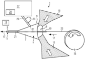
도 1은 구현예에 따른 에어로졸 발생 로드(3)를 생산하기 위한 장치(1)의 개략적인 측면도를 보여주고 있다. 장치(1)는 수렴 장치(5)를 포함하고 있다. 수렴 장치(5)는 깔때기 형상이며, 에어로졸 발생 로드(3)를 생산하기 위해 그 안에 형성 공간(9)을 정의하는 벽면(7)을 갖는다.1 shows a schematic side view of an
수렴 장치(5)는 제1 말단(9) 및 제2 말단(11)을 포함하고 있다. 도 1에 개략적으로 도시된 컨베이어 시스템(13)은, 예를 들어 당김에 의해, 수렴 장치(5)의 제1 말단(9)으로부터 수렴 장치(5)의 제2 말단(11)까지 축 방향(17)을 따라 수렴 장치(5)의 형성 공간(9)을 통해 충진 물질(15)을 운반한다.The converging
서셉터 가이드(19)는 축 방향(17)을 따라 수렴 장치(5)의 형성 공간(9) 내로 연장되어 있고 형성 공간(9) 내부에 출구 개구부(21)를 포함하고 있다. 컨베이어 시스템(13)은 축 방향(17)을 따라 수렴 장치(5)의 형성 공간(9)을 통해 서셉터(23)를 운반하도록 구성되어 있다. 서셉터(23)는 서셉터 가이드(19)에 의해 안내되고, 출구 개구부(21)를 통해 형성 공간(9) 내부의 서셉터 가이드(19)를 빠져나간다.The
서셉터(23)는 서셉터 밴드로서 공급 열(25)로부터 인출된다. 서셉터(23)는 교번 자기장에 노출됨으로써 가열되도록 구성되어 있다. 서셉터(23)는 유도 가열에 의해 가열될 수 있다. 서셉터(23)는, 예를 들어 금속 또는 탄소와 같은 전도성 물질로 만들어지거나 이를 포함할 수 있다.The
축 방향(17)에 수직인 단면에서 형성 공간(9)의 단면적은 축 방향(17)을 따라 감소한다. 충진 물질(15)이 수렴 장치(5)를 통해 운반될 때, 충진 물질(15)은 수렴 장치(5) 내측으로부터 수렴 장치(5)의 벽면(7)과 맞물려서 서셉터(23)를 포함하는 로드(3)로 형상화된다.In a cross section perpendicular to the
도시된 구현예에서, 충진 물질(15)은 수렴 장치(5)의 형성 공간(9)을 통해 2개의 물질 시트로서 운반된다. 2개의 시트는 서셉터 가이드(19)의 반경방향 외측에 있는 축 방향(17)을 따른 형성 공간(9)을 통해 운반된다. 도시된 구현예에서, 시트는 서셉터 가이드(19)의 대향 측면 상에서 수렴 장치(5)의 형성 공간(9)으로 진입한다. 형성 공간(9) 내에서, 시트는 수렴 장치(5)의 벽면(7)과 맞물리고 반경방향 외측으로부터 서셉터(23)에 대해 압축됨으로써 서셉터(23)를 포함하는 로드(3)로 형상화된다. 시트를 로드(3)로 형상화하는 단계는 시트의 접힘, 굽힘 및 압축 중 하나 이상을 포함할 수 있다. 바람직하게는, 시트는 수렴 장치(5)에 진입하기 전에 권축되어 시트의 접힘, 굽힘 및 압축을 용이하게 한다.In the embodiment shown, the filling
도 1에 도시된 바와 같이, 첨가제 저장부(27)는 첨가제 공급 라인(29)에 의해 수렴 장치(5)의 내측에 연결되어 있다. 첨가제 저장부(27)는 첨가제, 특히 에어로졸 발생 첨가제를 저장한다. 바람직하게는, 첨가제는 겔이거나 겔을 포함하고 있다. 특히, 첨가제는 요변성 겔일 수 있다. 첨가제 저장부(27)는 첨가제 공급 라인(29)을 통해 첨가제를 이송하는 것을 용이하게 하기 위해 첨가제 저장부(27) 내의 첨가제의 점도를 감소시키기 위한 점도 조정 수단(28)을 포함할 수 있다. 점도 조정 수단(28)은, 예를 들어, 하나 이상의 회전 블레이드 또는 히터를 포함할 수 있다.As shown in FIG. 1 , the
첨가제 공급 라인(29)은 수렴 장치(5)의 형성 공간(9) 내로 개방되어 있는 분배 개구부(31)를 갖는다. 서셉터(23) 및 충진 물질(15)이 수렴 장치(5)의 형성 공간(9)을 통해 운반되는 동안, 첨가제는, 펌프(33)로 첨가제 공급 라인(29)을 통해 첨가제를 펌핑함으로써, 첨가제 공급 라인(29)을 통해 형성 공간(9) 내로 공급된다. 첨가제 공급 라인(29)의 분배 개구부(31)는 서셉터 가이드(19)의 반경방향 외측에 있는 형성 공간(9) 내로 개방된다. 형성 공간(9)을 통해 운반될 때, 충진 물질(15)의 적어도 일부는 첨가제 공급 라인(29)의 분배 개구부(31)와 서셉터(23) 사이를 통과한다.The
도시된 구현예에서, 분배 개구부(31)는 수렴 장치(5)의 벽면(7)의 내부 표면과 본질적으로 동일 평면에 있다. 첨가제 공급 라인(29)은 수렴 장치(5)의 형성 공간(9) 내로 돌출되지 않는다. 첨가제 공급 라인(29)이 수렴 장치(5)의 형성 공간(9) 내로 반경방향으로 돌출되어 있는 대안적인 경우에, 첨가제 공급 라인(29)의 형성 공간(9) 내로의 돌출 길이는 바람직하게는 예를 들어 20mm 이하와 같이 작다.In the embodiment shown, the dispensing
첨가제가 분배 개구부(31)를 통해 형성 공간(9) 내로 수렴 장치(5) 내로 분배될 때, 첨가제는 반경방향 외측으로부터 충진 물질(15)에 공급된다. 충진 물질(15)는 첨가제용 담체로서 기능할 수 있다. 첨가제는 축 방향(17)을 따라 충진 물질(15)와 함께 취해질 수 있다.When the additive is dispensed into the converging
도 2는 생성 후의 로드(3)의 개략적인 단면도를 도시한다. 도시된 바와 같이, 서셉터(23)는 축 방향(17)을 따라(도 2의 도면 평면 내로) 로드(3) 내부에서 중앙에 연장되어 있다. 도 2에서 접힘 또는 굽힘 시트로서 도시된 충진 물질(15)는 서셉터(23)를 원주 방향으로 둘러싸는 슬리브(35)를 형성한다. 도시된 바와 같이, 충진 물질(15)는 첨가제가 상주할 수 있는 굽힘부 및 포켓을 형성한다.2 shows a schematic cross-sectional view of the
슬리브(35)의 반경방향 외측에 있는, 로드(3)는, 로드(3)가 수렴 장치(5)를 빠져나온 후 또는 빠져나오는 동안 슬리브(35) 주위에 래핑된 래퍼(37)를 포함하고 있다. 래퍼(37)는, 예를 들어 종이 시트로 형성될 수 있다.Radially outside of the sleeve 35, the
첨가제가 반경방향 외측으로부터 충진 물질(15) 상에 분배됨에 따라, 로드(3)는 첨가제와 서셉터(23) 사이의 직접적인 접촉 없이 제조될 수 있다.As the additive is dispensed onto the filling
도 1에 개략적으로 도시된 장치(1)는 단지 하나의 첨가제 저장부(27) 및 하나의 첨가제 공급 라인(29)을 포함하고 있다. 도 3은 하나 초과의 첨가제 저장부(27) 및 하나 초과의 첨가제 공급 라인(29)을 갖는 대안적인 구현예를 개략적으로 도시한다. 상세하게, 도 3의 구현예는 4개의 첨가제 저장부(27) 및 대응하는 4개의 첨가제 공급 라인(29)을 도시되어 있다. 추가 첨가제 공급 라인(29), 및 펌프(33)에 대응하는 3개의 추가 첨가제 저장부(27)가 있는 것을 제외하고, 도 3에 도시된 장치(1)의 기능적 원리 및 일반적인 구성이 도 1에 도시된 장치(1)의 것과 유사하다.The
도 3에서, 각각의 첨가제 공급 라인(29)은, 대응하는 첨가제 저장부(27)로부터의 첨가제가 형성 공간(9) 내로 분배되는 대응하는 분배 개구부(31)를 통해 수렴 장치(5)의 형성 공간(9) 내로 개방된다. 분배 개구부(31)는 서셉터 가이드(19)의 반경방향 외측에 있는 형성 공간(9) 내로 개방되고, 충진 물질(15)의 적어도 일부는 수렴 장치(5)를 통해 운반될 때 분배 개구부(31)와 서셉터(23) 사이를 통과한다.In FIG. 3 , each
도 3에서, 2쌍의 첨가제 공급 라인(29) 및 대응하는 첨가제 저장부(27)가 있다. 제1 쌍의 첨가제 공급 라인(29)은 도 3의 서셉터 가이드(19) 위에 도시되어 있고, 다른 쌍의 첨가제 공급 라인(29)은 서셉터 가이드(19) 아래에 도 3에 도시되어 있다. 제1 쌍의 공급 라인(29)의 분배 개구부(31) 및 제2 쌍의 공급 라인(29)의 분배 개구부(31)는 서셉터(23) 및 서셉터 가이드(19)의 대향 측면 상에 제공되어 있다. 도 3에 도시된 첨가제 공급 라인(29)의 분배 개구부(31)는 대칭 축 방향으로서 축 방향(17)에 대해 대칭으로 배열되어 있다. 동일한 쌍의 공급 라인(29)의 첨가제 공급 라인(29)의 분배 개구부(31)는 축 방향(17)을 따라 서로 뒤에 배열되어 있다.In Fig. 3, there are two pairs of
대응하는 분배 개구부(31)를 갖는 다수의 첨가제 공급 라인(29)을 가짐으로써, 상이한 위치에서 형성 공간(9) 내로 첨가제를 분배시켜 충진 물질(15) 상에 첨가제의 원하는 분포를 달성할 수 있다. 대응하는 첨가제 공급 라인(29)을 갖는 다수의 첨가제 저장부(27)를 가짐으로써, 상이한 분배 개구부(31)를 통해 상이한 종류의 첨가제를 분배할 수 있게 한다. 예를 들어, 도 3의 4개의 첨가제 저장부 모두는 상이한 종류의 첨가제를 보유할 수 있거나, 첨가제 저장부 중 2개 또는 3개만이 상이한 종류의 첨가제를 보유할 수 있다. 대안적으로, 4개의 첨가제 저장부(27) 모두가 동일한 종류의 첨가제를 보유할 수 있다.By having a plurality of
도 3에 도시된 구현예에 따르면, 제1 쌍의 첨가제 공급 라인(29)(도 3의 상부 쌍)에는, 첨가제 공급 라인(29)에 의해 공급되는 첨가제의 점도를 감소시키기 위해 첨가제 공급 라인(29)을 능동적으로 가열하도록 구성되어 있는 첨가제 공급 라인 가열 조립체(41)가 제공되어 있다. 또한, 도 3에 도시된 구현예에 따르면, 수렴 장치 가열 조립체(43)가 제공되어 형성 공간(9)의 가열 영역(45)을 능동적으로 가열한다. 가열 영역(45)은 축 방향(17)에 대하여 적어도 하나의 분배 개구부(29)의 적어도 부분적으로 하류에 있다. 형성 공간(9)에서 가열 영역(45)을 가열함으로써, 첨가제의 점도는 첨가제가 첨가제 공급 라인(29)을 떠난 후에도 낮게 유지될 수 있다. 이는 충진 물질(15) 위로의 첨가제의 분포를 용이하게 할 수 있다.According to the embodiment shown in FIG. 3 , the first pair of additive supply lines 29 (upper pair in FIG. 3 ) include an additive supply line ( 29) is provided. Also according to the embodiment shown in FIG. 3 , a converging
도 3에 도시된 구현예에서, 냉각 조립체(47)가 제공되어 가열 영역(45)의 하류에 있는 로드(3)를 능동적으로 냉각시킨다. 냉각 조립체(47)는, 첨가제의 점도를 증가시키고 본질적으로 슬리브(35) 내부의 첨가제의 분포를 고정하도록 로드(3)를 냉각시킬 수 있다.In the embodiment shown in FIG. 3 , a cooling
도 3은 또한 수렴 장치(5)의 제2 말단(11)의 하류에 있는 래핑 조립체(51)를 도시한다. 래핑 조립체(51)는 도 2에 도시된 종이 래퍼(37)와 같은 래퍼(37)로 로드(3)를 포장하도록 구성되어 있다.3 also shows the wrapping
첨가제 공급 라인 가열 조립체(41), 수렴 장치 가열 조립체(43), 및 냉각 조립체(47)는 도 3에만 도시되어 있지만, 이들 특징부 중 임의의 하나 이상이 도 1의 장치(1)에 유사하게 포함될 수 있다.Additive supply
Claims (15)
축 방향을 따라 수렴하는 형성 공간을 갖는 수렴 장치;
상기 수렴 장치의 형성 공간 내로 연장되어 있고 상기 수렴 장치의 형성 공간 내에 서셉터용 출구 개구부를 포함하는 서셉터 가이드;
바람직하게는 시트로서 형성된 충진 물질을, 상기 수렴 장치의 형성 공간을 통해 운반하여 상기 충진 물질을 상기 서셉터를 포함하는 로드로 형상화하도록 구성되어 있는 컨베이어 시스템; 및
상기 서셉터 가이드의 반경방향 외측에 있는 상기 수렴 장치의 형성 공간 내로 개방되는 분배 개구부를 갖는 적어도 하나의 첨가제 공급 라인을 포함하는, 장치.An apparatus for producing an aerosol-generating rod comprising:
a converging device having a forming space converging along an axial direction;
a susceptor guide extending into the forming space of the converging device and including an outlet opening for the susceptor in the forming space of the converging device;
a conveyor system configured to convey a filling material preferably formed as a sheet through a forming space of the converging device to shape the filling material into a rod including the susceptor; and
at least one additive supply line having a distribution opening opening into the forming space of the converging device radially outside the susceptor guide.
축 방향을 따라 수렴 장치의 형성 공간을 통해 서셉터 밴드를 운반하는 단계;
상기 축 방향을 따라 상기 수렴 장치의 형성 공간을 통해 충진 물질을 운반함으로써, 바람직하게는 시트 형태인 충진 물질을 상기 서셉터 밴드를 포함하는 로드로 형상화하는 단계; 및
상기 수렴 장치의 형성 공간 내로 개방되는 제1 분배 개구부를 통해 상기 충진 물질 상에 첨가제를 분배하는 단계를 가지고,
상기 충진 물질의 적어도 일부는 상기 수렴 장치의 형성 공간을 통해 운반되는 동안 상기 제1 분배 개구부와 상기 서셉터 밴드 사이를 통과하는, 방법.A method for producing an aerosol-generating rod comprising:
conveying the susceptor band through the forming space of the converging device along the axial direction;
shaping the filling material, preferably in the form of a sheet, into a rod including the susceptor band by conveying the filling material through the forming space of the converging device along the axial direction; and
dispensing an additive on the filling material through a first dispensing opening opening into a forming space of the converging device;
wherein at least a portion of the fill material passes between the first dispensing opening and the susceptor band while being conveyed through the forming space of the converging device.
교번 자기장에 서셉터를 노출시킴으로써 가열 가능한 서셉터;
충진 물질의 슬리브로서, 상기 서셉터를 포함하는 로드를 형성하기 위해 상기 서셉터를 둘러싸고 있는, 상기 충진 물질의 슬리브; 및
에어로졸 발생 겔과 상기 서셉터 사이의 직접적인 접촉 없이, 상기 충진 물질의 슬리브 내부에 제공된, 에어로졸 발생 겔을 포함하는, 에어로졸 발생 로드.As an aerosol generating rod,
a susceptor heatable by exposing the susceptor to an alternating magnetic field;
a sleeve of fill material surrounding the susceptor to form a rod containing the susceptor; and
An aerosol-generating rod comprising an aerosol-generating gel provided inside the sleeve of the fill material, without direct contact between the aerosol-generating gel and the susceptor.
Applications Claiming Priority (3)
| Application Number | Priority Date | Filing Date | Title |
|---|---|---|---|
| EP20201038 | 2020-10-09 | ||
| EP20201038.5 | 2020-10-09 | ||
| PCT/EP2021/077855 WO2022074190A2 (en) | 2020-10-09 | 2021-10-08 | Applying an additive from radially outside upon production of an aerosol-generating rod |
Publications (1)
| Publication Number | Publication Date |
|---|---|
| KR20230081721A true KR20230081721A (en) | 2023-06-07 |
Family
ID=72826734
Family Applications (1)
| Application Number | Title | Priority Date | Filing Date |
|---|---|---|---|
| KR1020237015486A KR20230081721A (en) | 2020-10-09 | 2021-10-08 | Application of additives from the radial outside in the production of aerosol-generating rods |
Country Status (7)
| Country | Link |
|---|---|
| US (1) | US20230354881A1 (en) |
| EP (1) | EP4225057A2 (en) |
| JP (1) | JP2023545773A (en) |
| KR (1) | KR20230081721A (en) |
| CN (1) | CN116367737A (en) |
| BR (1) | BR112023006198A2 (en) |
| WO (1) | WO2022074190A2 (en) |
Family Cites Families (6)
| Publication number | Priority date | Publication date | Assignee | Title |
|---|---|---|---|---|
| US4979521A (en) * | 1988-07-19 | 1990-12-25 | R. J. Reynolds Tobacco Company | Process for manufacturing cigarette rods |
| GB0702769D0 (en) * | 2007-02-13 | 2007-03-21 | British American Tobacco Co | A Method and apparatus for the manufacture of smoking articles |
| AR111392A1 (en) * | 2017-03-31 | 2019-07-10 | Philip Morris Products Sa | SUSCEPTING UNIT TO HEAT BY INDUCTION AN AEROSOL FORMER SUBSTRATE |
| DE102017109897A1 (en) * | 2017-05-09 | 2018-11-15 | Hauni Maschinenbau Gmbh | Infeed finger of a format device and method for operating a stranding machine |
| US11058141B2 (en) * | 2017-06-15 | 2021-07-13 | Philip Morris Products S.A. | Method and apparatus for manufacturing inductively heatable aerosol-forming rods |
| WO2020174026A1 (en) * | 2019-02-28 | 2020-09-03 | Philip Morris Products S.A. | Inductively heatable aerosol-forming rods and shaping device for usage in the manufacturing of such rods |
-
2021
- 2021-10-08 BR BR112023006198A patent/BR112023006198A2/en unknown
- 2021-10-08 CN CN202180065054.4A patent/CN116367737A/en active Pending
- 2021-10-08 KR KR1020237015486A patent/KR20230081721A/en unknown
- 2021-10-08 JP JP2023521579A patent/JP2023545773A/en active Pending
- 2021-10-08 WO PCT/EP2021/077855 patent/WO2022074190A2/en active Search and Examination
- 2021-10-08 EP EP21790155.2A patent/EP4225057A2/en active Pending
- 2021-10-08 US US18/029,405 patent/US20230354881A1/en active Pending
Also Published As
| Publication number | Publication date |
|---|---|
| JP2023545773A (en) | 2023-10-31 |
| WO2022074190A3 (en) | 2022-05-19 |
| WO2022074190A2 (en) | 2022-04-14 |
| CN116367737A (en) | 2023-06-30 |
| US20230354881A1 (en) | 2023-11-09 |
| BR112023006198A2 (en) | 2023-05-09 |
| EP4225057A2 (en) | 2023-08-16 |
Similar Documents
| Publication | Publication Date | Title |
|---|---|---|
| US20220279836A1 (en) | Method for the manufacture of susceptor sheet material comprising an aerosol-forming gel and dosing system | |
| CN113490428A (en) | Tubular element comprising porous medium for use with an aerosol-generating article | |
| CN113163863A (en) | Aerosol-generating article and method for manufacturing an aerosol-generating article | |
| CN113163866A (en) | Aerosol-generating article comprising a heat source | |
| BR112021010478A2 (en) | Aerosol generating article for use with an aerosol generating device | |
| CN113260262A (en) | Tubular element comprising a porous medium and a wrapper for use with an aerosol-generating article | |
| KR20230081721A (en) | Application of additives from the radial outside in the production of aerosol-generating rods | |
| JP2023054252A (en) | Heating type cigarette, heating type cigarette product, production method of cigarette rod in heating type cigarette and production device | |
| BR112021009143A2 (en) | tubular element for use with an aerosol generating article | |
| CN116669578A (en) | Aerosol-generating article with wrapper | |
| KR20230101830A (en) | Methods and apparatus for manufacturing components of aerosol-generating articles | |
| CN113613514B (en) | Tubular element for use with an aerosol-generating article | |
| US20230404139A1 (en) | Flanged inner hole diameter adjustment as aerosol enhancer | |
| US20230371578A1 (en) | Applying an additive upon shaping sheet material into a rod incorporating a heatable susceptor | |
| CN116685219A (en) | Aerosol-generating article comprising a wrapper | |
| KR102663246B1 (en) | Aerosol generating device | |
| KR20230005918A (en) | Aerosol-generating rod segments and aerosol-generating articles comprising such segments | |
| RU2811971C2 (en) | Aerosol-generating article, method of its manufacture and aerosol-generating device containing such product | |
| JP2023537801A (en) | aerosol generator | |
| AP232A (en) | Tobbacco sheet and method and apparatus for the production of a tobbacco sheet. | |
| WO2024003308A1 (en) | Aerosol-generating article having two aerosol-generating segments | |
| RU2021129391A (en) | ARTICLE FOR USE IN A NON-BURNING AEROSOL DELIVERY SYSTEM | |
| CN116507227A (en) | Aerosol-generating article with tubular element and ventilation | |
| WO2022129597A1 (en) | Aerosol-generating article with hollow tubular element | |
| KR20230084225A (en) | Application of additives from the inside while forming the sheet into rods |