KR20230068661A - Body for vehicle - Google Patents
Body for vehicle Download PDFInfo
- Publication number
- KR20230068661A KR20230068661A KR1020210154688A KR20210154688A KR20230068661A KR 20230068661 A KR20230068661 A KR 20230068661A KR 1020210154688 A KR1020210154688 A KR 1020210154688A KR 20210154688 A KR20210154688 A KR 20210154688A KR 20230068661 A KR20230068661 A KR 20230068661A
- Authority
- KR
- South Korea
- Prior art keywords
- vehicle
- base part
- pillar
- base
- tubular
- Prior art date
Links
Images


Classifications
-
- B—PERFORMING OPERATIONS; TRANSPORTING
- B62—LAND VEHICLES FOR TRAVELLING OTHERWISE THAN ON RAILS
- B62D—MOTOR VEHICLES; TRAILERS
- B62D25/00—Superstructure or monocoque structure sub-units; Parts or details thereof not otherwise provided for
- B62D25/02—Side panels
-
- B—PERFORMING OPERATIONS; TRANSPORTING
- B62—LAND VEHICLES FOR TRAVELLING OTHERWISE THAN ON RAILS
- B62D—MOTOR VEHICLES; TRAILERS
- B62D27/00—Connections between superstructure or understructure sub-units
- B62D27/02—Connections between superstructure or understructure sub-units rigid
-
- B—PERFORMING OPERATIONS; TRANSPORTING
- B62—LAND VEHICLES FOR TRAVELLING OTHERWISE THAN ON RAILS
- B62D—MOTOR VEHICLES; TRAILERS
- B62D25/00—Superstructure or monocoque structure sub-units; Parts or details thereof not otherwise provided for
- B62D25/04—Door pillars ; windshield pillars
-
- B—PERFORMING OPERATIONS; TRANSPORTING
- B60—VEHICLES IN GENERAL
- B60R—VEHICLES, VEHICLE FITTINGS, OR VEHICLE PARTS, NOT OTHERWISE PROVIDED FOR
- B60R13/00—Elements for body-finishing, identifying, or decorating; Arrangements or adaptations for advertising purposes
- B60R13/04—External Ornamental or guard strips; Ornamental inscriptive devices thereon
-
- B—PERFORMING OPERATIONS; TRANSPORTING
- B62—LAND VEHICLES FOR TRAVELLING OTHERWISE THAN ON RAILS
- B62D—MOTOR VEHICLES; TRAILERS
- B62D25/00—Superstructure or monocoque structure sub-units; Parts or details thereof not otherwise provided for
- B62D25/06—Fixed roofs
-
- B—PERFORMING OPERATIONS; TRANSPORTING
- B62—LAND VEHICLES FOR TRAVELLING OTHERWISE THAN ON RAILS
- B62D—MOTOR VEHICLES; TRAILERS
- B62D25/00—Superstructure or monocoque structure sub-units; Parts or details thereof not otherwise provided for
- B62D25/08—Front or rear portions
-
- B—PERFORMING OPERATIONS; TRANSPORTING
- B62—LAND VEHICLES FOR TRAVELLING OTHERWISE THAN ON RAILS
- B62D—MOTOR VEHICLES; TRAILERS
- B62D27/00—Connections between superstructure or understructure sub-units
- B62D27/02—Connections between superstructure or understructure sub-units rigid
- B62D27/023—Assembly of structural joints
-
- B—PERFORMING OPERATIONS; TRANSPORTING
- B62—LAND VEHICLES FOR TRAVELLING OTHERWISE THAN ON RAILS
- B62D—MOTOR VEHICLES; TRAILERS
- B62D29/00—Superstructures, understructures, or sub-units thereof, characterised by the material thereof
- B62D29/001—Superstructures, understructures, or sub-units thereof, characterised by the material thereof characterised by combining metal and synthetic material
- B62D29/005—Superstructures, understructures, or sub-units thereof, characterised by the material thereof characterised by combining metal and synthetic material preformed metal and synthetic material elements being joined together, e.g. by adhesives
-
- B—PERFORMING OPERATIONS; TRANSPORTING
- B62—LAND VEHICLES FOR TRAVELLING OTHERWISE THAN ON RAILS
- B62D—MOTOR VEHICLES; TRAILERS
- B62D63/00—Motor vehicles or trailers not otherwise provided for
- B62D63/02—Motor vehicles
- B62D63/025—Modular vehicles
-
- B—PERFORMING OPERATIONS; TRANSPORTING
- B60—VEHICLES IN GENERAL
- B60Y—INDEXING SCHEME RELATING TO ASPECTS CROSS-CUTTING VEHICLE TECHNOLOGY
- B60Y2304/00—Optimising design; Manufacturing; Testing
- B60Y2304/05—Reducing production costs, e.g. by redesign
-
- B—PERFORMING OPERATIONS; TRANSPORTING
- B60—VEHICLES IN GENERAL
- B60Y—INDEXING SCHEME RELATING TO ASPECTS CROSS-CUTTING VEHICLE TECHNOLOGY
- B60Y2304/00—Optimising design; Manufacturing; Testing
- B60Y2304/07—Facilitating assembling or mounting
-
- B—PERFORMING OPERATIONS; TRANSPORTING
- B60—VEHICLES IN GENERAL
- B60Y—INDEXING SCHEME RELATING TO ASPECTS CROSS-CUTTING VEHICLE TECHNOLOGY
- B60Y2306/00—Other features of vehicle sub-units
- B60Y2306/01—Reducing damages in case of crash, e.g. by improving battery protection
-
- B—PERFORMING OPERATIONS; TRANSPORTING
- B62—LAND VEHICLES FOR TRAVELLING OTHERWISE THAN ON RAILS
- B62D—MOTOR VEHICLES; TRAILERS
- B62D29/00—Superstructures, understructures, or sub-units thereof, characterised by the material thereof
- B62D29/008—Superstructures, understructures, or sub-units thereof, characterised by the material thereof predominantly of light alloys, e.g. extruded
Abstract
본 발명에 따르면 차량의 길이방향으로 연장되어 차량 외측을 향해 개방된 플랜지부가 형성된 베이스파트; 베이스파트의 플랜지부에 안착되어 결합되고, 폐단면의 파이프 형상인 튜블러파트; 및 튜블러파트의 외측을 커버링하도록 베이스파트 또는 튜블러파트에 체결되는 아우터가니쉬;를 포함하는 차량의 바디가 소개된다.According to the present invention, the base part extending in the longitudinal direction of the vehicle and having a flange portion open toward the outside of the vehicle is formed; A tubular part that is seated and coupled to the flange part of the base part and has a pipe shape of a closed cross section; and an outer garnish fastened to the base part or the tubular part so as to cover the outside of the tubular part.
Description
본 발명은 차량의 바디에 관한 것으로 차체의 전방부, 후방부 및 하부를 일체로 제조하고 어퍼바디를 제조하여 결합시킴으로써 전방부, 후방부 및 하부를 공유하는 다양한 차량에 적용하기 위한 기술이다.The present invention relates to a body of a vehicle, and is a technology for applying to various vehicles that share the front, rear, and lower parts of a vehicle by integrally manufacturing the front, rear, and lower parts of the body and manufacturing and combining the upper body.
종래 Steel BIW 어퍼바디 프레임은 루프/사이드/윈드쉴드/리드부 개구부가 개별단면을 구성하고 있고 개구부 멤버가 부분적으로 개단면을 이루고 있다. 즉, A필러 및 루프 사이드 측 멤버의 단부가 끊어지듯이 단절되고 단절된 단부가 타 멤버와 연결되는 구조였던 것이다.In the conventional Steel BIW upper body frame, the roof/side/windshield/lid part openings constitute individual cross sections, and the opening members partially form open cross sections. That is, it was a structure in which the ends of the A-pillar and the roof side members were disconnected as if they were cut off, and the disconnected ends were connected to other members.
이러한 어퍼바디 부품의 개구부 및 개단면에 의하여, 차체 강성/천장 강도 및 내구 성능의 확보가 어려웠고, 폐단면 구조를 구성하기 위하여는 조립 및 연결 등을 위한 부품 수의 증가 및 조립성 문제가 발생하였던 것이다.Due to the openings and cross-sections of these upper body parts, it was difficult to secure body rigidity/ceiling strength and durability performance, and to construct a closed cross-section structure, the number of parts for assembly and connection increased and assembly problems will be.
따라서, 종래의 단절된 멤버 연결구조에 의할 경우 충돌 또는 전복시 승객 공간을 최대한 유지할 수 있도록 하는 강도의 확보가 어려운 문제가 있었다.Therefore, in the case of the conventional disconnected member connection structure, it is difficult to secure strength to maximize the passenger space in the event of a collision or rollover.
상기의 배경기술로서 설명된 사항들은 본 발명의 배경에 대한 이해 증진을 위한 것일 뿐, 이 기술분야에서 통상의 지식을 가진 자에게 이미 알려진 종래기술에 해당함을 인정하는 것으로 받아들여져서는 안 될 것이다.The matters described as the background art above are only for improving understanding of the background of the present invention, and should not be taken as an admission that they correspond to prior art already known to those skilled in the art.
본 발명은 이러한 문제점을 해결하기 위하여 제안된 것으로, 차체의 전방부, 후방부 및 하부를 일체로 제조하고 a필러부터 루프의 측면을 별물로 제조하여 결합시킴으로써 전방부, 후방부 및 하부를 공유하는 다양한 차량에 적용하기 위함에 그 목적이 있다.The present invention has been proposed to solve this problem, and the front, rear, and lower parts of the vehicle body are integrally manufactured, and the sides of the roof from the a-pillar are separately manufactured and combined to share the front, rear, and lower parts. Its purpose is to apply to various vehicles.
본 발명에 따른 차량의 바디는 차량의 길이방향으로 연장되어 차량 외측을 향해 개방된 플랜지부가 형성된 베이스파트; 베이스파트의 플랜지부에 안착되어 결합되고, 폐단면의 파이프 형상인 튜블러파트; 및 튜블러파트의 외측을 커버링하도록 베이스파트 또는 튜블러파트에 체결되는 아우터가니쉬;를 포함한다.A body of a vehicle according to the present invention includes a base part extending in the longitudinal direction of the vehicle and having a flange portion open toward the outside of the vehicle; A tubular part that is seated and coupled to the flange part of the base part and has a pipe shape of a closed cross section; and an outer garnish fastened to the base part or the tubular part so as to cover the outside of the tubular part.
금속 재질로 제조되어 차체의 전방부, 후방부 및 전방부와 후방부를 연결하는 하부를 포함하는 베이스프레임;을 더 포함하고, 베이스파트, 튜블러파트 또는 아우터가니쉬는 전단이 전방부에 연결되며, 후단이 후방부에 연결될 수 있다.A base frame made of metal and including a front part, a rear part, and a lower part connecting the front part and the rear part of the vehicle body; and the base part, the tubular part, or the outer garnish has a front end connected to the front part, The rear end may be connected to the rear part.
베이스파트 및 튜블러파트의 내측에 결합되어 베이스파트 및 튜블러파트를 전방부와 연결시키는 이너브라켓; 및 베이스파트 및 튜블러파트의 외측에 결합되어 베이스파트 및 튜블러파트를 전방부와 연결시키는 아우터브라켓;을 더 포함할 수 있다.An inner bracket coupled to the inside of the base part and the tubular part to connect the base part and the tubular part to the front part; and an outer bracket coupled to the outside of the base part and the tubular part to connect the base part and the tubular part to the front part.
이너브라켓은 전방부 내판의 외측에 결합되고, 아우터브라켓은 전방부 외판의 외측에 결합될 수 있다.The inner bracket may be coupled to the outer side of the front inner plate, and the outer bracket may be coupled to the outer side of the front outer plate.
이너브라켓은 전방부 내판의 내측에 결합되고, 아우터브라켓은 전방부 외판의 외측에 결합될 수 있다.The inner bracket may be coupled to the inner side of the front inner plate, and the outer bracket may be coupled to the outer side of the front outer plate.
베이스프레임의 후방부에는 루프측으로 연장된 C필러가 형성되고, 하부에는 루프 측으로 연장된 B필러가 형성되며, 베이스파트 및 튜블러파트의 후단은 C필러에 연결되고, 베이스파트 및 튜블러파트의 중간측은 B필러에 연결될 수 있다.A C-pillar extending to the roof side is formed at the rear of the base frame, a B-pillar extending to the roof side is formed at the bottom, the rear ends of the base part and the tubular part are connected to the C-pillar, and the base part and the tubular part The middle side can be connected to the B-pillar.
튜블러파트와 연결되어 튜블러파트를 B필러 외판과 연결하는 B필러브라켓;을 더 포함하고, 베이스파트는 B필러 내판과 연결될 수 있다.A B-pillar racket that is connected to the tubular part and connects the tubular part to the B-pillar outer plate; and the base part may be connected to the B-pillar inner plate.
베이스파트는 B필러 내판의 외측에 연결되고, B필러브라켓은 B필러 외판의 외측에 연결될 수 있다. The base part may be connected to the outside of the B-pillar inner plate, and the B-pillar racket may be connected to the outside of the B-pillar outer plate.
베이스파트는 C필러 외판에 연결되고, 아우터가니쉬는 C필러 외판의 하단부에 연결될 수 있다. The base part may be connected to the C-pillar outer plate, and the outer garnish may be connected to the lower part of the C-pillar outer plate.
플랜지부에는 베이스파트의 상부에 연결되어 외측으로 연장된 상부플랜지 및 베이스파트의 하부에 연결되어 외측으로 연장된 하부플랜지가 포함되어 오픈 플랜지로 형성되고, 튜블러파트는 상부플랜지와 하부플랜지 사이에 안착되어 베이스파트와 결합될 수 있다.The flange part includes an upper flange connected to the upper part of the base part and extending outwardly and a lower flange connected to the lower part of the base part and extending outward to form an open flange, and the tubular part is formed between the upper flange and the lower flange. It can be seated and combined with the base part.
베이스파트, 플랜지부 및 튜블러파트는 금속 재질로 재조되어 용접으로 접합될 수 있다.The base part, the flange part, and the tubular part may be made of metal and joined by welding.
금속 재질로 제조된 베이스파트, 플랜지부 및 튜블러파트는 플라스틱 재질의 아우터가니쉬와 기계적 결합에 의해 결합될 수 있다.The base part, the flange part, and the tubular part made of metal may be coupled to the outer garnish made of plastic by mechanical coupling.
베이스파트, 튜블러파트 및 아우터가니쉬는 차량의 횡방향 양측에 한 쌍이 마련되고, 각각의 베이스파트에서 루프 측으로 연결되는 루프멤버;를 더 포함할 수 있다.The base part, the tubular part, and the outer garnish may further include a pair of roof members provided on both sides in the transverse direction of the vehicle and connected from each base part to the roof side.
베이스파트와 루프멤버를 연결시키는 루프브라켓;을 더 포함할 수 있다.It may further include a loop bracket connecting the base part and the loop member.
베이스파트는 양단부가 A필러와 루프 사이드측을 일체로 연결할 수 있다.Both ends of the base part may integrally connect the A-pillar and the roof side.
아우터가니쉬는 차량의 외관을 이루며, 플라스틱 재질로 제조될 수 있다.The outer garnish constitutes the exterior of the vehicle and may be made of a plastic material.
본 발명에 따른 차체의 전방부, 후방부 및 하부를 일체로 제조하고, A필러부터 루프의 측면을 베이스파트와 베이스파트에 폐단면 형상의 튜블러파트를 베이스파트에 형성된 오픈 플랜지에 결합시켜 전방부, 후방부 및 하부에 결합시켜 차량의 A필러 부터 루프의 측면을 단절되지 않고 연속적으로 연장된 형상으로 제조함으로써 차량의 어퍼 측 바디의 강성을 향상시킬 수 있는 효과가 있다.The front part, the rear part and the lower part of the vehicle body according to the present invention are integrally manufactured, and the side of the roof from the A-pillar is coupled to the base part and the tubular part in the shape of a closed cross-section to the base part to the open flange formed on the base part. It is effective to improve the rigidity of the upper side body of the vehicle by manufacturing the side surface of the roof from the A-pillar of the vehicle in a continuously extended shape without being disconnected by combining the upper portion, the rear portion, and the lower portion of the vehicle.
오픈 플랜지 제조시 베이스파트를 프레스 공정으로 제조하고 플랜지부를 별물로 제조하여 베이스파트에 결합시킴으로 오픈 플랜지 형상을 형성시킴에 따라 원가를 절감시킬 수 있는 효과가 있다.In manufacturing the open flange, the base part is manufactured through a press process, and the flange part is manufactured separately and coupled to the base part to form an open flange shape, thereby reducing costs.
또한, 베이스파트와 튜블러파트를 다양하게 제조할 수 있음에 따라 전방부, 후방부 및 하부를 공유하고 차량의 어퍼 측 바디가 형상이 다른 차종에 다양하게 적용될 수 있어 제조원가를 절감할 수 있는 효과가 있다.In addition, as the base part and the tubular part can be manufactured in various ways, the front part, the rear part, and the lower part are shared, and the upper side body of the vehicle can be applied to various types of vehicles with different shapes, thereby reducing manufacturing costs. there is
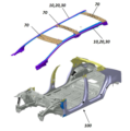
도 1은 본 발명의 일 실시예에 따른 차량의 바디의 베이스파트. 튜블러파트 및 아우터가니쉬의 분해 사시도,
도 2 내지 도 4는 본 발명의 일 실시예에 따른 차량의 바디 결합 실시예의 사시도,
도 5는 도 2의 A-A 단면도 실시예 2가지를 도시한 도면,
도 6은 도 2의 B-B 단면도,
도 7은 도 2의 C-C 단면도,
도 8은 도 3의 D-D 단면도이다.
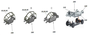
도 9는 본 발명의 일실시예에 따른 차량의 바디의 다양한 실시예를 도시한 도면이다.1 is a base part of a body of a vehicle according to an embodiment of the present invention. An exploded perspective view of tubular parts and outer garnish,
2 to 4 are perspective views of a body coupling embodiment of a vehicle according to an embodiment of the present invention;
Figure 5 is a view showing two embodiments of the AA cross-sectional view of Figure 2;
Figure 6 is a BB cross-sectional view of Figure 2;
Figure 7 is a CC cross-sectional view of Figure 2;
8 is a DD cross-sectional view of FIG. 3 .
9 is a view showing various embodiments of a body of a vehicle according to an embodiment of the present invention.
본 명세서 또는 출원에 개시되어 있는 본 발명의 실시예들에 대해서 특정한 구조적 내지 기능적 설명들은 단지 본 발명에 따른 실시예를 설명하기 위한 목적으로 예시된 것으로, 본 발명에 따른 실시예들은 다양한 형태로 실시될 수 있으며 본 명세서 또는 출원에 설명된 실시 예들에 한정되는 것으로 해석되어서는 아니 된다. Specific structural or functional descriptions of the embodiments of the present invention disclosed in this specification or application are merely illustrated for the purpose of explaining the embodiments according to the present invention, and the embodiments according to the present invention may be implemented in various forms. It may be and should not be construed as being limited to the embodiments described in this specification or application.
본 발명에 따른 실시 예는 다양한 변경을 가할 수 있고 여러 가지 형태를 가질 수 있으므로 특정실시 예들을 도면에 예시하고 본 명세서 또는 출원에 상세하게 설명하고자 한다. 그러나 이는 본 발명의 개념에 따른 실시 예를 특정한 개시 형태에 대해 한정하려는 것이 아니며, 본 발명의 사상 및 기술 범위에 포함되는 모든 변경, 균등물 내지 대체물을 포함하는 것으로 이해되어야 한다. Embodiments according to the present invention can apply various changes and can have various forms, so specific embodiments are illustrated in the drawings and described in detail in this specification or application. However, this is not intended to limit the embodiments according to the concept of the present invention to a specific disclosed form, and should be understood to include all changes, equivalents, or substitutes included in the spirit and technical scope of the present invention.
제1 및/또는 제2 등의 용어는 다양한 구성 요소들을 설명하는데 사용될 수 있지만, 상기 구성 요소들은 상기 용어들에 의해 한정되어서는 안 된다. 상기 용어들은 하나의 구성 요소를 다른 구성 요소로부터 구별하는 목적으로만, 예컨대 본 발명의 개념에 따른 권리 범위로부터 이탈되지 않은 채, 제1 구성요소는 제2 구성요소로 명명될 수 있고, 유사하게 제2 구성요소는 제1 구성요소로도 명명될 수 있다.Terms such as first and/or second may be used to describe various components, but the components should not be limited by the terms. The above terms are only for the purpose of distinguishing one component from another component, e.g., without departing from the scope of rights according to the concept of the present invention, a first component may be termed a second component, and similarly The second component may also be referred to as the first component.
어떤 구성요소가 다른 구성요소에 "연결되어" 있다거나 "접속되어" 있다고 언급된 때에는, 그 다른 구성요소에 직접적으로 연결되어 있거나 또는 접속되어 있을 수도 있지만, 중간에 다른 구성요소가 존재할 수도 있다고 이해되어야 할 것이다. 반면에, 어떤 구성요소가 다른 구성요소에 "직접 연결되어" 있다거나 "직접 접속되어" 있다고 언급된 때에는, 중간에 다른 구성요소가 존재하지 않는 것으로 이해되어야 할 것이다. 구성요소들 간의 관계를 설명하는 다른 표현들, 즉 "~사이에"와 "바로 ~사이에" 또는 "~에 이웃하는"과 "~에 직접 이웃하는" 등도 마찬가지로 해석되어야 한다. It is understood that when an element is referred to as being "connected" or "connected" to another element, it may be directly connected or connected to the other element, but other elements may exist in the middle. It should be. On the other hand, when an element is referred to as “directly connected” or “directly connected” to another element, it should be understood that no other element exists in the middle. Other expressions describing the relationship between elements, such as "between" and "directly between" or "adjacent to" and "directly adjacent to", etc., should be interpreted similarly.
본 명세서에서 사용한 용어는 단지 특정한 실시 예를 설명하기 위해 사용된 것으로, 본 발명을 한정하려는 의도가 아니다. 단수의 표현은 문맥상 명백하게 다르게 뜻하지 않는 한, 복수의 표현을 포함한다. 본 명세서에서, "포함하다" 또는 "가지다" 등의 용어는 실시된 특징, 숫자, 단계, 동작, 구성요소, 부분품 또는 이들을 조합한 것이 존재함을 지정하려는 것이지, 하나 또는 그 이상의 다른 특징들이나 숫자, 단계, 동작, 구성요소, 부분품 또는 이들을 조합한 것들의 존재 또는 부가가능성을 미리 배제하지 않는 것으로 이해되어야 한다. Terms used in this specification are only used to describe specific embodiments, and are not intended to limit the present invention. Singular expressions include plural expressions unless the context clearly dictates otherwise. In this specification, terms such as "comprise" or "have" are intended to indicate that there is an embodied feature, number, step, operation, component, part, or combination thereof, but one or more other features or numbers However, it should be understood that it does not preclude the presence or addition of steps, operations, components, parts, or combinations thereof.
다르게 정의되지 않는 한, 기술적이거나 과학적인 용어를 포함해서 여기서 사용되는 모든 용어들은 본 발명이 속하는 기술 분야에서 통상의 지식을 가진 자에 의해 일반적으로 이해되는 것과 동일한 의미이다. 일반적으로 사용되는 사전에 정의되어 있는 것과 같은 용어들은 관련 기술의 문맥상 가지는 의미와 일치하는 의미인 것으로 해석되어야 하며, 본 명세서에서 명백하게 정의하지 않는 한, 이상적이거나 과도하게 형식적인 의미로 해석되지 않는다. Unless defined otherwise, all terms used herein, including technical or scientific terms, have the same meaning as commonly understood by one of ordinary skill in the art to which the present invention belongs. Terms such as those defined in commonly used dictionaries should be interpreted as having a meaning consistent with the meaning in the context of the related art, and unless explicitly defined herein, they are not interpreted in an ideal or excessively formal meaning. .
이하, 첨부한 도면을 참조하여 본 발명의 바람직한 실시 예를 설명함으로써, 본 발명을 상세히 설명한다. 각 도면에 제시된 동일한 참조부호는 동일한 부재를 나타낸다.Hereinafter, the present invention will be described in detail by describing preferred embodiments of the present invention with reference to the accompanying drawings. Like reference numerals in each figure indicate like elements.
도 1은 본 발명의 일 실시예에 따른 차량의 바디의 베이스파트(10). 튜블러파트(20) 및 아우터가니쉬(30)의 분해 사시도, 도 2 내지 도 4는 본 발명의 일 실시예에 따른 차량의 바디 결합 실시예의 사시도, 도 5는 도 2의 A-A 단면도 실시예 2가지를 도시한 도면, 도 6은 도 2의 B-B 단면도, 도 7은 도 2의 C-C 단면도, 도 8은 도 3의 D-D 단면도이다.1 is a
도 1 내지 도 8에 도시된 바와 같이 본 발명에 따른 차량의 바디의 바람직한 실시예에 대해 알아보도록 한다.As shown in FIGS. 1 to 8 , a preferred embodiment of a body of a vehicle according to the present invention will be described.
본 발명에 따른 차량의 바디는 차량의 길이방향으로 연장되어 A필러와 루프 사이드측을 일체로 연결하는 형상이며, 차량 외측을 향해 개방된 플랜지부가 형성된 베이스파트(10); 베이스파트(10)를 따라 길이방향으로 연장된 형상이며, 베이스파트(10)의 플랜지부에 안착되어 결합되고, 폐단면의 절곡된 파이프 형상인 튜블러파트(20); 및 베이스파트(10)를 따라 길이방향으로 연장된 형상이며, 튜블러파트(20)의 외측을 커버링하도록 베이스파트(10) 또는 튜블러파트(20)에 체결되어 차량의 외관을 이루는 플라스틱 재질의 아우터가니쉬(30);를 포함한다.A body of a vehicle according to the present invention has a shape that extends in the longitudinal direction of the vehicle and integrally connects an A-pillar and a roof side side, and includes a
베이스파트(10)는 차량의 외측 방향으로 오픈 플랜지 형상으로 형성되며, 오픈 플랜지에 튜블러파트(20)가 안착되며 베이스파트(10)와 결합될 수 있다.The
베이스파트(10)는 프레스 공정에 의해 금속 재질로 제조될 수 있으며, 튜블러파트(20)는 알루미늄 압출성형과 같은 금속재질의 파이프 형상으로 제조되고 후처리 가공에 의해 베이스파트(10)의 오픈 플랜지에 안착되도록 성형될 수 있다.The
금속 철판을 프레스 성형하여 제조된 베이스파트(10)에 금속 파이프 형태의 튜블러파트(20)가 결합됨으로써 베이스파트(10)의 부족한 강성을 보강할 수 있으며, 베이스파트(10)를 프레스 성형하여 제조하고 압출 성형 및 후처리 가공을 통해 튜블러파트(20)를 제조함으로써 원가 절감의 효과가 있다.By combining the
또한, 차량의 A필러 및 루프의 사이부까지 연장된 베이스파트(10) 및 튜블러파트(20)는 각각 쉽게 형상을 변경시킬 수 있음에 따라 하부 프레임 또는 플랫폼을 공유하는 다양한 차종에 변경하여 적용시킬 수 있는 편리성을 향상시킬 수 있는 효과가 있다.In addition, the
또한, 베이스파트(10)에 튜블러파트(20)가 결합된 상태에서 외판인 아우터가니쉬(30)가 베이스파트(10) 또는 튜블러파트(20)에 결합됨에 따라 차량의 외관을 형성하며 베이스파트(10) 및 튜블러파트(20)의 강성을 향상시킬 수 있는 효과가 있다.In addition, in the state in which the
아우터가니쉬(30)는 스틸 재질로 프레스 성형되어 제조되거나 또는 플라스틱과 같은 재질로 제조될 수 있으며 차량의 제조 원가에 따라 결정될 수 있다.The
금속 재질로 제조되어 차체의 전방부(110), 후방부(120) 및 전방부(110)와 후방부(120)를 연결하는 하부를 포함하는 베이스프레임(100);을 더 포함하고, 베이스파트(10), 튜블러파트(20) 또는 아우터가니쉬(30)는 전단이 전방부(110)에 연결되며, 후단이 후방부(120)에 연결될 수 있다.A
도 2 내지 도 4에 도시된 바와 같이 차체의 상부에 결합되는 하부는 차량의 하부, 전방부(110) 및 후방부(120)까지 일체로 제조된 베이스프레임(100)을 형성될 수 있으며, 베이스프레임(100)으 모노코크 바디 형태로 일체로 제조되거나, 프레임 바디와 같이 하부가 먼저 제조되고, 전방부(110)와 후방부(120)가 추가로 결합될 수 있으며, 베이스프레임(100)의 상부에 튜블러파트(20)가 삽입된 베이스파트(10) 및 아우터가니쉬(30)가 다양한 형상으로 결합될 수 있다.As shown in FIGS. 2 to 4 , the lower part coupled to the upper part of the vehicle body may form a
이를 통해 하부를 공유하며 상부가 다른 다양한 차량을 제조시 원가를 절감할 수 있는 효과가 있다.Through this, there is an effect of reducing costs when manufacturing various vehicles having different upper parts while sharing a lower part.
베이스파트(10) 및 튜블러파트(20)의 내측에 결합되어 베이스파트(10) 및 튜블러파트(20)를 전방부(110)와 연결시키는 이너브라켓(41); 및 베이스파트(10) 및 튜블러파트(20)의 외측에 결합되어 베이스파트(10) 및 튜블러파트(20)를 전방부(110)와 연결시키는 아우터브라켓(42);을 더 포함할 수 있다.An
도 1에 도시된 바와 같이 베이스파트(10)의 전단은 베이스파트(10)의 전방부(110)와 결합될 수 있으며, 이때 베이스파트(10)의 전단과 전방부(110)의 결합 강성 및 결합편의성을 향상시키기 위해 베이스파트(10)의 전단 내측에 결합되는 이너브라켓(41) 및 베이스파트(10)의 전단 외측에 결합되는 아우터 브라켓이 마련될 수 있다.As shown in FIG. 1, the front end of the
이로 인해 전방부(110)의 형상이 변형시 이너브라켓(41) 및 아우터브라켓(42)의 형상을 조금씩 변형시켜 베이스파트(10)를 전방부(110)에 결합시킬 수 있으며, 베이스파트(10) 결합방향에 따라 이너브라켓(41) 및 아우터브라켓(42)의 형상을 변형시킬 수 있다.As a result, when the shape of the
이를 통해 다양한 차종에 결합시 적용되어 원가를 절감시킬 수 있는 효과가 있으며, 결합작업의 편리성을 향상시킬 수 있는 효과가 있다.Through this, there is an effect of reducing cost by being applied to various types of vehicles and improving the convenience of coupling work.
도 9는 본 발명의 일실시예에 따른 차량의 바디의 다양한 실시예를 도시한 도면이다.9 is a view showing various embodiments of a body of a vehicle according to an embodiment of the present invention.
도 9에서 도시된 바와 같이 베이스프레임(100)은 차량의 하부측을 구성하며, 본발명의 베이스파트(10) 및 튜블러파트(20)는 베이스프레임(100)의 필러부 및 루프부의 측면을 형성할 수 있다.As shown in FIG. 9, the
도 9의 A, B, C는 베이스파트(10) 및 튜블러파트(20)가 다양한 형상으로 형성되어 차량의 베이스프레임에 결합되어 동일한 베이스프레임(100)에도 고객의 요구 사항에 따라 다양한 차종으로 제조될 수 있다.In A, B, and C of FIG. 9, the
본 발명에 따른 차량의 바디는 PBV (Purposed Build Vehicle) 차량에 적용될 수 있으며, PBV (Purposed Build Vehicle) 차량에서는 다품종 소량생산의 시장에 맞는 차량을 개발할 필요가 있다.The body of the vehicle according to the present invention can be applied to a PBV (Purposed Build Vehicle) vehicle, and in the PBV (Purposed Build Vehicle) vehicle, it is necessary to develop a vehicle suitable for the small-lot production market.
PBV차량은 고객의 요구에 따라 유연성, 디자인 자유도, 부품수 축소, 스마트 팩토리에서의 조립, 경량화, 원가절감, 공간활용도 및 성능 등이 고려되며, 이러한 고려 요소를 충족시키기 위해서는 본 발명에서 개시된 베이스프레임(100)에 튜블러파트(20)로 뼈대를 형성하고 외부에 프레스 형성으로 제조된 베이스파트(10)가 결합되어 다양한 형상의 차종을 생한하는 방식 종래의 모토코크 바디 방식 보다 상기의 고려 사항이 유리할 수 있다.PBV vehicles consider flexibility, freedom of design, reduction in the number of parts, assembly in a smart factory, light weight, cost reduction, space utilization and performance according to customer needs. In order to meet these consideration factors, the base disclosed in the present invention A method of forming a skeleton with a
본 발명의 베이스프레임(100)은 전방부와 후방부에 베이스파트(10)가 결합될 수 있으며, 전방부와 후방부는 다양한 형상으로 변형될 수 있다.In the
본 발명의 일 실시예에서는 후방부에서 연장된 c필러가 형성되어 C필러는 베이스파트에 연결되는 형상으로 도시되었으며, 또한 C필러는 다양한 형상으로 형성될 수 있다.In one embodiment of the present invention, a C-pillar extending from the rear portion is formed and the C-pillar is shown as a shape connected to the base part, and the C-pillar may be formed in various shapes.
PBV는 전기차 플랫폼에 적용될 수 있으며, 하부에 구동계통의 장치인 배터리, 모터 휠 및 서스팬션이 마련되고, 배이스프레임(100)은 구동계통 장치의 상부에 결합되어 차체를 구성할 수 있다.The PBV can be applied to an electric vehicle platform, and a battery, a motor wheel, and a suspension, which are devices of the drive system, are provided at the bottom, and the
이너브라켓(41)은 전방부 내판(110a)의 외측에 결합되고, 아우터브라켓(42)은 전방부 외판(110b)의 외측에 결합될 수 있다. The
도 2에 도시된 바와 같이 베이스파트(10)를 차량의 좌우방향으로 베이스프레임(100)에 결합되기 위해 이너브라켓(41)은 베이스프레임(100)의 전방부 내판(110a)의 외측에 결합될 수 있다. 이를 통해 이너브라켓(41)이 먼저 전방부 내판(110a)의 외측에 결합되고, 아우터브라켓(42)이 전방부 외판(110b)의 외측에 결합될 수 있다.As shown in FIG. 2, in order to couple the
도 5 A에서 도시된 바와 같이 전방부 내판(110a)의 길이는 외판의 길이보다 길게 설정될 수 있으며 이로 인해 이너브라켓(41)과 아우터브라켓(42)은 베이스패널에 결합된 상태로 베이스프레임(100)의 측방에서 베이스프레임(100)으로 결합될 수 있다. As shown in FIG. 5A, the length of the front
이를 통해 생산 라인에서 베이스프레임(100)에 측방으로 베이스파트(10)를 편리하게 결합시킬 수 있는 효과가 있다.Through this, there is an effect that the
이너브라켓(41)은 전방부 내판(110a)의 내측에 결합되고, 아우터브라켓(42)은 전방부 외판(110b)의 외측에 결합될 수 있다.The
도 3에 도시된 바와 같이 베이스파트(10)를 차량의 상하 방향으로 베이스프레임(100)에 결합되기 위해 이너브라켓(41)은 베이스프레임(100)의 전방부 내판(110a)의 내측에 결합될 수 있다. 이를 통해 이너브라켓(41)이 먼저 전방부 내판(110a)의 내측에 결합되고, 아우터브라켓(42)이 전방부(110) 외판의 외측에 결합될 수 있다.As shown in FIG. 3, in order to couple the
도 5 A에서 도시된 바와 같이 전방부 내판(110a)의 길이는 외판(110b)의 길이보다 길게 설정될 수 있으며 이로 인해 이너브라켓(41)과 아우터브라켓(42)은 베이스패널에 결합된 상태로 베이스프레임(100)의 측방에서 베이스프레임(100)으로 결합될 수 있다. As shown in Figure 5 A, the length of the front inner plate (110a) can be set longer than the length of the outer plate (110b), so that the
이를 통해 생산 라인에서 베이스프레임(100)에 측방으로 베이스파트(10)를 편리하게 결합시킬 수 있는 효과가 있다.Through this, there is an effect that the
베이스프레임(100)의 후방부(120)에는 루프 측으로 연장된 C필러(121)가 형성되고, 하부에는 루프 측으로 연장된 B필러(131)가 형성되며, 베이스파트(10) 및 튜블러파트(20)의 후단은 C필러(121)에 연결되고, 베이스파트(10) 및 튜블러파트(20)의 중간측은 B필러(131)에 연결될 수 있다.A C-
도 7에 도시된 바와 같이 베이스파트(10)의 후단은 베이스프레임(100)의 후방부(120)에서 전방으로 연장된 C필러(121)와 연결될 수 있으며, C필러(121)와 연결되기 위해 마련된 C필러브라켓(60)이 베이스프레임(100)과 연결되고, C필러브라켓(60)은 C필러(121)의 외판과 연결되어 베이스파트(10)를 연결시킬 수 있다.As shown in FIG. 7, the rear end of the
차량의 종류마다 C필러(121)의 형상이 변형되거나, 베이스파트(10)의 형상이 변형될 수 있으며, 이때 C필러브라켓(60)의 형상이 변경되어 C필러(121)와 베이스파트(10)를 연결시켜 제조공정의 편리성을 향상시킬 수 있는 효과가 있다. The shape of the C-
튜블러파트(20)와 연결되어 튜블러파트(20)를 B필러 외판(131b)과 연결하는 B필러브라켓(50);을 더 포함하고, 베이스파트(10)는 B필러 내판(131a)과 연결될 수 있다.It further includes; a B-
도 1 및 도 6에 도시된 바와 같이 베이스파트(10)의 중간측은 B필러(131)와 연결될 수 있다. As shown in FIGS. 1 and 6 , the middle side of the
이때 차량의 형상에 따라 다양한 형태로 베이스파트(10) 및 튜블러파트(20)가 형성될 수 있으며, 이러한 베이스파트(10) 및 튜블러파트(20)를 B필러(131)와 연결시키기 위해 튜블러파트(20)와 결합되는 B필러브라켓(50)이 마련될 수 있다.At this time, the
이를 통해 B필러(131)의 형상이 다양하게 형성되거나 또는 베이스파트(10) 및 튜블러파트(20)의 형상이 다양하게 형성되더라도, 베이스파트(10) 및 튜블러파트(20)을 B필러브라켓(50)에 결합시킨 이후 B필러(131)에 쉽게 결합시킬 수 있는 효과가 있다.Through this, even if the shape of the B-
베이스파트(10)는 B필러 내판(131a)의 외측에 연결되고, B필러브라켓(50)은 B필러 외판(131b)의 외측에 연결될 수 있다.The
도 6에 도시된 바와 같이 베이스파트(10) 및 튜블러파트(20)를 상방에서 하방으로 결합시키거나 또는 측방으로 결합시키는 경우에 베이스파트(10)는 B필러의 내판(131a) 외측에 결합될 수 있으며, 튜블러파트(20)와 결합된 B필러브라켓(50)은 B필러 외판(131b)의 외측에 결합될 수 있다.As shown in FIG. 6, when the
B필러(131)의 단부는 차량의 내측으로 꺾여 있으며 B필러의 내판(131a)이 외판보다 더 길게 형성되어 베이스파트(10) 및 튜블러파트(20)가 상하 방향으로 결합 또는 좌우 방향으로 결합이 가능하도록 설계될 수 있다.The end of the B-
이를 통해 생산 라인에서 다양한 방식으로 조립될 수 있어 조립 편리성을 향상시킬 수 있는 효과가 있다. Through this, it can be assembled in various ways on the production line, thereby improving assembly convenience.
베이스파트(10)는 C필러(121) 외판에 연결되고, 아우터가니쉬(30)는 C필러(121) 외판의 하단부에 연결될 수 있다. The
도 7에 도시된 바와 같이 베이스파트(10)는 C필러(121)와의 결합부분에서 상하방향 양단부가 C필러(121)의 외판에 각각 결합될 수 있으며, 아우터가니쉬(30)가 베이스파트(10)의 외측과 C필러(121)의 하단부에 결합되어 베이스파트(10) 및 튜블러파트(20)를 커버링하며 외관을 형성할 수 있다.As shown in FIG. 7 , both ends of the
베이스파트(10) 및 튜블러파트(20)는 전방부(110), B필러(131) 및 C필러(121)와 결합시 각각 금속 용접, 볼팅 또는 리벳과 같은 기계적 결합에 의해 결합되어 결합 강성을 향상시킬 수 있는 효과가 있다.When the
플랜지부에는 베이스파트(10)의 상부에 연결되어 외측으로 연장된 상부플랜지(11) 및 베이스파트(10)의 하부에 연결되어 외측으로 연장된 하부플랜지(12)가 포함되어 오픈 플랜지로 형성되고, 튜블러파트(20)는 상부플랜지(11)와 하부플랜지(12) 사이에 안착되어 베이스파트(10)와 결합될 수 있다.The flange part includes an
도 1 및 도 8에서 도시된 바와 같이 베이스파트(10)에는 튜블러파트(20)를 안착시키기 위해 플랜지부가 마련될 수 있으며, 프레스 공정에 의해 제조된 베이스파트(10)에 오픈 플랜지 형상인 플랜지부를 형성하여 제조하기엔 제조원가 상승 및 제조공정이 복잡해지는 문제가 발생한다.As shown in FIGS. 1 and 8, the
이를 해결하기 위해 베이스파트(10)의 상부에 결합되는 상부플랜지(11) 및 하부에 결합되는 하부플랜지(12)가 마련되어 오픈 플랜지 형상을 형성할 수 있으며, 상부플랜지(11)와 하부플랜지(12)로 형성된 오픈 플랜지 형상에 튜블러파트(20)가 안착되어 베이스파트(10)와 튜블러파트(20)가 쉽게 결합될 수 있는 효과가 있다.To solve this problem, an
베이스파트(10), 플랜지부 및 튜블러파트(20)는 금속 재질로 제조되어 용접으로 접합될 수 있다.The
도 8에 도시된 바와 같이 베이스파트(10), 플랜지부 및 튜블러파트(20)는 모두 금속재질로 제조되어 플라스틱과 같은 합성수지 재질보다 강성이 우수하며, 베이스파트(10) 및 플랜지부는 각각 프레스 성형으로 제조되어 용접을 통해 결합되고, 상부플랜지(11)와 하부플랜지(12)로 형성된 오픈 플랜지에 튜블러파트(20)가 안착되며 베이스파트(10), 상부플랜지(11) 및 하부플랜지(12)에 튜블러파트(20)가 용접되어 결합될 수 있다.As shown in FIG. 8, the
이를 통해 튜블러파트(20)와 베이스파트(10)가 강인하게 결합될 수 있는 효과가 있다.Through this, there is an effect that the
금속 재질로 제조된 베이스파트(10), 플랜지부 및 튜블러파트(20)는 플라스틱 재질의 아우터가니쉬(30)와 기계적 결합에 의해 결합될 수 있다.The
아우터가니쉬(30)는 플라스틱 재질로 형성되어 차량의 외관을 형성할 수 있으며 플라스틱으로 제조됨에 따라 다양한 형상으로 제조될 수 있다 차량의 외관미를 향상시키는 데에 효과가 있다.The
또한, 아우터가니쉬(30)는 플라스틱이며, 베이스프레임(100)은 금속재질로 형성되어 이종 재질 간의 결합시 볼팅 또는 리벳과 같은 기계적 결합에 의해 단단하게 결합될 수 있는 효과가 있다.In addition, since the
베이스파트(10), 튜블러파트(20) 및 아우터가니쉬(30)는 차량의 횡방향 양측에 한 쌍이 마련되고, 각각의 베이스파트(10)에서 루프 측으로 연결되는 루프멤버(80);를 더 포함할 수 있다.The
베이스파트(10)는 차량의 양 사이드 측에 결합되도록 한 쌍이 마련될 수 있으며, 베이스파트(10)의 상부로 한 쌍의 베이스파트(10)를 연결하는 루프멤버(80)가 마련되어 베이스파트(10)의 상부를 지지하며, 차체의 강성을 향상시킬 수 있는 효과가 있다.A pair of
루프멤버(80) 상측으로 루프패널(미도시) 또는 썬루프(미도시)가 장착될 수 있으며, 루프멤버(80)는 루프패널(미도시) 또는 썬루프(미도시)를 지지할 수 있다. A roof panel (not shown) or a sunroof (not shown) may be mounted above the
베이스파트(10)와 루프멤버(80)를 연결시키는 루프브라켓(70);을 더 포함할 수 있다.A
도 1에서 도시된 바와 같이 바와 같이 한 쌍의 베이스파트(10)를 서로 연결시키기 위해 루프멤버(80)가 마련될 수 있으며, 루프멤버(80)와 베이스파트(10)를 서로 연결시키기 위해 루프브라켓(70)이 마련될 수 있다.As shown in FIG. 1, a
루프브라켓(70)은 베이스파트(10) 또는 루프멤버(80)의 형상에 따라 다양한 형태로 형성될 수 있으며, 이로 인해 차량의 너비가 다른 차종에도 적용시켜 다양한 차종을 생산할 수 있는 효율성을 향상시킬 수 있는 효과가 있다.The
발명의 특정한 실시예에 관련하여 도시하고 설명하였으나, 이하의 특허청구범위에 의해 제공되는 본 발명의 기술적 사상을 벗어나지 않는 한도 내에서, 본 발명이 다양하게 개량 및 변화될 수 있다는 것은 당 업계에서 통상의 지식을 가진 자에게 있어서 자명할 것이다.Although shown and described in relation to specific embodiments of the invention, it is common in the art that the present invention can be variously improved and changed without departing from the technical spirit of the present invention provided by the claims below. It will be self-evident to those who have knowledge of
10 : 베이스파트
11 : 상부플랜지
12 : 하부플랜지
20 : 튜블러파트
30 : 아우터가니쉬
41 : 이너브라켓
42 : 아우터브라켓
50 : B필러브라켓
60 : C필러브라켓
70 : 루프브라켓
80 : 루프멤버
100 : 베이스프레임
110 : 전방부
120 : 후방부
121 : C필러
130 : 하부
131 : B필러10: Base part
11: upper flange
12: lower flange
20: Tubular part
30: Outer garnish
41: inner bracket
42: outer bracket
50 : B pillar racket
60 : C pillar racket
70: roof bracket
80: loop member
100: base frame
110: front part
120: rear part
121: C pillar
130: lower
131: B pillar
Claims (16)
베이스파트의 플랜지부에 안착되어 결합되고, 폐단면의 파이프 형상인 튜블러파트; 및
튜블러파트의 외측을 커버링하도록 베이스파트 또는 튜블러파트에 체결되는 아우터가니쉬;를 포함하는 차량의 바디.A base part extending in the longitudinal direction of the vehicle and having a flange portion open toward the outside of the vehicle;
A tubular part that is seated and coupled to the flange part of the base part and has a pipe shape of a closed cross section; and
A body of a vehicle including a base part or an outer garnish fastened to the tubular part to cover the outside of the tubular part.
금속 재질로 제조되어 차체의 전방부, 후방부 및 전방부와 후방부를 연결하는 하부를 포함하는 베이스프레임;을 더 포함하고,
베이스파트, 튜블러파트 또는 아우터가니쉬는 전단이 전방부에 연결되며, 후단이 후방부에 연결된 것을 특징으로 하는 차량의 바디.The method of claim 1,
A base frame made of metal and including a front part, a rear part, and a lower part connecting the front part and the rear part of the vehicle body; further comprising,
The base part, the tubular part, or the outer garnish is a body of a vehicle, characterized in that the front end is connected to the front part and the rear end is connected to the rear part.
베이스파트 및 튜블러파트의 내측에 결합되어 베이스파트 및 튜블러파트를 전방부와 연결시키는 이너브라켓; 및 베이스파트 및 튜블러파트의 외측에 결합되어 베이스파트 및 튜블러파트를 전방부와 연결시키는 아우터브라켓;이 더 포함되는 것을 특징으로 하는 차량의 바디.The method of claim 2,
An inner bracket coupled to the inside of the base part and the tubular part to connect the base part and the tubular part to the front part; and an outer bracket coupled to the outside of the base part and the tubular part to connect the base part and the tubular part to the front part.
이너브라켓은 전방부 내판의 외측에 결합되고, 아우터브라켓은 전방부 외판의 외측에 결합되는 것을 특징으로 하는 차량의 바디.The method of claim 3,
The inner bracket is coupled to the outer side of the front inner plate, and the outer bracket is the body of the vehicle, characterized in that coupled to the outer side of the front outer plate.
이너브라켓은 전방부 내판의 내측에 결합되고, 아우터브라켓은 전방부 외판의 외측에 결합되는 것을 특징으로 하는 차량의 바디.The method of claim 3,
The inner bracket is coupled to the inner side of the front inner plate, and the outer bracket is the body of the vehicle, characterized in that coupled to the outer side of the front outer plate.
베이스프레임의 후방부에는 루프측으로 연장된 C필러가 형성되고, 하부에는 루프 측으로 연장된 B필러가 형성되며,
베이스파트 및 튜블러파트의 후단은 C필러에 연결되고, 베이스파트 및 튜블러파트의 중간측은 B필러에 연결된 것을 특징으로 하는 차량의 바디.The method of claim 2,
A C-pillar extending to the roof side is formed at the rear of the base frame, and a B-pillar extending to the roof side is formed at the bottom,
The body of a vehicle, characterized in that the rear end of the base part and the tubular part are connected to the C-pillar, and the middle side of the base part and the tubular part is connected to the B-pillar.
튜블러파트와 연결되어 튜블러파트를 B필러 외판과 연결하는 B필러브라켓;을 더 포함하고,
베이스파트는 B필러 내판과 연결되는 것을 특징으로 하는 차량의 바디.The method of claim 6,
A B-pillar racket connected to the tubular part and connecting the tubular part to the B-pillar outer plate; further comprising,
The body of the vehicle, characterized in that the base part is connected to the B-pillar inner plate.
베이스파트는 B필러 내판의 외측에 연결되고, B필러브라켓은 B필러 외판의 외측에 연결된 것을 특징으로 하는 차량의 바디.The method of claim 7,
The body of the vehicle, characterized in that the base part is connected to the outside of the B-pillar inner plate, and the B-pillar racket is connected to the outside of the B-pillar outer plate.
베이스파트는 C필러 외판에 연결되고, 아우터가니쉬는 C필러 외판의 하단부에 연결된 것을 특징으로 하는 차량의 바디.The method of claim 6,
The body of the vehicle, characterized in that the base part is connected to the C-pillar outer plate, and the outer garnish is connected to the lower part of the C-pillar outer plate.
플랜지부에는 베이스파트의 상부에 연결되어 외측으로 연장된 상부플랜지 및 베이스파트의 하부에 연결되어 외측으로 연장된 하부플랜지가 포함되어 오픈 플랜지로 형성되고, 튜블러파트는 상부플랜지와 하부플랜지 사이에 안착되어 베이스파트와 결합되는 것을 특징으로 하는 차량의 바디.The method of claim 1,
The flange part includes an upper flange connected to the upper part of the base part and extending outwardly and a lower flange connected to the lower part of the base part and extending outward to form an open flange, and the tubular part is formed between the upper flange and the lower flange. The body of a vehicle, characterized in that it is seated and combined with the base part.
베이스파트, 플랜지부 및 튜블러파트는 금속 재질로 재조되어 용접으로 접합된 것을 특징으로 하는 차량의 바디.The method of claim 1,
A body of a vehicle, characterized in that the base part, the flange part and the tubular part are made of metal and joined by welding.
금속 재질로 제조된 베이스파트, 플랜지부 및 튜블러파트는 플라스틱 재질의 아우터가니쉬와 기계적 결합에 의해 결합된 것을 특징으로 하는 차량의 바디.The method of claim 11,
The body of a vehicle, characterized in that the base part, the flange part, and the tubular part made of a metal material are coupled to an outer garnish made of plastic by mechanical coupling.
베이스파트, 튜블러파트 및 아우터가니쉬는 차량의 횡방향 양측에 한 쌍이 마련되고, 각각의 베이스파트에서 루프 측으로 연결되는 루프멤버;를 더 포함하는 것을 특징으로 하는 차량의 바디.The method of claim 1,
The body of a vehicle, characterized in that it further comprises; a pair of base parts, tubular parts and outer garnish provided on both sides of the vehicle in the transverse direction, and loop members connected from each base part to the roof side.
베이스파트와 루프멤버를 연결시키는 루프브라켓;을 더 포함하는 것을 특징으로 하는 차량의 바디.The method of claim 13,
The vehicle body further comprising a; roof bracket connecting the base part and the roof member.
베이스파트는 양단부가 A필러와 루프 사이드측을 일체로 연결하는 것을 특징으로 하는 차량의 바디.The method of claim 1,
The base part is a body of a vehicle, characterized in that both ends integrally connect the A-pillar and the roof side.
아우터가니쉬는 차량의 외관을 이루며, 플라스틱 재질로 제조된 것을 특징으로 하는 차량의 바디.The method of claim 1,
The outer garnish forms the exterior of the vehicle and is a vehicle body, characterized in that it is made of a plastic material.
Priority Applications (4)
| Application Number | Priority Date | Filing Date | Title |
|---|---|---|---|
| KR1020210154688A KR20230068661A (en) | 2021-11-11 | 2021-11-11 | Body for vehicle |
| US17/946,285 US20230147372A1 (en) | 2021-11-11 | 2022-09-16 | Body for vehicle |
| DE102022210788.8A DE102022210788A1 (en) | 2021-11-11 | 2022-10-13 | BODY FOR VEHICLE |
| CN202211292609.1A CN116101379A (en) | 2021-11-11 | 2022-10-20 | Vehicle body |
Applications Claiming Priority (1)
| Application Number | Priority Date | Filing Date | Title |
|---|---|---|---|
| KR1020210154688A KR20230068661A (en) | 2021-11-11 | 2021-11-11 | Body for vehicle |
Publications (1)
| Publication Number | Publication Date |
|---|---|
| KR20230068661A true KR20230068661A (en) | 2023-05-18 |
Family
ID=86053220
Family Applications (1)
| Application Number | Title | Priority Date | Filing Date |
|---|---|---|---|
| KR1020210154688A KR20230068661A (en) | 2021-11-11 | 2021-11-11 | Body for vehicle |
Country Status (4)
| Country | Link |
|---|---|
| US (1) | US20230147372A1 (en) |
| KR (1) | KR20230068661A (en) |
| CN (1) | CN116101379A (en) |
| DE (1) | DE102022210788A1 (en) |
Citations (1)
| Publication number | Priority date | Publication date | Assignee | Title |
|---|---|---|---|---|
| KR20150104269A (en) | 2014-03-04 | 2015-09-15 | 현대자동차주식회사 | Upper-body frame system for vehicle |
-
2021
- 2021-11-11 KR KR1020210154688A patent/KR20230068661A/en unknown
-
2022
- 2022-09-16 US US17/946,285 patent/US20230147372A1/en active Pending
- 2022-10-13 DE DE102022210788.8A patent/DE102022210788A1/en active Pending
- 2022-10-20 CN CN202211292609.1A patent/CN116101379A/en active Pending
Patent Citations (1)
| Publication number | Priority date | Publication date | Assignee | Title |
|---|---|---|---|---|
| KR20150104269A (en) | 2014-03-04 | 2015-09-15 | 현대자동차주식회사 | Upper-body frame system for vehicle |
Also Published As
| Publication number | Publication date |
|---|---|
| CN116101379A (en) | 2023-05-12 |
| DE102022210788A1 (en) | 2023-05-11 |
| US20230147372A1 (en) | 2023-05-11 |
Similar Documents
| Publication | Publication Date | Title |
|---|---|---|
| EP1149757B1 (en) | Car body assembling method and body structure of a vehicle | |
| US6540286B2 (en) | Body structure | |
| JP5927187B2 (en) | Automobile pillar reinforcement | |
| US8690218B2 (en) | Vehicle body structure with body reinforcement behind the second row of seats | |
| CN100390007C (en) | Rear body structure of vehicle | |
| EP2471697A1 (en) | Upper vehicle body structure of automobile | |
| JP5545124B2 (en) | Vehicle roof structure | |
| EP2664521B1 (en) | Panel structure for vehicle | |
| US11472490B2 (en) | Body for vehicle | |
| JP5387323B2 (en) | Vehicle body structure | |
| CN111017034B (en) | Vehicle frame structure | |
| US7032958B2 (en) | Body and frame assembly for a vehicle and method of assembling a vehicle | |
| KR20230068661A (en) | Body for vehicle | |
| DE60123731T2 (en) | Body side part for a motor vehicle | |
| KR102474386B1 (en) | Joint structure of quarter part for vehicle | |
| CN210592144U (en) | Bearing type vehicle body structure and prowl car | |
| US11161552B2 (en) | Side-outer reinforcement panel of vehicle | |
| KR20230067148A (en) | Body for vehicle | |
| CN220785921U (en) | Automobile body rear side wall structure and vehicle | |
| CN211731579U (en) | D-pillar structure for vehicle | |
| CN219295535U (en) | Rear wheel cover assembly | |
| CN216709442U (en) | Sectional type D post planking assembly and car | |
| KR20230097847A (en) | Outter panel and manufacturing method thereof | |
| KR20230099252A (en) | Side body struture for vehicle | |
| JP2617060B2 (en) | Car upper body structure |