KR20230049088A - Secondary battery manufacturing method and secondary battery manufacturing device - Google Patents
Secondary battery manufacturing method and secondary battery manufacturing device Download PDFInfo
- Publication number
- KR20230049088A KR20230049088A KR1020237003978A KR20237003978A KR20230049088A KR 20230049088 A KR20230049088 A KR 20230049088A KR 1020237003978 A KR1020237003978 A KR 1020237003978A KR 20237003978 A KR20237003978 A KR 20237003978A KR 20230049088 A KR20230049088 A KR 20230049088A
- Authority
- KR
- South Korea
- Prior art keywords
- secondary battery
- electrode
- electrolyte
- manufacturing
- separator
- Prior art date
Links
- 238000004519 manufacturing process Methods 0.000 title claims abstract description 154
- 239000003792 electrolyte Substances 0.000 claims abstract description 230
- 238000007789 sealing Methods 0.000 claims abstract description 72
- 229920005989 resin Polymers 0.000 claims description 158
- 239000011347 resin Substances 0.000 claims description 158
- 238000000034 method Methods 0.000 claims description 84
- 239000000463 material Substances 0.000 claims description 76
- OKTJSMMVPCPJKN-UHFFFAOYSA-N Carbon Chemical compound [C] OKTJSMMVPCPJKN-UHFFFAOYSA-N 0.000 claims description 66
- 230000007246 mechanism Effects 0.000 claims description 62
- 238000012545 processing Methods 0.000 claims description 59
- 229910021389 graphene Inorganic materials 0.000 claims description 57
- 239000011149 active material Substances 0.000 claims description 53
- 239000011737 fluorine Substances 0.000 claims description 29
- 229910052731 fluorine Inorganic materials 0.000 claims description 29
- 230000001678 irradiating effect Effects 0.000 claims description 21
- 239000002608 ionic liquid Substances 0.000 claims description 20
- 239000011261 inert gas Substances 0.000 claims description 14
- 238000007906 compression Methods 0.000 claims description 13
- 230000006835 compression Effects 0.000 claims description 13
- 239000007789 gas Substances 0.000 claims description 11
- 238000001179 sorption measurement Methods 0.000 claims description 9
- 239000003566 sealing material Substances 0.000 claims description 7
- XKRFYHLGVUSROY-UHFFFAOYSA-N Argon Chemical compound [Ar] XKRFYHLGVUSROY-UHFFFAOYSA-N 0.000 claims description 6
- 238000012546 transfer Methods 0.000 claims description 6
- 229910052786 argon Inorganic materials 0.000 claims description 3
- PXGOKWXKJXAPGV-UHFFFAOYSA-N Fluorine Chemical compound FF PXGOKWXKJXAPGV-UHFFFAOYSA-N 0.000 claims 2
- 239000010410 layer Substances 0.000 description 216
- 239000013078 crystal Substances 0.000 description 138
- 239000007774 positive electrode material Substances 0.000 description 88
- -1 nichromium Substances 0.000 description 80
- 229910052744 lithium Inorganic materials 0.000 description 65
- WHXSMMKQMYFTQS-UHFFFAOYSA-N Lithium Chemical compound [Li] WHXSMMKQMYFTQS-UHFFFAOYSA-N 0.000 description 61
- 230000006870 function Effects 0.000 description 49
- 239000010408 film Substances 0.000 description 41
- 229910052751 metal Inorganic materials 0.000 description 40
- 238000003860 storage Methods 0.000 description 40
- 239000002184 metal Substances 0.000 description 38
- 235000002639 sodium chloride Nutrition 0.000 description 38
- HBBGRARXTFLTSG-UHFFFAOYSA-N Lithium ion Chemical compound [Li+] HBBGRARXTFLTSG-UHFFFAOYSA-N 0.000 description 35
- 229910001416 lithium ion Inorganic materials 0.000 description 35
- 239000007773 negative electrode material Substances 0.000 description 31
- 229910018871 CoO 2 Inorganic materials 0.000 description 30
- 150000001450 anions Chemical class 0.000 description 30
- FAPWRFPIFSIZLT-UHFFFAOYSA-M Sodium chloride Chemical compound [Na+].[Cl-] FAPWRFPIFSIZLT-UHFFFAOYSA-M 0.000 description 29
- 239000011780 sodium chloride Substances 0.000 description 29
- 235000019000 fluorine Nutrition 0.000 description 28
- 229910052782 aluminium Inorganic materials 0.000 description 27
- PXHVJJICTQNCMI-UHFFFAOYSA-N Nickel Chemical compound [Ni] PXHVJJICTQNCMI-UHFFFAOYSA-N 0.000 description 26
- XAGFODPZIPBFFR-UHFFFAOYSA-N aluminium Chemical compound [Al] XAGFODPZIPBFFR-UHFFFAOYSA-N 0.000 description 26
- YCKRFDGAMUMZLT-UHFFFAOYSA-N Fluorine atom Chemical compound [F] YCKRFDGAMUMZLT-UHFFFAOYSA-N 0.000 description 25
- 229910052760 oxygen Inorganic materials 0.000 description 24
- 229910052749 magnesium Inorganic materials 0.000 description 22
- 239000011777 magnesium Substances 0.000 description 22
- FYYHWMGAXLPEAU-UHFFFAOYSA-N Magnesium Chemical compound [Mg] FYYHWMGAXLPEAU-UHFFFAOYSA-N 0.000 description 21
- QVGXLLKOCUKJST-UHFFFAOYSA-N atomic oxygen Chemical group [O] QVGXLLKOCUKJST-UHFFFAOYSA-N 0.000 description 20
- 229910052799 carbon Inorganic materials 0.000 description 20
- 239000004020 conductor Substances 0.000 description 20
- 239000001301 oxygen Substances 0.000 description 20
- 238000004804 winding Methods 0.000 description 20
- 238000007599 discharging Methods 0.000 description 19
- 239000002245 particle Substances 0.000 description 18
- 239000000523 sample Substances 0.000 description 18
- 239000000654 additive Substances 0.000 description 17
- GUTLYIVDDKVIGB-UHFFFAOYSA-N cobalt atom Chemical compound [Co] GUTLYIVDDKVIGB-UHFFFAOYSA-N 0.000 description 17
- 238000010586 diagram Methods 0.000 description 17
- 229910052723 transition metal Inorganic materials 0.000 description 17
- 150000003624 transition metals Chemical class 0.000 description 17
- 230000000996 additive effect Effects 0.000 description 16
- 125000000217 alkyl group Chemical group 0.000 description 16
- 239000012298 atmosphere Substances 0.000 description 16
- 229910052710 silicon Inorganic materials 0.000 description 16
- 238000003466 welding Methods 0.000 description 16
- 239000011230 binding agent Substances 0.000 description 15
- 150000001768 cations Chemical class 0.000 description 15
- 239000007788 liquid Substances 0.000 description 15
- 239000002344 surface layer Substances 0.000 description 15
- 102100027368 Histone H1.3 Human genes 0.000 description 14
- 101001009450 Homo sapiens Histone H1.3 Proteins 0.000 description 14
- 239000000853 adhesive Substances 0.000 description 14
- 230000001070 adhesive effect Effects 0.000 description 14
- 125000004432 carbon atom Chemical group C* 0.000 description 14
- 229910052759 nickel Inorganic materials 0.000 description 14
- XEEYBQQBJWHFJM-UHFFFAOYSA-N Iron Chemical compound [Fe] XEEYBQQBJWHFJM-UHFFFAOYSA-N 0.000 description 13
- 230000008859 change Effects 0.000 description 13
- 229910017052 cobalt Inorganic materials 0.000 description 13
- 239000010941 cobalt Substances 0.000 description 13
- 150000002500 ions Chemical class 0.000 description 13
- XUIMIQQOPSSXEZ-UHFFFAOYSA-N Silicon Chemical compound [Si] XUIMIQQOPSSXEZ-UHFFFAOYSA-N 0.000 description 12
- 239000006182 cathode active material Substances 0.000 description 12
- 210000004027 cell Anatomy 0.000 description 12
- 150000001875 compounds Chemical class 0.000 description 12
- 238000001723 curing Methods 0.000 description 12
- 230000006866 deterioration Effects 0.000 description 12
- 239000012535 impurity Substances 0.000 description 12
- 239000010703 silicon Substances 0.000 description 12
- 230000005540 biological transmission Effects 0.000 description 11
- 238000006243 chemical reaction Methods 0.000 description 11
- 239000002131 composite material Substances 0.000 description 11
- 239000010949 copper Substances 0.000 description 11
- 229910002804 graphite Inorganic materials 0.000 description 11
- 239000010439 graphite Substances 0.000 description 11
- 239000010936 titanium Substances 0.000 description 11
- RTAQQCXQSZGOHL-UHFFFAOYSA-N Titanium Chemical compound [Ti] RTAQQCXQSZGOHL-UHFFFAOYSA-N 0.000 description 10
- 239000006183 anode active material Substances 0.000 description 10
- 229910052719 titanium Inorganic materials 0.000 description 10
- 229910052802 copper Inorganic materials 0.000 description 9
- 230000000694 effects Effects 0.000 description 9
- RYGMFSIKBFXOCR-UHFFFAOYSA-N Copper Chemical compound [Cu] RYGMFSIKBFXOCR-UHFFFAOYSA-N 0.000 description 8
- 239000002033 PVDF binder Substances 0.000 description 8
- 239000012790 adhesive layer Substances 0.000 description 8
- 238000009826 distribution Methods 0.000 description 8
- 239000010442 halite Substances 0.000 description 8
- 239000000203 mixture Substances 0.000 description 8
- 229910052757 nitrogen Inorganic materials 0.000 description 8
- 229920002981 polyvinylidene fluoride Polymers 0.000 description 8
- 230000008569 process Effects 0.000 description 8
- 229910012851 LiCoO 2 Inorganic materials 0.000 description 7
- 238000002441 X-ray diffraction Methods 0.000 description 7
- 239000002253 acid Substances 0.000 description 7
- 238000004458 analytical method Methods 0.000 description 7
- 125000004429 atom Chemical group 0.000 description 7
- 239000003575 carbonaceous material Substances 0.000 description 7
- 229920001577 copolymer Polymers 0.000 description 7
- 150000005676 cyclic carbonates Chemical class 0.000 description 7
- 238000000354 decomposition reaction Methods 0.000 description 7
- 238000000605 extraction Methods 0.000 description 7
- 125000004435 hydrogen atom Chemical group [H]* 0.000 description 7
- 150000002739 metals Chemical class 0.000 description 7
- 229910052698 phosphorus Inorganic materials 0.000 description 7
- 239000000047 product Substances 0.000 description 7
- 239000011701 zinc Substances 0.000 description 7
- DSMUTQTWFHVVGQ-UHFFFAOYSA-N 4,5-difluoro-1,3-dioxolan-2-one Chemical compound FC1OC(=O)OC1F DSMUTQTWFHVVGQ-UHFFFAOYSA-N 0.000 description 6
- WEVYAHXRMPXWCK-UHFFFAOYSA-N Acetonitrile Chemical compound CC#N WEVYAHXRMPXWCK-UHFFFAOYSA-N 0.000 description 6
- 239000004743 Polypropylene Substances 0.000 description 6
- HCHKCACWOHOZIP-UHFFFAOYSA-N Zinc Chemical compound [Zn] HCHKCACWOHOZIP-UHFFFAOYSA-N 0.000 description 6
- 229920003235 aromatic polyamide Polymers 0.000 description 6
- 230000000903 blocking effect Effects 0.000 description 6
- 238000009830 intercalation Methods 0.000 description 6
- 229910052742 iron Inorganic materials 0.000 description 6
- 238000002156 mixing Methods 0.000 description 6
- 239000003960 organic solvent Substances 0.000 description 6
- 229920002647 polyamide Polymers 0.000 description 6
- 229920001155 polypropylene Polymers 0.000 description 6
- 229910052725 zinc Inorganic materials 0.000 description 6
- SBLRHMKNNHXPHG-UHFFFAOYSA-N 4-fluoro-1,3-dioxolan-2-one Chemical compound FC1COC(=O)O1 SBLRHMKNNHXPHG-UHFFFAOYSA-N 0.000 description 5
- 229920000049 Carbon (fiber) Polymers 0.000 description 5
- RTZKZFJDLAIYFH-UHFFFAOYSA-N Diethyl ether Chemical compound CCOCC RTZKZFJDLAIYFH-UHFFFAOYSA-N 0.000 description 5
- KMTRUDSVKNLOMY-UHFFFAOYSA-N Ethylene carbonate Chemical compound O=C1OCCO1 KMTRUDSVKNLOMY-UHFFFAOYSA-N 0.000 description 5
- ZOKXTWBITQBERF-UHFFFAOYSA-N Molybdenum Chemical compound [Mo] ZOKXTWBITQBERF-UHFFFAOYSA-N 0.000 description 5
- OAICVXFJPJFONN-UHFFFAOYSA-N Phosphorus Chemical compound [P] OAICVXFJPJFONN-UHFFFAOYSA-N 0.000 description 5
- 229920003171 Poly (ethylene oxide) Polymers 0.000 description 5
- KLARSDUHONHPRF-UHFFFAOYSA-N [Li].[Mn] Chemical compound [Li].[Mn] KLARSDUHONHPRF-UHFFFAOYSA-N 0.000 description 5
- 239000004760 aramid Substances 0.000 description 5
- 239000006229 carbon black Substances 0.000 description 5
- 239000004917 carbon fiber Substances 0.000 description 5
- 238000009792 diffusion process Methods 0.000 description 5
- 238000001095 inductively coupled plasma mass spectrometry Methods 0.000 description 5
- 239000007769 metal material Substances 0.000 description 5
- 229910052750 molybdenum Inorganic materials 0.000 description 5
- 239000011733 molybdenum Substances 0.000 description 5
- 238000007254 oxidation reaction Methods 0.000 description 5
- 239000011574 phosphorus Substances 0.000 description 5
- 229920000642 polymer Polymers 0.000 description 5
- 239000011148 porous material Substances 0.000 description 5
- 239000004065 semiconductor Substances 0.000 description 5
- 239000002904 solvent Substances 0.000 description 5
- 125000001424 substituent group Chemical group 0.000 description 5
- HEZMWWAKWCSUCB-PHDIDXHHSA-N (3R,4R)-3,4-dihydroxycyclohexa-1,5-diene-1-carboxylic acid Chemical compound O[C@@H]1C=CC(C(O)=O)=C[C@H]1O HEZMWWAKWCSUCB-PHDIDXHHSA-N 0.000 description 4
- YEJRWHAVMIAJKC-UHFFFAOYSA-N 4-Butyrolactone Chemical compound O=C1CCCO1 YEJRWHAVMIAJKC-UHFFFAOYSA-N 0.000 description 4
- IJGRMHOSHXDMSA-UHFFFAOYSA-N Atomic nitrogen Chemical compound N#N IJGRMHOSHXDMSA-UHFFFAOYSA-N 0.000 description 4
- OIFBSDVPJOWBCH-UHFFFAOYSA-N Diethyl carbonate Chemical compound CCOC(=O)OCC OIFBSDVPJOWBCH-UHFFFAOYSA-N 0.000 description 4
- UQSXHKLRYXJYBZ-UHFFFAOYSA-N Iron oxide Chemical compound [Fe]=O UQSXHKLRYXJYBZ-UHFFFAOYSA-N 0.000 description 4
- 229910013716 LiNi Inorganic materials 0.000 description 4
- 229910013290 LiNiO 2 Inorganic materials 0.000 description 4
- 238000003917 TEM image Methods 0.000 description 4
- WYURNTSHIVDZCO-UHFFFAOYSA-N Tetrahydrofuran Chemical compound C1CCOC1 WYURNTSHIVDZCO-UHFFFAOYSA-N 0.000 description 4
- QCWXUUIWCKQGHC-UHFFFAOYSA-N Zirconium Chemical compound [Zr] QCWXUUIWCKQGHC-UHFFFAOYSA-N 0.000 description 4
- 230000002411 adverse Effects 0.000 description 4
- 125000003545 alkoxy group Chemical group 0.000 description 4
- 239000003990 capacitor Substances 0.000 description 4
- 239000002041 carbon nanotube Substances 0.000 description 4
- 229910021393 carbon nanotube Inorganic materials 0.000 description 4
- 239000011651 chromium Substances 0.000 description 4
- 238000009831 deintercalation Methods 0.000 description 4
- 229920001971 elastomer Polymers 0.000 description 4
- 238000002003 electron diffraction Methods 0.000 description 4
- 239000000835 fiber Substances 0.000 description 4
- 239000011888 foil Substances 0.000 description 4
- 229910052732 germanium Inorganic materials 0.000 description 4
- 238000003780 insertion Methods 0.000 description 4
- 230000037431 insertion Effects 0.000 description 4
- 239000011572 manganese Substances 0.000 description 4
- WPBNNNQJVZRUHP-UHFFFAOYSA-L manganese(2+);methyl n-[[2-(methoxycarbonylcarbamothioylamino)phenyl]carbamothioyl]carbamate;n-[2-(sulfidocarbothioylamino)ethyl]carbamodithioate Chemical compound [Mn+2].[S-]C(=S)NCCNC([S-])=S.COC(=O)NC(=S)NC1=CC=CC=C1NC(=S)NC(=O)OC WPBNNNQJVZRUHP-UHFFFAOYSA-L 0.000 description 4
- VNWKTOKETHGBQD-UHFFFAOYSA-N methane Chemical compound C VNWKTOKETHGBQD-UHFFFAOYSA-N 0.000 description 4
- 239000005543 nano-size silicon particle Substances 0.000 description 4
- 229910052758 niobium Inorganic materials 0.000 description 4
- 239000010955 niobium Substances 0.000 description 4
- GUCVJGMIXFAOAE-UHFFFAOYSA-N niobium atom Chemical compound [Nb] GUCVJGMIXFAOAE-UHFFFAOYSA-N 0.000 description 4
- 150000004767 nitrides Chemical class 0.000 description 4
- TWNQGVIAIRXVLR-UHFFFAOYSA-N oxo(oxoalumanyloxy)alumane Chemical compound O=[Al]O[Al]=O TWNQGVIAIRXVLR-UHFFFAOYSA-N 0.000 description 4
- BASFCYQUMIYNBI-UHFFFAOYSA-N platinum Chemical compound [Pt] BASFCYQUMIYNBI-UHFFFAOYSA-N 0.000 description 4
- 239000004810 polytetrafluoroethylene Substances 0.000 description 4
- 229920001343 polytetrafluoroethylene Polymers 0.000 description 4
- 239000005060 rubber Substances 0.000 description 4
- 229910052709 silver Inorganic materials 0.000 description 4
- 229910001220 stainless steel Inorganic materials 0.000 description 4
- 239000010935 stainless steel Substances 0.000 description 4
- 239000000758 substrate Substances 0.000 description 4
- 229910052717 sulfur Inorganic materials 0.000 description 4
- YTZKOQUCBOVLHL-UHFFFAOYSA-N tert-butylbenzene Chemical compound CC(C)(C)C1=CC=CC=C1 YTZKOQUCBOVLHL-UHFFFAOYSA-N 0.000 description 4
- 229920001187 thermosetting polymer Polymers 0.000 description 4
- 150000003609 titanium compounds Chemical class 0.000 description 4
- 229910052726 zirconium Inorganic materials 0.000 description 4
- 239000004925 Acrylic resin Substances 0.000 description 3
- 229920000178 Acrylic resin Polymers 0.000 description 3
- XTHFKEDIFFGKHM-UHFFFAOYSA-N Dimethoxyethane Chemical compound COCCOC XTHFKEDIFFGKHM-UHFFFAOYSA-N 0.000 description 3
- XEKOWRVHYACXOJ-UHFFFAOYSA-N Ethyl acetate Chemical compound CCOC(C)=O XEKOWRVHYACXOJ-UHFFFAOYSA-N 0.000 description 3
- GYHNNYVSQQEPJS-UHFFFAOYSA-N Gallium Chemical compound [Ga] GYHNNYVSQQEPJS-UHFFFAOYSA-N 0.000 description 3
- 239000004677 Nylon Substances 0.000 description 3
- 239000004698 Polyethylene Substances 0.000 description 3
- 239000004372 Polyvinyl alcohol Substances 0.000 description 3
- BQCADISMDOOEFD-UHFFFAOYSA-N Silver Chemical compound [Ag] BQCADISMDOOEFD-UHFFFAOYSA-N 0.000 description 3
- GWEVSGVZZGPLCZ-UHFFFAOYSA-N Titan oxide Chemical compound O=[Ti]=O GWEVSGVZZGPLCZ-UHFFFAOYSA-N 0.000 description 3
- NRTOMJZYCJJWKI-UHFFFAOYSA-N Titanium nitride Chemical compound [Ti]#N NRTOMJZYCJJWKI-UHFFFAOYSA-N 0.000 description 3
- 229910045601 alloy Inorganic materials 0.000 description 3
- 239000000956 alloy Substances 0.000 description 3
- 238000005275 alloying Methods 0.000 description 3
- 239000012300 argon atmosphere Substances 0.000 description 3
- HYGWNUKOUCZBND-UHFFFAOYSA-N azanide Chemical compound [NH2-] HYGWNUKOUCZBND-UHFFFAOYSA-N 0.000 description 3
- JFDZBHWFFUWGJE-UHFFFAOYSA-N benzonitrile Chemical compound N#CC1=CC=CC=C1 JFDZBHWFFUWGJE-UHFFFAOYSA-N 0.000 description 3
- 238000000369 bright-field scanning transmission electron microscopy Methods 0.000 description 3
- 239000000919 ceramic Substances 0.000 description 3
- 229910010293 ceramic material Inorganic materials 0.000 description 3
- 238000006073 displacement reaction Methods 0.000 description 3
- 230000005611 electricity Effects 0.000 description 3
- 238000002149 energy-dispersive X-ray emission spectroscopy Methods 0.000 description 3
- 239000003822 epoxy resin Substances 0.000 description 3
- 229910052733 gallium Inorganic materials 0.000 description 3
- GNPVGFCGXDBREM-UHFFFAOYSA-N germanium atom Chemical compound [Ge] GNPVGFCGXDBREM-UHFFFAOYSA-N 0.000 description 3
- PCHJSUWPFVWCPO-UHFFFAOYSA-N gold Chemical compound [Au] PCHJSUWPFVWCPO-UHFFFAOYSA-N 0.000 description 3
- 229910052737 gold Inorganic materials 0.000 description 3
- 239000010931 gold Substances 0.000 description 3
- 238000010438 heat treatment Methods 0.000 description 3
- HCDGVLDPFQMKDK-UHFFFAOYSA-N hexafluoropropylene Chemical group FC(F)=C(F)C(F)(F)F HCDGVLDPFQMKDK-UHFFFAOYSA-N 0.000 description 3
- 230000002687 intercalation Effects 0.000 description 3
- 229910000625 lithium cobalt oxide Inorganic materials 0.000 description 3
- BFZPBUKRYWOWDV-UHFFFAOYSA-N lithium;oxido(oxo)cobalt Chemical compound [Li+].[O-][Co]=O BFZPBUKRYWOWDV-UHFFFAOYSA-N 0.000 description 3
- LGRLWUINFJPLSH-UHFFFAOYSA-N methanide Chemical compound [CH3-] LGRLWUINFJPLSH-UHFFFAOYSA-N 0.000 description 3
- 229920001778 nylon Polymers 0.000 description 3
- 239000011368 organic material Substances 0.000 description 3
- 239000012071 phase Substances 0.000 description 3
- 229920003229 poly(methyl methacrylate) Polymers 0.000 description 3
- 229920002239 polyacrylonitrile Polymers 0.000 description 3
- 229920000647 polyepoxide Polymers 0.000 description 3
- 229920000573 polyethylene Polymers 0.000 description 3
- 229920001721 polyimide Polymers 0.000 description 3
- 239000002861 polymer material Substances 0.000 description 3
- 239000004926 polymethyl methacrylate Substances 0.000 description 3
- 229920002451 polyvinyl alcohol Polymers 0.000 description 3
- 229920000915 polyvinyl chloride Polymers 0.000 description 3
- 239000004800 polyvinyl chloride Substances 0.000 description 3
- 239000004332 silver Substances 0.000 description 3
- 229910052715 tantalum Inorganic materials 0.000 description 3
- GUVRBAGPIYLISA-UHFFFAOYSA-N tantalum atom Chemical compound [Ta] GUVRBAGPIYLISA-UHFFFAOYSA-N 0.000 description 3
- BFKJFAAPBSQJPD-UHFFFAOYSA-N tetrafluoroethene Chemical group FC(F)=C(F)F BFKJFAAPBSQJPD-UHFFFAOYSA-N 0.000 description 3
- 229910052718 tin Inorganic materials 0.000 description 3
- OGIDPMRJRNCKJF-UHFFFAOYSA-N titanium oxide Inorganic materials [Ti]=O OGIDPMRJRNCKJF-UHFFFAOYSA-N 0.000 description 3
- 229920003169 water-soluble polymer Polymers 0.000 description 3
- FSSPGSAQUIYDCN-UHFFFAOYSA-N 1,3-Propane sultone Chemical compound O=S1(=O)CCCO1 FSSPGSAQUIYDCN-UHFFFAOYSA-N 0.000 description 2
- VAYTZRYEBVHVLE-UHFFFAOYSA-N 1,3-dioxol-2-one Chemical compound O=C1OC=CO1 VAYTZRYEBVHVLE-UHFFFAOYSA-N 0.000 description 2
- VUZHZBFVQSUQDP-UHFFFAOYSA-N 4,4,5,5-tetrafluoro-1,3-dioxolan-2-one Chemical compound FC1(F)OC(=O)OC1(F)F VUZHZBFVQSUQDP-UHFFFAOYSA-N 0.000 description 2
- JBRZTFJDHDCESZ-UHFFFAOYSA-N AsGa Chemical compound [As]#[Ga] JBRZTFJDHDCESZ-UHFFFAOYSA-N 0.000 description 2
- ZOXJGFHDIHLPTG-UHFFFAOYSA-N Boron Chemical compound [B] ZOXJGFHDIHLPTG-UHFFFAOYSA-N 0.000 description 2
- OYPRJOBELJOOCE-UHFFFAOYSA-N Calcium Chemical compound [Ca] OYPRJOBELJOOCE-UHFFFAOYSA-N 0.000 description 2
- VYZAMTAEIAYCRO-UHFFFAOYSA-N Chromium Chemical compound [Cr] VYZAMTAEIAYCRO-UHFFFAOYSA-N 0.000 description 2
- IAZDPXIOMUYVGZ-UHFFFAOYSA-N Dimethylsulphoxide Chemical compound CS(C)=O IAZDPXIOMUYVGZ-UHFFFAOYSA-N 0.000 description 2
- KRHYYFGTRYWZRS-UHFFFAOYSA-N Fluorane Chemical compound F KRHYYFGTRYWZRS-UHFFFAOYSA-N 0.000 description 2
- 229910002601 GaN Inorganic materials 0.000 description 2
- 229910001218 Gallium arsenide Inorganic materials 0.000 description 2
- JMASRVWKEDWRBT-UHFFFAOYSA-N Gallium nitride Chemical compound [Ga]#N JMASRVWKEDWRBT-UHFFFAOYSA-N 0.000 description 2
- GPXJNWSHGFTCBW-UHFFFAOYSA-N Indium phosphide Chemical compound [In]#P GPXJNWSHGFTCBW-UHFFFAOYSA-N 0.000 description 2
- 229910015118 LiMO Inorganic materials 0.000 description 2
- JLVVSXFLKOJNIY-UHFFFAOYSA-N Magnesium ion Chemical compound [Mg+2] JLVVSXFLKOJNIY-UHFFFAOYSA-N 0.000 description 2
- 238000005481 NMR spectroscopy Methods 0.000 description 2
- 239000004813 Perfluoroalkoxy alkane Substances 0.000 description 2
- 239000004952 Polyamide Substances 0.000 description 2
- 239000004642 Polyimide Substances 0.000 description 2
- VYPSYNLAJGMNEJ-UHFFFAOYSA-N Silicium dioxide Chemical compound O=[Si]=O VYPSYNLAJGMNEJ-UHFFFAOYSA-N 0.000 description 2
- 229910000577 Silicon-germanium Inorganic materials 0.000 description 2
- 229920002472 Starch Polymers 0.000 description 2
- ATJFFYVFTNAWJD-UHFFFAOYSA-N Tin Chemical compound [Sn] ATJFFYVFTNAWJD-UHFFFAOYSA-N 0.000 description 2
- 239000006230 acetylene black Substances 0.000 description 2
- 239000010405 anode material Substances 0.000 description 2
- 229910052787 antimony Inorganic materials 0.000 description 2
- 230000000712 assembly Effects 0.000 description 2
- 238000000429 assembly Methods 0.000 description 2
- 229910052796 boron Inorganic materials 0.000 description 2
- DQXBYHZEEUGOBF-UHFFFAOYSA-N but-3-enoic acid;ethene Chemical compound C=C.OC(=O)CC=C DQXBYHZEEUGOBF-UHFFFAOYSA-N 0.000 description 2
- 229910052791 calcium Inorganic materials 0.000 description 2
- 239000011575 calcium Substances 0.000 description 2
- 239000003054 catalyst Substances 0.000 description 2
- 239000010406 cathode material Substances 0.000 description 2
- 229920002678 cellulose Chemical class 0.000 description 2
- 239000001913 cellulose Chemical class 0.000 description 2
- 229910052804 chromium Inorganic materials 0.000 description 2
- 230000007797 corrosion Effects 0.000 description 2
- 238000005260 corrosion Methods 0.000 description 2
- 238000005520 cutting process Methods 0.000 description 2
- 125000004122 cyclic group Chemical group 0.000 description 2
- 230000007547 defect Effects 0.000 description 2
- 230000007812 deficiency Effects 0.000 description 2
- 238000004807 desolvation Methods 0.000 description 2
- 238000003795 desorption Methods 0.000 description 2
- 238000011161 development Methods 0.000 description 2
- 230000005684 electric field Effects 0.000 description 2
- 239000008151 electrolyte solution Substances 0.000 description 2
- 238000010894 electron beam technology Methods 0.000 description 2
- 238000004453 electron probe microanalysis Methods 0.000 description 2
- 238000000921 elemental analysis Methods 0.000 description 2
- JBTWLSYIZRCDFO-UHFFFAOYSA-N ethyl methyl carbonate Chemical compound CCOC(=O)OC JBTWLSYIZRCDFO-UHFFFAOYSA-N 0.000 description 2
- FKRCODPIKNYEAC-UHFFFAOYSA-N ethyl propionate Chemical compound CCOC(=O)CC FKRCODPIKNYEAC-UHFFFAOYSA-N 0.000 description 2
- 229920000840 ethylene tetrafluoroethylene copolymer Polymers 0.000 description 2
- 239000005038 ethylene vinyl acetate Substances 0.000 description 2
- 238000002474 experimental method Methods 0.000 description 2
- 150000002222 fluorine compounds Chemical class 0.000 description 2
- 125000000524 functional group Chemical group 0.000 description 2
- 230000004927 fusion Effects 0.000 description 2
- GAEKPEKOJKCEMS-UHFFFAOYSA-N gamma-valerolactone Chemical compound CC1CCC(=O)O1 GAEKPEKOJKCEMS-UHFFFAOYSA-N 0.000 description 2
- 238000001036 glow-discharge mass spectrometry Methods 0.000 description 2
- 150000004676 glycans Chemical class 0.000 description 2
- 238000003384 imaging method Methods 0.000 description 2
- 229910052738 indium Inorganic materials 0.000 description 2
- APFVFJFRJDLVQX-UHFFFAOYSA-N indium atom Chemical compound [In] APFVFJFRJDLVQX-UHFFFAOYSA-N 0.000 description 2
- 239000011810 insulating material Substances 0.000 description 2
- 238000005304 joining Methods 0.000 description 2
- 239000005001 laminate film Substances 0.000 description 2
- 229910052746 lanthanum Inorganic materials 0.000 description 2
- FZLIPJUXYLNCLC-UHFFFAOYSA-N lanthanum atom Chemical compound [La] FZLIPJUXYLNCLC-UHFFFAOYSA-N 0.000 description 2
- WABPQHHGFIMREM-UHFFFAOYSA-N lead(0) Chemical compound [Pb] WABPQHHGFIMREM-UHFFFAOYSA-N 0.000 description 2
- 239000011244 liquid electrolyte Substances 0.000 description 2
- AMXOYNBUYSYVKV-UHFFFAOYSA-M lithium bromide Chemical compound [Li+].[Br-] AMXOYNBUYSYVKV-UHFFFAOYSA-M 0.000 description 2
- PQXKHYXIUOZZFA-UHFFFAOYSA-M lithium fluoride Chemical compound [Li+].[F-] PQXKHYXIUOZZFA-UHFFFAOYSA-M 0.000 description 2
- 229910003002 lithium salt Inorganic materials 0.000 description 2
- 159000000002 lithium salts Chemical class 0.000 description 2
- 229910001425 magnesium ion Inorganic materials 0.000 description 2
- 238000005259 measurement Methods 0.000 description 2
- 238000002844 melting Methods 0.000 description 2
- 230000008018 melting Effects 0.000 description 2
- TZIHFWKZFHZASV-UHFFFAOYSA-N methyl formate Chemical compound COC=O TZIHFWKZFHZASV-UHFFFAOYSA-N 0.000 description 2
- 238000001683 neutron diffraction Methods 0.000 description 2
- 229910000480 nickel oxide Inorganic materials 0.000 description 2
- 239000012299 nitrogen atmosphere Substances 0.000 description 2
- 125000004433 nitrogen atom Chemical group N* 0.000 description 2
- QJGQUHMNIGDVPM-UHFFFAOYSA-N nitrogen group Chemical group [N] QJGQUHMNIGDVPM-UHFFFAOYSA-N 0.000 description 2
- 150000002892 organic cations Chemical class 0.000 description 2
- 230000003647 oxidation Effects 0.000 description 2
- 229920011301 perfluoro alkoxyl alkane Polymers 0.000 description 2
- 239000012466 permeate Substances 0.000 description 2
- 239000005011 phenolic resin Substances 0.000 description 2
- 125000001997 phenyl group Chemical group [H]C1=C([H])C([H])=C(*)C([H])=C1[H] 0.000 description 2
- 125000004437 phosphorous atom Chemical group 0.000 description 2
- 239000011295 pitch Substances 0.000 description 2
- 229910052697 platinum Inorganic materials 0.000 description 2
- 229920001200 poly(ethylene-vinyl acetate) Polymers 0.000 description 2
- 229920002037 poly(vinyl butyral) polymer Polymers 0.000 description 2
- 229920001225 polyester resin Polymers 0.000 description 2
- 229920001451 polypropylene glycol Polymers 0.000 description 2
- 229920001282 polysaccharide Polymers 0.000 description 2
- 239000005017 polysaccharide Substances 0.000 description 2
- RUOJZAUFBMNUDX-UHFFFAOYSA-N propylene carbonate Chemical compound CC1COC(=O)O1 RUOJZAUFBMNUDX-UHFFFAOYSA-N 0.000 description 2
- 239000002994 raw material Substances 0.000 description 2
- 230000009467 reduction Effects 0.000 description 2
- 239000004627 regenerated cellulose Substances 0.000 description 2
- 230000001172 regenerating effect Effects 0.000 description 2
- 239000011435 rock Substances 0.000 description 2
- 238000000851 scanning transmission electron micrograph Methods 0.000 description 2
- SBIBMFFZSBJNJF-UHFFFAOYSA-N selenium;zinc Chemical compound [Se]=[Zn] SBIBMFFZSBJNJF-UHFFFAOYSA-N 0.000 description 2
- 229910021332 silicide Inorganic materials 0.000 description 2
- FVBUAEGBCNSCDD-UHFFFAOYSA-N silicide(4-) Chemical compound [Si-4] FVBUAEGBCNSCDD-UHFFFAOYSA-N 0.000 description 2
- HBMJWWWQQXIZIP-UHFFFAOYSA-N silicon carbide Chemical compound [Si+]#[C-] HBMJWWWQQXIZIP-UHFFFAOYSA-N 0.000 description 2
- 229910010271 silicon carbide Inorganic materials 0.000 description 2
- LIVNPJMFVYWSIS-UHFFFAOYSA-N silicon monoxide Chemical compound [Si-]#[O+] LIVNPJMFVYWSIS-UHFFFAOYSA-N 0.000 description 2
- 229910052814 silicon oxide Inorganic materials 0.000 description 2
- 229920002050 silicone resin Polymers 0.000 description 2
- 239000007921 spray Substances 0.000 description 2
- 230000006641 stabilisation Effects 0.000 description 2
- 238000011105 stabilization Methods 0.000 description 2
- 239000008107 starch Substances 0.000 description 2
- 235000019698 starch Nutrition 0.000 description 2
- 125000004434 sulfur atom Chemical group 0.000 description 2
- YLQBMQCUIZJEEH-UHFFFAOYSA-N tetrahydrofuran Natural products C=1C=COC=1 YLQBMQCUIZJEEH-UHFFFAOYSA-N 0.000 description 2
- 229920001169 thermoplastic Polymers 0.000 description 2
- 239000004416 thermosoftening plastic Substances 0.000 description 2
- 239000010409 thin film Substances 0.000 description 2
- WFKWXMTUELFFGS-UHFFFAOYSA-N tungsten Chemical compound [W] WFKWXMTUELFFGS-UHFFFAOYSA-N 0.000 description 2
- 229910052721 tungsten Inorganic materials 0.000 description 2
- 239000010937 tungsten Substances 0.000 description 2
- LNAZSHAWQACDHT-XIYTZBAFSA-N (2r,3r,4s,5r,6s)-4,5-dimethoxy-2-(methoxymethyl)-3-[(2s,3r,4s,5r,6r)-3,4,5-trimethoxy-6-(methoxymethyl)oxan-2-yl]oxy-6-[(2r,3r,4s,5r,6r)-4,5,6-trimethoxy-2-(methoxymethyl)oxan-3-yl]oxyoxane Chemical compound CO[C@@H]1[C@@H](OC)[C@H](OC)[C@@H](COC)O[C@H]1O[C@H]1[C@H](OC)[C@@H](OC)[C@H](O[C@H]2[C@@H]([C@@H](OC)[C@H](OC)O[C@@H]2COC)OC)O[C@@H]1COC LNAZSHAWQACDHT-XIYTZBAFSA-N 0.000 description 1
- ZXMGHDIOOHOAAE-UHFFFAOYSA-N 1,1,1-trifluoro-n-(trifluoromethylsulfonyl)methanesulfonamide Chemical compound FC(F)(F)S(=O)(=O)NS(=O)(=O)C(F)(F)F ZXMGHDIOOHOAAE-UHFFFAOYSA-N 0.000 description 1
- ZZXUZKXVROWEIF-UHFFFAOYSA-N 1,2-butylene carbonate Chemical compound CCC1COC(=O)O1 ZZXUZKXVROWEIF-UHFFFAOYSA-N 0.000 description 1
- VDFVNEFVBPFDSB-UHFFFAOYSA-N 1,3-dioxane Chemical compound C1COCOC1 VDFVNEFVBPFDSB-UHFFFAOYSA-N 0.000 description 1
- RYHBNJHYFVUHQT-UHFFFAOYSA-N 1,4-Dioxane Chemical compound C1COCCO1 RYHBNJHYFVUHQT-UHFFFAOYSA-N 0.000 description 1
- RNFJDJUURJAICM-UHFFFAOYSA-N 2,2,4,4,6,6-hexaphenoxy-1,3,5-triaza-2$l^{5},4$l^{5},6$l^{5}-triphosphacyclohexa-1,3,5-triene Chemical compound N=1P(OC=2C=CC=CC=2)(OC=2C=CC=CC=2)=NP(OC=2C=CC=CC=2)(OC=2C=CC=CC=2)=NP=1(OC=1C=CC=CC=1)OC1=CC=CC=C1 RNFJDJUURJAICM-UHFFFAOYSA-N 0.000 description 1
- UHOPWFKONJYLCF-UHFFFAOYSA-N 2-(2-sulfanylethyl)isoindole-1,3-dione Chemical compound C1=CC=C2C(=O)N(CCS)C(=O)C2=C1 UHOPWFKONJYLCF-UHFFFAOYSA-N 0.000 description 1
- VSKJLJHPAFKHBX-UHFFFAOYSA-N 2-methylbuta-1,3-diene;styrene Chemical compound CC(=C)C=C.C=CC1=CC=CC=C1.C=CC1=CC=CC=C1 VSKJLJHPAFKHBX-UHFFFAOYSA-N 0.000 description 1
- CRJXZTRTJWAKMU-UHFFFAOYSA-N 4,4,5-trifluoro-1,3-dioxolan-2-one Chemical compound FC1OC(=O)OC1(F)F CRJXZTRTJWAKMU-UHFFFAOYSA-N 0.000 description 1
- OYOKPDLAMOMTEE-UHFFFAOYSA-N 4-chloro-1,3-dioxolan-2-one Chemical compound ClC1COC(=O)O1 OYOKPDLAMOMTEE-UHFFFAOYSA-N 0.000 description 1
- NLHHRLWOUZZQLW-UHFFFAOYSA-N Acrylonitrile Chemical compound C=CC#N NLHHRLWOUZZQLW-UHFFFAOYSA-N 0.000 description 1
- 102100031786 Adiponectin Human genes 0.000 description 1
- 229910000838 Al alloy Inorganic materials 0.000 description 1
- 229910018516 Al—O Inorganic materials 0.000 description 1
- BTBUEUYNUDRHOZ-UHFFFAOYSA-N Borate Chemical compound [O-]B([O-])[O-] BTBUEUYNUDRHOZ-UHFFFAOYSA-N 0.000 description 1
- XMWRBQBLMFGWIX-UHFFFAOYSA-N C60 fullerene Chemical compound C12=C3C(C4=C56)=C7C8=C5C5=C9C%10=C6C6=C4C1=C1C4=C6C6=C%10C%10=C9C9=C%11C5=C8C5=C8C7=C3C3=C7C2=C1C1=C2C4=C6C4=C%10C6=C9C9=C%11C5=C5C8=C3C3=C7C1=C1C2=C4C6=C2C9=C5C3=C12 XMWRBQBLMFGWIX-UHFFFAOYSA-N 0.000 description 1
- BHPQYMZQTOCNFJ-UHFFFAOYSA-N Calcium cation Chemical compound [Ca+2] BHPQYMZQTOCNFJ-UHFFFAOYSA-N 0.000 description 1
- 229920002134 Carboxymethyl cellulose Polymers 0.000 description 1
- 229920003043 Cellulose fiber Polymers 0.000 description 1
- 229910020647 Co-O Inorganic materials 0.000 description 1
- 229910018989 CoSb Inorganic materials 0.000 description 1
- 229910019043 CoSn Inorganic materials 0.000 description 1
- 229910020704 Co—O Inorganic materials 0.000 description 1
- 229910017482 Cu 6 Sn 5 Inorganic materials 0.000 description 1
- 238000004435 EPR spectroscopy Methods 0.000 description 1
- VGGSQFUCUMXWEO-UHFFFAOYSA-N Ethene Chemical compound C=C VGGSQFUCUMXWEO-UHFFFAOYSA-N 0.000 description 1
- 239000001856 Ethyl cellulose Substances 0.000 description 1
- ZZSNKZQZMQGXPY-UHFFFAOYSA-N Ethyl cellulose Chemical compound CCOCC1OC(OC)C(OCC)C(OCC)C1OC1C(O)C(O)C(OC)C(CO)O1 ZZSNKZQZMQGXPY-UHFFFAOYSA-N 0.000 description 1
- 239000005977 Ethylene Substances 0.000 description 1
- 229910005382 FeSn Inorganic materials 0.000 description 1
- KRHYYFGTRYWZRS-UHFFFAOYSA-M Fluoride anion Chemical compound [F-] KRHYYFGTRYWZRS-UHFFFAOYSA-M 0.000 description 1
- 235000015842 Hesperis Nutrition 0.000 description 1
- 101000775469 Homo sapiens Adiponectin Proteins 0.000 description 1
- 229920002153 Hydroxypropyl cellulose Polymers 0.000 description 1
- 235000012633 Iberis amara Nutrition 0.000 description 1
- DGAQECJNVWCQMB-PUAWFVPOSA-M Ilexoside XXIX Chemical compound C[C@@H]1CC[C@@]2(CC[C@@]3(C(=CC[C@H]4[C@]3(CC[C@@H]5[C@@]4(CC[C@@H](C5(C)C)OS(=O)(=O)[O-])C)C)[C@@H]2[C@]1(C)O)C)C(=O)O[C@H]6[C@@H]([C@H]([C@@H]([C@H](O6)CO)O)O)O.[Na+] DGAQECJNVWCQMB-PUAWFVPOSA-M 0.000 description 1
- RAXXELZNTBOGNW-UHFFFAOYSA-O Imidazolium Chemical compound C1=C[NH+]=CN1 RAXXELZNTBOGNW-UHFFFAOYSA-O 0.000 description 1
- 108010083687 Ion Pumps Proteins 0.000 description 1
- JGFBQFKZKSSODQ-UHFFFAOYSA-N Isothiocyanatocyclopropane Chemical compound S=C=NC1CC1 JGFBQFKZKSSODQ-UHFFFAOYSA-N 0.000 description 1
- 229910018122 Li 3-x M Inorganic materials 0.000 description 1
- 229910011939 Li2.6 Co0.4 N Inorganic materials 0.000 description 1
- 229910010238 LiAlCl 4 Inorganic materials 0.000 description 1
- 229910015015 LiAsF 6 Inorganic materials 0.000 description 1
- 229910013063 LiBF 4 Inorganic materials 0.000 description 1
- 229910013372 LiC 4 Inorganic materials 0.000 description 1
- 229910013684 LiClO 4 Inorganic materials 0.000 description 1
- 229910010707 LiFePO 4 Inorganic materials 0.000 description 1
- 229910015643 LiMn 2 O 4 Inorganic materials 0.000 description 1
- 229910014689 LiMnO Inorganic materials 0.000 description 1
- 229910013870 LiPF 6 Inorganic materials 0.000 description 1
- RJUFJBKOKNCXHH-UHFFFAOYSA-N Methyl propionate Chemical compound CCC(=O)OC RJUFJBKOKNCXHH-UHFFFAOYSA-N 0.000 description 1
- 229910019018 Mg 2 Si Inorganic materials 0.000 description 1
- 229910019021 Mg 2 Sn Inorganic materials 0.000 description 1
- 229910016964 MnSb Inorganic materials 0.000 description 1
- 229910052779 Neodymium Inorganic materials 0.000 description 1
- 229910003266 NiCo Inorganic materials 0.000 description 1
- 229910006025 NiCoMn Inorganic materials 0.000 description 1
- 229910003289 NiMn Inorganic materials 0.000 description 1
- 229920000459 Nitrile rubber Polymers 0.000 description 1
- 239000000020 Nitrocellulose Substances 0.000 description 1
- 229910019142 PO4 Inorganic materials 0.000 description 1
- 229920002319 Poly(methyl acrylate) Polymers 0.000 description 1
- 239000005062 Polybutadiene Substances 0.000 description 1
- 229920002367 Polyisobutene Polymers 0.000 description 1
- 239000004793 Polystyrene Substances 0.000 description 1
- ZLMJMSJWJFRBEC-UHFFFAOYSA-N Potassium Chemical compound [K] ZLMJMSJWJFRBEC-UHFFFAOYSA-N 0.000 description 1
- XBDQKXXYIPTUBI-UHFFFAOYSA-M Propionate Chemical compound CCC([O-])=O XBDQKXXYIPTUBI-UHFFFAOYSA-M 0.000 description 1
- 238000001237 Raman spectrum Methods 0.000 description 1
- 238000003991 Rietveld refinement Methods 0.000 description 1
- KJTLSVCANCCWHF-UHFFFAOYSA-N Ruthenium Chemical compound [Ru] KJTLSVCANCCWHF-UHFFFAOYSA-N 0.000 description 1
- 229910018320 SbSn Inorganic materials 0.000 description 1
- 229910004298 SiO 2 Inorganic materials 0.000 description 1
- 229910006404 SnO 2 Inorganic materials 0.000 description 1
- 229910000831 Steel Inorganic materials 0.000 description 1
- 229920002978 Vinylon Polymers 0.000 description 1
- 238000004833 X-ray photoelectron spectroscopy Methods 0.000 description 1
- FDLZQPXZHIFURF-UHFFFAOYSA-N [O-2].[Ti+4].[Li+] Chemical compound [O-2].[Ti+4].[Li+] FDLZQPXZHIFURF-UHFFFAOYSA-N 0.000 description 1
- LEVVHYCKPQWKOP-UHFFFAOYSA-N [Si].[Ge] Chemical compound [Si].[Ge] LEVVHYCKPQWKOP-UHFFFAOYSA-N 0.000 description 1
- 238000010521 absorption reaction Methods 0.000 description 1
- KXKVLQRXCPHEJC-UHFFFAOYSA-N acetic acid trimethyl ester Natural products COC(C)=O KXKVLQRXCPHEJC-UHFFFAOYSA-N 0.000 description 1
- 150000007513 acids Chemical class 0.000 description 1
- NIXOWILDQLNWCW-UHFFFAOYSA-N acrylic acid group Chemical group C(C=C)(=O)O NIXOWILDQLNWCW-UHFFFAOYSA-N 0.000 description 1
- BTGRAWJCKBQKAO-UHFFFAOYSA-N adiponitrile Chemical compound N#CCCCCC#N BTGRAWJCKBQKAO-UHFFFAOYSA-N 0.000 description 1
- 125000001931 aliphatic group Chemical group 0.000 description 1
- 229910001413 alkali metal ion Inorganic materials 0.000 description 1
- 229910001420 alkaline earth metal ion Inorganic materials 0.000 description 1
- MDPILPRLPQYEEN-UHFFFAOYSA-N aluminium arsenide Chemical compound [As]#[Al] MDPILPRLPQYEEN-UHFFFAOYSA-N 0.000 description 1
- WATWJIUSRGPENY-UHFFFAOYSA-N antimony atom Chemical compound [Sb] WATWJIUSRGPENY-UHFFFAOYSA-N 0.000 description 1
- 229910052785 arsenic Inorganic materials 0.000 description 1
- RQNWIZPPADIBDY-UHFFFAOYSA-N arsenic atom Chemical compound [As] RQNWIZPPADIBDY-UHFFFAOYSA-N 0.000 description 1
- 229910021383 artificial graphite Inorganic materials 0.000 description 1
- 229910052788 barium Inorganic materials 0.000 description 1
- DSAJWYNOEDNPEQ-UHFFFAOYSA-N barium atom Chemical compound [Ba] DSAJWYNOEDNPEQ-UHFFFAOYSA-N 0.000 description 1
- 229910001422 barium ion Inorganic materials 0.000 description 1
- 230000004888 barrier function Effects 0.000 description 1
- 238000005452 bending Methods 0.000 description 1
- 229910001423 beryllium ion Inorganic materials 0.000 description 1
- 230000015572 biosynthetic process Effects 0.000 description 1
- NVIANCROYQGROD-UHFFFAOYSA-N bis(fluorosulfonyl)azanide Chemical compound FS(=O)(=O)[N-]S(F)(=O)=O NVIANCROYQGROD-UHFFFAOYSA-N 0.000 description 1
- ANFWGAAJBJPAHX-UHFFFAOYSA-N bis(fluorosulfonyl)azanide;1-ethyl-3-methylimidazol-3-ium Chemical compound CC[N+]=1C=CN(C)C=1.FS(=O)(=O)[N-]S(F)(=O)=O ANFWGAAJBJPAHX-UHFFFAOYSA-N 0.000 description 1
- 229910052797 bismuth Inorganic materials 0.000 description 1
- JCXGWMGPZLAOME-UHFFFAOYSA-N bismuth atom Chemical compound [Bi] JCXGWMGPZLAOME-UHFFFAOYSA-N 0.000 description 1
- 238000009835 boiling Methods 0.000 description 1
- QHIWVLPBUQWDMQ-UHFFFAOYSA-N butyl prop-2-enoate;methyl 2-methylprop-2-enoate;prop-2-enoic acid Chemical compound OC(=O)C=C.COC(=O)C(C)=C.CCCCOC(=O)C=C QHIWVLPBUQWDMQ-UHFFFAOYSA-N 0.000 description 1
- PWLNAUNEAKQYLH-UHFFFAOYSA-N butyric acid octyl ester Natural products CCCCCCCCOC(=O)CCC PWLNAUNEAKQYLH-UHFFFAOYSA-N 0.000 description 1
- 229910052793 cadmium Inorganic materials 0.000 description 1
- BDOSMKKIYDKNTQ-UHFFFAOYSA-N cadmium atom Chemical compound [Cd] BDOSMKKIYDKNTQ-UHFFFAOYSA-N 0.000 description 1
- 229910001424 calcium ion Inorganic materials 0.000 description 1
- 150000001721 carbon Chemical group 0.000 description 1
- 239000002134 carbon nanofiber Substances 0.000 description 1
- 125000003178 carboxy group Chemical group [H]OC(*)=O 0.000 description 1
- 239000003638 chemical reducing agent Substances 0.000 description 1
- 239000003795 chemical substances by application Substances 0.000 description 1
- IVMYJDGYRUAWML-UHFFFAOYSA-N cobalt(ii) oxide Chemical compound [Co]=O IVMYJDGYRUAWML-UHFFFAOYSA-N 0.000 description 1
- 238000004891 communication Methods 0.000 description 1
- 239000006258 conductive agent Substances 0.000 description 1
- 238000011109 contamination Methods 0.000 description 1
- 150000003950 cyclic amides Chemical class 0.000 description 1
- 230000006837 decompression Effects 0.000 description 1
- 210000001787 dendrite Anatomy 0.000 description 1
- 229920005994 diacetyl cellulose Polymers 0.000 description 1
- 229960004132 diethyl ether Drugs 0.000 description 1
- 238000002050 diffraction method Methods 0.000 description 1
- AJNVQOSZGJRYEI-UHFFFAOYSA-N digallium;oxygen(2-) Chemical compound [O-2].[O-2].[O-2].[Ga+3].[Ga+3] AJNVQOSZGJRYEI-UHFFFAOYSA-N 0.000 description 1
- SBZXBUIDTXKZTM-UHFFFAOYSA-N diglyme Chemical compound COCCOCCOC SBZXBUIDTXKZTM-UHFFFAOYSA-N 0.000 description 1
- YZPCWPMIVKWDOZ-UHFFFAOYSA-N dimethyl 2,2-dioxo-1,3,2-dioxathiolane-4,5-dicarboxylate Chemical compound COC(=O)C1OS(=O)(=O)OC1C(=O)OC YZPCWPMIVKWDOZ-UHFFFAOYSA-N 0.000 description 1
- IEJIGPNLZYLLBP-UHFFFAOYSA-N dimethyl carbonate Chemical compound COC(=O)OC IEJIGPNLZYLLBP-UHFFFAOYSA-N 0.000 description 1
- QXYJCZRRLLQGCR-UHFFFAOYSA-N dioxomolybdenum Chemical compound O=[Mo]=O QXYJCZRRLLQGCR-UHFFFAOYSA-N 0.000 description 1
- 239000002612 dispersion medium Substances 0.000 description 1
- 239000007772 electrode material Substances 0.000 description 1
- 230000005674 electromagnetic induction Effects 0.000 description 1
- 238000010828 elution Methods 0.000 description 1
- 238000005516 engineering process Methods 0.000 description 1
- 125000003700 epoxy group Chemical group 0.000 description 1
- 229920001249 ethyl cellulose Polymers 0.000 description 1
- 235000019325 ethyl cellulose Nutrition 0.000 description 1
- 238000011156 evaluation Methods 0.000 description 1
- 239000003063 flame retardant Substances 0.000 description 1
- 125000001153 fluoro group Chemical group F* 0.000 description 1
- 229910003472 fullerene Inorganic materials 0.000 description 1
- 229910001195 gallium oxide Inorganic materials 0.000 description 1
- 238000004868 gas analysis Methods 0.000 description 1
- 239000011521 glass Substances 0.000 description 1
- 239000003365 glass fiber Substances 0.000 description 1
- 229910021469 graphitizable carbon Inorganic materials 0.000 description 1
- 229910052735 hafnium Inorganic materials 0.000 description 1
- VBJZVLUMGGDVMO-UHFFFAOYSA-N hafnium atom Chemical compound [Hf] VBJZVLUMGGDVMO-UHFFFAOYSA-N 0.000 description 1
- LNEPOXFFQSENCJ-UHFFFAOYSA-N haloperidol Chemical compound C1CC(O)(C=2C=CC(Cl)=CC=2)CCN1CCCC(=O)C1=CC=C(F)C=C1 LNEPOXFFQSENCJ-UHFFFAOYSA-N 0.000 description 1
- 125000002887 hydroxy group Chemical group [H]O* 0.000 description 1
- 239000001863 hydroxypropyl cellulose Substances 0.000 description 1
- 235000010977 hydroxypropyl cellulose Nutrition 0.000 description 1
- 150000003949 imides Chemical class 0.000 description 1
- 238000005470 impregnation Methods 0.000 description 1
- WPYVAWXEWQSOGY-UHFFFAOYSA-N indium antimonide Chemical compound [Sb]#[In] WPYVAWXEWQSOGY-UHFFFAOYSA-N 0.000 description 1
- 238000002347 injection Methods 0.000 description 1
- 239000007924 injection Substances 0.000 description 1
- 229910010272 inorganic material Inorganic materials 0.000 description 1
- 239000011147 inorganic material Substances 0.000 description 1
- 238000009413 insulation Methods 0.000 description 1
- 230000010354 integration Effects 0.000 description 1
- 239000011229 interlayer Substances 0.000 description 1
- 229920000554 ionomer Polymers 0.000 description 1
- 229910052741 iridium Inorganic materials 0.000 description 1
- GKOZUEZYRPOHIO-UHFFFAOYSA-N iridium atom Chemical compound [Ir] GKOZUEZYRPOHIO-UHFFFAOYSA-N 0.000 description 1
- 238000010030 laminating Methods 0.000 description 1
- 239000011344 liquid material Substances 0.000 description 1
- XGZVUEUWXADBQD-UHFFFAOYSA-L lithium carbonate Chemical compound [Li+].[Li+].[O-]C([O-])=O XGZVUEUWXADBQD-UHFFFAOYSA-L 0.000 description 1
- 229910052808 lithium carbonate Inorganic materials 0.000 description 1
- GELKBWJHTRAYNV-UHFFFAOYSA-K lithium iron phosphate Chemical compound [Li+].[Fe+2].[O-]P([O-])([O-])=O GELKBWJHTRAYNV-UHFFFAOYSA-K 0.000 description 1
- ACFSQHQYDZIPRL-UHFFFAOYSA-N lithium;bis(1,1,2,2,2-pentafluoroethylsulfonyl)azanide Chemical compound [Li+].FC(F)(F)C(F)(F)S(=O)(=O)[N-]S(=O)(=O)C(F)(F)C(F)(F)F ACFSQHQYDZIPRL-UHFFFAOYSA-N 0.000 description 1
- 150000002681 magnesium compounds Chemical class 0.000 description 1
- 229910052748 manganese Inorganic materials 0.000 description 1
- 238000005551 mechanical alloying Methods 0.000 description 1
- 239000000155 melt Substances 0.000 description 1
- 239000002931 mesocarbon microbead Substances 0.000 description 1
- 239000011302 mesophase pitch Substances 0.000 description 1
- 125000000956 methoxy group Chemical group [H]C([H])([H])O* 0.000 description 1
- 125000004184 methoxymethyl group Chemical group [H]C([H])([H])OC([H])([H])* 0.000 description 1
- 229920000609 methyl cellulose Polymers 0.000 description 1
- 229940017219 methyl propionate Drugs 0.000 description 1
- 239000001923 methylcellulose Substances 0.000 description 1
- 235000010981 methylcellulose Nutrition 0.000 description 1
- 229910021421 monocrystalline silicon Inorganic materials 0.000 description 1
- UUIQMZJEGPQKFD-UHFFFAOYSA-N n-butyric acid methyl ester Natural products CCCC(=O)OC UUIQMZJEGPQKFD-UHFFFAOYSA-N 0.000 description 1
- 229910021382 natural graphite Inorganic materials 0.000 description 1
- QEFYFXOXNSNQGX-UHFFFAOYSA-N neodymium atom Chemical compound [Nd] QEFYFXOXNSNQGX-UHFFFAOYSA-N 0.000 description 1
- ZKATWMILCYLAPD-UHFFFAOYSA-N niobium pentoxide Inorganic materials O=[Nb](=O)O[Nb](=O)=O ZKATWMILCYLAPD-UHFFFAOYSA-N 0.000 description 1
- URLJKFSTXLNXLG-UHFFFAOYSA-N niobium(5+);oxygen(2-) Chemical compound [O-2].[O-2].[O-2].[O-2].[O-2].[Nb+5].[Nb+5] URLJKFSTXLNXLG-UHFFFAOYSA-N 0.000 description 1
- 229920001220 nitrocellulos Polymers 0.000 description 1
- 229910021470 non-graphitizable carbon Inorganic materials 0.000 description 1
- 239000004745 nonwoven fabric Substances 0.000 description 1
- 150000002894 organic compounds Chemical class 0.000 description 1
- 239000005486 organic electrolyte Substances 0.000 description 1
- 230000001151 other effect Effects 0.000 description 1
- GNRSAWUEBMWBQH-UHFFFAOYSA-N oxonickel Chemical compound [Ni]=O GNRSAWUEBMWBQH-UHFFFAOYSA-N 0.000 description 1
- 125000004430 oxygen atom Chemical group O* 0.000 description 1
- 239000012785 packaging film Substances 0.000 description 1
- 229920006280 packaging film Polymers 0.000 description 1
- 239000005022 packaging material Substances 0.000 description 1
- 239000010452 phosphate Substances 0.000 description 1
- XYFCBTPGUUZFHI-UHFFFAOYSA-O phosphonium Chemical group [PH4+] XYFCBTPGUUZFHI-UHFFFAOYSA-O 0.000 description 1
- 239000002985 plastic film Substances 0.000 description 1
- 229920006255 plastic film Polymers 0.000 description 1
- 239000002798 polar solvent Substances 0.000 description 1
- 229920000233 poly(alkylene oxides) Polymers 0.000 description 1
- 229920001495 poly(sodium acrylate) polymer Polymers 0.000 description 1
- 229920005569 poly(vinylidene fluoride-co-hexafluoropropylene) Polymers 0.000 description 1
- 229920002857 polybutadiene Polymers 0.000 description 1
- 229920000515 polycarbonate Polymers 0.000 description 1
- 239000004417 polycarbonate Substances 0.000 description 1
- 239000004645 polyester resin Substances 0.000 description 1
- 229920000139 polyethylene terephthalate Polymers 0.000 description 1
- 239000005020 polyethylene terephthalate Substances 0.000 description 1
- 239000009719 polyimide resin Substances 0.000 description 1
- 229920005672 polyolefin resin Polymers 0.000 description 1
- 229920001296 polysiloxane Polymers 0.000 description 1
- 229920002223 polystyrene Polymers 0.000 description 1
- 229920005749 polyurethane resin Polymers 0.000 description 1
- 229910052700 potassium Inorganic materials 0.000 description 1
- 239000011591 potassium Substances 0.000 description 1
- 229910001414 potassium ion Inorganic materials 0.000 description 1
- 239000000843 powder Substances 0.000 description 1
- 230000001376 precipitating effect Effects 0.000 description 1
- 238000003825 pressing Methods 0.000 description 1
- 239000011241 protective layer Substances 0.000 description 1
- 238000000746 purification Methods 0.000 description 1
- JUJWROOIHBZHMG-UHFFFAOYSA-O pyridinium Chemical compound C1=CC=[NH+]C=C1 JUJWROOIHBZHMG-UHFFFAOYSA-O 0.000 description 1
- 125000001453 quaternary ammonium group Chemical group 0.000 description 1
- 238000009774 resonance method Methods 0.000 description 1
- 229910052707 ruthenium Inorganic materials 0.000 description 1
- 150000003839 salts Chemical class 0.000 description 1
- 229910052706 scandium Inorganic materials 0.000 description 1
- SIXSYDAISGFNSX-UHFFFAOYSA-N scandium atom Chemical compound [Sc] SIXSYDAISGFNSX-UHFFFAOYSA-N 0.000 description 1
- 238000001350 scanning transmission electron microscopy Methods 0.000 description 1
- 239000012056 semi-solid material Substances 0.000 description 1
- 238000007493 shaping process Methods 0.000 description 1
- 238000007086 side reaction Methods 0.000 description 1
- 239000002210 silicon-based material Substances 0.000 description 1
- 239000002356 single layer Substances 0.000 description 1
- 230000000391 smoking effect Effects 0.000 description 1
- 229910052708 sodium Inorganic materials 0.000 description 1
- 239000011734 sodium Substances 0.000 description 1
- 229910001415 sodium ion Inorganic materials 0.000 description 1
- NNMHYFLPFNGQFZ-UHFFFAOYSA-M sodium polyacrylate Chemical compound [Na+].[O-]C(=O)C=C NNMHYFLPFNGQFZ-UHFFFAOYSA-M 0.000 description 1
- 239000011343 solid material Substances 0.000 description 1
- 239000012453 solvate Substances 0.000 description 1
- 229910052596 spinel Inorganic materials 0.000 description 1
- 239000011029 spinel Substances 0.000 description 1
- 238000001694 spray drying Methods 0.000 description 1
- 238000004544 sputter deposition Methods 0.000 description 1
- 239000007858 starting material Substances 0.000 description 1
- 239000010959 steel Substances 0.000 description 1
- 229910001427 strontium ion Inorganic materials 0.000 description 1
- 229920003048 styrene butadiene rubber Polymers 0.000 description 1
- 238000000859 sublimation Methods 0.000 description 1
- 230000008022 sublimation Effects 0.000 description 1
- IAHFWCOBPZCAEA-UHFFFAOYSA-N succinonitrile Chemical compound N#CCCC#N IAHFWCOBPZCAEA-UHFFFAOYSA-N 0.000 description 1
- 150000004763 sulfides Chemical class 0.000 description 1
- HXJUTPCZVOIRIF-UHFFFAOYSA-N sulfolane Chemical compound O=S1(=O)CCCC1 HXJUTPCZVOIRIF-UHFFFAOYSA-N 0.000 description 1
- 150000008053 sultones Chemical class 0.000 description 1
- 230000001629 suppression Effects 0.000 description 1
- 229920002994 synthetic fiber Polymers 0.000 description 1
- 239000012209 synthetic fiber Substances 0.000 description 1
- 229920003002 synthetic resin Polymers 0.000 description 1
- 239000000057 synthetic resin Substances 0.000 description 1
- 229920005992 thermoplastic resin Polymers 0.000 description 1
- YDLQKLWVKKFPII-UHFFFAOYSA-N timiperone Chemical compound C1=CC(F)=CC=C1C(=O)CCCN1CCC(N2C(NC3=CC=CC=C32)=S)CC1 YDLQKLWVKKFPII-UHFFFAOYSA-N 0.000 description 1
- 229950000809 timiperone Drugs 0.000 description 1
- QHGNHLZPVBIIPX-UHFFFAOYSA-N tin(II) oxide Inorganic materials [Sn]=O QHGNHLZPVBIIPX-UHFFFAOYSA-N 0.000 description 1
- 150000003623 transition metal compounds Chemical class 0.000 description 1
- 229910000314 transition metal oxide Inorganic materials 0.000 description 1
- 230000007723 transport mechanism Effects 0.000 description 1
- DZKDPOPGYFUOGI-UHFFFAOYSA-N tungsten(iv) oxide Chemical compound O=[W]=O DZKDPOPGYFUOGI-UHFFFAOYSA-N 0.000 description 1
- 229910052720 vanadium Inorganic materials 0.000 description 1
- GPPXJZIENCGNKB-UHFFFAOYSA-N vanadium Chemical compound [V]#[V] GPPXJZIENCGNKB-UHFFFAOYSA-N 0.000 description 1
- 238000001947 vapour-phase growth Methods 0.000 description 1
- 125000000391 vinyl group Chemical group [H]C([*])=C([H])[H] 0.000 description 1
- 229920002554 vinyl polymer Polymers 0.000 description 1
Images


Classifications
-
- H—ELECTRICITY
- H01—ELECTRIC ELEMENTS
- H01M—PROCESSES OR MEANS, e.g. BATTERIES, FOR THE DIRECT CONVERSION OF CHEMICAL ENERGY INTO ELECTRICAL ENERGY
- H01M10/00—Secondary cells; Manufacture thereof
- H01M10/04—Construction or manufacture in general
- H01M10/0431—Cells with wound or folded electrodes
-
- H—ELECTRICITY
- H01—ELECTRIC ELEMENTS
- H01M—PROCESSES OR MEANS, e.g. BATTERIES, FOR THE DIRECT CONVERSION OF CHEMICAL ENERGY INTO ELECTRICAL ENERGY
- H01M10/00—Secondary cells; Manufacture thereof
- H01M10/05—Accumulators with non-aqueous electrolyte
- H01M10/058—Construction or manufacture
- H01M10/0585—Construction or manufacture of accumulators having only flat construction elements, i.e. flat positive electrodes, flat negative electrodes and flat separators
-
- H—ELECTRICITY
- H01—ELECTRIC ELEMENTS
- H01G—CAPACITORS; CAPACITORS, RECTIFIERS, DETECTORS, SWITCHING DEVICES OR LIGHT-SENSITIVE DEVICES, OF THE ELECTROLYTIC TYPE
- H01G11/00—Hybrid capacitors, i.e. capacitors having different positive and negative electrodes; Electric double-layer [EDL] capacitors; Processes for the manufacture thereof or of parts thereof
- H01G11/22—Electrodes
- H01G11/30—Electrodes characterised by their material
- H01G11/32—Carbon-based
- H01G11/36—Nanostructures, e.g. nanofibres, nanotubes or fullerenes
-
- H—ELECTRICITY
- H01—ELECTRIC ELEMENTS
- H01G—CAPACITORS; CAPACITORS, RECTIFIERS, DETECTORS, SWITCHING DEVICES OR LIGHT-SENSITIVE DEVICES, OF THE ELECTROLYTIC TYPE
- H01G11/00—Hybrid capacitors, i.e. capacitors having different positive and negative electrodes; Electric double-layer [EDL] capacitors; Processes for the manufacture thereof or of parts thereof
- H01G11/54—Electrolytes
- H01G11/56—Solid electrolytes, e.g. gels; Additives therein
-
- H—ELECTRICITY
- H01—ELECTRIC ELEMENTS
- H01G—CAPACITORS; CAPACITORS, RECTIFIERS, DETECTORS, SWITCHING DEVICES OR LIGHT-SENSITIVE DEVICES, OF THE ELECTROLYTIC TYPE
- H01G11/00—Hybrid capacitors, i.e. capacitors having different positive and negative electrodes; Electric double-layer [EDL] capacitors; Processes for the manufacture thereof or of parts thereof
- H01G11/84—Processes for the manufacture of hybrid or EDL capacitors, or components thereof
-
- H—ELECTRICITY
- H01—ELECTRIC ELEMENTS
- H01G—CAPACITORS; CAPACITORS, RECTIFIERS, DETECTORS, SWITCHING DEVICES OR LIGHT-SENSITIVE DEVICES, OF THE ELECTROLYTIC TYPE
- H01G13/00—Apparatus specially adapted for manufacturing capacitors; Processes specially adapted for manufacturing capacitors not provided for in groups H01G4/00 - H01G11/00
-
- H—ELECTRICITY
- H01—ELECTRIC ELEMENTS
- H01M—PROCESSES OR MEANS, e.g. BATTERIES, FOR THE DIRECT CONVERSION OF CHEMICAL ENERGY INTO ELECTRICAL ENERGY
- H01M10/00—Secondary cells; Manufacture thereof
- H01M10/04—Construction or manufacture in general
-
- H—ELECTRICITY
- H01—ELECTRIC ELEMENTS
- H01M—PROCESSES OR MEANS, e.g. BATTERIES, FOR THE DIRECT CONVERSION OF CHEMICAL ENERGY INTO ELECTRICAL ENERGY
- H01M10/00—Secondary cells; Manufacture thereof
- H01M10/04—Construction or manufacture in general
- H01M10/0404—Machines for assembling batteries
-
- H—ELECTRICITY
- H01—ELECTRIC ELEMENTS
- H01M—PROCESSES OR MEANS, e.g. BATTERIES, FOR THE DIRECT CONVERSION OF CHEMICAL ENERGY INTO ELECTRICAL ENERGY
- H01M10/00—Secondary cells; Manufacture thereof
- H01M10/04—Construction or manufacture in general
- H01M10/0436—Small-sized flat cells or batteries for portable equipment
-
- H—ELECTRICITY
- H01—ELECTRIC ELEMENTS
- H01M—PROCESSES OR MEANS, e.g. BATTERIES, FOR THE DIRECT CONVERSION OF CHEMICAL ENERGY INTO ELECTRICAL ENERGY
- H01M10/00—Secondary cells; Manufacture thereof
- H01M10/05—Accumulators with non-aqueous electrolyte
- H01M10/052—Li-accumulators
-
- H—ELECTRICITY
- H01—ELECTRIC ELEMENTS
- H01M—PROCESSES OR MEANS, e.g. BATTERIES, FOR THE DIRECT CONVERSION OF CHEMICAL ENERGY INTO ELECTRICAL ENERGY
- H01M10/00—Secondary cells; Manufacture thereof
- H01M10/05—Accumulators with non-aqueous electrolyte
- H01M10/052—Li-accumulators
- H01M10/0525—Rocking-chair batteries, i.e. batteries with lithium insertion or intercalation in both electrodes; Lithium-ion batteries
-
- H—ELECTRICITY
- H01—ELECTRIC ELEMENTS
- H01M—PROCESSES OR MEANS, e.g. BATTERIES, FOR THE DIRECT CONVERSION OF CHEMICAL ENERGY INTO ELECTRICAL ENERGY
- H01M10/00—Secondary cells; Manufacture thereof
- H01M10/05—Accumulators with non-aqueous electrolyte
- H01M10/056—Accumulators with non-aqueous electrolyte characterised by the materials used as electrolytes, e.g. mixed inorganic/organic electrolytes
- H01M10/0564—Accumulators with non-aqueous electrolyte characterised by the materials used as electrolytes, e.g. mixed inorganic/organic electrolytes the electrolyte being constituted of organic materials only
- H01M10/0566—Liquid materials
- H01M10/0568—Liquid materials characterised by the solutes
-
- H—ELECTRICITY
- H01—ELECTRIC ELEMENTS
- H01M—PROCESSES OR MEANS, e.g. BATTERIES, FOR THE DIRECT CONVERSION OF CHEMICAL ENERGY INTO ELECTRICAL ENERGY
- H01M10/00—Secondary cells; Manufacture thereof
- H01M10/05—Accumulators with non-aqueous electrolyte
- H01M10/056—Accumulators with non-aqueous electrolyte characterised by the materials used as electrolytes, e.g. mixed inorganic/organic electrolytes
- H01M10/0564—Accumulators with non-aqueous electrolyte characterised by the materials used as electrolytes, e.g. mixed inorganic/organic electrolytes the electrolyte being constituted of organic materials only
- H01M10/0566—Liquid materials
- H01M10/0569—Liquid materials characterised by the solvents
-
- H—ELECTRICITY
- H01—ELECTRIC ELEMENTS
- H01M—PROCESSES OR MEANS, e.g. BATTERIES, FOR THE DIRECT CONVERSION OF CHEMICAL ENERGY INTO ELECTRICAL ENERGY
- H01M10/00—Secondary cells; Manufacture thereof
- H01M10/05—Accumulators with non-aqueous electrolyte
- H01M10/058—Construction or manufacture
-
- H—ELECTRICITY
- H01—ELECTRIC ELEMENTS
- H01M—PROCESSES OR MEANS, e.g. BATTERIES, FOR THE DIRECT CONVERSION OF CHEMICAL ENERGY INTO ELECTRICAL ENERGY
- H01M10/00—Secondary cells; Manufacture thereof
- H01M10/05—Accumulators with non-aqueous electrolyte
- H01M10/058—Construction or manufacture
- H01M10/0583—Construction or manufacture of accumulators with folded construction elements except wound ones, i.e. folded positive or negative electrodes or separators, e.g. with "Z"-shaped electrodes or separators
-
- H—ELECTRICITY
- H01—ELECTRIC ELEMENTS
- H01M—PROCESSES OR MEANS, e.g. BATTERIES, FOR THE DIRECT CONVERSION OF CHEMICAL ENERGY INTO ELECTRICAL ENERGY
- H01M4/00—Electrodes
- H01M4/02—Electrodes composed of, or comprising, active material
- H01M4/62—Selection of inactive substances as ingredients for active masses, e.g. binders, fillers
-
- H—ELECTRICITY
- H01—ELECTRIC ELEMENTS
- H01M—PROCESSES OR MEANS, e.g. BATTERIES, FOR THE DIRECT CONVERSION OF CHEMICAL ENERGY INTO ELECTRICAL ENERGY
- H01M50/00—Constructional details or processes of manufacture of the non-active parts of electrochemical cells other than fuel cells, e.g. hybrid cells
- H01M50/10—Primary casings, jackets or wrappings of a single cell or a single battery
- H01M50/102—Primary casings, jackets or wrappings of a single cell or a single battery characterised by their shape or physical structure
- H01M50/103—Primary casings, jackets or wrappings of a single cell or a single battery characterised by their shape or physical structure prismatic or rectangular
-
- H—ELECTRICITY
- H01—ELECTRIC ELEMENTS
- H01M—PROCESSES OR MEANS, e.g. BATTERIES, FOR THE DIRECT CONVERSION OF CHEMICAL ENERGY INTO ELECTRICAL ENERGY
- H01M50/00—Constructional details or processes of manufacture of the non-active parts of electrochemical cells other than fuel cells, e.g. hybrid cells
- H01M50/10—Primary casings, jackets or wrappings of a single cell or a single battery
- H01M50/102—Primary casings, jackets or wrappings of a single cell or a single battery characterised by their shape or physical structure
- H01M50/105—Pouches or flexible bags
-
- H—ELECTRICITY
- H01—ELECTRIC ELEMENTS
- H01M—PROCESSES OR MEANS, e.g. BATTERIES, FOR THE DIRECT CONVERSION OF CHEMICAL ENERGY INTO ELECTRICAL ENERGY
- H01M50/00—Constructional details or processes of manufacture of the non-active parts of electrochemical cells other than fuel cells, e.g. hybrid cells
- H01M50/10—Primary casings, jackets or wrappings of a single cell or a single battery
- H01M50/116—Primary casings, jackets or wrappings of a single cell or a single battery characterised by the material
- H01M50/117—Inorganic material
- H01M50/119—Metals
-
- H—ELECTRICITY
- H01—ELECTRIC ELEMENTS
- H01M—PROCESSES OR MEANS, e.g. BATTERIES, FOR THE DIRECT CONVERSION OF CHEMICAL ENERGY INTO ELECTRICAL ENERGY
- H01M50/00—Constructional details or processes of manufacture of the non-active parts of electrochemical cells other than fuel cells, e.g. hybrid cells
- H01M50/10—Primary casings, jackets or wrappings of a single cell or a single battery
- H01M50/116—Primary casings, jackets or wrappings of a single cell or a single battery characterised by the material
- H01M50/121—Organic material
-
- H—ELECTRICITY
- H01—ELECTRIC ELEMENTS
- H01M—PROCESSES OR MEANS, e.g. BATTERIES, FOR THE DIRECT CONVERSION OF CHEMICAL ENERGY INTO ELECTRICAL ENERGY
- H01M50/00—Constructional details or processes of manufacture of the non-active parts of electrochemical cells other than fuel cells, e.g. hybrid cells
- H01M50/10—Primary casings, jackets or wrappings of a single cell or a single battery
- H01M50/183—Sealing members
- H01M50/184—Sealing members characterised by their shape or structure
-
- H—ELECTRICITY
- H01—ELECTRIC ELEMENTS
- H01M—PROCESSES OR MEANS, e.g. BATTERIES, FOR THE DIRECT CONVERSION OF CHEMICAL ENERGY INTO ELECTRICAL ENERGY
- H01M50/00—Constructional details or processes of manufacture of the non-active parts of electrochemical cells other than fuel cells, e.g. hybrid cells
- H01M50/10—Primary casings, jackets or wrappings of a single cell or a single battery
- H01M50/183—Sealing members
- H01M50/186—Sealing members characterised by the disposition of the sealing members
-
- H—ELECTRICITY
- H01—ELECTRIC ELEMENTS
- H01M—PROCESSES OR MEANS, e.g. BATTERIES, FOR THE DIRECT CONVERSION OF CHEMICAL ENERGY INTO ELECTRICAL ENERGY
- H01M2220/00—Batteries for particular applications
- H01M2220/20—Batteries in motive systems, e.g. vehicle, ship, plane
-
- Y—GENERAL TAGGING OF NEW TECHNOLOGICAL DEVELOPMENTS; GENERAL TAGGING OF CROSS-SECTIONAL TECHNOLOGIES SPANNING OVER SEVERAL SECTIONS OF THE IPC; TECHNICAL SUBJECTS COVERED BY FORMER USPC CROSS-REFERENCE ART COLLECTIONS [XRACs] AND DIGESTS
- Y02—TECHNOLOGIES OR APPLICATIONS FOR MITIGATION OR ADAPTATION AGAINST CLIMATE CHANGE
- Y02E—REDUCTION OF GREENHOUSE GAS [GHG] EMISSIONS, RELATED TO ENERGY GENERATION, TRANSMISSION OR DISTRIBUTION
- Y02E60/00—Enabling technologies; Technologies with a potential or indirect contribution to GHG emissions mitigation
- Y02E60/10—Energy storage using batteries
-
- Y—GENERAL TAGGING OF NEW TECHNOLOGICAL DEVELOPMENTS; GENERAL TAGGING OF CROSS-SECTIONAL TECHNOLOGIES SPANNING OVER SEVERAL SECTIONS OF THE IPC; TECHNICAL SUBJECTS COVERED BY FORMER USPC CROSS-REFERENCE ART COLLECTIONS [XRACs] AND DIGESTS
- Y02—TECHNOLOGIES OR APPLICATIONS FOR MITIGATION OR ADAPTATION AGAINST CLIMATE CHANGE
- Y02P—CLIMATE CHANGE MITIGATION TECHNOLOGIES IN THE PRODUCTION OR PROCESSING OF GOODS
- Y02P70/00—Climate change mitigation technologies in the production process for final industrial or consumer products
- Y02P70/50—Manufacturing or production processes characterised by the final manufactured product
Abstract
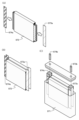
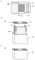
이차 전지의 제작 공정의 적어도 일부를 자동화한다. 신뢰성이 높은 이차 전지를 제공한다. 제 1 외장체 위에 제 1 전극을 배치하고, 제 1 전극 위에 세퍼레이터를 배치하고, 세퍼레이터 위에 제 2 전극을 배치하고, 제 1 전극, 세퍼레이터, 및 제 2 전극 중 적어도 하나에 전해질을 적하하고, 제 1 전극, 세퍼레이터, 및 제 2 전극 중 적어도 하나에 전해질을 함침시킨 후, 제 1 전극, 세퍼레이터, 및 제 2 전극을 덮도록 제 1 외장체 위에 제 2 외장체를 배치하고, 제 1 외장체 및 제 2 외장체에 의하여 제 1 전극, 세퍼레이터, 및 제 2 전극을 밀봉함으로써 이차 전지를 제작한다. 전해질은 적하되는 면에서의 최단 거리가 0mm보다 크고 1mm 이하인 위치에서 적하된다.At least a part of a secondary battery manufacturing process is automated. A highly reliable secondary battery is provided. Disposing a first electrode on the first exterior body, disposing a separator on the first electrode, disposing a second electrode on the separator, dropping an electrolyte onto at least one of the first electrode, the separator, and the second electrode; After impregnating at least one of the first electrode, the separator, and the second electrode with an electrolyte, a second exterior body is disposed on the first exterior body so as to cover the first electrode, the separator, and the second electrode, and the first exterior body and A secondary battery is produced by sealing the first electrode, the separator, and the second electrode with the second exterior body. The electrolyte is dropped from a position where the shortest distance from the dropping surface is greater than 0 mm and less than or equal to 1 mm.

Description
본 발명은 이차 전지 및 그 제작 방법에 관한 것이다. 또는 이차 전지를 가지는 휴대 정보 단말기, 차량 등에 관한 것이다. 또는 이차 전지의 제조 장치에 관한 것이다.The present invention relates to a secondary battery and a manufacturing method thereof. Or, it relates to a portable information terminal having a secondary battery, a vehicle, and the like. Or it relates to a manufacturing device for a secondary battery.
또한 본 발명의 일 형태는 상기 기술분야에 한정되지 않는다. 본 발명의 일 형태의 기술분야로서는 반도체 장치, 표시 장치, 발광 장치, 축전 장치, 기억 장치, 전자 기기, 조명 장치, 이들의 구동 방법, 또는 이들의 제조 방법을 일례로서 들 수 있다.Also, one embodiment of the present invention is not limited to the above technical fields. Examples of the technical field of one embodiment of the present invention include a semiconductor device, a display device, a light emitting device, a power storage device, a storage device, an electronic device, a lighting device, a driving method thereof, and a manufacturing method thereof.
또한 본 명세서 중에서 전자 기기란 축전 장치를 가지는 장치 전반을 가리키고, 축전 장치를 가지는 전기 광학 장치, 축전 장치를 가지는 정보 단말 장치 등은 모두 전자 기기이다.In this specification, electronic devices refer to devices having power storage devices in general, and electro-optical devices having power storage devices, information terminal devices having power storage devices, and the like are all electronic devices.
또한 본 명세서 중에서 축전 장치란, 축전 기능을 가지는 소자 및 장치 전반을 가리키는 것이다. 예를 들어 리튬 이온 이차 전지 등의 축전 장치(이차 전지라고도 함), 리튬 이온 커패시터, 및 전기 이중층 커패시터 등을 포함한다.In this specification, a power storage device refers to elements and devices having a power storage function in general. Examples include power storage devices such as lithium ion secondary batteries (also referred to as secondary batteries), lithium ion capacitors, and electric double layer capacitors.
근년 리튬 이온 이차 전지, 리튬 이온 커패시터, 공기 전지 등 여러 가지 축전 장치의 개발이 활발히 진행되고 있다. 특히, 고출력이고 에너지 밀도가 높은 리튬 이온 이차 전지는 휴대 전화기, 스마트폰, 또는 노트북형 컴퓨터 등의 휴대 정보 단말기, 휴대 음악 플레이어, 디지털 카메라, 의료 기기, 또는 하이브리드 자동차(HV), 전기 자동차(EV), 또는 플러그인 하이브리드 자동차(PHV) 등의 차세대 클린에너지 자동차 등, 반도체 산업의 발전과 함께 그 수요가 급속히 확대되고 있으며, 반복적으로 충전할 수 있는 에너지 공급원으로서 현대의 정보화 사회에 있어 불가결한 것이 되었다.In recent years, development of various power storage devices such as lithium ion secondary batteries, lithium ion capacitors, and air batteries has been actively progressed. In particular, lithium ion secondary batteries with high power and high energy density are portable information terminals such as mobile phones, smartphones, or notebook computers, portable music players, digital cameras, medical devices, hybrid vehicles (HV), electric vehicles (EV) ), or next-generation clean energy vehicles such as plug-in hybrid vehicles (PHVs), their demand is rapidly expanding along with the development of the semiconductor industry, and as an energy supply source that can be recharged repeatedly, it has become indispensable in the modern information society. .
리튬 이온 이차 전지는 코발트산 리튬(LiCoO2) 또는 인산 철 리튬(LiFePO4) 등의 양극 활물질을 포함하는 양극과, 리튬의 흡장·방출이 가능한 흡연 등의 탄소 재료 등의 음극 활물질을 포함하는 음극과, 에틸렌 카보네이트(EC) 또는 다이에틸카보네이트(DEC) 등의 유기 용매 등을 포함하는 전해질로 구성된다.A lithium ion secondary battery includes a positive electrode including a positive electrode active material such as lithium cobaltate (LiCoO 2 ) or lithium iron phosphate (LiFePO 4 ) and a negative electrode including a negative electrode active material such as a carbon material such as smoking capable of intercalating and releasing lithium. and an electrolyte including an organic solvent such as ethylene carbonate (EC) or diethyl carbonate (DEC).
또한 리튬 이온 이차 전지에는 고용량, 고성능, 및 다양한 동작 환경에서의 안전성 등이 요구되고 있다.In addition, lithium ion secondary batteries are required to have high capacity, high performance, and safety in various operating environments.
특허문헌 1에는 제조를 효율화할 수 있는 적층형 전지의 제조 장치가 개시(開示)되어 있다.
본 발명의 일 형태는 이차 전지의 제작 공정의 적어도 일부를 자동화하는 것을 과제 중 하나로 한다.One aspect of the present invention makes it one of the tasks to automate at least a part of a secondary battery manufacturing process.
본 발명의 일 형태는 크기가 비교적 큰 이차 전지의 제작 방법을 제공하는 것을 과제 중 하나로 한다.An object of one embodiment of the present invention is to provide a method for manufacturing a secondary battery having a relatively large size.
본 발명의 일 형태는 이차 전지를 효율적으로 단시간으로 제작하는 것을 과제 중 하나로 한다. 본 발명의 일 형태는 이차 전지를 높은 수율로 제작하는 것을 과제 중 하나로 한다. 본 발명의 일 형태는 제조 비용이 절감된 이차 전지의 제작 방법을 제공하는 것을 과제 중 하나로 한다.One aspect of the present invention makes it one of the problems to efficiently manufacture a secondary battery in a short time. In one embodiment of the present invention, one of the tasks is to manufacture a secondary battery with a high yield. An object of one embodiment of the present invention is to provide a manufacturing method of a secondary battery with a reduced manufacturing cost.
본 발명의 일 형태는 신뢰성이 높은 이차 전지의 제작 방법을 제공하는 것을 과제 중 하나로 한다. 본 발명의 일 형태는 안전성이 높은 이차 전지의 제작 방법을 제공하는 것을 과제 중 하나로 한다.An object of one embodiment of the present invention is to provide a method for manufacturing a highly reliable secondary battery. An object of one embodiment of the present invention is to provide a method for manufacturing a secondary battery with high safety.
또한 이들 과제의 기재는 다른 과제의 존재를 방해하는 것은 아니다. 본 발명의 일 형태는 이들 과제 모두를 반드시 해결할 필요는 없는 것으로 한다. 명세서, 도면, 청구항의 기재로부터 이들 외의 과제를 추출할 수 있다.In addition, the description of these subjects does not obstruct the existence of other subjects. In one embodiment of the present invention, it is not necessary to necessarily solve all of these problems. Subjects other than these can be extracted from the description of the specification, drawings, and claims.
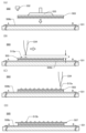
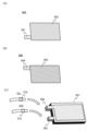
본 발명의 일 형태는 제 1 외장체 위에 제 1 전극을 배치하고, 제 1 전극 위에 세퍼레이터를 배치하고, 세퍼레이터 위에 제 2 전극을 배치하고, 제 1 전극, 세퍼레이터, 및 제 2 전극 중 적어도 하나에 전해질을 적하하고, 제 1 전극, 세퍼레이터, 및 제 2 전극 중 적어도 하나에 전해질을 함침(含浸)시킨 후, 제 1 전극, 세퍼레이터, 및 제 2 전극을 덮도록 제 1 외장체 위에 제 2 외장체를 배치하고, 제 1 외장체 및 제 2 외장체에 의하여 제 1 전극, 세퍼레이터, 및 제 2 전극을 밀봉하는, 이차 전지의 제작 방법이다. 제 1 전극 및 제 2 전극 중 한쪽이 양극이고 다른 쪽이 음극이다. 전해질은 적하되는 면에서의 최단 거리가 0mm보다 크고 1mm 이하인 위치에서 적하되는 것이 바람직하다.In one embodiment of the present invention, a first electrode is disposed on a first exterior body, a separator is disposed on the first electrode, a second electrode is disposed on the separator, and at least one of the first electrode, the separator, and the second electrode is disposed. After dropping the electrolyte and impregnating at least one of the first electrode, the separator, and the second electrode with the electrolyte, a second exterior body is placed on the first exterior body to cover the first electrode, the separator, and the second electrode. is disposed, and the first electrode, the separator, and the second electrode are sealed by the first exterior body and the second exterior body. One of the first electrode and the second electrode is an anode and the other is a cathode. The electrolyte is preferably dropped from a position where the shortest distance from the dropping surface is greater than 0 mm and less than 1 mm.
전해질은 0.3mPa·s 이상 100mPa·s 이하의 점도로 적하되는 것이 바람직하다.The electrolyte is preferably dripped at a viscosity of 0.3 mPa·s or more and 100 mPa·s or less.
전해질은 20℃이상 80℃이하의 온도로 적하되는 것이 바람직하다.The electrolyte is preferably added dropwise at a temperature of 20°C or more and 80°C or less.
전해질은 플루오린을 포함하는 것이 바람직하다.The electrolyte preferably contains fluorine.
전해질은 이온성 액체를 포함하는 것이 바람직하다.The electrolyte preferably contains an ionic liquid.
본 발명의 일 형태는 제 1 외장체 위에 제 1 전극을 배치하고, 제 1 전극에 제 1 전해질을 적하하고, 제 1 전극 위에 세퍼레이터를 배치하고, 세퍼레이터 위에 제 2 전해질을 적하하고, 세퍼레이터 위에 제 2 전극을 배치하고, 제 2 전극 위에 제 3 전해질을 적하하고, 제 1 전극, 세퍼레이터, 및 제 2 전극을 덮도록 제 1 외장체 위에 제 2 외장체를 배치하고, 제 1 외장체 및 제 2 외장체에 의하여 제 1 전극, 세퍼레이터, 및 제 2 전극을 밀봉하는, 이차 전지의 제작 방법이다. 제 1 전극 및 제 2 전극 중 한쪽이 양극이고 다른 쪽이 음극이다. 제 1 전해질은 제 1 전극에서의 최단 거리가 0mm보다 크고 1mm 이하인 위치에서 적하되는 것이 바람직하다. 제 2 전해질은 세퍼레이터에서의 최단 거리가 0mm보다 크고 1mm 이하인 위치에서 적하되는 것이 바람직하다. 제 3 전해질은 제 2 전극에서의 최단 거리가 0mm보다 크고 1mm 이하인 위치에서 적하되는 것이 바람직하다.In one embodiment of the present invention, a first electrode is disposed on a first exterior body, a first electrolyte is dropped onto the first electrode, a separator is disposed on the first electrode, a second electrolyte is dropped onto the separator, and a first electrolyte is dropped onto the separator. Dispose two electrodes, drop a third electrolyte onto the second electrode, dispose a second exterior body on the first exterior body so as to cover the first electrode, the separator, and the second electrode, and A method for manufacturing a secondary battery in which a first electrode, a separator, and a second electrode are sealed with an exterior body. One of the first electrode and the second electrode is an anode and the other is a cathode. The first electrolyte is preferably dripped at a position where the shortest distance from the first electrode is greater than 0 mm and less than or equal to 1 mm. The second electrolyte is preferably dropped at a position where the shortest distance in the separator is greater than 0 mm and less than or equal to 1 mm. Preferably, the third electrolyte is dropped at a position where the shortest distance from the second electrode is greater than 0 mm and less than or equal to 1 mm.
제 1 전해질, 제 2 전해질, 및 제 3 전해질은 각각 0.3mPa·s 이상 100mPa·s 이하의 점도로 적하되는 것이 바람직하다.The first electrolyte, the second electrolyte, and the third electrolyte are preferably dripped at a viscosity of 0.3 mPa·s or more and 100 mPa·s or less, respectively.
제 1 전해질, 제 2 전해질, 및 제 3 전해질은 각각 20℃이상 80℃이하의 온도로 적하되는 것이 바람직하다.It is preferable that the first electrolyte, the second electrolyte, and the third electrolyte are added dropwise at a temperature of 20° C. or more and 80° C. or less, respectively.
제 1 전해질, 제 2 전해질, 및 제 3 전해질은 각각 플루오린을 포함하는 것이 바람직하다.It is preferable that each of the first electrolyte, the second electrolyte, and the third electrolyte contain fluorine.
제 1 전해질, 제 2 전해질, 및 제 3 전해질은 각각 이온성 액체를 포함하는 것이 바람직하다.It is preferable that each of the first electrolyte, the second electrolyte, and the third electrolyte contain an ionic liquid.
제 1 전해질, 제 2 전해질, 및 제 3 전해질은 모두 동일한 재료인 것이 바람직하다.It is preferable that all of the first electrolyte, the second electrolyte, and the third electrolyte are the same material.
제 1 외장체는 오목부를 가지는 것이 바람직하다. 제 1 전극, 세퍼레이터, 및 제 2 전극은 오목부에 배치되는 것이 바람직하다.It is preferable that the 1st exterior body has a recessed part. The first electrode, the separator, and the second electrode are preferably disposed in the concave portion.
제 1 외장체 위에 수지층을 배치하는 것이 바람직하다. 제 2 외장체를 배치한 후, 감압하에서 수지층에 광을 조사함으로써 수지층의 적어도 일부를 경화시키는 것이 바람직하다. 밀봉은 광을 조사한 후, 대기압하에서 수행하는 것이 바람직하다. 수지층은 제 1 전극, 세퍼레이터, 및 제 2 전극을 둘러싸도록 테두리 형상으로 배치되는 것이 바람직하다.It is preferable to dispose a resin layer on the first exterior body. After disposing the second exterior body, it is preferable to cure at least a part of the resin layer by irradiating the resin layer with light under reduced pressure. The sealing is preferably performed under atmospheric pressure after irradiation with light. The resin layer is preferably arranged in a frame shape so as to surround the first electrode, the separator, and the second electrode.
광은 자외광인 것이 바람직하다.The light is preferably ultraviolet light.
밀봉은 수지층에 광을 조사하여, 수지층을 경화시킴으로써 수행되는 것이 바람직하다. 수지층은 감압하에서 광이 조사된 면적보다, 밀봉 시에 광이 조사된 면적이 더 넓은 것이 바람직하다. 또는 밀봉은 열 압착에 의하여 수행되는 것이 바람직하다.The sealing is preferably performed by curing the resin layer by irradiating the resin layer with light. It is preferable that the area of the resin layer irradiated with light during sealing is larger than the area irradiated with light under reduced pressure. Alternatively, sealing is preferably performed by thermal compression.
감압하에서 광을 조사하기 전에 제 1 전극에 제 1 리드 전극을 접속하는 공정과, 제 2 전극에 제 2 리드 전극을 접속하는 공정을 가지는 것이 바람직하다.It is preferable to have a step of connecting the first lead electrode to the first electrode and a step of connecting the second lead electrode to the second electrode before irradiating light under reduced pressure.
제 1 전극 및 제 2 전극 중 한쪽 또는 양쪽은 그래핀을 포함하는 것이 바람직하다.One or both of the first electrode and the second electrode preferably includes graphene.
제 1 전극은 제 1 집전체의 한쪽 면 또는 양쪽 면에 제 1 활물질층을 가지는 것이 바람직하다.The first electrode preferably has a first active material layer on one side or both sides of the first current collector.
제 2 전극은 제 2 집전체의 한쪽 면 또는 양쪽 면에 제 2 활물질층을 가지는 것이 바람직하다.The second electrode preferably has a second active material layer on one side or both sides of the second current collector.
본 발명의 일 형태는 제 1 외장체와 제 2 외장체 사이에 양극, 세퍼레이터, 및 음극을 각각 하나 이상 가지는 적층체가 제공된 이차 전지의 제조 장치이다. 상기 제조 장치는 반송실, 제 1 처리실, 및 제 2 처리실을 가진다. 반송실은 제작 중의 이차 전지를 제 1 처리실에서 제 2 처리실로 반송하는 기능을 가진다. 제 1 처리실은 제 1 스테이지, 흡착 기구, 및 전해질 적하 기구를 가진다. 제 1 스테이지는 제작 중의 이차 전지를 지지하는 기능을 가진다. 흡착 기구는 적층체를 구성하는 부재를 흡착하고 제 1 외장체 위에 배치하는 기능을 가진다. 전해질 적하 기구는 적층체를 구성하는 부재 위에, 적하되는 면에서의 최단 거리가 0mm보다 크고 1mm 이하인 위치에서 전해질을 적하하는 기능을 가진다. 제 2 처리실은 제 1 외장체 및 제 2 외장체에 의하여 양극, 세퍼레이터, 및 음극을 밀봉하는 기능을 가진다.One aspect of the present invention is an apparatus for manufacturing a secondary battery in which a laminate having at least one anode, separator, and at least one anode, respectively, is provided between a first exterior body and a second exterior body. The manufacturing apparatus has a transfer chamber, a first processing chamber, and a second processing chamber. The transport chamber has a function of transporting the secondary battery being manufactured from the first processing chamber to the second processing chamber. The first processing chamber has a first stage, an adsorption mechanism, and an electrolyte dripping mechanism. The first stage has a function of supporting the secondary battery being manufactured. The adsorbing mechanism has a function of adsorbing the member constituting the laminate and arranging it on the first exterior body. The electrolyte dropping mechanism has a function of dropping the electrolyte on a member constituting the laminate at a position where the shortest distance from the dropping surface is greater than 0 mm and less than or equal to 1 mm. The second processing chamber has a function of sealing the positive electrode, the separator, and the negative electrode by the first external body and the second external body.
흡착 기구는 제 1 외장체를 흡착하고 제 1 스테이지 위에 배치하는 기능을 가지는 것이 바람직하다.The adsorption mechanism preferably has a function of adsorbing the first exterior body and disposing it on the first stage.
제 1 처리실은 불활성 가스 공급 기구를 가지는 것이 바람직하다. 불활성 가스 공급 기구는 제 1 처리실의 내부에 불활성 가스를 공급하는 기능을 가지는 것이 바람직하다.The first processing chamber preferably has an inert gas supply mechanism. The inert gas supply mechanism preferably has a function of supplying an inert gas into the first processing chamber.
불활성 가스는 아르곤 가스인 것이 바람직하다.The inert gas is preferably argon gas.
제 1 처리실은 밀봉 재료 공급 기구를 가지는 것이 바람직하다. 밀봉 재료 공급 기구는 제 1 외장체 위에 수지층을 형성하는 기능을 가지는 것이 바람직하다. 제 2 처리실은 배기 기구 및 광 조사 기구를 가지는 것이 바람직하다. 배기 기구는 제 2 처리실 내부를 감압하는 기능을 가지는 것이 바람직하다. 광 조사 기구는 수지층의 적어도 일부에 광을 조사하는 기능을 가지는 것이 바람직하다.It is preferable that the 1st processing chamber has a sealing material supply mechanism. The sealing material supply mechanism preferably has a function of forming a resin layer on the first exterior body. The second processing chamber preferably has an exhaust mechanism and a light irradiation mechanism. The exhaust mechanism preferably has a function of depressurizing the inside of the second processing chamber. The light irradiation mechanism preferably has a function of irradiating light to at least a part of the resin layer.
본 발명의 일 형태에 의하여 이차 전지의 제작 공정의 적어도 일부를 자동화할 수 있다.According to one embodiment of the present invention, at least a part of a secondary battery manufacturing process can be automated.
본 발명의 일 형태에 의하여 크기가 비교적 큰 이차 전지의 제작 방법을 제공할 수 있다. 대용량의 이차 전지를 탑재하는 경우, 소형의 이차 전지를 탑재하는 경우보다 탑재하는 이차 전지의 개수를 줄일 수 있다. 탑재하는 이차 전지의 개수를 줄임으로써, 각각의 전지의 제어가 용이해져, 충전 제어 회로의 부담이 경감된다.According to one embodiment of the present invention, a method for manufacturing a secondary battery having a relatively large size can be provided. In the case of mounting a large-capacity secondary battery, the number of secondary batteries to be mounted can be reduced compared to the case of mounting a small-sized secondary battery. By reducing the number of secondary batteries to be mounted, control of each battery becomes easy, and the load on the charge control circuit is reduced.
본 발명의 일 형태의 이차 전지의 제작 방법에서는 복수의 이차 전지의 밀봉 공정을 한번에 수행할 수 있기 때문에, 이차 전지의 제작 공정을 대폭 단축할 수 있다. 따라서, 이차 전지의 제조 비용을 절감할 수 있다. 또한 이차 전지를 효율적으로 단시간으로 제작할 수 있다. 또한 이차 전지를 높은 수율로 제작할 수 있다.In the secondary battery manufacturing method of one embodiment of the present invention, since the sealing process of a plurality of secondary batteries can be performed at once, the secondary battery manufacturing process can be significantly shortened. Thus, the manufacturing cost of the secondary battery can be reduced. In addition, the secondary battery can be produced efficiently and in a short time. In addition, the secondary battery can be manufactured with high yield.
본 발명의 일 형태에 의하여 신뢰성이 높은 이차 전지의 제작 방법을 제공할 수 있다. 또한 본 발명의 일 형태에 의하여 안전성이 높은 이차 전지의 제작 방법을 제공할 수 있다.According to one embodiment of the present invention, a method for manufacturing a highly reliable secondary battery can be provided. In addition, according to one embodiment of the present invention, a method for manufacturing a secondary battery with high safety can be provided.
또한 이들 효과의 기재는 다른 효과의 존재를 방해하는 것은 아니다. 본 발명의 일 형태는 반드시 이들 효과 모두를 가질 필요는 없다. 명세서, 도면, 청구항의 기재로부터 이들 외의 효과를 추출할 수 있다.In addition, the description of these effects does not prevent the existence of other effects. One embodiment of the present invention does not necessarily have all of these effects. Effects other than these can be extracted from the description of the specification, drawings, and claims.
도 1의 (A)는 전기 자동차에 탑재된 이차 전지의 일례를 나타낸 도면이다. 도 1의 (B)는 전극에 전해질을 적하한 후의 상태를 설명하는 상면도이다.
도 2는 이차 전지의 제조 장치의 일례를 나타낸 상면도이다.
도 3은 이차 전지의 제작 방법의 일례를 나타낸 흐름도이다.
도 4는 이차 전지의 제작 방법의 일례를 나타낸 흐름도이다.
도 5의 (A) 내지 (D)는 이차 전지의 제작 방법의 일례를 나타낸 단면도이다.
도 6의 (A) 및 (B)는 이차 전지의 제작 방법의 일례를 나타낸 단면도이다.
도 7의 (A) 및 (B)는 다면취(多面取)에 대하여 설명하는 상면도이다. 도 7의 (C)는 이차 전지의 제작 방법의 일례를 나타낸 단면도이다.
도 8은 이차 전지의 제작 방법의 일례를 나타낸 사시도이다.
도 9의 (A) 및 (B)는 이차 전지의 제작 방법의 일례를 나타낸 사시도이다.
도 10의 (A) 및 (B)는 이차 전지의 제작 방법의 일례를 나타낸 사시도이다.
도 11의 (A)는 이차 전지의 제작 방법의 일례를 나타낸 상면도이다. 도 11의 (B)는 제작 중의 이차 전지의 일례를 나타낸 단면도이다. 도 11의 (C)는 제작 중의 이차 전지의 일례를 나타낸 상면도이다.
도 12의 (A) 및 (B)는 이차 전지의 제작 방법의 일례를 나타낸 상면도이다.
도 13은 이차 전지의 제작 방법의 일례를 나타낸 상면도이다.
도 14는 이차 전지의 제작 방법의 일례를 나타낸 상면도이다.
도 15의 (A) 내지 (D)는 집전체의 일례를 나타낸 상면도이다.
도 16은 양극 활물질의 결정 구조를 설명하는 도면이다.
도 17은 양극 활물질의 결정 구조를 설명하는 도면이다.
도 18의 (A) 내지 (C)는 이차 전지의 외관의 일례를 나타낸 도면이다.
도 19의 (A) 및 (B)는 이차 전지의 외관의 일례를 나타낸 도면이다.
도 20의 (A) 내지 (C)는 이차 전지의 제작 방법의 일례를 나타낸 도면이다.
도 21은 이차 전지의 일례를 나타낸 단면도이다.
도 22의 (A)는 이차 전지의 일례를 나타낸 도면이다. 도 22의 (B) 및 (C)는 적층체의 제작 방법의 일례를 나타낸 도면이다.
도 23의 (A) 내지 (C)는 이차 전지의 제작 방법의 일례를 나타낸 도면이다.
도 24의 (A) 및 (B)는 전극 조립체의 일례를 나타낸 단면도이다. 도 24의 (C)는 이차 전지의 일례를 나타낸 단면도이다.
도 25의 (A) 및 (B)는 이차 전지의 일례를 나타낸 도면이다. 도 25의 (C)는 이차 전지의 내부의 상태를 나타낸 도면이다.
도 26의 (A) 내지 (C)는 이차 전지의 일례를 나타낸 도면이다.
도 27의 (A)는 전지 팩의 일례를 나타낸 사시도이다. 도 27의 (B)는 전지 팩의 일례를 나타낸 블록도이다. 도 27의 (C)는 모터를 가지는 차량의 일례를 나타낸 블록도이다.
도 28의 (A) 내지 (D)는 수송용 차량의 일례를 나타낸 도면이다.
도 29의 (A) 및 (B)는 축전 장치의 일례를 나타낸 도면이다.
도 30의 (A) 내지 (E)는 전자 기기의 일례를 나타낸 도면이다.
도 31의 (A)는 실시예의 실험 방법에 대하여 설명하는 도면이다. 도 31의 (B) 내지 (E)는 실시예의 실험 결과에 대하여 설명하는 도면이다.1(A) is a diagram showing an example of a secondary battery mounted in an electric vehicle. Fig. 1(B) is a top view for explaining the state after dropping the electrolyte on the electrode.
2 is a top view showing an example of a manufacturing apparatus for a secondary battery.
3 is a flowchart showing an example of a method for manufacturing a secondary battery.
4 is a flowchart showing an example of a method for manufacturing a secondary battery.
5(A) to (D) are cross-sectional views showing an example of a method for manufacturing a secondary battery.
6(A) and (B) are cross-sectional views showing an example of a method for manufacturing a secondary battery.
7(A) and (B) are top views illustrating the multi-faceted appearance. 7(C) is a cross-sectional view showing an example of a method for manufacturing a secondary battery.
8 is a perspective view showing an example of a method for manufacturing a secondary battery.
9(A) and (B) are perspective views showing an example of a method for manufacturing a secondary battery.
10(A) and (B) are perspective views showing an example of a method for manufacturing a secondary battery.
11(A) is a top view showing an example of a method for manufacturing a secondary battery. 11(B) is a cross-sectional view showing an example of a secondary battery being manufactured. 11(C) is a top view showing an example of a secondary battery being manufactured.
12(A) and (B) are top views showing an example of a method for manufacturing a secondary battery.
13 is a top view showing an example of a method for manufacturing a secondary battery.
14 is a top view showing an example of a method for manufacturing a secondary battery.
15(A) to (D) are top views showing an example of a current collector.
16 is a diagram explaining the crystal structure of the positive electrode active material.
17 is a diagram explaining the crystal structure of a positive electrode active material.
18(A) to (C) are diagrams showing examples of external appearances of secondary batteries.
19(A) and (B) are views showing an example of the appearance of a secondary battery.
20(A) to (C) are views showing an example of a method for manufacturing a secondary battery.
21 is a cross-sectional view showing an example of a secondary battery.
22(A) is a diagram showing an example of a secondary battery. 22(B) and (C) are views showing an example of a method for manufacturing a laminate.
23(A) to (C) are views showing an example of a method for manufacturing a secondary battery.
24 (A) and (B) are cross-sectional views showing an example of an electrode assembly. 24(C) is a cross-sectional view showing an example of a secondary battery.
25(A) and (B) are views showing an example of a secondary battery. 25(C) is a diagram showing the internal state of the secondary battery.
26(A) to (C) are diagrams showing an example of a secondary battery.
Fig. 27(A) is a perspective view showing an example of a battery pack. 27(B) is a block diagram showing an example of a battery pack. 27(C) is a block diagram showing an example of a vehicle having a motor.
28(A) to (D) are diagrams showing an example of a transportation vehicle.
29(A) and (B) are diagrams showing an example of a power storage device.
30 (A) to (E) are diagrams showing an example of an electronic device.
Fig. 31 (A) is a diagram explaining the experimental method of the embodiment. 31 (B) to (E) are diagrams for explaining the experimental results of Examples.
실시형태에 대하여 도면을 사용하여 자세히 설명한다. 다만, 본 발명은 이하의 설명에 한정되지 않고, 본 발명의 취지 및 그 범위에서 벗어남이 없이 그 형태 및 자세한 사항을 다양하게 변경할 수 있다는 것은 통상의 기술자라면 쉽게 이해할 수 있다. 따라서 본 발명은 이하에 기재하는 실시형태의 내용에 한정하여 해석되는 것은 아니다.Embodiments will be described in detail using drawings. However, the present invention is not limited to the following description, and it is easily understood by those skilled in the art that the form and details can be variously changed without departing from the spirit and scope of the present invention. Therefore, this invention is limited to the content of embodiment described below, and is not interpreted.
또한 이하에서 설명하는 발명의 구성에서, 동일한 부분 또는 같은 기능을 가지는 부분에는 동일한 부호를 상이한 도면 사이에서 공통적으로 사용하고, 그 반복 설명은 생략한다. 또한 같은 기능을 가지는 부분을 가리키는 경우에는, 같은 해치 패턴으로 하고, 특별히 부호를 붙이지 않는 경우가 있다.In the configuration of the invention described below, the same reference numerals are commonly used in different drawings for the same parts or parts having the same functions, and repeated explanations thereof are omitted. In addition, when indicating parts having the same function, the same hatch pattern may be used and no special code is attached.
또한 도면에서 나타내는 각 구성의 위치, 크기, 및 범위 등은 이해를 용이하게 하기 위하여 실제의 위치, 크기, 및 범위 등을 나타내지 않는 경우가 있다. 그러므로 개시하는 발명은 반드시 도면에 개시된 위치, 크기, 및 범위 등에 한정되지 않는다.In addition, the position, size, range, etc. of each component shown in the drawings may not indicate the actual position, size, range, etc. for easy understanding. Therefore, the disclosed invention is not necessarily limited to the position, size, range, etc. disclosed in the drawings.
또한 '막'이라는 용어와 '층'이라는 용어는 경우에 따라 또는 상황에 따라 서로 바꿀 수 있다. 예를 들어 '도전층'이라는 용어를 '도전막'이라는 용어로 변경할 수 있다. 또는 예를 들어 '절연막'이라는 용어를 '절연층'이라는 용어로 변경할 수 있다.In addition, the terms 'film' and 'layer' may be interchanged depending on the case or circumstances. For example, the term 'conductive layer' may be changed to the term 'conductive layer'. Alternatively, for example, the term 'insulating layer' may be changed to the term 'insulating layer'.
(실시형태 1)(Embodiment 1)
본 실시형태에서는 본 발명의 일 형태의 이차 전지의 제작 방법에 대하여 도 1 내지 도 14를 사용하여 설명한다.In this embodiment, a method for manufacturing a secondary battery of one embodiment of the present invention will be described using FIGS. 1 to 14 .
이차 전지의 제작 공정에서는 양극, 세퍼레이터, 및 음극을 가지는 적층체를 캔 또는 봉투 형상의 외장체에 넣은 후에 전해액을 주입하고 나서 밀봉하는 경우가 많다. 이와 같은 방법에서는 양극 및 음극의 내부까지 전해질이 함침되는 데 걸리는 시간이 길어지는 경우가 있다. 또한 이와 같은 방법에서는 양극 및 음극의 내부로의 전해질의 함침이 불충분해지는 경우가 있다. 또한 이와 같은 방법에서는 리튬 이온이 주입구로부터 외쪽으로 확산될 우려가 있다. 또한 이와 같은 방법은 공정 수가 많아지기 쉽다. 또한 전해액을 주입하는 양을 높은 정밀도로 조절하기 어려운 경우가 있다. 이차 전지에 필요한 양의 전해액을 정확하게 제공하는 것이, 균일한 특성을 가지는 이차 전지의 대량 생산으로 이어진다고 할 수 있다.In the manufacturing process of a secondary battery, in many cases, a laminate having a positive electrode, a separator, and a negative electrode is placed in a can or bag-shaped exterior body, then an electrolyte solution is injected and then sealed. In such a method, the time required for the electrolyte to be impregnated to the inside of the positive electrode and the negative electrode may be long. In addition, in such a method, the impregnation of the electrolyte into the inside of the positive electrode and the negative electrode may become insufficient in some cases. Also, in this method, there is a possibility that lithium ions may diffuse outward from the injection port. In addition, such a method tends to increase the number of steps. In addition, there are cases in which it is difficult to control the amount of electrolyte to be injected with high precision. It can be said that providing an accurate amount of electrolyte required for a secondary battery leads to mass production of secondary batteries having uniform characteristics.
본 발명의 일 형태의 이차 전지의 제작 방법에서는 제 1 외장체 위에 제 1 전극을 배치하고, 제 1 전극 위에 세퍼레이터를 배치하고, 세퍼레이터 위에 제 2 전극을 배치하고, 배치된 제 1 전극, 세퍼레이터, 및 제 2 전극 중 적어도 하나에 전해질을 적하한다. 전해질을 몇 방울 적하함으로써 제 1 전극, 세퍼레이터, 또는 제 2 전극에 전해질을 균일하게 또는 충분히 함침시킬 수 있다.In the method for manufacturing a secondary battery of one embodiment of the present invention, a first electrode is disposed on a first exterior body, a separator is disposed on the first electrode, a second electrode is disposed on the separator, and the disposed first electrode, separator, and the electrolyte is dropped onto at least one of the second electrodes. By dropping a few drops of the electrolyte, the first electrode, the separator, or the second electrode can be uniformly or sufficiently impregnated with the electrolyte.
여기서 예를 들어 제 1 전극에 전해질을 적하할 때, 전해질을 적하하는 노즐이 제 1 전극과 접촉되면, 전해질의 적하가 어려워진다. 또한 노즐이 제 1 전극에서 지나치게 떨어지면, 소정의 시간 내에 전해질의 일부 또는 모두를 적하할 수 없게 될 우려가 있다. 이에 의하여 적하 위치가 어긋나거나, 적하량이 불균일하게 되는 등의 문제가 발생되는 경우가 있다. 그러므로 전해질을 적하할 때는 적하되는 면에서의 최단 거리가 0mm보다 크고 1mm 이하인 위치에서 전해질을 적하하는 것이 바람직하다. 적하되는 면은 적하 대상(예를 들어, 제 1 전극, 세퍼레이터, 또는 제 2 전극)의 표면이라고 할 수도 있다.Here, for example, when dripping the electrolyte onto the first electrode, if the nozzle through which the electrolyte drips comes into contact with the first electrode, dripping of the electrolyte becomes difficult. Further, if the nozzle is excessively separated from the first electrode, there is a risk that part or all of the electrolyte may not be dripped within a predetermined time. This may cause problems such as displacement of the dropping position or non-uniform dripping amount. Therefore, when dropping the electrolyte, it is preferable to drop the electrolyte at a position where the shortest distance from the dropping surface is greater than 0 mm and less than 1 mm. The surface on which the drop is dropped can also be referred to as the surface of the drop target (for example, the first electrode, the separator, or the second electrode).
본 발명의 일 형태의 이차 전지의 제작 방법에서는 제 1 전극, 세퍼레이터, 및 제 2 전극 중 어느 하나 또는 복수에 대하여 전해질을 몇 방울 적하하고, 전해질을 함침시킨 후, 제 1 전극, 세퍼레이터, 및 제 2 전극의 적층 구조(이하, 적층체라고도 함)를 제 1 외장체 및 제 2 외장체에 의하여 밀봉한다. 예를 들어 박형(래미네이트형) 이차 전지의 경우, 제 1 외장체와 제 2 외장체의 외측 단부(이차 전지의 형상이 얇은 직방체인 경우, 상면에서 보았을 때의 사변)를 빈틈없이 밀봉한다. 밀봉 방법으로서는 스지층에 광을 조사하는 방법, 외장체를 열 압착하는 방법 등을 사용할 수 있다.In the method for manufacturing a secondary battery of one embodiment of the present invention, a few drops of an electrolyte are dropped onto any one or a plurality of the first electrode, the separator, and the second electrode, impregnated with the electrolyte, and then the first electrode, the separator, and the second electrode. A laminated structure of two electrodes (hereinafter also referred to as a laminate) is sealed by a first exterior body and a second exterior body. For example, in the case of a thin (laminated) secondary battery, the outer ends of the first exterior body and the second exterior body (if the shape of the secondary battery is a thin rectangular parallelepiped, oblique sides when viewed from the top) are tightly sealed. As the sealing method, a method of irradiating light to the paper layer, a method of thermocompressing the exterior body, and the like can be used.
본 명세서 등에서 밀봉이란 어떤 밀폐 영역을 외기와 차단하는 것을 가리키고, 이차 전지에 있어서는 적층체 및 그 주변을 밀폐 영역으로 하고 밀폐 영역의 외측을 외장체로 둘러싸 외기와 차단하는 것을 말한다. 또한 밀봉 후에는 외장체의 단부를 구부려 밀봉 강도를 상승시켜, 외부로부터의 불순물 침입 또는 내부로부터의 가스 등의 방출을 방지한다.In this specification and the like, sealing refers to blocking a certain sealed area from outside air, and in the case of a secondary battery, the laminate and its surroundings are used as a sealed area, and the outside of the sealed area is surrounded by an exterior body to block outside air. In addition, after sealing, the edge of the exterior body is bent to increase the sealing strength, thereby preventing the intrusion of impurities from the outside or the release of gas or the like from the inside.
밀봉은 대기압하(대기압 분위기하, 상압하라고도 함)에서도 수행할 수 있고, 이 경우에는 아르곤 분위기하 또는 질소 분위기하 등의 불활성 분위기하에서 수행한다. 감압하(감압 분위기하라고도 함)에서 밀봉을 수행하면, 외장체로 둘러싸인 밀폐 영역에 불순물 및 공기가 들어가기 어려우므로 바람직하다.Sealing can be performed even under atmospheric pressure (atmospheric pressure atmosphere, also referred to as atmospheric pressure), and in this case, it is performed under an inert atmosphere such as an argon atmosphere or a nitrogen atmosphere. Sealing under reduced pressure (also referred to as a reduced pressure atmosphere) is preferable because it is difficult for impurities and air to enter the sealed area enclosed by the exterior body.
예를 들어 감압하에서 광 경화 수지를 사용하여 밀봉을 수행하여도 좋다. 우선 제 1 외장체 위에 테두리 형상의 수지층을 배치한다. 수지층에는 광 경화 수지를 사용하는 것이 바람직하다. 또한 적층체를 덮도록 제 1 외장체 위에 제 2 외장체를 배치하고, 감압하에서 수지층에 광을 조사함으로써, 수지층의 적어도 일부를 경화시킨다. 제 1 외장체 및 제 2 외장체에는 각각 외장 필름을 사용하는 것이 바람직하다.For example, sealing may be performed using a photocurable resin under reduced pressure. First, a frame-shaped resin layer is disposed on the first exterior body. It is preferable to use photocurable resin for the resin layer. Further, a second exterior body is disposed on the first exterior body so as to cover the laminate, and at least a part of the resin layer is cured by irradiating the resin layer with light under reduced pressure. It is preferable to use an exterior film for each of the first exterior body and the second exterior body.
대기압보다 감압된 분위기하에서 수지층의 적어도 일부를 경화시킨 후, 제작 중의 이차 전지를 대기압하에 노출시킴으로써 제 1 외장체와 제 2 외장체가 대기압으로 가압된다. 이에 의하여 제 1 외장체, 제 2 외장체, 및 테두리 형상의 수지층으로 둘러싸인 공간의 감압 상태가 유지된다. 따라서 불순물이 이차 전지 내에 혼입되는 것을 억제할 수 있다.After at least a part of the resin layer is cured in an atmosphere at a pressure lower than atmospheric pressure, the secondary battery under manufacture is exposed to atmospheric pressure so that the first exterior body and the second exterior body are pressurized to atmospheric pressure. As a result, the pressure-reduced state of the space surrounded by the first exterior body, the second exterior body, and the frame-shaped resin layer is maintained. Therefore, it is possible to suppress impurities from entering the secondary battery.
또한 적하한 전해질은 감압 분위기에서부터 대기압 분위기에 노출됨으로써 단기산으로 넓게 부재에 침투시킬 수 있다. 따라서, 전해질이 양극 및 음극의 표면, 나아가서는 내부까지 함침되는 데 걸리는 시간을 단축할 수 있다. 그리고, 양극 및 음극의 내부에 전해질을 충분히 함침시킬 수 있다.In addition, the dripped electrolyte can permeate the member widely in a short period of time by exposing from a reduced pressure atmosphere to an atmospheric pressure atmosphere. Accordingly, it is possible to shorten the time required for the electrolyte to impregnate the surfaces of the positive electrode and the negative electrode, and even to the inside. In addition, the inside of the positive electrode and the negative electrode may be sufficiently impregnated with an electrolyte.
또한 외부 추출을 위한 단자로서 기능하는 리드 전극(인출 배선 또는 리드 단자라고도 함)은 외장체의 외측으로 돌출되는 것으로 한다. 리드 전극은 이차 전지의 양극 또는 음극을 외장체의 외측으로 인출하기 위하여 제공된다.In addition, a lead electrode (also referred to as a lead wire or lead terminal) serving as a terminal for external extraction protrudes outward from the exterior body. The lead electrode is provided to lead the positive or negative electrode of the secondary battery to the outside of the exterior body.
또한 열 압착 또는 용착(융착, 열 접착 등이라고도 함)에 의하여 적층체를 밀봉하여도 좋다. 또한 광 조사에 의한 밀봉과 열에 의한 밀봉의 양쪽을 수행하여도 좋다. 또한 감압하에서 광을 조사하여 수지층의 일부를 경화시킨 후, 대기압하에서 광을 조사함으로써 수지층의 미경화 부분을 경화시켜도 좋다.Alternatively, the laminate may be sealed by thermal compression or welding (also referred to as fusion or thermal bonding). Further, both sealing by light irradiation and sealing by heat may be performed. Alternatively, after curing a part of the resin layer by irradiating light under reduced pressure, the uncured portion of the resin layer may be cured by irradiating light under atmospheric pressure.
감압하 또는 대기압하에서 광을 조사하여 수지층을 경화시키는 공정은 이차 전지를 고온에 노출시킬 필요가 없기 때문에, 이차 전지의 열화를 억제하여 이차 전지의 신뢰성을 높일 수 있다.Since the process of curing the resin layer by irradiating light under reduced pressure or atmospheric pressure does not require exposing the secondary battery to high temperatures, deterioration of the secondary battery can be suppressed and reliability of the secondary battery can be improved.
본 발명의 일 형태의 이차 전지의 제작 방법은 적어도 제 1 외장체 위에 적층체를 형성하는 공정부터 감압하에서 수지층을 경화시키는 공정까지를 하나의 장치로 연속적으로 수행할 수 있기 때문에, 불순물이 이차 전지 내에 혼입되는 것을 억제할 수 있다.In the method for manufacturing a secondary battery of one embodiment of the present invention, since the process of forming a laminate on at least the first exterior body and the process of curing the resin layer under reduced pressure can be continuously performed with one device, impurities are not removed from the secondary battery. Contamination in the battery can be suppressed.
또한 제 1 전극 및 제 2 전극 중 한쪽이 양극이고 다른 쪽이 음극이다. 적층체는 양극, 세퍼레이터, 및 음극의 순서로 적층된 것이어도 좋고, 음극, 세퍼레이터, 및 양극의 순서로 적층된 것이어도 좋다. 또한 세퍼레이터는 양극과 음극의 단락 방지를 위하여 사용한다. 이차 전지의 용량을 크게 하기 위하여 양극 및 음극을 복수로 적층하는 구성으로 하는 경우에는, 부품 점수를 삭감하기 위하여 하나의 공통된 세퍼레이터를 구부려 사용하는 구성으로 하여도 좋다.Moreover, one of the 1st electrode and the 2nd electrode is an anode, and the other is a cathode. The laminate may be one in which an anode, a separator, and a cathode are laminated in this order, or a cathode, a separator, and an anode are laminated in that order. Also, a separator is used to prevent a short circuit between the anode and the cathode. In the case where a plurality of positive and negative electrodes are laminated in order to increase the capacity of the secondary battery, a common separator may be bent and used in order to reduce the number of parts.
또한 본 발명의 일 형태의 이차 전지의 제작 방법에서는 제 1 외장체 위에 복수의 적층체를 배치하여도 좋다. 이때, 수지층으로서는 복수의 적층체 모두를 둘러싸는 하나의 테두리 형상의 수지층을 형성하여도 좋고, 하나 또는 복수의 적층체를 둘러싸는 테두리 형상의 수지층을 복수로 형성하여도 좋다. 예를 들어, 하나의 적층체당 하나의 테두리 형상의 수지층을 형성하여도 좋다. 또한 복수의 적층체를 덮도록 제 1 외장체 위에 제 2 외장체를 배치한다. 그리고 감압하에서 수지층에 대하여 광을 조사하고, 대기압하에서 제 1 외장체 및 제 2 외장체에 의하여 복수의 적층체를 밀봉한다. 밀봉 후, 제 1 외장체 및 제 2 외장체를 분단하여 적층체를 가지는 이차 전지를 따로 분리한다.Further, in the secondary battery manufacturing method of one embodiment of the present invention, a plurality of laminates may be disposed on the first exterior body. At this time, as the resin layer, one frame-shaped resin layer surrounding all of the plurality of laminates may be formed, or a plurality of frame-shaped resin layers surrounding one or a plurality of laminates may be formed. For example, you may form one edge-shaped resin layer per one laminated body. Further, a second exterior body is disposed on the first exterior body so as to cover the plurality of laminated bodies. Then, the resin layer is irradiated with light under reduced pressure, and the plurality of laminates are sealed by the first exterior body and the second exterior body under atmospheric pressure. After sealing, the first exterior body and the second exterior body are divided to separately separate the secondary battery having the laminated body.
수지층의 재료에는 자외광 경화 수지 등의 광 경화 수지(광 경화형 접착제 등이라고도 함), 열 경화 수지(열 경화형 접착제라고도 함), 반응 경화형 접착제, 혐기성 접착제 등의 각종 경화형 접착제를 사용할 수 있다. 이들 접착제로서는 에폭시 수지, 아크릴 수지, 실리콘(silicone) 수지, 페놀 수지, 폴리이미드 수지, 이미드 수지, PVC(폴리바이닐클로라이드) 수지, PVB(폴리바이닐뷰티랄) 수지, EVA(에틸렌바이닐아세테이트) 수지 등을 들 수 있다. 특히 에폭시 수지 등 가스 배리어성이 높은 재료가 바람직하다. 또한 2액 혼합형 수지를 사용하여도 좋다.As the material of the resin layer, various curable adhesives such as photocurable resins such as ultraviolet light curable resins (also referred to as photocurable adhesives, etc.), thermosetting resins (also referred to as thermocurable adhesives), reaction curable adhesives, and anaerobic adhesives can be used. Examples of these adhesives include epoxy resins, acrylic resins, silicone resins, phenol resins, polyimide resins, imide resins, PVC (polyvinyl chloride) resins, PVB (polyvinyl butyral) resins, and EVA (ethylene vinyl acetate) resins. etc. can be mentioned. In particular, a material having high gas barrier properties such as an epoxy resin is preferable. Also, a two-component mixed type resin may be used.
각종 광 경화 수지를 사용하는 경우에는 감압하에서 수지층에 광을 조사함으로써 수지층의 적어도 일부를 경화시킬 수 있다. 이에 의하여, 제작 중의 이차 전지를 대기압하에 노출시켜도 제 1 외장체, 제 2 외장체, 및 테두리 형상의 수지층으로 둘러싸인 공간의 감압 상태가 유지된다. 따라서 불순물이 이차 전지 내에 혼입되는 것을 억제할 수 있다. 광 경화 수지를 사용하면 수지층을 경화시킬 때 이차 전지를 고온에 노출시킬 필요가 없기 때문에, 이차 전지의 열화를 억제하여 신뢰성이 높은 이차 전지를 제작할 수 있다.In the case of using various photocurable resins, at least a part of the resin layer can be cured by irradiating the resin layer with light under reduced pressure. In this way, even if the secondary battery under manufacture is exposed to atmospheric pressure, the reduced pressure state of the space surrounded by the first exterior body, the second exterior body, and the frame-shaped resin layer is maintained. Therefore, it is possible to suppress impurities from entering the secondary battery. When the photocurable resin is used, it is not necessary to expose the secondary battery to a high temperature when curing the resin layer, so that a highly reliable secondary battery can be manufactured by suppressing deterioration of the secondary battery.
또한 열 경화 수지를 사용하는 경우에는 감압하에서 열 압착 또는 용착을 수행하는 것이 바람직하다. 이에 의하여 제작 중의 이차 전지를 대기압하에 노출시켜도 제 1 외장체, 제 2 외장체, 및 테두리 형상의 수지층으로 둘러싸인 공간의 감압 상태가 유지된다. 따라서 불순물이 이차 전지 내에 혼입되는 것을 억제할 수 있다. 열 경화 수지를 사용하면 광 조사 장치를 도입할 필요가 없기 때문에, 장치 도입을 위한 비용을 절감할 수 있는 경우가 있다.Also, in the case of using a thermosetting resin, it is preferable to perform thermal compression or welding under reduced pressure. In this way, even if the secondary battery being manufactured is exposed to atmospheric pressure, the reduced pressure state of the space surrounded by the first exterior body, the second exterior body, and the frame-shaped resin layer is maintained. Therefore, it is possible to suppress impurities from entering the secondary battery. Since there is no need to introduce a light irradiation device when a thermosetting resin is used, the cost for introducing the device can be reduced in some cases.
또한 감압하에서 열 압착 또는 용착을 수행하는 경우, 수지층을 형성하는 공정을 하지 않아도 되는 경우가 있다. 예를 들어 외장 필름의 내면의 수지(열가소성 필름 재료 등)를 사용하여 열 압착 또는 용착함으로써 제 1 외장체, 제 2 외장체, 및 테두리 형상의 수지층으로 둘러싸인 공간의 감압 상태를 대기압하에서 유지할 수 있는 경우가 있다. 이에 의하여, 이차 전지의 제조 공정을 삭감할 수 있다.Further, in the case of performing thermal compression bonding or welding under reduced pressure, there are cases in which a step of forming a resin layer may not be necessary. For example, by using a resin (thermoplastic film material, etc.) on the inner surface of the casing film and thermal compression or welding, the decompressed state of the space surrounded by the first casing, the second casing, and the frame-shaped resin layer can be maintained under atmospheric pressure. There are cases. In this way, the manufacturing process of the secondary battery can be reduced.
또한 감압하에서 복수의 이차 전지를 각각 밀봉하는 경우 등에는 대기압하에서의 밀봉 공정을 삭감할 수 있다.Further, when a plurality of secondary batteries are individually sealed under reduced pressure, the sealing step under atmospheric pressure can be reduced.
본 발명의 일 형태의 이차 전지의 제작 방법에서는 이차 전지의 대형화, 대용량화, 및 대면적화 중 적어도 하나가 가능하다. 따라서 전기 자동차(EV) 등의 차량에 실장하는 것에 적합한 이차 전지를 제작할 수 있다.In the manufacturing method of a secondary battery of one embodiment of the present invention, at least one of size, capacity, and area of the secondary battery can be increased. Therefore, a secondary battery suitable for mounting in a vehicle such as an electric vehicle (EV) can be manufactured.
제 1 배터리(1301a)를 가지는 자동차(2001)를 도 1의 (A)에 나타내었다. 제 1 배터리(1301a)는 이차 전지(500)를 가진다. 이차 전지(500)는 적층형(스택형) 이차 전지이고, 대면적화가 가능하므로 차체의 바닥 면적을 많이 차지하는 넓은 영역(예를 들어, 바닥 면적의 25% 이상 100% 미만의 영역, 바람직하게는 30% 이상 80% 이하의 영역)에 배치할 수 있다. 제 1 배터리(1301a)는 복수의 이차 전지(500)를 적층하여 가져도 좋다. 또한 제 1 배터리(1301a)는 복수의 이차 전지(500)가 동일한 면 위에 나란히 배치되어 있어도 좋다.An
또한 본 발명의 일 형태의 이차 전지를 전기 자동차에 적용하는 예에 대해서는 실시형태 4에서 자세히 설명한다.Further, an example of applying the secondary battery of one embodiment of the present invention to an electric vehicle will be described in detail in Embodiment 4.
이하에서는 본 발명의 일 형태의 이차 전지의 예에 대하여 도 1의 (A)를 사용하여 설명한다.Hereinafter, an example of a secondary battery of one embodiment of the present invention will be described using FIG. 1(A).
도 1의 (A)에 나타낸 이차 전지(500)는 외장체(509a)와, 외장체(509b)와, 외장체(509a)와 외장체(509b) 사이에 배치되는 적층체(512)를 가진다. 적층체(512)는 양극(503), 음극(506), 및 세퍼레이터(507)를 가진다. 적층체(512)에 있어서 양극(503)과 음극(506)은 중첩되고, 양극(503)과 음극(506) 사이에 세퍼레이터(507)가 배치된다.The
양극(503)은 양극 집전체(501) 및 양극 활물질층(502)을 가진다. 본 실시형태에서는 양극 집전체(501)의 양쪽 면에 양극 활물질층(502)이 제공되는 예를 나타낸다. 또한 양극 활물질층(502)은 양극 집전체(501)의 한쪽 면에만 제공되어도 좋다.The
음극(506)은 음극 집전체(504) 및 음극 활물질층(505)을 가진다. 본 실시형태에서는 음극 집전체(504)의 양쪽 면에 음극 활물질층(505)이 제공되는 예를 나타낸다. 또한 음극 활물질층(505)은 음극 집전체(504)의 한쪽 면에만 제공되어도 좋다.The
양극 활물질층(502)과 음극 활물질층(505)은 세퍼레이터(507)를 사이에 두고 서로 대향하도록 배치되는 것이 바람직하다. 도 1의 (A)에는 이차 전지(500)가 세퍼레이터(507)를 사이에 두고 대향하는 양극 활물질층(502)과 음극 활물질층(505)을 4 세트 가지는 예를 나타내었다. 양극 활물질층(502)과 음극 활물질층(505)의 세트 수는 특별히 한정되지 않고, 예를 들어 1 세트 이상 50 세트 이하로 할 수 있다.It is preferable that the positive
본 발명의 일 형태의 이차 전지는 양극(503), 음극(506), 및 세퍼레이터(507) 중 어느 하나 또는 복수에 대하여 전해질을 몇 방울 적하함으로써 전해질을 함침시킬 수 있다.The secondary battery of one embodiment of the present invention may be impregnated with an electrolyte by dropping a few drops of the electrolyte onto any one or a plurality of the
도 1의 (B)는 양극(503)에 대하여 전해질(515a)을 몇 방울 적하한 예를 나타낸 것이다. 이차 전지의 전극은 집전체 위에 활물질층을 가지고, 활물질층은 활물질, 도전 재료, 및 바인더 등을 가지고, 그 사이에는 틈을 가진다. 적하한 전해질은 적하 위치에서 활물질층의 틈으로 이동하고, 전해질이 균일하게 함침된 상태, 이상적으로는 공극이 없는 상태가 되는 것이 바람직하다.1(B) shows an example in which several drops of the electrolyte 515a are dropped onto the
도 1의 (B)에서는 양극(503) 위에 등간격으로 140군데(20행Х7열)의 전해질(515a)의 액적을 도시하였지만, 액적의 수 및 위치 등은 특별히 한정되지 않고, 실시자가 적절히 결정하면 좋다. 하나의 노즐을 사용하는 경우에는 적하 위치를 촬상 기구(CCD 소자 등의 촬상 소자)로 확인하면서 순차적으로 주사하는 것이 바람직하다. 또한 복수의 노즐에서 동시에 액적을 적하하는 경우에는 적하 처리 시간을 단축할 수 있어 바람직하다.1(B) shows droplets of electrolyte 515a in 140 places (20 rows and 7 columns) at equal intervals on the
또한 적하량이 매번 같게 되도록 적하 시에는 전해질의 양을 재는 것이 바람직하다. 예를 들어 피펫(마이크로피펫 등)을 사용하여 적하를 수행하여도 좋다.In addition, it is desirable to measure the amount of electrolyte at the time of dripping so that the dropping amount is the same each time. For example, dropping may be performed using a pipette (micropipette, etc.).
또한 전해질의 점도는 온도에 따라 변화한다. 전해질의 점도가 변화함으로써, 적하량이 불균일하게 될 우려가 있다. 그러므로 전해질의 온도 및 점도가 크게 변화하지 않도록, 시린지의 온도가 일정하게 유지되도록 제어하는 것이 바람직하다. 이에 의하여 전해질의 적하량을 매번 같은 양으로 할 수 있다.Also, the viscosity of the electrolyte changes with temperature. When the viscosity of the electrolyte changes, there is a risk that the dripping amount becomes non-uniform. Therefore, it is preferable to control the temperature of the syringe so that the temperature and viscosity of the electrolyte do not greatly change, so that the temperature of the syringe is maintained constant. Accordingly, the dropping amount of the electrolyte can be set to the same amount each time.
예를 들어, 외장체(509a) 및 외장체(509b)로서 넓은 면적의 외장 필름을 사용함으로써 크기가 큰 이차 전지를 제작할 수 있다. 이와 같은 이차 전지는 전기 자동차(EV), 건축물 등에 적합하게 실장할 수 있다. 예를 들어 크기가 320mm×400mm, 370mm×470mm, 550mm×650mm, 600mm×720mm, 680mm×880mm, 1000mm×1200mm, 1100mm×1250mm, 1150mm×1300mm 등 면적이 큰 외장 필름을 사용하는 것이 바람직하다. 또한 크기가 1500mm×1800mm, 1800mm×2000mm, 2000mm×2100mm, 2200mm×2600mm, 2600mm×3100mm 등 면적이 큰 외장 필름을 사용할 수도 있다. 또는 대각 40인치 이상 100인치 이하 등 대면적의 외장 필름을 사용할 수도 있다. 또한 외장체는 포장 재료라고 부를 수도 있다.For example, a secondary battery having a large size can be manufactured by using a large-area packaging film as the
또한 대면적의 외장 필름을 사용하는 경우에는, 복수의 노즐을 사용하여 전해질을 적하함으로써 적하에 필요한 시간을 단축하는 것이 바람직하다. 복수의 노즐은 X행 Y열에 배치할 수 있다. X로서는 예를 들어 1 이상 10 이하의 정수가 바람직하고, 1 이상 5 이하의 정수가 더 바람직하다. Y로서는 예를 들어 1 이상 10 이하의 정수가 바람직하고, 1 이상 5 이하의 정수가 더 바람직하다. 또한 X 및 Y 중 적어도 한쪽은 2 이상의 정수이다.In the case of using a large-area casing film, it is preferable to shorten the time required for dripping by dripping the electrolyte using a plurality of nozzles. A plurality of nozzles can be arranged in rows X and columns Y. As X, for example, an integer of 1 or more and 10 or less is preferable, and an integer of 1 or more and 5 or less is more preferable. As Y, for example, an integer of 1 or more and 10 or less is preferable, and an integer of 1 or more and 5 or less is more preferable. Moreover, at least one of X and Y is an integer of 2 or more.
복수의 노즐의 간격은 예를 들어 10cm 이상 1m 이하로 할 수 있고, 10cm 이상 50cm 이하가 바람직하다. 예를 들어 2개의 노즐을 사용하여 전해질을 적하하는 경우, 도 1의 (B)에 나타낸 상반부(10행 7열분)의 전해질(515a)을 한쪽 노즐로 적하하고, 하반부(10행 7열분)의 전해질(515a)을 다른 쪽 노즐로 적하할 수 있다.The space|interval of a some nozzle can be made into 10 cm or more and 1 m or less, for example, and 10 cm or more and 50 cm or less are preferable. For example, when the electrolyte is dripped using two nozzles, the
전해질을 적하하는 간격에 특별히 한정은 없고, 전극의 재료, 전극의 두께, 세퍼레이터의 재료, 세퍼레이터의 두께, 전해질의 한 번의 적하량, 및 전해질의 점도 등 중 적어도 하나를 고려하여 적절히 결정할 수 있다. 전해질을 적하하는 간격은 예를 들어 1mm 이상 50mm 이하로 할 수 있고, 5mm 이상 25mm 이하가 바람직하다.The interval at which the electrolyte is dripped is not particularly limited, and can be appropriately determined in consideration of at least one of electrode material, electrode thickness, separator material, separator thickness, the amount of electrolyte dripped at one time, and the viscosity of the electrolyte. The interval at which the electrolyte is dropped can be, for example, 1 mm or more and 50 mm or less, and is preferably 5 mm or more and 25 mm or less.
도 1의 (B)에서 양극(503)은 밀봉 영역(514)으로 둘러싸여 있다. 적층체(512)를 형성한 후, 밀봉 영역(514)에서 밀봉할 수 있다.In (B) of FIG. 1 , the
[이차 전지의 제조 장치의 예][Example of Secondary Battery Manufacturing Equipment]
도 2에 본 발명의 일 형태의 이차 전지의 제작에 사용할 수 있는 제조 장치의 일례를 나타내었다.2 shows an example of a manufacturing apparatus that can be used for manufacturing a secondary battery of one embodiment of the present invention.
도 2에 나타낸 제조 장치(300)는 부재 투입실(301), 반송실(302), 처리실(303), 처리실(304), 처리실(305), 및 부재 추출실(306)을 가진다. 각 방은 용도에 따라 각종 배기 기구와 접속되는 구성을 적용할 수 있다.The
또한 각 방은 용도에 따라 각종 가스 공급 기구와 접속되는 구성을 적용할 수 있다. 제조 장치(300) 내에 불순물이 침입하는 것을 억제하기 위하여, 제조 장치(300) 내에는 불활성 가스가 공급되는 것이 바람직하다. 또한 제조 장치(300)의 내부에 공급되는 가스는 제조 장치(300) 내에 도입되기 전에 가스 정제 장치에 의하여 고순도화된 것을 사용하는 것이 바람직하다.In addition, each room can be configured to be connected to various gas supply devices depending on the purpose. In order to suppress entry of impurities into the
부재 투입실(301)은 양극(503), 세퍼레이터(507), 음극(506), 외장체(509a), 및 외장체(509b) 등을 제조 장치(300) 내이 투입하기 위한 방이다.The
반송실(302)은 부재 투입실(301), 처리실(303), 처리실(304), 처리실(305), 및 부재 추출실(306) 중 어느 일실에서 다른 일실로 부재 등을 반송하는 수수(授受)실로서 기능한다. 예를 들어 제작 중의 이차 전지를 처리실(303)에서 처리실(304)로 반송할 수 있다. 반송실(302)은 반송 기구(320)를 가진다.In the
처리실(303)은 외장체(509b) 위에 양극(503), 세퍼레이터(507), 및 음극(506)을 적층하여 배치하는 기능과, 외장체(509b) 위에 수지층을 형성하는 기능을 가진다.The
처리실(303)은 스테이지, 흡착 기구, 전해질 적하 기구, 및 밀봉 재료 공급 기구를 가진다.The
스테이지는 제작 중의 이차 전지를 지지하는 기능을 가진다.The stage has a function of supporting the secondary battery being manufactured.
흡착 기구는 적층체를 구성하는 부재(양극(503), 세퍼레이터(507), 또는 음극(506))를 흡착하고 외장체(509b) 위에 배치하는 기능을 가진다. 흡착 기구는 외장체(509b)(또는 외장체(509b)가 배치된 임시 지지 기판)를 흡착하고 스테이지 위에 배치하는 기능을 더 가져도 좋다.The adsorption mechanism has a function of adsorbing a member constituting the laminate (
전해질 적하 기구는 적층체를 구성하는 부재 위에 전해질을 적하하는 기능을 가진다. 전해질 적하 기구는 부재까지의 최단 거리가 0mm보다 크고 1mm 이하인 위치에서 전해질을 적하할 수 있다. 이에 의하여 정확한 위치에 균일한 양의 전해질을 적하할 수 있다.The electrolyte dripping mechanism has a function of dropping the electrolyte onto the members constituting the laminate. The electrolyte dropping mechanism can drop the electrolyte at a position where the shortest distance to the member is greater than 0 mm and less than 1 mm. As a result, a uniform amount of electrolyte can be dropped at an accurate position.
밀봉 재료 공급 기구는 외장체(509b) 위에 수지층을 형성하는 기능을 가진다. 밀봉 재료 공급 기구는 예를 들어 자외광 경화 수지를 공급하는 기능을 가진다.The sealing material supply mechanism has a function of forming a resin layer on the
처리실(303)은 복수의 양극(503), 복수의 세퍼레이터(507), 및 복수의 음극(506) 각각을 수납하는 홀더를 더 가진다. 이들 부재를 필요할 때 로봇 팔 또는 로봇 손 등의 반송 기구에 의하여 스테이지 또는 그 근방에 운반된다. 또는 홀더에 있는 부재를 흡착 기구가 직접 흡착시켜도 좋다.The
처리실(303)은 불활성 가스 공급 기구를 가지는 것이 바람직하다. 불활성 가스 공급 기구는 처리실(303) 내부에 불활성 가스를 공급하는 기능을 가지는 것이 바람직하다. 불활성 가스로서는 질소 또는 희가스를 사용할 수 있고, 아르곤 가스인 것이 바람직하다.The
처리실(304)은 감압하에서 수지층을 경화시키는 기능을 가진다. 본 실시형태에서는 수지층에 자외광 경화 수지를 사용하는 경우를 예로 들어 설명한다. 즉, 처리실(304)은 감압하에서 수지층에 자외광을 조사하는 기능을 가진다.The
처리실(304)은 스테이지, 배기 기구, 외장체 지지 기구, 및 자외광 조사 기구를 가진다.The
스테이지는 처리실(303)에서 반송된 제작 중의 이차 전지를 지지하는 기능을 가진다.The stage has a function of supporting the secondary battery being manufactured transported from the
배기 기구는 처리실(304)의 내부를 감압하는 기능을 가진다. 배기 기구로서는 예를 들어 드라이 펌프, 로터리 펌프, 및 다이어프램 펌프 등이 있다. 또한 배기 기구로서는 예를 들어, 크라이오펌프(cryopump), 스퍼터링 이온 펌프, 및 타이타늄 서블리메이션 펌프 등의 흡착 수단을 가지는 펌프를 구비한 배기 기구, 및 터보 분자 펌프에 콜드 트랩을 구비한 배기 기구 등이 있다.The exhaust mechanism has a function of depressurizing the inside of the
처리실(304)은 진공 배기하여 진공으로 할 수도 있고, 진공 배기한 후에 불활성 가스를 도입하여 대기압으로 하는 기능을 가지는 것이 바람직하다. 또한 처리실(303)도 상기 기능을 가지는 것이 바람직하다. 또한 제조 장치(300)가 가지는 다른 방도 각각 상기 기능을 가지는 것이 바람직하다.The
예를 들어 처리실(304)은 도달 진공도를 0.1Pa 정도로 할 수 있고, 또한 펌프 측 및 배기계로부터의 불순물의 역 확산을 제어할 수 있다.For example, the
외장체 지지 기구는 외장체(509a)(또는 외장체(509a)가 배치된 임시 지지 기판)를 처리실(303)에서 반송된 제작 중의 이차 전지와 대향하는 위치에서 지지하는 기능을 가진다. 외장체 지지 기구로서 예를 들어 흡착 기구, 정전 기구, 미세 점착 기구 등을 사용할 수 있다.The exterior body support mechanism has a function of supporting the
처리실(304)은 자외광 조사 기구를 가진다. 자외광 조사 기구는 외장체(509a) 또는 외장체(509b)를 통하여 수지층의 적어도 일부에 자외광을 조사하는 기능을 가진다.The
제조 장치(300)에서는 처리실(303)에서 전해질을 적하한 후에 대기에 노출시키지 않고 처리실(304)에서 감압하에서 수지층을 경화시킬 수 있다. 이에 의하여, 제작 중의 이차 전지에 불순물이 침입하는 것을 억제할 수 있다. 또한 제조 장치(300)에서는 대기에 노출시키지 않고 처리실(305)에서 이차 전지를 밀봉할 수 있다. 이와 같이, 하나의 장치로 연속적으로 처리함으로써 이차 전지의 신뢰성을 높일 수 있다.In the
처리실(305)은 밀봉하는 기능을 가진다.The
예를 들어, 자외광을 조사함으로써 밀봉하는 경우, 처리실(305)은 자외광 조사 기구를 가진다. 이때, 처리실(305)의 자외광 조사 기구는 처리실(304)과 같아도 좋고 달라도 좋다. 처리실(305)은 대기압 분위기로 할 수 있다.For example, when sealing by irradiating ultraviolet light, the
예를 들어 열 압착에 의하여 밀봉하는 경우, 처리실(305)은 열 압착 기구를 가진다. 처리실(305)은 대기압 분위기 또는 감압 분위기로 할 수 있다.For example, in the case of sealing by thermal compression, the
또한 본 발명의 일 형태의 이차 전지의 제작 방법에서는 처리실(304)에서 감압하에서 수지층을 경화시킨 후, 대기압하에 노출시켜도 외장체(509a), 외장체(509b), 및 테두리 형상의 수지층으로 둘러싸인 공간의 감압 상태가 유지된다. 대기압하에서 열 압착을 하여도 신뢰성이 높은 이차 전지를 제작할 수 있다.In addition, in the manufacturing method of the secondary battery of one embodiment of the present invention, after curing the resin layer under reduced pressure in the
또한 처리실(305)을 제공하지 않고 처리실(304)에서의 처리가 종료한 후에 부재 추출실(306)로 반송하고, 제조 장치(300)의 외부로 추출하여도 좋다. 그리고, 제조 장치(300)의 외부에서 밀봉하여도 좋다.Alternatively, the
부재 추출실(306)은 제작된 이차 전지를 제조 장치(300)의 외부로 추출하기 위한 방이다.The
[이차 전지의 제작 방법의 예][Example of manufacturing method of secondary battery]
다음으로, 도 3 내지 도 8을 사용하여 본 발명의 일 형태의 이차 전지의 제작 방법에 대하여 설명한다. 도 3 및 도 4는 본 발명의 일 형태의 이차 전지의 제작 방법을 나타낸 흐름도이다. 도 5 및 도 6은 본 발명의 일 형태의 이차 전지의 제작 방법을 나타낸 단면도이고, 도 1의 (B)에 나타낸 이점쇄선 A-B를 따라 자른 단면도에 상당한다. 또한 도 7의 (A) 및 (B)는 다면취를 하는 경우의 일례이다. 도 7의 (C)는 본 발명의 일 형태의 이차 전지의 제작 방법을 나타낸 단면도이고, 도 7의 (B)에 나타낸 이점쇄선 A-B를 따라 자른 단면도에 상당한다. 도 8은 본 발명의 일 형태의 이차 전지의 제작 방법을 나타낸 사시도이다. 또한 일부 단계에 있어서는 상술한 제조 장치(300)를 사용한 제작 방법의 예에 대하여 설명한다.Next, a method for manufacturing a secondary battery of one embodiment of the present invention will be described using FIGS. 3 to 8 . 3 and 4 are flowcharts showing a method for manufacturing a secondary battery according to one embodiment of the present invention. 5 and 6 are cross-sectional views showing a method for manufacturing a secondary battery of one embodiment of the present invention, and correspond to cross-sectional views taken along the dotted-dashed line A-B shown in FIG. 1(B). In addition, (A) and (B) of FIG. 7 is an example in the case of multi-faceting. Fig. 7(C) is a cross-sectional view showing a method for manufacturing a secondary battery of one embodiment of the present invention, and corresponds to a cross-sectional view taken along the dotted-dashed line A-B shown in Fig. 7(B). 8 is a perspective view showing a manufacturing method of a secondary battery of one embodiment of the present invention. In addition, in some steps, an example of a manufacturing method using the
<단계 S00><Step S00>
단계 S00에서 처리를 시작한다.Processing starts at step S00.
<단계 S01><Step S01>
단계 S01에서 처리실(303)의 스테이지(331) 위에 외장체(509b)를 배치한다. 외장체(509b)의 반송과 배치를 쉽게 하기 위하여, 외장체(509b)를 임시 지지 기판 등에 가고정하여(바꿔 말하면 탈착 가능한 방법으로 고정하여) 스테이지(331) 위에 배치하여도 좋다. 외장체(509b)로서는 외장 필름을 사용하는 것이 바람직하다.In step S01, the
<단계 S02><Step S02>
단계 S02에서 외장체(509b) 위에 양극(503)을 배치한다(도 5의 (A) 및 도 8). 양극(503), 외장체(509b), 및 스테이지(331) 등은 처리실(303)의 체임버 내에 배치되어 있지만, 간략화를 위하여 여기서는 체임버의 내벽 등을 도시하지 않았다.In step S02, the
스테이지(331)는 전후, 좌우, 또는 상하로 각각 이동할 수 있어도 좋다. 스테이지(331) 위에 배치된 부재 등을 고정하기 위한 고정 기구로서는, 기계 척(mechanical chuck), 흡인 척(suction chuck), 및 정전 척(electrostatic chuck) 등의 척을 들 수 있다. 예를 들어 포러스 척(porous chuck)을 사용하여도 좋다. 또한 점착 시트, 흡착 테이블, 히터 테이블, 스피너 테이블 등에 부재를 고정하여도 좋다.The
스테이지(331)는 가열 기구를 가져도 좋다. 처리실(303)에서의 공정 중에 스테이지(331)를 가열함으로써 부재에 전해질을 더 신속하게 함침시킬 수 있다.The
도 5의 (A)에서는 양극(503)이 흡착 지그(333)에 의하여 흡착된 상태로 소정의 위치로 운반되는 예를 나타내었다. 도 5의 (A)에서는 흡착 지그(333)를 하나만 나타내었지만, 복수의 흡착 지그를 사용하여도 좋다. 위치 맞춤을 쉽게 하기 위하여, 처리실(303)은 얼라인먼트 카메라(332)를 가지는 것이 바람직하다.In (A) of FIG. 5 , an example in which the
<단계 S03><Step S03>
다음으로 단계 S03에서 양극(503) 위에 전해질(515a)을 적하한다. 도 5의 (B), (C), 및 도 8에서는 전해질(515a)을 노즐(334)에서 양극(503)에 적하하는 모습을 나타내었다.Next, in step S03, the
노즐(334)을 움직임으로써, 양극(503)의 전체면에 걸쳐 전해질(515a)을 적하할 수 있다. 또는 스테이지(331)를 움직임으로써 양극(503)의 전체면에 걸쳐 전해질(515a)을 적하하여도 좋다.By moving the
복수의 전해질을 적하할 때는 적하되는 평면에 대하여 균일한 피치로 한 번 또는 여러 번으로 나누어 적하한다. 적하 방법으로서는 예를 들어 디스펜싱법, 스프레이법, 잉크젯법 등 중 어느 하나를 사용할 수 있다. 디스펜싱법이란 액체 정량 토출 장치를 사용한 방법이고, 노즐로부터 일정량의 적하를 수행할 수 있다. 복수의 액체 정량 토출 장치를 사용하면, 제조 시간의 단축을 도모할 수도 있다. 노즐 또는 적하의 대상물(양극, 세퍼레이터, 및 음극 중 어느 하나 또는 복수)을 상대적으로 이동함으로써, 일정한 거리 간격으로 적하를 수행할 수도 있다. 어떤 지름을 가지는 노즐을 사용한 경우의 1군데에 대한 적하량을 0.01cc로 하면, n(n>1)군데에 적하함으로써 0.01cc×n의 전해질을 함침시킬 수 있기 때문에, 적하하는 낙하점 또는 적하 총량을 정밀하게 제어할 수 있다. 평면에 대하여 n(n>1)군데에 적하하면, 예를 들어 양극의 경우, 양극에서 복수 군데에 적하하면 양극에서 한 군데에만 적하하는 경우보다 양극 전체에 함침시키는 데 걸리는 시간을 단축할 수 있어, 제조 시간을 단축할 수 있다. 또한 전해질의 적하에는 ODF(One Drop Fill) 방식을 사용할 수 있다.When dropping a plurality of electrolytes, they are dropped once or divided into several times at a uniform pitch with respect to the plane on which they are dropped. As a dripping method, any one of a dispensing method, a spray method, an inkjet method, etc. can be used, for example. The dispensing method is a method using a liquid constant discharge device, and a certain amount of dripping can be performed from a nozzle. If a plurality of liquid constant-rate ejection devices are used, the manufacturing time can be shortened. Dropping may be performed at regular distance intervals by relatively moving the nozzle or the object to be dropped (any one or a plurality of the anode, separator, and cathode). If the amount of dripping at one point in the case of using a nozzle having a certain diameter is 0.01 cc, since 0.01 cc×n electrolyte can be impregnated by dropping at n (n>1) places, the dropping point or drop The total amount can be precisely controlled. If you drop it at n (n>1) places relative to the plane, for example, in the case of the anode, if you drop it at multiple places from the anode, the time required to impregnate the entire anode can be shortened compared to the case where you drop it at only one place from the anode. , the manufacturing time can be shortened. In addition, a one drop fill (ODF) method may be used for dropping the electrolyte.
전해질은 적하되는 면에서의 최단 거리가 0mm보다 크고 1mm 이하인 위치에서 적하되는 것이 바람직하다. 구체적으로는 도 5의 (B)에 나타낸 노즐(334)과 양극(503) 사이의 거리 X가 0mm보다 크고 1mm 이하인 것이 바람직하다.The electrolyte is preferably dropped from a position where the shortest distance from the dropping surface is greater than 0 mm and less than 1 mm. Specifically, it is preferable that the distance X between the
예를 들어 적하 대상인 전극 또는 세퍼레이터에 대하여 표면의 요철이 큰 경우, 또는 휘어짐이 큰 경우 등에는 노즐과 전극 또는 세퍼레이터가 접촉될 우려가 있다. 한편으로 거리 X가 지나치게 크면 적하에 시간이 걸리거나, 소정의 시간 내에 소정의 양의 전해질을 적하할 수 없게 될 우려가 있다. 그러므로 상기 거리 X는 0.1mm 이상 0.5mm 이하인 것이 바람직하다. 이에 의하여 정확한 위치에 균일한 양의 전해질을 적하하는 것이 용이해져, 균일한 특성을 가지는 이차 전지를 제작할 수 있다.For example, when the electrode or separator to be dripped has large surface irregularities or large warpage, there is a risk that the nozzle and the electrode or separator may come into contact. On the other hand, if the distance X is too large, there is a risk that dripping may take time or that a predetermined amount of electrolyte may not be dripped within a predetermined time. Therefore, it is preferable that the said distance X is 0.1 mm or more and 0.5 mm or less. As a result, it is easy to drop a uniform amount of electrolyte at an accurate location, and a secondary battery having uniform characteristics can be manufactured.
또한 노즐 등으로부터 적하되는 전해질의 점도는 적절히 조절하는 것이 바람직하다. 전해질 전체의 점도가 실온(25℃)에서 0.3mPa·s 이상 1000mPa·s 이하의 범위 내에 있으면 노즐에서 적하할 수 있다. 전해질의 점도를 낮게 함으로써 적하 시간을 단축할 수 있어 바람직하다. 예를 들어 적하되는 전해질의 점도는 0.3mPa·s 이상 100mPa·s 이하로 하는 것이 바람직하고, 1mPa·s 이상 30mPa·s 이하로 하는 것이 더 바람직하다. 또한 점도 측정에는 회전식 점도계(예를 들어 Toki Sangyo Co.,Ltd. 제조 TVE-35L)를 사용한다.In addition, it is preferable to appropriately adjust the viscosity of the electrolyte dripped from the nozzle or the like. If the viscosity of the entire electrolyte is within the range of 0.3 mPa·s or more and 1000 mPa·s or less at room temperature (25°C), it can be dripped from the nozzle. It is preferable because the dripping time can be shortened by lowering the viscosity of the electrolyte. For example, the viscosity of the electrolyte to be dropped is preferably 0.3 mPa·s or more and 100 mPa·s or less, and more preferably 1 mPa·s or more and 30 mPa·s or less. In addition, a rotational viscometer (for example, TVE-35L manufactured by Toki Sangyo Co., Ltd.) is used for measuring the viscosity.
또한 전해질의 점도는 전해질의 온도에 따라 변화하기 때문에 적하되는 전해질의 온도도 적절히 조절하는 것이 바람직하다. 전해질의 온도는 상기 전해질의 융점 이상 비점 이하이며, 인화점 이하가 바람직하다. 예를 들어, 적하되는 전해질의 온도는 20℃ 이상 80℃ 이하가 바람직하고, 25℃ 이상 60℃ 이하가 더 바람직하다.In addition, since the viscosity of the electrolyte changes depending on the temperature of the electrolyte, it is preferable to appropriately control the temperature of the electrolyte to be dropped. The temperature of the electrolyte is greater than or equal to the melting point of the electrolyte and less than or equal to the boiling point, and preferably less than or equal to the flash point. For example, the temperature of the electrolyte to be dropped is preferably 20°C or more and 80°C or less, and more preferably 25°C or more and 60°C or less.
적하되는 전해질로서는 유기 용매(유기 전해액이라고도 함) 또는 이온성 액체를 사용할 수 있다.As the electrolyte to be dripped, an organic solvent (also referred to as an organic electrolyte solution) or an ionic liquid can be used.
본 실시형태의 이차 전지의 제작 방법은 감압하에서 수행하는 공정을 가진다. 이온성 액체는 고진공에서도 거의 휘발하지 않기 때문에 바람직하다. 또한 전해질로서, 이온성 액체에 유기 용매를 혼합시킨 것을 사용하여도 좋다. 전해질로서 유기 용매를 포함하는 경우, 처리실의 진공도는 5×10⁻¹Pa 정도보다 낮게 하는 것이 바람직하다.The manufacturing method of the secondary battery of this embodiment has a step performed under reduced pressure. Ionic liquids are preferable because they hardly volatilize even in high vacuum. Also, as an electrolyte, a mixture of an ionic liquid and an organic solvent may be used. When an organic solvent is included as the electrolyte, the degree of vacuum in the treatment chamber is preferably lower than about 5×10 -1 Pa.
<단계 S04><Step S04>
다음으로 단계 S04에서 양극(503) 위에 세퍼레이터(507)를 배치한다(도 8). 세퍼레이터(507)는 양극(503)의 한 면 전체와 중첩되도록 배치한다. 이에 의하여 양극(503)과, 나중에 배치하는 음극(506)이 접촉되어 단락되는 것을 방지할 수 있다.Next, in step S04, a
<단계 S05><Step S05>
다음으로 단계 S05에서 세퍼레이터(507) 위에 전해질(515b)을 적하한다. 도 5의 (D) 및 도 8에서는 전해질(515b)을 세퍼레이터(507)에 적하한 모습을 나타내었다. 전해질(515b)은 상술한 노즐(334)을 사용하여 적하할 수 있다.Next, in step S05, the
상술한 바와 같이 전해질은 적하되는 면에서의 최단 거리가 0mm보다 크고 1mm 이하인 위치에서 적하되는 것이 바람직하다. 구체적으로는 노즐과 세퍼레이터(507) 사이의 거리가 0mm보다 크고 1mm 이하인 것이 바람직하고, 0.1mm 이상 0.5mm 이하인 것이 더 바람직하다.As described above, the electrolyte is preferably dropped from a position where the shortest distance from the dropping surface is greater than 0 mm and less than 1 mm. Specifically, the distance between the nozzle and the
모세관 현상에 의하여 세퍼레이터(507)에 전해질(515b)이 함침되는 것이 바람직하다. 이에 의하여 세퍼레이터(507)에 전해질을 충분히 함침시킬 수 있다.Preferably, the
<단계 S06><Step S06>
다음으로 단계 S06에서 세퍼레이터(507) 위에 음극(506)을 배치한다(도 8). 음극(506)을 상면에서 보았을 때 세퍼레이터(507)에서 비어져 나오지 않도록 중첩시켜 배치한다. 이에 의하여, 양극(503)과, 배치하는 음극(506)이 접촉하여 단락되는 것을 방지할 수 있다.Next, in step S06, a
<단계 S07><Step S07>
다음으로 단계 S07에서 음극(506) 위에 전해질(515c)을 적하한다. 도 6의 (A)에서는 전해질(515c)을 음극(506)에 적하한 모습을 나타내었다. 전해질(515c)은 상술한 노즐(334)을 사용하여 적하될 수 있다.Next, in step S07, the
상술한 바와 같이 전해질은 적하되는 면에서의 최단 거리가 0mm보다 크고 1mm 이하인 위치에서 적하되는 것이 바람직하다. 구체적으로는 노즐과 음극(506) 사이의 거리가 0mm보다 크고 1mm 이하인 것이 바람직하고, 0.1mm 이상 0.5mm 이하인 것이 더 바람직하다.As described above, the electrolyte is preferably dropped from a position where the shortest distance from the dropping surface is greater than 0 mm and less than 1 mm. Specifically, the distance between the nozzle and the
단계 S07 후에 양극(503), 세퍼레이터(507), 및 음극(506)의 적층체를 더 적층할 수도 있다. 예를 들어 단계 S07 후에 세퍼레이터(507), 양극(503), 세퍼레이터(507), 음극(506), 세퍼레이터(507), 양극(503)을 이 순서대로 적층함으로써 도 1의 (A)에 나타낸 적층체(512)를 제작할 수 있다. 양극(503), 음극(506), 및 세퍼레이터(507) 중 어느 것을 배치한 후에는 매번 전해질을 적하하는 것이 바람직하다.After step S07, a laminate of the
또한 본 실시형태에서는 양극(503), 세퍼레이터(507), 및 음극(506)의 순서로 적층하는 예를 나타내지만, 이에 한정되지 않는다. 예를 들어 음극(506), 세퍼레이터(507), 및 양극(503)의 순서로 적층하여도 좋다. 또는 세퍼레이터(507)부터 적층하여도 좋고, 예를 들어 세퍼레이터(507), 양극(503), 세퍼레이터(507), 및 음극(506)의 순서, 또는 세퍼레이터(507), 음극(506), 세퍼레이터(507), 및 양극(503)의 순서로 적층하여도 좋다.In this embodiment, an example in which the
또한 본 발명의 일 형태의 이차 전지의 제작 방법에서는 단계 S03, 단계 S05, 및 단계 S07 중 적어도 하나의 단계를 수행하면 좋다. 즉, 양극(503) 위, 음극(506) 위, 및 세퍼레이터(507) 위 중 적어도 하나에 잔해질을 적하하면 좋다. 예를 들어 양극(503) 위 및 음극(506) 위에만 전해질을 적하하여도 좋다. 또는 세퍼레이터(507)에만 전해질을 적하하여도 좋다. 또한 양극(503) 위, 음극(506) 위, 및 세퍼레이터(507) 위에 각각 적하하는 전해질의 재료는 모두 동일하여도 좋고, 일부 또는 모두가 상이하여도 좋다.In the secondary battery manufacturing method of one embodiment of the present invention, at least one of step S03, step S05, and step S07 may be performed. That is, the debris may be dropped onto at least one of the
또한 단계 S07과 단계 S08 사이에서 양극(503) 및 음극(506) 각각에 리드 전극을 접속하여도 좋다.Further, lead electrodes may be connected to each of the
<단계 S08><Step S08>
다음으로 단계 S08에서 외장체(509a) 및 외장체(509b)에 의하여 양극(503), 세퍼레이터(507), 및 음극(506)을 밀봉한다(도 6의 (B)).Next, in step S08, the
밀봉의 방법으로서는 수지층에 광을 조사하는 방법, 외장체를 열 압착하는 방법 등을 사용할 수 있다. 밀봉은 감압하 및 대기압하 중 한쪽 또는 양쪽으로 수행할 수 있다.As a method of sealing, a method of irradiating light to a resin layer, a method of thermocompressing an exterior body, or the like can be used. Sealing can be performed either or both under reduced pressure and under atmospheric pressure.
밀봉의 방법의 일례에 대하여 도 4, 도 7, 및 도 8을 사용하여 설명한다.An example of the method of sealing is demonstrated using FIG. 4, FIG. 7, and FIG. 8. FIG.
여기서 도 7의 (A)에 나타낸 바와 같이 외장체(509b) 위에 복수의 적층체(512)를 배치함으로써 다면취를 할 수 있다. 다면취란 하나의 큰 외장체 위에 복수의 적층체를 배치하고, 이차 전지 제작 후에 적층체마다 평면적으로 분할함으로써, 복수의 이차 전지를 제작하는 방식을 가리킨다. 다면취를 함으로써 하나의 이차 전지당 제작 시간을 단축할 수 있다. 또한 본 발명의 일 형태의 이차 전지의 제작 방법을 사용하여 다면취를 함으로써, 복수의 이차 전지의 특성을 균일하게 하기 쉬워, 높은 수율로 이차 전지를 제작할 수 있다.Here, as shown in Fig. 7(A) , by arranging a plurality of
상술한 바와 같이 본 발명의 일 형태의 이차 전지의 제작 방법에서는 외장체(509a) 및 외장체(509b)로서 넓은 면적의 외장 필름을 사용할 수 있다. 이에 의하여, 대면적의 외장 필름 1장으로 한번에 많은 이차 전지를 제작할 수 있기 때문에, 효율적으로 복수의 이차 전지를 제작할 수 있다.As described above, in the secondary battery manufacturing method of one embodiment of the present invention, a large-area casing film can be used as the
도 7의 (A)에서 적층체(512)는 밀봉 영역(514)으로 둘러싸여 있다. 적층체(512)를 하나씩, 밀봉 영역(514)에서 밀봉한 후, 밀봉 영역(514)의 외측으로 분단함으로써, 복수의 이차 전지를 따로 분리할 수 있다.In (A) of FIG. 7 , the laminate 512 is surrounded by a sealing
<<단계 S21>><<Step S21>>
우선 단계 S21에서 외장체(509b) 위에 테두리 형상의 수지층을 형성한다. 도 7의 (B)에서는 외장체(509b)의 네 구석에 수지층(518)을 제공하고, 또한 하나의 적층체(512)를 둘러싸는 테두리 형상의 수지층(513)을 복수로 제공하는 예를 나타내었다. 도 7의 (C)에서는 수지(517)를 노즐(335)에서 외장체(509b) 위에 토출하는 모습을 나타내었다.First, in step S21, a frame-shaped resin layer is formed on the
또한 외장체(509b) 위에 수지층을 형성하는 타이밍은 단계 S09 전이면 언제든지 좋고, 예를 들어 단계 S01 후에 수행하여도 좋다.The timing for forming the resin layer on the
예를 들어 도 8에 나타낸 바와 같이 단계 S01에서 외장체(509b) 위에 수지층(513)을 형성하고, 또한 단계 S21에서 외장체(509b), 양극(503), 및 음극(506) 위에 수지층(513)을 더 형성하여도 좋다. 이에 의하여 수지층은 양극(503)의 표면과 뒷면의 양쪽, 및 음극(506)의 표면과 뒷면의 양쪽과 접할 수 있다. 따라서 틈없이 적층체를 밀봉할 수 있어 이차 전지의 신뢰성을 높일 수 있다.For example, as shown in FIG. 8 , in step S01, a
또한 도 8에서는 단계 S01과 단계 S21에서 같은 위치에 수지층을 형성하는 예를 나타내었다. 단계 S01에서 형성되는 수지층과, 단계 S21에서 형성되는 수지층은 일부 또는 모두가 중첩되는 구성으로 하여도 좋고, 전혀 중첩되지 않는 구성으로 하여도 좋다.8 shows an example of forming a resin layer at the same position in step S01 and step S21. The resin layer formed in step S01 and the resin layer formed in step S21 may be structured to partially or entirely overlap, or may not overlap at all.
수지층의 형성에는 예를 들어 디스펜싱법, 스프레이법, 잉크젯법 등 중 어느 하나를 사용할 수 있다.Any one of a dispensing method, a spray method, an inkjet method, etc. can be used for formation of a resin layer, for example.
수지층의 재료로서는 상술한 각종 접착제를 사용할 수 있다. 또는 외장체를 구성하는 수지층을 사용하는 경우에는 본 공정을 수행하지 않아도 되는 경우가 있다.As the material of the resin layer, various adhesives described above can be used. Alternatively, in the case of using a resin layer constituting the exterior body, there is a case in which this step does not have to be performed.
수지층의 재료로서는 광 경화 수지를 사용하는 것이 바람직하고, 자외광 경화 수지를 사용하는 것이 특히 바람직하다. 이하에서는 자외광 경화 수지를 사용하여 수지층을 제작하는 경우를 예로 들어 설명한다.As the material of the resin layer, it is preferable to use a photocurable resin, and it is particularly preferable to use an ultraviolet light curable resin. Hereinafter, a case where a resin layer is produced using an ultraviolet light-curable resin will be described as an example.
또한 전해질에 수지층의 재료가 혼입됨으로써 이차 전지의 신뢰성이 저하될 우려가 있다. 그러므로, 전해질과 수지층이 접하지 않도록 형성하는 것이 바람직하다. 이로써, 이차 전지의 신뢰성을 높일 수 있다.In addition, there is a possibility that the reliability of the secondary battery may deteriorate due to mixing of the material of the resin layer in the electrolyte. Therefore, it is preferable to form so that the electrolyte and the resin layer do not contact each other. In this way, the reliability of the secondary battery can be improved.
<<단계 S22>><<Step S22>>
다음으로 단계 S22에서, 감압하에서 수지층의 적어도 일부에 광을 조사한다.Next, in step S22, at least a part of the resin layer is irradiated with light under reduced pressure.
구체적으로는 외장체(509b) 위에 양극(503), 세퍼레이터(507), 및 음극(506)을 덮도록 외장체(509a)를 배치하고, 감압하에서 수지층에 자외광을 조사함으로써 수지층의 적어도 일부를 경화시킨다(도 8).Specifically, by disposing the
여기서는 외장체(509b)의 네 구석에 제공한 수지층(518)을 경화시키는 예를 나타낸다. 감압하에서 수지층(518)을 경화시키면, 테두리 형상의 수지층(513)이 경화되지 않아도 외장체(509a), 외장체(509b), 및 테두리 형상의 수지층(513)으로 둘러싸인 공간의 감압 상태는 대기압하에서 유지된다. 구체적으로는 제작 중의 이차 전지를 대기압하에 노출시킬 때 외장체(509a) 및 외장체(509b)가 대기압에 의하여 가압된다. 그리고 외장체(509a), 외장체(509b), 및 테두리 형상의 수지층(513)으로 둘러싸인 공간의 감압 상태가 유지된다. 따라서 외부로부터 불순물이 제작 중의 이차 전지에 침입하는 것을 억제할 수 있다.Here, an example of curing the
감압하에서는 제작 중의 이차 전지에 대하여 광을 조사할 수 있는 영역이 한정되는 경우가 있다. 그러므로, 본 발명의 일 형태의 이차 전지의 제작 방법에 있어서, 대기압하에서도 제작 중의 이차 전지 내부의 감압 상태를 유지할 수 있도록, 감압하에서는 수지층의 일부를 경화시키면 좋다. 이에 의하여, 밀봉 공정을 대기압하에서 수행할 수 있다.Under reduced pressure, the area to which light can be irradiated with respect to the secondary battery under manufacture is limited in some cases. Therefore, in the secondary battery manufacturing method of one embodiment of the present invention, a part of the resin layer may be cured under reduced pressure so that a reduced pressure state inside the secondary battery during manufacturing can be maintained even under atmospheric pressure. Thereby, the sealing process can be performed under atmospheric pressure.
광은 외장체(509a) 또는 외장체(509b)를 통하여 수지층(518)에 조사된다. 상기 광이 조사되는 측의 외장체는 적어도 수지층(518)과 중첩되는 영역에서 상기 광을 투과시킨다.Light is irradiated to the
예를 들어 단계 S21에서 자외광 경화 수지를 사용하여 수지층을 형성하고, 단계 S22에서 상기 수지층에 자외광을 조사하는 것이 바람직하다. 또한 수지층의 재료 및 경화의 방법은 이에 한정되지 않는다. 예를 들어 자외광 이외의 광을 조사하여 수지층을 경화시켜도 좋다. 또는 예를 들어 열 압착 또는 용착에 의하여 수지층을 경화시켜도 좋다. 용착으로서는 고주파 용착, 열 용착, 초음파 용착 등을 들 수 있다.For example, it is preferable to form a resin layer using an ultraviolet light-curable resin in step S21 and irradiate the resin layer with ultraviolet light in step S22. In addition, the material of the resin layer and the curing method are not limited thereto. For example, the resin layer may be cured by irradiation with light other than ultraviolet light. Alternatively, the resin layer may be cured by, for example, thermal compression or welding. As welding, high frequency welding, thermal welding, ultrasonic welding, etc. are mentioned.
<<단계 S23>><<Step S23>>
다음으로 단계 S23에서, 대기압하에서 밀봉한다.Next, in step S23, it is sealed under atmospheric pressure.
단계 S22에서, 감압하에서 처리를 수행하기 때문에 단계 S23의 밀봉 공정은 대기압하에서 수행할 수 있다. 밀봉 공정은 아르곤 분위기 또는 질소 분위기 등의 불활성 분위기하에서 수행하는 것이 바람직하다.In step S22, since the treatment is performed under reduced pressure, the sealing step in step S23 can be performed under atmospheric pressure. The sealing process is preferably performed under an inert atmosphere such as an argon atmosphere or a nitrogen atmosphere.
예를 들어 테두리 형상의 수지층(513)에 자외광을 조사하여 경화시킴으로써 밀봉할 수 있다. 이와 같이 수지층은 감압하에서 자외광이 조사된 면적보다 밀봉 시에 자외광이 조사된 면적이 더 넓은 것이 바람직하다. 광 조사에 의하여 밀봉함면 이차 전지를 고온에 노출시킬 필요가 없기 때문에, 이차 전지의 열화를 억제하여 신뢰성이 높은 이차 전지를 제작할 수 있다.For example, it can be sealed by irradiating ultraviolet light to the frame-shaped
또한 열 압착 또는 용착에 의하여 밀봉하여도 좋다. 예를 들어 단계 S21에서 복수의 적층체 모두를 둘러싸는 하나의 테두리 형상의 수지층(후술하는, 도 12의 (A)에 나타낸 테두리 형상의 수지층(521) 참조)을 제공한 경우 등에는 열 압착 또는 용착에 의하여 밀봉하는 것이 바람직하다.Furthermore, you may seal by thermocompression bonding or welding. For example, in the case of providing one frame-shaped resin layer (refer to the frame-shaped
단계 S21 내지 단계 S23을 수행함으로써 도 6의 (B)에 나타낸 바와 같이 외장체(509a) 및 외장체(509b)에 의하여 양극(503), 세퍼레이터(507), 및 음극(506)을 밀봉할 수 있다.By performing steps S21 to S23, as shown in FIG. there is.
<단계 S09><Step S09>
여기까지의 공정을 거쳐, 단계 S09에서 처리가 종료된다.Through the steps up to this point, the process ends in step S09.
또한 도 7의 (A) 또는 (B)에 나타낸 바와 같이 외장체(509b) 위에 복수의 이차 전지를 제작한 경우에는 외장체(509a) 및 외장체(509b)를 분단함으로써 이들 이차 전지를 따로 분리할 수 있다. 외장체는 레이저 광 등을 사용하여 분단할 수 있다.In addition, as shown in (A) or (B) of FIG. 7 , when a plurality of secondary batteries are fabricated on the
<외장체(509b)의 변형예><Modified example of
외장체(509b)는 오목부를 가지는 것이 바람직하다. 이때, 양극(503), 세퍼레이터(507), 및 음극(506)은 오목부에 배치되는 것이 바람직하다. 양극(503), 세퍼레이터(507), 및 음극(506)을 오목부에 배치하면, 이들을 원하는 위치에 배치하기 쉬워지고, 또한 이들 부재의 위치가 어긋나는 것을 억제할 수 있다. 이에 의하여, 신뢰성이 높은 이차 전지를 제작할 수 있다.The
단계 S01에서 복수의 오목부(509c)를 가지는 외장체(509b)를 배치하는 예를 도 9의 (A)에 나타내었다.An example of arranging the
하나의 오목부(509c)당 하나의 이차 전지를 제작할 수 있는 것이 바람직하다. 그러므로 오목부의 형상(폭, 길이, 및 깊이 등)은 제작하는 이차 전지의 형상에 맞추어 결정하는 것이 바람직하다.It is preferable that one secondary battery can be manufactured per one
오목부는 프레스 가공 등에 의하여 미리 형성해 두는 것이 바람직하다. 오목부의 깊이는 적층체의 두께와 같거나 그보다 큰 것이 바람직하다. 상면에서 보았을 때, 오목부의 바닥부의 면적은 양극의 면적보다 큰 것이 바람직하다. 또한 상면에서 보았을 때 오목부의 바닥부의 면적은 음극의 면적보다 큰 것이 바람직하다. 또한 상면에서 보았을 때 오목부의 바닥부의 면적은 적층체의 면적보다 큰 것이 바람직하다. 오목부는, 양극 및 음극의 적어도 탭(tab) 영역을 제외한 영역을 내부에 배치할 수 있는 공간을 가지는 것이 바람직하다.It is preferable to form the concave portion in advance by press working or the like. The depth of the concave portion is preferably equal to or greater than the thickness of the laminate. When viewed from above, the area of the bottom of the concave portion is preferably larger than the area of the anode. In addition, it is preferable that the area of the bottom of the concave portion is larger than the area of the cathode when viewed from the top. In addition, it is preferable that the area of the bottom of a concave part is larger than the area of a laminated body when seen from a top surface. The concave portion preferably has a space within which regions of the positive and negative electrodes, except for at least tab regions, can be disposed.
단계 S02에서 하나의 오목부당 하나의 양극(503)을 배치하는 예를 도 9의 (B)에 나타내었다.An example of disposing one
마찬가지로 단계 S04에서는 하나의 오목부당 하나의 세퍼레이터(507)를 배치하고, 단계 S06에서는 하나의 오목부당 하나의 음극(506)을 배치한다. 이에 의하여 하나의 오목부당 하나의 적층체(512)를 배치할 수 있다(도 10의 (A)). 또한 도 10의 (A)에서는 적층체(512)로서 양극(503), 세퍼레이터(507), 및 음극(506)을 하나씩 도시하였지만, 적층체(512)의 구성은 이에 한정되지 않는다. 적층체(512)는 양극(503), 세퍼레이터(507), 및 음극(506)을 각각 복수로 가져도 좋다.Similarly, in step S04, one
외장체(509b)의 오목부(509c)에 적층체(512)를 배치한 후의 상면도를 도 11의 (A)에 나타내었다. 도 11의 (A)에서의 일점쇄선 A-B를 따라 자른 단면도를 도 11의 (B)에 나타내었다.A top view after the laminate 512 is disposed in the
도 11의 (A) 및 (B)에 나타낸 바와 같이 오목부(509c)에는 양극(503), 세퍼레이터(507), 및 음극(506)이 적층되어 배치되어 있다. 도 11의 (B)에서는 적층체(512)가 3개의 양극(503)과, 4개의 세퍼레이터와, 2개의 음극(506)을 가지는 예를 나타내었다. 적층체(512)의 두께는 오목부(509c)의 깊이와 같거나 그 이하인 것이 바람직하다. 이에 의하여, 적층체(512) 및 적층체(512)를 구성하는 각 부재가 원하는 위치에서 어긋나는 것을 특히 억제할 수 있다.As shown in (A) and (B) of FIG. 11, an
양극(503)은 양극 집전체(501)가 일부 노출되는 영역(이하 탭 영역이라고 함)을 가진다. 음극(506)은 음극 집전체(504)가 일부 노출되는 영역, 즉 탭 영역을 가진다.The
복수의 양극 집전체(501)에서 예를 들어 각각의 탭 영역은 중첩시켜 배치된다. 중첩된 탭 영역과 양극 리드 전극을 중첩시키고, 초음파 용접 등을 사용하여 접합하여도 좋다. 또한 복수의 음극 집전체(504)에서 예를 들어 각각의 탭 영역은 중첩시켜 배치된다. 중첩된 탭 영역과 음극 리드 전극을 중첩시키고, 초음파 용접 등을 사용하여 접합하여도 좋다. 초음파 용접 등을 사용하여 접합하는 타이밍은 실시자가 적절히 선택하면 좋고, 밀봉하기 전이어도 밀봉한 후이어도 좋다.In the plurality of positive
또한 도 11의 (A)에서는 양극(503) 및 음극(506)의 탭 영역이 오목부(509c)의 내부에 모두 들어가는 예를 나타내었지만, 도 11의 (C)에 나타낸 바와 같이 상기 탭 영역은 오목부(509c)의 외측으로 연장되는 부분을 가져도 좋다.11(A) shows an example in which the tab regions of the
<외장체(509a)의 변형예><Modified example of
상술한 바와 같이, 외장체(509a)는 적어도 수지층과 중첩되는 영역에서 자외광을 투과시킨다. 외장체(509a)는 적어도 양극(503), 세퍼레이터(507), 및 음극(506) 중 적어도 하나와 중첩되는 영역에서 자외광을 차폐하는 것이 바람직하다. 외장체(509a)는 특히 적층체(512)와 중첩되는 영역에서 자외광을 차폐하는 것이 바람직하다. 이에 의하여, 적층체(512)에 자외광이 조사되어 이차 전지가 열화되는 것을 억제할 수 있다.As described above, the
단계 S08에서, 자외광 투과 영역(529a)과 자외광 차광 영역(529b)을 가지는 외장체(509a)를 사용하는 예를 도 10의 (B)에 나타내었다. 자외광 차광 영역(529b)은 외장체(509b)의 오목부와 중첩되도록 배치되어 있다. 상면에서 보았을 때 자외광 차광 영역(529b)은, 외장체(509b)의 오목부와 비교하여 폭 및 길이가 각각 같거나 그 이상인 것이 바람직하다. 이와 같은 구성으로 함으로써, 적층체(512)에 자외광이 조사되는 것을 특히 방지할 수 있어, 이차 전지의 신뢰성을 높일 수 있다. 또한 자외광 투과 영역(529a)은 가시광을 투과시켜도 좋다.In step S08, an example of using an
도 10의 (B)에서 수지층(518)은 외장체(509a)의 자외광 투과 영역(529a)과 중첩된다. 외장체(509a)의 자외광 투과 영역(529a)을 통하여 수지층(518)에 자외광이 조사됨으로써 수지층(518)을 경화시킬 수 있다.In FIG. 10(B), the
<수지층의 상면 레이아웃><Layout of top surface of resin layer>
다음으로 외장체(509b) 위에 제공하는 수지층의 상면 레이아웃의 예에 대하여 설명한다.Next, an example of the upper surface layout of the resin layer provided on the
도 12의 (A), (B)에서는 외장체(509b)의 오목부(509c)에 양극(양극 활물질층(502) 및 양극 집전체(501)), 세퍼레이터(507), 및 음극(음극 활물질층(505) 및 음극 집전체(504))이 배치되어 있다. 또한 양극 집전체(501)에는 양극 리드 전극(510)이 접합되고, 음극 집전체(504)에는 음극 리드 전극(511)이 접합되어 있다.12 (A) and (B), the positive electrode (positive electrode
도 12의 (A)는 외장체(509b)의 사변을 따라 테두리 형상의 수지층(521)을 제공하는 예를 나타낸 것이다. 이 경우, 단계 S22에서, 감압하에서 테두리 형상의 수지층(521)에 자외광을 조사하여 테두리 형상의 수지층(521)의 적어도 일부를 경화시키는 것이 바람직하다. 그리고 단계 S23에서는 열 압착을 수행하여 밀봉하는 것이 바람직하다. 이와 같이, 테두리 형상의 수지층(521)은 외장체(509b)에 있어서의 단부 근방, 또는 이차 전지가 형성되는 영역에서 충분히 떨어진 외측 부분에 제공하는 것이 바람직하다. 이에 의하여, 수지층의 재료가 전해질에 혼입되는 것을 억제할 수 있다. 또한 리드 전극과 중첩시켜 수지층을 제공하는 경우, 리드 전극들이 도통되지 않도록 절연성이 높은 수지 재료를 사용하는 것이 바람직하다. 또는, 리드 전극과 수지층 사이에 보호층을 형성하여, 리드 전극과 접하지 않도록 수지층을 형성하는 것이 바람직하다.12(A) shows an example of providing a frame-shaped
열 압착에 의하여 형성된 밀봉 영역(525)의 상면 레이아웃의 일례를 도 13에 나타내었다. 밀봉 영역(525)은 하나의 이차 전지당 하나 제공되어 있다.An example of the upper surface layout of the sealing
외장체(509a)는 외장체(509b)(도시하지 않았음)와, 테두리 형상의 수지층(521), 및 밀봉 영역(525)에 의하여 접합되어 있다. 외장체(509a)로서는, 상술한 자외광 투과 영역(529a)과 자외광 차광 영역(529b)을 가지는 구성을 적용하는 예를 나타내었다.The
밀봉 영역(525)은 양극, 세퍼레이터, 및 음극을 둘러싸도록 제공되어 있다. 양극 리드 전극(510) 및 음극 리드 전극(511)은 각각 밀봉 영역(525)과 중첩되는 위치에 밀봉층(519)을 가진다. 이에 의하여, 외장체들뿐만 아니라, 리드 전극과 외장체를 서로 고정할 수도 있어, 이차 전지의 신뢰성을 높일 수 있다.A sealing
도 12의 (B)는 하나의 오목부(509c)에 대하여 하나의 테두리 형상의 수지층(513)을 제공하는 예를 나타낸 것이다. 구체적으로는, 테두리 형상의 수지층(513)은 오목부(509c)를 둘러싸도록 외장체(509b) 위에 제공되어 있다. 이 경우, 단계 S09에서 감압하에서 테두리 형상의 수지층(513)에 자외광을 조사하여, 테두리 형상의 수지층(513)의 적어도 일부를 경화시키는 것이 바람직하다. 특히 복수의 테두리 형상의 수지층(513) 각각의 적어도 일부를 경화시키는 것이 바람직하다.12(B) shows an example of providing one edge-shaped
그리고 단계 S23에서는 대기압하에서 테두리 형상의 수지층(513) 전체에 자외광을 조사하여, 테두리 형상의 수지층(513) 전체를 경화시키는 것이 바람직하다.Then, in step S23, it is preferable to irradiate the entire frame-shaped
또는 단계 S23에서는 열 압착을 수행하여 밀봉하여도 좋다. 이때 테두리 형상의 수지층(513)은 일부가 아직 경화되지 않아도 된다.Alternatively, in step S23, thermal compression may be performed to seal. At this time, a part of the frame-shaped
또한 단계 S22에서, 감압하에서 복수의 테두리 형상의 수지층(513) 각각을 경화시켜 이차 전지를 개별적으로 밀봉한 경우 등에는 단계 S23을 수행하지 않아도 된다.Further, in step S22, when the secondary batteries are individually sealed by curing each of the plurality of edge-shaped resin layers 513 under reduced pressure, step S23 does not need to be performed.
열 압착에 의하여 형성된 밀봉 영역(525)의 상면 레이아웃의 일례를 도 14에 나타내었다. 밀봉 영역(525)은 하나의 이차 전지당 하나 제공되어 있다. 밀봉 영역(525)은 테두리 형상의 수지층(513)의 내측에 제공하는 것이 바람직하다. 또한 도 14에서는 외장체(509a)를 도시하지 않았다.14 shows an example of the upper surface layout of the sealing
밀봉 영역(525)은 양극, 세퍼레이터, 및 음극을 둘러싸도록 제공되어 있다. 양극 리드 전극(510) 및 음극 리드 전극(511)은 각각 밀봉 영역(525)과 중첩되는 위치에 밀봉층(519)을 가진다. 이에 의하여, 외장체들뿐만 아니라, 리드 전극과 외장체를 서로 고정할 수도 있어, 이차 전지의 신뢰성을 높일 수 있다.A sealing
외장체(509a) 및 외장체(509b)로서 금속박(알루미늄, 스테인리스 등)과 수지(열 융착성 수지)의 적층을 포함하는 필름(래미네이트 필름이라고도 부름)을 사용하면, 금속 캔을 사용한 이차 전지보다 가볍고 얇은 이차 전지를 제작할 수 있다. 금속박의 한쪽 면 또는 양쪽 면에 접착층(히트실층이라고도 부름)을 가지는 것을 사용한다. 제 1 래미네이트 필름의 제 1 접착층과, 제 2 래미네이트 필름의 제 2 접착층을 제 1 접착층 및 제 2 접착층이 내측이 되도록 밀착시킨 상태로 열 압착을 함으로써 밀봉 영역(525)이 형성된다. 또한 열 압착에 한정되지 않고 열 경화 수지 등을 사용하여 밀봉 영역(525)을 형성하여도 좋다.If a film (also referred to as a laminated film) comprising a laminate of a metal foil (aluminum, stainless steel, etc.) and a resin (heat-sealable resin) is used as the
접착층은 열가소성 필름 재료, 열 경화형 접착제, 혐기성 접착제, 자외광 경화형 접착제 등 광 경화형의 접착제, 반응 경화형 접착제를 사용할 수 있다. 이들 접착제의 재질로서는, 에폭시 수지, 아크릴 수지, 실리콘(silicone) 수지, 또는 페놀 수지 등이 사용될 수 있다.The adhesive layer may use photocurable adhesives such as thermoplastic film materials, heat curable adhesives, anaerobic adhesives, ultraviolet light curable adhesives, and reaction curable adhesives. As the material of these adhesives, epoxy resin, acrylic resin, silicone resin, or phenol resin may be used.
밀봉 영역(525)은 테두리 형상 또는 폐루프 형상으로 한다. 밀봉 영역(525)으로 둘러싸인 영역 내에 양극(503), 세퍼레이터(507), 및 음극(506)을 가지는 적층체를 배치하여 밀폐한다. 따라서, 밀봉 영역(525)으로 둘러싸인 영역의 면적은 적어도 이차 전지의 양극(503)의 면적보다 넓게 한다.The sealing
이차 전지의 외장체에 사용하는 필름으로서는, 금속 필름(알루미늄, 스테인리스, 니켈강, 금, 은, 구리, 타이타늄, 니크로뮴, 철, 주석, 탄탈럼, 나이오븀, 몰리브데넘, 지르코늄, 아연 등 금속박이 되는 금속 또는 합금 등), 유기 재료로 이루어지는 플라스틱 필름, 유기 재료(유기 수지 또는 섬유 등)와 무기 재료(세라믹 등)를 포함하는 하이브리드 재료 필름, 탄소 함유 무기 필름(카본 필름, 흑연 필름 등)에서 선택되는 단층 필름 또는 이들 중 복수로 이루어지는 적층 필름 등을 사용할 수 있다.As a film used for the external body of the secondary battery, a metal film (aluminum, stainless steel, nickel steel, gold, silver, copper, titanium, nichromium, iron, tin, tantalum, niobium, molybdenum, zirconium, zinc, etc. metal foil metals or alloys, etc.), plastic films made of organic materials, hybrid material films containing organic materials (organic resins or fibers, etc.) and inorganic materials (ceramics, etc.), inorganic films containing carbon (carbon films, graphite films, etc.) A single-layer film selected from or a laminated film composed of a plurality of these can be used.
또한 이차 전지의 밀봉 구조는 2개의 외장체를 중첩시키고 외장체의 사변을 접착층으로 고정하여 폐색시키는 구조로 한다. 또는 하나의 직사각형의 외장체를 중앙부에서 구부리고, 네 구석 중 구부리는 부분을 끼우는 2개의 단부를 중첩시키고, 사변을 접착층으로 고정하여 폐색시키는 구조로 한다. 이와 같은 구성으로 하면 양극, 세퍼레이터, 및 음극의 적층체는 외장체에 감싸이도록 수납된다.In addition, the sealing structure of the secondary battery is a structure in which two exterior bodies are overlapped and the oblique sides of the exterior bodies are fixed with an adhesive layer to block them. Alternatively, a rectangular exterior body is bent at the center, two ends of the four corners are overlapped, and the oblique sides are fixed with an adhesive layer to block the structure. With such a configuration, the stacked body of the positive electrode, the separator, and the negative electrode is accommodated so as to be wrapped around the exterior body.
또한 본 실시형태에서는 주로 박형 전지(래미네이트형)의 예에 대하여 설명하였지만, 본 발명의 일 형태의 이차 전지의 제작 방법으로 제작하는 전지의 형상은 특별히 한정되지 않고, 권회형에 응용할 수도 있다. 권회형의 경우에는 권회체에 전해질을 적하하거나 또는 권회체를 제작하기 전, 즉 권회하기 전에 적하하면 좋다. 권회체란, 띠 형상의 양극, 띠 형상의 세퍼레이터, 띠 형상의 음극의 순서로 중첩시키고, 중첩된 상태로 권회한 것을 가리킨다.In this embodiment, an example of a thin battery (laminated type) has been mainly described, but the shape of the battery produced by the method for manufacturing a secondary battery of one embodiment of the present invention is not particularly limited, and can be applied to a wound type. In the case of the winding type, the electrolyte may be added dropwise to the winding body or before the winding body is produced, that is, before winding. A wound object refers to a product obtained by overlapping a strip-shaped positive electrode, a strip-shaped separator, and a strip-shaped negative electrode in this order, and winding them in an overlapped state.
이상과 같이 본 발명의 일 형태의 이차 전지의 제작 방법에서는 양극, 세퍼레이터, 및 음극을 적층하여 적층체를 제작하는 단계에서, 양극, 세퍼레이터, 및 음극 중 적어도 하나에 전해질을 몇 방울 적하한다. 이에 의하여 양극, 세퍼레이터, 또는 음극에 전해질을 충분히 함침시킬 수 있다.As described above, in the method for manufacturing a secondary battery of one embodiment of the present invention, in the step of manufacturing a laminate by laminating a positive electrode, a separator, and a negative electrode, a few drops of an electrolyte are dropped onto at least one of the positive electrode, the separator, and the negative electrode. As a result, the positive electrode, the separator, or the negative electrode can be sufficiently impregnated with the electrolyte.
또한 본 발명의 일 형태의 이차 전지의 제작 방법에서는 감압하에서 수지층의 경화를 수행하는 것 등에 의하여 외장체와 테두리 형상의 수지층으로 둘러싸인 공간을 감압 상태로 할 수 있다. 따라서 불순물이 이차 전지 내에 혼입되는 것을 억제할 수 있다. 또한 감압 분위기에서부터 대기압 분위기에 노출사켰을 때, 적하한 전해질이 단시간으로 넓게 침투한다. 이에 의하여 전해질이 양극 및 음극의 표면, 나아가서는 내부까지 함침되는 데 걸리는 시간을 단축할 수 있다. 그리고 양극 및 음극의 내부에 전해질을 충분히 함침시킬 수 있다. 또한 그 후 대기압하에서 밀봉할 수도 있기 때문에, 밀봉 방법의 선택지를 늘릴 수 있다.Further, in the secondary battery manufacturing method of one embodiment of the present invention, the space surrounded by the exterior body and the frame-shaped resin layer can be brought into a reduced pressure state by, for example, curing the resin layer under reduced pressure. Therefore, it is possible to suppress impurities from entering the secondary battery. Further, when exposed to an atmospheric pressure atmosphere from a reduced pressure atmosphere, the dropped electrolyte permeates widely in a short time. As a result, it is possible to shorten the time required for the electrolyte to impregnate the surfaces of the positive electrode and the negative electrode, and further to the inside. And the inside of the positive electrode and the negative electrode can be sufficiently impregnated with the electrolyte. Furthermore, since it can also be sealed under atmospheric pressure after that, it is possible to increase the options of sealing methods.
본 실시형태는 다른 실시형태와 적절히 조합할 수 있다. 또한 본 명세서에서 하나의 실시형태에 복수의 구성예가 제시되는 경우에는, 구성예를 적절히 조합할 수 있다.This embodiment can be suitably combined with other embodiments. Further, when a plurality of structural examples are presented in one embodiment in this specification, the structural examples can be appropriately combined.
(실시형태 2)(Embodiment 2)
본 실시형태에서는 본 발명의 일 형태의 이차 전지의 구성 요소 및 재료 등에 대하여 설명한다.In this embodiment, components, materials, and the like of a secondary battery of one embodiment of the present invention will be described.
[양극][anode]
양극은 양극 활물질층 및 양극 집전체를 가진다. 양극 활물질층은 양극 활물질을 가진다. 양극 활물질층은 도전 재료 및 바인더 중 한쪽 또는 양쪽을 더 가져도 좋다.The positive electrode has a positive electrode active material layer and a positive electrode current collector. The positive electrode active material layer has a positive electrode active material. The positive electrode active material layer may further have one or both of a conductive material and a binder.
[음극][cathode]
음극은 음극 활물질층 및 음극 집전체를 가진다. 음극 활물질층은 음극 활물질을 가진다. 음극 활물질층은 도전 재료 및 바인더 중 한쪽 또는 양쪽을 더 가져도 좋다.The negative electrode has a negative electrode active material layer and a negative electrode current collector. The negative active material layer has a negative active material. The negative electrode active material layer may further have one or both of a conductive material and a binder.
[집전체][whole house]
양극 집전체 및 음극 집전체로서 각각 스테인리스, 금, 백금, 아연, 철, 니켈, 구리, 알루미늄, 타이타늄, 탄탈럼 등의 금속, 및 이들의 합금 등, 도전성의 높고, 리튬 이온 등의 캐리어 이온과 합금화하지 않는 재료를 사용할 수 있다.As the positive electrode current collector and the negative electrode current collector, metals such as stainless steel, gold, platinum, zinc, iron, nickel, copper, aluminum, titanium, and tantalum, and alloys thereof, are highly conductive, and carrier ions such as lithium ions and Non-alloying materials may be used.
또한 실리콘, 타이타늄, 네오디뮴, 스칸듐, 몰리브데넘 등, 내열성을 향상시키는 원소가 첨가된 알루미늄 합금을 사용할 수 있다. 또한 실리콘과 반응하여 실리사이드를 형성하는 금속 원소로 양극 집전체 및 음극 집전체 중 한쪽 또는 양쪽을 형성하여도 좋다. 실리콘과 반응하여 실리사이드를 형성하는 금속 원소로서는 지르코늄, 타이타늄, 하프늄, 바나듐, 나이오븀, 탄탈럼, 크로뮴, 몰리브데넘, 텅스텐, 코발트, 및 니켈 등이 있다.In addition, an aluminum alloy to which an element improving heat resistance, such as silicon, titanium, neodymium, scandium, or molybdenum, is added can be used. Alternatively, one or both of the positive electrode current collector and the negative electrode current collector may be formed with a metal element that reacts with silicon to form silicide. Metal elements that react with silicon to form silicide include zirconium, titanium, hafnium, vanadium, niobium, tantalum, chromium, molybdenum, tungsten, cobalt, and nickel.
집전체에는 박(foil) 형상, 판 형상(시트상), 그물 형상, 원기둥 형상, 코일 형상, 펀칭 메탈 형상, 강망(expanded-metal) 형상 등의 형상을 적절히 사용할 수 있다. 집전체로서는 두께가 10μm 이상 30μm 이하인 것을 사용하는 것이 좋다.For the current collector, shapes such as a foil shape, a plate shape (sheet shape), a net shape, a column shape, a coil shape, a punched metal shape, and an expanded-metal shape can be appropriately used. As the current collector, it is preferable to use one having a thickness of 10 μm or more and 30 μm or less.
집전체로서 상술한 금속 위에 타이타늄 화합물을 적층하여도 좋다. 타이타늄 화합물로서, 예를 들어 질화 타이타늄, 산화 타이타늄, 질소의 일부가 산소로 치환된 질화 타이타늄, 산소의 일부가 질소로 치환된 산화 타이타늄, 및 산화질화 타이타늄(TiOxNy, 0<x<2, 0<y<1)에서 선택되는 하나 또는 2개 이상을 혼합 또는 적층하여 사용할 수 있다. 이들 중에서도 질화 타이타늄은 도전성이 높으며, 산화를 억제하는 기능이 높기 때문에 특히 바람직하다. 타이타늄 화합물을 집전체의 표면에 제공함으로써, 예를 들어 집전체 위에 형성되는 활물질층이 가지는 재료와 금속의 반응이 억제된다. 활물질층이 산소를 가지는 화합물을 포함하는 경우에는, 금속 원소와 산소의 산화 반응을 억제할 수 있다. 예를 들어 집전체로서 알루미늄을 사용하고, 활물질층이 후술하는 산화 그래핀을 사용하여 형성되는 경우에는, 산화 그래핀이 가지는 산소와 알루미늄의 산화 반응이 우려되는 경우가 있다. 이와 같은 경우에서, 알루미늄 위에 타이타늄 화합물을 제공함으로써, 집전체와 산화 그래핀의 산화 반응을 억제할 수 있다.A titanium compound may be laminated on the above-mentioned metal as the current collector. As a titanium compound, for example, titanium nitride, titanium oxide, titanium nitride in which part of nitrogen is substituted with oxygen, titanium oxide in which part of oxygen is substituted with nitrogen, and titanium oxynitride (TiO x N y , 0 <x <2 , 0 <y <1) may be used by mixing or stacking one or two or more selected from. Among these, titanium nitride is particularly preferable because of its high conductivity and high oxidation suppression function. By providing the titanium compound to the surface of the current collector, for example, the reaction between the material of the active material layer formed on the current collector and the metal is suppressed. When the active material layer contains a compound having oxygen, an oxidation reaction between a metal element and oxygen can be suppressed. For example, when aluminum is used as the current collector and the active material layer is formed using graphene oxide, which will be described later, there is a concern about an oxidation reaction between oxygen of graphene oxide and aluminum. In this case, the oxidation reaction between the current collector and graphene oxide can be suppressed by providing a titanium compound on aluminum.
크기가 큰 이차 전지를 제작하는 경우, 집전체의 크기도 크게 되기 때문에 집전체의 저항에 기인하는 전압 강하가 발생될 우려가 있다. 그러므로 집전체의 두께를 두껍게 하는 것, 탭 영역의 면적을 확대하는 것, 탭 영역의 개수를 늘리는 것, 집전체와 전기적으로 접속되는 보조 전극을 제공하는 것 등의 대책 중 적어도 하나를 실시하는 것이 바람직하다.When a secondary battery with a large size is manufactured, a voltage drop due to resistance of the current collector may occur because the size of the current collector is also increased. Therefore, it is recommended to take at least one of countermeasures such as increasing the thickness of the current collector, enlarging the area of the tab region, increasing the number of tab regions, and providing an auxiliary electrode electrically connected to the current collector. desirable.
예를 들어 제 1 금속막 위에 그물 형상 또는 스트라이프 형상 등의 금속 패턴층을 형성하고, 상기 금속 패턴층을 끼우도록 제 1 금속막 위에 제 2 금속막을 제공한, 3층 구조의 집전체를 사용하여도 좋다.For example, using a three-layer current collector in which a metal pattern layer such as a mesh or stripe is formed on a first metal film and a second metal film is provided on the first metal film to sandwich the metal pattern layer. also good
탭 영역(501a)을 3개 가지는 양극 집전체(501)의 예를 도 15의 (A)에 나타내었다. 집전체의 긴 변에 탭 영역을 제공함으로써, 집전체의 면적이 커도 전압 강하의 영향을 억제할 수 있어 바람직하다. 각 변에 탭 영역을 가지는 양극 집전체(501)를 도 15의 (B)에 나타내고, 각 변에 탭 영역을 가지는 음극 집전체(504)를 도 15의 (C)에 나타내었다. 각 변에 탭 영역을 제공함으로써 집전체의 면적이 커도 전압 강하의 영향을 억제할 수 있어 바람직하다. 도 15의 (B)에 나타낸 양극 집전체(501)는 세퍼레이터 등을 개재(介在)하여 도 15의 (C)에 나타낸 음극 집전체(504)와 중첩시킬 수 있다. 도 15의 (B)에서는 음극 집전체(504)를 점선으로 나타내었다. 양극과 음극의 단락을 방지하기 위하여 도 15의 (B)에 나타낸 바와 같이 양극의 탭 영역과 음극의 탭 영역은 충분히 떨어져 있는 것이 바람직하다. 보조 전극(522)을 그물 형상으로 제공한 양극 집전체(501)의 예를 도 15의 (D)에 나타내었다. 보조 전극(522)의 상면 레이아웃에 특별히 한정은 없다. 예를 들어, 집전체에서의 활물질층을 형성하지 않는 면의 한 면 전체에 보조 전극(522)을 제공하여도 좋다. 또한 보조 전극을 스트라이프 형상으로 제공하여도 좋다.An example of the positive
[도전 재료][Challenge Material]
양극 활물질층, 음극 활물질층 등의 활물질층은 도전 재료(도전제, 도전 조제라고도 함)를 가지는 것이 바람직하다. 도전 재료로서 그래핀 화합물, 카본 블랙, 흑연, 탄소 섬유, 풀러렌 등의 탄소계 재료를 가지는 것이 바람직하고, 특히 그래핀 화합물을 가지는 것이 바람직하다. 카본 블랙으로서, 예를 들어 아세틸렌 블랙(AB) 등을 사용할 수 있다. 흑연으로서 예를 들어 천연 흑연, 메소 카본 마이크로 비즈 등의 인조 흑연 등을 사용할 수 있다. 또한 이들 탄소계 재료는 활물질로서 기능하여도 좋다.It is preferable that active material layers, such as a positive electrode active material layer and a negative electrode active material layer, have a conductive material (it is also called a conductive agent and a conductive support agent). As the conductive material, it is preferable to have a carbon-based material such as graphene compound, carbon black, graphite, carbon fiber, or fullerene, and it is particularly preferable to have a graphene compound. As carbon black, for example, acetylene black (AB) or the like can be used. As graphite, artificial graphite, such as natural graphite and meso carbon microbeads, etc. can be used, for example. Also, these carbon-based materials may function as an active material.
탄소 섬유로서는 예를 들어 메소페이스 피치계 탄소 섬유, 등방성 피치계 탄소 섬유 등을 사용할 수 있다. 또한 탄소 섬유로서, 카본 나노 섬유 또는 카본 나노 튜브 등을 사용할 수 있다. 카본 나노 튜브는 예를 들어 기상 성장법 등으로 제작할 수 있다.As the carbon fibers, mesophase pitch-based carbon fibers, isotropic pitch-based carbon fibers, and the like can be used, for example. Also, as the carbon fibers, carbon nanofibers or carbon nanotubes can be used. Carbon nanotubes can be produced, for example, by a vapor phase growth method or the like.
또한 활물질층은 도전 재료로서 구리, 니켈, 알루미늄, 은, 금 등의 금속 분말, 또는 금속 섬유, 도전성 세라믹 재료 등을 가져도 좋다.In addition, the active material layer may have a metal powder such as copper, nickel, aluminum, silver, gold or the like, a metal fiber, a conductive ceramic material, or the like as a conductive material.
활물질층의 총량에 대한 도전 재료의 함유량은 1wt% 이상 10wt% 이하가 바람직하고, 1wt% 이상 5wt% 이하가 더 바람직하다.The content of the conductive material relative to the total amount of the active material layer is preferably 1 wt% or more and 10 wt% or less, and more preferably 1 wt% or more and 5 wt% or less.
활물질과 점접촉되는 카본 블랙 등 입자상의 도전 재료와 달리, 그래핀 화합물은 접촉 저항이 낮은 면접촉을 가능하게 하는 것이다. 그러므로 일반적인 도전 재료보다 적은 양으로 입자상의 활물질과 그래핀 화합물의 전기 전도성을 향상시킬 수 있다. 따라서 활물질층에서의 활물질의 비율을 증가시킬 수 있다. 이에 의하여, 이차 전지의 방전 용량을 증가시킬 수 있다.Unlike particulate conductive materials such as carbon black that make point contact with an active material, the graphene compound enables surface contact with low contact resistance. Therefore, it is possible to improve the electrical conductivity of the particulate active material and the graphene compound with a smaller amount than a general conductive material. Therefore, the ratio of the active material in the active material layer can be increased. Accordingly, the discharge capacity of the secondary battery can be increased.
카본 블랙, 흑연 등의 입자상의 탄소 함유 화합물 또는 카본 나노 튜브 등의 섬유상의 탄소 함유 화합물은 미소한 공간에 들어가기 쉽다. 미소한 공간이란 예를 들어 복수의 활물질 사이의 영역 등을 가리킨다. 미소한 공간에 들어가기 쉬운 탄소 함유 화합물과, 복수의 입자에 걸쳐 도전성을 부여할 수 있는 그래핀 등 시트 형상의 탄소 함유 화합물을 조합하여 사용함으로써, 전극의 밀도를 높이고, 우수한 도전 경로를 형성할 수 있다. 본 발명의 일 형태의 제작 방법에 의하여 얻어지는 이차 전지는 안정성을 가질 수 있고, 차량 탑재용 이차 전지로서 유효하다. 이차 전지는 개수가 증가되면 제어가 복잡하게 된다. 대형 이차 전지를 사용함으로써, 이차 전지의 개수를 저감하여 충전 제어 회로의 부담을 경감할 수 있다.Particulate carbon-containing compounds, such as carbon black and graphite, or fibrous carbon-containing compounds, such as carbon nanotubes, tend to enter into minute spaces. A minute space refers to a region between a plurality of active materials, for example. By using a combination of a carbon-containing compound that easily enters a small space and a sheet-like carbon-containing compound such as graphene that can impart conductivity across a plurality of particles, the density of the electrode can be increased and an excellent conductive path can be formed. there is. A secondary battery obtained by the manufacturing method of one embodiment of the present invention can have stability and is effective as a vehicle-mounted secondary battery. As the number of secondary batteries increases, control becomes complicated. By using large-sized secondary batteries, the number of secondary batteries can be reduced and the load on the charge control circuit can be reduced.
[바인더][bookbinder]
활물질층은 바인더를 가지는 것이 바람직하다. 바인더는 예를 들어 전해질과 활물질을 속박 또는 고정한다. 또한 바인더는 전해질과 탄소계 재료, 활물질과 탄소계 재료, 복수의 활물질끼리, 복수의 탄소계 재료 등을 속박 또는 고정할 수 있다.The active material layer preferably has a binder. A binder binds or fixes the electrolyte and the active material, for example. In addition, the binder can bind or fix the electrolyte and the carbon-based material, the active material and the carbon-based material, a plurality of active materials, or a plurality of carbon-based materials.
바인더로서는 폴리스타이렌, 폴리아크릴산 메틸, 폴리메타크릴산 메틸(폴리메틸메타크릴레이트, PMMA), 폴리아크릴산 소듐, 폴리바이닐 알코올(PVA), 폴리에틸렌 옥사이드(PEO), 폴리프로필렌 옥사이드, 폴리이미드, 폴리염화 바이닐, 폴리테트라플루오로에틸렌, 폴리에틸렌, 폴리프로필렌, 폴리아이소뷰틸렌, 폴리에틸렌테레프탈레이트, 나일론, 폴리플루오린화 바이닐리덴(PVDF), 폴리아크릴로나이트릴(PAN), 에틸렌프로필렌다이엔 폴리머, 폴리아세트산 바이닐, 나이트로셀룰로스 등의 재료를 사용하는 것이 바람직하다.As the binder, polystyrene, polymethyl acrylate, polymethyl methacrylate (polymethyl methacrylate, PMMA), sodium polyacrylate, polyvinyl alcohol (PVA), polyethylene oxide (PEO), polypropylene oxide, polyimide, polyvinyl chloride , polytetrafluoroethylene, polyethylene, polypropylene, polyisobutylene, polyethylene terephthalate, nylon, polyvinylidene fluoride (PVDF), polyacrylonitrile (PAN), ethylene propylene diene polymer, polyacetic acid It is preferable to use materials such as vinyl and nitrocellulose.
폴리이미드는 열적, 기계적, 화학적으로 매우 우수하고 안정된 성질을 가진다.Polyimide has excellent and stable properties thermally, mechanically and chemically.
플루오린을 가지는 고분자 재료인 플루오린 폴리머, 구체적으로는 폴리플루오린화 바이닐리덴(PVDF) 등을 사용할 수 있다. PVDF는 융점을 134℃ 이상 169℃ 이하의 범위에 가지는 수지이고, 열 안정성이 우수한 재료이다.A fluorine polymer that is a high molecular material having fluorine, specifically, polyvinylidene fluoride (PVDF) or the like can be used. PVDF is a resin having a melting point in the range of 134°C or more and 169°C or less, and is a material with excellent thermal stability.
또한 바인더로서는 스타이렌-뷰타다이엔 고무(SBR), 스타이렌-아이소프렌-스타이렌 고무, 아크릴로나이트릴-뷰타다이엔 고무, 뷰타다이엔 고무, 에틸렌-프로필렌-다이엔 공중합체 등의 고무 재료를 사용하는 것이 바람직하다. 또한 바인더로서 플루오린 고무를 사용할 수 있다.As the binder, rubbers such as styrene-butadiene rubber (SBR), styrene-isoprene-styrene rubber, acrylonitrile-butadiene rubber, butadiene rubber, and ethylene-propylene-diene copolymer It is preferable to use the material. Fluorine rubber can also be used as a binder.
또한 바인더로서는 예를 들어 수용성 고분자를 사용하는 것이 바람직하다. 수용성 고분자로서는 예를 들어 다당류 등을 사용할 수 있다. 다당류로서는 카복시메틸셀룰로스(CMC), 메틸셀룰로스, 에틸셀룰로스, 하이드록시프로필셀룰로스, 다이아세틸셀룰로스, 재생 셀룰로스 등의 셀룰로스 유도체, 또는 전분(녹말) 등을 사용할 수 있다. 또한 이들 수용성 고분자를 상술한 고무 재료와 병용하여 사용하는 것이 더 바람직하다.Moreover, as a binder, it is preferable to use, for example, a water-soluble polymer. As water-soluble polymers, polysaccharides and the like can be used, for example. As the polysaccharide, cellulose derivatives such as carboxymethyl cellulose (CMC), methyl cellulose, ethyl cellulose, hydroxypropyl cellulose, diacetyl cellulose, regenerated cellulose, or starch (starch) can be used. Further, it is more preferable to use these water-soluble polymers in combination with the rubber material described above.
바인더는 상술한 재료 중에서 복수를 조합하여 사용하여도 좋다.The binder may be used in combination of a plurality of the above materials.
<그래핀 화합물><Graphene compound>
본 명세서 등에서 그래핀 화합물이란 그래핀, 다층 그래핀, 멀티 그래핀, 산화 그래핀, 다층 산화 그래핀, 멀티 산화 그래핀, 환원된 산화 그래핀, 환원된 다층 산화 그래핀, 환원된 멀티 산화 그래핀, 및 그래핀 퀀텀닷(quantum dot) 등을 포함한다. 그래핀 화합물이란, 탄소를 가지고, 평판 형상, 시트 형상 등의 형상을 가지고, 탄소 6원자 고리로 형성된 2차원적 구조를 가지는 것을 말한다. 이 탄소 6원자 고리로 형성된 2차원적 구조는 탄소 시트라고 하여도 좋다. 그래핀 화합물은 관능기를 가져도 좋다. 또한 그래핀 화합물은 굴곡된 형상을 가지는 것이 바람직하다. 또한 그래핀 화합물은 동그래지고 카본 나노 섬유와 같이 되어 있어도 좋다.In the present specification, the graphene compound refers to graphene, multi-layer graphene, multi-graphene, graphene oxide, multi-layer oxide graphene, multi-oxide graphene, reduced graphene oxide, reduced multi-layer oxide graphene, reduced multi-oxide graphene pins, graphene quantum dots, and the like. The graphene compound refers to a compound having carbon, having a shape such as a plate shape or a sheet shape, and having a two-dimensional structure formed of a 6-membered carbon ring. The two-dimensional structure formed of this six-membered ring of carbon may be referred to as a carbon sheet. The graphene compound may have a functional group. Also, the graphene compound preferably has a curved shape. In addition, the graphene compound may be round and carbon nanofiber-like.
본 명세서 등에서 산화 그래핀이란 예를 들어 탄소와 산소를 가지고, 시트 형상을 가지고, 작용기, 특히 에폭시기, 카복시기, 또는 하이드록시기를 가지는 것을 말한다.In this specification and the like, graphene oxide refers to, for example, one having carbon and oxygen, having a sheet shape, and having a functional group, in particular, an epoxy group, a carboxy group, or a hydroxy group.
본 명세서 등에서 환원된 산화 그래핀이란 예를 들어 탄소와 산소를 가지고, 시트 형상을 가지고, 탄소 6원자 고리로 형성된 2차원적 구조를 가지는 것을 말한다. 탄소 시트라고 하여도 좋다. 환원된 산화 그래핀은 하나로도 기능하지만 복수가 적층되어 있어도 좋다. 환원된 산화 그래핀은 탄소의 농도가 80atomic%보다 높고, 산소의 농도가 2atomic% 이상 15atomic% 이하인 부분을 가지는 것이 바람직하다. 이러한 탄소 농도 및 산소 농도로 함으로써, 적은 양으로도 도전성이 높은 도전 재료로서 기능할 수 있다. 또한 환원된 산화 그래핀은 라만 스펙트럼에서의 G 밴드와 D 밴드의 강도비(G/D)가 1 이상인 것이 바람직하다. 이러한 강도비인 환원된 산화 그래핀은 적은 양으로도 도전성이 높은 도전 재료로서 기능할 수 있다.In this specification and the like, reduced graphene oxide refers to, for example, one having carbon and oxygen, having a sheet shape, and having a two-dimensional structure formed of a 6-membered carbon ring. It may also be referred to as a carbon sheet. The reduced graphene oxide functions as one, but a plurality of them may be stacked. The reduced graphene oxide preferably has a portion in which the concentration of carbon is higher than 80 atomic% and the concentration of oxygen is 2 atomic% or more and 15 atomic% or less. By setting it as such a carbon concentration and oxygen concentration, it can function as a conductive material with high conductivity even with a small amount. In addition, the reduced graphene oxide preferably has an intensity ratio (G/D) of 1 or more between the G band and the D band in the Raman spectrum. Reduced graphene oxide having such an intensity ratio can function as a highly conductive conductive material even in a small amount.
산화 그래핀을 환원함으로써 그래핀 화합물에 구멍을 제공할 수 있는 경우가 있다.There are cases in which pores can be provided in a graphene compound by reducing graphene oxide.
또한 그래핀의 단부가 플루오린으로 종단된 재료를 사용하여도 좋다.Alternatively, a material in which graphene ends with fluorine may be used.
활물질층의 종단면에서는 활물질층의 내부 영역에서 시트상 그래핀 화합물이 실질적으로 균일하게 분산된다. 복수의 그래핀 화합물은 복수의 입자상의 활물질의 일부를 덮도록, 또는 복수의 입자상의 활물질의 표면 위에 부착되도록 형성되어 있기 때문에, 서로 면접촉된다.In the longitudinal section of the active material layer, the sheet-like graphene compound is substantially uniformly dispersed in the inner region of the active material layer. Since the plurality of graphene compounds are formed so as to cover part of the plurality of particulate active materials or to adhere to the surfaces of the plurality of particulate active materials, they are in surface contact with each other.
여기서, 복수의 그래핀 화합물끼리가 결합함으로써, 그물 형상의 그래핀 화합물 시트(이하에서 그래핀 화합물 네트 또는 그래핀 네트라고도 부름)를 형성할 수 있다. 활물질을 그래핀 네트가 피복하는 경우, 그래핀 네트는 활물질들을 결합하는 바인더로서도 기능할 수 있다. 따라서, 바인더의 양을 줄이거나, 바인더를 사용하지 않을 수 있기 때문에, 전극 부피 및 전극 무게에서 차지하는 활물질의 비율을 향상시킬 수 있다. 즉 이차 전지의 충방전 용량을 증가시킬 수 있다.Here, when a plurality of graphene compounds are bonded to each other, a net-shaped graphene compound sheet (hereinafter also referred to as a graphene compound net or graphene net) can be formed. When the graphene net covers the active material, the graphene net may also function as a binder binding the active materials. Therefore, since the amount of the binder may be reduced or the binder may not be used, the ratio of the active material in the volume and weight of the electrode may be improved. That is, the charge/discharge capacity of the secondary battery can be increased.
여기서 그래핀 화합물로서 산화 그래핀을 사용하고 활물질과 혼합하여 활물질층이 되는 층을 형성한 후, 환원하는 것이 바람직하다. 즉 완성 후의 활물질층은 환원된 산화 그래핀을 가지는 것이 바람직하다. 그래핀 화합물의 형성에, 극성 용매 중에서의 분산성이 매우 높은 산화 그래핀을 사용함으로써 그래핀 화합물을 활물질층의 내부 영역에서 실질적으로 균일하게 분산시킬 수 있다. 균일하게 분산된 산화 그래핀을 함유하는 분산매로부터 용매를 휘발시켜 제거하여 산화 그래핀을 환원하기 때문에, 활물질층에 잔류된 그래핀 화합물은 부분적으로 중첩되고, 서로 면접촉될 정도로 분산됨으로써, 3차원적인 도전 경로를 형성할 수 있다. 또한 산화 그래핀의 환원은 예를 들어, 열처리에 의하여 수행하여도 좋고, 환원제를 사용하여 수행하여도 좋다.Here, it is preferable to use graphene oxide as a graphene compound and mix it with an active material to form a layer to be an active material layer, followed by reduction. That is, the active material layer after completion preferably has reduced graphene oxide. In forming the graphene compound, by using graphene oxide having a very high dispersibility in a polar solvent, the graphene compound can be substantially uniformly dispersed in the inner region of the active material layer. Since the graphene oxide is reduced by volatilizing and removing the solvent from the dispersion medium containing the uniformly dispersed graphene oxide, the graphene compound remaining in the active material layer is partially overlapped and dispersed to the extent of surface contact with each other, thereby creating a three-dimensional structure. A challenging path can be formed. In addition, the reduction of graphene oxide may be performed, for example, by heat treatment or by using a reducing agent.
또한 스프레이 드라이 장치를 사용함으로써 활물질의 표면 전체를 덮어 도전 재료인 그래핀 화합물을 피막으로서 미리 형성하고, 또한 활물질들 사이를 그래핀 화합물로 전기적으로 접속하여, 도전 경로를 형성할 수도 있다.In addition, by using a spray drying device, a graphene compound as a conductive material may be previously formed as a film to cover the entire surface of the active material, and electrically connecting the active materials with the graphene compound to form a conductive path.
또한 그래핀 화합물과 함께 그래핀 화합물을 형성할 때 사용하는 재료를 혼합하여 활물질층에 사용하여도 좋다. 예를 들어 그래핀 화합물을 형성할 때 촉매로서 사용하는 입자를 그래핀 화합물과 함께 혼합하여도 좋다. 그래핀 화합물을 형성할 때의 촉매로서는 예를 들어 산화 실리콘(SiO2, SiOx(x<2)), 산화 알루미늄, 철, 니켈, 루테늄, 이리듐, 백금, 구리, 및 저마늄 등 중 하나 또는 복수를 가지는 입자가 있다. 이 입자는 평균 입경(D50: 중위 직경이라고도 함)이 1μm 이하인 것이 바람직하고, 100nm 이하인 것이 더 바람직하다.In addition, the graphene compound may be mixed with materials used when forming the graphene compound and used for the active material layer. For example, when forming a graphene compound, particles used as a catalyst may be mixed with the graphene compound. As a catalyst for forming the graphene compound, for example, one of silicon oxide (SiO 2 , SiO x (x<2)), aluminum oxide, iron, nickel, ruthenium, iridium, platinum, copper, and germanium, or the like There are particles that have a plurality. These particles preferably have an average particle diameter (D50: also referred to as median diameter) of 1 μm or less, and more preferably 100 nm or less.
[음극 활물질][negative electrode active material]
음극 활물질로서, 이차 전지의 캐리어 이온과의 반응이 가능한 재료, 캐리어 이온의 삽입 및 이탈이 가능한 재료, 캐리어 이온이 되는 금속과의 합금화 반응이 가능한 재료, 캐리어 이온이 되는 금속의 용해 및 석출이 가능한 재료 등을 사용하는 것이 바람직하다.As an anode active material, a material capable of reacting with carrier ions of a secondary battery, a material capable of intercalating and deintercalating carrier ions, a material capable of alloying reaction with metals serving as carrier ions, and capable of dissolving and precipitating metals serving as carrier ions. It is preferable to use a material or the like.
이하에서는, 음극 활물질의 일례에 대하여 설명한다.Hereinafter, an example of the negative electrode active material will be described.
음극 활물질로서 실리콘, 주석, 갈륨, 알루미늄, 저마늄, 납, 안티모니, 비스무트, 은, 아연, 카드뮴, 인듐 중에서 선택되는 하나 이상의 원소를 가지는 금속, 또는 화합물을 사용할 수 있다. 이와 같은 원소를 사용한 합금계 화합물로서는, 예를 들어 Mg2Si, Mg2Ge, Mg2Sn, SnS2, V2Sn3, FeSn2, CoSn2, Ni3Sn2, Cu6Sn5, Ag3Sn, Ag3Sb, Ni2MnSb, CeSb3, LaSn3, La3Co2Sn7, CoSb3, InSb, 및 SbSn 등이 있다.As an anode active material, a metal or compound containing at least one element selected from among silicon, tin, gallium, aluminum, germanium, lead, antimony, bismuth, silver, zinc, cadmium, and indium may be used. As an alloy compound using such an element, for example, Mg 2 Si, Mg 2 Ge, Mg 2 Sn, SnS 2 , V 2 Sn 3 , FeSn 2 , CoSn 2 , Ni 3 Sn 2 , Cu 6 Sn 5 , Ag 3 Sn, Ag 3 Sb, Ni 2 MnSb, CeSb 3 , LaSn 3 , La 3 Co 2 Sn 7 , CoSb 3 , InSb, and SbSn.
또한 실리콘에, 불순물 원소로서 인, 비소, 붕소, 알루미늄, 및 갈륨 등 중 하나 또는 복수를 첨가하여, 저저항화한 재료를 사용하여도 좋다. 또한 리튬을 프리도핑(predoping)한 실리콘 재료를 사용하여도 좋다. 프리도핑의 방법으로서는 플루오린화 리튬, 탄산 리튬 등과 실리콘을 혼합하여 어닐링하는, 리튬 금속과 실리콘의 기계적 합금화 등이 있다. 또한 전극으로서 형성한 후에 리튬 금속 등의 전극과 조합하여 충방전 반응에 의하여 리튬을 도핑하고, 그 후 도핑된 전극과 대향 전극(예를 들어 프리도핑된 음극에 대하여 양극)을 조합함으로써, 이차 전지를 제작하여도 좋다.Alternatively, a material having low resistance may be used by adding one or more of phosphorus, arsenic, boron, aluminum, and gallium to silicon as an impurity element. Alternatively, a silicon material pre-doped with lithium may be used. Examples of the pre-doping method include mechanical alloying of lithium metal and silicon, in which lithium fluoride, lithium carbonate, etc., and silicon are mixed and annealed. In addition, after being formed as an electrode, lithium is doped by a charge-discharge reaction in combination with an electrode such as lithium metal, and then a secondary battery is formed by combining the doped electrode and a counter electrode (for example, a positive electrode with respect to a pre-doped negative electrode). may also be produced.
음극 활물질로서 예를 들어 실리콘 나노 입자를 사용할 수 있다. 실리콘 나노 입자의 평균 직경은, 예를 들어 바람직하게는 5nm 이상 1μm 미만, 더 바람직하게는 10nm 이상 300nm 이하, 더욱 바람직하게는 10nm 이상 100nm 이하이다.As an anode active material, for example, silicon nanoparticles can be used. The average diameter of the silicon nanoparticles is, for example, preferably 5 nm or more and less than 1 μm, more preferably 10 nm or more and 300 nm or less, and still more preferably 10 nm or more and 100 nm or less.
실리콘 나노 입자는 결정성을 가져도 좋다. 또한 실리콘 나노 입자가 결정성을 가지는 영역과 비정질의 영역을 가져도 좋다.Silicon nanoparticles may have crystallinity. Further, the silicon nanoparticles may have a crystalline region and an amorphous region.
실리콘을 가지는 재료로서, 예를 들어 SiOx(x는 바람직하게는 2보다 작고, 더 바람직하게는 0.5 이상 1.6 이하)로 나타내어지는 재료를 사용할 수 있다.As a material containing silicon, for example, a material represented by SiO x (x is preferably smaller than 2, more preferably 0.5 or more and 1.6 or less) can be used.
또한 음극 활물질로서, 흑연, 이흑연화성 탄소, 난흑연화성 탄소, 카본 나노 튜브, 카본 블랙, 및 그래핀 화합물 등의 탄소계 재료를 사용할 수 있다.Also, as the negative electrode active material, carbon-based materials such as graphite, graphitizable carbon, non-graphitizable carbon, carbon nanotubes, carbon black, and graphene compounds can be used.
또한 음극 활물질로서, 타이타늄, 나이오븀, 텅스텐, 및 몰리브데넘 중에서 선택되는 하나 이상의 원소를 가지는 산화물을 사용할 수 있다.Also, as an anode active material, an oxide containing at least one element selected from titanium, niobium, tungsten, and molybdenum may be used.
또한 음극 활물질로서, SnO, SnO2, 이산화 타이타늄(TiO2), 리튬 타이타늄 산화물(Li4Ti5O12), 리튬-흑연 층간 화합물(LixC6), 오산화 나이오븀(Nb2O5), 산화 텅스텐(WO2), 산화 몰리브데넘(MoO2) 등의 산화물을 사용할 수 있다.In addition, SnO, SnO 2 , titanium dioxide (TiO 2 ), lithium titanium oxide (Li 4 Ti 5 O 12 ), lithium-graphite interlayer compound (Li x C 6 ), niobium pentoxide (Nb 2 O 5 ) are used as negative electrode active materials. , oxides such as tungsten oxide (WO 2 ) and molybdenum oxide (MoO 2 ) may be used.
또한 음극 활물질로서 리튬과 전이 금속의 복합 질화물인 Li3N형 구조를 가지는 Li3-xMxN(M=Co, Ni, Cu)을 사용할 수 있다. 예를 들어 Li2.6Co0.4N3은 큰 충방전 용량(900mAh/g)을 나타내므로 바람직하다.In addition, as an anode active material, Li 3-x M x N (M = Co, Ni, Cu) having a Li 3 N-type structure, which is a composite nitride of lithium and a transition metal, may be used. For example, Li 2.6 Co 0.4 N 3 is preferable because it exhibits a large charge/discharge capacity (900 mAh/g).
음극 재료로서 리튬과 전이 금속의 복합 질화물을 사용하면, 양극 재료로서 리튬 이온을 포함하지 않는 V2O5, Cr3O8 등의 재료와 조합할 수 있어 바람직하다. 또한 양극 재료에 리튬 이온을 포함한 재료를 사용하는 경우에도, 양극 재료에 포함되는 리튬 이온이 미리 이탈되도록 함으로써, 음극 재료로서 리튬과 전이 금속의 복합 질화물을 사용할 수 있다.The use of a composite nitride of lithium and transition metal as the negative electrode material is preferable because it can be combined with materials such as V 2 O 5 and Cr 3 O 8 that do not contain lithium ions as the positive electrode material. In addition, even when a material containing lithium ions is used as the cathode material, a composite nitride of lithium and a transition metal can be used as the anode material by allowing lithium ions included in the cathode material to be released in advance.
또한 컨버전(conversion) 반응이 일어나는 재료를 음극 활물질로서 사용할 수도 있다. 예를 들어 산화 코발트(CoO), 산화 니켈(NiO), 산화 철(FeO) 등, 리튬과의 합금화 반응이 일어나지 않는 전이 금속 산화물을 음극 활물질에 사용하여도 좋다. 변환 반응이 일어나는 재료로서는, Fe2O3, CuO, Cu2O, RuO2, Cr2O3 등의 산화물, CoS0.89, NiS, CuS 등의 황화물, Zn3N2, Cu3N, Ge3N4 등의 질화물, NiP2, FeP2, CoP3 등의 인화물, FeF3, BiF3 등의 플루오린화물도 있다. 또한 상기 플루오린화물의 전위는 높기 때문에 양극 재료로서 사용하여도 좋다.In addition, a material in which a conversion reaction occurs may be used as an anode active material. For example, a transition metal oxide that does not undergo an alloying reaction with lithium, such as cobalt oxide (CoO), nickel oxide (NiO), or iron oxide (FeO), may be used as the negative electrode active material. Examples of materials in which conversion reactions occur include oxides such as Fe 2 O 3 , CuO, Cu 2 O, RuO 2 , and Cr 2 O 3 , sulfides such as CoS 0.89 , NiS, and CuS, Zn 3 N 2 , Cu 3 N, and Ge 3 . There are also nitrides such as N 4 , phosphides such as NiP 2 , FeP 2 , and CoP 3 , and fluorides such as FeF 3 and BiF 3 . Further, since the potential of the fluoride is high, it may be used as an anode material.
음극 활물질로서 상술한 금속, 재료, 화합물 등을 복수로 조합하여 사용할 수 있다.As the negative electrode active material, a plurality of the above-described metals, materials, compounds, etc. may be used in combination.
[양극 활물질][Cathode active material]
양극 활물질로서, 예를 들어 올리빈형 결정 구조, 층상 암염형 결정 구조, 또는 스피넬형 결정 구조를 가지는 리튬 함유 재료 등이 있다.Examples of the positive electrode active material include a lithium-containing material having an olivine-type crystal structure, a layered halite-type crystal structure, or a spinel-type crystal structure.
본 발명의 일 형태의 이차 전지에는, 층상의 결정 구조를 가지는 양극 활물질을 사용하는 것이 바람직하다.In the secondary battery of one embodiment of the present invention, it is preferable to use a positive electrode active material having a layered crystal structure.
층상의 결정 구조로서는, 예를 들어 층상 암염형 결정 구조가 있다. 층상 암염형 결정 구조를 가지는 리튬 함유 재료로서, 예를 들어 LiMxOy(x>0 또한 y>0, 더 구체적으로는 예를 들어 y=2 또한 0.8<x<1.2)로 나타내어지는 리튬 함유 재료를 사용할 수 있다. 여기서, M은 금속 원소이고, 바람직하게는 코발트, 망가니즈, 니켈, 및 철에서 선택되는 하나 이상이다. 또는 M은 예를 들어 코발트, 망가니즈, 니켈, 철, 알루미늄, 타이타늄, 지르코늄, 란타넘, 구리, 아연에서 선택되는 2개 이상이다.As the layered crystal structure, there is, for example, a layered rock salt type crystal structure. A lithium-containing material having a layered halite-type crystal structure, for example LiM x O y (x>0 and y>0, more specifically, for example, y=2 and 0.8<x<1.2) material can be used. Here, M is a metal element, and is preferably at least one selected from cobalt, manganese, nickel, and iron. Or M is, for example, two or more selected from cobalt, manganese, nickel, iron, aluminum, titanium, zirconium, lanthanum, copper, and zinc.
LiMxOy로 나타내어지는 리튬 함유 재료로서, 예를 들어 LiCoO2, LiNiO2, 및 LiMnO2 등이 있다. 또한 LiNixCo1-xO2(0<x<1)로 나타내어지는 NiCo계, LiMxOy로 나타내어지는 리튬 함유 재료로서 예를 들어 LiNixMn1-xO2(0<x<1)로 나타내어지는 NiMn계 등이 있다.Examples of the lithium-containing material represented by LiM x O y include LiCoO 2 , LiNiO 2 , and LiMnO 2 . In addition, as a NiCo-based material represented by LiNi x Co 1-x O 2 (0<x<1) and a lithium-containing material represented by LiM x O y , for example, LiNi x Mn 1-x O 2 (0<x<1 ) and the NiMn system represented by.
또한 LiMO2로 나타내어지는 리튬 함유 재료로서 예를 들어 LiNixCoyMnzO2(x>0, y>0, 0.8<x+y+z<1.2)로 나타내어지는 NiCoMn계(NCM이라고도 함)가 있다. 구체적으로는 예를 들어 0.1x<y<8x 그리고 0.1x<z<8x를 만족시키는 것이 바람직하다. 일례로서 x, y, 및 z는 x:y:z=1:1:1 또는 그 근방의 값을 만족시키는 것이 바람직하다. 또는 일례로서 x, y, 및 z는 x:y:z=5:2:3 또는 그 근방의 값을 만족시키는 것이 바람직하다. 또는 일례로서 x, y, 및 z는 x:y:z=8:1:1 또는 그 근방의 값을 만족시키는 것이 바람직하다. 또는 일례로서 x, y, 및 z는 x:y:z=6:2:2 또는 그 근방의 값을 만족시키는 것이 바람직하다. 또는 일례로서 x, y, 및 z는 x:y:z=1:4:1 또는 그 근방의 값을 만족시키는 것이 바람직하다.Further, as a lithium-containing material represented by LiMO 2 , for example, NiCoMn-based (also referred to as NCM) represented by LiNi x Co y Mn z O 2 (x>0, y>0, 0.8<x+y+z<1.2) there is Specifically, it is preferable to satisfy, for example, 0.1x<y<8x and 0.1x<z<8x. As an example, it is preferable that x, y, and z satisfy x:y:z = 1:1:1 or a value in the vicinity thereof. Alternatively, as an example, it is preferable that x, y, and z satisfy x:y:z = 5:2:3 or a value in the vicinity thereof. Alternatively, as an example, it is preferable that x, y, and z satisfy x:y:z = 8:1:1 or a value in the vicinity thereof. Alternatively, as an example, it is preferable that x, y, and z satisfy x:y:z = 6:2:2 or a value in the vicinity thereof. Alternatively, as an example, it is preferable that x, y, and z satisfy x:y:z = 1:4:1 or a value in the vicinity thereof.
또한 층상 암염형 결정 구조를 가지는 리튬 함유 재료로서, 예를 들어 Li2MnO3 및 Li2MnO3-LiMeO2(Me는 Co, Ni, Mn) 등이 있다.Examples of lithium-containing materials having a layered halite crystal structure include Li 2 MnO 3 and Li 2 MnO 3 -LiMeO 2 (Me is Co, Ni, and Mn).
상술한 리튬 함유 재료로 대표되는 층상 결정 구조를 가지는 양극 활물질에서는, 부피당 리튬 함유량이 많아 부피당 용량이 높은 이차 전지를 실현할 수 있는 경우가 있다. 이러한 양극 활물질에서는, 충전에 따른 체적당 리튬 이탈량도 많고, 충방전을 안정적으로 수행하기 위해서는 이탈된 후의 결정 구조의 안정화가 요구된다. 또한 충방전에서 결정 구조가 붕괴되는 것으로 인하여 고속 충전 또는 고속 방전이 저해되는 경우가 있다.In a positive electrode active material having a layered crystal structure typified by the lithium-containing material described above, a secondary battery having a high capacity per volume may be realized due to a high lithium content per volume. In such a positive electrode active material, the amount of lithium released per volume according to charge is large, and stabilization of the crystal structure after the release is required to stably perform charging and discharging. In addition, high-speed charging or high-speed discharging may be inhibited due to the collapse of the crystal structure during charging and discharging.
양극 활물질로서 LiMn2O4 등 망가니즈를 포함하는 스피넬형 결정 구조를 가지는 리튬 함유 재료에 니켈산 리튬(LiNiO2 또는 LiNi1-xMxO2(0<x<1)(M=Co, Al 등))을 혼합시키는 것이 바람직하다. 이 구성으로 함으로써 이차 전지의 특성을 향상시킬 수 있다.As a cathode active material , lithium nickelate (LiNiO 2 or LiNi 1 -x M x O 2 (0<x<1) (0<x<1) (M=Co, Al, etc.)) is preferably mixed. By setting it as this structure, the characteristics of a secondary battery can be improved.
또한 양극 활물질로서, 조성식 LiaMnbMcOd로 나타낼 수 있는 리튬 망가니즈 복합 산화물을 사용할 수 있다. 여기서 원소 M으로서는 리튬, 망가니즈 이외에서 선택된 금속 원소, 실리콘, 또는 인을 사용하는 것이 바람직하고, 니켈을 사용하는 것이 더 바람직하다. 또한 리튬 망가니즈 복합 산화물의 입자 전체를 측정하는 경우, 방전 시에 0<a/(b+c)<2, c>0, 그리고 0.26![]()
![]()
<양극 활물질의 구조><Structure of Cathode Active Material>
코발트산 리튬(LiCoO2) 등, 층상 암염형 결정 구조를 가지는 재료는 방전 용량이 높아, 이차 전지의 양극 활물질로서 우수한 것이 알려져 있다. 층상 암염형 결정 구조를 가지는 재료로서 예를 들어 LiMO2로 나타내어지는 복합 산화물이 있다. 금속 M은 금속 Me1을 포함한다. 금속 Me1은 코발트를 포함하는 1종류 이상의 금속이다. 또한 금속 M은, 금속 Me1에 더하여 금속을 더 포함할 수 있다. 금속은 마그네슘, 칼슘, 지르코늄, 란타넘, 바륨, 구리, 포타슘, 소듐, 아연 중에서 선택되는 하나 이상의 금속이다.It is known that a material having a layered halite crystal structure, such as lithium cobalt oxide (LiCoO 2 ), has a high discharge capacity and is excellent as a positive electrode active material for a secondary battery. As a material having a layered halite type crystal structure, there is, for example, a composite oxide represented by LiMO 2 . Metal M includes metal Me1. Metal Me1 is one or more metals containing cobalt. Also, the metal M may further contain a metal in addition to the metal Me1. The metal is one or more metals selected from among magnesium, calcium, zirconium, lanthanum, barium, copper, potassium, sodium, and zinc.
삽입 이탈 가능한 리튬이 양극 활물질 중에 어느 정도 남아 있는지를 조성식 중의 x, 예를 들어 LixCoO2 중의 x, 또는 LixMO2 중의 x로 나타낸다. 본 명세서 중의 LixCoO2는 적절히 LixMO2로 바꿔 읽을 수 있다. 이차 전지 중의 양극 활물질의 경우, x=충전 용량/이론 용량으로 할 수 있다. 예를 들어 LiCoO2를 양극 활물질에 사용한 이차 전지를 219.2mAh/g까지 충전한 경우, Li0.8CoO2 또는 x=0.8이라고 할 수 있다. LixCoO2 중의 x가 작다란, 예를 들어 0.1<x![]()
![]()
전이 금속 화합물에서의 얀-텔러 효과는 전이 금속의 d궤도의 전자수에 따라, 그 효과의 크기가 다른 것이 알려져 있다.It is known that the magnitude of the Jann-Teller effect in transition metal compounds differs depending on the number of electrons in the d orbital of the transition metal.
니켈을 포함하는 화합물에서는 얀-텔러 효과로 인하여 변형이 발생하기 쉬운 경우가 있다. 따라서 LiNiO2에서 x가 작아지는 충방전을 수행한 경우, 변형에 기인하는 결정 구조의 붕괴가 발생할 우려가 있다. LiCoO2에서는 얀-텔러 효과의 영향이 작은 것이 시사되기 때문에 LixCoO2의 x가 작은 경우의 내성이 더 우수한 경우가 있어 바람직하다.In a compound containing nickel, deformation may easily occur due to the Jan-Teller effect. Therefore, when LiNiO 2 is charged and discharged so that x becomes small, there is a risk of collapse of the crystal structure due to strain. Since it is suggested that the influence of the Jann-Teller effect is small in LiCoO 2 , the resistance when x of Li x CoO 2 is small is sometimes better, which is preferable.
도 16 및 도 17을 사용하여, 양극 활물질에 대하여 설명한다.The positive electrode active material will be described using FIGS. 16 and 17 .
<결정 구조><Crystal structure>
<<LixCoO2 중의 x가 1인 경우>><<When x in Li x CoO 2 is 1>>
본 발명의 일 형태의 양극 활물질은 방전 상태, 즉 LixCoO2 중의 x가 1인 경우에, 공간군 R-3m에 속하는 층상 암염형 결정 구조를 가지는 것이 바람직하다. 층상 암염형 복합 산화물은 방전 용량이 크고, 2차원적인 리튬 이온의 확산 경로를 가지고, 리튬 이온의 삽입/이탈 반응에 적합하기 때문에 이차 전지의 양극 활물질로서 우수하다. 그러므로 특히 양극 활물질의 체적의 대부분을 차지하는 내부가 층상 암염형 결정 구조를 가지는 것이 바람직하다. 도 16에는 층상 암염형 결정 구조를 R-3m O3을 붙여 나타내었다.The positive electrode active material of one embodiment of the present invention preferably has a layered halite-type crystal structure belonging to the space group R-3m in a discharged state, that is, when x in Li x CoO 2 is 1. The layered halite composite oxide has a high discharge capacity, a two-dimensional lithium ion diffusion path, and is suitable for lithium ion intercalation/desorption reactions, and thus is excellent as a positive electrode active material for a secondary battery. Therefore, it is preferable that the inside, which occupies most of the volume of the positive electrode active material, has a layered halite-type crystal structure. 16 shows the layered halite crystal structure with R-3m O3 attached.
표층부는 충전 시에 리튬 이온이 처음으로 이탈되는 영역이고, 내부보다 리튬 농도가 낮아지기 쉬운 영역이다. 또한 표층부가 가지는 양극 활물질의 표면의 원자는 일부의 결합이 절단된 상태라고 할 수도 있다. 그러므로 표층부는 불안정해지기 쉬워, 결정 구조의 열화가 시작되기 쉬운 영역이라고 할 수 있다. 한편으로 표층부를 충분히 안정적으로 할 수 있으면, LixCoO2 중의 x가 작을 때에도, 예를 들어 x가 0.24 이하이어도, 내부의 전이 금속 M과 산소의 팔면체(Octahedral)로 이루어지는 층상 구조를 붕괴되기 어렵게 할 수 있다. 또한 내부의 전이 금속 M과 산소의 팔면체로 이루어지는 층이 어긋나는 것을 억제할 수 있다.The surface layer is an area where lithium ions are first released during charging, and is an area where the lithium concentration is easily lowered than the inside. Also, atoms on the surface of the positive electrode active material that the surface layer portion has may be said to be in a state in which a part of the bond has been cleaved. Therefore, it can be said that the surface layer portion is a region where deterioration of the crystal structure tends to begin because it is likely to become unstable. On the other hand, if the surface layer portion can be sufficiently stabilized, even when x in Li x CoO 2 is small, for example, even when x is 0.24 or less, it is difficult to collapse the layered structure composed of the internal transition metal M and the octahedral of oxygen. can do. In addition, it is possible to suppress the displacement of the internal transition metal M and the layer composed of the oxygen octahedron.
표층부를 안정적인 조성 및 결정 구조로 하기 위하여, 표층부는 첨가 원소 A를 가지는 것이 바람직하고, 첨가 원소 A를 복수로 가지는 것이 더 바람직하다. 또한 표층부는 첨가 원소 A 중에서 선택된 하나 또는 2개 이상의 농도가 내부보다 높은 것이 바람직하다. 또한 양극 활물질이 가지는 첨가 원소 A 중에서 선택된 하나 또는 2개 이상은 농도 구배를 가지는 것이 바람직하다. 또한 양극 활물질은 첨가 원소 A에 따라 분포가 다른 것이 더 바람직하다. 예를 들어 첨가 원소 A에 따라 농도 피크의 표면에서의 깊이가 다른 것이 더 바람직하다. 여기서 말하는 농도 피크란, 표층부 또는 표면으로부터 50nm 이하에서의 농도의 극댓값을 말하는 것으로 한다.In order to make the surface layer part stable in composition and crystal structure, it is preferable that the surface layer part has additive element A, and it is more preferable to have a plurality of additive elements A. In addition, it is preferable that the concentration of one or two or more selected from the additive elements A in the surface layer portion is higher than that in the interior portion. In addition, it is preferable that one or two or more selected from among the additive elements A of the positive electrode active material have a concentration gradient. In addition, it is more preferable that the distribution of the positive electrode active material differs according to the additive element A. For example, it is more preferable that the depth of the concentration peak on the surface differs depending on the additive element A. The concentration peak as used herein refers to the maximum value of the concentration at 50 nm or less from the surface layer or the surface.
예를 들어 첨가 원소 A의 일부, 마그네슘, 플루오린, 타이타늄, 실리콘, 인, 붕소, 칼슘 등은 내부에서 표면을 향하여 농도 구배가 높아지는 것이 바람직하다. 이와 같은 농도 구배를 가지는 원소를 첨가 원소 X라고 부르는 것으로 한다.For example, it is preferable that a concentration gradient of some of the additive elements A, magnesium, fluorine, titanium, silicon, phosphorus, boron, calcium, and the like increase from the inside toward the surface. An element having such a concentration gradient is referred to as an additive element X.
예를 들어 첨가 원소 X 중 하나인 마그네슘은 2가(價)이며, 마그네슘 이온은 층상 암염형 결정 구조에서의 전이 금속 M 자리보다 리튬 자리에 존재하는 것이 더 안정적이기 때문에, 리튬 자리에 들어가기 쉽다. 마그네슘이 표층부의 리튬 자리에 적절한 농도로 존재함으로써 층상 암염형 결정 구조를 유지하기 쉽게 할 수 있다. 이는 리튬 자리에 존재하는 마그네슘이 CoO2층들을 지탱하는 기둥으로서 기능하기 때문인 것으로 추측된다. 또한 마그네슘이 존재함으로써 LixCoO2 중의 x가 예를 들어 0.24 이하인 상태에서 마그네슘의 주위의 산소의 이탈을 억제할 수 있다. 또한 마그네슘이 존재함으로써, 양극 활물질의 밀도가 높아지는 것을 기대할 수 있다. 또한 표층부의 마그네슘 농도가 높으면, 전해액이 분해되어 생긴 플루오린화 수소산에 대한 내식성이 향상되는 것도 기대할 수 있다.For example, magnesium, one of the additive elements X, is divalent, and since magnesium ions are more stable at the lithium site than the transition metal M site in the layered halite type crystal structure, it is easy to enter the lithium site. When magnesium is present in an appropriate concentration at the site of lithium in the surface layer portion, it is possible to easily maintain the layered halite-type crystal structure. This is presumed to be because magnesium present at the site of lithium functions as a pillar supporting the CoO 2 layers. In addition, the presence of magnesium can suppress the release of oxygen around magnesium in a state where x in Li x CoO 2 is, for example, 0.24 or less. In addition, the presence of magnesium can be expected to increase the density of the positive electrode active material. In addition, when the magnesium concentration in the surface layer portion is high, corrosion resistance to hydrofluoric acid generated by decomposition of the electrolyte solution can be expected to be improved.
마그네슘은 적절한 농도이면 충방전에 따른 리튬의 삽입 및 이탈에 악영향을 미치지 않고 상기 이점을 향수할 수 있다. 그러나 마그네슘이 과잉하면 리튬의 삽입 및 이탈에 악영향을 미칠 우려가 있다. 또한 결정 구조의 안정화에 대한 효과가 작아지는 경우가 있다. 이는 마그네슘이 리튬 자리뿐만 아니라, 전이 금속 M 자리에도 들어가게 되기 때문이라고 생각된다. 또한 리튬 자리에도 전이 금속 M 자리에도 치환되지 않는, 불필요한 마그네슘 화합물(산화물 및 플루오린화물 등)이 양극 활물질의 표면 등에 편석되어 이차 전지의 저항 성분이 될 우려가 있다. 또한 양극 활물질의 마그네슘 농도가 높아질수록 양극 활물질의 방전 용량이 감소되는 경우가 있다. 이는 리튬 자리에 마그네슘이 과잉으로 들어가 충방전에 기여하는 리튬의 양이 감소되기 때문이라고 생각된다.When magnesium is at an appropriate concentration, the advantages described above can be enjoyed without adversely affecting the intercalation and deintercalation of lithium during charging and discharging. However, excessive magnesium may adversely affect the intercalation and deintercalation of lithium. In addition, the effect on stabilization of the crystal structure may be reduced. This is considered to be because magnesium enters not only the lithium site but also the transition metal M site. In addition, unnecessary magnesium compounds (oxides and fluorides, etc.), which are not substituted at the lithium site or the transition metal M site, may be segregated on the surface of the positive electrode active material and become a resistance component of the secondary battery. Also, as the magnesium concentration of the positive electrode active material increases, the discharge capacity of the positive electrode active material may decrease. This is considered to be because the amount of lithium that contributes to charging and discharging is reduced by excessive magnesium entering the place of lithium.
그러므로, 양극 활물질 전체가 가지는 마그네슘의 양이 적절한 것이 바람직하다. 예를 들어 마그네슘의 원자수는 코발트의 원자수의 0.001배 이상 0.1배 이하가 바람직하고, 0.01배보다 크고 0.04배 미만이 더 바람직하고, 0.02배 정도가 더욱 바람직하다. 여기서 말하는 양극 활물질 전체가 가지는 마그네슘의 양은, 예를 들어 GD-MS, ICP-MS 등을 사용하여 양극 활물질 전체에 대하여 원소 분석을 수행하여 얻어진 값이어도 좋고, 양극 활물질의 제작 과정에서의 원료의 배합의 값에 기초한 것이어도 좋다.Therefore, it is preferable that the amount of magnesium in the entire positive electrode active material is appropriate. For example, the number of atoms of magnesium is preferably 0.001 times or more and 0.1 times or less of the atomic number of cobalt, more preferably greater than 0.01 times and less than 0.04 times, and still more preferably about 0.02 times. The amount of magnesium in the entire positive electrode active material herein may be a value obtained by elemental analysis of the entire positive electrode active material using, for example, GD-MS, ICP-MS, etc., and the mixing of raw materials in the manufacturing process of the positive electrode active material. It may be based on the value of
또한 첨가 원소 A 중 하나인 알루미늄은 층상 암염형 결정 구조에서의 전이 금속 M 자리에 존재할 수 있다. 알루미늄은 3가의 전형 원소이고 가수가 변화되지 않기 때문에 충방전 시에도 알루미늄 주위의 리튬은 이동하기 어렵다. 그러므로 알루미늄과 그 주위의 리튬이 기둥으로서 기능하고, 결정 구조의 변화를 억제할 수 있다. 또한 알루미늄은 주위의 전이 금속 M이 용출되는 것을 억제하고, 연속 충전에 대한 내성을 향상시키는 효과가 있다. 또한 Al-O의 결합은 Co-O결합보다 강하기 때문에 알루미늄의 주위의 산소가 이탈되는 것을 억제할 수 있다. 이들 효과에 의하여 열 안정성이 향상된다. 그러므로, 첨가 원소 A로서 알루미늄을 가지면, 이차 전지에 사용하였을 때의 안전성을 향상시킬 수 있다. 또한 충방전을 반복하여도 결정 구조가 붕괴되기 어려운 양극 활물질로 할 수 있다.In addition, aluminum, which is one of the additive elements A, may exist at the site of the transition metal M in the layered halite type crystal structure. Since aluminum is a typical trivalent element and its valency does not change, lithium around aluminum is difficult to move even during charging and discharging. Therefore, aluminum and the lithium around it function as pillars, and the change of the crystal structure can be suppressed. In addition, aluminum has an effect of suppressing the elution of the surrounding transition metal M and improving resistance to continuous charging. In addition, since the Al-O bond is stronger than the Co-O bond, it is possible to suppress the release of oxygen around aluminum. Thermal stability is improved by these effects. Therefore, having aluminum as the additive element A can improve safety when used in a secondary battery. In addition, it can be set as a positive electrode active material whose crystal structure is difficult to disintegrate even when charging and discharging are repeated.
한편으로 알루미늄이 과잉하면 리튬의 삽입 및 이탈에 악영향을 미칠 우려가 있다.On the other hand, if aluminum is excessive, there is a fear of adversely affecting the insertion and extraction of lithium.
그러므로, 양극 활물질 전체가 가지는 알루미늄의 양이 적절한 것이 바람직하다. 예를 들어 양극 활물질 전체가 가지는 알루미늄의 원자수는 코발트의 원자수의 0.05% 이상 4% 이하가 바람직하고, 0.1% 이상 2% 이하가 더 바람직하고, 0.3% 이상 1.5% 이하가 더욱 바람직하다. 또는 0.05% 이상 2% 이하가 바람직하다. 또는 0.1% 이상 4% 이하가 바람직하다. 여기서 양극 활물질 전체가 가지는 양이란 예를 들어, GD-MS, ICP-MS 등을 사용하여 양극 활물질 전체에 대하여 원소 분석을 실시하여 얻은 값이어도 좋고, 양극 활물질의 제작 과정에서의 원료의 배합의 값에 기초하여도 좋다.Therefore, it is preferable that the amount of aluminum in the entire positive electrode active material is appropriate. For example, the number of atoms of aluminum in the entire positive electrode active material is preferably 0.05% or more and 4% or less, more preferably 0.1% or more and 2% or less, and more preferably 0.3% or more and 1.5% or less. Or 0.05% or more and 2% or less are preferable. Or 0.1% or more and 4% or less are preferable. Here, the amount of the entire positive electrode active material may be a value obtained by elemental analysis of the entire positive electrode active material using, for example, GD-MS, ICP-MS, etc., or the value of the mixing of raw materials in the manufacturing process of the positive electrode active material. may be based on
예를 들어 층상 암염형의 내부에서 암염형, 또는 암염형과 층상 암염형 양쪽의 특징을 가지는 표면 및 표층부를 향하여 결정 구조가 연속적으로 변화되는 것이 바람직하다. 또는 암염형, 또는 암염형과 층상 암염형 양쪽의 특징을 가지는 표층부와, 층상 암염형 내부의 배향이 실질적으로 일치되는 것이 바람직하다.For example, it is preferable that the crystal structure continuously changes from the inside of the layered rock salt type toward the surface and the surface layer having characteristics of the rock salt type or both the rock salt type and the layered rock salt type. Alternatively, it is preferable that the orientation of the surface layer having characteristics of both the rock salt type or the rock salt type and the layered rock salt type and the inside of the layered rock salt type substantially coincide.
또한 본 명세서 등에서, 리튬과 코발트를 비롯한 전이 금속 M을 포함한 복합 산화물이 가지는, 공간군 R-3m에 속하는 층상 암염형 결정 구조란, 양이온과 음이온이 번갈아 배열되는 암염형 이온 배열을 가지고 전이 금속 M과 리튬이 규칙적으로 배열되어 2차원 평면을 형성하기 때문에 리튬의 2차원적인 확산이 가능한 결정 구조를 말한다. 또한 양이온 또는 음이온의 결손 등의 결함이 있어도 좋다. 또한 층상 암염형 결정 구조는, 엄밀하게 말하자면 암염형 결정의 격자가 변형된 구조를 가지는 경우가 있다.In addition, in this specification and the like, the layered rock salt crystal structure belonging to the space group R-3m, which is possessed by the complex oxide containing the transition metal M including lithium and cobalt, has a rock salt type ion arrangement in which cations and anions are alternately arranged, and the transition metal M It refers to a crystal structure in which two-dimensional diffusion of lithium is possible because lithium and lithium are regularly arranged to form a two-dimensional plane. In addition, there may be a defect such as loss of a cation or anion. Strictly speaking, the layered rock salt crystal structure may have a structure in which the lattice of the rock salt crystal is deformed.
또한 암염형 결정 구조란, 공간군 Fm-3m을 비롯한 입방정계의 결정 구조를 가지고, 양이온과 음이온이 번갈아 배열되는 구조를 말한다. 또한 양이온 또는 음이온의 결손이 있어도 좋다.The halite crystal structure refers to a structure in which cations and anions are alternately arranged with a cubic crystal structure including the space group Fm-3m. Furthermore, there may be a deficiency of a cation or anion.
또한 층상 암염형과 암염형 결정 구조의 양쪽의 특징을 가지는 것은, 전자선 회절, TEM(Transmission Electron Microscope, 투과 전자 현미경) 이미지, 단면 STEM(Scanning Transmission Electron Microscope, 주사 투과 전자 현미경) 이미지 등에 의하여 판단할 수 있다.In addition, having characteristics of both layered rock salt type and rock salt type crystal structure can be judged by electron diffraction, TEM (Transmission Electron Microscope) image, cross-sectional STEM (Scanning Transmission Electron Microscope, Scanning Transmission Electron Microscope) image, etc. can
층상 암염형 결정 및 암염형 결정의 음이온은 입방 최조밀 쌓임 구조(면심 입방 격자 구조)를 가진다. 후술하는 O3'형 결정(의사 스피넬형 결정이라고도 함)도 음이온이 입방 최조밀 쌓임 구조를 가지는 것으로 추정된다. 그러므로, 층상 암염형 결정과 암염형 결정이 접할 때 음이온으로 구성되는 입방 최조밀 쌓임 구조의 방향이 일치하는 결정면이 존재한다.Layered rock salt crystals and anions of rock salt crystals have a cubic closest-packed structure (face-centered cubic lattice structure). The O3'-type crystal (also referred to as a pseudo-spinel-type crystal) described later is also estimated to have a structure in which anions are cubic densely packed. Therefore, when the layered halite-type crystals and the halite-type crystals are in contact, there exists a crystal plane in which the direction of the cubic closest-density stacked structure composed of anions coincides.
또는 다음과 같이 설명할 수도 있다. 입방정의 결정 구조의 {111}면에서의 음이온은 삼각 격자를 가진다. 층상 암염형은 공간군 R-3m이고 능면체 구조이지만, 구조를 이해하기 쉽게 하기 위하여 일반적으로 복합 육방 격자로 표현되고, 층상 암염형의 (000l)면은 육각 격자를 가진다. 입방정 {111}면의 삼각 격자는 층상 암염형의 (000l)면의 육각 격자와 같은 원자 배열을 가진다. 양쪽의 격자가 정합성을 가지는 것을 입방 최조밀 쌓임 구조의 방향이 일치한다고 할 수 있다.Or it can be explained as follows. Anions on the {111} plane of the cubic crystal structure have a triangular lattice. The layered rock salt type has a space group R-3m and has a rhombohedral structure, but in order to easily understand the structure, it is generally expressed as a complex hexagonal lattice, and the (000l) plane of the layered rock salt type has a hexagonal lattice. The triangular lattice of the cubic {111} plane has the same atomic arrangement as the hexagonal lattice of the layered rock salt type (000l) plane. It can be said that the orientation of the cubic closest-density stacked structure coincides with the fact that both lattices have coherence.
다만 층상 암염형 결정 및 O3'형 결정의 공간군은 R-3m이고, 암염형 결정의 공간군 Fm-3m(일반적인 암염형 결정의 공간군)과는 상이하기 때문에, 상기 조건을 만족시키는 결정면의 밀러 지수는 층상 암염형 결정 및 O3'형 결정과, 암염형 결정 사이에서 상이하다. 본 명세서에서는 층상 암염형 결정, O3'형, 및 암염형 결정에서, 음이온으로 구성되는 입방 최조밀 쌓임 구조의 방향이 일치하는 상태를, 결정 배향이 실질적으로 일치한다고 하는 경우가 있다.However, since the space group of layered halite-type crystals and O3'-type crystals is R-3m, which is different from the space group Fm-3m (space group of rock salt-type crystals in general) of rock salt-type crystals, the crystal face satisfying the above conditions The Miller index is different between layered rock salt crystals and O3' type crystals, and between rock salt crystals. In this specification, in layered rock salt crystals, O3' type, and rock salt crystals, the state in which the directions of the cubic closest-density stacked structures composed of anions coincide is sometimes referred to as substantially coincident crystal orientation.
2개의 영역의 결정 배향이 실질적으로 일치하는지에 대해서는, TEM 이미지, STEM 이미지, HAADF-STEM(High-angle Annular Dark Field Scanning TEM, 고각 산란 환상 암시야 주사 투과 전자 현미경) 이미지, ABF-STEM(Annular Bright-Field Scanning Transmission Electron Microscopy, 환상 명시야 주사 투과 전자 현미경) 이미지, 전자 회절, TEM 이미지 및 STEM 이미지 등의 FFT 등으로부터 판단할 수 있다. XRD(X-ray Diffraction, X선 회절), 전자선 회절, 중성자선 회절 등도 판단 재료로 할 수 있다.Regarding whether the crystal orientations of the two regions substantially coincide, TEM image, STEM image, HAADF-STEM (High-angle Annular Dark Field Scanning TEM, High-angle Scattering Annular Dark Field Scanning Transmission Electron Microscope) image, ABF-STEM (Annular Bright-Field Scanning Transmission Electron Microscopy (Bright-Field Scanning Transmission Electron Microscopy) images, electron diffraction, TEM images, and FFT images such as STEM images can be determined. XRD (X-ray Diffraction, X-ray diffraction), electron beam diffraction, neutron ray diffraction, etc. can also be used as a judgment material.
R-3m O3을 부기하여 LixCoO2 중에서 x=1인 코발트산 리튬이 가지는 결정 구조를 도 17에 나타내었다. 이 결정 구조는 리튬이 팔면체(Octahedral) 자리를 점유하고, 단위 격자 중에 CoO2층이 3개 존재한다. 그러므로 이 결정 구조를 O3형 결정 구조라고 하는 경우가 있다. 또한 CoO2층이란 코발트에 산소가 6배위한 팔면체 구조가 모서리 공유 상태로 평면에서 연속한 구조를 말한다. 이를 코발트와 산소의 팔면체로 이루어지는 층이라고 하는 경우도 있다.Fig. 17 shows the crystal structure of lithium cobaltate with x = 1 in Li x CoO 2 by adding R-3m O3. In this crystal structure, lithium occupies an octahedral site, and three CoO 2 layers exist in the unit cell. Therefore, this crystal structure is sometimes referred to as an O3 type crystal structure. In addition, the CoO 2 layer refers to a structure in which an octahedral structure in which oxygen is 6 times cobalt is continuous in a plane in an edge sharing state. This is sometimes referred to as a layer composed of octahedrons of cobalt and oxygen.
또한 종래의 코발트산 리튬은 x=0.5 정도일 때, 리튬의 대칭성이 높아지고, 단사정계의 공간군 P2/m에 속하는 결정 구조를 가지는 것이 알려져 있다. 이 구조는 단위 격자 중에 CoO2층이 하나 존재한다. 그러므로 O1형 또는 단사정 O1형이라고 하는 경우가 있다.In addition, it is known that conventional lithium cobalt oxide has high symmetry of lithium when x=0.5 or so, and has a crystal structure belonging to the monoclinic space group P2/m. In this structure, one layer of CoO 2 exists in the unit cell. Therefore, it is sometimes referred to as O1 type or monoclinic O1 type.
또한 x=0일 때의 양극 활물질은 삼방정계의 공간군 P-3m1의 결정 구조를 가지고, 이 경우에도 단위 격자 중에 CoO2층이 하나 존재한다. 그러므로, 이 결정 구조를 O1형 또는 삼방정 O1형이라고 하는 경우가 있다. 또한 삼방정을 복합 육방 격자로 변환하고 육방정 O1형이라고 하는 경우도 있다.In addition, the cathode active material at x=0 has a crystal structure of a trigonal space group P-3m1, and even in this case, one CoO 2 layer exists in the unit cell. Therefore, this crystal structure is sometimes referred to as O1-type or trigonal O1-type. In some cases, trigonal crystal is converted into a complex hexagonal lattice and called hexagonal O1 type.
또한 x=0.12 정도일 때의 종래의 코발트산 리튬은 공간군 R-3m의 결정 구조를 가진다. 이 구조는, 삼방정 O1형과 같은 CoO2 구조와 R-3m O3과 같은 LiCoO2 구조가 번갈아 적층된 구조라고도 할 수 있다. 그러므로 이 결정 구조를 H1-3형 결정 구조라고 하는 경우가 있다. 또한 실제의 리튬의 삽입 이탈에는 불균일이 생길 수 있기 때문에, 실험적으로는 x=0.25 정도부터 H1-3형 결정 구조가 관측된다. 또한 실제로는 H1-3형 결정 구조는 단위 격자당 코발트 원자의 수가 다른 구조의 2배이다. 그러나 도 17을 비롯하여 본 명세서에서는 다른 결정 구조와 쉽게 비교하기 위하여 H1-3형 결정 구조의 c축을 단위 격자의 1/2로 한 도면으로 나타내는 것으로 한다.In addition, conventional lithium cobaltate when x=0.12 has a crystal structure of space group R-3m. This structure can also be referred to as a structure in which a CoO 2 structure such as trigonal O1 type and a LiCoO 2 structure such as R-3m O3 are alternately laminated. Therefore, this crystal structure is sometimes referred to as the H1-3 type crystal structure. In addition, since non-uniformity may occur in actual insertion and removal of lithium, an H1-3 type crystal structure is experimentally observed from about x = 0.25. In practice, the H1-3 type crystal structure has twice the number of cobalt atoms per unit cell as other structures. However, in the present specification, including FIG. 17, for easy comparison with other crystal structures, the c-axis of the H1-3 type crystal structure is shown as 1/2 of the unit cell.
H1-3형 결정 구조는, 일례로서 단위 격자에서의 코발트와 산소의 좌표를 Co(0, 0, 0.42150±0.00016), O1(0, 0, 0.27671±0.00045), O2(0, 0, 0.11535±0.00045)로 나타낼 수 있다. O1 및 O2는 각각 산소 원자이다. 양극 활물질이 가지는 결정 구조를 어느 단위 격자를 사용하여 나타내야 할지는, 예를 들어 XRD의 리트벨트 해석에 의하여 판단할 수 있다. 이 경우에는 GOF(goodness of fit)의 값이 작아지는 단위 격자를 채용하면 좋다.In the H1-3 type crystal structure, as an example, the coordinates of cobalt and oxygen in the unit cell are Co(0, 0, 0.42150±0.00016), O 1 (0, 0, 0.27671±0.00045), O 2 (0, 0, 0.11535 ± 0.00045). O 1 and O 2 are each an oxygen atom. Which unit cell should be used to represent the crystal structure of the positive electrode active material can be determined, for example, by XRD Rietveld analysis. In this case, a unit cell having a small goodness of fit (GOF) value may be employed.
LixCoO2 중의 x가 0.24 이하가 되는 충전과 방전을 반복하면, 종래의 코발트산 리튬은 H1-3형 결정 구조와, 방전 상태의 R-3m O3의 구조 사이에서 결정 구조의 변화(즉, 불균형한 상변화)를 반복하게 된다.When charging and discharging are repeated so that x in Li x CoO 2 becomes 0.24 or less, the conventional lithium cobalt oxide changes the crystal structure between the H1-3 type crystal structure and the R-3m O3 structure in a discharged state (ie, unbalanced phase change).
그러나 이 2개의 결정 구조 사이에서는 CoO2층의 위치에 큰 차이가 있다. 도 17에서 점선 및 화살표로 나타낸 바와 같이, H1-3형 결정 구조에서는 CoO2층이 방전 상태의 R-3m O3에서 크게 어긋나 있다. 이러한 큰 구조 변화는 결정 구조의 안정성에 악영향을 미칠 수 있다.However, there is a large difference in the location of the CoO 2 layer between these two crystal structures. As shown by the dotted lines and arrows in FIG. 17, in the H1-3 type crystal structure, the CoO 2 layer is greatly displaced from the R-3m O3 in a discharged state. Such large structural changes may adversely affect the stability of the crystal structure.
게다가 이 2개의 결정 구조는 체적의 차이도 크다. 동수의 코발트 원자당으로 비교하였을 때, H1-3형 결정 구조와 방전 상태의 R-3m O3형 결정 구조의 체적의 차이는 3.5%를 초과하고, 대표적으로는 3.9% 이상이다.In addition, the difference in volume between these two crystal structures is also large. When compared per the same number of cobalt atoms, the difference in volume between the H1-3 type crystal structure and the discharged R-3m O3 type crystal structure exceeds 3.5%, typically 3.9% or more.
또한 H1-3형 결정 구조가 가지는, 삼방정 O1형과 같이 CoO2층들이 연속된 구조는 불안정할 가능성이 높다.In addition, a structure in which CoO 2 layers are continuous, such as the trigonal O1 type of the H1-3 type crystal structure, is highly likely to be unstable.
따라서 x가 0.24 이하가 되는 충방전을 반복하면 종래의 코발트산 리튬의 결정 구조는 붕괴된다. 결정 구조의 붕괴가 사이클 특성의 악화를 일으킨다. 이는, 결정 구조가 붕괴됨으로써 리튬이 안정적으로 존재할 수 있는 자리가 감소하고, 또한 리튬의 삽입·이탈이 어려워지기 때문이다.Therefore, when charging and discharging are repeated until x becomes 0.24 or less, the conventional crystal structure of lithium cobaltate collapses. Disruption of the crystal structure causes deterioration of cycle characteristics. This is because the collapse of the crystal structure reduces the number of sites in which lithium can stably exist, and also makes insertion/desorption of lithium difficult.
도 16에서 점선으로 나타낸 바와 같이, 방전 상태의 R-3m(O3)형 결정 구조와 O3'형 결정 구조 사이에서는 CoO2층의 위치의 차이가 거의 없다.As indicated by the dotted line in FIG. 16 , there is little difference in the position of the CoO 2 layer between the R-3m(O3) type crystal structure and the O3′ type crystal structure in a discharged state.
또한 방전 상태의 R-3m(O3)형 결정 구조와 O3'형 결정 구조를 동수의 코발트 원자당 체적으로 비교하면 그 차이는 2.5% 이하이고, 더 자세하게는 2.2% 이하이고, 대표적으로는 1.8%이다.In addition, when the R-3m(O3) type crystal structure and the O3' type crystal structure in a discharged state are compared with the same volume per cobalt atom, the difference is 2.5% or less, more specifically 2.2% or less, and typically 1.8% am.
이와 같이 본 발명의 일 형태의 양극 활물질은 LixCoO2 중의 x가 작은 경우, 즉 리튬이 많이 이탈된 경우의 결정 구조의 변화가 종래의 양극 활물질보다 억제되어 있다. 또한 동수의 코발트 원자당으로 비교한 경우의 체적의 변화도 억제되어 있다. 그러므로 본 발명의 일 형태의 양극 활물질은 x가 0.24 이하가 되는 충방전을 반복하여도 결정 구조가 붕괴되기 어렵다. 그러므로, 본 발명의 일 형태의 양극 활물질은 충방전 사이클에 있어서의 충방전 용량의 저하가 억제된다. 또한 종래의 양극 활물질보다 많은 리튬을 안정적으로 이용할 수 있기 때문에, 본 발명의 일 형태의 양극 활물질은 중량당 및 체적당 방전 용량이 크다. 그러므로 본 발명의 일 형태의 양극 활물질을 사용함으로써, 중량당 및 체적당 방전 용량이 높은 이차 전지를 제작할 수 있다.As described above, in the positive electrode active material of one embodiment of the present invention, when x in Li x CoO 2 is small, that is, when a large amount of lithium is released, the change in crystal structure is suppressed compared to the conventional positive electrode active material. In addition, the change in volume when compared with the same number of cobalt atoms is also suppressed. Therefore, the crystal structure of the positive electrode active material of one embodiment of the present invention is unlikely to collapse even when charging and discharging are repeated when x becomes 0.24 or less. Therefore, in the positive electrode active material of one embodiment of the present invention, a decrease in charge/discharge capacity in a charge/discharge cycle is suppressed. In addition, since more lithium can be stably used than conventional cathode active materials, the cathode active material of one embodiment of the present invention has a high discharge capacity per weight and per volume. Therefore, by using the positive electrode active material of one embodiment of the present invention, a secondary battery having a high discharge capacity per weight and per volume can be produced.
또한 양극 활물질은 LixCoO2 중의 x가 0.15 이상 0.24 이하일 때, O3'형 결정 구조를 가지는 경우가 있다는 것이 확인되었고, x가 0.24 초과 0.27 이하이어도 O3'형 결정 구조를 가지는 것으로 추정된다. 그러나 결정 구조는 LixCoO2 중의 x뿐만 아니라 충방전 사이클의 수, 충방전 전류, 온도, 전해질 등의 영향을 받기 때문에 상기 x의 범위에 반드시 한정되는 것은 아니다.In addition, it has been confirmed that the positive electrode active material may have an O3'-type crystal structure when x in Li x CoO 2 is 0.15 or more and 0.24 or less, and it is estimated to have an O3'-type crystal structure even when x is greater than 0.24 and 0.27 or less. However, since the crystal structure is affected not only by x in Li x CoO 2 but also by the number of charge/discharge cycles, charge/discharge current, temperature, electrolyte, etc., the range of x is not necessarily limited.
그러므로, 양극 활물질은 LixCoO2 중의 x가 0.1 초과 0.24 이하일 때, 양극 활물질의 내부의 모두가 O3'형 결정 구조를 가지지 않아도 된다. 다른 결정 구조를 포함하여도 좋고, 일부가 비정질이어도 좋다.Therefore, in the positive electrode active material, when x in Li x CoO 2 is greater than 0.1 and less than or equal to 0.24, the positive electrode active material does not have to have an O3' type crystal structure. Other crystal structures may be included, and a part may be amorphous.
또한 LixCoO2 중의 x가 작은 상태로 하기 위해서는, 일반적으로 높은 충전 전압으로 충전할 필요가 있다. 그러므로 LixCoO2 중의 x가 작은 상태는 높은 충전 전압으로 충전한 상태라고 바꿔 말할 수 있다. 예를 들어 리튬 금속의 전위를 기준으로 하여 4.6V 이상의 전압으로, 25℃의 환경에서 CC/CV 충전하면 종래의 양극 활물질에서는 H1-3형 결정 구조가 나타난다. 그러므로 리튬 금속의 전위를 기준으로 하여 4.6V 이상의 충전 전압은 높은 충전 전압이라고 할 수 있다. 또한 본 명세서 등에서 특별히 언급하지 않는 경우, 충전 전압은 리튬 금속의 전위를 기준으로 하여 나타내는 것으로 한다.In addition, in order to keep x in Li x CoO 2 in a small state, it is generally necessary to charge at a high charging voltage. Therefore, a state in which x in Li x CoO 2 is small can be said to be a state in which the battery is charged at a high charging voltage. For example, when CC/CV charging is performed in an environment of 25° C. at a voltage of 4.6 V or higher based on the potential of lithium metal, a H1-3 type crystal structure appears in a conventional cathode active material. Therefore, a charging voltage of 4.6 V or higher based on the potential of lithium metal can be referred to as a high charging voltage. In addition, unless otherwise stated in the present specification or the like, the charging voltage is expressed based on the potential of metal lithium.
그러므로, 본 발명의 일 형태의 양극 활물질은 높은 충전 전압, 예를 들어 25℃에서 4.6V 이상의 전압으로 충전하여도, R-3m O3의 대칭성을 가지는 결정 구조를 유지할 수 있기 때문에 바람직하다고 바꿔 말할 수 있다. 또한 더 높은 충전 전압, 예를 들어 25℃에서 4.65V 이상 4.7V 이하의 전압으로 충전한 경우에 O3'형 결정 구조를 가질 수 있기 때문에 바람직하다고 바꿔 말할 수 있다.Therefore, it can be said that the positive electrode active material of one embodiment of the present invention is preferable because it can maintain the crystal structure having the symmetry of R-3m O3 even when it is charged with a high charging voltage, for example, a voltage of 4.6 V or higher at 25°C. there is. In addition, when charging with a higher charging voltage, for example, a voltage of 4.65V or more and 4.7V or less at 25 ° C., it can be said that it is preferable because it can have an O3' type crystal structure.
양극 활물질에서도, 충전 전압을 더욱 높이면 겨우 H1-3형 결정이 관측되는 경우가 있다. 또한 상술한 바와 같이 결정 구조는 충방전 사이클 수, 충방전 전류, 전해질 등의 영향을 받기 때문에, 충전 전압이 더 낮은 경우, 예를 들어 충전 전압이 25℃에서 4.5V 이상 4.6V 미만이어도 본 발명의 일 형태의 양극 활물질은 O3'형 결정 구조를 가질 수 있는 경우가 있다.Even in the positive electrode active material, when the charging voltage is further increased, H1-3 type crystals may be observed at last. In addition, as described above, since the crystal structure is affected by the number of charge/discharge cycles, charge/discharge current, electrolyte, etc., when the charge voltage is lower, for example, even if the charge voltage is 4.5V or more and less than 4.6V at 25°C, the present invention A positive electrode active material of one type may have an O3' type crystal structure.
또한 이차 전지에서 예를 들어 음극 활물질로서 흑연을 사용하는 경우, 이차 전지의 전압은 상기 전압보다 흑연의 전위만큼 낮다. 흑연의 전위는 리튬 금속의 전위를 기준으로 하여 0.05V 내지 0.2V 정도이다. 그러므로 음극 활물질로서 흑연을 사용한 이차 전지의 경우에는, 상기 전압에서 흑연의 전위를 뺀 전압일 때와 같은 결정 구조를 가진다.Also, when graphite is used as an anode active material in a secondary battery, the voltage of the secondary battery is lower than the voltage by the potential of graphite. The potential of graphite is about 0.05V to 0.2V based on the potential of lithium metal. Therefore, in the case of a secondary battery using graphite as an anode active material, it has the same crystal structure as the voltage obtained by subtracting the potential of graphite from the voltage.
또한 도 16에 나타낸 바와 같이, O3'형 결정 구조의 a축의 격자 상수는 2.817×10⁻¹⁰m, c축의 격자 상수는 13.781×10⁻¹⁰m이다.As shown in FIG. 16, the a-axis lattice constant of the O3' type crystal structure is 2.817×10 -10 m and the c-axis lattice constant is 13.781×10 -10 m.
또한 O3'형 결정 구조는 단위 격자에서의 코발트와 산소의 좌표를 Co(0, 0, 0.5), O(0, 0, x), 0.20![]()
![]()
![]()
![]()
<양극 활물질의 입경><Particle size of cathode active material>
양극 활물질은 입경이 지나치게 크면 리튬의 확산이 어려워지거나, 집전체에 코팅된 경우에 활물질층의 표면이 지나치게 거칠어지는 등의 문제가 있다. 한편, 지나치게 작으면 집전체에 코팅하였을 때 활물질층을 담지(擔持)하기 어렵게 되거나 전해액과의 반응이 과잉으로 진행된다는 등의 문제도 생긴다. 그러므로, D50은 1μm 이상 100μm 이하가 바람직하고, 2μm 이상 40μm 이하가 더 바람직하고, 5μm 이상 30μm 이하가 더욱 바람직하다. 또는 1μm 이상 40μm 이하인 것이 바람직하다. 또는 1μm 이상 30μm 이하인 것이 바람직하다. 또는 2μm 이상 100μm 이하인 것이 바람직하다. 또는 2μm 이상 30μm 이하인 것이 바람직하다. 또는 5μm 이상 100μm 이하인 것이 바람직하다. 또는 5μm 이상 40μm 이하인 것이 바람직하다.If the particle size of the positive electrode active material is too large, diffusion of lithium becomes difficult or the surface of the active material layer becomes excessively rough when coated on the current collector. On the other hand, if it is too small, problems such as difficulty in supporting the active material layer when coated on the current collector or excessive reaction with the electrolyte may occur. Therefore, D50 is preferably 1 μm or more and 100 μm or less, more preferably 2 μm or more and 40 μm or less, and still more preferably 5 μm or more and 30 μm or less. Or it is preferable that they are 1 micrometer or more and 40 micrometers or less. Or it is preferable that they are 1 micrometer or more and 30 micrometers or less. Or it is preferable that they are 2 micrometers or more and 100 micrometers or less. Or it is preferable that they are 2 micrometers or more and 30 micrometers or less. Or it is preferable that they are 5 micrometers or more and 100 micrometers or less. Or it is preferable that they are 5 micrometers or more and 40 micrometers or less.
<분석 방법><Analysis method>
어떤 양극 활물질이, LixCoO2 중의 x가 작을 때 O3'형 결정 구조를 가지는 본 발명의 일 형태의 양극 활물질인지 여부는, LixCoO2 중의 x가 작은 양극 활물질을 가지는 양극을 XRD, 전자선 회절, 중성자선 회절, 전자 스핀 공명(ESR), 핵자기 공명(NMR) 등을 사용하여 해석함으로써 판단할 수 있다. 특히 XRD는, 양극 활물질에 포함되는 코발트 등의 전이 금속의 대칭성을 고분해능으로 분석할 수 있거나, 결정성의 정도 및 결정의 배향성을 비교할 수 있거나, 격자의 주기성의 변형 및 결정자 크기를 분석할 수 있거나, 이차 전지를 해체하여 얻은 양극을 그대로 측정하여도 충분한 정확도를 얻을 수 있다는 등의 점에서 바람직하다.Whether a positive electrode active material of one embodiment of the present invention having an O3'-type crystal structure when x in Li x CoO 2 is small is determined by XRD, an electron beam It can be judged by analysis using diffraction, neutron diffraction, electron spin resonance (ESR), nuclear magnetic resonance (NMR), or the like. In particular, XRD can analyze the symmetry of transition metals such as cobalt included in the positive electrode active material with high resolution, compare the degree of crystallinity and orientation of crystals, analyze the deformation of lattice periodicity and crystallite size, It is preferable in that sufficient accuracy can be obtained even when the positive electrode obtained by disassembling the secondary battery is measured as it is.
양극 활물질은 여기까지 설명한 바와 같이 LixCoO2 중의 x가 1일 때와, 0.24 이하일 때 사이에서 결정 구조의 변화가 적을 것이 특징이다. 고전압으로 충전하였을 때의 결정 구조의 변화가 큰 결정 구조가 50% 이상을 차지하는 재료는 고전압으로의 충방전에 견딜 수 없기 때문에 바람직하지 않다.As described above, the positive electrode active material is characterized by little change in crystal structure between when x in Li x CoO 2 is 1 and when it is 0.24 or less. A material whose crystal structure has a large change in crystal structure when charged at a high voltage is not preferable because it cannot withstand charging and discharging at a high voltage.
또한 첨가 원소 A를 첨가하는 것만으로는 O3'형 결정 구조를 가지지 않는 경우가 있다는 점에 주의하여야 한다. 예를 들어 마그네슘 및 플루오린을 가지는 코발트산 리튬, 또는 마그네슘 및 알루미늄을 가지는 코발트산 리튬이라는 점에서 공통되어도, 첨가 원소 A의 농도 및 분포에 따라 LixCoO2 중의 x가 0.24 이하일 때 O3'형 결정 구조가 60% 이상이 되는 경우와, H1-3형 결정 구조가 50% 이상을 차지하는 경우가 있다.In addition, it should be noted that the O3' type crystal structure may not be obtained only by adding the additive element A. For example, even if they are common in that they are lithium cobaltate with magnesium and fluorine or lithium cobaltate with magnesium and aluminum, depending on the concentration and distribution of the additive element A, when x in Li x CoO 2 is 0.24 or less, O3' type There are cases where the crystal structure is 60% or more, and the H1-3 type crystal structure occupies 50% or more.
또한 본 발명의 일 형태의 양극 활물질에서도, x가 0.1 이하 등, 지나치게 작은 경우 또는 충전 전압이 4.9V를 초과하는 조건에서는 H1-3형 또는 삼방정 O1형 결정 구조가 생길 경우도 있다. 그러므로 본 발명의 일 형태의 양극 활물질인지 여부를 판단하기 위해서는, XRD를 비롯한 결정 구조에 대한 해석과, 충전 용량 또는 충전 전압 등에 관한 정보가 필요하다.Also, in the positive electrode active material of one embodiment of the present invention, an H1-3 type or trigonal O1 type crystal structure may be formed when x is too small, such as 0.1 or less, or when the charging voltage exceeds 4.9 V. Therefore, in order to determine whether the cathode active material is one embodiment of the present invention, analysis of the crystal structure, including XRD, and information on the charge capacity or charge voltage are required.
다만 x가 작은 상태의 양극 활물질은 대기에 노출되면 결정 구조의 변화가 일어나는 경우가 있다. 예를 들어 O3'형 결정 구조에서 H1-3형 결정 구조로 변화되는 경우가 있다. 그러므로, 결정 구조의 분석에 제공하는 샘플은 모두 아르곤 분위기 등의 불활성 분위기에서 취급하는 것이 바람직하다.However, a change in the crystal structure of the cathode active material in a state where x is small may occur when exposed to the atmosphere. For example, there is a case where the O3' type crystal structure changes to the H1-3 type crystal structure. Therefore, it is preferable to handle all samples subjected to crystal structure analysis in an inert atmosphere such as an argon atmosphere.
또한 어떤 양극 활물질이 가지는 첨가 원소 A의 분포가 상술한 바와 같은 상태인지 여부는, 예를 들어 XPS, EDX, EPMA(electron probe microanalysis) 등을 사용하여 해석함으로써 판단할 수 있다.In addition, whether or not the distribution of the additive element A of a certain positive electrode active material is in the above-described state can be determined by analysis using, for example, XPS, EDX, EPMA (electron probe microanalysis), or the like.
또한 표층부, 결정립계 등의 결정 구조는 양극 활물질의 단면의 전자 회절 등으로 분석할 수 있다.In addition, the crystal structure of the surface layer portion, crystal grain boundaries, etc. can be analyzed by electron diffraction or the like of the cross section of the positive electrode active material.
[전해질][electrolyte]
이차 전지에 액상 전해질을 사용하는 경우, 예를 들어 전해질로서 에틸렌카보네이트(EC), 프로필렌카보네이트(PC), 뷰틸렌카보네이트, 클로로에틸렌카보네이트, 바이닐렌카보네이트, γ-뷰티로락톤, γ-발레로락톤, 다이메틸카보네이트(DMC), 다이에틸카보네이트(DEC), 에틸메틸카보네이트(EMC), 폼산메틸, 아세트산메틸, 아세트산에틸, 프로피온산메틸, 프로피온산에틸, 프로피온산프로필, 뷰티르산메틸, 1,3-다이옥세인, 1,4-다이옥세인, 다이메톡시에테인(DME), 다이메틸설폭사이드, 다이에틸에터, 메틸다이글라임, 아세토나이트릴, 벤조나이트릴, 테트라하이드로퓨란, 설폴레인, 설톤 등 중 1종류 또는 이들 중 2종류 이상을 임의의 조합 및 비율로 사용할 수 있다.When a liquid electrolyte is used in a secondary battery, for example, ethylene carbonate (EC), propylene carbonate (PC), butylene carbonate, chloroethylene carbonate, vinylene carbonate, γ-butyrolactone, γ-valerolactone as the electrolyte , dimethyl carbonate (DMC), diethyl carbonate (DEC), ethyl methyl carbonate (EMC), methyl formate, methyl acetate, ethyl acetate, methyl propionate, ethyl propionate, propyl propionate, methyl butyrate, 1,3-dioxane , 1,4-dioxane, dimethoxyethane (DME), dimethylsulfoxide, diethylether, methyldiglyme, acetonitrile, benzonitrile, tetrahydrofuran, sulfolane, sultone, etc. A kind or two or more of them can be used in any combination and ratio.
또한 전해질은 플루오린을 포함하는 것이 바람직하다. 플루오린을 포함하는 전해질로서, 예를 들어 플루오린화 고리 형상 카보네이트 중 1종류 또는 2종류 이상과, 리튬 이온을 가지는 전해질을 사용할 수 있다. 플루오린화 환상 카보네이트는 불연성을 향상시켜, 리튬 이온 이차 전지의 안전성을 높일 수 있다.Also, the electrolyte preferably contains fluorine. As the electrolyte containing fluorine, for example, an electrolyte having one or two or more kinds of fluorinated cyclic carbonates and lithium ions can be used. The fluorinated cyclic carbonate can improve incombustibility and increase the safety of the lithium ion secondary battery.
플루오린화 환상 카보네이트로서, 플루오린화 에틸렌카보네이트, 예를 들어 모노플루오로에틸렌카보네이트(탄산 플루오로에틸렌, FEC, F1EC), 다이플루오로에틸렌카보네이트(DFEC, F2EC), 트라이플루오로에틸렌카보네이트(F3EC), 테트라플루오로에틸렌카보네이트(F4EC) 등을 사용할 수 있다. 또한 DFEC에는 시스-4,5, 트란스-4,5 등의 이성질체가 있다. 전해질로서 플루오린화 환상 카보네이트를 1종류 또는 2종류 이상 사용하여 리튬 이온을 용매화시키고, 충방전 시에 전극이 포함하는 전해질 내에서 리튬 이온을 수송시키는 것이 저온에서 동작시키는 데 있어 중요하다. 플루오린화 환상 카보네이트를 소량의 첨가제로서 사용하는 것이 아니라 충방전 시의 리튬 이온의 수송에 기여시키면 저온에서의 동작이 가능해진다. 이차 전지 내에서 리튬 이온은 몇 개 이상 몇십 개 정도가 뭉쳐 이동한다.As the fluorinated cyclic carbonate, fluorinated ethylene carbonates such as monofluoroethylene carbonate (fluoroethylene carbonate, FEC, F1EC), difluoroethylene carbonate (DFEC, F2EC), trifluoroethylene carbonate (F3EC), Tetrafluoroethylene carbonate (F4EC) etc. can be used. In addition, DFEC has isomers such as cis-4,5 and trans-4,5. It is important to operate at a low temperature to solvate lithium ions using one or two or more fluorinated cyclic carbonates as an electrolyte and to transport lithium ions in the electrolyte included in the electrode during charging and discharging. Operation at a low temperature becomes possible when the fluorinated cyclic carbonate is not used as a small amount of an additive but contributes to the transport of lithium ions during charging and discharging. Within the secondary battery, lithium ions move in groups of several or dozens.
플루오린화 환상 카보네이트를 전해질에 사용함으로써, 전극이 포함하는 전해질 내에서 용매화된 리튬 이온이 활물질 입자에 들어갈 때 필요한 탈용매화 에너지를 작게 한다. 이 탈용매화의 에너지를 작게 할 수 있으면, 저온 범위에서도 리튬 이온이 활물질 입자로 삽입 또는 이탈되기 쉬워진다. 또한 리튬 이온은 용매화된 상태를 유지한 채 이동하는 경우도 있지만, 배위하는 용매 분자가 바뀌는 호핑 현상이 발생하는 경우도 있다. 리튬 이온이 탈용매화되기 쉬워지면, 호핑 현상에 의한 이동이 쉬워지므로, 리튬 이온이 이동하기 쉬워지는 경우가 있다. 이차 전지의 충방전에서의 전해질의 분해 생성물이 활물질의 표면에 달라붙음으로써, 이차 전지의 열화가 일어날 우려가 있다. 그러나 전해질이 플루오린을 가지는 경우에는 전해질의 점도가 낮고, 전해질의 분해 생성물은 활물질의 표면에 부착되기 어려워진다. 그러므로, 이차 전지의 열화를 억제할 수 있다.By using the fluorinated cyclic carbonate for the electrolyte, the desolvation energy required when lithium ions solvated in the electrolyte included in the electrode enter the active material particles is reduced. If the energy of this desolvation can be reduced, lithium ions can be easily inserted into or desorbed from the active material particles even in a low temperature range. In some cases, lithium ions move while maintaining a solvated state, but in some cases, a hopping phenomenon occurs in which the solvent molecules that coordinate them change. When lithium ions are easily desolvated, the movement due to the hopping phenomenon becomes easier, so there are cases where lithium ions become easier to move. Decomposition products of the electrolyte during charging and discharging of the secondary battery may adhere to the surface of the active material, causing deterioration of the secondary battery. However, when the electrolyte contains fluorine, the viscosity of the electrolyte is low, and the decomposition products of the electrolyte are difficult to adhere to the surface of the active material. Therefore, deterioration of the secondary battery can be suppressed.
전해질에서 용매화된 복수의 리튬 이온이 클러스터를 형성하고, 음극 내, 양극과 음극 사이, 양극 내 등을 이동하는 경우가 있다.There are cases in which a plurality of lithium ions solvated in the electrolyte form clusters and move within the negative electrode, between the positive electrode and the negative electrode, within the positive electrode, and the like.
아래에 플루오린화 고리형 카보네이트의 구조식의 일례를 나타낸다.An example of the structural formula of a fluorinated cyclic carbonate is shown below.
모노플루오로에틸렌카보네이트(FEC)는 하기 식(1)으로 나타내어진다.Monofluoroethylene carbonate (FEC) is represented by the following formula (1).
[화학식 1][Formula 1]

테트라플루오로에틸렌카보네이트(F4EC)는 하기 식(2)으로 나타내어진다.Tetrafluoroethylene carbonate (F4EC) is represented by the following formula (2).
[화학식 2][Formula 2]

다이플루오로에틸렌카보네이트(DFEC)는 하기 식(3)으로 나타내어진다.Difluoroethylene carbonate (DFEC) is represented by the following formula (3).
[화학식 3][Formula 3]

또한 전해질의 용매로서 난연성 및 난 휘발성인 이온성 액체(상온 용융염)를 하나 또는 복수로 사용함으로써, 이차 전지의 내부 영역 단락 또는 과충전 등으로 인하여 내부 영역 온도가 상승하여도, 이차 전지의 파열 및 발화 중 한쪽 또는 양쪽을 방지할 수 있다. 이온성 액체는 양이온과 음이온으로 이루어지며 유기 양이온과, 음이온을 포함한다. 유기 양이온으로서, 4급 암모늄 양이온, 3급 설포늄 양이온, 및 4급 포스포늄 양이온 등의 지방족 오늄 양이온, 그리고 이미다졸륨 양이온 및 피리디늄 양이온 등의 방향족 양이온을 들 수 있다. 또한 음이온으로서 1가 아마이드계 음이온, 1가 메티드계 음이온, 플루오로설폰산 음이온, 퍼플루오로알킬설폰산 음이온, 테트라플루오로보레이트 음이온, 퍼플루오로알킬보레이트 음이온, 헥사플루오로포스페이트 음이온, 또는 퍼플루오로알킬포스페이트 음이온 등을 들 수 있다.In addition, by using one or more flame retardant and non-volatile ionic liquids (room temperature molten salt) as solvents of the electrolyte, even if the temperature of the internal region of the secondary battery rises due to a short circuit or overcharging, the secondary battery is ruptured and One or both of the ignitions can be prevented. Ionic liquids consist of cations and anions, and include organic cations and anions. Examples of organic cations include aliphatic onium cations such as quaternary ammonium cations, tertiary sulfonium cations, and quaternary phosphonium cations, and aromatic cations such as imidazolium cations and pyridinium cations. In addition, as the anion, a monovalent amide anion, a monovalent methide anion, a fluorosulfonic acid anion, a perfluoroalkylsulfonic acid anion, a tetrafluoroborate anion, a perfluoroalkylborate anion, a hexafluorophosphate anion, or A perfluoroalkyl phosphate anion etc. are mentioned.
이미다졸륨 양이온을 포함하는 이온성 액체로서, 예를 들어 하기 일반식(G1)으로 나타내어지는 이온성 액체를 사용할 수 있다. 일반식(G1)에서, R1은 탄소수가 1 이상 4 이하의 알킬기를 나타내고, R2 내지 R4는 각각 독립적으로 수소 원자 또는 탄소수가 1 이상 4 이하의 알킬기를 나타내고, R5는 탄소수가 1 이상 6 이하의 알킬기, 또는 C, O, Si, N, S, P의 원자 중에서 선택된 2개 이상으로 구성되는 주사슬을 나타낸다. 또한 R5의 주사슬에 치환기가 도입되어도 좋다. 도입되는 치환기로서는, 예를 들어 알킬기 및 알콕시기 등이 있다.As the ionic liquid containing an imidazolium cation, for example, an ionic liquid represented by the following general formula (G1) can be used. In the general formula (G1), R 1 represents an alkyl group having 1 to 4 carbon atoms, R 2 to R 4 each independently represent a hydrogen atom or an alkyl group having 1 to 4 carbon atoms, and R 5 is a carbon atom of 1 An alkyl group of 6 or more or less, or a main chain composed of two or more selected from atoms of C, O, Si, N, S, and P. Substituents may also be introduced into the main chain of R 5 . Examples of the substituent introduced include an alkyl group and an alkoxy group.
[화학식 4][Formula 4]

일반식(G1)으로 나타내어지는 양이온의 일례로서, 1-에틸-3-메틸이미다졸륨 양이온, 1-뷰틸-3-메틸이미다졸륨 양이온, 1-메틸-3-(프로폭시에틸)이미다졸륨 양이온, 및 1-헥실-3-메틸이미다졸륨 양이온 등을 들 수 있다.As an example of the cation represented by general formula (G1), 1-ethyl-3-methylimidazolium cation, 1-butyl-3-methylimidazolium cation, 1-methyl-3-(propoxyethyl)imida A zolium cation, and a 1-hexyl-3-methylimidazolium cation, etc. are mentioned.
피리디늄 양이온을 포함하는 이온성 액체로서, 예를 들어 하기 일반식(G2)으로 나타내어지는 이온성 액체를 사용하여도 좋다. 일반식(G2)에서, R6은 탄소수가 1 이상 6 이하의 알킬기, 또는 C, O, Si, N, S, P의 원자 중에서 선택된 2개 이상으로 구성되는 주사슬을 나타내고, R7 내지 R11은 각각 독립적으로 수소 원자 또는 탄소수가 1 이상 4 이하의 알킬기를 나타낸다. 또한 R6의 주사슬에 치환기가 도입되어도 좋다. 도입되는 치환기로서는, 예를 들어 알킬기 및 알콕시기 등이 있다.As an ionic liquid containing a pyridinium cation, you may use the ionic liquid represented by the following general formula (G2), for example. In formula (G2), R 6 represents an alkyl group having 1 to 6 carbon atoms or a main chain composed of two or more atoms selected from C, O, Si, N, S, and P, and R 7 to R 11 each independently represents a hydrogen atom or an alkyl group having 1 or more and 4 or less carbon atoms. Substituents may also be introduced into the main chain of R 6 . Examples of the substituent introduced include an alkyl group and an alkoxy group.
[화학식 5][Formula 5]

4급 암모늄 양이온을 가지는 이온성 액체로서, 예를 들어 하기 일반식(G3) 내지 일반식(G6)으로 나타내어지는 이온성 액체를 사용할 수 있다.As the ionic liquid having a quaternary ammonium cation, for example, ionic liquids represented by general formulas (G3) to (G6) below can be used.
[화학식 6][Formula 6]

일반식(G3)에서, R28 내지 R31은 각각 독립적으로 탄소수가 1 이상 20 이하의 알킬기, 메톡시기, 메톡시메틸기, 메톡시에틸기, 및 수소 원자 중 어느 것을 나타낸다.In general formula (G3), R 28 to R 31 each independently represent any one of an alkyl group having 1 to 20 carbon atoms, a methoxy group, a methoxymethyl group, a methoxyethyl group, and a hydrogen atom.
[화학식 7][Formula 7]

일반식(G4)에서 R12 및 R17은 각각 독립적으로 탄소수가 1 이상 3 이하의 알킬기를 나타내고, R13 내지 R16은 각각 독립적으로 수소 원자 또는 탄소수가 1 이상 3 이하의 알킬기 중 어느 것을 나타낸다. 일반식(G4)으로 나타내어지는 양 이온의 일례로서, 1-메틸-1-프로필피롤리디늄 양이온 등이 있다.In formula (G4), R 12 and R 17 each independently represent an alkyl group having 1 to 3 carbon atoms, and R 13 to R 16 each independently represent a hydrogen atom or an alkyl group having 1 to 3 carbon atoms. . As an example of the cation represented by the general formula (G4), there is a 1-methyl-1-propylpyrrolidinium cation and the like.
[화학식 8][Formula 8]

일반식(G5)에서 R18 및 R24는 각각 독립적으로 탄소수가 1 이상 3 이하의 알킬기를 나타내고, R19 내지 R23은 각각 독립적으로 수소 원자 또는 탄소수가 1 이상 3 이하의 알킬기 중 어느 것을 나타낸다. 일반식(G5)으로 나타내어지는 양이온의 일례로서, N-메틸-N-프로필피페리디늄 양이온 및 1,3-다이메틸-1-프로필피페리디늄 양이온 등이 있다.In Formula (G5), R 18 and R 24 each independently represent an alkyl group having 1 to 3 carbon atoms, and R 19 to R 23 each independently represent a hydrogen atom or an alkyl group having 1 to 3 carbon atoms. . Examples of the cation represented by general formula (G5) include N-methyl-N-propylpiperidinium cation and 1,3-dimethyl-1-propylpiperidinium cation.
[화학식 9][Formula 9]

일반식(G6)에서, n 및 m은 1 이상 3 이하이다. α는 0 이상 6 이하로 하고, n이 1인 경우, α는 0 이상 4 이하이고, n이 2인 경우, α는 0 이상 5 이하이고, n이 3인 경우, α는 0 이상 6 이하이다. β는 0 이상 6 이하로 하고, m이 1인 경우, β는 0 이상 4 이하이고, m이 2인 경우, β는 0 이상 5 이하이고, m이 3인 경우, β는 0 이상 6 이하이다. 또한 "α 또는 β가 0이다"란, 비치환된 것을 나타낸다. 또한 α와 β가 모두 0인 경우는 제외하는 것으로 한다. X 또는 Y는 치환기이고, 탄소수가 1 이상 4 이하의 직쇄상 또는 측쇄상의 알킬기, 탄소수가 1 이상 4 이하의 직쇄상 또는 측쇄상의 알콕시기, 또는 탄소수가 1 이상 4 이하의 직쇄상 또는 측쇄상의 알콕시알킬기를 나타낸다.In general formula (G6), n and m are 1 or more and 3 or less. α is 0 or more and 6 or less, when n is 1, α is 0 or more and 4 or less, when n is 2, α is 0 or more and 5 or less, and when n is 3, α is 0 or more and 6 or less. . β is 0 or more and 6 or less; when m is 1, β is 0 or more and 4 or less; when m is 2, β is 0 or more and 5 or less; and when m is 3, β is 0 or more and 6 or less. . In addition, “α or β is 0” indicates unsubstituted. In addition, the case where both α and β are 0 is excluded. X or Y is a substituent, and is a linear or branched alkyl group having 1 to 4 carbon atoms, a linear or branched alkoxy group having 1 to 4 carbon atoms, or a linear or branched alkoxy group having 1 to 4 carbon atoms. represents an alkyl group.
3급 설포늄 양이온을 포함하는 이온성 액체로서, 예를 들어 하기 일반식(G7)으로 나타내어지는 이온성 액체를 사용할 수 있다. 일반식(G7)에서, R25 내지 R27은 각각 독립적으로 수소 원자, 탄소수가 1 이상 4 이하의 알킬기, 또는 페닐기를 나타낸다. 또는 R25 내지 R27 중 적어도 하나로서 C, O, Si, N, S, P의 원자 중에서 선택된 2개 이상으로 구성되는 주사슬을 사용하여도 좋다.As the ionic liquid containing a tertiary sulfonium cation, for example, an ionic liquid represented by the following general formula (G7) can be used. In general formula (G7), R 25 to R 27 each independently represent a hydrogen atom, an alkyl group having 1 to 4 carbon atoms, or a phenyl group. Alternatively, as at least one of R 25 to R 27 , a main chain composed of two or more atoms selected from C, O, Si, N, S, and P atoms may be used.
[화학식 10][Formula 10]

4급 포스포늄 양이온을 포함하는 이온성 액체로서, 예를 들어 하기 일반식(G8)으로 나타내어지는 이온성 액체를 사용할 수 있다. 일반식(G8)에서, R32 내지 R35는 각각 독립적으로 수소 원자, 탄소수가 1 이상 4 이하의 알킬기, 또는 페닐기를 나타낸다. 또는 R32 내지 R35 중 적어도 하나로서, C, O, Si, N, S, P의 원자 중에서 선택된 2개 이상으로 구성되는 주사슬을 사용하여도 좋다.As the ionic liquid containing a quaternary phosphonium cation, for example, an ionic liquid represented by the following general formula (G8) can be used. In general formula (G8), R 32 to R 35 each independently represent a hydrogen atom, an alkyl group having 1 to 4 carbon atoms, or a phenyl group. Alternatively, as at least one of R 32 to R 35 , a main chain composed of two or more atoms selected from C, O, Si, N, S, and P atoms may be used.
[화학식 11][Formula 11]

일반식(G1) 내지 일반식(G8)에 나타내는 A-로서는, 1가 아마이드계 음이온, 1가 메티드계 음이온, 플루오로설폰산 음이온, 퍼플루오로알킬설폰산 음이온, 테트라플루오로보레이트 음이온, 퍼플루오로알킬보레이트 음이온, 헥사플루오로포스페이트 음이온, 및 퍼플루오로알킬포스페이트 음이온 등 중 하나 이상을 들 수 있다.Examples of A - represented by formulas (G1) to (G8) include monovalent amide anions, monovalent methide anions, fluorosulfonic acid anions, perfluoroalkylsulfonic acid anions, tetrafluoroborate anions, and at least one of a perfluoroalkylborate anion, a hexafluorophosphate anion, and a perfluoroalkylphosphate anion.
1가의 아마이드계 음이온으로서는 (CnF2n+1SO2)2N-(n은 0 이상 3 이하)를 사용하고, 1가의 환상 아마이드계 음이온으로서는 (CF2SO2)2N- 등을 사용할 수 1가의 메티드계 음이온으로서는 (CnF2n+1SO2)3C-(n은 0 이상 3 이하)를 사용하고, 1가의 고리상 메티드계 음이온으로서는 (CF2SO2)2C-(CF3SO2) 등을 사용할 수 있다. 플루오로알킬설폰산 음이온으로서는 (CmF2m+1SO3)-(m은 0 이상 4 이하) 등을 들 수 있다. 플루오로알킬보레이트 음이온으로서는 {BFn(CmHkF2m+1-k)4-n}-(n은 0 이상 3 이하, m은 1 이상 4 이하, k는 0 이상 2m 이하) 등을 들 수 있다. 플루오로알킬포스페이트 음이온으로서는 {PFn(CmHkF2m+1-k)6-n}-(n은 0 이상 5 이하, m은 1 이상 4 이하, k는 0 이상 2m 이하) 등을 들 수 있다.(C n F 2n+1 SO 2 ) 2 N - (n is 0 or more and 3 or less) is used as a monovalent amide anion, and (CF 2 SO 2 ) 2 N - is used as a monovalent cyclic amide anion. (C n F 2n+1 SO 2 ) 3 C - (n is 0 or more and 3 or less) is used as a monovalent methide-based anion, and (CF 2 SO 2 ) 2 C is used as a monovalent cyclic methide-based anion. - (CF 3 SO 2 ), etc. can be used. Examples of the fluoroalkylsulfonic acid anion include (C m F 2m+1 SO 3 ) - (m is 0 or more and 4 or less). As the fluoroalkylborate anion, {BF n (C m H k F 2m+1-k ) 4-n } - (n is 0 or more and 3 or less, m is 1 or more and 4 or less, k is 0 or more and 2m or less), etc. can be heard As the fluoroalkylphosphate anion, {PF n (C m H k F 2m+1-k ) 6-n } - (n is 0 or more and 5 or less, m is 1 or more and 4 or less, k is 0 or more and 2m or less), etc. can be heard
또한 1가의 아마이드계 음이온으로서는, 예를 들어 비스(플루오로설폰일)아마이드 음이온 및 비스(트라이플루오로메테인설폰일)아마이드 음이온 중 하나 이상을 사용할 수 있다.As the monovalent amide anion, for example, at least one of bis(fluorosulfonyl)amide anion and bis(trifluoromethanesulfonyl)amide anion can be used.
또한 이온성 액체는 헥사플루오로포스페이트 음이온 및 테트라플루오로보레이트 음이온 중 하나 이상을 포함하여도 좋다.The ionic liquid may also contain at least one of a hexafluorophosphate anion and a tetrafluoroborate anion.
이하에서는, (FSO2)2N-로 나타내어지는 음이온을 FSA 음이온이라고 나타내고, (CF3SO2)2N-로 나타내어지는 음이온을 TFSA 음이온이라고 나타내는 경우가 있다.Hereinafter, an anion represented by (FSO 2 ) 2 N- may be referred to as an FSA anion, and an anion represented by (CF 3 SO 2 ) 2 N- may be referred to as a TFSA anion.
본 발명의 일 형태의 이차 전지는 예를 들어 리튬 이온을 캐리어 이온으로서 가진다. 또한 본 발명의 일 형태의 이차 전지는 소듐 이온, 포타슘 이온 등의 알칼리 금속 이온, 칼슘 이온, 스트론튬 이온, 바륨 이온, 베릴륨 이온, 및 마그네슘 이온 등의 알칼리 토금속 이온을 캐리어 이온으로서 가져도 좋다.The secondary battery of one embodiment of the present invention has, for example, lithium ions as carrier ions. In addition, the secondary battery of one embodiment of the present invention may have alkali metal ions such as sodium ions and potassium ions, calcium ions, strontium ions, barium ions, beryllium ions, and alkaline earth metal ions such as magnesium ions as carrier ions.
캐리어 이온으로서 리튬 이온을 사용하는 경우에는, 예를 들어 전해질은 리튬염을 포함한다. 리튬염으로서, 예를 들어 LiPF6, LiClO4, LiAsF6, LiBF4, LiAlCl4, LiSCN, LiBr, LiI, Li2SO4, Li2B10Cl10, Li2B12Cl12, LiCF3SO3, LiC4F9SO3, LiC(CF3SO2)3, LiC(C2F5SO2)3, LiN(CF3SO2)2, LiN(C4F9SO2)(CF3SO2), LiN(C2F5SO2)2 등을 사용할 수 있다.In the case of using lithium ions as carrier ions, the electrolyte contains a lithium salt, for example. As a lithium salt, for example, LiPF 6 , LiClO 4 , LiAsF 6 , LiBF 4 , LiAlCl 4 , LiSCN, LiBr, LiI, Li 2 SO 4 , Li 2 B 10 Cl 10 , Li 2 B 12 Cl 12 , LiCF 3 SO 3 , LiC 4 F 9 SO 3 , LiC(CF 3 SO 2 ) 3 , LiC(C 2 F 5 SO 2 ) 3 , LiN(CF 3 SO 2 ) 2 , LiN(C 4 F 9 SO 2 ) (CF 3 SO 2 ), LiN(C 2 F 5 SO 2 ) 2 , and the like can be used.
본 명세서에서, 전해질이란 고체, 액체, 또는 반고체의 재료 등을 포함하는 총칭이다.In this specification, electrolyte is a general term including solid, liquid, or semi-solid materials.
이차 전지 내에 존재하는 계면, 예를 들어 활물질과 전해질의 계면에서 열화가 일어나기 쉽다. 본 발명의 일 형태의 이차 전지에서는, 플루오린을 가지는 전해질을 가짐으로써, 활물질과 전해질의 계면에서 일어날 수 있는 열화, 대표적으로는 전해질의 변질 또는 전해질의 고점도화를 방지할 수 있다. 또한 플루오린을 가지는 전해질에 대하여 바인더 및 그래핀 화합물 등을 달라붙게 하거나 유지시키는 구성으로 하여도 좋다. 이 구성으로 함으로써, 전해질의 점도를 저하시킨 상태, 환언하면 전해질의 끈적거리지 않은 상태를 유지할 수 있어, 이차 전지의 신뢰성을 향상시킬 수 있다. 플루오린이 2개 결합되는 DFEC 및 4개 결합되는 F4EC는 각각 플루오린이 하나 결합되는 FEC에 비하여 점도가 낮고, 끈적거리지 않으므로, 리튬과의 배위 결합이 약해진다. 따라서, 활물질 입자에 점도가 높은 분해물이 부착되는 것을 저감할 수 있다. 활물질 입자에 점도가 높은 분해물이 부착되거나 달라붙으면 활물질 입자의 계면에서 리튬 이온이 이동하기 어려워진다. 플루오린을 가지는 전해질은 용매화됨으로써 활물질(양극 활물질 또는 음극 활물질) 표면에 부착되는 분해물의 생성을 완화시킨다. 또한 플루오린을 가지는 전해질을 사용함으로써, 분해물이 부착되는 것을 방지하여 덴드라이트의 발생 및 성장을 방지할 수 있다.Deterioration tends to occur at an interface existing in a secondary battery, for example, an interface between an active material and an electrolyte. In the secondary battery of one embodiment of the present invention, deterioration that may occur at the interface between the active material and the electrolyte, typically, deterioration of the electrolyte or increase in viscosity of the electrolyte, can be prevented by having an electrolyte containing fluorine. In addition, it may be configured so that the binder and the graphene compound or the like stick to or retain the fluorine-containing electrolyte. With this configuration, the state in which the viscosity of the electrolyte is reduced, in other words, the state in which the electrolyte is not sticky can be maintained, and the reliability of the secondary battery can be improved. DFEC with two fluorine bonds and F4EC with four fluorines each have a lower viscosity and are not sticky compared to FEC with one fluorine bond, so the coordination bond with lithium is weakened. Therefore, it is possible to reduce the adhesion of decomposition products with high viscosity to the active material particles. When decomposition products with high viscosity adhere to or adhere to the active material particles, it becomes difficult for lithium ions to move at the interface of the active material particles. An electrolyte containing fluorine is solvated to reduce the generation of decomposition products attached to the surface of an active material (anode active material or anode active material). In addition, by using an electrolyte containing fluorine, it is possible to prevent the generation and growth of dendrites by preventing attachment of decomposition products.
본 발명의 일 형태의 이차 전지는, 플루오린을 가지는 전해질을 주성분으로서 사용하는 것도 특징의 하나이고, 플루오린을 가지는 전해질은 5volume% 이상, 10volume% 이상, 바람직하게는 30volume% 이상 100volume% 이하로 한다.One feature of the secondary battery of one embodiment of the present invention is that an electrolyte containing fluorine is used as a main component. do.
본 명세서에서, 전해질의 주성분이란 이차 전지의 전해질 전체의 5volume% 이상인 것을 가리킨다. 또한 여기서 이차 전지의 전해질 전체의 5volume% 이상이란 이차 전지의 제조 시에 계량된 전해질 전체에서 차지하는 비율을 가리킨다. 또한 이차 전지를 제작한 후에 분해하는 경우에는 복수 종류의 전해질이 각각 어느 정도의 비율이었는지를 정량하는 것은 어렵지만, 어떤 하나의 종류의 유기 화합물이 전해질 전체의 5volume% 이상인지는 판정할 수 있다.In this specification, the main component of the electrolyte refers to 5 volume% or more of the entire electrolyte of the secondary battery. In addition, here, 5 volume% or more of the entire electrolyte of the secondary battery refers to a ratio occupied in the total electrolyte measured at the time of manufacturing the secondary battery. In the case of disassembling the secondary battery after fabrication, it is difficult to quantify the ratio of each of the plurality of types of electrolytes, but it is possible to determine which type of organic compound is 5% by volume or more of the total electrolyte.
플루오린을 가지는 전해질을 사용함으로써 넓은 온도 범위, 구체적으로는 -40℃ 이상 150℃ 이하, 바람직하게는 -40℃ 이상 85℃ 이하에서 동작할 수 있는 이차 전지를 실현할 수 있다.By using an electrolyte containing fluorine, it is possible to realize a secondary battery capable of operating in a wide temperature range, specifically -40°C to 150°C, preferably -40°C to 85°C.
또한 전해질에 바이닐렌카보네이트, 프로페인설톤(PS), tert-뷰틸벤젠(TBB), 리튬비스(옥살레이토)보레이트(LiBOB), 혹은 숙시노나이트릴, 아디포나이트릴 등의 다이나이트릴 화합물 등의 첨가제를 첨가하여도 좋다. 첨가제의 농도는, 예를 들어 전해질 전체에 대하여 0.1volume% 이상 5volume% 미만으로 하면 좋다.In addition, vinylene carbonate, propanesultone (PS), tert-butylbenzene (TBB), lithium bis (oxalato) borate (LiBOB), or dinitrile compounds such as succinonitrile and adiponitrile, etc. additives may be added. The concentration of the additive may be, for example, 0.1 volume% or more and less than 5 volume% with respect to the entire electrolyte.
또한 전해질은 상기 외에 γ-뷰티로락톤, 아세토나이트릴, 다이메톡시에테인, 테트라하이드로퓨란 등의 비양성자성 유기 용매 중 하나 또는 복수를 가져도 좋다.In addition to the above, the electrolyte may contain one or more of aprotic organic solvents such as γ-butyrolactone, acetonitrile, dimethoxyethane, and tetrahydrofuran.
또한 전해질이 겔화된 고분자 재료를 가짐으로써, 누액성 등에 대한 안전성이 높아진다. 겔화된 고분자 재료의 대표적인 예로서는, 실리콘(silicone) 겔, 아크릴 겔, 아크릴로나이트릴 겔, 폴리에틸렌옥사이드계 겔, 폴리프로필렌옥사이드계 겔, 및 플루오린계 폴리머의 겔 등이 있다.In addition, by having a polymer material in which the electrolyte is gelled, safety with respect to liquid leakage or the like is increased. Representative examples of the gelled polymer material include silicone gel, acrylic gel, acrylonitrile gel, polyethylene oxide gel, polypropylene oxide gel, and fluorine-based polymer gel.
고분자 재료로서는, 예를 들어 폴리에틸렌옥사이드(PEO) 등의 폴리알킬렌옥사이드 구조를 가지는 폴리머, PVDF, 폴리아크릴로나이트릴 등, 및 이들을 포함하는 공중합체 등을 사용할 수 있다. 예를 들어 PVDF와 헥사플루오로프로필렌(HFP)의 공중합체인 PVDF-HFP를 사용할 수 있다. 또한 형성되는 고분자는 다공질 형상을 가져도 좋다.As the polymer material, for example, polymers having a polyalkylene oxide structure such as polyethylene oxide (PEO), PVDF, polyacrylonitrile, and the like, and copolymers containing these can be used. For example, PVDF-HFP, which is a copolymer of PVDF and hexafluoropropylene (HFP), can be used. Moreover, the polymer formed may have a porous shape.
[세퍼레이터][Separator]
양극과 음극 사이에 세퍼레이터를 배치한다. 세퍼레이터로서는 예를 들어 종이를 비롯한 셀룰로스를 가지는 섬유, 부직포, 유리 섬유, 세라믹, 또는 나일론(폴리아마이드), 바이닐론(폴리바이닐 알코올계 섬유), 폴리에스터 수지, 아크릴 수지, 폴리올레핀 수지, 폴리우레탄 수지를 사용한 합성 섬유 등으로 형성된 것을 사용할 수 있다. 세퍼레이터는 봉투 형상으로 가공되고, 양극 및 음극 중 어느 한쪽을 감싸도록 배치되는 것이 바람직하다.A separator is placed between the anode and cathode. Examples of the separator include paper and other cellulose-containing fibers, nonwoven fabrics, glass fibers, ceramics, nylon (polyamide), vinylon (polyvinyl alcohol fibers), polyester resins, acrylic resins, polyolefin resins, and polyurethane resins. It is possible to use one formed of synthetic fibers and the like using. It is preferable that the separator is processed into an envelope shape and disposed so as to surround either the positive electrode or the negative electrode.
세퍼레이터는 20nm 정도의 크기의 구멍, 바람직하게는 6.5nm 이상의 크기의 구멍, 더 바람직하게는 적어도 직경 2nm의 구멍을 가지는 다공질 재료이다.The separator is a porous material having pores with a size of about 20 nm, preferably pores with a size of 6.5 nm or more, and more preferably pores with a diameter of at least 2 nm.
세퍼레이터는 다층 구조이어도 좋다. 예를 들어 폴리프로필렌, 폴리에틸렌 등의 유기 재료 필름에, 세라믹계 재료, 플루오린계 재료, 폴리아마이드계 재료, 또는 이들을 혼합한 재료 등을 코팅할 수 있다. 세라믹계 재료로서는 예를 들어 산화 알루미늄 입자, 산화 실리콘 입자 등을 사용할 수 있다. 플루오린계 재료로서는 예를 들어 PVDF, 폴리테트라플루오로에틸렌 등을 사용할 수 있다. 폴리아마이드계 재료로서는 예를 들어 나일론, 아라미드(메타계 아라미드, 파라계 아라미드) 등을 사용할 수 있다.The separator may have a multilayer structure. For example, a ceramic-based material, a fluorine-based material, a polyamide-based material, or a mixture thereof may be coated on an organic material film such as polypropylene or polyethylene. As the ceramic material, aluminum oxide particles, silicon oxide particles, and the like can be used, for example. As a fluorine-type material, PVDF, polytetrafluoroethylene, etc. can be used, for example. As the polyamide-based material, nylon, aramid (meta-aramid, para-aramid) and the like can be used, for example.
세라믹계 재료를 코팅하면 내산화성이 향상되기 때문에 고전압으로의 충방전 시의 세퍼레이터의 열화를 억제하여, 이차 전지의 신뢰성을 향상시킬 수 있다. 또한 플루오린계 재료를 코팅하면 세퍼레이터와 전극이 밀착되기 쉬워져, 출력 특성을 향상시킬 수 있다. 폴리아마이드계 재료, 특히 아라미드를 코팅하면 내열성이 향상되기 때문에 이차 전지의 안전성을 향상시킬 수 있다.Since oxidation resistance is improved when the ceramic material is coated, deterioration of the separator during charging and discharging at a high voltage can be suppressed and reliability of the secondary battery can be improved. In addition, when the fluorine-based material is coated, the separator and the electrode are easily adhered to each other, and output characteristics can be improved. Since heat resistance is improved when polyamide-based materials, particularly aramid, are coated, safety of secondary batteries can be improved.
예를 들어 폴리프로필렌 필름의 양쪽 면에, 산화 알루미늄과 아라미드의 혼합 재료를 코팅하여도 좋다. 또한 폴리프로필렌의 필름의, 양극과 접하는 면에 산화 알루미늄과 아라미드의 혼합 재료를 코팅하고, 음극과 접하는 면에 플루오린계 재료를 코팅하여도 좋다.For example, a mixed material of aluminum oxide and aramid may be coated on both sides of the polypropylene film. Alternatively, the surface of the polypropylene film in contact with the anode may be coated with a mixture of aluminum oxide and aramid, and the surface in contact with the cathode may be coated with a fluorine-based material.
다층 구조의 세퍼레이터를 사용하면, 세퍼레이터 전체의 두께가 얇아도 이차 전지의 안전성을 유지할 수 있기 때문에, 이차 전지의 체적당 용량을 크게 할 수 있다.When a separator having a multilayer structure is used, even if the thickness of the entire separator is thin, the safety of the secondary battery can be maintained, so the capacity per volume of the secondary battery can be increased.
[외장체][exterior body]
이차 전지가 가지는 외장체는 예를 들어 알루미늄 등의 금속 재료를 사용하는 캔 타입 또는 수지 재료를 사용하는 케이스 타입으로 할 수 있다. 또는 필름 형상의 외장체(외장 필름이라고도 부름)를 사용할 수도 있다. 외장 필름으로서는 예를 들어 폴리에틸렌, 폴리프로필렌, 폴리카보네이트, 이오노머, 또는 폴리아마이드 등의 재료로 이루어지는 막 위에 알루미늄, 스테인리스, 구리, 또는 니켈 등 가요성이 우수한 금속 박막을 제공하고, 또한 상기 금속 박막 위에 외장체의 외면으로서 폴리아마이드계 수지, 또는 폴리에스터계 수지 등의 절연성 합성 수지막을 제공한 3층 구조의 필름을 사용할 수 있다. 이와 같은 3층 구조로 함으로써, 전해질 및 기체의 투과를 차단함과 함께, 절연성을 확보하고 내전해질성도 가질 수 있다. 외장 필름의 2개의 내면을 대향시켜 중첩시켜 열을 가함으로써, 내면의 재료가 용융하여 2개의 외장 필름을 융착할 수 있고, 밀봉 구조를 제작할 수 있다.The external body of the secondary battery can be, for example, a can type using a metal material such as aluminum or a case type using a resin material. Alternatively, a film-shaped exterior body (also referred to as an exterior film) may be used. As an exterior film, for example, a metal thin film having excellent flexibility such as aluminum, stainless steel, copper, or nickel is provided on a film made of a material such as polyethylene, polypropylene, polycarbonate, ionomer, or polyamide, and further, on the metal thin film A film having a three-layer structure provided with an insulating synthetic resin film such as polyamide-based resin or polyester-based resin can be used as the outer surface of the exterior body. By adopting such a three-layer structure, permeation of electrolyte and gas is blocked, insulation is ensured, and electrolyte resistance can be obtained. By overlapping the two inner surfaces of the casing film to face each other and applying heat, the material on the inner surface melts and the two casing films can be fused to form a sealing structure.
또한 외장 필름으로서 플루오린 수지 필름을 사용하는 것이 바람직하다. 플루오린 수지 필름은 산, 알칼리, 유기 용제 등에 대한 안정성이 높고, 이차 전지의 반응 등에 따른 부반응, 부식 등을 억제하므로, 우수한 이차 전지를 실현할 수 있다. 플루오린 수지 필름으로서 PTFE(폴리테트라플루오로에틸렌), PFA(퍼플루오로알콕시알케인: 테트라플루오로에틸렌과 퍼플루오로알킬바이닐에터의 공중합체), FEP(퍼플루오로에틸렌프로페인 공중합체: 테트라플루오로에틸렌과 헥사플루오로프로필렌의 공중합체), 및 ETFE(에틸렌테트라플루오로에틸렌 공중합체: 테트라플루오로에틸렌과 에틸렌의 공중합체) 등을 들 수 있다.Further, it is preferable to use a fluorine resin film as an exterior film. Since the fluorine resin film has high stability against acids, alkalis, organic solvents, etc., and suppresses side reactions and corrosion due to reactions of the secondary battery, an excellent secondary battery can be realized. As a fluorine resin film, PTFE (polytetrafluoroethylene), PFA (perfluoroalkoxyalkane: copolymer of tetrafluoroethylene and perfluoroalkylvinyl ether), FEP (perfluoroethylene propane copolymer) : a copolymer of tetrafluoroethylene and hexafluoropropylene), and ETFE (ethylene tetrafluoroethylene copolymer: a copolymer of tetrafluoroethylene and ethylene).
본 실시형태는 다른 실시형태와 적절히 조합할 수 있다.This embodiment can be suitably combined with other embodiments.
(실시형태 3)(Embodiment 3)
본 실시형태에서는 본 발명의 일 형태의 이차 전지의 구체적인 구성예에 대하여 도 18 내지 도 26을 사용하여 설명한다.In this embodiment, a specific structural example of a secondary battery of one embodiment of the present invention will be described with reference to FIGS. 18 to 26 .
[구성예 1][Configuration Example 1]
본 발명의 일 형태의 이차 전지의 외관도의 일례를 도 18 및 도 19에 나타내었다. 도 18 및 도 19에 나타낸 이차 전지는 박형 전지, 래미네이트형 전지, 스택형 이차 전지 등이라고 부를 수 있다.18 and 19 show examples of external views of the secondary battery of one embodiment of the present invention. The secondary battery shown in FIGS. 18 and 19 can be called a thin battery, a laminated battery, a stacked secondary battery, or the like.
도 18의 (A)에 나타낸 이차 전지는 양극(503), 음극(506), 세퍼레이터(507), 및 외장체(509)를 가진다. 외장체(509)는 밀봉 영역(514)에 의하여 밀봉된다. 양극(503), 음극(506), 및 세퍼레이터(507)는 적층되어 외장체(509) 내부에 배치된다.The secondary battery shown in FIG. 18(A) has a
도 18의 (A)에서 양극(503)에는 양극 리드 전극(510)이 접합된다. 양극 리드 전극(510)은 외장체(509) 외측에 노출된다. 또한 음극(506)에는 음극 리드 전극(511)이 접합되고, 음극 리드 전극(511)이 외장체(509) 외측에 노출된다.In FIG. 18(A), a positive
리드 전극의 접합에 대하여 도 20을 사용하여 설명한다.Bonding of lead electrodes is described using FIG. 20 .
도 20의 (A)는 양극(503)의 외관도를 나타낸 것이다. 양극(503)은 양극 집전체(501)를 가지고, 양극 활물질층(502)은 양극 집전체(501)의 표면에 형성되어 있다. 또한 양극(503)은 탭 영역을 가진다.20(A) shows an external view of the
도 20의 (B)는 음극(506)의 외관도를 나타낸 것이다. 음극(506)은 음극 집전체(504)를 가지고, 음극 활물질층(505)은 음극 집전체(504)의 표면에 형성되어 있다. 또한 음극(506)은 음극 집전체(504)가 부분적으로 노출된 영역, 즉 탭 영역을 가진다. 양극 및 음극이 가지는 탭 영역의 면적 또는 형상은 도 20의 (A) 및 (B)에 나타낸 예에 한정되지 않는다.20(B) shows an external view of the
도 20의 (C)는 리드 전극의 접합에 대하여 설명하는 도면이다. 우선 음극(506), 세퍼레이터(507), 및 양극(503)을 적층한다. 도 20의 (C)에 적층된 음극(506), 세퍼레이터(507), 및 양극(503)을 나타내었다. 여기서는, 음극과 세퍼레이터와 양극으로 이루어진 적층체는 음극을 5개, 양극을 4개 가진다. 양극(503)의 탭 영역들을 접합하고, 가장 바깥쪽에 위치하는 양극의 탭 영역에 양극 리드 전극(510)을 접합한다. 접합은 예를 들어 초음파 용접 등으로 할 수 있다. 이와 마찬가지로 음극(506)의 탭 영역들을 접합하고, 가장 바깥쪽에 위치하는 음극의 탭 영역에 음극 리드 전극(511)을 접합한다. 양극 리드 전극(510) 및 음극 리드 전극(511)은 각각 밀봉층(519)(수지층 등이라고도 부를 수 있음)을 가진다. 밀봉층(519)을 제공함으로써 외장체(509)와 밀봉층(519)을 열 압착할 수 있고, 밀봉 시에 틈이 생기는 것을 억제할 수 있다. 또한 리드 전극과 외장체(509)를 서로 고정할 수 있다. 밀봉층(519)에는 열가소성 수지를 사용할 수 있고, 예를 들어 폴리프로필렌 등을 사용할 수 있다.Fig. 20(C) is a diagram explaining bonding of lead electrodes. First, a
본 발명의 일 형태의 이차 전지의 제작 방법에서는 음극(506), 세퍼레이터(507), 및 양극(503)을 적층할 때 음극(506), 세퍼레이터(507), 및 양극(503) 중 적어도 하나에 전해질을 적하한다. 전해질을 몇 방울 적하함으로써 음극(506), 세퍼레이터(507), 또는 양극(503)에 전해질을 함침시킬 수 있다.In the manufacturing method of a secondary battery of one embodiment of the present invention, when the
도 18의 (B)에 나타낸 외관도는 외장체(509)의 측면의 2변에 있어서 단부를 접는 예를 나타낸 것이다. 외장체(509)의 단부를 접음으로써, 외장체(509)의 강도를 높일 수 있다. 예를 들어 이차 전지(500)에 외력이 가해진 경우, 또는 외장체(509) 내부에서 가스 등이 발생하여 이차 전지(500)가 팽창한 경우 등에, 밀봉이 풀리는 등의 문제를 억제할 수 있다. 또한 도 18의 (C)는 3변을 접는 예를 나타낸 것이다.The external view shown in FIG. 18(B) shows an example in which the ends are folded on two sides of the side of the
도 18의 (A) 내지 (C)에서는 양극 리드 전극(510)과 음극 리드 전극(511)을 같은 변에 배치하는 예를 나타내었지만, 양극 리드 전극(510)과 음극 리드 전극(511)을 다른 변, 예를 들어 도 19의 (A)에 나타낸 바와 같이 상하의 변에 각각 배치하여도 좋다. 도 19의 (B)는 도 19의 (A)에서 외장체(509)의 좌변 및 우변을 접는 예를 나타낸 것이다.18(A) to (C) show an example in which the positive
[구성예 2][Configuration Example 2]
본 발명의 일 형태의 적층체의 단면도의 일례를 도 21에 나타내었다. 도 21에 나타낸 적층체(550)는 양극과 음극 사이에, 세퍼레이터를 구부리면서 배치함으로써 제작된다.An example of a cross-sectional view of a laminate of one embodiment of the present invention is shown in FIG. 21 . The laminate 550 shown in Fig. 21 is produced by placing a separator between an anode and a cathode while bending it.
적층체(550)에서는 1장의 세퍼레이터(507)가 양극 활물질층(502)과 음극 활물질층(505) 사이에 끼워지도록 복수회 접혀 있다. 도 21에서는 양극(503) 및 음극(506)이 6층씩 적층되므로 세퍼레이터(507)는 적어도 5번 접힌다. 세퍼레이터(507)를 양극 활물질층(502)과 음극 활물질층(505) 사이에 끼우도록 제공할 뿐만 아니라, 연재부를 더 접음으로써, 복수의 양극(503)과 음극(506)을 하나로 합쳐 테이프 등으로 하나로 결속하도록 하여도 좋다.In the laminate 550, one
본 발명의 일 형태의 이차 전지의 제작 방법에서는 양극(503)을 배치한 후에, 양극(503)에 대하여 전해질을 적하할 수 있다. 마찬가지로, 음극(506)을 배치한 후에 음극(506)에 대하여 전해질을 적하할 수 있다. 또한 본 발명의 일 형태의 이차 전지의 제작 방법에서는 세퍼레이터가 접히기 전 또는 세퍼레이터(507)가 접혀 음극(506) 또는 양극(503)과 중첩시킨 후에 세퍼레이터(507)에 대하여 전해질을 적하할 수 있다. 음극(506), 세퍼레이터(507), 및 양극(503) 중 적어도 하나에 전해질을 적하함으로써 음극(506), 세퍼레이터(507), 또는 양극(503)에 전해질을 함침시킬 수 있다.In the secondary battery manufacturing method of one embodiment of the present invention, after the
도 22의 (A)에 나타낸 이차 전지(970)는 하우징(971)의 내부에 적층체(972)를 가진다. 적층체(972)에는 단자(973b) 및 단자(974b)가 전기적으로 접속된다. 단자(973b)의 적어도 일부와, 단자(974b)의 적어도 일부는 하우징(971)의 외부에 노출된다.The
적층체(972)로서 양극, 음극, 및 세퍼레이터가 적층된 구조를 적용할 수 있다. 또한 적층체(972)로서 양극, 음극, 및 세퍼레이터가 권회된 구조 등을 적용할 수 있다.As the laminate 972, a structure in which an anode, a cathode, and a separator are stacked can be applied. Also, as the laminate 972, a structure in which an anode, a cathode, and a separator are wound can be applied.
예를 들어 적층체(972)로서는 도 21에 나타낸, 세퍼레이터가 접힌 구조를 가지는 적층체를 사용할 수 있다.For example, as the laminate 972 , a laminate having a structure in which a separator is folded as shown in FIG. 21 can be used.
도 22의 (B) 및 (C)를 사용하여, 적층체(972)의 제작 방법의 일례에 대하여 설명한다.An example of the manufacturing method of the
우선 도 22의 (B)에 나타낸 바와 같이, 양극(975a) 위에 띠 형상의 세퍼레이터(976)를 중첩시키고, 세퍼레이터(976)를 사이에 두고 양극(975a)에 음극(977a)을 중첩시킨다. 그 후, 세퍼레이터(976)를 접어 음극(977a) 위에 중첩시킨다. 다음으로 도 22의 (C)에 나타낸 바와 같이, 세퍼레이터(976)를 사이에 두고 음극(977a) 위에 양극(975b)을 중첩시킨다. 이와 같이 세퍼레이터를 접어 양극, 음극을 순차적으로 배치함으로써 적층체(972)를 제작할 수 있다. 이와 같이 제작된 적층체를 포함하는 구조를 "구절양장(지그재그) 구조"라고 부르는 경우가 있다.First, as shown in FIG. 22(B), a strip-shaped
다음으로 도 23의 (A) 내지 (C)를 사용하여, 이차 전지(970)의 제작 방법의 일례에 대하여 설명한다.Next, an example of a method for manufacturing the
우선 도 23의 (A)에 나타낸 바와 같이, 적층체(972)가 가지는 양극에 양극 리드 전극(973a)을 전기적으로 접속한다. 구체적으로는 예를 들어 적층체(972)가 가지는 양극 각각에 탭 영역을 제공하고, 각각의 탭 영역과 양극 리드 전극(973a)을 용접 등에 의하여 전기적으로 접속할 수 있다. 또한 적층체(972)가 가지는 음극에 음극 리드 전극(974a)을 전기적으로 접속한다.First, as shown in FIG. 23(A), a positive
하우징(971)의 내부에 하나의 적층체(972)가 배치되어도 좋고, 복수의 적층체(972)가 배치되어도 좋다. 도 23의 (B)에는 적층체(972)를 2세트 준비하는 예를 나타내었다.Inside the
다음으로 도 23의 (C)에 나타낸 바와 같이, 준비한 적층체(972)를 하우징(971) 내에 수납하고, 단자(973b) 및 단자(974b)를 장착하고, 하우징(971)을 밀봉한다. 복수의 적층체(972)가 가지는 각각의 양극 리드 전극(973a)에는 도전체(973c)를 전기적으로 접속하는 것이 바람직하다. 또한 복수의 적층체(972)가 가지는 각각의 음극 리드 전극(974a)에는 도전체(974c)를 전기적으로 접속하는 것이 바람직하다. 단자(973b)는 도전체(973c)와 전기적으로 접속되고, 단자(974b)는 도전체(974c)와 전기적으로 접속된다. 또한 도전체(973c)는 도전성을 가지는 영역과 절연성을 가지는 영역을 가져도 좋다. 또한 도전체(974c)는 도전성을 가지는 영역과 절연성을 가지는 영역을 가져도 좋다.Next, as shown in FIG. 23(C), the
하우징(971)으로서 금속 재료(예를 들어 알루미늄 등)를 사용할 수 있다. 또한 하우징(971)으로서 금속 재료를 사용하는 경우에는 표면을 수지 등으로 피복하는 것이 바람직하다. 또한 하우징(971)으로서 수지 재료를 사용할 수 있다.As the
하우징(971)에는 안전 밸브 또는 과전류 보호 소자 등을 제공하는 것이 바람직하다. 안전 밸브는 전지 파열을 방지하기 위하여 하우징(971) 내부가 소정의 압력이 되었을 때 개방되는 밸브이다.It is preferable to provide a safety valve or an overcurrent protection device to the
[구성예 3][Configuration Example 3]
본 발명의 일 형태의 이차 전지의 단면도의 일례를 도 24의 (C)에 나타내었다. 도 24의 (C)에 나타낸 이차 전지(560)는 도 24의 (A)에 나타낸 전극 조립체(130)와, 도 24의 (B)에 나타낸 전극 조립체(131)를 사용하여 제작된다. 또한 도 24의 (C)에는 도면을 명료하게 하기 위하여 전극 조립체(130), 전극 조립체(131), 및 세퍼레이터(507)를 발췌하여 나타내었다.An example of a cross-sectional view of a secondary battery of one embodiment of the present invention is shown in FIG. 24(C). The
도 24의 (A)에 나타낸 바와 같이, 전극 조립체(130)는 양극 집전체의 양쪽 면에 양극 활물질층을 가지는 양극(503), 세퍼레이터(507), 음극 집전체의 양쪽 면에 음극 활물질층을 가지는 음극(506), 세퍼레이터(507), 양극 집전체의 양쪽 면에 양극 활물질층을 가지는 양극(503)이 이 순서대로 적층된 것이다.As shown in (A) of FIG. 24 , the
도 24의 (B)에 나타낸 바와 같이, 전극 조립체(131)는 음극 집전체의 양쪽 면에 음극 활물질층을 가지는 음극(506), 세퍼레이터(507), 양극 집전체의 양쪽 면에 양극 활물질층을 가지는 양극(503), 세퍼레이터(507), 음극 집전체의 양쪽 면에 음극 활물질층을 가지는 음극(506)이 이 순서대로 적층된 것이다.As shown in (B) of FIG. 24 , the
본 발명의 일 형태의 이차 전지의 제작 방법은 전극 조립체의 제작 시에 응용할 수 있다. 구체적으로는 전극 조립체를 제작하기 위하여 음극(506), 세퍼레이터(507), 및 양극(503)을 적층할 때 음극(506), 세퍼레이터(507), 및 양극(503) 중 적어도 하나에 전해질을 적하한다. 전해질을 몇 방울 적하함으로써 음극(506), 세퍼레이터(507), 또는 양극(503)에 전해질을 함침시킬 수 있다.The method for manufacturing a secondary battery of one embodiment of the present invention can be applied to manufacturing an electrode assembly. Specifically, when stacking the
도 24의 (C)에 나타낸 바와 같이, 복수의 전극 조립체(130)와 복수의 전극 조립체(131)는 권회한 세퍼레이터(507)로 덮여 있다.As shown in (C) of FIG. 24 , the plurality of
또한 본 발명의 일 형태의 이차 전지의 제작 방법에서는 전극 조립체(130)를 배치한 후에, 전극 조립체(130)에 대하여 전해질을 적하할 수 있다. 마찬가지로 전극 조립체(131)를 배치한 후에 전극 조립체(131)에 대하여 전해질을 적하할 수 있다. 본 발명의 일 형태의 이차 전지의 제작 방법에서는 세퍼레이터(507)가 접히기 전 또는 세퍼레이터(507)가 접혀 전극 조립체와 중첩시킨 후에 세퍼레이터(507)에 대하여 전해질을 적하할 수 있다. 전해질을 몇 방울 적하함으로써 전극 조립체(130), 전극 조립체(131), 또는 세퍼레이터(507)에 전해질을 함침시킬 수 있다.In addition, in the manufacturing method of the secondary battery of one embodiment of the present invention, after disposing the
[구성예 4][Configuration Example 4]
본 발명의 일 형태의 이차 전지에 대하여 도 25 및 도 26을 사용하여 설명한다. 구성예 4로서 나타내는 이차 전지는 권회형 이차 전지 등이라고 부를 수 있다.A secondary battery of one embodiment of the present invention will be described using FIGS. 25 and 26 . The secondary battery shown as Configuration Example 4 can be called a wound-type secondary battery or the like.
도 25의 (A)에 나타낸 이차 전지(913)는 하우징(930) 내부에 단자(951)와 단자(952)가 제공된 권회체(950)를 가진다. 권회체(950)는 하우징(930) 내부에서 전해질에 함침된다. 단자(952)는 하우징(930)과 접하고, 단자(951)는 절연재 등이 사용됨으로써 하우징(930)과 접하지 않는다. 또한 도 25의 (A)에서는 편의상 하우징(930)을 분리하여 도시하였지만, 실제로는 권회체(950)가 하우징(930)으로 덮이고, 단자(951) 및 단자(952)가 하우징(930) 외측으로 연장되어 있다. 하우징(930)에는 금속 재료(예를 들어 알루미늄 등) 또는 수지 재료를 사용할 수 있다.The
또한 도 25의 (B)에 나타낸 바와 같이, 도 25의 (A)에 나타낸 하우징(930)을 복수의 재료에 의하여 형성하여도 좋다. 예를 들어 도 25의 (B)에 나타낸 이차 전지(913)에서는 하우징(930a)과 하우징(930b)이 접합되고, 하우징(930a) 및 하우징(930b)으로 둘러싸인 영역에 권회체(950)가 제공되어 있다.Further, as shown in FIG. 25(B), the
하우징(930a)에는 유기 수지 등의 절연 재료를 사용할 수 있다. 특히, 안테나가 형성되는 면에 유기 수지 등의 재료를 사용함으로써, 이차 전지(913)로부터의 전계의 차폐를 억제할 수 있다. 또한 하우징(930a)에 의한 전계의 차폐가 작은 경우에는, 하우징(930a) 내부에 안테나를 제공하여도 좋다. 하우징(930b)에는, 예를 들어 금속 재료를 사용할 수 있다.An insulating material such as organic resin may be used for the
또한 권회체(950)의 구조에 대하여 도 25의 (C)에 나타내었다. 권회체(950)는 음극(931)과, 양극(932)과, 세퍼레이터(933)를 포함한다. 권회체(950)는 세퍼레이터(933)를 사이에 두고 음극(931)과 양극(932)이 중첩되어 적층되고, 이 적층 시트를 권회시킨 권회체이다. 또한 음극(931)과, 양극(932)과, 세퍼레이터(933)의 적층을 복수로 더 중첩시켜도 좋다.Further, the structure of the winding
본 발명의 일 형태의 이차 전지의 제작 방법에서는 음극(931), 세퍼레이터(933), 및 양극(932)을 적층할 때 음극(931), 세퍼레이터(933), 및 양극(932) 중 적어도 하나에 전해질을 적하한다. 즉, 상기 적층 시트를 권회시키기 전에 전해질을 적하하는 것이 바람직하다. 전해질을 몇 방울 적하함으로써 음극(931), 세퍼레이터(933), 또는 양극(932)에 전해질을 함침시킬 수 있다.In the manufacturing method of a secondary battery of one embodiment of the present invention, when the
또한 도 26에 나타낸 바와 같은 권회체(950a)를 가지는 이차 전지(913)로 하여도 좋다. 도 26의 (A)에 나타낸 권회체(950a)는 음극(931), 양극(932), 세퍼레이터(933)를 가진다. 음극(931)은 음극 활물질층(931a)을 가진다. 양극(932)은 양극 활물질층(932a)을 가진다.Alternatively, a
세퍼레이터(933)는 음극 활물질층(931a) 및 양극 활물질층(932a)보다 폭이 넓고, 음극 활물질층(931a) 및 양극 활물질층(932a)과 중첩하도록 권회되어 있다. 또한 안전성의 관점에서, 양극 활물질층(932a)보다 음극 활물질층(931a)의 폭이 넓은 것이 바람직하다. 또한 이와 같은 형상의 권회체(950a)는 안전성 및 생산성이 높으므로 바람직하다.The
도 26의 (B)에 나타낸 바와 같이, 음극(931)은 단자(951)와 전기적으로 접속된다. 단자(951)는 단자(911a)와 전기적으로 접속된다. 양극(932)은 단자(952)와 전기적으로 접속된다. 단자(952)는 단자(911b)와 전기적으로 접속된다.As shown in (B) of FIG. 26 , the
도 26의 (C)에 나타낸 바와 같이, 권회체(950a) 및 전해질이 하우징(930)으로 덮여 이차 전지(913)가 된다. 하우징(930)에는 안전 밸브, 과전류 보호 소자 등을 제공하는 것이 바람직하다. 안전 밸브는 전지 파열을 방지하기 위하여, 하우징(930)의 내부가 소정의 내압이 되었을 때 개방되는 밸브이다.As shown in FIG. 26(C) , the winding
도 26의 (B)에 나타낸 바와 같이 이차 전지(913)는 복수의 권회체(950a)를 가져도 좋다. 복수의 권회체(950a)를 사용함으로써 충방전 용량이 더 큰 이차 전지(913)로 할 수 있다.As shown in FIG. 26(B) , the
본 실시형태는 다른 실시형태와 적절히 조합할 수 있다.This embodiment can be suitably combined with other embodiments.
(실시형태 4)(Embodiment 4)
본 실시형태에서는 본 발명의 일 형태의 이차 전지의 적용예에 대하여 도 27 내지 도 30을 사용하여 설명한다.In this embodiment, application examples of the secondary battery of one embodiment of the present invention will be described using FIGS. 27 to 30 .
[전기 자동차][Electric Vehicle]
우선, 본 발명의 일 형태의 이차 전지를 전기 자동차(EV)에 적용하는 예를 나타낸다.First, an example in which the secondary battery of one embodiment of the present invention is applied to an electric vehicle (EV) is shown.
모터를 가지는 차량의 블록도를 도 27의 (C)에 나타내었다. 전기 자동차에는 메인 구동용 이차 전지로서의 제 1 배터리(1301a, 1301b)와, 모터(1304)를 시동시키는 인버터(1312)에 전력을 공급하는 제 2 배터리(1311)가 설치되어 있다. 제 2 배터리(1311)는 크랭킹 배터리(또는 스타터 배터리)라고도 불린다. 제 2 배터리(1311)는 고출력이면 되고, 제 2 배터리(1311)의 용량은 그다지 클 필요는 없고 제 1 배터리(1301a, 1301b)의 용량에 비하여 작다.A block diagram of a vehicle having a motor is shown in (C) of FIG. 27 . The electric vehicle is provided with
예를 들어, 제 1 배터리(1301a) 및 제 1 배터리(1301b) 중 한쪽 또는 양쪽에, 실시형태 1에 나타낸 이차 전지의 제작 방법을 사용하여 제작된 이차 전지를 사용할 수 있다.For example, a secondary battery manufactured using the secondary battery manufacturing method shown in
본 실시형태에서는, 2개의 제 1 배터리(1301a, 1301b)를 병렬로 접속시키는 예를 나타내었지만, 3개 이상을 병렬로 접속시켜도 좋다. 또한 제 1 배터리(1301a)로 충분한 전력을 저장할 수 있는 경우에는 제 1 배터리(1301b)는 제공하지 않아도 된다. 복수의 이차 전지를 가지는 전지 팩을 구성함으로써, 큰 전력을 추출할 수 있다. 복수의 이차 전지는 병렬로 접속되어도 좋고, 직렬로 접속되어도 좋고, 병렬로 접속된 후에 직렬로 접속되어도 좋다. 복수의 이차 전지를 조전지라고도 부른다.In this embodiment, an example in which two
또한 차량 탑재용 이차 전지에서, 복수의 이차 전지로부터의 전력을 차단하기 위하여 공구를 사용하지 않고 고전압을 차단할 수 있는 서비스 플러그 또는 서킷 브레이커가 제 1 배터리(1301a)에 제공된다.Also, in the vehicle-mounted secondary battery, a service plug or circuit breaker capable of cutting off high voltage without using a tool is provided in the
또한 제 1 배터리(1301a, 1301b)의 전력은 주로 모터(1304)를 회전시키기 위하여 사용되고, DCDC 회로(1306)를 통하여 42V계(고전압계) 차량 탑재 부품(전동 파워 스티어링(1307), 히터(1308), 및 디포거(1309) 등)에도 공급된다. 뒷바퀴에 리어 모터(1317)를 가지는 경우에도 제 1 배터리(1301a)는 리어 모터(1317)를 회전시키기 위하여 사용된다.In addition, the power of the
또한 제 2 배터리(1311)는 DCDC 회로(1310)를 통하여 14V계(저전압계) 차량 탑재 부품(오디오(1313), 파워 윈도(1314), 및 램프류(1315) 등)에 전력을 공급한다.In addition, the second battery 1311 supplies power to 14V (low voltage) vehicle-mounted components (audio 1313, power window 1314, and lamps 1315, etc.) through the
또한 제 1 배터리(1301a)에 대하여 도 27의 (A)를 사용하여 설명한다.Further, the
대형 전지 팩(1415)의 일례를 도 27의 (A)에 나타내었다. 전지 팩(1415)의 한쪽 전극은 배선(1421)에 의하여 제어 회로부(1320)와 전기적으로 접속되어 있다. 또한 다른 쪽 전극은 배선(1422)을 통하여 제어 회로부(1320)와 전기적으로 접속되어 있다. 또한 전지 팩은 복수의 이차 전지를 직렬로 접속한 구성이어도 좋다.An example of the
또한 제어 회로부(1320)에는 산화물 반도체를 사용한 트랜지스터를 포함하는 메모리 회로를 사용하여도 좋다. 산화물 반도체를 사용한 트랜지스터를 포함하는 메모리 회로를 가지는 충전 제어 회로 또는 전지 제어 시스템을 BTOS(Battery operating system 또는 Battery oxide semiconductor)라고 부르는 경우가 있다.In addition, a memory circuit including a transistor using an oxide semiconductor may be used for the
제어 회로부(1320)는 이차 전지의 단자 전압을 검지하고, 이차 전지의 충방전 상태를 관리한다. 예를 들어 과충전을 방지하기 위하여, 충전 회로의 출력 트랜지스터와 차단용 스위치 양쪽을 대략 동시에 오프 상태로 할 수 있다.The
또한 도 27의 (A)에 나타낸 전지 팩(1415)의 블록도의 일례를 도 27의 (B)에 나타내었다.An example of a block diagram of the
제어 회로부(1320)는 적어도 과충전을 방지하는 스위치와 과방전을 방지하는 스위치를 포함하는 스위치부(1324), 스위치부(1324)를 제어하는 제어 회로(1322), 및 제 1 배터리(1301a)의 전압 측정부를 가진다. 제어 회로부(1320)에는 사용하는 이차 전지의 상한 전압과 하한 전압이 설정되어 있고, 외부로부터의 전류의 상한 또는 외부로의 출력 전류의 상한 등을 제한한다. 이차 전지의 하한 전압 이상 상한 전압 이하의 범위는 사용이 권장되는 전압 범위이고, 이 범위를 벗어나면 스위치부(1324)가 작동되고 보호 회로로서 기능한다. 또한 제어 회로부(1320)는 스위치부(1324)를 제어하여 과방전 또는 과충전을 방지하기 때문에 보호 회로라고도 할 수 있다. 예를 들어 과충전이 될 수 있는 전압을 제어 회로(1322)에서 검지한 경우에 스위치부(1324)의 스위치를 오프 상태로 함으로써 전류를 차단한다. 또한 충방전 경로 중에 PTC 소자를 제공하여 온도의 상승에 따라 전류를 차단하는 기능을 제공하여도 좋다. 또한 제어 회로부(1320)는 외부 단자(1325)(+IN)와 외부 단자(1326)(-IN)를 가진다.The
스위치부(1324)는 n채널형 트랜지스터 및 p채널형 트랜지스터 중 한쪽 또는 양쪽을 조합하여 구성할 수 있다. 스위치부(1324)는 단결정 실리콘을 사용하는 Si 트랜지스터를 가지는 스위치에 한정되지 않고, 예를 들어 Ge(저마늄), SiGe(실리콘 저마늄), GaAs(갈륨 비소), GaAlAs(갈륨 알루미늄 비소), InP(인화 인듐), SiC(실리콘 카바이드), ZnSe(셀레늄화 아연), GaN(질화 갈륨), GaOx(산화 갈륨; x는 0보다 큰 실수) 등을 가지는 파워 트랜지스터로 형성되어도 좋다. 또한 OS 트랜지스터를 사용한 기억 소자는 Si 트랜지스터를 사용한 회로 위 등에 적층함으로써 자유로이 배치할 수 있기 때문에, 집적화를 용이하게 수행할 수 있다. 또한 OS 트랜지스터는 Si 트랜지스터와 같은 제조 장치를 사용하여 제작할 수 있으므로 저비용으로 제작할 수 있다. 즉, 스위치부(1324) 위에 OS 트랜지스터를 사용한 제어 회로부(1320)를 적층하여 집적화함으로써 칩을 하나로 할 수도 있다. 제어 회로부(1320)의 점유 체적을 작게 할 수 있기 때문에 소형화가 가능하게 된다.The
제 1 배터리(1301a, 1301b)는 주로 고전압계의 차량 탑재용 기기에 전력을 공급하고, 제 2 배터리(1311)는 저전압계의 차량 탑재용 기기에 전력을 공급한다. 제 2 배터리(1311)에는 납축전지가 비용 면에서 유리하기 때문에 자주 채용된다.The
본 실시형태에서는 제 1 배터리(1301a)와 제 2 배터리(1311) 양쪽에 리튬 이온 이차 전지를 사용하는 일례를 나타내었다. 제 2 배터리(1311)에는 납 축전지, 전고체 전지, 또는 전기 이중층 커패시터를 사용하여도 좋다.In this embodiment, an example in which lithium ion secondary batteries are used for both the
또한 타이어(1316)의 회전에 의한 회생 에너지는 기어(1305)를 통하여 모터(1304)로 전달되고, 모터 컨트롤러(1303) 또는 배터리 컨트롤러(1302)로부터 제어 회로부(1321)를 통하여 제 2 배터리(1311)에 충전된다. 또는 배터리 컨트롤러(1302)로부터 제어 회로부(1320)를 통하여 제 1 배터리(1301a)에 충전된다. 또는 배터리 컨트롤러(1302)로부터 제어 회로부(1320)를 통하여 제 1 배터리(1301b)에 충전된다. 회생 에너지를 효율적으로 충전하기 위해서는 제 1 배터리(1301a, 1301b)가 급속 충전을 할 수 있는 것이 바람직하다.In addition, regenerative energy by rotation of the
배터리 컨트롤러(1302)는 제 1 배터리(1301a, 1301b)의 충전 전압 및 충전 전류 등을 설정할 수 있다. 배터리 컨트롤러(1302)는 사용하는 이차 전지의 충전 특성에 맞추어 충전 조건을 설정하여 급속 충전할 수 있다.The battery controller 1302 may set the charging voltage and charging current of the
또한 도시하지 않았지만, 외부의 충전기와 접속시키는 경우, 충전기의 콘센트 또는 충전기의 접속 케이블은 배터리 컨트롤러(1302)와 전기적으로 접속된다. 외부의 충전기로부터 공급된 전력은 배터리 컨트롤러(1302)를 통하여 제 1 배터리(1301a, 1301b)에 충전된다. 또한 충전기에 따라서는 제어 회로가 제공되어 있어 배터리 컨트롤러(1302)의 기능을 사용하지 않는 경우도 있지만, 과충전을 방지하기 위하여 제어 회로부(1320)를 통하여 제 1 배터리(1301a, 1301b)를 충전하는 것이 바람직하다. 또한 접속 케이블 또는 충전기의 접속 케이블에 제어 회로를 가지는 경우도 있다. 제어 회로부(1320)는 ECU(Electronic Control Unit)라고 불리는 경우도 있다. ECU는 전동 차량에 제공된 CAN(Controller Area Network)에 접속된다. CAN은 차량 내 LAN으로서 사용되는 직렬 통신 규격의 하나이다. 또한 ECU는 마이크로 컴퓨터를 포함한다. 또한 ECU로서, CPU 또는 GPU를 사용한다.Also, although not shown, when connecting to an external charger, an outlet of the charger or a connection cable of the charger is electrically connected to the battery controller 1302. Power supplied from an external charger is charged to the
다음으로 본 발명의 일 형태의 이차 전지를 차량, 대표적으로는 수송용 차량에 실장하는 예에 대하여 설명한다.Next, an example in which the secondary battery of one embodiment of the present invention is mounted on a vehicle, typically a transport vehicle, will be described.
본 발명의 일 형태의 이차 전지를 차량에 탑재하면, 하이브리드차(HV), 전기 자동차(EV), 또는 플러그인 하이브리드차(PHV) 등의 차세대 클린 에너지 자동차를 실현할 수 있다. 또한 농업 기계, 전동 어시스트 자전거를 포함하는 원동기 장치 자전거, 자동 이륜차, 전동 휠체어, 전동 카트, 소형 또는 대형 선박, 잠수함, 고정익 항공기 또는 회전익 항공기 등의 항공기, 로켓, 인공 위성, 우주 탐사선 또는 행성 탐사선, 우주선 등의 수송용 차량에 이차 전지를 탑재할 수도 있다. 실시형태 1에 나타낸 이차 전지의 제작 방법을 사용함으로써, 대형 이차 전지를 제조할 수 있다. 그러므로 본 발명의 일 형태의 이차 전지는 수송용 차량에 적합하게 사용할 수 있다.When the secondary battery of one embodiment of the present invention is installed in a vehicle, a next-generation clean energy vehicle such as a hybrid vehicle (HV), an electric vehicle (EV), or a plug-in hybrid vehicle (PHV) can be realized. In addition, agricultural machinery, moped bicycles, including electric assist bicycles, motorcycles, electric wheelchairs, electric carts, small or large watercraft, submarines, aircraft such as fixed- or rotary-wing aircraft, rockets, satellites, space probes or planetary probes; The secondary battery can also be mounted on a transportation vehicle such as a spacecraft. By using the secondary battery manufacturing method shown in
본 발명의 일 형태의 이차 전지를 사용한 수송용 차량을 도 28의 (A) 내지 (D)에 나타내었다. 도 28의 (A)에 나타낸 자동차(2001)는 주행을 위한 동력원으로서 전기 모터를 사용하는 전기 자동차이다. 또는 주행을 위한 동력원으로서 전기 모터와 엔진을 적절히 선택하여 사용할 수 있는 하이브리드 자동차이다. 이차 전지를 차량에 탑재하는 경우, 이차 전지는 한 군데 또는 복수 군데에 설치한다. 도 28의 (A)에 나타낸 자동차(2001)는 도 27의 (A)에 나타낸 전지 팩(1415)을 가진다. 전지 팩(1415)은 이차 전지 모듈을 가진다. 전지 팩(1415)은 이차 전지 모듈과 전기적으로 접속되는 충전 제어 장치를 더 가지는 것이 바람직하다. 이차 전지 모듈은 하나 또는 복수의 이차 전지를 가진다.Transportation vehicles using the secondary battery of one embodiment of the present invention are shown in FIGS. 28(A) to (D). An
또한 자동차(2001)는 자동차(2001)가 가지는 이차 전지에 플러그인 방식 또는 비접촉 급전 방식 등에 의하여 외부의 충전 설비로부터 전력 공급을 받아 충전할 수 있다. 충전 시의 충전 방법 또는 커넥터의 규격 등은 CHAdeMO(등록 상표) 또는 콤보 등 소정의 방식으로 적절히 수행하면 좋다. 이차 전지는 상업 시설에 설치된 충전 스테이션이어도 좋고, 또한 가정용 전원이어도 좋다. 예를 들어 플러그인 기술을 사용함으로써, 외부로부터의 전력 공급에 의하여 자동차(2001)에 탑재된 축전 장치를 충전할 수 있다. 충전은 ACDC 컨버터 등의 변환 장치를 통하여 교류 전력을 직류 전력으로 변환하여 수행할 수 있다.In addition, the
또한 도시하지 않았지만, 수전 장치를 차량에 탑재하여 지상의 송전 장치로부터 전력을 비접촉으로 공급하여 충전할 수도 있다. 이 비접촉 급전 방식의 경우에는 도로 또는 외벽에 송전 장치를 제공함으로써 정차 시뿐만 아니라 주행 시에도 충전할 수 있다. 또한 이 비접촉 급전의 방식을 이용하여 2대의 차량들 사이에서 전력을 송수신하여도 좋다. 또한 차량의 외장부에 태양 전지를 제공하여, 정차 시 또는 주행 시에 이차 전지를 충전하여도 좋다. 이와 같은 비접촉 전력 공급에는 전자기 유도 방식 또는 자기장 공명 방식을 이용할 수 있다.In addition, although not shown, a power receiving device may be mounted on a vehicle and charged by supplying power from a power transmission device on the ground in a non-contact manner. In the case of this non-contact power supply method, by providing a power transmission device on a road or an outer wall, charging can be performed not only while driving but also while stopping. Also, power may be transmitted and received between two vehicles using this non-contact power supply method. In addition, a solar cell may be provided on the exterior of the vehicle to charge the secondary battery when the vehicle is stopped or driven. An electromagnetic induction method or a magnetic field resonance method may be used for such non-contact power supply.
도 28의 (B)는 수송용 차량의 일례로서 전기에 의하여 제어하는 모터를 가지는 대형 수송차(2002)를 나타낸 것이다. 수송차(2002)의 이차 전지 모듈은 예를 들어 3.5V 이상 4.7V 이하의 이차 전지 4개로 하나의 셀 유닛이 형성되고, 48셀을 직렬로 접속한 170V를 최대 전압으로 한다. 전지 팩(2201)의 이차 전지 모듈을 구성하는 이차 전지의 개수 등이 다르다는 점 이외에는 도 28의 (A)와 같은 기능을 가지기 때문에 설명은 생략한다.28(B) shows a
도 28의 (C)는 일례로서 전기에 의하여 제어하는 모터를 가지는 대형 수송 차량(2003)을 나타낸 것이다. 수송 차량(2003)의 이차 전지 모듈은 예를 들어 3.5V 이상 4.7V 이하의 이차 전지를 100개 이상 직렬로 접속한 600V를 최대 전압으로 한다. 따라서, 특성 편차가 작은 이차 전지가 요구된다. 실시형태 1에 나타낸 이차 전지의 제작 방법을 사용함으로써, 안정된 전지 특성을 가지는 이차 전지를 제조할 수 있고, 수율의 관점에서 낮은 비용으로 대량 생산이 가능하다. 또한 전지 팩(2202)의 이차 전지 모듈을 구성하는 이차 전지의 개수 등이 다르다는 점 이외에는 도 28의 (A)와 같은 기능을 가지기 때문에 설명은 생략한다.Fig. 28(C) shows, as an example, a
도 28의 (D)는 일례로서 연료를 연소하는 엔진을 가지는 항공기(2004)를 나타낸 것이다. 도 28의 (D)에 나타낸 항공기(2004)는 이착륙용 차륜을 가지기 때문에 수송 차량 중 하나라고도 할 수 있고, 복수의 이차 전지를 접속시켜 이차 전지 모듈을 구성하고, 이차 전지 모듈과 충전 제어 장치를 포함하는 전지 팩(2203)을 가진다.28(D) shows an
항공기(2004)의 이차 전지 모듈은, 예를 들어 4V의 이차 전지를 8개 직렬로 접속한 32V를 최대 전압으로 한다. 전지 팩(2203)의 이차 전지 모듈을 구성하는 이차 전지의 개수 등이 다르다는 점 이외에는, 도 28의 (A)와 같은 기능을 가지기 때문에 설명은 생략한다.The secondary battery module of the
[건축물][building]
다음으로 본 발명의 일 형태의 이차 전지를 건축물에 실장하는 예에 대하여 도 29를 사용하여 설명한다.Next, an example in which the secondary battery of one embodiment of the present invention is mounted on a building will be described with reference to FIG. 29 .
도 29의 (A)에 나타낸 주택은 실시형태 1에 나타낸 이차 전지의 제작 방법을 사용함으로써 안정적인 전지 특성을 가지는 이차 전지를 가지는 축전 장치(2612)와 태양광 패널(2610)을 가진다. 축전 장치(2612)는 태양광 패널(2610)과 배선(2611) 등을 통하여 전기적으로 접속되어 있다. 또한 축전 장치(2612)와 지상 설치형 충전 장치(2604)가 전기적으로 접속되어도 좋다. 태양광 패널(2610)에서 얻은 전력은 축전 장치(2612)에 충전할 수 있다. 또한 축전 장치(2612)에 저장된 전력은 충전 장치(2604)를 통하여 차량(2603)이 가지는 이차 전지에 충전할 수 있다. 축전 장치(2612)는 바닥 아래의 공간에 설치되는 것이 바람직하다. 바닥 아래의 공간에 설치함으로써, 바닥 위의 공간을 유효하게 이용할 수 있다. 또는 축전 장치(2612)는 바닥 위에 설치되어도 좋다.The house shown in FIG. 29(A) has a
축전 장치(2612)에 저장된 전력은 주택 내의 다른 전자 기기에도 공급할 수 있다. 따라서, 정전 등으로 인하여 상용 전원으로부터 전력이 공급되지 않는 경우에도, 축전 장치(2612)를 무정전 전원으로서 사용함으로써 전자 기기를 이용할 수 있다.Power stored in the
본 발명의 일 형태에 따른 축전 장치(700)의 일례를 도 29의 (B)에 나타내었다. 도 29의 (B)에 나타낸 바와 같이, 건물(799)의 바닥 아래의 공간(796)에는, 실시형태 1에 나타낸 이차 전지의 제작 방법에 의하여 얻어지는 대형 축전 장치(791)가 설치되어 있다.An example of the
축전 장치(791)에는 제어 장치(790)가 설치되어 있고, 제어 장치(790)는 배선을 통하여 분전반(703), 축전 컨트롤러(705)(제어 장치라고도 함), 표시기(706), 및 라우터(709)와 전기적으로 접속되어 있다.A
상용 전원(701)으로부터 인입선 장착부(710)를 통하여 전력이 분전반(703)으로 송신된다. 또한 분전반(703)에는 축전 장치(791) 및 상용 전원(701)으로부터 전력이 송신되고, 분전반(703)은 송신된 전력을 콘센트(도시하지 않았음)를 통하여 일반 부하(707) 및 축전계 부하(708)에 공급한다.Electric power is transmitted from the
일반 부하(707)는 예를 들어 텔레비전 또는 퍼스널 컴퓨터 등의 전자 기기이고, 축전계 부하(708)는 예를 들어 전자레인지, 냉장고, 에어컨디셔너 등의 전자 기기이다.The
축전 컨트롤러(705)는 계측부(711)와, 예측부(712)와, 계획부(713)를 가진다. 계측부(711)는 하루(예를 들어 0시부터 24시까지)에 일반 부하(707) 및 축전계 부하(708)에 의하여 소비된 전력량을 계측하는 기능을 가진다. 또한 계측부(711)는 축전 장치(791)의 전력량과 상용 전원(701)으로부터 공급된 전력량을 계측하는 기능을 가져도 좋다. 또한 예측부(712)는 하루에 일반 부하(707) 및 축전계 부하(708)에 의하여 소비된 전력량에 기초하여, 다음날에 일반 부하(707) 및 축전계 부하(708)에 의하여 소비되는 수요 전력량을 예측하는 기능을 가진다. 또한 계획부(713)는 예측부(712)가 예측한 수요 전력량에 기초하여, 축전 장치(791)의 충방전 계획을 세우는 기능을 가진다.The
계측부(711)로 계측된, 일반 부하(707) 및 축전계 부하(708)에 의하여 소비된 전력량은 표시기(706)를 사용하여 확인할 수 있다. 또한 라우터(709)를 통하여 텔레비전 또는 퍼스널 컴퓨터 등의 전자 기기로 확인할 수도 있다. 또한 라우터(709)를 통하여 스마트폰 또는 태블릿 등의 휴대 전자 단말기로도 확인할 수 있다. 또한 표시기(706), 전자 기기, 휴대 전자 단말기로, 예측부(712)가 예측한 시간대별(또는 1시간당) 수요 전력량 등도 확인할 수 있다.The amount of power consumed by the
[전자 기기][Electronics]
본 발명의 일 형태의 이차 전지는 예를 들어 전자 기기 및 조명 장치 중 한쪽 또는 양쪽에 사용할 수 있다. 전자 기기로서는, 예를 들어 휴대 전화기, 스마트폰, 및 노트북형 컴퓨터 등의 휴대 정보 단말기, 휴대용 게임기, 휴대 음악 플레이어, 디지털 카메라, 및 디지털 비디오 카메라 등이 있다.The secondary battery of one embodiment of the present invention can be used, for example, for one or both of electronic devices and lighting devices. Examples of electronic devices include portable information terminals such as mobile phones, smart phones and notebook computers, portable game machines, portable music players, digital cameras, and digital video cameras.
도 30의 (A)에 나타낸 퍼스널 컴퓨터(2800)는 하우징(2801), 하우징(2802), 표시부(2803), 키보드(2804), 및 포인팅 디바이스(2805) 등을 가진다. 하우징(2801)의 내측에 이차 전지(2807)를 가지고, 하우징(2802)의 내측에 이차 전지(2806)를 가진다. 또한 표시부(2803)에는 터치 패널이 적용된다. 퍼스널 컴퓨터(2800)는 도 30의 (B)에 나타낸 바와 같이 하우징(2801)과 하우징(2802)을 떼고 하우징(2802)만으로 태블릿 단말기로서 사용할 수 있다.A
실시형태 1에 나타낸 이차 전지의 제작 방법으로 얻어지는 대형 이차 전지를 이차 전지(2806) 및 이차 전지(2807) 중 한쪽 또는 양쪽에 적용할 수 있다. 실시형태 1에 나타낸 이차 전지의 제작 방법으로 얻어지는 이차 전지의 형상은 외장체의 형상을 바꿈으로써 자유로이 변경할 수 있다. 이차 전지(2806), 이차 전지(2807)를 예를 들어 하우징(2801), 하우징(2802)의 형상에 맞춘 형상으로 함으로써, 이차 전지의 용량을 높여 퍼스널 컴퓨터(2800)의 사용 시간을 길게 할 수 있다. 또한 퍼스널 컴퓨터(2800)를 경량화할 수 있다.A large-sized secondary battery obtained by the secondary battery manufacturing method shown in
또한 하우징(2802)의 표시부(2803)에는 플렉시블 디스플레이가 적용되어 있다. 차 전지(2806)에는 실시형태 1에 나타낸 이차 전지의 제작 방법으로 얻어지는 대형 이차 전지가 적용되어 있다. 실시형태 1에 나타낸 이차 전지의 제작 방법에 의하여 얻어지는 대형 이차 전지는 외장체로서 가요성을 가지는 필름을 사용함으로써 휠 수 있는 이차 전지로 할 수 있다. 이에 의하여 도 30의 (C)에 나타낸 바와 같이, 하우징(2802)을 접어 사용할 수 있다. 이때 도 30의 (C)에 나타낸 바와 같이 표시부(2803)의 일부를 키보드로서 사용할 수도 있다.In addition, a flexible display is applied to the
또한 도 30의 (D)에 나타낸 바와 같이 표시부(2803)가 내측이 되도록 하우징(2802)을 접을 수도 있고, 또는 도 30의 (E)에 나타낸 바와 같이 표시부(2803)가 외측이 되도록 하우징(2802)을 접을 수도 있다.Further, as shown in (D) of FIG. 30, the
본 실시형태는 다른 실시형태와 적절히 조합하여 사용할 수 있다.This embodiment can be used in combination with other embodiments as appropriate.
(본 명세서 등의 기재에 관한 부기)(Additional notes regarding descriptions in this specification, etc.)
본 명세서 등에서 결정면 및 방향은 밀러 지수(Miller index)로 나타낸다. 결정학에서 결정면 및 방향의 표기는 숫자 위에 바를 덧붙이지만, 본 명세서 등에서는 출원 표기의 제약상 숫자 위에 바를 덧붙이는 대신 숫자 앞에 -(마이너스 기호)를 덧붙여 표현하는 경우가 있다. 또한 결정 내의 방향을 나타내는 개별 방위는 [ ]로, 등가의 방향 모두를 나타내는 집합 방위는 < >로, 결정면을 나타내는 개별 면은 ( )로, 등가의 대칭성을 가지는 집합면은 { }로 각각 표현한다.In this specification and the like, crystal planes and orientations are represented by Miller indexes. In crystallography, crystal planes and directions are indicated by adding a bar above the number, but in this specification, etc., instead of adding a bar to the number, there are cases in which - (minus sign) is added in front of the number due to limitations in application notation. In addition, individual orientations representing directions within a crystal are represented by [ ], aggregate orientations representing all equivalent directions by < >, individual planes representing crystal planes by ( ), and collective planes with equivalent symmetry by { }. .
본 명세서 등에서 활물질 등의 입자의 표층부란 예를 들어 표면으로부터 50nm 이내, 더 바람직하게는 35nm 이내, 더욱 바람직하게는 20nm 이내의 영역인 것이 바람직하다. 금 또는 크랙(crack)에 의하여 생긴 면도 표면이라고 하여도 좋다. 또한 표층부보다 깊은 영역을 내부라고 한다.In this specification and the like, it is preferable that the surface layer portion of the particles of the active material or the like is, for example, a region within 50 nm, more preferably within 35 nm, and still more preferably within 20 nm from the surface. A surface formed by cracks or cracks may also be referred to as a surface. Also, the area deeper than the surface layer is called the interior.
본 명세서 등에서 리튬과 전이 금속을 포함한 복합 산화물이 가지는 층상 암염형 결정 구조란, 양이온과 음이온이 번갈아 배열되는 암염형 이온 배열을 가지고 전이 금속과 리튬이 규칙적으로 배열되어 2차원 평면을 형성하기 때문에 리튬의 2차원적인 확산이 가능한 결정 구조를 말한다. 또한 양이온 또는 음이온의 결손 등의 결함이 있어도 좋다. 또한 층상 암염형 결정 구조는, 엄밀하게 말하자면 암염형 결정의 격자가 변형된 구조를 가지는 경우가 있다.In this specification, etc., the layered rock salt crystal structure of complex oxides including lithium and transition metals has a rock salt type ion arrangement in which cations and anions are alternately arranged, and the transition metal and lithium are regularly arranged to form a two-dimensional plane. It refers to a crystal structure capable of two-dimensional diffusion of In addition, there may be a defect such as loss of a cation or anion. Strictly speaking, the layered rock salt crystal structure may have a structure in which the lattice of the rock salt crystal is deformed.
또한 본 명세서 등에서 암염형 결정 구조란 양이온과 음이온이 번갈아 배열된 구조를 말한다. 또한 양이온 또는 음이온의 결손이 있어도 좋다.In addition, in this specification and the like, the rock salt crystal structure refers to a structure in which cations and anions are alternately arranged. Furthermore, there may be a deficiency of a cation or anion.
또한 본 명세서 등에서 리튬과 전이 금속을 포함하는 복합 산화물이 가지는 의사 스피넬형 결정 구조란, 공간군 R-3m이고, 스피넬형 결정 구조가 아니지만 코발트, 마그네슘 등의 이온이 산소 6배위 위치를 차지하고, 양이온의 배열이 스피넬형과 비슷한 대칭성을 가지는 결정 구조를 말한다.In this specification and the like, the pseudo-spinel-type crystal structure of a composite oxide containing lithium and a transition metal is a space group R-3m, and although it is not a spinel-type crystal structure, ions such as cobalt and magnesium occupy the oxygen 6-coordinate position, and cations It refers to a crystal structure in which the arrangement of is similar to that of a spinel type.
2개의 영역의 결정 배향이 실질적으로 일치하는지는 TEM(투과 전자 현미경) 이미지, STEM(주사 투과 전자 현미경) 이미지, HAADF-STEM(고각 산란 환상 암시야 주사 투과 전자 현미경) 이미지, ABF-STEM(환상 명시야 주사 투과 전자 현미경) 이미지 등에서 판단할 수 있다. XRD, 전자 회절, 중성자 회절 등도 판단의 재료로 할 수 있다. TEM 이미지 등에서는 양이온과 음이온의 배열이 밝은 선과 어두운 선의 반복으로서 관찰될 수 있다. 층상 암염형 결정과 암염형 결정에서 입방 최조밀 쌓임 구조의 방향이 일치하면, 결정 사이에서 밝은 선과 어두운 선의 반복이 형성하는 각도가 5° 이하, 바람직하게는 2.5° 이하인 상태가 관찰될 수 있다. 또한 TEM 이미지 등에서 산소, 플루오린을 비롯한 경원소는 명확하게 관찰될 수 없는 경우가 있지만, 이러한 경우에는 금속 원소의 배열에 의하여 배향의 일치를 판단할 수 있다.Whether the crystal orientations of the two regions substantially coincide is determined by a TEM (transmission electron microscope) image, a STEM (scanning transmission electron microscope) image, a HAADF-STEM (high-angle scattering annular dark-field scanning transmission electron microscope) image, an ABF-STEM (annular cyclic transmission electron microscope) image bright field scanning transmission electron microscopy) images and the like. XRD, electron diffraction, neutron diffraction, etc. can also be used as materials for judgment. In a TEM image or the like, the arrangement of positive ions and negative ions can be observed as repetitions of bright and dark lines. When the directions of the cubic densest stacked structures in the layered halite-type crystals and the halite-type crystals coincide, the angle formed by the repetition of light and dark lines between the crystals is 5 ° or less, preferably 2.5 ° or less. A state can be observed. In addition, there are cases where light elements such as oxygen and fluorine cannot be clearly observed in a TEM image, etc., but in this case, the alignment of the orientation can be judged by the arrangement of the metal elements.
본 명세서 등에서 양극 활물질의 이론 용량이란 양극 활물질이 가지는 삽입·이탈 가능한 리튬이 모두 이탈되었을 때의 전기량을 말한다. 예를 들어 LiCoO2의 이론 용량은 274mAh/g이고, LiNiO2의 이론 용량은 274mAh/g이고, LiMn2O4의 이론 용량은 148mAh/g이다.In this specification and the like, the theoretical capacity of the positive electrode active material refers to the amount of electricity when all of the lithium that can be inserted and detached from the positive electrode active material is desorbed. For example, the theoretical capacity of LiCoO 2 is 274 mAh/g, the theoretical capacity of LiNiO 2 is 274 mAh/g, and the theoretical capacity of LiMn 2 O 4 is 148 mAh/g.
본 명세서 등에서 삽입·이탈 가능한 리튬이 모두 삽입되었을 때의 충전 심도를 0으로 하고, 양극 활물질이 가지는 삽입·이탈 가능한 리튬이 모두 이탈되었을 때의 충전 심도를 1로 한다.In this specification and the like, the charge depth when all of the insertable/releasable lithium is inserted is 0, and the charge depth when all of the insertable/removable lithium of the positive electrode active material is desorbed is 1.
본 명세서 등에서 충전이란, 전지 내에서 양극으로부터 음극으로 리튬 이온을 이동시키고, 외부 회로에서 양극으로부터 음극으로 전자를 이동시키는 것을 말한다. 양극 활물질에 대해서는 리튬 이온이 이탈되는 것을 충전이라고 한다. 또한 충전 심도가 0.7 이상 0.9 이하인 양극 활물질을 고전압으로 충전된 양극 활물질이라고 부르는 경우가 있다.In this specification and the like, charging refers to moving lithium ions from the positive electrode to the negative electrode in the battery, and moving electrons from the positive electrode to the negative electrode in an external circuit. With regard to the cathode active material, the release of lithium ions is called charging. In addition, a positive electrode active material having a charge depth of 0.7 or more and 0.9 or less is sometimes referred to as a positive electrode active material charged at a high voltage.
마찬가지로 방전이란, 전지 내에서 음극으로부터 양극으로 리튬 이온을 이동시키고, 외부 회로에서 음극으로부터 양극으로 전자를 이동시키는 것을 말한다. 양극 활물질에 대해서는 리튬 이온이 삽입되는 것을 방전이라고 한다. 또한 충전 심도가 0.06 이하인 양극 활물질, 또는 고전압으로 충전된 상태로부터 충전 용량의 90% 이상의 용량이 방전된 양극 활물질을 충분히 방전된 양극 활물질이라고 한다.Likewise, discharging means moving lithium ions from the negative electrode to the positive electrode in the battery, and moving electrons from the negative electrode to the positive electrode in an external circuit. Regarding the positive electrode active material, insertion of lithium ions is called discharging. In addition, a positive electrode active material having a charge depth of 0.06 or less, or a positive electrode active material in which 90% or more of the charge capacity is discharged from a state charged at a high voltage is referred to as a sufficiently discharged positive electrode active material.
본 명세서 등에서 불균형한 상변화란 물리량의 비선형 변화가 일어나는 현상을 말한다. 예를 들어 용량(Q)을 전압(V)으로 미분(dQ/dV)함으로써 얻어지는 dQ/dV 곡선에서의 피크 주변에서는 불균형한 상변화가 일어나 결정 구조가 크게 변화되어 있는 것으로 생각된다.In this specification and the like, an unbalanced phase change refers to a phenomenon in which a nonlinear change in a physical quantity occurs. For example, it is considered that an unbalanced phase change occurs around a peak in a dQ/dV curve obtained by differentiating (dQ/dV) the capacitance (Q) with the voltage (V), and the crystal structure is greatly changed.
이차 전지는 예를 들어 양극 및 음극을 가진다. 양극을 구성하는 재료로서 양극 활물질이 있다. 양극 활물질은 예를 들어 충방전 용량에 기여하는 반응을 일으키는 물질이다. 또한 양극 활물질은 그 일부에 충방전 용량에 기여하지 않는 물질을 포함하여도 좋다.A secondary battery has, for example, a positive electrode and a negative electrode. As a material constituting the positive electrode, there is a positive electrode active material. A positive electrode active material is, for example, a material that causes a reaction contributing to charge/discharge capacity. In addition, the positive electrode active material may contain a material that does not contribute to charge/discharge capacity in part.
(실시예)(Example)
본 실시예에서는 ODF 방식을 사용하여 대상물에 액체를 적하한 결과에 대하여 설명한다.In this embodiment, a result of dropping a liquid onto an object using the ODF method will be described.
본 실시예에서는 ODF 방식을 사용하여 액체를 적하할 수 있는 장치를 사용하였다.In this embodiment, a device capable of dripping liquid using the ODF method was used.
적하 조건으로서는 갭(대상물과 노즐 사이의 거리)이 0.1mm, 노즐의 내경이 0.14mm, 노즐압(토출압)이 200kPa, 시린지의 온도가 30℃, 적하 시간이 0.5초가 되도록 설정하였다.As the dripping conditions, the gap (distance between the object and the nozzle) was 0.1 mm, the inner diameter of the nozzle was 0.14 mm, the nozzle pressure (discharge pressure) was 200 kPa, the temperature of the syringe was set to 30 ° C, and the dripping time was set to 0.5 seconds.
적하되는 액체는 Sample A와 Sample B의 2종류로 하였다.The liquid to be dropped was two types, Sample A and Sample B.
Sample A에서는 액체로서 전해질의 용매인 1-에틸-3-메틸이미다졸륨비스(플루오로설폰일)아마이드(약칭: EMI-FSA)를 사용하였다. EMI-FSA의 점도는 19.2mPa·s이다.In Sample A, 1-ethyl-3-methylimidazolium bis(fluorosulfonyl)amide (abbreviation: EMI-FSA), which is a liquid electrolyte solvent, was used. The viscosity of EMI-FSA is 19.2 mPa·s.
Sample B에서는 EMI-FSA와 모노플루오로에틸렌카보네이트(FEC)를 체적비가 EMI-FSA:FEC=7:3이 되도록 혼합한 액체를 사용하였다. FEC의 점도는 4.4mPa·s이므로 Sample B는 Sample A보다 점도가 낮은 액체라고 할 수 있다.In Sample B, a liquid obtained by mixing EMI-FSA and monofluoroethylene carbonate (FEC) in a volume ratio of EMI-FSA:FEC = 7:3 was used. Since the viscosity of FEC is 4.4 mPa·s, Sample B can be said to be a liquid with a lower viscosity than Sample A.
본 실시예에서 사용되는 재료의 구조식을 이하에 나타낸다.The structural formula of the material used in this Example is shown below.
[화학식 12][Formula 12]

도 31의 (A)에 나타낸 바와 같이 대상물 위에 액체를 3행 2열의 6점 적하하였다. 각 행의 간격은 26mm로 하고, 각 열의 간격은 28mm로 하였다.As shown in Fig. 31(A), the liquid was dropped at 6 points in 3 rows and 2 columns on the object. The spacing of each row was 26 mm, and the spacing of each column was 28 mm.
우선 대상물로서 유리 기판을 사용하고, 적하한 액체의 중량(6점의 적하량의 합계)을 구하였다. 실험은 5번 수행하였다.First, a glass substrate was used as an object, and the weight of the dropped liquid (the sum of the dripped amounts at 6 points) was determined. The experiment was performed 5 times.
Sample A에서는 적하된 액체의 중량의 평균값은 25.3mg이고, 최댓값은 25.6mg이고, 최솟값은 25.1mg이었다.In Sample A, the average value of the weight of the liquid dropped was 25.3 mg, the maximum value was 25.6 mg, and the minimum value was 25.1 mg.
Sample B에서는 적하된 액체의 중량의 평균값은 50.3mg이고, 최댓값은 50.6mg이고, 최솟값은 50.0mg이었다.In Sample B, the average value of the weight of the liquid dropped was 50.3 mg, the maximum value was 50.6 mg, and the minimum value was 50.0 mg.
Sample A, Sample B는 모두 균일한 양의 액체가 적하되어 있는 것을 알 수 있었다. 또한 Sample A보다 점도가 더 낮은 Sample B가, 적하된 액체의 중량이 더 큰 것을 알 수 있었다.It was found that both Sample A and Sample B had a uniform amount of liquid dripped thereon. In addition, it was found that Sample B, which has a lower viscosity than Sample A, had a larger weight of the dropped liquid.
다음으로 대상물로서 세퍼레이터를 사용하여 액체를 적하하였다. 세퍼레이터에는 두께 50μm의 용제 방사(紡絲) 재생 셀룰로스 섬유(TF40, NIPPON KODOSHI CORPORATION 제조)를 사용하였다.Next, the liquid was dripped using a separator as an object. As the separator, solvent-spun regenerated cellulose fiber (TF40, manufactured by NIPPON KODOSHI CORPORATION) having a thickness of 50 μm was used.
도 31의 (B), (D)는 Sample A의 결과를 나타낸 것이고, 도 31의 (C), (E)는 Sample B의 결과를 나타낸 것이다.31 (B) and (D) show the results of Sample A, and FIG. 31 (C) and (E) show the results of Sample B.
Sample A에서도 Sample B에서도 액체가 침투된 영역이 직경 약 15mm의인 원형의 영역으로서 관찰되었다.In Sample A and Sample B, the liquid-infiltrated area was observed as a circular area with a diameter of about 15 mm.
이상과 같이 본 실시예에서는 ODF 방식을 사용하여 전해질의 용매를 세퍼레이터에 대하여 안정된 양으로 적하할 수 있다는 것을 확인할 수 있었다. 이와 같은 방법을 사용함으로써 이차 전지의 전극 및 세퍼레이터에 전해질을 함침시킬 수 있다.As described above, it was confirmed that the solvent of the electrolyte can be dropped onto the separator in a stable amount by using the ODF method in this example. By using such a method, an electrode and a separator of a secondary battery can be impregnated with an electrolyte.
또한 노즐의 내경, 노즐압, 시린지의 온도, 적하 시간, 및 적하 횟수 등 중 하나 또는 복수를 제어함으로써 이차 전지에 필요한 양의 전해질을 정확하게 적하할 수 있다. 따라서 균일한 특성을 가지는 이차 전지의 대량 생산으로 이어진다고 할 수 있다. 또한 대면적의 이차 전지이어도, 전해질을 균일하게 적하할 수 있기 때문에 신뢰성이 높은 이차 전지를 제작할 수 있다.In addition, by controlling one or more of the inner diameter of the nozzle, the nozzle pressure, the temperature of the syringe, the dripping time, and the number of drips, the amount of electrolyte required for the secondary battery can be precisely dripped. Therefore, it can be said that it leads to mass production of secondary batteries having uniform characteristics. In addition, since the electrolyte can be dripped uniformly even in a secondary battery having a large area, a highly reliable secondary battery can be manufactured.
또한 본 실시예에서는 하나의 노즐을 가지는 장치를 사용하였지만, 복수의 노즐이 일렬로 배열된 장치를 사용하여도 좋다. 이 경우, 한번에 몇 방울의 전해질을 적하할 수 있기 때문에, 대면적의 이차 전지를 단시간으로 제작할 수 있다.Also, in this embodiment, a device having one nozzle is used, but a device in which a plurality of nozzles are arranged in a line may be used. In this case, since several drops of electrolyte can be dripped at one time, a large-area secondary battery can be manufactured in a short time.
130: 전극 조립체, 131: 전극 조립체, 300: 제조 장치, 301: 부재 투입실, 302: 반송실, 303: 처리실, 304: 처리실, 305: 처리실, 306: 부재 추출실, 320: 반송 기구, 331: 스테이지, 332: 얼라인먼트 카메라, 333: 흡착 지그, 334: 노즐, 335: 노즐, 500: 이차 전지, 501: 양극 집전체, 502: 양극 활물질층, 503: 양극, 504: 음극 집전체, 505: 음극 활물질층, 506: 음극, 507: 세퍼레이터, 509a: 외장체, 509b: 외장체, 509c: 오목부, 509: 외장체, 510: 양극 리드 전극, 511: 음극 리드 전극, 512: 적층체, 513: 수지층, 514: 밀봉 영역, 515a: 전해질, 515b: 전해질, 515c: 전해질, 517: 수지, 518: 수지층, 519: 밀봉층, 521: 수지층, 525: 밀봉 영역, 529a: 자외광 투과 영역, 529b: 자외광 차광 영역, 550: 적층체, 560: 이차 전지, 700: 축전 장치, 701: 상용 전원, 703: 분전반, 705: 축전 컨트롤러, 706: 표시기, 707: 일반 부하, 708: 축전계 부하, 709: 라우터, 710: 인입선 장착부, 711: 계측부, 712: 예측부, 713: 계획부, 790: 제어 장치, 791: 축전 장치, 796: 바닥 아래의 공간, 799: 건물, 911a: 단자, 911b: 단자, 913: 이차 전지, 930a: 하우징, 930b: 하우징, 930: 하우징, 931a: 음극 활물질층, 931: 음극, 932a: 양극 활물질층, 932: 양극, 933: 세퍼레이터, 950a: 권회체, 950: 권회체, 951: 단자, 952: 단자, 970: 이차 전지, 971: 하우징, 972: 적층체, 973a: 양극 리드 전극, 973b: 단자, 973c: 도전체, 974a: 음극 리드 전극, 974b: 단자, 974c: 도전체, 975a: 양극, 975b: 양극, 976: 세퍼레이터, 977a: 음극, 1301a: 제 1 배터리, 1301b: 제 1 배터리, 1302: 배터리 컨트롤러, 1303: 모터 컨트롤러, 1304: 모터, 1305: 기어, 1306: DCDC 회로, 1307: 전동 파워 스티어링, 1308: 히터, 1309: 디포거, 1310: DCDC 회로, 1311: 제 2 배터리, 1312: 인버터, 1313: 오디오, 1314: 파워 윈도, 1315: 램프류, 1316: 타이어, 1317: 리어 모터, 1320: 제어 회로부, 1321: 제어 회로부, 1322: 제어 회로, 1324: 스위치부, 1325: 외부 단자, 1326: 외부 단자, 1415: 전지 팩, 1421: 배선, 1422: 배선, 2001: 자동차, 2002: 수송차, 2003: 수송차량, 2004: 항공기, 2201: 전지 팩, 2202: 전지 팩, 2203: 전지 팩, 2603: 차량, 2604: 충전 장치, 2610: 태양광 패널, 2611: 배선, 2612: 축전 장치, 2800: 퍼스널 컴퓨터, 2801: 하우징, 2802: 하우징, 2803: 표시부, 2804: 키보드, 2805: 포인팅 디바이스, 2806: 이차 전지, 2807: 이차 전지130: electrode assembly, 131: electrode assembly, 300: manufacturing apparatus, 301: member input room, 302: transfer room, 303: processing room, 304: processing room, 305: processing room, 306: member extraction room, 320: conveying mechanism, 331 : stage, 332: alignment camera, 333: adsorption jig, 334: nozzle, 335: nozzle, 500: secondary battery, 501: positive current collector, 502: positive active material layer, 503: positive electrode, 504: negative current collector, 505: 506: negative electrode, 507: separator, 509a: exterior body, 509b: exterior body, 509c: concave portion, 509: exterior body, 510: positive lead electrode, 511: negative lead electrode, 512: laminate, 513 : resin layer, 514: sealing area, 515a: electrolyte, 515b: electrolyte, 515c: electrolyte, 517: resin, 518: resin layer, 519: sealing layer, 521: resin layer, 525: sealing area, 529a: ultraviolet light transmission 529b: UV light blocking area, 550: laminate, 560: secondary battery, 700: power storage device, 701: commercial power supply, 703: distribution board, 705: power storage controller, 706: indicator, 707: general load, 708: power storage 709: router, 710: incoming wire mounting, 711: instrumentation, 712: forecasting, 713: planning, 790: control, 791: power storage, 796: space under the floor, 799: building, 911a: terminal , 911b: terminal, 913: secondary battery, 930a: housing, 930b: housing, 930: housing, 931a: negative active material layer, 931: negative electrode, 932a: positive active material layer, 932: positive electrode, 933: separator, 950a: winding body , 950: winding body, 951: terminal, 952: terminal, 970: secondary battery, 971: housing, 972: laminate, 973a: positive lead electrode, 973b: terminal, 973c: conductor, 974a: negative lead electrode, 974b : terminal, 974c: conductor, 975a: positive electrode, 975b: positive electrode, 976: separator, 977a: negative electrode, 1301a: first battery, 1301b: first battery, 1302: battery controller, 1303: motor controller, 1304: motor, 1305: gear, 1306: DCDC circuit, 1307: electric power steering, 1308: heater, 1309: defogger, 1310: DCDC circuit, 1311: second battery, 1312: inverter, 1313: audio, 1314: power window, 1315: 1316: tire, 1317: rear motor, 1320: control circuit, 1321: control circuit, 1322: control circuit, 1324: switch, 1325: external terminal, 1326: external terminal, 1415: battery pack, 1421: wiring, 1422: wiring, 2001: automobile, 2002: transportation vehicle, 2003: transportation vehicle, 2004: aircraft, 2201: battery pack, 2202: battery pack, 2203: battery pack, 2603: vehicle, 2604: charging device, 2610: solar panel , 2611: wiring, 2612: power storage device, 2800: personal computer, 2801: housing, 2802: housing, 2803: display unit, 2804: keyboard, 2805: pointing device, 2806: secondary battery, 2807: secondary battery
Claims (27)
제 1 외장체 위에 제 1 전극을 배치하고,
상기 제 1 전극 위에 세퍼레이터를 배치하고,
상기 세퍼레이터 위에 제 2 전극을 배치하고,
상기 제 1 전극, 상기 세퍼레이터, 및 상기 제 2 전극 중 적어도 하나에 전해질을 적하하고,
상기 제 1 전극, 상기 세퍼레이터, 및 상기 제 2 전극 중 적어도 하나에 상기 전해질을 함침시킨 후, 상기 제 1 전극, 상기 세퍼레이터, 및 상기 제 2 전극을 덮도록 상기 제 1 외장체 위에 제 2 외장체를 배치하고,
상기 제 1 외장체 및 상기 제 2 외장체에 의하여 상기 제 1 전극, 상기 세퍼레이터, 및 상기 제 2 전극을 밀봉하고,
상기 제 1 전극 및 상기 제 2 전극 중 한쪽이 양극이고, 다른 쪽이 음극이고,
상기 전해질은 적하되는 면에서의 최단 거리가 0mm보다 크고 1mm 이하인 위치에서 적하되는, 이차 전지의 제작 방법.As a method for manufacturing a secondary battery
Disposing a first electrode on the first exterior body;
disposing a separator on the first electrode;
Disposing a second electrode on the separator,
Adding an electrolyte dropwise to at least one of the first electrode, the separator, and the second electrode;
After impregnating at least one of the first electrode, the separator, and the second electrode with the electrolyte, a second exterior body is placed on the first exterior body to cover the first electrode, the separator, and the second electrode. to place,
sealing the first electrode, the separator, and the second electrode by the first exterior body and the second exterior body;
One of the first electrode and the second electrode is an anode and the other is a cathode,
The method of manufacturing a secondary battery, wherein the electrolyte is dropped at a position where the shortest distance from the dropping surface is greater than 0 mm and less than 1 mm.
상기 전해질은, 0.3mPa·s 이상 100mPa·s 이하의 점도로 적하되는, 이차 전지의 제작 방법.According to claim 1,
The method of manufacturing a secondary battery, wherein the electrolyte is added dropwise at a viscosity of 0.3 mPa·s or more and 100 mPa·s or less.
상기 전해질은, 20℃ 이상 80℃ 이하의 온도로 적하되는, 이차 전지의 제작 방법.According to claim 1 or 2,
The method of manufacturing a secondary battery, wherein the electrolyte is added dropwise at a temperature of 20 ° C. or more and 80 ° C. or less.
상기 전해질은 플루오린을 포함하는, 이차 전지의 제작 방법.According to any one of claims 1 to 3,
The method of manufacturing a secondary battery, wherein the electrolyte contains fluorine.
상기 전해질은 이온성 액체를 포함하는, 이차 전지의 제작 방법.According to any one of claims 1 to 4,
The method of manufacturing a secondary battery, wherein the electrolyte includes an ionic liquid.
제 1 외장체 위에 제 1 전극을 배치하고,
상기 제 1 전극에 제 1 전해질을 적하하고,
상기 제 1 전극 위에 세퍼레이터를 배치하고,
상기 세퍼레이터 위에 제 2 전해질을 적하하고,
상기 세퍼레이터 위에 제 2 전극을 배치하고,
상기 제 2 전극 위에 제 3 전해질을 적하하고,
상기 제 1 전극, 상기 세퍼레이터, 및 상기 제 2 전극을 덮도록 상기 제 1 외장체 위에 제 2 외장체를 배치하고,
상기 제 1 외장체 및 상기 제 2 외장체에 의하여 상기 제 1 전극, 상기 세퍼레이터, 및 상기 제 2 전극을 밀봉하고,
상기 제 1 전극 및 상기 제 2 전극 중 한쪽이 양극이고, 다른 쪽이 음극이고,
상기 제 1 전해질은 상기 제 1 전극에서의 최단 거리가 0mm보다 크고 1mm 이하인 위치에서 적하되는, 이차 전지의 제작 방법.As a method of manufacturing a secondary battery,
Disposing a first electrode on the first exterior body;
Dropping a first electrolyte onto the first electrode;
disposing a separator on the first electrode;
Dropping a second electrolyte on the separator,
Disposing a second electrode on the separator,
dropping a third electrolyte onto the second electrode;
disposing a second exterior body on the first exterior body to cover the first electrode, the separator, and the second electrode;
sealing the first electrode, the separator, and the second electrode by the first exterior body and the second exterior body;
One of the first electrode and the second electrode is an anode and the other is a cathode,
The method of manufacturing a secondary battery, wherein the first electrolyte is dropped at a position where the shortest distance from the first electrode is greater than 0 mm and less than or equal to 1 mm.
상기 제 2 전해질은 상기 세퍼레이터에서의 최단 거리가 0mm보다 크고 1mm 이하인 위치에서 적하되는, 이차 전지의 제작 방법.According to claim 6,
The method of manufacturing a secondary battery, wherein the second electrolyte is dropped at a position where the shortest distance in the separator is greater than 0 mm and less than 1 mm.
상기 제 3 전해질은 상기 제 2 전극에서의 최단 거리가 0mm보다 크고 1mm 이하인 위치에서 적하되는, 이차 전지의 제작 방법.According to claim 6 or 7,
The method of manufacturing a secondary battery, wherein the third electrolyte is dropped at a position where the shortest distance from the second electrode is greater than 0 mm and less than 1 mm.
상기 제 1 전해질은 0.3mPa·s 이상 100mPa·s 이하의 점도로 적하되는, 이차 전지의 제작 방법.According to any one of claims 6 to 8,
The method of manufacturing a secondary battery, wherein the first electrolyte is dripped at a viscosity of 0.3 mPa·s or more and 100 mPa·s or less.
상기 제 1 전해질은 20℃ 이상 80℃ 이하의 온도로 적하되는, 이차 전지의 제작 방법.According to any one of claims 6 to 9,
The method of manufacturing a secondary battery, wherein the first electrolyte is dropped at a temperature of 20 ° C. or more and 80 ° C. or less.
상기 제 1 전해질, 상기 제 2 전해질, 및 상기 제 3 전해질은 각각 플루오린을 포함하는, 이차 전지의 제작 방법.According to any one of claims 6 to 10,
The method of manufacturing a secondary battery, wherein the first electrolyte, the second electrolyte, and the third electrolyte each contain fluorine.
상기 제 1 전해질, 상기 제 2 전해질, 및 상기 제 3 전해질은 각각 이온성 액체를 포함하는, 이차 전지의 제작 방법.According to any one of claims 6 to 11,
The method of manufacturing a secondary battery, wherein each of the first electrolyte, the second electrolyte, and the third electrolyte includes an ionic liquid.
상기 제 1 전해질, 상기 제 2 전해질, 및 상기 제 3 전해질은 모두 동일한 재료인, 이차 전지의 제작 방법.According to any one of claims 6 to 12,
The method of manufacturing a secondary battery, wherein the first electrolyte, the second electrolyte, and the third electrolyte are all of the same material.
상기 제 1 외장체는 오목부를 가지고,
상기 제 1 전극, 상기 세퍼레이터, 및 상기 제 2 전극은 상기 오목부에 배치되는, 이차 전지의 제작 방법.According to any one of claims 1 to 13,
The first exterior body has a concave portion,
The method of manufacturing a secondary battery, wherein the first electrode, the separator, and the second electrode are disposed in the concave portion.
상기 제 1 외장체 위에 수지층을 배치하고,
상기 제 2 외장체를 배치한 후에 감압하에서 상기 수지층에 광을 조사함으로써 상기 수지층의 적어도 일부를 경화시키고,
상기 밀봉은 상기 광의 조사를 수행한 후 대기압하에서 수행하고,
상기 수지층은 상기 제 1 전극, 상기 세퍼레이터, 및 상기 제 2 전극을 둘러싸도록 테두리 형상으로 배치되는, 이차 전지의 제작 방법.According to any one of claims 1 to 14,
disposing a resin layer on the first exterior body;
curing at least a part of the resin layer by irradiating light to the resin layer under reduced pressure after disposing the second exterior body;
The sealing is performed under atmospheric pressure after performing the light irradiation,
The method of manufacturing a secondary battery, wherein the resin layer is disposed in a frame shape to surround the first electrode, the separator, and the second electrode.
상기 광은 자외광인, 이차 전지의 제작 방법.According to claim 15,
The method of manufacturing a secondary battery, wherein the light is ultraviolet light.
상기 밀봉은 상기 수지층에 광을 조사하고, 상기 수지층을 경화시킴으로써 수행되고,
상기 수지층은 감압하에서 광이 조사된 면적보다, 상기 밀봉 시에 광이 조사된 면적이 더 넓은, 이차 전지의 제작 방법.According to claim 15 or 16,
The sealing is performed by irradiating light to the resin layer and curing the resin layer,
The method of manufacturing a secondary battery, wherein the resin layer has a larger area irradiated with light during the sealing than an area irradiated with light under reduced pressure.
상기 밀봉은 열 압착에 의하여 수행되는, 이차 전지의 제작 방법.According to claim 15 or 16,
The method of manufacturing a secondary battery, wherein the sealing is performed by thermal compression.
상기 감압하에서 광을 조사하기 전에 상기 제 1 전극에 제 1 리드 전극을 접속시키는 공정과, 상기 제 2 전극에 제 2 리드 전극을 접속시키는 공정을 가지는, 이차 전지의 제작 방법.According to any one of claims 15 to 18,
A method for manufacturing a secondary battery, comprising a step of connecting a first lead electrode to the first electrode before irradiating light under the reduced pressure, and a step of connecting a second lead electrode to the second electrode.
상기 제 1 전극 및 상기 제 2 전극 중 한쪽 또는 양쪽은 그래핀을 포함하는, 이차 전지의 제작 방법.According to any one of claims 1 to 19,
The method of manufacturing a secondary battery, wherein one or both of the first electrode and the second electrode include graphene.
상기 제 1 전극은 제 1 집전체의 한쪽 면 또는 양쪽 면에 제 1 활물질층을 가지는, 이차 전지의 제작 방법.21. The method of any one of claims 1 to 20,
The method of manufacturing a secondary battery, wherein the first electrode has a first active material layer on one or both surfaces of the first current collector.
상기 제 2 전극은 제 2 집전체의 한쪽 면 또는 양쪽 면에 제 2 활물질층을 가지는, 이차 전지의 제작 방법.According to any one of claims 1 to 21,
The method of manufacturing a secondary battery, wherein the second electrode has a second active material layer on one side or both sides of the second current collector.
반송실, 제 1 처리실, 및 제 2 처리실을 가지고,
상기 반송실은 상기 제 1 처리실에서 상기 제 2 처리실로 제작 중의 상기 이차 전지를 반송하는 기능을 가지고,
상기 제 1 처리실은 제 1 스테이지, 흡착 기구, 및 전해질 적하 기구를 가지고,
상기 제 1 스테이지는 상기 제작 중의 이차 전지를 지지하는 기능을 가지고,
상기 흡착 기구는 상기 적층체를 구성하는 부재를 흡착하고, 상기 제 1 외장체 위에 배치하는 기능을 가지고,
상기 전해질 적하 기구는 상기 적층체를 구성하는 부재 위에, 적하되는 면에서의 최단 거리가 0mm보다 크고 1mm 이하인 위치에서 전해질을 적하하는 기능을 가지고,
상기 제 2 처리실은 상기 제 1 외장체 및 상기 제 2 외장체에 의하여 상기 양극, 상기 세퍼레이터, 및 상기 음극을 밀봉하는 기능을 가지는, 이차 전지의 제조 장치.An apparatus for manufacturing a secondary battery in which a laminate having at least one positive electrode, a separator, and a negative electrode is provided between a first external body and a second external body,
It has a transfer chamber, a first processing room, and a second processing room,
The transport chamber has a function of transporting the secondary battery being manufactured from the first processing chamber to the second processing chamber;
the first processing chamber has a first stage, an adsorption mechanism, and an electrolyte dripping mechanism;
The first stage has a function of supporting the secondary battery being manufactured,
The suction mechanism has a function of adsorbing a member constituting the laminate and disposing it on the first exterior body,
The electrolyte dripping mechanism has a function of dropping the electrolyte on a member constituting the laminate at a position where the shortest distance from the dropping surface is greater than 0 mm and less than 1 mm,
The second processing chamber has a function of sealing the positive electrode, the separator, and the negative electrode by the first exterior body and the second exterior body.
상기 흡착 기구는 상기 제 1 외장체를 흡착하고, 상기 제 1 스테이지 위에 배치하는 기능을 가지는, 이차 전지의 제조 장치.24. The method of claim 23,
The apparatus for manufacturing a secondary battery, wherein the adsorption mechanism has a function of adsorbing the first exterior body and disposing it on the first stage.
상기 제 1 처리실은 불활성 가스 공급 기구를 가지고,
상기 불활성 가스 공급 기구는 상기 제 1 처리실 내부에 불활성 가스를 공급하는 기능을 가지는, 이차 전지의 제조 장치.According to claim 23 or 24,
The first processing chamber has an inert gas supply mechanism;
The apparatus for manufacturing a secondary battery, wherein the inert gas supply mechanism has a function of supplying an inert gas into the first processing chamber.
상기 불활성 가스는 아르곤 가스인, 이차 전지의 제조 장치.26. The method of claim 25,
The inert gas is argon gas, a secondary battery manufacturing apparatus.
상기 제 1 처리실은 밀봉 재료 공급 기구를 가지고,
상기 밀봉 재료 공급 기구는 상기 제 1 외장체 위에 수지층을 형성하는 기능을 가지고,
상기 제 2 처리실은 배기 기구 및 광 조사 기구를 가지고,
상기 배기 기구는 상기 제 2 처리실의 내부를 감압하는 기능을 가지고,
상기 광 조사 기구는 상기 수지층의 적어도 일부에 광을 조사하는 기능을 가지는, 이차 전지의 제조 장치.27. The method of any one of claims 23 to 26,
the first treatment chamber has a sealing material supply mechanism;
The sealing material supply mechanism has a function of forming a resin layer on the first exterior body,
The second processing chamber has an exhaust mechanism and a light irradiation mechanism;
the exhaust mechanism has a function of depressurizing the inside of the second processing chamber;
The apparatus for manufacturing a secondary battery, wherein the light irradiation mechanism has a function of irradiating light to at least a part of the resin layer.
Applications Claiming Priority (3)
| Application Number | Priority Date | Filing Date | Title |
|---|---|---|---|
| JP2020134687 | 2020-08-07 | ||
| JPJP-P-2020-134687 | 2020-08-07 | ||
| PCT/IB2021/056782 WO2022029558A1 (en) | 2020-08-07 | 2021-07-27 | Method for manufacturing secondary battery and device for manufacturing secondary battery |
Publications (1)
| Publication Number | Publication Date |
|---|---|
| KR20230049088A true KR20230049088A (en) | 2023-04-12 |
Family
ID=80117245
Family Applications (1)
| Application Number | Title | Priority Date | Filing Date |
|---|---|---|---|
| KR1020237003978A KR20230049088A (en) | 2020-08-07 | 2021-07-27 | Secondary battery manufacturing method and secondary battery manufacturing device |
Country Status (5)
| Country | Link |
|---|---|
| US (1) | US20230290992A1 (en) |
| JP (1) | JPWO2022029558A1 (en) |
| KR (1) | KR20230049088A (en) |
| CN (1) | CN116349031A (en) |
| WO (1) | WO2022029558A1 (en) |
Citations (1)
| Publication number | Priority date | Publication date | Assignee | Title |
|---|---|---|---|---|
| JP2017117729A (en) | 2015-12-25 | 2017-06-29 | 三洋化成工業株式会社 | Manufacturing apparatus of laminated battery |
Family Cites Families (4)
| Publication number | Priority date | Publication date | Assignee | Title |
|---|---|---|---|---|
| KR20070072512A (en) * | 2004-08-30 | 2007-07-04 | 미쓰비시 가가꾸 가부시키가이샤 | Negative electrode material for nonaqueous secondary cells, negative electrode for nonaqueous secondary cells, and nonaqueous secondary cell |
| CN101377459B (en) * | 2007-08-29 | 2012-05-23 | 深圳市比克电池有限公司 | Method for measuring penetrating capability of electrolytic solution to electrode material |
| JP2012084520A (en) * | 2010-09-16 | 2012-04-26 | Mitsubishi Chemicals Corp | Carbon material for nonaqueous secondary battery, negative electrode for nonaqueous secondary battery and nonaqueous secondary battery |
| WO2018030002A1 (en) * | 2016-08-10 | 2018-02-15 | Necエナジーデバイス株式会社 | Lithium ion battery electrode and lithium ion battery |
-
2021
- 2021-07-27 US US18/017,191 patent/US20230290992A1/en active Pending
- 2021-07-27 KR KR1020237003978A patent/KR20230049088A/en unknown
- 2021-07-27 WO PCT/IB2021/056782 patent/WO2022029558A1/en active Application Filing
- 2021-07-27 JP JP2022541323A patent/JPWO2022029558A1/ja active Pending
- 2021-07-27 CN CN202180057750.0A patent/CN116349031A/en active Pending
Patent Citations (1)
| Publication number | Priority date | Publication date | Assignee | Title |
|---|---|---|---|---|
| JP2017117729A (en) | 2015-12-25 | 2017-06-29 | 三洋化成工業株式会社 | Manufacturing apparatus of laminated battery |
Also Published As
| Publication number | Publication date |
|---|---|
| CN116349031A (en) | 2023-06-27 |
| US20230290992A1 (en) | 2023-09-14 |
| JPWO2022029558A1 (en) | 2022-02-10 |
| WO2022029558A1 (en) | 2022-02-10 |
Similar Documents
| Publication | Publication Date | Title |
|---|---|---|
| KR102473873B1 (en) | Negative electrode material for nonaqueous electrolyte secondary batteries and method for producing negative electrode active material particles | |
| US10497979B2 (en) | Power storage device and electronic device | |
| KR20230097054A (en) | Manufacturing method of positive electrode active material, positive electrode, secondary battery, electronic device, power storage system, and vehicle | |
| WO2022254284A1 (en) | Secondary battery, electronic device, and flying object | |
| WO2021240298A1 (en) | Secondary battery and vehicle | |
| KR20230049081A (en) | Electrode, negative electrode active material, negative electrode, secondary battery, mobile body, and electronic device, manufacturing method of negative electrode active material, and manufacturing method of negative electrode | |
| JP7238974B2 (en) | Electrode structure and secondary battery | |
| KR20230107849A (en) | Graphene, electrodes, secondary batteries, vehicles, and electronic devices | |
| WO2022029558A1 (en) | Method for manufacturing secondary battery and device for manufacturing secondary battery | |
| WO2022023883A1 (en) | Secondary battery production method and secondary battery manufacturing device | |
| WO2022018573A1 (en) | Method for producing secondary battery | |
| JP2022045263A (en) | Positive electrode active material, secondary battery, manufacturing method of secondary battery, electronic equipment, and vehicle | |
| WO2021191733A1 (en) | Secondary cell, electronic equipment, vehicle, and method for producing secondary cell | |
| WO2021240292A1 (en) | Secondary battery and vehicle comprising secondary battery | |
| WO2022229776A1 (en) | Secondary battery and electronic device | |
| US20230327092A1 (en) | Electrode, secondary battery, moving vehicle, electronic device, and method for manufacturing electrode for lithium-ion secondary battery | |
| WO2021234501A1 (en) | Secondary battery and vehicle having secondary battery | |
| KR20230145368A (en) | How to make electrodes | |
| KR20230034323A (en) | Electrodes, secondary batteries, mobile bodies, and electronic devices | |
| KR20230029614A (en) | Graphene compounds, secondary batteries, mobile bodies, and electronic devices | |
| CN116568638A (en) | Secondary battery, electronic device, power storage system, and vehicle | |
| KR20230118554A (en) | Anode, manufacturing method of cathode, secondary battery, electronic device, power storage system, and vehicle | |
| KR20230021001A (en) | Cathode active material, cathode active material layer, secondary battery, electronic device, and vehicle | |
| JP2023157581A (en) | lithium ion battery | |
| KR20230160267A (en) | Power storage management systems and electronic devices |