KR20230031959A - air bag device - Google Patents
air bag device Download PDFInfo
- Publication number
- KR20230031959A KR20230031959A KR1020237004041A KR20237004041A KR20230031959A KR 20230031959 A KR20230031959 A KR 20230031959A KR 1020237004041 A KR1020237004041 A KR 1020237004041A KR 20237004041 A KR20237004041 A KR 20237004041A KR 20230031959 A KR20230031959 A KR 20230031959A
- Authority
- KR
- South Korea
- Prior art keywords
- airbag
- side protection
- chamber
- deployment
- airbag device
- Prior art date
Links
Images


Classifications
-
- B—PERFORMING OPERATIONS; TRANSPORTING
- B60—VEHICLES IN GENERAL
- B60R—VEHICLES, VEHICLE FITTINGS, OR VEHICLE PARTS, NOT OTHERWISE PROVIDED FOR
- B60R21/00—Arrangements or fittings on vehicles for protecting or preventing injuries to occupants or pedestrians in case of accidents or other traffic risks
- B60R21/02—Occupant safety arrangements or fittings, e.g. crash pads
- B60R21/16—Inflatable occupant restraints or confinements designed to inflate upon impact or impending impact, e.g. air bags
- B60R21/20—Arrangements for storing inflatable members in their non-use or deflated condition; Arrangement or mounting of air bag modules or components
- B60R21/207—Arrangements for storing inflatable members in their non-use or deflated condition; Arrangement or mounting of air bag modules or components in vehicle seats
-
- B—PERFORMING OPERATIONS; TRANSPORTING
- B60—VEHICLES IN GENERAL
- B60R—VEHICLES, VEHICLE FITTINGS, OR VEHICLE PARTS, NOT OTHERWISE PROVIDED FOR
- B60R21/00—Arrangements or fittings on vehicles for protecting or preventing injuries to occupants or pedestrians in case of accidents or other traffic risks
- B60R21/02—Occupant safety arrangements or fittings, e.g. crash pads
- B60R21/16—Inflatable occupant restraints or confinements designed to inflate upon impact or impending impact, e.g. air bags
- B60R21/23—Inflatable members
- B60R21/231—Inflatable members characterised by their shape, construction or spatial configuration
- B60R21/233—Inflatable members characterised by their shape, construction or spatial configuration comprising a plurality of individual compartments; comprising two or more bag-like members, one within the other
-
- B—PERFORMING OPERATIONS; TRANSPORTING
- B60—VEHICLES IN GENERAL
- B60R—VEHICLES, VEHICLE FITTINGS, OR VEHICLE PARTS, NOT OTHERWISE PROVIDED FOR
- B60R21/00—Arrangements or fittings on vehicles for protecting or preventing injuries to occupants or pedestrians in case of accidents or other traffic risks
- B60R21/02—Occupant safety arrangements or fittings, e.g. crash pads
- B60R21/16—Inflatable occupant restraints or confinements designed to inflate upon impact or impending impact, e.g. air bags
- B60R21/23—Inflatable members
- B60R21/235—Inflatable members characterised by their material
-
- B—PERFORMING OPERATIONS; TRANSPORTING
- B60—VEHICLES IN GENERAL
- B60R—VEHICLES, VEHICLE FITTINGS, OR VEHICLE PARTS, NOT OTHERWISE PROVIDED FOR
- B60R21/00—Arrangements or fittings on vehicles for protecting or preventing injuries to occupants or pedestrians in case of accidents or other traffic risks
- B60R21/02—Occupant safety arrangements or fittings, e.g. crash pads
- B60R21/16—Inflatable occupant restraints or confinements designed to inflate upon impact or impending impact, e.g. air bags
- B60R21/23—Inflatable members
- B60R21/239—Inflatable members characterised by their venting means
-
- B—PERFORMING OPERATIONS; TRANSPORTING
- B60—VEHICLES IN GENERAL
- B60R—VEHICLES, VEHICLE FITTINGS, OR VEHICLE PARTS, NOT OTHERWISE PROVIDED FOR
- B60R21/00—Arrangements or fittings on vehicles for protecting or preventing injuries to occupants or pedestrians in case of accidents or other traffic risks
- B60R2021/003—Arrangements or fittings on vehicles for protecting or preventing injuries to occupants or pedestrians in case of accidents or other traffic risks characterised by occupant or pedestian
- B60R2021/0039—Body parts of the occupant or pedestrian affected by the accident
- B60R2021/0041—Arms
-
- B—PERFORMING OPERATIONS; TRANSPORTING
- B60—VEHICLES IN GENERAL
- B60R—VEHICLES, VEHICLE FITTINGS, OR VEHICLE PARTS, NOT OTHERWISE PROVIDED FOR
- B60R21/00—Arrangements or fittings on vehicles for protecting or preventing injuries to occupants or pedestrians in case of accidents or other traffic risks
- B60R2021/003—Arrangements or fittings on vehicles for protecting or preventing injuries to occupants or pedestrians in case of accidents or other traffic risks characterised by occupant or pedestian
- B60R2021/0039—Body parts of the occupant or pedestrian affected by the accident
- B60R2021/0044—Chest
-
- B—PERFORMING OPERATIONS; TRANSPORTING
- B60—VEHICLES IN GENERAL
- B60R—VEHICLES, VEHICLE FITTINGS, OR VEHICLE PARTS, NOT OTHERWISE PROVIDED FOR
- B60R21/00—Arrangements or fittings on vehicles for protecting or preventing injuries to occupants or pedestrians in case of accidents or other traffic risks
- B60R2021/003—Arrangements or fittings on vehicles for protecting or preventing injuries to occupants or pedestrians in case of accidents or other traffic risks characterised by occupant or pedestian
- B60R2021/0039—Body parts of the occupant or pedestrian affected by the accident
- B60R2021/0048—Head
-
- B—PERFORMING OPERATIONS; TRANSPORTING
- B60—VEHICLES IN GENERAL
- B60R—VEHICLES, VEHICLE FITTINGS, OR VEHICLE PARTS, NOT OTHERWISE PROVIDED FOR
- B60R21/00—Arrangements or fittings on vehicles for protecting or preventing injuries to occupants or pedestrians in case of accidents or other traffic risks
- B60R2021/003—Arrangements or fittings on vehicles for protecting or preventing injuries to occupants or pedestrians in case of accidents or other traffic risks characterised by occupant or pedestian
- B60R2021/0039—Body parts of the occupant or pedestrian affected by the accident
- B60R2021/0058—Shoulders
-
- B—PERFORMING OPERATIONS; TRANSPORTING
- B60—VEHICLES IN GENERAL
- B60R—VEHICLES, VEHICLE FITTINGS, OR VEHICLE PARTS, NOT OTHERWISE PROVIDED FOR
- B60R21/00—Arrangements or fittings on vehicles for protecting or preventing injuries to occupants or pedestrians in case of accidents or other traffic risks
- B60R21/02—Occupant safety arrangements or fittings, e.g. crash pads
- B60R21/16—Inflatable occupant restraints or confinements designed to inflate upon impact or impending impact, e.g. air bags
- B60R2021/161—Inflatable occupant restraints or confinements designed to inflate upon impact or impending impact, e.g. air bags characterised by additional means for controlling deployment trajectory
-
- B—PERFORMING OPERATIONS; TRANSPORTING
- B60—VEHICLES IN GENERAL
- B60R—VEHICLES, VEHICLE FITTINGS, OR VEHICLE PARTS, NOT OTHERWISE PROVIDED FOR
- B60R21/00—Arrangements or fittings on vehicles for protecting or preventing injuries to occupants or pedestrians in case of accidents or other traffic risks
- B60R21/02—Occupant safety arrangements or fittings, e.g. crash pads
- B60R21/16—Inflatable occupant restraints or confinements designed to inflate upon impact or impending impact, e.g. air bags
- B60R21/20—Arrangements for storing inflatable members in their non-use or deflated condition; Arrangement or mounting of air bag modules or components
- B60R21/207—Arrangements for storing inflatable members in their non-use or deflated condition; Arrangement or mounting of air bag modules or components in vehicle seats
- B60R2021/2074—Arrangements for storing inflatable members in their non-use or deflated condition; Arrangement or mounting of air bag modules or components in vehicle seats in head rests
-
- B—PERFORMING OPERATIONS; TRANSPORTING
- B60—VEHICLES IN GENERAL
- B60R—VEHICLES, VEHICLE FITTINGS, OR VEHICLE PARTS, NOT OTHERWISE PROVIDED FOR
- B60R21/00—Arrangements or fittings on vehicles for protecting or preventing injuries to occupants or pedestrians in case of accidents or other traffic risks
- B60R21/02—Occupant safety arrangements or fittings, e.g. crash pads
- B60R21/16—Inflatable occupant restraints or confinements designed to inflate upon impact or impending impact, e.g. air bags
- B60R21/23—Inflatable members
- B60R21/231—Inflatable members characterised by their shape, construction or spatial configuration
- B60R21/233—Inflatable members characterised by their shape, construction or spatial configuration comprising a plurality of individual compartments; comprising two or more bag-like members, one within the other
- B60R2021/23316—Inner seams, e.g. creating separate compartments or used as tethering means
-
- B—PERFORMING OPERATIONS; TRANSPORTING
- B60—VEHICLES IN GENERAL
- B60R—VEHICLES, VEHICLE FITTINGS, OR VEHICLE PARTS, NOT OTHERWISE PROVIDED FOR
- B60R21/00—Arrangements or fittings on vehicles for protecting or preventing injuries to occupants or pedestrians in case of accidents or other traffic risks
- B60R21/02—Occupant safety arrangements or fittings, e.g. crash pads
- B60R21/16—Inflatable occupant restraints or confinements designed to inflate upon impact or impending impact, e.g. air bags
- B60R21/23—Inflatable members
- B60R21/231—Inflatable members characterised by their shape, construction or spatial configuration
- B60R21/233—Inflatable members characterised by their shape, construction or spatial configuration comprising a plurality of individual compartments; comprising two or more bag-like members, one within the other
- B60R2021/23324—Inner walls crating separate compartments, e.g. communicating with vents
-
- B—PERFORMING OPERATIONS; TRANSPORTING
- B60—VEHICLES IN GENERAL
- B60R—VEHICLES, VEHICLE FITTINGS, OR VEHICLE PARTS, NOT OTHERWISE PROVIDED FOR
- B60R21/00—Arrangements or fittings on vehicles for protecting or preventing injuries to occupants or pedestrians in case of accidents or other traffic risks
- B60R21/02—Occupant safety arrangements or fittings, e.g. crash pads
- B60R21/16—Inflatable occupant restraints or confinements designed to inflate upon impact or impending impact, e.g. air bags
- B60R21/23—Inflatable members
- B60R21/235—Inflatable members characterised by their material
- B60R2021/23504—Inflatable members characterised by their material characterised by material
- B60R2021/23509—Fabric
Abstract
승차인이 정규 상태로 차량용 시트에 착석하고 있지 않은 경우에도 팽창 전개 시에 에어백이 승차인의 머리부와 강하게 간섭하지 않도록 한다.
에어백(12)과, 에어백(12)에 가스를 공급하는 인플레이터(6)를 구비한 에어백 장치(11)이다. 에어백(12)은 상기 차량용 시트(2)의 좌우 방향 중심 측에 위치하고 팽창 전개 완료 시에는 승차인(3)의 전방으로 전개하는 결합부(12a)에 의해 물리적으로 결합된 한 쌍의 챔버(1a)를 가진다. 한 쌍의 챔버(1a)는 팽창 전개 시, 각각 독립하여 차량용 시트(2)의 좌우 양측으로부터 전방을 향하여 팽창 전개하고, 적어도 승차인(3)의 측방부(3b)를 덮는 측부 보호 챔버(1ab)를 가진다. 측부 보호 챔버(1ab)는 차량용 시트(2)의 좌우 방향 중심 측에 위치하는 결합부(12a)에서 결합되고, 적어도 팽창 전개 초기 시는, 상기 결합부(12a)가 측부 보호 챔버(1ab)보다도 얇은 두께가 된다.Even when the occupant is not seated in the vehicle seat in a normal state, the airbag is prevented from strongly interfering with the occupant's head during inflation and deployment.
An airbag device (11) comprising an airbag (12) and an inflator (6) for supplying gas to the airbag (12). The airbag 12 is located at the left and right center side of the vehicle seat 2 and is physically coupled to a pair of chambers 1a by a coupling portion 12a that deploys forward of the occupant 3 when inflation and deployment is completed. ) has When the pair of chambers 1a are inflated and deployed, each independently inflates and deploys from both left and right sides of the vehicle seat 2 toward the front, and covers at least the side portion 3b of the occupant 3 . ) has The side protection chamber 1ab is coupled at the engaging portion 12a located at the center side in the left-right direction of the vehicle seat 2, and at least in the initial stage of inflation and deployment, the engaging portion 12a is closer than the side protection chamber 1ab. become thin
Description
본 발명은 예를 들어 차량 충돌 시에 승차인의 머리부와, 승차인의 어깨부, 상완부, 흉부의 측방부를 일체적으로 보호함과 함께, 필요한 경우는 이들 부위에 더하여 복부와 허리부의 측방부까지를 보호하는 것도 가능한 에어백 장치에 관한 것이다. The present invention integrally protects the passenger's head, shoulder, upper arm, and lateral parts of the chest of the passenger in the event of a vehicle collision, for example, and, if necessary, in addition to these parts, the lateral parts of the abdomen and waist It also relates to an airbag device capable of protecting up to.
이하, 본원에 있어서 '상', '상방'이란 정규 상태에서 차량용 시트에 착석한 승차인의 머리부 방향을, '하', '하방'이란 동일한 상태의 승차인의 발밑 방향을 의미한다. 또한,'전', '전방'이란 정규 상태에서 차량용 시트에 착석한 승차인의 정면 방향을, '후', '후방'이란 동일한 상태의 승차인의 배면 방향을 의미한다. 또한 '좌', '좌측'이란 정규 상태에서 차량용 시트에 착석한 승차인의 왼쪽 방향을, '우', '우측'이란 동일한 상태의 승차인의 오른쪽 방향을 의미한다. 또한 상기 설명 중의 '정규 상태'란 시트를 구성하는 시트 쿠션의 폭 방향의 중심 위치에서 승차인의 등 전체가 시트의 등받이부에 접하는 상태를 말한다.Hereinafter, in the present application, 'upper' and 'upward' refer to the direction of the head of a passenger sitting on the vehicle seat in a normal state, and 'lower' and 'downward' refer to the direction of the passenger's feet in the same state. In addition, 'front' and 'front' refer to the front direction of a passenger seated in a vehicle seat in a normal state, and 'rear' and 'rear' refer to a rear direction of a passenger in the same state. In addition, 'left' and 'left' refer to the left direction of a passenger seated in a vehicle seat in a normal state, and 'right' and 'right' refer to a right direction of a passenger in the same state. In addition, the 'regular state' in the above description refers to a state in which the entire back of the occupant is in contact with the back portion of the seat at the center position of the seat cushion constituting the seat in the width direction.
최근 예를 들어 차량 충돌 시에 차량용 시트의 수납부로부터 팽창 전개하는 후드 형상(쉘 형상)의 에어백에 의해 승차인의 머리부와, 승차인의 어깨부, 상완부, 흉부의 측방부를 일체적으로 덮어 승차인을 보호하는 에어백 장치가 제안되어 있다(예를 들어 특허문헌 1, 2).In recent years, for example, in case of a vehicle collision, a hood-shaped (shell-shaped) airbag that inflates and deploys from a vehicle seat storage unit integrally covers the occupant's head, shoulder, upper arm, and chest side portions of the occupant. BACKGROUND OF THE INVENTION An airbag device for protecting occupants has been proposed (for example,
상기 특허문헌 1, 2에서 제안된 에어백은 승차인이 정규 상태로 차량용 시트에 착석하고 있는 경우에는 상기 특허문헌 1, 2에 기재된 작용 효과를 가진다.The airbags proposed in
그러나 승차인은 항상 정규 상태로 차량용 시트에 착석하고 있다고는 한정할 수 없으며 정규 상태로부터 좌우 방향으로 치우친 위치에 착석하고 있는 경우도 있다. 또한 차량용 시트에 착석한 승차인의 상반신이 전방으로 기울어져 있는 경우도 있다. 이와 같은 경우, 에어백의 팽창 전개 시에 승차인(특히 머리부)과 챔버가 간섭하면 상기 간섭 정도에 따라서는 소기의 전개 성능을 얻을 수 없게 된다. However, it cannot be limited that the occupants are always seated in the vehicle seat in a normal state, and there are cases where the occupant is seated in a position biased in the left and right directions from the normal state. In some cases, the upper body of a passenger seated on a vehicle seat is tilted forward. In this case, if the occupant (particularly the head part) interferes with the chamber during inflation and deployment of the airbag, desired deployment performance cannot be obtained depending on the degree of the interference.
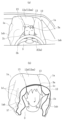
한편 이 종류의 에어백(1)은 도 9에 나타낸 바와 같이 차량용 시트(2)의 등받이부(2a)를 지지하는 프레임(2b)의 한쪽 측부로부터 상부를 경유하여 타방 측부에 걸쳐 예를 들어, 롤링 형상으로 감은 상태로 수납된다. 구체적으로는 상기 에어백(1)에 형성된 챔버(1a)를 구성하는 머리부 보호 챔버(1aa)는 상기 등받이부(2a)의 상부에 수납되고, 상기 챔버(1a)를 구성하는 측부 보호 챔버(1ab)는 상기 등받이부(2a)의 좌우 양측부의 서로 이간한 대향 위치에 수납된다. 또한 등받이부(2a)의 상부란 도 9의 (b)에 나타낸 바와 같은 헤드레스트(2c)를 일체적으로 형성하고 있는 차량용 시트(2)의 경우에는 헤드레스트(2c)의 상부를 의미한다. On the other hand, this type of
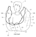
상기 에어백(1)은 예를 들어 도 10A에 나타낸 바와 같이 미팽창의 에어백(1)을 펼쳐 평탄면에 평평하게 놓은 상태에서는 상하 방향보다도 좌우 방향이 긴 형상이고, 동일한 형상의 2장의 기포(1b, 1c)를 서로 겹친 상태에서, 외주부와 좌우 방향의 중심을 봉제(4, 5)함으로써 봉제(5)의 좌우에 동일한 형상의 팽창 가능한 상기 챔버(1a)를 형성하고 있다.As shown in FIG. 10A, for example, the
상기 에어백(1)은 좌우의 상기 챔버(1a)의 각각의 외측 하부에 인플레이터(6)의 삽입부(1e)를 형성하고, 좌우의 상기 챔버(1a)에 각기 다른 인플레이터(6)로부터 가스를 공급하는 구성이고, 좌우의 상기 챔버(1a)는 유체적으로 독립하고 있다. In the
또한 좌우의 상기 챔버(1a)는 좌우 방향의 중간 부분에 적절한 개수의 비팽창부(1d)를 설치함으로써 에어백(1)의 좌우 각각의 양단 측에 위치하는 측부 보호 챔버(1ab)와 에어백(1)의 좌우 방향의 중앙부에 위치하는 머리부 보호 챔버(1aa)로 구획하고 있다.In addition, the left and
따라서 인플레이터(6)로부터 공급된 가스는 측부 보호 챔버(1ab)를 팽창시킴과 함께 상기 비팽창부(1d)들의 사이 및 상기 비팽창부(1d)와 외주부의 봉제(4)의 사이를 지나서 머리부 보호 챔버(1aa)에도 공급되며 머리부 보호 챔버(1aa)를 팽창시킨다. 또한 도 10A 중, (1f)는 상기 측부 보호 챔버(1ab)에 설치된 비팽창부를 나타낸다.Therefore, the gas supplied from the
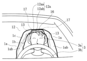
예를 들어 도 10A에 나타내는 에어백(1)을 롤링 형상으로 감은 상태로 도 9에 나타낸 바와 같이 수납한 경우, 상기 에어백(1)의 팽창 전개 완료 시에는 도 10B에 나타낸 바와 같은 상태로 챔버(1a)가 부풀게 된다. 이 때문에 승차인(3)이 정규 상태로 차량용 시트(2)에 착석하고 있지 않은 경우에는 팽창 전개의 초기 시에 승차인(3)의 머리부(3a)와 상기 머리부(3a)를 덮는 머리부 보호 챔버(1aa)가 강하게 간섭하고(도 10C의 (a)를 참조), 팽창 전개 완료 시에는 승차인(3)의 전방으로의 에어백(1)의 전개가 불충분해지고 승차인(3)을 적정하게 보호할 수 없다(도 10C의 (b)를 참조).For example, when the
본 발명이 해결하고자 하는 문제점은 예를 들어 승차인의 착석 위치가 좌우 방향으로 치우쳐 있는 경우, 에어백의 팽창 전개 시에 승차인과 챔버가 간섭하면 상기 간섭 정도에 따라서는 소기의 전개 성능을 얻을 수 없게 된다는 점이다.The problem to be solved by the present invention is, for example, when the seated position of the occupant is skewed in the left and right directions, when the occupant and the chamber interfere with the inflation and deployment of the airbag, desired deployment performance can be obtained depending on the degree of interference. that there will be no
본 발명은 상기 과제를 해결한다. 구체적으로는 승차인의 착석 위치가 좌우 방향으로 치우쳐 있는 경우 등과 같이, 정규 상태로 차량용 시트에 착석하고 있지 않은 경우에도 팽창 전개 시에 에어백이 승차인의, 특히 머리부와 강하게 간섭하지 않고 소기의 전개 성능을 얻을 수 있도록 하는 것을 목적으로 하고 있다.The present invention solves the above problems. Specifically, even when the occupant is not seated in the vehicle seat in a normal state, such as when the occupant's seating position is skewed in the left and right directions, the airbag does not strongly interfere with the occupant, especially the head, during inflation and deployment, and the desired effect is achieved. Its purpose is to achieve deployment performance.
즉, 본 발명은 차량용 시트에 착석한 승차인의 머리부와 측방부를 일체적으로 덮도록 팽창 전개하는 에어백과, 상기 에어백에 가스를 공급하는 인플레이터를 구비한 에어백 장치이다.That is, the present invention is an airbag device comprising an airbag that inflates and deploys so as to integrally cover the head and side portions of a passenger seated in a vehicle seat, and an inflator that supplies gas to the airbag.
상기 에어백은 상기 차량용 시트의 좌우 방향 중심 측에 위치하여 팽창 전개 완료 시에는 상기 승차인의 전방으로 전개하는 결합부에 의해 물리적으로 결합된 한 쌍의 챔버를 가지고 있다. 그리고 상기 한 쌍의 챔버는 팽창 전개 시, 각각 독립하여 상기 차량용 시트의 좌우 양측으로부터 전방을 향하여 팽창 전개하고, 적어도 승차인의 측방부를 덮는 측부 보호 챔버를 가지고 있다.The airbag has a pair of chambers physically coupled by a coupling portion positioned at the center of the vehicle seat in the left and right directions and deployed toward the front of the occupant upon completion of inflation and deployment. In addition, the pair of chambers independently expand and deploy toward the front from both left and right sides of the vehicle seat during inflation and deployment, and have side protection chambers covering at least a side portion of the occupant.
본 발명에서는, 상기 측부 보호 챔버는 상기 결합부에서 결합되고 적어도 팽창 전개 초기 시에는 상기 결합부가 상기 측부 보호 챔버보다도 얇은 두께가 되도록 구성되어 있는 것이 특징이다.In the present invention, it is characterized in that the side protection chamber is coupled at the coupling portion, and the coupling portion is configured to be thinner than the side protection chamber at least at the initial stage of expansion and deployment.
본 발명에 있어서 '팽창 전개 초기 시'란 에어백이 팽창 전개를 개시한 후 차량용 시트의 좌우 방향 중심 측에 위치하고 있고 팽창 전개 완료 시에는 승차인의 전방으로 전개하는 결합부가 승차인의 두정부의 상방을 통과할 때까지를 말한다.In the present invention, 'at the beginning of inflation and deployment' is located at the center side of the vehicle seat in the left and right directions after the airbag starts inflation and deployment, and when the inflation and deployment is completed, the coupling unit that deploys forward of the occupant is located above the occupant's head. until it passes through
상기 본 발명에서는, 측부 보호 챔버를 차량용 시트의 좌우 방향 중심 측에서 결합하는 결합부가, 적어도 팽창 전개 초기 시에 있어서는 상기 측부 보호 챔버보다도 얇은 두께가 되도록 구성하고 있다. 따라서, 예를 들어 승차인의 착석 위치가 좌우 방향으로 치우쳐 있는 경우여도, 에어백의 팽창 전개 초기 시에 상기 결합부가 승차인의 머리부와 강하게 간섭하는 것을 억제 가능하므로 소기의 전개 성능을 얻을 수 있다.In the present invention described above, the coupling portion that engages the side protection chamber at the center side in the left and right direction of the vehicle seat is configured to be thinner than the side protection chamber at least in the initial stage of inflation and deployment. Therefore, for example, even when the seated position of the occupant is skewed in the left-right direction, it is possible to suppress strong interference of the coupling part with the occupant's head at the initial stage of inflation and deployment of the airbag, so that desired deployment performance can be obtained. .
본 발명에 있어서 '결합부가 측부 보호 챔버보다도 얇은 두께가 되는' 구성에는 예를 들어 상기 결합부를 비팽창부로 하는 구성 외, 이너 벤트를 개재하여 측부 보호 챔버와 연결되는 딜레이(delay) 챔버부로 하는 구성도 있다. 또한 비팽창부와 상기 딜레이 챔버부를 함께 가지는 구성도 있다. 이러한 구성으로 한 경우에는 에어백의 팽창 전개 초기 시에 상기 결합부가 승차인의 특히 머리부와 강하게 간섭하지 않을 가능성이 커진다.In the present invention, in the configuration of 'the coupling part is thinner than the side protection chamber', for example, a configuration in which the coupling unit is a non-expandable unit, and a delay chamber unit connected to the side protection chamber through an inner vent There is also Also, there is a structure having both the non-expandable part and the delay chamber part. In the case of such a configuration, there is a high possibility that the coupling portion does not strongly interfere with the occupant's head, particularly at the initial stage of inflation and deployment of the airbag.
상기 결합부를 딜레이 챔버부로 한 경우, 측부 보호 챔버를 개재하여 딜레이 챔버부에 가스가 공급되므로 딜레이 챔버부의 팽창 전개는 측부 보호 챔버의 팽창 전개보다도 시간적으로 늦어지게 된다. 이 딜레이 챔버부의 상기 시간적인 지연 길이는 예를 들어 이너 벤트의 사이즈를 변경함으로써 제어할 수 있다.When the coupling part is the delay chamber part, gas is supplied to the delay chamber part through the side protection chamber, so that the expansion and development of the delay chamber part is delayed in time compared to the expansion and development of the side protection chamber. The temporal delay length of this delay chamber part can be controlled by changing the size of the inner vent, for example.
본 발명에 있어서 상기 딜레이 챔버부는 예를 들어 좌우 한 쌍의 팽창부를 포함하고 상기 측부 보호 챔버에 있어서의 상기 차량용 시트의 좌우 방향 중심 측에 설치된 상기 이너 벤트로부터 상기 팽창부에 가스가 공급되도록 해도 된다.In the present invention, the delay chamber part may include, for example, a pair of left and right expansion parts, and gas may be supplied to the expansion part from the inner vent provided in the left and right center of the vehicle seat in the side protection chamber. .
구체적으로는, 에어백은 적어도 2장의 기포로 구성되고 각각의 측부 보호 챔버와 딜레이 챔버부의 경계에는 외주 심(seam)과는 연결하지 않거나 혹은 외주 심과 연결하는 독립 심을 형성한다. 그리고 외주 심과는 연결하지 않은 독립 심의 경우에는 상기 독립 심과 외주 심 사이의 틈새가 이너 벤트가 된다. 한편 외주 심과 연결하는 독립 심의 경우에는 상기 독립 심에 이너 벤트를 이루는 틈새를 형성한다. 이러한 경우 상기 독립 심의 좌우 방향 중심 측에 외주 심과 연결하는 심을 더 형성함으로써 비팽창부를 형성한 것이어도 된다. Specifically, the airbag is composed of at least two sheets of foam, and an independent seam connected to or not connected to an outer seam is formed at a boundary between each side protection chamber and the delay chamber. In the case of an independent shim not connected to the outer shim, a gap between the independent shim and the outer shim becomes an inner vent. Meanwhile, in the case of an independent shim connected to the outer core, a gap forming an inner vent is formed in the independent shim. In this case, the non-expandable portion may be formed by further forming a core connected to the outer circumferential core on the left-right center side of the independent shim.
혹은 에어백은 측부 보호 챔버를 형성하는 2장의 기포와, 이들 2장의 기포 중 팽창 전개 시에 승차인 측 또는 승차인 반대 측이 되는 기포와 함께 딜레이 챔버부를 형성하는 추가 기포를 가지는 구성으로 한다. 그리고 이너 벤트는 팽창 전개 시에 승차인 측 또는 승차인 반대측이 되는 기포의 추가 기포로 덮는 부분에 설치한다. 이 경우 상기 측부 보호 챔버를 형성하는 2장의 상기 기포로 비팽창부를 형성하는 것이어도 된다.Alternatively, the airbag is configured to have two sheets of fabric that form a side protection chamber, and an additional fabric that forms a delay chamber portion together with a fabric that becomes the passenger's side or the passenger's side when inflating and deploying these two fabrics. In addition, the inner vent is installed in a portion covered with additional air bubbles on the passenger's side or the passenger's opposite side during expansion and deployment. In this case, the non-expandable portion may be formed with the two sheets of the air bubbles forming the side protection chamber.
본 발명에서는, 적어도 팽창 전개 초기 시는 승차인 측방부를 덮는 측부 보호 챔버를 결합하는 차량용 시트의 좌우 방향 중심 측에 위치하는 결합부가 측부 보호 챔버보다도 얇은 두께가 되도록 구성하고 있다. 따라서, 승차인의 착석 위치가 좌우 방향으로 치우쳐 있는 경우나 착석하고 있는 승차인의 상반신이 전방으로 기울어져 있는 경우에 있어서도, 팽창 전개 초기 시에 상기 결합부가 승차인과 강하게 간섭하는 것을 억제 가능하므로 소기의 전개 성능을 얻을 수 있고 승차인을 적정하게 보호 가능하다.In the present invention, at least in the initial stage of inflation and deployment, the coupling portion located at the center side in the left-right direction of the vehicle seat that engages the side protection chamber covering the passenger's side portion is configured to be thinner than the side protection chamber. Therefore, even when the seated position of the passenger is biased in the left-right direction or when the upper body of the seated passenger is tilted forward, it is possible to suppress strong interference of the engaging portion with the passenger at the initial stage of inflation and deployment. Desired deployment performance can be obtained, and the occupant can be adequately protected.
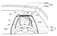
도 1A는 본 발명의 에어백 장치를 구성하는 에어백의 제1 실시예를 평탄면에 평평하게 놓아 펼친 전개 상태(접기 전 상태)를 나타낸 도이다.
도 1B는 도 1A에 나타낸 에어백의 팽창 전개 초기 시의 도로서, (a)는 차량의 전방으로부터 본 도, (b)는 승차인의 머리 상방에 위치하는 부분을 단면으로 나타낸 도이다.
도 1C는 도 1A에 나타낸 에어백의 팽창 전개 완료 시의 도로서, (a)는 차량의 전방으로부터 본 도, (b)는 승차인의 머리부를 보호하는 부분을 일부 생략하여 나타낸 도이다.
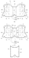
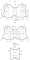
도 2A는 본 발명의 에어백 장치를 구성하는 에어백의 제2 실시예를 평탄면에 평평하게 놓아 펼친 전개 상태(접기 전 상태)를 나타낸 도이고, (a)는 독립 심과 외주 심 사이에 틈새를 형성한 도, (b)는 독립 심에 틈새를 형성한 도이다.
도 2B는 도 2A의 (b)에 나타낸 에어백의 팽창 전개 초기의 도로서, 차량의 전방으로부터 본 승차인의 머리부 상방에 위치하는 부분을 단면으로 나타낸다.
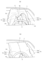
도 2C는 도 2A의 (b)에 나타낸 에어백의 팽창 전개 완료 시의 사시도로서, 승차인의 머리부를 보호하는 부분을 일부 생략하여 나타낸다.
도 3A는 본 발명의 에어백 장치를 구성하는 에어백의 제3 실시예의 기포를 평탄면에 평평하게 놓아 펼친 전개 상태(접기 전 상태)를 나타낸 도로서, (a)는 승차인 측의 기포, (b)는 승차인 반대측의 기포, (c)는 추가 기포를 나타내는 도이다.
도 3B는 도 3A에 나타낸 에어백의 팽창 전개 초기의 도로서, 차량의 전방으로부터 본 승차인의 머리부 상방에 위치하는 부분을 단면으로 나타낸다.
도 3C는 도 3A에 나타낸 에어백의 팽창 전개 완료 시의 사시도로서, 승차인의 머리부를 보호하는 부분을 일부 생략하여 나타낸다.
도 4A는 본 발명의 에어백 장치를 구성하는 에어백의 제4 실시예를 도 3A와 동일한 상태로 나타낸 도이다.
도 4B는 도 4A에 나타낸 제4 실시예를 도 3B와 동일한 상태로 나타낸 도이다.
도 4B는 도 4A에 나타낸 제4 실시예를 도 3C와 동일한 상태로 나타낸 도이다.
도 5는 본 발명의 에어백 장치를 구성하는 에어백의 제2 실시예의 변형예 1을 평탄면에 평평하게 놓아 펼친 전개 상태(접기 전 상태)를 나타낸 도이고, (a)는 독립 심과 외주 심 사이에 틈새를 형성한 도, (b)는 독립 심에 틈새를 형성한 도이다.
도 6은 본 발명의 에어백 장치를 구성하는 에어백의 제2 실시예의 변형예(2)를 도 5와 동일한 상태로 나타낸 도이다.
도 7은 본 발명의 에어백 장치를 구성하는 에어백의 제3 실시예의 변형예의 기포를 평탄면에 평평하게 놓아 펼친 전개 상태(접기 전 상태)를 나타낸 도로서, (a)는 승차인 측의 기포, (b)는 승차인 반대측의 기포, (c)는 추가 기포를 나타내는 도이다.
도 8은 본 발명의 에어백 장치를 구성하는 에어백의 제4 실시예의 변형예를 도 7과 동일한 상태로 나타낸 도이다.
도 9는 에어백을 설치한 차량용 시트를 차량의 후방으로부터 본 도이고, (a)는 헤드레스트가 차량용 시트의 등받이부에 별도로 설치되어 있는 것, (b)는 헤드레스트가 상기 등받이부와 일체로 형성되어 있는 것을 나타낸다.
도 10A는 본 발명의 에어백 장치를 구성하는 에어백의 제1 실시예의 베이스가 되는 에어백을 평탄면에 평평하게 놓아 펼친 전개 상태(접기 전 상태)를 나타낸 도이다.
도 10B는 도 10A에 나타낸 에어백의 팽창 전개 완료 시의 사시도이고, 승차인의 머리부를 보호하는 부분을 일부 생략하여 나타낸 것이다.
도 10C는 도 10A에 나타낸 에어백의 팽창 전개 상태를 차량의 전방으로부터 본 도이고, (a)는 팽창 전개 초기 시, (b)는 팽창 전개 완료 시를 나타낸 도이다.Fig. 1A is a diagram showing a deployed state (state before folding) in which a first embodiment of an airbag constituting the airbag device of the present invention is laid flat on a flat surface and unfolded.
Fig. 1B is a road at the beginning of inflation and deployment of the airbag shown in Fig. 1A, wherein (a) is a view from the front of the vehicle, and (b) is a cross-sectional view of a portion located above the head of a passenger.
Fig. 1C is a road after completion of inflation and deployment of the airbag shown in Fig. 1A, where (a) is a view as seen from the front of the vehicle, and (b) is a view showing a portion protecting the occupant's head with some omission.
2A is a diagram showing a deployed state (state before folding) in which the second embodiment of the airbag constituting the airbag device of the present invention is laid flat on a flat surface, and (a) shows a gap between the independent core and the outer core. Formed figure, (b) is a figure in which gaps are formed in independent shims.
Fig. 2B is a road at the initial stage of inflation and deployment of the airbag shown in Fig. 2A (b), showing in cross section a portion located above the occupant's head viewed from the front of the vehicle.
Fig. 2C is a perspective view of the airbag shown in Fig. 2A (b) when inflation and deployment is completed, and a portion protecting the occupant's head is partially omitted.
3A is a diagram showing a deployed state (state before folding) in which the airbag of the third embodiment of the airbag constituting the airbag device of the present invention is laid flat on a flat surface, (a) is the airbag on the passenger side, (b) ) is a bubble on the opposite side of the ride, and (c) is a diagram showing an additional bubble.
Fig. 3B is a road at the initial stage of inflation and deployment of the airbag shown in Fig. 3A, showing in cross section a portion located above the occupant's head as viewed from the front of the vehicle.
Fig. 3C is a perspective view of the airbag shown in Fig. 3A when inflation and deployment is completed, and a part protecting the occupant's head is omitted.
Fig. 4A is a diagram showing a fourth embodiment of an airbag constituting the airbag device of the present invention in the same state as Fig. 3A.
Fig. 4B is a diagram showing the fourth embodiment shown in Fig. 4A in the same state as Fig. 3B.
Fig. 4B is a diagram showing the fourth embodiment shown in Fig. 4A in the same state as Fig. 3C.
5 is a diagram showing a deployed state (state before folding) in which a modified example 1 of the second embodiment of the airbag constituting the airbag device of the present invention is laid flat on a flat surface, and (a) is a view showing a gap between an independent core and an outer core (b) is a diagram in which a gap is formed in an independent shim.
Fig. 6 is a view showing a modified example (2) of the second embodiment of the airbag constituting the airbag device of the present invention in the same state as Fig. 5;
7 is a diagram showing a deployed state (state before folding) in which the base fabric of a modified example of the third embodiment of the airbag constituting the airbag device of the present invention is laid flat on a flat surface, wherein (a) is the base fabric on the passenger side; (b) is a diagram showing air bubbles on the opposite side of the vehicle, and (c) is an additional air bubble.
Fig. 8 is a view showing a modified example of the fourth embodiment of the airbag constituting the airbag device of the present invention in the same state as Fig. 7;
9 is a view of a vehicle seat with an airbag installed as viewed from the rear of the vehicle, (a) a headrest is separately installed on the backrest of the vehicle seat, (b) the headrest is integrally with the backrest indicates what has been formed.
Fig. 10A is a diagram showing a deployed state (state before folding) in which the airbag serving as the base of the first embodiment of the airbag constituting the airbag apparatus of the present invention is laid flat on a flat surface and unfolded (state before folding).
Fig. 10B is a perspective view of the airbag shown in Fig. 10A when inflation and deployment is completed, and a portion protecting the occupant's head is partially omitted.
Fig. 10C is a view showing the inflation and deployment state of the airbag shown in Fig. 10A as viewed from the front of the vehicle, wherein (a) is a view showing an initial stage of inflation and deployment, and (b) a diagram showing a stage of completion of inflation and deployment.
예를 들어 승차인의 착석 위치가 좌우 방향으로 치우쳐 있는 경우, 에어백의 팽창 전개 초기 시에 승차인의, 특히 머리부와 챔버가 간섭하면 상기 간섭 정도에 따라서는 소기의 전개 성능을 얻을 수 없게 된다.For example, when the seated position of the occupant is skewed in the left and right directions, if the occupant's seat, particularly the head part and the chamber interfere with each other at the initial stage of inflation and deployment of the airbag, desired deployment performance cannot be obtained depending on the degree of interference. .
본 발명은, 적어도 팽창 전개 초기 시는 차량용 시트의 좌우 방향 중심 측에 위치하고, 팽창 전개 종료 시에 승차인의 전방으로 전개하는 결합부가 적어도 승차인의 측방부를 덮는 측부 보호 챔버보다도 얇은 두께가 되도록 구성함으로써 상기 과제를 해결하는 것이다. The present invention is configured so that the coupling part that is located at the center side of the vehicle seat in the left and right direction at least at the initial stage of inflation and deployment and deploys in front of the occupant at the end of inflation and deployment is thinner than the side protection chamber covering at least the lateral portion of the occupant. It is to solve the above problem by doing.
이하, 본 발명의 실시예를 도 1A~도 4C를 사용하여 설명한다.Hereinafter, an embodiment of the present invention will be described using Figs. 1A to 4C.
(제1 실시예: 도 1A~도 1C)(First Embodiment: FIGS. 1A to 1C)
본 발명의 에어백 장치(11)는 차량의 충돌 시에 차량용 시트(2)에 착석한 승차인(3)의 머리부(3a)와 예를 들어 승차인(3)의 어깨부, 상완부, 흉부의 측방부(3b)를 덮도록 팽창 전개하는 에어백(12)과, 차량에 대한 충격을 검출한 센서로부터의 신호에 의해 상기 에어백(12)의 내부에 가스를 분출하는 인플레이터(6)를 구비하고 있다.The
차량용 시트(2)는 시트 쿠션과 등받이부(2a)를 구비하고 있고 등받이부(2a)는 그 상부에 헤드레스트(2c)가 일체로 형성되거나 혹은 별도로 설치되어 있다. 상기 시트 쿠션 및 상기 등받이부(2a)는 프레임(2b)(도 9를 참조)에 의해 지지되어 있다. 에어백(12)은 도 1A에 나타내는 평평하게 놓은 상태에 있어서 전 측으로부터 후 측을 향하여 롤링 형상으로 감음으로써 전후 방향의 치수가 짧아지고 등받이부(2a)에 수납될 때의 수납 상태가 된다. 에어백(12)은 도 9에 나타낸 바와 같이 차량용 시트(2)의 등받이부(2a)를 지지하는 프레임(2b)의 한쪽 측부로부터 상부를 경유하여 타방 측부에 걸쳐 롤링 형상으로 감은 상태로 수납된다. The
에어백(12)은 상기 차량용 시트(2)의 좌우 방향 중심 측에 위치하여 팽창 전개 완료 시에는 승차인(3)의 전방으로 전개하는 결합부(12a)에 의해 결합된 한 쌍의 챔버(1a)를 가지고, 한 쌍의 챔버(1a)는 팽창 전개 시, 차량용 시트(2)의 좌우 양측으로부터 전방을 향하여 팽창 전개하고, 적어도 승차인(3)의 측방부를 덮는 한 쌍의 측부 보호 챔버(1ab)를 가지고 있다. 상기 에어백(12)은 예를 들어 도1A에 나타낸 바와 같이, 먼저 도 10A에서 설명한 에어백(1)의 측부 보호 챔버(1ab)와 머리부 보호 챔버(1aa)를 외주의 봉제(4)와 연결하는 예를 들어 봉제(13)에 의해 구획하고 좌우 방향 중심의 봉제(5)를 없앤 구성이다.The
즉, 도 1A에 나타낸 에어백(12)에서는 도 10A의 머리부 보호 챔버(1aa)에 상당하는 부분이 결합부(12a)가 되고 상기 결합부(12a)에 의해 좌우의 측부 보호 챔버(1ab)가 물리적으로 결합되게 된다. 이 경우, 상기 결합부(12a)는 가스가 공급되지 않는 비팽창부(12aa)가 되기 때문에 에어백(12)의 팽창 전개 완료 시에도 도 1C의 (b)에 나타낸 바와 같이 결합부(12a)는 팽창하지 않는다. 또한 챔버(1a), 측부 보호 챔버(1ab) 및 후술하는 딜레이 챔버부(12ab)에 대하여, '챔버'란 내부 공간 뿐만 아니라 그 내부 공간을 형성하는 기포를 포함하는 주머니체를 의미한다.That is, in the
따라서 에어백(12)이 팽창 전개를 개시하고 나서 결합부(12a)(비팽창부(12aa))가 승차인(3)의 머리부(3a)의 상방을 통과할 때까지의 팽창 전개 초기 시에는 상기 결합부(12a)(비팽창부(12aa))는 승차인(3)의 머리부(3a)와 간섭하지 않는다(도 1B를 참조). 결합부(12a) 전체가 비팽창부(12aa)로 구성되어 있고 측부 보호 챔버(1ab)보다도 두께가 얇기 때문이다. 그리고 에어백(12)의 팽창 전개가 완료했을 때에는 에어백(12)(결합부(12a))이 승차인(3)의 전방으로 확실하게 전개하여 머리부(3a)를 덮기 때문에 소기의 전개 성능을 얻을 수 있다(도 1C를 참조).Therefore, at the initial stage of inflation and deployment from the start of inflation and deployment of the
(제2 실시예: 도 2A~도 2C)(Second Embodiment: FIGS. 2A to 2C)
본 발명의 제2 실시예는 상기 제1 실시예를 구성하는 에어백(12)의 좌우 방향 중심에 상기 봉제(5)를 설치함과 함께 상기 봉제(13)의 예를 들어 상단부를 외주의 봉제(4)와 연결시키지 않고 틈새(14)를 설치한 것이다(도 2A의 (a)를 참조). 혹은 상기 제1 실시예를 구성하는 에어백(12)의 좌우 방향 중심에 상기 봉제(5)를 설치함과 함께 상기 봉제(13)의 예를 들어 상부 측에 틈새(15)를 형성한 것이다(도 2A의 (b)를 참조). In the second embodiment of the present invention, the
이러한 제2 실시예의 경우, 상기 결합부(12a)는 이너 벤트를 이루는 상기 틈새(14) 혹은 (15)를 개재하여 측부 보호 챔버(1ab)로부터 공기가 공급되는 딜레이 챔버부(12ab)가 된다. 봉제(4)는 '외주 심'의 일례이고, 도 2A의 (a)의 봉제(13)는 '외주 심과는 연결하지 않는 독립 심'의 일례이고, 도 2A의 (b)의 봉제(13)는 '외주 심과 연결하는 독립 심'의 일례이다.In the case of the second embodiment, the
따라서 결합부(12a)는 측부 보호 챔버(1ab)보다도 시간적으로 지연되어 팽창 전개가 완료함으로써 팽창 전개 초기 시는 측부 보호 챔버(1ab)보다도 얇은 두께이고(도 2B를 참조) 결합부(12a)와 승차인(3)의 머리부(3a)의 강한 간섭이 억제된다. 그리고 팽창 전개 완료 시에는 도 2C에 나타낸 바와 같이 에어백(12)(결합부(12a))이 승차인(3)의 전방으로 확실하게 전개하여 머리부(3a)를 포함하는 상체 부분을 덮는 형태가 된다.Therefore, the
측부 보호 챔버(1ab)보다도 늦게 팽창 전개가 완료한 딜레이 챔버부(12ab)는 승차인(3)의 머리부(3a) 및 흉부의 정면 측을 보호한다. 상기 결합부(12a)(딜레이 챔버부(12ab))의 팽창 전개의 상기 시간적인 지연 길이는 예를 들어 이너 벤트를 이루는 상기 틈새(14) 혹은 (15)의 사이즈를 변경함으로써 제어할 수 있다.The delay chamber portion 12ab, which is inflated and deployed later than the side protection chamber 1ab, protects the front side of the
(제3 및 제4 실시예: 도 3A~도 3C 및 도 4A~도 4C)(Third and fourth embodiments: FIGS. 3A to 3C and FIGS. 4A to 4C)
본 발명의 제3 실시예 및 제4 실시예는 에어백(12)을 구성하는 2장의 기포(1b, 1c)의 제1 실시예 또는 제2 실시예의 상기 결합부(12a)를 형성하는 부분에 추가 기포(16)를 예를 들어 상기 봉제(4) 및 (13)에 의해 설치한 것이다.The third and fourth embodiments of the present invention are added to the part forming the
그때 제3 실시예는 팽창 전개 시에 승차인 측이 되는 기포(1b)의 외측(승차인 측)에 상기 추가 기포(16)를 설치한다. 또한 제4 실시예는 팽창 전개 시에 승차인 반대측이 되는 기포(1c)의 외측(승차인 반대측)에 상기 추가 기포(16)를 설치한다.At that time, in the third embodiment, the
그리고 제3 실시예에 있어서는 상기 기포(1b)는 도 3A의 (a)에 나타내는 상기 봉제(13)의 좌우 방향 중심 측에서도 도 3A의 (b)에 나타낸 바와 같이 상기 기포(1c)와 봉제(17)하고, 이들 봉제(17)와 연결하는 외주의 봉제(4)로 구획되는 두 기포(1b, 1c) 사이의 좌우 방향 중심부를 팽창하지 않는 비팽창부(12aa)로 하고 있다. 또한 제4 실시예에 있어서는 상기 기포(1c)는 도 4A의 (b)에 나타내는 상기 봉제(13)의 좌우 방향 중심 측에서도 도 4A의 (a)에 나타낸 바와 같이 상기 기포(1b)와 봉제(17)하고, 이들 봉제(17)와 연결하는 외주의 봉제(4)로 구획되는 두 기포(1b, 1c) 사이의 좌우 방향 중심부를 팽창하지 않는 비팽창부(12aa)로 하고 있다.And in the third embodiment, the
아울러 제3 실시예에서는 팽창 전개 시에 승차인 측이 되는 상기 기포(1b)의 상기 비팽창부(12aa)의 좌우 방향 두 외측의 부분에 한 쌍의 이너 벤트(12b)를 설치하고 있다. 또한 제4 실시예에서는 팽창 전개 시에 승차인 반대측이 되는 상기 기포(1c)의 상기 비팽창부(12aa)의 좌우 방향 두 외측의 부분에 한 쌍의 이너 벤트(12b)를 설치하고 있다. 도 3A의 (a) 및 도 4A의 (b)에 나타낸 바와 같이 이너 벤트(12b)는 기포(1b, 1c)의 추가 기포(16)로 덮는 부분에 설치한다.In addition, in the third embodiment, a pair of
즉 제3 실시예 및 제4 실시예는 팽창 전개 시에 승차인 측이 되는 기포(1b)와 팽창 전개 시에 승차인 반대측이 되는 기포(1c)와 추가 기포(16)로 결합부(12a)를 형성한 것이다.That is, in the third and fourth embodiments, the
그리고 이들 결합부(12a)는 두 기포(1b, 1c)의 좌우 방향 중심부에 위치하는 비팽창부(12aa)와 상기 한쪽의 기포(1b) 또는 (1c)와 추가 기포(16)로 형성하는 딜레이 챔버부(12ab)로 구성되어 있다.In addition, these
이들 제3 실시예 및 제4 실시예의 경우, 에어백(12)의 팽창 전개 시에는 이너 벤트(12b)를 개재하여 측부 보호 챔버(1ab)로부터 딜레이 챔버부(12ab)에만 공기가 공급된다.In the case of these third and fourth embodiments, when the
따라서 딜레이 챔버부(12ab)는 측부 보호 챔버(1ab)보다도 시간적으로 지연되어 팽창 전개하고, 팽창 전개 초기 시는 측부 보호 챔버(1ab)보다도 얇은 두께이고(도 3B, 도 4B를 참조) 결합부(12a)와 승차인(3)의 머리부(3a)의 강한 간섭이 억제된다. 그리고 팽창 전개 완료 시에는 도 3C, 도 4C에 나타낸 바와 같이 에어백(12)(결합부(12a))이 승차인(3)의 전방으로 확실하게 전개하여 머리부(3a)를 포함하는 상체 부분을 덮는 형태가 된다. 또한 비팽창부(12aa)에는 공기는 공급되지 않지만 봉제(4)와 봉제(13)로 형성된 기포(1b) 또는 (1c)와 추가 기포(16) 사이에는 공기가 공급되므로 이들 제3 실시예 및 제4 실시예의 결합부(12a)는 실질적으로 딜레이 챔버(12ab)를 구성하고 있고 팽창 전개 완료 시에 승차인(3)의 머리부(3a) 및 흉부의 정면 측을 보호한다(도 3B, 도 3C 및 도 4B, 도 4C를 참조).Therefore, the delay chamber portion 12ab expands and deploys with a delay in time compared to the side protection chamber 1ab, and has a thickness smaller than that of the side protection chamber 1ab at the initial stage of expansion and development (see FIGS. 3B and 4B), and the coupling portion ( Strong interference between 12a) and the
본 발명은 상기의 예에 한정되지 않으며 각 청구항에 기재된 기술적 사상의 범주라면 적절하게 실시형태를 변경해도 되는 것은 말할 것도 없다.It goes without saying that the present invention is not limited to the above examples, and the embodiments may be appropriately changed as long as they are within the scope of the technical idea described in each claim.
즉 이상에서 서술한 에어백 장치는 본 발명의 적합한 예이며, 이 이외의 실시형태도 각종 방법으로 실시 또는 수행 가능하다. 특히 본원 명세서 중에 한정된다는 주지의 기재가 없는 한 본 발명은 첨부 도면에 나타낸 부품의 형상, 크기 및 구성 배치 등으로 제약되는 것은 아니다. 또한 본원 명세서 중에 사용된 표현 및 용어는 설명을 목적으로 한 것이며 특별히 한정된다는 주지가 없는 한 그것으로 한정되는 것은 아니다.That is, the above-described airbag device is a suitable example of the present invention, and other embodiments can be implemented or carried out by various methods. In particular, the present invention is not limited to the shape, size, configuration arrangement, etc. of the parts shown in the accompanying drawings unless there is a well-known description that it is limited in the specification. In addition, expressions and terms used in the specification of the present application are for the purpose of explanation and are not limited thereto unless it is noted that they are particularly limited.
예를 들어 도 2A의 (a)의 제2 실시예에서는 측부 보호 챔버(1ab)와 결합부(12a)를 구획하는 봉제(13)의 상단부를 외주의 봉제(4)와 연결시키지 않는 것을 나타냈으나, 봉제(13)의 하단부를 외주의 봉제(4)와 연결시키지 않아도 된다. 또한 봉제(13)의 상단부 및 하단부를 외주의 봉제(4)와 연결시키지 않아도 된다.For example, in the second embodiment of FIG. 2A (a), it has been shown that the upper end of the
또한 도 2A의 (b)에 나타낸 제2 실시예에서는 측부 보호 챔버(1ab)와 결합부(12a)를 구획하는 봉제(13)의 상부 측에 하나의 틈새(15)를 설치한 것을 나타냈으나 상기 틈새(15)는 1개로 한정되지 않으며 또한 설치 위치도 상부 측으로 한정되지 않고, 중앙부나 하부 측이어도 된다. In addition, in the second embodiment shown in (b) of Figure 2A, it was shown that one
또한 도 2A (ab)에 나타낸 제2 실시예에서는 좌우 방향 중심에 봉제(5)를 설치한 것을 나타내고 있으나 도 5의 (a)(b)에 나타낸 바와 같이 좌우 방향 중심의 봉제(5)를 없애고 좌우 방향의 중심부에 1개의 딜레이 챔버부(12ab)를 형성한 것이어도 된다. 또한 도 6의 (a)(b)에 나타낸 바와 같이 좌우 방향 중심의 봉제(5)를 없애고 좌우 방향 중심부에 적절한 틈새를 두고 2개의 봉제(18)를 설치하고 이들 봉제(18) 사이를 비팽창부(12aa)로 하여도 된다. 도 6의 (a)(b)에 나타낸 변형예에 있어서의 봉제(18)는 '외주 심과 연결하는 심'의 일례이다.In addition, in the second embodiment shown in Figure 2A (ab), it shows that the
또한 도 3A에 나타낸 제3 실시예 및 도 4A에 나타낸 제4 실시예에서는 결합부(12a)에 두 기포(1b, 1c)로 형성한 비팽창부(12aa)와, 어느 한쪽의 기포(1b) 또는 (1c)와 추가 기포(16)로 형성한 딜레이 챔버부(12ab)를 가지고 있다.In addition, in the third embodiment shown in FIG. 3A and the fourth embodiment shown in FIG. 4A, a non-expandable portion 12aa formed of two
그러나 기포(1b)와 기포(1c)에 더하여 추가 기포(16)도 함께 봉제(17)하여 비팽창부(12aa)를 형성해도 된다(도 7 및 도 8을 참조).However, in addition to the
또한 본 발명의 에어백 장치(11)는 에어백(12)을 롤링 형상으로 감은 상태로 차량용 시트(2)의 등받이부(2a)에 수납하는 것으로 한정하지 않고 벨로스(Bellows)형상으로 접은 상태로 상기 등받이부(2a)에 수납하는 것이어도 된다.In addition, the
또한 본 발명의 에어백 장치(11)는 에어백(12)을 차량용 시트(2)의 등받이부(2a)에 수납할 시, 도 9에 나타낸 바와 같은 측부 보호 챔버(1ab)를 프레임(2b)의 좌우 방향 외측에 설치하는 것으로 한정하지 않고 프레임(2b)의 좌우 방향 내측에 설치해도 된다. 또한 인플레이터(6)도 프레임(2b)의 좌우 방향 내측 또는 외측의 어느 쪽에 설치해도 된다.In addition, in the
또한 상기 제1 실시예~제4 실시예에서는 승차인(3)의 머리부(3a)와, 승차인(3)의 어깨부, 상완부, 흉부의 측방부(3b)를 보호하는 에어백 장치(11)에 대하여 설명하고 있다. 그러나 승차인(3)의 머리부(3a)와, 승차인(3)의 어깨부, 상완부, 흉부에 더하여 승차인(3)의 복부와 허리부의 측방부까지를 보호하는 에어백 장치에 본 발명을 적용해도 된다.In addition, in the first to fourth embodiments, the
또한 상기 제1 실시예~제4 실시예에서는 좌우에 설치한 인플레이터(6)로 좌우의 챔버(1a)를 팽창 전개시키고 있으나 좌우의 챔버(1a)가 독립하여 팽창 전개하는 것이라면 1개의 인플레이터(6)로 좌우의 챔버(1a)에 가스를 공급하는 것이어도 된다.In the first to fourth embodiments, the left and
또한 상기 제1 실시예~제4 실시예에서 설명한 에어백(12)은 2장의 기포(1b, 1c), 또는 2장의 기포(1b, 1c)와 추가 기포(16)를 봉제하여 형성하고 있다. 그러나 2장의 기포(1b, 1c), 또는 2장의 기포(1b, 1c)와 추가 기포(16)를 강고하게 접합 가능한 것이라면 접착이나 용착 등이어도 된다. 또한 이른바 '원피스 웨빙(one-piece weaving)' 기술을 사용하여 형성한 것이어도 된다.In addition, the
상술한 실시예에서는 착석한 승차인이 차량 전방을 향하는 차량용 시트(2)에 에어백 장치(11)를 설치하고 있으나 착석한 승차인이 차량 후방을 향하는 것도 가능한 차량용 시트(2)에 에어백 장치(11)를 설치해도 된다. 이와 같은 차량용 시트(2)는 자동 운전의 차량 등에 설치할 수 있다.In the above-described embodiment, the
1a 챔버
1ab 측부 보호 챔버
1b, 1c 기포
2 차량용 시트
3 승차인
3a 머리부
3b 측방부
4 봉제
6 인플레이터
11 에어백 장치
12 에어백
12a 결합부
12aa 비팽창부
12ab 딜레이 챔버부
12b 이너 벤트
13 봉제
14 틈새
15 틈새
16 추가 기포
17 봉제
18 봉제1a chamber
1ab side protection chamber
1b, 1c bubbles
2 car seats
3 riders
3a head
3b lateral part
4 plush
6 inflator
11 airbag device
12 airbags
12a joint
12aa non-expandable part
12ab delay chamber
12b inner vent
13 plush
14 niche
15 niche
16 additional bubbles
17 plush
18 plush
Claims (11)
상기 에어백은 상기 차량용 시트의 좌우 방향 중심 측에 위치하여 팽창 전개 완료 시에는 상기 승차인의 전방으로 전개하는 결합부에 의해 결합된 한 쌍의 챔버를 가지고,
상기 한 쌍의 챔버는 팽창 전개 시, 상기 차량용 시트의 좌우 양측으로부터 각각 전방을 향하여 팽창 전개하고, 적어도 승차인의 측방부를 덮는 한 쌍의 측부 보호 챔버를 가지고,
상기 측부 보호 챔버는 상기 결합부에서 결합되고, 적어도 팽창 전개 초기 시에는, 상기 결합부가 상기 측부 보호 챔버보다도 얇은 두께가 되도록 구성되어 있는 에어백 장치.An airbag device comprising an airbag that inflates and deploys to integrally cover the head and side portions of a passenger seated in a vehicle seat, and an inflator that supplies gas to the airbag, comprising:
The airbag has a pair of chambers coupled by a coupling portion located at the center side of the vehicle seat in the left and right directions and deployed forward of the occupant when inflation and deployment are completed,
The pair of chambers inflate and deploy toward the front from both left and right sides of the vehicle seat when inflating and deploying, and have a pair of side protection chambers covering at least the side portions of the occupant,
The airbag device of claim 1 , wherein the side protection chamber is coupled at the coupling portion, and the coupling portion is configured to be thinner than the side protection chamber at least at an initial stage of inflation and deployment.
상기 결합부는 비팽창부로 구성되는 에어백 장치.According to claim 1,
The airbag device of claim 1, wherein the coupling portion is constituted by a non-inflatable portion.
상기 결합부는, 상기 측부 보호 챔버와 연결되는 이너 벤트를 개재하여 공급되는 가스에 의해, 상기 측부 보호 챔버보다도 시간적으로 지연되어 팽창 전개가 완료하는 딜레이 챔버부를 가지는 에어백 장치.According to claim 1,
The airbag device of claim 1 , wherein the coupling portion has a delay chamber portion in which inflation and deployment is completed with a time delay from the side protection chamber by a gas supplied through an inner vent connected to the side protection chamber.
상기 결합부는 비팽창부와, 상기 측부 보호 챔버와 연결되는 이너 벤트를 개재하여 공급되는 가스에 의해, 상기 측부 보호 챔버보다도 시간적으로 지연되어 팽창 전개가 완료하는 딜레이 챔버부를 함께 가지는 에어백 장치.According to claim 1,
The airbag device of claim 1 , wherein the engaging portion includes a non-inflating portion and a delay chamber portion in which inflation and deployment are completed by delaying time from the side protection chamber by a gas supplied through an inner vent connected to the side protection chamber.
상기 딜레이 챔버부는 좌우 한 쌍의 팽창부를 포함하고, 상기 측부 보호 챔버에 있어서의 상기 차량용 시트의 좌우 방향 중심 측에 설치된 상기 이너 벤트로부터 상기 팽창부에 상기 가스가 공급되는 에어백 장치.According to claim 3 or 4,
The airbag device of claim 1 , wherein the delay chamber part includes a pair of left and right expansion parts, and the gas is supplied to the expansion part from the inner vent installed at a center side of the vehicle seat in the left and right directions in the side protection chamber.
상기 에어백은 적어도 2장의 기포로 구성되고, 상기 각각의 측부 보호 챔버와 상기 딜레이 챔버부의 경계에는, 외주 심과는 연결하지 않는 독립 심이 형성되고, 이들 독립 심과 상기 외주 심 사이의 틈새가 이너 벤트를 이루는 에어백 장치.According to claim 3 or 5,
The airbag is composed of at least two air bubbles, and independent seams not connected to the outer circumferential core are formed at the boundary between each of the side protection chambers and the delay chamber, and the gap between these independent shims and the outer circumferential core is an inner vent. Airbag device constituting the.
상기 에어백은 적어도 2장의 기포로 구성되고, 상기 각각의 측부 보호 챔버와 상기 딜레이 챔버부의 경계에 형성된, 외주 심과는 연결하지 않는 독립 심과 상기 외주 심 사이의 틈새를 이너 벤트로 하는 한편,
상기 독립 심의 좌우 방향 중심 측에, 외주 심과 연결하는 심을 형성함으로써 비팽창부가 형성되어 있는 에어백 장치.According to claim 4,
The airbag is composed of at least two air bubbles, and the gap between the outer core and the independent core formed at the boundary between each of the side protection chambers and the delay chamber portion, which is not connected to the outer core, is used as an inner vent,
An airbag device in which a non-inflatable portion is formed by forming a shim connected to an outer circumferential shim on the left-right center side of the independent shim.
상기 에어백은 적어도 2장의 기포로 구성되고, 상기 각각의 측부 보호 챔버와 상기 딜레이 챔버부의 경계에는, 외주 심과 연결하는 독립 심이 형성되고, 상기 독립 심에 이너 벤트를 이루는 틈새를 형성한 에어백 장치.According to claim 3 or 5,
The airbag device of
상기 에어백은 적어도 2장의 기포로 구성되고, 상기 각각의 측부 보호 챔버와 상기 딜레이 챔버부의 경계에 형성된, 외주 심과 연결하는 독립 심에 이너 벤트를 이루는 틈새를 형성하는 한편,
상기 독립 심의 좌우 방향 중심 측에, 외주 심과 연결하는 심을 형성함으로써 비팽창부가 형성되어 있는 에어백 장치.According to claim 4,
The airbag is composed of at least two sheets of air bubbles, and a gap forming an inner vent is formed in an independent seam connected to an outer seam formed at a boundary between each of the side protection chambers and the delay chamber part,
An airbag device in which a non-inflatable portion is formed by forming a shim connected to an outer circumferential shim on the left-right center side of the independent shim.
상기 에어백은 상기 측부 보호 챔버를 형성하는 2장의 기포와, 이들 2장의 기포 중 팽창 전개 시에 승차인 측 또는 승차인 반대측이 되는 한쪽의 기포와 함께 상기 딜레이 챔버부를 형성하는 추가 기포를 가지고,
상기 이너 벤트는 상기 한쪽 기포의, 상기 추가 기포로 덮는 부분에 설치되어 있는 에어백 장치.According to claim 3 or 5,
The airbag has two sheets of airbags forming the side protection chamber and an additional airbag forming the delay chamber part together with one of the airbags that is the passenger side or the opposite side when inflating and deploying these two airbags,
The airbag device of claim 1 , wherein the inner vent is installed in a portion of the one air fabric covered with the additional air fabric.
상기 에어백은 상기 측부 보호 챔버를 형성하는 2장의 기포와, 이들 2장의 기포 중 팽창 전개 시에 승차인 측 또는 승차인 반대측이 되는 한쪽의 기포와 함께 상기 딜레이 챔버부를 형성하는 추가 기포를 가지고,
상기 이너 벤트는 상기 한쪽 기포의, 상기 추가 기포로 덮는 부분에 설치되고,
상기 비팽창부는 상기 측부 보호 챔버를 형성하는 2장의 상기 기포로 형성되어 있거나 혹은 2장의 상기 기포 및 상기 추가 기포로 형성되어 있는 에어백 장치.According to claim 4,
The airbag has two sheets of airbags forming the side protection chamber and an additional airbag forming the delay chamber part together with one of the airbags that is the passenger side or the opposite side when inflating and deploying these two airbags,
The inner vent is installed in a portion of the one bubble covered by the additional bubble,
The airbag device of claim 1 , wherein the non-inflatable portion is formed of two sheets of the air fabric forming the side protection chamber, or is formed of two sheets of the air fabric and the additional air bubble.
Applications Claiming Priority (3)
| Application Number | Priority Date | Filing Date | Title |
|---|---|---|---|
| JP2020116911 | 2020-07-07 | ||
| JPJP-P-2020-116911 | 2020-07-07 | ||
| PCT/JP2021/022671 WO2022009622A1 (en) | 2020-07-07 | 2021-06-15 | Airbag device |
Publications (1)
| Publication Number | Publication Date |
|---|---|
| KR20230031959A true KR20230031959A (en) | 2023-03-07 |
Family
ID=79552947
Family Applications (1)
| Application Number | Title | Priority Date | Filing Date |
|---|---|---|---|
| KR1020237004041A KR20230031959A (en) | 2020-07-07 | 2021-06-15 | air bag device |
Country Status (6)
| Country | Link |
|---|---|
| US (1) | US20230294629A1 (en) |
| EP (1) | EP4180278A1 (en) |
| JP (1) | JPWO2022009622A1 (en) |
| KR (1) | KR20230031959A (en) |
| CN (1) | CN115768663A (en) |
| WO (1) | WO2022009622A1 (en) |
Citations (2)
| Publication number | Priority date | Publication date | Assignee | Title |
|---|---|---|---|---|
| JP2018083554A (en) | 2016-11-24 | 2018-05-31 | 豊田合成株式会社 | Occupant protection device |
| JP2019014477A (en) | 2018-10-31 | 2019-01-31 | 豊田合成株式会社 | Occupant protection device |
Family Cites Families (19)
| Publication number | Priority date | Publication date | Assignee | Title |
|---|---|---|---|---|
| IT981219B (en) * | 1973-03-08 | 1974-10-10 | Alfa Romeo Spa | HEAD PROTECTION DEVICE FOR PASSENGERS OF MOTOR VEHICLES COLI IN THE EVENT OF AN IMPACT |
| JP2007230396A (en) * | 2006-03-01 | 2007-09-13 | Takata Corp | Airbag and airbag device |
| DE102009040641A1 (en) * | 2008-09-15 | 2010-04-15 | Takata-Petri Ag | Airbag device for vehicle seat of vehicle, has airbag and gas generator for inflating airbag, where airbag device is arranged in or on headrest of vehicle seat |
| US20130015642A1 (en) * | 2011-07-12 | 2013-01-17 | Zodiac Aerospace | Bonnet airbag |
| US9573553B2 (en) * | 2014-10-30 | 2017-02-21 | Hyundai Mobis Co., Ltd. | Airbag apparatus |
| BR112017021358B1 (en) * | 2015-04-28 | 2022-05-24 | Toyota Jidosha Kabushiki Kaisha | Occupant protection device |
| JP6411965B2 (en) * | 2015-07-28 | 2018-10-24 | トヨタ自動車株式会社 | Crew protection device |
| JP6500826B2 (en) * | 2016-04-08 | 2019-04-17 | トヨタ自動車株式会社 | Occupant protection device |
| EP3536563B1 (en) * | 2018-03-06 | 2021-04-28 | Autoliv Development AB | A vehicle seat |
| EP3581441B1 (en) * | 2018-06-13 | 2021-05-12 | Autoliv Development AB | A vehicle seat |
| KR102602954B1 (en) * | 2018-10-02 | 2023-11-16 | 현대자동차주식회사 | Airbag device of vehicle |
| WO2020080747A1 (en) * | 2018-10-19 | 2020-04-23 | 아우토리브 디벨롭먼트 아베 | Vehicular airbag device |
| US10899307B2 (en) * | 2018-11-19 | 2021-01-26 | GM Global Technology Operations LLC | Deployable headrest airbag |
| US10953836B2 (en) * | 2019-07-11 | 2021-03-23 | Autoliv Asp, Inc. | Surrounding airbag assemblies and methods of deployment |
| WO2021029197A1 (en) * | 2019-08-09 | 2021-02-18 | オートリブ ディベロップメント エービー | Airbag device, vehicle seat, and ignition method for airbag device |
| KR102403511B1 (en) * | 2019-08-09 | 2022-05-31 | 아우토리브 디벨롭먼트 아베 | Airbag apparatus |
| EP3792119B1 (en) * | 2019-09-16 | 2022-09-14 | Autoliv Development AB | Vehicle airbag system |
| KR20220075368A (en) * | 2019-10-11 | 2022-06-08 | 아우토리브 디벨롭먼트 아베 | Airbag device and vehicle seat |
| US20230202419A1 (en) * | 2020-05-28 | 2023-06-29 | Yoshiki Ito | Airbag device |
-
2021
- 2021-06-15 JP JP2022534982A patent/JPWO2022009622A1/ja active Pending
- 2021-06-15 CN CN202180043996.2A patent/CN115768663A/en active Pending
- 2021-06-15 US US18/004,012 patent/US20230294629A1/en active Pending
- 2021-06-15 KR KR1020237004041A patent/KR20230031959A/en unknown
- 2021-06-15 EP EP21838756.1A patent/EP4180278A1/en active Pending
- 2021-06-15 WO PCT/JP2021/022671 patent/WO2022009622A1/en unknown
Patent Citations (2)
| Publication number | Priority date | Publication date | Assignee | Title |
|---|---|---|---|---|
| JP2018083554A (en) | 2016-11-24 | 2018-05-31 | 豊田合成株式会社 | Occupant protection device |
| JP2019014477A (en) | 2018-10-31 | 2019-01-31 | 豊田合成株式会社 | Occupant protection device |
Also Published As
| Publication number | Publication date |
|---|---|
| US20230294629A1 (en) | 2023-09-21 |
| JPWO2022009622A1 (en) | 2022-01-13 |
| WO2022009622A1 (en) | 2022-01-13 |
| CN115768663A (en) | 2023-03-07 |
| EP4180278A1 (en) | 2023-05-17 |
Similar Documents
| Publication | Publication Date | Title |
|---|---|---|
| JP5949791B2 (en) | Vehicle occupant protection device | |
| KR101691959B1 (en) | Far side airbag device | |
| US20170028960A1 (en) | Passenger protecting device for vehicle | |
| US11752965B2 (en) | Side airbag device and method for manufacturing side airbag device | |
| JP7073534B2 (en) | A method for manufacturing a side airbag device, a vehicle seat equipped with the side airbag device, and a side airbag device. | |
| JP2008201175A (en) | Side airbag device | |
| JP6940627B2 (en) | Crew protection device | |
| US11254276B2 (en) | Side airbag apparatus and vehicle seat including the same | |
| JP5229238B2 (en) | Airbag device | |
| JP7270826B2 (en) | Airbag device and vehicle seat | |
| JP7078742B2 (en) | Vehicle seat | |
| KR20220075368A (en) | Airbag device and vehicle seat | |
| CN109955822B (en) | Side airbag device for vehicle | |
| JP6790024B2 (en) | Side airbag device and vehicle seat equipped with it | |
| JP7427780B2 (en) | air bag device | |
| JP7341321B2 (en) | Occupant protection device | |
| KR20230031959A (en) | air bag device | |
| JP2022154365A (en) | Far-side air bag device | |
| JPH10175497A (en) | Side air bag device | |
| JP6865723B2 (en) | Vehicle seat | |
| JP7217343B2 (en) | passenger protection device | |
| JP2023046992A (en) | Airbag device and passenger movable body including the same | |
| JP2023119079A (en) | Seat built-in air bag device |