KR20230014733A - Secondary battery and its manufacturing method - Google Patents
Secondary battery and its manufacturing method Download PDFInfo
- Publication number
- KR20230014733A KR20230014733A KR1020227044817A KR20227044817A KR20230014733A KR 20230014733 A KR20230014733 A KR 20230014733A KR 1020227044817 A KR1020227044817 A KR 1020227044817A KR 20227044817 A KR20227044817 A KR 20227044817A KR 20230014733 A KR20230014733 A KR 20230014733A
- Authority
- KR
- South Korea
- Prior art keywords
- negative electrode
- secondary battery
- sheet
- bending
- separator
- Prior art date
Links
- 238000004519 manufacturing process Methods 0.000 title claims description 39
- 238000005452 bending Methods 0.000 claims abstract description 57
- 239000007784 solid electrolyte Substances 0.000 claims abstract description 56
- 239000007773 negative electrode material Substances 0.000 claims abstract description 43
- 230000001154 acute effect Effects 0.000 claims abstract description 18
- 229910052744 lithium Inorganic materials 0.000 claims description 50
- 238000000034 method Methods 0.000 claims description 46
- 229910052751 metal Inorganic materials 0.000 claims description 45
- 239000002184 metal Substances 0.000 claims description 45
- WHXSMMKQMYFTQS-UHFFFAOYSA-N Lithium Chemical group [Li] WHXSMMKQMYFTQS-UHFFFAOYSA-N 0.000 claims description 25
- 239000000758 substrate Substances 0.000 claims description 18
- 238000000465 moulding Methods 0.000 claims description 17
- 239000007774 positive electrode material Substances 0.000 claims description 11
- 239000000956 alloy Substances 0.000 claims description 10
- 229910045601 alloy Inorganic materials 0.000 claims description 10
- 239000011888 foil Substances 0.000 claims description 10
- 229910052759 nickel Inorganic materials 0.000 claims description 8
- 229910052802 copper Inorganic materials 0.000 claims description 7
- 150000002739 metals Chemical class 0.000 claims description 5
- 238000003825 pressing Methods 0.000 claims description 4
- 239000010935 stainless steel Substances 0.000 claims description 4
- 229910001220 stainless steel Inorganic materials 0.000 claims description 4
- 229910052742 iron Inorganic materials 0.000 claims description 3
- 229910052719 titanium Inorganic materials 0.000 claims description 3
- 239000010410 layer Substances 0.000 description 25
- 239000011347 resin Substances 0.000 description 16
- 229920005989 resin Polymers 0.000 description 16
- 238000003475 lamination Methods 0.000 description 14
- 230000037303 wrinkles Effects 0.000 description 13
- 239000002033 PVDF binder Substances 0.000 description 12
- 229910003002 lithium salt Inorganic materials 0.000 description 12
- 159000000002 lithium salts Chemical class 0.000 description 12
- 239000000463 material Substances 0.000 description 12
- 229920002981 polyvinylidene fluoride Polymers 0.000 description 12
- OKTJSMMVPCPJKN-UHFFFAOYSA-N Carbon Chemical compound [C] OKTJSMMVPCPJKN-UHFFFAOYSA-N 0.000 description 11
- 239000003792 electrolyte Substances 0.000 description 11
- -1 polyethylene Polymers 0.000 description 11
- 238000007599 discharging Methods 0.000 description 9
- PXHVJJICTQNCMI-UHFFFAOYSA-N nickel Substances [Ni] PXHVJJICTQNCMI-UHFFFAOYSA-N 0.000 description 9
- HBBGRARXTFLTSG-UHFFFAOYSA-N Lithium ion Chemical compound [Li+] HBBGRARXTFLTSG-UHFFFAOYSA-N 0.000 description 8
- 150000001875 compounds Chemical class 0.000 description 8
- 239000010949 copper Substances 0.000 description 8
- 229910001416 lithium ion Inorganic materials 0.000 description 8
- 150000003839 salts Chemical group 0.000 description 8
- 239000002904 solvent Substances 0.000 description 8
- 239000012790 adhesive layer Substances 0.000 description 7
- 239000011230 binding agent Substances 0.000 description 7
- 230000000052 comparative effect Effects 0.000 description 7
- 238000000151 deposition Methods 0.000 description 7
- 238000002360 preparation method Methods 0.000 description 7
- WEVYAHXRMPXWCK-UHFFFAOYSA-N Acetonitrile Chemical compound CC#N WEVYAHXRMPXWCK-UHFFFAOYSA-N 0.000 description 6
- 239000008151 electrolyte solution Substances 0.000 description 6
- 229910021645 metal ion Inorganic materials 0.000 description 6
- 239000011247 coating layer Substances 0.000 description 5
- 230000014759 maintenance of location Effects 0.000 description 5
- 239000000203 mixture Substances 0.000 description 5
- 238000007789 sealing Methods 0.000 description 5
- LFQSCWFLJHTTHZ-UHFFFAOYSA-N Ethanol Chemical compound CCO LFQSCWFLJHTTHZ-UHFFFAOYSA-N 0.000 description 4
- 239000004698 Polyethylene Substances 0.000 description 4
- 229910021393 carbon nanotube Inorganic materials 0.000 description 4
- 239000002041 carbon nanotube Substances 0.000 description 4
- 238000003780 insertion Methods 0.000 description 4
- 230000037431 insertion Effects 0.000 description 4
- AMXOYNBUYSYVKV-UHFFFAOYSA-M lithium bromide Chemical compound [Li+].[Br-] AMXOYNBUYSYVKV-UHFFFAOYSA-M 0.000 description 4
- KWGKDLIKAYFUFQ-UHFFFAOYSA-M lithium chloride Chemical compound [Li+].[Cl-] KWGKDLIKAYFUFQ-UHFFFAOYSA-M 0.000 description 4
- PQXKHYXIUOZZFA-UHFFFAOYSA-M lithium fluoride Chemical compound [Li+].[F-] PQXKHYXIUOZZFA-UHFFFAOYSA-M 0.000 description 4
- 229910044991 metal oxide Inorganic materials 0.000 description 4
- 150000004706 metal oxides Chemical class 0.000 description 4
- 229920000573 polyethylene Polymers 0.000 description 4
- 229920001721 polyimide Polymers 0.000 description 4
- 238000005096 rolling process Methods 0.000 description 4
- 239000007787 solid Substances 0.000 description 4
- XEKOWRVHYACXOJ-UHFFFAOYSA-N Ethyl acetate Chemical compound CCOC(C)=O XEKOWRVHYACXOJ-UHFFFAOYSA-N 0.000 description 3
- 239000004642 Polyimide Substances 0.000 description 3
- 239000004743 Polypropylene Substances 0.000 description 3
- GWEVSGVZZGPLCZ-UHFFFAOYSA-N Titan oxide Chemical compound O=[Ti]=O GWEVSGVZZGPLCZ-UHFFFAOYSA-N 0.000 description 3
- 239000003575 carbonaceous material Substances 0.000 description 3
- 239000002800 charge carrier Substances 0.000 description 3
- 238000004140 cleaning Methods 0.000 description 3
- 238000011156 evaluation Methods 0.000 description 3
- 239000011245 gel electrolyte Substances 0.000 description 3
- VNWKTOKETHGBQD-UHFFFAOYSA-N methane Chemical compound C VNWKTOKETHGBQD-UHFFFAOYSA-N 0.000 description 3
- 239000003960 organic solvent Substances 0.000 description 3
- 229920001155 polypropylene Polymers 0.000 description 3
- 239000000243 solution Substances 0.000 description 3
- 238000003466 welding Methods 0.000 description 3
- 229920000178 Acrylic resin Polymers 0.000 description 2
- 239000004925 Acrylic resin Substances 0.000 description 2
- 229910018072 Al 2 O 3 Inorganic materials 0.000 description 2
- XTHFKEDIFFGKHM-UHFFFAOYSA-N Dimethoxyethane Chemical compound COCCOC XTHFKEDIFFGKHM-UHFFFAOYSA-N 0.000 description 2
- LCGLNKUTAGEVQW-UHFFFAOYSA-N Dimethyl ether Chemical compound COC LCGLNKUTAGEVQW-UHFFFAOYSA-N 0.000 description 2
- 229910015015 LiAsF 6 Inorganic materials 0.000 description 2
- 229910013063 LiBF 4 Inorganic materials 0.000 description 2
- 229910013528 LiN(SO2 CF3)2 Inorganic materials 0.000 description 2
- 229910013553 LiNO Inorganic materials 0.000 description 2
- 229910013716 LiNi Inorganic materials 0.000 description 2
- 229910013870 LiPF 6 Inorganic materials 0.000 description 2
- 229910012424 LiSO 3 Inorganic materials 0.000 description 2
- SECXISVLQFMRJM-UHFFFAOYSA-N N-Methylpyrrolidone Chemical compound CN1CCCC1=O SECXISVLQFMRJM-UHFFFAOYSA-N 0.000 description 2
- VYPSYNLAJGMNEJ-UHFFFAOYSA-N Silicium dioxide Chemical compound O=[Si]=O VYPSYNLAJGMNEJ-UHFFFAOYSA-N 0.000 description 2
- 229920002125 Sokalan® Polymers 0.000 description 2
- MCMNRKCIXSYSNV-UHFFFAOYSA-N Zirconium dioxide Chemical compound O=[Zr]=O MCMNRKCIXSYSNV-UHFFFAOYSA-N 0.000 description 2
- 239000011149 active material Substances 0.000 description 2
- 229910052782 aluminium Inorganic materials 0.000 description 2
- 229910052787 antimony Inorganic materials 0.000 description 2
- 239000004760 aramid Substances 0.000 description 2
- 229920003235 aromatic polyamide Polymers 0.000 description 2
- 230000015572 biosynthetic process Effects 0.000 description 2
- 229910052791 calcium Inorganic materials 0.000 description 2
- 229910052799 carbon Inorganic materials 0.000 description 2
- 239000006229 carbon black Substances 0.000 description 2
- 239000006182 cathode active material Substances 0.000 description 2
- 229910000428 cobalt oxide Inorganic materials 0.000 description 2
- IVMYJDGYRUAWML-UHFFFAOYSA-N cobalt(ii) oxide Chemical compound [Co]=O IVMYJDGYRUAWML-UHFFFAOYSA-N 0.000 description 2
- 229920001577 copolymer Polymers 0.000 description 2
- 230000006378 damage Effects 0.000 description 2
- 230000000694 effects Effects 0.000 description 2
- 238000005538 encapsulation Methods 0.000 description 2
- 238000005516 engineering process Methods 0.000 description 2
- FKRCODPIKNYEAC-UHFFFAOYSA-N ethyl propionate Chemical compound CCOC(=O)CC FKRCODPIKNYEAC-UHFFFAOYSA-N 0.000 description 2
- 229910021389 graphene Inorganic materials 0.000 description 2
- 229910002804 graphite Inorganic materials 0.000 description 2
- 239000010439 graphite Substances 0.000 description 2
- 229910021385 hard carbon Inorganic materials 0.000 description 2
- AMWRITDGCCNYAT-UHFFFAOYSA-L hydroxy(oxo)manganese;manganese Chemical compound [Mn].O[Mn]=O.O[Mn]=O AMWRITDGCCNYAT-UHFFFAOYSA-L 0.000 description 2
- 229910010272 inorganic material Inorganic materials 0.000 description 2
- 229910003480 inorganic solid Inorganic materials 0.000 description 2
- 238000009830 intercalation Methods 0.000 description 2
- 230000002687 intercalation Effects 0.000 description 2
- 150000002500 ions Chemical class 0.000 description 2
- XEEYBQQBJWHFJM-UHFFFAOYSA-N iron Substances [Fe] XEEYBQQBJWHFJM-UHFFFAOYSA-N 0.000 description 2
- 238000010030 laminating Methods 0.000 description 2
- 229910052745 lead Inorganic materials 0.000 description 2
- HSZCZNFXUDYRKD-UHFFFAOYSA-M lithium iodide Inorganic materials [Li+].[I-] HSZCZNFXUDYRKD-UHFFFAOYSA-M 0.000 description 2
- 229910052749 magnesium Inorganic materials 0.000 description 2
- 239000011777 magnesium Substances 0.000 description 2
- 239000011572 manganese Substances 0.000 description 2
- 229910001463 metal phosphate Inorganic materials 0.000 description 2
- LNOPIUAQISRISI-UHFFFAOYSA-N n'-hydroxy-2-propan-2-ylsulfonylethanimidamide Chemical compound CC(C)S(=O)(=O)CC(N)=NO LNOPIUAQISRISI-UHFFFAOYSA-N 0.000 description 2
- 239000002116 nanohorn Substances 0.000 description 2
- 125000004430 oxygen atom Chemical group O* 0.000 description 2
- 229920000642 polymer Polymers 0.000 description 2
- 239000005518 polymer electrolyte Substances 0.000 description 2
- 229920001343 polytetrafluoroethylene Polymers 0.000 description 2
- 239000004810 polytetrafluoroethylene Substances 0.000 description 2
- 229910052700 potassium Inorganic materials 0.000 description 2
- 239000002244 precipitate Substances 0.000 description 2
- 229910052709 silver Inorganic materials 0.000 description 2
- 229910052708 sodium Inorganic materials 0.000 description 2
- 238000003860 storage Methods 0.000 description 2
- 229920003048 styrene butadiene rubber Polymers 0.000 description 2
- 229910052718 tin Inorganic materials 0.000 description 2
- 239000010936 titanium Substances 0.000 description 2
- OKIYQFLILPKULA-UHFFFAOYSA-N 1,1,1,2,2,3,3,4,4-nonafluoro-4-methoxybutane Chemical compound COC(F)(F)C(F)(F)C(F)(F)C(F)(F)F OKIYQFLILPKULA-UHFFFAOYSA-N 0.000 description 1
- DFUYAWQUODQGFF-UHFFFAOYSA-N 1-ethoxy-1,1,2,2,3,3,4,4,4-nonafluorobutane Chemical compound CCOC(F)(F)C(F)(F)C(F)(F)C(F)(F)F DFUYAWQUODQGFF-UHFFFAOYSA-N 0.000 description 1
- DSMUTQTWFHVVGQ-UHFFFAOYSA-N 4,5-difluoro-1,3-dioxolan-2-one Chemical compound FC1OC(=O)OC1F DSMUTQTWFHVVGQ-UHFFFAOYSA-N 0.000 description 1
- OYOKPDLAMOMTEE-UHFFFAOYSA-N 4-chloro-1,3-dioxolan-2-one Chemical compound ClC1COC(=O)O1 OYOKPDLAMOMTEE-UHFFFAOYSA-N 0.000 description 1
- 229920002799 BoPET Polymers 0.000 description 1
- JJTVNDXEOTUSGO-UHFFFAOYSA-N C(O)(O)=O.FC(F)(F)C=CC Chemical compound C(O)(O)=O.FC(F)(F)C=CC JJTVNDXEOTUSGO-UHFFFAOYSA-N 0.000 description 1
- BVKZGUZCCUSVTD-UHFFFAOYSA-L Carbonate Chemical compound [O-]C([O-])=O BVKZGUZCCUSVTD-UHFFFAOYSA-L 0.000 description 1
- 229920002134 Carboxymethyl cellulose Polymers 0.000 description 1
- OIFBSDVPJOWBCH-UHFFFAOYSA-N Diethyl carbonate Chemical compound CCOC(=O)OCC OIFBSDVPJOWBCH-UHFFFAOYSA-N 0.000 description 1
- KMTRUDSVKNLOMY-UHFFFAOYSA-N Ethylene carbonate Chemical compound O=C1OCCO1 KMTRUDSVKNLOMY-UHFFFAOYSA-N 0.000 description 1
- IAYPIBMASNFSPL-UHFFFAOYSA-N Ethylene oxide Chemical group C1CO1 IAYPIBMASNFSPL-UHFFFAOYSA-N 0.000 description 1
- GYHNNYVSQQEPJS-UHFFFAOYSA-N Gallium Chemical compound [Ga] GYHNNYVSQQEPJS-UHFFFAOYSA-N 0.000 description 1
- 229910012851 LiCoO 2 Inorganic materials 0.000 description 1
- 229910010710 LiFePO Inorganic materials 0.000 description 1
- 229910015643 LiMn 2 O 4 Inorganic materials 0.000 description 1
- 229910002995 LiNi0.8Co0.15Al0.05O2 Inorganic materials 0.000 description 1
- 229910013290 LiNiO 2 Inorganic materials 0.000 description 1
- RJUFJBKOKNCXHH-UHFFFAOYSA-N Methyl propionate Chemical compound CCC(=O)OC RJUFJBKOKNCXHH-UHFFFAOYSA-N 0.000 description 1
- 239000004677 Nylon Substances 0.000 description 1
- 229920003171 Poly (ethylene oxide) Polymers 0.000 description 1
- 229930182556 Polyacetal Natural products 0.000 description 1
- 239000004952 Polyamide Substances 0.000 description 1
- 239000004793 Polystyrene Substances 0.000 description 1
- XBDQKXXYIPTUBI-UHFFFAOYSA-M Propionate Chemical compound CCC([O-])=O XBDQKXXYIPTUBI-UHFFFAOYSA-M 0.000 description 1
- XUIMIQQOPSSXEZ-UHFFFAOYSA-N Silicon Chemical compound [Si] XUIMIQQOPSSXEZ-UHFFFAOYSA-N 0.000 description 1
- 229910000831 Steel Inorganic materials 0.000 description 1
- ATJFFYVFTNAWJD-UHFFFAOYSA-N Tin Chemical compound [Sn] ATJFFYVFTNAWJD-UHFFFAOYSA-N 0.000 description 1
- KXKVLQRXCPHEJC-UHFFFAOYSA-N acetic acid trimethyl ester Natural products COC(C)=O KXKVLQRXCPHEJC-UHFFFAOYSA-N 0.000 description 1
- 239000006230 acetylene black Substances 0.000 description 1
- 238000013019 agitation Methods 0.000 description 1
- 238000005275 alloying Methods 0.000 description 1
- WYTGDNHDOZPMIW-RCBQFDQVSA-N alstonine Natural products C1=CC2=C3C=CC=CC3=NC2=C2N1C[C@H]1[C@H](C)OC=C(C(=O)OC)[C@H]1C2 WYTGDNHDOZPMIW-RCBQFDQVSA-N 0.000 description 1
- XAGFODPZIPBFFR-UHFFFAOYSA-N aluminium Chemical compound [Al] XAGFODPZIPBFFR-UHFFFAOYSA-N 0.000 description 1
- PNEYBMLMFCGWSK-UHFFFAOYSA-N aluminium oxide Inorganic materials [O-2].[O-2].[O-2].[Al+3].[Al+3] PNEYBMLMFCGWSK-UHFFFAOYSA-N 0.000 description 1
- 239000006183 anode active material Substances 0.000 description 1
- 239000012752 auxiliary agent Substances 0.000 description 1
- 239000002134 carbon nanofiber Substances 0.000 description 1
- 235000010948 carboxy methyl cellulose Nutrition 0.000 description 1
- 239000001768 carboxy methyl cellulose Substances 0.000 description 1
- 239000008112 carboxymethyl-cellulose Substances 0.000 description 1
- 229910000152 cobalt phosphate Inorganic materials 0.000 description 1
- ZBDSFTZNNQNSQM-UHFFFAOYSA-H cobalt(2+);diphosphate Chemical compound [Co+2].[Co+2].[Co+2].[O-]P([O-])([O-])=O.[O-]P([O-])([O-])=O ZBDSFTZNNQNSQM-UHFFFAOYSA-H 0.000 description 1
- 238000013329 compounding Methods 0.000 description 1
- 230000003247 decreasing effect Effects 0.000 description 1
- 210000001787 dendrite Anatomy 0.000 description 1
- SBZXBUIDTXKZTM-UHFFFAOYSA-N diglyme Chemical compound COCCOCCOC SBZXBUIDTXKZTM-UHFFFAOYSA-N 0.000 description 1
- IEJIGPNLZYLLBP-UHFFFAOYSA-N dimethyl carbonate Chemical compound COC(=O)OC IEJIGPNLZYLLBP-UHFFFAOYSA-N 0.000 description 1
- 238000001035 drying Methods 0.000 description 1
- 150000002148 esters Chemical class 0.000 description 1
- 229940093499 ethyl acetate Drugs 0.000 description 1
- JBTWLSYIZRCDFO-UHFFFAOYSA-N ethyl methyl carbonate Chemical compound CCOC(=O)OC JBTWLSYIZRCDFO-UHFFFAOYSA-N 0.000 description 1
- 230000001747 exhibiting effect Effects 0.000 description 1
- 229910052733 gallium Inorganic materials 0.000 description 1
- 229910052732 germanium Inorganic materials 0.000 description 1
- GNPVGFCGXDBREM-UHFFFAOYSA-N germanium atom Chemical compound [Ge] GNPVGFCGXDBREM-UHFFFAOYSA-N 0.000 description 1
- 239000011521 glass Substances 0.000 description 1
- 229910052737 gold Inorganic materials 0.000 description 1
- HCDGVLDPFQMKDK-UHFFFAOYSA-N hexafluoropropylene Chemical group FC(F)=C(F)C(F)(F)F HCDGVLDPFQMKDK-UHFFFAOYSA-N 0.000 description 1
- 229910052738 indium Inorganic materials 0.000 description 1
- 150000002484 inorganic compounds Chemical class 0.000 description 1
- 239000011147 inorganic material Substances 0.000 description 1
- 239000010954 inorganic particle Substances 0.000 description 1
- 229910000398 iron phosphate Inorganic materials 0.000 description 1
- WBJZTOZJJYAKHQ-UHFFFAOYSA-K iron(3+) phosphate Chemical compound [Fe+3].[O-]P([O-])([O-])=O WBJZTOZJJYAKHQ-UHFFFAOYSA-K 0.000 description 1
- 239000007788 liquid Substances 0.000 description 1
- 239000011244 liquid electrolyte Substances 0.000 description 1
- 238000011068 loading method Methods 0.000 description 1
- VTHJTEIRLNZDEV-UHFFFAOYSA-L magnesium dihydroxide Chemical compound [OH-].[OH-].[Mg+2] VTHJTEIRLNZDEV-UHFFFAOYSA-L 0.000 description 1
- 239000000347 magnesium hydroxide Substances 0.000 description 1
- 229910001862 magnesium hydroxide Inorganic materials 0.000 description 1
- 239000000395 magnesium oxide Substances 0.000 description 1
- CPLXHLVBOLITMK-UHFFFAOYSA-N magnesium oxide Inorganic materials [Mg]=O CPLXHLVBOLITMK-UHFFFAOYSA-N 0.000 description 1
- AXZKOIWUVFPNLO-UHFFFAOYSA-N magnesium;oxygen(2-) Chemical compound [O-2].[Mg+2] AXZKOIWUVFPNLO-UHFFFAOYSA-N 0.000 description 1
- 238000005259 measurement Methods 0.000 description 1
- 239000002923 metal particle Substances 0.000 description 1
- 229940017219 methyl propionate Drugs 0.000 description 1
- 238000002156 mixing Methods 0.000 description 1
- YKYONYBAUNKHLG-UHFFFAOYSA-N n-Propyl acetate Natural products CCCOC(C)=O YKYONYBAUNKHLG-UHFFFAOYSA-N 0.000 description 1
- 229910000480 nickel oxide Inorganic materials 0.000 description 1
- 229920001778 nylon Polymers 0.000 description 1
- 230000003287 optical effect Effects 0.000 description 1
- 150000002894 organic compounds Chemical class 0.000 description 1
- 239000011368 organic material Substances 0.000 description 1
- GNRSAWUEBMWBQH-UHFFFAOYSA-N oxonickel Chemical compound [Ni]=O GNRSAWUEBMWBQH-UHFFFAOYSA-N 0.000 description 1
- 229910052697 platinum Inorganic materials 0.000 description 1
- 229920000747 poly(lactic acid) Polymers 0.000 description 1
- 229920003229 poly(methyl methacrylate) Polymers 0.000 description 1
- 229920002627 poly(phosphazenes) Polymers 0.000 description 1
- 229920002492 poly(sulfone) Polymers 0.000 description 1
- 229920000058 polyacrylate Polymers 0.000 description 1
- 239000004584 polyacrylic acid Substances 0.000 description 1
- 229920002647 polyamide Polymers 0.000 description 1
- 229920002312 polyamide-imide Polymers 0.000 description 1
- 229920001748 polybutylene Polymers 0.000 description 1
- 239000009719 polyimide resin Substances 0.000 description 1
- 239000004626 polylactic acid Substances 0.000 description 1
- 239000004926 polymethyl methacrylate Substances 0.000 description 1
- 229920006324 polyoxymethylene Polymers 0.000 description 1
- 229920001296 polysiloxane Polymers 0.000 description 1
- 229920002223 polystyrene Polymers 0.000 description 1
- 229920002635 polyurethane Polymers 0.000 description 1
- 239000004814 polyurethane Substances 0.000 description 1
- 238000001556 precipitation Methods 0.000 description 1
- 229940090181 propyl acetate Drugs 0.000 description 1
- RUOJZAUFBMNUDX-UHFFFAOYSA-N propylene carbonate Chemical compound CC1COC(=O)O1 RUOJZAUFBMNUDX-UHFFFAOYSA-N 0.000 description 1
- 238000004080 punching Methods 0.000 description 1
- 230000009257 reactivity Effects 0.000 description 1
- 229910052710 silicon Inorganic materials 0.000 description 1
- 239000010703 silicon Substances 0.000 description 1
- 239000000377 silicon dioxide Substances 0.000 description 1
- 239000004332 silver Substances 0.000 description 1
- 239000002356 single layer Substances 0.000 description 1
- 238000001179 sorption measurement Methods 0.000 description 1
- 239000010959 steel Substances 0.000 description 1
- XOLBLPGZBRYERU-UHFFFAOYSA-N tin dioxide Chemical compound O=[Sn]=O XOLBLPGZBRYERU-UHFFFAOYSA-N 0.000 description 1
- 229910001887 tin oxide Inorganic materials 0.000 description 1
- OGIDPMRJRNCKJF-UHFFFAOYSA-N titanium oxide Inorganic materials [Ti]=O OGIDPMRJRNCKJF-UHFFFAOYSA-N 0.000 description 1
- DQWPFSLDHJDLRL-UHFFFAOYSA-N triethyl phosphate Chemical compound CCOP(=O)(OCC)OCC DQWPFSLDHJDLRL-UHFFFAOYSA-N 0.000 description 1
- YFNKIDBQEZZDLK-UHFFFAOYSA-N triglyme Chemical compound COCCOCCOCCOC YFNKIDBQEZZDLK-UHFFFAOYSA-N 0.000 description 1
- WVLBCYQITXONBZ-UHFFFAOYSA-N trimethyl phosphate Chemical compound COP(=O)(OC)OC WVLBCYQITXONBZ-UHFFFAOYSA-N 0.000 description 1
- 238000004506 ultrasonic cleaning Methods 0.000 description 1
- NQPDZGIKBAWPEJ-UHFFFAOYSA-N valeric acid Chemical compound CCCCC(O)=O NQPDZGIKBAWPEJ-UHFFFAOYSA-N 0.000 description 1
- 125000000391 vinyl group Chemical group [H]C([*])=C([H])[H] 0.000 description 1
- 229920002554 vinyl polymer Polymers 0.000 description 1
- 229910052725 zinc Inorganic materials 0.000 description 1
Images


Classifications
-
- H—ELECTRICITY
- H01—ELECTRIC ELEMENTS
- H01M—PROCESSES OR MEANS, e.g. BATTERIES, FOR THE DIRECT CONVERSION OF CHEMICAL ENERGY INTO ELECTRICAL ENERGY
- H01M10/00—Secondary cells; Manufacture thereof
- H01M10/04—Construction or manufacture in general
- H01M10/0431—Cells with wound or folded electrodes
-
- H—ELECTRICITY
- H01—ELECTRIC ELEMENTS
- H01M—PROCESSES OR MEANS, e.g. BATTERIES, FOR THE DIRECT CONVERSION OF CHEMICAL ENERGY INTO ELECTRICAL ENERGY
- H01M10/00—Secondary cells; Manufacture thereof
- H01M10/05—Accumulators with non-aqueous electrolyte
- H01M10/058—Construction or manufacture
-
- H—ELECTRICITY
- H01—ELECTRIC ELEMENTS
- H01M—PROCESSES OR MEANS, e.g. BATTERIES, FOR THE DIRECT CONVERSION OF CHEMICAL ENERGY INTO ELECTRICAL ENERGY
- H01M10/00—Secondary cells; Manufacture thereof
- H01M10/04—Construction or manufacture in general
-
- H—ELECTRICITY
- H01—ELECTRIC ELEMENTS
- H01M—PROCESSES OR MEANS, e.g. BATTERIES, FOR THE DIRECT CONVERSION OF CHEMICAL ENERGY INTO ELECTRICAL ENERGY
- H01M10/00—Secondary cells; Manufacture thereof
- H01M10/04—Construction or manufacture in general
- H01M10/045—Cells or batteries with folded plate-like electrodes
- H01M10/0454—Cells or batteries with electrodes of only one polarity folded
-
- H—ELECTRICITY
- H01—ELECTRIC ELEMENTS
- H01M—PROCESSES OR MEANS, e.g. BATTERIES, FOR THE DIRECT CONVERSION OF CHEMICAL ENERGY INTO ELECTRICAL ENERGY
- H01M10/00—Secondary cells; Manufacture thereof
- H01M10/05—Accumulators with non-aqueous electrolyte
- H01M10/052—Li-accumulators
-
- H—ELECTRICITY
- H01—ELECTRIC ELEMENTS
- H01M—PROCESSES OR MEANS, e.g. BATTERIES, FOR THE DIRECT CONVERSION OF CHEMICAL ENERGY INTO ELECTRICAL ENERGY
- H01M10/00—Secondary cells; Manufacture thereof
- H01M10/05—Accumulators with non-aqueous electrolyte
- H01M10/052—Li-accumulators
- H01M10/0525—Rocking-chair batteries, i.e. batteries with lithium insertion or intercalation in both electrodes; Lithium-ion batteries
-
- H—ELECTRICITY
- H01—ELECTRIC ELEMENTS
- H01M—PROCESSES OR MEANS, e.g. BATTERIES, FOR THE DIRECT CONVERSION OF CHEMICAL ENERGY INTO ELECTRICAL ENERGY
- H01M10/00—Secondary cells; Manufacture thereof
- H01M10/05—Accumulators with non-aqueous electrolyte
- H01M10/056—Accumulators with non-aqueous electrolyte characterised by the materials used as electrolytes, e.g. mixed inorganic/organic electrolytes
- H01M10/0564—Accumulators with non-aqueous electrolyte characterised by the materials used as electrolytes, e.g. mixed inorganic/organic electrolytes the electrolyte being constituted of organic materials only
- H01M10/0565—Polymeric materials, e.g. gel-type or solid-type
-
- H—ELECTRICITY
- H01—ELECTRIC ELEMENTS
- H01M—PROCESSES OR MEANS, e.g. BATTERIES, FOR THE DIRECT CONVERSION OF CHEMICAL ENERGY INTO ELECTRICAL ENERGY
- H01M10/00—Secondary cells; Manufacture thereof
- H01M10/05—Accumulators with non-aqueous electrolyte
- H01M10/058—Construction or manufacture
- H01M10/0583—Construction or manufacture of accumulators with folded construction elements except wound ones, i.e. folded positive or negative electrodes or separators, e.g. with "Z"-shaped electrodes or separators
-
- H—ELECTRICITY
- H01—ELECTRIC ELEMENTS
- H01M—PROCESSES OR MEANS, e.g. BATTERIES, FOR THE DIRECT CONVERSION OF CHEMICAL ENERGY INTO ELECTRICAL ENERGY
- H01M4/00—Electrodes
- H01M4/02—Electrodes composed of, or comprising, active material
- H01M4/04—Processes of manufacture in general
- H01M4/0438—Processes of manufacture in general by electrochemical processing
- H01M4/044—Activating, forming or electrochemical attack of the supporting material
- H01M4/0445—Forming after manufacture of the electrode, e.g. first charge, cycling
-
- H—ELECTRICITY
- H01—ELECTRIC ELEMENTS
- H01M—PROCESSES OR MEANS, e.g. BATTERIES, FOR THE DIRECT CONVERSION OF CHEMICAL ENERGY INTO ELECTRICAL ENERGY
- H01M4/00—Electrodes
- H01M4/02—Electrodes composed of, or comprising, active material
- H01M4/13—Electrodes for accumulators with non-aqueous electrolyte, e.g. for lithium-accumulators; Processes of manufacture thereof
- H01M4/134—Electrodes based on metals, Si or alloys
-
- H—ELECTRICITY
- H01—ELECTRIC ELEMENTS
- H01M—PROCESSES OR MEANS, e.g. BATTERIES, FOR THE DIRECT CONVERSION OF CHEMICAL ENERGY INTO ELECTRICAL ENERGY
- H01M4/00—Electrodes
- H01M4/02—Electrodes composed of, or comprising, active material
- H01M4/36—Selection of substances as active materials, active masses, active liquids
- H01M4/38—Selection of substances as active materials, active masses, active liquids of elements or alloys
-
- H—ELECTRICITY
- H01—ELECTRIC ELEMENTS
- H01M—PROCESSES OR MEANS, e.g. BATTERIES, FOR THE DIRECT CONVERSION OF CHEMICAL ENERGY INTO ELECTRICAL ENERGY
- H01M4/00—Electrodes
- H01M4/02—Electrodes composed of, or comprising, active material
- H01M4/64—Carriers or collectors
- H01M4/66—Selection of materials
- H01M4/661—Metal or alloys, e.g. alloy coatings
-
- H—ELECTRICITY
- H01—ELECTRIC ELEMENTS
- H01M—PROCESSES OR MEANS, e.g. BATTERIES, FOR THE DIRECT CONVERSION OF CHEMICAL ENERGY INTO ELECTRICAL ENERGY
- H01M50/00—Constructional details or processes of manufacture of the non-active parts of electrochemical cells other than fuel cells, e.g. hybrid cells
- H01M50/40—Separators; Membranes; Diaphragms; Spacing elements inside cells
- H01M50/46—Separators, membranes or diaphragms characterised by their combination with electrodes
-
- H—ELECTRICITY
- H01—ELECTRIC ELEMENTS
- H01M—PROCESSES OR MEANS, e.g. BATTERIES, FOR THE DIRECT CONVERSION OF CHEMICAL ENERGY INTO ELECTRICAL ENERGY
- H01M4/00—Electrodes
- H01M4/02—Electrodes composed of, or comprising, active material
- H01M2004/021—Physical characteristics, e.g. porosity, surface area
-
- H—ELECTRICITY
- H01—ELECTRIC ELEMENTS
- H01M—PROCESSES OR MEANS, e.g. BATTERIES, FOR THE DIRECT CONVERSION OF CHEMICAL ENERGY INTO ELECTRICAL ENERGY
- H01M4/00—Electrodes
- H01M4/02—Electrodes composed of, or comprising, active material
- H01M2004/024—Insertable electrodes
-
- Y—GENERAL TAGGING OF NEW TECHNOLOGICAL DEVELOPMENTS; GENERAL TAGGING OF CROSS-SECTIONAL TECHNOLOGIES SPANNING OVER SEVERAL SECTIONS OF THE IPC; TECHNICAL SUBJECTS COVERED BY FORMER USPC CROSS-REFERENCE ART COLLECTIONS [XRACs] AND DIGESTS
- Y02—TECHNOLOGIES OR APPLICATIONS FOR MITIGATION OR ADAPTATION AGAINST CLIMATE CHANGE
- Y02E—REDUCTION OF GREENHOUSE GAS [GHG] EMISSIONS, RELATED TO ENERGY GENERATION, TRANSMISSION OR DISTRIBUTION
- Y02E60/00—Enabling technologies; Technologies with a potential or indirect contribution to GHG emissions mitigation
- Y02E60/10—Energy storage using batteries
-
- Y—GENERAL TAGGING OF NEW TECHNOLOGICAL DEVELOPMENTS; GENERAL TAGGING OF CROSS-SECTIONAL TECHNOLOGIES SPANNING OVER SEVERAL SECTIONS OF THE IPC; TECHNICAL SUBJECTS COVERED BY FORMER USPC CROSS-REFERENCE ART COLLECTIONS [XRACs] AND DIGESTS
- Y02—TECHNOLOGIES OR APPLICATIONS FOR MITIGATION OR ADAPTATION AGAINST CLIMATE CHANGE
- Y02P—CLIMATE CHANGE MITIGATION TECHNOLOGIES IN THE PRODUCTION OR PROCESSING OF GOODS
- Y02P70/00—Climate change mitigation technologies in the production process for final industrial or consumer products
- Y02P70/50—Manufacturing or production processes characterised by the final manufactured product
Abstract
본 발명은, 에너지 밀도 및 용량이 높고, 사이클 특성이 우수하며, 생산성이 높은 이차 전지를 제공한다. 본 발명은 음극 활물질을 갖지 않는 음극과, 이 음극의 양면에 배치된 세퍼레이터 또는 고체 전해질을 갖는 시트를 복수회 예각으로 번갈아 굽혀 형성하는 적층체와, 상기 시트를 굽힘으로써 서로 대향하는 세퍼레이터 또는 고체 전해질 사이에 형성되는 각 간극에 각각 배치되는 복수의 양극을 구비하는 이차 전지에 관한 것이다.The present invention provides a secondary battery having high energy density and capacity, excellent cycle characteristics, and high productivity. The present invention provides a laminate formed by alternately bending a negative electrode having no negative electrode active material and a sheet having a separator or solid electrolyte disposed on both sides of the negative electrode at an acute angle a plurality of times, and a separator or solid electrolyte facing each other by bending the sheet. It relates to a secondary battery having a plurality of positive electrodes respectively disposed in respective gaps formed therebetween.
Description
본 발명은 이차 전지 및 그 제조 방법에 관한 것이다.The present invention relates to a secondary battery and a manufacturing method thereof.
근래 들어 태양광 또는 풍력 등의 자연 에너지를 전기 에너지로 변환하는 기술이 주목을 받고 있다. 이에 따라 많은 전기 에너지를 축적할 수 있으며 또한 안전성이 높은 축전 장치로서, 다양한 전지가 개발되고 있다.In recent years, technology for converting natural energy, such as sunlight or wind power, into electric energy has been attracting attention. Accordingly, various batteries have been developed as electrical storage devices capable of accumulating a large amount of electric energy and having high safety.
그 중에서도 양극과 음극 사이를 금속 이온이 이동함으로써 충방전을 하는 이차 전지는, 고전압 및 고에너지 밀도를 나타낸다고 알려져 있으며, 대표적으로는 리튬 이온 이차 전지가 알려져 있다. 전형적인 리튬 이온 이차 전지로는, 양극 및 음극에 리튬을 유지할 수 있는 활물질을 도입하여, 양극 활물질과 음극 활물질 사이에서 리튬 이온을 주고받음으로써 충방전을 하는 것을 들 수 있다. 또한 음극에 활물질을 이용하지 않는 이차 전지로서, 음극 표면 상에 리튬 금속을 석출시킴으로써 리튬을 유지하는 리튬 금속 이차 전지가 개발되고 있다.Among them, secondary batteries that charge and discharge by moving metal ions between a positive electrode and a negative electrode are known to exhibit high voltage and high energy density, and lithium ion secondary batteries are known as representative examples. As a typical lithium ion secondary battery, an active material capable of retaining lithium is introduced into a positive electrode and a negative electrode, and charging and discharging is performed by exchanging lithium ions between the positive electrode active material and the negative electrode active material. In addition, as a secondary battery that does not use an active material for the negative electrode, a lithium metal secondary battery that retains lithium by depositing lithium metal on the surface of the negative electrode is being developed.
예를 들면, 특허문헌 1에는, 실온에서 적어도 1C의 레이트에서의 방전 시에, 1000Wh/L를 초과하는 부피 에너지 밀도 및/또는 350Wh/kg을 초과하는 질량 에너지 밀도를 갖는, 고에너지 밀도, 고출력 리튬 금속 애노드 이차 전지가 개시되어 있다. 특허문헌 1은, 이러한 리튬 금속 애노드 이차 전지를 실현하기 위해, 초박형 리튬 금속 애노드를 이용하는 것을 개시하고 있다.For example, in Patent Document 1, a high energy density, high power having a volume energy density exceeding 1000 Wh/L and/or a mass energy density exceeding 350 Wh/kg during discharge at a rate of at least 1 C at room temperature A lithium metal anode secondary battery is disclosed. Patent Literature 1 discloses using an ultra-thin lithium metal anode in order to realize such a lithium metal anode secondary battery.
또한 특허문헌 2에는, 양극, 음극, 이들 사이에 개재된 분리막 및 전해질을 포함하는 리튬 이차 전지에 있어서, 상기 음극은, 음극 집전체 상에 금속 입자가 형성되고, 충전에 의해 상기 양극으로부터 이동되고, 음극 내의 음극 집전체 상에 리튬 금속을 형성하는, 리튬 이차 전지가 개시되어 있다. 특허문헌 2는, 이러한 리튬 이차 전지는, 리튬 금속의 반응성에 의한 문제와 조립 과정에서 발생하는 문제점을 해결하고, 성능 및 수명이 향상된 리튬 이차 전지를 제공할 수 있음을 개시하고 있다.In addition, in Patent Document 2, in a lithium secondary battery including a positive electrode, a negative electrode, a separator interposed therebetween, and an electrolyte, the negative electrode has metal particles formed on the negative electrode current collector, and is moved from the positive electrode by charging. , a lithium secondary battery in which lithium metal is formed on a negative electrode current collector in a negative electrode is disclosed. Patent Document 2 discloses that such a lithium secondary battery can solve problems caused by the reactivity of lithium metal and problems occurring in an assembly process, and provide a lithium secondary battery with improved performance and lifespan.
그러나 본 발명자들은 상기 특허문헌에 기재된 것을 비롯하여 기존의 전지를 상세하게 검토한 바, 에너지 밀도, 용량, 사이클 특성, 생산성 중 적어도 어느 하나가 충분하지 않다는 것을 알았다.However, as a result of detailed examination of existing batteries, including those described in the patent literature, the present inventors found that at least one of energy density, capacity, cycle characteristics, and productivity was not sufficient.
예를 들면, 상기 특허문헌에 기재된 것처럼, 음극 표면 상에 리튬 금속을 석출시킴으로써 리튬을 유지하는 리튬 금속 이차 전지는, 음극이 음극 활물질을 가지지 않기 때문에 에너지 밀도가 높지만, 이러한 리튬 금속 이차 전지는 음극이 매우 얇고 다루기 쉽지 않기 때문에, 양산 기술이 아직 확립되지 않았다. 예를 들어, 전지의 용량이나 출력 전압을 향상시키기 위해 기존에 사용되고 있는 자동 적층 장치로, 양극과, 음극과, 양극 및 음극 사이에 배치되는 세퍼레이터를 복수 적층하려고 하면, 그 음극이 매우 얇기 때문에 음극에 미세한 주름이 생겨, 얻어지는 이차 전지의 사이클 특성이 저하된다. 따라서 상기 특허문헌에 기재된 것과 같은 리튬 금속 이차 전지는, 수동으로 생산할 수밖에 없어 생산성이 저하된다.For example, as described in the patent literature, a lithium metal secondary battery that retains lithium by depositing lithium metal on the negative electrode surface has a high energy density because the negative electrode does not have a negative electrode active material, but such a lithium metal secondary battery has a negative electrode. Since it is very thin and not easy to handle, mass production technology has not yet been established. For example, when attempting to laminate a plurality of positive electrodes, negative electrodes, and separators disposed between the positive electrode and the negative electrode in an automatic lamination device conventionally used to improve battery capacity or output voltage, the negative electrode is very thin, so the negative electrode fine wrinkles arise, and the cycle characteristics of the secondary battery obtained fall. Therefore, the lithium metal secondary battery as described in the patent literature has no choice but to be produced manually, resulting in a decrease in productivity.
본 발명은 상기 문제점을 감안하여 이루어진 것으로, 에너지 밀도 및 용량이 높고, 사이클 특성이 우수하며, 생산성이 높은 이차 전지 및 그 제조 방법을 제공하는 것을 목적으로 한다.The present invention has been made in view of the above problems, and an object of the present invention is to provide a secondary battery having high energy density and capacity, excellent cycle characteristics, and high productivity, and a manufacturing method thereof.
본 발명의 일 실시형태에 따른 이차 전지는, 음극 활물질을 갖지 않는 음극과, 이 음극의 양면에 배치된 세퍼레이터를 갖는 시트를 복수회 예각으로 번갈아 굽혀 형성하는 적층체와, 상기 시트를 굽힘으로써 서로 대향하는 세퍼레이터 사이에 형성되는 각 간극에 각각 배치되는 복수의 양극을 구비한다.A secondary battery according to an embodiment of the present invention includes a laminate formed by alternately bending a negative electrode having no negative electrode active material and a sheet having separators disposed on both sides of the negative electrode at an acute angle a plurality of times, and bending the sheet to each other. A plurality of anodes disposed in respective gaps formed between opposing separators are provided.
이러한 이차 전지는, 음극 활물질을 갖지 않는 음극을 구비하기 때문에 금속이 음극의 표면에 석출되고 또 그 석출된 금속이 용해됨으로써 충방전이 행해진다. 또한 상기 이차 전지는, 양극과, 음극과, 양극 및 음극 사이에 배치된 세퍼레이터의 적층 구조를 복수로 갖는다. 그 결과, 상기 이차 전지는 에너지 밀도 및 용량이 높다. 또한 음극 활물질을 갖지 않는 음극은 매우 얇아, 다루기 어려운 반면, 음극과 이 음극의 양면에 배치된 세퍼레이터를 갖는 상기 시트는 다루기 쉬운 정도의 두께 및 기계 강도를 갖는다. 그 결과, 상기 이차 전지는 음극에 파괴나 뒤틀림 등을 발생시키지 않고, 자동 적층 장치를 이용하여 자동적으로 제조할 수 있어, 사이클 특성 및 생산성이 우수하다.Since such a secondary battery includes a negative electrode having no negative electrode active material, charging and discharging are performed by depositing metal on the surface of the negative electrode and dissolving the deposited metal. In addition, the secondary battery has a multilayer structure of a positive electrode, a negative electrode, and a separator disposed between the positive electrode and the negative electrode. As a result, the secondary battery has high energy density and high capacity. In addition, a negative electrode having no negative electrode active material is very thin and difficult to handle, whereas the sheet having the negative electrode and the separator disposed on both sides of the negative electrode has a thickness and mechanical strength that are easy to handle. As a result, the secondary battery can be automatically manufactured using an automatic lamination device without causing destruction or distortion of the negative electrode, and thus has excellent cycle characteristics and productivity.
본 발명의 일 실시형태에 따른 이차 전지는, 음극 활물질을 갖지 않는 음극과 이 음극의 양면에 배치된 고체 전해질을 갖는 시트를 복수회 예각으로 번갈아 굽혀 형성하는 적층체와, 상기 시트를 굽힘으로써 서로 대향하는 고체 전해질 사이에 형성되는 각 간극에 각각 배치된 복수의 양극을 구비한다.A secondary battery according to an embodiment of the present invention includes a laminate formed by alternately bending a negative electrode having no negative electrode active material and a sheet having a solid electrolyte disposed on both sides of the negative electrode at an acute angle a plurality of times, and bending the sheets to each other. A plurality of anodes are provided, respectively disposed in respective gaps formed between opposing solid electrolytes.
이러한 이차 전지는 음극 활물질을 갖지 않는 음극을 구비하기 때문에, 금속이 음극의 표면에 석출되고 또 그 석출된 금속이 용해됨으로써 충방전이 행해진다. 또한 상기 이차 전지는, 양극과, 음극과, 양극과 음극 사이에 배치되는 고체 전해질의 적층 구조를 복수 갖는다. 그 결과, 상기 이차 전지는 에너지 밀도 및 용량이 높다. 또한 음극 활물질을 갖지 않는 음극은 매우 얇아, 다루기 어려운 반면, 음극과 이 음극의 양면에 배치된 고체 전해질을 갖는 상기 시트는 다루기 쉬운 정도의 두께와 기계 강도를 가진다. 그 결과, 상기 이차 전지는 음극에 파괴나 뒤틀림 등을 발생시키지 않고, 자동 적층 장치를 이용하여 자동적으로 제조할 수 있어, 사이클 특성 및 생산성이 우수하다.Since such a secondary battery includes a negative electrode having no negative electrode active material, charging and discharging are performed by depositing metal on the surface of the negative electrode and dissolving the deposited metal. In addition, the secondary battery has a plurality of laminated structures of a positive electrode, a negative electrode, and a solid electrolyte disposed between the positive electrode and the negative electrode. As a result, the secondary battery has high energy density and high capacity. In addition, the negative electrode without the negative electrode active material is very thin and difficult to handle, whereas the sheet having the negative electrode and the solid electrolyte disposed on both sides of the negative electrode has a thickness and mechanical strength that are easy to handle. As a result, the secondary battery can be automatically manufactured using an automatic lamination device without causing destruction or distortion of the negative electrode, and thus has excellent cycle characteristics and productivity.
상기 이차 전지는, 리튬 금속이 상기 음극의 표면에 석출되고 또 그 석출된 리튬이 용해됨으로써 충방전이 행해지는 리튬 이차 전지인 것이 바람직하다. 이러한 양태에 따르면, 에너지 밀도가 더욱 높아진다.The secondary battery is preferably a lithium secondary battery in which lithium metal is deposited on the surface of the negative electrode and the deposited lithium is dissolved to be charged and discharged. According to this aspect, the energy density is further increased.
상기 음극은, Cu, Ni, Ti, Fe, 그밖에 Li와 반응하지 않는 금속, 이들의 합금, 및 스테인리스강(SUS)으로 이루어진 그룹에서 선택되는 적어도 1종으로 구성되는 것이 바람직하다. 이러한 양태에 따르면, 제조 시에 가연성이 높은 리튬 금속을 사용하지 않아도 되기 때문에 안전성 및 생산성이 더욱 우수해진다. 또한 이러한 음극은 안정되어 있으므로, 이차 전지의 사이클 특성은 더욱 향상된다.The negative electrode is preferably composed of at least one selected from the group consisting of Cu, Ni, Ti, Fe, other metals that do not react with Li, alloys thereof, and stainless steel (SUS). According to this aspect, since it is not necessary to use highly flammable lithium metal during manufacturing, safety and productivity are further improved. Also, since this negative electrode is stable, the cycle characteristics of the secondary battery are further improved.
상기 이차 전지는, 초기 충전 전에, 상기 음극의 표면에 리튬 포일이 형성되어 있지 않은 것이 바람직하다. 이러한 양태에 따르면, 제조 시에 가연성이 높은 리튬 금속을 사용하지 않아도 되기 때문에 안전성 및 생산성이 더욱 우수해진다.In the secondary battery, it is preferable that no lithium foil is formed on the surface of the negative electrode before initial charging. According to this aspect, since it is not necessary to use highly flammable lithium metal during manufacturing, safety and productivity are further improved.
상기 양극은, 상기 시트의 굽힘부의 단부로부터 0.01mm 이상 5.00mm 이하의 범위로 이격되도록 배치되는 것이 바람직하다. 이러한 양태에 따르면, 세퍼레이터 또는 고체 전해질을 통해 양극 및 음극이 적당한 면적으로 대향하고 있기 때문에, 에너지 밀도 및 용량이 더욱 높아진다.Preferably, the anode is spaced apart from the end of the bent portion of the sheet in a range of 0.01 mm or more and 5.00 mm or less. According to this aspect, energy density and capacity are further increased because the positive electrode and the negative electrode face each other in an appropriate area through the separator or the solid electrolyte.
상기 음극의 평균 두께는, 4㎛ 이상 20㎛ 이하인 것이 바람직하다. 이러한 양태에 따르면, 이차 전지에서 음극이 차지하는 부피가 감소하기 때문에, 이차 전지의 에너지 밀도가 더욱 향상된다.It is preferable that the average thickness of the said negative electrode is 4 micrometers or more and 20 micrometers or less. According to this aspect, since the volume occupied by the negative electrode in the secondary battery is reduced, the energy density of the secondary battery is further improved.
상기 이차 전지는, 에너지 밀도가 350Wh/kg 이상인 것이 바람직하다.The secondary battery preferably has an energy density of 350 Wh/kg or more.
상기 양극은, 양극 활물질을 가질 수 있다.The positive electrode may have a positive electrode active material.
본 발명의 일 실시형태에 따른 이차 전지의 제조 방법은, 음극 활물질을 갖지 않는 음극과, 이 음극의 양면에 배치된 세퍼레이터를 갖는 시트를 준비하는 공정과, 상기 시트를 복수회 예각으로 번갈아 굽혀 형성하는 적층체와, 상기 시트를 굽힘으로써 서로 대향하는 세퍼레이터 사이에 형성되는 각 간극에 각각 배치되는 복수의 양극을 포함하는 성형체를 성형하는 성형 공정을 포함한다.A method for manufacturing a secondary battery according to an embodiment of the present invention includes a step of preparing a sheet having a negative electrode having no negative electrode active material and separators disposed on both sides of the negative electrode, and alternately bending the sheet at an acute angle a plurality of times to form the sheet. and a molding step of molding a molded body including a laminated body to be formed and a plurality of anodes respectively disposed in respective gaps formed between separators facing each other by bending the sheet.
이러한 제조 방법에 따르면, 음극 활물질을 갖지 않는 음극을 이용하기 때문에, 금속이 음극의 표면에 석출되고 또 그 석출된 금속이 용해됨으로써 충방전이 행해지는 이차 전지를 제조할 수 있다. 또한 상기 제조 방법에 의해 얻어지는 이차 전지는, 양극과, 음극과, 양극과 음극 사이에 배치되는 세퍼레이터의 적층 구조를 복수 갖는다. 그 결과, 상기 제조 방법에 의해 얻어지는 이차 전지는 에너지 밀도 및 용량이 높다. 또한 음극 활물질을 갖지 않는 음극은 매우 얇아 다루기 어려운 반면, 음극과 이 음극의 양면에 배치된 세퍼레이터를 갖는 상기 시트는 다루기 쉬운 정도의 두께 및 기계 강도를 갖는다. 그 결과, 상기 제조 방법은, 음극에 주름을 형성하지 않고 이차 전지를 자동적으로 제조할 수 있기 때문에, 사이클 특성이 높은 이차 전지를 높은 생산성으로 제조할 수 있다.According to this manufacturing method, since a negative electrode having no negative electrode active material is used, it is possible to manufacture a secondary battery in which charging and discharging are performed by depositing metal on the surface of the negative electrode and dissolving the deposited metal. In addition, the secondary battery obtained by the above manufacturing method has a plurality of laminated structures of a positive electrode, a negative electrode, and a separator disposed between the positive electrode and the negative electrode. As a result, the secondary battery obtained by the manufacturing method has high energy density and high capacity. In addition, the negative electrode without the negative electrode active material is very thin and difficult to handle, whereas the sheet having the negative electrode and the separators disposed on both sides of the negative electrode has a thickness and mechanical strength that are easy to handle. As a result, since the manufacturing method can automatically manufacture a secondary battery without forming wrinkles on the negative electrode, a secondary battery with high cycle characteristics can be manufactured with high productivity.
본 발명의 일 실시형태에 따른 이차 전지의 제조 방법은, 음극 활물질을 갖지 않는 음극과 이 음극의 양면에 배치된 고체 전해질을 갖는 시트를 준비하는 공정과, 상기 시트를 복수회 예각으로 번갈아 굽혀 형성하는 적층체와, 상기 시트를 굽힘으로써 서로 대향하는 고체 전해질 사이에 형성되는 각 간극에 각각 배치되는 복수의 양극을 성형하는 성형 공정을 포함한다.A method for manufacturing a secondary battery according to an embodiment of the present invention includes the steps of preparing a sheet having a negative electrode having no negative electrode active material and a solid electrolyte disposed on both sides of the negative electrode, and alternately bending the sheet at an acute angle a plurality of times to form the sheet. and a molding step of forming a laminated body to form a plurality of anodes respectively disposed in respective gaps formed between the solid electrolytes facing each other by bending the sheet.
이러한 제조 방법에 따르면, 음극 활물질을 갖지 않는 음극을 이용하기 때문에, 금속이 음극의 표면에 석출되고 또 그 석출된 금속이 용해됨으로써 충방전이 행해지는 이차 전지를 제조할 수 있다. 또한 상기 제조 방법에 의해 얻어지는 이차 전지는, 양극과, 음극과, 양극과 음극 사이에 배치되는 고체 전해질의 적층 구조를 복수 갖는다. 그 결과, 상기 제조 방법에 의해 얻어지는 이차 전지는 에너지 밀도 및 용량이 높다. 또한 음극 활물질을 갖지 않는 음극은 매우 얇아, 다루기 어려운 반면, 음극과 이 음극의 양면에 배치된 고체 전해질을 갖는 상기 시트는 다루기 쉬운 정도의 두께와 기계 강도를 갖는다. 그 결과, 상기 제조 방법은, 음극에 주름을 형성하지 않고 이차 전지를 자동적으로 제조할 수 있기 때문에, 사이클 특성이 높은 이차 전지를 높은 생산성으로 제조할 수 있다.According to this manufacturing method, since a negative electrode having no negative electrode active material is used, it is possible to manufacture a secondary battery in which charging and discharging are performed by depositing metal on the surface of the negative electrode and dissolving the deposited metal. In addition, the secondary battery obtained by the above manufacturing method has a plurality of laminated structures of a positive electrode, a negative electrode, and a solid electrolyte disposed between the positive electrode and the negative electrode. As a result, the secondary battery obtained by the manufacturing method has high energy density and high capacity. In addition, the negative electrode without the negative electrode active material is very thin and difficult to handle, whereas the sheet having the negative electrode and the solid electrolyte disposed on both sides of the negative electrode has a thickness and mechanical strength that are easy to handle. As a result, since the manufacturing method can automatically manufacture a secondary battery without forming wrinkles on the negative electrode, a secondary battery with high cycle characteristics can be manufactured with high productivity.
상기 성형 공정은, 상기 적층체의 적층 방향에 수직인 제1 방향으로 상기 시트에 제1 평판을 밀어넣고, 상기 제1 방향과 반대인 제2 방향으로 상기 시트에 제2 평판을 밀어넣으면서, 상기 시트를 상기 적층체의 적층 방향의 반대 방향으로 가압함으로써, 상기 시트를 굽히는 굽힘 공정을 포함할 수도 있다.In the molding process, while pushing a first flat plate onto the sheet in a first direction perpendicular to the stacking direction of the laminate, and pushing a second flat plate onto the sheet in a second direction opposite to the first direction, A bending step of bending the sheet by pressing the sheet in a direction opposite to the lamination direction of the laminate may be included.
상기 제1 평판 및 상기 제2 평판은, 상기 양극과, 상기 양극과 일체화된 기판을 포함하며, 상기 굽힘 공정에서, 상기 시트를 굽히는 것과 동시에, 상기 시트를 굽힘으로써 형성되는 각 간극에 상기 양극을 삽입할 수도 있다. 이러한 양태에 따르면, 한층 용이하게 양극과, 음극과, 양극 및 음극 사이에 배치되는 세퍼레이터 또는 고체 전해질의 적층 구조를 형성할 수 있기 때문에, 생산성이 더욱 높아진다.The first flat plate and the second flat plate include the anode and a substrate integrated with the anode, and in the bending process, the anode is applied to each gap formed by bending the sheet at the same time as bending the sheet. can also be inserted. According to this aspect, since it is possible to more easily form a laminated structure of a positive electrode, a negative electrode, a separator disposed between the positive electrode and the negative electrode, or a solid electrolyte, productivity is further increased.
상기 성형 공정은, 상기 굽힘 공정 후에, 상기 시트를 굽힘으로써 형성되는 각 간극에 상기 양극을 각각 삽입하는 공정을 포함할 수도 있다.The molding process may include, after the bending process, a process of respectively inserting the anodes into respective gaps formed by bending the sheet.
본 발명에 따르면 에너지 밀도 및 용량이 높고, 사이클 특성이 우수하며, 생산성이 높은 이차 전지, 및 그 제조 방법을 제공할 수 있다.According to the present invention, a secondary battery having high energy density and capacity, excellent cycle characteristics, and high productivity, and a manufacturing method thereof can be provided.
도 1은 제1 본 실시형태에 따른 이차 전지의 개략 단면도이다.
도 2는 기존 이차 전지의 개략 단면도이다.
도 3은 제1 본 실시형태에 따른 이차 전지의 개략 단면도이다.
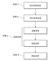
도 4는 제1 본 실시형태에 따른 이차 전지의 제조 공정을 나타내는 흐름도이다.
도 5는 제1 본 실시형태에 따른 이차 전지의 제조 공정 중 일 공정의 개략 단면도이다.
도 6은 제1 본 실시형태에 따른 이차 전지의 다른 제조 방법을 나타내는 흐름도이다.
도 7은 제2 본 실시형태에 따른 이차 전지의 개략 사시도이다.
도 8은 제3 본 실시형태에 따른 이차 전지의 개략 단면도이다.1 is a schematic cross-sectional view of a secondary battery according to a first present embodiment.
2 is a schematic cross-sectional view of an existing secondary battery.
3 is a schematic cross-sectional view of a secondary battery according to the first present embodiment.
4 is a flowchart showing the manufacturing process of the secondary battery according to the first present embodiment.
5 is a schematic cross-sectional view of one process among manufacturing processes of a secondary battery according to the first embodiment.
6 is a flowchart showing another manufacturing method of the secondary battery according to the first present embodiment.
7 is a schematic perspective view of a secondary battery according to a second present embodiment.
8 is a schematic cross-sectional view of a secondary battery according to a third present embodiment.
아래에서 도면을 참조하면서 본 발명의 실시형태(이하, '본 실시형태')에 대해 설명한다. 덧붙여 도면에서 동일 요소에는 동일한 부호를 붙였으며, 중복되는 설명은 생략했다. 또한 상하 좌우 등의 위치 관계는, 별도로 언급하지 않는 한 도면에 나타낸 위치 관계에 기초한다. 아울러 도면의 치수 비율은 도면에 나타낸 비율로 한정되지 않는다.EMBODIMENT OF THE INVENTION Embodiment of this invention (hereinafter, 'this embodiment') is described, referring drawings below. In addition, the same reference numerals are attached to the same elements in the drawings, and overlapping descriptions are omitted. In addition, positional relationships such as up, down, left, right, etc. are based on the positional relationships shown in the drawings unless otherwise specified. In addition, the dimensional ratio of the drawing is not limited to the ratio shown in the drawing.
[제1 본 실시형태][First Present Embodiment]
(이차 전지)(secondary battery)
도 1은, 제1 본 실시형태에 관한 이차 전지의 개략 단면도이다. 도 1에 나타낸 것처럼, 제1 본 실시형태에 관한 이차 전지(100)는, 음극 활물질을 갖지 않는 음극(120)과 음극(120)의 양면에 배치된 제1 세퍼레이터(110a) 및 제2 세퍼레이터(110b)를 갖는 시트(130)를 복수회 예각으로 번갈아 굽혀 형성하는 적층체(150)와, 시트를 굽힘으로써 서로 대향하는 세퍼레이터 사이에 형성되는 각 간극에 각각 배치되는 복수의 양극(140)을 포함한다.1 is a schematic cross-sectional view of a secondary battery according to a first present embodiment. As shown in FIG. 1 , the
(시트)(Sheet)
시트(130)는, 음극 활물질을 갖지 않는 음극(120)과 음극(120)의 양면에 배치된 제1 세퍼레이터(110a) 및 제2 세퍼레이터(110b)를 갖는다.The
(음극)(cathode)
음극(120)은, 음극 활물질을 갖지 않는다. 음극 활물질을 갖는 음극을 구비하는 이차 전지는, 그 음극 활물질의 존재로 인해 에너지 밀도를 향상시키기 어렵다. 한편, 본 실시형태에 따른 이차 전지(100)는, 음극 활물질을 갖지 않는 음극(120)을 구비하기 때문에 그러한 문제가 발생하지 않는다. 즉, 본 실시형태의 이차 전지(100)는, 금속이 음극(120)의 표면에 석출되고, 또 그 석출된 금속이 용해됨으로써 충방전이 행해지므로 에너지 밀도가 높다.
본 명세서에서 '음극 활물질'이란, 전지에서 전하 캐리어가 되는 금속 이온 또는 그 금속 이온에 대응하는 금속(이하, '캐리어 금속')을 음극(120)에 유지하기 위한 물질을 의미하며, 캐리어 금속의 호스트 물질로 바꿔 말할 수도 있다. 이러한 유지 기구로는, 별도로 한정하지 않으나 예를 들면, 인터칼레이션, 합금화, 금속 클러스터의 흡장 등을 들 수 있다. 본 명세서에서 음극 활물질은, 전형적으로는 리튬 금속 또는 리튬 이온을 음극(120)에 유지하기 위한 물질이다.In this specification, the term 'anode active material' means a material for maintaining a metal ion serving as a charge carrier in a battery or a metal corresponding to the metal ion (hereinafter, 'carrier metal') in the
이러한 음극 활물질로는, 별도로 한정하지 않으나 예를 들면, 탄소계 물질, 금속 산화물, 금속 또는 합금 등을 들 수 있다. 상기 탄소계 물질로는, 별도로 한정하지 않으나 예를 들면, 그래핀, 흑연, 하드 카본, 메조포러스 카본, 카본나노튜브, 카본나노혼 등을 들 수 있다. 상기 금속 산화물로는, 별도로 한정하지 않으나 예를 들면, 산화 티탄계 화합물, 산화 주석계 화합물, 산화 코발트계 화합물 등을 들 수 있다. 상기 금속 또는 합금으로는, 캐리어 금속과 합금화할 수 있는 것이라면 별도로 한정하지 않으나 예를 들면, 규소, 게르마늄, 주석, 납, 알루미늄, 갈륨, 및 이들을 포함하는 합금을 들 수 있다.Examples of the negative electrode active material include, but are not limited to, carbon-based materials, metal oxides, metals, or alloys. Examples of the carbon-based material include, but are not limited to, graphene, graphite, hard carbon, mesoporous carbon, carbon nanotube, carbon nanohorn, and the like. The metal oxide is not particularly limited, but examples thereof include titanium oxide-based compounds, tin oxide-based compounds, and cobalt oxide-based compounds. The metal or alloy is not particularly limited as long as it can be alloyed with the carrier metal, but examples thereof include silicon, germanium, tin, lead, aluminum, gallium, and alloys containing these.
음극(120)으로는, 음극 활물질을 갖지 않으며 집전체로서 사용할 수 있는 것이라면 별도로 한정하지 않으나 예를 들면, Cu, Ni, Ti, Fe 및, 그 밖에 Li과 반응하지 않는 금속, 이들의 합금, 스테인리스 강(SUS)으로 이루어진 그룹에서 선택되는 적어도 1종으로 이루어진 것을 들 수 있다. 덧붙여, 음극(120)으로 SUS를 이용하는 경우, SUS의 종류로는 기존에 알려진 다양한 것을 이용할 수 있다. 상기와 같은 음극 재료는 1종을 단독으로 또는 2종 이상을 병용하여 사용할 수 있다. 덧붙여, 본 명세서 중'Li과 반응하지 않는 금속'이란, 이차 전지(100)의 동작 조건에서, 리튬 이온 또는 리튬 금속과 반응하여 합금화하지 않는 금속을 의미한다.The
음극(120)은, 바람직하게는 리튬을 함유하지 않는 전극이다. 이러한 양태에 따르면 제조 시 가연성이 높은 리튬 금속을 사용하지 않아도 되므로, 이차 전지(100)는, 안전성 및 생산성이 더욱 우수해진다. 동일한 관점 및 음극(120)의 안전성 향상의 관점에서, 그중에서도 음극(120)은 Cu, Ni, 이들의 합금, 및 스테인리스강(SUS)으로 이루어지는 그룹에서 선택되는 적어도 1종으로 이루어지는 것이 보다 바람직하다. 마찬가지의 관점에서, 음극(120)은 Cu, Ni 또는 이들로 이루어진 합금으로 이루어진 것이 더욱 바람직하고, Cu 또는 Ni로 이루어진 것이 가장 바람직하다.The
본 명세서에서 '음극이 음극 활물질을 갖지 않는다'는 것은, 음극에서의 음극 활물질의 함유량이, 음극 전체에 대해 10질량% 이하인 것을 의미한다. 음극에서의 음극 활물질의 함유량은, 음극 전체에 대해, 5.0질량% 이하인 것이 바람직하고, 1.0질량% 이하가 보다 바람직하며, 0.1질량% 이하가 더욱 바람직하고, 0.0질량% 이하인 것이 가장 바람직하다. 아울러 이차 전지(100)가 음극 활물질을 갖지 않는 음극을 구비한다는 것은, 이차 전지(100)가, 일반적으로 이용되는 의미에서의 애노드 프리 이차 전지, 제로 애노드 이차 전지, 또는 애노드리스 이차 전지인 것을 의미한다.In this specification, 'a negative electrode does not have a negative electrode active material' means that the content of the negative electrode active material in the negative electrode is 10% by mass or less with respect to the entire negative electrode. The content of the negative electrode active material in the negative electrode is preferably 5.0% by mass or less, more preferably 1.0% by mass or less, still more preferably 0.1% by mass or less, and most preferably 0.0% by mass or less with respect to the total amount of the negative electrode. In addition, that the
음극(120)은, 바람직하게는 표면에, 석출되는 캐리어 금속과 음극의 접착성을 높이기 위한 접착층이 형성된다. 이러한 양태에 따르면, 음극(120) 상에 캐리어 금속, 특히 리튬 금속이 석출될 때, 음극(120)과 석출 금속의 접착성을 더욱 향상시킬 수 있다. 그 결과 음극(120)에서 석출 금속이 박리되는 것을 더욱 억제할 수 있어, 이차 전지(100)의 사이클 특성이 더욱 향상된다.The
접착층으로서는, 예를 들면 음극 이외의 금속, 그 합금, 탄소계 물질을 들 수 있다. 한정하려는 의도는 아니나, 접착층의 예로는 Au, Ag, Pt, Sb, Pb, In, Sn, Zn, Bi, Al, Sb, Pb, Ni, Cu, 그래핀, 흑연, 하드 카본, 메조포러스 카본, 카본나노튜브, 카본나노혼 등을 들 수 있다. 접착층의 두께는 별도로 한정하지 않으나, 1㎚ 이상 300㎚ 이하가 바람직하고, 50㎚ 이상 150㎚ 이하가 더욱 바람직하다. 접착층이 상기 양태이면, 더욱 더 음극(120)과 석출 금속의 접착성을 향상시킬 수 있다. 또한 접착층이 상술한 음극 활물질에 해당하는 경우, 접착층은 음극에 대해 10질량% 이하이며, 5.0질량% 이하인 것이 바람직하고, 1.0질량% 이하인 것이 보다 바람직하고, 0.1질량% 이하인 것이 더욱 바람직하다.Examples of the adhesive layer include metals other than the cathode, alloys thereof, and carbon-based materials. Although not intended to be limiting, examples of adhesive layers include Au, Ag, Pt, Sb, Pb, In, Sn, Zn, Bi, Al, Sb, Pb, Ni, Cu, graphene, graphite, hard carbon, mesoporous carbon, A carbon nanotube, a carbon nanohorn, etc. are mentioned. The thickness of the adhesive layer is not particularly limited, but is preferably 1 nm or more and 300 nm or less, and more preferably 50 nm or more and 150 nm or less. If the adhesive layer is of the above aspect, the adhesion between the
음극(120)의 평균 두께는, 4㎛ 이상 20㎛ 이하인 것이 바람직하고, 5㎛ 이상 18㎛ 이하인 것이 보다 바람직하며, 6㎛ 이상 15㎛ 이하인 것이 더욱 바람직하다. 이러한 양태에 따르면, 이차 전지(100)에서 음극(120)이 차지하는 부피가 감소하기 때문에, 이차 전지(100)의 에너지 밀도가 더욱 향상된다.The average thickness of the
(세퍼레이터)(separator)
제1 세퍼레이터(110a)는, 양극(140)과 음극(120)을 격리시켜 전지가 단락되는 것을 방지하면서, 양극(140)과 음극(120) 사이의 전하 캐리어가 되는 금속 이온의 이온 전도성을 확보하는 부재로, 도전성을 갖지 않으며, 금속 이온과 반응하지 않는 부재로 구성된다. 또한 전해액을 사용하는 경우에는, 제1 세퍼레이터(110a)는, 당해 전해액을 유지하는 역할도 담당한다. 제1 세퍼레이터(110a)는, 상기 역할을 담당하는 한 한정되지 않으나, 예를 들면 다공질의 폴리에틸렌(PE), 폴리프로필렌(PP), 또는 이들의 적층 구조에 의해 구성된다.The
제1 세퍼레이터(110a)는 세퍼레이터 피복층으로 피복될 수도 있다. 세퍼레이터 피복층은, 제1 세퍼레이터(110a)의 양쪽면을 피복할 수도 있고, 한쪽면만을 피복할 수도 있다. 세퍼레이터 피복층은, 인도 전도성을 가지며, 전하 캐리어가 되는 금속 이온과 반응하지 않는 부재라면 별도로 한정되지 않으나, 제1 세퍼레이터(110a)와, 제1 세퍼레이터(110a)에 인접한 층을 강고하게 접착시킬 수 있는 것이 바람직하다. 이러한 세퍼레이터 피복층으로는, 별도로 한정하지 않으나 예를 들면, 폴리비닐리덴 플루오라이드(PVDF), 스티렌 부타디엔 고무와 카복시메틸셀룰로스의 합재(SBR-CMC), 폴리아크릴산(PAA), 폴리아크릴산리튬(Li-PAA), 폴리이미드(PI), 폴리아미드이미드(PAI), 아라미드와 같은 바인더를 포함하는 것을 들 수 있다. 세퍼레이터 피복층은, 상기 바인더에 실리카, 알루미나, 티타니아, 지르코니아, 산화 마그네슘, 수산화 마그네슘 등의 무기 입자를 첨가시킬 수도 있다.The
제1 세퍼레이터(110a)의 평균 두께는 30㎛ 이하인 것이 바람직하고, 25㎛ 이하인 것이 보다 바람직하며, 20㎛ 이하인 것이 더욱 바람직하다. 이러한 양태에 따르면, 이차 전지(100)에서 제1 세퍼레이터(110a)가 차지하는 부피가 감소하기 때문에, 이차 전지(100)의 에너지 밀도가 더욱 향상된다. 또한 제1 세퍼레이터(110a)의 평균 두께는 3㎛ 이상인 것이 바람직하고, 5㎛ 이상인 것이 더욱 바람직하다. 이러한 양태에 따르면, 양극(140)과 음극(120)을 더욱 더 확실하게 격리할 수 있어, 전지가 단락되는 것을 더욱 억제할 수 있다.The average thickness of the
제2 세퍼레이터(110b)는, 제1 세퍼레이터(110a)의 구성으로서 상술한 구성을 가지고 있으면, 제1 세퍼레이터(110a)와 동일해도 상이해도 무방하다. 제2 세퍼레이터(110b)의 바람직한 양태는 제1 세퍼레이터(110a)와 동일하다.The
(적층체)(Laminate)
이차 전지(100)에서 적층체(150)는, 시트(130)를 복수의 굽힘부(160)에서 예각으로 굽혀 형성되며, 굽힘부(160) 및 평면부(170)가 적층 방향(Z)을 향해 번갈아 접속되는 지그재그 구조(또는 '꾸불꾸불한 구조'라고도 함)를 갖는다. 여기서 '굽힘부(160)에서 예각으로 굽힌다'란, 굽힘부(160)에 연결된 두 개의 평면부(170)가 이루는 각도가 예각인 것을 의미한다. 적층체(150)는, 굽힘부(160)에서, 당해 굽힘부(160)에 연결된 두 개의 평면부(170)가 이루는 각도가 약 0도가 되는 굽힘부(160)를 갖는 것이 바람직하다. 즉, 적층체(150)는, 인접하는 평면부(170)끼리가 거의 평행해지도록 굽혀진다. 이러한 양태에 따르면, 적층체(150)의 적층수를 더욱 늘릴 수 있다.In the
덧붙여 적층체(150)의 적층수란, 시트(130)를 굽힌 횟수를 의미하며, 굽힘부(160)의 수와 일치한다. 예를 들어, 시트(130)를 3회 굽혀서 형성된 적층체(150)는, 네 개의 평면부(170)와 세 개의 굽힘부(160)를 가지며, 그 적층수는 3이다.Incidentally, the number of layers of the laminate 150 means the number of times the
적층체(150)의 굽힘부(160)에서, 당해 굽힘부(160)에 연결된 두 개의 평면부(170)의 이루는 각도는, 0도 이상일 수도 있고, 1도 이상일 수도 있고, 3도 이상일 수도 있고, 5도 이상일 수도 있고, 10도 이상일 수도 있고, 15도 이상일 수도 있다. 적층체(150)의 굽힘부(160)에서, 당해 굽힘부(160)에 연결된 두 개의 평면부(170)가 이루는 각도는, 40도 이하일 수도 있고, 30도 이하일 수도 있고, 20도 이하일 수도 있고, 18도 이하일 수도 있다.In the
이차 전지(100)에서, 그 적층수는 2 이상이며, 즉, 세 개의 평면부(170)와, 두 개의 굽힘부(160)를 갖는 적층체를 구비한다. 이차 전지(100)의 적층수는, 3 이상인 것이 바람직하며, 5 이상인 것이 보다 바람직하고, 10 이상인 것이 더욱 바람직하다. 이차 전지(100)의 적층수가 상기 범위 내에 있음으로써, 이차 전지(100)의 용량이 더욱 향상된다. 이차 전지(100)의 적층수의 상한은 별도로 한정하지 않으나, 그 적층수는 50 이하일 수도 있고, 40 이하일 수도 있고, 30 이하일 수도 있다. 이차 전지(100)의 적층수가 상기 범위에 있으면, 생산성이 더욱 향상된다.In the
도 2는 기존의 이차 전지의 개략 단면도이다. 도 2에 나타낸 것처럼, 기존의 이차 전지(200)는, 양극(210), 세퍼레이터(220), 음극 활물질을 갖는 음극(230)이 복수 적층된 구조를 갖는다. 기존의 이차 전지(200)는, 아래와 같이 자동 적층 장치로 자동으로 적층할 수 있으나, 음극(230)이 갖는 음극 활물질의 존재로 인해 에너지 밀도가 낮다.2 is a schematic cross-sectional view of a conventional secondary battery. As shown in FIG. 2 , the conventional
기존의 이차 전지(200)를 자동 적층 장치로 자동으로 적층하는 경우의 프로세스는 다음과 같다. 먼저, 양극(210), 세퍼레이터(220), 음극(230)을 복수 장 준비하고, 각 종류별로 자동 적층 장치의 소정 위치에 세팅한다. 그 다음, 자동 적층 장치는 소정의 위치에 세팅된 양극(210) 중 한 장을 꺼낸다. 자동 적층 장치는 마찬가지로, 소정의 위치에 세팅된 세퍼레이터(220) 및 음극(230)을 한 장씩 꺼내, 이들을 상기 순서로 적층함으로써 양극(210)과 세퍼레이터(220)와 음극(230)이 적층된 구조를 얻는다. 상기 적층 절차를 반복함으로써, 도 2에 나타낸 양극(210), 세퍼레이터(220), 음극(230)이 복수 적층된 구조를 얻을 수 있다.A process for automatically stacking the existing
한편, 에너지 밀도를 향상시키기 위해, 음극 활물질을 갖는 음극(230) 대신 음극 활물질을 갖지 않는 음극을 이용하여 이차 전지를 제조하는 경우, 상기 방법과 동일한 자동 적층에 의해 양극, 세퍼레이터, 음극의 적층 구조를 형성하면, 음극 활물질을 갖지 않는 음극이 매우 얇아 다루기 어렵기 때문에, 적층된 음극에 주름이 발생하게 된다. 이와 같이 음극에 주름이 발생한 경우, 음극 상에 석출된 캐리어 금속은 음극과의 접착성이 불충분하여, 이차 전지의 사용 시, 음극 상에 석출된 캐리어 금속이 음극으로부터 벗겨지기 쉬워진다. 그 결과, 이러한 이차 전지는 사이클 특성이 떨어진다.Meanwhile, in order to improve energy density, when a secondary battery is manufactured by using a negative electrode without a negative electrode active material instead of the
도 1의 제1 본 실시형태에 따른 이차 전지(100)는, 매우 얇아 다루기 어려운 음극(120)이 단일체로 적층되어 있는 것이 아니라, 음극(120)과 음극(120)의 양면에 배치되는 제1 세퍼레이터(110a) 및 제2 세퍼레이터(110b)가 일체로 된 시트(130)가 적층된 적층체(150)를 구비한다. 시트(130)는, 음극(120), 제1 세퍼레이터(110a) 및 제2 세퍼레이터(110b)를 포함하기 때문에, 그 평균 두께가 음극(120)의 평균 두께보다 두꺼워, 다루기 쉽다. 또한 음극(120)은, 제1 세퍼레이터(110a) 및 제2 세퍼레이터(110b) 사이에 끼워져, 양쪽면에서 물리적 압력이 가해지기 때문에 주름이 생기기 어렵다. 그 결과, 이차 전지(100)는 음극(120)에 주름이 발생하는 것을 억제하면서도 자동 적층 장치로 형성할 수 있기 때문에, 사이클 특성이 우수하고 생산성이 높다.In the
(양극)(anode)
도 1에 나타낸 것처럼 이차 전지(100)에서 양극(140)은, 시트(130)를 굽혀 형성된 각 간극에 각각 배치된다. 보다 상세하게는, 양극(140)은 서로 인접하는 평면부(170) 사이에 각각 배치된다. 어느 평면부(170)(제1 평면부(170))와 제1 평면부(170)의 적층 방향(Z)에 인접하는 평면부(170)(제2 평면부(170)) 사이에 배치된 양극(140)은, 한쪽 면이 제1 평면부(170)에 속한 제1 세퍼레이터(110a)와 대향하며, 다른쪽 면이 제2 평면부(170)에 속한 제1 세퍼레이터(110a)와 대향한다. 제1 평면부(170)와, 제1 평면부(170)의 적층 방향(Z)의 반대 방향에 인접하는 평면부(170)(제3 평면부(170)) 사이에 배치된 양극(140)은, 한쪽 면이 제1 평면부(170)에 속한 제2 세퍼레이터(110b)와 대향하며, 다른쪽 면이 제3 평면부(170)에 속한 제2 세퍼레이터(110b)와 대향한다.As shown in FIG. 1 , in the
양극(140)은, 상술한 것처럼 서로 인접하는 평면부(170) 사이에 각각 배치되기 때문에, 양극(140)의 양쪽면에서, 제1 세퍼레이터(110a) 또는 제2 세퍼레이터(110b)를 통해 음극(120)과 대향한다. 또한 이차 전지(100)는 복수의 양극(140)을 구비할 수 있다. 그 결과, 이차 전지(100)의 용량이 향상된다.Since the
도 1에서 양극(140)은, 적층체(150)의 굽힘부(160)의 단부(굽힘 단부)(180)로부터, 바람직하게는 0.01㎜ 이상 5.00㎜ 이하의 범위로 이격되도록 배치된다. 즉, 양극(140)과 굽힘 단부(180) 사이의 거리 d는, 0.01mm 이상 5.00mm 이하인 것이 바람직하다. 거리 d가 0.01mm 이상이면, 양극(140)의 위치 결정에 필요한 시간이 짧아져 이차 전지(100)의 생산성이 더욱 향상된다. 또한 거리 d가 5.00mm 이하이면, 양극(140)과 음극(120)의 대향하는 면적이 더욱 증가하여 이차 전지(100)의 에너지 밀도 및 용량이 더욱 향상된다. 마찬가지의 관점에서 거리 d는, 0.05mm 이상 4.00mm 이하인 것이 바람직하며, 0.10mm 이상 3.00mm 이하인 것이 더욱 바람직하다.In FIG. 1 , the
덧붙여, 양극(140)과 굽힘 단부(180)의 거리 d는 아래와 같이 측정할 수 있다. 먼저, 이차 전지(100)를 적층 방향(Z)에 평행하면서 적어도 하나의 굽힘부(160)에 수직인 면으로 절단한다. 생성된 절단면을, 육안, 광학 현미경 또는 전자 현미경 등의 방법을 사용하여 관찰하여, 적어도 두 개 이상의 양극(140)에 대해 양극(140)과 굽힘 단부(180) 사이의 거리 d를 측정한다. 측정 결과의 상가 평균을 구함으로써, 양극(140)과 굽힘 단부(180)의 거리 d를 구할 수 있다. 굽힘 단부(180)는, 이차 전지(100)의 절단면에 있어서, 굽힘부(160) 중 양극(140)과의 거리가 가장 긴 점이다. 바꿔 말하면, 이차 전지(100)의 절단면에 있어서, 양극(140)과 굽힘부(160) 상의 임의의 점과의 거리를 d'라고 했을 때, d'가 최대가 되는 굽힘부(160) 상의 점이 굽힘 단부(180)이다.In addition, the distance d between the
양극(140)으로는, 일반적으로 이차 전지에 사용되는 것이라면 별도로 한정하지 않으나, 이차 전지의 용도 및 캐리어 금속의 종류에 따라, 알려진 재료를 적절히 선택할 수 있다. 이차 전지의 안정성 및 출력 전압을 높이는 관점에서, 양극(140)은 양극 활물질을 갖는 것이 바람직하다.The
본 명세서에서 '양극 활물질'이란, 캐리어 금속을 양극(140)에 유지하기 위한 물질을 의미하며, 캐리어 금속의 호스트 물질로 바꿔 말할 수도 있다. 본 명세서에서 양극 활물질은, 전형적으로는 리튬 이온을 양극(140)에 유지하기 위한 물질이다.In this specification, the 'cathode active material' refers to a material for maintaining a carrier metal in the
이러한 양극 활물질로는, 별도로 한정하지 않으나 예를 들면, 금속 산화물 및 금속 인산염을 들 수 있다. 상기 금속 산화물로는, 별도로 한정하지 않으나 예를 들면, 산화 코발트계 화합물, 산화 망간계 화합물, 산화 니켈계 화합물 등을 들 수 있다. 상기 금속 인산염으로는, 별도로 한정하지 않으나 예를 들면, 인산 철계 화합물 및 인산 코발트계 화합물을 들 수 있다. 캐리어 금속이 리튬 이온인 경우, 전형적인 양극 활물질로는, LiCoO2, LiNixCoyMnzO(x+y+z=1), LiNixMnyO(x+y=1), LiNiO2, LiMn2O4, LiFePO, LiCoPO, LiFeOF, LiNiOF, TiS2를 들 수 있다. 상기와 같은 양극 활물질은, 1종을 단독으로 또는 2종 이상을 병용하여 사용할 수 있다. Examples of such a cathode active material include, but are not limited to, metal oxides and metal phosphates. The metal oxide is not particularly limited, but examples thereof include cobalt oxide-based compounds, manganese oxide-based compounds, and nickel oxide-based compounds. The metal phosphate is not particularly limited, but examples thereof include iron phosphate-based compounds and cobalt phosphate-based compounds. When the carrier metal is lithium ion, typical positive electrode active materials include LiCoO 2 , LiNi x Co y Mn z O (x+y+z=1), LiNi x Mn y O (x+y=1), LiNiO 2 , and LiMn 2 O 4 , LiFePO, LiCoPO, LiFeOF, LiNiOF, and TiS 2 . The above positive electrode active materials may be used singly or in combination of two or more.
양극(140)은, 상기 양극 활물질 이외의 성분을 포함할 수도 있다. 이러한 성분으로는, 별도로 한정하지 않으나 예를 들면, 알려진 전도 보조제, 바인더, 고체 폴리머 전해질, 무기 고체 전해질을 들 수 있다.The
양극(140)에서 전도 보조제로는, 별도로 한정하지 않으나 예를 들면, 카본 블랙, 단층 카본나노튜브(SW-CNT), 다층 카본나노튜브(MW-CNT), 카본나노파이버, 아세틸렌 블랙 등을 들 수 있다. 또한 바인더로는, 별도로 한정하지 않으나 예를 들면, 폴리비닐리덴 플루오라이드, 폴리테트라플루오로에틸렌, 스티렌 부타디엔 고무, 아크릴 수지, 폴리이미드 수지 등을 들 수 있다.Examples of the conduction aid in the
양극(140)에서 양극 활물질의 함유량은, 양극(140) 전체에 대해, 예를 들면 50질량% 이상 100질량% 이하일 수 있다. 전도 보조제의 함유량은, 양극(140) 전체에 대해, 예를 들면 0.5질량%30질량% 이하일 수 있다. 바인더의 함유량은, 양극(140) 전체에 대해, 예를 들면 0.5질량%30질량% 이하일 수 있다. 고체 폴리머 전해질 및 무기 고체 전해질의 함유량의 합계는, 양극(140) 전체에 대해, 예를 들면 0.5질량%30질량% 이하일 수 있다.The content of the positive electrode active material in the
(전해액)(electrolyte)
이차 전지(100)는 전해액을 가질 수 있다. 전해액은 제1 세퍼레이터(110a) 및/또는 제2 세퍼레이터(110b)에 침지시킬 수도 있고, 적층체(150)와 함께 전해액을 밀봉한 것을 이차 전지(100)로 할 수도 있다. 전해액은, 전해질 및 용매를 함유하며 이온 전도성을 갖는 용액으로, 리튬 이온의 도전 경로로서 작용한다. 따라서, 전해액을 갖는 이차 전지(100)는 내부 저항이 더욱 저하되어, 에너지 밀도, 용량, 사이클 특성이 더욱 향상된다.The
전해질은, 염이라면 별도로 한정하지 않으나 예를 들면, Li, Na, K, Ca, Mg의 염 등을 들 수 있다. 전해질로는 리튬염을 사용하는 것이 바람직하다. 리튬염으로는 별도로 한정하지 않으나, LiI, LiCl, LiBr, LiF, LiBF4, LiPF6, LiAsF6, LiSO3CF3, LiN(SO2F)2, LiN(SO2CF3)2, LiN(SO2CF3CF3)2, LiB(O2C2H4)2, LiB(O2C2H4)F2, LiB(OCOCF3)4, LiNO3, Li2SO4 등을 들 수 있다. 이차 전지(100)의 에너지 밀도, 용량, 사이클 특성을 더욱 더 우수하게 한다는 관점에서 리튬염은, LiN(SO2F)2인 것이 바람직하다. 아울러 상기 리튬염은 1종을 단독으로 또는 2종 이상을 병용하여 사용할 수 있다.The electrolyte is not particularly limited as long as it is a salt, but examples thereof include salts of Li, Na, K, Ca, and Mg. It is preferable to use a lithium salt as an electrolyte. Lithium salts are not particularly limited, but LiI, LiCl, LiBr, LiF, LiBF 4 , LiPF 6 , LiAsF 6 , LiSO 3 CF 3 , LiN(SO 2 F) 2 , LiN(SO 2 CF 3 ) 2 , LiN( SO 2 CF 3 CF 3 ) 2 , LiB(O 2 C 2 H 4 ) 2 , LiB(O 2 C 2 H 4 )F 2 , LiB(OCOCF 3 ) 4 , LiNO 3 , Li 2 SO 4 and the like. there is. From the viewpoint of further improving the energy density, capacity, and cycle characteristics of the
용매로서는 별도로 한정하지 않으나 예를 들면, 디메틸에테르, 디에틸렌글리콜 디메틸에테르, 트리에틸렌글리콜 디메틸에테르, 아세토니트릴, 탄산디메틸, 탄산디에틸, 탄산에틸메틸, 에틸렌 카보네이트, 프로필렌 카보네이트, 클로로에틸렌 카보네이트, 플루오로에틸렌 카보네이트, 디플루오로에틸렌 카보네이트, 트리플루오로메틸 프로필렌 카보네이트, 메틸아세테이트, 에틸아세테이트, 프로필아세테이트, 메틸프로피오네이트, 에틸프로피오네이트, 노나플루오로부틸메틸에테르, 노나플루오로부틸에틸테르, 테트라플루오로에틸 테트라플루오로프로필에테르, 인산 트리메틸, 인산 트리에틸을 들 수 있다. 상기와 같은 용매는 1종을 단독으로 또는 2종 이상을 병용하여 사용할 수 있다.The solvent is not particularly limited, but examples thereof include dimethyl ether, diethylene glycol dimethyl ether, triethylene glycol dimethyl ether, acetonitrile, dimethyl carbonate, diethyl carbonate, ethyl methyl carbonate, ethylene carbonate, propylene carbonate, chloroethylene carbonate, and fluorocarbons. Roethylene carbonate, difluoroethylene carbonate, trifluoromethyl propylene carbonate, methyl acetate, ethyl acetate, propyl acetate, methyl propionate, ethyl propionate, nonafluorobutylmethyl ether, nonafluorobutylethyl ether, tetrafluoroethyl tetrafluoropropyl ether, trimethyl phosphate, and triethyl phosphate. These solvents can be used individually by 1 type or in combination of 2 or more types.
(양극 단자 및 음극 단자)(positive terminal and negative terminal)
도 3은 제1 본 실시형태에 따른 이차 전지의 개략 사시도이다. 도 3에 나타낸 것처럼 제1 본 실시형태에 따른 이차 전지(100)는, 적층체(150)의 평면부(170) 상에, 적어도 하나의 음극 단자(310)를 구비한다. 또한 이차 전지(100)는, 각각의 양극에 양극 단자(320)를 구비한다. 음극 단자(310) 및 양극 단자(320)는 각각 외부 회로에 연결된다. 음극 단자(31) 및 양극 단자(320)의 재료로는, 도전성이 있는 것이라면 별도로 한정하지 않으나, 예를 들면 Al, Ni 등을 들 수 있다.3 is a schematic perspective view of the secondary battery according to the first present embodiment. As shown in FIG. 3 , the
(이차 전지의 사용)(Use of secondary battery)
이차 전지(100)는, 음극 단자(310)를 외부 회로의 한쪽 끝에, 양극 단자(320)를 외부 회로의 다른쪽 끝에 연결함으로써 충방전된다. 덧붙여, 음극 단자(310)가 복수 존재하는 경우, 모든 음극 단자(310)가 동일 전위가 되도록 외부 회로에 연결된다. 또한 양극 단자(320)도 마찬가지로, 모든 양극 단자(320)가 동일 전위가 되도록 외부 회로에 연결된다.The
양극 단자(320)와 음극 단자(310) 사이에는, 음극 단자(310)로부터 외부 회로를 통해 양극 단자(320)로 전류가 흐르는듯한 전압을 인가함으로써 이차 전지(100)가 충전된다. 이차 전지(100)를 충전함으로써, 음극(120)과 제1 세퍼레이터(110a)의 계면, 및 음극(120)과 제2 세퍼레이터(110b)의 계면에 캐리어 금속이 석출된다. 석출되는 캐리어 금속으로는, 리튬 금속이 전형적이다. 이차 전지(100)에서의 음극(120)은 주름 발생이 억제되고 있으므로, 석출된 캐리어 금속은 음극(120)과의 접착성이 우수하다. 그 결과, 음극(120) 상에 석출된 캐리어 금속은 음극으로부터 벗겨지기 어려워, 이차 전지(100)는 사이클 특성이 우수해진다.Between the
이차 전지(100)는, 초기 충전에 의해 음극(120)과 제1 세퍼레이터(110a)의 계면, 및/또는 음극(120)과 제2 세퍼레이터(110b)의 계면에 고체 전해질 계면층(SEI층)이 형성될 수도 있다. 형성되는 SEI층은, 별도로 한정하지 않으나 예를 들면, 캐리어 금속의 무기물 및 캐리어 금속의 유기물을 포함할 수 있다. 전형적으로는, 리튬을 포함하는 무기 화합물 및 리튬을 포함하는 유기 화합물 등을 포함할 수 있다. SEI층의 전형적인 평균 두께는 1nm 이상 10㎛ 이하이다. In the
이차 전지(100)에 SEI층이 형성되어 있는 경우, 이차 전지(100)의 충전 시에 석출되는 캐리어 금속은, 음극(120)과 SEI층의 계면에 석출될 수도 있고, SEI층과 제1 세퍼레이터(110a)의 계면에 석출될 수도 되고, SEI층과 제2 세퍼레이터(110b)의 계면에 석출될 수도 있다. When the SEI layer is formed on the
충전 후의 이차 전지(100)에 대해, 양극 단자(320) 및 음극 단자(310)를 연결하면 이차 전지(100)가 방전된다. 음극(120)과 SEI층의 계면, SEI층과 제1 세퍼레이터(110a)의 계면, SEI층과 제2 세퍼레이터(110b)의 계면 중 적어도 어느 하나에 생긴 캐리어 금속의 석출이 용해된다.When the
(이차 전지의 제조 방법)(Method of manufacturing secondary battery)
본 실시형태의 이차 전지의 제조 방법은, 음극 활물질을 갖지 않는 음극과 음극의 양면에 배치된 세퍼레이터를 갖는 시트를 준비하는 공정과, 시트를 복수회 예각으로 번갈아 굽혀 형성하는 적층체와, 시트를 굽힘으로써 서로 대향하는 세퍼레이터 사이에 형성되는 각 간극에 각각 배치되는 복수의 양극을 포함하는 성형체를 성형하는 성형 공정을 포함한다. 도 4는 도 1에 나타낸 제1 본 실시형태에 따른 이차 전지(100)의 제조 방법의 흐름도를 나타낸다. 이하, 각 단계에 대해 설명한다.The secondary battery manufacturing method of the present embodiment includes a step of preparing a sheet having a negative electrode having no negative electrode active material and a separator disposed on both sides of the negative electrode, a laminate formed by alternately bending the sheet at an acute angle a plurality of times, and a sheet. and a molding step of molding a molded body including a plurality of anodes respectively disposed in respective gaps formed between separators facing each other by bending. FIG. 4 shows a flowchart of a method for manufacturing the
(시트 준비 공정)(sheet preparation process)
본 실시형태의 이차 전지의 제조 방법에서는, 첫째로 음극 활물질을 갖지 않는 음극과 음극의 양면에 배치된 세퍼레이터를 갖는 시트를 준비한다(시트 준비 공정, 단계 1). 시트 준비 공정은, 음극에 주름이 생기지 않는 방법으로 음극의 양면에 세퍼레이터를 배치하는 공정이라면 별도로 한정하지 않으나, 예를 들면 롤-투-롤(roll-to-roll)법을 사용할 수 있다.In the secondary battery manufacturing method of the present embodiment, first, a negative electrode having no negative electrode active material and a sheet having separators disposed on both sides of the negative electrode are prepared (sheet preparation step, step 1). The sheet preparation process is not particularly limited as long as it is a process of arranging separators on both sides of the negative electrode in a way that does not cause wrinkles on the negative electrode, but for example, a roll-to-roll method can be used.
롤-투-롤법은, 예를 들면 다음과 같이 할 수 있다. 즉, 음극(120)을 구성하는 재료를 포함하는 시트(이하, '음극 시트')가 감긴 롤과, 제1 세퍼레이터(110a)를 구성하는 재료를 포함하는 시트(이하, '제1 세퍼레이터 시트')가 감긴 롤과, 제2 세퍼레이터(110b)를 구성하는 재료를 포함하는 시트(이하, '제2 세퍼레이터 시트')가 감긴 롤을 준비한다. 이들 롤을 소정의 장치에 설치하고 각 롤을 시트 형태로 되돌리면서, 음극 시트를 제1 세퍼레이터 시트 및 제2 세퍼레이터 시트 사이에 끼우고, 시트의 두께 방향으로 가압함으로써, 음극 시트의 양면에 제1 세퍼레이터 시트 및 제2 세퍼레이터 시트가 배치된 시트를 형성한다. 생성된 시트는, 롤 형태로 감겨 다음 공정에 제공할 수 있다.The roll-to-roll method can be carried out as follows, for example. That is, a roll on which a sheet containing the material constituting the negative electrode 120 (hereinafter referred to as 'negative electrode sheet') is wound, and a sheet containing the material constituting the
시트 준비 공정에서 롤-투-롤법을 사용하면, 음극 시트를 면 방향으로 끌어당기면서도 음극 시트의 양면에 제1 세퍼레이터 시트 및 제2 세퍼레이터 시트가 배치된 시트를 형성할 수 있기 때문에, 음극 시트에 주름이 생기기 어렵다. 또한 생성된 시트를 롤 형태로 감기 때문에, 그 후의 공정에 제공하기가 용이하여 생산성이 더욱 우수하다.If the roll-to-roll method is used in the sheet preparation process, it is possible to form a sheet in which the first separator sheet and the second separator sheet are disposed on both sides of the negative electrode sheet while pulling the negative electrode sheet in the plane direction, so that the negative electrode sheet Hard to wrinkle. In addition, since the produced sheet is wound into a roll form, it is easy to use in the subsequent process and the productivity is further excellent.
덧붙여 음극 시트는, 음극(120)과 동일한 두께일 수도 있고 음극(120)보다 두꺼울 수도 있다. 음극 시트가 음극(120)보다 두꺼운 경우, 음극 시트를 제1 세퍼레이터 시트 및 제2 세퍼레이터 시트 사이에 끼우는 공정 전에, 음극 시트를 압연하여 이를 통해 음극 시트를 얇게 만들 수 있다.Incidentally, the negative electrode sheet may have the same thickness as the
시트 준비 공정은, 음극과 음극의 양면에 배치된 세퍼레이터를 갖는 시트를 형성하기 전 및/또는 후에, 세정 공정 및 건조 공정을 포함할 수도 있다. 세정 공정으로는, 예를 들면 음극 시트를, 설파믹산을 포함하는 용제로 세정한 후, 에탄올로 초음파 세정하는 공정 등을 들 수 있다.The sheet preparation process may include a cleaning process and a drying process before and/or after forming the sheet having the negative electrode and the separator disposed on both sides of the negative electrode. As the cleaning step, for example, a step of ultrasonic cleaning with ethanol after cleaning the negative electrode sheet with a solvent containing sulfamic acid, and the like are exemplified.
(양극 준비 공정)(Anode preparation process)
다음으로, 도 4에 나타낸 것처럼 양극(140)을 준비한다(양극 준비 공정, 단계 2). 양극(140)의 제조 방법으로는, 상술한 양극(140)을 얻을 수 있는 방법이라면 별도로 한정하지 않으나 예를 들면, 양극 활물질, 알려진 전도 보조제, 알려진 바인더를 혼합하여 얻어진 양극 혼합물을, 예를 들면 5㎛ 이상 1㎜ 이하의 금속 포일(예를 들어, Al 포일)의 한쪽 면에 도포하고 프레스 성형하여 얻을 수도 있다. 또는 시판되는 이차 전지용 양극을 사용할 수도 있다.Next, as shown in FIG. 4 , the
(성형 공정)(Forming process)
다음으로, 도 4에 나타낸 것처럼 생성된 시트를 복수회 예각으로 번갈아 굽혀 형성된 적층체와, 시트를 굽힘으로써 서로 대향하는 세퍼레이터 사이에 형성되는 각 간극에 각각 배치되는 복수의 양극을 포함하는 성형체를 성형한다(성형 공정, 단계 3).Next, as shown in FIG. 4, a laminated body formed by alternately bending the produced sheet at an acute angle a plurality of times and a molded body including a plurality of anodes disposed in respective gaps formed between the separators facing each other by bending the sheet is molded. (forming process, step 3).
이와 같이 성형 공정은, 적당한 두께 및 기계 강도를 갖는 시트를 사용하여 형성되는 적층체와, 그 적층체의 각 간극에 배치되는 양극을 포함하는 성형체를 성형하기 때문에, 그 성형 시에 자동 적층 장치를 사용해도 음극에 주름이 생기기 어렵다. 즉, 음극에 주름을 발생시키지 않으면서 자동적으로 성형체를 성형하는 것이 가능하다. 따라서, 본 실시형태의 이차 전지의 제조 방법은, 사이클 특성이 우수한 이차 전지를 높은 생산성으로 제조할 수 있다.In this forming process, since a molded body including a laminate formed using a sheet having an appropriate thickness and mechanical strength and an anode disposed in each gap of the laminate is molded, an automatic lamination device is used during the molding. Even if it is used, wrinkles are unlikely to form on the cathode. That is, it is possible to automatically mold a molded body without generating wrinkles in the cathode. Therefore, the secondary battery manufacturing method of the present embodiment can produce a secondary battery with excellent cycle characteristics with high productivity.
도 5에 성형 공정의 일 양태를 나타낸다. 일 실시형태의 성형 공정에서, 먼저 적층체의 적층 방향(Z)에 수직인 제1 방향(X1)으로 시트(130)에 제1 평판(500)을 밀어넣고, 제1 방향과 반대인 제2 방향(X2)으로 시트(130)에 제2 평판(510)을 밀어넣으면서, 시트(130)를 적층체의 적층 방향(Z)의 반대 방향으로 가압하여, 이를 통해 시트(130)를 굽힌다. 여기서 제1 평판(500)은, 양극(140) 및 양극(140)과 일체화된 제1 기판(520)을 포함하고, 제2 평판(510)은 양극(140) 및 양극(140)과 일체화된 제2 기판(530)을 포함한다. 그 후, 제1 기판(520) 및 제2 기판(530)을 제거한다. 이러한 양태에 따르면, 도 1의 적층체(150) 형성과, 양극(140) 삽입을 동시에 진행할 수 있기 때문에, 생산성이 더욱 향상된다.5 shows one aspect of the molding process. In the molding process of one embodiment, first, the first
또한 상기와 같이 하여 시트(130)를 굽힐 때에는, 시트(130)의 장축 방향의 한쪽 끝을 고정하고 다른쪽 끝을 끌어당겨, 이를 통해 시트(130)의 장축 방향에 장력을 작용시키는 것이 바람직하다. 이러한 양태에 따르면, 시트(130)가 느슨해지는 것을 방지할 수 있기 때문에, 음극(120)에 주름이 생기는 것을 더욱 억제할 수가 있다. 시트(130)의 장축 방향으로 인가하는 장력으로는, 시트(130)의 두께 등에 따라 적절히 조정할 수 있으나, 예를 들면 0.1kgf 이상 10.0kgf 이하일 수 있다.In addition, when bending the
제1 평판(500)에서, 양극(140)과 제1 기판(520)을 일체화시키는 방법으로는, 별도로 한정하지 않으나 예를 들면, 양극(140)을 제1 기판(520) 상에 싣는 방법일 수도 있고, 흡인 장치에 연결된 제1 기판(520)을 이용하여 양극(140)을 흡착하는 방법일 수도 있다. 흡인 장치에 연결된 제1 기판(520)을 이용하여 양극(140)을 흡착하는 방법을 이용하는 경우, 제1 기판(520)을 제거하기 전에 양극(140)의 흡착을 해제할 필요가 있다.In the first
도 6에 나타낸 것처럼, 다른 실시형태에서 성형 공정은, 도 1의 시트(130)를 굽힘으로써 도 1의 적층체(150)를 형성하는 굽힘 공정과, 도 1의 시트(130)를 굽혀 형성하는 각 간극에 도 1의 양극(140)을 각각 삽입하는 삽입 공정을 포함할 수도 있다.As shown in FIG. 6, in another embodiment, the forming process includes a bending process of forming the
굽힘 공정은, 적층체의 적층 방향에 수직인 제1 방향으로 시트(130)에 제1 평판을 밀어넣고, 제1 방향과 반대인 제2 방향으로 시트(130)에 제2 평판을 밀어넣으면서, 시트(130)를 적층체의 적층 방향의 반대 방향으로 가압하여 이를 통해 시트(130)를 굽히고, 추가로 그 후에 제1 평판 및 제2 평판을 제거하는 공정이다. 굽힘 공정을 통해, 도 1에 나타낸 적층체(150)를 얻을 수 있다.In the bending process, while pushing a first flat plate into the
삽입 공정은, 굽힘 공정에서 얻어진 도 1의 적층체(150)의 각 간극에 양극(140)을 삽입하는 공정이다. 즉, 삽입 공정에서 양극(140)은 서로 인접하는 평면부(170) 사이에 각각 삽입된다.The insertion step is a step of inserting the
(봉입 공정)(encapsulation process)
다음으로, 도 4 및 도 6에 나타낸 것처럼 복수의 양극(140)이 적층체(150)의 각 간극에 배치된 성형체를 밀폐 용기에 봉입함으로써 봉입체를 얻고, 이를 이차 전지(100)로 한다(봉입 공정, 단계 4). 봉입 공정에서, 전해액을 밀폐 용기에 봉입할 수도 있다. 이와 같이 전해액을 봉입함으로써 이차 전지(100)의 내부 저항이 한층 저하되기 때문에, 이차 전지(100)의 에너지 밀도, 용량, 사이클 특성은 더욱 더 우수해진다.Next, as shown in FIGS. 4 and 6, a molded body in which a plurality of
봉입 공정에서의 밀폐 용기로는, 별도로 한정하지 않으나 예를 들면 라미네이트 필름을 들 수 있다.Although it does not specifically limit as an airtight container in the sealing process, For example, a laminated film is mentioned.
[제2 본 실시형태][Second present embodiment]
(이차 전지)(secondary battery)
도 7은 제2 본 실시형태에 따른 이차 전지의 개략 사시도이다. 도 7에 나타낸 것처럼, 제2 본 실시형태에 따른 이차 전지(700)는, 적층체(150)의 각각의 평면부(170)에 음극 단자(310)를 구비한다. 또한 이차 전지(700)는 각각의 양극에 양극 단자(320)를 구비한다. 이차 전지(700)에서 복수의 음극 단자(310)는, 모든 음극 단자(310)가 동일 전위가 되도록 외부 회로에 연결된다.7 is a schematic perspective view of a secondary battery according to a second present embodiment. As shown in FIG. 7 , the
이러한 양태에 따르면, 음극(120)에 복수의 음극 단자(310)를 갖고, 이 음극 단자(310)가 동전위가 되도록 연결되기 때문에, 음극(120)이 더욱 용이하게 동일 전위로 유지되어, 이차 전지(700)의 내부 저항이 더욱 감소된다. 그 결과, 이차 전지(700)의 에너지 밀도, 용량, 사이클 특성은 더욱 우수해진다.According to this aspect, since the
이차 전지(700)는, 상술한 것 이외에는 제1 본 실시형태에 따른 이차 전지(100)와 마찬가지의 구성을 가지며 동일한 효과를 발휘한다.The
[제3 본 실시형태][Third present embodiment]
(이차 전지)(secondary battery)
도 8은 제3 실시형태에 따른 이차 전지의 개략 단면도이다. 도 8에 나타낸 것처럼 제3 본 실시형태에 따른 이차 전지(800)는, 음극 활물질을 갖지 않는 음극(120)과 음극(120)의 양면에 배치된 제1 고체 전해질(810a) 및 제2 고체 전해질(810b)을 갖는 시트(820)를 복수회 예각으로 번갈아 굽혀 형성하는 적층체(830)와, 시트를 굽힘으로써 서로 대향하는 세퍼레이터 사이에 형성되는 각 간극에 각각 배치되는 복수의 양극(140)을 구비한다. 즉, 이차 전지(800)는, 제1 본 실시형태에 따른 이차 전지(100)에서 제1 세퍼레이터(110a) 및 제2 세퍼레이터(110b)를, 제1 고체 전해질(810a) 및 제2 고체 전해질(810b)로 각각 변경한 것이다.8 is a schematic cross-sectional view of a secondary battery according to a third embodiment. As shown in FIG. 8 , the
(고체 전해질)(solid electrolyte)
일반적으로 액체 전해질을 구비하는 전지는 액체의 흔들림으로 인해, 전해질로부터 음극 표면에 대해 가해지는 물리적 압력이 곳에 따라 달라진다. 이에 반해, 이차 전지(800)는 제1 고체 전해질(810a) 및 제2 고체 전해질(810b)을 구비하기 때문에, 제1 고체 전해질(810a) 및 제2 고체 전해질(810b)로부터 음극(120) 표면에 가해지는 압력이 더욱 균일해져, 음극(120)의 표면에 석출되는 캐리어 금속의 형상을 더욱 균일화할 수 있다. 즉, 이러한 양태에 따르면, 음극(120)의 표면에 석출하는 캐리어 금속이 덴드라이트 형상으로 성장하는 것이 더욱 억제되어, 이차 전지(800)의 사이클 특성이 더욱 우수해진다.In general, in a battery having a liquid electrolyte, the physical pressure applied from the electrolyte to the surface of the negative electrode varies from place to place due to agitation of the liquid. In contrast, since the
제1 고체 전해질(810a)로는, 일반적으로 고체 전지에 사용되는 것이라면 별도로 한정하지 않으나, 이차 전지(800)의 용도 및 캐리어 금속의 종류에 따라 알려진 재료를 적절히 선택할 수 있다. 제1 고체 전해질(810a)은 바람직하게는 이온 전도성을 가지며 전자 전도성을 갖지 않는다. 제1 고체 전해질(810a)이 이온 전도성을 가지며 전자 전도성을 갖지 않기 때문에, 이차 전지(800)의 내부 저항이 더욱 저하될 뿐만 아니라 이차 전지(800)의 내부에서 단락되는 것을 더욱 억제할 수 있다. 그 결과, 이차 전지(800)의 에너지 밀도, 용량, 사이클 특성이 더욱 우수해진다.The first
제1 고체 전해질(810a)로는, 별도로 한정하지 않으나 예를 들면 수지 및 염을 포함하는 것을 들 수 있다. 이러한 수지로는, 별도로 한정하지 않으나 예를 들면, 주사슬 및/또는 곁사슬에 에틸렌옥사이드 유닛을 갖는 수지, 아크릴 수지, 비닐 수지, 에스테르 수지, 나일론 수지, 폴리실록산, 폴리포스파젠, 폴리비닐리덴 플루오라이드, 폴리메타크릴산 메틸, 폴리아미드, 폴리이미드, 아라미드, 폴리락트산, 폴리에틸렌, 폴리스티렌, 폴리우레탄, 폴리프로필렌, 폴리부틸렌, 폴리아세탈, 폴리설폰, 폴리테트라플루오로에틸렌 등을 들 수 있다. 상기와 같은 수지는 1종을 단독으로 또는 2종 이상을 병용하여 사용할 수 있다.Examples of the first
제1 고체 전해질(810a)에 포함되는 염으로는, 별도로 한정하지 않으나 예를 들면, Li, Na, K, Ca, Mg의 염 등을 들 수 있다. 리튬염으로는 별도로 한정하지 않으나, LiI, LiCl, LiBr, LiF, LiBF4, LiPF6, LiAsF6, LiSO3CF3, LiN(SO2F)2, LiN(SO2CF3)2, LiN(SO2CF3CF3)2, LiB(O2C2H4)2, LiB(O2C2H4)F2, LiB(OCOCF3)4, LiNO3, Li2SO4 등을 들 수 있다. 상기와 같은 리튬염은 1종을 단독으로 또는 2종 이상을 병용하여 사용할 수 있다.The salt included in the first
일반적으로 고체 전해질층에서 수지와 리튬염의 함유량비는, 수지가 갖는 산소 원자와, 리튬염이 갖는 리튬 원자의 비([Li]/[O])에 의해 정해진다. 제1 고체 전해질(810a)에서 수지와 리튬염의 함유량비는, 상기 비([Li]/[O])가, 바람직하게는 0.02 이상 0.20 이하, 보다 바람직하게는 0.03 이상 0. 15 이하, 더욱 바람직하게는 0.04 이상 0.12 이하가 되도록 조정된다.In general, the content ratio of the resin and the lithium salt in the solid electrolyte layer is determined by the ratio of oxygen atoms of the resin and lithium atoms of the lithium salt ([Li]/[O]). Regarding the content ratio of the resin and the lithium salt in the first
제1 고체 전해질(810a)은, 상기 수지 및 염 이외의 성분을 포함할 수도 있다. 이러한 성분으로는, 별도로 한정하지 않으나 예를 들면 용매를 들 수 있다.The first
용매로서는, 별도로 한정하지 않으나 예를 들면, 상기 이차 전지(100)가 포함할 수 있는 전해액에서 예시한 것을 들 수 있다.The solvent is not particularly limited, but examples thereof include those exemplified in the electrolyte solution that the
제1 고체 전해질(810a)의 평균 두께는 20㎛ 이하인 것이 바람직하며, 18㎛ 이하인 것이 보다 바람직하고, 15㎛ 이하인 것이 더욱 바람직하다. 이러한 양태에 따르면, 이차 전지(800)에서 제1 고체 전해질(810a)이 차지하는 부피가 감소하기 때문에, 이차 전지(800)의 에너지 밀도가 더욱 향상된다. 제1 고체 전해질(810a)의 평균 두께는 5㎛ 이상인 것이 바람직하며, 7㎛ 이상인 것이 보다 바람직하고, 10㎛ 이상인 것이 더욱 바람직하다. 이러한 양태에 따르면, 양극(140)과 음극(120)을 더욱 확실하게 격리할 수 있어, 전지가 단락되는 것을 더욱 억제할 수 있다.The average thickness of the first
제2 고체 전해질(810b)은, 제1 고체 전해질(810a)의 구성으로서 상술한 구성을 가지고 있으면, 제1 고체 전해질(810a)과 동일해도 상이해도 무방하다. 제2 고체 전해질(810b)의 바람직한 양태는 제1 고체 전해질(810a)과 동일하다.The second
덧붙여 본 명세서에서 '고체 전해질'이란, 겔 전해질을 포함한다. 겔 전해질로는, 별도로 한정하지 않으나 예를 들면, 고분자와, 유기 용매와, 리튬염을 포함하는 것을 들 수 있다. 겔 전해질에서의 고분자로는, 별도로 한정하지 않으나 예를 들면, 폴리에틸렌 및/또는 폴리에틸렌옥사이드의 공중합체, 폴리비닐리덴 플루오라이드, 및 폴리비닐리덴 플루오라이드 및 헥사플루오로프로필렌의 공중합체 등을 들 수 있다.Incidentally, in this specification, "solid electrolyte" includes a gel electrolyte. The gel electrolyte is not particularly limited, but examples include those containing a polymer, an organic solvent, and a lithium salt. Examples of the polymer in the gel electrolyte include, but are not limited to, copolymers of polyethylene and/or polyethylene oxide, polyvinylidene fluoride, and copolymers of polyvinylidene fluoride and hexafluoropropylene. there is.
(이차 전지의 제조 방법)(Method of manufacturing secondary battery)
이차 전지(800)는, 세퍼레이터 대신 고체 전해질을 사용하는 것 이외에는, 상술한 제1 본 실시형태에 따른 이차 전지(100)의 제조 방법과 동일하게 하여 제조할 수 있다.The
제1 고체 전해질(810a) 및 제2 고체 전해질(810b)의 제조 방법으로는, 상술한 고체 전해질(810a)을 얻을 수 있는 방법이라면 별도로 한정하지 않으나, 예를 들면 다음과 같이 할 수 있다. 고체 전해질로 기존에 사용되는 수지 및 염(예를 들면 고체 전해질(810a)이 포함할 수 있는 수지로서 상술한 수지 및 염)을 유기 용매에 용해시킨다. 얻어진 용액을 소정의 두께가 되도록 성형용 기판에 캐스팅하여, 제1 고체 전해질(810a) 및 제2 고체 전해질(810b)을 얻는다. 여기서 수지와 리튬염의 배합비는, 상기한 것처럼 수지가 갖는 산소 원자와, 리튬염이 갖는 리튬 원자의 비([Li]/[O])에 의해 정할 수도 있다. 상기 비([Li]/[O])는, 예를 들면 0.02 이상 0.20 이하이다. 또한 유기 용매로서는, 별도로 한정하지 않으나 예를 들면, 아세토니트릴을 사용할 수 있다. 성형용 기판으로는, 별도로 한정하지 않으나 예를 들면, PET 필름이나 유리 기판을 사용할 수 있다.A method of manufacturing the first
상기 본 실시형태는 본 발명을 설명하기 위한 예시로, 본 발명을 그 본 실시형태로만 한정하고자 하지 않으며, 본 발명은 그 요지를 벗어나지 않는 한 여러 가지로 변형이 가능하다.The present embodiment is an example for explaining the present invention, and the present invention is not intended to be limited only to the present embodiment, and the present invention can be modified in various ways without departing from its gist.
예를 들면, 본 실시형태의 이차 전지는, 고체 이차 전지일 수도 있다. 또한 본 실시형태의 이차 전지는, 음극의 표면에 리튬 금속이 석출되고, 또 그 석출된 리튬이 용해됨으로써 충방전이 행해지는 리튬 이차 전지일 수도 있다. 본 실시형태의 효과를 유효하고 또한 확실하게 발휘하는 관점에서, 본 실시형태의 이차 전지는, 음극의 표면에 리튬 금속이 석출되고, 또 그 석출된 리튬이 용해됨으로써 충방전이 실시되는 리튬 이차 전지인 것이 바람직하다.For example, the secondary battery of this embodiment may be a solid secondary battery. In addition, the secondary battery of the present embodiment may be a lithium secondary battery in which lithium metal is deposited on the surface of the negative electrode and the deposited lithium is dissolved to perform charging and discharging. From the viewpoint of effectively and reliably exhibiting the effects of the present embodiment, the secondary battery of the present embodiment is a lithium secondary battery in which lithium metal is precipitated on the surface of a negative electrode, and charging and discharging are performed by dissolving the precipitated lithium. It is desirable to be
본 실시형태의 이차 전지는, 초기 충전 전에, 세퍼레이터 또는 고체 전해질과, 음극 사이에 리튬 포일이 형성되지 않을 수도 있다. 본 실시형태의 이차 전지는, 초기 충전 전에, 세퍼레이터 또는 고체 전해질과, 음극 사이에 리튬 포일이 형성되지 않은 경우, 제조 시 가연성이 높은 리튬 금속을 사용하지 않아도 되기 때문에, 더욱 안전성 및 생산성이 우수한 이차 전지가 된다.In the secondary battery of the present embodiment, lithium foil may not be formed between the separator or solid electrolyte and the negative electrode before initial charging. In the secondary battery of the present embodiment, when lithium foil is not formed between the separator or solid electrolyte and the negative electrode before initial charging, since highly flammable lithium metal does not need to be used during manufacturing, a secondary battery with excellent safety and productivity become a battery
본 실시형태의 이차 전지는, 음극 또는 양극과 접촉하도록 배치되는 집전체를 가질 수도 있다. 이러한 집전체로는, 별도로 한정하지 않으나 예를 들면, 음극 재료로 사용할 수 있는 집전체를 들 수 있다. 아울러, 이차 전지가 집전체를 갖지 않는 경우, 음극 및 양극 자신이 집전체로서 작용한다.The secondary battery of this embodiment may have a current collector placed in contact with the negative electrode or the positive electrode. Although not specifically limited as such a current collector, for example, a current collector that can be used as a negative electrode material is exemplified. In addition, when the secondary battery does not have a current collector, the negative electrode and the positive electrode themselves act as current collectors.
또한 본 명세서에서 '에너지 밀도가 높다' 또는 '고에너지 밀도이다'란, 전지의 총 부피 또는 총 질량당 용량이 높은 것을 의미하나, 800Wh/L 이상 또는 350Wh/kg 이상인 것이 바람직하고, 900Wh/L 이상 또는 400Wh/kg 이상인 것이 보다 바람직하며, 1000Wh/L 이상 또는 450Wh/kg 이상인 것이 더욱 바람직하다.In addition, in the present specification, 'high energy density' or 'high energy density' means that the capacity per total volume or total mass of the battery is high, but it is preferably 800 Wh/L or more or 350 Wh/kg or more, and 900 Wh/L It is more preferable that it is more than or 400Wh/kg, and it is more preferable that it is more than 1000Wh/L or more than 450Wh/kg.
또한 본 명세서에서 '사이클 특성이 우수하다'란, 일반적인 사용 시에 상정 가능한 횟수의 충방전 사이클 전후에, 전지 용량의 감소율이 낮은 것을 의미한다. 즉, 초기 용량과, 일반적인 사용 시에 상정 가능한 횟수의 충방전 사이클 후의 용량을 비교했을 때, 충방전 사이클 후의 용량이 초기 용량에 비해 거의 감소하지 않은 것을 의미한다. 여기서 '일반적인 사용 시에 상정 가능한 횟수'란, 이차 전지가 사용되는 용도에 따라 다르지만, 예를 들면 50회, 100회, 500회, 1000회, 5000회, 또는 10000회이다. 또한 '충방전 사이클 후의 용량이 초기 용량에 비해 거의 감소하지 않았다'란, 이차 전지가 사용되는 용도에 따라 다르지만, 예를 들면 충방전 사이클 후의 용량이 초기 용량에 비해 65% 이상, 70% 이상, 75% 이상, 80% 이상, 85% 이상, 또는 90% 이상인 것을 의미한다.In addition, in the present specification, 'excellent cycle characteristics' means that the decrease rate of the battery capacity is low before and after the number of charge/discharge cycles that can be assumed in general use. That is, when the initial capacity is compared with the capacity after the number of charge/discharge cycles that can be assumed in general use, it means that the capacity after the charge/discharge cycles is hardly reduced compared to the initial capacity. Here, the 'number of times that can be assumed in general use' varies depending on the purpose for which the secondary battery is used, but is, for example, 50 times, 100 times, 500 times, 1000 times, 5000 times, or 10000 times. In addition, 'the capacity after charge/discharge cycles has hardly decreased compared to the initial capacity' means that the capacity after charge/discharge cycles is 65% or more, 70% or more, 75% or more, 80% or more, 85% or more, or 90% or more.
실시예Example
이하, 실시예 및 비교예를 이용하여 본 발명을 보다 구체적으로 설명한다. 본 발명은 하기 실시예에 의해 결코 한정되지 않는다.Hereinafter, the present invention will be described in more detail using Examples and Comparative Examples. The present invention is by no means limited by the following examples.
[실시예 1][Example 1]
음극 시트로서, 8㎛ 두께의 Cu 기판의 양면에 100nm의 Sn 포일이 코팅된 시트를 준비했다. 음극 시트에는 미리 Ni 단자를 초음파 용접으로 접합하여, 음극 단자를 장착했다. 제1 및 제2 세퍼레이터 시트로서, 폴리비닐리덴 플루오라이드(PVDF) 및 Al2O3의 혼합물로 표면이 코팅된 세퍼레이터(두께: 15㎛)를 준비했다. 음극 시트를 제1 및 제2 세퍼레이터 시트 사이에 끼우고, 시트의 두께 방향으로 가압함으로써, 음극의 양면에 세퍼레이터가 배치된 시트를 얻었다.As a negative electrode sheet, a sheet coated with 100 nm Sn foil on both sides of an 8 μm thick Cu substrate was prepared. Ni terminals were previously joined to the negative electrode sheet by ultrasonic welding, and the negative electrode terminal was attached. As the first and second separator sheets, separators (thickness: 15 μm) whose surfaces were coated with a mixture of polyvinylidene fluoride (PVDF) and Al 2 O 3 were prepared. A negative electrode sheet was sandwiched between the first and second separator sheets and pressed in the thickness direction of the sheet to obtain a sheet having separators disposed on both sides of the negative electrode.
용제로서의 N-메틸-피롤리돈(NMP)에, 양극 활물질로서 LiNi0.8Co0.15Al0.05O2를 96질량부, 전도 보조제로서 카본 블랙을 2질량부, 바인더로서 폴리비닐리덴 플루오라이드(PVDF)를 2질량부 혼합한 것을, 12㎛의 Al 포일의 양면에 도포하고 프레스 성형했다. 얻어진 성형체를 펀칭 가공으로 소정의 크기로 펀칭하여 양극을 얻었다. 아울러 상기 Al 포일에는, Al 단자를 초음파 용접으로 접합하여 미리 양극 단자를 장착했다. 얻어진 양극을, 0.1C 상당의 전류로 4.2V(vs.리튬 금속 대극)가 될 때까지 충전한 후, 3.0V(vs.리튬 금속 대극)가 될 때까지 방전함으로써, 당해 양극의 방전 용량이 4.8mAh/cm2인 것을 구했다.N-methyl-pyrrolidone (NMP) as a solvent, 96 parts by mass of LiNi 0.8 Co 0.15 Al 0.05 O 2 as a positive electrode active material, 2 parts by mass of carbon black as a conduction aid, polyvinylidene fluoride (PVDF) as a binder A mixture of 2 parts by mass was applied to both sides of a 12 μm Al foil and press-molded. The obtained molded body was punched into a predetermined size by punching to obtain an anode. In addition, to the Al foil, an Al terminal was joined by ultrasonic welding, and a positive electrode terminal was attached in advance. The obtained positive electrode was charged with a current equivalent to 0.1 C until it reached 4.2 V (vs. lithium metal counter electrode), and then discharged until it reached 3.0 V (vs. lithium metal counter electrode), so that the discharge capacity of the positive electrode was 4.8 V. mAh/cm 2 was obtained.
다음으로, 음극의 양면에 세퍼레이터가 배치된 시트를 자동 적층 장치에 설치하고, 상기 시트를 복수회 예각으로 번갈아 자동으로 굽혀 적층체를 형성했다. 아울러 이 공정에서 자동 적층 장치는, 적층체의 적층 방향에 수직인 제1 방향으로 상기 시트에 제1 평판을 밀어넣고, 제1 방향과 반대인 제2 방향으로 상기 시트로 제2 평판을 밀어넣으면서, 상기 시트를 적층체의 적층 방향의 반대 방향으로 가압함으로써, 상기 시트를 굽히고, 또한 그 후 제1 평판 및 제2 평판을 제거하는 공정을 반복하여, 상기 시트를 복수회 예각으로 번갈아 자동으로 굽혔다. 덧붙여 당해 공정에서는 시트의 장축 방향으로 장력을 인가하면서 굽혔다. 또한 적층체의 적층수는, 얻어지는 이차 전지의 초기 용량이 10Ah가 되도록 조정했다.Next, the sheet on which the separators were disposed on both sides of the negative electrode was installed in an automatic laminating apparatus, and the sheet was automatically bent alternately at acute angles a plurality of times to form a laminate. In addition, in this process, the automatic laminating device pushes a first flat plate onto the sheet in a first direction perpendicular to the stacking direction of the laminate, and pushes a second flat plate onto the sheet in a second direction opposite to the first direction. , By pressing the sheet in the direction opposite to the lamination direction of the laminate, the sheet was bent, and then the steps of removing the first flat plate and the second flat plate were repeated, and the sheet was alternately and automatically bent at acute angles a plurality of times. . Incidentally, in the process, the sheet was bent while applying tension in the direction of the long axis of the sheet. In addition, the number of layers of the laminate was adjusted so that the initial capacity of the resulting secondary battery was 10 Ah.
이어서, 상기와 같이 하여 얻어진 적층체의 각 간극에, 상기에서 준비한 양극을 각각 삽입했다. 이 때, 양극과 적층체의 굽힘 단부와의 거리가 0.01㎜ 이상 5.00㎜ 이하가 되도록 양극을 삽입했다. 이상과 같이 하여, 도 1에 나타낸 것처럼 적층체(150)의 각 간극에 양극(140)이 배치된 구조를 얻었다. 그리고 이것을 라미네이트 외장체에 삽입했다.Next, the anode prepared above was inserted into each gap of the laminate obtained as described above. At this time, the anode was inserted so that the distance between the anode and the bent end of the laminate was 0.01 mm or more and 5.00 mm or less. As described above, as shown in FIG. 1 , a structure in which the
또한 상기 외장체에, 전해액으로서 4M LiN(SO2F)2(이하, 'LFSI'라고도 함)의 디메톡시에탄(이하, 'DME'라고도 함) 용액을 주입했다. 외장체를 밀봉함으로써 이차 전지를 얻었다.Further, a 4M LiN(SO 2 F) 2 (hereinafter also referred to as “LFSI”) dimethoxyethane (hereinafter also referred to as “DME”) solution was injected into the exterior body as an electrolyte. A secondary battery was obtained by sealing the exterior body.
[비교예 1][Comparative Example 1]
8㎛ 두께의 Cu 기판의 양면에 100nm의 Sn 포일이 코팅된 전극을, 설파믹산을 포함하는 용제로 세정한 후에 소정의 크기로 펀칭하고, 또한 에탄올로 초음파 세정한 후 건조시켜, 음극을 얻었다. 얻어진 음극에 Ni 단자를 초음파 용접으로 접합하여, 음극 단자를 장착했다. 또한 실시예 1과 마찬가지로 하여, 양극 단자가 장착된 양극을 제작했다. 또한 세퍼레이터로서, 폴리비닐리덴 플루오라이드(PVDF) 및 Al2O3의 혼합물로 표면이 코팅된 세퍼레이터(두께: 15㎛)를 준비했다.An electrode coated with 100 nm Sn foil on both sides of an 8 μm-thick Cu substrate was cleaned with a solvent containing sulfamic acid, punched into a predetermined size, ultrasonically cleaned with ethanol, and dried to obtain a negative electrode. A Ni terminal was joined to the obtained negative electrode by ultrasonic welding, and the negative electrode terminal was attached. Further, in the same manner as in Example 1, a positive electrode equipped with a positive electrode terminal was fabricated. Also, as a separator, a separator (thickness: 15 μm) whose surface was coated with a mixture of polyvinylidene fluoride (PVDF) and Al 2 O 3 was prepared.
다음으로, 상기 양극, 세퍼레이터, 음극을 이 순서로 수동으로 한 장씩 적층했다. 얻어진 적층체를 라미네이트 외장체에 삽입한 후, 실시예 1과 동일하게 하여 이차 전지를 얻었다. 또한 적층체의 적층수는, 얻어지는 이차 전지의 초기 용량이 10Ah가 되도록 조정했다.Next, the positive electrode, separator, and negative electrode were manually stacked one by one in this order. After the obtained laminate was inserted into a laminated exterior body, a secondary battery was obtained in the same manner as in Example 1. In addition, the number of layers of the laminate was adjusted so that the initial capacity of the resulting secondary battery was 10 Ah.
[비교예 2][Comparative Example 2]
비교예 1과 동일하게 하여 음극, 양극, 세퍼레이터를 준비했다.A negative electrode, a positive electrode, and a separator were prepared in the same manner as in Comparative Example 1.
다음으로, 실시예 1과는 별도의 자동 적층 장치를 사용하여, 상기 양극, 세퍼레이터, 음극을 이 순서로 복수 장 자동 적층했다. 덧붙여 이 공정에서 자동 적층 장치는, 각 종류마다 소정의 위치에 세팅된 양극, 세퍼레이터, 음극을 한 장씩 꺼내 자동으로 적층하는 방식이다. 얻어진 적층체를 라미네이트 외장체에 삽입한 후, 실시예 1과 동일하게 하여 이차 전지를 얻었다. 또한 적층체의 적층수는, 얻어지는 이차 전지의 초기 용량이 10Ah가 되도록 조정했다.Next, a plurality of sheets of the positive electrode, separator, and negative electrode were automatically laminated in this order using an automatic lamination apparatus different from that in Example 1. In addition, in this process, the automatic lamination device takes out the positive electrode, separator, and negative electrode set in a predetermined position for each type one by one and automatically laminates them. After the obtained laminate was inserted into a laminated exterior body, a secondary battery was obtained in the same manner as in Example 1. In addition, the number of layers of the laminate was adjusted so that the initial capacity of the resulting secondary battery was 10 Ah.
또한 얻어진 적층체에서, 적층된 음극을 육안으로 관찰했더니 미세한 주름이 생긴 것이 인정되었다.Further, in the obtained laminate, when the laminated negative electrode was visually observed, it was recognized that fine wrinkles were formed.
[생산성의 평가][Evaluation of Productivity]
각 예의 이차 전지를 10분간에 걸쳐 제작했다. 10분당 이차 전지의 제조 수를 표 1에 나타낸다.The secondary battery of each case was produced over 10 minutes. Table 1 shows the number of secondary batteries produced per 10 minutes.
[사이클 특성의 평가][Evaluation of cycle characteristics]
아래와 같이 하여, 각 실시예 및 비교예에서 제작한 이차 전지의 사이클 특성을 평가했다. 제작한 10Ah의 이차 전지를, 0.5mA로, 전압이 4.2V가 될 때까지 충전한 후, 0.5mA로 전압이 3.0V가 될 때까지 방전했다(이하, '초기 방전'). 계속해서, 1.0A로 전압이 4.2V가 될 때까지 충전한 후, 1.0A로 전압이 3.0V가 될 때까지 방전하는 사이클을, 온도 25![]()
![]()
각 예에 대해, 초기 방전으로부터 구한 용량(이하, '초기 용량')에 대한, 상기 100사이클 후의 방전으로부터 구한 용량(이하, '사용 후 용량')의 비(사용 후 용량/초기 용량)(이하, 이 비율을 '용량 유지율'이라고 함)를 구했다. 각 예의 사이클 특성을 다음의 기준으로 평가했다. 용량 유지율이 100%에 가까울수록, 사이클 특성이 우수한 것을 의미한다.For each example, the ratio of the capacity obtained from the discharge after 100 cycles (hereinafter, 'capacity after use') to the capacity obtained from initial discharge (hereinafter, 'initial capacity') (capacity after use/initial capacity) (hereinafter, , and this ratio is called 'capacity retention rate') was obtained. The cycle characteristics of each case were evaluated according to the following criteria. The closer the capacity retention rate is to 100%, the better the cycle characteristics.
A: 용량 유지율이 80% 이상A: The capacity retention rate is 80% or more
B: 용량 유지율이 50% 이상 80% 미만B: The capacity retention rate is 50% or more and less than 80%
C: 용량 유지율이 50% 미만C: capacity retention rate is less than 50%
각 예의 사이클 특성 평가를 표 1에 나타낸다. 덧붙여 초기 용량은 모든 예에서 10Ah였다. 또한 실시예 1의 초기 용량으로부터 구한 에너지 밀도는, 450Wh/kg였다.Table 1 shows evaluation of cycle characteristics in each case. Incidentally, the initial capacity was 10 Ah in all cases. Moreover, the energy density calculated|required from the initial capacity of Example 1 was 450 Wh/kg.
본 발명에 따른 이차 전지는, 에너지 밀도 및 용량이 높고 사이클 특성이 우수하기 때문에 다양한 용도로 사용되는 축전 장치로서 산업상의 이용 가능성을 갖는다.Since the secondary battery according to the present invention has high energy density and high capacity and excellent cycle characteristics, it has industrial applicability as a power storage device used for various purposes.
100, 200, 700, 800: 이차 전지,
110a, 110b: 세퍼레이터,
120: 음극,
130, 820: 시트,
140: 양극,
150, 830: 적층체,
160: 굽힘부,
170: 평면부,
180: 굽힘 단부,
210: 양극,
220: 세퍼레이터,
230: 음극,
310: 음극 단자,
320: 양극 단자,
500: 제1 평판,
510: 제2 평판,
520: 제1 기판,
530: 제2 기판,
810a, 810b: 고체 전해질100, 200, 700, 800: secondary battery;
110a, 110b: separator,
120: cathode,
130, 820: sheet,
140: anode,
150, 830: laminate,
160: bending part,
170: flat part,
180: bending end,
210: anode,
220: separator,
230: cathode,
310: negative terminal,
320: positive terminal,
500: 1st reputation,
510: second reputation,
520: first substrate;
530: second substrate,
810a, 810b: solid electrolyte
Claims (14)
상기 시트를 굽힘으로써 서로 대향하는 세퍼레이터 사이에 형성되는 각 간극에 각각 배치되는 복수의 양극을 구비하는,
이차 전지.A laminate formed by alternately bending sheets having a negative electrode having no negative electrode active material and separators disposed on both sides of the negative electrode at an acute angle a plurality of times;
Equipped with a plurality of anodes respectively disposed in respective gaps formed between separators facing each other by bending the sheet,
secondary battery.
상기 시트를 굽힘으로써 서로 대향하는 고체 전해질 사이에 형성되는 각 간극에 각각 배치되는 복수의 양극을 구비하는,
이차 전지.A laminate formed by alternately bending a negative electrode having no negative electrode active material and a sheet having a solid electrolyte disposed on both sides of the negative electrode at an acute angle a plurality of times;
Having a plurality of anodes respectively disposed in respective gaps formed between solid electrolytes facing each other by bending the sheet,
secondary battery.
상기 이차 전지는, 리튬 금속이 상기 음극의 표면에 석출되고 및 그 석출된 리튬이 용해됨으로써 충방전이 행해지는 리튬 이차 전지인, 이차 전지.According to claim 1 or 2,
The secondary battery is a lithium secondary battery in which lithium metal is deposited on the surface of the negative electrode and the deposited lithium is dissolved to be charged and discharged.
상기 음극은, Cu, Ni, Ti, Fe, 그밖에 Li와 반응하지 않는 금속, 이들의 합금, 및 스테인리스강(SUS)으로 이루어진 그룹에서 선택되는 적어도 1종으로 구성되는 전극인, 이차 전지.According to any one of claims 1 to 3,
The negative electrode is an electrode composed of at least one selected from the group consisting of Cu, Ni, Ti, Fe, other metals that do not react with Li, alloys thereof, and stainless steel (SUS).
초기 충전 전에, 상기 음극의 표면에 리튬 포일이 형성되어 있지 않은, 이차 전지.According to any one of claims 1 to 4,
A secondary battery, wherein no lithium foil is formed on the surface of the negative electrode before initial charging.
상기 양극은, 상기 시트의 굽힘부의 단부로부터 0.01mm 이상 5.00mm 이하의 범위로 이격되도록 배치되는, 이차 전지.According to any one of claims 1 to 5,
The secondary battery of claim 1 , wherein the positive electrode is spaced apart from an end of the bent portion of the sheet by a range of 0.01 mm or more and 5.00 mm or less.
상기 음극의 평균 두께는 4㎛ 이상 20㎛ 이하인, 이차 전지.According to any one of claims 1 to 6,
The secondary battery, wherein the negative electrode has an average thickness of 4 μm or more and 20 μm or less.
에너지 밀도가 350Wh/kg 이상인, 이차 전지.According to any one of claims 1 to 7,
A secondary battery having an energy density of 350 Wh/kg or more.
상기 양극은 양극 활물질을 가지는, 이차 전지.According to any one of claims 1 to 8,
The secondary battery, wherein the positive electrode has a positive electrode active material.
상기 시트를 복수회 예각으로 번갈아 굽혀 형성하는 적층체와, 상기 시트를 굽힘으로써 서로 대향하는 세퍼레이터 사이에 형성되는 각 간극에 각각 배치되는 복수의 양극을 포함하는 성형체를 성형하는 성형 공정을 포함하는,
이차 전지의 제조 방법.A step of preparing a sheet having a negative electrode having no negative electrode active material and separators disposed on both sides of the negative electrode;
A molding step of molding a laminate comprising a laminate formed by alternately bending the sheet at an acute angle a plurality of times and a plurality of anodes respectively disposed in respective gaps formed between separators facing each other by bending the sheet,
A method for manufacturing a secondary battery.
상기 시트를 복수회 예각으로 번갈아 굽혀 형성하는 적층체와, 상기 시트를 굽힘으로써 서로 대향하는 고체 전해질 사이에 형성되는 각 간극에 각각 배치되는 복수의 양극을 성형하는 성형 공정을 포함하는,
이차 전지의 제조 방법.A step of preparing a sheet having a negative electrode having no negative electrode active material and a solid electrolyte disposed on both sides of the negative electrode;
A forming step of forming a laminate formed by alternately bending the sheet at an acute angle a plurality of times and a plurality of anodes disposed in respective gaps formed between solid electrolytes facing each other by bending the sheet,
A method for manufacturing a secondary battery.
상기 성형 공정은, 상기 적층체의 적층 방향에 수직인 제1 방향으로 상기 시트에 제1 평판을 밀어넣고, 상기 제1 방향과 반대인 제2 방향으로 상기 시트에 제2 평판을 밀어넣으면서, 상기 시트를 상기 적층체의 적층 방향의 반대 방향으로 가압함으로써, 상기 시트를 구부리는 굽힘 공정을 포함하는, 이차 전지의 제조 방법.According to claim 10 or 11,
In the molding process, while pushing a first flat plate onto the sheet in a first direction perpendicular to the stacking direction of the laminate, and pushing a second flat plate onto the sheet in a second direction opposite to the first direction, A method for manufacturing a secondary battery, comprising a bending step of bending the sheet by pressing the sheet in a direction opposite to the stacking direction of the laminate.
상기 제1 평판 및 상기 제2 평판은, 상기 양극과, 상기 양극과 일체화된 기판을 포함하며,
상기 굽힘 공정에서, 상기 시트를 굽히는 것과 동시에, 상기 시트를 굽힘으로써 형성되는 각 간극에 상기 양극을 삽입하는, 이차 전지의 제조 방법.According to claim 12,
The first flat plate and the second flat plate include the anode and a substrate integrated with the anode,
In the bending step, the positive electrode is inserted into each gap formed by bending the sheet simultaneously with bending the sheet.
상기 성형 공정은, 상기 굽힘 공정 후에, 상기 시트를 굽힘으로써 형성되는 각 간극에 상기 양극을 각각 삽입하는 공정을 포함하는, 이차 전지의 제조 방법.
According to claim 12,
The method of manufacturing a secondary battery, wherein the molding step includes, after the bending step, a step of inserting the positive electrodes into respective gaps formed by bending the sheet.
Applications Claiming Priority (1)
| Application Number | Priority Date | Filing Date | Title |
|---|---|---|---|
| PCT/JP2020/022791 WO2021250803A1 (en) | 2020-06-10 | 2020-06-10 | Secondary battery and method for producing same |
Publications (1)
| Publication Number | Publication Date |
|---|---|
| KR20230014733A true KR20230014733A (en) | 2023-01-30 |
Family
ID=78845547
Family Applications (1)
| Application Number | Title | Priority Date | Filing Date |
|---|---|---|---|
| KR1020227044817A KR20230014733A (en) | 2020-06-10 | 2020-06-10 | Secondary battery and its manufacturing method |
Country Status (6)
| Country | Link |
|---|---|
| US (1) | US20230100167A1 (en) |
| EP (1) | EP4167333A1 (en) |
| JP (1) | JPWO2021250803A1 (en) |
| KR (1) | KR20230014733A (en) |
| CN (1) | CN115699397A (en) |
| WO (1) | WO2021250803A1 (en) |
Families Citing this family (2)
| Publication number | Priority date | Publication date | Assignee | Title |
|---|---|---|---|---|
| KR20230108472A (en) * | 2022-01-11 | 2023-07-18 | 주식회사 엘지에너지솔루션 | Method for manufacturing of All-Solid Battery |
| CN116759655B (en) * | 2023-08-14 | 2024-01-26 | 深圳海辰储能控制技术有限公司 | Preparation process of laminated battery cell, laminated battery cell and battery |
Citations (2)
| Publication number | Priority date | Publication date | Assignee | Title |
|---|---|---|---|---|
| JP2019517722A (en) | 2016-06-08 | 2019-06-24 | ソリッドエナジー システムズ,エルエルシー | High energy density, high power density, high capacity and room temperature compatible "anode free" secondary battery |
| JP2019537226A (en) | 2017-06-21 | 2019-12-19 | エルジー・ケム・リミテッド | Lithium secondary battery |
Family Cites Families (5)
| Publication number | Priority date | Publication date | Assignee | Title |
|---|---|---|---|---|
| JP2004207119A (en) * | 2002-12-26 | 2004-07-22 | Mitsubishi Materials Corp | Lithium ion polymer secondary battery |
| JP2007273320A (en) * | 2006-03-31 | 2007-10-18 | Sanyo Electric Co Ltd | Lithium secondary battery |
| CN103797632B (en) * | 2011-04-18 | 2016-11-09 | 艾利电力能源有限公司 | The manufacture method of battery and manufacture device |
| JP5716701B2 (en) * | 2012-04-17 | 2015-05-13 | 株式会社デンソー | Manufacturing method and manufacturing apparatus of laminated electrode body |
| CN104900905A (en) * | 2015-06-03 | 2015-09-09 | 深圳市迪凯特电池科技有限公司 | Laminated lithium ion battery and production process thereof |
-
2020
- 2020-06-10 EP EP20940431.8A patent/EP4167333A1/en active Pending
- 2020-06-10 CN CN202080101813.3A patent/CN115699397A/en active Pending
- 2020-06-10 WO PCT/JP2020/022791 patent/WO2021250803A1/en unknown
- 2020-06-10 JP JP2022530418A patent/JPWO2021250803A1/ja active Pending
- 2020-06-10 KR KR1020227044817A patent/KR20230014733A/en unknown
-
2022
- 2022-12-07 US US18/077,025 patent/US20230100167A1/en active Pending
Patent Citations (2)
| Publication number | Priority date | Publication date | Assignee | Title |
|---|---|---|---|---|
| JP2019517722A (en) | 2016-06-08 | 2019-06-24 | ソリッドエナジー システムズ,エルエルシー | High energy density, high power density, high capacity and room temperature compatible "anode free" secondary battery |
| JP2019537226A (en) | 2017-06-21 | 2019-12-19 | エルジー・ケム・リミテッド | Lithium secondary battery |
Also Published As
| Publication number | Publication date |
|---|---|
| EP4167333A1 (en) | 2023-04-19 |
| JPWO2021250803A1 (en) | 2021-12-16 |
| CN115699397A (en) | 2023-02-03 |
| US20230100167A1 (en) | 2023-03-30 |
| WO2021250803A1 (en) | 2021-12-16 |
Similar Documents
| Publication | Publication Date | Title |
|---|---|---|
| JP6219273B2 (en) | Negative electrode for lithium secondary battery, lithium secondary battery, and method for producing negative electrode for lithium secondary battery | |
| CN110534704B (en) | Protective coating for lithium-containing electrodes and method for producing same | |
| JP2010073571A (en) | Lithium ion secondary battery and method of manufacturing the same | |
| KR101152651B1 (en) | Secondary Battery of Improved Stability by Both Sides Adhesive Tape | |
| KR20140123531A (en) | Bipolar electrode and bipolar lithium-ion secondary battery using same | |
| US20230100167A1 (en) | Secondary battery and method for producing same | |
| JP2009266737A (en) | Lithium ion secondary battery and its manufacturing method | |
| JP2009295289A (en) | Lithium-ion secondary battery and method of manufacturing the same | |
| WO2022038793A1 (en) | Lithium secondary battery | |
| US10199630B2 (en) | Electrode terminal, electro-chemical device and electro-chemical device comprising same | |
| US20230378531A1 (en) | Negative electrode for all-solid-state battery and all-solid-state battery including the same | |
| KR20140076158A (en) | Electrode for a secondary battery and cable-type secondary battery including the same | |
| JP5626170B2 (en) | battery | |
| JP2016219285A (en) | Negative electrode for nonaqueous electrolyte secondary battery and method for manufacturing the same | |
| EP3970213A1 (en) | Composite lithium-metal anodes for enhanced energy density and reduced charging times | |
| WO2023242982A1 (en) | Secondary battery and secondary battery manufacturing method | |
| US20230268625A1 (en) | Lithium secondary battery | |
| CN114583245B (en) | All-solid secondary battery | |
| JP7359491B2 (en) | Battery and its manufacturing method | |
| JP7035702B2 (en) | Lithium ion secondary battery | |
| US20230378436A1 (en) | Lithium secondary battery | |
| WO2023074845A1 (en) | Lithium secondary battery | |
| WO2023002537A1 (en) | Lithium secondary battery | |
| WO2021229680A1 (en) | Battery and method for producing same | |
| JP7040290B2 (en) | Non-aqueous electrolyte secondary battery |