KR20230006510A - car air conditioner - Google Patents
car air conditioner Download PDFInfo
- Publication number
- KR20230006510A KR20230006510A KR1020227040384A KR20227040384A KR20230006510A KR 20230006510 A KR20230006510 A KR 20230006510A KR 1020227040384 A KR1020227040384 A KR 1020227040384A KR 20227040384 A KR20227040384 A KR 20227040384A KR 20230006510 A KR20230006510 A KR 20230006510A
- Authority
- KR
- South Korea
- Prior art keywords
- air
- flow path
- case
- outlet
- opening
- Prior art date
Links
Images


Classifications
-
- B—PERFORMING OPERATIONS; TRANSPORTING
- B60—VEHICLES IN GENERAL
- B60H—ARRANGEMENTS OF HEATING, COOLING, VENTILATING OR OTHER AIR-TREATING DEVICES SPECIALLY ADAPTED FOR PASSENGER OR GOODS SPACES OF VEHICLES
- B60H1/00—Heating, cooling or ventilating [HVAC] devices
- B60H1/00007—Combined heating, ventilating, or cooling devices
- B60H1/00021—Air flow details of HVAC devices
- B60H1/00028—Constructional lay-out of the devices in the vehicle
-
- B—PERFORMING OPERATIONS; TRANSPORTING
- B60—VEHICLES IN GENERAL
- B60H—ARRANGEMENTS OF HEATING, COOLING, VENTILATING OR OTHER AIR-TREATING DEVICES SPECIALLY ADAPTED FOR PASSENGER OR GOODS SPACES OF VEHICLES
- B60H1/00—Heating, cooling or ventilating [HVAC] devices
-
- B—PERFORMING OPERATIONS; TRANSPORTING
- B60—VEHICLES IN GENERAL
- B60H—ARRANGEMENTS OF HEATING, COOLING, VENTILATING OR OTHER AIR-TREATING DEVICES SPECIALLY ADAPTED FOR PASSENGER OR GOODS SPACES OF VEHICLES
- B60H1/00—Heating, cooling or ventilating [HVAC] devices
- B60H1/00007—Combined heating, ventilating, or cooling devices
- B60H1/00021—Air flow details of HVAC devices
- B60H1/00035—Air flow details of HVAC devices for sending an air stream of uniform temperature into the passenger compartment
- B60H1/0005—Air flow details of HVAC devices for sending an air stream of uniform temperature into the passenger compartment the air being firstly cooled and subsequently heated or vice versa
-
- B—PERFORMING OPERATIONS; TRANSPORTING
- B60—VEHICLES IN GENERAL
- B60H—ARRANGEMENTS OF HEATING, COOLING, VENTILATING OR OTHER AIR-TREATING DEVICES SPECIALLY ADAPTED FOR PASSENGER OR GOODS SPACES OF VEHICLES
- B60H1/00—Heating, cooling or ventilating [HVAC] devices
- B60H1/00457—Ventilation unit, e.g. combined with a radiator
- B60H1/00471—The ventilator being of the radial type, i.e. with radial expulsion of the air
-
- B—PERFORMING OPERATIONS; TRANSPORTING
- B60—VEHICLES IN GENERAL
- B60H—ARRANGEMENTS OF HEATING, COOLING, VENTILATING OR OTHER AIR-TREATING DEVICES SPECIALLY ADAPTED FOR PASSENGER OR GOODS SPACES OF VEHICLES
- B60H1/00—Heating, cooling or ventilating [HVAC] devices
- B60H1/00507—Details, e.g. mounting arrangements, desaeration devices
- B60H1/00514—Details of air conditioning housings
- B60H1/00521—Mounting or fastening of components in housings, e.g. heat exchangers, fans, electronic regulators
-
- B—PERFORMING OPERATIONS; TRANSPORTING
- B60—VEHICLES IN GENERAL
- B60H—ARRANGEMENTS OF HEATING, COOLING, VENTILATING OR OTHER AIR-TREATING DEVICES SPECIALLY ADAPTED FOR PASSENGER OR GOODS SPACES OF VEHICLES
- B60H1/00—Heating, cooling or ventilating [HVAC] devices
- B60H1/00642—Control systems or circuits; Control members or indication devices for heating, cooling or ventilating devices
- B60H1/00814—Control systems or circuits characterised by their output, for controlling particular components of the heating, cooling or ventilating installation
- B60H1/00821—Control systems or circuits characterised by their output, for controlling particular components of the heating, cooling or ventilating installation the components being ventilating, air admitting or air distributing devices
- B60H1/00835—Damper doors, e.g. position control
- B60H1/00842—Damper doors, e.g. position control the system comprising a plurality of damper doors; Air distribution between several outlets
-
- B—PERFORMING OPERATIONS; TRANSPORTING
- B60—VEHICLES IN GENERAL
- B60H—ARRANGEMENTS OF HEATING, COOLING, VENTILATING OR OTHER AIR-TREATING DEVICES SPECIALLY ADAPTED FOR PASSENGER OR GOODS SPACES OF VEHICLES
- B60H1/00—Heating, cooling or ventilating [HVAC] devices
- B60H1/00007—Combined heating, ventilating, or cooling devices
- B60H1/00021—Air flow details of HVAC devices
- B60H2001/00078—Assembling, manufacturing or layout details
- B60H2001/00099—Assembling, manufacturing or layout details comprising additional ventilating means
-
- B—PERFORMING OPERATIONS; TRANSPORTING
- B60—VEHICLES IN GENERAL
- B60H—ARRANGEMENTS OF HEATING, COOLING, VENTILATING OR OTHER AIR-TREATING DEVICES SPECIALLY ADAPTED FOR PASSENGER OR GOODS SPACES OF VEHICLES
- B60H1/00—Heating, cooling or ventilating [HVAC] devices
- B60H1/00007—Combined heating, ventilating, or cooling devices
- B60H1/00021—Air flow details of HVAC devices
- B60H2001/00114—Heating or cooling details
- B60H2001/00121—More than one heat exchanger in parallel
-
- B—PERFORMING OPERATIONS; TRANSPORTING
- B60—VEHICLES IN GENERAL
- B60H—ARRANGEMENTS OF HEATING, COOLING, VENTILATING OR OTHER AIR-TREATING DEVICES SPECIALLY ADAPTED FOR PASSENGER OR GOODS SPACES OF VEHICLES
- B60H1/00—Heating, cooling or ventilating [HVAC] devices
- B60H1/00007—Combined heating, ventilating, or cooling devices
- B60H1/00021—Air flow details of HVAC devices
- B60H2001/00114—Heating or cooling details
- B60H2001/00135—Deviding walls for separate air flows
Abstract
[과제] 제품 수명이 긴 차량용 공조 장치를 제공하는 것.
[해결 수단] 차량용 공조 장치(10)의 케이스(40)에는, 제 1 유로(51)에 면하는 부위에 케이스 구멍부(41)가 설치되어 있다. 이 케이스 구멍부(41)에는, 당해 케이스 구멍부(41)로부터 유출하는 유출 공기를 이용해서 차실 내의 공기를 흡인하는 것과 동시에 유출 공기와 흡인된 차실 내의 공기를 유출하는 아스피레이터(60)가 설치되어 있다. 케이스 구멍부(41)는 케이스(40)의 상면(40b)에 설치되어 있는 것이 바람직하다. 또한, 케이스(40) 중, 구획벽(25)에 대향하고 있는 부위를 대향벽부(40a)로 한 경우에, 케이스 구멍부(41)는 대향벽부(40a)보다 구획벽(25)에 가까운 부위에 설치되어 있는 것이 바람직하다.[Task] To provide a vehicle air conditioner with a long product life.
[Solution] In the case 40 of the vehicle air conditioner 10, a case hole 41 is provided at a portion facing the first flow path 51. In this case hole portion 41, there is an aspirator 60 that sucks in the air in the cabin using the outflow air flowing out of the case hole portion 41, and at the same time flows out the outflow air and the sucked air in the cabin. It is installed. The case hole portion 41 is preferably provided on the upper surface 40b of the case 40 . Further, in the case where the portion of the case 40 facing the partition wall 25 is the opposing wall portion 40a, the case hole portion 41 is a portion closer to the partition wall 25 than the opposing wall portion 40a. It is desirable to have it installed in

Description
본 발명은 차실 내의 온도 등을 조절하기 위한 차량용 공조 장치에 관한 것이다.The present invention relates to an air conditioner for a vehicle for adjusting the temperature in a vehicle cabin.
많은 차량에는, 차실 내의 온도 등을 조절하기 위해서 차량용 공조 장치가 탑재되어 있다. 차량용 공조 장치에 관한 종래 기술로서, 특허문헌 1에 개시되는 기술이 있다.BACKGROUND OF THE INVENTION [0002] In many vehicles, a vehicle air conditioner is mounted in order to adjust the temperature and the like in the vehicle cabin. As a prior art related to an air conditioner for vehicles, there is a technique disclosed in
특허문헌 1에 개시된 차량용 공조 장치는, 케이스의 내부에 형성되어 있는 유로에 구획벽을 마련하는 것에 의해 제 1 유로와 제 2 유로로 나누고, 이러한 유로에 각각 온도를 조절하기 위한 온도 조절 수단을 마련하고 있다. 또한, 각각의 유로의 취출구에, 취출구로부터의 공기의 취출량을 조절하기 위한 개폐 도어를 마련하고 있다. 이들에 의해, 취출구로부터 취출되는 공기의 온도 및 취출량을, 좌석마다 조절 가능하게 하고 있다.The vehicle air conditioner disclosed in
특허문헌 1에 개시된 차량용 공조 장치에 있어서, 예를 들면 제 2 유로의 취출구만을 개방하고, 제 1 유로의 취출구를 폐쇄하는 일이 있다. 이 경우에는, 제 1 유로에 거의 공기가 흐르지 않기 때문에, 히터 주변에 열이 가득차게 된다. 가득찬 열에 의해, 케이스 등이 열화하는 우려가 있다. 열에 의한 영향을 경감할 수 있으면, 차량용 공조 장치의 제품 수명을 길게 할 수 있다.In the vehicle air conditioner disclosed in
본 발명은 제품 수명이 긴 차량용 공조 장치의 제공을 과제로 한다.An object of the present invention is to provide a vehicle air conditioner having a long product life.
이하의 설명에서는, 본 발명의 이해를 용이하게 하기 위해서 첨부 도면 중의 도면부호를 괄호로 부기하지만, 이에 의해 본 발명은 도시의 형태로 한정되는 것은 아니다.In the following description, in order to facilitate understanding of the present invention, reference numerals in the accompanying drawings are added in parentheses, but the present invention is not limited to the illustrated form by this.
본 발명에 의하면, 차실 내에 배치되는 차량용 공조 장치(10; 10A)에 있어서,According to the present invention, in a vehicle air conditioner (10; 10A) disposed in a vehicle cabin,
내부에 공기의 유로(50)가 형성되어 있는 케이스(40)와,A
상기 유로(50)에 배치되어 공기를 냉각하는 증발기(23)와,An
상기 증발기(23)를 통과한 공기를 가열하는 히터(24; 84)와,A heater (24; 84) for heating the air passing through the evaporator (23);
상기 유로(50)를 구획하여 상기 히터(24; 84)를 통과한 공기를 제 1 유로(51)와 제 2 유로(52)로 분류 가능한 구획벽(25)과,A partition wall (25) capable of partitioning the flow path (50) and dividing the air passing through the heater (24; 84) into a first flow path (51) and a second flow path (52);
상기 제 1 유로(51)에 설치되고, 이 제 1 유로(51) 내를 흐르는 공기의 온도를 조절하기 위한 제 1 온도 조절 수단(26)과,a first temperature control unit (26) installed in the first flow path (51) and regulating the temperature of the air flowing through the first flow path (51);
상기 제 2 유로(52)에 설치되고, 이 제 2 유로(52) 내를 흐르는 공기의 온도를 조절하기 위한 제 2 온도 조절 수단(27)과,a second temperature control means (27) installed in the second flow path (52) and regulating the temperature of the air flowing through the second flow path (52);
상기 케이스(40)에 형성되어 상기 제 1 유로(51)를 흐른 공기를 취출하는 제 1 취출구(42, 43, 47; 49)와,A first air outlet (42, 43, 47; 49) formed in the case (40) to discharge air flowing through the first flow path (51);
상기 제 1 취출구(42, 43, 47; 49)로부터 취출되는 공기의 양을 조정 가능한 제 1 개폐 도어(32, 33, 37; 39)와,A first opening and closing door (32, 33, 37; 39) capable of adjusting the amount of air blown out from the first air outlet (42, 43, 47; 49);
상기 케이스(40)에 형성되어 상기 제 2 유로(52)를 흐른 공기를 취출하는 제 2 취출구(44 내지 46, 48)와,
상기 제 2 취출구(44 내지 46, 48)로부터 취출되는 공기의 양을 조정 가능한 제 2 개폐 도어(34 내지 36, 38)를 구비하며,And a second opening and closing door (34 to 36, 38) capable of adjusting the amount of air blown out from the second outlet (44 to 46, 48),
상기 제 1 개폐 도어(32, 33, 37; 39)는 상기 제 1 취출구(42, 43, 47; 49)를 폐색 가능하고,The first opening/closing door (32, 33, 37; 39) can block the first outlet (42, 43, 47; 49),
상기 케이스(40)에는, 상기 제 1 유로(51)에 면하는 부위에 케이스 구멍부(41)가 설치되며,In the
이 케이스 구멍부(41)에는, 당해 케이스 구멍부(41)로부터 유출하는 유출 공기를 이용해서 차실 내의 공기를 흡인하는 것과 동시에 상기 유출 공기와 흡인된 차실 내의 공기를 유출하는 아스피레이터(60)가 설치되어 있는, 차량용 공조 장치가 제공된다.In this
본 발명에서는, 제품 수명이 긴 차량용 공조 장치를 제공할 수 있다.In the present invention, a vehicle air conditioner having a long product life can be provided.
도 1은 실시예 1에 의한 차량용 공조 장치의 사시도이다.
도 2는 도 1에 도시한 차량용 공조 장치의 모식도이다.
도 3은 도 1에 도시한 아스피레이터의 사시도이다.
도 4는 도 3에 도시한 아스피레이터의 단면도이다.
도 5는 실시예 2에 의한 차량용 공조 장치의 모식도이다.1 is a perspective view of an air conditioner for a vehicle according to a first embodiment.
FIG. 2 is a schematic view of the vehicle air conditioner shown in FIG. 1 .
3 is a perspective view of the aspirator shown in FIG. 1;
4 is a cross-sectional view of the aspirator shown in FIG. 3;
5 is a schematic diagram of an air conditioner for a vehicle according to a second embodiment.
본 발명의 실시형태를 첨부 도면에 근거해 이하에 설명한다. 또한, 설명 중, 좌우는 차량용 공조 장치가 탑재되는 차량의 탑승자를 기준으로 해서 좌우이며, 전후는 차량의 진행 방향을 기준으로 해서 전후를 가리킨다. 도면 중 Fr은 전, Rr은 후, Le는 좌, Ri는 우, Up은 상, Dn은 하를 나타내고 있다.EMBODIMENT OF THE INVENTION Embodiment of this invention is described below based on an accompanying drawing. In addition, in the description, left and right refer to left and right based on the occupant of the vehicle equipped with the vehicle air conditioner, and front and rear refer to front and rear based on the traveling direction of the vehicle. In the drawing, Fr denotes front, Rr denotes rear, Le denotes left, Ri denotes right, Up denotes upper, and Dn denotes lower.
<실시예 1><Example 1>
도 1 및 도 2를 참조한다. 차실(Vi) 내의 온도 등을 조절하는 차량용 공조 장치(10)(이하, "공조 장치(10)"라고 간단히 기재한다)는, 예를 들면 승용차에 탑재된다. 공조 장치(10)는, 차실(Vi) 내의 전방에서, 대체로 좌우 방향으로 연장되도록 배치되어 있다.See Figures 1 and 2. The vehicle air conditioner 10 (hereinafter simply referred to as “
차실(Vi) 내에는, 공조 장치(10) 외에, 탑승자가 착석하는 시트(S1 내지 S4)가 설치되어 있다. 시트(S1 내지 S4)는, 각각, 전열 좌측에 배치되어 있는 전좌부 시트(S1(앞자리(S1)), 전열 우측에 배치되어 있는 전우부 시트(S2), 전좌부 시트(S1)의 후방에 배치되어 있는 후좌부 시트(S3), 전우부 시트(S2)의 후방에 배치되어 있는 후우부 시트(S4)이다.In the cabin Vi, in addition to the
공조 장치(10)는 각각의 시트(S1 내지 S4)로 향해 송풍을 실시할 수 있다. 또한, 공조 장치(10)는 좌측의 시트(S1, S3)와, 우측의 시트(S2, S4)로 상이한 온도의 공기를 보낼 수 있다. 공조 장치(10)의 상세한 것에 대하여, 이하 설명한다.The
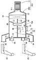
도 2를 참조한다. 공조 장치(10)는 흡입한 공기를 송풍하는 송풍부(11)와, 이 송풍부(11)로부터 송풍된 공기의 온도 조절을 행하여 차실 내에 토출하는 온조부(20)를 갖는다.See Figure 2. The
송풍부(11)에는, 임펠러(11a) 및 도시하지 않은 모터가 수납되어 있다. 모터의 구동에 의해 임펠러(11a)가 회전하고, 차실 내 및/또는 차실 외의 공기가 송풍부(11) 내에 흡입된다. 송풍부(11)에 흡입된 공기는 공기의 흐름 방향을 기준으로 해서 하류측에 배치되어 있는 온조부(20)의 전방부에 공급된다. 이하, 간단히 "상류", "하류"라고 한 경우에는, 공기의 흐름 방향을 기준으로 한다.The
도 2를 참조한다. 온조부(20)는 송풍부(11)(도 1 참조)에 접속되고 내부에 공기의 유로(50)가 형성되어 있는 케이스(40)와, 유로(50) 상에 배치되어 공기를 냉각하는 증발기(23)와, 이 증발기(23)의 하류에 설치되고 증발기(23)를 통과한 공기를 가열하는 히터(24)와, 이 히터(24)를 통과한 공기를 제 1 유로(51)와 제 2 유로(52)로 분류 가능한 구획벽(25)과, 제 1 유로(51)에 설치되고, 이 제 1 유로(51) 내를 흐르는 공기의 온도를 조절하기 위한 제 1 온도 조절 수단(26)과, 제 2 유로(52)에 설치되고, 이 제 2 유로(52) 내를 흐르는 공기의 온도를 조절하기 위한 제 2 온도 조절 수단(27)과, 케이스(40)에 개방되어 있는 케이스 구멍부(41)에 면하여 케이스 구멍부(41)로부터 유출하는 유출 공기를 이용해서 차실(Vi) 내의 공기를 흡인하는 아스피레이터(60)를 구비한다.See Figure 2. The
케이스(40)는, 폴리프로필렌 등의 수지재를 사출 성형해 제조되고, 제 1 유로(51)의 하류에 형성되어 전좌부 시트(S1)에 착석하는 탑승자의 상반신에 송풍하는 제 1 벤트 취출구(42)와, 제 1 유로(51)의 하류에 형성되어 전좌부 시트(S1)에 착석하는 탑승자의 다리에 송풍하는 제 1 풋 취출구(43)와, 제 2 유로(52)의 하류에 형성되어 전우부 시트(S2)에 착석하는 탑승자의 상반신에 송풍하는 제 2 벤트 취출구(44)와, 제 2 유로(52)의 하류에 형성되어 전우부 시트(S2)에 착석하는 탑승자의 다리에 송풍하는 제 2 풋 취출구(45)와, 제 2 유로(52)로부터 자동차 앞유리로 향해 송풍을 행하여 자동차 앞유리의 흐림을 억제하기 위한 디프로스터 취출구(46)와, 제 1 유로(51)의 하류에 형성되어 후좌부 시트(S3)에 착석하는 탑승자에게 송풍하는 제 1 후부 취출구(47)와, 제 2 유로(52)의 하류에 형성되어 후우부 시트(S4)에 착석하는 탑승자에게 송풍하는 제 2 후부 취출구(48)를 구비한다.The
제 1 벤트 취출구(42), 제 1 풋 취출구(43), 및 제 1 후부 취출구(47)는 모두 제 1 유로(51)에 면하고 있는 점에서 공통되어 있다. 이하, 제 1 벤트 취출구(42), 제 1 풋 취출구(43), 및 제 1 후부 취출구(47)를 총칭해서 제 1 취출구(42, 43, 47)라고 부른다.The
제 2 벤트 취출구(44), 제 2 풋 취출구(45), 디프로스터 취출구(46), 및 제 2 후부 취출구(48)는 모두 제 2 유로(52)에 면하고 있는 점에서 공통되어 있다. 이하, 제 2 벤트 취출구(44), 제 2 풋 취출구(45), 디프로스터 취출구(46), 및 제 2 후부 취출구(48)를 총칭해서 제 2 취출구(44 내지 46, 48)라고 부른다.The
또한, 디프로스터 취출구(46)는 제 1 유로(51)에 면하도록 형성하는 것도 가능하다. 이 경우, 디프로스터 취출구(46)는 제 1 취출구에 포함된다.Also, the
제 1 벤트 취출구(42)에 면하는 부위에는, 제 1 벤트 취출구(42)로부터 취출되는 공기의 양을 조정 가능한 제 1 벤트 개폐 도어(32)(제 1 개폐 도어(32))가 설치되어 있다. 제 1 풋 취출구(43)에 면하는 부위에는, 제 1 풋 취출구(43)로부터 취출되는 공기의 양을 조정 가능한 제 1 풋 개폐 도어(33)(제 1 개폐 도어(33))가 설치되어 있다.A first vent opening/closing door 32 (first opening/closing door 32) capable of adjusting the amount of air blown out from the
제 2 벤트 취출구(44)에 면하는 부위에는, 제 2 벤트 취출구(44)로부터 취출되는 공기의 양을 조정 가능한 제 2 벤트 개폐 도어(34)(제 2 개폐 도어(34))가 설치되어 있다. 제 2 풋 취출구(45)에 면하는 부위에는, 제 2 풋 취출구(45)로부터 취출되는 공기의 양을 조정 가능한 제 2 풋 개폐 도어(35)(제 2 개폐 도어(35))가 설치되어 있다. 디프로스터 취출구(46)에 면하는 부위에는, 디프로스터 취출구(46)로부터 취출되는 공기의 양을 조정 가능한 디프로스터 개폐 도어(36)(제 2 개폐 도어(36))가 설치되어 있다.A second vent opening/closing door 34 (second opening/closing door 34) capable of adjusting the amount of air blown out from the
제 1 후부 취출구(47)에 면하는 부위에는, 제 1 후부 취출구(47)로부터 취출되는 공기의 양을 조정 가능한 제 1 후부 개폐 도어(37)(제 1 개폐 도어(37))가 설치되어 있다. 제 2 후부 취출구(48)에 면하는 부위에는, 제 2 후부 취출구(48)로부터 취출되는 공기의 양을 조정 가능한 제 2 후부 개폐 도어(38)(제 2 개폐 도어(38))가 설치되어 있다.A first rear opening/closing door 37 (first opening/closing door 37) capable of adjusting the amount of air blown out from the first
제 1 벤트 개폐 도어(32), 제 1 풋 개폐 도어(33), 및 제 1 후부 개폐 도어(37)는 모두 제 1 취출구(42, 43, 47)에 면하는 개폐 도어인 점에서 공통되어 있다. 이하, 제 1 벤트 개폐 도어(32), 제 1 풋 개폐 도어(33), 및 제 1 후부 개폐 도어(37)를 총칭해서 제 1 개폐 도어(32, 33, 37)라고 부른다.The first vent opening/closing door 32, the first foot opening/closing
제 2 벤트 개폐 도어(34), 제 2 풋 개폐 도어(35), 디프로스터 개폐 도어(36), 및 제 2 후부 개폐 도어(38)는 모두 제 2 취출구(44 내지 46, 48)에 면하는 개폐 도어인 점에서 공통되어 있다. 이하, 제 2 벤트 개폐 도어(34), 제 2 풋 개폐 도어(35), 디프로스터 개폐 도어(36), 및 제 2 후부 개폐 도어(38)를 총칭해서 제 2 개폐 도어(34 내지 36, 38)라고 부른다.The second vent opening and closing
또한, 전술과 같이 디프로스터 취출구(46)는 제 1 유로(51)에 면하도록 형성하는 것도 가능하다. 이 때, 디프로스터 개폐 도어(36)는 제 1 취출구를 개폐하는 제 1 개폐 도어에 포함된다.Also, as described above, the
제 1 후부 취출구(47)로부터 후좌부 시트(S3)로 향해, 후좌부 시트(S3)에 착석하는 탑승자에게 송풍하기 위한 제 1 덕트(D1)가 연장되어 있다. 또한, 제 2 후부 취출구(48)로부터 후우부 시트(S4)로 향해, 후우부 시트(S4)에 착석하는 탑승자에게 송풍하기 위한 제 2 덕트(D2)가 연장되어 있다.A first duct D1 for blowing air to an occupant seated on the rear seat S3 extends from the first
또한, 덕트(D1, D2)의 선단이 면하는 위치는 B 필라나 센터 콘솔의 후단 등 적당 설정할 수 있다. 또한, 덕트(D1, D2)를 추가로 분기시켜, 공조 장치(10)의 운전 모드에 의해 통과하는 부위를 전환할 수도 있다. 또한, 분기시킨 덕트를 각각 다른 위치에 면하게 할 수도 있다.In addition, the position where the tips of the ducts D1 and D2 face can be appropriately set, such as a B-pillar or the rear end of the center console. Further, the ducts D1 and D2 may be further branched, and the passing portion may be switched according to the operation mode of the
케이스(40)는 복수의 수지 성형품이 조합되어 이뤄진다. 케이스(40) 중, 제 1 유로(51)에 면하고 있는 동시에, 구획벽(25)에 대향하고 있는 부위를 대향벽부(40a)라고 부른다.The
케이스(40)의 내부에 형성되어 있는 제 1 유로(51)는 전좌부 시트(S1)에 송풍하기 위한 공기가 흐르는 제 1 앞자리용 유로(51a)와, 이 제 1 앞자리용 유로(51a)로부터 분기해 후좌부 시트(S3)에 송풍하기 위한 공기가 흐르는 제 1 뒷자리용 유로(51b)를 구비한다.The
제 2 유로(52)는 전우부 시트(S2)에 송풍하기 위한 공기가 흐르는 제 2 앞자리용 유로(52a)와, 이 제 2 앞자리용 유로(52a)로부터 분기해 후우부 시트(S4)에 송풍하기 위한 공기가 흐르는 제 2 뒷자리용 유로(52b)를 구비한다.The
케이스(40)의 상면(40b)(도 1 참조)에 형성되어 있는 케이스 구멍부(41)는 대향벽부(40a)보다 구획벽(25)에 가까운 부위에 설치되어 있다. 또한, 케이스 구멍부(41)는 제 1 앞자리용 유로(51a)에 면해서 설치되어 있다.The
증발기(23)는 제 1 유로(51)의 상류측의 단부, 및 제 2 유로(52)의 상류측의 단부를 덮도록 1개 설치되어 있다. 증발기(23)에는, 냉매가 흐르게 되고, 증발기(23)를 통과하는 공기는 냉매와의 열교환에 의해 냉각된다.One
히터(24)는 온수가 흐르게 되는 온수 히터(24a)와, 통전하는 것에 의해 발열하는 전기 히터(24b)로 이뤄진다. 온수 히터(24a), 및 전기 히터(24b)는 모두 구획벽(25)을 관통하도록 해서 설치되고, 제 1 유로(51), 및 제 2 유로(52)의 양쪽 모두에 면하고 있다.The
전기 히터(24b)에는, 통전되는 것으로 고온(예를 들면, 180℃ 정도)으로 되는 발열 소자가 장착되어 있다. 발열 소자는, 전력이 인가되었을 때, 제 1 유로(51)나 제 2 유로(52)의 공기의 통류 상태에 관계없이 발열한다.The
구획벽(25)은 증발기(23)의 후면에 인접하는 부위에서 후방으로 향해 연장되어 있다. 또한, 구획벽(25)의 상류측의 단부와 증발기(23)와의 사이에 간극이 있어도 좋다.The
제 1 온도 조절 수단(26)은 제 1 유로(51) 내에 스윙 가능하게 설치된 외팔보식의 에어 믹스 도어이다. 탑승자가 온도를 설정하면 도시하지 않은 모터가 작동하고, 제 1 온도 조절 수단(26)을 스윙시킨다. 제 1 온도 조절 수단(26)이 스윙하는 것에 의해, 히터(24)로 향하는 공기와 히터(24)를 우회하는 공기의 비율을 조정하고, 이것에 의해 온도를 조정한다. 도면에 도시되는 상태에 있어서, 증발기(23)를 통과한 공기는 모두 히터(24)를 통과한다. 또한, 도시하지 않지만, 제 1 온도 조절 수단(26)은 외팔보식 도어 대신에, 주지의 슬라이드식 도어라도 좋다.The first
제 2 온도 조절 수단(27)도 제 1 온도 조절 수단(26)과 동일하다. 즉, 제 2 온도 조절 수단(27)은 제 2 유로(52) 내에 스윙 가능하게 설치된 외팔보식의 에어 믹스 도어이다. 탑승자가 온도를 설정하면 도시하지 않은 모터가 작동하고, 제 2 온도 조절 수단(27)을 스윙시킨다. 제 2 온도 조절 수단(27)이 스윙하는 것에 의해, 히터(24)로 향하는 공기와 히터(24)를 우회하는 공기의 비율을 조정하고, 이것에 의해 온도를 조정한다. 도면에 도시되는 상태에 있어서, 증발기(23)를 통과한 공기는 모두 히터(24)를 통과한다. 또한, 도시하지 않지만, 제 2 온도 조절 수단(27)은 외팔보식 도어 대신에, 주지의 슬라이드식 도어라도 좋다.The second temperature regulating means (27) is also the same as the first temperature regulating means (26). That is, the second
제 1 벤트 개폐 도어(32)는, 탑승자가 운전 모드를 전환하는 것에 의해, 도시하지 않은 모터가 작동하고, 제 1 벤트 개폐 도어(32)를 회전시킨다. 제 1 벤트 개폐 도어(32)가 회전하는 것에 의해 제 1 벤트 취출구(42)로부터의 공기의 송풍이 허용되고, 또는 규제된다. 도면에 도시되는 상태에 있어서, 제 1 벤트 개폐 도어(32)는 제 1 벤트 취출구(42)를 폐쇄하고 있다. 전좌부 시트(S1)의 운전 모드가 냉방 모드가 되는 것에 의해, 제 1 벤트 개폐 도어(32)는 대략 90° 회전하고, 제 1 벤트 취출구(42)를 개방한다.When the driver switches the driving mode of the first vent opening/closing door 32, a motor (not shown) operates to rotate the first vent opening/closing door 32. When the first vent opening/closing door 32 rotates, blowing of air from the
그 외의 개폐 도어(33 내지 38)에 대해서도, 운전 모드에 의해 소정의 위치로 회전되는 구성으로 되어 있다. 예를 들면, 제 1 풋 개폐 도어(33)는 전좌부 시트(S1)의 운전 모드가 난방 모드가 되는 것에 의해, 제 1 풋 취출구(43)를 개방한다. 또한, 디프로스터 개폐 도어(36)는 자동차 앞유리의 흐림을 제거하기 위한 디프로스터 모드로 되는 것에 의해, 디프로스터 취출구(46)를 개방한다.The other opening/
도면에 도시하는 상태에 있어서, 제 2 풋 취출구(45)와 디프로스터 취출구(46)는 개방되어 있다. 제 1 풋 취출구(43), 제 2 벤트 취출구(44), 제 1 후부 취출구(47), 제 2 후부 취출구(48)는 폐쇄되어 있다.In the state shown in the figure, the
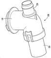
도 1에 도시하는 바와 같이, 아스피레이터(60)는 케이스(40)의 상면(40b)에 설치되어 있다. 도 3 및 도 4를 참조한다. 아스피레이터(60)는 케이스 구멍부(41)에 삽입되고 케이스(40) 내의 공기가 흘러드는 아스피레이터 본체부(61)와, 이 아스피레이터 본체부(61)의 선단으로부터 케이스(40)의 상면(40b)에 따라 연장되고 아스피레이터 본체부(61)를 통과한 공기를 토출하는 디퓨저(62)와, 아스피레이터 본체부(61)에 삽입되어 있는 대략 통형상의 노즐(63)을 구비한다.As shown in FIG. 1 , the
노즐(63)의 말단에는, 튜브(71)의 선단이 접속되어 있고, 이 튜브(71)의 말단은 차실(Vi)에 면하고 있다. 튜브(71)의 내부에는, 차실(Vi) 내의 온도를 검지하기 위한 온도 센서(72)가 설치되어 있다.The tip of the
케이스(40) 내의 공기의 일부는 케이스 구멍부(41)로부터 아스피레이터 본체부(61)로 흐르고, 디퓨저(62)로부터 외부에 유출한다. 이 때, 케이스(40) 내로부터 유출한 유출 공기의 흐름에 의해, 노즐(63)의 선단에 부압이 발생한다. 발생한 부압에 의해 차실(Vi) 내의 공기를 흡인한다. 흡인된 공기는 튜브(71), 및 노즐(63)을 통과하고, 디퓨저(62)로부터 외부로 유출한다. 튜브(71)의 내부에는, 온도 센서(72)가 설치되어 있고, 튜브(71)를 통과하는 공기의 온도로부터 차실(Vi) 내의 온도를 검지할 수 있다.A part of the air in the
온도 센서(72)에 의해 검지된 차실(Vi)의 온도(차실 내 공기의 온도)는 도시하지 않은 제어 장치에 입력되고, 다른 온도 센서나 장치로부터 입력된 물리량과 함께 연산되어, 공조 장치(10)의 온도 제어에 반영된다.The temperature of the cabin Vi detected by the temperature sensor 72 (temperature of the air inside the cabin) is input to a control device (not shown), calculated together with a physical quantity input from another temperature sensor or device, and the air conditioner 10 ) is reflected in the temperature control of
이상으로 설명한 공조 장치(10)는 이하의 효과를 이룬다.The
도 2 및 도 4를 참조한다. 송풍부(11)에 의해 유로(50)에 송풍된 공기는 증발기(23)를 통과하고, 제 1 유로(51)와 제 2 유로(52)에 유입한다. 난방 모드 시에, 온수 히터(24a)에는 온수가 통류되고, 전기 히터(24b)에는 전력이 인가된다. 그리고, 제 1 개폐 도어(32, 33, 37)에 의해 제 1 취출구(42, 43, 47)가 폐색되고, 제 2 개폐 도어(34 내지 36, 38)에 의해 제 2 취출구(44 내지 46, 48) 중 어느 한쪽이 해방되는 취출 모드가 선택되어 있을 때, 제 2 유로(52)에 유입한 공기는 히터(24)(온수 히터(24a)와 전기 히터(24b))에 의해 가열되어 온풍이 되고, 제 2 취출구(44 내지 46, 48) 중 어느 하나로부터 차실(Vi)로 취출된다. 또한, 제 1 유로(51)에 유입한 공기는 히터(24)(온수 히터(24a)와 전기 히터(24b))에 의해 가열되어 온풍으로 되지만, 제 1 취출구(42, 43, 47)로부터 차실(Vi)에 취출되는 것이 저지되어, 제 1 유로(51)에 가득찬다. 특히, 제 1 유로(51)에 가득찬 공기는 전기 히터(24b)의 발열 소자에 의해 과잉으로 가열될 우려가 있다.See Figures 2 and 4. The air blown to the
그러나, 이 실시예에서는, 제 1 유로(51)에 면하는 부위에 설치된 케이스 구멍부(41) 및 아스피레이터(60)를 거쳐서 제 1 유로(51)의 공기가 차실(Vi) 내에 유출하는 것으로, 히터(24) 주연의 열이 제 1 유로(51)에 체류하는 것을 억제할 수 있다. 열이 가득차는 것에 의해 생기는 케이스(40) 등에의 열에 의한 영향을 경감할 수 있고, 제품 수명이 긴 공조 장치(10)를 제공할 수 있다.However, in this embodiment, the air of the
고온의 공기는 주위의 공기보다 상대 질량이 낮게 상승하면, 제 1 유로(51)의 상방에 집합하는 경향이 있다. 여기서, 케이스(40)의 상면(40b)에 케이스 구멍부(41)가 형성되는 것에 의해, 특히 고온의 공기를 외부에 방출하기 쉬워진다. 효율적으로 열의 체류를 억제할 수 있다.When the high-temperature air rises to a lower relative mass than the surrounding air, it tends to collect above the
그런데, 차실(Vi)의 공기의 온도는 제 2 유로(52)를 통과하는 가열된 공기의 온도보다 낮다. 제 1 유로(51)에 체류한 고온의 공기가 케이스(40)에 전열할 때, 대향벽부(40a)를 거쳐서 차실(Vi)의 공기에 방열하는 열량이 구획벽(25)을 거쳐서 제 2 유로(52)의 공기에 방열하는 열량보다 많다. 이 때문에, 제 1 유로(51)에 체류한 고온의 공기는 장소에 의해 온도에 불균형이 발생하고, 구획벽(25) 근방의 공기의 온도가 대향벽부(40a) 근방의 공기보다 상대적으로 고온으로 된다. 여기서, 케이스 구멍부(41)를 대향벽부(40a)보다 구획벽(25)에 가까운 위치에 마련하는 것으로, 보다 고온의 공기를 방출할 수 있고, 효율적으로 열의 체류를 억제할 수 있다.However, the temperature of the air in the compartment Vi is lower than the temperature of the heated air passing through the
또한, 공조 장치(10)는 공기의 취출량에 대해서, 일반적으로 후좌부 시트(S3)보다 전좌부 시트(S1)의 쪽에 많이 취출하도록 설정되고, 제 1 앞자리용 유로(51a)의 쪽이 제 1 뒷자리용 유로(51b)보다 공간 용적도 크다. 케이스 구멍부(41)를 제 1 앞자리용 유로(51a)에 면하도록 마련하는 것으로, 큰 용적의 공간에 고온의 공기가 체류하는 것을 방지하고, 공조 장치 전체적으로 열의 체류를 효과적으로 억제할 수 있다.In addition, the
또한, 디프로스터 취출구(46)는 제 2 유로(52)에만 형성되어 있다. 즉, 제 1 유로(51)에 아스피레이터(60)가 면하고, 제 2 유로(52)에 디프로스터 취출구(46)가 형성되어 있다. 한쪽의 유로에 아스피레이터(60)가 면하고, 다른쪽의 유로에 디프로스터 취출구(46)가 면하는 것에 의해, 어느 한쪽의 유로에만 열이 가득차는 것을 억제할 수 있다.In addition, the
<실시예 2><Example 2>
다음에, 실시예 2에 의한 공조 장치(10A)를 도면에 근거해 설명한다.Next, the
도 5에는, 실시예 2에 의한 공조 장치(10A)가 모식적으로 도시되어 있다. 실시예 2에 의한 공조 장치(10A)의 온조부(20A)는 아스피레이터(60)가 면하고 있는 제 1 유로(51)가 우측에 배치되고, 제 2 유로(52)가 좌측에 배치되어 있다. 또한, 공조 장치(10A)는 뒷좌석에의 취출구를 갖지 않는다. 또한, 디프로스터 취출구(49)(제 1 취출구(49)), 및 디프로스터 개폐 도어(39)(제 1 개폐 도어(39))는 제 1 유로(51)에 설치되어 있다. 또한, 히터(84)는 온수 히터만으로 구성되며, 전기 히터를 갖지 않는다.5 schematically shows an
그 외의 기본적인 구성에 대해서는, 실시예 1에 의한 공조 장치(10)(도 2 참조)와 공통된다. 실시예 1과 공통되는 부분에 대해서는, 부호를 유용함과 동시에, 상세한 설명을 생략한다.Other basic configurations are the same as those of the
이상으로 설명한 공조 장치(10A)도 본 발명 소정의 효과를 이룬다.The
또한, 본 발명에 의한 공조 장치는 각 실시예에 나타낸 것으로 한정되는 것은 아니다. 예를 들면, 각 실시예를 조합하는 것도 가능하다. 도 2에 나타낸 공조 장치의 히터를 온수식의 히터만에 의해 구성하는 것이나, 도 5에 도시한 공조 장치에 뒷자리에의 취출구를 마련하는 것도 가능하다.In addition, the air conditioner according to the present invention is not limited to those shown in each embodiment. For example, it is also possible to combine each embodiment. It is also possible to configure the heater of the air conditioner shown in FIG. 2 with only a hot water heater, or to provide an air outlet to the back seat of the air conditioner shown in FIG. 5 .
본 발명의 작용 및 효과를 이루는 한에 있어서, 본 발명은 실시예로 한정되는 것은 아니다.Insofar as the actions and effects of the present invention are achieved, the present invention is not limited to the Examples.
본 발명의 공조 장치는 승용 차량에 탑재하는데 매우 적합하다.The air conditioner of the present invention is very suitable for mounting in a passenger vehicle.
10, 10A: 차량용 공조 장치
23: 증발기
24, 84: 히터
25: 구획벽
26: 제 1 온도 조절 수단
27: 제 2 온도 조절 수단
32: 제 1 벤트 개폐 도어(제 1 개폐 도어)
33: 제 1 풋 개폐 도어(제 1 개폐 도어)
37: 제 1 후부 개폐 도어(제 1 개폐 도어)
39: 디프로스터 개폐 도어(제 1 개폐 도어)
40: 케이스
40a: 대향벽부
40b: 상면
41: 케이스 구멍부
42: 제 1 벤트 취출구(제 1 취출구)
43: 제 1 풋 취출구(제 1 취출구)
44: 제 2 벤트 취출구(제 2 취출구)
45: 제 2 풋 취출구(제 2 취출구)
46: 디프로스터 취출구(제 2 취출구)
47: 제 1 후부 취출구(제 1 취출구)
48: 제 2 후부 취출구(제 2 취출구)
49: 디프로스터 취출구(제 1 취출구)
50: 유로
51: 제 1 유로
51a: 제 1 앞자리용 유로
51b: 제 1 뒷자리용 유로
52: 제 2 유로
60: 아스피레이터
Vi: 차실
S1: 전좌부 시트(앞자리)
S3: 후좌부 시트(뒷자리)10, 10A: Vehicle air conditioner
23: evaporator
24, 84: heater
25: partition wall
26: first temperature control means
27: second temperature control means
32: first vent opening and closing door (first opening and closing door)
33: first foot opening and closing door (first opening and closing door)
37: first rear opening and closing door (first opening and closing door)
39: defroster opening and closing door (first opening and closing door)
40: case
40a: opposite wall portion
40b: upper surface
41: case hole
42: first vent outlet (first outlet)
43: first foot outlet (first outlet)
44: second vent outlet (second outlet)
45: 2nd foot outlet (2nd outlet)
46: defroster outlet (second outlet)
47: first rear air outlet (first air outlet)
48: second rear air outlet (second air outlet)
49: defroster outlet (first outlet)
50: Euro
51: 1st euro
51a: passage for the first front seat
51b: passage for the first rear seat
52: second euro
60: Aspirator
Vi: tea room
S1: front seat (front seat)
S3: Rear seat (rear seat)
Claims (4)
내부에 공기의 유로(50)가 형성되어 있는 케이스(40)와,
상기 유로(50)에 배치되어 공기를 냉각하는 증발기(23)와,
상기 증발기(23)를 통과한 공기를 가열하는 히터(24; 84)와,
상기 유로(50)를 구획하여 상기 히터(24; 84)를 통과한 공기를 제 1 유로(51)와 제 2 유로(52)로 분류 가능한 구획벽(25)과,
상기 제 1 유로(51)에 설치되고, 이 제 1 유로(51) 내를 흐르는 공기의 온도를 조절하기 위한 제 1 온도 조절 수단(26)과,
상기 제 2 유로(52)에 설치되고, 이 제 2 유로(52) 내를 흐르는 공기의 온도를 조절하기 위한 제 2 온도 조절 수단(27)과,
상기 케이스(40)에 형성되어 상기 제 1 유로(51)를 흐른 공기를 취출하는 제 1 취출구(42, 43, 47; 49)와,
상기 제 1 취출구(42, 43, 47; 49)로부터 취출되는 공기의 양을 조정 가능한 제 1 개폐 도어(32, 33, 37; 39)와,
상기 케이스(40)에 형성되어 상기 제 2 유로(52)를 흐른 공기를 취출하는 제 2 취출구(44 내지 46, 48)와,
상기 제 2 취출구(44 내지 46, 48)로부터 취출되는 공기의 양을 조정 가능한 제 2 개폐 도어(34 내지 36, 38)를 구비하며,
상기 제 1 개폐 도어(32, 33, 37; 39)는 상기 제 1 취출구(42, 43, 47; 49)를 폐색 가능하고,
상기 케이스(40)에는, 상기 제 1 유로(51)에 면하는 부위에 케이스 구멍부(41)가 설치되며,
이 케이스 구멍부(41)에는, 당해 케이스 구멍부(41)로부터 유출하는 유출 공기를 이용해서 차실 내의 공기를 흡인하는 것과 동시에 상기 유출 공기와 흡인된 차실 내의 공기를 유출하는 아스피레이터(60)가 설치되어 있는
차량용 공조 장치.In a vehicle air conditioner (10; 10A) disposed in a vehicle cabin,
A case 40 having an air flow path 50 formed therein;
An evaporator 23 disposed in the flow path 50 to cool air;
A heater (24; 84) for heating the air passing through the evaporator (23);
A partition wall (25) capable of partitioning the flow path (50) and dividing the air passing through the heater (24; 84) into a first flow path (51) and a second flow path (52);
a first temperature control unit (26) installed in the first flow path (51) and regulating the temperature of the air flowing through the first flow path (51);
a second temperature control means (27) installed in the second flow path (52) and regulating the temperature of the air flowing through the second flow path (52);
A first air outlet (42, 43, 47; 49) formed in the case (40) to discharge air flowing through the first flow path (51);
A first opening and closing door (32, 33, 37; 39) capable of adjusting the amount of air blown out from the first air outlet (42, 43, 47; 49);
second air outlets 44 to 46 and 48 formed in the case 40 and discharging air flowing through the second flow path 52;
And a second opening and closing door (34 to 36, 38) capable of adjusting the amount of air blown out from the second outlet (44 to 46, 48),
The first opening/closing door (32, 33, 37; 39) can block the first outlet (42, 43, 47; 49),
In the case 40, a case hole 41 is installed at a portion facing the first flow path 51,
In this case hole portion 41, an aspirator 60 that sucks in the air in the cabin using outflow air flowing out from the case hole portion 41 and simultaneously flows out the outflow air and the sucked air in the cabin. is installed
Vehicle air conditioner.
상기 케이스 구멍부(41)는 상기 케이스(40)의 상면(40b)에 설치되어 있는
차량용 공조 장치.According to claim 1,
The case hole 41 is installed on the upper surface 40b of the case 40
Vehicle air conditioner.
상기 케이스(40) 중, 상기 구획벽(25)에 대향하고 있는 부위를 대향벽부(40a)로 한 경우에, 상기 케이스 구멍부(41)는 상기 대향벽부(40a)보다 상기 구획벽(25)에 가까운 부위에 설치되어 있는
차량용 공조 장치.According to claim 1 or 2,
When the portion of the case 40 facing the partition wall 25 is the opposing wall portion 40a, the case hole portion 41 is larger than the opposing wall portion 40a to the partition wall 25. installed in close proximity to
Vehicle air conditioner.
상기 제 1 유로(51)는 차실(Vi)의 앞자리(S1)에 송풍하기 위한 공기가 흐르는 제 1 앞자리용 유로(51a)와, 차실(Vi)의 뒷자리(S3)에 송풍하기 위한 공기가 흐르는 제 1 뒷자리용 유로(51b)를 구비하며,
상기 케이스 구멍부(41)는 상기 제 1 앞자리용 유로(51a)에 면해서 설치되어 있는
차량용 공조 장치.According to any one of claims 1 to 3,
The first flow path 51 includes a first flow path 51a through which air for blowing air to the front seat S1 of the cabin Vi flows, and air for blowing air to the back seat S3 of the cabin Vi. A first flow path 51b for the back seat is provided,
The case hole portion 41 is provided facing the first flow path 51a for the front seat.
Vehicle air conditioner.
Applications Claiming Priority (3)
| Application Number | Priority Date | Filing Date | Title |
|---|---|---|---|
| JPJP-P-2021-020005 | 2021-02-10 | ||
| JP2021020005 | 2021-02-10 | ||
| PCT/JP2022/004178 WO2022172844A1 (en) | 2021-02-10 | 2022-02-03 | Vehicle air conditioning device |
Publications (1)
| Publication Number | Publication Date |
|---|---|
| KR20230006510A true KR20230006510A (en) | 2023-01-10 |
Family
ID=82837801
Family Applications (1)
| Application Number | Title | Priority Date | Filing Date |
|---|---|---|---|
| KR1020227040384A KR20230006510A (en) | 2021-02-10 | 2022-02-03 | car air conditioner |
Country Status (4)
| Country | Link |
|---|---|
| JP (1) | JPWO2022172844A1 (en) |
| KR (1) | KR20230006510A (en) |
| CN (1) | CN116848002A (en) |
| WO (1) | WO2022172844A1 (en) |
Citations (1)
| Publication number | Priority date | Publication date | Assignee | Title |
|---|---|---|---|---|
| JP2008296717A (en) | 2007-05-31 | 2008-12-11 | Denso Corp | Air-conditioner for vehicle |
Family Cites Families (3)
| Publication number | Priority date | Publication date | Assignee | Title |
|---|---|---|---|---|
| JPH0474114U (en) * | 1990-11-08 | 1992-06-29 | ||
| JPH11180128A (en) * | 1997-12-18 | 1999-07-06 | Denso Corp | Air conditioner for vehicle |
| JP6123557B2 (en) * | 2013-08-06 | 2017-05-10 | 株式会社デンソー | Air conditioner for vehicles |
-
2022
- 2022-02-03 KR KR1020227040384A patent/KR20230006510A/en unknown
- 2022-02-03 WO PCT/JP2022/004178 patent/WO2022172844A1/en active Application Filing
- 2022-02-03 JP JP2022580590A patent/JPWO2022172844A1/ja active Pending
- 2022-02-03 CN CN202280013177.8A patent/CN116848002A/en active Pending
Patent Citations (1)
| Publication number | Priority date | Publication date | Assignee | Title |
|---|---|---|---|---|
| JP2008296717A (en) | 2007-05-31 | 2008-12-11 | Denso Corp | Air-conditioner for vehicle |
Also Published As
| Publication number | Publication date |
|---|---|
| JPWO2022172844A1 (en) | 2022-08-18 |
| CN116848002A (en) | 2023-10-03 |
| WO2022172844A1 (en) | 2022-08-18 |
Similar Documents
| Publication | Publication Date | Title |
|---|---|---|
| EP1564047B1 (en) | Automotive air-conditioning system | |
| US20120129439A1 (en) | Air conditioning system for vehicle | |
| JP6370083B2 (en) | Air conditioner for vehicles | |
| JP2007137189A (en) | Air conditioner for automobile | |
| US20110005734A1 (en) | Vehicular air conditioning apparatus | |
| WO2006114909A1 (en) | Air conditioner for vehicle | |
| KR101113669B1 (en) | Air-conditioner for vehicle | |
| US8689860B2 (en) | Vehicular air conditioning apparatus | |
| KR20180029128A (en) | Air conditioner for vehicle | |
| JP4935515B2 (en) | Air conditioner for vehicles | |
| JP7321016B2 (en) | vehicle air conditioner | |
| JP2006240539A (en) | Air conditioner for vehicle | |
| KR20230006510A (en) | car air conditioner | |
| KR20230006511A (en) | car air conditioner | |
| JP4032987B2 (en) | In-vehicle air conditioner | |
| JP2012106667A (en) | Vehicle air conditioner | |
| KR101425078B1 (en) | Ventilation system for car backseat | |
| KR101238229B1 (en) | Rear air conditioner for vehicles | |
| KR20210008401A (en) | A housing to be mounted on an automobile door, and a door comprising such a housing | |
| WO2020230562A1 (en) | Air-blowing unit | |
| JP3877187B2 (en) | Air conditioner for automobile | |
| KR101094844B1 (en) | Air conditioning case for vehicle | |
| JP2009120079A (en) | Vehicular seat air conditioner | |
| KR102162835B1 (en) | Air conditioning system for a vehicle | |
| KR102104529B1 (en) | Air conditioner for vehicle |