KR20220167006A - Frost removing for Fan - Google Patents
Frost removing for Fan Download PDFInfo
- Publication number
- KR20220167006A KR20220167006A KR1020210076000A KR20210076000A KR20220167006A KR 20220167006 A KR20220167006 A KR 20220167006A KR 1020210076000 A KR1020210076000 A KR 1020210076000A KR 20210076000 A KR20210076000 A KR 20210076000A KR 20220167006 A KR20220167006 A KR 20220167006A
- Authority
- KR
- South Korea
- Prior art keywords
- gear
- motor
- fan
- gear shaft
- crank
- Prior art date
- Legal status (The legal status is an assumption and is not a legal conclusion. Google has not performed a legal analysis and makes no representation as to the accuracy of the status listed.)
- Granted
Links
Images








Classifications
-
- F—MECHANICAL ENGINEERING; LIGHTING; HEATING; WEAPONS; BLASTING
- F04—POSITIVE - DISPLACEMENT MACHINES FOR LIQUIDS; PUMPS FOR LIQUIDS OR ELASTIC FLUIDS
- F04D—NON-POSITIVE-DISPLACEMENT PUMPS
- F04D25/00—Pumping installations or systems
- F04D25/02—Units comprising pumps and their driving means
- F04D25/08—Units comprising pumps and their driving means the working fluid being air, e.g. for ventilation
-
- A—HUMAN NECESSITIES
- A01—AGRICULTURE; FORESTRY; ANIMAL HUSBANDRY; HUNTING; TRAPPING; FISHING
- A01G—HORTICULTURE; CULTIVATION OF VEGETABLES, FLOWERS, RICE, FRUIT, VINES, HOPS OR SEAWEED; FORESTRY; WATERING
- A01G13/00—Protection of plants
- A01G13/06—Devices for generating heat, smoke or fog in gardens, orchards or forests, e.g. to prevent damage by frost
- A01G13/065—Frost protection by generating fog or by spraying
-
- A—HUMAN NECESSITIES
- A01—AGRICULTURE; FORESTRY; ANIMAL HUSBANDRY; HUNTING; TRAPPING; FISHING
- A01G—HORTICULTURE; CULTIVATION OF VEGETABLES, FLOWERS, RICE, FRUIT, VINES, HOPS OR SEAWEED; FORESTRY; WATERING
- A01G13/00—Protection of plants
- A01G13/08—Mechanical apparatus for circulating the air
-
- F—MECHANICAL ENGINEERING; LIGHTING; HEATING; WEAPONS; BLASTING
- F04—POSITIVE - DISPLACEMENT MACHINES FOR LIQUIDS; PUMPS FOR LIQUIDS OR ELASTIC FLUIDS
- F04D—NON-POSITIVE-DISPLACEMENT PUMPS
- F04D25/00—Pumping installations or systems
- F04D25/02—Units comprising pumps and their driving means
- F04D25/028—Units comprising pumps and their driving means the driving means being a planetary gear
-
- F—MECHANICAL ENGINEERING; LIGHTING; HEATING; WEAPONS; BLASTING
- F04—POSITIVE - DISPLACEMENT MACHINES FOR LIQUIDS; PUMPS FOR LIQUIDS OR ELASTIC FLUIDS
- F04D—NON-POSITIVE-DISPLACEMENT PUMPS
- F04D25/00—Pumping installations or systems
- F04D25/02—Units comprising pumps and their driving means
- F04D25/06—Units comprising pumps and their driving means the pump being electrically driven
-
- F—MECHANICAL ENGINEERING; LIGHTING; HEATING; WEAPONS; BLASTING
- F04—POSITIVE - DISPLACEMENT MACHINES FOR LIQUIDS; PUMPS FOR LIQUIDS OR ELASTIC FLUIDS
- F04D—NON-POSITIVE-DISPLACEMENT PUMPS
- F04D29/00—Details, component parts, or accessories
- F04D29/26—Rotors specially for elastic fluids
- F04D29/32—Rotors specially for elastic fluids for axial flow pumps
- F04D29/325—Rotors specially for elastic fluids for axial flow pumps for axial flow fans
-
- F—MECHANICAL ENGINEERING; LIGHTING; HEATING; WEAPONS; BLASTING
- F04—POSITIVE - DISPLACEMENT MACHINES FOR LIQUIDS; PUMPS FOR LIQUIDS OR ELASTIC FLUIDS
- F04D—NON-POSITIVE-DISPLACEMENT PUMPS
- F04D29/00—Details, component parts, or accessories
- F04D29/60—Mounting; Assembling; Disassembling
- F04D29/64—Mounting; Assembling; Disassembling of axial pumps
- F04D29/644—Mounting; Assembling; Disassembling of axial pumps especially adapted for elastic fluid pumps
- F04D29/646—Mounting or removal of fans
-
- F—MECHANICAL ENGINEERING; LIGHTING; HEATING; WEAPONS; BLASTING
- F05—INDEXING SCHEMES RELATING TO ENGINES OR PUMPS IN VARIOUS SUBCLASSES OF CLASSES F01-F04
- F05D—INDEXING SCHEME FOR ASPECTS RELATING TO NON-POSITIVE-DISPLACEMENT MACHINES OR ENGINES, GAS-TURBINES OR JET-PROPULSION PLANTS
- F05D2210/00—Working fluids
- F05D2210/10—Kind or type
- F05D2210/12—Kind or type gaseous, i.e. compressible
-
- F—MECHANICAL ENGINEERING; LIGHTING; HEATING; WEAPONS; BLASTING
- F05—INDEXING SCHEMES RELATING TO ENGINES OR PUMPS IN VARIOUS SUBCLASSES OF CLASSES F01-F04
- F05D—INDEXING SCHEME FOR ASPECTS RELATING TO NON-POSITIVE-DISPLACEMENT MACHINES OR ENGINES, GAS-TURBINES OR JET-PROPULSION PLANTS
- F05D2260/00—Function
- F05D2260/30—Retaining components in desired mutual position
Landscapes
- Engineering & Computer Science (AREA)
- Mechanical Engineering (AREA)
- General Engineering & Computer Science (AREA)
- Life Sciences & Earth Sciences (AREA)
- Health & Medical Sciences (AREA)
- General Health & Medical Sciences (AREA)
- Toxicology (AREA)
- Environmental Sciences (AREA)
- Forests & Forestry (AREA)
- Structures Of Non-Positive Displacement Pumps (AREA)
- Connection Of Motors, Electrical Generators, Mechanical Devices, And The Like (AREA)
Abstract
Description
본 발명은, 방재팬에 관한 것으로서, 더욱 상세하게는, 기어에 가해지는 힘을 분산시켜 부품의 손상 없이 제품의 내구성을 높일 수 있으며, 종래보다 회전 각도를 줄여서 전선의 꼬임을 방지할 수 있는 방재팬에 관한 것이다.The present invention relates to a disaster prevention fan, and more particularly, to a method capable of dispersing the force applied to a gear to increase the durability of a product without damaging parts and preventing twisting of wires by reducing the rotation angle compared to the prior art. It's about Japan.
방재팬은 특별한 용도에 맞게 사용되는 대형 선풍기의 일종이다. 예컨대, 방재팬은 골프장 등에서 이슬 등이 맺히는 걸 방지하기 위해 회전하면서 바람을 송풍할 수 있다. 이러한 방재팬에 관한 기술이 대한민국특허청 출원번호 제10-2011-0052219호 등에 공지되어 있다.Disaster fan is a type of large electric fan used for special purposes. For example, the disaster prevention fan may blow wind while rotating to prevent dew from forming on a golf course or the like. A technology related to such a disaster fan is known in the Republic of Korea Intellectual Property Office Application No. 10-2011-0052219 and the like.
한편, 현존하는 방재팬의 경우, 단순한 기어 방식, 예컨대 팬모터가 메인 기어를 직접 회전시키고 메인 기어와 기어 맞물림된 서브 기어가 회전하는 구조로 방재팬이 회전하는 단순 방식이라서 기어에 무리한 힘이 가해질 수 있으며, 이로 인해 결과적으로 방재팬 제품이 손상될 우려가 큰 문제점이 있다.On the other hand, in the case of the existing disaster prevention fan, a simple gear method, for example, a fan motor directly rotates the main gear and a structure in which a sub gear meshed with the main gear rotates, so that excessive force may be applied to the gear. It can be, and as a result, there is a great concern that the disaster Japan product will be damaged.
그뿐만 아니라 종래기술의 경우에는 그 구조적인 한계로 인해 팬이 360도 회전할 때, 팬모터에 연결되는 전선이 꼬일 수 있다는 점을 두루 고려해볼 때, 이러한 문제점을 해결하기 위한 새로운 개념의 방재팬에 관한 필요성이 대두된다.In addition, in the case of the prior art, considering the fact that the wire connected to the fan motor may be twisted when the fan rotates 360 degrees due to its structural limitations, a new concept of disaster prevention fan to solve this problem The need for is emerging.
본 발명의 목적은, 기어에 가해지는 힘을 분산시켜 부품의 손상 없이 제품의 내구성을 높일 수 있으며, 종래보다 회전 각도를 줄여서 전선의 꼬임을 방지할 수 있는 방재팬을 제공하는 것이다.An object of the present invention is to provide a disaster prevention fan capable of dispersing the force applied to the gear to increase the durability of the product without damaging the parts and preventing twisting of the electric wire by reducing the rotation angle compared to the prior art.
상기 목적은, 복수 개의 블레이드가 보스(boss)를 통해 회전 가능하게 연결되는 팬모터; 상기 팬모터와 연결되고 상기 팬모터를 지지하는 모터 베이스(motor base); 및 상기 모터 베이스에 이웃하게 배치되며, 상기 모터 베이스를 통해 상기 팬모터를 회전시키는 팬모터 회전유닛을 포함하며, 상기 팬모터 회전유닛은, 상기 팬모터를 회전시키기 위한 동력을 발생시키는 기어드 모터(geard motor); 외관을 형성하는 유닛 커버; 상기 유닛 커버와의 사이에 부품탑재공간이 형성되게 상기 유닛 커버의 일측에 결합하며, 상기 기어드 모터가 결합하는 커버 베이스; 상기 부품탑재공간에 마련되며, 상기 기어드 모터의 모터 샤프트가 결합하는 제1 기어 샤프트홀을 구비하는 제1 기어; 상기 부품탑재공간에서 상기 제1 기어와 외접하되 기어비 조정을 위해 상기 제1 기어보다는 지름이 크게 형성되며, 센터(center)의 제2 기어 샤프트홀에서 일측으로 편심된 위치에 제1 크랭크 결합부가 형성되는 제2 기어; 상기 부품탑재공간에서 상기 제2 기어에 이웃하게 이격 배치되며, 센터(center)의 제3 기어 샤프트홀에서 일측으로 편심된 위치에 제2 크랭크 결합부가 형성되는 제3 기어; 상기 부품탑재공간에 마련되되 상기 제2 및 제3 기어와 외접하며, 센터 영역에 제4 기어 샤프트홀이 형성되는 제4 기어; 및 양단부가 상기 제2 기어의 제1 크랭크 결합부와 상기 제3 기어의 제2 크랭크 결합부에 각각 결합하는 크랭크(crank)를 포함하는 것을 특징으로 하는 방재팬에 의해 달성된다.The above object is a fan motor in which a plurality of blades are rotatably connected through a boss; a motor base connected to the fan motor and supporting the fan motor; and a fan motor rotation unit disposed adjacent to the motor base and rotating the fan motor through the motor base, wherein the fan motor rotation unit includes a geared motor generating power for rotating the fan motor ( geared motor); a unit cover forming an exterior; a cover base coupled to one side of the unit cover to form a component mounting space between the unit cover and to which the geared motor is coupled; a first gear provided in the component mounting space and having a first gear shaft hole coupled to a motor shaft of the geared motor; It externally contacts the first gear in the component mounting space, but has a larger diameter than the first gear to adjust the gear ratio, and the first crank coupling part is formed at a position eccentric to one side in the second gear shaft hole of the center. a second gear; a third gear disposed adjacent to and spaced apart from the second gear in the component mounting space, and having a second crank coupling part formed at a position eccentric to one side in the third gear shaft hole of the center; a fourth gear provided in the component mounting space, externally contacting the second and third gears, and having a fourth gear shaft hole formed in a center region; And both ends are achieved by a disaster prevention fan characterized in that it comprises a crank (crank) coupled to the first crank coupling portion of the second gear and the second crank coupling portion of the third gear, respectively.
상기 크랭크의 양단부와 상기 제1 크랭크 결합부 및 상기 제2 크랭크 결합부 사이에 결합하는 복수 개의 크랭크 샤프트(crank shaft)를 더 포함할 수 있다.A plurality of crank shafts coupled between both ends of the crank and the first crank coupling part and the second crank coupling part may be further included.
상기 제2 기어의 제2 기어 샤프트홀에 연결되는 제2 기어 샤프트; 상기 제3 기어의 제3 기어 샤프트홀에 연결되는 제3 기어 샤프트; 일단부가 상기 제4 기어의 제4 기어 샤프트홀에 연결되고 상기 제4 기어와 동회전하는 제4 기어 샤프트; 및 일측은 상기 제4 기어 샤프트의 타단부에 연결되고 타측은 상기 모터 베이스에 결합하며, 상기 제4 기어 샤프트의 회전운동을 상기 모터 베이스로 전달하는 제4 기어 샤프트 브래킷을 더 포함할 수 있다.a second gear shaft connected to the second gear shaft hole of the second gear; a third gear shaft connected to the third gear shaft hole of the third gear; a fourth gear shaft having one end connected to a fourth gear shaft hole of the fourth gear and co-rotating with the fourth gear; and a fourth gear shaft bracket having one side connected to the other end of the fourth gear shaft and the other side coupled to the motor base, and transmitting rotational motion of the fourth gear shaft to the motor base.
상기 제4 기어 샤프트 브래킷에는 그 둘레면에 상기 모터 베이스에 결합하기 위한 복수 개의 베이스 결합홀이 형성되고, 상기 베이스 결합홀들의 반경 방향 내측에 상기 제4 기어 샤프트와 결합하기 위한 복수 개의 샤프트 결합홀이 형성될 수 있다.A plurality of base coupling holes for coupling to the motor base are formed on a circumferential surface of the fourth gear shaft bracket, and a plurality of shaft coupling holes for coupling with the fourth gear shaft are formed radially inside the base coupling holes. can be formed.
상기 유닛 커버와 상기 커버 베이스 사이에 방수 러버(waterproof rubber)가 개재되며, 상기 커버 베이스에 포스트(post)가 연결될 수 있다.A waterproof rubber may be interposed between the unit cover and the cover base, and a post may be connected to the cover base.
상기 모터 베이스는, 상기 팬모터와 연결되는 모터 베이스 탑(motor base top); 및 일측은 상기 모터 베이스 탑과 연결되고 타측은 상기 팬모터 회전유닛과 연결되는 모터 베이스 바텀(motor base bottom)을 포함할 수 있다.The motor base may include a motor base top connected to the fan motor; and a motor base bottom having one side connected to the motor base top and the other side connected to the fan motor rotation unit.
본 발명에 따르면, 기어에 가해지는 힘을 분산시켜 부품의 손상 없이 제품의 내구성을 높일 수 있으며, 종래보다 회전 각도를 줄여서 전선의 꼬임을 방지할 수 있는 효과가 있다.According to the present invention, the durability of the product can be increased without damaging the parts by dispersing the force applied to the gear, and the twisting of the wire can be prevented by reducing the rotation angle compared to the prior art.
도 1은 본 발명의 일 실시예에 따른 방재팬의 사시도이다.
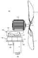
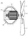
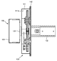
도 2 및 도 3은 각각 도 1의 정면도 및 평면도이다.
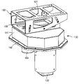
도 4는 도 1에서 팬모터를 제거한 도면이다.
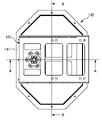
도 5는 도 4의 평면도이다.
도 6 및 도 7은 각각 도 5의 A-A선 및 B-B선에 따른 단면도이다.
도 8은 도 1의 분해 사시도이다.
도 9 및 도 10은 도 8의 요부 구성을 확대한 도면들이다.
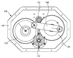
도 11은 제1 내지 제4 기어의 배치 관계 사시도이다.
도 12는 도 11의 평면도이다.
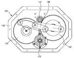
도 13a 내지 도 13k는 팬모터 회전유닛의 동작도들이다.1 is a perspective view of a disaster Japan according to an embodiment of the present invention.
2 and 3 are a front view and a plan view of FIG. 1, respectively.
FIG. 4 is a view in which the fan motor is removed from FIG. 1 .
FIG. 5 is a plan view of FIG. 4 .
6 and 7 are cross-sectional views taken along lines AA and BB of FIG. 5 , respectively.
8 is an exploded perspective view of FIG. 1;
9 and 10 are enlarged views of main parts of FIG. 8 .
11 is a perspective view of the arrangement of first to fourth gears.
Fig. 12 is a plan view of Fig. 11;
13A to 13K are operation diagrams of the fan motor rotation unit.
아래에서는 첨부한 도면을 참고로 하여 본 발명의 실시예에 대하여 본 발명이 속하는 기술분야에서 통상의 지식을 가진 자가 쉽게 실시할 수 있도록 상세히 설명한다.Hereinafter, with reference to the accompanying drawings, embodiments of the present invention will be described in detail so that those skilled in the art can easily carry out the present invention.
한편, 하기 본 발명에 관한 설명은 구조적이나 기능적 설명을 위한 실시예에 불과하다. 따라서 본 발명의 권리범위는 본문에 설명된 실시예에 의하여 제한되는 것으로 해석되어서는 아니 된다.On the other hand, the following description of the present invention is only an embodiment for structural or functional description. Therefore, the scope of the present invention should not be construed as being limited by the embodiments described in the text.
예컨대, 실시예는 다양한 변경이 가능하고 여러 가지 형태를 가질 수 있으므로 본 발명의 권리범위는 기술적 사상을 실현할 수 있는 균등물들을 포함하는 것으로 이해되어야 한다.For example, since the embodiment can be changed in various ways and can have various forms, it should be understood that the scope of the present invention includes equivalents capable of realizing the technical idea.
또한, 본 발명에서 제시된 목적 또는 효과는 특정 실시예가 이를 전부 포함하여야 한다거나 그러한 효과만을 포함하여야 한다는 의미는 아니므로, 본 발명의 권리범위는 이에 의하여 제한되는 것으로 이해되어서는 아니 될 것이다.In addition, since the object or effect presented in the present invention does not mean that a specific embodiment should include all of them or only such effects, the scope of the present invention should not be construed as being limited thereto.
본 발명에서 서술되는 용어의 의미는 다음과 같이 이해되어야 할 것이다.The meaning of terms described in the present invention should be understood as follows.
어떤 구성 요소가 다른 구성 요소에 "연결되어" 있다거나 "접속되어" 있다고 언급된 때에는, 그 다른 구성 요소에 직접 연결되어 있거나 접속되어 있을 수도 있지만, 중간에 다른 구성 요소가 존재할 수도 있다고 이해되어야 할 것이다. 반면에, 어떤 구성 요소가 다른 구성 요소에 "직접 연결되어" 있다거나 "직접 접속되어" 있다고 언급된 때에는, 중간에 다른 구성 요소가 존재하지 않는 것이라 이해되어야 할 것이다. 구성 요소 간의 관계를 설명하는 다른 표현들, 즉 "~사이에"와 "바로 ~사이에" 또는 "~에 이웃하는"과 "~에 직접 이웃하는" 등도 마찬가지로 해석되어야 한다.It should be understood that when a component is referred to as being "connected" or "connected" to another component, it may be directly connected or connected to the other component, but other components may exist in the middle. will be. On the other hand, when a component is referred to as “directly connected” or “directly connected” to another component, it should be understood that no other component exists in the middle. Other expressions describing the relationship between components, such as "between" and "directly between" or "adjacent to" and "directly adjacent to", etc., should be interpreted similarly.
본 명세서에서 사용한 용어는 단지 특정한 실시예를 설명하기 위해 사용된 것으로, 본 발명을 한정하려는 의도가 아니다.Terms used in this specification are only used to describe specific embodiments, and are not intended to limit the present invention.
단수의 표현은 문맥상 명백하게 다르게 뜻하지 않는 한, 복수의 표현을 포함한다. 본 명세서에서, "포함하다" 또는 "가지다" 등의 용어는 실시된 특징, 숫자, 단계, 동작, 구성 요소, 부분품 또는 이들을 조합한 것이 존재함을 지정하려는 것이지, 하나 또는 그 이상의 다른 특징들이나 숫자, 단계, 동작, 구성 요소, 부분품 또는 이들을 조합한 것들의 존재 또는 부가 가능성을 미리 배제하지 않는 것으로 이해되어야 한다.Singular expressions include plural expressions unless the context clearly dictates otherwise. In this specification, terms such as "comprise" or "having" are intended to indicate that there is an embodied feature, number, step, operation, component, part, or combination thereof, but one or more other features or numbers. However, it should be understood that it does not preclude the presence or addition of steps, operations, components, parts, or combinations thereof.
다르게 정의되지 않는 한, 기술적이거나 과학적인 용어를 포함해서 여기서 사용되는 모든 용어는 본 발명이 속하는 기술분야에서 통상의 지식을 가진 자에 의해 일반적으로 이해되는 것과 같다.Unless defined otherwise, all terms used herein, including technical or scientific terms, are as commonly understood by one of ordinary skill in the art to which the present invention belongs.
일반적으로 사용되는 사전에 정의된 것과 같은 용어들은 관련 기술의 문맥상 가지는 의미와 일치하는 의미가 있는 것으로 해석되어야 하며, 본 명세서에서 명백하게 정의하지 않는 한, 이상적이거나 과도하게 형식적인 의미로 해석되지 않는다.Terms such as those defined in commonly used dictionaries should be interpreted as having a meaning consistent with the meaning in the context of the related art, and unless explicitly defined herein, they are not interpreted in an ideal or excessively formal meaning. .
이하, 첨부도면을 참조하여 본 발명의 바람직한 실시예를 설명함으로써, 본 발명을 상세히 설명한다. 각 도면에 제시된 같은 참조부호는 같은 부재를 나타낸다.Hereinafter, the present invention will be described in detail by describing preferred embodiments of the present invention with reference to the accompanying drawings. Like reference numerals presented in each figure indicate like members.
도 1은 본 발명의 일 실시예에 따른 방재팬의 사시도, 도 2 및 도 3은 각각 도 1의 정면도 및 평면도, 도 4는 도 1에서 팬모터를 제거한 도면, 도 5는 도 4의 평면도, 도 6 및 도 7은 각각 도 5의 A-A선 및 B-B선에 따른 단면도, 도 8은 도 1의 분해 사시도, 도 9 및 도 10은 도 8의 요부 구성을 확대한 도면들, 도 11은 제1 내지 제4 기어의 배치 관계 사시도, 도 12는 도 11의 평면도, 도 13a 내지 도 13k는 팬모터 회전유닛의 동작도들이다.1 is a perspective view of a disaster relief fan according to an embodiment of the present invention, FIGS. 2 and 3 are a front view and a plan view of FIG. 1, respectively, FIG. 4 is a view with the fan motor removed in FIG. 1, and FIG. 5 is a plan view of FIG. 6 and 7 are cross-sectional views along lines A-A and B-B of FIG. 5, respectively, FIG. 8 is an exploded perspective view of FIG. 1, FIGS. 12 is a plan view of FIG. 11 , and FIGS. 13A to 13K are operation diagrams of the fan motor rotation unit.
이들 도면을 참조하면, 본 실시예에 따른 방재팬(100)의 경우, 기어에 가해지는 힘을 분산시켜 부품의 손상 없이 제품의 내구성을 높일 수 있으며, 종래보다 회전 각도를 줄여서 전선의 꼬임을 방지할 수 있도록 한다.Referring to these drawings, in the case of the
이러한 효과를 제공할 수 있는 본 실시예에 따른 방재팬(100)은 팬모터(110), 모터 베이스(120, motor base) 및 팬모터 회전유닛(130)을 포함할 수 있다.The
팬모터(110)에는 복수 개의 블레이드(111)가 보스(112, boss)를 통해 회전 가능하게 연결된다. 이에, 팬모터(110)에 전원이 공급되어 동작하면 그 축(110a)에 연결된 보스(112)가 회전하면서 복수 개의 블레이드(111)가 회전된다.A plurality of
따라서, 본 실시예에 따른 방재팬(100)이 설치되는 장소, 예컨대 골프장 등에서 이슬 등이 맺히는 걸 방지하는데 활용할 수 있다.Therefore, it can be used to prevent dew from forming in a place where the
모터 베이스(120)는 팬모터(110)와 연결되고 팬모터(110)를 지지하는 구조물이다. 이러한 모터 베이스(120)는 팬모터(110)와 연결되는 모터 베이스 탑(121, motor base top)과, 일측은 모터 베이스 탑(121)과 연결되고 타측은 팬모터 회전유닛(130)과 연결되는 모터 베이스 바텀(122, motor base bottom)을 포함할 수 있다.The
모터 베이스(120)가 모터 베이스 탑(121)과 모터 베이스 바텀(122)으로 이루어지고 이들의 조립으로 모터 베이스(120)가 형성되기 때문에 모터 베이스 바텀(122)에 대한 모터 베이스 탑(121)의 각도를 조절할 수 있다. 따라서, 블레이드(111)들에 의한 송풍 방향 조절이 수월해질 수 있다.Since the
한편, 팬모터 회전유닛(130)은 모터 베이스(120)에 이웃하게 배치되며, 모터 베이스(120)를 통해 팬모터(110)를 회전시키는 역할을 한다.Meanwhile, the fan
이러한 팬모터 회전유닛(130)은 유닛 커버(141) 및 커버 베이스(142)를 구비하며, 이들의 내외측에 아래의 구성, 구조들이 위치별로 탑재되는 형태를 취한다.The fan
유닛 커버(141)는 외관을 형성하는 사출 프레임이고, 커버 베이스(142)는 유닛 커버(141)와의 사이에 부품탑재공간(141a)이 형성되게 유닛 커버(141)의 일측에 결합하는 평평한 판상의 구조물이다.The
유닛 커버(141)와 커버 베이스(142) 사이에는 방수 러버(143, waterproof rubber)가 개재된다. 따라서, 유닛 커버(141)와 커버 베이스(142) 사이의 부품탑재공간(141a)에 탑재되는 부품들, 특히 기어류에 물이 침투하는 것을 방지할 수 있다.A
커버 베이스(142)에 포스트(132, post)가 연결된다. 도면에는 편의상 포스트(132)를 짧게 도시했지만, 포스트(132)는 수에서 수십 미터에 이르는 구조물일 수 있다. 따라서, 도면의 형상에 본 발명의 권리범위가 제한되지 않는다.A
커버 베이스(142) 측에 기어드 모터(131, geard motor)가 연결된다. 기어드 모터(131)는 팬모터(110)를 회전시키기 위한 동력을 발생시키는 모터이다.A
한편, 전술한 것처럼 유닛 커버(141)와 커버 베이스(142) 사이의 부품탑재공간(141a)에 제1 내지 제4 기어(151~154)가 위치별로 탑재된다.Meanwhile, as described above, the first to
제1 기어(151)는 부품탑재공간(141a)에 마련되는 기어로서, 센터(center)에 기어드 모터(131)의 모터 샤프트(131a)가 결합하는 제1 기어 샤프트홀(151a)이 형성된다. 제1 기어 샤프트홀(151a)과 모터 샤프트(131a)는 비원형 단면 결합구조를 이룬다.The
제2 기어(152)는 부품탑재공간(141a)에서 제1 기어(151)와 외접하되 기어비 조정을 위해 제1 기어(151)보다는 지름이 크게 형성되는 기어다. 제2 기어(152)의 센터(center)에는 제2 기어 샤프트홀(152a)이 형성되며, 제2 기어 샤프트홀(152a)의 일측으로 편심된 위치에 제1 크랭크 결합부(152b)가 형성된다. 제2 기어(152)의 제2 기어 샤프트홀(152a)에는 제2 기어 샤프트(162)가 연결된다.The
제3 기어(153)는 부품탑재공간(141a)에서 제2 기어(152)에 이웃하게 이격 배치되는 기어다. 제3 기어(153)의 센터(center)에는 제3 기어 샤프트홀(153a)이 형성되며, 제3 기어 샤프트홀(153a)의 일측으로 편심된 위치에 제2 크랭크 결합부(153b)가 형성된다. 제3 기어(153)의 제3 기어 샤프트홀(153a)에 제3 기어 샤프트(163)가 연결된다.The
제4 기어(154)는 부품탑재공간(141a)에 마련되되 제2 및 제3 기어(152,153)와 외접하는 기어로서, 그 센터 영역에 제4 기어 샤프트홀(154a)이 형성된다.The
이러한 구조에서 크랭크(156, crank)가 제2 및 제3 기어(152,153)에 연결된다. 즉 크랭크(156)는 양단부가 제2 기어(152)의 제1 크랭크 결합부(152b)와 제3 기어(153)의 제2 크랭크 결합부(153b)에 각각 결합한다. 이때, 안정적인 결합을 위하여 크랭크(156)의 양단부와 제1 크랭크 결합부(152b) 및 제2 크랭크 결합부(153b) 사이에 각각 크랭크 샤프트(157, crank shaft)가 결합한다. 크랭크 샤프트(157)들은 제2 및 제3 기어(152,153)의 회전이 제한되지 않게끔 하는 역할을 한다.In this structure, a
제4 기어(154)에는 제4 기어 샤프트(164)가 연결된다. 제4 기어 샤프트(164)는 그 일단부가 제4 기어(154)의 제4 기어 샤프트홀(154a)에 연결된 상태에서 제4 기어(154)와 동회전한다.The
그리고, 제4 기어 샤프트(164)의 타단부에는 제4 기어 샤프트 브래킷(170)이 연결된다. 제4 기어 샤프트 브래킷(170)은 그 일측이 제4 기어 샤프트(164)의 타단부에 연결되고 타측은 모터 베이스(120)에 결합하며, 제4 기어 샤프트(164)의 회전운동을 모터 베이스(120)로 전달하는 역할을 한다.And, the fourth
제4 기어 샤프트(164)이 제4 기어 샤프트 브래킷(170)과 연결되기 위해 유닛 커버(141)에는 통공(141b, 도 8 참조)이 형성된다. 즉 일단부가 제4 기어(154)에 연결된 제4 기어 샤프트(164)의 타단부는 유닛 커버(141)에 형성되는 통공(141b)을 통해 그 외부에 배치되는 제4 기어 샤프트 브래킷(170)과 연결된다.A through
원반 형태를 갖는 제4 기어 샤프트 브래킷(170)에는 그 둘레면에 상기 모터 베이스(120)에 결합하기 위한 복수 개의 베이스 결합홀(171)이 형성되고, 베이스 결합홀(171)들의 반경 방향 내측에 상기 제4 기어 샤프트(164)와 결합하기 위한 복수 개의 샤프트 결합홀(172)이 형성된다.A plurality of base coupling holes 171 for coupling to the
제1 내지 제4 기어(151~154)와 그에 부속되는 부품들의 구조와 기능에 대해 좀더 부연 설명한다.The structure and function of the first to
본 실시예에서 기어드 모터(131)는 제1 기어(151)에 연결되고, 제1 기어(151)는 제2 기어(152)와 맞물려 회전한다. 제1 기어(151)보다 제2 기어(152)가 크기 때문에 원하는 감속비를 구현할 수 있다. 제3 기어(153)는 제4 기어(154)에 맞물려 돌아간다.In this embodiment, the geared
그리고, 앞서 기술한 것처럼 크랭크(156)가 제2 및 제3 기어(152,153)에 연결된다. 즉 크랭크(156)는 양단부가 제2 기어(152)의 제1 크랭크 결합부(152b)와 제3 기어(153)의 제2 크랭크 결합부(153b)에 각각 결합한다. 제4 기어(154)에 제4 기어 샤프트(164)가 결합하고, 제4 기어 샤프트(164)의 타단부에 제4 기어 샤프트 브래킷(170)이 결합한다.And, as described above, the
이러한 구성을 갖는 방재팬(100)의 동작을 도 13a 내지 도 13k를 참조해서 설명한다.The operation of the
기어드 모터(131)가 회전하면 제1 내지 제4 기어(151~154)와 크랭크(156)의 작용으로 제4 기어 샤프트(164) 및 제4 기어 샤프트 브래킷(170)이 회전하게 되고, 이에 따라 팬모터(110)가 320도 회전할 수 있다.When the geared
즉 기어드 모터(131)가 회전하면 제1 및 제2 기어(151,152)가 맞물려 회전하는데, 제2 기어(152)는 큰 감속비로 천천히 회전할 수 있다. 이때, 크랭크 샤프트(157)가 제2 기어(152)에 결합하고 있기 때문에 제2 기어(152)와 함께 360도 회전한다.That is, when the geared
다만, 본 실시예의 경우, 크랭크(156)가 제2 및 제3 기어(152,153)에 연결되는 구조라서 이러한 크랭크(156)의 연결구조로 인해 제2 기어(152)와 맞물리는 제3 기어(153)는 약 80~90도 범위에서만 왕복하게 된다.However, in the case of this embodiment, since the
제4 기어(154)가 제3 기어(153)와 맞물려 회전하기는 하지만 그 기어비가 달라서, 예컨대 제3 기어(153)가 80도 범위에서 왕복하고, 제3 및 제4 기어(13,154)의 기어비가 1:4라면 320도 범위 내에서 왕복 회전할 수 있게 되는 것이다.Although the
이처럼 본 실시예의 경우에는 제2 및 제3 기어(152,153)에 크랭크(156)를 연결하는 구조를 제시함으로써, 어느 하나 응력이 집중되지 않고 진동 및 충격완화 효과가 있으므로 내구성이 증가할 수 있다.As such, in the case of the present embodiment, by presenting a structure connecting the
그리고 제3 및 제4 기어(13,154)의 기어비를 조정함으로써 360도가 되지 않으면서 주변에 고루 송풍 또는 물 공급할 수 있게끔 구현할 수 있다. 따라서 전선의 꼬임이나 단선을 방지하면서도 안정되게 송풍할 수 있게 되는 것이다.In addition, by adjusting the gear ratios of the third and
이상 설명한 바와 같은 구조를 기반으로 작용을 하는 본 실시예에 따르면, 기어에 가해지는 힘을 분산시켜 부품의 손상 없이 제품의 내구성을 높일 수 있으며, 종래보다 회전 각도를 줄여서 전선의 꼬임을 방지할 수 있게 된다.According to the present embodiment, which operates based on the structure described above, the durability of the product can be increased without damaging the parts by dispersing the force applied to the gear, and the twisting of the wires can be prevented by reducing the rotation angle compared to the prior art. there will be
이처럼 본 발명은 기재된 실시예에 한정되는 것이 아니고, 본 발명의 사상 및 범위를 벗어나지 않고 다양하게 수정 및 변형할 수 있음은 이 기술의 분야에서 통상의 지식을 가진 자에게 자명하다. 따라서 그러한 수정예 또는 변형예들은 본 발명의 청구범위에 속한다고 하여야 할 것이다.As such, the present invention is not limited to the described embodiments, and it is obvious to those skilled in the art that various modifications and variations can be made without departing from the spirit and scope of the present invention. Accordingly, it should be said that such modifications or variations fall within the scope of the claims of the present invention.
100 : 방재팬 110 : 팬모터
111 : 블레이드 112 : 보스
120 : 모터 베이스 121 : 모터 베이스 탑
122 : 모터 베이스 바텀 130 : 팬모터 회전유닛
131 : 기어드 모터 131a : 모터 샤프트
132 : 포스트 141 : 유닛 커버
141a : 부품탑재공간 142 : 커버 베이스
143 : 방수 러버 151 : 제1 기어
151a : 제1 샤프트홀 152 : 제2 기어
152a : 제2 기어 샤프트홀 152b : 제1 크랭크 결합부
153 : 제3 기어 153a : 제3 기어 샤프트홀
153b : 제2 크랭크 결합부 154 : 제4 기어
154a : 제4 기어 샤프트홀 156 : 크랭크
157 : 크랭크 샤프트 162 : 제2 기어 샤프트
163 : 제3 기어 샤프트 164 : 제4 기어 샤프트
170 : 제4 기어 샤프트 브래킷 171 : 베이스 결합홀
172 : 샤프트 결합홀100: disaster prevention fan 110: fan motor
111: Blade 112: Boss
120: motor base 121: motor base top
122: motor base bottom 130: fan motor rotation unit
131: geared
132
141a: parts mounting space 142: cover base
143: waterproof rubber 151: first gear
151a: first shaft hole 152: second gear
152a: second
153:
153b: second crank coupling part 154: fourth gear
154a: fourth gear shaft hole 156: crank
157: crankshaft 162: second gear shaft
163: third gear shaft 164: fourth gear shaft
170: fourth gear shaft bracket 171: base coupling hole
172: shaft coupling hole
Claims (6)
상기 팬모터와 연결되고 상기 팬모터를 지지하는 모터 베이스(motor base); 및
상기 모터 베이스에 이웃하게 배치되며, 상기 모터 베이스를 통해 상기 팬모터를 회전시키는 팬모터 회전유닛을 포함하며,
상기 팬모터 회전유닛은,
상기 팬모터를 회전시키기 위한 동력을 발생시키는 기어드 모터(geard motor);
외관을 형성하는 유닛 커버;
상기 유닛 커버와의 사이에 부품탑재공간이 형성되게 상기 유닛 커버의 일측에 결합하며, 상기 기어드 모터가 결합하는 커버 베이스;
상기 부품탑재공간에 마련되며, 상기 기어드 모터의 모터 샤프트가 결합하는 제1 기어 샤프트홀을 구비하는 제1 기어;
상기 부품탑재공간에서 상기 제1 기어와 외접하되 기어비 조정을 위해 상기 제1 기어보다는 지름이 크게 형성되며, 센터(center)의 제2 기어 샤프트홀에서 일측으로 편심된 위치에 제1 크랭크 결합부가 형성되는 제2 기어;
상기 부품탑재공간에서 상기 제2 기어에 이웃하게 이격 배치되며, 센터(center)의 제3 기어 샤프트홀에서 일측으로 편심된 위치에 제2 크랭크 결합부가 형성되는 제3 기어;
상기 부품탑재공간에 마련되되 상기 제2 및 제3 기어와 외접하며, 센터 영역에 제4 기어 샤프트홀이 형성되는 제4 기어; 및
양단부가 상기 제2 기어의 제1 크랭크 결합부와 상기 제3 기어의 제2 크랭크 결합부에 각각 결합하는 크랭크(crank)를 포함하는 것을 특징으로 하는 방재팬.
A fan motor in which a plurality of blades are rotatably connected through a boss;
a motor base connected to the fan motor and supporting the fan motor; and
a fan motor rotation unit disposed adjacent to the motor base and rotating the fan motor through the motor base;
The fan motor rotation unit,
a geared motor generating power for rotating the fan motor;
a unit cover forming an exterior;
a cover base coupled to one side of the unit cover to form a component mounting space between the unit cover and to which the geared motor is coupled;
a first gear provided in the component mounting space and having a first gear shaft hole coupled to a motor shaft of the geared motor;
It externally contacts the first gear in the component mounting space, but has a larger diameter than the first gear to adjust the gear ratio, and the first crank coupling part is formed at a position eccentric to one side in the second gear shaft hole of the center. a second gear;
a third gear disposed adjacent to and spaced apart from the second gear in the component mounting space and having a second crank coupling part formed at a position eccentric to one side in the third gear shaft hole of the center;
a fourth gear provided in the component mounting space, externally contacting the second and third gears, and having a fourth gear shaft hole formed in a center region; and
Disaster prevention fan, characterized in that both ends include a crank (crank) coupled to the first crank coupling portion of the second gear and the second crank coupling portion of the third gear, respectively.
상기 크랭크의 양단부와 상기 제1 크랭크 결합부 및 상기 제2 크랭크 결합부 사이에 결합하는 복수 개의 크랭크 샤프트(crank shaft)를 더 포함하는 것을 특징으로 하는 방재팬.
According to claim 1,
Disaster prevention fan, characterized in that it further comprises a plurality of crank shaft (crank shaft) coupled between both ends of the crank and the first crank coupling portion and the second crank coupling portion.
상기 제2 기어의 제2 기어 샤프트홀에 연결되는 제2 기어 샤프트;
상기 제3 기어의 제3 기어 샤프트홀에 연결되는 제3 기어 샤프트;
일단부가 상기 제4 기어의 제4 기어 샤프트홀에 연결되고 상기 제4 기어와 동회전하는 제4 기어 샤프트; 및
일측은 상기 제4 기어 샤프트의 타단부에 연결되고 타측은 상기 모터 베이스에 결합하며, 상기 제4 기어 샤프트의 회전운동을 상기 모터 베이스로 전달하는 제4 기어 샤프트 브래킷을 더 포함하는 것을 특징으로 하는 방재팬.
According to claim 1,
a second gear shaft connected to the second gear shaft hole of the second gear;
a third gear shaft connected to the third gear shaft hole of the third gear;
a fourth gear shaft having one end connected to a fourth gear shaft hole of the fourth gear and co-rotating with the fourth gear; and
One side is connected to the other end of the fourth gear shaft and the other side is coupled to the motor base, characterized in that it further comprises a fourth gear shaft bracket for transmitting the rotational motion of the fourth gear shaft to the motor base bangjae fan.
상기 제4 기어 샤프트 브래킷에는 그 둘레면에 상기 모터 베이스에 결합하기 위한 복수 개의 베이스 결합홀이 형성되고, 상기 베이스 결합홀들의 반경 방향 내측에 상기 제4 기어 샤프트와 결합하기 위한 복수 개의 샤프트 결합홀이 형성되는 것을 특징으로 하는 방재팬.
According to claim 3,
A plurality of base coupling holes for coupling to the motor base are formed on a circumferential surface of the fourth gear shaft bracket, and a plurality of shaft coupling holes for coupling with the fourth gear shaft are formed radially inside the base coupling holes. Disaster Japan, characterized in that is formed.
상기 유닛 커버와 상기 커버 베이스 사이에 방수 러버(waterproof rubber)가 개재되며,
상기 커버 베이스에 포스트(post)가 연결되는 것을 특징으로 하는 방재팬.
According to claim 2,
A waterproof rubber is interposed between the unit cover and the cover base,
Disaster Japan fan, characterized in that the post (post) is connected to the cover base.
상기 모터 베이스는,
상기 팬모터와 연결되는 모터 베이스 탑(motor base top); 및
일측은 상기 모터 베이스 탑과 연결되고 타측은 상기 팬모터 회전유닛과 연결되는 모터 베이스 바텀(motor base bottom)을 포함하는 것을 특징으로 하는 방재팬.According to claim 1,
The motor base,
a motor base top connected to the fan motor; and
The disaster prevention fan, characterized in that it comprises a motor base bottom (motor base bottom) connected to the motor base top and the other side connected to the fan motor rotation unit.
Priority Applications (1)
| Application Number | Priority Date | Filing Date | Title |
|---|---|---|---|
| KR1020210076000A KR102518160B1 (en) | 2021-06-11 | 2021-06-11 | Frost removing for Fan |
Applications Claiming Priority (1)
| Application Number | Priority Date | Filing Date | Title |
|---|---|---|---|
| KR1020210076000A KR102518160B1 (en) | 2021-06-11 | 2021-06-11 | Frost removing for Fan |
Publications (2)
| Publication Number | Publication Date |
|---|---|
| KR20220167006A true KR20220167006A (en) | 2022-12-20 |
| KR102518160B1 KR102518160B1 (en) | 2023-04-06 |
Family
ID=84539073
Family Applications (1)
| Application Number | Title | Priority Date | Filing Date |
|---|---|---|---|
| KR1020210076000A Active KR102518160B1 (en) | 2021-06-11 | 2021-06-11 | Frost removing for Fan |
Country Status (1)
| Country | Link |
|---|---|
| KR (1) | KR102518160B1 (en) |
Citations (6)
| Publication number | Priority date | Publication date | Assignee | Title |
|---|---|---|---|---|
| JPH0349586U (en) * | 1989-09-20 | 1991-05-15 | ||
| KR20110052219A (en) | 2009-11-12 | 2011-05-18 | 한국과학기술원 | Optical fiber indium arsenide thin film terahertz wave generator and manufacturing method |
| KR20110006965U (en) | 2010-01-05 | 2011-07-13 | 정남용 | Bed |
| KR200456271Y1 (en) * | 2011-08-01 | 2011-10-20 | 신광섭 | Apparatus for supporting disaster prevention fan |
| KR20120003787A (en) * | 2010-07-05 | 2012-01-11 | 주재학 | Left and right turning device of fan head |
| JP2017155740A (en) * | 2016-03-04 | 2017-09-07 | シャープ株式会社 | Blower device |
-
2021
- 2021-06-11 KR KR1020210076000A patent/KR102518160B1/en active Active
Patent Citations (6)
| Publication number | Priority date | Publication date | Assignee | Title |
|---|---|---|---|---|
| JPH0349586U (en) * | 1989-09-20 | 1991-05-15 | ||
| KR20110052219A (en) | 2009-11-12 | 2011-05-18 | 한국과학기술원 | Optical fiber indium arsenide thin film terahertz wave generator and manufacturing method |
| KR20110006965U (en) | 2010-01-05 | 2011-07-13 | 정남용 | Bed |
| KR20120003787A (en) * | 2010-07-05 | 2012-01-11 | 주재학 | Left and right turning device of fan head |
| KR200456271Y1 (en) * | 2011-08-01 | 2011-10-20 | 신광섭 | Apparatus for supporting disaster prevention fan |
| JP2017155740A (en) * | 2016-03-04 | 2017-09-07 | シャープ株式会社 | Blower device |
Also Published As
| Publication number | Publication date |
|---|---|
| KR102518160B1 (en) | 2023-04-06 |
Similar Documents
| Publication | Publication Date | Title |
|---|---|---|
| CN102022360B (en) | Rotary fan with concealed 360-degree rotating mechanism | |
| US9885362B2 (en) | Oscillating fan | |
| CN107237772A (en) | Fan head assembly and fan | |
| JP2013545019A (en) | Wind direction adjusting blade type vertical axis windmill | |
| CN203926362U (en) | Two rotating shaft project plannings and notebook computer | |
| KR102518160B1 (en) | Frost removing for Fan | |
| WO2019091282A1 (en) | Stereoscopic rotary oscillating structure | |
| CN107339747B (en) | Air conditioner indoor unit and air conditioner with same | |
| US1957307A (en) | Fan construction | |
| CN208291115U (en) | A kind of rotating mechanism and vehicle for display terminal | |
| CN207093421U (en) | Fan head assembly and fan | |
| JP2006329106A (en) | Wind power generator | |
| CN215764706U (en) | Desk lamp pole and desk lamp | |
| JP3214620U (en) | Three-dimensional rotation swing structure | |
| EP2388483B1 (en) | Fan device having simultaneously foldable blades | |
| CN209083638U (en) | Fan with cooling device | |
| CN212766124U (en) | Car washer is with swaing fan housing subassembly and containing its fan subassembly and car washer | |
| CN211611637U (en) | Blooming structure and have its bionic flower way utensil for stage | |
| JP3121730U (en) | Flip-up glasses frame | |
| CN209951734U (en) | Massage equipment and massage core | |
| CN107443364B (en) | Scalable twistable modularization unit structure | |
| CN120728317A (en) | Power connector and electric fan | |
| CN2767760Y (en) | Controllable multi-stage angle regulator | |
| CN205415624U (en) | Robot | |
| JP3214497U (en) | Fan grill drive device and drive module thereof |
Legal Events
| Date | Code | Title | Description |
|---|---|---|---|
| PA0109 | Patent application |
St.27 status event code: A-0-1-A10-A12-nap-PA0109 |
|
| PA0201 | Request for examination |
St.27 status event code: A-1-2-D10-D11-exm-PA0201 |
|
| D13-X000 | Search requested |
St.27 status event code: A-1-2-D10-D13-srh-X000 |
|
| D14-X000 | Search report completed |
St.27 status event code: A-1-2-D10-D14-srh-X000 |
|
| PG1501 | Laying open of application |
St.27 status event code: A-1-1-Q10-Q12-nap-PG1501 |
|
| E701 | Decision to grant or registration of patent right | ||
| PE0701 | Decision of registration |
St.27 status event code: A-1-2-D10-D22-exm-PE0701 |
|
| PR0701 | Registration of establishment |
St.27 status event code: A-2-4-F10-F11-exm-PR0701 |
|
| PR1002 | Payment of registration fee |
St.27 status event code: A-2-2-U10-U11-oth-PR1002 Fee payment year number: 1 |
|
| PG1601 | Publication of registration |
St.27 status event code: A-4-4-Q10-Q13-nap-PG1601 |
|
| PR1001 | Payment of annual fee |
St.27 status event code: A-4-4-U10-U11-oth-PR1001 Fee payment year number: 4 |
|
| U11 | Full renewal or maintenance fee paid |
Free format text: ST27 STATUS EVENT CODE: A-4-4-U10-U11-OTH-PR1001 (AS PROVIDED BY THE NATIONAL OFFICE) Year of fee payment: 4 |