KR20220163668A - Autonomous control charger and charging/discharging control method for system stabilization - Google Patents
Autonomous control charger and charging/discharging control method for system stabilization Download PDFInfo
- Publication number
- KR20220163668A KR20220163668A KR1020210072095A KR20210072095A KR20220163668A KR 20220163668 A KR20220163668 A KR 20220163668A KR 1020210072095 A KR1020210072095 A KR 1020210072095A KR 20210072095 A KR20210072095 A KR 20210072095A KR 20220163668 A KR20220163668 A KR 20220163668A
- Authority
- KR
- South Korea
- Prior art keywords
- charge
- charging
- discharge control
- electric vehicle
- discharge
- Prior art date
Links
- 230000006641 stabilisation Effects 0.000 title claims abstract description 88
- 238000011105 stabilization Methods 0.000 title claims abstract description 88
- 238000007599 discharging Methods 0.000 title claims abstract description 67
- 238000000034 method Methods 0.000 title claims abstract description 36
- 238000004891 communication Methods 0.000 claims description 12
- 238000005457 optimization Methods 0.000 claims description 10
- 230000005611 electricity Effects 0.000 claims description 6
- 238000005259 measurement Methods 0.000 claims description 4
- 230000002349 favourable effect Effects 0.000 claims 1
- 238000005516 engineering process Methods 0.000 description 7
- 238000010586 diagram Methods 0.000 description 6
- 238000009826 distribution Methods 0.000 description 6
- 230000000087 stabilizing effect Effects 0.000 description 3
- 238000004364 calculation method Methods 0.000 description 2
- 230000014509 gene expression Effects 0.000 description 2
- 241000282472 Canis lupus familiaris Species 0.000 description 1
- 230000002411 adverse Effects 0.000 description 1
- 238000011217 control strategy Methods 0.000 description 1
- 239000013256 coordination polymer Substances 0.000 description 1
- 238000012986 modification Methods 0.000 description 1
- 230000004048 modification Effects 0.000 description 1
- 238000010248 power generation Methods 0.000 description 1
- 238000002360 preparation method Methods 0.000 description 1
- 238000003860 storage Methods 0.000 description 1
Images


Classifications
-
- H—ELECTRICITY
- H02—GENERATION; CONVERSION OR DISTRIBUTION OF ELECTRIC POWER
- H02J—CIRCUIT ARRANGEMENTS OR SYSTEMS FOR SUPPLYING OR DISTRIBUTING ELECTRIC POWER; SYSTEMS FOR STORING ELECTRIC ENERGY
- H02J3/00—Circuit arrangements for ac mains or ac distribution networks
- H02J3/28—Arrangements for balancing of the load in a network by storage of energy
- H02J3/32—Arrangements for balancing of the load in a network by storage of energy using batteries with converting means
- H02J3/322—Arrangements for balancing of the load in a network by storage of energy using batteries with converting means the battery being on-board an electric or hybrid vehicle, e.g. vehicle to grid arrangements [V2G], power aggregation, use of the battery for network load balancing, coordinated or cooperative battery charging
-
- B—PERFORMING OPERATIONS; TRANSPORTING
- B60—VEHICLES IN GENERAL
- B60L—PROPULSION OF ELECTRICALLY-PROPELLED VEHICLES; SUPPLYING ELECTRIC POWER FOR AUXILIARY EQUIPMENT OF ELECTRICALLY-PROPELLED VEHICLES; ELECTRODYNAMIC BRAKE SYSTEMS FOR VEHICLES IN GENERAL; MAGNETIC SUSPENSION OR LEVITATION FOR VEHICLES; MONITORING OPERATING VARIABLES OF ELECTRICALLY-PROPELLED VEHICLES; ELECTRIC SAFETY DEVICES FOR ELECTRICALLY-PROPELLED VEHICLES
- B60L58/00—Methods or circuit arrangements for monitoring or controlling batteries or fuel cells, specially adapted for electric vehicles
- B60L58/10—Methods or circuit arrangements for monitoring or controlling batteries or fuel cells, specially adapted for electric vehicles for monitoring or controlling batteries
- B60L58/12—Methods or circuit arrangements for monitoring or controlling batteries or fuel cells, specially adapted for electric vehicles for monitoring or controlling batteries responding to state of charge [SoC]
-
- B—PERFORMING OPERATIONS; TRANSPORTING
- B60—VEHICLES IN GENERAL
- B60L—PROPULSION OF ELECTRICALLY-PROPELLED VEHICLES; SUPPLYING ELECTRIC POWER FOR AUXILIARY EQUIPMENT OF ELECTRICALLY-PROPELLED VEHICLES; ELECTRODYNAMIC BRAKE SYSTEMS FOR VEHICLES IN GENERAL; MAGNETIC SUSPENSION OR LEVITATION FOR VEHICLES; MONITORING OPERATING VARIABLES OF ELECTRICALLY-PROPELLED VEHICLES; ELECTRIC SAFETY DEVICES FOR ELECTRICALLY-PROPELLED VEHICLES
- B60L58/00—Methods or circuit arrangements for monitoring or controlling batteries or fuel cells, specially adapted for electric vehicles
- B60L58/10—Methods or circuit arrangements for monitoring or controlling batteries or fuel cells, specially adapted for electric vehicles for monitoring or controlling batteries
- B60L58/16—Methods or circuit arrangements for monitoring or controlling batteries or fuel cells, specially adapted for electric vehicles for monitoring or controlling batteries responding to battery ageing, e.g. to the number of charging cycles or the state of health [SoH]
-
- H—ELECTRICITY
- H02—GENERATION; CONVERSION OR DISTRIBUTION OF ELECTRIC POWER
- H02J—CIRCUIT ARRANGEMENTS OR SYSTEMS FOR SUPPLYING OR DISTRIBUTING ELECTRIC POWER; SYSTEMS FOR STORING ELECTRIC ENERGY
- H02J7/00—Circuit arrangements for charging or depolarising batteries or for supplying loads from batteries
- H02J7/0047—Circuit arrangements for charging or depolarising batteries or for supplying loads from batteries with monitoring or indicating devices or circuits
- H02J7/0048—Detection of remaining charge capacity or state of charge [SOC]
-
- H—ELECTRICITY
- H02—GENERATION; CONVERSION OR DISTRIBUTION OF ELECTRIC POWER
- H02J—CIRCUIT ARRANGEMENTS OR SYSTEMS FOR SUPPLYING OR DISTRIBUTING ELECTRIC POWER; SYSTEMS FOR STORING ELECTRIC ENERGY
- H02J7/00—Circuit arrangements for charging or depolarising batteries or for supplying loads from batteries
- H02J7/0047—Circuit arrangements for charging or depolarising batteries or for supplying loads from batteries with monitoring or indicating devices or circuits
- H02J7/005—Detection of state of health [SOH]
-
- H—ELECTRICITY
- H02—GENERATION; CONVERSION OR DISTRIBUTION OF ELECTRIC POWER
- H02J—CIRCUIT ARRANGEMENTS OR SYSTEMS FOR SUPPLYING OR DISTRIBUTING ELECTRIC POWER; SYSTEMS FOR STORING ELECTRIC ENERGY
- H02J7/00—Circuit arrangements for charging or depolarising batteries or for supplying loads from batteries
- H02J7/007—Regulation of charging or discharging current or voltage
- H02J7/0071—Regulation of charging or discharging current or voltage with a programmable schedule
-
- B—PERFORMING OPERATIONS; TRANSPORTING
- B60—VEHICLES IN GENERAL
- B60Y—INDEXING SCHEME RELATING TO ASPECTS CROSS-CUTTING VEHICLE TECHNOLOGY
- B60Y2200/00—Type of vehicle
- B60Y2200/90—Vehicles comprising electric prime movers
- B60Y2200/91—Electric vehicles
-
- Y—GENERAL TAGGING OF NEW TECHNOLOGICAL DEVELOPMENTS; GENERAL TAGGING OF CROSS-SECTIONAL TECHNOLOGIES SPANNING OVER SEVERAL SECTIONS OF THE IPC; TECHNICAL SUBJECTS COVERED BY FORMER USPC CROSS-REFERENCE ART COLLECTIONS [XRACs] AND DIGESTS
- Y02—TECHNOLOGIES OR APPLICATIONS FOR MITIGATION OR ADAPTATION AGAINST CLIMATE CHANGE
- Y02T—CLIMATE CHANGE MITIGATION TECHNOLOGIES RELATED TO TRANSPORTATION
- Y02T10/00—Road transport of goods or passengers
- Y02T10/60—Other road transportation technologies with climate change mitigation effect
- Y02T10/70—Energy storage systems for electromobility, e.g. batteries
-
- Y—GENERAL TAGGING OF NEW TECHNOLOGICAL DEVELOPMENTS; GENERAL TAGGING OF CROSS-SECTIONAL TECHNOLOGIES SPANNING OVER SEVERAL SECTIONS OF THE IPC; TECHNICAL SUBJECTS COVERED BY FORMER USPC CROSS-REFERENCE ART COLLECTIONS [XRACs] AND DIGESTS
- Y02—TECHNOLOGIES OR APPLICATIONS FOR MITIGATION OR ADAPTATION AGAINST CLIMATE CHANGE
- Y02T—CLIMATE CHANGE MITIGATION TECHNOLOGIES RELATED TO TRANSPORTATION
- Y02T10/00—Road transport of goods or passengers
- Y02T10/60—Other road transportation technologies with climate change mitigation effect
- Y02T10/7072—Electromobility specific charging systems or methods for batteries, ultracapacitors, supercapacitors or double-layer capacitors
Abstract
Description
본 발명은 전기자동차의 배터리를 전력 계통의 안정화 용도로 이용할 수 있는 자율 제어 충전기 및 충방전제어 방법에 관한 것이다.The present invention relates to an autonomously controlled charger capable of using a battery of an electric vehicle for stabilization of a power system and a charge/discharge control method.
현재 우리나라에 보급된 전기자동차는 약 13만대(’20년 말 기준, 누적) 이며, 정부는 2025년까지 전기자동차를 113만대, 2030년까지 300만대의 전기자동차를 보급할 계획이며 충전 인프라도 50만기 이상 확충 예정이다.Currently, there are about 130,000 electric vehicles supplied in Korea (accumulated as of the end of 2020), and the government plans to supply 1.13 million electric vehicles by 2025 and 3 million electric vehicles by 2030, and the charging infrastructure is It is planned to expand beyond maturity.
50만기의 전기자동차가 동시에 충전을 하면 약 3.5 GW 의 막대한 전력이 필요하다.(7 kW/대 x 50만기 = 3.5 GW) 만약, 특정 시간에 모든 충전기가 충전을 시작된다면, 400MW LNG 화력발전소 9개를 동시에 출력을 올리는 수준의 막대한 전력이 필요하여 전력 수급에 영향을 줄 수 있다.If 500,000 electric vehicles are charged at the same time, about 3.5 GW of enormous power is required. (7 kW/unit x 500,000 electric vehicles = 3.5 GW) It requires a huge amount of power to raise the output of two dogs at the same time, which can affect power supply and demand.
상술한 전기자동차 배터리에 대한 패러다임을 자원으로 전환하면, 충전기에 연결되어 충전중인 전기이동수단의 충전 또는 방전 전력을 전력시스템의 필요에 따라 제어하면 전기이동수단과 충전 인프라를 유용한 전력자원(계통 안정화 자원)으로 활용할 수 있다.If the paradigm of the above-mentioned electric vehicle battery is converted into a resource, if the charging or discharging power of the electric vehicle being charged by being connected to the charger is controlled according to the needs of the power system, the electric vehicle and the charging infrastructure can be used as a useful power resource (system stabilization). resources) can be used.
전기자동차 배터리 충전 과정을 다소 능동적으로 제어하는 선행기술의 경우에도, 단순히 충전 속도 별로 충전 가능한 충전량 및 충전 소요 시간을 산출하여 보여주고 단순히 충전속도를 선택하거나, 예약 설정 정보 및 전력 요금 정보를 이용하여 미리 설정되는 최소 비용 충전 방식으로 충전기를 동작시키거나 전력요금 정보에 따라서 충전 프로파일을 결정할 뿐이었다.Even in the case of the prior art that somewhat actively controls the charging process of an electric vehicle battery, it simply calculates and displays the amount of charge that can be charged and the required charging time for each charging speed, and simply selects the charging speed or uses reservation setting information and electricity rate information. The charger was operated in a preset minimum cost charging method or the charging profile was determined according to electricity rate information.
이러한 기존의 스마트 충전기술은 중앙에서 개별충전기의 조건과 전력망의 DR 신호에 따라서 스케쥴을 생성하여 제어를 하므로 충전기의 숫자에 비례하여 계산량과 통신량이 비례하여 증가되므로 EV 숫자가 늘어날수록 속도가 느려지고. 제어 횟수에 비례하여 통신 비용도 급격히 증가하므로 실용성이 떨어질 뿐만 아니라, 계통 운영의 관점에서는 계통 전력의 안정화에 기여할 수 없었다.This existing smart charging technology creates and controls a schedule according to the conditions of individual chargers and the DR signal of the power grid from the center, so the amount of calculation and communication increases in proportion to the number of chargers, so the speed slows down as the number of EVs increases. Since the communication cost increases rapidly in proportion to the number of controls, it is not only practical, but also cannot contribute to the stabilization of system power from the point of view of system operation.
본 발명은 계통 전력의 안정화에 기여할 수 있는 전기자동차 배터리에 대한 충방전 제어 방법을 제공하고자 한다.An object of the present invention is to provide a charge/discharge control method for an electric vehicle battery that can contribute to stabilization of system power.
본 발명의 일 측면에 따른 계통안정화를 수행하는 자율 충방전 제어 방법은, 전기자동차 충전기에서 전기자동차 배터리에 대하여 계통 안정화를 위해 수행하는 자율 충방전 제어 방법에 있어서, An autonomous charge and discharge control method for performing system stabilization according to an aspect of the present invention is an autonomous charge and discharge control method performed for system stabilization of an electric vehicle battery in an electric vehicle charger,
자율 충방전을 위한 설정을 수행하는 단계; 전기자동차가 접속되면 해당 전기자동차에 대한 충방전제어 스케쥴을 작성하는 단계; 계통 상태 정보로부터 계통 안정화 충방전 제어 수행 여부를 상기 충방전제어 스케쥴에 반영하는 단계; 및 상기 충방전제어 스케쥴에 따라 충방전을 수행하고, 수행 결과를 기록하는 단계를 포함할 수 있다.Performing settings for autonomous charging and discharging; If the electric vehicle is connected, creating a charge/discharge control schedule for the corresponding electric vehicle; reflecting whether system stabilization charge/discharge control is performed from system state information to the charge/discharge control schedule; and performing charging and discharging according to the charging and discharging control schedule and recording the result of the charging and discharging.
여기서, 상기 계통 안정화 충방전 제어가 필요하지 않은 경우, 전력 가격 정보에 따른 경제적 최적화를 상기 충방전제어 스케쥴에 반영하는 단계를 더 포함할 수 있다.Here, if the system stabilization charge/discharge control is not required, the method may further include reflecting economic optimization according to electricity price information to the charge/discharge control schedule.
여기서, 상기 자율 충방전을 위한 설정을 수행하는 단계는, 상기 충전기가 계통 안정화 충방전을 수행할 조건으로서, 주파수, 전압, 무효전력 중 하나 이상의 조건을 설정하는 단계; 및 상기 전기자동차의 배터리를 계통 안정화 충방전에 투입할 조건으로서, SoC, SoH, 허여 시간 중 하나 이상의 조건을 설정하는 단계를 포함할 수 있다.Here, the setting for autonomous charge/discharge may include setting one or more conditions among frequency, voltage, and reactive power as a condition for the charger to perform system stabilization charge/discharge; and setting at least one of SoC, SoH, and allowed time as a condition for inputting the battery of the electric vehicle to system stabilization charging and discharging.
여기서, 상기 전기자동차가 접속되면 해당 전기자동차에 대한 충방전제어 스케쥴을 작성하는 단계는, 상기 전기자동차의 운행 정보에 따라 충전 스케쥴을 작성하는 단계; 및 상기 충전 스케쥴에 연결된 계통의 예상 부하를 적용하여 충방전제어 스케쥴을 작성하는 단계를 포함할 수 있다.Here, when the electric vehicle is connected, the step of creating a charge/discharge control schedule for the corresponding electric vehicle may include: creating a charging schedule according to operation information of the electric vehicle; and creating a charge/discharge control schedule by applying an expected load of a system connected to the charge schedule.
여기서, 상기 계통 안정화 충방전 제어 수행 여부를 상기 충방전제어 스케쥴에 반영하는 단계는, 연결된 계통의 주파수, 전압, 무효전력 중 적어도 하나 이상으로부터 계통안정화 제어가 필요한지 판단하는 단계; 및 계통안정화 제어가 필요하면, 계통안정화 제어에 따른 상기 전기자동차에 대한 충전 또는 방전을 수행하도록 상기 충방전제어 스케쥴을 변경하는 단계를 포함할 수 있다.Here, the step of reflecting whether or not the system stabilization charge/discharge control is performed on the charge/discharge control schedule may include determining whether system stabilization control is required from at least one of frequency, voltage, and reactive power of a connected system; and changing the charge/discharge control schedule to charge or discharge the electric vehicle according to the system stabilization control, if system stabilization control is required.
여기서, 상기 전력 가격 정보에 따른 경제적 최적화를 상기 충방전제어 스케쥴에 반영하는 단계는, 충전 및 방전에 대한 전력 가격 정보에 따라, 경제적으로 사용자에게 유리한 충전 또는 방전을 위한 시간 구간을 결정하는 단계; 및 결정된 상기 유리한 충전 또는 방전을 위한 시간 구간에 따라 상기 충방전제어 스케쥴을 변경하는 단계를 포함할 수 있다.Here, the step of reflecting the economic optimization according to the power price information to the charge/discharge control schedule may include determining a time interval for charging or discharging that is economically advantageous to the user according to the power price information for charging and discharging; and changing the charge/discharge control schedule according to the determined time period for the advantageous charge or discharge.
여기서, 상기 충방전을 수행하고, 수행 결과를 기록하는 단계는, 시각별 충방전을 개량하면서, 상기 전기자동차 배터리에 대한 충전을 제어하는 단계; 충방전 목표 시간 또는 목표 SoC에 도달 여부를 확인하는 단계; 및 충방전 목표 시간 또는 목표 SoC에 도달되면, 충전을 수행한 것에 대한 정보를 기록하고 상위 서버로 송부하는 단계를 포함할 수 있다.Here, the step of performing the charging and discharging and recording the performance result may include controlling charging of the electric vehicle battery while improving charging and discharging at each time; Checking whether a target charge/discharge time or a target SoC has been reached; and when the charging/discharging target time or target SoC is reached, recording information about charging and sending the information to a higher server.
여기서, 상기 계통 안정화 충방전 제어를 수행함에 있어서, 일반적인 계통이 안정화되었다고 가정하는 주파수 또는 전압 대역인 Dead band에 대하여, 현재 계통의 주파수 또는 전압이 낮은쪽으로 Dead band를 벗어난 경우에도, 소정의 하위 기준값보다 작아지면 방전을 수행할 수 있다.Here, in performing the system stabilization charge/discharge control, even if the frequency or voltage of the current system deviates from the dead band to a low side, with respect to the dead band, which is a frequency or voltage band assumed that the general system is stabilized, a predetermined lower reference value If it becomes smaller than that, discharge can be performed.
본 발명의 다른 측면에 따른 계통안정화를 수행하는 자율 제어 충전기는, 전기자동차 배터리에 대하여 계통 안정화를 위해 수행하는 자율 충방전을 수행하는 자율 제어 충전기로서, An autonomously controlled charger performing system stabilization according to another aspect of the present invention is an autonomously controlled charger performing autonomous charging and discharging performed for system stabilization of an electric vehicle battery,
연결된 전력 계통의 상태를 계측하는 계측부; 접속된 전기자동차의 배터리를 이용하여 계통 안정화 충방전 제어를 수행하는 충방전 제어부; 및 상위 서버로부터 계통 안정화 충방전 제어에 대한 설정 정보를 입력받고, 계통 안정화 충방전 수행 결과를 전송하는 통신부를 포함할 수 있다.A measurement unit for measuring the state of the connected power system; a charge/discharge control unit that performs system stabilization charge/discharge control using the battery of the connected electric vehicle; and a communication unit receiving setting information for system stabilization charge/discharge control from an upper server and transmitting a result of system stabilization charge/discharge performance.
여기서, 상기 충방전 제어부는, 연결된 계통의 주파수, 전압, 무효전력 중 적어도 하나 이상으로부터 계통안정화 제어가 필요한지 판단할 수 있다.Here, the charge/discharge controller may determine whether grid stabilization control is required from at least one of the frequency, voltage, and reactive power of the connected grid.
여기서, 상기 충방전 제어부는, 상기 전력 계통의 상태가 계통안정화가 필요하다고 판단되면, 상기 계통 안정화 충방전 제어를 수행하고, 그렇지 않으면 상기 전력 가격 정보에 따른 경제적 최적화를 위한 충방전을 수행할 수 있다.Here, the charge/discharge control unit may perform the system stabilization charge/discharge control when it is determined that the state of the power system requires system stabilization, and otherwise perform charge/discharge for economic optimization according to the power price information. have.
여기서, 상기 계통 안정화 충방전 제어에 대한 설정 정보는, 주파수, 전압, 무효전력 중 하나 이상의 조건을 포함할 수 있다.Here, the setting information for the system stabilization charge/discharge control may include one or more conditions among frequency, voltage, and reactive power.
여기서, 상기 충방전 제어부는, 상기 충전기가 계통 안정화 충방전을 수행할 조건으로서, 주파수, 전압, 무효전력 중 하나 이상의 조건을 설정하고, 상기 전기자동차의 배터리를 계통 안정화 충방전에 투입할 조건으로서, SoC, SoH, 허여 시간 중 하나 이상의 조건을 설정할 수 있다.Here, the charge/discharge control unit sets at least one of frequency, voltage, and reactive power as a condition for the charger to perform system stabilization charge and discharge, and as a condition for putting the battery of the electric vehicle into system stabilization charge and discharge. , SoC, SoH, and grant time can set one or more conditions.
여기서, 상기 충방전 제어부는, 상기 전기자동차의 운행 정보에 따라 충전 스케쥴을 작성하고, 상기 충전 스케쥴에 연결된 계통의 예상 부하를 적용하여 충방전제어 스케쥴을 작성할 수 있다.Here, the charge/discharge control unit may create a charge schedule according to the driving information of the electric vehicle, and may create a charge/discharge control schedule by applying an expected load of a system connected to the charge schedule.
여기서, 상기 충방전 제어부는, 상기 계통 안정화 충방전 제어를 수행함에 있어서, 일반적인 계통이 안정화되었다고 가정하는 주파수 또는 전압 대역인 Dead band에 대하여, 현재 계통의 주파수 또는 전압이 낮은쪽으로 Dead band를 벗어난 경우에도, 소정의 하위 기준값보다 작아지면 방전을 수행할 수 있다.Here, in performing the system stabilization charge/discharge control, the charge/discharge control unit, when the frequency or voltage of the current system deviates from the dead band to a lower side with respect to the dead band, which is a frequency or voltage band assumed that the general system is stabilized. Even in this case, if it is less than a predetermined lower reference value, discharge may be performed.
상술한 구성의 본 발명의 사상에 따른 전기자동차 배터리에 대한 충방전 제어 방법을 실시하면, 계통 전력의 안정화, 특히, 전력 주파주 안정에 기여할 수 있는 이점이 있다.When the charging and discharging control method for an electric vehicle battery according to the spirit of the present invention having the above configuration is implemented, there is an advantage in contributing to stabilization of system power, in particular, stabilization of power frequency.
보다 구체적으로, 전기자동차를 위한 충전기 스스로 입력전압을 측정하여 설정된 조건에 따라서 충전 전력을 제어하므로 충전부하에 연결된 배전선로의 전압 문제를 해소할 수 있다.More specifically, since the electric vehicle charger itself measures the input voltage and controls the charging power according to set conditions, it is possible to solve the voltage problem of the distribution line connected to the charging load.
보다 구체적으로, 충전기에서 계측한 주파수 정보를 바탕으로 충방전전력을 바로 제어하므로 제어를 위한 별도의 운영 시스템이 없어도 되며, 제어 실적을 기록하여 전송하므로 실적정산을 할 수 있으며 전력시스템의 주파수 안정화에 기여 할 수 있다. 이러한 방식으로 전국의 충전기가 주파수 변화에 대해서 자율적으로 동작하므로 전력시스템의 안정성 향상에 실질적으로 기여할 수 있다.More specifically, since the charging and discharging power is directly controlled based on the frequency information measured by the charger, there is no need for a separate operating system for control. can contribute In this way, chargers across the country operate autonomously in response to frequency changes, which can substantially contribute to improving the stability of the power system.
본 발명의 사상에 따른 전기자동차 배터리에 대한 충방전 제어 방법은, 전기자동차 사용자가 지정한 시간까지 충전을 완료할 수 있으므로 주차되어 있는 전기자동차와 충전기를 유효한 자원으로 활용하면서도 충전전력 판매 구조는 유지할 수 있는 이점이 있다.Since the charging and discharging control method for an electric vehicle battery according to the spirit of the present invention can complete charging by the time specified by the user of the electric vehicle, it is possible to maintain the charging power sales structure while using the parked electric vehicle and charger as an effective resource. There is an advantage to being
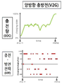
도 1 내지 도 3은 전기자동차의 충전 방식을 나타낸 그래프들.
도 4는 본 발명의 사상에 따른 자율 충방전 제어 방법의 일 실시예를 도시한 흐름도.
도 5는 전원의 전압과 주파수에 대한 충전 및 방전 제어 일례를 도시한 관계도.
도 6은 본 발명의 사상에 따른 자율 제어 충전기의 일 실시예를 도시한 블록도.
도 7 내지 도 9는 본 발명의 사상에 따른 자율 제어 충전기의 다른 실시예들을 도시한 블록도1 to 3 are graphs showing a charging method of an electric vehicle.
4 is a flowchart illustrating an embodiment of an autonomous charge/discharge control method according to the spirit of the present invention.
5 is a relationship diagram illustrating an example of charge and discharge control for voltage and frequency of power supply;
6 is a block diagram illustrating one embodiment of an autonomously controlling charger in accordance with the teachings of the present invention;
7 to 9 are block diagrams illustrating other embodiments of autonomously controlling chargers according to the teachings of the present invention.
본 발명을 설명함에 있어서 제 1, 제 2 등의 용어는 다양한 구성요소들을 설명하는데 사용될 수 있지만, 구성요소들은 용어들에 의해 한정되지 않을 수 있다. 용어들은 하나의 구성요소를 다른 구성요소로부터 구별하는 목적으로만 된다. 예를 들어, 본 발명의 권리 범위를 벗어나지 않으면서 제 1 구성요소는 제 2 구성요소로 명명될 수 있고, 유사하게 제 2 구성요소도 제 1 구성요소로 명명될 수 있다. In describing the present invention, terms such as first and second may be used to describe various components, but the components may not be limited by the terms. Terms are only for the purpose of distinguishing one element from another. For example, a first element may be termed a second element, and similarly, a second element may be termed a first element, without departing from the scope of the present invention.
어떤 구성요소가 다른 구성요소에 연결되어 있다거나 접속되어 있다고 언급되는 경우는, 그 다른 구성요소에 직접적으로 연결되어 있거나 또는 접속되어 있을 수도 있지만, 중간에 다른 구성요소가 존재할 수도 있다고 이해될 수 있다.When a component is referred to as being connected or connected to another component, it may be directly connected or connected to the other component, but it may be understood that another component may exist in the middle. .
본 명세서에서 사용한 용어는 단지 특정한 실시예를 설명하기 위해 사용된 것으로, 본 발명을 한정하려는 의도가 아니다. 단수의 표현은 문맥상 명백하게 다르게 뜻하지 않는 한, 복수의 표현을 포함할 수 있다. Terms used in this specification are only used to describe specific embodiments, and are not intended to limit the present invention. Singular expressions may include plural expressions unless the context clearly dictates otherwise.
본 명세서에서, 포함하다 또는 구비하다 등의 용어는 명세서상에 기재된 특징, 숫자, 단계, 동작, 구성요소, 부품 또는 이들을 조합한 것이 존재함을 지정하려는 것으로서, 하나 또는 그 이상의 다른 특징들이나 숫자, 단계, 동작, 구성요소, 부품 또는 이들을 조합한 것들의 존재 또는 부가 가능성을 미리 배제하지 않는 것으로 이해될 수 있다. In this specification, the terms include or include are intended to designate that there is a feature, number, step, operation, component, part, or combination thereof described in the specification, and one or more other features or numbers, It can be understood that the presence or addition of steps, operations, components, parts, or combinations thereof is not precluded.
또한, 도면에서의 요소들의 형상 및 크기 등은 보다 명확한 설명을 위해 과장될 수 있다.In addition, shapes and sizes of elements in the drawings may be exaggerated for clearer description.
도 1 내지 도 3은 전기자동차의 충전 방식을 나타낸 그래프들이다.1 to 3 are graphs showing a charging method of an electric vehicle.
도 2 또는 도 3과 같이 V1G 충전 제어 또는 V2G 충방전 제어 기술을 적용하면 전력계통의 전압을 유지하고 주파수를 안정화하는데 기여할 수 있다.Applying the V1G charge control or V2G charge and discharge control technology as shown in FIG. 2 or 3 can contribute to maintaining the voltage of the power system and stabilizing the frequency.
V1G 기술은 EV용 배터리로 에너지의 공급(충전)만 가능하나, 공급하는 전력의 크기를 조절하여 전력계통 전체 부하의 크기를 제어할 수 있고, V2G 기술은 충전과 방전이 모두 가능하여 EV용 배터리에서 에너지를 공급 또는 흡수하여 전력계통의 전압 및 주파수 제어에 기여할 수 있다.V1G technology is an EV battery that can only supply (charge) energy, but it can control the size of the entire power system load by adjusting the amount of power supplied, and V2G technology is capable of both charging and discharging. It can contribute to the voltage and frequency control of the power system by supplying or absorbing energy from
하지만, 현재 전기자동차의 배터리 충전은 충전기의 규격 전력으로 또는 EV에서 요구하는 크기로 지속적으로 일정 전력을 공급하고 배터리가 완전히 충전되면 중 지하는 방식으로 작동한다. 다시말해, 현재에는 도 1에 도시한 방식으로만 전기자동차 배터리 충전이 수행된다.However, current electric vehicle battery charging works by continuously supplying a certain amount of power with the standard power of the charger or the size required by the EV and stopping when the battery is fully charged. In other words, charging the battery of an electric vehicle is currently performed only in the manner shown in FIG. 1 .
도 1에 도시한 방식으로 운용되는 현재 충전기는 EV 또는 UAV가 충전기에 연결되는 즉시 정격 전력 또는 EV가 요청하는 전력으로 충전이 시작되고 배터리가 완전히 충전되면 충전이 종료되는 방식, 또는 사용자가 지정한 시간에 정격 전력으로 충전을 하는 방식으로 사용되어 현 상태의 충전기는 연결된 전원이나 전력계통의 상태에 따라 충전중에 충전 전력을 능동적으로 제어가 불가능하다.The current charger operated in the manner shown in FIG. 1 starts charging with the rated power or the power requested by the EV as soon as the EV or UAV is connected to the charger, and ends when the battery is fully charged, or at a time specified by the user. It is used as a method of charging with rated power, and the charger in the current state cannot actively control the charging power during charging according to the connected power source or the state of the power system.
게다가, 기존의 스마트 충전기술은 사용자의 설정과 DR 신호에 따라서 중앙에서 스케쥴을 생성하여 충전기로 보내서 제어를 하므로 충전기의 숫자에 비례하여 계산량과 통신량이 증가하여 속도가 느려진다.In addition, the existing smart charging technology generates a schedule centrally according to the user's setting and DR signal and sends it to the charger for control, so the amount of calculation and communication increases in proportion to the number of chargers, resulting in slowdown.
본 발명에서는 전력망의 상태나 현지의 배전망의 운영 여건에 따라서 충전기가 자율적으로 전기자동차 배터리에 대한 충전 전력을 제어하는 방안, 예컨대, 충전을 위한 계통 전력의 주파수나 전압에 따른 제어 방법을 제시한다.The present invention proposes a method for a charger to autonomously control the charging power for an electric vehicle battery according to the state of the power grid or the operating conditions of the local distribution network, for example, a control method according to the frequency or voltage of the grid power for charging. .
본 발명의 사상에 따른 충전기는 충전기가 연결된 AC 전원의 주파수와 전압 변화를 지속적으로 계측하면서, 사용자 또는 전력회사 또는 충전기 운영자가 미리 설정한 조건에 따라서 충전기 스스로 충전 전력의 크기를 자율적으로 제어하여, 사용자의 충전요구 조건을 만족시키며 충전을 수행한다. 이후, 충전정보를 기록하고 충전중 또는 종료되면 결과를 운영자 또는 전력회사로 전송한다.The charger according to the spirit of the present invention continuously measures the frequency and voltage changes of the AC power to which the charger is connected, and autonomously controls the amount of charging power by the charger itself according to conditions set in advance by the user, electric power company, or charger operator, Charging is performed while satisfying the charging requirements of the user. Then, the charging information is recorded and the result is transmitted to the operator or power company when charging is in progress or terminated.
도 4는 본 발명의 사상에 따른 자율 충방전 제어 방법의 일 실시예를 도시한 흐름도이다.4 is a flowchart illustrating an embodiment of an autonomous charge/discharge control method according to the spirit of the present invention.
도시한 자율 충방전 제어 방법은, 자율 충방전을 위한 설정을 수행하는 단계(S100); 전기자동차가 접속(Plug-In)되면 해당 전기자동차에 대한 충방전제어 스케쥴을 작성하는 단계(S200); 계통 상태 정보로부터 계통 안정화 충방전 제어 수행 여부를 결정하여 상기 충방전제어 스케쥴에 반영하는 단계(S300); 상기 충방전제어 스케쥴에 따라 충방전을 수행하고, 수행 결과를 기록하는 단계(S500)를 포함할 수 있다.The illustrated autonomous charge/discharge control method includes the steps of performing settings for autonomous charge/discharge (S100); When the electric vehicle is connected (plug-in), creating a charge/discharge control schedule for the corresponding electric vehicle (S200); Determining whether or not to perform system stabilization charge/discharge control based on system state information and reflecting the result in the charge/discharge control schedule (S300); It may include performing charge/discharge according to the charge/discharge control schedule and recording the result of charge (S500).
구현에 따라, 전력 가격 정보에 따른 경제적 최적화를 상기 충방전제어 스케쥴에 반영하는 단계(S400)를 더 포함할 수 있다. 상기 S400 단계는 후술하는 경제충전을 수행하기 위함이다.Depending on implementation, a step of reflecting economic optimization according to power price information to the charge/discharge control schedule (S400) may be further included. The step S400 is to perform economic charging, which will be described later.
상기 자율 충방전을 위한 설정을 수행하는 단계(S100)는, 상기 충전기가 계통 안정화 충방전을 수행할 조건으로서, 주파수, 전압, 무효전력 중 하나 이상의 조건을 설정하는 단계; 및 상기 전기자동차의 배터리를 계통 안정화 충방전에 투입할 조건으로서, SoC, SoH, 허여 시간 중 하나 이상의 조건을 설정하는 단계를 포함할 수 있다.The setting for autonomous charging and discharging (S100) may include setting one or more conditions among frequency, voltage, and reactive power as conditions for the charger to perform system stabilization charging and discharging; and setting at least one of SoC, SoH, and allowed time as a condition for inputting the battery of the electric vehicle to system stabilization charging and discharging.
상기 충전기에 대한 조건을 설정하는 단계에서는, 주로 계통안정화를 위한 계통 전력의 조건들로서, 예컨대, 계통이 안정화된 것으로 간주하는 전압 및/또는 주파수에 대한 dead band, 무효전력 제어가 필요한 기준 무효전력 비율값 등을 설정할 수 있다. In the step of setting conditions for the charger, the system power conditions are mainly for system stabilization, for example, a dead band for voltage and/or frequency considered stabilized by the system, and a reference reactive power ratio requiring reactive power control. You can set values, etc.
상기 배터리에 대한 조건을 설정하는 단계에서는, 계통안정화 충방전에 이용될 수 있는 배터리의 SoH 및/또는 SoC의 범위를 설정하거나, 단위 기간당(예: 1달, 1년 등) 계통안정화 충방전에 투입될 수 있는 총 시간이나 총 충방전량을 설정할 수 있다. 또는, 계통안정화가 필요한 전력 계통의 상태 정도를 소정의 등급으로 구분하고, 상기 배터리가 투입되는 등급을 지정할 수도 있다. 이 경우, 전력 계통의 상태 정도의 등급 구분 및 배터리 투입 등급 지정을 계통안정화 제어전략으로 볼 수 있다. In the step of setting conditions for the battery, the range of SoH and/or SoC of the battery that can be used for system stabilization charge/discharge is set, or per unit period (eg, 1 month, 1 year, etc.) It is possible to set the total time or total charge/discharge amount that can be input to Alternatively, the degree of state of the power system requiring system stabilization may be classified into predetermined grades, and the grade into which the battery is input may be designated. In this case, classifying the level of state of the power system and specifying the battery input level can be regarded as a system stabilization control strategy.
도시한 바와 같이, 상기 전기자동차가 접속되면 해당 전기자동차에 대한 충방전제어 스케쥴을 작성하는 단계(S200)는, 전기자동차가 충전기에 접속(Plug-In)됨을 확인하는 단계(S220); 상기 전기자동차에 대한 권한 등을 확인하여 충전을 결정하는 단계(S240); 및 상기 전기자동차 배터리에 대한 충전 스케쥴 및 충방전제어 스케쥴을 생성하는 단계(S260)를 포함할 수 있다.As shown, when the electric vehicle is connected, creating a charge/discharge control schedule for the corresponding electric vehicle (S200) includes confirming that the electric vehicle is connected to a charger (plug-in) (S220); Determining charging by checking authority for the electric vehicle (S240); and generating a charging schedule and a charge/discharge control schedule for the electric vehicle battery (S260).
상기 전기자동차가 접속되면 해당 전기자동차에 대한 충방전제어 스케쥴을 작성하는 단계(S200)는, 상기 전기자동차의 운행 정보에 따라 충전 스케쥴을 작성하는 단계; 및 상기 충전 스케쥴에 연결된 계통의 예상 부하를 적용하여 충방전제어 스케쥴을 작성하는 단계를 포함할 수 있다.If the electric vehicle is connected, creating a charge/discharge control schedule for the corresponding electric vehicle (S200) includes creating a charging schedule according to operation information of the electric vehicle; and creating a charge/discharge control schedule by applying an expected load of a system connected to the charge schedule.
상기 충전 스케쥴은 전기차 사용자가 자신의 업무/생활에 대한 계획/예정에 따라 미리 작성(입력)된 전기자동차의 운행 계획으로부터 생성될 수 있다. 예컨대, 상기 충전 스케쥴은 상기 S220 단계 또는 S240 단계의 수행 시점으로부터, 상기 운행 계획에 따른 예상 출차 시점까지, 상기 배터리에 대한 조건에 기재된 내용(예: SoC)을 만족시키는 충전을 수행할 것으로 생성될 수 있다.The charging schedule may be generated from an electric vehicle driving plan prepared (input) in advance according to a plan/schedule for the user's work/life. For example, the charging schedule is generated to perform charging that satisfies the contents (eg, SoC) described in the conditions for the battery from the time of performing the step S220 or step S240 to the expected departure time according to the driving plan. can
상기 충방전제어 스케쥴은, 상기 충전 스케쥴을 만족시키는 한도내에서, 상기 전기자동차 배터리를 이용하여 계통안정화 제어를 위한 충전 및/또는 방전 계획을 포함할 수 있다. 이를 위해, 연결된 계통의 주파수 변동 정보 및 전압 정보, 무효 전력 정보 등을 실시간 입력받을 수 있다. The charge/discharge control schedule may include a charge and/or discharge plan for system stabilization control using the electric vehicle battery within a limit satisfying the charge schedule. To this end, it is possible to receive real-time input of frequency variation information, voltage information, and reactive power information of the connected system.
상기 충방전제어 스케쥴을 생성하는데 있어서, 계통의 미래 시점의 부하/분산발전의 정도(양)에 대한 반영은, 상기 충방전제어 스케쥴이 규정하는 전체 시간 구간의 전부 또는 일부에 대하여 해당 계통의 부하/분산발전의 예상치를 적용하거나, 시분할된 단위 시간 구역마다 이전 구간에서의 부하/분산발전의 정도를 반영하여 수행할 수 있다.In generating the charge/discharge control schedule, the reflection of the degree (amount) of load/distributed power generation at the future time of the system is the load of the corresponding system for all or part of the entire time interval defined by the charge/discharge control schedule. / It can be performed by applying the estimate of distributed generation or by reflecting the degree of load/distributed generation in the previous section for each time-division unit time zone.
구현에 따라서는, 전기차 사용자가 배터리에 저장된 전력을 상업적으로 판매할 수도 있으며, 상기 충전 스케쥴은 판매용 방전에 대해서도 기재할 수 있으나, 일반적이지 않으므로 충전 스케쥴이라 칭하였다.Depending on the implementation, electric vehicle users may commercially sell the power stored in the battery, and the charging schedule may also describe discharging for sale, but since it is not common, it is referred to as a charging schedule.
상기 계통 안정화 충방전 제어 수행 여부를 상기 충방전제어 스케쥴에 반영하는 단계(S300)는, 연결된 계통의 주파수, 전압, 무효전력 중 적어도 하나 이상으로부터 계통안정화 제어가 필요한지 판단하는 단계(S340); 및 계통안정화 제어가 필요하면, 계통안정화 제어에 따른 상기 전기자동차에 대한 충전 또는 방전 수행하도록 상기 충방전제어 스케쥴을 적용하는 단계(S460)를 포함할 수 있다. The step of reflecting whether or not the system stabilization charge/discharge control is performed on the charge/discharge control schedule (S300) includes determining whether system stabilization control is necessary from at least one of the frequency, voltage, and reactive power of the connected system (S340); and applying the charge/discharge control schedule to charge or discharge the electric vehicle according to the system stabilization control if system stabilization control is required (S460).
상기 전력 가격 정보에 따른 경제적 최적화를 상기 충방전제어 스케쥴에 반영하는 단계(S400)는, 도시한 바와 같이, 전력안정화 충방전 제어가 필요하지 않은 경우에 수행될 수 있으며, 충전 및 방전에 대한 전력 가격 정보에 따라, 경제적으로 사용자에게 유리한 충전 또는 방전을 위한 시간 구간을 결정하는 단계(440); 및 결정된 상기 유리한 충전 또는 방전을 위한 시간 구간에 따라 상기 충방전제어 스케쥴을 변경하는 단계(460)를 포함할 수 있다.The step of reflecting the economic optimization according to the power price information to the charge/discharge control schedule (S400) can be performed when, as shown, power stabilization charge/discharge control is not required, and the power for charge and discharge According to the price information, determining a time period for charging or discharging economically advantageous to the user (440); and changing the charge/discharge control schedule according to the determined time period for the advantageous charge or discharge (460).
상기 충방전을 수행하고, 수행 결과를 기록하는 단계(S500)는, 시각별 충방전을 개량하면서(S520), 상기 전기자동차 배터리에 대한 충전을 제어하는 단계(S540); 충방전 목표 시간 및/또는 목표 SoC에 도달 여부를 확인하는 단계(S560); 및 충방전 목표 시간 및/또는 목표 SoC에 도달되면, 충전을 수행한 것에 대한 정보를 기록하고 상위 서버로 송부하는 단계(S80)를 포함할 수 있다.The step of performing the charging and discharging and recording the performance result (S500) includes controlling charging of the electric vehicle battery while improving charging and discharging at each time (S520) (S540); Checking whether a target charge/discharge time and/or a target SoC have been reached (S560); and when the charging/discharging target time and/or target SoC are reached, recording information about charging and sending the information to a higher server (S80).
상기 충방전 제어 스케쥴에 따라, 상기 S540 단계에서 충방전을 수행함에 있어서, 본 발명의 사상에 따라 전력 계통의 전력 상태에 대한 안정화 서비스로서, V1G 서비스나 V2G 서비스를 수행할 수 있다. 또한, 전력 계통의 주파수를 안정화시키기 위한 주파수 제어 안정화 및/또는 전압을 안정화시키는 전압 제어 안정화를 수행할 수 있다.In performing charging and discharging in step S540 according to the charge and discharge control schedule, V1G service or V2G service may be performed as a stabilization service for the power state of the power system according to the spirit of the present invention. In addition, frequency control stabilization for stabilizing the frequency of the power system and/or voltage control stabilization for voltage stabilization may be performed.
예컨대, 주파수 제어를 위해 V1G 기술이 적용될 경우, 충전기가 사용하는 전원에서 계측된 주파수가 규정주파수 범위를 벗어나 59.9Hz 미만으로 떨어지면 설정에 따라서 충전을 중단하거나 충전 전력을 주파수에 비례하여 또는 단계적으로 50%등으로 감소하고 주파수가 60.1Hz를 초과하면 충전을 시작하거나 주파수에 비례하여 충전 전력을 높여서 충전하여 전체 전력망의 수급 안정에 기여할 수 있다.For example, when V1G technology is applied for frequency control, if the frequency measured from the power source used by the charger falls outside the specified frequency range and falls below 59.9 Hz, charging is stopped or charging power is reduced in proportion to the frequency or in steps of 50 %, etc., and when the frequency exceeds 60.1Hz, charging can be started or charging by increasing the charging power in proportion to the frequency, thereby contributing to stabilizing the supply and demand of the entire power grid.
또는, 주파수 제어를 위해 V2G 기술이 적용될 경우, 충전기가 사용하는 전원에서 계측된 주파수가 규정주파수 범위를 벗어나 59.9Hz 미만으로 떨어지면 설정에 따라서 충전전류의 크기를 감소하고 필요시 방전하는 방향으로 제어하고, 주파수가 60.1Hz를 초과하면 충전전류의 크기를 증가하는 방향으로 제어하여 전체 전력망의 수급 안정에 기여할 수 있다. Alternatively, when V2G technology is applied for frequency control, if the frequency measured from the power source used by the charger falls outside the specified frequency range and falls below 59.9 Hz, the size of the charging current is reduced according to the setting and controlled in the direction of discharging if necessary. However, if the frequency exceeds 60.1 Hz, the charging current can be controlled to increase, contributing to the stability of the supply and demand of the entire power grid.
또한, 방전하는 중간에 발생하는 급격한 주파수 증가시에는 충전으로 바로 전환되어 전력계통으로부터 전력을 흡수할 수도 있다. 즉, 주파수의 증감 변동에 따라 충전과 방전의 즉시 변경 할 수 있다.In addition, when the frequency rapidly increases in the middle of discharging, it is immediately converted to charging and may absorb power from the power system. That is, the charging and discharging can be changed immediately according to the increase or decrease of the frequency.
또는, 전압 제어의 경우, 연결된 전원에서 계측된 전압이 규정전압 범위 또는 설정전압 범위를 벗어나 210V 미만으로 떨어지면 충전을 중단하거나 충전전력을 비례하여 또는 50% 등으로 감소하거나 방전을 시작하여 전압유지에 기여하고, 230V 를 초과하면 충전을 시작하거나 충전전력을 높인다. 또는 전압에 비례하여 충전전력을 가변하여 배전 선로의 전압안정성 확보에 기여 할 수 있다. 여기서, 충방전 전력은 유효전력과 관련된 내용이다.Or, in the case of voltage control, if the voltage measured from the connected power source goes out of the specified voltage range or the set voltage range and falls below 210V, charging is stopped, charging power is reduced in proportion or by 50%, or discharging is started to maintain the voltage. When it exceeds 230V, it starts charging or increases the charging power. Alternatively, the charging power may be varied in proportion to the voltage to contribute to securing voltage stability of the distribution line. Here, the charge/discharge power is content related to active power.
무효전력 제어 혹은 역률제어가 가능한 충전기의 경우, 전원에서 계측된 전압이 규정전압 범위를 벗어나는 경우, 계통 전압을 규정 전압 내로 유지하기 위하여 무효전력을 공급 또는 흡수하는 방향으로 동작하여 계통 전압 안정화에 기여할 수 있다.In the case of a charger capable of reactive power control or power factor control, when the voltage measured from the power source is out of the specified voltage range, it operates in the direction of supplying or absorbing reactive power to maintain the system voltage within the specified voltage, contributing to stabilization of the system voltage. can
그런데, 전기자동차의 배터리는 일반 ESS의 배터리와는 달리 전기자동차의 필요한 운행을 지원하는 것이 주 목적이며, 계통안정화는 부수적인 목적이다. 따라서, 전기자동차 배터리를 이용한 계통안정화 제어는 일반 ESS 등의 경우와 동일하게 적용하면, 전기차 운행에 악영향을 줄 수 있다. 이하, 전기자동차의 배터리에 적합한 계통안정화를 위한 충방전 제어의 전반적인 동작 원리에 대하여 설명한다.However, unlike batteries of general ESS, the main purpose of electric vehicle batteries is to support the necessary operation of electric vehicles, and system stabilization is a secondary purpose. Therefore, if the system stabilization control using the electric vehicle battery is applied in the same way as in the case of a general ESS, it may adversely affect the operation of the electric vehicle. Hereinafter, the overall operation principle of charge/discharge control for system stabilization suitable for a battery of an electric vehicle will be described.
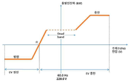
도 5는 전원의 전압과 주파수에 대한 충전 및 방전 제어 일례를 도시한 관계도이다.5 is a relationship diagram illustrating an example of charging and discharging control for voltage and frequency of a power source.
도시한 Dead band은 일반적인 계통이 안정화되었다고 가정하는 주파수/전압 대역이다. ESS 배터리의 경우 높은쪽으로 Dead band를 벗어난 경우 충전을 수행하고, 낮은쪽으로 Dead band를 벗어난 경우 방전을 수행한다.The illustrated dead band is a frequency/voltage band assuming that the general system is stabilized. In the case of ESS batteries, charging is performed when the dead band is out of the high side, and discharging is performed when the dead band is out of the low side.
본 발명이 제안하는 전기자동차 배터리를 이용한 계통안정화 제어의 경우, ESS 배터리의 경우 높은쪽으로 Dead band를 벗어난 경우 충전을 수행하는 것은 ESS의 경우와 유사하다.In the case of system stabilization control using an electric vehicle battery proposed by the present invention, charging is performed when the ESS battery is out of the dead band to the high side, similar to the case of the ESS.
반면, 낮은쪽으로 Dead band를 벗어난 경우에도, 소정의 하위 기준값(R)보다 크면 작은 양으로 계획(스케쥴)에 따른 충전을 유지하며, 상기 하위 기준값(R)보다 작아지면 방전을 수행한다. 마찬가지로 Dead band에서도 계획(스케쥴)에 따른 충전을 유지할 수 있다. 즉, 상기 하위 기준값(R)은 상기 Dead band의 하위 경계값 보다 낮은 값으로 설정될 수 있다.On the other hand, even when the dead band is out of the lower range, charging is maintained according to a plan (schedule) with a small amount if it is greater than a predetermined lower reference value (R), and discharge is performed if it is smaller than the lower reference value (R). Similarly, it is possible to maintain charging according to a plan (schedule) in dead band. That is, the lower reference value R may be set to a lower value than the lower boundary value of the dead band.
다음, 본 발명의 사상에 따른 ‘자율 제어형 충전기’에 대하여 살펴보겠다.Next, a 'autonomous control charger' according to the spirit of the present invention will be looked at.
본 발명의 사상에 따른 ‘자율 제어형 충전기’는 충전기가 연결된 AC 전원에서 주파수와 전압 변화를 지속적으로 계측하면서, 사용자와 전력회사 또는 충전기 운영자가 미리 설정한 충전제어 규칙이나 알고리즘에 따라서 충전기 스스로 전기차나 전기이동체에 공급하는 충전 또는 방전 전력의 크기를 자율적으로 제어하고 기록한다.The 'self-controlling charger' according to the idea of the present invention continuously measures the frequency and voltage changes in the AC power to which the charger is connected, and according to the charging control rules or algorithms set in advance by the user, the electric power company, or the charger operator, the charger itself can charge an electric vehicle or It autonomously controls and records the amount of charging or discharging power supplied to the electric vehicle.
충전기는 충전 전력의 크기 변화를 연속하여 기록하고, 자율 제어가 없을 경우인 정격 충전 전력에 대비하여 제어된 충전전력량과 제어시간을 산정하여 충전이 종료되면 충전기 운영자 또는 전력회사에 보내서 충전 요금 또는 방전보상금을 정산한다.The charger continuously records changes in the amount of charging power, and calculates the controlled charging power amount and control time in preparation for the rated charging power in the absence of autonomous control. settle the compensation
충전기는 충전기 사용자(전기차 충전고객)가 설정한 우선순위에 따라서 정격충전, 경제 충전 또는 자동제어형 자율 충방전을 한다.Depending on the priority set by the charger user (electric vehicle charging customer), the charger performs rated charging, economic charging, or automatically controlled autonomous charging and discharging.
- 정격충전 : 규격전력으로 연속 충전- Rated charging: continuous charging with standard power
- 경제충전 : 충전요금에 최소화 되도록 충전제어- Economic charging: charging control to minimize the charging fee
- 제어충전 : 정격충전 또는 경제충전으로 시작하고, 충전기운영자 또는 DSO 로부터 제어명령을 받아서 충전제어를 하며 충전- Controlled charging: Starts with rated charging or economical charging, and receives control commands from the charger operator or DSO to control charging and charging
- 자율충전 : 경제충전으로 충전을 시작하고, 전압과 주파수를 입력으로 미리 설정된 조건에 따라서 자동적으로 충방전 제어를 하며 충전- Autonomous charging: Starts charging with economic charging, and automatically controls charging and discharging according to preset conditions by inputting voltage and frequency.
자동제어형 충전이 선택된 경우 충전기는 전력회사 또는 충전기 운영자가 설정한 제어 조건이나 DR 요금에 따라서 충전기가 연결된 전력선으로부터 취득한 주파수 정보와 전압 정보에 따라 충전전력 또는 방전전력의 크기를 제어하여 충전을 수행할 수 있다.When automatic control type charging is selected, the charger performs charging by controlling the size of the charging power or discharging power according to the frequency information and voltage information obtained from the power line to which the charger is connected according to the control conditions set by the electric power company or the charger operator or the DR rate. can
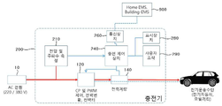
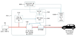
도 6은 본 발명의 사상에 따른 자율 제어 충전기의 일 실시예를 도시한 블록도이다.6 is a block diagram illustrating one embodiment of an autonomously controlling charger in accordance with the teachings of the present invention.
도시한 전기자동차 배터리에 대하여 계통 안정화를 위해 수행하는 자율 충방전을 수행하는 자율 제어 충전기(200)는, 연결된 전력 계통의 상태를 계측하는 계측부(210); 접속된 전기자동차의 배터리를 이용하여 계통 안정화 충방전 제어를 수행하는 충방전 제어부(240); 및 상위 서버로부터 계통 안정화 충방전 제어에 대한 설정 정보를 입력받고, 계통 안정화 충방전 수행 결과를 전송하는 통신부(260)를 포함할 수 있다.The autonomously controlled
구현에 따라, 상기 통신부(260)는, 경제적 최적화를 위한 충방전 제어를 위해 상위 서버로부터 전력 가격 정보를 입력받을 수 있다.Depending on the implementation, the
구현에 따라, 상기 통신부(260)는 항상 온라인 상태로 유지되지 않고, 미리 규정된 통신 시간에 상기 설정 정보나 전력 가격 정보를 전송받아, 자율 제어 충전기(200)의 내부 저장부에 기록할 수 있다.Depending on the implementation, the
상기 충방전 제어부(240)는, 본 발명의 사상에 따른 자율 충방전 제어 방법을 수행할 수 있다. The charge/
예컨대, 상기 충방전 제어부(240)는, 연결된 계통의 주파수, 전압, 무효전력 중 적어도 하나 이상으로부터 계통안정화 제어가 필요한지 판단하고, 상기 전력 계통의 상태가 계통안정화가 필요하다고 판단되면, 상기 계통 안정화 충방전 제어를 수행하고, 그렇지 않으면 상기 전력 가격 정보에 따른 경제적 최적화를 위한 충방전을 수행할 수 있다.For example, the charge/
예컨대, 상기 충방전 제어부(240)는, 상기 통신부(260)로부터 전달받은 상위 서버로부터의 설정 정보에 따라, 상기 충전기가 계통 안정화 충방전을 수행할 조건으로서, 주파수, 전압, 무효전력 중 하나 이상의 조건 설정 및/또는 상기 전기자동차의 배터리를 계통 안정화 충방전에 투입할 조건으로서, SoC, SoH, 허여 시간 중 하나 이상의 조건 설정의 작업을 수행할 수 있다.For example, the charge/
구현에 따라, 상기 충방전 제어부(240)는, 상기 전기자동차의 운행 정보에 따라 충전 스케쥴을 작성하고, 상기 충전 스케쥴에 연결된 계통의 예상 부하를 적용하여 충방전제어 스케쥴을 작성하여, 작성된 충방전제어 스케쥴에 따라 상기 전기자동차 배터리에 대한 충방전을 수행할 수 있다.Depending on the implementation, the charge/
도시한 바와 같이, 상기 계측부(210)는 연결된 전원으로부터 전원주파수와 전압을 연속하여 계측할 수 있다. As shown, the measuring
상기 충방전 제어부(240)는, 상기 계측부(210)에서 계측된 전압 및 주파수로부터 미리 설정된 값과 비교하여 충전 또는 방전 전력을 제어할 수 있다.The charge/
구현에 따라, 도시한 자율 제어 충전기(200)는, 사용자 설정을 입력받고 충전 진행 상태를 표시하는 사용자 인터페이스부(280, 290)를 더 포함할 수 있다. Depending on the implementation, the illustrated autonomously controlled
또는, 상기 전기자동차로 CP/PWM제어, CAN, PLC통신 등의 방법으로 충전 또는 방전 제어 신호를 생성하는 충전차량 제어부(120)를 더 포함할 수 있다. Alternatively, the electric vehicle may further include a charging
또한, DC 충전인 경우 전력변환부(미도시)를 더 포함하며, 시간에 따라서 충전 전력을 기록하는 전력계량부(140)를 더 포함할 수 있다.In addition, in the case of DC charging, a power converter (not shown) may be further included, and a
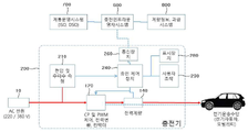
다음, 도시한 충전기와 전기자동차, 상위 서버와의 연결 구성 및 기능 흐름에 대하여 구체적으로 기술한다.Next, the connection configuration and functional flow between the illustrated charger, electric vehicle, and upper server will be described in detail.
충방전 방식은 SAE J1772, IEC61851, ISO15118 표준의 방식 또는 임의의 DC 또는 AC 충방전 방식을 적용할 수 있다.As the charge/discharge method, a method of SAE J1772, IEC61851, ISO15118 standards or any DC or AC charge/discharge method may be applied.
운영자시스템(600)은 일정한 주기마다 충전기로 충전제어 또는 방전제어를 실행하는 주파수 범위와 전압범위 등의 설정값을 전송하고, 충전기(200)는 충전 및 방전전력량과 충방전시 제어된 전력, 전력량, 시간 등을 기록하고 운영자시스템(600)으로 전송한다.The
운영자는 충전기(200)에서 받은 충전 및 제어 데이터를 기반으로 사용요금과 인센티브를 산정한다.The operator calculates the usage fee and incentive based on the charging and control data received from the
운영자시스템(600)은 배전망운영자(DSO)나 전력계통운영자(ISO)와 같은 전력망운영시스템(700)으로부터 충방전 제어를 위한 주파수와 전압 설정값에 대한 정보를 받아서 개별 충전기를 위한 자율 제어 정보를 생성한다.The
운영자시스템(600)은 충전기로부터 얻은 시간별 충전량 및 충전제어량에 대한 정보를 갖고 충전제어보상금과 충전요금 또는 방전보상금을 산정하여 계량정보 및 과금 시스템(800)으로 전송한다.The
경우에 따라서 충전기(200)는 배전망운영자(DSO)나 전력계통운영자(ISO)(700)로부터 직접 제어정보를 받을 수 있다.In some cases, the
도 6의 구성을 가진 충전기(200)가 도 4의 흐름도에 따른 자율 충방전 제어 방법을 수행하는 과정을 구체적으로 예시하면 다음과 같다.A process in which the
충전기(200)는 주기적으로 전력회사 또는 충전기운영자로부터 충전 및 방전 제어를 위한 전압 범위와 전압에 대한 제어값 및 주파수 범위와 주파수에대한 제어값을 받아서 자동제어 조건들을 설정한다(S100). 이때, 충전기(200)는 접속된 전기자동차 사용자의 선택에 따라서 자율충전, 제어형 충전, 경제충전 및 정격 충전방식으로 설정될 수 있다.The
충전을 위해 상기 사용자는 도 4의 전기자동차 접속 단계(S220)에서 kWh 또는 주행거리 또는 배터리충전량(State of Charge, 이하 SoC)을 충전값으로 입력하고 출차시간 또는 충전종료 시각을 입력할 수 있다.For charging, the user may input kWh, mileage, or battery charge amount (State of Charge, hereinafter SoC) as a charging value in the electric vehicle connection step (S220) of FIG. 4 and input the vehicle departure time or charging end time.
충전기(200)는 전원의 전압과 주파수를 연속적으로 계측하다 전압 또는 주파수가 설정된 범위에 도달하면(S340), 제어 설정에 따라서 충전전력 또는 방전전력의 크기를 다단계로 또는 비례제어하여 줄이거나 올릴 수 있다(S360, S540).The
충전기(200)는 충전 또는 방전한 전력량을 시간별로 적산하여 출차시간 또는 충전종료 시각까지(S560) 충전을 완료할 수 있도록 충전 또는 방전제어를 지속하거나 중단한다. 만약, 방전을 할 수 있는 전기이동수단의 경우 전원 전압과 주파수를 계측하다 설정범위로 도달하면 제어 설정에 따라서 방전하도록 제어할 수도 있다.The
상술한 충방전 과정들은 AC 및 DC 충전 및 V2G 충방전기에 적용될 수 있다.The above-described charging and discharging processes can be applied to AC and DC charging and V2G charging and discharging.
도 7 내지 도 9는 본 발명의 사상에 따른 자율 제어 충전기의 다른 실시예들을 도시한 블록도이다.7 to 9 are block diagrams illustrating other embodiments of an autonomously controlling charger according to the teachings of the present invention.
도 7의 자율 제어 충전기는 홈 EMS 서버나 빌딩 EMS 서버에서 계통안정화 충방전 제어를 위한 설정을 수행하는 구현에 따른 것이다.The autonomously controlled charger of FIG. 7 corresponds to an implementation in which settings for system stabilization charge/discharge control are performed in a home EMS server or a building EMS server.
도 7의 자율 제어 충전기(200)는, 충전인프라 충전인프라 운영시스템, 배전망운영자(Distribution System Operator, DSO) 또는 전력계통운영자(Independent System Operator, ISO)로부터 충전 및 방전 제어를 위한 전압 범위와 제어전략 및 충전-방전이 제어되는 주파수 범위를 입력받지 않고 사용자 또는 건물이나 주택의 xEMS가 설정한 전압과 주파수범위 설정에 따라 충전기의 전력 용량범위에서 무효전력과 유효전력을 제어하여 단독으로 자율 동작할 수 있다.The autonomously controlled
또는, 마이크로그리드 또는 단독계통인 경우 주파수와 전압 설정 범위를 단독계통의 EMS로부터 입력받거나 사용자의 초기설정값을 입력으로 하여 충전기의 용량범위에서 단독으로 자율 동작할 수 있다.Alternatively, in the case of a microgrid or a single system, the frequency and voltage setting range can be input from the EMS of the single system or the user's initial setting value can be input to autonomously operate independently within the charger's capacity range.
도 8의 자율 제어 충전기는 충전인프라 운영시스템에서 사용자의 스마트폰과 연계하여 계통안정화 충방전 제어를 수행하는 구현에 따른 것이다.The autonomously controlled charger of FIG. 8 is based on an implementation that performs system stabilization charge/discharge control in conjunction with a user's smartphone in a charging infrastructure operating system.
도 9의 자율 제어 충전기는 홈 EMS 서버나 빌딩 EMS 서버에서 사용자의 스마트폰과 연계하여 계통안정화 충방전 제어를 수행하는 구현에 따른 것이다.The autonomously controlled charger of FIG. 9 is based on an implementation in which a home EMS server or a building EMS server performs system stabilization charge/discharge control in conjunction with a user's smartphone.
도 8 또는 도 9의 충전기(201)는 사용자 조작부 표시장치를 본체에 갖지 아니하고 스마트폰의 앱으로서 조작하고 표시하는 방식의 충전기를 구성한 것이다.The
예컨대, 사용자의 충전 목표값의 입력없이 전기이동체로부터 출차시간, 충전종료시간, 충전량, 방전가능량 등 충전 요구사항에 대한 설정값을 자동으로 전달 받아서 완전 자율로 동작하는 충전기(201)를 구성할 수 있다.For example, it is possible to configure the
본 발명이 속하는 기술 분야의 당업자는 본 발명이 그 기술적 사상이나 필수적 특징을 변경하지 않고서 다른 구체적인 형태로 실시될 수 있으므로, 이상에서 기술한 실시예들은 모든 면에서 예시적인 것이며 한정적인 것이 아닌 것으로서 이해해야만 한다. 본 발명의 범위는 상세한 설명보다는 후술하는 특허청구범위에 의하여 나타내어지며, 특허청구범위의 의미 및 범위 그리고 그 등가개념으로부터 도출되는 모든 변경 또는 변형된 형태가 본 발명의 범위에 포함되는 것으로 해석되어야 한다.Those skilled in the art to which the present invention pertains should understand that the embodiments described above are illustrative in all respects and not limiting, since the present invention can be embodied in other specific forms without changing the technical spirit or essential characteristics thereof. only do The scope of the present invention is indicated by the following claims rather than the detailed description, and all changes or modifications derived from the meaning and scope of the claims and their equivalent concepts should be construed as being included in the scope of the present invention. .
200 : 자율 제어 충전기
210 : 계측부
240 : 충방전 제어부
260 : 통신부
280, 290 : 사용자 인터페이스부
120 : 충전차량 제어부
140 : 전력계량부
600 : 운영자시스템
700 : 계통운영시스템
800 : 계량정보 및 과금 시스템
900 : 마이크로그리드, xEMS
1000 : 사용자 조작 / 표시 장치200: autonomously controlled charger
210: measurement unit
240: charge and discharge control unit
260: communication department
280, 290: user interface unit
120: charging vehicle control unit
140: power metering unit
600: operator system
700: system operation system
800: metering information and billing system
900: microgrid, xEMS
1000: user operation / display device
Claims (15)
자율 충방전을 위한 설정을 수행하는 단계;
전기자동차가 접속되면 해당 전기자동차에 대한 충방전제어 스케쥴을 작성하는 단계;
계통 상태 정보로부터 계통 안정화 충방전 제어 수행 여부를 상기 충방전제어 스케쥴에 반영하는 단계; 및
상기 충방전제어 스케쥴에 따라 충방전을 수행하고, 수행 결과를 기록하는 단계
를 포함하는 자율 충방전 제어 방법.
In the autonomous charge and discharge control method performed for system stabilization of an electric vehicle battery in an electric vehicle charger,
Performing settings for autonomous charging and discharging;
If the electric vehicle is connected, creating a charge/discharge control schedule for the corresponding electric vehicle;
reflecting whether system stabilization charge/discharge control is performed from system state information to the charge/discharge control schedule; and
Performing charge and discharge according to the charge and discharge control schedule and recording the result of the charge and discharge
Autonomous charge and discharge control method comprising a.
상기 계통 안정화 충방전 제어가 필요하지 않은 경우, 전력 가격 정보에 따른 경제적 최적화를 상기 충방전제어 스케쥴에 반영하는 단계
를 더 포함하는 자율 충방전 제어 방법.
According to claim 1,
If the system stabilization charge/discharge control is not required, reflecting economic optimization according to electricity price information to the charge/discharge control schedule
Autonomous charge and discharge control method further comprising a.
상기 자율 충방전을 위한 설정을 수행하는 단계는,
상기 충전기가 계통 안정화 충방전을 수행할 조건으로서, 주파수, 전압, 무효전력 중 하나 이상의 조건을 설정하는 단계; 및
상기 전기자동차의 배터리를 계통 안정화 충방전에 투입할 조건으로서, SoC, SoH, 허여 시간 중 하나 이상의 조건을 설정하는 단계
를 포함하는 자율 충방전 제어 방법.
According to claim 1,
The step of performing the setting for the autonomous charge and discharge,
setting at least one of frequency, voltage, and reactive power as a condition for the charger to perform system stabilization charge and discharge; and
Setting one or more conditions among SoC, SoH, and allowed time as a condition for inputting the battery of the electric vehicle to system stabilization charging and discharging.
Autonomous charge and discharge control method comprising a.
상기 전기자동차가 접속되면 해당 전기자동차에 대한 충방전제어 스케쥴을 작성하는 단계는,
상기 전기자동차의 운행 정보에 따라 충전 스케쥴을 작성하는 단계; 및
상기 충전 스케쥴에 연결된 계통의 예상 부하를 적용하여 충방전제어 스케쥴을 작성하는 단계
를 포함하는 자율 충방전 제어 방법.
According to claim 1,
When the electric vehicle is connected, the step of creating a charge/discharge control schedule for the corresponding electric vehicle,
creating a charging schedule according to driving information of the electric vehicle; and
Creating a charge/discharge control schedule by applying the expected load of the system connected to the charge schedule
Autonomous charge and discharge control method comprising a.
상기 계통 안정화 충방전 제어 수행 여부를 상기 충방전제어 스케쥴에 반영하는 단계는,
연결된 계통의 주파수, 전압, 무효전력 중 적어도 하나 이상으로부터 계통안정화 제어가 필요한지 판단하는 단계; 및
계통안정화 제어가 필요하면, 계통안정화 제어에 따른 상기 전기자동차에 대한 충전 또는 방전 수행하도록 상기 충방전제어 스케쥴을 변경하는 단계
를 포함하는 자율 충방전 제어 방법.
According to claim 1,
In the step of reflecting whether the system stabilization charge/discharge control is performed on the charge/discharge control schedule,
Determining whether grid stabilization control is required from at least one of frequency, voltage, and reactive power of the connected grid; and
If system stabilization control is required, changing the charge/discharge control schedule to charge or discharge the electric vehicle according to system stabilization control.
Autonomous charge and discharge control method comprising a.
상기 전력 가격 정보에 따른 경제적 최적화를 상기 충방전제어 스케쥴에 반영하는 단계는,
충전 및 방전에 대한 전력 가격 정보에 따라, 경제적으로 사용자에게 유리한 충전 또는 방전을 위한 시간 구간을 결정하는 단계; 및
결정된 상기 유리한 충전 또는 방전을 위한 시간 구간에 따라 상기 충방전제어 스케쥴을 변경하는 단계
를 포함하는 자율 충방전 제어 방법.
According to claim 2,
In the step of reflecting economic optimization according to the electricity price information to the charge/discharge control schedule,
determining a time interval for charging or discharging that is economically advantageous to a user according to the electricity price information for charging and discharging; and
Changing the charge/discharge control schedule according to the determined time interval for the favorable charge or discharge.
Autonomous charge and discharge control method comprising a.
상기 충방전을 수행하고, 수행 결과를 기록하는 단계는,
시각별 충방전을 개량하면서, 상기 전기자동차 배터리에 대한 충전을 제어하는 단계;
충방전 목표 시간 또는 목표 SoC에 도달 여부를 확인하는 단계; 및
충방전 목표 시간 또는 목표 SoC에 도달되면, 충전을 수행한 것에 대한 정보를 기록하고 상위 서버로 송부하는 단계
를 포함하는 자율 충방전 제어 방법.
According to claim 1,
The step of performing the charging and discharging and recording the performance result,
controlling charging of the electric vehicle battery while improving charging and discharging at each time;
Checking whether a target charge/discharge time or a target SoC has been reached; and
When the charging/discharging target time or target SoC is reached, recording information about charging and sending it to a higher server
Autonomous charge and discharge control method comprising a.
상기 계통 안정화 충방전 제어를 수행함에 있어서,
일반적인 계통이 안정화되었다고 가정하는 주파수 또는 전압 대역인 Dead band에 대하여, 현재 계통의 주파수 또는 전압이 낮은쪽으로 Dead band를 벗어난 경우에도, 소정의 하위 기준값보다 작아지면 방전을 수행하는 자율 충방전 제어 방법.
According to claim 1,
In performing the system stabilization charge and discharge control,
Regarding the dead band, which is the frequency or voltage band assumed that the general system is stabilized, even if the frequency or voltage of the current system is out of the dead band to the low side, discharge is performed when it is smaller than a predetermined lower reference value. Autonomous charge and discharge control method.
연결된 전력 계통의 상태를 계측하는 계측부;
접속된 전기자동차의 배터리를 이용하여 계통 안정화 충방전 제어를 수행하는 충방전 제어부; 및
상위 서버로부터 계통 안정화 충방전 제어에 대한 설정 정보를 입력받고, 계통 안정화 충방전 수행 결과를 전송하는 통신부
를 포함하는 자율 제어 충전기.
As an autonomously controlled charger that performs autonomous charging and discharging for system stabilization of an electric vehicle battery,
A measurement unit for measuring the state of the connected power system;
a charge/discharge control unit that performs system stabilization charge/discharge control using the battery of the connected electric vehicle; and
Communication unit that receives setting information for system stabilization charge/discharge control from the upper server and transmits the result of system stabilization charge/discharge performance
An autonomously controlled charger comprising a.
상기 충방전 제어부는,
연결된 계통의 주파수, 전압, 무효전력 중 적어도 하나 이상으로부터 계통안정화 제어가 필요한지 판단하는 자율 제어 충전기.
According to claim 9,
The charge and discharge control unit,
An autonomously controlled charger that determines whether grid stabilization control is required from at least one of the connected grid's frequency, voltage, and reactive power.
상기 충방전 제어부는,
상기 전력 계통의 상태가 계통안정화가 필요하다고 판단되면, 상기 계통 안정화 충방전 제어를 수행하고, 그렇지 않으면 상기 전력 가격 정보에 따른 경제적 최적화를 위한 충방전을 수행하는 자율 제어 충전기.
According to claim 10,
The charge and discharge control unit,
If it is determined that the state of the power system requires system stabilization, the system stabilization charge and discharge control is performed, and otherwise, the autonomously controlled charger performs charge and discharge for economic optimization according to the power price information.
상기 계통 안정화 충방전 제어에 대한 설정 정보는,
주파수, 전압, 무효전력 중 하나 이상의 조건을 포함하는 자율 제어 충전기.
According to claim 9,
The setting information for the system stabilization charge and discharge control,
An autonomously controlled charger that includes one or more of the following conditions: frequency, voltage, or reactive power.
상기 충방전 제어부는,
상기 충전기가 계통 안정화 충방전을 수행할 조건으로서, 주파수, 전압, 무효전력 중 하나 이상의 조건을 설정하고, 상기 전기자동차의 배터리를 계통 안정화 충방전에 투입할 조건으로서, SoC, SoH, 허여 시간 중 하나 이상의 조건을 설정하는 자율 제어 충전기.
According to claim 9,
The charge and discharge control unit,
As a condition for the charger to perform grid stabilization charging and discharging, one or more conditions among frequency, voltage, and reactive power are set, and as a condition for putting the battery of the electric vehicle into grid stabilization charging and discharging, among SoC, SoH, and allowed time An autonomously controlled charger that sets one or more conditions.
상기 충방전 제어부는,
상기 전기자동차의 운행 정보에 따라 충전 스케쥴을 작성하고,
상기 충전 스케쥴에 연결된 계통의 예상 부하를 적용하여 충방전제어 스케쥴을 작성하는 자율 제어 충전기.
According to claim 9,
The charge and discharge control unit,
Creating a charging schedule according to the driving information of the electric vehicle;
An autonomously controlled charger that creates a charge/discharge control schedule by applying an expected load of a system connected to the charge schedule.
상기 충방전 제어부는,
상기 계통 안정화 충방전 제어를 수행함에 있어서,
일반적인 계통이 안정화되었다고 가정하는 주파수 또는 전압 대역인 Dead band에 대하여, 현재 계통의 주파수 또는 전압이 낮은쪽으로 Dead band를 벗어난 경우에도, 소정의 하위 기준값보다 작아지면 방전을 수행하는 자율 제어 충전기.
According to claim 9,
The charge and discharge control unit,
In performing the system stabilization charge and discharge control,
Regarding the dead band, which is the frequency or voltage band assumed that the general system is stabilized, even if the frequency or voltage of the current system is out of the dead band to the low side, it is an autonomously controlled charger that discharges when it is less than a predetermined lower reference value.
Priority Applications (1)
| Application Number | Priority Date | Filing Date | Title |
|---|---|---|---|
| KR1020210072095A KR20220163668A (en) | 2021-06-03 | 2021-06-03 | Autonomous control charger and charging/discharging control method for system stabilization |
Applications Claiming Priority (1)
| Application Number | Priority Date | Filing Date | Title |
|---|---|---|---|
| KR1020210072095A KR20220163668A (en) | 2021-06-03 | 2021-06-03 | Autonomous control charger and charging/discharging control method for system stabilization |
Publications (1)
| Publication Number | Publication Date |
|---|---|
| KR20220163668A true KR20220163668A (en) | 2022-12-12 |
Family
ID=84391603
Family Applications (1)
| Application Number | Title | Priority Date | Filing Date |
|---|---|---|---|
| KR1020210072095A KR20220163668A (en) | 2021-06-03 | 2021-06-03 | Autonomous control charger and charging/discharging control method for system stabilization |
Country Status (1)
| Country | Link |
|---|---|
| KR (1) | KR20220163668A (en) |
Citations (1)
| Publication number | Priority date | Publication date | Assignee | Title |
|---|---|---|---|---|
| KR101845241B1 (en) | 2016-07-07 | 2018-04-04 | 한화시스템(주) | Method for selecting charging speed of Multiple electric car charging machine and The multiple electric car charging machine capable of selecting charging speed |
-
2021
- 2021-06-03 KR KR1020210072095A patent/KR20220163668A/en not_active Application Discontinuation
Patent Citations (1)
| Publication number | Priority date | Publication date | Assignee | Title |
|---|---|---|---|---|
| KR101845241B1 (en) | 2016-07-07 | 2018-04-04 | 한화시스템(주) | Method for selecting charging speed of Multiple electric car charging machine and The multiple electric car charging machine capable of selecting charging speed |
Similar Documents
| Publication | Publication Date | Title |
|---|---|---|
| JP6402256B2 (en) | V2G system | |
| Yao et al. | Robust frequency regulation capacity scheduling algorithm for electric vehicles | |
| EP2602901B1 (en) | Power demand-and-supply equalization system | |
| US11498452B2 (en) | Vehicle charging control systems and methods | |
| Yilmaz et al. | Review of the impact of vehicle-to-grid technologies on distribution systems and utility interfaces | |
| US9796286B2 (en) | Energy use aggregation and charge control of a plug-in electric vehicle | |
| US20130197710A1 (en) | Dispatch controller for a distributed electrical power system | |
| JP6402255B2 (en) | Charge / discharge devices and transport equipment | |
| TW201340026A (en) | System and method for management of electric power consumption | |
| US20130110330A1 (en) | Personalized charging management for a vehicle | |
| US11926243B2 (en) | Confidence-based vehicle charge control | |
| JP6393834B2 (en) | Server device | |
| JP2019033629A (en) | Power control method, control device, charging system and program | |
| Zaher et al. | Optimal operation of battery exchange stations for electric vehicles | |
| KR101629807B1 (en) | System and method for controlling particpation-capacity of electric charging station for associating with renewable energy source | |
| JP6835666B2 (en) | Adjustment method, control device, power adjustment system and program | |
| US11180046B2 (en) | Using electric vehicles for long term energy storage | |
| KR20220163668A (en) | Autonomous control charger and charging/discharging control method for system stabilization | |
| US11685282B2 (en) | Electric vehicle charging aggregation | |
| Wali et al. | Cost benefit smart charging schedule for V2G applications | |
| US11677244B2 (en) | Controlling the charge/discharge operations of multiple electric vehicles in a distribution network | |
| US20230046454A1 (en) | Methods and systems for managing vehicle-grid integration | |
| Mody et al. | Optimal charging of electric vehicles using a stochastic dynamic programming model and price prediction | |
| JP2023134156A (en) | Charging and discharging management device, charging and discharging device, vehicle and charging and discharging management method | |
| Mody et al. | Optimal charging of EVs in a real time pricing electricity market |
Legal Events
| Date | Code | Title | Description |
|---|---|---|---|
| E902 | Notification of reason for refusal | ||
| E601 | Decision to refuse application |