KR20220157504A - Steel pipe for pressure piping - Google Patents
Steel pipe for pressure piping Download PDFInfo
- Publication number
- KR20220157504A KR20220157504A KR1020227038419A KR20227038419A KR20220157504A KR 20220157504 A KR20220157504 A KR 20220157504A KR 1020227038419 A KR1020227038419 A KR 1020227038419A KR 20227038419 A KR20227038419 A KR 20227038419A KR 20220157504 A KR20220157504 A KR 20220157504A
- Authority
- KR
- South Korea
- Prior art keywords
- steel pipe
- residual stress
- self
- pressure
- stress
- Prior art date
- Legal status (The legal status is an assumption and is not a legal conclusion. Google has not performed a legal analysis and makes no representation as to the accuracy of the status listed.)
- Granted
Links
Images

Classifications
-
- F—MECHANICAL ENGINEERING; LIGHTING; HEATING; WEAPONS; BLASTING
- F16—ENGINEERING ELEMENTS AND UNITS; GENERAL MEASURES FOR PRODUCING AND MAINTAINING EFFECTIVE FUNCTIONING OF MACHINES OR INSTALLATIONS; THERMAL INSULATION IN GENERAL
- F16L—PIPES; JOINTS OR FITTINGS FOR PIPES; SUPPORTS FOR PIPES, CABLES OR PROTECTIVE TUBING; MEANS FOR THERMAL INSULATION IN GENERAL
- F16L9/00—Rigid pipes
- F16L9/02—Rigid pipes of metal
-
- B—PERFORMING OPERATIONS; TRANSPORTING
- B23—MACHINE TOOLS; METAL-WORKING NOT OTHERWISE PROVIDED FOR
- B23P—METAL-WORKING NOT OTHERWISE PROVIDED FOR; COMBINED OPERATIONS; UNIVERSAL MACHINE TOOLS
- B23P9/00—Treating or finishing surfaces mechanically, with or without calibrating, primarily to resist wear or impact, e.g. smoothing or roughening turbine blades or bearings; Features of such surfaces not otherwise provided for, their treatment being unspecified
-
- C—CHEMISTRY; METALLURGY
- C21—METALLURGY OF IRON
- C21D—MODIFYING THE PHYSICAL STRUCTURE OF FERROUS METALS; GENERAL DEVICES FOR HEAT TREATMENT OF FERROUS OR NON-FERROUS METALS OR ALLOYS; MAKING METAL MALLEABLE, e.g. BY DECARBURISATION OR TEMPERING
- C21D7/00—Modifying the physical properties of iron or steel by deformation
- C21D7/02—Modifying the physical properties of iron or steel by deformation by cold working
- C21D7/10—Modifying the physical properties of iron or steel by deformation by cold working of the whole cross-section, e.g. of concrete reinforcing bars
- C21D7/12—Modifying the physical properties of iron or steel by deformation by cold working of the whole cross-section, e.g. of concrete reinforcing bars by expanding tubular bodies
-
- C21D8/105—
-
- C—CHEMISTRY; METALLURGY
- C21—METALLURGY OF IRON
- C21D—MODIFYING THE PHYSICAL STRUCTURE OF FERROUS METALS; GENERAL DEVICES FOR HEAT TREATMENT OF FERROUS OR NON-FERROUS METALS OR ALLOYS; MAKING METAL MALLEABLE, e.g. BY DECARBURISATION OR TEMPERING
- C21D9/00—Heat treatment, e.g. annealing, hardening, quenching or tempering, adapted for particular articles; Furnaces therefor
- C21D9/08—Heat treatment, e.g. annealing, hardening, quenching or tempering, adapted for particular articles; Furnaces therefor for tubular bodies or pipes
- C21D9/14—Heat treatment, e.g. annealing, hardening, quenching or tempering, adapted for particular articles; Furnaces therefor for tubular bodies or pipes wear-resistant or pressure-resistant pipes
-
- C—CHEMISTRY; METALLURGY
- C22—METALLURGY; FERROUS OR NON-FERROUS ALLOYS; TREATMENT OF ALLOYS OR NON-FERROUS METALS
- C22C—ALLOYS
- C22C38/00—Ferrous alloys, e.g. steel alloys
- C22C38/001—Ferrous alloys, e.g. steel alloys containing N
-
- C—CHEMISTRY; METALLURGY
- C22—METALLURGY; FERROUS OR NON-FERROUS ALLOYS; TREATMENT OF ALLOYS OR NON-FERROUS METALS
- C22C—ALLOYS
- C22C38/00—Ferrous alloys, e.g. steel alloys
- C22C38/002—Ferrous alloys, e.g. steel alloys containing In, Mg, or other elements not provided for in one single group C22C38/001 - C22C38/60
-
- C—CHEMISTRY; METALLURGY
- C22—METALLURGY; FERROUS OR NON-FERROUS ALLOYS; TREATMENT OF ALLOYS OR NON-FERROUS METALS
- C22C—ALLOYS
- C22C38/00—Ferrous alloys, e.g. steel alloys
- C22C38/02—Ferrous alloys, e.g. steel alloys containing silicon
-
- C—CHEMISTRY; METALLURGY
- C22—METALLURGY; FERROUS OR NON-FERROUS ALLOYS; TREATMENT OF ALLOYS OR NON-FERROUS METALS
- C22C—ALLOYS
- C22C38/00—Ferrous alloys, e.g. steel alloys
- C22C38/04—Ferrous alloys, e.g. steel alloys containing manganese
-
- C—CHEMISTRY; METALLURGY
- C22—METALLURGY; FERROUS OR NON-FERROUS ALLOYS; TREATMENT OF ALLOYS OR NON-FERROUS METALS
- C22C—ALLOYS
- C22C38/00—Ferrous alloys, e.g. steel alloys
- C22C38/06—Ferrous alloys, e.g. steel alloys containing aluminium
-
- C—CHEMISTRY; METALLURGY
- C22—METALLURGY; FERROUS OR NON-FERROUS ALLOYS; TREATMENT OF ALLOYS OR NON-FERROUS METALS
- C22C—ALLOYS
- C22C38/00—Ferrous alloys, e.g. steel alloys
- C22C38/18—Ferrous alloys, e.g. steel alloys containing chromium
- C22C38/40—Ferrous alloys, e.g. steel alloys containing chromium with nickel
- C22C38/42—Ferrous alloys, e.g. steel alloys containing chromium with nickel with copper
-
- C—CHEMISTRY; METALLURGY
- C22—METALLURGY; FERROUS OR NON-FERROUS ALLOYS; TREATMENT OF ALLOYS OR NON-FERROUS METALS
- C22C—ALLOYS
- C22C38/00—Ferrous alloys, e.g. steel alloys
- C22C38/18—Ferrous alloys, e.g. steel alloys containing chromium
- C22C38/40—Ferrous alloys, e.g. steel alloys containing chromium with nickel
- C22C38/44—Ferrous alloys, e.g. steel alloys containing chromium with nickel with molybdenum or tungsten
-
- C—CHEMISTRY; METALLURGY
- C22—METALLURGY; FERROUS OR NON-FERROUS ALLOYS; TREATMENT OF ALLOYS OR NON-FERROUS METALS
- C22C—ALLOYS
- C22C38/00—Ferrous alloys, e.g. steel alloys
- C22C38/18—Ferrous alloys, e.g. steel alloys containing chromium
- C22C38/40—Ferrous alloys, e.g. steel alloys containing chromium with nickel
- C22C38/46—Ferrous alloys, e.g. steel alloys containing chromium with nickel with vanadium
-
- C—CHEMISTRY; METALLURGY
- C22—METALLURGY; FERROUS OR NON-FERROUS ALLOYS; TREATMENT OF ALLOYS OR NON-FERROUS METALS
- C22C—ALLOYS
- C22C38/00—Ferrous alloys, e.g. steel alloys
- C22C38/18—Ferrous alloys, e.g. steel alloys containing chromium
- C22C38/40—Ferrous alloys, e.g. steel alloys containing chromium with nickel
- C22C38/48—Ferrous alloys, e.g. steel alloys containing chromium with nickel with niobium or tantalum
-
- C—CHEMISTRY; METALLURGY
- C22—METALLURGY; FERROUS OR NON-FERROUS ALLOYS; TREATMENT OF ALLOYS OR NON-FERROUS METALS
- C22C—ALLOYS
- C22C38/00—Ferrous alloys, e.g. steel alloys
- C22C38/18—Ferrous alloys, e.g. steel alloys containing chromium
- C22C38/40—Ferrous alloys, e.g. steel alloys containing chromium with nickel
- C22C38/50—Ferrous alloys, e.g. steel alloys containing chromium with nickel with titanium or zirconium
-
- F—MECHANICAL ENGINEERING; LIGHTING; HEATING; WEAPONS; BLASTING
- F02—COMBUSTION ENGINES; HOT-GAS OR COMBUSTION-PRODUCT ENGINE PLANTS
- F02M—SUPPLYING COMBUSTION ENGINES IN GENERAL WITH COMBUSTIBLE MIXTURES OR CONSTITUENTS THEREOF
- F02M55/00—Fuel-injection apparatus characterised by their fuel conduits or their venting means; Arrangements of conduits between fuel tank and pump F02M37/00
- F02M55/02—Conduits between injection pumps and injectors, e.g. conduits between pump and common-rail or conduits between common-rail and injectors
-
- C—CHEMISTRY; METALLURGY
- C21—METALLURGY OF IRON
- C21D—MODIFYING THE PHYSICAL STRUCTURE OF FERROUS METALS; GENERAL DEVICES FOR HEAT TREATMENT OF FERROUS OR NON-FERROUS METALS OR ALLOYS; MAKING METAL MALLEABLE, e.g. BY DECARBURISATION OR TEMPERING
- C21D2221/00—Treating localised areas of an article
- C21D2221/10—Differential treatment of inner with respect to outer regions, e.g. core and periphery, respectively
-
- C—CHEMISTRY; METALLURGY
- C21—METALLURGY OF IRON
- C21D—MODIFYING THE PHYSICAL STRUCTURE OF FERROUS METALS; GENERAL DEVICES FOR HEAT TREATMENT OF FERROUS OR NON-FERROUS METALS OR ALLOYS; MAKING METAL MALLEABLE, e.g. BY DECARBURISATION OR TEMPERING
- C21D8/00—Modifying the physical properties of ferrous metals or ferrous alloys by deformation combined with, or followed by, heat treatment
- C21D8/10—Modifying the physical properties of ferrous metals or ferrous alloys by deformation combined with, or followed by, heat treatment during manufacturing of tubular bodies
-
- C—CHEMISTRY; METALLURGY
- C22—METALLURGY; FERROUS OR NON-FERROUS ALLOYS; TREATMENT OF ALLOYS OR NON-FERROUS METALS
- C22C—ALLOYS
- C22C38/00—Ferrous alloys, e.g. steel alloys
-
- C—CHEMISTRY; METALLURGY
- C22—METALLURGY; FERROUS OR NON-FERROUS ALLOYS; TREATMENT OF ALLOYS OR NON-FERROUS METALS
- C22C—ALLOYS
- C22C38/00—Ferrous alloys, e.g. steel alloys
- C22C38/12—Ferrous alloys, e.g. steel alloys containing tungsten, tantalum, molybdenum, vanadium, or niobium
-
- C—CHEMISTRY; METALLURGY
- C22—METALLURGY; FERROUS OR NON-FERROUS ALLOYS; TREATMENT OF ALLOYS OR NON-FERROUS METALS
- C22C—ALLOYS
- C22C38/00—Ferrous alloys, e.g. steel alloys
- C22C38/14—Ferrous alloys, e.g. steel alloys containing titanium or zirconium
-
- F—MECHANICAL ENGINEERING; LIGHTING; HEATING; WEAPONS; BLASTING
- F02—COMBUSTION ENGINES; HOT-GAS OR COMBUSTION-PRODUCT ENGINE PLANTS
- F02M—SUPPLYING COMBUSTION ENGINES IN GENERAL WITH COMBUSTIBLE MIXTURES OR CONSTITUENTS THEREOF
- F02M2200/00—Details of fuel-injection apparatus, not otherwise provided for
- F02M2200/90—Selection of particular materials
- F02M2200/9053—Metals
- F02M2200/9061—Special treatments for modifying the properties of metals used for fuel injection apparatus, e.g. modifying mechanical or electromagnetic properties
-
- F—MECHANICAL ENGINEERING; LIGHTING; HEATING; WEAPONS; BLASTING
- F02—COMBUSTION ENGINES; HOT-GAS OR COMBUSTION-PRODUCT ENGINE PLANTS
- F02M—SUPPLYING COMBUSTION ENGINES IN GENERAL WITH COMBUSTIBLE MIXTURES OR CONSTITUENTS THEREOF
- F02M37/00—Apparatus or systems for feeding liquid fuel from storage containers to carburettors or fuel-injection apparatus; Arrangements for purifying liquid fuel specially adapted for, or arranged on, internal-combustion engines
- F02M37/0011—Constructional details; Manufacturing or assembly of elements of fuel systems; Materials therefor
- F02M37/0017—Constructional details; Manufacturing or assembly of elements of fuel systems; Materials therefor related to fuel pipes or their connections, e.g. joints or sealings
-
- Y—GENERAL TAGGING OF NEW TECHNOLOGICAL DEVELOPMENTS; GENERAL TAGGING OF CROSS-SECTIONAL TECHNOLOGIES SPANNING OVER SEVERAL SECTIONS OF THE IPC; TECHNICAL SUBJECTS COVERED BY FORMER USPC CROSS-REFERENCE ART COLLECTIONS [XRACs] AND DIGESTS
- Y02—TECHNOLOGIES OR APPLICATIONS FOR MITIGATION OR ADAPTATION AGAINST CLIMATE CHANGE
- Y02P—CLIMATE CHANGE MITIGATION TECHNOLOGIES IN THE PRODUCTION OR PROCESSING OF GOODS
- Y02P10/00—Technologies related to metal processing
- Y02P10/20—Recycling
Landscapes
- Chemical & Material Sciences (AREA)
- Engineering & Computer Science (AREA)
- Mechanical Engineering (AREA)
- Organic Chemistry (AREA)
- Materials Engineering (AREA)
- Metallurgy (AREA)
- General Engineering & Computer Science (AREA)
- Crystallography & Structural Chemistry (AREA)
- Physics & Mathematics (AREA)
- Thermal Sciences (AREA)
- Combustion & Propulsion (AREA)
- Manufacturing & Machinery (AREA)
- Heat Treatment Of Articles (AREA)
- Rigid Pipes And Flexible Pipes (AREA)
- Fuel-Injection Apparatus (AREA)
Abstract
자긴 처리가 실시된 압력 배관용 강관으로서, 강관의 외경을 D, 내경을 d, 항복 응력을 σy, 외면의 잔류 응력의 실측값을 σo1, 반할 후의 외면의 잔류 응력의 실측값을 σo2, 반할 후의 내면의 잔류 응력의 실측값을 σi2로 한 경우에, D/d가 1.2 이상이며, [σi1=(-σi2)/(A×(t/T)2-1)], [t/T=((σo2-σo1)/(A×(σo2-σo1)-C×σi2))1/2], [A=3.9829×exp(0.1071×(D/d)2)], [C=-3.3966×exp(0.0452×(D/d)2)]로부터 구해지는, 강관의 내면의 잔류 응력의 추정값 σi1이 [1.1×F×σy≤σi1≤0.8×F×σy](1.2≤D/d≤3.0의 경우는, F=(0.3×(3-D/d)2-1), D/d>3.0의 경우는, F=-1)을 만족하는, 압력 배관용 강관.A steel pipe for pressure piping subjected to self-strengthening treatment, D for the outer diameter of the steel pipe, d for the inner diameter, σ y for the yield stress, σ o1 for the measured value of residual stress on the outer surface, and σ o2 for the measured value of residual stress on the outer surface after halving , when the measured value of the residual stress of the inner surface after halving is σ i2 , D / d is 1.2 or more, [σ i1 = (-σ i2 ) / (A × (t / T) 2 -1)], [t/T=((σ o2 -σ o1 )/(A×(σ o2 -σ o1 )-C×σ i2 )) 1/2 ], [A=3.9829×exp(0.1071×(D/d) 2 )], [C=-3.3966×exp(0.0452×(D/d) 2 )], the estimated value σ i1 of the residual stress on the inner surface of the steel pipe is [1.1×F×σ y ≤ σ i1 ≤ 0.8× F × σ y ] (F = (0.3 × (3-D / d) 2 -1 in the case of 1.2 ≤ D / d ≤ 3.0, F = -1 in the case of D / d > 3.0) steel pipe for pressure piping.
Description
본 발명은, 압력 배관용 강관에 관한 것이다.The present invention relates to a steel pipe for pressure piping.
미래의 에너지 고갈에 대한 대책으로서, 에너지 절약을 촉구하는 운동, 자원의 리사이클 운동 및 이러한 목적을 달성하는 기술의 개발이 활발히 행해지고 있다. 특히 최근에는, 세계적인 대처로서 지구의 온난화를 방지하기 위하여 연료의 연소에 따른 CO2의 배출량을 저감시키는 것이 강하게 요구되고 있다.As a countermeasure against future energy depletion, a movement to promote energy saving, a movement to recycle resources, and development of technologies for achieving these objects are being actively conducted. Particularly in recent years, there has been a strong demand to reduce CO 2 emission due to fuel combustion in order to prevent global warming as a global effort.
CO2의 배출량이 적은 내연기관으로서, 자동차 등에 이용되는 디젤 엔진을 들 수 있다. 그러나, 디젤 엔진에는, CO2의 배출량이 적은 반면, 흑연(黑煙)이 발생한다는 문제가 있다. 흑연은, 분사된 연료에 대해 산소가 부족한 경우에 발생한다. 즉, 연료가 부분적으로 열분해됨으로써 탈수소 반응이 일어나, 흑연의 전구물질이 생성되고, 이 전구물질이 다시 열분해되고, 응집 및 합체됨으로써 흑연이 된다. 이렇게 하여 발생한 흑연은 대기 오염을 일으키고, 인체에 악영향을 미치는 것이 염려된다.As an internal combustion engine with a small amount of CO 2 , a diesel engine used in automobiles and the like is exemplified. However, diesel engines have a problem that, while CO 2 emissions are small, graphite is generated. Graphite occurs when oxygen is insufficient for the injected fuel. That is, a dehydrogenation reaction occurs as a result of partial thermal decomposition of the fuel, and a graphite precursor is generated, and the precursor is thermally decomposed again, aggregated, and coalesced to form graphite. There is a concern that the graphite generated in this way causes air pollution and adversely affects the human body.
상기의 흑연은, 디젤 엔진의 연소실로의 연료의 분사압을 높임으로써, 그 발생량을 저감할 수 있다. 그러나, 그러기 위해서는, 연료 분사에 이용하는 강관에는 높은 피로 강도가 요구된다. 이러한 연료 분사관 또는 연료 분사관용 강관에 대하여, 하기의 기술이 개시되어 있다.The amount of graphite generated can be reduced by increasing the injection pressure of the fuel into the combustion chamber of the diesel engine. However, in order to do so, high fatigue strength is required for steel pipes used for fuel injection. Regarding such fuel injection pipe or steel pipe for fuel injection pipe, the following technique is disclosed.
특허문헌 1에는, 열간 압연한 심리스 강관 소재의 내면을 숏 블라스트 처리에 의해, 연삭·연마를 행한 후에, 냉간 인발 가공을 행하는 디젤 엔진의 연료 분사에 이용하는 강관의 제조 방법이 개시되어 있다. 이 제조 방법을 채용하면, 강관 내면의 흠(요철, 스캡, 미세 크랙 등)의 깊이를 0.10mm 이하로 할 수 있으므로, 연료 분사에 이용하는 강관의 고강도화가 도모된다고 되어 있다.Patent Literature 1 discloses a manufacturing method of a steel pipe used for fuel injection of a diesel engine in which the inner surface of a hot-rolled seamless steel pipe material is ground and polished by shot blasting and then subjected to cold drawing processing. If this manufacturing method is adopted, the depth of flaws (irregularities, scabs, fine cracks, etc.) on the inner surface of the steel pipe can be made 0.10 mm or less, so it is said that the strength of the steel pipe used for fuel injection can be improved.
특허문헌 2에는, 적어도 강관의 내표면으로부터 20μm까지의 깊이에 존재하는 비금속 개재물의 최대 직경이 20μm 이하이며, 인장 강도가 500MPa 이상인 연료 분사관용 강관이 개시되어 있다.
특허문헌 3에는, 인장 강도가 900N/mm2 이상이며, 적어도 강관의 내표면으로부터 20μm까지의 깊이에 존재하는 비금속 개재물의 최대 직경이 20μm 이하인 연료 분사관용 강관이 개시되어 있다.Patent Document 3 discloses a steel pipe for a fuel injection pipe having a tensile strength of 900 N/mm 2 or more and a maximum diameter of non-metallic inclusions present at a depth of at least 20 μm from the inner surface of the steel pipe of 20 μm or less.
특허문헌 3의 발명은, S의 저감, 주입(鑄入) 방법의 고안, Ca의 저감 등에 의해 A계, B계, C계의 조대 개재물을 배제한 강재를 이용하여 소관(素管) 강관을 제조하고, 냉간 가공에 의해 목적으로 하는 직경으로 조정한 후, 담금질, 템퍼링에 의해 900MPa 이상의 인장 강도를 실현하는 것이며, 실시예에서는 260~285MPa의 한계 내압을 실현하고 있다.The invention of Patent Document 3 manufactures a corrugated steel pipe using steel materials from which coarse inclusions of A-, B-, and C-types have been eliminated by reducing S, devising a pouring method, reducing Ca, and the like. After adjusting to the target diameter by cold working, quenching and tempering realize a tensile strength of 900 MPa or more, and in the examples, a limiting withstand pressure of 260 to 285 MPa is realized.
특허문헌 4에는, 800MPa 이상, 바람직하게는 900MPa 이상의 인장 강도를 가지며, 내(耐)내압 피로 특성이 우수한 연료 분사관용 강관 및 그것을 이용한 연료 분사관이 개시되어 있다. 특허문헌 5에는, 비교적 낮은 자긴(自緊) 처리압에 있어서도 높은 한계 내압 향상 효과를 발휘하고, 가공성 및 내내압 피로 특성이 우수한 연료 분사관용 강관이 개시되어 있다.Patent Document 4 discloses a steel pipe for a fuel injection pipe having a tensile strength of 800 MPa or more, preferably 900 MPa or more, and excellent pressure resistance fatigue characteristics, and a fuel injection pipe using the same. Patent Literature 5 discloses a steel pipe for a fuel injection pipe that exhibits a high limiting withstand pressure improvement effect even at a relatively low self-propelling pressure and is excellent in workability and pressure resistance fatigue characteristics.
특허문헌 1에 개시된 방법으로 제조된 연료 분사에 이용하는 강관은, 높은 강도를 갖지만, 그 강관 재료의 강도에 걸맞는 피로 수명을 얻을 수 없다. 강관 재료의 강도가 높아지면, 당연히, 강관의 내측에 가해지는 압력을 높게 할 수 있다. 그러나, 강관의 내측에 압력을 가한 경우에, 강관 내면에 피로에 의한 파괴가 발생하지 않는 한계가 되는 내압(이하, 「한계 내압」이라고 한다.)은, 강관 재료의 강도에만 의존하지 않는다. 즉, 강관 재료의 강도를 크게 해도 기대 이상의 한계 내압은 얻어지지 않는다. 최종 제품의 신뢰성 등을 고려에 넣으면, 피로 수명은 길수록 바람직하지만, 상기의 한계 내압이 낮으면, 높은 내압에 의한 사용에 의해 강관이 피로하기 쉽기 때문에 피로 수명도 짧아진다.Although the steel pipe used for fuel injection manufactured by the method disclosed in Patent Document 1 has high strength, a fatigue life commensurate with the strength of the material of the steel pipe cannot be obtained. When the strength of the steel pipe material increases, naturally, the pressure applied to the inside of the steel pipe can be increased. However, when pressure is applied to the inside of the steel pipe, the internal pressure at which fatigue-induced failure does not occur on the inner surface of the steel pipe (hereinafter referred to as “limiting internal pressure”) does not depend only on the strength of the steel pipe material. That is, even if the strength of the steel pipe material is increased, a limiting withstand pressure higher than expected cannot be obtained. Taking into consideration the reliability of the final product, etc., a longer fatigue life is preferable. However, if the above limiting withstand pressure is low, the fatigue life is also shortened because the steel pipe is easily fatigued due to use with a high withstand pressure.
특허문헌 2 및 3에 개시된 연료 분사관용 강관은, 피로 수명이 길고, 또한 신뢰성이 높다는 특별한 장점을 갖는다. 그러나, 특허문헌 2 및 3에 개시되는 강관이어도, 강관의 인장 강도에 따른 높은 한계 내압이 얻어지고 있다고는 말할 수 없다.The steel pipes for fuel injection pipes disclosed in
그래서, 특허문헌 4 및 5에서는, 높은 한계 내압을 얻기 위하여, 자긴 처리를 행하고 있다. 자긴 처리란, 과대 내압을 작용시킴으로써 내표면 근방을 부분적으로 소성 변형시키고, 압축 잔류 응력을 발생시키는 처리이다. 자긴 처리를 행함으로써, 강관의 인장 강도를 상승시키지 않아도 한계 내압을 증가시키는 것이 가능하다.Therefore, in Patent Literatures 4 and 5, in order to obtain a high limiting withstand voltage, self-growth treatment is performed. The self-strength treatment is a treatment in which an excessive internal pressure is applied to partially plastically deform the vicinity of the inner surface to generate compressive residual stress. By performing the self-stretching treatment, it is possible to increase the limiting withstand pressure without increasing the tensile strength of the steel pipe.
그러나, 자긴 처리에 있어서, 강관의 내표면에 부여하는 압력이 과대하면, 버스트(파열)의 리스크가 높아지기 때문에, 안전성의 면에서 낮게 설정하는 것이 일반적이다. 그 결과, 종래의 기술에서는, 자긴 처리를 행했다고 하여도, 충분히 한계 내압을 높이는 것이 되어 있지 않아, 개선의 여지가 남아 있었다.However, since the risk of burst (rupture) increases when the pressure applied to the inner surface of the steel pipe is excessive in self-stretching treatment, it is common to set it low from the viewpoint of safety. As a result, in the prior art, even if self-treatment was performed, it was not possible to sufficiently increase the limiting internal pressure, leaving room for improvement.
본 발명은 상기의 과제를 해결하여, 높은 한계 내압을 갖는 압력 배관용 강관을 제공하는 것을 목적으로 한다.An object of the present invention is to solve the above problems and provide a steel pipe for pressure piping having a high limit withstand pressure.
본 발명은, 상기의 과제를 해결하기 위하여 이루어진 것이며, 하기의 압력 배관용 강관을 요지로 한다.This invention was made in order to solve the said subject, and makes the following steel pipe for pressure piping a gist.
(1) 자긴 처리가 실시된 압력 배관용 강관으로서,(1) As a steel pipe for pressure piping subjected to self-strengthening treatment,
상기 강관의 외경을 D(mm), 내경을 d(mm), 항복 응력을 σy(MPa)로 하고,The outer diameter of the steel pipe is D (mm), the inner diameter is d (mm), and the yield stress is σ y (MPa),
자긴 처리 후의 상기 강관의 외면의 잔류 응력의 실측값을 σo1(MPa), 자긴 처리 후 또한 반할(半割) 후의 상기 강관의 외면의 잔류 응력의 실측값을 σo2(MPa), 자긴 처리 후 또한 반할 후의 상기 강관의 내면의 잔류 응력의 실측값을 σi2(MPa)로 한 경우에,The measured value of the residual stress on the outer surface of the steel pipe after self-stretching treatment is σ o1 (MPa), the measured value of the residual stress on the outer surface of the steel pipe after self-stretching treatment and after halving is σ o2 (MPa), after self-stretching treatment Further, when the measured value of the residual stress on the inner surface of the steel pipe after halving is σ i2 (MPa),
D/d가 1.2 이상이며,D/d is 1.2 or more,
하기 (i)식~(iv)식에 의해 구해지는, 자긴 처리 후의 상기 강관의 내면의 잔류 응력의 추정값 σi1(MPa)가 하기 (v)식을 만족하는,The estimated value σ i1 (MPa) of the residual stress on the inner surface of the steel pipe after self-treatment, which is obtained by the following equations (i) to (iv), satisfies the following equation (v),
압력 배관용 강관.Steel pipe for pressure piping.
σi1=(-σi2)/(A×(t/T)2-1) …(i)σ i1 =(-σ i2 )/(A×(t/T) 2 -1) . (i)
t/T=((σo2-σo1)/(A×(σo2-σo1)-C×σi2))1/2 …(ii)t/T=((σ o2 -σ o1 )/(A×(σ o2 -σ o1 )-C×σ i2 )) 1/2 . (ii)
A=3.9829×exp(0.1071×(D/d)2) …(iii)A=3.9829×exp(0.1071×(D/d) 2 ) … (iii)
C=-3.3966×exp(0.0452×(D/d)2) …(iv)C=-3.3966×exp(0.0452×(D/d) 2 ) … (iv)
1.1×F×σy≤σi1≤0.8×F×σy …(v)1.1×F×σ y ≤ σ i1 ≤ 0.8×F×σ y … (v)
단, 상기 (v)식 중의 F는 계수이며,However, F in the above formula (v) is a coefficient,
1.2≤D/d≤3.0의 경우는, F=(0.3×(3-D/d)2-1),In the case of 1.2 ≤ D/d ≤ 3.0, F = (0.3 × (3-D / d) 2 -1),
D/d>3.0의 경우는, F=-1로 한다.In the case of D/d > 3.0, F = -1.
본 발명에 의하면, 높은 한계 내압을 갖는 압력 배관용 강관을 안정적으로 얻는 것이 가능해진다.According to the present invention, it becomes possible to stably obtain a steel pipe for pressure piping having a high limiting withstand pressure.
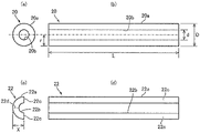
도 1은, 추정 장치에 의해 잔류 응력이 추정되는 자긴 처리 후의 강관의 일례를 나타내는 도면이다.
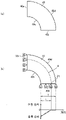
도 2는, 다변수 함수의 도출 방법을 설명하기 위한 도면이다.
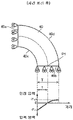
도 3은, 다변수 함수의 도출 방법을 설명하기 위한 도면이다.
도 4는, 다변수 함수의 도출 방법을 설명하기 위한 도면이다.
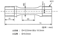
도 5는, 내압 피로 시험편의 형상을 설명하기 위한 도면이다.1 is a diagram showing an example of a steel pipe after self-strengthening treatment in which residual stress is estimated by an estimation device.
2 is a diagram for explaining a method of deriving a multivariate function.
3 is a diagram for explaining a method of deriving a multivariate function.
4 is a diagram for explaining a method of deriving a multivariate function.
5 is a diagram for explaining the shape of a pressure-resistant fatigue test piece.
종래 기술에 있어서, 한계 내압을 충분히 높이기 위한 자긴 처리압을 최적화할 수 없는 요인으로서, 강관의 내면의 잔류 응력을 구하는 방법이 확립되어 있지 않았던 것을 들 수 있다. 또한, 본원 명세서에 있어서 잔류 응력이란, 강관의 둘레 방향에 있어서의 잔류 응력을 의미한다.In the prior art, one of the reasons why it is impossible to optimize the self-actuating pressure for sufficiently increasing the limiting internal pressure is that a method for determining the residual stress on the inner surface of a steel pipe has not been established. In addition, in this specification, residual stress means residual stress in the circumferential direction of a steel pipe.
종래, 본 발명자들은, 자긴 처리 후의 강관을 반할 절단하고, 반할 후의 강관의 내면의 잔류 응력을 측정함으로써, 자긴 처리 후의 강관의 내면의 잔류 응력을 상대적으로 평가하고 있었다. 또한, 반할 절단이란, 축방향에서 보아 강관이 원호 형상의 2개의 부재로 2등분되도록 당해 강관을 절단하는 것을 의미한다.Conventionally, the present inventors relatively evaluated the residual stress on the inner surface of the steel pipe after the self-stretching treatment by cutting the steel pipe after the self-strengthening treatment in half and measuring the residual stress on the inner surface of the steel pipe after the halving. Further, halving means cutting the steel pipe so that the steel pipe is divided into two equal parts into two arc-shaped members when viewed in the axial direction.
그러나, 자긴 처리압을 최적화하여 한계 내압을 충분히 높이기 위해서는, 자긴 처리 후 또한 반할 전의 강관의 내면의 잔류 응력을 정량적으로 평가할 필요가 있다. 그래서, 본 발명자들은, 강관의 내면의 잔류 응력을 정량적으로 평가하기 위한 방법에 대하여 연구를 진행해 왔다. 그 연구 중에, 본 발명자들은, 반할 후의 강관의 내면의 잔류 응력에 더하여, 반할 전후의 강관의 외면의 잔류 응력을 고려함으로써, 자긴 처리 후 또한 반할 전의 강관의 내면의 잔류 응력을 평가하는 것을 검토했다.However, in order to sufficiently increase the limit withstand pressure by optimizing the self-stretching pressure, it is necessary to quantitatively evaluate the residual stress on the inner surface of the steel pipe after the self-stretching and before the splitting. Then, the inventors of the present invention have conducted research on a method for quantitatively evaluating the residual stress on the inner surface of a steel pipe. During the study, the present inventors considered evaluating the residual stress on the inner surface of the steel pipe after self-stretching and before halving by considering the residual stress on the outer surface of the steel pipe before and after halving in addition to the residual stress on the inner surface of the steel pipe after halving. .
본 발명자들은, 우선, 평가 대상이 되는 강관의 해석 모델을 이용하여, 다양한 조건으로 수치 해석(FEM 해석)을 행하고, 자긴 처리에 의해 강관의 각 부에 발생하는 잔류 응력(계산치)을 구했다. 구체적으로는, 본 발명들은, 우선, 수치 해석에 의해, 자긴 처리 후 또한 반할 전의 강관의 외면의 잔류 응력 σo1, 자긴 처리 후 또한 반할 전의 강관의 내면의 잔류 응력 σi1, 자긴 처리 후 또한 반할 후의 강관의 외면의 잔류 응력 σo2, 및 자긴 처리 후 또한 반할 후의 강관의 내면의 잔류 응력 σi2를 구했다.The present inventors first performed numerical analysis (FEM analysis) under various conditions using an analysis model of a steel pipe to be evaluated, and obtained residual stress (calculated value) generated in each part of the steel pipe by self-processing. Specifically, the present invention, first, by numerical analysis, residual stress σ o1 on the outer surface of the steel pipe after self-stretching and before cutting, residual stress σ i1 on the inner surface of the steel pipe after self-stretching and before splitting, after self-stretching and before splitting The residual stress σ o2 of the outer surface of the steel pipe after and the residual stress σ i2 of the inner surface of the steel pipe after the self-stretching and the half-halving were obtained.
상기와 같이 하여 얻어진 각 잔류 응력에 대하여 상세한 검토를 행한 결과, 본 발명자들은, 반할 전의 강관의 내면의 잔류 응력 σi1은, 반할 전의 강관의 외면의 잔류 응력 σo1, 반할 후의 강관의 외면의 잔류 응력 σo2, 및 반할 후의 강관의 내면의 잔류 응력 σi2를 이용하여 고정밀도로 추정할 수 있는 것을 발견했다.As a result of detailed examination of each residual stress obtained as described above, the present inventors found that the residual stress σ i1 on the inner surface of the steel pipe before slicing is the residual stress σ o1 on the outer surface of the steel pipe before slicing, and the residual stress σ o1 on the outer surface of the steel pipe after slicing It was found that the stress σ o2 and the residual stress σ i2 on the inner surface of the steel pipe after halving could be estimated with high accuracy.
그리고, 반할 전의 강관의 내면의 잔류 응력의 추정값 σi1이 소정의 조건을 만족하도록 자긴 처리 조건을 조정함으로써, 높은 한계 내압을 갖는 강관을 안정적으로 얻을 수 있다는 지견을 얻기에 이르렀다.And, by adjusting the self-processing conditions so that the estimated value σ i1 of the residual stress on the inner surface of the steel pipe before splitting satisfies a predetermined condition, the knowledge that a steel pipe having a high limiting withstand pressure can be stably obtained has been obtained.
본 발명은 상기 지견에 의거하여 이루어진 것이다. 이하, 본 발명의 각 요건에 대하여 상세히 설명한다.This invention was made based on the said knowledge. Hereinafter, each requirement of the present invention will be described in detail.
1. 압력 배관용 강관1. Steel pipe for pressure piping
본 발명은, 압력 배관용 강관에 관한 것이다. 압력 배관에는, 유압 실린더, 에어백 강관, 어큐뮬레이터, 수소용 배관, 연료 분사관 등이 포함된다. 또, 높은 내압에 견디기 위해서는, 강관의 내경이 클수록 그에 따라 두께를 두껍게 하는 것이 바람직하다. 강관의 내경이 일정하면, 두께가 두꺼워짐에 따라, 강관의 외경도 커진다. 즉, 높은 내압에 견디기 위해서는, 강관의 내경이 클수록 강관의 외경도 크게 하는 것이 바람직하다. 본 발명에 있어서는, 강관의 외경을 D(mm), 내경을 d(mm)로 한 경우에, D/d가 1.2 이상이 되는 강관을 대상으로 한다. D/d는 1.5 이상인 것이 바람직하고, 2.0 이상인 것이 보다 바람직하다.The present invention relates to a steel pipe for pressure piping. Pressure piping includes hydraulic cylinders, airbag steel pipes, accumulators, hydrogen piping, fuel injection pipes, and the like. In addition, in order to withstand a high internal pressure, it is preferable to increase the thickness accordingly as the inner diameter of the steel pipe increases. If the inner diameter of the steel pipe is constant, as the thickness increases, the outer diameter of the steel pipe also increases. That is, in order to withstand a high internal pressure, it is preferable to increase the outer diameter of the steel pipe as the inner diameter of the steel pipe increases. In the present invention, when D (mm) is the outer diameter of the steel pipe and d (mm) is the inner diameter, a steel pipe having D/d of 1.2 or more is intended. It is preferable that it is 1.5 or more, and, as for D/d, it is more preferable that it is 2.0 or more.
그 외의 치수에 대해서는, 용도에 따라 선택하면 되고, 특별히 제한을 설정할 필요는 없다. 예를 들면, 강관을 유압 실린더로서 이용하는 경우에는, 피스톤의 출력(하중)을 확보하기 위하여, 사용 압력(내압)에 따른 내경이 일반적으로 15~580mm의 범위로부터 선정하는 것이 바람직하다. 또, 내압의 반복에 견딜 수 있도록, 두께는 5~60mm의 범위로부터, 외경은 30~700mm의 범위로부터 선정하는 것이 바람직하다. 내압 피로 강도가 높을수록, 두께를 얇게 할 수 있고, 이에 따라 외경도 정해진다.Other dimensions may be selected according to the purpose, and there is no need to set any particular restrictions. For example, when using a steel pipe as a hydraulic cylinder, in order to secure the output (load) of the piston, it is preferable to select the inner diameter according to the working pressure (internal pressure) from the range of generally 15 to 580 mm. Further, it is preferable to select the thickness from the range of 5 to 60 mm and the outer diameter from the range from 30 to 700 mm so as to withstand repeated internal pressure. The higher the withstand pressure fatigue strength, the thinner the thickness can be, and the outer diameter is also determined accordingly.
강관을 에어백 인플레이터로서 이용하는 경우에는, 강관의 외경은 20~100mm인 것이 바람직하고, 20~60mm인 것이 보다 바람직하다. 강관의 두께는 1~5mm인 것이 바람직하고, 1~4mm인 것이 보다 바람직하다.When using a steel pipe as an airbag inflator, it is preferable that it is 20-100 mm, and, as for the outer diameter of a steel pipe, it is more preferable that it is 20-60 mm. It is preferable that it is 1-5 mm, and, as for the thickness of a steel pipe, it is more preferable that it is 1-4 mm.
강관을 어큐뮬레이터로서 이용하는 경우에는, 강관의 외경은 25~500mm인 것이 바람직하고, 50~400mm인 것이 보다 바람직하다. 강관의 두께는 2~40mm인 것이 바람직하고, 4~30mm인 것이 보다 바람직하다.When using a steel pipe as an accumulator, it is preferable that it is 25-500 mm, and, as for the outer diameter of a steel pipe, it is more preferable that it is 50-400 mm. It is preferable that it is 2-40 mm, and, as for the thickness of a steel pipe, it is more preferable that it is 4-30 mm.
또, 강관을 수소 가스 배관 또는 연료 분사관으로서 이용하는 경우에는, 사용 시에 있어서의 내부의 압력 변동을 줄이기 위하여, 어느 정도의 용량이 필요해진다. 그 때문에, 강관의 내경은 2.5mm 이상인 것이 바람직하고, 3.0mm 이상인 것이 보다 바람직하다. 또, 높은 내압에 견딜 필요가 있기 때문에, 강관의 두께는 1.5mm 이상인 것이 바람직하고, 2.0mm 이상인 것이 보다 바람직하다. 한편, 강관의 외경은 20mm 이하인 것이 바람직하고, 15mm 이하인 것이 보다 바람직하며, 10mm 이하인 것이 더 바람직하다.In addition, when using a steel pipe as a hydrogen gas pipe or a fuel injection pipe, a certain amount of capacity is required to reduce internal pressure fluctuations during use. Therefore, it is preferable that it is 2.5 mm or more, and, as for the inner diameter of a steel pipe, it is more preferable that it is 3.0 mm or more. In addition, since it is necessary to withstand a high internal pressure, the thickness of the steel pipe is preferably 1.5 mm or more, and more preferably 2.0 mm or more. On the other hand, the outer diameter of the steel pipe is preferably 20 mm or less, more preferably 15 mm or less, and still more preferably 10 mm or less.
기계 특성에 대해서도, 용도에 따라 선택하면 되고, 특별히 제한을 설정할 필요는 없다. 그러나, 연료 분사관 또는 유압 실린더 등의 압력 배관으로서 이용하기 위해서는, 강관의 인장 강도는, 500MPa 이상인 것이 바람직하고, 800MPa 이상인 것이 보다 바람직하며, 900MPa 이상인 것이 더 바람직하다. 항복 응력은, 300MPa 이상인 것이 바람직하고, 400MPa 이상인 것이 보다 바람직하며, 500MPa 이상인 것이 더 바람직하다.The mechanical characteristics may also be selected according to the use, and there is no need to set any particular restrictions. However, in order to use it as a pressure pipe such as a fuel injection pipe or a hydraulic cylinder, the tensile strength of the steel pipe is preferably 500 MPa or more, more preferably 800 MPa or more, and still more preferably 900 MPa or more. The yield stress is preferably 300 MPa or more, more preferably 400 MPa or more, and still more preferably 500 MPa or more.
항복비는, 0.50~0.95가 바람직하며, 보다 높은 압력으로 자긴 처리를 행하고, 큰 압축 잔류 응력을 얻기 위해서는, 항복비는 0.60 이상인 것이 보다 바람직하고, 0.70 이상인 것이 더 바람직하다. 또 낮은 압력에 의한 자긴 처리로, 보다 효율적으로 압축 잔류 응력을 도입하기 위해서는, 항복비가 0.90 이하인 것이 바람직하고, 0.85 이하인 것이 더 바람직하다.The yield ratio is preferably 0.50 to 0.95, and the yield ratio is more preferably 0.60 or more, and even more preferably 0.70 or more in order to perform the self-sealing treatment at a higher pressure and obtain a large compressive residual stress. In addition, in order to introduce compressive residual stress more efficiently by self-strength treatment by low pressure, the yield ratio is preferably 0.90 or less, and more preferably 0.85 or less.
또한, 본 발명에 있어서, 강관의 인장 강도는, 강관의 직관부을 잘라 내고, 그 양단면으로부터 일정 길이의 영역(이하, 「그립부」라고 한다.)을 척킹하고, 그립부 사이의 평행부에 신장계를 장착한 다음, 인장 시험을 행함으로써 구한다. 척킹은, 강관 외측 반경보다 얕은 V홈 또는 R홈을 형성한 접촉편을, 유압, 볼트 체결, 또는, 쐐기 지그의 사용에 의해, 그립부를 압압(押壓)함으로써 행한다.In addition, in the present invention, the tensile strength of the steel pipe is measured by cutting a straight pipe portion of the steel pipe, chucking a region of a certain length from both ends thereof (hereinafter referred to as "grip portion"), and measuring the extensometer at the parallel portion between the grip portions. It is obtained by conducting a tensile test after mounting. Chucking is performed by pressing a grip portion of a contact piece formed with a V-groove or an R-groove shallower than the outer radius of the steel pipe by hydraulic pressure, bolt fastening, or use of a wedge jig.
그립부의 길이는 시험 강관이 시험 중에 미끄러지지 않도록, 누름 압력과 시험 하중을 고려하여 결정하면 된다. 또, 평행부의 길이는, 신장계가 장착되고, 또한 파단 직전의 네킹 변형이 척에 의해 영향을 받지 않을 정도로 확보되면 된다. 또한, 강관에 충분한 길이의 직관부가 없는 경우는, 비특허문헌 1에 나타내어지는 바와 같은 박육의 덤벨 형상의 소형 시험편을 잘라 내어 인장 시험을 행해도 된다.The length of the grip part may be determined in consideration of the pressing pressure and the test load so that the test steel pipe does not slip during the test. In addition, the length of the parallel part should be ensured to such an extent that an extensometer is attached and the necking deformation immediately before fracture is not affected by the chuck. In addition, when the steel pipe does not have a straight pipe portion of sufficient length, a thin dumbbell-shaped small test piece as shown in Non-Patent Document 1 may be cut out and subjected to a tensile test.
또, 본 발명에 따른 압력 배관용 강관은, 하기 (I)식을 만족하는 한계 내압을 갖는 것이 바람직하다.In addition, the steel pipe for pressure piping according to the present invention preferably has a limit withstand pressure that satisfies the following formula (I).
IP≥0.44×TS×α …(I)IP≥0.44×TS×α . . . (I)
α=[(D/d)2-1]/[0.776×(D/d)2] …(II)α=[(D/d) 2 -1]/[0.776×(D/d) 2 ] . (II)
단, 상기 (I)식 중의 IP는 강관의 한계 내압(MPa), TS는 강관의 인장 강도(MPa)를 의미하고, α는 상기 (II)식으로 표시되는 값이다. 또, 상기 (II)식 중의 D는 강관의 외경(mm), d는 내경(mm)이다. α는 관의 외경과 내경의 비에 의해 내압과 관 내면의 발생 응력의 관계가 변화되는 것을 보정하는 계수이다.However, IP in the above formula (I) means the limiting withstand pressure (MPa) of the steel pipe, TS means the tensile strength (MPa) of the steel pipe, and α is a value expressed by the above formula (II). In the formula (II), D is the outer diameter (mm) of the steel pipe, and d is the inner diameter (mm). α is a coefficient for correcting the change in the relationship between the internal pressure and the stress generated on the inner surface of the pipe due to the ratio of the outer diameter to the inner diameter of the pipe.
또한, 본 발명에 있어서, 한계 내압이란, 내압 피로 시험에 있어서 최저 내압을 18MPa로 하고, 시간에 대해 정현파를 취하는 반복 내압 변동을 부여하여, 반복수가 107회가 되어도 파손(리크)이 발생하지 않는 최고 내압(MPa)을 의미한다. 구체적으로는, 종축을 최대 내압으로 하고, 횡축을 파손 반복수로 한 S-N선도 상에서, 파손이 발생한 최대 내압의 최소값과, 107회가 되어도 파손되지 않은 최대값의 중간값을 한계 내압으로 한다.In the present invention, the limit withstand pressure means that the minimum withstand pressure is set to 18 MPa in the withstand pressure fatigue test, and a sine wave is given with respect to repeated withstand pressure fluctuations with respect to time. Even if the number of repetitions reaches 10 7 , no breakage (leak) occurs. It means the highest withstand pressure (MPa). Specifically, on the SN diagram in which the vertical axis is the maximum internal pressure and the abscissa is the number of repetitions of failure, the median value between the minimum value of the maximum internal pressure at which failure occurs and the maximum value at which no failure occurs even after 10 7 cycles is taken as the limiting internal pressure.
2. 잔류 응력 추정 모델2. Residual stress estimation model
반할 전의 강관의 내면의 잔류 응력 σi1을 추정하기 위한 모델에 대하여, 상세히 설명한다. 도 1은, 본 모델에 의해 잔류 응력이 추정되는 자긴 처리 후의 강관의 일례를 나타내는 도면이다. 도 1에 있어서, (a)는, 자긴 처리가 실시된 강관(20)의 좌측면도이며, (b)는, (a)에 나타내는 강관(20)의 정면도이며, (c)는, (a)에 나타내는 강관(20)을 반할 절단하여 얻어지는 반할 시료(22)의 좌측면도이며, (d)는, (c)에 나타내는 반할 시료(22)의 정면도이다. 또한, 본 명세서에 있어서 반할 후의 강관이란, 자긴 처리 후의 강관을 반할 절단하여 얻어지는 반할 시료를 의미한다.A model for estimating the residual stress σ i1 on the inner surface of the steel pipe before slicing will be described in detail. 1 is a diagram showing an example of a steel pipe after self-strengthening treatment in which residual stress is estimated by this model. 1, (a) is a left side view of the
본 모델에서는, 자긴 처리 후의 강관(20)의 외면(20a)의 잔류 응력 σo1, 반할 시료(22)의 외면(22a)의 잔류 응력 σo2, 및 반할 시료(22)의 내면(22b)의 잔류 응력 σi2의 실측값을 이용한다. 또한, 상술한 바와 같이 잔류 응력이란, 강관(20)의 둘레 방향에 있어서의 잔류 응력을 의미한다.In this model, the residual stress σ o1 of the
도 1을 참조하여, 잔류 응력을 측정할 때의 강관(20)의 길이 L은, 강관(20)의 외경 D의 3배 이상으로 하는 것이 바람직하고, 예를 들면 30mm 정도로 할 수 있다. 강관(20)을 반할 절단할 때에 절단에 따른 발열이 과잉해지면, 내면에 있어서의 잔류 응력에 영향을 미친다. 이 때문에, 발열이 최대한 없는 절단 방법을 채용할 필요가 있어, 와이어 컷 방전 가공에 의해 반할 절단하는 것이 바람직하다. 이 때, 반할 시료(22)의 측면에서 봤을 때에 있어서, 반할 시료(22)의 절단면(22c)과 외면(22a)의 중심의 거리 X(절단면(22c)에 수직인 방향에 있어서의 거리)는, 강관(20)의 반경 r의 ±5% 이내의 범위가 되도록 제어한다.Referring to Fig. 1, the length L of the
잔류 응력의 측정은, 전해 연마에 의해 강관(20)의 외면(20a) 및 반할 시료(22)의 내면(22b)의 표층을 10μm 이하의 범위에서 제거한 후에 행한다. 측정 방법으로서는, X선 회절에 의한 sin2ψ법을 이용할 수 있으며, 비특허문헌 2에 준거하여 행할 수 있다.The residual stress is measured after removing the
이상의 방법에 의해 실측된 잔류 응력 σo1, σo2, σi2, 그리고 외경 D 및 내경 d를 변수로 하는 다변수 함수에 의해, 잔류 응력 σi1의 추정값을 산출한다.The residual stresses σ o1 , σ o2 , and σ i2 actually measured by the above method and a multivariable function using the outer diameter D and the inner diameter d as variables are used to calculate an estimated value of the residual stress σ i1 .
구체적으로는, 도 2의 (a)에 나타내는 바와 같이, 이차원 평면 변형 요소에 의해, 강관(20)의 횡단면(통축 방향으로 수직인 단면)을 모델화한 원호 형상의 해석 모델(40)(1/4 모델)을 작성한다. 도시는 생략하지만, 해석 모델(40)은, 복수의 요소(메쉬)로 분할되어 있다. 해석 모델(40)의 물성값은, 탄성체로 한다.Specifically, as shown in Fig. 2 (a), an arc-shaped analytical model 40 (1/ 4 model). Although not shown, the
우선, 강관(20)을 모의하기 위하여, 도 2의 (b)에 나타내는 바와 같이, 해석 모델(40)의 둘레 방향에 있어서의 양단부(40a, 40b)의 둘레 방향으로의 이동을 규제하도록, 구속 조건을 설정한다. 그 후, 초기 상태로서, 자긴 처리 시의 강관(20) 상태를 모의한 체적력을 설정한다. 구체적으로는, 초기 상태에서는, 해석 모델(40)의 내면(40c)에 둘레 방향의 압축 잔류 응력(-100MPa)을 부여한다.First, in order to simulate the
또, 초기 상태에서는, 내면(40c)으로부터 해석 모델(40)의 경방향(徑方向)으로 떨어진 위치 P(원호 형상의 파선으로 나타내는 위치)와 외면(40d) 사이의 영역에는, 응력이 발생하지 않은 것으로 한다. 또한, 초기 상태에서는, 내면(40c)과 위치 P 사이의 영역의 응력 분포는, 내면(40c)으로부터 위치 P를 향해 압축 응력이 점차 저하되도록, 선형 분포로 했다. 또한, 도 2의 (b), 그리고 후술의 도 3 및 도 4에는, 단부(40b)에 있어서의 응력 상태가 나타내어져 있다. 이하에 있어서는, 단부(40b) 상에 있어서 압축 응력이 0이 되는 점 P1과 내면(40c)의 경방향에 있어서의 거리를, 거리 t라고 기재하고, 해석 모델(40)의 두께를, 두께 T라고 기재한다. 또한, 단부(40b) 상에 있어서 압축 응력이 0이 되는 점이 복수 있는 경우는, 내면(40c)에 가까운 쪽의 일점을 P1로 한다.In addition, in the initial state, no stress is generated in the region between the
상기와 같이 체적력을 설치한 후, 탄성 해석을 실시하고, 응력을 재배분한다. 이에 의해, 예를 들면, 도 3에 나타내는 바와 같이, 해석 모델(40)의 응력 상태가 변화한다. 또한, 도 3에 있어서는, 응력이 0이 되어 있는 위치를 파선으로 나타내고 있다. 파선보다 내측의 영역에서는, 둘레 방향의 압축 응력이 발생하고, 파선보다 외측의 영역에서는, 둘레 방향의 인장 응력이 발생하고 있다. 도 3에 나타내는 상태에서는, 해석 모델(40)의 전체의 응력 분포의 적분값은 0이 된다. 도 3에 나타내는 응력 상태가, 자긴 처리 후의 강관(20)의 응력 상태에 대응한다. 그리고, 도 3에 나타내는 상태에 있어서, 내면(40c)과 단부(40b)의 교점의 응력을, 자긴 처리 후의 강관(20)의 내면(20b)의 잔류 응력 σi1로서 취득하고, 외면(40d)과 단부(40b)의 교점의 응력을, 자긴 처리 후의 강관(20)의 외면(20a)의 잔류 응력 σo1로서 취득한다.After establishing the body force as described above, an elastic analysis is performed and the stress is redistributed. Thereby, as shown in FIG. 3, for example, the stress state of the
다음으로, 반할 시료(22)(반할 후의 강관(20))를 모의하기 위하여, 도 4에 나타내는 바와 같이, 단부(40a)의 구속을 해제하고, 탄성 해석을 실시한다. 이에 의해, 해석 모델(40)의 응력 상태가 더욱 변화한다. 또한, 도 4에 있어서는, 응력이 0이 되어 있는 위치를 파선으로 나타내고 있다. 도 4에 나타내는 예에서는, 해석 모델(40)에 있어서, 경방향에 있어서의 중앙부에는, 둘레 방향의 인장 응력이 발생하고, 내면(40c)을 따르는 원호 형상의 영역 및 외면(40d)을 따르는 원호 형상의 영역에는, 둘레 방향의 압축 응력이 발생하고 있다.Next, in order to simulate the slicing sample 22 (the
또, 도 4에 나타내는 해석 모델(40)에서는, 단부(40a)가 반할 시료(22)의 절단면(22c)(도 1을 참조)에 대응하고, 단부(40b)가 반할 시료(22)의 둘레 방향에 있어서의 중심부(22d)(도 1을 참조)에 대응한다. 그리고, 도 4에 나타내는 상태에 있어서, 내면(40c)과 단부(40b)의 교점의 응력을, 반할 시료(22)의 내면(22b)의 잔류 응력 σi2로서 취득하고, 외면(40d)와 단부(40b)의 교점의 응력을, 반할 시료(22)의 외면(22a)의 잔류 응력 σo2로서 취득한다.In addition, in the
임의의 치수의 강관(20)에 대하여, 도 2의 (b), 도 3 및 도 4로 설명한 상기의 해석을, 초기 상태에 있어서의 거리 t를 다양하게 변화시켜(즉, 도 2의 (b)에 있어서 압축 응력이 0이 되는 점 P1의 위치를 변화시켜) 행한다.Regarding the
본 발명자들의 다양한 검토의 결과, 강관(20)의 두께 T, 그리고 상기와 같이 하여 구해지는 자긴 처리 후의 강관(20)에 있어서의 거리 t(도 3을 참조), 강관(20)의 외면(20a)의 잔류 응력 σo1(도 3을 참조), 강관(20)의 내면(20b)의 잔류 응력 σi1(도 3을 참조), 반할 시료(22)의 외면(22a)의 잔류 응력 σo2(도 4를 참조), 및 반할 시료(22)의 내면(22b)의 잔류 응력 σi2(도 4를 참조)의 사이에는, 일정한 관계가 있는 것을 알 수 있었다.As a result of various studies by the present inventors, the thickness T of the
구체적으로는, 본 발명자들은, 자긴 처리 후의 강관(20)에 있어서의 (t/T)2의 값과 (σi2/-σi1)의 값 사이에, 일정한 상관이 있는 것을 발견했다. 그리고, (t/T)2의 값과 (σi2/-σi1)의 값의 관계를 최소 제곱법으로 선형 근사함으로써, 하기 (1)식을 구했다. 또한, 하기 (1)식에 있어서, A 및 B는 계수이다.Specifically, the present inventors discovered that there is a certain correlation between the value of (t/T) 2 and the value of (σ i2 /-σ i1 ) in the
σi2/(-σi1)=A×(t/T)2-B …(1)σ i2 /(-σ i1 )=A×(t/T) 2 -B . (One)
상기 (1)식을 σi1에 대하여 정리하여, 하기 (i)식이 얻어진다. 또한, 본 발명에 있어서는, A는 하기 (iii)식으로 표시되는 값으로 하고, B는 1로 했다.By arranging the above expression (1) for σ i1 , the following expression (i) is obtained. In addition, in this invention, A was set as the value represented by the following formula (iii), and B was set as 1.
σi1=(-σi2)/(A×(t/T)2-1) …(i)σ i1 =(-σ i2 )/(A×(t/T) 2 -1) . (i)
A=3.9829×exp(0.1071×(D/d)2) …(iii)A=3.9829×exp(0.1071×(D/d) 2 ) … (iii)
또, 본 발명자들은, 자긴 처리 후의 강관(20)에 있어서의 (t/T)2의 값과 ((σo2-σo1)/(-σi1))의 값 사이에도, 일정한 상관이 있는 것을 발견했다. 그리고, (t/T)2의 값과 ((σo2-σo1)/(-σi1))의 값의 관계를 최소 제곱법으로 선형 근사함으로써, 하기 (2)식을 구했다. 또한, 하기 (2)식에 있어서, C 및 E는 계수이다.In addition, the present inventors found that there is a certain correlation between the value of (t/T) 2 and the value of ((σ o2 -σ o1 )/(-σ i1 )) in the
(σo2-σo1)/(-σi1)=-C×(t/T)2-E …(2)(σ o2 -σ o1 )/(-σ i1 )=-C×(t/T) 2 -E . (2)
상기 (1)식 및 (2)식으로부터, (t/T)는, 하기 (3)식으로 표시할 수 있다.From the above formulas (1) and (2), (t/T) can be expressed by the following formula (3).
t/T=((B×(σo2-σo1)-E×σi2)/(A×(σo2-σo1)-C×σi2)) 1/2 …(3)t/T=((B×(σ o2 -σ o1 )-E×σ i2 )/(A×(σ o2 -σ o1 )-C×σ i2 )) 1/2 . (3)
또한, 본 발명에 있어서는, B는 1로 하고, E는 0으로 하여, 하기 (ii)식이 얻어진다. 또, C는 하기 (iv)식으로 표시되는 값으로 했다.Further, in the present invention, when B is set to 1 and E is set to 0, the following formula (ii) is obtained. In addition, C was set as the value represented by the following formula (iv).
t/T=((σo2-σo1)/(A×(σo2-σo1)-C×σi2)) 1/2 …(ii)t/T=((σ o2 -σ o1 )/(A×(σ o2 -σ o1 )-C×σ i2 )) 1/2 . (ii)
C=-3.3966×exp(0.0452×(D/d)2) …(iv)C=-3.3966×exp(0.0452×(D/d) 2 ) … (iv)
이상의 추정 모델로부터 얻어지는 (i)식~(iv)식에 의해, 자긴 처리 후의 강관(20)의 내면(20b)의 잔류 응력의 추정값 σi1을 산출할 수 있다.The estimated value σ i1 of the residual stress of the
그리고, 본 발명에 따른 강관은, σi1의 값이 하기 (v)식을 만족한다.And, in the steel pipe according to the present invention, the value of σ i1 satisfies the following equation (v).
1.1×F×σy≤σi1≤0.8×F×σy …(v)1.1×F×σ y ≤ σ i1 ≤ 0.8×F×σ y … (v)
단, 상기 (v)식 중의 F는 계수이며,However, F in the above formula (v) is a coefficient,
1.2≤D/d≤3.0의 경우는, F=(0.3×(3-D/d)2-1),In the case of 1.2 ≤ D/d ≤ 3.0, F = (0.3 × (3-D / d) 2 -1),
D/d>3.0의 경우는, F=-1로 한다.In the case of D/d > 3.0, F = -1.
자긴 처리에 의해, σi1을 강관의 항복 응력과의 관계에 있어서, 0.8×F×σy 이하로 함으로써, 높은 한계 내압이 얻어지게 된다. 한편, σi1이 1.1×F×σy를 밑도는 경우, 외면 측의 인장 잔류 응력이 커지고, 한계 내압의 상승이 포화될 뿐만 아니라, 오히려 저하될 우려가 있다.By the self-stretching process, when σ i1 is 0.8 × F × σ y or less in relation to the yield stress of the steel pipe, a high limiting withstand pressure is obtained. On the other hand, when σ i1 is less than 1.1 × F × σ y , the tensile residual stress on the outer surface side increases, and the increase in the limiting internal pressure not only saturates, but may even decrease.
3. 제조 방법3. Manufacturing method
본 발명에 따른 압력 배관용 강관의 제조 방법에 대하여 특별히 제한은 없지만, 예를 들면, D/d가 1.2 이상인 복수의 강관 소재에 대해, 다양한 조건으로 자긴 처리를 행하고, 얻어진 각 강관에 대하여, 상술의 방법에 의해 σi1을 구하고, 상기 (v)식을 만족하는 강관을 선별하는 공정을 행함으로써 제조할 수 있다.Although there is no particular restriction on the manufacturing method of the steel pipe for pressure piping according to the present invention, for example, with respect to each steel pipe obtained by performing self-treatment under various conditions for a plurality of steel pipe materials having a D / d of 1.2 or more, It can be manufactured by obtaining σ i1 by the method of and performing a step of selecting a steel pipe that satisfies the above expression (v).
또한, 자긴 처리 조건에 대해서는, 예를 들면, 자긴 처리압 및/또는 자긴 처리 시간을 제어함으로써, σi1이 상기 (v)식을 만족하도록 조정하는 것이 가능하다. 상술한 바와 같이, 자긴 처리 후 또한 반할 전의 강관의 내면의 잔류 응력을 정확히 추정함으로써, 자긴 처리 조건을 최적화할 수 있고, 높은 한계 내압을 갖는 강관을 안정적으로 얻는 것이 가능해진다.Regarding the self-extracting processing conditions, it is possible to adjust σ i1 so as to satisfy the above expression (v) by, for example, controlling the self-extracting processing pressure and/or the self-extracting processing time. As described above, by accurately estimating the residual stress on the inner surface of the steel pipe after the self-strengthening process and before the splitting, it is possible to optimize the self-strength process conditions and stably obtain a steel pipe having a high limiting withstand pressure.
또, 상기의 강관에 대해, 예를 들면 그 양단 부분에 접속 머리부를 형성함으로써, 고압 연료 분사관으로 할 수 있다.Further, the above steel pipe can be made into a high-pressure fuel injection pipe by, for example, forming connection heads at both ends thereof.
이하, 실시예에 의해 본 발명을 보다 구체적으로 설명하지만, 본 발명은 이들 실시예에 한정되는 것은 아니다.Hereinafter, the present invention will be described more specifically with reference to examples, but the present invention is not limited to these examples.
실시예Example
표 1에 나타내는 화학 조성을 갖는 강을 진공 용해로에서 용제하여 잉곳을 얻었다. 이 잉곳을 1250℃로 가열한 다음, 열간 단신(鍛伸)을 행하여, 직경 20mm의 둥근 봉을 얻었다. 또한, 당해 둥근 봉을 1000℃로 가열하고 10분 유지 후에 방랭하는 용체화 처리를 행하여, 시험편의 소재로 했다. 그리고, 조(粗)기계 가공, 열처리, 마무리 가공을 행하여, 도 5에 나타내는 형상의 내압 피로 시험편을 얻었다. 여기서, 조기계 가공 후의 형상은, 도 5의 마무리 가공 후의 형상에 대해, 외경이 1mm 크고, 내경이 1mm 작은 형상으로 했다. 또한, 도 5에 기재된 길이의 단위는 mm이다.Steel having the chemical composition shown in Table 1 was melted in a vacuum melting furnace to obtain an ingot. After heating this ingot to 1250 degreeC, hot forging was performed, and the round rod of 20 mm diameter was obtained. In addition, the round bar was heated at 1000 ° C., held for 10 minutes, and then subjected to a solution heat treatment to cool, and it was used as a material for a test piece. Then, rough machining, heat treatment, and finishing were performed to obtain a pressure-resistant fatigue test piece having a shape shown in FIG. 5 . Here, the shape after early machining was set to be 1 mm larger in outer diameter and smaller by 1 mm in inner diameter compared to the shape after finishing in FIG. 5 . In addition, the unit of length described in FIG. 5 is mm.

열처리 조건은, 1000℃로 가열하고 10분 유지 후 공랭의 소준 처리한 것과, 고주파 가열에 의해 1000℃까지 가열하고 급랭하고, 640℃로 가열하고 15분 유지 후 방랭하는 담금질 템퍼링 처리를 행한 것의 2종류로 했다. 여기서, 전자를 소준품, 후자를 소입품으로 구별하여 부르는 것으로 한다. 도 5의 시험편 형상에 있어서, 소준품의 외경은 12.0mm 또는 18.0mm, 소입품의 외경은 9.0mm이다. 즉, 내경 d에 대한 외경 D의 비 D/d는 소준품에서 2.0 또는 3.0, 소입품에서 1.5이다. 또, 내면에 대해서는 연마 처리를 행하여, 표면 거칠기 Ra(산술 평균 거칠기)가 0.2μm 이하가 되도록 했다.The heat treatment conditions were quenching treatment by heating to 1000 ° C, holding for 10 minutes and then air cooling, heating to 1000 ° C by high frequency heating and rapid cooling, heating to 640 ° C, holding for 15 minutes and then cooling. made in kind. Here, the former is referred to as a refined product and the latter as a cured product. In the shape of the test piece in Fig. 5, the outer diameter of the crude product is 12.0 mm or 18.0 mm, and the outer diameter of the hardened product is 9.0 mm. That is, the ratio D/d of the outer diameter D to the inner diameter d is 2.0 or 3.0 for the roughed product and 1.5 for the hardened product. In addition, polishing treatment was performed on the inner surface so that the surface roughness Ra (arithmetic mean roughness) was 0.2 μm or less.
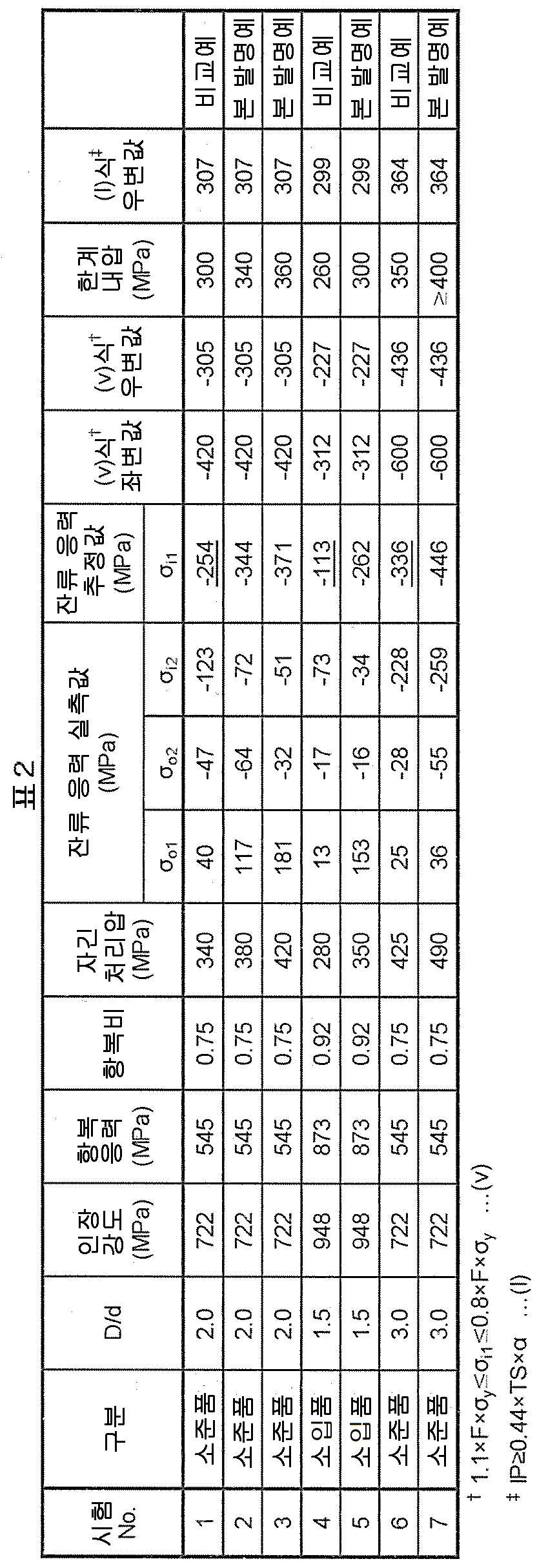
내압 피로 시험편 중 하나로부터 비특허문헌 1에 나타내어지는 박육 덤벨 형상의 소형 시험편을 잘라 내고, 인장 시험을 행하여, 기계적 성질을 평가했다. 그 결과를 표 2에 나타낸다. 소준품보다 소입품 쪽이 인장 강도, 항복 응력 및 항복비가 높은 것을 알 수 있다.A thin dumbbell-shaped small test piece shown in Non-Patent Document 1 was cut out from one of the pressure-resistant fatigue test pieces, and a tensile test was performed to evaluate the mechanical properties. The results are shown in Table 2. It can be seen that the tensile strength, yield stress and yield ratio are higher in the quenched product than in the crude product.
계속해서, 얻어진 내압 피로 시험편에 대해, 자긴 처리를 행했다. 자긴 처리는, 도 5의 내압 피로 시험편의 편측 단면을 시일하고, 다른 편측 단면으로부터 시험편 내부에 압력 매체로서 작동유를 봉입하고, 봉입부의 내압을 제어하여 행했다. 자긴 처리는, 봉입부의 내압을 자긴 처리압 Paf까지 상승시키고, 제하(除荷)함으로써 행하는 것이다. 자긴 처리압은, 소준품에서 3수준, 소입품에서 2수준으로 하고, 각각의 자긴 처리압에 대하여, 복수개의 시험편을 처리했다.Subsequently, a self-stretching treatment was performed on the obtained pressure-resistant fatigue test piece. The self-sealing treatment was performed by sealing one end face of the pressure-resistant fatigue test piece in FIG. 5, sealing hydraulic oil as a pressure medium into the test piece from the other end face, and controlling the internal pressure of the sealed portion. The self-strengthening treatment is performed by raising the internal pressure of the sealing portion to the self-stretching pressure P af and then unloading it. The self-strength treatment pressure was set at 3 levels for raw products and 2 levels for quenched products, and a plurality of test pieces were treated for each self-strength treatment pressure.
자긴 처리 후의 시험편 중 1개를, 잔류 응력 측정에 제공했다. 우선, 전해 연마에 의해 시험편의 길이 방향 중앙 위치 외면의 표층을 10μm 이하의 범위에서 제거한 후, 둘레 방향 잔류 응력 σo1을 측정한다. 측정 방법으로서는, X선 회절에 의한 sin2ψ법을 이용해, 비특허문헌 2에 준거하여 행했다. 상세한 측정 조건은 이하에 나타내는 바와 같다.One of the test pieces after self-treatment was subjected to residual stress measurement. First, after removing the surface layer of the outer surface at the central position in the longitudinal direction of the test piece in a range of 10 μm or less by electrolytic polishing, the residual stress σ o1 in the circumferential direction is measured. As a measuring method, it was carried out based on
· 주사법: 측경법(側傾法), η 일정법(PSPC법)· Scan method: Side view method, η constant method (PSPC method)
· X선 응력 측정 장치: 주식회사 리가크 제조 PSPC-RSF· X-ray stress measuring device: PSPC-RSF manufactured by Rigak Co., Ltd.
· 특성 X선: Crkα· Characteristic X-ray: Crkα
· 측정 회절면: α-Fe211· Measurement diffraction surface: α-Fe211
· 입사 슬릿: 싱글 콜리메이터, 직경 0.3mmEntrance slit: single collimator, diameter 0.3mm
· 입사각(ψ): 0о, 12.9о, 18.5о, 22.8о, 26.6о, 30.0о, 33.3о, 36.3о, 39.3о Angle of incidence (ψ): 0 о , 12.9 о , 18.5 о , 22.8 о , 26.6 о , 30.0 о , 33.3 о , 36.3 о , 39.3 о
· 입사각(ψ): ψP축 요동±3о Incidence angle (ψ): ψ P -axis fluctuation ±3 о
· 회절각 결정법: 반가폭법· Diffraction angle determination method: half width method
· 응력 상수(K): -318MPa/о · Stress constant (K): -318MPa/ о
또한, 이하에 나타내는 잔류 응력 측정 조건에 대해서도, 모두 상기한 바와 같이 했다.In addition, all of the residual stress measurement conditions shown below were carried out as described above.
다음으로, 외면의 잔류 응력을 측정한 시험편을, 와이어 컷 방전 가공에 의해 관축 방향으로 반할 절단한다. 절단 위치는 상기 외면 잔류 응력 측정 위치를 둘레 방향 0о로 한 경우에 ±90о 근방으로 한다. 반할 후의 각 시료의 절단면과 길이 방향 중앙 위치의 외면의 두께 t는, D/2±0.2mm의 범위로 한다.Next, the test piece in which the residual stress on the outer surface is measured is cut in half in the tube axis direction by wire-cut electric discharge machining. The cutting position is set to be around ±90 ° when the outer surface residual stress measurement position is set to 0 ° in the circumferential direction. The thickness t of the cut surface of each sample after slicing and the outer surface at the central position in the longitudinal direction is within the range of D/2±0.2 mm.
그리고, 반할 후의 시료에 있어서 상기한 반할 전 외면 잔류 응력 측정 위치에서 둘레 방향 잔류 응력 σo2를 재차 측정한다. 또한, 반할 후의 전해 연마에 의해 시험편 길이 방향 중앙 위치 내면의 표층을 10μm 이하의 범위에서 제거한 후, 관 내면의 중앙 위치에 있어서의 둘레 방향 잔류 응력 σi2를 측정한다.Then, in the sample after slicing, the residual stress σ o2 in the circumferential direction is measured again at the outer surface residual stress measurement position before slicing. In addition, after the electrolytic polishing after cutting, the surface layer on the inner surface at the central position in the longitudinal direction of the test piece is removed in a range of 10 μm or less, and then the residual stress σ i2 in the circumferential direction at the central position on the tube inner surface is measured.
이렇게 하여 얻어진 잔류 응력 측정값 σo1, σo2, σi2를 표 2에 나타낸다. 이들을 (i)식~(iv)식에 대입하여 자긴 처리 후 반할 전의 내면 잔류 응력의 추정값 σi1이 얻어진다. 이 추정값이 (v)식을 만족하지 않는 것이 비교예이며, 만족하는 것이 본 발명예이다. 표 2에 나타내는 바와 같이, 본 발명예에서는 비교예보다 큰 압축 잔류 응력이 발생하고 있다고 추정되었다.Table 2 shows the residual stress measured values σ o1 , σ o2 , and σ i2 obtained in this way. By substituting these into the equations (i) to (iv), the estimated value σ i1 of the residual stress on the inner surface after the self-curing process and before the splitting is obtained. The case where this estimated value does not satisfy the expression (v) is a comparative example, and the case where the expression (v) is satisfied is an example of the present invention. As shown in Table 2, it was estimated that larger compressive residual stress was generated in the example of the present invention than in the comparative example.
또한, 나머지 시험편에 대하여 내압 피로 시험을 행하여, 한계 내압을 밝혔다. 내압 피로 시험은, 최대 내압으로부터 최소 18MPa의 범위에서, 시간에 대해 정현파를 취하도록 반복 변동시키는 것이다. 내압 변동의 주파수는 8Hz로 했다. 내압 피로 시험의 결과로서 반복수가 107회가 되어도 파손(리크)이 일어나지 않는 최대 내압을 한계 내압으로서 평가했다.In addition, a pressure resistance fatigue test was conducted on the remaining test pieces to determine the limit resistance pressure. The withstand pressure fatigue test is to repeatedly fluctuate so as to take a sine wave with respect to time in a range from the maximum withstand pressure to the minimum of 18 MPa. The frequency of withstand pressure fluctuation was 8 Hz. As a result of the pressure resistance fatigue test, the maximum withstand pressure at which breakage (leak) did not occur even when the number of repetitions reached 10 7 was evaluated as the limit withstand pressure.
그 결과를 표 2에 함께 나타낸다. 또한, 표 2의 한계 내압의 칸에 있어서, 「≥400」으로 나타내고 있는 것은, 내압 피로 시험에 이용한 시험기로 부하 가능한 상한 내압(400MPa)에서도 파손이 일어나지 않았던 것을 의미한다.The results are shown together in Table 2. In addition, in the column of the limiting withstand pressure of Table 2, "≧400" means that no breakage occurred even at the maximum withstand pressure (400 MPa) that can be loaded with the tester used for the withstand pressure fatigue test.
표 2의 결과로부터 명백하듯이, 본 발명예에서는 비교예보다 높은 한계 내압이 얻어졌다. 소준품은 D/d가 크고, 항복비가 낮기 때문에, 내면에 큰 압축 잔류 응력이 발생하기 쉽고, 소입품보다 전체적으로 한계 내압이 높고, 비교예에 대한 본 발명예의 한계 내압 향상 효과도 커졌다. 소입품은 인장 강도가 높지만, D/d가 작고 항복비가 높기 때문에, 내면의 압축 잔류 응력이 발생하기 어렵다. 그러나, 이러한 조건하여도 비교예에 비해 본 발명예에서는 한계 내압의 향상이 인정되었다.As is clear from the results of Table 2, in the examples of the present invention, a higher limiting withstand pressure was obtained than in the comparative examples. Since the crude product has a large D / d and a low yield ratio, a large compressive residual stress is easily generated on the inner surface, the limit withstand pressure is higher as a whole than the hardened product, and the limit withstand pressure improvement effect of the example of the present invention relative to the comparative example is also large. The quenched product has high tensile strength, but since the D/d is small and the yield ratio is high, it is difficult to generate compressive residual stress on the inner surface. However, even under these conditions, improvement in the limiting internal pressure was observed in the examples of the present invention compared to the comparative examples.
본 발명에 의하면, 높은 한계 내압을 갖는 압력 배관용 강관을 안정적으로 얻는 것이 가능해진다. 따라서, 본 발명에 따른 압력 배관용 강관은, 특히 유압 실린더 또는 자동차용 연료 분사관으로서 적합하게 이용할 수 있다.According to the present invention, it becomes possible to stably obtain a steel pipe for pressure piping having a high limiting withstand pressure. Therefore, the steel pipe for pressure piping according to the present invention can be particularly suitably used as a hydraulic cylinder or a fuel injection pipe for automobiles.
20: 강관
20a: 외면
20b: 내면
22: 반할 시료
22a: 외면
22b: 내면
22c: 절단면
22d: 중심부
40: 해석 모델
40a, 40b: 단부
40c: 내면
40d: 외면20:
20b: inner surface 22: half sample
22a:
22c: cutting
40:
40c: inside 40d: outside
Claims (1)
상기 강관의 외경을 D(mm), 내경을 d(mm), 항복 응력을 σy(MPa)로 하고,
자긴 처리 후의 상기 강관의 외면의 잔류 응력의 실측값을 σo1(MPa), 자긴 처리 후 또한 반할(半割) 후의 상기 강관의 외면의 잔류 응력의 실측값을 σo2(MPa), 자긴 처리 후 또한 반할 후의 상기 강관의 내면의 잔류 응력의 실측값을 σi2(MPa)로 한 경우에,
D/d가 1.2 이상이며,
하기 (i)식~(iv)식에 의해 구해지는, 자긴 처리 후의 상기 강관의 내면의 잔류 응력의 추정값 σi1(MPa)가 하기 (v)식을 만족하는,
압력 배관용 강관.
σi1=(-σi2)/(A×(t/T)2-1) …(i)
t/T=((σo2-σo1)/(A×(σo2-σo1)-C×σi2))1/2 …(ii)
A=3.9829×exp(0.1071×(D/d)2) …(iii)
C=-3.3966×exp(0.0452×(D/d)2) …(iv)
1.1×F×σy≤σi1≤0.8×F×σy …(v)
단, 상기 (v)식 중의 F는 계수이며,
1.2≤D/d≤3.0의 경우는, F=(0.3×(3-D/d)2-1),
D/d>3.0의 경우는, F=-1로 한다.A steel pipe for pressure piping subjected to self-strengthening treatment,
The outer diameter of the steel pipe is D (mm), the inner diameter is d (mm), and the yield stress is σ y (MPa),
The measured value of the residual stress on the outer surface of the steel pipe after self-stretching treatment is σ o1 (MPa), the measured value of the residual stress on the outer surface of the steel pipe after self-stretching treatment and after halving is σ o2 (MPa), after self-stretching treatment Further, when the measured value of the residual stress on the inner surface of the steel pipe after halving is σ i2 (MPa),
D/d is 1.2 or more,
The estimated value σ i1 (MPa) of the residual stress on the inner surface of the steel pipe after self-treatment, which is obtained by the following equations (i) to (iv), satisfies the following equation (v),
Steel pipe for pressure piping.
σ i1 =(-σ i2 )/(A×(t/T) 2 -1) . (i)
t/T=((σ o2 -σ o1 )/(A×(σ o2 -σ o1 )-C×σ i2 )) 1/2 . (ii)
A=3.9829×exp(0.1071×(D/d) 2 ) … (iii)
C=-3.3966×exp(0.0452×(D/d) 2 ) … (iv)
1.1×F×σ y ≤ σ i1 ≤ 0.8×F×σ y … (v)
However, F in the above formula (v) is a coefficient,
In the case of 1.2 ≤ D/d ≤ 3.0, F = (0.3 × (3-D / d) 2 -1),
In the case of D/d > 3.0, F = -1.
Applications Claiming Priority (3)
| Application Number | Priority Date | Filing Date | Title |
|---|---|---|---|
| JP2020069080 | 2020-04-07 | ||
| JPJP-P-2020-069080 | 2020-04-07 | ||
| PCT/JP2021/014435 WO2021206034A1 (en) | 2020-04-07 | 2021-04-05 | Steel pipe for pressure piping |
Publications (2)
| Publication Number | Publication Date |
|---|---|
| KR20220157504A true KR20220157504A (en) | 2022-11-29 |
| KR102686612B1 KR102686612B1 (en) | 2024-07-19 |
Family
ID=78023229
Family Applications (1)
| Application Number | Title | Priority Date | Filing Date |
|---|---|---|---|
| KR1020227038419A Active KR102686612B1 (en) | 2020-04-07 | 2021-04-05 | Steel pipe for pressure piping |
Country Status (6)
| Country | Link |
|---|---|
| US (1) | US20230140650A1 (en) |
| EP (1) | EP4134578A4 (en) |
| JP (1) | JP7495636B2 (en) |
| KR (1) | KR102686612B1 (en) |
| CN (1) | CN115398136A (en) |
| WO (1) | WO2021206034A1 (en) |
Families Citing this family (2)
| Publication number | Priority date | Publication date | Assignee | Title |
|---|---|---|---|---|
| DE102020133779A1 (en) * | 2020-12-16 | 2022-06-23 | Sandvik Materials Technology Deutschland Gmbh | High-pressure pipe and method for its manufacture |
| CN116162849B (en) * | 2021-11-25 | 2024-11-12 | 宝山钢铁股份有限公司 | Cylinder tube and manufacturing method thereof |
Citations (7)
| Publication number | Priority date | Publication date | Assignee | Title |
|---|---|---|---|---|
| US4417459A (en) * | 1981-07-30 | 1983-11-29 | National Distillers And Chemical Corporation | Autofrettage process |
| JPH0957329A (en) | 1995-08-28 | 1997-03-04 | Nkk Corp | Method for manufacturing steel pipe for diesel engine fuel injection pipe |
| KR20040020843A (en) * | 2002-09-02 | 2004-03-09 | 우수이 고쿠사이 산교 가부시키가이샤 | Common rail for diesel engines |
| WO2007119734A1 (en) | 2006-04-13 | 2007-10-25 | Usui Kokusai Sangyo Kaisha, Ltd. | Steel pipe as fuel injection pipe |
| WO2009008281A1 (en) | 2007-07-10 | 2009-01-15 | Usui Kokusai Sangyo Kaisha, Ltd. | Steel tube for fuel injection tube and process for producing the same |
| WO2015129617A1 (en) | 2014-02-25 | 2015-09-03 | 臼井国際産業株式会社 | Steel pipe for fuel injection line, and fuel injection line employing same |
| WO2016203924A1 (en) | 2015-06-17 | 2016-12-22 | 臼井国際産業株式会社 | Steel pipe for fuel spray pipe and manufacturing method therefor |
Family Cites Families (3)
| Publication number | Priority date | Publication date | Assignee | Title |
|---|---|---|---|---|
| JP2005201254A (en) * | 2003-12-16 | 2005-07-28 | Usui Kokusai Sangyo Kaisha Ltd | High pressure fuel piping for diesel engine |
| JP7124744B2 (en) * | 2019-02-08 | 2022-08-24 | 日本製鉄株式会社 | Residual stress estimation device, residual stress estimation method, program and quality control method |
| CN116829862B (en) * | 2021-02-04 | 2026-03-31 | 日本制铁株式会社 | Pressure piping steel pipes and steel pipe blanks |
-
2021
- 2021-04-05 CN CN202180025909.0A patent/CN115398136A/en active Pending
- 2021-04-05 EP EP21785003.1A patent/EP4134578A4/en active Pending
- 2021-04-05 US US17/906,408 patent/US20230140650A1/en active Pending
- 2021-04-05 KR KR1020227038419A patent/KR102686612B1/en active Active
- 2021-04-05 JP JP2022514052A patent/JP7495636B2/en active Active
- 2021-04-05 WO PCT/JP2021/014435 patent/WO2021206034A1/en not_active Ceased
Patent Citations (9)
| Publication number | Priority date | Publication date | Assignee | Title |
|---|---|---|---|---|
| US4417459A (en) * | 1981-07-30 | 1983-11-29 | National Distillers And Chemical Corporation | Autofrettage process |
| JPH0957329A (en) | 1995-08-28 | 1997-03-04 | Nkk Corp | Method for manufacturing steel pipe for diesel engine fuel injection pipe |
| KR20040020843A (en) * | 2002-09-02 | 2004-03-09 | 우수이 고쿠사이 산교 가부시키가이샤 | Common rail for diesel engines |
| JP2004092551A (en) * | 2002-09-02 | 2004-03-25 | Usui Kokusai Sangyo Kaisha Ltd | Diesel common rail for engine |
| WO2007119734A1 (en) | 2006-04-13 | 2007-10-25 | Usui Kokusai Sangyo Kaisha, Ltd. | Steel pipe as fuel injection pipe |
| WO2009008281A1 (en) | 2007-07-10 | 2009-01-15 | Usui Kokusai Sangyo Kaisha, Ltd. | Steel tube for fuel injection tube and process for producing the same |
| WO2015129617A1 (en) | 2014-02-25 | 2015-09-03 | 臼井国際産業株式会社 | Steel pipe for fuel injection line, and fuel injection line employing same |
| WO2016203924A1 (en) | 2015-06-17 | 2016-12-22 | 臼井国際産業株式会社 | Steel pipe for fuel spray pipe and manufacturing method therefor |
| US11203793B2 (en) * | 2015-06-17 | 2021-12-21 | Usui Co., Ltd. | Steel pipe for fuel injection pipe and method for producing the same |
Non-Patent Citations (2)
| Title |
|---|
| 나카야마 에이스케, 미야하라 미츠오, 오카무라 카즈오, 후지모토 히로키, 후쿠이 키요유키, 「초소형 시험편에 의한 자동차용 박판 스폿 용접 이음매의 피로 강도 예측」, 재료, 2004년 10월, 제53권, 제10호, p.1136-1142 |
| 사단법인 일본재료학회 편찬, 「X선 응력 측정법 표준(2002년판) -철강편」, 2002년 3월 |
Also Published As
| Publication number | Publication date |
|---|---|
| KR102686612B1 (en) | 2024-07-19 |
| WO2021206034A1 (en) | 2021-10-14 |
| US20230140650A1 (en) | 2023-05-04 |
| CN115398136A (en) | 2022-11-25 |
| JPWO2021206034A1 (en) | 2021-10-14 |
| JP7495636B2 (en) | 2024-06-05 |
| EP4134578A4 (en) | 2023-09-20 |
| EP4134578A1 (en) | 2023-02-15 |
Similar Documents
| Publication | Publication Date | Title |
|---|---|---|
| Hassani-Gangaraj et al. | Finite element approach toward an advanced understanding of deep rolling induced residual stresses, and an application to railway axles | |
| JP6530069B2 (en) | Steel pipe for fuel injection pipe and manufacturing method thereof | |
| US20200240487A1 (en) | Helical compression spring and method for producing same | |
| KR20220157504A (en) | Steel pipe for pressure piping | |
| Gerin et al. | Influence of surface integrity on the fatigue behaviour of a hot-forged and shot-peened C70 steel component | |
| Lyasota et al. | Identification of the tensile damage of degraded carbon steel and ferritic alloy-steel by acoustic emission with in situ microscopic investigations | |
| Odenberger et al. | Tool development based on modelling and simulation of hot sheet metal forming of Ti–6Al–4V titanium alloy | |
| Trzepiecinski et al. | Experimental and numerical analysis of industrial warm forming of stainless steel sheet | |
| Azadi et al. | Failure analysis of an intake valve in a gasoline engine | |
| JP7602151B2 (en) | Steel pipes for pressure piping and steel pipe materials | |
| Hu et al. | Computer modeling and optimization of swage autofrettage process of a thick-walled cylinder incorporating Bauschinger effect | |
| Togasaki et al. | Effect of UIT on fatigue life in web-gusset welded joints | |
| Zanni et al. | Development and validation of a probabilistic model for notch fatigue strength prediction of tool steels based on surface defects | |
| Easton et al. | Residual stress in case hardened steel gears | |
| US20240035593A1 (en) | Threaded steel pipe or tube and production method therefor | |
| Gerin et al. | Effect of cold forming on the high cycle fatigue behaviour of a 27MnCr5 steel | |
| Wada et al. | Fatigue crack growth behavior of autofrettaged hydrogen pressure vessel made of low alloy steel | |
| JP7516303B2 (en) | Method for predicting the size of the largest inclusion in steel | |
| Freborg | Investigating and understanding the role of transformation induced residual stress to increase fatigue life of high strength steel used in transmission gears | |
| Salehnasab et al. | Journal of Design Against Fatigue | |
| Hussain et al. | Defence Technology | |
| Salehnasab et al. | A predictive approach for thermal fatigue crack growth behaviour of shot peened Ni75 alloy | |
| Karanjule et al. | Determination of the optimal reduction ratio for least springback during cold drawing of seamless tubes | |
| Behrens et al. | Adjusting Mechanical Properties of Forging Dies Produced by Ausforming | |
| Jha et al. | Metallurgical investigation of cracked stainless steel plumbing tubes used in engine gimbal control system of satellite launch vehicle |
Legal Events
| Date | Code | Title | Description |
|---|---|---|---|
| PA0105 | International application |
St.27 status event code: A-0-1-A10-A15-nap-PA0105 |
|
| PA0201 | Request for examination |
St.27 status event code: A-1-2-D10-D11-exm-PA0201 |
|
| PG1501 | Laying open of application |
St.27 status event code: A-1-1-Q10-Q12-nap-PG1501 |
|
| E701 | Decision to grant or registration of patent right | ||
| PE0701 | Decision of registration |
St.27 status event code: A-1-2-D10-D22-exm-PE0701 |
|
| GRNT | Written decision to grant | ||
| PR0701 | Registration of establishment |
St.27 status event code: A-2-4-F10-F11-exm-PR0701 |
|
| PR1002 | Payment of registration fee |
St.27 status event code: A-2-2-U10-U12-oth-PR1002 Fee payment year number: 1 |
|
| PG1601 | Publication of registration |
St.27 status event code: A-4-4-Q10-Q13-nap-PG1601 |
|
| P22-X000 | Classification modified |
St.27 status event code: A-4-4-P10-P22-nap-X000 |