KR20220156796A - Devices and systems for docking heart valves - Google Patents
Devices and systems for docking heart valves Download PDFInfo
- Publication number
- KR20220156796A KR20220156796A KR1020227006771A KR20227006771A KR20220156796A KR 20220156796 A KR20220156796 A KR 20220156796A KR 1020227006771 A KR1020227006771 A KR 1020227006771A KR 20227006771 A KR20227006771 A KR 20227006771A KR 20220156796 A KR20220156796 A KR 20220156796A
- Authority
- KR
- South Korea
- Prior art keywords
- docking station
- frame
- valve
- radiopaque
- radiopaque markers
- Prior art date
Links
Images


Classifications
-
- A—HUMAN NECESSITIES
- A61—MEDICAL OR VETERINARY SCIENCE; HYGIENE
- A61F—FILTERS IMPLANTABLE INTO BLOOD VESSELS; PROSTHESES; DEVICES PROVIDING PATENCY TO, OR PREVENTING COLLAPSING OF, TUBULAR STRUCTURES OF THE BODY, e.g. STENTS; ORTHOPAEDIC, NURSING OR CONTRACEPTIVE DEVICES; FOMENTATION; TREATMENT OR PROTECTION OF EYES OR EARS; BANDAGES, DRESSINGS OR ABSORBENT PADS; FIRST-AID KITS
- A61F2/00—Filters implantable into blood vessels; Prostheses, i.e. artificial substitutes or replacements for parts of the body; Appliances for connecting them with the body; Devices providing patency to, or preventing collapsing of, tubular structures of the body, e.g. stents
- A61F2/02—Prostheses implantable into the body
- A61F2/24—Heart valves ; Vascular valves, e.g. venous valves; Heart implants, e.g. passive devices for improving the function of the native valve or the heart muscle; Transmyocardial revascularisation [TMR] devices; Valves implantable in the body
- A61F2/2442—Annuloplasty rings or inserts for correcting the valve shape; Implants for improving the function of a native heart valve
- A61F2/2466—Delivery devices therefor
-
- A—HUMAN NECESSITIES
- A61—MEDICAL OR VETERINARY SCIENCE; HYGIENE
- A61F—FILTERS IMPLANTABLE INTO BLOOD VESSELS; PROSTHESES; DEVICES PROVIDING PATENCY TO, OR PREVENTING COLLAPSING OF, TUBULAR STRUCTURES OF THE BODY, e.g. STENTS; ORTHOPAEDIC, NURSING OR CONTRACEPTIVE DEVICES; FOMENTATION; TREATMENT OR PROTECTION OF EYES OR EARS; BANDAGES, DRESSINGS OR ABSORBENT PADS; FIRST-AID KITS
- A61F2/00—Filters implantable into blood vessels; Prostheses, i.e. artificial substitutes or replacements for parts of the body; Appliances for connecting them with the body; Devices providing patency to, or preventing collapsing of, tubular structures of the body, e.g. stents
- A61F2/02—Prostheses implantable into the body
- A61F2/24—Heart valves ; Vascular valves, e.g. venous valves; Heart implants, e.g. passive devices for improving the function of the native valve or the heart muscle; Transmyocardial revascularisation [TMR] devices; Valves implantable in the body
- A61F2/2427—Devices for manipulating or deploying heart valves during implantation
- A61F2/2436—Deployment by retracting a sheath
-
- A—HUMAN NECESSITIES
- A61—MEDICAL OR VETERINARY SCIENCE; HYGIENE
- A61F—FILTERS IMPLANTABLE INTO BLOOD VESSELS; PROSTHESES; DEVICES PROVIDING PATENCY TO, OR PREVENTING COLLAPSING OF, TUBULAR STRUCTURES OF THE BODY, e.g. STENTS; ORTHOPAEDIC, NURSING OR CONTRACEPTIVE DEVICES; FOMENTATION; TREATMENT OR PROTECTION OF EYES OR EARS; BANDAGES, DRESSINGS OR ABSORBENT PADS; FIRST-AID KITS
- A61F2/00—Filters implantable into blood vessels; Prostheses, i.e. artificial substitutes or replacements for parts of the body; Appliances for connecting them with the body; Devices providing patency to, or preventing collapsing of, tubular structures of the body, e.g. stents
- A61F2/02—Prostheses implantable into the body
- A61F2/24—Heart valves ; Vascular valves, e.g. venous valves; Heart implants, e.g. passive devices for improving the function of the native valve or the heart muscle; Transmyocardial revascularisation [TMR] devices; Valves implantable in the body
- A61F2/2409—Support rings therefor, e.g. for connecting valves to tissue
-
- A—HUMAN NECESSITIES
- A61—MEDICAL OR VETERINARY SCIENCE; HYGIENE
- A61F—FILTERS IMPLANTABLE INTO BLOOD VESSELS; PROSTHESES; DEVICES PROVIDING PATENCY TO, OR PREVENTING COLLAPSING OF, TUBULAR STRUCTURES OF THE BODY, e.g. STENTS; ORTHOPAEDIC, NURSING OR CONTRACEPTIVE DEVICES; FOMENTATION; TREATMENT OR PROTECTION OF EYES OR EARS; BANDAGES, DRESSINGS OR ABSORBENT PADS; FIRST-AID KITS
- A61F2/00—Filters implantable into blood vessels; Prostheses, i.e. artificial substitutes or replacements for parts of the body; Appliances for connecting them with the body; Devices providing patency to, or preventing collapsing of, tubular structures of the body, e.g. stents
- A61F2/02—Prostheses implantable into the body
- A61F2/24—Heart valves ; Vascular valves, e.g. venous valves; Heart implants, e.g. passive devices for improving the function of the native valve or the heart muscle; Transmyocardial revascularisation [TMR] devices; Valves implantable in the body
- A61F2/2412—Heart valves ; Vascular valves, e.g. venous valves; Heart implants, e.g. passive devices for improving the function of the native valve or the heart muscle; Transmyocardial revascularisation [TMR] devices; Valves implantable in the body with soft flexible valve members, e.g. tissue valves shaped like natural valves
- A61F2/2418—Scaffolds therefor, e.g. support stents
-
- A—HUMAN NECESSITIES
- A61—MEDICAL OR VETERINARY SCIENCE; HYGIENE
- A61F—FILTERS IMPLANTABLE INTO BLOOD VESSELS; PROSTHESES; DEVICES PROVIDING PATENCY TO, OR PREVENTING COLLAPSING OF, TUBULAR STRUCTURES OF THE BODY, e.g. STENTS; ORTHOPAEDIC, NURSING OR CONTRACEPTIVE DEVICES; FOMENTATION; TREATMENT OR PROTECTION OF EYES OR EARS; BANDAGES, DRESSINGS OR ABSORBENT PADS; FIRST-AID KITS
- A61F2/00—Filters implantable into blood vessels; Prostheses, i.e. artificial substitutes or replacements for parts of the body; Appliances for connecting them with the body; Devices providing patency to, or preventing collapsing of, tubular structures of the body, e.g. stents
- A61F2/02—Prostheses implantable into the body
- A61F2/24—Heart valves ; Vascular valves, e.g. venous valves; Heart implants, e.g. passive devices for improving the function of the native valve or the heart muscle; Transmyocardial revascularisation [TMR] devices; Valves implantable in the body
- A61F2/2427—Devices for manipulating or deploying heart valves during implantation
- A61F2/243—Deployment by mechanical expansion
- A61F2/2433—Deployment by mechanical expansion using balloon catheter
-
- A—HUMAN NECESSITIES
- A61—MEDICAL OR VETERINARY SCIENCE; HYGIENE
- A61F—FILTERS IMPLANTABLE INTO BLOOD VESSELS; PROSTHESES; DEVICES PROVIDING PATENCY TO, OR PREVENTING COLLAPSING OF, TUBULAR STRUCTURES OF THE BODY, e.g. STENTS; ORTHOPAEDIC, NURSING OR CONTRACEPTIVE DEVICES; FOMENTATION; TREATMENT OR PROTECTION OF EYES OR EARS; BANDAGES, DRESSINGS OR ABSORBENT PADS; FIRST-AID KITS
- A61F2/00—Filters implantable into blood vessels; Prostheses, i.e. artificial substitutes or replacements for parts of the body; Appliances for connecting them with the body; Devices providing patency to, or preventing collapsing of, tubular structures of the body, e.g. stents
- A61F2/02—Prostheses implantable into the body
- A61F2/24—Heart valves ; Vascular valves, e.g. venous valves; Heart implants, e.g. passive devices for improving the function of the native valve or the heart muscle; Transmyocardial revascularisation [TMR] devices; Valves implantable in the body
- A61F2/2442—Annuloplasty rings or inserts for correcting the valve shape; Implants for improving the function of a native heart valve
- A61F2/2463—Implants forming part of the valve leaflets
-
- A—HUMAN NECESSITIES
- A61—MEDICAL OR VETERINARY SCIENCE; HYGIENE
- A61F—FILTERS IMPLANTABLE INTO BLOOD VESSELS; PROSTHESES; DEVICES PROVIDING PATENCY TO, OR PREVENTING COLLAPSING OF, TUBULAR STRUCTURES OF THE BODY, e.g. STENTS; ORTHOPAEDIC, NURSING OR CONTRACEPTIVE DEVICES; FOMENTATION; TREATMENT OR PROTECTION OF EYES OR EARS; BANDAGES, DRESSINGS OR ABSORBENT PADS; FIRST-AID KITS
- A61F2220/00—Fixations or connections for prostheses classified in groups A61F2/00 - A61F2/26 or A61F2/82 or A61F9/00 or A61F11/00 or subgroups thereof
- A61F2220/0008—Fixation appliances for connecting prostheses to the body
-
- A—HUMAN NECESSITIES
- A61—MEDICAL OR VETERINARY SCIENCE; HYGIENE
- A61F—FILTERS IMPLANTABLE INTO BLOOD VESSELS; PROSTHESES; DEVICES PROVIDING PATENCY TO, OR PREVENTING COLLAPSING OF, TUBULAR STRUCTURES OF THE BODY, e.g. STENTS; ORTHOPAEDIC, NURSING OR CONTRACEPTIVE DEVICES; FOMENTATION; TREATMENT OR PROTECTION OF EYES OR EARS; BANDAGES, DRESSINGS OR ABSORBENT PADS; FIRST-AID KITS
- A61F2220/00—Fixations or connections for prostheses classified in groups A61F2/00 - A61F2/26 or A61F2/82 or A61F9/00 or A61F11/00 or subgroups thereof
- A61F2220/0025—Connections or couplings between prosthetic parts, e.g. between modular parts; Connecting elements
- A61F2220/005—Connections or couplings between prosthetic parts, e.g. between modular parts; Connecting elements using adhesives
-
- A—HUMAN NECESSITIES
- A61—MEDICAL OR VETERINARY SCIENCE; HYGIENE
- A61F—FILTERS IMPLANTABLE INTO BLOOD VESSELS; PROSTHESES; DEVICES PROVIDING PATENCY TO, OR PREVENTING COLLAPSING OF, TUBULAR STRUCTURES OF THE BODY, e.g. STENTS; ORTHOPAEDIC, NURSING OR CONTRACEPTIVE DEVICES; FOMENTATION; TREATMENT OR PROTECTION OF EYES OR EARS; BANDAGES, DRESSINGS OR ABSORBENT PADS; FIRST-AID KITS
- A61F2220/00—Fixations or connections for prostheses classified in groups A61F2/00 - A61F2/26 or A61F2/82 or A61F9/00 or A61F11/00 or subgroups thereof
- A61F2220/0025—Connections or couplings between prosthetic parts, e.g. between modular parts; Connecting elements
- A61F2220/0075—Connections or couplings between prosthetic parts, e.g. between modular parts; Connecting elements sutured, ligatured or stitched, retained or tied with a rope, string, thread, wire or cable
-
- A—HUMAN NECESSITIES
- A61—MEDICAL OR VETERINARY SCIENCE; HYGIENE
- A61F—FILTERS IMPLANTABLE INTO BLOOD VESSELS; PROSTHESES; DEVICES PROVIDING PATENCY TO, OR PREVENTING COLLAPSING OF, TUBULAR STRUCTURES OF THE BODY, e.g. STENTS; ORTHOPAEDIC, NURSING OR CONTRACEPTIVE DEVICES; FOMENTATION; TREATMENT OR PROTECTION OF EYES OR EARS; BANDAGES, DRESSINGS OR ABSORBENT PADS; FIRST-AID KITS
- A61F2230/00—Geometry of prostheses classified in groups A61F2/00 - A61F2/26 or A61F2/82 or A61F9/00 or A61F11/00 or subgroups thereof
- A61F2230/0002—Two-dimensional shapes, e.g. cross-sections
- A61F2230/0004—Rounded shapes, e.g. with rounded corners
- A61F2230/001—Figure-8-shaped, e.g. hourglass-shaped
-
- A—HUMAN NECESSITIES
- A61—MEDICAL OR VETERINARY SCIENCE; HYGIENE
- A61F—FILTERS IMPLANTABLE INTO BLOOD VESSELS; PROSTHESES; DEVICES PROVIDING PATENCY TO, OR PREVENTING COLLAPSING OF, TUBULAR STRUCTURES OF THE BODY, e.g. STENTS; ORTHOPAEDIC, NURSING OR CONTRACEPTIVE DEVICES; FOMENTATION; TREATMENT OR PROTECTION OF EYES OR EARS; BANDAGES, DRESSINGS OR ABSORBENT PADS; FIRST-AID KITS
- A61F2250/00—Special features of prostheses classified in groups A61F2/00 - A61F2/26 or A61F2/82 or A61F9/00 or A61F11/00 or subgroups thereof
- A61F2250/0058—Additional features; Implant or prostheses properties not otherwise provided for
- A61F2250/0096—Markers and sensors for detecting a position or changes of a position of an implant, e.g. RF sensors, ultrasound markers
- A61F2250/0098—Markers and sensors for detecting a position or changes of a position of an implant, e.g. RF sensors, ultrasound markers radio-opaque, e.g. radio-opaque markers
Landscapes
- Health & Medical Sciences (AREA)
- Cardiology (AREA)
- Engineering & Computer Science (AREA)
- Biomedical Technology (AREA)
- Life Sciences & Earth Sciences (AREA)
- Transplantation (AREA)
- Heart & Thoracic Surgery (AREA)
- Vascular Medicine (AREA)
- Oral & Maxillofacial Surgery (AREA)
- Animal Behavior & Ethology (AREA)
- General Health & Medical Sciences (AREA)
- Public Health (AREA)
- Veterinary Medicine (AREA)
- Mechanical Engineering (AREA)
- Prostheses (AREA)
- Media Introduction/Drainage Providing Device (AREA)
- Infusion, Injection, And Reservoir Apparatuses (AREA)
Abstract
팽창 가능한 판막을 도킹하기 위한 팽창 가능한 도킹 스테이션은 판막 시트, 하나 이상의 밀봉 부분, 및/또는 하나 이상의 유지 부분을 포함할 수 있다. 판막 시트는 프레임 또는 불투과성 부재에 고정된 방사선 불투과성 마커를 포함할 수 있다. 방사선 불투과성 마커는 판막의 전개 위치를 나타낼 수 있다. 도킹 스테이션은 하나 이상의 방사선 불투과성 마커를 포함하는 카테터로부터 전개될 수 있다. 2개 이상의 방사선 불투과성 마커의 상대적인 위치 설정은 도킹 스테이션의 전개량의 표시를 제공할 수 있다.An inflatable docking station for docking an inflatable valve may include a valve sheet, one or more sealing parts, and/or one or more retaining parts. The valve sheet may include a radiopaque marker secured to the frame or opaque member. A radiopaque marker may indicate the deployment position of the valve. A docking station may be deployed from a catheter containing one or more radiopaque markers. The relative positioning of the two or more radiopaque markers may provide an indication of the amount of deployment of the docking station.
Description
관련 출원에 대한 상호 참조CROSS REFERENCES TO RELATED APPLICATIONS
본 출원은 2020년 3월 19일자로 출원된 미국 가출원 제62/991,687호, 및 2021년 1월 14일자로 출원된 미국 가출원 제63/137,619호의 이익을 주장하며, 이들 출원의 내용은 그 전체가 참조로 본 명세서에 포함된다.This application claims the benefit of U.S. Provisional Application No. 62/991,687, filed on March 19, 2020, and U.S. Provisional Application No. 63/137,619, filed on January 14, 2021, the contents of which are in their entirety incorporated herein by reference.
기술분야technology field
본 개시내용은 심장 판막, 특히 심장 판막, 예를 들어 카테터경유 심장 판막(transcatheter heart valve)("THV")을 이식하는 데 사용하기 위한 도킹 스테이션/스텐트, 전달 시스템, 및 방법에 관한 것이다.The present disclosure relates to docking stations/stents, delivery systems, and methods for use in implanting heart valves, particularly heart valves, such as transcatheter heart valves (“THVs”).
인공 심장 판막은 심장 판막 장애를 치료하는 데 사용될 수 있다. 자연 심장 판막(대동맥, 폐, 삼첨판 및 승모 판막)은 심혈관계를 통한 적절한 혈액의 공급의 순방향 유동을 보장하는 중요한 기능을 담당한다. 이들 심장 판막은 선천성, 염증성 또는 감염성 질환에 의해 덜 효과적이게 될 수 있다. 그러한 질환은 결국 심각한 심혈관 손상 또는 사망을 초래할 수 있다. 수년 동안, 이러한 장애에 대한 최종적인 치료는 외과적 복원 또는 개심 수술 동안 판막의 치환이었다.Artificial heart valves can be used to treat heart valve disorders. The natural heart valves (aorta, pulmonary, tricuspid and mitral valves) play an important role in ensuring forward flow of adequate blood supply through the cardiovascular system. These heart valves can be made less effective by congenital, inflammatory or infectious diseases. Such diseases can eventually lead to severe cardiovascular damage or death. For many years, the definitive treatment for this disorder has been surgical repair or replacement of valves during open heart surgery.
카테터경유 기술은 또한 개심 수술보다 덜 침습적인 방식으로 가요성 카테터를 사용하여 인공 심장 판막을 도입하고 이식하는 데 사용될 수 있다. 이 기술에서, 인공 판막은 가요성 카테터의 단부 부분에 크림핑 상태로 장착되고 판막이 이식 부위에 도달할 때까지 피검자의 혈관을 통해 전진될 수 있다. 카테터 팁에 있는 판막은 이어서, 예컨대 판막이 장착된 벌룬을 팽창시킴으로써 결함이 있는 자연 판막의 부위에서 그 기능적 크기로 팽창될 수 있다. 대안적으로, 판막은 카테터의 원위 단부에 있는 전달 외장으로부터 전진될 때 판막을 그 기능적 크기로 팽창시키는 탄성의 자체 팽창 스텐트 또는 프레임을 가질 수 있다.Transcatheter technology can also be used to introduce and implant artificial heart valves using flexible catheters in a less invasive manner than open heart surgery. In this technique, a prosthetic valve is mounted crimped to the end portion of a flexible catheter and can be advanced through a blood vessel of a subject until the valve reaches the implantation site. The valve at the catheter tip can then be inflated to its functional size at the site of the defective natural valve, for example by inflating a balloon on which the valve is mounted. Alternatively, the valve may have an elastic, self-expanding stent or frame that expands the valve to its functional size when advanced from the delivery sheath at the distal end of the catheter.
카테터경유 심장 판막(THV)은 대부분의 자연 대동맥 판막 내부에 배치되도록 적절하게 크기 설정될 수 있다. 그러나, 더 큰 자연 판막, 혈관 및 그래프트의 경우, 대동맥 카테터경유 판막이 너무 작아서 더 큰 이식 또는 전개 부위에 고정될 수 없다. 이 경우, 카테터경유 판막은 제자리에 고정될 자연 판막 또는 다른 이식 또는 전개 부위 내부에서 충분히 팽창할 만큼 충분히 크지 않을 수 있다.Transcatheterized heart valves (THVs) can be suitably sized to be placed inside most natural aortic valves. However, for larger natural valves, blood vessels and grafts, the transaortic catheterized valve is too small to be anchored to the larger implantation or deployment site. In this case, the transcatheter valve may not be large enough to expand sufficiently inside the natural valve or other implantation or deployment site to be held in place.
때때로 폐동맥 판막이라고 지칭되는 폐 판막을 치환하는 것은 상당한 문제를 제기한다. 폐동맥의 기하형상은 환자마다 크게 다를 수 있다. 통상적으로, 교정 수술 후 폐동맥 유출로는 인공 심장 판막을 효과적으로 배치하기에는 너무 넓다.Replacing the pulmonary valve, sometimes referred to as the pulmonary valve, poses significant challenges. The geometry of the pulmonary artery can vary greatly from patient to patient. Typically, the pulmonary artery outflow tract after corrective surgery is too wide for effective placement of prosthetic heart valves.
이 요약 설명은 예를 제공하도록 의도된 것이고, 임의의 방식으로 본 발명의 범주의 한정이 되도록 의도된 것은 아니다. 예를 들어, 본 요약 설명의 예에 포함된 임의의 특징은 청구범위가 특징을 명시적으로 상술하지 않으면, 청구범위에 의해 요구되지 않는다. 설명은 팽창 가능한 판막을 위한 팽창 가능한 도킹 스테이션, 팽창 가능한 도킹 스테이션을 위한 카테터, 및 카테터를 위한 핸들의 예시적인 실시예를 개시한다. 도킹 스테이션, 카테터 및 핸들은 다양한 방식으로 구성될 수 있다.This summary is intended to provide examples and is not intended to limit the scope of the invention in any way. For example, any feature included in the examples of this summary is not required by the claim unless the claim explicitly recites the feature. The description discloses exemplary embodiments of an inflatable docking station for an inflatable valve, a catheter for the inflatable docking station, and a handle for the catheter. The docking station, catheter and handle can be configured in a variety of ways.
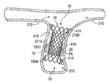
하나의 예시적인 실시예에서, 의료 디바이스용 도킹 스테이션은 프레임, 복수의 방사선 불투과성 마커(radiopaque marker), 및 불투과성 재료를 포함한다. 프레임은 근위 단부로부터 원위 단부로 연장되는 복수의 스트러트를 갖는다. 스트러트는 복수의 셀과 판막 시트를 정의한다. 방사선 불투과성 마커는 판막 시트 둘레에 배치된다. 불투과성 재료는 프레임에 부착된다.In one exemplary embodiment, a docking station for a medical device includes a frame, a plurality of radiopaque markers, and an opaque material. The frame has a plurality of struts extending from the proximal end to the distal end. The strut defines a plurality of cells and valve sheets. A radiopaque marker is placed around the valve sheet. An impervious material is attached to the frame.
하나의 예시적인 실시예에서, 시스템은 튜브 및 도킹 스테이션 프레임을 포함한다. 튜브는 하나 이상의 방사선 불투과성 마커를 갖는다. 도킹 스테이션 프레임은 튜브에 배치된다. 도킹 스테이션은 하나 이상의 방사선 불투과성 마커를 포함한다. 튜브의 방사선 불투과성 마커에 대한 도킹 스테이션의 하나 이상의 방사선 불투과성 마커의 위치는 튜브로부터 도킹 스테이션의 전개량을 나타낸다.In one exemplary embodiment, a system includes a tube and a docking station frame. The tube has one or more radiopaque markers. The docking station frame is placed on the tube. The docking station includes one or more radiopaque markers. The position of the one or more radiopaque markers of the docking station relative to the radiopaque marker of the tube indicates the amount of deployment of the docking station from the tube.
도킹 스테이션 프레임을 전개하는 하나의 예시적인 방법에서, 도킹 스테이션 프레임의 방사선 불투과성 마커는 도킹 스테이션 프레임의 판막 시트의 전개를 위한 목표 위치에 위치 설정된다. 도킹 스테이션 프레임의 일부는 튜브로부터 전개되어, 튜브의 방사선 불투과성 마커가 도킹 스테이션 프레임의 방사선 불투과성 마커와 실질적으로 정렬되게 된다. 튜브의 방사선 불투과성 마커와 도킹 스테이션 프레임의 방사선 불투과성 마커는 시각적으로 목표 위치에 있음을 확인한다. 도킹 스테이션 프레임이 추가로 전개되어 튜브로부터 해제된다.In one exemplary method of deploying the docking station frame, a radiopaque marker of the docking station frame is positioned at a target location for deployment of the valve sheet of the docking station frame. A portion of the docking station frame is deployed from the tube such that the radiopaque markers on the tube are substantially aligned with the radiopaque markers on the docking station frame. A radiopaque marker on the tube and a radiopaque marker on the docking station frame visually confirm that it is in the target position. The docking station frame is further deployed and released from the tube.
하나의 예시적인 실시예에서, 시스템은 전달 카테터 조립체 및 도킹 스테이션 프레임을 포함한다. 전달 카테터 조립체는 외부 튜브와 연결 튜브를 포함한다. 외부 튜브는 원위 단부 및 원위 단부에 또는 그 근방에 배치된 하나 이상의 방사선 불투과성 마커를 갖는다. 연결 튜브는 외부 튜브에 배치된 하나 이상의 방사선 불투과성 마커를 갖는다. 도킹 스테이션 프레임은 외부 튜브에 배치되고 연결 튜브에 결합된다. 도킹 스테이션 프레임은 연결 튜브 및 도킹 스테이션 프레임에 대해 근위 방향으로 외부 튜브를 후퇴시킴으로써 전개된다. 외부 튜브의 방사선 불투과성 마커에 대한 연결 튜브의 하나 이상의 방사선 불투과성 마커의 위치는 외부 튜브로부터 도킹 스테이션의 전개량을 나타낸다.In one exemplary embodiment, a system includes a delivery catheter assembly and a docking station frame. The delivery catheter assembly includes an outer tube and a connecting tube. The outer tube has a distal end and one or more radiopaque markers disposed at or near the distal end. The connecting tube has one or more radiopaque markers disposed on the outer tube. The docking station frame is placed on the outer tube and coupled to the connecting tube. The docking station frame is deployed by retracting the outer tube proximally relative to the connecting tube and docking station frame. The position of the at least one radiopaque marker on the connecting tube relative to the radiopaque marker on the outer tube indicates the amount of deployment of the docking station from the outer tube.
도킹 스테이션 프레임을 전개하는 하나의 예시적인 방법에서, 도킹 스테이션 프레임의 일부는 외부 튜브의 방사선 불투과성 마커가 연결 튜브의 방사선 불투과성 마커에 더 근접하게 이동하도록 연결 튜브와 함께 외부 튜브로부터 전개된다. 외부 튜브의 방사선 불투과성 마커와 연결 튜브의 방사선 불투과성 마커의 정렬은 도킹 스테이션 프레임이 외부 튜브에 의해 재포획될 수 있는 최종 지점을 나타낸다.In one exemplary method of deploying the docking station frame, a portion of the docking station frame is deployed from the outer tube along with the connecting tube such that the radiopaque marker on the outer tube moves closer to the radiopaque marker on the connecting tube. The alignment of the radiopaque marker of the outer tube with the radiopaque marker of the connecting tube represents the final point at which the docking station frame can be recaptured by the outer tube.
하나의 예시적인 실시예에서, 시스템은 전달 카테터 조립체 및 도킹 스테이션 프레임을 포함한다. 전달 카테터 조립체는 세장형 노즈콘, 외부 튜브, 도킹 스테이션 커넥터, 및 연결 튜브를 포함한다. 외부 튜브는 원위 단부 및 원위 단부에 또는 그 근방에 배치된 하나 이상의 방사선 불투과성 마커를 갖는다. 도킹 스테이션 커넥터는 외부 튜브 내에서 이동 가능하다. 연결 튜브는 외부 튜브에 배치된다. 연결 튜브는 세장형 노즈콘과 도킹 스테이션 커넥터 사이에 배치된 하나 이상의 방사선 불투과성 마커를 포함한다. 도킹 스테이션 프레임은 외부 튜브에 배치되고 도킹 스테이션 커넥터에 결합된다. 도킹 스테이션 프레임은 하나 이상의 방사선 불투과성 마커를 포함한다. 도킹 스테이션 프레임은 세장형 노즈콘으로부터 근위 방향으로 외부 튜브를 후퇴시킴으로써 전개된다. 외부 튜브의 방사선 불투과성 마커, 연결 튜브의 방사선 불투과성 마커, 및 도킹 스테이션 프레임의 방사선 불투과성 마커는 도킹 스테이션 프레임의 올바른 배치 및 도킹 스테이션 프레임이 외부 튜브에 의해 재포획될 수 있는 최종 지점 중 하나 이상을 시각적으로 결정하도록 구성된다.In one exemplary embodiment, a system includes a delivery catheter assembly and a docking station frame. The delivery catheter assembly includes an elongate nose cone, an outer tube, a docking station connector, and a connecting tube. The outer tube has a distal end and one or more radiopaque markers disposed at or near the distal end. The docking station connector is movable within the outer tube. A connecting tube is placed on the outer tube. The connecting tube includes one or more radiopaque markers disposed between the elongated nose cone and the docking station connector. The docking station frame is placed on the outer tube and coupled to the docking station connector. The docking station frame includes one or more radiopaque markers. The docking station frame is deployed by retracting the outer tube proximally from the elongated nose cone. The radiopaque markers on the outer tubes, the radiopaque markers on the connecting tubes, and the radiopaque markers on the docking station frame are one of the correct placement of the docking station frame and the final point at which the docking station frame can be recaptured by the outer tubes. It is configured to visually determine anomalies.
하나의 예시적인 실시예에서, 조립체는 프레임, 세장형 노즈콘, 외부 튜브, 도킹 스테이션 커넥터, 및 연결 튜브를 포함한다. 프레임은 판막 시트 및 판막 시트 둘레에 배치된 복수의 방사선 불투과성 마커를 갖는다. 외부 튜브는 원위 단부 및 원위 단부 근방에 배치된 하나 이상의 방사선 불투과성 마커를 갖는다. 도킹 스테이션 커넥터는 외부 튜브 내에서 이동 가능하다. 연결 튜브는 세장형 노즈콘과 도킹 스테이션 커넥터 사이에 배치된다. 프레임은 세장형 노즈콘으로부터 근위 방향으로 외부 튜브를 후퇴시킴으로써 전개된다.In one exemplary embodiment, an assembly includes a frame, an elongated nose cone, an outer tube, a docking station connector, and a connecting tube. The frame has a valve sheet and a plurality of radiopaque markers disposed around the valve sheet. The outer tube has a distal end and one or more radiopaque markers disposed proximate the distal end. The docking station connector is movable within the outer tube. A connecting tube is placed between the elongated nose cone and the docking station connector. The frame is deployed by retracting the outer tube proximally from the elongated nose cone.
본 명세서에 설명된 다양한 실시예 및 방법은 의료 및 훈련 시술을 포함하는(이에 제한되지 않음) 다양한 시술에서 피검자 내에서 이용될 수 있다. 피검자는 의료 환자, 수의학 환자, 동물 모델, 시체, 심장 및 혈관 구조 시스템의 시뮬레이터(예를 들어, 의인화된 팬텀 및 체외이식 조직)를 포함한다(단, 이에 제한되지 않음).The various embodiments and methods described herein may be used within a subject in a variety of procedures including, but not limited to, medical and training procedures. Subjects include, but are not limited to, medical patients, veterinary patients, animal models, cadavers, simulators of cardiac and vasculature systems (eg, anthropomorphic phantoms and explanted tissue).
본 개시내용의 다른 장소에서 설명된 바와 같은 다양한 특징이 여기서 요약된 예에 포함될 수 있고, 본 명세서의 다른 장소에서 설명된 것을 포함하여 예 및 특징을 사용하기 위한 다양한 방법 및 단계가 사용될 수 있다.Various features as described elsewhere in this disclosure may be included in the examples summarized herein, and various methods and steps for using the examples and features may be used, including those described elsewhere in this specification.
개시된 발명의 특성 및 이점의 추가 이해는 특히 동일한 부분이 동일한 참조 번호를 갖는 첨부 도면과 관련하여 고려될 때 이하의 설명 및 청구범위로부터 얻어질 수 있다.A further understanding of the features and advantages of the disclosed invention may be obtained from the following description and claims, especially when considered in connection with the accompanying drawings in which like parts have like reference numerals.
본 개시내용의 실시예의 다양한 양태를 더 명확하게 하기 위해, 특정 실시예의 보다 구체적인 설명은 첨부 도면의 다양한 양태를 참조하여 이루어질 것이다. 이들 도면은 본 개시내용의 통상적인 실시예만을 도시하고, 그에 따라 본 개시내용의 범위를 제한하는 것으로 고려되어서는 안된다는 것이 이해된다. 더욱이, 도면은 일부 실시예에 대해 실척으로 작성될 수 있지만, 모든 실시예에 대해 도면이 반드시 실척으로 작성되지는 않는다. 본 개시내용의 실시예는 첨부 도면의 사용을 통해 추가로 구체적이고 상세하게 묘사되고 설명될 것이다.
도 1a는 확장기 페이즈의 인간 심장의 절취도이고;
도 1b는 수축기 페이즈의 인간 심장의 절취도이며;
도 2a 내지 도 2e는 폐동맥이 다양한 상이한 형상 및 크기를 가질 수 있음을 예시하는 폐동맥의 단면도이고;
도 3a 내지 도 3d는 폐동맥이 다양한 상이한 형상 및 크기를 가질 수 있음을 예시하는 폐동맥의 사시도이며;
도 4a는 순환계에 위치 설정되는 압축된 도킹 스테이션의 개략도이고;
도 4b는 순환계에서 도킹 스테이션의 위치를 설정하도록 팽창된 도 4a의 도킹 스테이션의 개략도이며;
도 4c는 도 4b에 의해 예시된 도킹 스테이션에 위치 설정되는 팽창 가능한 카테터경유 심장 판막의 개략도이고;
도 4d는 도킹 스테이션에서 심장 판막의 위치를 설정하기 위해 팽창된 도 4c의 카테터경유 심장 판막의 개략도이며;
도 4e는 순환계의 불규칙한 형상 부분 내에서 전개된 도킹 스테이션 및 카테터경유 심장 판막을 예시하고;
도 4f는 폐동맥 내에서 전개된 도킹 스테이션 및 카테터경유 심장 판막을 예시하며;
도 5a는 순환계에 위치 설정되는 압축된 도킹 스테이션의 개략도이고;
도 5b는 순환계에서 도킹 스테이션의 위치를 설정하도록 팽창된 도 5a의 도킹 스테이션의 개략도이며;
도 5c는 도 5b에 의해 예시된 도킹 스테이션에 위치 설정되는 팽창 가능한 카테터경유 심장 판막의 개략도이고;
도 5d는 도킹 스테이션에서 심장 판막의 위치를 설정하기 위해 팽창된 도 5c의 카테터경유 심장 판막의 개략도이며;
도 5e는 순환계의 불규칙한 형상 부분 내에서 전개된 도킹 스테이션 및 카테터경유 심장 판막을 예시하고;
도 5f는 폐동맥 내에서 전개된 도킹 스테이션 및 카테터경유 심장 판막을 예시하며;
도 6a는 도킹 스테이션이 폐동맥 내에서 전개된 수축기 페이즈에서 인간 심장의 절취도이고;
도 6b는 도킹 스테이션 및 카테터경유 심장 판막이 폐동맥 내에서 전개된 수축기 페이즈에서 인간 심장의 절취도이며;
도 7a는 심장이 수축기 페이즈에 있을 때 도 6b의 도킹 스테이션 및 카테터경유 심장 판막의 확대 개략도이고;
도 7b는 도 7a의 라인 7B-7B로 표시된 방향에서 취한 도면이며;
도 7c는 도킹 스테이션 직경과 도킹 스테이션에 의해 인가되는 반경방향 외향력 사이의 관계를 도시하고 있는 그래프이고;
도 8은 도킹 스테이션 및 카테터경유 심장 판막이 폐동맥 내에서 전개된 확장기 페이즈에서 인간 심장의 절취도이며;
도 9a는 심장이 확장기 페이즈에 있을 때 도 8의 도킹 스테이션 및 카테터경유 심장 판막의 확대 개략도이고;
도 9b는 도 9a의 라인 9B-9B로 표시된 방향에서 취한 도면이며;
도 10a는 카테터경유 심장 판막이 도킹 스테이션 내부에 배치된 도킹 스테이션의 예시적인 실시예를 예시하고;
도 10b는 카테터경유 심장 판막이 도킹 스테이션 내부에 배치된 도킹 스테이션의 예시적인 실시예를 예시하며;
도 10c는 카테터경유 심장 판막이 도킹 스테이션 내부에 배치된 도킹 스테이션의 예시적인 실시예를 예시하고;
도 10d는 카테터경유 심장 판막이 도킹 스테이션 내부에 배치된 도킹 스테이션의 예시적인 실시예를 예시하며;
도 11a는 신축식 도킹 스테이션의 예시적인 실시예를 예시하고;
도 11b는 신축식 도킹 스테이션의 예시적인 실시예를 예시하며;
도 11c는 신축식 도킹 스테이션의 예시적인 실시예를 예시하고;
도 11d는 신축식 도킹 스테이션의 예시적인 실시예를 예시하며;
도 12a는 카테터경유 심장 판막이 도킹 스테이션 내부에 배치된 도킹 스테이션의 예시적인 실시예를 예시하고;
도 12b는 카테터경유 심장 판막이 도킹 스테이션 내부에 배치된 도킹 스테이션의 예시적인 실시예를 예시하며;
도 12c는 카테터경유 심장 판막이 도킹 스테이션 내부에 배치된 도킹 스테이션의 예시적인 실시예를 예시하고;
도 12d는 카테터경유 심장 판막이 도킹 스테이션 내부에 배치된 도킹 스테이션의 예시적인 실시예를 예시하며;
도 13a는 신축식 도킹 스테이션의 예시적인 실시예를 예시하고;
도 13b는 신축식 도킹 스테이션의 예시적인 실시예를 예시하며;
도 13c는 신축식 도킹 스테이션의 예시적인 실시예를 예시하고;
도 13d는 신축식 도킹 스테이션의 예시적인 실시예를 예시하며;
도 14a는 카테터경유 심장 판막이 도킹 스테이션 내부에 배치된 도킹 스테이션의 예시적인 실시예를 예시하고;
도 14b는 카테터경유 심장 판막이 도킹 스테이션 내부에 배치된 도킹 스테이션의 예시적인 실시예를 예시하며;
도 14c는 카테터경유 심장 판막이 도킹 스테이션 내부에 배치된 도킹 스테이션의 예시적인 실시예를 예시하고;
도 14d는 카테터경유 심장 판막이 도킹 스테이션 내부에 배치된 도킹 스테이션의 예시적인 실시예를 예시하며;
도 14e는 카테터경유 심장 판막이 도킹 스테이션 내부에 배치된 도킹 스테이션의 예시적인 실시예를 예시하고;
도 14f는 카테터경유 심장 판막이 도킹 스테이션 내부에 배치된 도킹 스테이션의 예시적인 실시예를 예시하며;
도 14g는 카테터경유 심장 판막이 도킹 스테이션 내부에 배치된 도킹 스테이션의 예시적인 실시예를 예시하고;
도 15a는 도킹 스테이션의 프레임의 예시적인 실시예의 측면도이며;
도 15b는 도 15a에 의해 예시된 프레임의 측면 프로파일을 예시하고;
도 16은 압축된 상태에서 도 15a의 도킹 스테이션 프레임을 예시하며;
도 17a는 도 15a의 도킹 스테이션 프레임의 사시도이고;
도 17b는 도 15a의 도킹 스테이션 프레임의 사시도이며;
도 18은 복수의 커버된 셀 및 복수의 개방 셀을 갖는 도킹 스테이션의 예시적인 실시예의 사시도이고;
도 19는 도킹 스테이션에서 제자리로 팽창된 카테터경유 심장 판막을 예시하기 위해 일부가 절취된 도 18에 의해 예시된 도킹 스테이션의 사시도이며;
도 20은 순환계의 혈관에 이식될 때 도 18에 의해 예시된 도킹 스테이션의 측면 프로파일을 예시하고;
도 21은 순환계의 혈관에 설치될 때 도 18에 의해 예시된 도킹 스테이션의 사시도를 예시하며;
도 22는 순환계의 혈관에 이식될 때 도 19에 의해 예시된 도킹 스테이션 및 판막의 사시도를 예시하고;
도 23a 및 도 23b는 순환계의 상이한 크기의 혈관에 이식될 때 도 18에 의해 예시된 도킹 스테이션의 측면 프로파일을 예시하며;
도 24 및 도 25는 순환계의 상이한 크기의 혈관에 이식될 때 도 18에 의해 예시된 도킹 스테이션의 측면 프로파일을 예시하는데, 개략적으로 예시된 카테터경유 심장 판막은 각각의 도킹 스테이션에 설치되거나 전개된 동일한 크기를 갖고;
도 26a는 폐동맥 내에 배치된 도킹 스테이션의 예시적인 실시예의 측면 프로파일을 예시하는 단면도이며;
도 26b는 폐동맥 내에 배치된 도킹 스테이션 및 도킹 스테이션 내에 배치된 개략적으로 예시된 판막의 예시적인 실시예의 측면 프로파일을 예시하는 단면도이고;
도 26c는 폐동맥 내에 배치된 도킹 스테이션 및 도킹 스테이션 내에 배치된 판막의 예시적인 실시예를 예시하는 단면도이며;
도 27은 도킹 스테이션의 예시적인 실시예의 측면도이고;
도 28은 신축식 도킹 스테이션의 예시적인 실시예의 측면도이며;
도 29는 도킹 스테이션의 2개의 부분이 함께 텔레스코핑된 도 28의 도킹 스테이션의 측면도이고;
도 30은 폐동맥 내에 배치된 도킹 스테이션을 예시하는 단면도이며;
도 31a는 폐동맥 내에 배치된 도킹 스테이션의 예시적인 실시예의 측면 프로파일을 예시하는 단면도이고;
도 31b는 폐동맥 내에 배치된 도킹 스테이션 및 도킹 스테이션 내에 배치된 판막의 예시적인 실시예의 측면 프로파일을 예시하는 단면도이며;
도 32a는 도킹 스테이션이 폐동맥 내에서 전개된 수축기 페이즈에서 인간 심장의 절취도이고;
도 32b는 도킹 스테이션 및 카테터경유 심장 판막이 폐동맥 내에서 전개된 수축기 페이즈에서 인간 심장의 절취도이며;
도 33a는 심장이 수축기 페이즈에 있을 때 도 32b의 도킹 스테이션 및 카테터경유 심장 판막의 확대 개략도이고;
도 33b는 도 33a의 라인 33B-33B로 표시된 방향에서 취한 도면이며;
도 34는 심장이 확장기 페이즈에 있을 때 도 32b에 의해 예시된 폐동맥 내에서 전개된 인간 심장, 도킹 스테이션, 및 카테터경유 심장 판막의 절취도이고;
도 35a는 심장이 확장기 페이즈에 있을 때 도 34의 도킹 스테이션 및 카테터경유 심장 판막의 확대 개략도이며;
도 35b는 도 35a의 라인 35B-35B로 표시된 방향에서 취한 도면이고;
도 36a는 도킹 스테이션이 폐동맥 내에서 전개되는 수축기 페이즈에서 인간 심장의 절취도이며;
도 36b는 도킹 스테이션이 폐동맥 내에서 전개된 수축기 페이즈에서 인간 심장의 절취도이고;
도 36c는 도킹 스테이션 및 카테터경유 심장 판막이 폐동맥 내에서 전개된 수축기 페이즈에서 인간 심장의 절취도이며;
도 37a는 심장이 수축기 페이즈에 있을 때 도 36c의 도킹 스테이션 및 카테터경유 심장 판막의 확대 개략도이고;
도 37b는 도 37a의 라인 37B-37B로 표시된 방향에서 취한 도면이며;
도 38은 심장이 확장기 페이즈에 있을 때 도 36c에 의해 예시된 폐동맥 내에서 전개된 인간 심장, 도킹 스테이션, 및 카테터경유 심장 판막의 절취도이고;
도 39a는 심장이 확장기 페이즈에 있을 때 도 38의 도킹 스테이션 및 카테터경유 심장 판막의 확대 개략도이며;
도 39b는 도 39a의 라인 39B-39B로 표시된 방향에서 취한 도면이고;
도 40a는 도킹 스테이션이 폐동맥 내에서 전개되는 수축기 페이즈에서 인간 심장의 절취도이며;
도 40b는 도킹 스테이션이 폐동맥 내에서 전개된 수축기 페이즈에서 인간 심장의 절취도이고;
도 40c는 도킹 스테이션 및 카테터경유 심장 판막이 폐동맥 내에서 전개된 수축기 페이즈에서 인간 심장의 절취도이며;
도 41a는 심장이 수축기 페이즈에 있을 때 도 40c의 도킹 스테이션 및 카테터경유 심장 판막의 확대 개략도이고;
도 41b는 도 41a의 라인 41B-41B로 표시된 방향에서 취한 도면이며;
도 42는 심장이 확장기 페이즈에 있을 때 도 40c에 의해 예시된 폐동맥 내에서 전개된 인간 심장, 도킹 스테이션, 및 카테터경유 심장 판막의 절취도이고;
도 43a는 심장이 확장기 페이즈에 있을 때 도 42의 도킹 스테이션 및 카테터경유 심장 판막의 확대 개략도이며;
도 43b는 도 43a의 라인 43B-43B로 표시된 방향에서 취한 도면이고;
도 44 내지 도 47, 및 도 48a 내지 도 48c는 도킹 스테이션, 예를 들어, 본 명세서에 설명되거나 도시되어 있는 도킹 스테이션 중 하나에서 전개될 수 있는 판막 유형의 예를 예시하며;
도 49a는 카테터의 예시적인 실시예의 단면도이고;
도 49b는 도킹 스테이션이 크림핑되고 카테터에 로딩된 카테터의 예시적인 실시예의 단면도이며;
도 50a 내지 도 50d는 카테터로부터 도킹 스테이션의 전개를 예시하고;
도 51은 카테터의 노즈콘의 예시적인 실시예의 측면도이며;
도 52는 도 51의 선 52-52로 표시된 바와 같이 취한 도면이고;
도 53은 카테터의 원위 부분의 예시적인 실시예의 단면도이며;
도 54는 카테터의 노즈콘의 예시적인 실시예의 측면도이고;
도 55는 카테터의 원위 부분의 예시적인 실시예의 단면도이며;
도 56은 카테터에 도킹 스테이션을 유지하기 위한 홀더의 사시도이고;
도 57은 카테터에 도킹 스테이션을 유지하기 위한 홀더의 사시도이며;
도 57a 및 도 57b는 홀더에 배치된 도킹 스테이션의 연장부의 측면도를 예시하고;
도 58은 도킹 스테이션 카테터용 핸들의 예시적인 실시예의 단면도이며;
도 59는 도 58의 핸들의 부분의 분해 사시도이고;
도 60은 도 58의 핸들의 부분의 분해 단면도이며;
도 61은 도 58의 핸들의 부분의 분해 사시 단면도이고;
도 62는 측면 커버가 제거된 도킹 스테이션 카테터용 핸들의 예시적인 실시예의 도면이며;
도 63은 카테터의 플러싱 시스템을 예시하는 도 62의 확대 부분이고;
도 64a 및 도 64b는 도킹 스테이션 카테터의 외부 슬리브의 연장 및 후퇴를 예시하기 위해 대향 측면 커버가 제거된 도 62에 의해 예시된 핸들의 도면이며;
도 65는 도 62의 핸들의 분해도이고;
도 66은 대향 측면 커버가 제거된 도 62에 의해 예시된 핸들의 사시도이며;
도 67은 도 62에 의해 예시된 핸들의 측면도이고;
도 68은 래칫 상태에 있는 도 62에 의해 예시된 핸들의 인덱싱 휠의 측면도이며;
도 69는 래칫 상태에 있는 도 68의 인덱싱 휠의 사시도이고;
도 70은 도 69의 확대 부분이며;
도 71은 핸들 하우징에 배치된 도 68에 의해 예시된 인덱싱 휠의 부분 단면도이고;
도 72는 맞물림 해제 상태에 있는 도 71과 유사한 도면이며;
도 73은 맞물림 해제 상태에 있는 도 62에 의해 예시된 핸들의 인덱싱 휠의 측면도이고;
도 74는 도킹 스테이션의 프레임의 일 실시예의 측면도이며;
도 75는 도킹 스테이션의 프레임의 다른 실시예의 측면도이고;
도 76a는 도킹 스테이션의 프레임의 일 실시예의 측면도이며;
도 76b는 도 76a의 프레임의 저면도이고;
도 76c는 도 76a의 프레임의 평면도이며;
도 77a는 도킹 스테이션의 프레임의 다른 실시예의 측면도이고;
도 77b는 도 77a의 프레임의 저면도이며;
도 77c는 도 77a의 프레임의 평면도이고;
도 78a는 유출 셀을 갖는 도킹 스테이션의 일 실시예의 측면도이며;
도 78b는 도 78a의 도킹 스테이션의 평면도이고;
도 79는 유출 셀을 갖는 도킹 스테이션의 다른 실시예의 측면도이며;
도 80a는 일 실시예의 도킹 스테이션의 프레임의 측면도이고;
도 80b는 다른 실시예의 도킹 스테이션의 프레임의 측면도이며;
도 80c는 다른 실시예의 도킹 스테이션의 프레임의 측면도이고;
도 81a는 일 실시예에 따른 프레임 및 불투과성 재료를 갖는 도킹 스테이션의 측면도이며;
도 81b는 다른 실시예에 따른 프레임 및 불투과성 재료를 갖는 도킹 스테이션의 측면도이고;
도 81c는 다른 실시예에 따른 프레임 및 불투과성 재료를 갖는 도킹 스테이션의 측면도이며;
도 81d는 다른 실시예에 따른 프레임 및 불투과성 재료를 갖는 도킹 스테이션의 측면도이고;
도 82a는 근위 부분 및 원위 부분을 갖는 불투과성 재료의 상부 구성요소이며;
도 82b는 도 82a의 불투과성 재료의 조립된 근위 부분의 측면 사시도이고;
도 82c는 도 82a의 불투과성 재료의 조립된 근위 부분의 상부 사시도이며;
도 82d는 도 82a의 불투과성 재료의 조립된 원위 부분의 측면 사시도이고;
도 82e 내지 도 82i는 도 82a의 불투과성 재료의 조립체의 측면 사시도이며;
도 82j는 일 실시예에 따른 천에 윤곽 형성된 도 82a의 근위 부분 및 원위 부분의 개략적인 평면도이고;
도 82k는 다른 실시예에 따른 천에 윤곽 형성된 도 82a의 근위 부분 및 원위 부분의 개략적인 평면도이며;
도 83은 일 실시예의 프레임 내에 배치된 일 실시예의 불투과성 재료의 측면도이고;
도 84a 내지 도 84i는 도 83의 불투과성 재료와 프레임을 서로 고정하는 한 가지 방법을 예시하며;
도 85a 내지 도 85e는 도 83의 불투과성 재료와 프레임을 서로 고정하는 또 다른 방법을 예시하고;
도 86a는 일 실시예에 따른 방사선 불투과성 마커의 측면 사시도이며;
도 86b는 다른 실시예에 따른 방사선 불투과성 마커의 측면 사시도이고;
도 86c는 다른 실시예에 따른 방사선 불투과성 마커의 측면 사시도이며;
도 86d는 다른 실시예에 따른 방사선 불투과성 마커의 측면 사시도이고;
도 87a는 일 실시예에 따른 마커 설정을 갖는 프레임의 측면 사시도이며;
도 87b는 다른 실시예에 따른 마커 설정을 갖는 프레임의 측면 사시도이고;
도 87c는 다른 실시예에 따른 마커 설정을 갖는 프레임의 측면 사시도이며;
도 88은 마커 설정에 배치된 방사선 불투과성 마커의 개략도이고;
도 89a는 일 실시예에 따른 방사선 불투과성 마커를 갖는 불투과성 재료의 사시도이며;
도 89b는 포켓 내에 배치된 방사선 불투과성 마커를 갖는 불투과성 재료의 측면도이고;
도 89c는 일 실시예에 따른 불투과성 재료의 포켓 위에 배치된 포켓 커버링의 개략도이며;
도 89d는 다른 실시예에 따른 불투과성 재료의 포켓 위에 배치된 포켓 커버링의 개략도이고;
도 89e 내지 도 89h는 포켓 및 방사선 불투과성 마커를 불투과성 부재에 고정하는 방법을 예시하며;
도 89i는 일 실시예에 따른 도 89e 내지 도 89h의 방법의 추가 단계를 예시하고;
도 89j는 다른 실시예에 따른 도 89e 내지 도 89h의 방법의 추가 단계를 예시하며;
도 89k는 다른 실시예에 따른 도 89e 내지 도 89h의 방법의 추가 단계를 예시하고;
도 89l은 다른 실시예에 따른 도 89e 내지 도 89h의 방법의 추가 단계를 예시하며;
도 89m은 다른 실시예에 따른 도 89e 내지 도 89h의 방법의 추가 단계를 예시하고;
도 89n은 다른 실시예에 따른 도 89e 내지 도 89h의 방법의 추가 단계를 예시하며;
도 90a는 일 실시예에 따른 방사선 불투과성 마커를 갖는 프레임의 측면도이고;
도 90b는 다른 실시예에 따른 방사선 불투과성 마커를 갖는 프레임의 측면도이며;
도 90c는 다른 실시예에 따른 방사선 불투과성 마커를 갖는 프레임의 측면도이고;
도 91은 방사선 불투과성 마커를 갖는 프레임에 위치 설정된 팽창 가능한 카테터경유 심장 판막의 개략도이며;
도 92a는 일 실시예에 따른 방사선 불투과성 마커를 갖는 노즈콘과 외부 튜브의 사시도이고;
도 92b는 도 92a의 노즈콘과 외부 튜브의 부분 절취 사시도이며;
도 92c는 또 다른 실시예에 따른 복수의 방사선 불투과성 마커를 갖는 사시 노즈콘 및 외부 튜브이고;
도 93a 내지 도 93c는 도킹 스테이션 프레임이 없는 전달 카테터 조립체의 전개를 예시하며;
도 94는 방사선 불투과성 마커 및 도킹 스테이션이 크림핑되고 카테터에 로딩된 카테터의 예시적인 실시예의 부분 절취 단면도이고;
도 95a 내지 도 95c는 방사선 불투과성 마커를 갖는 카테터로부터 방사선 불투과성 마커를 갖는 도킹 스테이션의 전개를 예시하며;
도 96a 및 도 96b는 형광 투시법 하에 볼 때 방사선 불투과성 마커를 갖는 카테터로부터 방사선 불투과성 마커를 갖는 도킹 스테이션의 전개를 예시한다.In order to make various aspects of embodiments of the present disclosure more clear, more specific descriptions of specific embodiments will be made with reference to various aspects of the accompanying drawings. It is understood that these drawings depict only typical embodiments of the present disclosure and, as such, should not be considered limiting the scope of the present disclosure. Moreover, while the drawings may be drawn to scale for some embodiments, the drawings are not necessarily drawn to scale for all embodiments. Embodiments of the present disclosure will be depicted and described in further specificity and detail through the use of the accompanying drawings.
1A is a cutaway view of a human heart in diastolic phase;
1B is a cutaway view of a human heart in the systolic phase;
2A-2E are cross-sectional views of the pulmonary artery illustrating that the pulmonary artery can have a variety of different shapes and sizes;
3A-3D are perspective views of the pulmonary artery illustrating that the pulmonary artery can have a variety of different shapes and sizes;
4A is a schematic diagram of a compressed docking station positioned in the circulatory system;
Figure 4b is a schematic diagram of the docking station of Figure 4a inflated to establish its position in the circulatory system;
Fig. 4C is a schematic diagram of a heart valve via an expandable catheter positioned in the docking station illustrated by Fig. 4B;
Figure 4d is a schematic diagram of the transcatheterized heart valve of Figure 4c inflated to position the heart valve in a docking station;
4e illustrates a docking station and transcatheter heart valve deployed within an irregularly shaped portion of the circulatory system;
4F illustrates a docking station and transcatheter heart valve deployed within a pulmonary artery;
5A is a schematic diagram of a compressed docking station positioned in the circulatory system;
Fig. 5B is a schematic diagram of the docking station of Fig. 5A inflated to establish the position of the docking station in the circulatory system;
Fig. 5C is a schematic diagram of a heart valve via an expandable catheter positioned in the docking station illustrated by Fig. 5B;
Fig. 5d is a schematic diagram of the transcatheterized heart valve of Fig. 5c inflated to position the heart valve in a docking station;
5E illustrates a docking station and transcatheter heart valve deployed within an irregularly shaped portion of the circulatory system;
5F illustrates a docking station and transcatheter heart valve deployed within a pulmonary artery;
6A is a cutaway view of a human heart in the systolic phase with the docking station deployed within the pulmonary artery;
6B is a cutaway view of a human heart in the systolic phase with a docking station and catheterized heart valve deployed within the pulmonary artery;
Fig. 7A is an enlarged schematic diagram of the docking station and transcatheter heart valve of Fig. 6B when the heart is in the systolic phase;
Fig. 7B is a view taken in the direction indicated by line 7B-7B in Fig. 7A;
7C is a graph illustrating the relationship between docking station diameter and radial outward force applied by the docking station;
8 is a cutaway view of a human heart in diastolic phase with docking station and catheterized heart valves deployed within the pulmonary artery;
Fig. 9A is an enlarged schematic diagram of the docking station and transcatheter heart valve of Fig. 8 when the heart is in diastolic phase;
Fig. 9B is a view taken in the direction indicated by line 9B-9B in Fig. 9A;
10A illustrates an exemplary embodiment of a docking station in which a catheterized heart valve is disposed within the docking station;
10B illustrates an exemplary embodiment of a docking station in which a catheterized heart valve is disposed within the docking station;
10C illustrates an exemplary embodiment of a docking station in which a catheterized heart valve is disposed within the docking station;
10D illustrates an exemplary embodiment of a docking station in which a catheterized heart valve is disposed within the docking station;
11A illustrates an exemplary embodiment of a telescoping docking station;
11B illustrates an example embodiment of a telescoping docking station;
11C illustrates an example embodiment of a telescoping docking station;
11D illustrates an example embodiment of a telescoping docking station;
12A illustrates an exemplary embodiment of a docking station in which a catheterized heart valve is disposed within the docking station;
12B illustrates an exemplary embodiment of a docking station in which a catheterized heart valve is disposed within the docking station;
12C illustrates an exemplary embodiment of a docking station in which a catheterized heart valve is disposed within the docking station;
12D illustrates an exemplary embodiment of a docking station in which a catheterized heart valve is disposed within the docking station;
13A illustrates an example embodiment of a telescoping docking station;
13B illustrates an example embodiment of a telescoping docking station;
13C illustrates an example embodiment of a telescoping docking station;
13D illustrates an example embodiment of a telescoping docking station;
14A illustrates an example embodiment of a docking station in which a catheterized heart valve is disposed within the docking station;
14B illustrates an exemplary embodiment of a docking station in which a catheterized heart valve is disposed within the docking station;
14C illustrates an example embodiment of a docking station in which a catheterized heart valve is disposed within the docking station;
14D illustrates an exemplary embodiment of a docking station in which a catheterized heart valve is disposed within the docking station;
14E illustrates an exemplary embodiment of a docking station in which a catheterized heart valve is disposed within the docking station;
14F illustrates an exemplary embodiment of a docking station with a catheterized heart valve disposed within the docking station;
14G illustrates an exemplary embodiment of a docking station in which a catheterized heart valve is disposed within the docking station;
15A is a side view of an exemplary embodiment of a frame of a docking station;
Fig. 15B illustrates a side profile of the frame illustrated by Fig. 15A;
Fig. 16 illustrates the docking station frame of Fig. 15A in a compressed state;
Fig. 17A is a perspective view of the docking station frame of Fig. 15A;
Fig. 17B is a perspective view of the docking station frame of Fig. 15A;
18 is a perspective view of an exemplary embodiment of a docking station having a plurality of covered cells and a plurality of open cells;
Fig. 19 is a perspective view of the docking station illustrated by Fig. 18 with portions cut away to illustrate a transcatheterized heart valve inflated in place at the docking station;
Fig. 20 illustrates a side profile of the docking station illustrated by Fig. 18 when implanted into a blood vessel of the circulatory system;
Fig. 21 illustrates a perspective view of the docking station illustrated by Fig. 18 when installed in a blood vessel of the circulatory system;
Fig. 22 illustrates a perspective view of the docking station and valve illustrated by Fig. 19 when implanted in a blood vessel of the circulatory system;
23A and 23B illustrate side profiles of the docking station illustrated by FIG. 18 when implanted into different sized blood vessels of the circulatory system;
24 and 25 illustrate side profiles of the docking station illustrated by FIG. 18 when implanted into different sized vessels of the circulatory system, the transcatheterized heart valve schematically illustrated being the same installed or deployed in each docking station. have a size;
26A is a cross-sectional view illustrating a side profile of an exemplary embodiment of a docking station disposed within a pulmonary artery;
26B is a cross-sectional view illustrating a side profile of an exemplary embodiment of a docking station disposed within a pulmonary artery and a schematically illustrated valve disposed within the docking station;
26C is a cross-sectional view illustrating an exemplary embodiment of a docking station disposed within a pulmonary artery and a valve disposed within the docking station;
27 is a side view of an exemplary embodiment of a docking station;
28 is a side view of an exemplary embodiment of a retractable docking station;
Fig. 29 is a side view of the docking station of Fig. 28 with two portions of the docking station telescoped together;
30 is a cross-sectional view illustrating a docking station disposed within a pulmonary artery;
31A is a cross-sectional view illustrating a side profile of an exemplary embodiment of a docking station disposed within a pulmonary artery;
31B is a cross-sectional view illustrating a side profile of an exemplary embodiment of a docking station disposed within a pulmonary artery and a valve disposed within the docking station;
32A is a cutaway view of a human heart in the systolic phase with the docking station deployed within the pulmonary artery;
32B is a cutaway view of a human heart in the systolic phase with a docking station and catheterized heart valve deployed within the pulmonary artery;
Figure 33A is an enlarged schematic diagram of the docking station and transcatheter heart valve of Figure 32B when the heart is in the systolic phase;
Fig. 33B is a view taken in the direction indicated by
FIG. 34 is a cutaway view of a deployed human heart, docking station, and transcatheterized heart valve within the pulmonary artery illustrated by FIG. 32B when the heart is in diastolic phase;
35A is an enlarged schematic diagram of the docking station and transcatheter heart valve of FIG. 34 when the heart is in diastolic phase;
Fig. 35B is a view taken in the direction indicated by
36A is a cutaway view of a human heart in the systolic phase with the docking station deployed within the pulmonary artery;
36B is a cutaway view of a human heart in the systolic phase with the docking station deployed within the pulmonary artery;
36C is a cutaway view of a human heart in the systolic phase with a docking station and catheterized heart valve deployed within the pulmonary artery;
Figure 37A is an enlarged schematic diagram of the docking station and transcatheter heart valve of Figure 36C when the heart is in the systolic phase;
Fig. 37B is a view taken in the direction indicated by
38 is a cutaway view of a deployed human heart, docking station, and transcatheterized heart valve within the pulmonary artery illustrated by FIG. 36C when the heart is in diastolic phase;
Fig. 39A is an enlarged schematic diagram of the docking station and transcatheter heart valve of Fig. 38 when the heart is in diastolic phase;
Fig. 39B is a view taken in the direction indicated by
40A is a cutaway view of a human heart in the systolic phase with the docking station deployed within the pulmonary artery;
40B is a cutaway view of a human heart in the systolic phase with the docking station deployed within the pulmonary artery;
40C is a cutaway view of a human heart in the systolic phase with a docking station and catheterized heart valve deployed within the pulmonary artery;
Figure 41A is an enlarged schematic diagram of the docking station and transcatheter heart valve of Figure 40C when the heart is in the systolic phase;
Fig. 41B is a view taken in the direction indicated by
42 is a cutaway view of a deployed human heart, docking station, and transcatheterized heart valve within the pulmonary artery illustrated by FIG. 40C when the heart is in diastolic phase;
Fig. 43A is an enlarged schematic diagram of the docking station and transcatheter heart valve of Fig. 42 when the heart is in diastolic phase;
Fig. 43B is a view taken in the direction indicated by
44-47 and 48A-48C illustrate examples of valve types that may be deployed in a docking station, eg, one of the docking stations described or illustrated herein;
49A is a cross-sectional view of an exemplary embodiment of a catheter;
49B is a cross-sectional view of an exemplary embodiment of a catheter with a docking station crimped and loaded into the catheter;
50A-50D illustrate deployment of a docking station from a catheter;
51 is a side view of an exemplary embodiment of a nose cone of a catheter;
Fig. 52 is a view taken as indicated by lines 52-52 in Fig. 51;
53 is a cross-sectional view of an exemplary embodiment of a distal portion of a catheter;
54 is a side view of an exemplary embodiment of a nose cone of a catheter;
55 is a cross-sectional view of an exemplary embodiment of a distal portion of a catheter;
56 is a perspective view of a holder for holding a docking station on a catheter;
57 is a perspective view of a holder for holding a docking station on a catheter;
57A and 57B illustrate side views of an extension of a docking station disposed in a holder;
58 is a cross-sectional view of an exemplary embodiment of a handle for a docking station catheter;
Fig. 59 is an exploded perspective view of a portion of the handle of Fig. 58;
Fig. 60 is an exploded cross-sectional view of a portion of the handle of Fig. 58;
Fig. 61 is an exploded perspective cross-sectional view of a portion of the handle of Fig. 58;
62 is an illustration of an exemplary embodiment of a handle for a docking station catheter with the side cover removed;
Figure 63 is an enlarged portion of Figure 62 illustrating the flushing system of the catheter;
64A and 64B are views of the handle illustrated by FIG. 62 with opposing side covers removed to illustrate extension and retraction of the outer sleeve of the docking station catheter;
Fig. 65 is an exploded view of the handle of Fig. 62;
Figure 66 is a perspective view of the handle illustrated by Figure 62 with the opposite side cover removed;
Fig. 67 is a side view of the handle illustrated by Fig. 62;
Figure 68 is a side view of the indexing wheel of the handle illustrated by Figure 62 in a ratchet condition;
Figure 69 is a perspective view of the indexing wheel of Figure 68 in a ratchet condition;
Figure 70 is an enlarged portion of Figure 69;
Fig. 71 is a partial cross-sectional view of the indexing wheel illustrated by Fig. 68 disposed in the handle housing;
Figure 72 is a view similar to Figure 71 in a disengaged state;
Fig. 73 is a side view of the indexing wheel of the handle illustrated by Fig. 62 in a disengaged state;
74 is a side view of one embodiment of a frame of a docking station;
75 is a side view of another embodiment of a frame of a docking station;
76A is a side view of one embodiment of a frame of a docking station;
Figure 76B is a bottom view of the frame of Figure 76A;
Fig. 76c is a top view of the frame of Fig. 76a;
77A is a side view of another embodiment of a frame of a docking station;
Figure 77B is a bottom view of the frame of Figure 77A;
Figure 77c is a top view of the frame of Figure 77a;
78A is a side view of one embodiment of a docking station with an evacuation cell;
Fig. 78B is a top view of the docking station of Fig. 78A;
79 is a side view of another embodiment of a docking station with spill cells;
80A is a side view of a frame of a docking station in one embodiment;
80B is a side view of a frame of another embodiment docking station;
80C is a side view of a frame of another embodiment docking station;
81A is a side view of a docking station having a frame and impermeable material according to one embodiment;
81B is a side view of a docking station having a frame and an opaque material according to another embodiment;
81C is a side view of a docking station having a frame and an opaque material according to another embodiment;
81D is a side view of a docking station having a frame and an opaque material according to another embodiment;
82A is an upper component of impermeable material having a proximal portion and a distal portion;
Figure 82B is a side perspective view of the assembled proximal portion of the impervious material of Figure 82A;
Figure 82C is a top perspective view of the assembled proximal portion of the impervious material of Figure 82A;
Figure 82D is a side perspective view of the assembled distal portion of the impermeable material of Figure 82A;
Figures 82e-82i are side perspective views of the assembly of impervious material of Figure 82a;
82J is a schematic plan view of the proximal and distal portions of FIG. 82A outlined in fabric according to one embodiment;
Figure 82K is a schematic plan view of the proximal and distal portions of Figure 82A outlined in fabric according to another embodiment;
83 is a side view of an embodiment impermeable material disposed within an embodiment frame;
84A-84I illustrate one method of securing the opaque material and frame of FIG. 83 to each other;
85A-85E illustrate another method of securing the opaque material and frame of FIG. 83 to each other;
86A is a side perspective view of a radiopaque marker according to one embodiment;
86B is a side perspective view of a radiopaque marker according to another embodiment;
86C is a side perspective view of a radiopaque marker according to another embodiment;
86D is a side perspective view of a radiopaque marker according to another embodiment;
87A is a side perspective view of a frame with marker settings according to one embodiment;
87B is a side perspective view of a frame with marker settings according to another embodiment;
87C is a side perspective view of a frame with marker settings according to another embodiment;
88 is a schematic diagram of a radiopaque marker placed in a marker setup;
89A is a perspective view of an opaque material with a radiopaque marker according to one embodiment;
89B is a side view of an opaque material with a radiopaque marker disposed within the pocket;
89C is a schematic diagram of a pocket covering disposed over a pocket of impervious material according to one embodiment;
89D is a schematic diagram of a pocket covering disposed over a pocket of impervious material according to another embodiment;
89E-89H illustrate a method of securing a pocket and radiopaque marker to an opaque member;
89I illustrates additional steps of the method of FIGS. 89E-89H according to one embodiment;
Fig. 89J illustrates additional steps of the method of Figs. 89E-89H according to another embodiment;
89K illustrates additional steps of the method of FIGS. 89E-89H according to another embodiment;
89L illustrates an additional step of the method of FIGS. 89E-89H according to another embodiment;
89M illustrates additional steps of the method of FIGS. 89E-89H according to another embodiment;
Fig. 89n illustrates additional steps of the method of Figs. 89e-89h according to another embodiment;
90A is a side view of a frame with a radiopaque marker according to one embodiment;
90B is a side view of a frame with a radiopaque marker according to another embodiment;
90C is a side view of a frame with a radiopaque marker according to another embodiment;
91 is a schematic diagram of a heart valve via an expandable catheter positioned in a frame with a radiopaque marker;
92A is a perspective view of a nose cone and outer tube with a radiopaque marker according to one embodiment;
Fig. 92B is a partially cut-away perspective view of the nose cone and outer tube of Fig. 92A;
92C is a strabismus nose cone and outer tube with a plurality of radiopaque markers according to another embodiment;
93A-93C illustrate deployment of a delivery catheter assembly without a docking station frame;
94 is a partially cut away cross-sectional view of an exemplary embodiment of a catheter with a radiopaque marker and docking station crimped and loaded into the catheter;
95A-95C illustrate deployment of a docking station with a radiopaque marker from a catheter with a radiopaque marker;
96A and 96B illustrate deployment of a docking station with a radiopaque marker from a catheter with a radiopaque marker when viewed under fluoroscopy.
다음 설명은 본 발명의 특정 실시예를 예시하는 첨부 도면을 참조한다. 상이한 구조 및 동작을 갖는 다른 실시예는 본 발명의 범위를 벗어나지 않는다. 본 개시내용의 예시적인 실시예는 카테터경유 심장 판막("THV"), 예를 들어 THV 29를 위한 도킹 스테이션 또는 랜딩 구역을 제공하기 위한 디바이스 및 방법에 관한 것이다. 일부 예시적인 실시예에서, THV용 도킹 스테이션이 폐동맥 내에서 사용되는 것으로 예시되어 있지만, 도킹 스테이션(예를 들어, 도킹 스테이션(10))은 해부 구조, 심장, 또는 혈관 구조, 예컨대 상대정맥 또는 하대정맥의 다른 영역에서 사용될 수 있다. 본 명세서에 설명된 도킹 스테이션은 전개된 THV가 배치될 공간(예를 들어, 해부 구조/혈관 구조 등)보다 더 작은 것을 보상하도록 구성될 수 있다.The following description refers to the accompanying drawings illustrating specific embodiments of the present invention. Other embodiments having different structures and operations do not depart from the scope of the present invention. Exemplary embodiments of the present disclosure relate to devices and methods for providing a docking station or landing area for a transcatheter heart valve (“THV”), eg,
도킹 스테이션을 포함한 보철물은 다양한 피검자 및 시술에서 이용될 수 있다. 피검자는 의료 환자, 수의학 환자, 동물 모델, 시체, 심장 및 혈관 구조 시스템의 시뮬레이터(예를 들어, 의인화된 팬텀 및 체외이식 조직)를 포함한다(단, 이에 제한되지 않음). 시술은 의료 및 훈련 시술을 포함한다(단, 이에 제한되지 않음).A prosthesis including a docking station may be used for a variety of subjects and procedures. Subjects include, but are not limited to, medical patients, veterinary patients, animal models, cadavers, simulators of cardiac and vasculature systems (eg, anthropomorphic phantoms and explanted tissue). Procedures include (but are not limited to) medical and training procedures.
도킹 스테이션과 전달 및 이식을 위한 시스템의 다양한 실시예가 본 명세서에 개시되며, 특별히 배제되지 않는 한 이들 옵션의 임의의 조합이 이루어질 수 있다는 점에 유의해야 한다. 예를 들어, 개시된 도킹 스테이션 디바이스 중 임의의 것은, 특정 조합이 명시적으로 설명되지 않더라도, 임의의 유형의 판막, 및/또는 임의의 전달 시스템과 함께 사용될 수 있다. 유사하게, 도킹 스테이션 및 판막의 상이한 구성은, 명시적으로 개시되지 않더라도, 예컨대 임의의 도킹 스테이션 유형/특징, 판막 유형/특징, 조직 커버 등을 조합하는 것과 같이 혼합 및 정합될 수 있다. 요컨대, 개시된 시스템의 개별 구성요소는 상호 배타적이거나 달리 물리적으로 불가능한 경우가 아니면 조합될 수 있다. It should be noted that various embodiments of docking stations and systems for delivery and implantation are disclosed herein, and any combination of these options may be made unless specifically excluded. For example, any of the disclosed docking station devices may be used with any type of valve, and/or any delivery system, even if that particular combination is not explicitly described. Similarly, different configurations of docking stations and valves may be mixed and matched, such as combining any docking station type/feature, valve type/feature, tissue cover, etc., even if not explicitly disclosed. In short, the individual components of the disclosed system may be combined unless mutually exclusive or otherwise physically impossible.
균일성을 위해, 이들 도면 및 출원의 다른 곳에서, 도킹 스테이션은, 폐 분기점 단부가 위에 있고 심실 단부가 아래에 있도록 도시되어 있다. 이들 방향은 또한 의사의 관점과 관련된 용어인, 위쪽 또는 폐 분기점 단부에 대한 동의어로서 "원위"라고 지칭되고 아래쪽 또는 심실 단부에 대한 동의어로서 "근위"라고 지칭될 수 있다.For uniformity, in these figures and elsewhere in the application, the docking station is shown with the pulmonary bifurcation end above and the ventricular end below. These directions may also be referred to as “distal” as a synonym for the superior or lung bifurcation end and “proximal” as a synonym for the inferior or ventricular end, terms related to the physician's perspective.
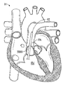
도 1a 및 도 1b는 각각 확장기 및 수축기 페이즈에서 인간 심장(H)의 절취도이다. 우심실(RV) 및 좌심실(LV)은 각각 삼첨판 판막(TV) 및 승모 판막(MV); 즉 방실 판막에 의해 우심방(RA) 및 좌심방(LA)으로부터 분리된다. 또한, 대동맥 판막(AV)은 좌심실(LV)을 상행 대동맥(확인되지 않음)으로부터 분리하고 폐 판막(PV)은 우심실을 폐동맥(PA)으로부터 분리한다. 이들 판막 각각은 각각의 오리피스에 걸쳐 내향 확장되는 가요성 첨판을 가지고 있으며, 이들 첨판은 유동 스트림에서 함께 모이거나 "유합"하여 일방향 유체 차단 표면을 형성한다. 본 출원의 도킹 스테이션 및 판막은 주로 폐 판막과 관련하여 설명된다. 따라서, 우심방(RA)과 우심실(RV)의 해부학적 구조를 보다 상세히 설명한다. 본 명세서에 설명된 디바이스는 또한 다른 영역, 예를 들어 하대정맥 및/또는 상대정맥에서 역류성 또는 기타 결함이 있는 삼첨판 판막의 치료로서, 대동맥(예를 들어, 확대 대동맥)에서 결함이 있는 대동맥 판막의 치료로서, 또는 심장 또는 혈관 구조의 다른 영역에서, 또는 그래프트 등에서 사용될 수 있다는 것을 이해하여야 한다.1A and 1B are cut-away views of a human heart (H) in diastolic and systolic phases, respectively. The right ventricle (RV) and left ventricle (LV) include the tricuspid valve (TV) and the mitral valve (MV), respectively; That is, it is separated from the right atrium (RA) and left atrium (LA) by the atrioventricular valve. In addition, the aortic valve (AV) separates the left ventricle (LV) from the ascending aorta (not identified) and the pulmonary valve (PV) separates the right ventricle from the pulmonary artery (PA). Each of these valves has a flexible leaflet that extends inwardly over a respective orifice, and these leaflets come together or "fuse" in the flow stream to form a one-way fluid barrier surface. The docking stations and valves of this application are primarily described in terms of pulmonary valves. Accordingly, the anatomical structures of the right atrium (RA) and right ventricle (RV) will be described in more detail. The devices described herein are also useful for treating defective aortic valves in the aorta (eg, dilated aorta), as treatment of regurgitating or other defective tricuspid valves in other areas, such as the inferior vena cava and/or superior vena cava. It should be understood that it can be used as a treatment, or in other areas of the heart or vascular structure, or in a graft or the like.
우심방(RA)은 상대정맥(SVC)과 하대정맥(IVC)을 통해 정맥계로부터 산소가 제거된 혈액을 받는데, 전자는 위쪽으로부터 우심방으로, 후자는 아래쪽으로부터 우심방으로 진입한다. 관상 동맥동(CS)은 심장 근육(심근)에서 산소가 제거된 혈액을 수집하여 우심방(RA)으로 전달하는 큰 혈관을 형성하기 위해 함께 결합된 정맥들의 집합이다. 도 1a에 도시된 확장기 페이즈 또는 이완기 동안, 우심방(RA)에 수집된 정맥혈은 우심실(RV)의 팽창에 의해 삼첨판 판막(TV)으로 진입한다. 도 1b에 도시된 수축기 페이즈 또는 수축기에서, 우심실(RV)은 정맥혈을 폐 판막(PV)과 폐동맥을 통해 폐로 강제 이동시키도록 수축한다. 하나의 예시적인 실시예에서, 본 출원에 의해 설명된 디바이스는 결함이 있는 폐 판막의 기능을 치환하거나 보완하기 위해 사용된다. 수축기 동안, 삼첨판 판막(TV)의 첨판은 정맥혈이 우심방(RA)으로 다시 역류하는 것을 방지하기 위해 폐쇄된다.The right atrium (RA) receives deoxygenated blood from the venous system via the superior vena cava (SVC) and the inferior vena cava (IVC), the former entering the right atrium from the superior side and the latter from the inferior vena cava. The coronary sinus (CS) is a collection of veins joined together to form a large blood vessel that collects deoxygenated blood from the heart muscle (myocardium) and delivers it to the right atrium (RA). During the diastolic phase or diastole shown in FIG. 1A , venous blood collected in the right atrium (RA) enters the tricuspid valve (TV) by expansion of the right ventricle (RV). In the systolic phase, or systole, shown in FIG. 1B, the right ventricle (RV) contracts to force venous blood through the pulmonary valve (PV) and the pulmonary artery to the lungs. In one exemplary embodiment, the device described by the present application is used to replace or supplement the function of a defective lung valve. During systole, the leaflets of the tricuspid valve (TV) close to prevent venous blood from flowing back into the right atrium (RA).
도 2a 내지 도 2e 및 도 3a 내지 도 3d를 참조하면, 도시된 비-배타적인 예는 폐동맥이 매우 다양한 상이한 형상 및 크기를 가질 수 있음을 예시한다. 예를 들어, 도 2a 내지 도 2e의 단면도 및 도 3a 내지 도 3d의 사시도에 도시된 바와 같이, 길이(L), 직경(D), 및 곡률 또는 윤곽은 상이한 환자의 폐동맥 사이에서 크게 달라질 수 있다. 또한, 직경(D)은 개별 폐동맥의 길이(L)를 따라 크게 달라질 수 있다. 이러한 차이는 특정 질환을 앓고 있는 및/또는 이전 수술에 의해 손상된 폐동맥에서 훨씬 더 중요할 수 있다. 예를 들어, 팔로의 4징후(Tetralogy of Fallot)(TOF) 또는 대동맥 전위(Transposition of the Great Arteries)(TGA)의 치료는 더 크고 더 불규칙한 형상의 폐동맥을 초래하는 경우가 많다.Referring to FIGS. 2A-2E and 3A-3D , the non-exclusive examples shown illustrate that pulmonary arteries can have a wide variety of different shapes and sizes. For example, as shown in the cross-sectional views of FIGS. 2A-2E and the perspective views of FIGS. 3A-3D , length (L), diameter (D), and curvature or contour may vary greatly between pulmonary arteries of different patients. . Also, the diameter (D) can vary greatly along the length (L) of an individual pulmonary artery. These differences may be even more significant in pulmonary arteries suffering from certain diseases and/or damaged by prior surgery. For example, treatment of the Tetralogy of Fallot (TOF) or Transposition of the Great Arteries (TGA) often results in larger and more irregularly shaped pulmonary arteries.
팔로의 4징후(TOF)는 일반적으로 함께 발생하는 4가지 관련 심장 결함의 조합을 지칭하는 심장 기형이다. 네 가지 결함은 심실 중격 결손(ventricular septal defect)(VSD), 대동맥 기승(overriding aorta)(대동맥 판막이 확장되어 정상 심장에서와 같이 좌심실 대신에 좌심실과 우심실 모두에서 발생하는 것으로 나타남), 폐 협착증(pulmonary stenosis)(우심실로부터 폐동맥으로 혈액 유동의 막힘을 생성하는 폐 판막 및 판막 아래의 유출로 또는 영역의 협착), 및 우심실 비대(우심실이 고압으로 펌핑하기 때문에 발생하는 우심실 근육벽의 두꺼워짐)이다.Four signs of Fallot (TOF) is a heart malformation that refers to a combination of four related heart defects that usually occur together. The four defects are ventricular septal defect (VSD), overriding aorta (the aortic valve is dilated and appears to develop in both the left and right ventricles instead of the left ventricle as in a normal heart), and pulmonary stenosis ( pulmonary stenosis (narrowing of the outflow tracts or areas under the valves and valves in the lungs, which creates obstruction of blood flow from the right ventricle to the pulmonary artery), and right ventricle hypertrophy (thickening of the muscular wall of the right ventricle that occurs because the right ventricle pumps at high pressure) .
대동맥 전위(TGA)는 대동맥과 폐동맥이 정상 위치에서 "전치" 되어 우심실에서 대동맥이, 좌심실에서 폐동맥이 발생하는 장애를 지칭한다.Aortic translocation (TGA) refers to a disorder in which the aorta and pulmonary artery are “displaced” from their normal positions, resulting in the aorta in the right ventricle and the pulmonary artery in the left ventricle.
일부 질환에 대한 수술 치료에는 폐동맥을 따라, 폐 가지 중 하나까지 그리고 이 가지를 따라 길이방향 절개가 수반된다. 이 절개는 폐 판막의 기능을 제거하거나 상당히 손상시킬 수 있다. 수술 후 절개를 덮기 위해 경판륜 패치가 사용된다. 경판륜 패치는 다른 수술과 관련된 폐동맥(PA)의 협착 또는 구속 상태를 감소시킨다. 그러나, 폐 판막(PV)의 손상 또는 제거는 상당한 역류를 일으킬 수 있으며, 본 발명 이전에는 종종 폐 판막을 치환하기 위해 나중에 개심 수술이 필요하였다. 경판륜 패치 기술은 크기와 형상이 매우 다양한 폐동맥을 초래할 수 있다(도 3a 내지 도 3d 참조).Surgical treatment for some diseases involves a longitudinal incision along the pulmonary artery, up to and along one of the lung branches. This incision can remove or significantly impair the function of the lung valves. An annulus patch is used to cover the incision after surgery. The transannular patch reduces stenosis or constriction of the pulmonary artery (PA) associated with other surgeries. However, damage or removal of a pulmonary valve (PV) can cause significant regurgitation, and prior to the present invention often required later open-heart surgery to replace the pulmonary valve. The transannular patch technique can result in pulmonary arteries that vary greatly in size and shape (see FIGS. 3A-3D ).
도 4a 내지 도 4f를 참조하면, 하나의 예시적인 실시예에서, 팽창 가능한 도킹 스테이션(10)은 하나 이상의 밀봉 부분(410), 판막 시트(18), 및 하나 이상의 유지 부분(414)을 포함한다. 밀봉 부분(들)(410)은 도킹 스테이션(10)과 순환계의 내부 표면(416) 사이에 밀봉부를 제공한다. 판막 시트(18)는 도킹 스테이션(10)이 순환계에 이식된 후에 도킹 스테이션(10)에 판막(29)을 이식하거나 전개하기 위한 지지 표면을 제공한다. 유지 부분(414)은 도킹 스테이션(10) 및 판막(29)을 순환계의 이식 위치 또는 전개 부위에 유지하는 것을 돕는다. 본 명세서의 다양한 실시예에서 설명된 바와 같은 팽창 가능한 도킹 스테이션(10) 및 판막(29)은 또한 공지되거나 개발될 수 있는 다양한 도킹 스테이션 및/또는 판막을 나타내며, 예를 들어 다양한 상이한 유형의 판막이 대체될 수 있고 및/또는 다양한 도킹 스테이션에서 판막(29)으로서 사용될 수 있다.Referring to FIGS. 4A-4F , in one exemplary embodiment,
도 4a 내지 도 4d는 순환계에서 도킹 스테이션(10) 및 판막(29)의 예시적인 전개를 개략적으로 예시한다. 도 4a를 참조하면, 도킹 스테이션(10)은 압축된 형태/구성이고 순환계의 전개 부위에 도입된다. 예를 들어, 도킹 스테이션(10)은, 카테터(예를 들어, 도 50a 내지 도 50d에 도시되어 있는 바와 같은 카테터(3600))에 의해 폐동맥의 전개 부위에 위치 설정될 수 있다. 도 4b를 참조하면, 도킹 스테이션(10)은 밀봉 부분(들)(410) 및 유지 부분(414)이 순환계의 일부의 내부 표면(416)과 맞물리도록 순환계 내에서 팽창된다. 도 4c를 참조하면, 도킹 스테이션(10)이 전개된 후, 판막(29)은 압축된 형태이고 도킹 스테이션(10)의 판막 시트(18) 내로 도입된다. 도 4d를 참조하면, 판막(29)이 판막 시트(18)와 맞물리도록 판막(29)이 도킹 스테이션 내에서 팽창된다. 본 명세서에 도시되어 있는 예에서, 도킹 스테이션(10)은 판막보다 길다. 그러나, 다른 실시예에서, 도킹 스테이션(10)은 판막(29)의 길이와 동일하거나 더 짧을 수 있다. 유사하게, 판막 시트(18)는 판막(29)의 길이보다 더 길거나, 더 짧거나, 동일한 길이일 수 있다.4A-4D schematically illustrate exemplary deployment of the
도 4d를 참조하면, 판막(29)은 도킹 스테이션의 시트(18)가 판막을 지지하도록 팽창되어 있다. 판막(29)은 도킹 스테이션(10)이 점유하는 순환계 부분 내의 더 넓은 공간보다는 오히려 좁은 시트(18)에 대해서만 팽창될 필요가 있다. 도킹 스테이션(10)은 판막(29)이 설계된 팽창 직경 범위 내에서 작동하게 한다.Referring to Fig. 4d, the
도 4e는 혈관 또는 심장의 해부 구조의 내부 표면과 같은 순환계의 내부 표면(416)이 그 길이를 따라 단면 크기 및/또는 형상이 달라질 수 있음을 예시한다. 예시적인 실시예에서, 도킹 스테이션(10)은 내부 표면(416)의 형상에 합치하도록 그 길이(L)를 따라 다양한 정도로 반경방향 외향으로 팽창하도록 구성된다. 하나의 예시적인 실시예에서, 도킹 스테이션(10)은, 혈관 또는 심장의 해부 구조의 형상이 도킹 스테이션의 길이(L)를 따라 상당히 달라지더라도, 밀봉 부분(들)(410) 및/또는 유지 부분(들)이 내부 표면(416)과 맞물리도록 구성된다. 도킹 스테이션은 해부 구조의 큰 변동을 수용하도록 매우 탄력적이거나 유연한 재료로 제조될 수 있다. 예를 들어, 도킹 스테이션은 매우 유연한 금속, 금속 합금, 폴리머 또는 개방 셀 발포체로 제조될 수 있다. 사용될 수 있는 금속 및 금속 합금의 예는 제한하지 않지만 니티놀, 엘길로이 및 스테인리스강을 포함하지만, 다른 금속 및 매우 탄력적이거나 유연한 비금속 재료가 사용될 수 있다. 예를 들어, 도킹 스테이션(10)은 이들 재료로, 예를 들어 니티놀과 같은 형상 기억 재료로 제조된 프레임 또는 프레임의 일부(예를 들어, 자체 팽창 프레임, 유지 부분(들), 밀봉 부분(들), 판막 시트 등)를 가질 수 있다. 이들 재료는 프레임이 작은 크기로 압축되게 하며, 이후에 압축력이 해제되는 경우, 프레임이 미리 압축된 직경으로 다시 자체 팽창하게 된다.4E illustrates that an
도킹 스테이션 또는 도킹 스테이션의 일부를 형성하기 위해 사용될 수 있는 개방 셀 발포체의 예는 폴리우레탄 발포체(예를 들어, 메릴랜드주 로크빌 소재의 Biomerix로부터 입수할 수 있는 바와 같음)와 같은 생체적합성 발포체이다. 본 명세서에 설명된 도킹 스테이션은 도킹 스테이션이 가변적인 형상을 갖는 내부 표면(416)과 맞물리게 하는 팽창 가능한 디바이스로 자체 팽창하고 및/또는 팽창 가능할 수 있다. An example of an open cell foam that can be used to form a docking station or part of a docking station is a biocompatible foam such as polyurethane foam (eg, as available from Biomerix, Rockville, MD). The docking station described herein may be self-inflating and/or inflatable with an inflatable device that allows the docking station to engage an
도 4f는 폐동맥(PA) 내에 이식된 도킹 스테이션(10) 및 판막(29)을 예시한다. 도 2a 내지 도 2e 및 도 3a 내지 도 3d와 관련하여 언급된 바와 같이, 폐동맥의 형상은 그 길이를 따라 크게 달라질 수 있다. 하나의 예시적인 실시예에서, 도킹 스테이션(10)은 도 4e와 관련하여 설명된 것과 동일한 방식으로 폐동맥(PA)의 다양한 형상에 합치하도록 구성된다.4F illustrates the
도 5a 내지 도 5f를 참조하면, 하나의 예시적인 실시예에서, 팽창 가능한 도킹 스테이션(10)은 개방 셀 생체적합성 발포체와 같은 팽창 가능한 발포체 재료로 제조된다. 발포체 재료의 외부 표면(510)은 밀봉 부분(410)의 역할을 할 수 있다. 이 예에서, 판막 시트(18)는 예시된 바와 같이 발포체 재료의 내부 표면(512) 상에 제공될 수 있거나, 내부 표면(512)이 판막 시트의 역할을 할 수 있다. 도 5a 내지 도 5f에 의해 예시된 예에서, 유지 부분(414)은 생략되지만, 유지 부분이 사용될 수 있다. 일 실시예에서, 발포체 재료는 팽창 가능한 프레임(예를 들어, 금속, 형상 기억 재료 등으로 됨)과 함께 사용될 수 있다. 발포체 재료는 프레임의 전체 길이 또는 프레임 길이의 일부만 덮거나 연장할 수 있다.Referring to FIGS. 5A-5F , in one exemplary embodiment,
도 5a 내지 도 5d는 순환계 내에서 발포체 도킹 스테이션(10) 및 판막(29)의 전개를 개략적으로 예시한다. 도 5a를 참조하면, 도킹 스테이션(10)은 압축된 형태이며 순환계의 전개 부위에 도입된다. 예를 들어, 도킹 스테이션(10)은 카테터(예를 들어, 도 50a 내지 도 50d에 도시되어 있는 카테터(3600))에 의해 폐동맥의 전개 부위에 위치 설정될 수 있다. 도 5b를 참조하면, 도킹 스테이션(10)은 밀봉 부분(410)이 순환계의 내부 표면(416)과 맞물리도록 순환계 내에서 팽창된다. 도 5c를 참조하면, 도킹 스테이션(10)이 전개된 후, 판막(29)은 압축된 형태이고 판막 시트(18) 또는 도킹 스테이션(10)의 내부 표면(512) 내로 도입된다. 도 5d를 참조하면, 판막(29)이 판막 시트(18) 또는 내부 표면(512)(예를 들어, 내부 표면(512)이 판막 시트로서 작용하는 경우)과 맞물리도록, 판막(29)이 도킹 스테이션 내에서 팽창된다.5A-5D schematically illustrate the deployment of the
도 5e는 혈관 또는 심장의 해부 구조의 내부 표면과 같은 순환계의 내부 표면(416)이 그 길이를 따라 단면이 달라질 수 있음을 예시한다. 예시적인 실시예에서, 발포체 도킹 스테이션(10)은 내부 표면(416)의 형상에 합치하도록 그 길이(L)를 따라 다양한 정도로 반경방향 외향으로 팽창하도록 구성된다.5E illustrates that an
도 5f는 폐동맥(PA) 내에 이식된 발포체 도킹 스테이션(10) 및 판막(29)을 예시한다. 도 2a 내지 도 2e 및 도 3a 내지 도 3d와 관련하여 언급된 바와 같이, 폐동맥의 형상은 그 길이를 따라 크게 달라질 수 있다. 하나의 예시적인 실시예에서, 도킹 스테이션(10)은 도 4e와 관련하여 설명된 것과 동일하거나 유사한 방식으로 폐동맥(PA)의 다양한 형상에 합치하도록 구성된다.5F illustrates the
도 6a를 참조하면, 도킹 스테이션, 예를 들어 도 4a 내지 도 4d와 관련하여 설명된 바와 같은 도킹 스테이션은 심장(H)의 폐동맥(PA) 내에 전개된다. 도 6b는 도 6a에 의해 예시된 도킹 스테이션(10) 내에서 전개된 판막(29)을 예시한다. 도 6a 및 도 6b에서, 심장은 수축기 페이즈에 있다. 도 7a는 도 6b의 폐동맥(PA)에서 도킹 스테이션(10) 및 판막(29)의 확대도이다. 심장이 수축기 페이즈에 있을 때, 판막(29)이 개방된다. 혈액은 화살표(602)로 표시된 바와 같이 우심실(RV)로부터 폐동맥(PA), 도킹 스테이션(10) 및 판막(29)을 통해 유동한다. 도 7b는 심장이 수축기 페이즈에 있을 때 개방되어 있는 판막(29)을 나타내는 혈액 충진된 공간(608)을 예시한다. 도 7b는 도면을 단순화하기 위해 도킹 스테이션(10)과 폐동맥 사이의 계면을 도시하지 않는다. 도 7b의 교차 해칭은 개방된 판막을 통한 혈액 유동을 예시한다. 예시적인 실시예에서, 밀봉 부분(들)(410)에 의해 폐동맥(PA)과 도킹 스테이션(10) 사이에 혈액이 유동하는 것이 방지되고, 도킹 스테이션(10)의 시트(18)에 판막(29)의 안착에 의해 도킹 스테이션(10)과 판막(29) 사이에 혈액이 유동하는 것이 방지된다. 이 예에서, 혈액은 심장이 수축기 페이즈에 있을 때 판막(29)을 통해서만 실질적으로 유동하거나 유동 가능하다.Referring to FIG. 6A , a docking station, for example as described with respect to FIGS. 4A-4D , is deployed in the pulmonary artery PA of the heart H. 6B illustrates
도 8은 심장이 확장기 페이즈에 있을 때 도 6b에 의해 예시된 판막(29), 도킹 스테이션(10) 및 심장(H)을 예시한다. 도 9a 및 도 9b를 참조하면, 심장이 확장기 페이즈에 있을 때, 판막(29)이 폐쇄된다. 도 9a는 도 8의 폐동맥 내에 있는 도킹 스테이션(10) 및 판막(29)의 확대도이다. 판막(29) 위의 폐동맥(PA)(즉, 폐 가지(760))의 혈액 유동은 판막(29)이 폐쇄되고 화살표(900)로 표시된 바와 같이 혈액 유동을 차단함으로써 차단된다. 도 9b의 실선 영역(912)은 심장이 확장기 페이즈에 있을 때 폐쇄되는 판막(29)을 나타낸다.8 illustrates the
하나의 예시적인 실시예에서, 도킹 스테이션(10)은 판막(29)의 반경방향 외향력이 순환계의 내부 표면(416)으로 전달되는 것을 방지하거나 실질적으로 방지하는 아이솔레이터로서 작용한다. 일 실시예에서, 도킹 스테이션(10)은 판막 시트(18)(판막 시트는 반경방향 외향으로 팽창되지 않거나 THV 또는 판막(29)의 반경방향 외향력에 의해 반경방향 외향으로 실질적으로 팽창되지 않고, 즉, 판막 시트의 직경은 증가되지 않거나 THV의 힘에 의해 4 mm 미만만큼 증가됨), 및 (판막(29)에 의해 판막 시트(18)에 인가되는 반경방향 외향력과 비교할 때) 순환계의 내부 표면(416) 상에 상대적으로 작은 반경방향 외향력(720, 722)만을 부여하는 고정/유지 부분(414) 및 밀봉 부분(410)을 포함한다.In one exemplary embodiment,
도킹 스테이션이 사용되지 않을 때, THV의 스텐트 및 프레임은 순환계의 내부 표면(416) 상에 직접 작용하는 THV의 스텐트 또는 프레임(712)의 상대적으로 높은 반경방향 외향력(710)에 의해 순환계 내의 제자리에 유지된다. 도킹 스테이션이 사용되는 경우, 도 7a에 의해 예시된 예에서와 같이, 판막(29)의 스텐트 또는 프레임(712)은 반경방향 외향으로 팽창하거나 반경방향 외향으로 팽창되어 도킹 스테이션(10)의 판막 시트(18)에 높은 힘(710)을 부여한다. 이 높은 반경방향 외향력(710)은 판막(29)을 도킹 스테이션(10)의 판막 시트(18)에 고정시킨다. 그러나, 판막 시트(18)는 힘(710)에 의해 팽창되지 않거나 실질적으로 팽창되지 않기 때문에, 힘(710)은 순환계에 도킹 스테이션을 고정하는 데 사용되기 보다는 순환계로부터 격리된다.When the docking station is not in use, the stent and frame of the THV are held in place within the circulatory system by the relatively high radial
예시적인 실시예에서, 내부 표면(416)에 대한 밀봉 부분(410)의 반경방향 외향력(722)은 판막 시트(18)에 판막(29)에 의해 인가되는 반경방향 외향력(710)보다 실질적으로 더 작다. 예를 들어, 반경방향 외향 밀봉력(722)은 판막에 의해 인가되는 반경방향 외향력(710)의 1/2 미만, 판막에 의해 인가되는 반경방향 외향력(710)의 1/3 미만, 판막에 의해 인가되는 반경방향 외향력(710)의 1/4 미만, 판막에 의해 인가되는 반경방향 외향력(710)의 1/8 미만, 또는 심지어는 1/10 미만일 수 있다. 하나의 예시적인 실시예에서, 밀봉 부분(410)의 반경방향 외향력(722)은 내부 표면(416)과 밀봉 부분(410) 사이의 밀봉부를 제공하도록 선택되지만, 순환계에서 판막(29)과 도킹 스테이션(10)의 위치를 유지하기에 그 자체로는 충분하지 않다.In an exemplary embodiment, the radial
예시적인 실시예에서, 내부 표면(416)에 대한 고정/유지 부분(414)의 반경방향 외향력(720)은 판막(29)에 의해 판막 시트(18)에 인가되는 반경방향 외향력(710)보다 실질적으로 더 작다. 예를 들어, 반경방향 외향 밀봉력(720)은 판막에 의해 인가되는 반경방향 외향력(710)의 1/2 미만, 판막에 의해 인가되는 반경방향 외향력(710)의 1/3 미만, 판막에 의해 인가되는 반경방향 외향력(710)의 1/4 미만, 판막에 의해 인가되는 반경방향 외향력(710)의 1/8 미만, 또는 심지어는 1/10 미만일 수 있다.In an exemplary embodiment, the radial
하나의 예시적인 실시예에서, 유지 부분(414)의 반경방향 외향력(720)은 순환계에서 판막(29) 및 도킹 스테이션(10)의 위치를 유지하기에 그 자체로 충분하지 않다. 오히려, 혈액(608)의 압력은 내부 표면(416)에 대한 유지 부분(414)의 보유를 개선시키는 데 사용된다. 다시 도 6a를 참조하면, 심장이 수축기 페이즈에 있을 때, 판막(29)이 개방되고 혈액이 화살표(602)로 표시된 바와 같이 판막을 통해 유동한다. 판막(29)이 개방되어 있고 혈액이 판막(29)을 통해 유동하기 때문에, 혈액에 의해 도킹 스테이션(10) 및 판막(29)에 인가되는 압력(P)은 도 7a에서 작은 P 및 화살표로 표시된 바와 같이 낮다. 작지만 압력(P)은 일반적으로 화살표(F)로 표시된 방향으로 표면(416)에 대해 도킹 스테이션 및 그 상부 유지 부분(414)을 강제한다. 유지 부분(F)에 의해 표면(416)에 인가되는 이러한 혈액 유동 보조 힘(F)은 도킹 스테이션(10) 및 판막(29)이 심장(H)의 수축기 페이즈에서 혈액 유동의 방향(602)으로 이동하는 것을 방지한다.In one exemplary embodiment, the radial
도 9a를 참조하면, 심장이 확장기 페이즈에 있을 때, 판막(29)이 폐쇄되고 혈액 유동이 화살표(900)로 표시된 바와 같이 차단된다. 판막(29)이 폐쇄되어 있고 판막(29)과 도킹 스테이션(10)이 혈액의 유동을 차단하기 때문에, 혈액에 의해 도킹 스테이션(10)과 판막(29)에 인가되는 압력(P)은 도 9a에서 큰 화살표(P)로 표시된 바와 같이 높다. 이 큰 압력(P)은 일반적으로 큰 화살표(F)로 표시된 방향으로 표면(416)에 대해 하부 유지 부분(414)을 강제한다. 유지 부분(F)에 의해 표면(416)에 인가되는 이러한 혈액 유동 보조 힘(F)은 도킹 스테이션(10) 및 판막(29)이 화살표(900)로 표시된 방향으로 이동하는 것을 방지한다.Referring to FIG. 9A , when the heart is in diastolic phase,
상부 및 하부 유지 부분(414)에 의해 인가되는 힘은 혈액에 의해 판막(29) 및 도킹 스테이션(10)에 인가되는 압력의 양에 의해 결정되기 때문에, 표면(416)에 인가되는 힘은 자동으로 비율화된다. 즉, 심장이 확장기 페이즈에 있을 때 하부 유지 부분이 표면(416)에 대해 가압되는 것보다 심장이 수축기 페이즈에 있을 때 상부 유지 부분이 표면(416)에 대해 덜 세게 가압된다. 이는 수축기 페이즈에서 개방된 판막(29) 및 도킹 스테이션(10)에 대한 압력이 확장기 페이즈에서 폐쇄된 판막 및 도킹 스테이션에 대한 압력보다 더 작기 때문이다.Since the force applied by the upper and
판막 시트(18) 및 밀봉 부분(410)은 매우 다양한 상이한 형태를 취할 수 있다. 예를 들어, 판막 시트(18)는 반경방향 외향으로 팽창되지 않거나 THV의 반경방향 외향력에 의해 반경방향 외향으로 실질적으로 팽창되지 않는 임의의 구조일 수 있다(즉, 전개된 위치/구성에서 판막 시트의 직경은 팽창되지 않을 수 있거나, 4 mm 미만으로 팽창될 수 있고, 예를 들어 판막이 판막 시트에서 전개될 때 직경이 1-4 mm만 더 크게 팽창될 수 있음). 예를 들어, 판막 시트(18)는 팽창을 저지하거나 제한하는 봉합사 또는 금속 링을 포함할 수 있다. 그러나, 일 실시예에서, 판막 시트(18)(또는 본 명세서에 설명된 임의의 판막 시트)는 더 큰 범위에 걸쳐 팽창 가능할 수 있으며, 예를 들어, 판막이 판막 시트에서 전개될 때 직경은 5 mm 내지 30 mm 더 크게 팽창될 수 있다. 일 실시예에서, 직경은 직경이 5 mm 또는 6 mm로부터 직경이 20 mm-29 mm, 24 mm, 26 mm, 29 mm 등으로 팽창되거나, 그 범위 내에서 상이한 직경으로 팽창될 수 있다. 더 팽창 가능하더라도, 판막 시트는 여전히 팽창이 제한될 수 있으며, 예를 들어, 판막 시트에 배치될 판막의 팽창된 직경을 초과하는 판막 시트의 팽창을 방지하거나 그 사이에 생성된 힘을 통해 판막 시트에 판막을 견고하게 유지할 직경을 초과하는 팽창을 방지하기 위해 제한될 수 있다. 판막 시트(18)는 도킹 스테이션(10)의 본체의 일부이거나 그 본체의 일부를 형성할 수 있거나, 판막 시트(18)는 도킹 스테이션의 본체에 부착되는 별개의 구성요소일 수 있다. 판막 시트(18)는 판막보다 더 길거나, 더 짧거나, 동일한 길이일 수 있다. 판막 시트(18)가 봉합사 또는 금속 링에 의해 형성될 때 판막 시트(18)는 판막(29)보다 상당히 짧을 수 있다. 봉합사 또는 금속 링에 의해 형성된 판막 시트(18)는 판막(29)과 도킹 스테이션 사이에 좁은 원주방향 밀봉 라인을 형성할 수 있다.The
다양한 실시예의 밀봉 부분(들)(410)은 매우 다양한 상이한 형태를 취할 수 있다. 예를 들어, 밀봉 부분(들)(410)은 도킹 스테이션(10)과 순환계의 표면(416) 사이에 밀봉부(들)를 제공하는 임의의 구조일 수 있다. 예를 들어, 밀봉 부분(들)(410)은 직물, 발포체, 생체적합성 조직, 팽창 가능한 금속 프레임, 이들의 조합 등을 포함할 수 있다. 밀봉 부분(들)(410)은 도킹 스테이션(10)의 본체의 일부이거나 그 본체의 일부를 형성할 수 있고, 및/또는 밀봉 부분(들)(410)은 도킹 스테이션의 본체에 부착되는 별개의 구성요소일 수 있다. 도킹 스테이션(10)은 단일 밀봉 부분(410) 또는 2개, 또는 2개 초과의 밀봉 부분을 포함할 수 있다.The sealing portion(s) 410 of various embodiments may take a wide variety of different forms. For example, seal(s) 410 may be any structure that provides seal(s) between
앞서 설명한 바와 같이, 하나의 예시적인 실시예에서, 밀봉 부분(들)(410)은 표면(416)에 낮은 반경방향 외향력을 인가하도록 구성된다. 낮은 반경방향 외향력은 매우 다양한 상이한 방식으로 제공될 수 있다. 예를 들어, 밀봉 부분은 매우 압축성이거나 유연한 재료로 제조될 수 있다. 도 7c를 참조하면, 하나의 예시적인 실시예에서, 도킹 스테이션(10) 본체는 탄성 또는 초탄성 금속으로 제조된다. 이러한 금속 중 하나는 니티놀이다. 도킹 스테이션(10)의 본체가 금속 스트러트의 격자로 제조될 때, 본체는 스프링의 특성을 가질 수 있다. 도 7c를 참조하면, 스프링과 같이, 도킹 스테이션의 본체가 구속되지 않고 그 최대 직경으로 이완되는 것이 허용될 때, 도킹 스테이션의 본체는 반경방향 외향력을 거의 또는 전혀 인가하지 않는다. 도킹 스테이션(10)의 본체가 스프링과 같이 압축됨에 따라, 도킹 스테이션에 의해 인가되는 반경방향 외향력이 증가한다. 도 7c에 의해 예시된 바와 같이, 하나의 예시적인 실시예에서, 도킹 스테이션의 팽창된 직경에 대한 도킹 스테이션 본체의 반경방향 외향력의 관계는 비선형이지만, 하나의 예시적인 실시예에서, 그 관계는 또한 선형일 수 있다. 도 7c에 의해 예시된 예에서, 곡선(750)은 도킹 스테이션(10)에 의해 인가되는 반경방향 외향력과 도킹 스테이션의 압축된 직경 사이의 관계를 예시한다. 영역(752)에서, 곡선(750)은 낮은 기울기를 갖는다. 이 영역(752)에서, 반경방향 외향력은 낮고 소량만 변화한다. 하나의 예시적인 실시예에서, 영역(752)은 25 mm 내지 40 mm, 예컨대 27 mm 내지 38 mm의 직경에 대응한다. 반경방향 외향력은 영역(752)에서 작지만 0은 아니다. 영역(754)에서, 곡선(750)은 더 높은 기울기를 갖는다. 이 영역(754)에서, 반경방향 외향력은 도킹 스테이션이 압축됨에 따라 상당히 증가한다. 하나의 예시적인 실시예에서, 스텐트의 본체는 낮은 기울기 영역(752)에 있도록 구성된다. 이는 밀봉 부분(410)이 넓은 범위의 직경에 걸쳐 순환계의 내부 표면(416)에 작은 반경방향 외향력만을 인가하게 한다.As previously discussed, in one exemplary embodiment, sealing portion(s) 410 are configured to apply a low radial outward force to surface 416 . Low radial outward force can be provided in a wide variety of different ways. For example, the sealing portion may be made of a material that is highly compressible or flexible. Referring to FIG. 7C , in one exemplary embodiment, the
유지 부분(414)은 매우 다양한 상이한 형태를 취할 수 있다. 예를 들어, 유지 부분(들)(414)은 순환계에서 도킹 스테이션(10)의 위치를 설정하는 임의의 구조일 수 있다. 예를 들어, 유지 부분(들)(414)은 도킹 스테이션(10)의 위치를 설정하기 위해 내부 표면(416)에 대해 또는 내부 표면 내로 가압되거나 순환계의 해부학적 구조 둘레에서 연장될 수 있다. 유지 부분(들)(414)은 도킹 스테이션(10)의 본체의 일부이거나 그 본체의 일부를 형성할 수 있거나, 또는 유지 부분(들)(414)은 도킹 스테이션의 본체에 부착되는 별개의 구성요소일 수 있다. 도킹 스테이션(10)은 단일 유지 부분(414) 또는 2개, 또는 2개 초과의 유지 부분을 포함할 수 있다.The retaining
도 10a 내지 도 10c는 도킹 스테이션(10)이 하나 이상의 상이한 유형의 판막 시트(18) 및 밀봉 부분(410)의 임의의 조합을 가질 수 있음을 예시한다. 도 10a에 의해 예시된 예에서, 판막 시트(18)는 도킹 스테이션(10)의 본체에 부착되는 별개의 구성요소이고 밀봉 부분은 도킹 스테이션의 본체와 일체로 형성된다. 도 10b에 의해 예시된 예에서, 판막 시트(18)는 도킹 스테이션(10)의 본체에 부착되는 별개의 구성요소이고 밀봉 부분(410)은 도킹 스테이션의 본체에 부착되는 별개의 구성요소이다. 도 10c에 의해 예시된 예에서, 판막 시트(18)는 도킹 스테이션(10)의 본체와 일체로 형성되고 밀봉 부분은 도킹 스테이션의 본체와 일체로 형성된다. 도 10d에 의해 예시된 예에서, 판막 시트(18)는 도킹 스테이션(10)의 본체와 일체로 형성되고 밀봉 부분은 도킹 스테이션(10)의 본체에 부착되는 별개의 구성요소이다.10A-10C illustrate that
전술한 바와 같이, 폐동맥(PA)의 길이 및 순환계의 기타 해부학적 구조는 환자마다 크게 달라질 수 있다. 도 11a 내지 도 11d를 참조하면, 하나의 예시적인 실시예에서, 도킹 스테이션(10)의 길이는 화살표(1100)로 표시된 바와 같이 조절 가능하다. 이러한 조절성(1100)은 스텐트가 압축된 상태에서 팽창된 상태로 팽창할 때 발생하는 고유의 길이 변화가 아니라 조절되는 도킹 스테이션의 이식된/팽창된 길이의 능력을 지칭한다. 길이는 매우 다양한 상이한 방법으로 조절될 수 있다. 도 11a 내지 도 11d에 의해 예시된 예에서, 도킹 스테이션(10)은 제1 절반부(1102) 및 제2 절반부(1104)를 포함한다. 2-부품 도킹 스테이션과 관련하여 본 명세서에서 사용된 "절반부"라는 단어의 사용은 "부분"과 동의어이며 제1 및 제2 절반부 또는 제1 및 제2 부분이 크기가 동일할 필요가 없고, 즉, 제1 절반부는 제2 절반부보다 크거나/길수 있으며 그 반대의 경우도 마찬가지이다. 일 실시예에서, 제2 절반부(1104)는 제1 절반부(1102)에 삽입되거나 "텔레스코핑"될 수 있다. 삽입 또는 "텔레스코핑"의 양은 도킹 스테이션(10)의 길이를 설정한다. 본 특허 출원에 도시되고 설명된 도킹 스테이션(10) 중 임의의 것은 함께 텔레스코핑되거나 달리 서로에 대해 조절 가능한 2개의 부품으로부터 도킹 스테이션을 제조함으로써 길이가 조절 가능할 수 있다. 일 실시예에서, 단일 부품 도킹 스테이션의 길이는 절첩 가능하고 팽창 가능할 수 있다. 일 실시예에서, 도킹 스테이션은 길이를 조절하기 위해 형상을 변경할 수 있는 재료로 형성될 수 있다. 일 실시예에서, 2개보다 많은 부분(예를 들어, 3, 4 또는 그 이상의 부분)이 유사한 방식으로 조합될 수 있고 제1 절반부(1102) 및 제2 절반부(1104)와 유사한 특징을 하나 이상 포함할 수 있다.As noted above, the length of the pulmonary artery (PA) and other anatomy of the circulatory system can vary greatly from patient to patient. Referring to FIGS. 11A-11D , in one exemplary embodiment, the length of
하나의 예시적인 실시예에서, 도킹 스테이션(10)의 길이는 먼저 도킹 스테이션(10)의 제1 절반부(1102)를 폐동맥 내에서 전개함으로써 폐동맥(PA) 내에서 조절될 수 있다. 예를 들어, 제1 절반부(1102)는, 예를 들어 제1 절반부의 원위 단부(1106)가 폐동맥의 가지와 정렬되거나 가지를 약간 지나서 연장되도록 원하는 대로 위치 설정되고 팽창될 수 있다. 제1 절반부(1102)가 폐동맥 내에서 팽창된 후, 압축된 제2 절반부(1104)는 제1 절반부(1102)의 근위 단부(1108)에 배치된 원위 단부(1110)와 함께 위치 설정될 수 있다. 일 실시예에서, 제2 절반부(1104)의 위치는 밀봉 부분(410) 및 유지 부분(414)이 폐동맥과 접촉하고 폐동맥에서 도킹 스테이션(10)의 위치를 설정하도록 선택된다. 일단 적절하게 위치 설정되면, 제2 절반부(1104)가 팽창된다. 일 실시예에서, 제2 절반부(1104)의 원위 단부(1110)는 제1 절반부의 근위 단부(1108)와 마찰식으로 맞물려 2개의 절반부(1102, 1104)를 함께 고정한다. 일 실시예에서, 잠금 장치(들), 로킹 메커니즘, 봉합사(들), 인터레이싱, 링크(들) 및/또는 다른 부착 디바이스/메커니즘을 사용하여 절반부들/부분들을 함께 고정하는 것을 도울 수 있다.In one exemplary embodiment, the length of the
도 11a 내지 도 11d에 의해 예시된 예에서, 시트(18) 및 밀봉 부분(410)은 도킹 스테이션(10)의 제2 절반부(1104)에 포함된다. 그러나, 다른 실시예에서, 시트(18) 및/또는 밀봉 부분(410)은 제1 절반부(1102)에 포함될 수 있다. 도 11a 내지 도 11c는 도킹 스테이션(10)의 절반부(1102, 1104)가 상이한 유형의 판막 시트(18) 및 밀봉 부분(410)의 임의의 조합을 가질 수 있음을 예시한다. 도 11a에 의해 예시된 예에서, 판막 시트(18)는 도킹 스테이션 절반부(1104)의 본체에 부착되는 별개의 구성요소이고 밀봉 부분은 도킹 스테이션 절반부(1104)의 본체와 일체로 형성된다. 도 11b에 의해 예시된 예에서, 판막 시트(18)는 도킹 스테이션 절반부(1104)의 본체에 부착되는 별개의 구성요소이고 밀봉 부분(410)은 도킹 스테이션 절반부(1104)의 본체에 부착되는 별개의 구성요소이다. 도 11c에 의해 예시된 예에서, 판막 시트(18)는 도킹 스테이션 절반부(1104)의 본체와 일체로 형성되고 밀봉 부분은 도킹 스테이션 절반부(1104)의 본체와 일체로 형성된다. 도 11d에 의해 예시된 예에서, 판막 시트(18)는 도킹 스테이션 절반부(1104)의 본체와 일체로 형성되고 밀봉 부분(410)은 도킹 스테이션 절반부(1104)의 본체에 부착되는 별개의 구성요소이다.In the example illustrated by FIGS. 11A-11D , the
도 12a 내지 도 12d는 2개의 밀봉 부분(410)을 갖는 도킹 스테이션(10)의 예시적인 실시예를 예시한다. 도킹 스테이션(10)은 하나 이상의 상이한 유형의 판막 시트(18) 및 밀봉 부분(410)의 임의의 조합을 가질 수 있다. 도 12a에 의해 예시된 예에서, 판막 시트(18)는 도킹 스테이션(10)의 본체에 부착되는 별개의 구성요소이고 밀봉 부분(410)은 도킹 스테이션의 본체와 일체로 형성된다. 도 12b에 의해 예시된 예에서, 판막 시트(18)는 도킹 스테이션(10)의 본체에 부착되는 별개의 구성요소이고 밀봉 부분(410)은 도킹 스테이션의 본체에 부착되는 별개의 구성요소이다. 도 12c에 의해 예시된 예에서, 판막 시트(18)는 도킹 스테이션(10)의 본체와 일체로 형성되고 밀봉 부분은 도킹 스테이션의 본체와 일체로 형성된다. 도 12d에 의해 예시된 예에서, 판막 시트(18)는 도킹 스테이션(10)의 본체와 일체로 형성되고 밀봉 부분은 도킹 스테이션(10)의 본체에 부착되는 별개의 구성요소이다.12A-12D illustrate an exemplary embodiment of a
도 13a 내지 도 13d는 도 12a 내지 도 12d에 의해 예시된 도킹 스테이션이 2-피스 신축식 도킹 스테이션일 수 있음을 예시한다. 도킹 스테이션(10)의 피스(1102, 1104)는 하나 이상의 상이한 유형의 판막 시트(18) 및 2개의 피스 중 하나 또는 양자 모두에 있는 밀봉 부분(410)의 임의의 조합을 가질 수 있다. 도 13a에 의해 예시된 예에서, 제1 절반부(1102)는 일체형 밀봉 부분(410)을 포함한다. 제2 절반부(1104)는 도킹 스테이션(10)의 본체에 부착되는 별개의 구성요소인 판막 시트(18)를 포함하고 밀봉 부분(410)은 도킹 스테이션의 본체와 일체로 형성된다. 도 13b에 의해 예시된 예에서, 제1 절반부(1102)는 제1 절반부(102)의 본체와 별개인 밀봉 부분(410)을 포함한다. 판막 시트(18)는 도킹 스테이션(10)의 본체에 부착되는 별개의 구성요소이고 밀봉 부분(410)은 도킹 스테이션의 본체에 부착되는 별개의 구성요소이다. 도 13c에 의해 예시된 예에서, 제1 절반부(1102)는 일체형 밀봉 부분(410)을 포함한다. 판막 시트(18)는 도킹 스테이션(10)의 제2 절반부(1104)의 본체와 일체로 형성되고 밀봉 부분(410)은 제2 절반부(1104)의 본체와 일체로 형성된다. 도 13d에 의해 예시된 예에서, 제1 절반부(1102)는 제1 절반부(102)의 본체와 별개인 밀봉 부분(410)을 포함한다. 판막 시트(18)는 도킹 스테이션(10)의 제2 절반부(1104)의 본체와 일체로 형성되고 밀봉 부분(410)은 제2 절반부(1104)의 본체에 부착되는 별개의 구성요소이다.13A-13D illustrate that the docking station illustrated by FIGS. 12A-12D may be a two-piece telescoping docking station. The
도 14a 내지 도 14g를 참조하면, 하나의 예시적인 실시예에서, 도킹 스테이션(10)은 화살표(1402)로 표시된 바와 같이 혈액이 통과할 수 있는 투과성 부분(1400) 및 혈액이 통과할 수 없는 불투과성 부분(1404)을 포함할 수 있다. 하나의 예시적인 실시예에서, 불투과성 부분(1404)은 혈액이 판막(29) 둘레에서 유동하는 것을 방지하기 위해 적어도 밀봉 부분(410)으로부터 판막 시트(18)까지 연장된다. 하나의 예시적인 실시예에서, 투과성 부분(1400)은 혈액이 투과성 부분을 통해 자유롭게 유동하게 하여, 순환계의 내부 표면(416)에 대해 밀봉되지 않거나 판막(29)에 대해 밀봉되지 않는 도킹 스테이션의 부분이 혈액의 유동을 차단하지 않도록 한다. 예를 들어, 도킹 스테이션(10)은 폐동맥의 가지 내로 연장될 수 있고, 도킹 스테이션(10)의 폐동맥으로 연장되는 부분(1400)은 혈액이 도킹 스테이션(10)을 통해 자유롭게 유동할 수 있게 한다. 하나의 예시적인 실시예에서, 투과성 부분(1400)은 혈액이 투과성 부분을 통해 자유롭게 유동하게 하여, 도킹 스테이션과 순환계 사이의 영역(1420)이 심장 박동에 따라 혈액으로 플러싱되어, 영역(1420)에서 울혈(blood stasis)을 방지한다.Referring to FIGS. 14A-14G , in one exemplary embodiment,
불투과성 부분(1404)은 매우 다양한 상이한 형태를 취할 수 있다. 불투과성 부분(1404)은 혈액이 불투과성 부분(1404)을 통해 유동하는 것을 방지하는 임의의 구조 또는 재료일 수 있다. 예를 들어, 도킹 스테이션(10)의 본체는 니티놀 와이어 또는 격자와 같은 와이어 또는 격자로 형성될 수 있고, 본체의 셀은 불투과성 재료로 덮여 있다(도 18 참조). 매우 다양한 상이한 재료가 불투과성 재료로 사용될 수 있다. 예를 들어, 불투과성 재료는 PET 천과 같은 혈액 불투과성 천 또는 혈액에 대해 불투과성인 코팅으로 처리된 직물, 폴리에스테르, 또는 심막과 같은 처리된 생물학적 재료와 같은 생체적합성 커버링 재료일 수 있다.The
도 14a 내지 도 14g는 매우 다양한 도킹 스테이션 구성에 투과성 부분(1400)이 제공될 수 있음을 예시한다. 밀봉 부분(410)은 도 14b, 14d 및 14f에 의해 예시된 바와 같이 도킹 스테이션의 본체와 일체로 형성되거나 도 14c, 14e 및 14g에 의해 예시된 바와 같이 별개일 수 있다. 도 14f 및 도 14g에서, 도킹 스테이션(10)은 부분(1410)을 포함한다. 이들 부분(1410)은 밀봉 부분(410)과 유사하지만, 부분(1410)이 투과성 부분(1400)의 일부이기 때문에 순환계의 내부 표면(416)과 밀봉부가 형성되지 않는다. 판막 시트(18)는 도 14a 내지 도 14c에 의해 예시된 바와 같이 도킹 스테이션의 본체로부터 별개로 형성되거나 도 14d 내지 도 14g에 의해 예시된 바와 같이 도킹 스테이션(10)의 본체와 일체로 형성될 수 있다.14A-14G illustrate that the
도 15a, 15b, 16, 17a 및 17b는 도킹 스테이션(10)의 본체 또는 프레임(1500)의 예시적인 실시예를 예시한다. 프레임(1500) 또는 본체는 매우 다양한 상이한 형태를 취할 수 있고 도 15a, 15b, 16, 17a 및 17b는 많은 가능한 구성 중 단지 하나를 예시한다. 도 15a, 15b, 16, 17a, 17b 및 18에 의해 예시된 예에서, 도킹 스테이션(10)은 비교적 넓은 근위 유입 단부(12) 및 원위 유출 단부(14), 및 단부(12, 14) 사이에 시트(18)를 형성하는 비교적 좁은 부분(16)을 갖는다. 도 15a, 15b, 17a 및 17b에 의해 예시된 예에서, 도킹 스테이션(10)의 프레임(1500)은 바람직하게는 셀(1504)을 형성하는 복수의 금속 스트러트(1502)로 구성된 넓은 스텐트이다. 도 15a, 15b, 17a 및 17b의 예에서, 프레임(1500)은 근위 단부(12)와 원위 단부(14) 사이에서 불투과성 재료에 의해 덮일 때 판막 시트(18)를 형성하는 좁은 부분(16)을 갖는 대체로 모래시계 형상을 갖는다. 아래에 설명되는 바와 같이, 판막(29)은 판막 시트(18)를 형성하는 좁은 부분(16)에서 팽창한다.15A , 15B , 16 , 17A and 17B illustrate an example embodiment of a body or
도 15a, 15b, 17a 및 17b는 구속되지 않고 팽창된 상태의 프레임(1500)을 예시한다. 이 예시적인 실시예에서, 유지 부분(414)은 근위 단부(12) 및 원위 단부(14)에서 금속 스트러트(1502)의 단부 또는 정점(1510)을 포함한다. 밀봉 부분(410)은 유지 부분(414)과 허리(16) 사이에 있다. 구속되지 않은 상태에서, 유지 부분(414)은 대체로 반경방향 외향으로 연장되고 밀봉 부분(410)의 반경방향 외향에 있다. 도 16은 카테터에 의한 전달 및 팽창을 위해 압축된 상태에 있는 프레임을 예시한다. 도킹 스테이션은 해부 구조의 큰 변동을 수용하도록 매우 탄력적이거나 유연한 재료로 제조될 수 있다. 예를 들어, 도킹 스테이션은 매우 유연한 금속, 금속 합금, 폴리머 또는 개방 셀 발포체로 제조될 수 있다. 매우 탄력적인 금속의 예로는 니티놀을 들 수 있지만, 다른 금속 및 고도로 탄력적인 또는 유연한 비금속 재료가 사용될 수 있다. 도킹 스테이션(10)은 자체 팽창, 수동 팽창 가능(예를 들어, 벌룬을 통해 팽창 가능), 또는 기계적 팽창 가능할 수 있다. 자체 팽창 도킹 스테이션(10)은, 예를 들어 니티놀과 같은 형상 기억 재료로 제조될 수 있다.15A, 15B, 17A and 17B illustrate
도 18은 도킹 스테이션(10)을 형성하기 위해 불투과성 재료(21)가 프레임(1500)에 부착되어 있는 프레임(1500)을 예시한다. 도 18을 참조하면, 하나의 예시적인 실시예에서, 밴드(20)는 허리 또는 좁은 부분(16) 둘레에서 연장되거나, 또는 허리에 일체로 되어 팽창 불가능하거나 실질적으로 팽창 불가능한 판막 시트(18)를 형성한다. 밴드(20)는 허리를 강성화하고, 일단 도킹 스테이션이 전개되고 팽창되면, 그 전개된 구성에서 허리/판막 시트가 상대적으로 팽창 불가능하게 만든다. 도 19에 의해 예시된 예에서, 판막(29)은 그 절첩 가능한 프레임을 도킹 스테이션(10)의 판막 시트(18)를 형성하는 좁은 부분(16)으로 팽창함으로써 고정된다. 앞서 설명한 바와 같이, 팽창 불가능하거나 실질적으로 팽창 불가능한 판막 시트(18)는 판막(29)의 반경방향 외향력이 순환계의 내부 표면(416)으로 전달되는 것을 방지한다. 그러나, 다른 예시적인 실시예에서, 전개된 도킹 스테이션의 허리/판막 시트는 판막이 그에 대해 전개될 때 임의로 탄성 방식으로 약간 팽창할 수 있다. 허리/판막 시트(18)의 임의적인 탄성 팽창은 판막(29)에 압력을 가하여 도킹 스테이션 내에서 판막(29)을 제자리에 유지하는 데 도움이 될 수 있다.18 illustrates
밴드는 매우 다양한 상이한 형태를 취할 수 있으며 매우 다양한 상이한 재료로 제조될 수 있다. 밴드(20)는 PET, 하나 이상의 봉합사, 직물, 금속, 폴리머, 생체적합성 테이프, 또는 판막 시트(18)의 형상을 유지하고 판막(29)을 제자리에 유지하기에 충분한 본 기술 분야에 알려진 다른 비교적 팽창 불가능한 재료로 제조될 수 있다. 밴드는 스텐트의 외부 둘레로 연장될 수 있거나, 직물 또는 다른 재료가 스텐트의 셀 내부로 또는 스텐트의 셀을 통해 인터위빙되는 경우와 같이 스텐트의 일체형 부분일 수 있다. 밴드(20)는 도 18의 봉합사 밴드와 같이 좁거나 더 넓을 수 있다. 밴드는 다양한 폭, 길이 및 두께가 될 수 있다. 하나의 비제한적인 예에서, 판막 시트(18)는 폭이 27-28 mm이지만, 판막 시트의 직경은 판막 시트(18) 내에 고정될 특정 판막(29)의 작동 범위 내에 있어야 하고, 전술한 예와 상이할 수 있다. 판막(29)은, 도킹 스테이션 내에 도킹될 때, 임의로 판막 시트의 양 측면 둘레에서 약간 팽창될 수 있다. 때때로 "개 뼈"라고 지칭되는 이 양태(예를 들어, 판막 시트 또는 밴드 둘레에 형성되는 형상 때문에)는 또한 판막을 제자리에 유지하는 데 도움이 될 수 있다.The band can take a wide variety of different shapes and can be made of a wide variety of different materials.
도 20 및 도 21은 폐동맥과 같은 순환계에 이식된 도 18의 도킹 스테이션(10)을 예시한다. 밀봉 부분(410)은 도킹 스테이션(10)과 순환계의 내부 표면(416) 사이에 밀봉부를 제공한다. 도 20 및 도 21의 예에서, 밀봉 부분(410)은 프레임(1500) 또는 그 일부 위에 불투과성 재료(21)(도 21 참조)를 제공함으로써 형성되며, 특히 밀봉 부분(410)은 프레임(1500)의 하부, 둥근, 반경방향 외향 연장 부분(2000)을 포함할 수 있다. 예시적인 실시예에서, 불투과성 재료(21)는 프레임(1500)의 적어도 부분(2000)으로부터 판막 시트(18)까지 연장된다. 이는 도킹 스테이션을 밀봉 부분(410)으로부터 판막 시트(18)까지 불투과성으로 만든다. 이와 같이, 유출 단부(14)를 향해 유입 단부(12)의 방향으로 유동하는 모든 혈액은 판막 시트(18)(및 판막 시트에 일단 설치되거나 전개되면 판막(29))로 지향된다.20 and 21 illustrate the
도킹 스테이션(10)의 바람직한 실시예에서, 유입 부분은 혈액에 대해 불투과성인 벽을 갖지만, 유출 부분 벽은 비교적 개방되어 있다. 하나의 접근법에서, 유입 단부 부분(12), 중간 섹션(16), 및 유출 단부 부분(14)의 일부는 스텐트 상에 재봉될 수 있거나 당업계에 알려진 방법에 의해 달리 부착될 수 있는 혈액 불투과성 직물(21)로 덮인다. 스텐트의 유입 부분의 불투과성은 혈액이 도킹 스테이션(10)으로 유입되고 궁극적으로 도킹 스테이션(10) 내에서 팽창되고 고정될 판막을 통해 유동하는 데 도움이 된다.In a preferred embodiment of the
다른 관점에서, 도킹 스테이션의 이 실시예는 혈액 유동을 위한 도관을 생성하기 위해 근위 유입 섹션(2000)에서 밀봉하도록 설계된다. 그러나, 원위 유출 섹션은 일반적으로 개방된 상태로 남겨 두어, 도킹 스테이션(10)이 혈액 유동을 제한하지 않고 폐동맥에서 더 높게 위치될 수 있게 한다. 예를 들어, 투과성 부분(1400)은 폐동맥의 가지로 연장될 수 있고 가지를 지나는 혈액의 유동을 방해하지 않거나 현저히 방해하지 않을 수 있다. 일 실시예에서, 예를 들어 PET 천과 같은 혈액 불투과성 천 또는 다른 재료가 근위 유입 섹션을 덮지만, 커버링은 원위 유출 섹션(14)의 임의의 일부를 덮지 않거나 적어도 그 일부를 덮지 않는다. 하나의 비제한적인 예로서, 도킹 스테이션(10)이 큰 혈관인 폐동맥에 배치될 때, 동맥을 통해 유동하는 상당한 양의 혈액이 불투과성 재료(21)에 의해 판막(29)으로 유입된다. 천(21)은 혈액이 통과할 수 없도록 유체 불투과성이다. 다시 말해서, 예를 들어 혈액에 대해 불투과성인 코팅으로 처리된 발포체 또는 직물, 폴리에스테르, 또는 심막과 같은 처리된 생물학적 재료과 같은 다양한 다른 생체적합성 커버링 재료가 사용될 수 있다.From another point of view, this embodiment of the docking station is designed to seal at the
도 21에 의해 예시된 예에서, 도킹 스테이션 프레임(1500)의 더 많은 부분에 불투과성 재료(21)가 제공되어 비교적 큰 불투과성 부분(1404)을 형성한다. 도 21에 의해 예시된 예에서, 불투과성 부분(1404)은 유입 단부(12)로부터 연장되고 유출 단부 이전에 한 행의 셀(1504)을 정지시킨다. 이와 같이, 셀(1504)의 가장 원위 행은 투과성 부분(1400)을 형성한다. 그러나, 더 많은 행의 셀(1504)이 불투과성 재료에 의해 덮이지 않아 더 큰 투과성 부분을 형성할 수 있다. 투과성 부분(1400)은 화살표(2132)로 표시된 바와 같이 혈액이 영역(2130) 안팎으로 유동할 수 있게 한다. 즉, 혈액은 하나의 예시적인 실시예에서 영역(2100) 안팎으로 유동할 수 있다.In the example illustrated by FIG. 21 , a larger portion of the
판막 시트(18)는 도킹 스테이션(10)에 판막(29)을 이식하거나 전개하기 위한 지지 표면을 제공할 수 있다. 유지 부분(414)은 순환계의 이식 위치 또는 전개 부위에서 도킹 스테이션(10)을 유지할 수 있다. 예시된 유지 부분은 동맥 내에 도킹 스테이션(10)을 고정하는 것을 돕는 외향 만곡 플레어를 갖는다. 본 명세서에 사용될 때 "외향"은 도킹 스테이션의 중심 길이방향 축으로부터 멀어지는 방향으로 연장되는 것을 의미한다. 도 20에서 알 수 있는 바와 같이, 도킹 스테이션(10)이 내부 표면(416)에 의해 압축될 때, 유지 부분(414)은 압축되지 않은 상태(도 15b 참조)에서와 같이 실질적으로 반경방향 외향으로 연장(즉, α는 0 내지 20도 또는 약 10도임)되기보다는 30도 내지 60도, 예컨대 약 45도일 수 있는 각도(α)(유지 부분(414)의 표면의 중간점의 접선에 대한 표면에 수직)로 표면(416)과 맞물린다. 화살표(2020)로 표시된 바와 같은 유지 부분(414)의 이러한 내향 굽힘은 순환계에서 도킹 스테이션(10)을 유지하도록 작용한다. 유지 부분(414)은 더 넓은 유입 단부 부분(12) 및 유출 단부 부분(14)에 있고 내부 표면(416)에 대해 가압된다. 확개형 유지 부분(414)은 폐 공간과 같은 순환계의 주변 해부 구조에 맞물린다. 하나의 예시적인 실시예에서, 플레어는 디바이스를 제자리에 잠그는 정지부의 역할을 한다. 축방향 힘이 도킹 스테이션(10)에 인가될 때, 확개형 유지 부분(414)은 힘에 의해 주변 조직으로 푸시되어 아래에서 더 상세히 설명되는 바와 같이 스텐트의 이동에 저항한다. 특정 실시예에서, 도킹 스테이션은 일반적으로 확개형 유지 부분을 갖는 더 넓은 원위 및 근위 단부 부분과, 판막이 팽창되는, 단부들 사이의 좁은 밴드형 허리를 갖는 모래시계 형상을 갖는다.The
도 22는 순환계 내에서 전개된 도킹 스테이션(10) 및 도킹 스테이션(10) 내에서 전개된 판막(29)을 예시한다. 도킹 스테이션(10)이 전개된 후, 판막(29)은 압축된 형태이고 도킹 스테이션(10)의 판막 시트(18)로 도입된다. 판막(29)은 도킹 스테이션 내에서 팽창되어, 판막(29)이 판막 시트(18)와 맞물린다. 도 22에 의해 예시된 예에서, 도킹 스테이션(10)은 판막보다 길다. 그러나, 일 실시예에서, 도킹 스테이션(10)은 판막(29)의 길이와 동일하거나 더 짧을 수 있다.22 illustrates
판막(29)은 통상적인 수단을 통해, 예컨대 벌룬 또는 기계적 팽창에 의해 또는 자체 팽창에 의해 도킹 스테이션의 부위로 전달될 수 있다. 판막(29)이 팽창되면, 판막은 도킹 스테이션(10)의 판막 시트 내에 내포된다. 일 실시예에서, 밴드형 허리는 약간 탄성이고 판막(29)에 대해 탄성력을 인가하여 THV를 제자리에 유지하는 데 도움이 된다. The
도 23a 및 도 23b는 도킹 스테이션(10)이 일정한 크기를 갖는 판막(29)의 이식을 위해 순환계 해부 구조의 다양한 상이한 크기를 적응시키는 데 사용될 수 있음을 예시한다. 도 23a 및 도 23b의 예에서, 동일한 크기의 도킹 스테이션(10)은 2개의 상이한 크기의 폐동맥(PA)과 같은 2개의 상이한 크기의 혈관(2300, 2302) 내에서 전개된다. 예에서, 도 23a에 의해 예시된 혈관(2300)은 도 23b에 의해 예시된 혈관(2302)보다 더 큰 유효 직경을 갖는다. (이 특허 출원에서 순환계의 해부 구조의 크기는 "직경" 또는 "유효 직경"이라는 용어로 지칭된다는 점에 유의한다. 순환계의 해부 구조는 종종 원형이 아니다. 본 명세서에서 "직경" 및 "유효 직경"이라는 용어는 비-원형 해부 구조 내에 끼워지도록 변형될 수 있는 원 또는 디스크의 직경을 지칭한다.) 도 23a 및 도 23b에 의해 예시된 예에서, 밀봉 부분(410) 및 유지 부분(414)은 각각의 혈관(2300, 2302)과 접촉하도록 합치한다. 그러나, 판막 시트(18)는 밀봉 부분(410) 및 유지 부분(414)이 압축되더라도 동일한 크기를 유지한다. 이러한 방식으로, 도킹 스테이션(10)은 표준 또는 단일 크기의 판막의 이식을 위해 매우 다양한 상이한 해부학적 크기를 적응시킨다. 예를 들어, 도킹 스테이션은 25 mm 및 40 mm, 예컨대 27 mm 및 38 mm의 혈관 직경에 합치할 수 있고 24 mm 내지 30 mm, 예컨대 27 mm 내지 28 mm의 일정하거나 실질적으로 일정한 직경의 판막 시트를 제공할 수 있다. 그러나, 판막 시트(18)는 혈관 직경이 25 mm 내지 40 mm보다 크거나 작은 용례에 적합하고 24 mm 내지 30 mm보다 크거나 작은 판막 시트를 제공할 수 있다.23A and 23B illustrate that the
도 23a 및 도 23b를 참조하면, 밴드(20)는, 도킹 스테이션의 근위 단부 및 원위 단부가 내부 표면(416)과 맞물리는 데 필요한 각각의 직경으로 팽창되는 경우에도, 판막 시트(18)의 일정하거나 실질적으로 일정한 직경을 유지한다. 폐동맥(PA)의 직경은 환자마다 상당히 달라질 수 있지만, 전개된 구성의 판막 시트(18)는 일관되게 판막(29)에 대해 허용 가능한 범위 내에 있는 직경을 갖는다.Referring to FIGS. 23A and 23B , the
도 24 및 도 25는 순환계의 상이한 크기의 혈관(2300, 2302)에 이식될 때 도 18에 의해 예시된 도킹 스테이션(10)의 측면 프로파일을 예시하는데, 개략적으로 예시된 카테터경유 심장 판막(29)은 각각의 도킹 스테이션(10)에 설치되거나 전개된 동일한 크기를 갖는다. 이 예에서, 도킹 스테이션(10)은 양자 모두 다양한 상이한 크기를 갖는 혈관(2300, 2302)을 수용하고 판막(29)의 반경방향 외향력이 혈관으로 전달되는 것을 방지하거나 실질적으로 방지하는 아이솔레이터로서 작용한다. 판막 시트(18)는 판막(29)의 반경방향 외향력에 의해 반경방향 외향으로 팽창되지 않거나 실질적으로 반경방향 외향으로 팽창되지 않고, 고정/유지 부분(414) 및 밀봉 부분(410)은, 도킹 스테이션이 더 작은 직경을 갖는 혈관(2302) 내에서 전개된 경우라도, (판막(29)에 의해 판막 시트(18)에 인가되는 반경방향 외향력과 비교하여) 혈관(2300, 2302)에 비교적 작은 반경방향 외향력을 부여한다.24 and 25 illustrate a side profile of the
도 24 및 도 25에 의해 예시된 예에서, 판막(29)의 스텐트 또는 프레임(712)은 반경방향 외향으로 팽창하거나 반경방향 외향으로 팽창되어 도킹 스테이션(10)의 판막 시트(18)에 높은 힘(710)을 부여한다. 이 높은 반경방향 외향력(710)은 판막(29)을 도킹 스테이션(10)의 판막 시트(18)에 고정시킨다. 그러나, 판막 시트(18)는 힘(710)에 의해 팽창되지 않거나 실질적으로 팽창되지 않기 때문에, 힘(710)은 순환계에 도킹 스테이션을 고정하는 데 사용되기 보다는 순환계로부터 격리된다.In the example illustrated by FIGS. 24 and 25 , the stent or frame 712 of the
예시적인 실시예에서, 더 큰 혈관(2300) 및 더 작은 혈관 모두에 대한 밀봉 부분(410)의 반경방향 외향력(722)은 판막(29)에 의해 판막 시트(18)에 인가되는 반경방향 외향력(710)보다 실질적으로 더 작다. 예를 들어, 판막 이식을 위해 도킹 스테이션(10)에 의해 적응될 가장 작은 혈관의 경우, 반경방향 외향 밀봉력(722)은 판막에 의해 인가되는 반경방향 외향력(710)의 1/2 미만, 판막에 의해 인가되는 반경방향 외향력(710)의 1/3 미만, 판막에 의해 인가되는 반경방향 외향력(710)의 1/4 미만, 판막에 의해 인가되는 반경방향 외향력(710)의 1/8 미만, 또는 심지어 1/10 미만일 수 있다. 하나의 예시적인 실시예에서, 밀봉 부분(410)의 반경방향 외향력(722)은 내부 표면(416)과 밀봉 부분(410) 사이의 밀봉부를 제공하도록 선택되지만, 순환계에서 판막(29)과 도킹 스테이션(10)의 위치를 유지하기에 그 자체로는 충분하지 않다. 일 실시예에서, 반경방향 외향력(722)은 순환계에서 판막(29) 및 도킹 스테이션(10)의 위치를 유지하기에 충분하다.In an exemplary embodiment, the radially
예시적인 실시예에서, 도 18에 의해 예시된 도킹 스테이션(10)은 또한 판막(29)에 의해 판막 시트(18)에 인가되는 반경방향 외향력(710)보다 실질적으로 작은 반경방향 외향력(720)을 인가하는 고정/유지 부분(414)을 포함한다. 예를 들어, 판막 이식을 위해 도킹 스테이션(10)에 의해 적응될 가장 작은 혈관의 경우, 반경방향 외향 밀봉력(720)은 판막에 의해 인가되는 반경방향 외향력(710)의 1/2 미만, 판막에 의해 인가되는 반경방향 외향력(710)의 1/3 미만, 판막에 의해 인가되는 반경방향 외향력(710)의 1/4 미만, 판막에 의해 인가되는 반경방향 외향력(710)의 1/8 미만, 또는 심지어 1/10 미만일 수 있다. 일 실시예에서, 고정/유지 부분(414)의 반경방향 외향력(720)은 순환계에서 판막(29) 및 도킹 스테이션(10)의 위치를 유지하기에 그 자체로 충분하지 않다. 일 실시예에서, 반경방향 외향력(720)은 순환계에서 판막(29) 및 도킹 스테이션(10)의 위치를 유지하기에 충분하다.In an exemplary embodiment, the
하나의 예시적인 실시예에서, 도킹 스테이션(10) 프레임(1500)은 탄성 또는 초탄성 재료 또는 금속으로 제조된다. 이러한 금속 중 하나는 니티놀이다. 도킹 스테이션(10)의 프레임(1500)이 금속 스트러트의 격자로 제조될 때, 본체는 스프링의 특성을 가질 수 있다. 도 7c를 참조하면, 스프링과 같이, 도 24 및 도 25에 의해 예시된 도킹 스테이션(10)의 프레임(1500)이 구속되지 않고 그 최대 직경으로 이완되는 것이 허용될 때, 도킹 스테이션의 프레임은 반경방향 외향력을 거의 또는 전혀 인가하지 않는다. 도킹 스테이션(10)의 프레임(1500)이 스프링과 같이 압축됨에 따라, 도킹 스테이션에 의해 인가되는 반경방향 외향력이 증가한다. 도 7c에 의해 예시된 바와 같이, 하나의 예시적인 실시예에서, 도킹 스테이션의 팽창된 직경에 대한 도킹 스테이션 프레임(1500)의 반경방향 외향력의 관계는 비선형이지만, 또한 비선형일 수 있다. 도 7c에 의해 예시된 예에서, 곡선(750)은 도킹 스테이션(10)에 의해 인가되는 반경방향 외향력과 도킹 스테이션의 압축된 직경 사이의 관계를 예시한다. 영역(752)에서, 곡선(750)은 낮은 기울기를 갖는다. 이 영역(752)에서, 반경방향 외향력은 낮고 소량만 변화한다. 하나의 예시적인 실시예에서, 영역(752)은 25 mm 내지 40 mm, 예컨대 27 mm 내지 38 mm의 직경에 대응한다. 반경방향 외향력은 영역(752)에서 작지만 0은 아니다. 영역(754)에서, 곡선(750)은 더 높은 기울기를 갖는다. 이 영역(754)에서, 반경방향 외향력은 도킹 스테이션이 압축됨에 따라 상당히 증가한다. 하나의 예시적인 실시예에서, 스텐트의 본체는 도킹 스테이션(10)에 의해 수용되는 가장 큰 혈관(2300)(도 24) 및 가장 작은 혈관(2302)(도 25) 모두에 대해 낮은 기울기 영역(752)에 있도록 구성된다. 이는 밀봉 부분(410)이 넓은 범위의 직경에 걸쳐 순환계의 내부 표면(416)에 작은 반경방향 외향력만을 인가하게 한다.In one exemplary embodiment, the
도 26a 내지 도 26c는 폐동맥 내에 이식된 도 18의 도킹 스테이션(10)을 예시한다. 도 26a는 폐동맥(PA) 내에 이식된 도킹 스테이션(10)의 프로파일을 예시한다. 도 26b는 폐동맥(PA) 내에 이식된 도킹 스테이션(10)의 프로파일을 예시하는데 개략적으로 예시된 판막(29)이 도킹 스테이션(10) 내에 설치되거나 전개되어 있다. 도 26c는 폐동맥(PA) 내에 이식된 도 22에 도시된 바와 같은 도킹 스테이션(10) 및 판막(29)을 예시한다. 도 2a 내지 도 2e 및 도 3a 내지 도 3d와 관련하여 언급된 바와 같이, 폐동맥의 형상은 그 길이를 따라 크게 달라질 수 있다. 하나의 예시적인 실시예에서, 도킹 스테이션(10)은 폐동맥(PA)의 다양한 형상에 합치하도록 구성된다. 도킹 스테이션(10)은 폐동맥 분기점 또는 가지 아래에 위치 설정되는 것으로 예시되어 있다. 그러나, 종종 도킹 스테이션(10)은 단부(14)가 폐동맥 분기점(210)으로 연장되도록 위치 설정될 것이다. 도킹 스테이션(10)이 폐동맥 분기점으로 연장될 것으로 고려될 때, 도킹 스테이션(10)은 혈액 투과성 부분(1400)(예를 들어, 도 21에 도시된 바와 같이)을 가질 수 있다.26A-26C illustrate the
도 27은 도킹 스테이션(10)의 다른 예시적인 실시예를 예시한다. 도킹 스테이션(10)은 프레임(2700) 및 외부 밀봉 부분(410)을 포함한다. 프레임(2700) 또는 본체는 매우 다양한 상이한 형태를 취할 수 있으며 도 27은 단지 많은 가능한 구성 중 하나를 예시한다. 도 27에 의해 예시된 예에서, 도킹 스테이션(10)은 상대적으로 더 넓은 근위 유입 단부(12) 및 원위 유출 단부(14), 및 세장형의 상대적으로 더 좁은 부분(2716)을 갖는다. 시트(18) 및 밀봉 부분(410)은 세장형의 상대적으로 좁은 부분(2716)의 길이를 따라 임의의 위치에 제공될 수 있다. 도 27에 의해 예시된 예에서, 도킹 스테이션(10)의 프레임(2700)은 바람직하게는 셀(1504)을 형성하는 복수의 금속 스트러트(1502)로 구성된 스텐트이다. 프레임(2700) 또는 프레임의 부분(들)은 임의로 불투과성 재료(21)에 의해 덮일 수 있다(예를 들어, 도 18에 도시된 바와 같이).27 illustrates another exemplary embodiment of
도 27은 구속되지 않은, 팽창된 상태/구성 또는 전개된 구성에서 프레임(2700) 및 밀봉 부분(410)을 예시한다. 이 예시적인 실시예에서, 유지 부분(414)은 근위 단부(12) 및 원위 단부(14)에서 금속 스트러트(1502)의 단부 또는 정점(1510)을 포함한다. 밀봉 부분(410)은 유지 부분(414) 사이의 프레임(2700) 둘레에 배치되는 별개의 구성요소일 수 있다. 구속되지 않은 상태에서, 유지 부분(414)은 일반적으로 반경방향 외향으로 연장되고 밀봉 부분(410)의 반경방향 외향에 있을 수 있다.27 illustrates
도 27에 의해 예시된 도킹 스테이션(10)은 해부 구조의 큰 변동을 수용하도록 매우 탄력적이거나 유연한 재료로 제조될 수 있다. 예를 들어, 도킹 스테이션은 매우 유연한 금속(예를 들어, 도 27 예의 프레임) 및 천 및/또는 개방 셀 발포체(예를 들어, 도 27 예의 밀봉 부분)로 제조될 수 있다. 매우 탄력적인 금속의 예로는 니티놀을 들 수 있지만, 다른 금속 및 고도로 탄력적인 또는 유연한 비금속 재료가 사용될 수 있다. 사용될 수 있는 개방 셀 발포체의 예는 폴리우레탄 발포체(예를 들어, 메릴랜드주 로크빌 소재의 Biomerix로부터 입수할 수 있음)와 같은 생체적합성 발포체이다. 일 실시예에서, 밀봉 부분을 형성하는 발포체는 또한 그 내부 표면 상에 판막 시트를 형성할 수 있다.The
여전히 도 27을 참조하면, 프레임(2700) 및/또는 별개의 밀봉 부분(410)은 팽창 불가능하거나 실질적으로 팽창 불가능한 판막 시트(18)를 형성하기 위해 임의적인 밴드(20)를 포함할 수 있다. 다른 예시적인 실시예에서, 프레임(2700)은 밴드(20)의 사용 없이 판막 시트(18)의 영역에서 실질적으로 팽창 불가능하도록 구성될 수 있다. 임의적인 밴드(20)는 프레임(2700) 및/또는 밀봉 부분을 강성화하고 판막 시트를 비교적 팽창 불가능하게 만든다.Still referring to FIG. 27 ,
임의적인 밴드(20)는 매우 다양한 상이한 형태를 취할 수 있고, 매우 다양한 상이한 재료로 제조될 수 있으며, 본 개시내용의 다른 곳에서 설명된 밴드와 동일하거나 유사할 수 있다. 밴드(20)는 PET, 하나 이상의 봉합사, 직물, 금속, 폴리머, 생체적합성 테이프, 또는 판막 시트(18)의 형상을 유지하고 판막(29)을 제자리에 유지하기에 충분한 본 기술 분야에 알려진 다른 비교적 팽창 불가능한 재료로 제조될 수 있다. 밴드는 스텐트의 외부 둘레로 연장될 수 있거나, 직물 또는 다른 재료가 스텐트의 셀 내부로 또는 스텐트의 셀을 통해 인터위빙되는 경우와 같이 스텐트의 일체형 부분일 수 있다. 밴드(20)는 도 18의 봉합사 밴드와 같이 좁을 수 있거나, 도 27의 점선에 의해 예시된 바와 같이 더 넓을 수 있다. 하나의 비제한적인 예에서, 판막 시트(18)는 직경이 27-28 mm이지만, 판막 시트의 직경은 판막 시트(18) 내에 고정될 특정 판막(29)의 작동 범위 내에 있어야 하고, 전술한 예와 상이할 수 있다.
도 28 및 도 29는 길이가 팽창 가능한 도 27에 의해 예시된 도킹 스테이션(10)의 수정된 버전을 예시한다. 전술한 바와 같이, 폐동맥(PA)의 길이 및 순환계의 기타 해부학적 구조는 환자마다 크게 달라질 수 있다. 도 29를 참조하면, 하나의 예시적인 실시예에서, 도킹 스테이션(10)의 길이는 화살표(1100)로 표시된 바와 같이 조절 가능하다. 길이는 매우 다양한 상이한 방식으로 조절될 수 있으며, 예를 들어 본 개시내용의 다른 곳에서 설명된 임의의 방식으로 조절 가능할 수 있다. 도 28 및 도 29에 의해 예시된 예에서, 도킹 스테이션(10)은 제1 절반부(1102) 및 제2 절반부(1104)를 포함한다. 제2 절반부(1104)는 제1 절반부(1102)에 삽입되거나 "텔레스코핑"될 수 있다. 삽입 또는 "텔레스코핑"의 양은 도킹 스테이션(10)의 길이를 설정한다. 28 and 29 illustrate a modified version of the
하나의 예시적인 실시예에서, 도킹 스테이션(10)의 길이는 먼저 도킹 스테이션(10)의 제1 절반부(1102)를 폐동맥 내에서 전개함으로써 폐동맥(PA) 내에서 조절된다. 예를 들어, 제1 절반부(1102)는, 제1 절반부의 원위 단부(1106)가 폐동맥의 가지와 정렬되거나 가지를 약간 지나서 연장되도록 위치 설정되고 팽창될 수 있다. 제1 절반부(1102)가 폐동맥 내에서 팽창된 후, 압축된 제2 절반부(1104)는 제1 절반부(1102)의 근위 단부(1108)에 배치된 원위 단부(1110)와 함께 위치 설정된다. 제2 절반부(1104)의 위치는 밀봉 부분(410) 및 유지 부분(414)이 폐동맥과 접촉하고 폐동맥에서 도킹 스테이션(10)의 위치를 설정하도록 선택된다. 일단 적절하게 위치 설정되면, 제2 절반부(1104)가 팽창된다. 제2 절반부(1104)의 원위 단부(1110)는 제1 절반부의 근위 단부(1108)와 마찰식으로 맞물려 2개의 절반부(1102, 1104)를 함께 고정한다. 일 실시예에서, 잠금 장치(들), 로킹 메커니즘, 봉합사(들), 인터레이싱, 링크(들) 및/또는 다른 부착 디바이스/메커니즘을 (또한 또는 대안적으로) 사용하여 2개의 절반부들을 함께 고정할 수 있다.In one exemplary embodiment, the length of the
도 28 및 도 29에 의해 예시된 예에서, 시트(18) 및 밀봉 부분(410)은 도킹 스테이션(10)의 제1 절반부(1102) 상에 포함된다. 그러나, 다른 실시예에서, 시트(18) 및/또는 밀봉 부분(들)(410)은 제2 절반부(1104) 상에 또는 제1 절반부 및/또는 제2 절반부 상의 상이한 위치에 포함될 수 있다.In the example illustrated by FIGS. 28 and 29 , the
도 30 및 도 31a는 폐동맥(PA)과 같은 순환계 내에 이식된 도 28 및 도 29의 도 27의 도킹 스테이션(10)을 예시한다. 밀봉 부분(410)은 도킹 스테이션(10)과 폐동맥(PA)의 내부 표면(416) 사이에 밀봉부를 제공한다. 도 30 및 도 31a의 예에서, 밀봉 부분(410)은 프레임(2700) 위의 팽창 가능한 개방 셀 발포체와 같은 팽창 재료이다. 예시적인 실시예에서, 밀봉 부분(410)은 판막 시트(18)와 일치하거나 적어도 중첩된다. 밀봉 부분(410)이 판막 시트(18)와 중첩되지 않는 경우, 불투과성 재료(21)가 프레임의 일부 위에(예를 들어, 밀봉 부분(410)으로부터 판막 시트(18)까지 도킹 스테이션을 불투과성으로 만들기 위해 밀봉 부분(410)으로부터 판막 시트(18)까지) 제공될 수 있다. 밀봉 부분(410)이 판막 시트(18)와 중첩되든 밀봉 부분(410)으로부터 판막 시트(18)까지 불투과성 재료가 제공되든, 유입 단부(12)로부터 유출 단부(14)를 향하는 방향으로 유동하는 모든 혈액은 판막 시트(18)(및 일단 판막 시트에 설치되거나 전개되면 판막(29))로 지향된다.30 and 31A illustrate the
도킹 스테이션(10)의 하나의 예시적인 실시예에서, 프레임(2700)의 적어도 유출 부분(14)은 비교적 개방된다. 도 31a를 참조하면, 이는 도킹 스테이션(10)이 혈액 유동을 제한하지 않고 폐동맥에서 더 높게 위치되게 한다. 예를 들어, 개방 셀(1504)은 폐동맥의 가지 또는 분기점으로 연장될 수 있고 가지를 지나는 혈액의 유동을 방해하지 않거나 현저히 방해하지 않을 수 있다. 개방 셀(1504)은 도 31a에서 화살표(3132)로 표시된 바와 같이 프레임(1500)을 통해 혈액이 유동하게 한다.In one exemplary embodiment of
도 30 및 도 31a에 의해 예시된 예에서, 도킹 스테이션(10)은 내부 표면(416)이 또한 외향으로 연장되는 폐동맥(PA)의 영역(210, 212) 내로 유지 부분(414) 중 하나 이상을 반경방향 외향으로 팽창시킴으로써 폐동맥(PA) 내에 유지된다. 예를 들어, 유지 부분(414)은 폐 분기점(210) 및/또는 우심실(RV)에 대한 폐동맥의 개구(212) 내로 반경방향 외향으로 연장하도록 구성될 수 있다. 하나의 예시적인 실시예에서, 도킹 스테이션(10)은 조절 가능한 도킹 스테이션일 수 있다. 예를 들어, 도킹 스테이션(10)은 도 28에 의해 예시된 바와 같은 신축식 도킹 스테이션일 수 있고, 제1 부분(1102)은 유지 부분(414)이 폐 분기점(210) 내로 반경방향 외향으로 연장하도록 전개된다. 이어서, 제2 부분(1104)은 그 유지 부분(414)이 폐동맥의 개구 또는 폐동맥의 다른 외향 연장 영역과 일치하도록 제1 부분(1102) 내에 위치 설정될 수 있다. 일단 제위치에 있으면, 제2 부분(1104)은 팽창되어 제2 부분(1104)을 제1 부분(1102)에 고정하고 제2 부분을 개구(212) 또는 다른 외향 연장 영역에서 폐동맥에 고정할 수 있다.In the example illustrated by FIGS. 30 and 31A , the
도 31b를 참조하면, 판막 시트(18)는 도킹 스테이션(10)에서 판막(29)을 설치 또는 전개하기 위한 지지 표면을 제공한다. 판막은 여기 또는 본 개시내용의 다른 곳에서 개시되는 단계를 사용하여 판막 시트에 설치 또는 전개될 수 있다. 고정/유지 부분(414)은 순환계의 이식 또는 전개된 부위/위치에서 도킹 스테이션(10)을 유지한다. 도킹 스테이션(10)이 전개된 후, 판막(29)은 압축된 형태이고 도킹 스테이션(10)의 판막 시트(18) 내로 도입될 수 있다. 판막(29)은 도킹 스테이션 내에서 팽창될 수 있어, 판막(29)이 판막 시트(18)와 맞물린다. 판막(29)은 통상적인 수단을 통해, 예컨대 벌룬 또는 기계적 팽창에 의해 또는 자체 팽창에 의해 도킹 스테이션의 부위로 전달될 수 있다. 판막(29)이 팽창되면, 판막은 도킹 스테이션(10)의 판막 시트 내에 내포된다.Referring to FIG. 31B ,
도 32a를 참조하면, 도 18에 의해 예시된 도킹 스테이션은 심장(H)의 폐동맥(PA) 내에서 전개된다. 도 32b는 도 32a에 의해 예시된 도킹 스테이션(10) 내에 전개된 대체로 예시된 판막(29)을 예시한다. 도 32a 및 도 32b에서, 심장은 수축기 페이즈에 있다. 도 33a는 도 32b의 폐동맥(PA)에서 도킹 스테이션(10) 및 판막(29)의 확대도이다. 심장이 수축기 페이즈에 있을 때, 판막(29)이 개방된다. 혈액은 화살표(3202)로 표시된 바와 같이 우심실(RV)로부터 폐동맥(PA), 도킹 스테이션(10) 및 판막(29)을 통해 유동한다. 도 33b는 심장이 수축기 페이즈에 있을 때 개방되는 판막(29)을 나타내는 공간(3208)을 예시한다. 도 33b는 도면을 단순화하기 위해 도킹 스테이션(10)과 폐동맥 사이의 계면을 도시하지 않는다. 도 33b의 교차 해칭은 개방된 판막을 통한 혈액 유동을 예시한다. 예시적인 실시예에서, 밀봉 부분(410)에 의해 폐동맥(PA)과 도킹 스테이션(10) 사이에 혈액이 유동하는 것이 방지되고, 도킹 스테이션(10)의 시트(18)에 판막(29)의 안착에 의해 도킹 스테이션(10)과 판막(29) 사이에 혈액이 유동하는 것이 방지된다. 이 예에서, 혈액은 심장이 수축기 페이즈에 있을 때 판막(29)을 통해서만 실질적으로 유동하거나 유동 가능하다.Referring to FIG. 32A , the docking station illustrated by FIG. 18 is deployed within the pulmonary artery (PA) of the heart (H). 32B illustrates the generally illustrated
도 34는 심장이 확장기 페이즈에 있을 때 도 32b에 의해 예시된 판막(29), 도킹 스테이션(10) 및 심장(H)을 예시한다. 도 34를 참조하면, 심장이 확장기 페이즈에 있을 때, 판막(29)이 폐쇄된다. 도 35a는 도 34의 폐동맥 내에 있는 도킹 스테이션(10) 및 판막(29)의 확대도이다. 판막(29) 위의 폐동맥(PA)(즉, 폐 가지(210))의 혈액 유동은 판막(29)이 폐쇄되고 화살표(3400)로 표시된 바와 같이 혈액 유동을 차단함으로써 차단된다. 도 35b의 실선 영역(3512)은 심장이 확장기 페이즈에 있을 때 폐쇄되는 판막(29)을 나타낸다.34 illustrates
도 33a를 참조하면, 내부 표면(416)에 대한 고정/유지 부분(414)의 반경방향 외향력(720)은 판막(29)에 의해 판막 시트(18)에 인가되는 반경방향 외향력(710)보다 실질적으로 더 작다. 예를 들어, 반경방향 외향 밀봉력(720)은 판막에 의해 인가되는 반경방향 외향력(710)의 1/2 미만, 판막에 의해 인가되는 반경방향 외향력(710)의 1/3 미만, 판막에 의해 인가되는 반경방향 외향력(710)의 1/4 미만, 판막에 의해 인가되는 반경방향 외향력(710)의 1/8 미만, 또는 심지어는 1/10 미만일 수 있다.Referring to FIG. 33A , the radial
도 33a 및 도 35a를 참조하면, 하나의 예시적인 실시예에서, 유지 부분(414)의 반경방향 외향력(720)은 순환계에서 판막(29) 및 도킹 스테이션(10)의 위치를 유지하기에 그 자체로 충분하지 않다. 오히려, 공간(3208)의 혈액 압력은 내부 표면(416)에 대한 유지 부분(414)의 유지를 향상시키는 데 사용된다. 다시 도 33a를 참조하면, 심장이 수축기 페이즈에 있을 때, 판막(29)이 개방되고 혈액이 화살표(3202)로 표시된 바와 같이 판막을 통해 유동한다. 판막(29)이 개방되어 있고 혈액이 판막(29)을 통해 유동하기 때문에, 혈액에 의해 도킹 스테이션(10) 및 판막(29)에 인가되는 압력(P)은 도 33a에서 작은 P 및 화살표로 표시된 바와 같이 낮다. 작지만 압력(P)은 일반적으로 화살표(F)(작은 F는 상대적으로 낮은 힘을 나타냄)로 표시된 방향으로 표면(416)에 대해 도킹 스테이션 및 그 상부 유지 부분(414)을 강제한다. 유지 부분(F)에 의해 표면(416)에 인가되는 이러한 혈액 유동 보조 힘(F)은 도킹 스테이션(10) 및 판막(29)이 심장(H)의 수축기 페이즈에서 혈액 유동의 방향(3202)으로 이동하는 것을 방지한다.33A and 35A , in one exemplary embodiment, the radial
도 35a를 참조하면, 심장이 확장기 페이즈에 있을 때, 판막(29)이 폐쇄되고 혈액 유동이 화살표(3400)로 표시된 바와 같이 차단된다. 판막(29)이 폐쇄되어 있고 판막(29)과 도킹 스테이션(10)이 혈액의 유동을 차단하기 때문에, 혈액에 의해 도킹 스테이션(10)과 판막(29)에 인가되는 압력(P)은 도 35a에서 큰 화살표(P)로 표시된 바와 같이 높다. 이 큰 압력(P)은 일반적으로 큰 화살표(F)(큰 F는 상대적으로 더 큰 힘을 나타냄)로 표시된 방향으로 표면(416)에 대해 하부 유지 부분(414)을 강제한다. 유지 부분(F)에 의해 표면(416)에 인가되는 이러한 혈액 유동 보조 힘(F)은 도킹 스테이션(10) 및 판막(29)이 화살표(3400)로 표시된 방향으로 이동하는 것을 방지한다.Referring to FIG. 35A , when the heart is in diastolic phase,
도 33a 및 도 35a를 참조하면, 상부 및 하부 유지 부분(414)에 의해 인가되는 힘은 혈액에 의해 판막(29) 및 도킹 스테이션(10)에 인가되는 압력의 양에 의해 결정되기 때문에, 표면(416)에 인가되는 힘은 자동으로 비율화된다. 즉, 심장이 확장기 페이즈에 있을 때 하부 유지 부분이 표면(416)에 대해 가압되는 것보다 심장이 수축기 페이즈에 있을 때 상부 유지 부분이 표면(416)에 대해 덜 세게 가압된다. 이는 수축기 페이즈에서 개방된 판막(29) 및 도킹 스테이션(10)에 대한 압력이 확장기 페이즈에서 폐쇄된 판막 및 도킹 스테이션에 대한 압력보다 더 작기 때문이다.33A and 35A, since the force applied by the upper and
피검자를 치료하는 방법(예를 들어, 심장 판막 기능 장애/역류 등을 치료하는 방법)은 원하는 위치/치료 영역에 도킹 스테이션을 도입 및 전개하고 판막을 도킹 스테이션에 도입 및 전개하는 것과 관련된 단계를 비롯하여 다양한 단계를 포함할 수 있다. 예를 들어, 도 36a는 카테터(3600)에 의해 전개되는 도 18에 의해 예시된 도킹 스테이션을 예시한다. 도킹 스테이션(10)은 매우 다양한 상이한 방식으로 위치 설정 및 전개될 수 있다. 대퇴 정맥을 통해 접근할 수 있거나 경피적으로 접근할 수 있다. 일반적으로, 폐동맥으로 이어지는 임의의 혈관 경로를 사용할 수 있다. 하나의 예시적인 실시예에서, 카테터(3600)가 뒤따르는 가이드와이어가 대퇴 정맥, 하대정맥, 삼첨판 판막 및 우심실(RV)을 거쳐 폐동맥(PA)으로 전진된다. 도킹 스테이션(10)은 우심실 유출로/폐동맥(PA)에 배치되어 인공 도관 및 판막(예를 들어, 카테터경유 심장 판막)(29)에 대한 랜딩 구역을 생성할 수 있다.A method of treating a subject (eg, a method of treating heart valve dysfunction/regurgitation, etc.) includes steps associated with introducing and deploying a docking station to a desired location/treatment area and introducing and deploying a valve to the docking station. It can include various steps. For example, FIG. 36A illustrates the docking station illustrated by FIG. 18 being deployed by
도 36b를 참조하면, 도 18에 의해 예시된 도킹 스테이션은 심장(H)의 폐동맥(PA) 내에서 전개된다. 도 36c는 도 32a에 의해 예시된 도킹 스테이션(10) 내에서 전개된 판막(29)을 예시한다. 도 36c, 37a, 38, 39a 및 39b에 의해 예시된 예에서, 판막(29)은 Edwards Lifesciences에 의해 제공되는 SAPIEN 3 THV로서 도시되지만; 다양한 다른 판막이 또한 사용될 수 있다. 도 36a 내지 도 36c에서, 심장은 수축기 페이즈에 있다. 도 37a는 도 36c의 폐동맥 내에 있는 도킹 스테이션(10) 및 판막(29)의 확대도이다. 심장이 수축기 페이즈에 있을 때, 판막(예를 들어, Sapien 3 판막)이 개방된다. 혈액은 화살표(3202)로 표시된 바와 같이 우심실(RV)로부터 폐동맥(PA), 도킹 스테이션(10) 및 판막을 통해 유동한다. 도 37b는 심장이 수축기 페이즈에 있을 때 판막이 개방되어 있는 것을 나타내는 공간(3208)을 예시한다. 도 37b는 도면을 단순화하기 위해 도킹 스테이션(10)과 폐동맥 사이의 계면을 도시하지 않는다. 도 37b의 교차 해칭은 판막을 통한 혈액 유동을 예시한다. 예시적인 실시예에서, 밀봉 부분(410)에 의해 폐동맥(PA)과 도킹 스테이션(10) 사이에 혈액이 유동하는 것이 방지되고, 도킹 스테이션(10)의 시트(18)에 판막의 안착에 의해 도킹 스테이션(10)과 판막 사이에 혈액이 유동하는 것이 방지된다. 이 예에서, 혈액은 심장이 수축기 페이즈에 있을 때 판막을 통해서만 실질적으로 유동하거나 유동 가능하다.Referring to FIG. 36B , the docking station illustrated by FIG. 18 is deployed within the pulmonary artery (PA) of the heart (H). 36C illustrates the
도 38은 심장이 확장기 페이즈에 있을 때 도 36c에 의해 예시된 판막(29), 도킹 스테이션(10) 및 심장(H)을 예시한다. 도 38을 참조하면, 심장이 확장기 페이즈에 있을 때, 판막(29)이 폐쇄된다. 도 39a는 도 38의 폐동맥에 내에 있는 도킹 스테이션(10) 및 판막(예를 들어, Sapien 3 판막)의 확대도이다. 판막(29) 위의 폐동맥(PA)(즉, 폐 가지(210))의 혈액 유동은 판막(29)이 폐쇄되고 화살표(3400)로 표시된 바와 같이 혈액 유동을 차단함으로써 차단된다. 도 39b의 실선 영역(3512)은 심장이 확장기 페이즈에 있을 때 폐쇄되는 판막(29)을 나타낸다.38 illustrates the
도 39a를 참조하면, 내부 표면(416)에 대한 고정/유지 부분(414)의 반경방향 외향력(720)은 판막(예를 들어, Sapien 3 판막)에 의해 판막 시트(18)에 인가되는 반경방향 외향력(710)보다 실질적으로 더 작다. 예를 들어, 반경방향 외향 밀봉력(720)은 판막에 의해 인가되는 반경방향 외향력(710)의 1/2 미만, 판막에 의해 인가되는 반경방향 외향력(710)의 1/3 미만, 판막에 의해 인가되는 반경방향 외향력(710)의 1/4 미만, 판막에 의해 인가되는 반경방향 외향력(710)의 1/8 미만, 또는 심지어는 1/10 미만일 수 있다. 29 mm 크기의 Sapien 3 판막은 통상적으로 약 42 뉴턴의 반경방향 외향력(710)을 인가한다. 일 실시예에서, 본 명세서에 설명된 전개된 도킹 스테이션의 반경방향 외향력, 또는 전개된 도킹 스테이션의 하나 이상의 부분은 약 4 내지 16 뉴턴일 수 있지만, 다른 힘이 또한 가능하다.Referring to FIG. 39A , the radial
도 40a는 카테터(3600)에 의해 전개되는 도 27 또는 도 28에 의해 예시된 도킹 스테이션을 예시한다. 도 40b를 참조하면, 도 27 또는 도 28에 의해 예시된 도킹 스테이션은 심장(H)의 폐동맥(PA) 내에서 전개된다. 도 40c는 도 40a에 의해 예시된 도킹 스테이션(10) 내에 전개된 판막(29)을 예시한다. 도 36c, 37a, 38, 39a 및 39b에 의해 예시된 예에서, 판막(29)은 Edwards Lifesciences에 의해 제공되는 SAPIEN 3 THV이지만, 다양한 상이한 판막이 사용될 수 있다. 도 40a 내지 도 40c에서, 심장은 수축기 페이즈에 있다. 도 41a는 도 40c의 폐동맥에 있는 도킹 스테이션(10) 및 판막(29)의 확대도이다. 심장이 수축기 페이즈에 있을 때, 혈액은 화살표(3202)로 표시된 바와 같이 우심실(RV)로부터 폐동맥(PA), 도킹 스테이션(10) 및 판막(29)을 통해 유동한다. 도 41b는 심장이 수축기 페이즈에 있을 때 개방되는 판막(29)을 나타내는 공간(3208)을 예시한다. 도 41b는 도면을 단순화하기 위해 도킹 스테이션(10)과 폐동맥 사이의 계면을 도시하지 않는다. 도 41b의 교차 해칭은 판막(29)을 통한 혈액 유동을 예시한다. 예시적인 실시예에서, 밀봉 부분(410)에 의해 폐동맥(PA)과 도킹 스테이션(10) 사이에 혈액이 유동하는 것이 방지되고, 도킹 스테이션(10)의 시트(18)에 판막의 안착에 의해 도킹 스테이션(10)과 판막(29) 사이에 혈액이 유동하는 것이 방지된다. 이 예에서, 혈액은 심장이 수축기 페이즈에 있을 때 판막을 통해서만 실질적으로 유동하거나 유동 가능하다.FIG. 40A illustrates the docking station illustrated by FIG. 27 or 28 being deployed by
도 42은 심장이 확장기 페이즈에 있을 때 도 40c에 의해 예시된 판막(29), 도킹 스테이션(10) 및 심장(H)을 예시한다. 도 42를 참조하면, 심장이 확장기 페이즈에 있을 때, 판막(29)이 폐쇄된다. 도 43a는 도 42의 폐동맥 내에 있는 도킹 스테이션(10) 및 판막(29)의 확대도이다. 판막(29) 위의 폐동맥(PA)(즉, 폐 가지(210))의 혈액 유동은 판막(29)이 폐쇄되고 화살표(3400)로 표시된 바와 같이 혈액 유동을 차단함으로써 차단된다. 도 43b의 실선 영역(3512)은 심장이 확장기 페이즈에 있을 때 폐쇄되는 판막(29)을 나타낸다.42 illustrates the
도 43a를 참조하면, 도킹 스테이션(10)은 내부 표면(416)이 또한 외향으로 연장되는 폐동맥(PA)의 영역(210, 212) 내로 유지/고정 부분(414) 중 하나 이상을 반경방향 외향으로 팽창시킴으로써 폐동맥(PA) 내에 유지된다. 예를 들어, 유지 부분(414)은 폐 분기점(210) 및/또는 우심실(RV)에 대한 폐동맥의 개구(212) 내로 반경방향 외향으로 연장하도록 구성될 수 있다. 하나의 예시적인 실시예에서, 도킹 스테이션(10)은 조절 가능한 및/또는 다중 구성요소 도킹 스테이션일 수 있다. 예를 들어, 도킹 스테이션(10)은 도 28에 예시된 바와 같은 신축식 도킹 스테이션일 수 있고, 제1 부분(1102)은 유지 부분(414)이 폐 분기점(210) 내로 반경방향 외향으로 연장되도록 전개될 수 있고 제2 부분(1104)은 그 유지 부분(414)이 폐동맥의 개구(212)와 일치하도록 제1 부분(1102) 내에 위치 설정될 수 있다. 영역(210, 212)으로의 유지 부분(414)의 연장은 폐동맥(PA)에서 도킹 스테이션(10)의 위치를 설정하고 도 43a에 도시된 압력(P)이 도킹 스테이션을 이동시키는 것을 방지하는 데 도움이 된다.Referring to FIG. 43A ,
도킹 스테이션(10)과 함께 사용되는 판막(29)은 매우 다양한 상이한 형태를 취할 수 있다. 하나의 예시적인 실시예에서, 판막(29)은 카테터를 통해 심장(H)에 이식되도록 구성된다. 예를 들어, 판막(29)은 심장에서 카테터경유 적용을 용이하게 하기 위해 팽창 가능하고 절첩 가능할 수 있다. 그러나, 다른 실시예에서, 판막(29)은 외과적 적용을 위해 구성될 수 있다. 유사하게, 본 명세서에 설명된 도킹 스테이션은 카테터경유 적용/배치 또는 외과적 적용/배치를 사용하여 배치될 수 있다.The
도 44 내지 도 48은 사용될 수 있는 많은 판막 또는 판막 구성의 몇 가지 예를 예시한다. 임의의 판막 유형이 사용될 수 있으며 전통적으로 외과적으로 적용되는 일부 판막은 카테터경유 이식을 위해 수정될 수 있다. 도 44는 미국 특허 제8,002,825호에 도시되고 설명된 카테터경유 이식을 위한 팽창 가능한 판막(29)을 예시하며, 이 특허는 그 전체가 참조로 본 명세서에 포함된다. 삼첨판 판막의 예는 공개된 특허 협력 조약 출원 제WO 2000/42950호에 도시되고 설명되어 있으며, 이 출원은 그 전체가 참조로 본 명세서에 포함된다. 삼첨판 판막의 다른 예가 미국 특허 제5,928,281호에 도시되고 설명되어 있으며, 이 특허는 그 전체가 참조로 본 명세서에 포함된다. 3첨판 판막의 다른 예가 미국 특허 제6,558,418호에 도시되고 설명되어 있으며, 이 특허는 그 전체가 참조로 본 명세서에 포함된다. 도 45 내지 도 47은 Edwards SAPIEN 카테터경유 심장 판막과 같은 팽창 가능한 삼첨판 판막(29)의 예시적인 실시예를 예시한다. 도 45를 참조하면, 하나의 예시적인 실시예에서, 판막(29)은 프레임(712) 내부에 압축된 삼첨판 판막(4500)(도 46 참조)을 수용하는 프레임(712)을 포함한다. 도 46은 팽창된 프레임(712) 및 개방된 상태의 판막(29)을 예시한다. 도 47은 팽창된 프레임(712) 및 폐쇄된 상태의 판막(29)을 예시한다. 도 48a, 48b 및 48c는 미국 특허 제6,540,782호에 도시되고 설명된 팽창 가능한 판막(29)의 예를 예시하며, 이 특허는 그 전체가 참조로 본 명세서에 포함된다. 판막의 예가 미국 특허 제3,365,728호에 도시되고 설명되어 있으며, 이 특허는 그 전체가 참조로 본 명세서에 포함된다. 판막의 다른 예가 미국 특허 제3,824,629호에 도시되고 설명되어 있으며, 이 특허는 그 전체가 참조로 본 명세서에 포함된다. 판막의 다른 예가 미국 특허 제5,814,099호에 도시되고 설명되어 있으며, 이 특허는 그 전체가 참조로 본 명세서에 포함된다. 이들 판막 또는 다른 판막 중 임의의 것이 본 명세서에 개시된 다양한 실시예에서 판막(29)으로서 사용될 수 있다.44-48 illustrate several examples of many valves or valve configurations that may be used. Any valve type can be used and some valves that are traditionally applied surgically can be modified for transcatheter implantation. 44 illustrates an
도 49a, 49b 및 50a-50d는 도킹 스테이션(10)을 전달하고 전개하기 위한 카테터(3600)의 예시적인 실시예의 원위 부분을 예시한다. 카테터(3600)는 매우 다양한 상이한 형태를 취할 수 있다. 예시된 예에서, 카테터(3600)는 외부 튜브/슬리브(4910), 내부 튜브/슬리브(4912), 내부 튜브(4912)에 연결된 도킹 스테이션 커넥터(4914), 및 연결 튜브(4916)에 의해 도킹 스테이션 커넥터(4914)에 연결된 세장형 노즈콘(28)을 포함한다.49A, 49B and 50A-50D illustrate the distal portion of an exemplary embodiment of a
도킹 스테이션(10)은 외부 튜브/슬리브(4910) 내에 배치될 수 있다(도 49b 참조). 세장형 다리(5000)는 도킹 스테이션(10)을 도킹 스테이션 커넥터(4914)에 연결할 수 있다(도 49b 참조). 세장형 다리(5000)는 유지 부분(414)의 잔여 부분보다 더 긴 유지 부분일 수 있다. 카테터(3600)는 전달 부위에 도킹 스테이션(10)을 위치 설정하기 위해 가이드와이어(5002) 위에서 라우팅될 수 있다.
도 50a 내지 도 50d를 참조하면, 외부 튜브(4910)는 내부 튜브(4912), 도킹 스테이션 커넥터(4914), 및 세장형 노즈콘(28)에 대해 점진적으로 후퇴되어 도킹 스테이션(10)을 전개한다. 도 50a에서, 도킹 스테이션(10)은 외부 튜브(4910)로부터 팽창하기 시작한다. 도 50b에서, 도킹 스테이션(10)의 원위 단부(14)는 외부 튜브(4910)로부터 팽창된다. 도 50c에서, 세장형 다리(5000)가 외부 튜브(4910) 내에 도킹 스테이션 커넥터(4914)에 의해 유지된 상태로 남아 있는 것을 제외하고, 도킹 스테이션(10)은 외부 튜브 밖으로 팽창된다. 도 50d에서, 도킹 스테이션 커넥터(4914)는 외부 튜브(4910)로부터 연장되어 다리(5000)를 해제함으로써, 도킹 스테이션을 완전히 전개시킨다. 순환계 내에 도킹 스테이션을 전개하는 동안, 유사한 단계가 사용될 수 있으며, 도킹 스테이션은 유사한 방식으로 전개될 수 있다.Referring to FIGS. 50A-50D ,
도 51 및 도 54는 노즈콘(28)의 예시적인 실시예를 예시한다. 하나의 예시적인 실시예에서, 노즈콘(28)은 카테터(3600)를 심장으로 공급하는 것을 돕기 위해 사용되는 카테터 상의 세장형 가요성 팁 또는 원위 단부(5110)이다. 예시된 예에서, 노즈콘(28)은 길고 점진적으로 테이퍼진 원추이고, 원추의 좁은 원위 단부는 비교적 가요성이다. 하나의 비제한적인 실시예에서, 노즈콘은 1.5 인치의 길이를 갖고, 노즈콘(28)의 내부 루멘(5200)은 가이드와이어(5002)를 수용하기 위해 0.04 인치의 내경을 갖는다. 일 실시예에서, 노즈콘(100)의 직경이 좁은 원위 단부로부터 보다 넓은 근위 단부로 증가함에 따라, 원추는 점진적으로 더 강성화된다. 이는 두께의 증가에 기인하고 및/또는 노즈콘이 상이한 경도계를 갖는 상이한 재료로 구성될 수 있기 때문일 수 있다. 임의로, 외부 튜브(4910)와 연결되는 지점에서 노즈콘의 강성도는 강성도의 급격한 변화를 방지하기 위해 외부 튜브(4910)의 강성도와 거의 동일할 수 있다. 도 51 및 도 54에 의해 예시된 예에서, 노즈콘(28)의 세장형 원위 단부(5110)는 동일하다. 일 실시예에서, 노즈콘(28)의 테이퍼는 단부에서 단부로 노즈콘(28)의 전체 길이 또는 길이의 일부만을 연장한다. 테이퍼를 형성하기 위해, 노즈콘(28)의 외경은 원위에서 근위 방향으로 증가할 수 있다. 테이퍼는 다양한 형상을 취할 수 있고 테이퍼의 외부 표면은 노즈콘(28)의 길이방향 축에 대해 다양한 각도로 될 수 있다.51 and 54 illustrate an exemplary embodiment of
하나의 예시적인 실시예에서, 노즈콘(28)의 더 긴 원위 단부(5110)는 피검자의 혈관 구조에서 굽힘 또는 곡선 둘레를 내비게이팅하는 것을 돕는다. 노즈콘(28)의 증가된 길이 때문에, 팁의 더 많은 부분이 굽힘 둘레를 둘러싸고, 노즈콘의 잔여 부분과 함께 "팔로-더-리더(follow-the-leader)" 효과를 생성한다.In one exemplary embodiment, the longer
도 51에 의해 예시된 예에서, 노즈콘(28)의 베이스 또는 근위 단부(5112)는 쉘프(5310)에 인접한 근위 각형 부분(5308)을 갖는다. 근위 각형 부분은, 전달 카테터가 회수될 때, 심장에 이식된 도킹 스테이션(10)에 걸리지 않는다. 따라서, 근위 베이스 부분(5112)은 전달 시스템의 제거를 더 용이하게 한다. 도 53을 참조하면, 베이스 부분(5112)의 각형 부분(5308)(또는 "경사부")이 외부 튜브(4910) 내로 후퇴됨에 따라, 경사부(5308)가 먼저 전달 카테터로 진입하고, 이어서 쉘프(5310)가 뒤따른다. 노즈콘(28)이 외부 슬리브/튜브(4910)와 맞물릴 때, 외부 슬리브의 내경은 경사부(5308)를 타고 올라가고, 그 다음 쉘프(5310)(이는 평탄하거나 실질적으로 평탄할 수 있고, 예를 들어 노즈콘(28)의 길이방향 축에 대해 180°또는 180°±5°) 상에 놓인다. 외부 슬리브/튜브(4910)의 내경은 꼭맞는 끼워맞춤을 보장하기 위해 쉘프(5310)의 직경보다 약간 작을 수 있다.In the example illustrated by FIG. 51 , the base or
하나의 비제한적인 예에서, 노즈콘(28)의 쉘프(5310)는, 하나의 비제한적인 예에서, 약 0.2 인치 또는 0.1 인치 내지 0.4 인치의 직경을 가질 수 있는 카테터 조립체(3600)의 루멘 또는 외부 루멘에 꼭맞게 끼워진다. 일 실시예에서, 노즈콘(28)의 가장 큰 부분의 외경은 0.27 인치 또는 0.2 인치 내지 0.4 인치일 수 있고, 노즈콘의 원위 팁에서의 직경은 0.069 인치 또는 0.03 인치 내지 0.1 인치이다. 다시 말해서, 이들 치수는 단지 예시를 위한 것이다. 예를 들어, 노즈콘(28)의 외경 또는 최대 외경은 외부 튜브(4910)의 외경보다 클 수 있거나(예를 들어, 예시된 바와 같이 약간 더 큼), 노즈콘(28)의 외경은 외부 튜브(4910)의 외경과 동일할 수 있거나, 또는 노즈콘(28)의 외경은 외부 튜브(4910)의 외경보다 더 작을 수 있다(예를 들어, 약간 더 작음).In one non-limiting example,
도 54에 의해 예시된 예에서, 노즈콘(28)의 전체 베이스 또는 근위 단부/부분(5112)은 각형이다. 연속적 각형 근위 단부(5112)는, 전달 카테터가 회수될 때, 심장에 이식된 도킹 스테이션(10)에 걸리지 않는다. 따라서, 베이스 부분(5112)은 전달 시스템의 제거를 더 용이하게 한다. 도 55를 참조하면, 외부 튜브(4910)는 연속적 각형 근위 단부(5112)를 수용하고 정합하는 모따기부(5500)를 포함할 수 있다.In the example illustrated by FIG. 54 , the entire base or proximal end/
하나의 비제한적인 예에서, 노즈콘(28)의 연속적 각형 근위 단부(5112)는 카테터 조립체(3600)의 외부 튜브/슬리브(4910)(임의로 모따기될 수 있음)에 꼭맞게 끼워진다. 노즈콘(28)의 외경 또는 최대 외경은 외부 튜브(4910)의 외경보다 클 수 있거나(예를 들어, 약간 더 큼), 노즈콘(28)의 외경은 예시된 바와 같이 외부 튜브(4910)의 외경과 동일할 수 있거나, 또는 노즈콘(28)의 외경은 외부 튜브(4910)의 외경보다 더 작을 수 있다(예를 들어, 약간 더 작음).In one non-limiting example, the continuous angled
도킹 스테이션(10)은 매우 다양한 상이한 방식으로 카테터 조립체, 또는 카테터 조립체의 도킹 스테이션 커넥터(4914)에 결합될 수 있다. 예를 들어, 도킹 스테이션(10)은 잠금 장치(들), 로킹 메커니즘, 봉합사(들)(예를 들어, 도킹 스테이션의 하나 이상의 부분을 통해 해제 가능하게 부착되거나, 묶이거나, 직조된 하나 이상의 봉합사), 인터로킹 디바이스(들), 이들의 조합, 또는 기타 부착 메커니즘으로 카테터 조립체와 결합될 수 있다. 이들 커플링 또는 부착 메커니즘 중 일부는, 도킹 스테이션의 조절, 제거, 교체 등을 허용하기 위해, 예를 들어 도킹 스테이션의 근위 단부를 더 작은 프로파일 또는 절첩된 구성으로 제한함으로써, 도킹 스테이션이 카테터 조립체의 에지에 걸리는 일 없이 도킹 스테이션이 카테터 조립체 내로 다시 후퇴되게 하도록 구성될 수 있다. 도 56, 57, 57a 및 57b는 도킹 스테이션(10)이 도킹 스테이션 커넥터(4914)에 어떻게 결합될 수 있는 지의 하나의 비제한적인 예를 예시한다. 도 50a 내지 도 50d에 의해 예시된 바와 같이, 도킹 스테이션(10)이 외부 튜브 밖으로 푸시될 때, 도킹 스테이션은 하나의 예시적인 실시예에서 자체 팽창한다. 도킹 스테이션(10)의 팽창을 제어하기 위한 하나의 접근법은 스텐트의 근위 단부(12)와 같은 적어도 하나의 단부를 도킹 스테이션 커넥터(4914)에 고정하는 것이다. 이 접근법은 근위 단부가 팽창되지 않고 스텐트의 원위 단부(14)가 먼저 팽창되게 한다(도 50b 참조). 그 다음, 스텐트가 외부 튜브(4910)에 대해 상대적으로 전방으로 이동될 때, 근위 단부(12)는 도킹 스테이션 커넥터(4914)로부터 맞물림 해제되고, 도킹 스테이션의 근위 단부(12)는 팽창하도록 허용된다(도 50d 참조).The
이러한 접근법을 달성하는 한 가지 방법은 스텐트의 적어도 근위 단부(12) 상에 하나 이상의 연장부(5000)를 포함하는 것이다. 예시된 예에서, 2개의 연장부가 포함된다. 그러나, 2, 3, 4개 등과 같은 임의의 수의 연장부(5000)가 포함될 수 있다. 연장부(5000)는 매우 다양한 상이한 형태를 취할 수 있다. 연장부(5000)는 외부 튜브(4910) 내의 도킹 스테이션 커넥터(4914)와 맞물릴 수 있다. 하나의 예시적인 실시예에서, 도킹 스테이션 커넥터(4914)는 연장부(5000)의 내부면(5600)과 맞물릴 수 있다. 하나의 예시적인 실시예에서, 도킹 스테이션 커넥터(4914)와 연장부(5000)의 내부면(5600)(도 57a 참조)의 가능한 맞물림 이외에, 연장부(5000) 및 도킹 스테이션 커넥터(4914)는, 카테터 조립체 및/또는 도킹 스테이션의 원위 부분이 직선형 또는 실질적으로 직선형 구성이지만, 이들이 유지 맞물림을 다른 수의 지점, 예를 들어 3개 내지 6개의 지점으로 제한하도록 유사하게 구성될 수 있을 때, 그 사이의 유지 맞물림을 2개의 지점으로 제한하도록 구성된다. 하나의 예시적인 실시예에서, 연장부(5000)의 내부면(5600)은, 압축된 연장부의 반경방향 외향 편향력으로 인해, 카테터 조립체 및/또는 도킹 스테이션의 원위 부분이 직선형 또는 실질적으로 직선형 구성일 때 도킹 스테이션 커넥터(4914)와 접촉하지 않는다. 이 실시예에서, 연장부(5000)의 내부면(5600)은 카테터 조립체(3600) 및/또는 도킹 스테이션의 굽힘으로 인해 도킹 스테이션 커넥터(4914)와 접촉할 수 있다. 연장부(5000)는 30도 내지 60도와 같은 각도(β)(도 57a 참조)로 직선 부분(5638)으로부터 멀어지게 연장되는 측면(5640)을 갖는 헤드(5636)를 포함할 수 있다. 이러한 헤드(5636)는 예시된 바와 같이 대체로 삼각형일 수 있거나, 각지게 연장하는 측면(5640)은 둥근 형상, 직사각형 형상, 피라미드 형상 또는 다른 형상과 같은 다른 형상에 의해 함께 연결될 수 있다. 즉, 헤드(5636)는 삼각형이 아닌, 예시된 삼각형 헤드와 동일한 방식으로 기능할 수 있다.One way to accomplish this approach is to include one or
전달 카테터(3600)는 피검자의 혈관 구조를 통해 이동될 때 지속적으로 굽힘되고 만곡된다. 연장부(5000)의 직선 부분(5638)으로부터 T자형, 만곡된 T자형, 원형 또는 구형 형상으로 직접 천이되는 헤드(5636)는 일반적으로 그 홀더(도킹 스테이션 커넥터(4914)와 연장부(5000)의 내부면(5600)(도 17a 참조)의 가능한 맞물림 이외)와 접촉을 유지하는 2개 초과의 지점을 가질 것이다. 도 57a 및 도 57b를 참조하면, 삼각형 헤드와 같이 각도(β)로 서로로부터 멀어지게 연장되는 측면(5640)을 갖는 헤드(5636)는 헤드(5636)가 오직 2개의 지점(5702, 5704)에서 도킹 스테이션 커넥터(4914)와 접촉하도록 한다. 도 57a에 의해 예시된 예에서, 2개의 지점은 T자형 리세스(5710)에 의해 형성된 코너이다. 도 57b에 도시된 바와 같이, 연장부(5000)는 카테터(3600) 및 도킹 스테이션(10)이 전달 동안 신체를 통해 이동할 때 틸트될 수 있다. 하나의 예시적인 실시예에서, 이러한 틸트는 또한 도 57b에 의해 예시된 바와 같이 연장부(5000)와 도킹 스테이션 커넥터(4914) 사이의 2개의 지점 접촉만을 초래할 수 있다(도킹 스테이션 커넥터(4914)와 연장부(5000)의 내부면(5600)(도 17a 참조)의 가능한 맞물림 이외). 이와 같이, 연장부(5000)는 전달 중에 틸트될 수 있어, 도킹 스테이션(10) 영역에서 카테터(3600)의 가요성을 증가시키고, 2개의 지점 접촉은 연장부(5000)와 커넥터(4914) 사이의 결합을 방지한다.
도 56, 57, 57a 및 57b를 참조하면, 헤드(5636)는, 원위 단부가 본체 내에서 자체 팽창하는 동안, 홀더의 T자형 리세스(5710)에 끼워져 도킹 스테이션의 근위 단부(12)를 유지한다. 도킹 스테이션 커넥터(4914)는 상대적으로 카테터 밖으로 이동될 때까지 (즉, 외부 튜브/슬리브(4910)를 후퇴시키거나 커넥터(4914)를 전진시킴으로써, 도 50d 참조) 전달 카테터에 남아 있다. 도 56을 참조하면, 카테터(3600)의 외부 튜브/슬리브(4910)는 커넥터(4914) 위에 밀접하게 배치될 수 있고, 그에 따라 헤드(5636)는 외부 튜브/슬리브(4910)와 커넥터(4914)의 본체 사이의 리세스(5710)에 포획된다. 리세스(5710)에서의 이러한 포획은 도킹 스테이션이 팽창됨에 따라 도킹 스테이션(10)의 단부를 유지한다. 이러한 방식으로, 도킹 스테이션(10)의 전달이 제어된다.56, 57, 57A and 57B, the
도 50d를 다시 참조하면, 도킹 스테이션(10)의 팽창의 단부에서 - 스텐트의 원위 단부가 이미 팽창되었을 때 - 커넥터(4914)는 상대적으로 외부 슬리브 밖으로 이동된다. 이어서, 헤드(5636)는 반경방향 외향으로 자유롭게 이동하고 각각의 리세스(5710)와 맞물림 해제된다(도 56 참조).Referring again to FIG. 50D , at the end of expansion of docking station 10 - when the distal end of the stent is already inflated -
일 실시예에서, 모든 연장부(5000)는 동일한 길이이다. 커넥터가 외부 튜브/슬리브(4910) 밖으로 상대적으로 이동됨에 따라, 리세스(5710)는 외부 슬리브(4910) 밖으로 동시에 상대적으로 이동된다. 연장부(5000)가 모두 동일한 길이이기 때문에, 헤드(5636)가 있는 리세스(5710)는 모두 동시에 전달 외부 슬리브(4910)로부터 나올 것이다. 결과적으로, 도킹 스테이션의 헤드(5636)는 반경방향 외향으로 이동하여 한꺼번에 해제된다.In one embodiment, all
대안 실시예에서, 도킹 스테이션(10)에는 헤드(5636)를 갖는 연장부(5000)가 제공되지만, 연장부(5000)의 적어도 일부는 다른 것보다 더 길다. 그런 식으로, 커넥터(4914)가 외부 슬리브(4910) 밖으로 상대적으로 점진적으로 이동됨에 따라, 가장 짧은 연장부(5000)가 각각의 리세스(들)(5710)로부터 먼저 해제된다. 이어서, 커넥터(4914)가 외부 슬리브(4910) 밖으로 상대적으로 더 멀리 이동됨에 따라, 연장부(5000) 중 더 긴 연장부가 각각의 리세스(들)(5710)로부터 해제된다. 앞서 설명한 바와 같이, 하나의 예시적인 실시예에서, 도킹 스테이션(10)은 카테터/카테터 조립체(3600)와 함께 전개될 수 있다. 카테터/카테터 조립체(3600)는 순환계에서 전달 부위 또는 치료 영역으로 전진된다. 일단 전달 부위에 도착하면, 도킹 스테이션(10)은 내부 슬리브 또는 튜브(4912) 및 부착된 커넥터(4914) 및 도킹 스테이션(10)에 대해 외부 슬리브 또는 튜브(4910)를 이동시킴으로써 전개된다(도 50a 내지 도 50d 참조). 외부 슬리브(4910)는 매우 다양한 상이한 방식으로 내부 슬리브(4912)에 대해 이동될 수 있다. 도 58 내지 도 61 및 도 62 내지 도 73은 순환계에서 카테터(3600)를 이동시키고 카테터(3600)의 내부 슬리브(4912)에 대해 외부 슬리브(4910)를 상대적으로 이동시키기 위해, 예를 들어 도킹 스테이션을 전개/배치하기 위해 사용될 수 있는 도구 또는 핸들(5800, 6200)의 예를 예시한다.In an alternative embodiment, the
도 58 내지 도 61에 의해 예시된 예에서, 핸들(5800)은 하우징(5810), 구동 부재(5812), 및 종동 샤프트(5814)를 포함한다. 예시된 예에서, 하우징(5810)에 대한 화살표(5816)로 표시된 바와 같은 구동 부재(5812)의 회전은 화살표(5818)로 표시된 바와 같이 종동 샤프트(5814)를 선형으로 이동시킨다. 도 60을 참조하면, 내부 슬리브(4912)는 화살표(6000)로 표시된 바와 같이 하우징(5810)에 고정 연결되고 외부 슬리브(4910)는 화살표(6002)로 표시된 바와 같이 종동 샤프트(5814)에 고정 연결된다. 이와 같이, 구동 부재(5812)를 제1 방향으로 회전시키면 내부 슬리브(4912)에 대해 외부 슬리브(4910)가 후퇴되고 반대 방향으로 구동 부재(5812)를 회전시키면 내부 슬리브(4912)에 대해 외부 슬리브(4910)가 전진된다.In the example illustrated by FIGS. 58-61 , handle 5800 includes
도 58 내지 도 61에 의해 예시된 예에서, 하우징(5810)은 환형 리세스(5820)를 포함한다. 구동 부재(5812)는 환형 돌출부(5822)를 포함한다. 환형 돌출부(5822)는 환형 리세스 내에 끼워져 구동 부재(5812)를 하우징(5810)에 회전 가능하게 결합한다. 구동 부재(5812)는 사용자가 하우징(5810)에 대해 구동 부재(5812)를 회전시키게 하도록 하우징으로부터 연장되는 맞물림 부분(5830)을 포함한다.In the example illustrated by FIGS. 58-61 ,
도 58 내지 도 61에 의해 예시된 예에서, 하우징(5810)은 선형 리세스(5840) 또는 홈을 포함한다(도 59 참조). 종동 샤프트(5814)는 선형 돌출부(5842)를 포함한다. 선형 돌출부(5842)는 종동 샤프트(5814)를 하우징(5810)에 활주 가능하게 결합하기 위해 선형 리세스(5840) 내에 끼워진다.In the example illustrated by FIGS. 58-61 , the
도 58 내지 도 61에 의해 예시된 예에서, 구동 부재(5812)는 내부 나사산(5850)을 포함한다. 종동 샤프트(5814)는 외부 나사 부분(5852)을 포함한다. 외부 나사 부분(5852)은 내부 나사산(5850)과 정합하여 구동 부재(5812)를 종동 샤프트(5814)에 작동식으로 결합한다. 즉, 구동 부재(5812)가 화살표(5816)로 표시된 바와 같이 하우징(5810)에 대해 회전될 때, 선형 리세스(5840) 내에 끼워지는 선형 돌출부(5842)로 인해 종동 샤프트(5814)가 회전하는 것이 방지된다. 이와 같이, 하우징(5810)에서 구동 부재(5812)의 회전은 외부 나사 부분(5852)이 내부 나사산(5850)과 정합하는 맞물림으로 인해 선형 리세스(5840)를 따라 화살표(5818)로 표시된 바와 같이 종동 샤프트(5814)가 선형으로 활주하게 한다. 외부 샤프트/튜브(4910)는 종동 샤프트(5814)에 연결되고 내부 샤프트/튜브(4912)는 하우징(5810)에 연결되기 때문에, 외부 샤프트/튜브(4910)는 구동 부재(5812)의 회전에 의해 내부 샤프트/튜브(4912)에 대해 전진 및 후퇴된다.In the example illustrated by FIGS. 58-61 ,
도 58 내지 도 61에 의해 예시된 예에서, 외부 샤프트/튜브(4910)는 종동 샤프트(5814)의 나사산(5850)과 같은 리세스에 고정 연결되고 임의적인 밀봉부(5853)가 외부 샤프트/튜브(4910)와 내부 샤프트/튜브(4912) 사이 및/또는 외부 샤프트/튜브(4910)와 종동 샤프트(5814) 사이에 제공된다. 루어 포트(5862)는 도시된 바와 같이 하우징(5810), 예를 들어 하우징(5810)의 근위 단부에 고정 연결된다. 내부 샤프트/튜브(4912)는 루어 포트(5862)의 리세스(5860)에 고정 연결된다. 루어 포트(5862)는 내부 샤프트/튜브(4912)를 통해 연장되는 가이드와이어(5002)(도 49 참조)를 수용하도록 구성된다.In the example illustrated by FIGS. 58-61 , the outer shaft/
도 62 내지 도 67에 의해 예시된 예에서, 핸들(6200)은 하우징(6210), 구동 휠(6212), 및 종동 부재(6214)를 포함한다. 예시된 예에서, 하우징(6210)에 대해 화살표(6216)로 표시된 바와 같은 구동 휠(6212)의 회전은 화살표(6218)로 표시된 바와 같이 종동 부재(6214)를 선형으로 이동시킨다(도 64a 및 도 64b에서 종동 부재(6214)의 위치를 비교). 도 62를 참조하면, 내부 슬리브/튜브(4912)는 하우징(6210)에 고정 연결되고 외부 슬리브/튜브(4910)는 종동 부재(6214)에 고정 연결된다. 이와 같이, 구동 휠(6212)을 제1 방향으로 회전시키면 내부 슬리브(4910)에 대해 외부 슬리브(4910)가 후퇴되고 반대 방향으로 구동 휠(6212)을 회전시키면 내부 슬리브/튜브(4912)에 대해 외부 슬리브/튜브(4910)가 전진된다. 도 58 내지 도 73에 도시된 다양한 실시예에서, 내부 슬리브/튜브(4912)는 핸들 또는 핸들의 근위 단부에 대해 이동 불가능하게 연결되고 외부 슬리브/튜브(4910)는 핸들 또는 핸들의 근위 단부에 대해 이동 가능한 것으로 도시되고 설명되지만, 유사한 개념을 사용하는 일 실시예에서, 내부 슬리브/튜브(4912)가 핸들 또는 핸들의 근위 단부에 대해 이동 가능할 수 있고 외부 슬리브/튜브(4910)는 핸들 또는 핸들의 근위 단부에 대해 이동 불가능하게 연결되거나, 또는 내부 슬리브/튜브(4912) 및 외부 슬리브/튜브(4910) 모두가 서로에 대해 그리고 핸들 또는 핸들의 근위 단부에 대해 이동 가능하도록 구성될 수 있다.In the example illustrated by FIGS. 62-67 , handle 6200 includes
도 62 내지 도 67에 의해 예시된 예에서, 하우징은 구동 휠을 하우징(6210)에 회전 가능하게 결합하기 위해 구동 휠(6212)의 액슬(6822)을 회전 가능하게 수용한다. 구동 휠(6212)은 사용자가 하우징(6210)에 대해 구동 휠(6212)을 회전시키게 하도록 하우징(6210)으로부터 연장되는 맞물림 부분(6230)을 포함한다.In the example illustrated by FIGS. 62-67 , the housing rotatably receives an
도 62 내지 도 67에 의해 예시된 예에서, 하우징(6210)은 선형 돌출부(6240)를 포함한다(도 66 참조). 종동 부재(6214)는 종동 부재(6214)를 하우징(6210)에 활주 가능하게 결합하기 위해 돌출부(6240)가 끼워지는 선형 홈(6242)(도 62, 66 참조)을 포함한다.In the example illustrated by FIGS. 62-67 , the
도 62 내지 도 67에 의해 예시된 예에서, 구동 부재(6212)는 피니언 기어(6250)를 포함한다. 종동 부재(6214)는 기어 랙 부분(6252)을 포함한다. 피니언 기어(6250)는 기어 랙 부분(6252)과 맞물려 구동 휠(6212)을 종동 부재(6214)에 작동식으로 결합한다. 즉, 구동 휠(6212)이 화살표(6216)로 표시된 바와 같이 하우징(6210)에 대해 회전될 때, 종동 부재(6214)는 선형 홈 또는 리세스(6242) 내에 끼워지는 선형 돌출부(6240)로 인해 하우징(6210)에 대해 활주한다. 이와 같이, 하우징(6210)에 대한 구동 부재(6212)의 회전은 피니언 기어(6250)가 기어 랙 부분(6252)을 구동하게 하여 종동 부재(6214)가 하우징(6210)에 대해 화살표(6218)로 표시된 바와 같이 선형으로 활주하게 한다. 외부 샤프트/튜브(4910)는 종동 부재(6214)에 연결되고 내부 샤프트/튜브(4912)는 하우징(5810)에 연결되기 때문에, 외부 샤프트/튜브(4910)는 구동 휠(6212)의 회전에 의해 내부 샤프트/튜브(4912)에 대해 전진 및 후퇴된다.In the example illustrated by FIGS. 62-67 ,
도 62 내지 도 67에 의해 예시된 예에서, 외부 샤프트/튜브(4910)는 종동 부재(6214)의 기어 랙 부분(6252)으로부터 연장되는 지지 부분에 고정 연결되고 임의적인 밀봉부(예시되지 않음)는 외부 샤프트/튜브(4910)와 내부 샤프트/튜브(4912) 사이 및/또는 외부 샤프트/튜브(4910)와 종동 부재(6214) 사이에 제공된다. 루어 포트(5862)는, 예를 들어 하우징(6210)의 근위 단부에서 하우징(6210)에 고정 연결된다. 내부 샤프트/튜브(4912)는 루어 포트(5862)의 리세스(5860)에 고정 연결된다. 루어 포트(5862)는 내부 샤프트/튜브(4912)를 통해 연장되는 가이드와이어(5002)(도 49 참조)를 수용하도록 구성된다.In the example illustrated by FIGS. 62-67 , the outer shaft/
도 63을 참조하면, 하나의 예시적인 실시예에서, 카테터(3600)는 유체를 내부 튜브(4912)에, 예컨대 루어 포트(5862)를 통해 내부 튜브에 적용함으로써 플러싱될 수 있다. 앞서 설명한 바와 같이, 전달 카테터(3600)는 외부 튜브/슬리브(4910) 내에 형성된 외부 루멘 및 내부 튜브/슬리브(4912) 내에 형성된 내부 루멘을 포함하고, 내부 루멘 및 내부 튜브(4912)는 외부 루멘 및 외부 튜브(4910)와 길이방향으로 동축이다. 내부 튜브(4912)와 외부 튜브(4910) 사이의 환형 루멘/간극/공간(6348)은, 예를 들어 크림핑된 스텐트가 카테터(3600)를 통해 이동할 수 있는 공간을 제공할 필요성으로부터 초래될 수 있다. 이 간극/공간(6348)은 초기에 공기로 채워질 수 있고, 공기는 이후에 배출되고 액체, 예를 들어 식염수로 대체될 수 있다. 이러한 방식의 플러싱은 도 58 내지 도 73에 도시되어 있는 다양한 핸들 실시예로 수행될 수 있다.Referring to FIG. 63 , in one exemplary embodiment,
하나의 예시적인 실시예에서, 식염수 또는 다른 적절한 유체와 같은 유체는 화살표(6360)로 표시된 바와 같이 루어 포트(5862)로부터 내부 튜브(4912)의 내부 루멘을 통해 유동한다. 이 실시예에서, 내부 튜브(4912)에는 하나 이상의 플러싱 구멍(6354)이 제공된다. 유체는 내부 튜브(4912)의 내부를 통해 화살표(6370)로 표시된 바와 같이 구멍(6354) 밖으로 그리고 간극/공간(6348)으로 유동한다.In one exemplary embodiment, a fluid such as saline or other suitable fluid flows from luer
간극/공간(6348)이 유체로 채워짐에 따라, 공기는 외부 튜브(4910)의 원위 단부를 통해 전달 카테터 밖으로 푸시된다. 하나의 예시적인 실시예에서, 노즈콘(28)은 외부 튜브(4910)의 원위 단부로부터 맞물림 해제되어 공기가 외부 튜브 및 카테터(3600) 밖으로 유동하게 한다. 유체는 또한 내부 튜브(4912)의 내부 루멘을 통해 유동하여 내부 루멘 밖으로 공기를 푸시한다. 하나의 예시적인 실시예에서, 공기는 노즈콘(28)의 단부에 있는 개구(6390)를 통해 내부 루멘 밖으로 강제된다(도 49a 및 도 49b 참조). 이 플러싱 절차는 전달 카테터(3600)가 신체 내에 도입되기 전에 수행된다. 이러한 접근법의 디바이스 및 방법은, 예를 들어 전달 카테터 조립체 또는 간극/공간(6348) 내로 플러싱 유체를 도입하기 위해 외부 튜브(4910)에 측면 포트를 제공하는 것과 비교하여 공간을 절약한다.As gap/
도 68 내지 도 73을 참조하면, 하나의 예시적인 실시예에서, 도 62 내지 도 67에 의해 예시된 핸들(6200)에는 래칫 메커니즘(6800)가 제공될 수 있다. 래칫 메커니즘(6800)은 매우 다양한 상이한 형태를 취할 수 있고 다양한 상이한 방식으로 핸들(6200)과 함께 사용될 수 있다. 하나의 예시적인 실시예에서, 래칫 메커니즘(6800)은 도킹 스테이션(10)을 전달 카테터(3600) 내로 다시 잡아당기기 위해 도킹 스테이션의 "재포획" 동안 사용된다. 도킹 스테이션을 재포획하는 데 필요한 힘은 상당할 수 있다. 이와 같이, 래칫 메커니즘(6800)은, 래칫 메커니즘이 맞물릴 때(도 68 내지 도 71), 구동 휠(6212)이 도킹 스테이션(10)을 외부 튜브/슬리브(4910) 내로 다시 끌어당기는 방향으로만 회전될 수 있도록 구성될 수 있다. 즉, 도킹 스테이션(10)의 스프링 힘은 래칫 메커니즘(6800)에 의해 도킹 스테이션이 외부 튜브 밖으로 다시 당겨지는 것을 방지한다. 조작자는, 예를 들어 조작자가 구동 휠(6212)에서 손을 떼면 도킹 스테이션이 뒤로 미끄러지는 일 없이 도킹 스테이션(10)을 순차적으로 재포획할 수 있다.Referring to Figures 68-73, in one exemplary embodiment, the
도 68 내지 도 71을 참조하면, 하나의 예시적인 래칫 시스템은 돌출부의 일 측면 상에 정지 표면(6812)이 있고 돌출부의 다른 측면 상에 경사 표면(6814)이 있는 돌출부(6810)를 사용한다. 도 68 내지 도 71은 구동 휠(6212)이 한 방향으로 회전하게 하고 구동 휠이 반대 방향으로 회전하는 것을 방지하기 위해 돌출부(6810)와 맞물리도록 래칫 아암(6892)이 위치 설정되는 맞물림 상태를 예시한다. 예를 들어, 래칫 아암(6892)은 후퇴 방향(6850)으로 구동 휠(6212)의 이동을 허용하기 위해 경사 표면(6814) 위로 올라가도록 구성될 수 있다. 예를 들어, 래칫 아암(6892)은 경사진 경사 표면(6814) 위로 올라가도록 굴곡될 수 있다. 정지 표면(6812)은 래칫 아암(6892)과 맞물리고 전진 방향(6852)으로의 구동 휠의 회전을 방지하도록 구성된다. 예를 들어, 정지 표면(6812)은 래칫 아암이 돌출부(6810) 위로 이동하는 것을 방지하기 위해 구동 휠(6212)의 측면 표면(6870)에 실질적으로 직교할 수 있다.Referring to Figures 68-71, one exemplary ratchet system uses a
도 72 및 도 73은 래칫 아암(6892)이 돌출부(6810)와의 맞물림을 벗어나게 이동된 래칫 메커니즘(6800)을 예시한다. 이는 구동 휠(6212)이 어느 방향으로든 회전될 수 있게 한다. 예를 들어, 래칫 메커니즘(6800)은 도킹 스테이션(10)이 전개될 때 구동 휠(6212)이 어느 한 방향으로든 회전될 수 있게 하기 위해 맞물림 해제된 상태에 배치될 수 있다.72 and 73 illustrate
래칫 시스템에서, 휠의 외부 주연부에 래칫 톱니를 배치하는 것이 일반적이다. 휠 면에 톱니를 배치함으로써, 휠의 반경방향 직경이 감소되어 공간을 절약할 수 있다. 이는 또한, 예를 들어, 제1 휠과 맞물리는 파지를 위한 제2 휠을 갖는 것보다 휠의 외부 주연부가 엄지를 위한 그립으로서 사용될 수 있게 한다. 휠 자체가 또한 더 얇아질 수 있다. 휠은 폴리카보네이트와 같은 임의의 적절한 재료로 제조될 수 있다.In a ratchet system, it is common to place ratchet teeth on the outer periphery of the wheel. By placing the teeth on the wheel face, the radial diameter of the wheel is reduced to save space. This also allows the outer periphery of the wheel to be used as a grip for the thumb rather than having, for example, a second wheel for gripping that engages the first wheel. The wheel itself could also be thinner. The wheel may be made of any suitable material such as polycarbonate.
도 71을 참조하면, 일 실시예에서, 래칫 아암(6892)이 굽힘될 수 있고, 그에 따라 아암의 일부가 하우징 벽으로부터 연장되거나 하우징 내에 달리 위치된 안정화 바아(194) 상에 놓일 수 있어, 휠의 움직임으로부터의 힘이 아암에 인가됨에 따라 아암(6892)이 비틀리는 것을 방지할 수 있다.Referring to FIG. 71 , in one embodiment, the
도 74 내지 도 90c는 도킹 스테이션(10) 및 도킹 스테이션용 프레임(1500)의 추가적인 실시예를 도시한다. 도 74 내지 도 90c의 실시예들의 특징들의 임의의 조합 또는 하위 조합, 또는 그 임의의 개별 특징은 도 4a 내지 도 73의 실시예들의 특징들의 임의의 조합 또는 하위 조합, 또는 그 임의의 개별 특징과 함께 사용/조합될 수 있다. 공동 소유인 미국 특허 제10,363,130호 및 특허 협력 조약 출원 제PCT/US2017/016587호는 그 전체가 참조로 본 명세서에 포함된다.74-90C show additional embodiments of a
이제, 도 74 내지 도 78b를 참조하면, 도킹 스테이션(10)의 프레임(1500)은 다양한 크기, 형상, 직경 및 기하형상의 폐동맥에 맞도록 크기 설정, 형상화 및/또는 달리 구성될 수 있다. 도킹 스테이션(10)의 프레임(1500)은 임의의 수의 스트러트(1502), 임의의 수의 셀(1504), 또는 임의의 수의 정점(1510)을 가질 수 있거나, 스트러트(1502) 또는 셀(1504)은 다양한 크기, 형상, 및 기하형상의 폐동맥에 맞도록 임의의 형상을 가질 수 있다. 스트러트(1502)는 폐동맥(PA) 내에 판막(29)을 유지하기 위해 임의의 크기, 형상, 두께 또는 구성을 가질 수 있다. 추가적으로, 프레임(1500)의 근위 단부(12)는 프레임(1500)의 원위 단부(14)와 상이한 크기, 형상, 및/또는 구성을 가질 수 있다.Referring now to FIGS. 74-78B ,
도킹 스테이션(10)의 프레임(1500)은 근위 단부(12)로부터 원위 단부(14)로 연장되고 판막 시트(18)를 형성하는 스트러트(1502)의 격자를 포함할 수 있다. 스트러트(1502)는 각각 근위 단부(12)의 정점(1510)으로부터 가장 가까운 접합부(1503)까지 연장되고, 인접한 접합부(1503) 사이에서 연장되며, 원위 단부(14)의 정점(1510)으로부터 가장 가까운 접합부(1503)까지 연장된다. 이와 같이, 각각의 스트러트(1502)는 접합부(1503) 및/또는 정점(1510)에서 하나 이상의 다른 스트러트(1502)와 연결된다. 접합부(1503), 정점(1510) 및 연결된 스트러트(1502)로 둘러싸인 공간은 셀(1504)을 형성한다. 스트러트(1502)는 근위 단부(12) 및 원위 단부(14)에서 연결되어 복수의 정점(1510)을 형성할 수 있다. 정점(1510)은 유지 부분(414)의 역할을 하거나 이에 연결될 수 있다. 가로대(1506)는 근위 단부(12)의 정점(1510)으로부터 가장 가까운 접합부(1503)까지 연장되는 스트러트(1502)의 원주방향 행, 인접한 접합부(1503) 사이에서 연장되는 스트러트(1502)의 원주방향 행(들), 및/또는 원위 단부(14)의 정점(1510)으로부터 가장 가까운 접합부(1503)까지 연장되는 스트러트(1502)의 원주방향 행이다. 도 74에 의해 예시된 예에서, 프레임(1500)은 4개의 가로대를 포함한다. 스트러트(1502)는 근위 단부(12)를 향하는 접합부(1503)와 수렴하는 것과 원위 단부(14)를 향하는 접합부(1503)와 수렴하는 것 사이에서 교번하고, 그에 따라 셀(1504)은 대체로 다이아몬드 형상이 된다. 추가적으로 또는 대안적으로, 하나의 가로대(1506)에 있는 하나 이상의 스트러트(1502)는 연속적인 가로대(1506)에 있는 하나 이상의 스트러트(1502)와 연속적일 수 있다. 즉, 스트러트(1502) 중 하나 이상은, 각각의 스트러트(1502)가 접합부(1503)의 일 측면에서 종결되고 별개의 스트러트가 접합부의 다른 측면에서 시작하는 것이 아니라, 접합부(1503)에서 인접한 스트러트에 단순히 연결되는 연속 재료 스트립으로 형성될 수 있다.
도 74 및 도 75에 도시된 바와 같이, 프레임(1500)은 프레임의 근위 단부(12)로부터 원위 단부(14)로 연장되는 높이(H) 및 판막 시트(18)의 직경인 시트 직경(SD)을 가질 수 있다. 프레임(1500)은 또한 도킹 스테이션(10)이 폐동맥과 밀봉하는 판막 시트(18)와 근위 단부(12) 사이의 지점에서 밀봉 부분(410)의 폭인 밀봉 폭(SW)을 가질 수 있다.74 and 75, the
도 74 및 도 75를 참조하면, 도킹 스테이션(10)의 프레임(1500)은 상이한 수의 가로대(1506)를 가질 수 있다. 가로대(1506)의 수 및 구성은 폐동맥(PA) 내에서 도킹 스테이션(10)의 더 나은 고정, 끼워맞춤, 또는 부착을 제공하도록 결정될 수 있다. 예를 들어, 도킹 스테이션(10)은 더 긴 폐동맥(PA)을 위해 또는 더 많은 반경방향 힘이 유리한 곳에 더 많은 가로대(1506)를 포함할 수 있다.Referring to FIGS. 74 and 75 , the
도 74에 도시된 바와 같이, 도킹 스테이션(10)의 프레임(1500)은 넓은 폐동맥(PA)을 위해 구성될 수 있다. 예를 들어, 도킹 스테이션(10)의 프레임(1500)은 짧고 넓은 폐동맥(PA)을 위해 구성될 수 있다. 도킹 스테이션(10)의 프레임(1500)은 4개의 가로대(1506)를 가질 수 있고 3개의 행의 셀(1504)을 가질 수 있다. 프레임(1500)은 30 mm 내지 40 mm, 예컨대 32 mm 내지 38 mm, 예컨대 35 mm의 높이(H)를 가질 수 있다. 프레임(1500)은 24 내지 31 mm, 예컨대 26 mm 내지 29 mm, 예컨대 27 mm의 시트 직경(SD)을 가질 수 있다. 프레임(1500)은 36 mm 내지 46 mm, 예컨대 38 mm 내지 44 mm, 예컨대 41 mm의 밀봉 폭(SW)을 가질 수 있다.As shown in FIG. 74 , the
도킹 스테이션(10)의 프레임(1500)은 또한 더 길고 및/또는 더 넓은 폐동맥에 맞도록 구성될 수 있다. 예를 들어, 도킹 스테이션(10)의 프레임(1500)은 더 길고 더 넓을 수 있다. 도 75에 도시된 바와 같이, 도킹 스테이션(10)의 프레임(1500)은 6개의 가로대(1506)를 가질 수 있고 5개의 행의 셀(1504)을 가질 수 있다. 도킹 스테이션(10)의 프레임(1500)은 43 mm 내지 53 mm, 예컨대 45 mm 내지 51 mm, 예컨대 48 mm의 높이(H)를 가질 수 있다. 프레임(1500)은 24 내지 31 mm, 예컨대 26 mm 내지 29 mm, 예컨대 27 mm의 시트 직경(SD)을 가질 수 있다. 프레임(1500)은 44 mm 내지 54 mm, 예컨대 46 mm 내지 52 mm, 예컨대 48 mm 내지 50 mm의 밀봉 폭(SW)을 가질 수 있다.
프레임(1500)이 4개 또는 6개의 가로대(1506)를 갖는 것으로 설명되었지만, 프레임(1500)은 임의의 적절한 수의 가로대(1506) 및 임의의 적절한 수의 행의 셀(1504)을 가질 수 있다. 예를 들어, 프레임(1500)은 3개, 5개 또는 7개 또는 그 이상의 가로대(1506) 및 2개, 4개 또는 6개 또는 그 이상의 행의 셀(1504)을 가질 수 있다. 프레임(1500)은 또한 프레임(1500)이 다이아몬드형 셀(1504)을 갖지 않거나 모든 셀(1504)이 다이아몬드형이 아니도록 대안적인 구성 또는 기하형상을 가질 수 있다.Although
도 76a 내지 도 78b를 참조하면, 도킹 스테이션(10)은 다양한 크기, 형상, 직경 및 기하형상의 폐동맥에 더 잘 고정되도록 형상화되거나 달리 구성될 수 있다. 도 76a 내지 도 77c에 도시된 바와 같이, 도킹 스테이션(10)의 프레임(1500)은 근위 단부(12) 및/또는 원위 단부(14)에서 상이한 수의 정점(1510)을 포함할 수 있다. 정점(1510)의 수는 폐동맥(PA) 내에서 도킹 스테이션(10)의 더 나은 고정, 끼워맞춤 또는 부착을 제공하도록 결정될 수 있다. 예를 들어, 도킹 스테이션(10)은 더 큰 직경 또는 다양한 기하형상을 갖는 폐동맥에서 더 많은 정점(1510)을 포함할 수 있다.Referring to Figures 76A-78B,
도 76a 내지 도 76c에 도시된 바와 같이, 프레임(1500)은 근위 단부(12)에 정점(1510) 및 원위 단부(14)에 14개의 정점(1510)을 포함하도록 구성될 수 있으며, 이는 폐동맥(PA)의 해부 구조에서 더 나은 부착을 제공할 수 있다. 도 77a 내지 도 77c에 도시된 바와 같이, 프레임(1500)은 근위 단부(12)에 정점(1510) 및 원위 단부(14)에 12개의 정점(1510)을 포함하도록 구성될 수 있고, 이는 카테터(예를 들어, 도 50a 내지 도 50d에 도시된 바와 같은 카테터(3600))와 같은 전달 디바이스에 맞도록 도킹 스테이션(10)을 크림핑하는 데 필요한 힘을 낮출 수 있거나, 또는 도킹 스테이션(10)에 의해 폐동맥(PA)에 인가되는 외향 반경방향 힘을 감소시킬 수 있다. 도킹 스테이션(10)이 12개 또는 14개의 정점(1510)을 갖는 것으로 설명되었지만, 도킹 스테이션(10)은 임의의 수의 정점(1510)을 포함할 수 있다. 예를 들어, 도킹 스테이션(10)은 8 내지 11개의 정점(1510), 예컨대 10개의 정점(1510), 13개의 정점, 15개 이상의 정점(1510), 예컨대 16개의 정점(1510), 또는 임의의 다른 수의 정점(1510)을 가질 수 있다. 추가로, 도킹 스테이션(10)은 근위 단부(12) 및 원위 단부(14)가 다양한 형상, 크기 및 직경의 폐동맥(PA)에 맞게 하기 위해 상이한 수의 정점(1510)을 갖도록 구성될 수 있다.76A-76C, the
도킹 스테이션(10)은 또한 폐동맥에 대한 추가적인 외상을 감소시키거나 방지하도록 구성될 수 있다. 예를 들어, 프레임(1500)의 정점(1510)은, 폐동맥(PA) 내에서 도킹 스테이션(10)의 유지를 여전히 허용하면서, 폐동맥 조직의 외상을 감소시키기 위해 밀봉 부분(410)과 유지 부분(414) 사이에 얕은 각도를 포함할 수 있다. 예를 들어, 밀봉 부분(410)과 유지 부분(414) 사이의 천이에서의 각도(Ω)는 120 내지 140도, 예컨대 125도 내지 135도, 예컨대 약 130도일 수 있다. 근위 및 원위 정점(1510)을 형성하는 스트러트(1502)는, 도킹 스테이션(10)이 전개될 때 폐동맥 내에 도킹 스테이션(10)을 유지하고 폐동맥 조직에 대해 유발되는 외상을 감소시키거나 최소화하는 위치로 정점(1510)이 반경방향 외향으로 확개되도록 만곡되거나, 굽힘되거나, 달리 형상화될 수 있다.
도킹 스테이션(10)의 프레임(1500)은 정점(1510)에서 하나 이상의 작은구멍(1507)을 포함할 수 있다. 작은 구멍(1507)은 근위 단부(12) 및/또는 원위 단부(14)에서 프레임(1500)을 통해 연장되는 원형 또는 둥근 통로 또는 구멍일 수 있다. 아래에 상세히 설명되는 바와 같이, 작은 구멍(1507)은 불투과성 재료(21)를 프레임(1500)에 고정하거나 부착하는 데 사용될 수 있다. 예시된 실시예에서, 프레임(1500)은 근위 단부(12) 및 원위 단부(14)에 작은 구멍(1507)을 포함한다. 그러나, 근위 단부(12) 또는 원위 단부(14)에 있는 하나 이상의 정점(1510)은 구멍(1507)을 갖지 않을 수 있고 정점(1510)은 일반적으로 중실형이고 둥글 수 있다. 예를 들어, 원위 단부(14)의 정점(1510)은 불투과성 부재(21)가 아래에 상세히 설명되는 바와 같이 원위 단부(14)로 연장되지 않는 실시예에서 작은 구멍(1507)을 포함하지 않을 수 있다.
프레임(1500)은 또한 앞서 설명한 바와 같이 하나 이상의 세장형 다리 또는 연장부(5000) 및 하나 이상의 헤드(5636)를 포함할 수 있다. 하나 이상의 세장형 다리 또는 연장부(5000) 및 하나 이상의 헤드(5636)는 도킹 스테이션(10)의 전개, 재포획 및 재전개를 용이하게 할 수 있다. 예시된 실시예에서, 각각의 프레임(1500)은 근위 단부(12)의 대향 측면에 2개의 연장부(5000) 및 2개의 헤드(5636)를 포함한다. 그러나, 프레임(1500)은 연장부(5000) 및 헤드(5636)를 임의의 수 및 임의의 적절한 구성으로 포함할 수 있다. 예를 들어, 프레임(1500)은 원위 단부(14)에 연장부(5000) 및 헤드(5636)를 포함할 수 있고 및/또는 프레임(1500)은 단부(12, 14) 중 하나 또는 양자 모두에서 하나 또는 3개 또는 그 이상의 헤드(5636)를 가질 수 있다. 연장부(5000) 및/또는 헤드(5636)는 정점(1510)보다 길 수 있지만, 여전히 전달 디바이스로부터의 전개 동안 프레임(1500)을 제어하기에 충분히 짧다. 예를 들어, 연장부(5000) 및/또는 헤드(5636)는 정점(1510)보다 0.5 mm 내지 3.0 mm(또는 0.5 mm와 3.0 mm 사이의 임의의 특정 길이 또는 하위 범위) 더 길 수 있고, 예컨대 정점(1510)보다 0.8 mm 내지 1.8 mm(또는 0.8 mm와 1.8 mm 사이의 임의의 특정 길이 또는 하위 범위) 더 길 수 있으며, 예컨대 정점보다 1.3 mm 더 길 수 있다.
도 78a 및 도 78b에 도시된 바와 같이, 도킹 스테이션(10)의 프레임(1500)은 도킹 스테이션(10)이 전개될 때 도킹 스테이션(10)을 통한 혈액 유동을 용이하게 하는 복수의 유출 셀(1508)을 프레임(1500)의 원위 단부(14)에 포함하도록 구성될 수 있다. 유출 셀(1508)은 도킹 스테이션(10)이 폐동맥에서 더 높게 배치될 때 폐동맥 분기점 또는 가지로 연장될 수 있다. 유출 셀(1508)의 적어도 일부는 불투과성 재료(21)에 의해 덮이지 않을 수 있고 유출 셀(1508)은 투과성 부분(1400)의 적어도 일부를 형성할 수 있다. 유출 셀(1508)은 프레임(1500)의 다른 셀(1504)보다 클 수 있다. 각각의 유출 셀(1508)은 하나 이상의 유출 스트러트(1509)에 의해 형성될 수 있다. 유출 셀(1508)을 형성하는 하나 이상의 유출 스트러트(1509)는 원위 단부 또는 정점(1510) 중 하나를 형성하도록 형상화되거나 달리 구성될 수 있다. 각각의 유출 셀(1508)의 유출 스트러트(1509)는 셀(1504)의 최원위 접합부(1503) 중 2개로부터 원위 방향으로 연장될 수 있다. 유출 셀(1508)은 프레임(1500)의 높이를 상당히 증가시키지 않고 전개될 때 프레임(1500)의 폭 및 안정성을 증가시킬 수 있다. 예를 들어, 유출 셀은 프레임의 높이를 프레임의 잔여 부분의 높이의 1/8 미만 만큼 증가시킬 수 있거나, 프레임의 높이를 프레임의 잔여 부분의 높이의 1/12 미만 만큼 증가시킬 수 있거나, 프레임의 높이를 프레임의 잔여 부분의 높이의 1/16 미만 만큼 증가시킬 수 있거나, 프레임의 높이를 프레임의 잔여 부분의 높이의 1/20 미만 만큼 증가시킬 수 있거나, 프레임의 높이를 전혀 증가시키지 않을 수 있다.78A and 78B, the
예시된 실시예에서, 유출 셀(1508)은 각각 원위 단부(1510) 중 하나를 형성하도록 굽힘되는 하나의 유출 스트러트(1509)에 의해 부분적으로 형성된다. 유출 스트러트(1509)의 단부는 각각 최원위 셀(1504) 중 2개 사이의 최원위 접합부(1503)에 부착되는데, 하나의 셀(1504)은 2개의 셀(1504) 사이에 있다. 이러한 실시예에서, 프레임(1500)은 유출 스트러트(1509)가 부착되지 않는 셀(1504)의 최원위 접합부(1503)에 작은 구멍(1507)을 포함할 수 있다. 이러한 실시예에서, 각각의 유출 셀(1508)은 하나의 유출 스트러트(1509) 및 4개의 스트러트(1502)에 의해 형성된다.In the illustrated embodiment, the
도 78a 및 도 78b에 도시된 바와 같이, 유출 스트러트(1509)는 유출 셀(1508)의 원위 부분이 좁은 단부(1513)를 형성하도록 굽힘되거나, 핀칭되거나, 달리 형상화될 수 있다. 좁은 단부(1513)는 전개된 도킹 스테이션(10)을 폐동맥 내에 고정하는 것을 도울 수 있고 도킹 스테이션(10)을 카테터(예를 들어, 도 50a 내지 도 50d에 도시된 바와 같은 카테터(3600))와 같은 전달 디바이스에 크림핑하는 것을 돕는 데 사용될 수 있다.As shown in FIGS. 78A and 78B , the
예시된 실시예에서, 유출 셀(1508)은 최원위의 행의 셀을 포함한다. 그러나, 프레임(1500)은 임의의 적절한 구성의 유출 셀(1508)을 포함할 수 있다. 예를 들어, 최원위 행에 있는 셀의 전부는 아니지만 일부가 유출 셀(1508)일 수 있거나 유출 셀(1508)이 2개 이상의 행의 셀을 구성할 수 있다.In the illustrated embodiment, the
이제, 도 79를 참조하면, 본 명세서에 설명된 프레임(1500) 중 임의의 것은 프레임(1500)이 전개, 재포획 및/또는 재전개를 더 용이하게 하도록 구성될 수 있다. 예를 들어, 프레임(1500)은 프레임(1500)을 재포획하는 데 필요한 힘의 양을 감소시키도록 구성될 수 있다. 도 79에 도시된 바와 같이, 본 명세서에 설명된 프레임(1500) 중 임의의 것은 프레임(1500)을 따른 임의의 위치에서 최대 천이 각도(θ)를 갖는 측면 프로파일을 가질 수 있다. 최대 천이 각도(θ)는 프레임(1500)을 따라 가까운 지점에서 접선 사이의 최대 각도를 정의한다. 예를 들어, 최대 천이 각도는 프레임의 프로파일을 따라 0.1 mm 떨어진 임의의 2개의 지점의 접선 사이의 각도로서 측정될 수 있다. 프레임(1500)은 도킹 스테이션(10)이 쉽게 전개되고, 재포획되고, 재전개될 수 있도록 형상화 및 구성될 수 있고 최대 천이 각도(θ)가 설정될 수 있다. 프레임(1500)은 최대 천이 각도(θ)가 최소화되고 프레임을 카테터 내로 다시 압축하는 데 필요한 프레임(1500) 내의 큰 내부 힘이 프레임(1500)이 재포획되거나 재전개되는 것을 방지하지 않도록 구성될 수 있다. 예를 들어, 측면 프로파일(1501)은 최대 천이 각도(θ)가 60°미만, 예컨대 55°미만, 예컨대 50°미만, 예컨대 45°가 되도록 형상화 및 구성된다.Referring now to FIG. 79 , any of the
이제, 도 80a, 도 80b 및 도 80c를 참조하면, 도킹 스테이션(10)의 스트러트(1502)는 판막(29)이 판막 시트(18)에서 전개될 때 더 탄력적인 판막 시트(18)를 제공하거나 판막(29)에 대해 더 많은 반경방향 힘을 제공하도록 구성될 수 있다. 일부 예시적인 실시예에서, 프레임(1500)은 밴드(20)(도 18 참조)가 생략될 수 있도록 구성될 수 있다. 추가적으로 또는 대안적으로, 프레임은 불투과성 부재(21)가 아래에서 설명되는 바와 같이 반경방향 저항을 증가시킬 수 있는 추가적인 스티칭을 포함하지 않도록 구성될 수 있다. 도 80a 내지 도 80c에 도시된 바와 같이, 판막 시트(18) 근방의 가로대(1506)의 스트러트(1502)는 프레임(1500)의 다른 부분의 스트러트(1502)와 관련하여 더 두꺼울 수 있거나 증가된 단면 폭 또는 직경을 가질 수 있다. 예시된 실시예에서, 프레임(1500)의 중간(즉, 판막 시트(18)의 영역)에 있는 2개의 가로대(1506)의 스트러트(1502)는 다른 가로대(1506)의 스트러트(1502)보다 더 두껍다. 그러나, 도킹 스테이션(10)의 프레임(1500)은 보다 탄력적인 판막 시트(18)를 제공하거나 판막(29)이 판막 시트(18)에서 전개될 때 판막(29)에 대해 더 많은 반경방향 힘을 제공하기 위해 다양한 다른 구성을 가질 수 있다. 예를 들어, 임의의 다른 가로대(1506)의 스트러트(1502)는 또한 증가된 단면 폭 또는 직경을 가질 수 있거나 중간 2개의 가로대(1506)의 모든 스트러트(1502)가 증가된 단면 폭 또는 직경을 가질 수 있는 것은 아니다.Referring now to FIGS. 80A , 80B and 80C , the
도킹 스테이션(10)이 보다 탄력적인 판막 시트(18)를 제공하고 및/또는 전개된 판막(29)에 대해 더 많은 반경방향 힘을 확고히 하기 위해 더 두꺼운 스트러트(1502) 또는 증가된 단면 폭 또는 직경을 갖는 스트러트(1502)를 갖는 것으로 설명되었지만, 도킹 스테이션(10)은 다른 방식으로 구성되어 동일한 효과를 제공할 수 있다. 예를 들어, 판막 시트(18) 근방의 스트러트(1502) 및/또는 프레임(1500)의 부분은 더 강하고, 덜 탄성적이며, 및/또는 보다 탄력적인 금속 또는 재료를 포함할 수 있거나, 판막 시트(18) 근방의 접합부(1503)는 더 강할 수 있고 및/또는 더 두꺼울 수 있거나, 또는 프레임(1500)의 격자 구조는, 예컨대 판막 시트(18) 근방의 가로대(1506)에서 스트러트(1502)의 수를 증가시키고 그 길이를 감소시킴으로써 판막 시트(18) 근방에서 더 강할 수 있다.Thicker struts 1502 or increased cross-sectional width or diameter for the
이제, 도 81a 내지 도 81d를 참조하면, 천 또는 불투과성 재료(21)는 도킹 스테이션(10)이 압축되거나 전개될 때 불투과성 재료(21)가 뭉치고 및/또는 파열되지 않도록 절단, 구성 또는 달리 형상화될 수 있다. 불투과성 재료(21)는 불투과성 재료(21)가 근위 단부(12) 및/또는 원위 단부(14) 근방에서 프레임(1500)의 적어도 일부를 덮지 않도록 절단, 구성 또는 달리 형상화될 수 있다. 불투과성 재료(21)는 불투과성 재료(21)가 근위 단부(12) 및/또는 원위 단부(14) 근방의 셀(1504) 중 하나에 의해 형성되지 않은 공간의 적어도 일부를 덮지 않도록 절단되거나 형상화될 수 있다. 불투과성 재료(21)는 불투과성 재료(21)가 프레임(1500)에 부착되기 전에 원하는 형상으로 구성되거나 절단될 수 있거나, 또는 불투과성 재료(21)가 프레임(1500)에 부착된 다음 원하는 형상으로 절단될 수 있다. Referring now to FIGS. 81A-81D , the fabric or
근위 단부(12) 및 원위 단부(14)에서, 프레임(1500)은 셀(1504)에 의해 형성되지 않는 복수의 개구(1511)를 프레임(1500) 부분의 정점(1510)과 스트러트(1502) 사이에 포함할 수 있다. 개구(1511)는 형상이 대체로 삼각형이고 2개의 스트러트(1502), 2개의 정점(1510), 및 접합부(1503)에 의해 부분적으로 형성된다. 불투과성 재료(21)는 불투과성 재료(21)가 근위 단부(12) 및/또는 원위 단부(14)에서 개구(1511)의 적어도 일부를 덮지 않도록 절단되거나 형상화될 수 있다.At the
불투과성 재료(21)는 도킹 스테이션(10)이 압축되거나 전개될 때 불투과성 재료(21)가 뭉치거나 파열되지 않도록 매우 다양한 방식으로 절단, 구성 또는 달리 형상화될 수 있다. 불투과성 재료(21)는, 불투과성 재료(21)가 프레임(1500)에 부착되거나 프레임 상에 배치될 수 있고, 그에 따라 불투과성 재료(21)가 셀(1504)의 적어도 일부를 덮을 수 있지만 근위 단부(12) 및/또는 원위 단부(14)에서 개구(1511)의 적어도 일부를 덮지 않을 수 있도록 절단되거나 형상화될 수 있다.The
도 81a에 도시된 바와 같이, 불투과성 재료(21)는 불투과성 재료(21)가 실질적으로 각각의 셀(1504)을 덮고, 근위 단부(12)에서 각각의 개구(1511)의 절반을 실질적으로 덮으며, 원위 단부(14)에서 각각의 개구(1511)의 절반을 실질적으로 덮도록 형상화되거나 절단될 수 있다. 그러나, 불투과성 재료(21)는 불투과성 재료(21)가 각각의 셀(1504)을 실질적으로 덮고, 근위 단부(12)에서 각각의 개구(1511)의 1/4, 1/3, 2/3, 3/4, 또는 임의의 다른 적절한 양을 실질적으로 덮으며, 원위 단부(14)에서 각각의 개구(1511)의 1/4, 1/3, 2/3, 3/4, 또는 임의의 다른 적절한 양을 실질적으로 덮도록 형상화되거나 절단될 수 있다. 도 23a 및 도 23b를 다시 참조하면, 도킹 스테이션(10)은 상이한 크기의 순환계 해부 구조에 사용될 수 있다. 근위 및/또는 원위 단부에 있는 개구(1511)에 있는 재료(21)의 일부를 제거함으로써, 도킹 스테이션이 더 작은 순환계 해부 구조에서 사용될 때 개구에 있는 재료(21)가 뭉치지 않거나 뭉치는 현상이 감소될 것이다(예를 들어, 도 23b).As shown in FIG. 81A , the
도 81b에 도시된 바와 같이, 불투과성 재료(21)는 각각의 셀(1504)을 실질적으로 덮고, 근위 단부(12)에서 각각의 개구(1511)의 3/4을 실질적으로 덮으며, 원위 단부(14)에서 개구(1511)를 대체로 덮지 않는다.As shown in FIG. 81B , an
도 81c에 도시된 바와 같이, 불투과성 재료(21)는 각각의 셀(1504)을 실질적으로 덮고, 근위 단부(12)에서 개구(1511)를 실질적으로 덮으며, 원위 단부(14)에서 개구(1511)를 대체로 덮지 않는다.As shown in FIG. 81C , an
예시된 각각의 실시예에서, 불투과성 재료(21)는 수평으로 또는 직선으로 가로질러 절단된다. 그러나, 불투과성 재료(21)는 임의의 적절한 방향 또는 패턴으로 절단되거나 형상화될 수 있다. 예를 들어, 불투과성 재료(21)는 둥근 또는 사인파 패턴으로 절단되거나 형상화될 수 있다. 추가로, 불투과성 재료(21)는 균일한 방식으로 근위 단부(12)의 개구(1511) 각각을 덮고 균일한 방식으로 원위 단부(14)의 개구(1511) 각각을 덮는 것으로 설명되었다. 그러나, 불투과성 재료(21)는 각각의 단부(12, 14)의 개구(1511)가 균일한 방식으로 덮이지 않도록 절단되거나 형상화될 수 있다. 예를 들어, 양 단부(12, 14)의 개구(1511) 각각은 다른 개구(1511)와 상이한 방식 또는 양으로 덮일 수 있다. 또한, 불투과성 재료(21)는 불투과성 재료(21)가 아래에 설명되는 바와 같이 스트러트(1502) 상에 배치되거나 스트러트에 고정될 수 있도록 원하는 것보다 크게 절단되거나 형상화될 수 있다.In each illustrated embodiment, the
불투과성 재료(21)는 또한 불투과성 재료(21)가 최원위 셀(1504) 또는 유출 셀(1508)의 적어도 일부를 덮지 않도록 절단되거나 달리 형상화될 수 있다. 이러한 실시예에서, 최원위 셀(1504) 또는 유출 셀(1508)의 일부 및 개구(1511)는 투과성 부분(1400)을 형성할 수 있다. 도 81d에 도시된 바와 같이, 불투과성 재료(21)는, 불투과성 재료(21)가 최근위 셀(1504)을 실질적으로 덮고, 근위 단부(12)에서 개구(1511)를 대체로 덮지 않으며, 최원위 셀(1504) 각각의 절반을 실질적으로 덮고, 원위 단부(14)에서 개구(1511)를 실질적으로 덮지 않도록 절단되거나 형상화될 수 있다. 불투과성 재료(21)는 불투과성 재료(21)가 최원위 접합부(1503)의 위치와 실질적으로 동일한 지점에서 수평으로 가로질러 연장되도록 절단되거나 달리 형상화될 수 있다.The
도 81d에 의해 예시된 실시예에서, 불투과성 커버(21)는 최원위 셀(1504)의 절반을 실질적으로 덮는다. 그러나, 불투과성 커버(21)는 최원위 셀(1504)의 임의의 양을 덮을 수 있다. 예를 들어, 불투과성 커버(21)는 최원위 셀(1504)의 1/4, 1/3, 2/3, 3/4, 또는 임의의 다른 적절한 양을 덮도록 절단되거나 형상화될 수 있다. 예시된 실시예에서, 불투과성 재료(21)는 근위 단부(12)에서 개구(1511)를 대체로 덮지 않는다. 그러나, 불투과성 재료(21)는 도 81a, 도 81b, 및 도 81c에 도시되고 설명된 방식과 같은 임의의 양 또는 방식으로 근위 단부(12)에서 개구(1511)를 덮을 수 있다. 추가로, 불투과성 재료(21)가 최원위 접합부를 가로질러 수평으로 연장되는 것으로 도시되어 있지만, 불투과성 재료(21)는 최원위 셀(1504) 및 접합부(1503)를 가로질러 연장되는 임의의 다른 적절한 형상을 가질 수 있다. 예를 들어, 불투과성 재료(21)는 최원위의 셀(1504) 및 접합부(1503)를 가로질러 연장되는 둥근, 곡선형, 사인파형, 또는 임의의 다른 절단부 또는 형상을 가질 수 있다.In the embodiment illustrated by FIG. 81D , the
불투과성 재료(21)의 다양한 구성이 도 74의 4개의 가로대(1506) 프레임(1500)과 함께 사용되는 것으로 설명되고 예시되었지만, 불투과성 재료(21)의 다양한 구성은 본 명세서에 설명된 임의의 다른 도킹 스테이션(10)과 함께 적용될 수 있다. 예를 들어, 불투과성 재료(21)의 다양한 구성은 도 75 내지 도 77c의 6개의 가로대(1506) 프레임(1500), 도 78a 및 도 78b의 유출 셀(1508)을 갖는 프레임(1500), 도 80a 내지 도 80c의 더 두꺼운 스트러트(1502)를 갖는 프레임(1500), 또는 본 명세서에 설명된 임의의 다른 프레임(1500)과 함께 사용될 수 있다.Although various configurations of
이제, 도 82a 내지 도 85e를 참조하면, 불투과성 재료(21)는 다양한 방식으로 도킹 스테이션(10)의 프레임(1500)에 부착되거나, 둘레에 고정되거나, 달리 고착될 수 있다. 예를 들어, 불투과성 재료는 재봉 또는 전기방사를 사용하여 프레임(1500)에 고정될 수 있거나 불투과성 재료(21)는 봉합사가 없는 재료로 제조될 수 있다.Referring now to FIGS. 82A-85E , the
도 82a 내지 도 84i에 도시된 바와 같이, 불투과성 재료(21)는 불투과성 재료(21)의 하나 이상의 피스를 함께 재봉한 다음 프레임(1500) 상에 재봉함으로써 프레임(1500)에 고정될 수 있다. 도 83 내지 도 84i에 도시된 바와 같이, 프레임(1500)은 프레임(1500)에 불투과성 재료(21)를 부착하는 것을 용이하게 할 수 있는 하나 이상의 작은 구멍(1507)을 정점(1510)에 포함할 수 있다. 예시된 실시예에서, 세장형 다리(5000)를 포함하지 않는 각각의 정점(1510)은 작은 구멍(1507)을 포함한다. 그러나, 작은 구멍(1507)의 수는 달라질 수 있고 각각의 정점(1510)은 세장형 다리(5000) 또는 작은 구멍(1507)을 포함하지 않을 수 있다. 예를 들어, 원위 단부(14)의 정점(1510)은 어떠한 작은 구멍(1507) 또는 세장형 다리(5000)도 갖지 않을 수 있다. 82A-84I,
도 82a 내지 도 82i에 도시된 바와 같이, 불투과성 커버(21)는 근위 부분(1520) 및 원위 부분(1530)을 가질 수 있다. 근위 부분(1520)은 판막 시트(18)와 근위 단부(12) 사이의 프레임(1500)의 원하는 부분을 덮도록 크기 설정되고 형상화될 수 있다. 원위 부분(1530)은 판막 시트(18)와 원위 단부(14) 사이의 프레임(1500)의 원하는 부분을 덮도록 크기 설정되고 형상화될 수 있다. 예시된 실시예에서, 불투과성 부재(21)는 2개의 부분(1520, 1530)을 갖는다. 그러나, 불투과성 부재(21)는 함께 고정되어 불투과성 부재(21)를 형성하는 임의의 수의 부분을 가질 수 있다. 예를 들어, 불투과성 부재는 단일 피스로 제조되거나 3개, 4개, 5개 또는 그 이상의 부분을 가질 수 있다.As shown in FIGS. 82A-82I , the
근위 부분(1520)은 제1 에지(1522), 제2 에지(1524), 제1 단부(1526) 및 제2 단부(1528)를 갖고 원위 부분(1530)은 제1 에지(1532), 제2 에지(1534), 제1 단부(1536) 및 제2 단부(1538)를 갖는다. 아래에서 상세히 설명되는 바와 같이, 제1 에지(1522, 1532)는 프레임(1500)의 판막 시트(18)에 맞도록 크기 설정되고 형상화될 수 있고, 근위 부분(1520)의 제2 에지(1524)는 판막 시트(18)와 근위 단부(12) 사이의 원하는 위치에서 프레임(1500)에 맞도록 크기 설정되고 형상화될 수 있으며, 원위 부분(1530)의 제2 에지(1534)는 판막 시트(18)와 원위 단부(14) 사이의 원하는 위치에서 프레임(1500)에 맞도록 크기 설정되고 형상화될 수 있다. 예시된 실시예에서, 근위 부분(1520) 및 원위 부분(1530)은 제1 단부(1526, 1536)가 대체로 정점(1510)의 형상이 되도록 형상화된다. 그러나, 근위 부분(1520) 및 원위 부분(1530)은 매우 다양한 방식으로 형상화될 수 있다. 예를 들어, 근위 부분(1520) 및 원위 부분(1530)은 불투과성 재료(21)가 도 81a 내지 도 81d에 예시되고 설명된 임의의 형상 또는 구성을 갖도록 형상화되거나 달리 구성될 수 있다.The
도 82b 및 도 82c에 도시된 바와 같이, 근위 부분(1520)의 제1 단부(1526)는 근위 부분(1520)의 제2 단부(1528) 둘레에 절첩되거나 루핑되어 고정되고, 그에 따라 근위 부분 조인트(1525)를 형성할 수 있다.82B and 82C, the
도 82d에 도시된 바와 같이, 원위 부분(1530)의 제1 단부(1536)는 원위 부분(1530)의 제2 단부(1538) 둘레에 절첩되거나 루핑되어 고정되고, 그에 따라 원위 부분 조인트(1535)를 형성할 수 있다. 제1 단부(1526, 1536)는 임의의 적절한 방식으로 제2 단부(1528, 1538)에 고정될 수 있다. 예를 들어, 제1 단부(1526, 1536)는 실 또는 봉합사를 재봉함으로써, 접착제에 의해, 체결구에 의해, 또는 임의의 다른 적절한 수단에 의해 제2 단부(1528, 1538)에 고정될 수 있다.As shown in FIG. 82D ,
도 82e 내지 도 82i에 도시된 바와 같이, 근위 부분(1520)은 근위 부분(1520)의 제2 에지(1524)가 원위 부분(1530)의 제2 에지(1534)에 대향하도록 원위 부분(1530)에 고정될 수 있다. 근위 부분(1520)의 제1 에지(1522)는 원위 부분(1530)의 제1 에지(1532)와 중첩될 수 있어 내측 조인트(1542)를 생성할 수 있다. 일 실시예에서, 근위 부분(1520) 및 원위 부분(1530)이 고정될 때 근위 부분 조인트(1525)는 원위 부분 조인트(1535)와 정렬되지 않는다. 근위 부분 조인트(1525) 및 원위 부분 조인트(1535)를 오프셋하는 것은 불투과성 부재(21)의 제조 용이성을 증가시키고 및/또는 불투과성 부재(21)의 강도 및 탄력성을 증가시킬 수 있다. 근위 부분 조인트(1525)는 근위 부분 조인트(1525)가 정점(1510) 및/또는 접합부(1503) 중 하나와 정렬되고 원위 부분 조인트(1535)가 정점(1510) 및/또는 접합부(1503) 중 다른 하나와 정렬되도록 원위 부분 조인트(1535)로부터 오프셋될 수 있다. 예를 들어, 근위 부분 조인트(1525) 및 원위 부분 조인트(1535)는 불투과성 부재(21)가 프레임(1500)에 부착될 때 근위 부분 조인트(1525) 및 원위 부분 조인트(1535)가 접합부(1503) 중 하나를 따라 각각 연장될 수 있도록 오프셋될 수 있다.As shown in FIGS. 82E-82I ,
근위 부분(1520)은 임의의 적절한 방식으로 원위 부분(1530)에 고정될 수 있다. 예를 들어, 근위 부분(1520)의 제1 에지(1522)는 실 또는 봉합사를 재봉함으로써, 접착제에 의해, 체결구에 의해, 또는 임의의 다른 적절한 수단에 의해 원위 부분(1530)의 제1 에지(1532)에 고정될 수 있다.
일 실시예에서, 근위 부분(1520) 및 원위 부분(1530)은 각각 제1 에지(1522, 1532), 제1 단부(1526, 1536), 및 제2 단부(1528, 1538)를 따라 복수의 구멍(1540)을 포함한다. 구멍(1540)은, 예컨대 이를 통해 재봉될 봉합사 또는 실을 위한 가이드 역할을 함으로써 불투과성 재료(21)의 조립을 용이하게 할 수 있다. 구멍(1540)은 절단 또는 레이저 천공과 같은 임의의 적절한 프로세스에 의해 형성될 수 있다.In one embodiment,
도 82e 내지 도 82i에 도시된 바와 같이, 근위 부분(1520)은 판막(29)이 판막 시트(18) 내에서 전개될 때 판막(29)에 대해 반경방향 힘을 제공하는 인터로킹 스티치에 의해 내측 조인트(1542) 근방의 원위 부분(1530)에 부착될 수 있다. 근위 부분(1520)은 제1 에지(1522, 1532)가 중첩되도록 원위 부분(1530)과 일렬로 또는 그 상단에 위치 설정될 수 있다. 봉합사(1560)는 제1 지점(1543a)에서 제1 에지(1522, 1532) 사이의 근위 부분(1520) 및 원위 부분(1530)을 (반경방향 내향으로) 통과할 수 있다. 이어서, 봉합사(1560)는 제1 지점(1543a)으로부터 원주방향으로 이격된 제2 지점(1543b)에서 반대 방향으로 근위 부분(1520) 및 원위 부분(1530)을 다시 (반경방향 외향으로) 통과할 수 있다. 이어서, 봉합사(1560)는 봉합사(1560)가 근위 부분(1520) 및 원위 부분(1530)의 원주에 실질적으로 걸쳐 있을 때까지 다른 지점(1543)에서 근위 부분(1520) 및 원위 부분(1530)을 통해 내외로 반복적으로 통과할 수 있다.82E-82I, the
봉합사(1560)가 근위 부분(1520) 및 원위 부분(1530)의 원주방향 둘레를 실질적으로 통과하면, 봉합사(1560)는 반대 방향으로 근위 부분(1520) 및 원위 부분(1530)을 다시 통과할 수 있다. 봉합사(1560)가 반대 방향으로 근위 부분(1520) 및 원위 부분(1530)을 다시 통과한 경우, 봉합사(1560)가 내측 조인트(1542)를 따라 또는 그 근방에서 봉합사(1560)의 이전의 스티치들 사이의 공간을 채우도록 봉합사(1560)는 동일한 지점(1543)에서 근위 부분(1520) 및 원위 부분(1530)을 통과할 수 있다. 이와 같이, 내측 조인트(1542)에서 또는 그 근방에서 불투과성 재료(21)의 원주방향 부분은 불투과성 재료(21)의 양 측면에서 봉합사(1560)에 의해 실질적으로 덮일 수 있다.Once
도 82j 및 도 82k에 도시된 바와 같이, 근위 부분(1520) 및 원위 부분(1530)은 절단되거나, 형상화되거나, 달리 천(23)의 하나 이상의 피스로 형성될 수 있다. 천(23)은 천(23)이 수직으로 배향될 때 대체로 수직 및 수평으로 배치된 섬유(24)를 포함할 수 있다. 예시된 실시예에서, 근위 부분(1520) 및 원위 부분(1530)은 동일한 천(23)으로부터 절단된다. 그러나, 근위 부분(1520)은 제1 천(23)으로부터 절단될 수 있고 원위 부분(1530)은 제2 천(23)으로부터 절단될 수 있다.As shown in FIGS. 82J and 82K ,
근위 부분(1520)은 수평으로 배향된 섬유(24)와 근위 부분(1520)의 제1 에지(1522)의 중심에 수직인 선 사이에 각도(β)가 형성되도록 천(23)으로부터 절단될 수 있다. 또는, 각도(β)로 섬유가 배향된 천이 선택될 수 있다. 근위 부분(1520)은 근위 부분(1520)의 강도 및 탄력성을 증가시키고 및/또는 불투과성 부재(21)의 조립 및 프레임(1500)에 대한 불투과성 부재(21)의 부착을 용이하게 하는 방식으로 절단될 수 있다(또는 섬유 배향이 선택될 수 있음). 일 실시예에서, 도 82j에 도시된 바와 같이, 근위 부분(1520)은 각도(β)가 약 90°가 되도록 절단될 수 있다. 다른 실시예에서, 도 82k에 도시된 바와 같이, 근위 부분(1520)은 각도(β)가 20°내지 70°, 예컨대 30°내지 50°, 예컨대 45°가 되도록 절단될 수 있다.
원위 부분(1530)은 수평으로 배향된 섬유(24)와 원위 부분(1530)의 제1 에지(1532)의 중심에 수직인 선 사이에 각도(Δ)가 형성되도록 천(23)으로부터 절단될 수 있다. 또는, 각도(Δ)로 섬유가 배향된 천이 선택될 수 있다. 원위 부분(1530)은 원위 부분(1530)의 강도 및 탄력성을 증가시키고 및/또는 불투과성 부재(21)의 조립 및 프레임(1500)에 대한 불투과성 부재(21)의 부착을 용이하게 하는 방식으로 절단될 수 있다(또는 섬유 배향이 선택될 수 있음). 일 실시예에서, 도 82j에 도시된 바와 같이, 원위 부분(1530)은 각도(Δ)가 약 90°가 되도록 절단될 수 있다. 다른 실시예에서, 도 82k에 도시된 바와 같이, 근위 부분(1520)은 각도(Δ)가 90°, 20°내지 70°, 예컨대 30°내지 50°, 예컨대 45°가 되도록 절단될 수 있다.
천(23)의 섬유(24)로 근위 부분(1520) 및 원위 부분(1530)을 소정 각도로 형성하는 것은 불투과성 부재(21)의 강도 또는 탄력성을 개선할 수 있고 및/또는 불투과성 부재(21)의 조립을 용이하게 할 수 있다. 예시된 실시예에서, 각도(β)와 각도(Δ)는 실질적으로 동일하다. 그러나, 각도(β)와 각도(Δ)는 실질적으로 상이할 수 있다.Forming the
도 83에 도시된 바와 같이, 불투과성 재료(21)는 프레임(1500) 내에 적절하게 위치 설정되거나 배치될 수 있다. 불투과성 재료(21)는 내측 조인트(1542)가 프레임(1500)의 판막 시트(18)의 중간에 실질적으로 정렬되도록 위치 설정될 수 있다. 불투과성 재료(21)는 또한, 근위 부분(1520)의 제2 에지(1524)가 근위 단부(12) 근방의 원하는 스트러트(1502), 접합부(1503), 및/또는 정점(1510)과 실질적으로 정렬되고 원위 부분(1530)의 제2 에지(1534)가 원위 단부(14) 근방의 원하는 스트러트(1502), 접합부(1503), 및/또는 정점(1510)과 실질적으로 정렬되도록 위치 설정될 수 있다. 예시된 실시예에서, 불투과성 재료(21)는 프레임(1500)의 근위 단부(12)로부터 원위 단부(14)를 향해 연장되고 셀(1504)의 최원위 행으로 연장되지 않는다. 불투과성 재료(21)는 또한 불투과성 재료(21)가 근위 단부(12)에서 개구(1511)를 덮지 않도록 구성될 수 있다. 그러나, 불투과성 재료(21)는 임의의 적절한 구성으로 크기 설정되고 형상화될 수 있다. 예를 들어, 불투과성 재료(21)는 프레임(1500)의 원위 단부(14)로 연장될 수 있고 불투과성 재료(21)는 도 81a 내지 도 81d에 도시되고 설명된 구성과 같은 임의의 양 또는 구성으로 단부(12, 14) 근방의 셀(1504) 및 개구(1511)를 덮을 수 있다.As shown in FIG. 83 ,
임의로, 불투과성 부재(21)는 근위 부분 조인트(1525) 및 원위 부분 조인트(1535)가 도킹 스테이션(10)의 강도 또는 탄력성을 증가시키거나 프레임(1500)에 대한 불투과성 부재(21)의 부착을 용이하게 하도록 구성 및/또는 위치 설정될 수 있다. 도 83에서 점선으로 도시된 바와 같이, 불투과성 부재(21)는 근위 부분 조인트(1525)가 정점(1510) 중 하나 및/또는 하나 이상의 접합부(1503)와 정렬되도록 구성 및/또는 위치 설정될 수 있다. 불투과성 부재(21)는 또한 원위 부분 조인트(1535)가 정점(1510) 중 하나 및/또는 하나 이상의 접합부(1503)와 정렬되도록 구성 및/또는 위치 설정될 수 있다. 근위 부분 조인트(1525)는 원위 부분 조인트(1535)와 상이한 정점(1510) 및/또는 접합부(1503)와 정렬될 수 있다. 예를 들어, 근위 부분 조인트(1525)는 하나의 접합부(1503)에 의해 원위 부분 조인트(1535)로부터 오프셋될 수 있다. 예시된 실시예에서, 근위 부분 조인트(1525) 및 원위 부분 조인트(1535)는 접합부(1503)와 정렬되고 임의의 정점(1510)과 정렬되지 않는다. 그러나, 근위 부분 조인트(1525) 및 원위 부분 조인트(1535)는 다양한 방식으로 배열 및/또는 구성될 수 있다. 예를 들어, 근위 부분 조인트(1525) 및 원위 부분 조인트(1535) 중 하나 또는 양자 모두는 정점(1510) 중 하나와 각각 정렬될 수 있다.Optionally,
이제, 도 84a 내지 도 84i를 참조하면, 불투과성 재료(21)는 하나 이상의 실 또는 봉합사(1560)에 의해 프레임(1500)에 고정될 수 있다. 도 84a 내지 도 84d에 도시된 바와 같이, 불투과성 재료(21)는 프레임(1500)의 근위 단부(12)에 고정될 수 있다. 불투과성 재료(21)는 불투과성 재료(21)의 근위 부분이 원하는 근위 가로대(1506), 정점(1510), 또는 접합부(1503)와 정렬되도록 위치 설정될 수 있다. 하나 이상의 실 또는 봉합사(1560)는 최근위 가로대(1506)의 스트러트(1502) 둘레에 재봉되거나 루핑될 수 있다. 불투과성 재료(21)가 연장되는 최근위 접합부(1503) 근방의 지점에서, 봉합사(1560)는 불투과성 재료(21)를 통과하고, 스트러트(1502) 둘레에 루핑되며, 스트러트(1502)의 다른 측면의 불투과성 재료(21)를 다시 통과할 수 있다. 이 스티치는 봉합사(1560)가 스트러트(1502)의 길이를 실질적으로 연장할 때까지 반복될 수 있다. 정점(1510) 근방에서, 봉합사(1560)가 접합부(1503)까지 실질적으로 연장될 때까지 봉합사(1560)가 가로대의 후속 스트러트(1502) 아래로 내려가도록 스티치가 반복될 수 있다. 이 스티치는 봉합사(1560)가 최근위 가로대(1506)의 각각의 스트러트(1502)를 따라 실질적으로 연장되고 봉합사(1560)가 프레임(1500) 둘레에서 원주방향으로 실질적으로 연장될 때까지 반복될 수 있다.Referring now to FIGS. 84A-84I ,
도 84e 및 도 84f에 도시된 바와 같이, 불투과성 재료(21)는 프레임(1500)의 원위 단부(14) 근방에 고정될 수 있다. 불투과성 재료(21)는 불투과성 재료(21)의 원위 부분이 원하는 원위 가로대(1506), 정점(1510), 또는 접합부(1503)와 정렬되도록 위치 설정될 수 있다. 예시된 실시예에서, 최원위 셀(1504)의 근위 단부를 형성하는 접합부(1503) 근방의 지점에서, 봉합사(1560)는 불투과성 재료(21)를 통과하고, 스트러트(1502) 둘레에 루핑되며, 스트러트(1502)의 다른 측면의 불투과성 재료(21)를 다시 통과할 수 있다. 이 스티치는 봉합사(1560)가 스트러트(1502)의 길이를 실질적으로 연장할 때까지 반복될 수 있다. 불투과성 재료(21)가 연장되는 최원위 접합부(1503) 근방에서, 봉합사(1560)가 접합부(1503)까지 실질적으로 연장될 때까지 봉합사(1560)가 가로대(1506)의 후속 스트러트(1502) 아래로 내려가도록 스티치가 반복될 수 있다. 이 스티치는 봉합사(1560)가 불투과성 재료(21)가 연장되는 최원위 가로대(1506)의 각각의 스트러트(1502)를 따라 실질적으로 연장되고 봉합사(1560)가 프레임(1500) 둘레에서 원주방향으로 실질적으로 연장될 때까지 반복될 수 있다.As shown in FIGS. 84E and 84F , an
도 84g 내지 도 84i에 도시된 바와 같이, 도 84a 내지 도 84f에 설명된 스티치와 유사한 스티치는 불투과성 재료(21)를 하나 이상의 봉합사(1560)에 의해 나머지 가로대(1506)에 고정하는 데 사용될 수 있다. 스티치는 프레임의 스트러트(1502)와 관련하여 임의의 각도로 될 수 있다. 예를 들어, 스티치는 스트러트(1502)와 45°내지 90°의 각도를 형성할 수 있다. 예시된 실시예에서, 하나 이상의 봉합사(1560)는 불투과성 재료(21)가 덮는 각각의 가로대(1506)의 각각의 스트러트(1502)에 불투과성 재료(21)를 고정한다. 그러나, 불투과성 재료(21)는 불투과성 재료(21)가 덮는 각각의 가로대(1506)의 각각의 스트러트(1502)에 고정되지 않을 수 있다. 예를 들어, 불투과성 재료(21)는 각각의 덮인 가로대(1506)의 각각의 스트러트(1502)에 고정 또는 부착되지 않을 수 있고 및/또는 불투과성 재료(21)는 가로대(1506)의 일부에 고정 또는 부착되지 않을 수 있다.As shown in FIGS. 84G-84I, stitches similar to those described in FIGS. 84A-84F can be used to secure the
도 84c에 도시된 바와 같이, 불투과성 재료(21)는 하나 이상의 수직 스티치(1544)로 프레임(1500)에 추가로 고정될 수 있다. 봉합사(1560)가 최근위 가로대(1506)의 스트러트(1502) 중 하나 둘레에 재봉되고 봉합사(1560)가 접합부(1503)로부터 정점(1510)까지 실질적으로 연장된 후, 봉합사(1560)는 불투과성 재료(21)를 통과하고, 작은 구멍(1507)을 통해, 그리고 다시 불투과성 재료(21)를 통과하여 수직 스티치(1544)를 형성할 수 있다. 이어서, 봉합사(1560)는 접합부(1503)를 향해 하강 스트러트(1502) 둘레에 재봉될 수 있다. 수직 스티치(1544)는 근위 단부(12)의 정점(1510)에서 작은 구멍(1507)에 불투과성 재료(21)를 고정하는 것으로만 도시되었지만, 수직 스티치(1544)는 프레임(1500)의 다른 위치에서 사용될 수 있다. 예를 들어, 수직 스티치(1544)는 불투과성 재료(21)가 원위 단부(14)의 정점(1510)으로 연장되는 실시예에서 또는 프레임(1500)이 유출 셀(1508)을 포함하고 불투과성 재료(21)가 원위 단부(14) 근방의 정점(1510)으로 연장되는 실시예에서 사용될 수 있다. 그러나, 불투과성 재료(21)는 하나 이상의 수직 스티치로 프레임(1500)에 고정되지 않을 수 있다(예를 들어, 도 84i).As shown in FIG. 84C ,
이제, 도 85a 내지 도 85e를 참조하면, 다른 예시적인 실시예에서, 불투과성 재료(21)는 코팅 및/또는 접착제 재료(1570)에 의해 프레임(1500)에 고정될 수 있다. 코팅 및/또는 접착제 재료는 매우 다양한 상이한 형태를 취할 수 있다. 예를 들어, 코팅 및/또는 접착제 재료는 액체, 고체, 핫 멜트 등의 재료일 수 있다. 코팅 및/또는 접착제 재료는 불투과성 재료(21) 및/또는 프레임(1500)에 접착될 수 있다. 하나의 예시적인 실시예에서, 접착제 재료(1570)는 프레임(1500)을 둘러싸거나 코팅하지만, 프레임(1500)에 접착되지 않고, 프레임(1500)에 접착되어 코팅한다.Referring now to FIGS. 85A-85E , in another exemplary embodiment,
하나의 예시적인 실시예에서, 코팅 및/또는 접착제 재료는 섬유 재료이다. 하나의 예시적인 실시예에서, 코팅 및/또는 접착제 재료(1570)는 불투과성 재료(21)를 프레임(1500)에 접착하기 위해 접착제 섬유 재료(1570)를 전기방사하거나 달리 침적함으로써 도포될 수 있다. 이는 앞서 설명한 재봉의 일부 또는 전체 대신에 수행될 수 있다. 하나의 예시적인 실시예에서, 접착제 섬유 재료(1570)의 전기방사 또는 다른 침적은 도킹 스테이션의 모든 스티치를 대체한다. 코팅 및/또는 접착제(1570)는 폴리머 섬유, 나노섬유 또는 실, 예컨대 폴리테트라플루오로에틸렌(polytetrafluoroethylene)(PTFE), 또는 팽창된 PTFE(ePTFE), 폴리에테르키톤(polyetherkeytone)(PEEK), 폴리설폰(Polysulfone)(PSU, PPSU), 및 폴리에틸렌(Polyethylene)(HDPE, UHMWPE)일 수 있다.In one exemplary embodiment, the coating and/or adhesive material is a fibrous material. In one exemplary embodiment, the coating and/or
도 85a에 도시된 바와 같이, 불투과성 재료(21)는 프레임(1500) 둘레에 또는 그 내부에 배치될 수 있고, 불투과성 재료(21)가 원하는 위치에 있고 프레임(1500)의 하나 이상의 스트러트(1502)와 실질적으로 접촉하도록 위치 설정될 수 있다. 예를 들어, 불투과성 재료(21)는 내측 조인트(1542)가 프레임(1500)의 판막 시트(18)의 중간에 실질적으로 정렬되도록 위치 설정될 수 있다. 불투과성 재료(21)는 또한, 근위 부분(1520)의 제2 에지(1524)가 근위 단부(12) 근방의 원하는 스트러트(1502), 접합부(1503), 및/또는 정점(1510)과 정렬되고 원위 부분(1530)의 제2 에지(1534)가 원위 단부(14) 근방의 원하는 스트러트(1502), 접합부(1503), 및/또는 정점(1510)과 정렬되도록 위치 설정될 수 있다. 노즐(1569)은 불투과성 재료(21) 및 하나 이상의 스트러트(1502) 위에서 이들을 향하여 위치 설정될 수 있다. 노즐(1569)은 불투과성 재료(21) 및 하나 이상의 스트러트(1502)를 향하는 프레임(1500)의 외부 또는 내부에 위치 설정될 수 있다. 불투과성 재료(21)가 프레임(1500)의 내부에 고정되는 실시예에서, 노즐(1569)은 프레임(1500)의 외부에 위치 설정될 수 있고, 불투과성 재료(21)가 프레임(1500)의 외부에 고정되는 실시예에서, 노즐(1569)은 프레임(1500)의 내부에 위치 설정될 수 있다.As shown in FIG. 85A, the
도 85b에 도시된 바와 같이, 노즐(1569)은 노즐(1569)의 개구가 스트러트(1502) 및 불투과성 재료(21)를 향해 지향되도록 스트러트(1502) 및 불투과성 재료(21) 위에 위치 설정될 수 있다. 도 85c에 도시된 바와 같이, 코팅 및/또는 접착제(1570)는 노즐(1569)로부터 불투과성 재료(21) 및 스트러트(1502) 상으로 분무되거나 달리 침적될 수 있다. 노즐(1569)은 코팅 및/또는 접착제(1570)로 불투과성 재료(21) 및 스트러트(1502) 양자 모두를 코팅할 수 있다. 도 85d에 도시된 바와 같이, 코팅 및/또는 접착제(1570)가 스트러트(1502)의 측면을 따라 축적되도록 추가 코팅 및/또는 접착제(1570)가 불투과성 재료(21) 및 스트러트(1502) 상에 침적될 수 있다. 도 85e에 도시된 바와 같이, 코팅 및/또는 접착제(1570)가 스트러트(1502)의 일 면 상의 불투과성 재료(21)로부터 스트러트(1502) 위로, 그리고 스트러트(1502)의 다른 면에 있는 불투과성 재료(21)로 연장되어, 실질적으로 스트러트(1502)를 섬유 재료로 둘러싸도록 불투과성 재료(21) 및 스트러트(1502) 위에 더 많은 코팅 및/또는 접착제(1570)가 침적된다. 이어서, 코팅 및/또는 접착제(1570)는 건조, 경화 또는 달리 세팅되도록 허용될 수 있으며, 이에 의해 불투과성 재료(21)를 프레임(1500)에 실질적으로 고정할 수 있다.85B,
코팅 및/또는 접착제(1570)는 불투과성 재료(21)가 프레임(1500)에 충분히 부착될 때까지 하나 이상의 스트러트(1502) 상에 분무되거나 달리 침적될 수 있다. 예시된 실시예에서, 코팅 및/또는 접착제(1570)는 불투과성 재료(21)의 제2 에지(1524, 1534)와 정렬되는 가로대(1506)를 따라 침적된다. 그러나, 코팅 및/또는 접착제(1570)는 불투과성 재료(21)를 임의의 적절한 방식으로 프레임(1500)에 고정하기 위해 침적될 수 있다. 예를 들어, 코팅 및/또는 접착제(1570)는 가로대(1506)를 따라 특정 위치에서만, 예컨대 접합부(1503) 및 정점(1510)에서만 침적될 수 있다.A coating and/or adhesive 1570 may be sprayed or otherwise deposited onto one or
이제, 도 86a 내지 도 89d를 참조하면, 도킹 스테이션(10)은 도킹 스테이션(10)의 전개 뿐만 아니라 판막 시트(18)로의 판막(29)의 배치를 도울 수 있는 하나 이상의 방사선 불투과성 마커(1580)를 포함할 수 있다. 하나 이상의 방사선 불투과성 마커(1580)는 하나 이상의 방사선 불투과성 마커(1580)가 형광 투시법 또는 유사한 이미징 프로세스 하에 식별될 수 있도록 방사선 불투과성이거나 더 높은 방사선 비투과성(radiopacity)을 가질 수 있다. 하나 이상의 방사선 불투과성 마커(1580)는 아래에 상세히 설명되는 방식과 같이 매우 다양한 방식으로 도킹 스테이션(10) 상에 배치되거나, 도킹 스테이션에 부착되거나, 달리 고정될 수 있다. 하나 이상의 방사선 불투과성 마커(1580)는 방사선 불투과성이거나 판막 시트(18)의 적어도 일부의 방사선 비투과성을 증가시키는 임의의 재료 또는 재료의 조합을 포함할 수 있다. 예를 들어, 하나 이상의 방사선 불투과성 마커(1580)는 황산바륨, 비스무트, 텅스텐, 탄탈륨, 백금-이리듐, 금 또는 형광 투시법, X-선, 또는 유사한 방사선 또는 그 임의의 조합에 대해 불투명한 임의의 다른 재료를 포함할 수 있다. 도 86a 내지 도 86d에 예시된 바와 같이, 방사선 불투과성 마커(1580)는 디스크 형상이고 원형 또는 팔각형이다. 그러나, 하나 이상의 방사선 불투과성 마커(1580)는 축방향 운동을 감소시키도록 구성될 수 있고 임의의 적절한 형상일 수 있다. 예를 들어, 하나 이상의 방사선 불투과성 마커(1580)는 육각형, 삼각형, 직사각형, 타원형, 3D, 또는 임의의 다른 형상 또는 구성일 수 있다. 방사선 불투과성 마커(1580)는 또한 마커(1580)의 중심 부분을 통해 연장되는 구멍(1582)을 포함할 수 있다. 구멍(1582)은 봉합사가 통과할 수 있도록 크기 설정될 수 있다.Referring now to FIGS. 86A-89D ,
도 87a 내지 도 90c에 도시된 바와 같이, 하나 이상의 방사선 불투과성 마커(1580)는 도킹 스테이션(10)의 프레임(1500)에 고정될 수 있다. 특정 구현에서, 방사선 불투과성 마커(1580)는 프레임(1500)의 판막 시트(18)에서 스트러트(1502) 또는 접합부(1503)에 부착되거나 고정될 수 있으며, 방사선 불투과성 마커(1580)는 임의의 적절한 방식으로 프레임(1500)에 고정된다. 예를 들어, 방사선 불투과성 마커(1580)는 접착제, 봉합사, 압입 끼워맞춤, 스냅 끼워맞춤, 또는 임의의 다른 적절한 수단에 의해 프레임(1500)에 고정될 수 있다. 프레임(1500)은 도킹 스테이션(10)의 판막 시트(18)를 통해 환형 평면을 확립하기 위해 판막 시트(18) 둘레에 원주방향으로 이격된 3개 이상의 방사선 불투과성 마커(1580)를 포함할 수 있다. 그러나, 프레임(1500)은 3개 미만의 방사선 불투과성 마커(1580)를 포함할 수 있다. 다른 구현에서, 방사선 불투과성 마커(1580)는 본 개시내용의 다른 곳에서 추가로 설명된 바와 같이 불투과성 재료(21)에 부착 또는 고정될 수 있고, 방사선 불투과성 마커(1580)는 프레임(1500)의 스트러트(1502) 또는 접합부(1503)에 또는 그 근방에 부착 또는 고정되거나 프레임(1500)의 스트러트(1502) 및 접합부(1503)로부터 떨어져 부착 또는 고정된다.As shown in FIGS. 87A-90C , one or more
도 87a, 도 87b 및 도 87c에 도시된 바와 같이, 프레임(1500)은 판막 시트(18)의 하나 이상의 접합부(1503)에서 하나 이상의 마커 설정부(1584)를 포함할 수 있다. 하나 이상의 마커 설정부(1584)는 방사선 불투과성 마커(1580) 중 하나를 수용하도록 크기 설정되고 형상화될 수 있다. 하나 이상의 마커 설정부(1584)는 하나 이상의 스트러트(1502)에 의해 형성된 개구일 수 있거나 방사선 불투과성 마커(1580) 중 하나를 수용할 수 있는 프레임(1500)의 오목부일 수 있다.As shown in FIGS. 87A, 87B, and 87C , the
도 88에 도시된 바와 같이, 하나 이상의 방사선 불투과성 마커(1580)는 하나 이상의 마커 설정부(1584) 상에 배치되고 임의의 적절한 수단에 의해 고정될 수 있다. 예를 들어, 하나 이상의 방사선 불투과성 마커(1580)는 압입 끼워맞춤, 스냅 끼워맞춤, 접착제, 체결구, 또는 임의의 다른 적절한 방식에 의해 하나 이상의 마커 설정부(1584) 내에 고정될 수 있다.As shown in FIG. 88 , one or more
추가적으로 또는 대안적으로, 도 89a 내지 도 89d에 도시된 바와 같이, 하나 이상의 방사선 불투과성 마커(1580)는 불투과성 재료(21)가 프레임(1500)에 부착될 때 하나 이상의 방사선 불투과성 마커(1580)가 판막 시트(18) 내에 배치되도록 불투과성 재료(21)와 함께 포함될 수 있다. 하나 이상의 방사선 불투과성 마커(1580)는, 불투과성 재료(21)가 프레임(1500) 상에 배치될 때, 하나 이상의 방사선 불투과성 마커(1580)가 판막 시트(18) 둘레에 배치되도록, 불투과성 재료(21) 상에 재봉될 수 있거나, 재료 내에 재봉될 수 있거나, 포켓에 의해 둘러싸일 수 있거나, 달리 재료에 부착될 수 있다.Additionally or alternatively, as shown in FIGS. 89A-89D , one or more
방사선 불투과성 마커(1580)는 프레임의 스트러트(1502) 및 접합부(1503)에 대한 다양한 위치에서 불투과성 재료(21)에 부착되거나 고정될 수 있다. 일부 구현에서, 방사선 불투과성 마커(1580)는 프레임(1500)의 스트러트(1502) 또는 접합부(1503)에 또는 그 근방에 부착되거나 고정될 수 있다. 특정 구현에서, 방사선 불투과성 마커(1580)는 프레임(1500)의 스트러트(1502) 및 접합부(1503)로부터 떨어져서, 예컨대 프레임의 셀(1504)의 중심 부분의 위치에 부착되거나 고정될 수 있다. 셀(1504)의 중심 부분에 방사선 불투과성 마커(1580)를 위치 설정하는 것은 특정한 기술적 이점을 제공할 수 있다. 하나의 기술적 이점은 방사선 불투과성 마커(1580)와 그 관련된 부착 재료 및 프레임(1500)의 스트러트(1502) 및 접합부(1503) 사이의 중첩이 최소화될 수 있기 때문에 프레임(1500)의 크림핑된 프로파일이 감소될 수 있다는 것이다. 또 다른 기술적 이점은 방사선 불투과성 마커(1580)와 프레임(1500) 사이의 물리적 접촉이 최소화될 수 있고, 이는 재료 피로, 열화 및/또는 부식을 피할 수 있다는 것이다. 또 다른 기술적 이점은 셀(1504)의 중심 부분에서의 배치로 인해 방사선 불투과성 마커(1580)가 반경방향 외향으로 이동하게 되어 프레임(1500) 내에 팽창하는 판막(29)을 수용할 수 있고, 이는 판막(29) 프레임(712)과 프레임(1500) 사이의 물리적 접촉을 감소시키고 판막(29)의 적절한 기능을 방해하지 않도록 할 수 있다는 것이다.A
도 89a에 도시된 바와 같이, 하나 이상의 방사선 불투과성 마커(1580)는, 근위 부분(1520)이 원위 부분(1530)에 부착될 때 임의적인 내측 조인트(1542)에서 또는 그 근방에서 불투과성 재료(21)에 재봉될 수 있다. 예를 들어, 봉합사(1560)는 구멍(1582)을 통과하여 방사선 불투과성 마커(1580)를 불투과성 재료(21)에 부착할 수 있다. 하나 이상의 방사선 불투과성 마커(1580)는 또한, 근위 부분(1520)이 원위 부분(1530)에 부착된 후 또는 근위 부분(1520)이 원위 부분(1530)과 일체로 형성되는 경우, 내측 조인트(1542)에서 또는 그 근방에서 불투과성 재료(21) 상에 재봉될 수 있다. 하나 이상의 방사선 불투과성 마커(1580)는, 판막(29)이 판막 시트(18) 내에서 전개될 때 방사선 불투과성 마커가 판막(29)을 방해하지 않도록 불투과성 재료(21)의 외부에 고정될 수 있다. 그러나, 하나 이상의 방사선 불투과성 마커(1580)는 또한 불투과성 재료(21)의 내부에 고정될 수 있다.As shown in FIG. 89A , one or more
도 89b 내지 도 89d에 도시된 바와 같이, 하나 이상의 방사선 불투과성 마커(1580)는 또한 불투과성 재료(21) 내에 또는 상에 하나 이상의 포켓(1586)에 배치될 수 있다. 하나 이상의 포켓은 매우 다양한 상이한 형태를 취할 수 있다. 포켓은 재료의 패치로부터 또는 포켓을 형성하는 임의의 다른 방식에 의해 형성될 수 있다. 예를 들어, 포켓이 의류에 형성되는 임의의 방식이 불투과성 재료(21)에 사용될 수 있다.As shown in FIGS. 89B-89D , one or more
하나 이상의 포켓(1586)은 방사선 불투과성 마커(1580) 중 하나를 수용하도록 크기 설정되고 형상화될 수 있다. 포켓(1586)은 대체로 직사각형 또는 다이아몬드 형상일 수 있다. 그러나, 포켓(1586)은 또한 삼각형, 원형, 타원형 또는 임의의 다른 적절한 형상일 수 있다. 일 실시예에서, 포켓(1586)은 불투과성 부재(21)의 잔여 부분으로부터 반경방향 외향으로 연장된다. 그러나, 포켓(1586)은 대안적으로 불투과성 재료(21)의 잔여 부분으로부터 반경방향 내향으로 연장될 수 있다. 포켓(1586)은 불투과성 재료(21)의 내측 조인트(1542)의 일부이거나 그 근방에 있을 수 있다. 예를 들어, 근위 부분(1520) 및 원위 부분(1530)은 근위 부분(1520)이 원위 부분(1530)에 부착될 때 포켓(1586)이 형성되도록 크기 설정되고 형상화될 수 있다. 포켓(1586)은 근위 부분(1520) 및/또는 원위 부분(1530)에 추가된 추가 재료 또는 패치로 형성될 수 있거나 근위 부분(1520) 및/또는 원위 부분(1530)에 의해 형성된 영역에 부착된 추가 불투과성 재료(21)로 형성될 수 있다. 하나 이상의 포켓(1586)은, 불투과성 재료(21)가 프레임(1500)에 부착될 때 포켓(1586)이 도킹 스테이션(10)의 판막 시트(18)의 원주 둘레에 배치되도록 내측 조인트(1542)에서 또는 그 근방에서 불투과성 재료(21) 둘레에 이격될 수 있다.One or
방사선 불투과성 마커(1580)는 포켓(1586)에 배치 및 고정될 수 있다. 일 실시예에서, 방사선 불투과성 마커(1580)는 불투과성 재료(21)가 프레임(1500)에 부착되기 전에 포켓(1586)에 배치된다. 그 다음, 포켓(1586)은 하나 이상의 포켓 커버링(1588)에 의해 덮일 수 있고, 포켓은 폐쇄 상태로 재봉될 수 있으며, 및/또는 스티치가 방사선 불투과성 마커를 통과하여 포켓에 마커를 고정할 수 있다. 임의적인 포켓 커버링(1588)은 포켓(1586)의 개구를 덮도록 크기 설정되고 형상화될 수 있고 불투과성 재료(21)와 동일한 재료를 포함할 수 있다. 포켓 커버링(1588)은 프레임(1500) 반대쪽에 있는 불투과성 재료(21)의 측면에서 불투과성 재료(21)에 부착될 수 있다. 포켓 커버링(1588)은 하나 이상의 봉합사(1560)에 의해 불투과성 재료(21)에 부착될 수 있다. 포켓(1586)은 대안적으로 포켓 커버링(1588)을 불투과성 재료(21)에 부착함으로써 형성될 수 있고, 이에 의해 포켓 커버링(1588)과 불투과성 부재(21) 사이의 공간으로서 포켓(1586)을 형성할 수 있다.A
도 89c 및 도 89d를 참조하면, 봉합사(1560)는 포켓 커버링(1588)을 포켓 커버링(1588)의 외부 둘레의 불투과성 재료(21)에 부착할 수 있고 포켓 커버링(1588)을 가로질러 연장하는 지지 스티치(1589)를 포함할 수 있다. 지지 스티치(1589)는 판막(29)이 판막 시트(18) 내에서 전개될 때 판막(29)에 대해 반경방향 힘을 제공할 수 있다. 지지 스티치(1589)는 내측 조인트(1542)와 일직선이거나 평행할 수 있거나(도 89c) 내측 조인트(1542)에 직교할 수 있다(도 89d).89C and 89D , sutures 1560 may attach pocket covering 1588 to
도 89e 내지 도 89n을 참조하면, 임의적인 구멍(1582)을 갖는 방사선 불투과성 마커(1580)는 불투과성 부재(21)의 포켓(1586)(포켓(1586)이 포켓 커버링(1588)과 불투과성 부재(21) 사이에 형성되기 때문에 도시되지 않음)에 배치 및 고정될 수 있다. 방사선 불투과성 마커(1580)는 방사선 불투과성 마커(1580)의 고정을 증가시킬 수 있고 방사선 불투과성 마커(1580)의 병진 및 회전 운동을 감소시킬 수 있는 방식으로 포켓(1586)에 고정될 수 있다. 도 89e 및 도 89f에 도시된 바와 같이, 포켓 커버링(1588)은 불투과성 재료(21) 상에 배치될 수 있고 봉합사(1560)에 의해 불투과성 재료(21)에 부분적으로 고정될 수 있다. 봉합사(1560)는, 포켓 커버링(1588)의 일부가 불투과성 부재(21)에 고정되지 않도록 포켓 커버링(1588)을 불투과성 부재(21)에 부분적으로 고정하기 위해 포켓 커버링(1588)의 일부 둘레에 재봉될 수 있다. 봉합사(1560)는 복수의 관통 지점(1591)에서 포켓 커버링(1588) 및 불투과성 부재(21)를 통과할 수 있다. 관통 지점(1591)은 포켓 커버링(1588)의 에지 근방에 있을 수 있고 포켓 커버링(1588)의 주연부를 실질적으로 둘러쌀 수 있다. 예를 들어, 봉합사(1560)는 관통 지점(1591)을 통과하여 포켓 커버링(1588)의 주연부의 3/4를 둘러쌀 수 있다. 예시된 실시예에서, 봉합사(1560)는 인앤아웃 스티치에 의해 관통 지점(1591)을 통해 재봉된다. 그러나, 봉합사(1560)는 임의의 적절한 스티치에 의해 관통 지점(1591)을 통해 재봉될 수 있다.89E-89N, a
도 89g에 도시된 바와 같이, 방사선 불투과성 마커(1580)는 이어서 불투과성 재료(21)와 포켓 커버링(1588) 사이에 형성된 포켓(1586)에 배치될 수 있다. 방사선 불투과성 마커(1580)는, 구멍(1582)이 포켓 커버링(1588)과 불투과성 부재(21) 사이에서 연장되도록 위치 설정되거나 배향될 수 있다. 도 89h에 도시된 바와 같이, 포켓 커버링(1588)의 잔여 부분은 봉합사(1560)에 의해 불투과성 부재(21)에 고정될 수 있다. 봉합사(1560)는, 봉합사(1560)가 포켓 커버링(1588)의 에지 근방에서 방사선 불투과성 마커(1580)를 실질적으로 둘러싸도록 추가 관통 지점(1591)을 통과할 수 있다. 봉합사(1560)는, 봉합사(1560)가 초기 관통 지점(1591)을 통과하도록 포켓 커버링(1588) 및 불투과성 부재(21)를 통과할 수 있다. 임의로, 도 89h에 도시된 바와 같이, 봉합사(1560)는 도 82e 내지 도 82i에 설명된 스티치와 유사한 인터로킹 스티치(1590)를 생성하기 위해 관통 지점(1591)을 통해 다시 재봉될 수 있다.As shown in FIG. 89G , a
포켓 커버링(1588)은, 방사선 불투과성 마커(1580)가 포켓(1586)에 배치되기 전에 불투과성 부재(21)에 부분적으로 재봉되는 것으로 설명되었지만, 포켓 커버링(1588)은 다른 방식으로 불투과성 부재(21)에 부착될 수 있다. 예를 들어, 방사선 불투과성 마커(1580)는 포켓 커버링(1588)과 불투과성 부재(21) 사이에 배치될 수 있고, 포켓 커버링(1588)은 이후에 불투과성 부재(21)에 재봉될 수 있다.Although the pocket covering 1588 has been described as being partially sewn to the
도 89i 내지 도 89l을 참조하면, 방사선 불투과성 마커(1580)는 크로스 스티치를 사용하여 포켓(1586)에 추가로 고정될 수 있다. 봉합사(1560)는 관통 지점(1591) 중 하나로부터 포켓 커버링(1588)의 반대쪽에 있는 관통 지점(1591)으로 재봉될 수 있고 또한 포켓 커버링(1588)의 중심에 있는 관통 지점(1591)을 통과할 수 있다. 중심 관통 지점(1591)은, 봉합사(1560)가 방사선 불투과성 마커(1580)의 구멍(1582)을 통해 연장되도록 방사선 불투과성 마커(1580)의 구멍(1582)과 정렬될 수 있다. 추가 스티치는, 봉합사(1560)가 포켓 커버링(1588)을 가로질러 수직으로 연장되도록(도 89i에 도시된 바와 같이), 봉합사(1560)가 포켓 커버링(1588)을 가로질러 수평으로 연장되도록(도 89j에 도시된 바와 같이), 및/또는 봉합사(1560)가 포켓 커버링(1588)을 가로질러 대각선으로 연장될 수 있도록(도 89k 및 도 89l에 도시된 바와 같이) 구성될 수 있다.Referring to FIGS. 89I-89L , a
도 89m 및 도 89n에 도시된 바와 같이, 방사선 불투과성 마커(1580)는 제2 크로스 스티치를 사용하여 포켓(1586)에 또 추가로 고정될 수 있다. 봉합사(1560)의 제2 크로스 스티치는 관통 지점(1591) 중 하나로부터 포켓 커버링(1588)의 반대쪽에 있는 관통 지점(1591)까지 연장될 수 있고 또한 포켓 커버링(1588)의 중심에 있는 관통 지점(1591)을 통과할 수 있다. 중심 관통 지점(1591)을 통한 이 제2 스티치는 중심 관통 지점(1591)을 통해 연장되는 포켓 커버링(1588)을 가로지르는 제1 크로스 스티치에 실질적으로 직교할 수 있다. 이와 같이, 봉합사(1560)는 포켓 커버링(1588)을 가로질러 "+" 또는 "X" 형상을 형성할 수 있다. 그러나, 봉합사(1560)는 포켓(1586)에 방사선 불투과성 마커(1580)를 고정하기 위해 임의의 형상으로 재봉될 수 있고 중심 관통 지점(1591)을 통해 연장되는 2개 초과의 스티치를 포함할 수 있다.As shown in Figures 89M and 89N, the
도 90a 내지 도 90c에 도시된 바와 같이, 프레임(1500) 또는 불투과성 재료(21)에 고정되는 별개의 피스 대신에, 하나 이상의 방사선 불투과성 마커(1580)가 프레임(1500)에 포함된다. 방사선 불투과성 마커(1580)는 프레임(1500)에 내장될 수 있거나 방사선 불투과성 마커(1580)는 판막 시트(18)의 하나 이상의 부분의 방사선 비투과성 또는 방사선 밀도를 증가시키는 프레임(1500)의 판막 시트(18)에서의 더 두꺼운 프레임 접합부(1503)일 수 있다. 예를 들어, 프레임(1500)이 니티놀을 포함하는 실시예에서, 판막 시트(18)의 방사선 비투과성 또는 방사선 밀도를 증가시키기 위해 추가적인 니티놀이 판막 시트(18)의 프레임 접합부(1503)에 침적될 수 있다. 그러나, 판막 시트(18)의 프레임 접합부(1503)의 방사선 비투과성 또는 방사선 밀도는 다양한 다른 방식으로, 예컨대 판막 시트(18)의 하나 이상의 프레임 접합부(1503)에 추가 및/또는 상이한 방사선 불투과성 재료를 침적시킴으로써 증가될 수 있다.90A-90C , instead of a separate piece secured to the
추가적으로 또는 대안적으로, 판막 시트(18)의 방사선 비투과성은 불투과성 재료(21)에 방사선 불투과성 또는 방사선 비투과성 증가 재료를 사용하여 증가될 수 있다. 예를 들어, 근위 부분(1520)은 제1 에지(1522) 근방에 방사선 불투과성 또는 방사선 비투과성 증가 재료를 포함할 수 있고 및/또는 원위 부분(1530)은, 불투과성 재료(21)의 방사선 비투과성이 내측 조인트(1542)에서 또는 그 근방에서 증가되도록 제1 에지(1532) 근방에 방사선 불투과성 또는 방사선 비투과성 증가 재료를 포함할 수 있다. 또한, 근위 부분(1520)을 원위 부분(1530)에 결합하기 위해 사용되는 봉합사(1560)는 내측 조인트(1542)의 방사선 비투과성이 증가되도록 방사선 불투과성 또는 방사선 비투과성 증가 재료를 포함할 수 있다. 이와 같이, 불투과성 재료(21)가 프레임(1500)에 고정될 때 도킹 스테이션(10)의 판막 시트(18)의 방사선 비투과성이 증가될 수 있다.Additionally or alternatively, the radiopaqueness of the
방사선 불투과성 마커(1580) 또는, 예컨대 추가 방사선 불투과성 재료의 포함에 의해 증가된 방사선 비투과성 또는 방사선 밀도의 부분은, 본 명세서에 설명된 도킹 스테이션(10), 도킹 스테이션 프레임(1500), 및/또는 THV 또는 판막(29) 중 임의의 것의 전개를 용이하게 하는 데 사용될 수 있다. 도 91에 도시된 바와 같이, 방사선 불투과성 마커(1580) 또는 프레임(1500)의 증가된 방사선 비투과성 또는 방사선 밀도의 부분은, THV 또는 판막(29)이 도킹 스테이션(10) 또는 도킹 스테이션 프레임(1500)에서, 예컨대 판막 시트(18)에서 적절하게 전개될 수 있도록 사용될 수 있다. 판막(29)은 판막(29)의 중간 또는 중심 부분이 프레임(1500)의 방사선 불투과성 마커(1580)와 정렬되도록 전개될 수 있다. 방사선 불투과성 마커(1580)는 본 명세서에 설명된 방사선 불투과성 마커 중 임의의 것일 수 있고 접합부(1503)에서 프레임(1500)에 고정될 수 있거나(도 90a), 마커 설정부(1584)에 배치될 수 있거나(도 88), 불투과성 재료에 고정될 수 있거나(도 89a), 불투과성 재료(21)에 배치된 포켓(1586)에 배치될 수 있거나(도 89b), 또는 임의의 다른 적절한 방식으로 될 수 있다. 판막(29)은, 전개된 프레임(1500)의 방사선 불투과성 마커(1580)가 보이도록 형광 투시법 또는 유사한 이미징 프로세스 하에 전개될 수 있다. 판막(29)은 형광 투시법 또는 유사한 이미징 프로세스 하에서도 보이도록 조성되거나 구성될 수 있다. 추가적으로 또는 대안적으로, 판막(29)은 앞서 설명한 프레임(1500)의 방사선 불투과성 마커(1580)와 유사한 방사선 불투과성 마커 또는 증가된 방사선 비투과성 또는 방사선 밀도의 부분을 포함할 수 있다. 예를 들어, 판막(29)은 판막(29)의 중심 또는 중간 부분에 배치된 방사선 불투과성 마커를 포함할 수 있다.A
전개 동안, 판막(29)은 판막(29)의 중심 또는 중간 부분이 프레임(1500)의 방사선 불투과성 마커(1580) 사이에 위치되고 그 마커와 정렬되도록 위치 설정되거나 재배치될 수 있다. 예를 들어, 판막(29)은, 판막(29)의 중심 또는 중간 부분의 방사선 불투과성 마커가 프레임의 방사선 불투과성 마커(1580)와 정렬되도록 위치 설정되거나 재배치될 수 있다. 판막(29)의 중심 또는 중간 부분이 프레임(1500)의 판막 시트(18)에서 방사선 불투과성 마커(1580)와 실질적으로 정렬될 때, 판막(29)은 판막(29)이 도킹 스테이션 프레임(1500)의 판막 시트(18) 내에서 전개되도록 해제되거나 전개될 수 있다. 도킹 스테이션 프레임(1500)의 판막 시트(18)와 판막(29)의 이러한 정렬은 판막(29)과 프레임(1500) 사이의 누설을 방지할 수 있다.During deployment, the
프레임(1500)은 프레임(1500)의 판막 시트(18)에서의 전개를 위해 판막(29)을 위치 설정하고 재배치하는 방사선 불투과성 마커(1580)를 포함하는 것으로 설명되었지만, 프레임(1500) 내에서 판막(29)의 위치 설정은 위치 식별을 위한 임의의 다른 적절한 방식에 의해 수행될 수 있다. 예를 들어, 프레임(1500)은, 예컨대 판막 시트(18)에 보다 두꺼운 프레임 접합부(1503)를 포함하는 것, 프레임 접합부(1503)에 추가 니티놀을 포함하는 것, 추가 및/또는 상이한 방사선 불투과성 재료를 판막 시트(18)의 하나 이상의 프레임 접합부(1503)에 침적하는 것, 또는 임의의 다른 적절한 방식에 의해 증가된 방사선 비투과성 또는 방사선 밀도를 갖는 판막 시트(18)의 부분을 포함할 수 있다.
도 91 내지 도 96b를 참조하면, 방사선 불투과성 마커 또는 증가된 방사선 비투과성 또는 방사선 밀도의 부분은 또한 카테터와 같은 전달 디바이스로부터 도킹 스테이션(10) 또는 프레임(1500)의 전개에 사용될 수 있다. 도 92a 내지 도 96b에 도시된 바와 같이, 전달 카테터(3600)의 부분은 형광 투시법 또는 유사한 이미징 프로세스 하에 볼 수 있고 프레임(1500)의 전개, 위치 설정, 재포획, 및/또는 재전개에 사용될 수 있는 방사선 불투과성 마커 또는 증가된 방사선 비투과성 또는 방사선 밀도의 부분을 포함할 수 있다. 세장형 노즈콘(28)은, 세장형 노즈콘(28)의 적어도 일부가 형광 투시법 또는 유사한 이미징 프로세스 하에 식별될 수 있도록 증가된 방사선 비투과성 또는 방사선 밀도를 가질 수 있다. 예를 들어, 세장형 노즈콘(28)은 노즈콘(28)의 방사선 비투과성을 증가시키기 위해 황산바륨을 적어도 부분적으로 포함할 수 있다. 그러나, 방사선 비투과성을 제공하는 임의의 재료가 사용될 수 있다.Referring to FIGS. 91-96B , a radiopaque marker or portion of increased radiopaque or radiation density may also be used for deployment of the
도 92a 내지 도 92c에 도시된 바와 같이, 전달 카테터(3600)의 외부 튜브(4910)는, 전달 카테터(3600)가 콤팩트하거나 전개되지 않은 상태에 있고 아래에 설명되는 바와 같이 그로부터 프레임(1500)이 전개될 수 있는 경우 노즈콘(28) 근방에 말단 또는 원위 단부(4911)를 갖는다. 외부 튜브(4910)는 원위 단부(4911)에서 또는 그 근방에서 방사선 비투과성 또는 방사선 밀도를 증가시키기 위해 원위 단부(4911)에 또는 그 근방에 배치된 하나 이상의 방사선 불투과성 마커(4920)를 포함할 수 있다. 방사선 불투과성 마커(4920)는 임의의 적절한 크기, 형상, 구성 또는 조성, 예컨대 본 명세서에서 앞서 설명된 방사선 불투과성 마커 중 임의의 것의 크기, 형상, 구성 및 조성일 수 있다. 방사선 불투과성 마커(4920)는 아래에 설명되는 바와 같이 프레임(1500)이 전개된 양을 나타내도록 구성되고 위치 설정될 수 있다. 임의로, 외부 튜브(4910)는 외부 튜브(4910)의 단부에 배치된 단부 캡(4913)을 포함할 수 있다. 단부 캡(4913)은 외부 튜브(4910)의 단부에서 플라스틱 링과 같은 링일 수 있고, 하나 이상의 방사선 불투과성 마커(4920)는 단부 캡(4913) 상에, 그 일부로서, 또는 단부 캡(4913) 내에 배치될 수 있다. 추가적으로 또는 대안적으로, 단부 캡(4913)은, 단부 캡(4913)이 형광 투시법 또는 유사한 이미징 프로세스 하에서 보이거나 식별 가능하도록 증가된 방사선 비투과성 또는 방사선 밀도를 갖는 재료로 구성될 수 있다. 도 92b에 도시된 바와 같이, 노즈콘(28)의 근위 단부는 단부 캡(4913) 내로 적어도 부분적으로 연장될 수 있다.As shown in FIGS. 92A-92C , the
도 92a 및 도 92b에 도시된 바와 같이, 방사선 불투과성 마커(4920)는 외부 튜브(4910) 둘레에서 연장되는 단일 밴드일 수 있다. 밴드는 연속적(즉, 튜브 둘레에서 360°연장) 또는 부분적(즉, 360°미만으로 연장)일 수 있다. 밴드는 다양한 상이한 방식으로 외부 튜브(4910)에 부착될 수 있다. 예를 들어, 밴드는 튜브 내에 임베딩되거나, 튜브 표면에 본딩되거나, 달리 튜브에 부착될 수 있다. 방사선 불투과성 마커(4920)는 백금-이리듐과 같이 증가된 방사선 비투과성 또는 방사선 밀도의 임의의 적절한 재료를 포함할 수 있고, 단부 캡(4913) 내에 임베딩될 수 있다. 그러나, 방사선 불투과성 마커(4920)는 임의의 적절한 크기, 형상 또는 구성을 가질 수 있다. 예를 들어, 방사선 불투과성 마커(4920)는 단부 캡(4913) 둘레에 배치될 수 있거나 단부 캡(4913)의 반경방향 내부에 배치될 수 있다.As shown in FIGS. 92A and 92B , the
도 92c에 도시된 바와 같이, 외부 튜브(4910)는 원위 단부(4911) 근방에서 외부 튜브(4910)의 외부 둘레에 원주방향으로 배치된 복수의 방사선 불투과성 마커(4920)를 포함할 수 있다. 방사선 불투과성 마커(4920)는 단부 캡(4913)의 외부 표면 둘레에 등거리로 배치된 중실 원통형 디스크일 수 있다. 그러나, 하나 이상의 방사선 불투과성 마커(4920)는 임의의 적절한 크기, 형상 또는 구성일 수 있다. 예를 들어, 방사선 불투과성 마커(4920)는 도 86a 내지 도 86d에 도시된 방사선 불투과성 마커(1580)의 구성 중 임의의 것일 수 있다. 추가적으로, 방사선 불투과성 마커(4920)는 임의의 적절한 방식으로 임의적인 단부 캡(4913) 또는 외부 튜브(4910) 상에 또는 내에 배치될 수 있다. 예를 들어, 방사선 불투과성 마커(4920)는 단부 캡(4913) 내에 임베딩될 수 있거나 단부 캡(4913)의 반경방향 내부에 배치될 수 있다.As shown in FIG. 92C , the
외부 튜브(4910)의 원위 단부(4911) 근방의 방사선 비투과성 또는 방사선 밀도는 하나 이상의 방사선 불투과성 마커(4920)를 포함함으로써 증가되는 것으로 설명되었지만, 방사선 비투과성 또는 방사선 밀도는 다른 방식으로 증가될 수 있다. 예를 들어, 단부 캡(4913)은 증가된 방사선 비투과성 또는 방사선 밀도를 갖는 재료를 적어도 부분적으로 포함할 수 있거나, 방사선 비투과성 또는 방사선 밀도를 증가시키기 위해 원위 단부(4911) 둘레에 추가 및/또는 상이한 재료가 침적될 수 있다.Although the radiopaqueness or radiation density near the
도 93a 내지 도 93c에 도시된 바와 같이, 외부 튜브(4910)는 노즈콘(28)으로부터 근위 방향으로 후퇴될 수 있다. 외부 튜브(4910)가 후퇴됨에 따라, 연결 튜브(4916)가 노출된다. 연결 튜브(4916)는 노즈콘(28)과 도킹 스테이션 커넥터(4914) 사이에 배치되고 외부 튜브(4910) 내에 배치되고 이동 가능하도록 크기 설정된다. 예시된 실시예에서, 외부 튜브(4910)는 임베딩된 방사선 불투과성 마커(4920)(도시되지 않음)를 갖는 단부 캡(4913)을 포함한다. 그러나, 외부 튜브(4910)는 임의의 방사선 불투과성 마커 또는 증가된 방사선 비투과성 또는 방사선 밀도의 방식을 포함할 수 있다. 예를 들어, 외부 튜브(4910)는 도 92c에 도시된 바와 같이 원위 단부(4911) 근방에 배치된 다수의 방사선 불투과성 마커(4920)를 포함할 수 있다.As shown in FIGS. 93A-93C ,
연결 튜브(4916)는 방사선 비투과성 또는 방사선 밀도를 증가시키기 위해 연결 튜브(4916)의 길이를 따라 배치된 하나 이상의 방사선 불투과성 마커(4922)를 포함할 수 있다. 하나 이상의 방사선 불투과성 마커(4922)는 위치 설정 및/또는 전개 정보를 제공하기 위해 노즈콘(28) 및/또는 도킹 스테이션 커넥터(4914)로부터 고정된 또는 미리 결정된 거리로 연결 튜브(4916)를 따라 이격될 수 있다. 방사선 불투과성 마커(4922)의 위치 또는 위치 설정은 아래에서 상세히 설명되는 바와 같이 프레임(1500)의 전개량을 나타내거나 식별하도록 선택될 수 있다. 하나의 예시적인 실시예에서, 외부 튜브(4910)는 하나 이상의 방사선 불투과성 마커를 포함하지만, 연결 튜브는 어떠한 방사선 불투과성 마커도 포함하지 않는다. 하나의 예시적인 실시예에서, 연결 튜브(4916)는 하나 이상의 방사선 불투과성 마커를 포함하지만, 외부 튜브(4910)는 어떠한 방사선 불투과성 마커도 포함하지 않는다. 하나의 예시적인 실시예에서, 연결 튜브(4916)는 하나 이상의 방사선 불투과성 마커를 포함하고 외부 튜브(4910)는 하나 이상의 방사선 불투과성 마커를 포함한다. 노즈콘, 외부 튜브, 연결 튜브, 도킹 스테이션, 및 판막의 임의의 조합은 도킹 스테이션 및/또는 판막의 전개를 돕기 위해 하나 이상의 방사선 불투과성 마커를 포함할 수 있다.Connecting
도 93a 내지 도 93c에 의해 예시된 실시예를 참조하면, 연결 튜브(4916)는 연결 튜브(4916) 둘레에 배치된 밴드로서 하나의 방사선 불투과성 마커(4922)를 포함한다. 그러나, 연결 튜브(4916)는 임의의 수, 위치 설정, 또는 구성의 방사선 불투과성 마커(4922)를 가질 수 있다. 예를 들어, 연결 튜브(4916)는 2개의 방사선 불투과성 마커(4922)(도 94) 또는 연결 튜브(4916)를 따라 상이한 길이에 배치된 3개 이상의 방사선 불투과성 마커(4922)를 가질 수 있고, 방사선 불투과성 마커(4922)는 도 86a 내지 도 86d에 설명된 방사선 불투과성 마커(1580)와 유사할 수 있다. 추가적으로 또는 대안적으로, 연결 튜브(4916)는 다른 적절한 수단에 의해 방사선 비투과성 또는 방사선 밀도를 증가시킬 수 있다. 예를 들어, 연결 튜브(4916)의 부분의 방사선 비투과성 또는 방사선 밀도는 연결 튜브(4916)를 따라 추가 및/또는 상이한 방사선 불투과성 재료를 침적시킴으로써, 또는 방사선 불투과성 또는 방사선 밀도 재료 밖으로 연결 튜브(4916)의 부분을 적어도 부분적으로 구성함으로써 달성될 수 있다.Referring to the embodiment illustrated by FIGS. 93A-93C , connecting
도 94에 도시된 바와 같이, 프레임(1500)은 노즈콘(28)과 도킹 스테이션 커넥터(4914) 사이의 연결 튜브(4916)를 따라 그리고 그 둘레에 압축되거나 전개되지 않은 상태로 배치될 수 있다. 외부 튜브(4910)는 노즈콘(28), 연결 튜브(4916), 도킹 스테이션 커넥터(4914), 내부 튜브(4912), 및 프레임(1500)에 대해 후퇴되어 프레임(1500)을 전개시킬 수 있다. 프레임(1500)은 매우 다양한 상이한 방식으로 카테터 조립체, 또는 카테터 조립체의 도킹 스테이션 커넥터(4914)에 결합될 수 있다. 예를 들어, 프레임(1500)은 잠금 장치(들), 로킹 메커니즘, 봉합사(들)(예를 들어, 도킹 스테이션의 하나 이상의 부분을 통해 해제 가능하게 부착되거나, 묶이거나, 직조된 하나 이상의 봉합사), 인터로킹 디바이스(들), 이들의 조합, 또는 기타 부착 메커니즘으로 카테터 조립체와 결합될 수 있다. 이들 커플링 또는 부착 메커니즘 중 일부는, 도킹 스테이션의 조절, 제거, 교체 등을 허용하기 위해, 예를 들어 도킹 스테이션의 근위 단부를 더 작은 프로파일 또는 절첩된 구성으로 제한함으로써, 프레임이 카테터 조립체의 에지에 걸리는 일 없이 프레임이 카테터 조립체 내로 다시 후퇴되게 하도록 구성될 수 있다.As shown in FIG. 94 ,
하나의 예시적인 실시예에서, 도킹 스테이션 커넥터(4914)는 전개 동안 프레임(1500)을 적어도 부분적으로 고정하거나 제어하도록 구성될 수 있다. 예시된 실시예에서, 프레임(1500)은 프레임(1500)을 도킹 스테이션 커넥터(4914)에 연결할 수 있는 세장형 다리(5000)를 포함한다. 세장형 다리(5000)는 유지 부분(414)의 잔여 부분보다 더 긴 프레임(1500)의 근위 단부(12) 상의 유지 부분일 수 있다. 예시된 세장형 다리(5000)는 프레임(1500)의 전개 동안 전달 카테터 조립체에 프레임(1500)을 적어도 부분적으로 연결하기 위해 도킹 스테이션 커넥터(4914)의 T자형 리세스(5710)에 유지될 수 있는 헤드(5636)를 포함한다. 세장형 다리(5000)의 헤드(5636)는 외부 튜브(4910)가 인출되고 프레임(1500)의 잔여 부분이 팽창될 때 T자형 리세스(5710)에 고정될 수 있다. 프레임(1500)의 잔여 부분이 전개되면, 세장형 다리(5000)의 헤드(5636)는 T자형 리세스(5710)로부터 해제될 수 있다. 그러나, 프레임(1500)은 본 명세서에서 앞서 설명된 임의의 다른 방식과 같은 임의의 다른 방식으로 전달 카테터 조립체에 연결, 결합 또는 달리 고정될 수 있다.In one exemplary embodiment,
도 94에 도시된 바와 같이, 프레임(1500)은 외부 튜브(4910) 내에 그리고 연결 튜브(4916) 둘레에 배치될 수 있고 연결 튜브(4916)의 방사선 불투과성 마커(4922)는 프레임(1500)의 길이를 따라 배치된다. 방사선 불투과성 마커(4922)는 프레임(1500)의 미리 결정된 지점에 대응하도록 연결 튜브(4916)를 따라 배치될 수 있다. 방사선 불투과성 마커(4922)는 아래에 설명되는 바와 같이 프레임(1500)의 다양한 전개량에 대응하도록 연결 튜브(4916)를 따라 위치 설정될 수 있다. 예시된 실시예에서, 연결 튜브(4916)는 샤프트의 길이를 따라 배치된 2개의 이격된 방사선 불투과성 마커(4922)를 포함한다. 그러나, 연결 튜브(4916)는 임의의 수, 형상, 크기, 또는 구성의 방사선 불투과성 마커(4922)를 가질 수 있다. 예를 들어, 연결 튜브(4916)는 하나의 방사선 불투과성 마커(4922), 3개 이상의 방사선 불투과성 마커(4922), 또는 연결 튜브(4916)의 길이를 따라 더 긴 거리로 연장되는 단일 방사선 불투과성 마커(4922)를 가질 수 있다.As shown in FIG. 94 , the
도 95a 내지 도 95c에 도시된 바와 같이, 외부 튜브(4910)는 전달 카테터 조립체의 잔여 부분으로부터 후퇴되어 전개를 위해 프레임(1500)을 노출시킬 수 있다. 예시된 예에서, 프레임(1500)은, 외부 튜브(4910)가 후퇴되고 프레임(1500)이 전개될 때 노출되는 불투과성 부재(21) 및 판막 시트(18)의 하나 이상의 방사선 불투과성 마커(1580)를 포함한다. 불투과성 부재(21)는 프레임(1500)을 위한 임의의 적절한 커버링일 수 있다. 예를 들어, 불투과성 부재(21)는 본 명세서에 설명된 불투과성 부재(21) 중 임의의 것과 유사할 수 있다. 프레임(1500)의 방사선 불투과성 마커(1580)는 형광 투시법 또는 유사한 이미지 처리 하에 볼 수 있고 방사선 불투과성 마커(1580)는 외부 튜브(4910) 내에 배치된다. 방사선 불투과성 마커(1580)는 본 명세서에 설명된 임의의 방식으로 프레임(1500) 상에 배치되거나 프레임에 고정될 수 있다. 예를 들어, 방사선 불투과성 마커(1580)는, 예컨대 마커 설정부(1584)에 배치됨으로써(도 88), 불투과성 재료에 고정됨으로써(도 89a, 95c), 불투과성 부재(21)에 위치된 포켓(1586)에 배치됨으로써(도 89b), 또는 임의의 다른 적절한 방식으로 프레임(1500)의 접합부(1503) 상에 배치될 수 있다. 대안적으로, 판막 시트(18)의 하나 이상의 부분의 방사선 비투과성 또는 방사선 밀도는 임의의 다른 적절한 방식으로 증가될 수 있다. 예를 들어, 프레임(1500)은, 예컨대 판막 시트(18)에 보다 두꺼운 프레임 접합부(1503)를 포함하는 것, 프레임 접합부(1503)에 추가 니티놀을 포함하는 것, 추가 및/또는 상이한 방사선 불투과성 재료를 판막 시트(18)의 하나 이상의 프레임 접합부(1503)에 침적하는 것, 또는 임의의 다른 적절한 방식에 의해 증가된 방사선 비투과성 또는 방사선 밀도를 갖는 판막 시트(18)의 부분을 포함할 수 있다.As shown in FIGS. 95A-95C , the
프레임(1500)의 방사선 불투과성 마커(1580), 외부 튜브(4910)의 하나 이상의 방사선 불투과성 마커(4920), 연결 튜브(4916)의 하나 이상의 방사선 불투과성 마커(4922), 및/또는 방사선 불투과성 노즈콘(28)은 폐동맥의 적절한 위치, 승모 판막의 적절한 위치, 삼첨판 판막의 적절한 위치, 또는 혈관 구조의 임의의 부분의 적절한 위치와 같은 적절한 위치에서 도킹 스테이션 프레임(1500)의 전개를 용이하게 하는 데 사용될 수 있다.
도 95a에 도시된 바와 같이, 외부 튜브(4910)는, 프레임(1500)의 원위 단부(14)가 외부 튜브(4910)에 의해 더 이상 수납되지 않도록 전달 카테터 조립체의 잔여 부분으로부터 후퇴되거나 인출될 수 있다. 프레임(1500)의 노출된 부분은 외부 튜브(4910) 밖으로 팽창되기 시작한다. 프레임(1500)의 원위 부분이 외부 튜브(4910)의 원위 단부(4911) 밖으로 팽창되기 시작함에 따라, 프레임(1500)의 방사선 불투과성 마커(1580) 및 연결 튜브(4916)의 하나 이상의 방사선 불투과성 마커(4922)는 외부 튜브의 원위 단부를 향해 상대적으로 이동한다. 그러나, 여전히 외부 튜브(4910) 내에 배치된다. 프레임(1500)은 또한 전달 카테터 조립체에 결합된 상태로 유지된다. 예를 들어, 프레임(1500)의 하나 이상의 세장형 다리(5000)의 헤드(5636)는 도킹 스테이션 커넥터(4914)에 의해 유지될 수 있다. 이러한 위치에서, 프레임(1500)의 전개된 부분은 외부 튜브(4910)를 원위 방향으로 전진시키거나 전달 카테터 조립체의 잔여 부분을 외부 튜브(4910)로 후퇴시킴으로써 외부 튜브(4910) 내로 재포획될 수 있다.As shown in FIG. 95A , the
도 95b에 도시된 바와 같이, 외부 튜브(4910)는, 프레임(1500)의 판막 시트(18)에 있는 방사선 불투과성 마커(1580)가 외부 튜브(4910)의 원위 단부(4911)에서 방사선 불투과성 마커(4920)와 실질적으로 정렬되도록 전달 카테터 조립체의 잔여 부분으로부터 더 멀리 후퇴되거나 인출될 수 있다. 이러한 위치에서, 프레임(1500)은 외부 튜브(4910)로부터 약 50% 또는 절반이 전개될 수 있다. 연결 튜브(4916) 상의 하나 이상의 방사선 불투과성 마커(4922)는 여전히 외부 튜브(4910) 내에 배치될 수 있다. 프레임(1500)은 전달 카테터 조립체에 결합된 상태로 유지될 수 있고, 예컨대 하나 이상의 세장형 다리(5000)의 헤드(5636)는 도킹 스테이션 커넥터(4914)에 의해 유지된다. 이러한 위치에서, 외부 튜브(4910)는 원위 방향으로 전진될 수 있거나 전달 카테터 조립체의 잔여 부분이 외부 튜브(4910) 내로 후퇴될 수 있고, 그에 따라 프레임(1500)의 전개된 부분은 외부 튜브(4910) 내로 재포획된다. 외부 튜브(4910)의 하나 이상의 방사선 불투과성 마커(4920)와 프레임(1500)의 방사선 불투과성 마커(1580)의 정렬은 프레임(1500)이 전체가 전개되거나 외부 튜브(4910) 내로 재포획되고, 재배치되며, 외부 튜브(4910)로부터 재전개되어야 하는 지점을 나타낼 수 있다. 즉, 프레임(1500)의 방사선 불투과성 마커(1580) 및 외부 튜브(4910)의 하나 이상의 방사선 불투과성 마커(4920)는 프레임(1500)을 완전히 전개하여 해제하기 전에 프레임(1500)이 올바르게 위치 설정되었는 지의 여부를 결정하는 데 사용될 수 있다.95B, the
도 95c에 도시된 바와 같이, 외부 튜브(4910)는 전달 카테터 조립체의 잔여 부분으로부터 더욱 더 멀리 후퇴되거나 인출될 수 있다. 도킹 스테이션 프레임(1500)은 하나 이상의 세장형 다리(5000)가 외부 튜브(4910)의 도킹 스테이션 커넥터(4914)에 의해 유지될 수 있다는 점을 제외하고 외부 튜브(4910) 밖으로 팽창된다. 이러한 위치에서, 프레임(1500)은 프레임(1500)을 외부 튜브(4910) 내로 재포획하는 것이 불가능할 수 있지만 프레임(1500)은 전달 카테터 조립체로부터 프레임(1500)이 해제되기 전에 재배치될 수 있다.As shown in FIG. 95C, the
프레임(1500)이 원하는 위치에 있으면, 프레임(1500)은, 예컨대 세장형 다리(5000)와 도킹 스테이션 커넥터(4914) 사이의 맞물림을 해제하기 위해 외부 튜브(4910)를 더 멀리 후퇴시킴으로써, 전달 카테터 조립체로부터 해제될 수 있다. 예시된 실시예에서, 외부 튜브(4910)는, 외부 튜브(4910)의 원위 단부(4911)에 있는 방사선 불투과성 마커(4920)가 연결 튜브(4916)의 하나 이상의 방사선 불투과성 마커(4922)의 근위측에 있고 그에 따라 연결 튜브(4916)의 방사선 불투과성 마커(4922)가 전개되도록 후퇴된다.Once the
연결 튜브(4916)의 방사선 불투과성 마커(4922) 및/또는 외부 튜브(4910)의 하나 이상의 방사선 불투과성 마커(4920)는 임의의 적절한 방식으로 이격되거나 위치 설정될 수 있다. 예를 들어, 연결 튜브(4916)의 방사선 불투과성 마커(4922)는, 이러한 위치에서, 연결 튜브(4916)의 방사선 불투과성 마커(4922) 중 하나가 연결 튜브(4916) 상에 위치 설정되어 외부 튜브(4910)의 방사선 불투과성 마커(4920)와 (즉, 도 95b 및 도 95c에 의해 예시된 위치들 사이의 위치에서) 실질적으로 정렬될 수 있도록 이격될 수 있다. 예를 들어, 형광 투시법 또는 유사한 이미징 프로세스 하에 볼 때, 연결 튜브(4916)의 방사선 불투과성 마커(4922) 중 하나와 외부 튜브(4910)의 방사선 불투과성 마커(4920) 중 하나의 정렬은 프레임(1500)이 외부 튜브(4910) 내로 다시 이동될 수 있는 최종 위치를 나타낼 수 있다.The
도 96a 및 도 96b에 도시된 바와 같이, 방사선 불투과성 노즈콘(28), 외부 튜브(4910)의 하나 이상의 방사선 불투과성 마커(4920), 프레임(1500)의 방사선 불투과성 마커(1580), 및 연결 튜브(4916)의 하나 이상의 방사선 불투과성 마커(4922)는 형광 투시법 또는 다른 이미징 프로세스 하에 볼 수 있고 프레임(1500)의 전개 동안 모니터링될 수 있다. 프레임(1500), 연결 튜브(4916), 도킹 스테이션 커넥터(4914), 및 내부 튜브(4912)는 임의로 형광 투시법 또는 유사한 이미징 프로세스 하에 볼 수 있지만 방사선 불투과성 마커만큼 명확하지는 않다. 도 96a 및 도 96b에서, 프레임(1500)은 도면에서 프레임의 위치를 나타내기 위해 점선으로 예시되지만, 프레임이 형광 투시법 하에 보이지 않을 수 있거나 형광 투시법 하에 보기가 어렵다는 것을 나타내기 위한 것이다.96A and 96B,
방사선 불투과성 마커(1580, 4920, 4922)의 위치 설정은 프레임(1500)이 팽창 또는 전개된 양을 나타내기 위해 모니터링될 수 있다. 예를 들어, 방사선 불투과성 마커(1580, 4920)는 혈관 구조의 원하는 위치에 프레임을 위치 설정하고 전개하는 데 사용될 수 있다. 또한, 방사선 불투과성 마커(4920, 4922)는, 프레임(1500)이 외부 튜브 내로 여전히 다시 이동될 수 있는 시기(즉, 마커(4922)가 마커(4920)를 지나 원위 방향으로 이동되지 않는 시기)를 모니터링하는 데 사용될 수 있다. 예를 들어, 마커(4920, 4922)의 정렬에 의해 표시된 프레임(1500) 전개의 양은 프레임(1500)이 더 이상 외부 튜브(4910)에 의해 재포획될 수 없기 전에 전개의 최대량에 대응하는 전개의 양 또는 정도를 나타낼 수 있다.The positioning of the
도 96a에 도시된 바와 같이, 도킹 스테이션 프레임(1500)이 외부 튜브(4910)로부터 전개되기 전에 전달 카테터 조립체가 전개되지 않은 상태(도 94)에 있는 동안, 세장형 노즈콘(28)은 외부 튜브(4910)의 하나 이상의 방사선 불투과성 마커(4920)의 원위측에 배치될 수 있다. 전개 전에, 외부 튜브(4910)의 방사선 불투과성 마커(4920)는 세장형 노즈콘(28)의 근위 단부에 또는 그 근방에 배치될 수 있다. 프레임(1500)의 방사선 불투과성 마커(1580)는 외부 튜브(4910)의 방사선 불투과성 마커(4920)의 근위측에 배치될 수 있고, 연결 튜브(4916)의 하나 이상의 방사선 불투과성 마커(4922)는 프레임(1500)의 방사선 불투과성 마커(1580)의 근위측에 배치될 수 있다. 연결 튜브(4916)의 하나 이상의 방사선 불투과성 마커(4922)는 도킹 스테이션 커넥터(4914)의 원위측에 배치될 수 있다.As shown in FIG. 96A , while the delivery catheter assembly is in an undeployed state ( FIG. 94 ) prior to
프레임(1500)의 전개 동안, 프레임(1500)의 방사선 불투과성 마커(1580), 외부 튜브(4910)의 하나 이상의 방사선 불투과성 마커(4920), 연결 튜브(4916)의 하나 이상의 방사선 불투과성 마커(4922), 및 방사선 불투과성 노즈콘(28)의 위치는 모니터링되고 비교되어 프레임(1500)의 전개 정도를 나타낼 수 있고, 예컨대 프레임(1500)이 원하는 위치에서 적절하게 팽창되고 전개될 시기를 결정할 수 있다. 예를 들어, 외부 튜브의 원위 마커(4920)는 실질적으로 프레임의 허리의 원하는 전개 위치에 위치 설정될 수 있고, 도킹 스테이션 프레임(1500)은, 프레임(1500)의 판막 시트(18)에 있는 방사선 불투과성 마커(1580)가 외부 튜브(4910)의 하나 이상의 방사선 불투과성 마커(4920)와 실질적으로 정렬될 때까지 (예컨대, 외부 튜브(4910)를 후퇴시킴으로써) 전달 카테터 조립체로부터 전개될 수 있다. 이는 원하는 전개 위치에 마커(1580)로 표시된 프레임의 허리를 위치 설정한다. 예시된 예에서, 이 정렬은 프레임(1500)이 외부 튜브(4910)로부터 약 절반 또는 50% 전개되게 한다. 이러한 지점에서, 조작자는 프레임(1500)이 적절한 위치에서 전개되고 프레임(1500)의 전개를 계속하는지 또는 프레임(1500)이 외부 튜브(4910) 내로 재포획되고, 재배치되며, 외부 튜브(4910)로부터 재전개되어야 하는지를 결정할 수 있다.During deployment of
도 96b에 도시된 바와 같이, 외부 튜브(4910)(형광 투시법 하에 도시되지 않음)는, 하나 이상의 방사선 불투과성 마커(4920)가 연결 튜브(4916)의 방사선 불투과성 마커(4922) 중 하나와 실질적으로 정렬될 때까지 후퇴될 수 있다. 프레임(1500)의 방사선 불투과성 마커(1580)는 노즈콘(28)과 외부 튜브(4910)의 방사선 불투과성 마커(4920) 사이에 배치될 수 있고 프레임(1500)은 절반을 초과하여 전개될 수 있다. 프레임(1500)의 허리에서 방사선 불투과성 마커(들)(1580)의 위치는 프레임이 혈관 구조에서 원하는 전개 위치에 있는지 확인하기 위해 체크될 수 있다. 외부 튜브(4910)의 방사선 불투과성 마커(4920)와 연결 튜브(4916)의 방사선 불투과성 마커(4922)의 정렬은 프레임(1500)이 전개된 양에 대한 표시를 조작자에게 제공할 수 있다. 외부 튜브(4910)의 방사선 불투과성 마커(4920)와 연결 튜브(4916)의 방사선 불투과성 마커(4922)의 정렬은 프레임(1500)이 팽창되거나 전개될 수 있고, 예컨대 외부 튜브(4910)를 원위 방향으로 전진시킴으로써 여전히 전달 카테터 조립체 내로 재포획될 수 있는 원하는 및/또는 최대 양의 표시를 제공할 수 있다. 이는, 예컨대 재전개를 위해 프레임(1500)을 재배치하기 위해, 프레임(1500)이 전개되거나 외부 튜브(4910)에 의해 재포획되어야 한다는 표시를 조작자에게 제공할 수 있다. 예를 들어, 외부 튜브(4910)의 방사선 불투과성 마커(4920)와 연결 튜브(4916)의 방사선 불투과성 마커(4922)의 정렬은 프레임(1500)이 50% 내지 75% 전개, 예컨대 60% 전개되었음을 나타낼 수 있다. 추가적으로 또는 대안적으로, 외부 튜브(4910)의 방사선 불투과성 마커(4920) 중 하나와 연결 튜브(4916)의 방사선 불투과성 마커(4922) 중 하나의 정렬은, 도킹 스테이션 커넥터(4914)에 부착된 세장형 다리(5000)를 제외하고 프레임(1500)이 외부 튜브(4910)로부터 완전히 전개된 시기 및/또는 프레임(1500)이 전달 카테터 조립체로부터 해제되어야 하는 원하는 위치를 나타낼 수 있다.As shown in FIG. 96B , outer tube 4910 (not shown under fluoroscopy) has one or more
프레임(1500)이 판막 시트(18)에 배치된 방사선 불투과성 마커(1580)를 갖는 것으로 설명되었고, 외부 튜브(4910)가 외부 튜브(4910)의 원위 단부(4911) 근방에 방사선 불투과성 마커(4920)를 갖는 것으로 설명되었으며, 연결 튜브(4916)가 프레임(1500)의 전개를 나타내기 위해 연결 튜브(4916)의 샤프트를 따라 배치된 방사선 불투과성 마커(4922)를 갖는 것으로 설명되었지만, 외부 튜브(4910), 연결 튜브(4916), 프레임(1500), 및/또는 전달 시스템의 임의의 다른 구성요소는 프레임(1500)의 해제 전에 프레임(1500)의 팽창 또는 전개의 양에 대한 표시를 제공할 수 있는 증가된 방사선 비투과성 또는 방사선 밀도의 부분의 임의의 적절한 구성을 가질 수 있다. 예를 들어, 프레임(1500)은, 프레임(1500)의 전개 동안 카테터(3600)의 방사선 불투과성 마커(4920)와 정렬될 때, 프레임(1500)이 카테터(3600)로부터 해제되기 전에 프레임(1500)의 팽창 및/또는 전개의 원하는 또는 최대 양을 나타내는 방사선 불투과성 마커(1580)를 판막 시트(18)의 원위측의 접합부(1503)에 포함할 수 있다.The
앞서 설명한 내용은 주로 자체 팽창되는 도킹 스테이션의 실시예를 설명한다. 그러나, 본 명세서에 도시되고 설명된 도킹 스테이션 및/또는 전달 디바이스는 본 개시내용의 범위 내에서 벌룬 팽창 가능한 및/또는 기계식 팽창 가능한 도킹 디바이스의 전달을 위해 수정될 수 있다. 즉, 벌룬 팽창 가능한 및/또는 기계식 팽창 가능한 도킹 스테이션을 이식 위치로 전달하는 것은 본 개시내용의 전달 디바이스의 수정된 버전을 사용하여 경피적으로 수행될 수 있다. 일반적으로, 이는 앞서 설명된 바와 같은 전달 외장 및/또는 추가 외장을 포함할 수 있는 카테터경유 조립체를 제공하는 것을 포함한다. 벌룬 팽창 가능한 도킹 스테이션의 경우, 디바이스는 일반적으로 전달 카테터, 벌룬 카테터, 및/또는 가이드와이어를 더 포함한다. 벌룬 팽창 가능한 유형의 전달 디바이스에 사용되는 전달 카테터는 벌룬 카테터가 내부에 수용되는 루멘을 형성할 수 있다. 벌룬 카테터는 차례로 가이드와이어가 내부에 활주 가능하게 배치되는 루멘을 형성한다. 또한, 벌룬 카테터는 팽창 소스에 유체적으로 연결되는 벌룬을 포함한다. 벌룬에 도킹 스테이션이 장착된 상태에서, 카테터경유 조립체는 전달 디바이스를 통해 피검자의 경피 개구를 통해 전달된다. 도킹 스테이션이 적절하게 위치 설정되면, 벌룬 카테터가 작동되어 벌룬을 팽창시키고, 그에 따라 도킹 스테이션을 팽창된 배열로 천이시킨다.The foregoing describes primarily an embodiment of a self-inflating docking station. However, the docking stations and/or delivery devices shown and described herein may be modified for delivery of balloon inflatable and/or mechanically inflatable docking devices within the scope of the present disclosure. That is, delivery of the balloon inflatable and/or mechanically inflatable docking station to the implantation site may be performed percutaneously using a modified version of the delivery device of the present disclosure. Generally, this involves providing a transcatheter assembly that may include a delivery sheath and/or an additional sheath as described above. For a balloon inflatable docking station, the device typically further includes a delivery catheter, a balloon catheter, and/or a guidewire. A delivery catheter used in a balloon inflatable type delivery device may form a lumen in which the balloon catheter is received. The balloon catheter in turn defines a lumen within which the guidewire is slidably disposed. The balloon catheter also includes a balloon fluidly connected to the inflation source. With the docking station mounted on the balloon, the transcatheter assembly is delivered through the percutaneous opening of the subject via the delivery device. Once the docking station is properly positioned, the balloon catheter is actuated to inflate the balloon, thereby transitioning the docking station into an inflated configuration.
예Yes
개시된 주제의 앞서 설명된 구현의 관점에서, 본 개시내용은 아래에 열거된 추가 예를 제공한다. 단독의 예의 하나의 특징 또는 조합으로 취해진 그리고 임의로 하나 이상의 추가 예의 하나 이상의 특징과 조합하여 취해진 예의 둘 이상의 특징은 본 출원의 본 개시내용에 또한 속하는 추가 예임을 주목해야 한다.In view of the foregoing implementations of the disclosed subject matter, the present disclosure provides additional examples listed below. It should be noted that one feature of an example alone or two or more features of an example taken in combination and optionally in combination with one or more features of one or more additional examples are further examples that also belong to the present disclosure of this application.
예 1. 의료 디바이스용 도킹 스테이션으로서, 도킹 스테이션은: 근위 단부로부터 원위 단부로 연장되고 복수의 셀 및 판막 시트를 형성하는 복수의 스트러트를 갖는 프레임; 판막 시트 둘레에 배치된 복수의 방사선 불투과성 마커; 및 프레임에 부착된 불투과성 재료를 포함하는, 도킹 스테이션.Example 1. A docking station for a medical device, the docking station comprising: a frame having a plurality of struts extending from a proximal end to a distal end and defining a plurality of cells and valve sheets; a plurality of radiopaque markers disposed around the valve sheet; and an impervious material attached to the frame.
예 2. 본 명세서의 임의의 예, 특히 예 1에 있어서, 프레임은 방사선 불투과성 마커 중 하나를 수용하도록 각각 구성된 복수의 마커 설정부를 포함하는, 도킹 스테이션.Example 2. The docking station of any example herein, particularly Example 1, wherein the frame includes a plurality of marker setters each configured to receive one of the radiopaque markers.
예 3. 본 명세서의 임의의 예, 특히 예 1 또는 2에 있어서, 복수의 방사선 불투과성 마커는 불투과성 재료에 고정되는, 도킹 스테이션.Example 3. The docking station of any example herein, particularly examples 1 or 2, wherein the plurality of radiopaque markers are secured to the opaque material.
예 4. 본 명세서의 임의의 예, 특히 예 1 내지 3에 있어서, 방사선 불투과성 마커는 각각 불투과성 재료의 포켓 내에 배치되는, 도킹 스테이션.Example 4 The docking station of any example herein, particularly examples 1-3, wherein the radiopaque markers are each disposed within a pocket of opaque material.
예 5. 본 명세서의 임의의 예, 특히 예 1 내지 4에 있어서, 각각의 방사선 불투과성 마커는 방사선 불투과성 마커의 중심 부분을 통해 연장되는 구멍을 포함하는, 도킹 스테이션.Example 5. The docking station of any example herein, particularly examples 1-4, wherein each radiopaque marker includes an aperture extending through a central portion of the radiopaque marker.
예 6. 본 명세서의 임의의 예, 특히 예 5에 있어서, 방사선 불투과성 마커는 구멍을 통해 불투과성 부재에 고정되는, 도킹 스테이션.Example 6 The docking station of any example herein, particularly example 5, wherein the radiopaque marker is secured to the opaque member through the hole.
예 7. 본 명세서의 임의의 예, 특히 예 1 내지 6에 있어서, 방사선 불투과성 마커는 카테터경유 심장 판막을 위한 전개 위치를 나타내는, 도킹 스테이션.Example 7 The docking station of any example herein, particularly examples 1-6, wherein the radiopaque marker indicates a deployment location for a transcatheter heart valve.
예 8. 본 명세서의 임의의 예, 특히 예 1 내지 7에 있어서, 프레임은 방사선 불투과성 마커 중 하나를 수용하도록 각각 구성된 복수의 마커 설정부를 포함하는, 도킹 스테이션.Example 8. The docking station of any of the examples herein, particularly examples 1-7, wherein the frame includes a plurality of marker setters each configured to receive one of the radiopaque markers.
예 9. 본 명세서의 임의의 예, 특히 예 1 내지 8에 있어서, 프레임은 복수의 유출 셀을 더 포함하는, 도킹 스테이션.Example 9 The docking station of any example herein, particularly examples 1-8, wherein the frame further comprises a plurality of egress cells.
예 10. 본 명세서의 임의의 예, 특히 예 1 내지 9에 있어서, 판막 시트의 스트러트는 나머지 스트러트보다 더 큰 단면 폭을 갖는, 도킹 스테이션.Example 10. The docking station of any example herein, particularly examples 1-9, wherein a strut in the valve sheet has a greater cross-sectional width than the rest of the struts.
예 11. 본 명세서의 임의의 예, 특히 예 1 내지 10에 있어서, 불투과성 부재는 코팅 재료에 의해 프레임에 부착되는, 도킹 스테이션.Example 11 The docking station of any example herein, particularly examples 1-10, wherein the impervious member is attached to the frame by a coating material.
예 12. 본 명세서의 임의의 예, 특히 예 1 내지 11에 있어서, 방사선 불투과성 마커는 프레임의 복수의 접합부에 고정되는, 도킹 스테이션.Example 12 The docking station of any example herein, particularly examples 1-11, wherein the radiopaque marker is secured to a plurality of junctions of the frame.
예 13. 의료 디바이스용 도킹 스테이션으로서, 도킹 스테이션은: 프레임으로서, 근위 단부 및 원위 단부; 판막 시트; 근위 단부로부터 원위 단부까지 연장되는 복수의 스트러트 가로대 - 스트러트는 복수의 셀, 복수의 접합부, 및 근위 단부와 원위 단부에 있는 복수의 정점을 정의함 -; 및 근위 단부 및 원위 단부 중 적어도 하나의 정점에 있는 복수의 작은 구멍을 포함하는, 프레임; 및 프레임에 부착된 불투과성 재료를 포함하는, 도킹 스테이션.Example 13. A docking station for a medical device, the docking station comprising: a frame comprising: a proximal end and a distal end; valve sheet; a plurality of strut crosspieces extending from the proximal end to the distal end, the struts defining a plurality of cells, a plurality of junctions, and a plurality of vertices at the proximal and distal ends; and a plurality of small holes at the apex of at least one of the proximal and distal ends; and an impervious material attached to the frame.
예 14. 본 명세서의 임의의 예, 특히 예 13에 있어서, 불투과성 재료는 복수의 수직 스티치에 의해 프레임에 부착되는, 도킹 스테이션.Example 14 The docking station of any example herein, particularly example 13, wherein the impervious material is attached to the frame by a plurality of vertical stitches.
예 15. 본 명세서의 임의의 예, 특히 예 13 내지 14에 있어서, 프레임은 4개의 스트러트 가로대를 포함하는, 도킹 스테이션.Example 15 The docking station of any example herein, particularly examples 13-14, wherein the frame includes four strut crosspieces.
예 16. 본 명세서의 임의의 예, 특히 예 13 내지 14에 있어서, 프레임은 6개의 스트러트 가로대를 포함하는, 도킹 스테이션.Example 16 The docking station of any example herein, particularly examples 13-14, wherein the frame includes six strut crosspieces.
예 17. 본 명세서의 임의의 예, 특히 예 13 내지 16에 있어서, 프레임은 근위 단부에 12개의 정점을 포함하는, 도킹 스테이션.Example 17 The docking station of any example herein, particularly examples 13-16, wherein the frame comprises 12 vertices at the proximal end.
예 18. 본 명세서의 임의의 예, 특히 예 13 내지 16에 있어서, 프레임은 원위 단부에 14개의 정점을 포함하는, 도킹 스테이션.Example 18 The docking station of any example herein, particularly examples 13-16, wherein the frame comprises 14 vertices at the distal end.
예 19. 본 명세서의 임의의 예, 특히 예 13 내지 18에 있어서, 프레임은 복수의 덮이지 않은 유출 셀을 더 포함하는, 도킹 스테이션.Example 19 The docking station of any example herein, particularly examples 13-18, wherein the frame further comprises a plurality of uncovered outlet cells.
예 20. 의료 디바이스용 도킹 스테이션으로서, 도킹 스테이션은: 프레임으로서, 근위 단부 및 원위 단부; 판막 시트; 근위 단부로부터 원위 단부까지 연장되는 복수의 스트러트 가로대; 및 근위 및 원위 단부에 있는 복수의 정점을 포함하는, 프레임; 및 불투과성 재료를 포함하며, 불투과성 재료는: 제1 에지를 갖는 근위 부분; 제2 에지를 갖는 원위 부분; 및 근위 부분을 제1 에지 및 제2 에지 근방의 원위 부분에 연결하는 스티치를 포함하고; 스티치는 판막 시트의 스테이션의 반경방향 강도를 증가시키는, 도킹 스테이션.Example 20. A docking station for a medical device, the docking station comprising: a frame comprising: a proximal end and a distal end; valve sheet; a plurality of strut crosspieces extending from the proximal end to the distal end; and a plurality of vertices at proximal and distal ends; and an impermeable material comprising: a proximal portion having a first edge; a distal portion having a second edge; and stitches connecting the proximal portion to the distal portion proximate the first and second edges; wherein the stitches increase the radial strength of the station in the valve sheet.
예 21. 본 명세서의 임의의 예, 특히 예 20에 있어서, 불투과성 재료에 부착된 복수의 방사선 불투과성 마커를 더 포함하는, 도킹 스테이션.Example 21 The docking station of any example herein, particularly example 20, further comprising a plurality of radiopaque markers affixed to the opaque material.
예 22. 본 명세서의 임의의 예, 특히 예 20 또는 21에 있어서, 복수의 방사선 불투과성 마커를 더 포함하고; 각각의 방사선 불투과성 마커는 불투과성 부재의 포켓에 배치되는, 도킹 스테이션.Example 22 The method of any example herein, particularly examples 20 or 21, further comprising a plurality of radiopaque markers; wherein each radiopaque marker is disposed in a pocket of the opaque member.
예 23. 본 명세서의 임의의 예, 특히 예 20 내지 22에 있어서, 불투과성 재료는 코팅 재료에 의해 프레임에 부착되는, 도킹 스테이션.Example 23 The docking station of any example herein, particularly examples 20-22, wherein the impermeable material is attached to the frame by a coating material.
예 24. 의료 디바이스용 도킹 스테이션으로서, 도킹 스테이션은: 프레임으로서, 근위 단부 및 원위 단부; 판막 시트; 근위 단부로부터 원위 단부까지 연장되는 복수의 스트러트 가로대; 근위 단부 및 원위 단부 중 하나의 근방에 있는 복수의 유출 셀을 포함하는, 프레임; 및 프레임에 부착된 불투과성 재료를 포함하고; 유출 셀의 적어도 일부는 혈액이 유출 셀을 통해 유동할 수 있도록 불투과성 재료에 의해 덮이지 않는, 도킹 스테이션.Example 24. A docking station for a medical device, the docking station comprising: a frame comprising: a proximal end and a distal end; valve sheet; a plurality of strut crosspieces extending from the proximal end to the distal end; a frame comprising a plurality of outflow cells proximate one of a proximal end and a distal end; and an impervious material attached to the frame; wherein at least a portion of the outflow cell is not covered by an impermeable material so that blood can flow through the outflow cell.
예 25. 본 명세서의 임의의 예, 특히 예 24에 있어서, 유출 셀은 도킹 스테이션의 투과성 부분의 일부를 형성하는, 도킹 스테이션.Example 25. The docking station of any example herein, particularly example 24, wherein the outflow cell forms part of the permeable portion of the docking station.
예 26. 본 명세서의 임의의 예, 특히 예 25에 있어서, 복수의 스트러트에 의해 형성되는 복수의 셀을 더 포함하고; 유출 셀은 복수의 스트러트에 의해 형성되는 셀보다 큰, 도킹 스테이션.Example 26 The method of any example herein, particularly Example 25, further comprising a plurality of cells formed by the plurality of struts; wherein the outflow cell is larger than a cell formed by a plurality of struts.
예 27. 본 명세서의 임의의 예, 특히 예 24 내지 26에 있어서, 원위 단부에 가장 가까운 셀은 작은 구멍을 포함하는, 도킹 스테이션.Example 27 The docking station of any example herein, particularly examples 24-26, wherein the cell closest to the distal end includes a small hole.
예 28. 본 명세서의 임의의 예, 특히 예 24 내지 27에 있어서, 각각의 유출 셀은 유출 스트러트에 의해 부분적으로 형성되는, 도킹 스테이션.Example 28 The docking station of any example herein, particularly examples 24-27, wherein each outlet cell is formed in part by an outlet strut.
예 29. 본 명세서의 임의의 예, 특히 예 24 내지 28에 있어서, 각각의 유출 셀은 좁은 단부를 포함하는, 도킹 스테이션.Example 29 The docking station of any of the examples herein, particularly examples 24-28, wherein each outlet cell includes a narrow end.
예 30. 의료 디바이스용 도킹 스테이션으로서, 도킹 스테이션은: 프레임으로서, 근위 단부 및 원위 단부; 판막 시트; 근위 단부로부터 원위 단부까지 연장되고 복수의 셀을 형성하는 복수의 스트러트 가로대를 포함하는, 프레임; 및 프레임에 부착된 불투과성 재료를 포함하고; 판막 시트의 스트러트는 프레임의 다른 스트러트보다 두꺼운, 도킹 스테이션.Example 30. A docking station for a medical device, the docking station comprising: a frame comprising: a proximal end and a distal end; valve sheet; a frame comprising a plurality of strut crosspieces extending from a proximal end to a distal end and defining a plurality of cells; and an impervious material attached to the frame; The struts on the valve sheet are thicker than the other struts on the frame, docking station.
예 31. 본 명세서의 임의의 예, 특히 예 30에 있어서, 불투과성 재료는 비탄성 허리밴드를 포함하는, 도킹 스테이션.Example 31 The docking station of any example herein, particularly example 30, wherein the impervious material comprises an inelastic waistband.
예 32. 본 명세서의 임의의 예, 특히 예 30 또는 예 31에 있어서, 판막 시트에 배치된 복수의 방사선 불투과성 마커를 더 포함하는, 도킹 스테이션.Example 32 The docking station of any example herein, particularly example 30 or 31, further comprising a plurality of radiopaque markers disposed on the valve sheet.
예 33. 본 명세서의 임의의 예, 특히 예 30 내지 예 32에 있어서, 근위 단부 및 원위 단부에 복수의 정점을 더 포함하는, 도킹 스테이션.Example 33 The docking station of any example herein, particularly examples 30-32, further comprising a plurality of vertices at the proximal end and the distal end.
예 34. 본 명세서의 임의의 예, 특히 예 33에 있어서, 근위 단부의 정점 근방에 복수의 작은 구멍을 더 포함하는, 도킹 스테이션.Example 34 The docking station of any example herein, particularly example 33, further comprising a plurality of small holes proximate an apex of the proximal end.
예 35. 의료 디바이스용 도킹 스테이션으로서, 도킹 스테이션은: 프레임으로서, 근위 단부 및 원위 단부; 판막 시트; 근위 단부로부터 원위 단부까지 연장되고 복수의 셀을 형성하는 복수의 스트러트 가로대; 및 근위 및 원위 단부에 있는 복수의 정점을 포함하는, 프레임; 및 불투과성 재료를 포함하고; 원위 단부 근방의 셀의 일부는 불투과성 재료에 의해 덮이지 않는, 도킹 스테이션.Example 35 A docking station for a medical device, the docking station comprising: a frame comprising: a proximal end and a distal end; valve sheet; a plurality of strut crosspieces extending from the proximal end to the distal end and defining a plurality of cells; and a plurality of vertices at proximal and distal ends; and an impervious material; A docking station wherein a portion of the cell near the distal end is not covered by an impervious material.
예 36. 본 명세서의 임의의 예, 특히 예 35에 있어서, 프레임은 근위 단부 및 원위 단부 근방에 복수의 개구를 더 포함하고; 원위 단부 근방의 개구는 불투과성 재료에 의해 덮이지 않는, 도킹 스테이션.Example 36 The frame of any example herein, particularly example 35, further comprising a plurality of apertures proximate the proximal end and the distal end; The docking station, wherein the opening near the distal end is not covered by an impervious material.
예 37. 본 명세서의 임의의 예, 특히 예 35 또는 36에 있어서, 근위 단부 근방의 개구는 불투과성 부재에 의해 덮이지 않는, 도킹 스테이션.Example 37 The docking station of any example herein, particularly example 35 or 36, wherein the opening near the proximal end is not covered by the impermeable member.
예 38. 본 명세서의 임의의 예, 특히 예 35 내지 37에 있어서, 불투과성 재료는 근위 부분 및 원위 부분을 포함하는, 도킹 스테이션.Example 38 The docking station of any example herein, particularly examples 35-37, wherein the impervious material comprises a proximal portion and a distal portion.
예 39. 본 명세서의 임의의 예, 특히 예 35 내지 38에 있어서, 혈액은 도킹 스테이션이 전개될 때 원위 단부 근방의 스트러트와 불투과성 재료 사이에서 유동할 수 있는, 도킹 스테이션.Example 39 The docking station of any of the examples herein, particularly examples 35-38, wherein blood may flow between the impermeable material and the strut near the distal end when the docking station is deployed.
예 40. 의료 디바이스용 도킹 스테이션으로서, 도킹 스테이션은: 프레임으로서, 근위 단부 및 원위 단부; 판막 시트; 근위 단부로부터 원위 단부까지 연장되고 복수의 셀을 형성하는 복수의 스트러트 가로대; 근위 및 원위 단부에 있는 복수의 정점을 포함하는, 프레임; 및 프레임에 부착되도록 구성된 불투과성 재료를 포함하고; 불투과성 재료는 침적된 코팅에 의해 프레임에 부착되는, 도킹 스테이션.Example 40. A docking station for a medical device, the docking station comprising: a frame comprising: a proximal end and a distal end; valve sheet; a plurality of strut crosspieces extending from the proximal end to the distal end and defining a plurality of cells; a frame comprising a plurality of vertices at proximal and distal ends; and an impermeable material configured to be attached to the frame; wherein the impervious material is attached to the frame by a deposited coating.
예 41. 본 명세서의 임의의 예, 특히 예 40에 있어서, 불투과성 재료는 근위 부분 및 원위 부분을 포함하고; 근위 부분은 원위 부분에 부착되어 비탄성 허리밴드를 형성하는, 도킹 스테이션.Example 41. The impermeable material of any example herein, particularly example 40, comprises a proximal portion and a distal portion; wherein the proximal portion is attached to the distal portion to form an inelastic waistband.
예 42. 본 명세서의 임의의 예, 특히 예 40 또는 예 41에 있어서, 판막 시트에 배치된 복수의 방사선 불투과성 마커를 더 포함하는, 도킹 스테이션.Example 42 The docking station of any example herein, particularly example 40 or 41, further comprising a plurality of radiopaque markers disposed on the valve sheet.
예 43. 본 명세서의 임의의 예, 특히 예 42에 있어서, 방사선 불투과성 마커는 불투과성 재료의 복수의 포켓에 배치되는, 도킹 스테이션.Example 43 The docking station of any example herein, particularly example 42, wherein the radiopaque markers are disposed in the plurality of pockets of opaque material.
예 44. 의료 디바이스이며, 프레임으로서, 근위 단부 및 원위 단부; 판막 시트; 및 근위 단부로부터 원위 단부까지 연장되고 복수의 셀을 형성하는 복수의 스트러트 가로대를 포함하는, 프레임; 및 불투과성 부재를 포함하고, 불투과성 부재는: 불투과성 부재 둘레에 원주방향으로 배치된 복수의 포켓; 및 각각의 포켓에 배치된 방사선 불투과성 마커를 포함하며; 포켓은 불투과성 부재가 프레임에 부착될 때 판막 시트에 배치되는, 의료 디바이스.Example 44. A medical device, comprising: a frame; a proximal end and a distal end; valve sheet; and a plurality of strut crosspieces extending from the proximal end to the distal end and defining a plurality of cells; and an impermeable member comprising: a plurality of pockets circumferentially disposed about the impermeable member; and a radiopaque marker disposed in each pocket; The medical device of
예 45. 본 명세서의 임의의 예, 특히 예 44에 있어서, 포켓은 직사각형인, 의료 디바이스.Example 45 The medical device of any example herein, particularly example 44, wherein the pocket is rectangular.
예 46. 본 명세서의 임의의 예, 특히 예 45에 있어서, 포켓은 불투과성 부재의 잔여 부분으로부터 반경방향 외향으로 연장되는, 의료 디바이스.Example 46. The medical device of any example herein, particularly example 45, wherein the pocket extends radially outward from the remaining portion of the impervious member.
예 47. 본 명세서의 임의의 예, 특히 예 45에 있어서, 복수의 포켓 커버링을 더 포함하고; 포켓 커버링 중 하나는 각각의 포켓을 덮는, 의료 디바이스.Example 47 The method of any example herein, particularly Example 45, further comprising a plurality of pocket coverings; A medical device, wherein one of the pocket coverings covers each pocket.
예 48. 본 명세서의 임의의 예, 특히 예 47에 있어서, 각각의 방사선 불투과성 마커는 방사선 불투과성 마커의 중심 부분을 통해 연장되는 구멍을 포함하는, 의료 디바이스.Example 48. The medical device of any example herein, particularly example 47, wherein each radiopaque marker comprises an aperture extending through a central portion of the radiopaque marker.
예 49. 본 명세서의 임의의 예, 특히 예 48에 있어서, 각각의 포켓 커버링은 방사선 불투과성 마커 중 하나의 구멍을 통해 연장되는 스티치에 의해 불투과성 부재의 잔여 부분에 고정되는, 의료 디바이스.Example 49 The medical device of any example herein, particularly example 48, wherein each pocket covering is secured to the remainder of the opaque member by a stitch extending through a hole in one of the radiopaque markers.
예 50. 시스템으로서, 하나 이상의 방사선 불투과성 마커를 갖는 튜브; 튜브에 배치된 도킹 스테이션 프레임을 포함하고; 도킹 스테이션은 하나 이상의 방사선 불투과성 마커를 포함하며; 튜브의 방사선 불투과성 마커에 대한 도킹 스테이션의 하나 이상의 방사선 불투과성 마커의 위치는 튜브로부터 도킹 스테이션의 전개량을 나타내는, 시스템.Example 50. A system comprising: a tube having one or more radiopaque markers; a docking station frame disposed on the tube; The docking station includes one or more radiopaque markers; wherein the position of the one or more radiopaque markers of the docking station relative to the radiopaque marker of the tube indicates an amount of deployment of the docking station from the tube.
예 51. 본 명세서의 임의의 예, 특히 예 50에 있어서, 튜브의 방사선 불투과성 마커는 튜브의 원위 단부에 또는 그 근방에 배치되는, 시스템.Example 51. The system of any example herein, particularly example 50, wherein the radiopaque marker of the tube is disposed at or near the distal end of the tube.
예 52. 본 명세서의 임의의 예, 특히 예 50에 있어서, 도킹 스테이션 프레임은 도킹 스테이션에 대해 근위 방향으로 튜브를 후퇴시킴으로써 전개되는, 시스템.Example 52 The system of any example herein, particularly example 50, wherein the docking station frame is deployed by retracting the tube in a proximal direction relative to the docking station.
예 53. 본 명세서의 임의의 예, 특히 예 50 내지 52에 있어서, 튜브의 하나 이상의 방사선 불투과성 마커는 튜브에 임베딩된 방사선 불투과성 밴드인, 시스템.Example 53. The system of any of the examples herein, particularly examples 50-52, wherein the at least one radiopaque marker of the tube is a radiopaque band embedded in the tube.
예 54. 본 명세서의 임의의 예, 특히 예 50 내지 53에 있어서, 도킹 스테이션 프레임은 도킹 스테이션 프레임의 판막 시트 둘레에 배치된 복수의 방사선 불투과성 마커를 포함하는, 시스템.Example 54 The system of any example herein, particularly examples 50-53, wherein the docking station frame includes a plurality of radiopaque markers disposed around the valve sheet of the docking station frame.
예 55. 본 명세서의 임의의 예, 특히 예 50 내지 54에 있어서, 튜브의 방사선 불투과성 마커 중 하나와 도킹 스테이션 프레임의 방사선 불투과성 마커의 정렬은 도킹 스테이션 프레임의 전개량을 나타내는, 시스템.Example 55 The system of any example herein, particularly examples 50-54, wherein alignment of one of the radiopaque markers on the tube with the radiopaque marker on the docking station frame is indicative of an amount of deployment of the docking station frame.
예 56. 도킹 스테이션 프레임을 전개하는 방법으로서, 도킹 스테이션 프레임의 판막 시트의 전개를 위한 목표 위치에 도킹 스테이션 프레임의 방사선 불투과성 마커를 위치 설정하는 단계; 튜브의 방사선 불투과성 마커가 도킹 스테이션 프레임의 방사선 불투과성 마커와 실질적으로 정렬되도록 튜브로부터 도킹 스테이션 프레임의 일부를 전개하는 단계; 튜브의 방사선 불투과성 마커와 도킹 스테이션 프레임의 방사선 불투과성 마커가 목표 위치에 있는지 시각적으로 확인하는 단계; 튜브로부터 도킹 스테이션 프레임을 추가로 전개하고 해제하는 단계를 포함하는, 방법.Example 56 A method of deploying a docking station frame comprising: positioning a radiopaque marker of the docking station frame at a target location for deployment of a valve sheet of the docking station frame; deploying a portion of the docking station frame from the tube such that the radiopaque marker of the tube is substantially aligned with the radiopaque marker of the docking station frame; visually confirming that the radiopaque markers on the tube and the radiopaque markers on the docking station frame are at the target positions; further deploying and releasing the docking station frame from the tube.
예 57. 본 명세서의 임의의 예, 특히 예 56에 있어서, 튜브의 방사선 불투과성 마커는 튜브의 원위 단부에 또는 그 근방에 배치되는, 방법.Example 57. The method of any example herein, particularly example 56, wherein the radiopaque marker of the tube is disposed at or near the distal end of the tube.
예 58. 본 명세서의 임의의 예, 특히 예 56 또는 57에 있어서, 튜브의 방사선 불투과성 마커에 대한 도킹 스테이션의 방사선 불투과성 마커의 위치는 튜브로부터의 도킹 스테이션의 전개량을 나타내는, 방법.Example 58 The method of any example herein, particularly examples 56 or 57, wherein a position of the radiopaque marker of the docking station relative to the radiopaque marker of the tube is indicative of an amount of deployment of the docking station from the tube.
예 59. 본 명세서의 임의의 예, 특히 예 56 내지 58에 있어서, 도킹 스테이션 프레임은 도킹 스테이션에 대해 근위 방향으로 튜브를 후퇴시킴으로써 전개되는, 방법.Example 59 The method of any example herein, particularly examples 56-58, wherein the docking station frame is deployed by retracting the tube in a proximal direction relative to the docking station.
예 60. 본 명세서의 임의의 예, 특히 예 56 내지 59에 있어서, 도킹 스테이션 프레임은 도킹 스테이션 프레임의 판막 시트 둘레에 배치된 복수의 방사선 불투과성 마커를 포함하는, 방법.Example 60 The method of any example herein, particularly examples 56-59, wherein the docking station frame includes a plurality of radiopaque markers disposed around the valve sheet of the docking station frame.
예 61. 시스템이며, 전달 카테터 조립체로서, 원위 단부 및 원위 단부에 또는 그 근방에 배치된 하나 이상의 방사선 불투과성 마커를 갖는 외부 튜브; 및 외부 튜브에 배치된 하나 이상의 방사선 불투과성 마커를 갖는 연결 튜브를 포함하는, 전달 카테터 조립체; 외부 튜브에 배치되고 연결 튜브에 결합되는 도킹 스테이션 프레임을 포함하고; 도킹 스테이션 프레임은 외부 튜브를 연결 튜브에 대해 근위 방향으로 후퇴시킴으로써 전개되며; 외부 튜브의 하나 이상의 방사선 불투과성 마커에 대한 연결 튜브의 하나 이상의 방사선 불투과성 마커의 위치는 외부 튜브로부터 도킹 스테이션의 전개량을 나타내는, 시스템.Example 61. A system, comprising: an outer tube having a distal end and one or more radiopaque markers disposed at or near the distal end; and a connecting tube having one or more radiopaque markers disposed on the outer tube; a docking station frame disposed on the outer tube and coupled to the connecting tube; The docking station frame is deployed by retracting the outer tube proximally relative to the connecting tube; wherein the location of the one or more radiopaque markers on the connecting tube relative to the one or more radiopaque markers on the outer tube indicates an amount of deployment of the docking station from the outer tube.
예 62. 본 명세서의 임의의 예, 특히 예 61에 있어서, 외부 튜브의 하나 이상의 방사선 불투과성 마커는 외부 튜브에 임베딩된 방사선 불투과성 밴드인, 시스템.Example 62. The system of any example herein, particularly example 61, wherein the at least one radiopaque marker of the outer tube is a radiopaque band embedded in the outer tube.
예 63. 본 명세서의 임의의 예, 특히 예 61 또는 62에 있어서, 프레임은 판막 시트 둘레에 배치된 복수의 방사선 불투과성 마커를 포함하는, 시스템.Example 63. The system of any example herein, particularly examples 61 or 62, wherein the frame includes a plurality of radiopaque markers disposed around the valve sheet.
예 64. 본 명세서의 임의의 예, 특히 예 63에 있어서, 외부 튜브의 방사선 불투과성 마커 중 하나와 프레임의 방사선 불투과성 마커의 정렬은 프레임의 전개량을 나타내는, 시스템.Example 64 The system of any example herein, particularly example 63, wherein alignment of one of the radiopaque markers on the outer tube with the radiopaque markers on the frame is indicative of an amount of development of the frame.
예 65. 본 명세서의 임의의 예, 특히 예 61 내지 64에 있어서, 연결 튜브는 연결 튜브의 길이를 따라 배치된 복수의 방사선 불투과성 마커를 포함하는, 시스템.Example 65. The system of any example herein, particularly examples 61-64, wherein the connecting tube comprises a plurality of radiopaque markers disposed along a length of the connecting tube.
예 66. 본 명세서의 임의의 예, 특히 예 61 내지 65에 있어서, 외부 튜브의 방사선 불투과성 마커 중 하나 이상과 연결 튜브의 방사선 불투과성 마커 중 하나 이상의 정렬은 프레임의 전개량을 나타내는, 시스템.Example 66. The system of any example herein, particularly examples 61-65, wherein alignment of one or more of the radiopaque markers on the outer tube with one or more of the radiopaque markers on the connecting tube indicates an amount of development of the frame.
예 67. 본 명세서의 임의의 예, 특히 예 61 내지 66에 있어서, 외부 튜브의 방사선 불투과성 마커 중 하나 이상과 연결 튜브의 방사선 불투과성 마커 중 하나 이상의 정렬은 프레임에 대한 해제 지점을 나타내는, 시스템.Example 67. The system of any example herein, particularly examples 61 to 66, wherein alignment of one or more of the radiopaque markers on the outer tube with one or more of the radiopaque markers on the connecting tube indicates a release point for the frame. .
예 68. 본 명세서의 임의의 예, 특히 예 61 내지 67에 있어서, 프레임은, 외부 튜브의 방사선 불투과성 마커 중 하나가 연결 튜브의 방사선 불투과성 마커 중 하나를 지나 근위 방향으로 이동하기 전에 임의의 지점에서 외부 튜브에 의해 재포획되도록 구성되는, 시스템.Example 68. The frame of any of the examples herein, particularly examples 61 to 67, wherein the frame is configured to: The system is configured to be recaptured by an external tube at a point.
예 69. 도킹 스테이션 프레임을 전개하는 방법으로서, 외부 튜브의 방사선 불투과성 마커가 연결 튜브의 방사선 불투과성 마커에 더 근접하게 이동하도록 연결 튜브와 함께 외부 튜브로부터 도킹 스테이션 프레임의 일부를 전개하는 단계를 포함하고; 외부 튜브의 방사선 불투과성 마커와 연결 튜브의 방사선 불투과성 마커의 실질적인 정렬은 도킹 스테이션 프레임이 외부 튜브에 의해 재포획될 수 있는 최종 지점을 나타내는, 방법.Example 69. A method of deploying a docking station frame comprising: deploying a portion of the docking station frame from the outer tube along with the connecting tube such that the radiopaque marker of the outer tube moves closer to the radiopaque marker of the connecting tube. contain; wherein the substantial alignment of the radiopaque marker of the outer tube with the radiopaque marker of the connecting tube indicates the final point at which the docking station frame may be recaptured by the outer tube.
예 70. 본 명세서의 임의의 예, 특히 예 69에 있어서, 튜브로부터 도킹 스테이션 프레임을 해제하는 단계를 더 포함하는, 방법.Example 70 The method of any example herein, particularly example 69, further comprising releasing the docking station frame from the tube.
예 71. 본 명세서의 임의의 예, 특히 예 69 또는 70에 있어서, 외부 튜브의 방사선 불투과성 마커는 외부 튜브의 원위 단부에 또는 그 근방에 배치되는, 방법.Example 71. The method of any example herein, particularly examples 69 or 70, wherein the radiopaque marker of the outer tube is disposed at or near the distal end of the outer tube.
예 72. 본 명세서의 임의의 예, 특히 예 69 내지 71에 있어서, 외부 튜브의 방사선 불투과성 마커에 대한 도킹 스테이션의 방사선 불투과성 마커의 위치는 외부 튜브로부터의 도킹 스테이션의 전개량을 나타내는, 방법.Example 72. The method of any example herein, particularly examples 69-71, wherein a position of the radiopaque marker of the docking station relative to the radiopaque marker of the outer tube is indicative of an amount of deployment of the docking station from the outer tube. .
예 73. 본 명세서의 임의의 예, 특히 예 69 내지 72에 있어서, 도킹 스테이션 프레임은 도킹 스테이션에 대해 근위 방향으로 외부 튜브를 후퇴시킴으로써 전개되는, 방법.Example 73 The method of any example herein, particularly examples 69-72, wherein the docking station frame is deployed by retracting the outer tube in a proximal direction relative to the docking station.
예 74. 본 명세서의 임의의 예, 특히 예 69 내지 73에 있어서, 도킹 스테이션 프레임은 도킹 스테이션 프레임의 판막 시트 둘레에 배치된 복수의 방사선 불투과성 마커를 포함하는, 방법.Example 74 The method of any example herein, particularly examples 69-73, wherein the docking station frame includes a plurality of radiopaque markers disposed around the valve sheet of the docking station frame.
예 75. 시스템이며, 전달 카테터 조립체로서, 세장형 노즈콘; 원위 단부 및 원위 단부에 또는 그 근방에 배치된 하나 이상의 방사선 불투과성 마커를 갖는 외부 튜브; 외부 튜브 내에서 이동 가능한 도킹 스테이션 커넥터; 및 외부 튜브에 배치되는 연결 튜브를 포함하고, 연결 튜브는 세장형 노즈콘과 도킹 스테이션 커넥터 사이에 배치된 하나 이상의 방사선 불투과성 마커를 포함하는, 전달 카테터 조립체; 및 외부 튜브에 배치되고 도킹 스테이션 커넥터에 결합되는 도킹 스테이션 프레임을 포함하고, 도킹 스테이션 프레임은 하나 이상의 방사선 불투과성 마커를 포함하며, 도킹 스테이션 프레임은 세장형 노즈콘으로부터 근위 방향으로 외부 튜브를 후퇴시킴으로써 전개되고, 외부 튜브의 방사선 불투과성 마커, 연결 튜브의 방사선 불투과성 마커, 및 도킹 스테이션 프레임의 방사선 불투과성 마커는 도킹 스테이션 프레임의 올바른 배치 및 도킹 스테이션 프레임이 외부 튜브에 의해 재포획될 수 있는 최종 지점을 시각적으로 결정하도록 구성되는, 시스템.Example 75 A system, a delivery catheter assembly comprising: an elongate nose cone; an outer tube having a distal end and one or more radiopaque markers disposed at or near the distal end; docking station connector movable within the outer tube; and a connecting tube disposed in the outer tube, the connecting tube including one or more radiopaque markers disposed between the elongated nose cone and the docking station connector; and a docking station frame disposed on the outer tube and coupled to the docking station connector, the docking station frame including one or more radiopaque markers, the docking station frame deploying by retracting the outer tube proximally from the elongated nose cone. , the radiopaque markers on the outer tube, the radiopaque markers on the connecting tubes, and the radiopaque markers on the docking station frame determine the correct positioning of the docking station frame and the final point at which the docking station frame can be recaptured by the outer tube. A system configured to visually determine
예 76. 본 명세서의 임의의 예, 특히 예 75에 있어서, 외부 튜브의 하나 이상의 방사선 불투과성 마커는 외부 튜브에 임베딩된 방사선 불투과성 밴드인, 시스템.Example 76. The system of any example herein, particularly example 75, wherein the at least one radiopaque marker of the outer tube is a radiopaque band embedded in the outer tube.
예 77. 본 명세서의 임의의 예, 특히 예 75 또는 76에 있어서, 프레임은 판막 시트 둘레에 배치된 복수의 방사선 불투과성 마커를 포함하는, 시스템.Example 77. The system of any example herein, particularly examples 75 or 76, wherein the frame includes a plurality of radiopaque markers disposed around the valve sheet.
예 78. 본 명세서의 임의의 예, 특히 예 75 내지 77에 있어서, 외부 튜브의 방사선 불투과성 마커 중 하나와 프레임의 방사선 불투과성 마커의 정렬은 프레임의 전개량을 나타내는, 시스템.Example 78. The system of any of the examples herein, particularly examples 75-77, wherein alignment of one of the radiopaque markers on the outer tube with the radiopaque markers on the frame indicates an amount of development of the frame.
예 79. 본 명세서의 임의의 예, 특히 예 75 내지 78에 있어서, 외부 튜브의 하나 이상의 방사선 불투과성 마커와 연결 튜브의 방사선 불투과성 마커 중 하나 이상의 정렬은 프레임의 전개량을 나타내는, 시스템.Example 79 The system of any example herein, particularly examples 75-78, wherein alignment of one or more radiopaque markers on the outer tube with one or more radiopaque markers on the connecting tube is indicative of an amount of development of the frame.
예 80. 본 명세서의 임의의 예, 특히 예 75 내지 79에 있어서, 외부 튜브의 하나 이상의 방사선 불투과성 마커와 연결 튜브의 방사선 불투과성 마커 중 하나 이상의 정렬은 프레임에 대한 해제 지점을 나타내는, 시스템.Example 80. The system of any example herein, particularly examples 75-79, wherein alignment of the one or more radiopaque markers on the outer tube with the one or more radiopaque markers on the connecting tube indicates a release point for the frame.
예 81. 본 명세서의 임의의 예, 특히 예 75 내지 80에 있어서, 프레임은, 외부 튜브의 방사선 불투과성 마커 중 하나가 연결 튜브의 방사선 불투과성 마커 중 하나를 지나 근위 방향으로 이동하기 전에 임의의 지점에서 외부 튜브에 의해 재포획되도록 구성되는, 시스템.Example 81. The frame of any of the examples herein, particularly examples 75-80, wherein the frame is configured to: The system is configured to be recaptured by an external tube at a point.
예 82. 조립체로서, 판막 시트 및 판막 시트 둘레에 배치된 복수의 방사선 불투과성 마커를 갖는 프레임; 조립체의 원위 부분에 있는 세장형 노즈콘; 원위 단부 및 원위 단부에 또는 그 근방에 배치된 하나 이상의 방사선 불투과성 마커를 갖는 외부 튜브; 외부 튜브 내에서 이동 가능한 도킹 스테이션 커넥터; 및 세장형 노즈콘과 도킹 스테이션 커넥터 사이에 배치되는 연결 튜브를 포함하고; 프레임은 세장형 노즈콘으로부터 근위 방향으로 외부 튜브를 후퇴시킴으로써 전개되는, 조립체.Example 82. An assembly comprising: a frame having a valve sheet and a plurality of radiopaque markers disposed about the valve sheet; an elongated nose cone at the distal portion of the assembly; an outer tube having a distal end and one or more radiopaque markers disposed at or near the distal end; docking station connector movable within the outer tube; and a connecting tube disposed between the elongate nose cone and the docking station connector; wherein the frame is deployed by retracting the outer tube proximally from the elongate nose cone.
예 83. 본 명세서의 임의의 예, 특히 예 82에 있어서, 연결 튜브는 연결 튜브의 길이를 따라 배치된 하나 이상의 방사선 불투과성 마커를 더 포함하는, 조립체.Example 83. The assembly of any example herein, particularly example 82, wherein the connecting tube further comprises one or more radiopaque markers disposed along a length of the connecting tube.
예 84. 본 명세서의 임의의 예, 특히 예 82 또는 83에 있어서, 외부 튜브의 하나 이상의 방사선 불투과성 마커와 프레임의 방사선 불투과성 마커 또는 연결 튜브의 방사선 불투과성 마커 중 하나의 정렬은 프레임의 전개량을 나타내는, 조립체.Example 84. any example herein, particularly examples 82 or 83, wherein alignment of the one or more radiopaque markers of the outer tube with either the radiopaque markers of the frame or the radiopaque markers of the connecting tube is Assembly, representing improvement.
예 85. 본 명세서의 임의의 예, 특히 예 82 내지 84에 있어서, 표시된 전개량은 외부 튜브에 의해 재포획되기 전에 프레임이 전개되는 최대량인, 조립체.Example 85. The assembly of any example herein, particularly examples 82-84, wherein the amount of deployment indicated is the maximum amount the frame will deploy before being recaptured by the outer tube.
예 86. 본 명세서의 임의의 예, 특히 예 82 내지 85에 있어서, 프레임의 방사선 불투과성 마커는 카테터경유 판막을 위한 전개 위치를 나타내는, 조립체.Example 86 The assembly of any example herein, particularly examples 82-85, wherein the radiopaque markers on the frame indicate a deployment position for the transcatheter valve.
예 87. 본 명세서의 임의의 예, 특히 예 82 내지 86에 있어서, 세장형 노즈콘은 방사선 불투과성인, 조립체.Example 87. The assembly of any example herein, particularly examples 82-86, wherein the elongated nose cone is radiopaque.
예 88. 의료 디바이스용 도킹 스테이션으로서, 도킹 스테이션은: 근위 단부로부터 원위 단부로 연장되고 복수의 셀 및 판막 시트를 형성하는 복수의 스트러트를 갖는 프레임; 프레임에 부착된 불투과성 재료; 및 불투과성 재료 둘레에 배치된 방사선 불투과성 봉합사를 포함하는, 도킹 스테이션.Example 88 A docking station for a medical device, the docking station comprising: a frame having a plurality of struts extending from a proximal end to a distal end and defining a plurality of cells and valve sheets; impervious material attached to the frame; and a radiopaque suture disposed around the opaque material.
예 89. 본 명세서의 임의의 예, 특히 예 88에 있어서, 방사선 불투과성 봉합사는 판막 시트 둘레에 배치되는, 도킹 스테이션.Example 89 The docking station of any example herein, particularly example 88, wherein the radiopaque sutures are disposed around the valve sheet.
예 90. 본 명세서의 임의의 예, 특히 예 88 또는 89에 있어서, 방사선 불투과성 봉합사는 프레임의 복수의 스트러트 중 하나 둘레에 적어도 부분적으로 배치되는, 도킹 스테이션.Example 90 The docking station of any example herein, particularly example 88 or 89, wherein the radiopaque suture is disposed at least partially around one of the plurality of struts of the frame.
예 91. 본 명세서의 임의의 예, 특히 예 88 내지 90에 있어서, 방사선 불투과성 봉합사는 카테터경유 심장 판막을 위한 전개 위치를 나타내는, 도킹 스테이션.Example 91 The docking station of any example herein, particularly examples 88-90, wherein the radiopaque suture indicates a deployment location for a transcatheter heart valve.
예 92. 본 명세서의 임의의 예, 특히 예 88 내지 91에 있어서, 복수의 방사선 불투과성 마커를 더 포함하는, 도킹 스테이션.Example 92 The docking station of any example herein, particularly examples 88-91, further comprising a plurality of radiopaque markers.
예 93. 본 명세서의 임의의 예, 특히 예 92에 있어서, 방사선 불투과성 마커는 프레임에 고정되는, 도킹 스테이션.Example 93 The docking station of any example herein, particularly example 92, wherein the radiopaque marker is secured to the frame.
개시된 발명의 원리가 적용될 수도 있는 다수의 가능한 실시예의 견지에서, 예시된 실시예는 단지 본 발명의 바람직한 예일 뿐이고, 본 발명의 범주를 한정하는 것으로서 취해져서는 안된다는 것이 인식되어야 한다. 앞서 설명한 예시적인 실시예의 특징의 모든 조합 또는 하위 조합이 본 출원에 의해 예상된다. 오히려, 본 발명의 범주는 이하의 청구범위에 의해 정의된다. 본 출원인은 따라서 이들 청구범위의 범주 및 사상 내에 있는 모든 것을 본 발명으로서 청구한다.In view of the many possible embodiments to which the principles of the disclosed invention may be applied, it should be recognized that the illustrated embodiments are merely preferred examples of the invention and should not be taken as limiting the scope of the invention. Any combination or sub-combination of the features of the foregoing exemplary embodiments is contemplated by this application. Rather, the scope of the invention is defined by the following claims. Applicants therefore claim as their invention all that comes within the scope and spirit of these claims.
Claims (36)
근위 단부로부터 원위 단부로 연장되고 복수의 셀 및 판막 시트를 형성하는 복수의 스트러트를 갖는 프레임;
판막 시트 둘레에 배치된 복수의 방사선 불투과성 마커; 및
프레임에 부착된 불투과성 재료를 포함하는, 도킹 스테이션.As a docking station for medical devices,
a frame having a plurality of struts extending from a proximal end to a distal end and defining a plurality of cells and valve sheets;
a plurality of radiopaque markers disposed around the valve sheet; and
A docking station comprising an impervious material attached to a frame.
프레임으로서,
근위 단부 및 원위 단부;
판막 시트;
근위 단부로부터 원위 단부까지 연장되는 복수의 스트러트 가로대;
근위 및 원위 단부에 있는 복수의 정점을 포함하는, 프레임; 및
불투과성 재료로서,
제1 에지를 갖는 근위 부분;
제2 에지를 갖는 원위 부분; 및
근위 부분을 제1 에지 및 제2 에지 근방의 원위 부분에 연결하는 스티치를 포함하는, 불투과성 재료를 포함하고;
스티치는 판막 시트의 스테이션의 반경방향 강도를 증가시키는, 도킹 스테이션.As a docking station for medical devices,
As a frame
a proximal end and a distal end;
valve sheet;
a plurality of strut crosspieces extending from the proximal end to the distal end;
a frame comprising a plurality of vertices at proximal and distal ends; and
As an impervious material,
a proximal portion having a first edge;
a distal portion having a second edge; and
an impermeable material comprising stitches connecting the proximal portion to the distal portion proximate the first and second edges;
wherein the stitches increase the radial strength of the station in the valve sheet.
각각의 방사선 불투과성 마커는 불투과성 부재의 포켓에 배치되는, 도킹 스테이션.15. The method of claim 13 or 14, further comprising a plurality of radiopaque markers;
wherein each radiopaque marker is disposed in a pocket of the opaque member.
프레임으로서,
근위 단부 및 원위 단부;
판막 시트; 및
근위 단부로부터 원위 단부까지 연장되고 복수의 셀을 형성하는 복수의 스트러트 가로대를 포함하는, 프레임; 및
불투과성 부재로서,
불투과성 부재 둘레에 원주방향으로 배치된 복수의 포켓; 및
각각의 포켓에 배치된 방사선 불투과성 마커를 포함하는, 불투과성 부재를 포함하고;
포켓은 불투과성 부재가 프레임에 부착될 때 판막 시트에 배치되는, 의료 디바이스.As a medical device,
As a frame
a proximal end and a distal end;
valve sheet; and
a frame comprising a plurality of strut crosspieces extending from a proximal end to a distal end and defining a plurality of cells; and
As an impervious member,
a plurality of pockets circumferentially disposed around the impermeable member; and
an opaque member comprising a radiopaque marker disposed in each pocket;
The medical device of claim 1 , wherein the pocket is disposed in the valve sheet when the impervious member is attached to the frame.
포켓 커버링 중 하나는 각각의 포켓을 덮는, 의료 디바이스.19. The method of claim 18, further comprising a plurality of pocket coverings;
A medical device, wherein one of the pocket coverings covers each pocket.
하나 이상의 방사선 불투과성 마커를 갖는 튜브;
튜브에 배치된 도킹 스테이션 프레임을 포함하고;
도킹 스테이션은 하나 이상의 방사선 불투과성 마커를 포함하며;
튜브의 방사선 불투과성 마커에 대한 도킹 스테이션의 하나 이상의 방사선 불투과성 마커의 위치는 튜브로부터 도킹 스테이션의 전개량을 나타내는, 시스템.As a system,
a tube with one or more radiopaque markers;
a docking station frame disposed on the tube;
The docking station includes one or more radiopaque markers;
wherein the position of the one or more radiopaque markers of the docking station relative to the radiopaque marker of the tube indicates an amount of deployment of the docking station from the tube.
전달 카테터 조립체로서,
원위 단부 및 원위 단부에 또는 그 근방에 배치된 하나 이상의 방사선 불투과성 마커를 갖는 외부 튜브; 및
외부 튜브에 배치된 하나 이상의 방사선 불투과성 마커를 갖는 연결 튜브를 포함하는, 전달 카테터 조립체;
외부 튜브에 배치되고 연결 튜브에 결합되는 도킹 스테이션 프레임을 포함하고;
도킹 스테이션 프레임은 외부 튜브를 연결 튜브에 대해 근위 방향으로 후퇴시킴으로써 전개되며;
외부 튜브의 하나 이상의 방사선 불투과성 마커에 대한 연결 튜브의 하나 이상의 방사선 불투과성 마커의 위치는 외부 튜브로부터 도킹 스테이션의 전개량을 나타내는, 시스템.As a system,
As a delivery catheter assembly,
an outer tube having a distal end and one or more radiopaque markers disposed at or near the distal end; and
a delivery catheter assembly comprising a connecting tube having one or more radiopaque markers disposed on the outer tube;
a docking station frame disposed on the outer tube and coupled to the connecting tube;
The docking station frame is deployed by retracting the outer tube proximally relative to the connecting tube;
wherein the location of the one or more radiopaque markers on the connecting tube relative to the one or more radiopaque markers on the outer tube indicates an amount of deployment of the docking station from the outer tube.
Applications Claiming Priority (5)
| Application Number | Priority Date | Filing Date | Title |
|---|---|---|---|
| US202062991687P | 2020-03-19 | 2020-03-19 | |
| US62/991,687 | 2020-03-19 | ||
| US202163137619P | 2021-01-14 | 2021-01-14 | |
| US63/137,619 | 2021-01-14 | ||
| PCT/US2021/019770 WO2021188278A1 (en) | 2020-03-19 | 2021-02-26 | Devices and systems for docking a heart valve |
Publications (1)
| Publication Number | Publication Date |
|---|---|
| KR20220156796A true KR20220156796A (en) | 2022-11-28 |
Family
ID=75111880
Family Applications (1)
| Application Number | Title | Priority Date | Filing Date |
|---|---|---|---|
| KR1020227006771A KR20220156796A (en) | 2020-03-19 | 2021-02-26 | Devices and systems for docking heart valves |
Country Status (13)
| Country | Link |
|---|---|
| US (1) | US20230011247A1 (en) |
| EP (1) | EP4120962A1 (en) |
| JP (1) | JP2023519038A (en) |
| KR (1) | KR20220156796A (en) |
| CN (1) | CN114245728A (en) |
| AU (1) | AU2021238268A1 (en) |
| BR (1) | BR112021024105A2 (en) |
| CA (1) | CA3142577A1 (en) |
| CL (1) | CL2021003439A1 (en) |
| CR (1) | CR20210653A (en) |
| IL (1) | IL288454A (en) |
| MX (1) | MX2021015002A (en) |
| WO (1) | WO2021188278A1 (en) |
Families Citing this family (6)
| Publication number | Priority date | Publication date | Assignee | Title |
|---|---|---|---|---|
| WO2022066310A1 (en) * | 2020-09-24 | 2022-03-31 | Cephea Valve Technologies, Inc. | Controlled expression of expandable heart valve |
| KR20240048553A (en) | 2021-08-31 | 2024-04-15 | 에드워즈 라이프사이언시스 코포레이션 | Docking station for artificial implants |
| KR20240055048A (en) | 2021-09-17 | 2024-04-26 | 에드워즈 라이프사이언시스 코포레이션 | Devices and systems for docking heart valves |
| EP4429597A1 (en) * | 2021-11-12 | 2024-09-18 | Edwards Lifesciences Corporation | Commissure marker for a prosthetic heart valve |
| WO2023161766A1 (en) * | 2022-02-25 | 2023-08-31 | Medtronic, Inc. | Prosthetic heart valve |
| WO2024186762A1 (en) | 2023-03-05 | 2024-09-12 | Edwards Lifesciences Corporation | Devices and systems for docking a heart valve |
Family Cites Families (12)
| Publication number | Priority date | Publication date | Assignee | Title |
|---|---|---|---|---|
| US3365728A (en) | 1964-12-18 | 1968-01-30 | Edwards Lab Inc | Upholstered heart valve having a sealing ring adapted for dispensing medicaments |
| US3824629A (en) | 1969-03-24 | 1974-07-23 | D Shiley | Pivoted discoid heart valve having a changing pivot axis |
| US5814099A (en) | 1996-08-12 | 1998-09-29 | Bicer; Demetrio | Central opening curved bileaflet heart valve prosthesis |
| EP0850607A1 (en) | 1996-12-31 | 1998-07-01 | Cordis Corporation | Valve prosthesis for implantation in body channels |
| US5928281A (en) | 1997-03-27 | 1999-07-27 | Baxter International Inc. | Tissue heart valves |
| IL144298A0 (en) | 1999-01-26 | 2002-05-23 | Edwards Lifesciences Corp | Flexible heart valve |
| US6558418B2 (en) | 1999-01-26 | 2003-05-06 | Edwards Lifesciences Corporation | Flexible heart valve |
| AU2001233227A1 (en) | 2000-02-02 | 2001-08-14 | Robert V. Snyders | Artificial heart valve |
| EP3292838A1 (en) * | 2005-05-24 | 2018-03-14 | Edwards Lifesciences Corporation | Rapid deployment prosthetic heart valve |
| US10363130B2 (en) | 2016-02-05 | 2019-07-30 | Edwards Lifesciences Corporation | Devices and systems for docking a heart valve |
| JP2020526274A (en) * | 2017-06-30 | 2020-08-31 | エドワーズ ライフサイエンシーズ コーポレイションEdwards Lifesciences Corporation | Locking and releasing mechanism for transcatheter implantable devices |
| CN214712934U (en) * | 2019-09-13 | 2021-11-16 | 爱德华兹生命科学公司 | Expandable device and docking station for implantation within vasculature |
-
2021
- 2021-02-26 AU AU2021238268A patent/AU2021238268A1/en active Pending
- 2021-02-26 MX MX2021015002A patent/MX2021015002A/en unknown
- 2021-02-26 WO PCT/US2021/019770 patent/WO2021188278A1/en unknown
- 2021-02-26 CA CA3142577A patent/CA3142577A1/en active Pending
- 2021-02-26 CR CR20210653A patent/CR20210653A/en unknown
- 2021-02-26 JP JP2021573903A patent/JP2023519038A/en active Pending
- 2021-02-26 EP EP21713506.0A patent/EP4120962A1/en active Pending
- 2021-02-26 CN CN202180004946.3A patent/CN114245728A/en active Pending
- 2021-02-26 BR BR112021024105A patent/BR112021024105A2/en unknown
- 2021-02-26 KR KR1020227006771A patent/KR20220156796A/en unknown
- 2021-11-28 IL IL288454A patent/IL288454A/en unknown
- 2021-12-21 CL CL2021003439A patent/CL2021003439A1/en unknown
-
2022
- 2022-09-19 US US17/933,436 patent/US20230011247A1/en active Pending
Also Published As
| Publication number | Publication date |
|---|---|
| JP2023519038A (en) | 2023-05-10 |
| CL2021003439A1 (en) | 2022-10-07 |
| US20230011247A1 (en) | 2023-01-12 |
| CN114245728A (en) | 2022-03-25 |
| AU2021238268A1 (en) | 2021-12-23 |
| CR20210653A (en) | 2022-06-03 |
| CA3142577A1 (en) | 2021-09-23 |
| IL288454A (en) | 2022-01-01 |
| EP4120962A1 (en) | 2023-01-25 |
| MX2021015002A (en) | 2022-01-24 |
| WO2021188278A1 (en) | 2021-09-23 |
| BR112021024105A2 (en) | 2022-12-06 |
Similar Documents
| Publication | Publication Date | Title |
|---|---|---|
| US20220142774A1 (en) | Devices and systems for docking a heart valve | |
| US11696827B2 (en) | Retaining mechanisms for prosthetic valves | |
| US11986388B2 (en) | Valve delivery system having an integral displacement component for managing chordae tendineae in situ and methods of use thereof | |
| US10939998B2 (en) | Systems and methods for heart valve therapy | |
| CN107787209B (en) | Percutaneous mitral valve replacement device | |
| KR20220156796A (en) | Devices and systems for docking heart valves | |
| EP3576670A1 (en) | Systems and methods for heart valve therapy | |
| WO2015077599A1 (en) | Aortic insufficiency repair device and method | |
| WO2024151474A1 (en) | Outer skirts for expandable prosthetic heart valves |