KR20220147943A - Catenary feeding division system - Google Patents
Catenary feeding division system Download PDFInfo
- Publication number
- KR20220147943A KR20220147943A KR1020210055092A KR20210055092A KR20220147943A KR 20220147943 A KR20220147943 A KR 20220147943A KR 1020210055092 A KR1020210055092 A KR 1020210055092A KR 20210055092 A KR20210055092 A KR 20210055092A KR 20220147943 A KR20220147943 A KR 20220147943A
- Authority
- KR
- South Korea
- Prior art keywords
- catenary
- section
- bar
- insulator
- classification system
- Prior art date
Links
Images


Classifications
-
- B—PERFORMING OPERATIONS; TRANSPORTING
- B60—VEHICLES IN GENERAL
- B60L—PROPULSION OF ELECTRICALLY-PROPELLED VEHICLES; SUPPLYING ELECTRIC POWER FOR AUXILIARY EQUIPMENT OF ELECTRICALLY-PROPELLED VEHICLES; ELECTRODYNAMIC BRAKE SYSTEMS FOR VEHICLES IN GENERAL; MAGNETIC SUSPENSION OR LEVITATION FOR VEHICLES; MONITORING OPERATING VARIABLES OF ELECTRICALLY-PROPELLED VEHICLES; ELECTRIC SAFETY DEVICES FOR ELECTRICALLY-PROPELLED VEHICLES
- B60L3/00—Electric devices on electrically-propelled vehicles for safety purposes; Monitoring operating variables, e.g. speed, deceleration or energy consumption
- B60L3/0092—Electric devices on electrically-propelled vehicles for safety purposes; Monitoring operating variables, e.g. speed, deceleration or energy consumption with use of redundant elements for safety purposes
-
- B—PERFORMING OPERATIONS; TRANSPORTING
- B60—VEHICLES IN GENERAL
- B60L—PROPULSION OF ELECTRICALLY-PROPELLED VEHICLES; SUPPLYING ELECTRIC POWER FOR AUXILIARY EQUIPMENT OF ELECTRICALLY-PROPELLED VEHICLES; ELECTRODYNAMIC BRAKE SYSTEMS FOR VEHICLES IN GENERAL; MAGNETIC SUSPENSION OR LEVITATION FOR VEHICLES; MONITORING OPERATING VARIABLES OF ELECTRICALLY-PROPELLED VEHICLES; ELECTRIC SAFETY DEVICES FOR ELECTRICALLY-PROPELLED VEHICLES
- B60L3/00—Electric devices on electrically-propelled vehicles for safety purposes; Monitoring operating variables, e.g. speed, deceleration or energy consumption
- B60L3/0023—Detecting, eliminating, remedying or compensating for drive train abnormalities, e.g. failures within the drive train
- B60L3/0069—Detecting, eliminating, remedying or compensating for drive train abnormalities, e.g. failures within the drive train relating to the isolation, e.g. ground fault or leak current
-
- B—PERFORMING OPERATIONS; TRANSPORTING
- B60—VEHICLES IN GENERAL
- B60L—PROPULSION OF ELECTRICALLY-PROPELLED VEHICLES; SUPPLYING ELECTRIC POWER FOR AUXILIARY EQUIPMENT OF ELECTRICALLY-PROPELLED VEHICLES; ELECTRODYNAMIC BRAKE SYSTEMS FOR VEHICLES IN GENERAL; MAGNETIC SUSPENSION OR LEVITATION FOR VEHICLES; MONITORING OPERATING VARIABLES OF ELECTRICALLY-PROPELLED VEHICLES; ELECTRIC SAFETY DEVICES FOR ELECTRICALLY-PROPELLED VEHICLES
- B60L5/00—Current collectors for power supply lines of electrically-propelled vehicles
- B60L5/18—Current collectors for power supply lines of electrically-propelled vehicles using bow-type collectors in contact with trolley wire
- B60L5/22—Supporting means for the contact bow
- B60L5/24—Pantographs
-
- B—PERFORMING OPERATIONS; TRANSPORTING
- B60—VEHICLES IN GENERAL
- B60M—POWER SUPPLY LINES, AND DEVICES ALONG RAILS, FOR ELECTRICALLY- PROPELLED VEHICLES
- B60M1/00—Power supply lines for contact with collector on vehicle
- B60M1/12—Trolley lines; Accessories therefor
- B60M1/13—Trolley wires
-
- B—PERFORMING OPERATIONS; TRANSPORTING
- B60—VEHICLES IN GENERAL
- B60M—POWER SUPPLY LINES, AND DEVICES ALONG RAILS, FOR ELECTRICALLY- PROPELLED VEHICLES
- B60M3/00—Feeding power to supply lines in contact with collector on vehicles; Arrangements for consuming regenerative power
- B60M3/04—Arrangements for cutting in and out of individual track sections
-
- B—PERFORMING OPERATIONS; TRANSPORTING
- B60—VEHICLES IN GENERAL
- B60L—PROPULSION OF ELECTRICALLY-PROPELLED VEHICLES; SUPPLYING ELECTRIC POWER FOR AUXILIARY EQUIPMENT OF ELECTRICALLY-PROPELLED VEHICLES; ELECTRODYNAMIC BRAKE SYSTEMS FOR VEHICLES IN GENERAL; MAGNETIC SUSPENSION OR LEVITATION FOR VEHICLES; MONITORING OPERATING VARIABLES OF ELECTRICALLY-PROPELLED VEHICLES; ELECTRIC SAFETY DEVICES FOR ELECTRICALLY-PROPELLED VEHICLES
- B60L2200/00—Type of vehicles
- B60L2200/26—Rail vehicles
-
- B—PERFORMING OPERATIONS; TRANSPORTING
- B60—VEHICLES IN GENERAL
- B60L—PROPULSION OF ELECTRICALLY-PROPELLED VEHICLES; SUPPLYING ELECTRIC POWER FOR AUXILIARY EQUIPMENT OF ELECTRICALLY-PROPELLED VEHICLES; ELECTRODYNAMIC BRAKE SYSTEMS FOR VEHICLES IN GENERAL; MAGNETIC SUSPENSION OR LEVITATION FOR VEHICLES; MONITORING OPERATING VARIABLES OF ELECTRICALLY-PROPELLED VEHICLES; ELECTRIC SAFETY DEVICES FOR ELECTRICALLY-PROPELLED VEHICLES
- B60L2240/00—Control parameters of input or output; Target parameters
- B60L2240/10—Vehicle control parameters
- B60L2240/12—Speed
-
- B—PERFORMING OPERATIONS; TRANSPORTING
- B60—VEHICLES IN GENERAL
- B60Y—INDEXING SCHEME RELATING TO ASPECTS CROSS-CUTTING VEHICLE TECHNOLOGY
- B60Y2200/00—Type of vehicle
- B60Y2200/30—Railway vehicles
-
- B—PERFORMING OPERATIONS; TRANSPORTING
- B60—VEHICLES IN GENERAL
- B60Y—INDEXING SCHEME RELATING TO ASPECTS CROSS-CUTTING VEHICLE TECHNOLOGY
- B60Y2200/00—Type of vehicle
- B60Y2200/90—Vehicles comprising electric prime movers
- B60Y2200/91—Electric vehicles
Landscapes
- Engineering & Computer Science (AREA)
- Mechanical Engineering (AREA)
- Power Engineering (AREA)
- Transportation (AREA)
- Life Sciences & Earth Sciences (AREA)
- Sustainable Development (AREA)
- Sustainable Energy (AREA)
- Current-Collector Devices For Electrically Propelled Vehicles (AREA)
Abstract
Description
본 발명은 전차선 급전구분 시스템에 관한 것으로, 전기철도의 운전속도, 판타그래프(PANTOGRAPH)의 간격, 에어섹션(Air Section)의 적정 설치위치를 종합검토하여 급전구분장치 구간에서 섹션오버(Section Over)에 의해 발생하는 전차선 단선을 예방하여 전기철도의 열차의 안전운행 도모할 수 있는 전차선 급전구분 시스템에 관한 것이다.The present invention relates to a catenary feed classification system, which comprehensively reviews the operating speed of the electric railway, the interval of the PANTOGRAPH, and the proper installation location of the air section to perform Section Over in the section of the power feed classification device. It relates to a catenary power supply classification system that can promote safe operation of electric railway trains by preventing catenary disconnection caused by
전기철도는 도시 집중화에 따른 대중교통수단으로서 도시간 및 도시 내의 대량, 고속운송 기관으로서 중요한 역할을 담당하고 있다.As a means of public transportation in accordance with urban concentration, the electric railway plays an important role as a mass and high-speed transportation institution within and between cities.
도시철도는 고속화, 고효율화를 지향하면서 신기술 및 새로운 시스템이 적극적으로 개발·도입되고 있으며, 이중 전차선로 분야는 열차에 안정적인 전력 공급과 안전운행에 밀접한 관련이 있다.Urban railways are actively developing and introducing new technologies and systems while aiming for high-speed and high-efficiency.
전차선로 설비 중 급전구분장치는 전차선로 사고시의 복구작업 또는 일상의 유지보수를 안전하게 수행하기 위하여 일부 구간만 급전을 정지할 수 있도록 하기 위해 필요한 설비이다.Among the catenary facilities, the power supply classification device is a necessary facility to stop the power supply in only some sections in order to safely perform daily maintenance or restoration work in the event of a catenary accident.
급전구분장치(또는 절연구분장치)가 설치된 위치에서 전기차가 정지한 경우, 양측 전차선을 전기차 판타그래프(PANTOGRAPH)가 단락한 상태로 어느 한 측으로부터 집전하는 경우에는 판타그래프 집전판을 통하여 아크 전류가 흐르게 되어 결국 전차선이나 조가선의 단선사고로 이어지게 된다. 그러므로 급전구분장치는 전기차가 정지할 가능성이 없는 위치에 설치하도록 지정되어 있으며, 신호기와 급전구분장치의 위치 관계에 대해서도 제한이 필요하다.If the electric vehicle is stopped at the location where the power supply separator (or insulation separator) is installed, when collecting electricity from either side with the electric vehicle pantograph short-circuited on both sides of the electric vehicle, the arc current flows through the pantograph collector plate. This can eventually lead to disconnection accidents in the tram line or the joga line. Therefore, it is specified to install the power supply separator in a position where the electric vehicle is not likely to stop, and there is a need to limit the positional relationship between the signal and the power supply separator.
현재 도시철도 급전구간에서 자동운전시 선행 차량과의 간격 조정으로 불가피하게 급전구분장치가 설치되어 있는 구간에 차량이 정차할 경우, 전차선 상호간에 판타그래프가 접촉되면 전압차로 인한 전차선의 아크열에 의한 용융 절손이 발생할 우려가 있으며, 실제 사고로 이어져 열차운행이 지연되어 승객에게 불편을 주게 되는 사례가 발생하고 있다.When a vehicle is inevitably stopped in a section where a power feed classification device is installed due to the adjustment of the distance from the preceding vehicle during automatic operation in the current urban railway power feeding section, when the phantagraphs come into contact with each other, melting due to the arc heat of the catenary due to the voltage difference There is a risk of breakage, and there are cases in which actual accidents lead to delays in train operation, causing inconvenience to passengers.
특히, 급전구분장치가 설치된 구간은 판타그래프가 두 개의 전차선간을 복잡한 운동을 하면서 진행하기 때문에 전차선의 이상마모, 피로 및 손상 등이 발생하기 쉬우므로 이러한 특성을 설계에 충분히 반영할 필요가 있다.In particular, in the section where the power feed classification device is installed, since the pantograph proceeds with a complex movement between the two catenary lines, abnormal wear, fatigue, and damage of the catenary are easy to occur, so it is necessary to sufficiently reflect these characteristics in the design.
도시철도를 운영하는 각국에서는 이러한 문제를 극복하기 위해 국가별 실정(전기차(전기철도, 도시철도 등), 운행선로, 급전계통, 전차선로 가선방식 등)에 맞는 급전구분장치를 독자적으로 개발하여 적용하고 있다.In order to overcome this problem, each country that operates urban railroads has independently developed and applied a power supply classification device suitable for each country's circumstances (electric vehicles (electric railroad, urban railroad, etc.) are doing
국내에서의 도시철도 직류급전구간의 급전구분장치는 전기적 및 기계적 구분장치로 구분되며, 전기적 구분장치는 본선 구분용 에어섹션, 상하선 및 측선 구분용 애자형 섹션이 있으며, 기계적 구분장치는 본선 전차선의 기계적 구분을 위해 사용하는 에어 죠인트가 있으며, 도시철도 운행구간의 속도향상 및 신뢰도 향상을 위해 급전구분장치의 경량화에 대한 연구가 지속적으로 이루어지고 있다.In domestic urban railway DC power feeding section, the power supply division device is divided into electrical and mechanical division devices. The electrical division device has an air section for main line division and an insulator-type section for dividing upper and lower lines and side lines, and a mechanical division device for main line catenary lines. There is an air joint used for mechanical classification of power supply, and research on the weight reduction of the power supply classification device is continuously being made to improve the speed and reliability of the urban railway operation section.
다만, 에어섹션(air section)에 대해서는 기존의 설치기준에 따라 운영되고 있으나, 전기차 운행조건을 고려한 기능형 급전구분장치의 개발은 이루어지지 않은 상태이다.However, the air section is operated according to the existing installation standards, but the development of a functional power supply classification device considering the operating conditions of electric vehicles has not been made.
이러한 급전구분장치의 구비해야 할 조건으로는 인장강도가 전차선의 최소파괴하중 이상이어야 하며, 빗물의 침투, 부착물의 형성 등에 의한 절연의 저하가 없고, 내아크성, 내마모성에 강한 재료이며, 진동, 충격 등에 대한 내구성, 내후성이 충분하여야 한다.The condition to be provided for such a power supply classification device is that the tensile strength must be at least the minimum breaking load of the catenary, there is no deterioration in insulation due to infiltration of rainwater, formation of deposits, etc., Durability against impact and weather resistance should be sufficient.
한편 전철화율 및 도시철도 운영구간의 확대는 전차선로 시설의 증가로 이어지며, 전차선로 건설에 필연적으로 나타나는 절연구간이 더욱 확대될 것이고, 이에 따라 전기차 운행 조건을 고려한 급전구분장치의 개발에 대한 요구가 증가될 것으로 보여지고 있으며, 도시철도 직류급전구간용 급전구분장치의 국산화를 실현하여 부품공급이 원활하게 함으로써 경제성을 높이고, 사고를 미연에 방지하여 대국민 신뢰도를 향상할 필요가 있다.On the other hand, the electrification rate and the expansion of the urban railway operation section lead to an increase in catenary facilities, and the insulated section inevitably appearing in catenary construction will further expand. is expected to increase, and it is necessary to improve economic feasibility by realizing the localization of the power supply classification device for the DC power supply section of urban railways to facilitate the supply of parts, and to improve public reliability by preventing accidents in advance.
본 발명은 상기와 같은 종래 기술의 제반 단점과 문제점을 해결하기 위한 것으로, 전기철도의 운전속도, 집전장치의 간격, 에어섹션(Air Section) 적정 설치 위치를 종합검토하여 급전구분장치 구간에서 섹션오버(Section Over)에 의해 발생하는 전차선 단선을 예방하여 전기철도의 열차안전운행을 도모할 수 있는 전차선 급전구분 시스템을 제공하는 데 그 목적이 있다.The present invention is to solve the various disadvantages and problems of the prior art as described above, and section over in the power supply classifier section by comprehensively reviewing the operation speed of the electric railway, the distance between the current collectors, and the proper installation location of the air section. The purpose is to provide a catenary power supply classification system that can prevent catenary disconnection caused by (Section Over) and promote safe train operation of electric railways.
상기한 목적을 달성하기 위하여 본 발명은 미리 설정된 절연구간내에 구성되는 것으로, 상기 절연구간내에 구성된 제1전차선(10)과 제2전차선(11); 및 상기 절연구간내의 상기 제1전차선(10)과 제2전차선(11)을 구성하는 T-Bar의 외주면 각각에 상기 T-Bar의 외주면을 감싸도록 형성되되, 상기 절연구간의 내측방향으로 상기 T-Bar에 미리 설정된 소정의 길이로 형성되는 절연체(20);를 포함하여 형성됨을 특징으로 하는 전차선 급전구분 시스템을 제공한다.In order to achieve the above object, the present invention is configured in a preset insulation section, comprising: a
여기서, 절연체(20)는 상기 절연체(20)의 중량에 따른 마모 및 아크발생량과 전기철도 통과 시 정적, 동적압상량은 급전구분구간이 서로 중첩되는 공간을 공기에 의해 전기적으로 분리하는 에어섹션(air section)과 동등 이상의 절연체인 것을 특징으로 한다.Here, the
그리고 상기 절연체(20)는 상기 T-Bar의 외주면에 접하는 실리콘계 수지층;과 및 상기 실리콘계 수지층의 외면에 형성되는 FRP보강층;을 포함하고, 상기 절연체(20)는 상기 T-Bar와 볼트체결됨을 특징으로 한다.And the
한편 절연체(20)는 상기 T-Bar의 외주면에서 외측으로 5 내지 15mm의 두께와 상기 절연구간의 양측 외측에서 내측의 상기 T-Bar 외주면에 400 내지 600mm의 너비로 형성됨을 특징으로 한다.Meanwhile, the
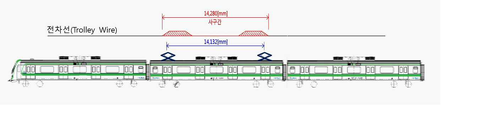
또한 제1전차선(10)과 제2전차선(11) 간의 절연구간은, 무가압 시간 단축을 위한 급전구분시스템의 최소길이 14,280mm로 적용 시 상기 절연구간내에서의 전기철도의 판타그래프간의 간격은 14.132mm인 것을 특징으로 한다.In addition, when the insulation section between the
한편 전차선 급전구분 시스템은, 직류 1,500V 지상부/지하부의 전차선로 에어섹션(Air Section) 구간에서 전기적으로 구분을 위한 것임을 특징으로 한다.On the other hand, the catenary feed classification system is characterized in that it is for electrical classification in the air section section of the catenary line of 1,500V DC above ground/underground.
여기서 전차선 급전구분 시스템은, 전기철도의 최고 속도는 80[km/h]이고, 상기 도시철도 차량의 팬터그래프 간격이 14,132mm로 적용된 경우 사고전류 또는 부하전류에 의한 에어오버(air over)가 발생되지 않으며, 전기차 자동운전조건, 아크지속시간, 전압계전기 동작시간, 차단기 차단시간이 고려되어 제작된 것을 특징으로 한다.Here, in the catenary power supply classification system, when the maximum speed of the electric railway is 80 [km/h] and the pantograph interval of the urban railway vehicle is 14,132 mm applied, air over due to an accident current or load current does not occur. It is characterized in that it is manufactured in consideration of electric vehicle automatic operation conditions, arc duration, voltage relay operation time, and circuit breaker cut-off time.
그리고 상기 전차선 급전구분 시스템의 유효길이 조건은, 직류-직류 급전구분시스템의 경우, A : 아크의 지속시간 40[ms], B : 전압계전기 동작시간 100[ms], C : 차단기 차단시간(IEC 규정 61992-2 ) 20[ms], D : 여유시간 50[ms] 라 할 때, 총 동작시간 = A+B+C+D = 210[ms]이고, 도시철도의 설계속도는 80[km/h]라 하고, 운전속도 80[km/h] 시 적정 유효길이[mm] 조건은 210[ms] × 80[km/h] = 16,800[mm] 시 적용되는 것을 특징으로 한다.And the effective length condition of the catenary feed classification system is, in the case of a DC-DC feed classification system, A: arc duration 40 [ms], B: voltage relay operation time 100 [ms], C: circuit breaker cut-off time (IEC) Regulation 61992-2 ) 20[ms], D: When the spare time is 50[ms], the total operating time = A+B+C+D = 210[ms], and the design speed of the urban railroad is 80[km/ h], and the effective length [mm] condition at the operating speed of 80 [km/h] is applied when 210 [ms] × 80 [km/h] = 16,800 [mm].
본 발명의 실시 예에 따르면 다음과 같은 효과가 있다.According to an embodiment of the present invention, the following effects are obtained.
첫째, 전기철도의 운전속도, 집전장치의 간격, 에어섹션(Air Section) 적정 설치위치를 종합검토하여 급전구분장치 구간에서 섹션오버(Section Over)에 의해 발생하는 전차선 단선을 예방하여 전기철도의 열차 안전운행을 도모할 수 있다.First, by comprehensively reviewing the operating speed of the electric railway, the distance between the current collectors, and the proper installation location of the air section, the electric railway train Safe driving can be promoted.
둘째, 전철화율 및 도시철도 운영구간의 확대는 전차선로 시설의 증가로 이어지며, 전차선로 건설에 필연적으로 나타나는 절연구간이 더욱 확대될 것이고, 이에 따라 전기차 운행조건을 고려한 급전구분장치의 개발에 대한 요구가 증가되는데, 전차선로의 최적 시공, 운영 및 보수 점검 체계를 과학적인 기법을 통하여 구축하여 보다 높은 신뢰도 및 유지보수비용을 최소화시킬 수 있다.Second, the expansion of electrification rate and urban railroad operation section leads to an increase in catenary facilities, and the insulated section that appears inevitably in catenary construction will further expand. As the demand increases, the optimal construction, operation and maintenance inspection system of the catenary can be established through scientific techniques to achieve higher reliability and minimize maintenance costs.
셋째, 지속적으로 성장하는 철도시장에서 현재의 전기차 운영에서는 절연구간은 필연적으로 발생하게 되며, 도시철도 직류급전구간용 급전구분장치의 국산화를 실현하여 부품공급이 원활하게 함으로써 경제성을 높이고, 사고를 미연에 방지하여 전기철도나 도시철도를 이용하는 대국민 신뢰도를 향상할 수 있다.Third, in the continuously growing railway market, insulated sections inevitably occur in the current electric vehicle operation, and by realizing the localization of the power supply classification device for the DC power supply section of urban railways, the supply of parts is facilitated, thereby increasing economic efficiency and preventing accidents. It is possible to improve the public's trust in using electric or urban railroads.
도 1은 차량, 운전 조건을 고려한 급전구분 시스템에서 무가압 길이를 설명하기 위한 도면이다.
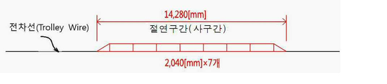
도 2는 지상부 급전구분시스템 구성요건 중 일체형 급전구분시스템 구성을 설명하기 위한 도면이다.
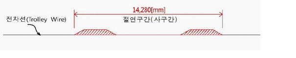
도 3은 지상부 급전구분시스템 구성요건 중 분리형 급전구분시스템 구성을 설명하기 위한 도면이다.
도 4(A)(B)는 본 발명에 따른 전차선 급전구분 시스템을 설명하기 위한 도면이다.
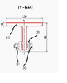
도 5 및 도 6은 본 발명에 따른 전차선 급전구분 시스템에서 전차선으로 이용되는 T-Bar의 단면과 T-Bar의 외주면에 형성되는 절연체의 실시예를 설명하기 위한 도면이다.
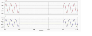
도 7은 기존 전차선의 전압, 전류 파형을 나타낸 도면이다.
도 8은 본 발명에 따른 전차선 급전구분 시스템의 절연체 추가 전차선의 전압, 전류 파형을 나타낸 도면이다.
도 9는 본 발명에 따른 전차선 급전구분 시스템에 모니터링 시스템이 추가된 것을 설명하기 위한 도면이다.
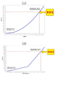
도 10은 전차선에 흐르는 전류 또는 저항과 온도와의 상관관계를 설명하기 위한 도면이다.1 is a view for explaining a non-pressurized length in a power supply classification system in consideration of a vehicle and driving conditions.
2 is a view for explaining the configuration of an integrated power feeding classification system among the elements of the ground portion feeding classification system.
FIG. 3 is a view for explaining the configuration of a separate type power feeding classification system among the elements of the above-ground power feeding classification system.
4 (A) (B) is a view for explaining the catenary feed classification system according to the present invention.
5 and 6 are views for explaining an embodiment of the insulator formed on the outer peripheral surface of the cross section of the T-Bar used as a catenary in the catenary feed classification system according to the present invention.
7 is a diagram showing voltage and current waveforms of an existing catenary.
8 is a view showing the voltage and current waveforms of the insulator additional catenary of the catenary feed classification system according to the present invention.
9 is a view for explaining that a monitoring system is added to the catenary feed classification system according to the present invention.
10 is a view for explaining a correlation between a current or resistance flowing in a catenary and temperature.
본 발명의 바람직한 실시 예를 첨부된 도면에 의하여 상세히 설명하면 다음과 같다.A preferred embodiment of the present invention will be described in detail with reference to the accompanying drawings as follows.
아울러, 본 발명에서 사용되는 용어는 가능한 한 현재 널리 사용되는 일반적인 용어를 선택하였으나, 특정한 경우는 출원인이 임의로 선정한 용어도 있으며 이 경우는 해당되는 발명의 설명부분에서 상세히 그 의미를 기재하였으므로, 단순한 용어의 명칭이 아닌 용어가 가지는 의미로서 본 발명을 파악하여야 함을 밝혀두고자 한다. 또한, 실시예를 설명함에 있어 본 발명이 속하는 기술 분야에 익히 알려져 있고, 본 발명과 직접적으로 관련이 없는 기술 내용에 대해서는 설명을 생략한다. 이는 불필요한 설명을 생략함으로써 본 발명의 요지를 흐리지 않고 더욱 명확히 전달하기 위함이다. In addition, the terms used in the present invention have been selected as widely used general terms as possible, but in certain cases, there are also terms arbitrarily selected by the applicant. It is intended to clarify that the present invention should be understood as the meaning of the term, not the name. In addition, in describing the embodiments, descriptions of technical contents that are well known in the technical field to which the present invention pertains and are not directly related to the present invention will be omitted. This is to more clearly convey the gist of the present invention by omitting unnecessary description.
전기철도의 열차의 안전운행 도모하기 위해서는 DC-DC 절연구분장치 설치조건에 대한 기술분석이 선행되어야 하는데, 전기차 운전조건 분석(자동운전조건, 아크지속시간, 전압계전기 동작시간, 차단기 차단시간, 기타),운전속도를 고려한 유효길이 계산, 전기차 팬터그래프 간격에 따른 절연구분장치 길이 계산 등이 필요하다, In order to promote safe operation of electric railway trains, technical analysis of the installation conditions of the DC-DC insulation classification device must be preceded. ), it is necessary to calculate the effective length considering the driving speed, and to calculate the length of the insulation separator according to the electric vehicle pantograph interval.
또한, 절연구분장치에서의 전차선 용융절손의 원인을 규명하기 위해서는 전차선 마모에 의한 특성변화 분석, 전차선의 전류와 온도와의 상관관계 분석, 부하전류에 의한 온도상승 분석이 필요하다.In addition, in order to identify the cause of the fusion breakage of the catenary in the insulation classifier, it is necessary to analyze the characteristic change due to the wear of the catenary, to analyze the correlation between the current and temperature of the catenary, and to analyze the temperature rise due to the load current.
기능형 절연구분장치에서 지상용의 가공전차선로용 절연구분장치와 지하용의 강체전차선로용 절연구분장치의 개발에 있어 성능시험은 정적·동적압상량 측정, 차량 최소운행 속도 및 정지형 인버터(SIV) 저전압 감지 시간, 절연체 중량에 따른 마모 및 소음 특성, 시범구간 설치 후 신뢰성 시험 등의 성능평가 및 신뢰성 시험이 필요하다. 또한, 개발제품의 성능, 규격 등 세부요구수준은 다음과 같다.In the functional insulation classification system, in the development of an insulation classification system for overhead electric tram lines for ground use and an insulation classification system for underground rigid electric tram lines, the performance test is carried out by measuring static and dynamic pressure rise, minimum vehicle running speed, and stationary inverter (SIV). ) Performance evaluation and reliability tests such as low voltage detection time, wear and noise characteristics according to insulator weight, and reliability test after installation of the trial section are required. In addition, the detailed requirements such as the performance and specifications of the developed product are as follows.
○ 기술사양○ Technical specifications
(가) 기능(a) function
-직류 1,500V 지상부/지하부의 전차선로 에어섹션(Air Section) 구간에서 전기적으로 구분을 위한 절연구분장치의 역할을 하여야 한다.- In the air section section of the direct current 1,500V above ground/underground, it should play the role of an insulating device for electrical division.
- 도시철도 최대속도 열차통과에 지장이 없이 제작되어야 한다.- It must be manufactured without any hindrance to the passage of the maximum speed trains of urban railways.
- 도시철도 차량의 팬터그래프 간격에 따른 사고전류 또는 부하전류에 의한 air over가 발생되지 않도록 제작되어야 한다.- It must be manufactured so that air over does not occur due to accident current or load current according to the pantograph interval of urban railroad vehicles.
- 전기차 자동운전조건, 아크지속시간, 전압계전기 동작시간, 차단기 차단시간 등을 고려하여 제작되어야 한다.- It must be manufactured in consideration of electric vehicle automatic operation conditions, arc duration, voltage relay operation time, circuit breaker cut-off time, etc.
(나) 필요조건(B) Requirements
- 절연체의 재질은 실리콘(silicon) 수지계열의 FRP를 사용하여야 하며, 내마모성 및 내열성이 우수하여야 한다.- For the material of the insulator, silicone resin-based FRP must be used, and it must have excellent abrasion resistance and heat resistance.
- 절연체 및 취부금구는 기존 FRP제 섹션인슐레이터 및 절연구분장치를 대체하여 설치할 수 있도록 설계/제작되어야 하며, 취부금구의 기계적 성능은 동등 이상으로 한다.- Insulators and mounting brackets must be designed/manufactured to replace the existing FRP section insulators and insulating separators, and the mechanical performance of the mounting brackets must be equal or higher.
- 각각의 절연체 성능 및 조립 후의 성능은 기존 사용품과 비교하여 동등 이상이어야 한다.- The performance of each insulator and the performance after assembly should be equal to or higher than that of the existing product.
- 전기차 통과 시 정적·동적압상량은 기존 에어섹션(air section)과 동등이상이어야 하며, 정지형 인버터(SIV) 저전압 감지 시간을 고려하여 제작되어야 한다.- When passing an electric vehicle, the static and dynamic pressure rise must be equal to or greater than that of the existing air section, and it must be manufactured in consideration of the static inverter (SIV) low voltage detection time.
- 절연체 중량에 따른 마모 및 아크발생량 등이 기존 air section과 동등이상이어야 한다- Abrasion and arc generation according to the weight of the insulator should be equal to or higher than that of the existing air section.
(다) 구성 (C) Composition
- 구성은 절연체 및 조립금구로 구성된다.- The composition consists of an insulator and an assembly bracket.
○ 검사 및 시험○ Inspection and test
(가) 공장 시험, 형식시험 및 현장시험이 수행된다. 각 시험의 절차사양은 연구수행중 작성되며, 기존 섹션인슐레이터를 기준으로 작성한다.(A) Factory test, type test and field test are carried out. The procedural specifications of each test are prepared during research and are based on the existing section insulator.
(나) 공장시험 (B) Factory test
- 공장시험은 제작자 장소에서 성능을 만족하는지 확인하는 시험하는 것을 말한다. - Factory test refers to testing to confirm that the performance is satisfied at the manufacturer's place.
(다) 형식시험(C) Type test
- 형식시험은 현장시험의 전 단계로, 요구하는 성능사양을 만족하는지 확인하기 위하여 공인기관에서 수행하는 시험을 말한다. - The type test is the pre-stage of the field test, and it refers to a test performed by an accredited organization to check whether the required performance specifications are satisfied.
(라) 현장시험(D) Field test
- 현장시험은 실제노선에서 설치하여 기능을 만족하는지 확인하기 위한 시험으로, 일정기간 설치/운영하여 기능에 문제가 없는지 확인한다.- The field test is a test to check whether the function is satisfied by installing it on the actual route.
이를 정리하면 다음 표 1과 같다.This is summarized in Table 1 below.

섹션(SECTION:구분장치)은 전차선의 급전 계통을 구분하여 전차선의 일부분에 사고가 발생하는 경우 또는 일상의 보수작업을 위하여 정전작업이 필요한 경우 등에 급전 정지 구간을 한정하고 다른 구간의 열차 운전 확보를 목적으로 한 설비로서 급전 구분구간에 적용되는 에어섹션(Air Section) 등이 있다.Section (Section device) divides the power supply system of the catenary to limit the section where the power supply is stopped and secure the operation of the train in other sections when an accident occurs in a part of the catenary or when a power outage is required for daily maintenance work. As facilities for the purpose, there is an air section applied to the power supply division section.
그리고 에어섹션은 급전구분구간이 서로 중첩되는 공간을 공기에 의해 전기적으로 분리하는 것으로 전차선로에 일정한 간격으로 설치된다.In addition, the air section is installed at regular intervals on the catenary by electrically separating the space where the feed classification sections overlap with each other by air.
판타그래프(PANTOGRAPH)는 지붕에 장치한 마름모꼴로 접을 수 있게 짠 틀 위에 가선(架線)과 접촉하는 집전부를 갖춘 것인데 스프링 또는 압축공기의 힘으로 가선이 밀착하도록 밀어 올리는 방식을 이용하고, 전자를 스프링상승식, 후자를 공기상승식이라고 한다.The PANTOGRAPH is equipped with a current collector in contact with the overhead wire on a lozenge-shaped foldable frame mounted on the roof. Spring rising type, the latter is called air rising type.
섹션오버(Section Over) 현상은, 급전구분구간에 열차가 정차할 때 판타그래프에 의하여 양 급전구분 구간 전차선에 접촉되어 에어섹션을 전기적으로 연결시킨 상태로서 양쪽 변전실의 병렬급전 구간에서 에어섹션에 1량의 차량에 설치된 2개의 팬토그래프가 철도차량 내부의 전기적인 폐회로에 의해 단락되어 전동차의 고장이나 전류의 급격한 변화로 인해 아크가 발생함으로써 전차선의 용선 및 화재발생 등의 우려가 있는 것이다.The section over phenomenon is a state in which the air section is electrically connected by contacting the catenary in both feeding division sections by the phantagraph when the train stops in the power feeding section, and in the parallel feeding section of both substations, the air section is 1 in the air section. Two pantographs installed in a large number of vehicles are short-circuited by an electric closed circuit inside the railroad car, and arcs are generated due to a breakdown of the train or a sudden change in current, which may cause charring of the catenary and the occurrence of fire.
이러한 에어섹션(Air Section)은 집전부분의 전차선에 절연물을 삽입하지 않고 절연하여야 할 전차선 상호 평행부분을 일정한 간격으로 유지하여 공기의 절연을 이용한 구분장치이다. 본선에서 동상의 구분용으로 사용한다.This air section is a classification device using air insulation by maintaining parallel parts of the electric wires to be insulated at regular intervals without inserting insulation into the electric wires of the current collecting part. It is used to distinguish statues in the finals.
에어섹션은 서울메트로의 경우 1~4 호선에 총 90개소(본선 : 84)가 설치되어 있는데, 지상부에 14개소(본선 : 12), 지하부에 76개소(본선 : 72)가 있다.In the case of Seoul Metro, there are a total of 90 air sections (main line: 84) on
전기철도가 전류에 의해 생기는 열량 Q[cal]는 전류의 세기 I[A]의 제곱, 도체의 전기적 접촉저항R[Ω], 전류를 통과하는 시간 t [sec]에 비례한다.The amount of heat Q[cal] generated by the electric rail current is proportional to the square of the current strength I[A], the electrical contact resistance R[Ω] of the conductor, and the time t [sec] for passing the current.
전차선의 온도상승에 대한 이론적 계산을 간략히 설명하면, 에어섹션 구간의 전차선에 3,000A 인가 시 발생되는 열량은 171.8kcal로, 전차선 재질의 용융점은 1,803℃이고, 전차선(Cu 170mm2) 단위중량 : 1,511g/m이며, 비열은 0.0924cal/g ℃이다. 그에 따라 전차선 1m에 가해지는 온도변화량은 1,231℃로, 두 도체 간 단락 시 아크발생 최저전압은 15~20V이다.Briefly explaining the theoretical calculation of the temperature rise of the catenary, when 3,000A is applied to the catenary in the air section section, the amount of heat generated is 171.8kcal, the melting point of the catenary material is 1,803℃, and the catenary (Cu 170mm 2 ) unit weight: 1,511 g/m, and the specific heat is 0.0924 cal/g °C. Accordingly, the amount of temperature change applied to 1m of the catenary is 1,231℃, and the minimum voltage for arc generation in case of a short circuit between two conductors is 15~20V.
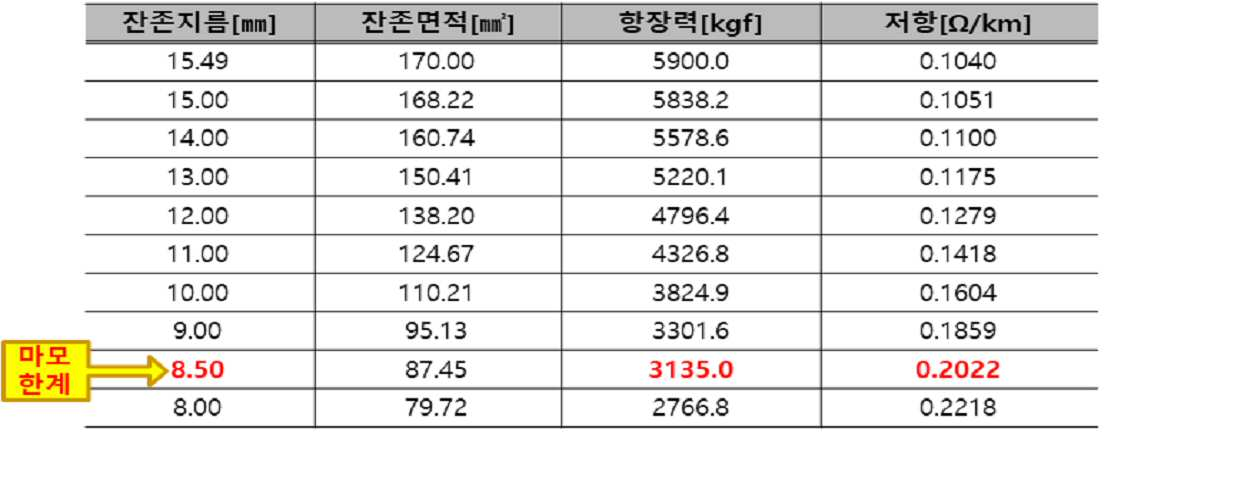
전차선은 판타그래프의 습동에 따라 전기적, 기계적으로 마모되고, 전차선 마모 시 단면적의 감소에 다른 전차선 항상력 저하로 단선이 우려되고, 마모한계는 8.5mm로 설정하고 있는데 이는 표 2와 같이 항장력을 고려한 것이다.The catenary is worn electrically and mechanically according to the movement of the pantograph, and when the catenary is worn, there is a concern about disconnection due to a decrease in the cross-sectional area and a decrease in the stability of the other catenary, and the wear limit is set at 8.5mm, which is will be.
전차선에 흐르는 전류와 온도와의 상관관계를 간단히 설명하면, 도 10a와 같이 단방향 차단기 투입 지속시간을 35초, 전차선 저항을 0.1279Ω/㎞로 가정하면 전차선 전류 10.73kA이고, 온도는 1,083℃로 전차선 용융점에 도달(단선)하게 된다.Briefly explaining the correlation between the current flowing in the catenary and the temperature, assuming that the one-way circuit breaker input duration is 35 seconds and the catenary resistance is 0.1279Ω/km, as shown in FIG. 10A, the catenary current is 10.73kA, and the temperature is 1,083℃. The melting point is reached (disconnection).
그리고 전차선에 흐르는 저항과 온도와의 상관관계를 간단히 설명하면, 도 10b와 같이 단방향 차단기 투입 지속시간을 35초, 전차선 전류를 5,000A로 가정 시 전차선 저항 4.12Ω이고, 온도는 1,083℃로 전차선 용융점에 도달(단선)된다.And to briefly explain the correlation between the resistance flowing in the catenary and the temperature, assuming that the one-way circuit breaker input duration is 35 seconds and the catenary current is 5,000A, as shown in FIG. 10b, the catenary resistance is 4.12Ω, and the temperature is 1,083℃. is reached (disconnected).
한편 차량 운전조건을 고려한 급전구분 시스템에서, 직류-직류 급전구분시스템의 길이계산 조건은 A: 아크의 지속시간 40ms, B: 전압계전기 동작시간 100ms, C: 차단기 차단시간(IEC 규정 61992-2) 20ms, D: 여유시간 50ms라 할 때, 총 동작시간(A+B+C+D)은 210ms가 된다.On the other hand, in the power supply classification system considering vehicle driving conditions, the length calculation conditions of the DC-DC power supply classification system are: A: arc duration 40ms, B: voltage relay operation time 100ms, C: circuit breaker cut-off time (IEC regulation 61992-2) 20ms, D: Assuming that the spare time is 50ms, the total operation time (A+B+C+D) is 210ms.
이러한 전기철도 중 도시철도 설계속도를 80km/h라 하고 운전속도 80km/h 시 적정 유효길이[mm]의 조건은 210[ms]×80[km/h] = 16,800[mm]이다.Among these electric railroads, the design speed of urban railroads is 80km/h, and when the operating speed is 80km/h, the optimal effective length [mm] is 210[ms]×80[km/h] = 16,800[mm].
무가압 시간 단축을 위한 급전구분시스템 최소길이[mm] 적용은 14,280[mm]이다. 이때, 여유길이[mm]는 14,280(급전구분시스템 길이)-14,132(판타간격) = 148[mm](차량 SIV 저전압감지 최소시간을 고려한 길이 적용)이다.The minimum length [mm] of the feed classification system for reducing the no-pressurization time is 14,280 [mm]. At this time, the extra length [mm] is 14,280 (length of power supply classification system) -14,132 (fantasy interval) = 148 [mm] (length applied considering the minimum time for vehicle SIV low voltage detection).
도 1은 일반적인 전기차량, 운전 조건을 고려한 급전구분 시스템에서 무가압 길이를 설명하기 위한 도면이고, 도 2는 지상부 급전구분시스템 구성요건 중 일체형 급전구분시스템 구성을 설명하기 위한 도면이며, 도 3은 지상부 급전구분시스템 구성요건 중 분리형 급전구분시스템 구성을 설명하기 위한 도면이다.1 is a diagram for explaining the unpressurized length in a power supply classification system considering general electric vehicles and driving conditions, FIG. 2 is a diagram for explaining the configuration of an integrated power supply classification system among the above-ground part supply classification system components, and FIG. 3 is It is a diagram for explaining the configuration of a separate type power supply classification system among the elements of the above-ground power supply classification system.
최적의 급전구분시스템 설계 시 전기차량용 SIV 저전압 감지 최소시간 10[ms] 범위 이내로 요구되어, 급전구분시스템 설치위치 여건에 따라 전동차의 운전속도를 고려하여 SIV장치의 감지조건에 적합한 무가압 길이 선정이 중요하다.When designing the optimal power supply classification system, the minimum SIV low voltage detection time for electric vehicles is required to be within the range of 10 [ms]. It is important.
이러한 무가압 길이는 This unpressurized length is
148[mm]×10-3×3,600[sec]÷55[km/h] = 9.68[ms]148[mm]×10 -3 ×3,600[sec]÷55[km/h] = 9.68[ms]
이다.to be.
이에 따른 설계요구조건은, Accordingly, the design requirements are:
① 차량 VVVF 및 SIV(Static Inverter : 전원장치)의 저전압 감지 최소시간 : 10[ms] ① Minimum time to detect low voltage of vehicle VVVF and SIV (Static Inverter: power supply): 10[ms]
② 최소 차량속도 : V=0.148[m]÷10[ms] = 14.8[ms] → 14.8×3.6 = 53.28[km/h] ② Minimum vehicle speed: V=0.148[m]÷10[ms] = 14.8[ms] → 14.8×3.6 = 53.28[km/h]
③ 전기적 절연이격거리에 부합조건 : 표준 250mm, 최소 70mm, 순시 30mm③ Conditions for electrical insulation separation distance: standard 250mm, minimum 70mm, instantaneous 30mm
④ 구분장치 내 차량이 정차하여 저 전압이 발생할 km당 확률은 0.0148% 이내이다.④ The probability per km that a vehicle in the classification device will stop and low voltage will occur is within 0.0148%.
지상부 급전구분시스템 구성요건 중 일체형 급전구분시스템 구성을 설명하기 위한 도 2를 보면, Referring to FIG. 2 for explaining the configuration of the integrated power feeding classification system among the above-ground power feeding classification system components,
정상적인 선로 정적 압상량(Y)은 The normal line static raise (Y) is
Y = s·p/4T = (50×6)/(4×3,000) ×1,000 = 25[mm]Y = s p/4T = (50×6)/(4×3,000) ×1,000 = 25[mm]
S : 경간 50[m], P : 압상력 6[kg/㎠], T : 가선장력 3[Ton].S: Span 50[m], P: Pressing force 6[kg/cm2], T: Wire tension 3[Ton].
그리고 절연체 설치 시 정적 압상량(Y)은,And when the insulator is installed, the static lifting amount (Y) is,
FRP 절연체 중량 : 수지제 4kg + 체결 이음금구 1kg = 5[kg] / 5kg×7조 = 35[kg], 전차선 단위중량 : 1,511[g/m], 절연체 단위중량 : 2500[g/m](참고사항 : 절연체 중량에 의한 국부마모 발생(교체주기 허용값 : 5mm 이상))이라 할 때,FRP insulator weight: resin 4kg + fastening joint 1kg = 5[kg] / 5kg×7 sets = 35[kg], unit weight of catenary: 1,511[g/m], unit weight of insulator: 2500[g/m]( Note: When local wear occurs due to the weight of the insulator (permissible value for replacement cycle: 5mm or more)),
정적 압상량 Y =(1,511×50)/[(1,511×35.65)+(2,500×4.28)]×25 = 21[mm]이다.Static lifting amount Y = (1,511 × 50)/[(1,511 × 35.65) + (2,500 × 4.28)] × 25 = 21 [mm].
그러나 이러한 경우 동적 압상량에 대한 추종성 저하로 절연체 국부마모 발생, 마찰소음증가, 접속점 연속으로 안전성 결여, 복구시간 지연 등 예상되는 문제가 발생될 수 있다.However, in this case, expected problems such as local abrasion of insulator, increase in friction noise, lack of safety in continuous connection points, delay in recovery time, etc.
한편 지상부 급전구분시스템 구성요건 중 분리형 급전구분시스템은 도 3에 나타낸 바와 같이, On the other hand, as shown in FIG. 3, the separate type feed classification system among the elements of the above-ground feed classification system is,
정적 압상량 Y = (1,511×50)/[(1,511×46) + (2,500×4)] ×5 = 23.7[mm]Static lifting amount Y = (1,511×50)/[(1,511×46) + (2,500×4)] ×5 = 23.7[mm]
이고, 동적 압상량 : 운전속도 100[km/h] 미만에서 정적압상량의 약 3배인데, 절연체의 자중 감소에 따른 판타 압상력에 대한 추종성이 양호하고, 접속점이 적어 집전마찰 소음이 감소한다.and dynamic lifting amount: about 3 times the static lifting amount under the operating speed of less than 100 [km/h]. .
도 4는 본 발명에 따른 전차선 급전구분 시스템을 설명하기 위한 도면이고, 도 5는 전차선으로 이용되는 T-Bar의 단면도이며, 도 6은 T-Bar의 외주면에 형성되는 절연체의 실시예를 설명하기 위한 도면이고, 도 7 기존 전차선의 전압, 전류 파형을 나타낸 도면이고, 도 8은 본 발명에 따른 전차선 급전구분 시스템의 절연체 추가 전차선의 전압, 전류 파형을 나타낸 도면이다.4 is a view for explaining a catenary feed classification system according to the present invention, FIG. 5 is a cross-sectional view of a T-Bar used as a catenary, and FIG. 6 is an embodiment of an insulator formed on the outer peripheral surface of the T-Bar. 7 is a view showing the voltage and current waveforms of the existing catenary, and FIG. 8 is a view showing the voltage and current waveforms of the insulator-added catenary of the catenary feed classification system according to the present invention.
본 발명에 따른 전차선 급전구분 시스템은 도 4 내지 도 6에 나타낸 바와 같은데, 미리 설정된 절연구간(사구간)에 구성되는 것으로, 절연구간은 급전구분구간이 서로 중첩되는 공간을 공기에 의해 전기적으로 분리하는 것으로 전차선로에 일정간격으로 설치된다. The catenary feed classification system according to the present invention is as shown in FIGS. 4 to 6 , and is configured in a preset insulation section (four section), and the insulation section electrically separates the space where the feed classification sections overlap with each other by air. It is installed at regular intervals on the tramway.
이러한 전차선 급전구분 시스템은, 직류 1,500V 지상부/지하부의 전차선로 에어섹션(Air Section) 구간에서 전기적으로 구분을 위한 절연구분장치의 역할을 하여야 하고, 도시철도 최대속도 열차통과에 지장이 없이 제작되어야 하며, 도시철도 차량의 팬터그래프 간격에 따른 사고전류 또는 부하전류에 의한 air over가 발생하지 않도록 제작되어야 한다. 또한, 전기차의 자동운전조건, 아크지속시간, 전압계전기 동작시간, 차단기 차단시간 등을 고려하여 제작되어야 한다.Such a catenary feed classification system should play a role of an insulating classification device for electrical classification in the air section section of the electric 1,500V DC aboveground/underground part, and it should be manufactured without any obstacles to the passage of the maximum speed train of the urban railway. It should be manufactured so that air over does not occur due to accident current or load current according to the pantograph interval of urban railroad vehicles. In addition, it should be manufactured in consideration of the electric vehicle's automatic operation conditions, arc duration, voltage relay operation time, circuit breaker cut-off time, etc.
각각의 판타그래프는 폭이 332mm이고, 여유폭은 68mm이며, 절연길이는 400mm인 경우에, 제1전차선(10)과 제2전차선(11) 간의 절연구간은 14,280mm로 구성되고, 상기 절연구간내에서의 판타그래프간의 간격은 14.132mm이다. 물론 이러한 절연구간과 판타그래프간의 간격은 하나의 예일 뿐 변경될 수 있다. When each pantograph has a width of 332 mm, an extra width of 68 mm, and an insulation length of 400 mm, the insulation section between the
이때, 제1전차선(10)과 제2전차선(11)에는 절연구간사이에서 각각 FRP(fiber reinforced plastics)를 포함하는 절연체가 각각 구성되며, 이러한 절연체(20)는 400 내지 600mm의 너비로 구성될 수 있다.At this time, insulators including fiber reinforced plastics (FRP) are respectively configured in the
이를 보다 상세히 설명하면 도 5 및 도 6에서는 전차선을 구성하는 T-Bar가 도시되어 있는데, 이러한 T-Bar의 외주면에 FRP와 같은 절연체(20)가 결합된다. To describe this in more detail, the T-Bar constituting the catenary is shown in FIGS. 5 and 6 , and an
이러한 절연체(20)는 절연구간 일측과 타측 각각에서 T-Bar의 외주면에 400 내지 600mm의 길이로 절연구간 일측과 타측의 각각에서 절열구간 내측으로 형성되며, T-Bar의 외주면을 감싸도록 형성된다. This
그리고 절연체(20)는 T-Bar의 외주면에서 외측으로 5 내지 10mm의 두께로 형성된다. 또한 절연체(20)는 T-Bar의 외측에서 내측으로 삽입된 후 절연체(20)에서 T-Bar의 양측에 미리 설정된 소정간격을 갖고 복수의 볼트(30)와 너트(31)를 이용하여 체결될 수 있는데, 두 개의 볼트와 너트를 이용하여 체결한다고 하였을 경우 절연체(20)에는 볼트체결공(볼트체결부)(21)이 형성되면 볼트 체결공(21)간의 거리를 250mm를 갖도록 구성될 수 있다. 물론 이러한 볼트체결은 하나의 예일 뿐 T-Bar와 절연체(20)의 체결방식을 특별히 한정할 필요는 없다. And the
본 발명에서는 절연체(20)의 재질은 절연성, 내마모성 및 내열성이 우수하 판타그래프와 습동이 양호한 실리콘(silicon) 수지계열과 FRP를 사용하였다. 이는 전기차 통과시 정적, 동적압상량은 기존 air section과 동등 이상이어야 하며, 정지형 인버터(SIV) 저전압 감지 시간을 고려하여 제작된 것이다. 또한 절연체(20) 중량에 따른 마모 및 아크발생량 등이 기존 에어섹션(air section)과 동등 이상이어야 하며, 앞에서 설명한 표 1에서와 같은 조건을 만족하는 것이 바람직하다. In the present invention, as the material of the
이러한 상기 절연체(20)는 상기T-Bar의 외주면에 접하는 실리콘계 수지층(미도시);과 및 상기 실리콘계 수지층의 외면에 형성되는 FRP보강층(미도시);을 포함하여 구성될 수 있다. 상기 절연체(20)가 실리콘계 수지층(미도시);과 FRP보강층(미도시)으로 구성됨으로써, 현저한 절연성뿐만 아니라, 내마모성 및 내열성까지 기대할 수 있다.The
상기 실리콘계 수지층의에 사용되는 실리콘계 수지는 실리콘 계열이면 특별히 한정되지 않으나, 전기 절연성, 내열성, 약간의 취성, 내후성을 갖는 것을 이용함이 바람직하다.The silicone-based resin used in the silicone-based resin layer is not particularly limited as long as it is silicone-based, but it is preferable to use one having electrical insulation, heat resistance, slight brittleness, and weather resistance.
상기 실리콘계 수지층에 의해 절연체(20)는 약간의 유연성을 갖게 되어, 외부의 충격이나 진동을 흡수하게 된다. 즉, 진동이나 충격을 감쇄시킬 수 있는 효과가 있다.Due to the silicone-based resin layer, the
방법에 따라서, 상기 실리콘계 수지층은 (A) 5-비닐비시클로[2.2.1]헵트-2-엔, 6-비닐비시클로[2.2.1]헵트-2-엔 또는 이들 둘의 조합과 1,3,5,7-테트라메틸시클로테트라실록산과의 부가 반응물, (B) 규소 원자에 결합한 알케닐기를 1분자 중에 2개 이상 갖는 실록산계 화합물, 및 (C) 히드로실릴화 반응 촉매를 포함하도록 하여, 내구성을 현저하게 개선할 수 있다.According to the method, the silicone-based resin layer comprises (A) 5-vinylbicyclo[2.2.1]hept-2-ene, 6-vinylbicyclo[2.2.1]hept-2-ene, or a combination of both and 1 , an addition reaction product with 3,5,7-tetramethylcyclotetrasiloxane, (B) a siloxane-based compound having two or more alkenyl groups bonded to a silicon atom in one molecule, and (C) a hydrosilylation reaction catalyst. Thus, durability can be remarkably improved.
또한, 상기 실리콘계 수지층은 두께가 얇을수록 실리콘계 수지층의 두께 균일도가 더욱 확보되기 때문에 경화 후 10~500㎛ 정도가 바람직하다.In addition, since the thickness uniformity of the silicone-based resin layer is further ensured as the thickness of the silicone-based resin layer decreases, the thickness of the silicone-based resin layer is preferably about 10 to 500 μm after curing.
상기 FRP 보강층는 내구성과 내충격성 및 내마모성이 우수하며, 녹슬지 않고, 절연 재질로 열에 변형되지 않으므로, 절연체(20)의 물성과 기계적 강도를 현저히 개선할 수 있는 효과가 있다.The FRP reinforcing layer has excellent durability, impact resistance and abrasion resistance, does not rust, and is not deformed by heat due to an insulating material, so that it is possible to significantly improve the physical properties and mechanical strength of the
이때, 상기 FRP 보강층은 비닐에스터수지 38~54중량%, 저온경화제 0.5~2.8중량%, 고온경화제 0.3~2.5중량%, 내부이형제 0.9~1.5중량%, 표면처리제 0.3~0.8중량%, 저수축제 0.7~2.5중량%, 수산화알루미늄 0.4~4.2중량%, 수산화마그네슘 0.4~3.9중량%, 멜라민 2.8~5.2중량%, 유리섬유 15~24중량%, 탄소섬유 12~18중량% 및 폴리아미드 8~15중량%를 포함하여 구성되는 것이 바람직하다.At this time, the FRP reinforcing layer is 38 to 54% by weight of vinyl ester resin, 0.5 to 2.8% by weight of low temperature curing agent, 0.3 to 2.5% by weight of high temperature curing agent, 0.9 to 1.5% by weight of internal release agent, 0.3 to 0.8% by weight of surface treatment agent, 0.7% by weight of low shrinkage agent ~2.5 wt%, aluminum hydroxide 0.4~4.2 wt%, magnesium hydroxide 0.4~3.9 wt%, melamine 2.8~5.2 wt%, glass fiber 15~24 wt%, carbon fiber 12~18 wt% and polyamide 8~15 wt% It is preferable to include %.
도 7은 기존 전차선의 전압, 전류 파형을 나타낸 도면이고, 도 8은 본 발명에 따른 전차선 급전구분 시스템의 절연체 추가 전차선의 전압, 전류 파형을 나타낸 도면으로, 본 발명 전차선(10, 11)의 외주면에 절연체(20)가 형성된 경우 기본 전차선의 전압, 전류 파형은 전차선(10, 11)의 절연구간에 진입 후 기존 장치에서는 아크가 발생되고 본 발명에서는 아크의 발생없이 바로 안정되는 것을 보여주고 있다.7 is a view showing the voltage and current waveforms of the existing catenary, and FIG. 8 is a view showing the voltage and current waveforms of the insulator additional catenary of the catenary feeding classification system according to the present invention. The outer peripheral surface of the catenary of the present invention (10, 11) When the
도 9는 본 발명에 따른 전차선 급전구분 시스템에 모니터링 시스템이 추가된 것을 설명하기 위한 도면이다.9 is a view for explaining that a monitoring system is added to the catenary feed classification system according to the present invention.
본 발명에 따른 전차선 급전구분 시스템에 모니터링 시스템이 추가된 실시예는 전기철도 운행 시 절연구간에서 팬터그래프 접촉상태의 영상을 카메라(40)를 통해 모니터링하고, 부하전류 및 사고발생 시 데이터를 모니터링 데이터 수집장치(50)를 통해 수집하고, 이를 데이터 저장/표시 분석장치(60)를 통해 분석하도록 한다. 이를 위하여 모니터링 데이터 수집장치(50)에서는 복수의 카메라(40)를 통해 수집된 영상과 절연구간내의 전차선(10, 11)이나 팬터그래프로부터 부하전류나 사고전류를 수집한 후, 데이터 저장/표시 분석장치(60)로 전송한다. 데이터 저장/표시 분석장치(60)는 PC나 서버로 구성되어 모니터링 데이터 수집장치(50)에서 수집된 영상 데이터와 부하전류나 사고전류 데이터를 메모리나 데이터베이스에 저장한 후 이를 분석함으로써 절연구간내에 구성된 전차선 급전구분 시스템을 구성하는 전차선(10, 11)과 절연체(20)에 의한 급전구분 시스템의 안정성과 기능이 표 1에서와 같은 조건을 만족하는지를 확인할 수 있다.In an embodiment in which a monitoring system is added to the catenary power supply classification system according to the present invention, the image of the pantograph contact state in the insulating section during operation of the electric rail is monitored through the
이상과 같은 예로 본 발명을 설명하였으나, 본 발명은 반드시 이러한 예들에 국한되는 것이 아니고, 본 발명의 기술사상을 벗어나지 않는 범위 내에서 다양하게 변형 실시될 수 있다. 따라서 본 발명에 개시된 예들은 본 발명의 기술 사상을 한정하기 위한 것이 아니라 설명하기 위한 것이고, 이러한 예들에 의하여 본 발명의 기술 사상의 범위가 한정되는 것은 아니다. 본 발명의 보호 범위는 아래의 청구범위에 의하여 해석되어야 하며, 그와 동등한 범위 내에 있는 모든 기술 사상은 본 발명의 권리범위에 포함되는 것으로 해석되어야 한다. Although the present invention has been described with the above examples, the present invention is not necessarily limited to these examples, and various modifications may be made within the scope without departing from the technical spirit of the present invention. Therefore, the examples disclosed in the present invention are not intended to limit the technical spirit of the present invention, but to explain, and the scope of the technical spirit of the present invention is not limited by these examples. The protection scope of the present invention should be construed by the following claims, and all technical ideas within the scope equivalent thereto should be construed as being included in the scope of the present invention.
10, 11: 전차선
20 : 절연체
30 : 볼트
31 : 너트
40 : 카메라
50 : 모니터링 데이터 수집장치
60 : 데이터 저장/표시 분석장치10, 11: catenary
20: insulator
30: bolt
31: nut
40 : camera
50: monitoring data collection device
60: data storage/display analysis device
Claims (8)
상기 절연구간내의 상기 제1전차선(10)과 제2전차선(11)을 구성하는 T-Bar의 외주면 각각에 상기 T-Bar의 외주면을 감싸도록 형성되되, 상기 절연구간의 내측방향으로 상기 T-Bar에 미리 설정된 소정의 길이로 형성되는 절연체(20);를 포함하여 형성됨을 특징으로 하는 전차선 급전구분 시스템.
미리 설정된 절연구간내에 구성되는 것으로, 상기 절연구간내에 구성된 제1전차선(10)과 제2전차선(11); 및
상기 절연구간내의 상기 제1전차선(10)과 제2전차선(11)을 구성하는 T-Bar의 외주면 각각에 상기 T-Bar의 외주면을 감싸도록 형성되되, 상기 절연구간의 내측방향으로 상기 T-Bar에 미리 설정된 소정의 길이로 형성되는 절연체(20);를 포함하여 형성됨을 특징으로 하는 전차선 급전구분 시스템.
a first tram line 10 and a second tram line 11 configured in a preset insulating section and configured in the insulating section; and
It is formed to surround the outer circumferential surface of the T-Bar on each of the outer circumferential surfaces of the T-Bar constituting the first tram line 10 and the second tram line 11 in the insulation section, and the T-Bar in the inner direction of the insulation section An insulator (20) formed in a predetermined length in advance on the bar;
상기 절연체(20)는 상기 절연체(20)의 중량에 따른 마모 및 아크발생량과 전기철도 통과시 정적, 동적압상량은 급전구분구간이 서로 중첩되는 공간을 공기에 의해 전기적으로 분리하는 에어섹션(air section)과 동등 이상의 절연체인 것을 특징으로 하는 전차선 급전구분 시스템.
The method according to claim 1,
The insulator 20 is the amount of wear and arc generation according to the weight of the insulator 20, and the static and dynamic pressure rise when passing through an electric rail. section) and an insulator equivalent to or higher than that of a catenary feed classification system.
상기 절연체(20)는 상기 T-Bar의 외주면에 접하는 실리콘계 수지층;과 및 상기 실리콘계 수지층의 외면에 형성되는 FRP보강층;을 포함하고, 상기 절연체(20)는 상기 T-Bar와 볼트체결됨을 특징으로 하는 전차선 급전구분 시스템.
The method according to claim 1,
The insulator 20 includes a silicone-based resin layer in contact with the outer circumferential surface of the T-Bar; and an FRP reinforcing layer formed on the outer surface of the silicone-based resin layer, wherein the insulator 20 is bolted to the T-Bar Characterized by a catenary feed classification system.
상기 절연체(20)는 상기 T-Bar의 외주면에서 외측으로 5 내지 15mm의 두께와 상기 절연구간의 양측 외측에서 내측의 상기 T-Bar의 외주면에 400 내지 600mm의 너비로 형성됨을 특징으로 하는 전차선 급전구분 시스템.
The method according to claim 1,
The insulator 20 is formed in a thickness of 5 to 15 mm from the outer peripheral surface of the T-Bar to the outside and a width of 400 to 600 mm on the outer peripheral surface of the T-Bar inside from both sides of the insulation section to the inside. division system.
상기 제1전차선(10)과 제2전차선(11) 간의 절연구간은,
무가압 시간 단축을 위한 급전구분시스템의 최소길이 14,280mm로 적용 시
상기 절연구간내에서의 전기철도의 판타그래프간의 간격은 14.132mm인 것을 특징으로 하는 전차선 급전구분 시스템.
The method according to claim 1,
The insulating section between the first tram line 10 and the second tram line 11 is,
When applying the minimum length of 14,280mm of the feed classification system to shorten the no-pressurization time
The catenary feed classification system, characterized in that the interval between the pantographs of the electric railway within the insulation section is 14.132mm.
상기 전차선 급전구분 시스템은,
직류 1,500V 지상부/지하부의 전차선로 에어섹션(Air Section) 구간에서 전기적으로 구분을 위한 것임을 특징으로 하는 전차선 급전구분 시스템.
The method according to claim 1,
The catenary feed classification system is
A catenary power supply classification system, characterized in that it is for electrical classification in the air section section of the catenary line in the DC 1,500V above ground/underground.
상기 전차선 급전구분 시스템은,
전기철도의 최고 속도는 80[km/h]이고,
상기 전기철도의 차량의 팬터그래프 간격이 14,132mm로 적용된 경우 사고전류 또는 부하전류에 의한 에어오버(air over)가 발생되지 않으며,
전기차 자동운전조건, 아크지속시간, 전압계전기 동작시간, 차단기 차단시간 이 고려되어 제작된 것을 특징으로 하는 전차선 급전구분 시스템.
The method according to claim 1,
The catenary feed classification system is
The maximum speed of the electric railway is 80 [km/h],
When the pantograph interval of the vehicle of the electric railway is applied to 14,132 mm, air over by accident current or load current does not occur,
Electric vehicle automatic operation condition, arc duration, voltage relay operation time, and circuit breaker cut-off time are taken into consideration.
상기 전차선 급전구분 시스템의 유효길이 조건은,
직류-직류 급전구분시스템의 경우,
A : 아크의 지속시간 40[ms], B : 전압계전기 동작시간 100[ms], C : 차단기 차단시간(IEC 규정 61992-2 ) 20[ms], D : 여유시간 50[ms] 라 할 때,
총 동작시간 = A+B+C+D = 210[ms]이고,
상기 전기철도의 설계속도는 80[km/h]라 하고, 운전속도 80[km/h] 시 적정 유효길이[mm] 조건은 210[ms] × 80[km/h] = 16,800[mm] 시 적용되는 것을 특징으로 하는 전차선 급전구분 시스템.8. The method of claim 7,
The effective length condition of the catenary feed classification system is,
In case of DC-DC feed classification system,
A: Arc duration 40[ms], B: Voltage relay operation time 100[ms], C: Circuit breaker cut-off time (IEC regulation 61992-2 ) 20[ms], D: Spare time 50[ms] ,
Total operating time = A+B+C+D = 210[ms],
It is assumed that the design speed of the electric railway is 80 [km/h], and when the operating speed is 80 [km/h], the appropriate effective length [mm] condition is 210 [ms] × 80 [km/h] = 16,800 [mm] Catenary line feed classification system, characterized in that it is applied.
Priority Applications (1)
| Application Number | Priority Date | Filing Date | Title |
|---|---|---|---|
| KR1020210055092A KR102469395B1 (en) | 2021-04-28 | 2021-04-28 | Catenary feeding division system |
Applications Claiming Priority (1)
| Application Number | Priority Date | Filing Date | Title |
|---|---|---|---|
| KR1020210055092A KR102469395B1 (en) | 2021-04-28 | 2021-04-28 | Catenary feeding division system |
Publications (2)
| Publication Number | Publication Date |
|---|---|
| KR20220147943A true KR20220147943A (en) | 2022-11-04 |
| KR102469395B1 KR102469395B1 (en) | 2022-11-22 |
Family
ID=84045284
Family Applications (1)
| Application Number | Title | Priority Date | Filing Date |
|---|---|---|---|
| KR1020210055092A KR102469395B1 (en) | 2021-04-28 | 2021-04-28 | Catenary feeding division system |
Country Status (1)
| Country | Link |
|---|---|
| KR (1) | KR102469395B1 (en) |
Citations (7)
| Publication number | Priority date | Publication date | Assignee | Title |
|---|---|---|---|---|
| KR100910549B1 (en) | 2008-10-15 | 2009-08-03 | 주식회사 광명전기 | Traction power system supplies of railway |
| KR20100134831A (en) * | 2009-06-16 | 2010-12-24 | 최춘해 | A safety system for the high voltage trolley wire |
| KR20140004364A (en) | 2012-07-02 | 2014-01-13 | 반도계전 주식회사 | Alternating current electronic railroad power system |
| KR20170043437A (en) * | 2015-10-13 | 2017-04-21 | 엘에스전선 주식회사 | expansion joint |
| KR101743725B1 (en) | 2016-01-05 | 2017-06-05 | 서울메트로 | section over and stop-protection system for train in power supply and insulation section |
| KR20180075189A (en) | 2016-12-26 | 2018-07-04 | 엘에스전선 주식회사 | rigid bar transition device for high speed electric railroad |
| KR20200000049U (en) * | 2018-06-28 | 2020-01-07 | 대구도시철도공사 | Pie-type trolley wire combination sliding device |
-
2021
- 2021-04-28 KR KR1020210055092A patent/KR102469395B1/en active IP Right Grant
Patent Citations (7)
| Publication number | Priority date | Publication date | Assignee | Title |
|---|---|---|---|---|
| KR100910549B1 (en) | 2008-10-15 | 2009-08-03 | 주식회사 광명전기 | Traction power system supplies of railway |
| KR20100134831A (en) * | 2009-06-16 | 2010-12-24 | 최춘해 | A safety system for the high voltage trolley wire |
| KR20140004364A (en) | 2012-07-02 | 2014-01-13 | 반도계전 주식회사 | Alternating current electronic railroad power system |
| KR20170043437A (en) * | 2015-10-13 | 2017-04-21 | 엘에스전선 주식회사 | expansion joint |
| KR101743725B1 (en) | 2016-01-05 | 2017-06-05 | 서울메트로 | section over and stop-protection system for train in power supply and insulation section |
| KR20180075189A (en) | 2016-12-26 | 2018-07-04 | 엘에스전선 주식회사 | rigid bar transition device for high speed electric railroad |
| KR20200000049U (en) * | 2018-06-28 | 2020-01-07 | 대구도시철도공사 | Pie-type trolley wire combination sliding device |
Also Published As
| Publication number | Publication date |
|---|---|
| KR102469395B1 (en) | 2022-11-22 |
Similar Documents
| Publication | Publication Date | Title |
|---|---|---|
| JP2009113691A (en) | Ground power supply system of battery-driven type vehicle in railroad vehicle | |
| KR101466354B1 (en) | Gantry type moveable catenary system at railway crossing | |
| US20140232191A1 (en) | Contact wire system for traction supply of an electric tractive vehicle | |
| KR101237552B1 (en) | Railway system installing power supply facility on railroads between stations | |
| JP2015513888A (en) | Current transmission device for charging vehicle electrical energy storage in an overhead charging station | |
| JP5606749B2 (en) | AC electric car | |
| Wu | Pantograph and contact line system | |
| KR101746285B1 (en) | support clamp for conductor rail | |
| KR100869761B1 (en) | Power supply apparatus for light electric railway | |
| KR102469395B1 (en) | Catenary feeding division system | |
| KR20170043437A (en) | expansion joint | |
| KR20130087778A (en) | Expansion joint | |
| CN107635824B (en) | Sliding wiring device | |
| KR200491262Y1 (en) | Pie-type trolley wire combination sliding device | |
| KR101998939B1 (en) | Third Rail Trolley Line Equipment and Method for Constructing The Same | |
| KR100493546B1 (en) | remote managing system of electric railway | |
| Mak | Adoption of overhead rigid conductor rail system in MTR extensions | |
| JP5190883B2 (en) | Overhead voltage compensation vehicle | |
| KR20110106212A (en) | Pantograph with lift height limiter | |
| KR20170039432A (en) | rigid bar | |
| Dababseh et al. | Design of DC Tramway Traction Power Network in Hebron | |
| Pande et al. | Light Weight Rigid OCS in Elevated Section of Delhi MRTS | |
| Hitendra et al. | Electric traction and Protection of Pantograph using modern technique-PCDS (Pantograph Collision Detecting System) | |
| KR200298577Y1 (en) | remote managing system of electric railway | |
| KR200316354Y1 (en) | Apparatus supplying power for passenger coach |
Legal Events
| Date | Code | Title | Description |
|---|---|---|---|
| E701 | Decision to grant or registration of patent right | ||
| GRNT | Written decision to grant |