KR20220134576A - Blood vessel detection device and method therefor - Google Patents
Blood vessel detection device and method therefor Download PDFInfo
- Publication number
- KR20220134576A KR20220134576A KR1020227029064A KR20227029064A KR20220134576A KR 20220134576 A KR20220134576 A KR 20220134576A KR 1020227029064 A KR1020227029064 A KR 1020227029064A KR 20227029064 A KR20227029064 A KR 20227029064A KR 20220134576 A KR20220134576 A KR 20220134576A
- Authority
- KR
- South Korea
- Prior art keywords
- wavelength
- light
- blood vessel
- equation
- light intensity
- Prior art date
Links
- 210000004204 blood vessel Anatomy 0.000 title claims abstract description 151
- 238000001514 detection method Methods 0.000 title claims abstract description 95
- 238000000034 method Methods 0.000 title claims abstract description 25
- 238000005259 measurement Methods 0.000 claims abstract description 52
- 238000010521 absorption reaction Methods 0.000 claims abstract description 37
- 102000001554 Hemoglobins Human genes 0.000 claims abstract description 19
- 108010054147 Hemoglobins Proteins 0.000 claims abstract description 19
- 230000001678 irradiating effect Effects 0.000 claims abstract description 19
- XLYOFNOQVPJJNP-UHFFFAOYSA-N water Substances O XLYOFNOQVPJJNP-UHFFFAOYSA-N 0.000 claims abstract description 16
- 210000004369 blood Anatomy 0.000 description 41
- 239000008280 blood Substances 0.000 description 41
- 150000002632 lipids Chemical class 0.000 description 25
- 230000017531 blood circulation Effects 0.000 description 21
- 238000010586 diagram Methods 0.000 description 16
- 210000003462 vein Anatomy 0.000 description 13
- 238000004364 calculation method Methods 0.000 description 11
- 230000008859 change Effects 0.000 description 9
- 239000007787 solid Substances 0.000 description 9
- 230000002792 vascular Effects 0.000 description 8
- 239000000306 component Substances 0.000 description 7
- 210000002615 epidermis Anatomy 0.000 description 6
- 238000002474 experimental method Methods 0.000 description 6
- 210000003491 skin Anatomy 0.000 description 6
- 238000012360 testing method Methods 0.000 description 6
- 208000031226 Hyperlipidaemia Diseases 0.000 description 5
- 210000004207 dermis Anatomy 0.000 description 5
- 230000000291 postprandial effect Effects 0.000 description 5
- 239000000126 substance Substances 0.000 description 5
- 210000001519 tissue Anatomy 0.000 description 5
- 230000001413 cellular effect Effects 0.000 description 4
- 230000007717 exclusion Effects 0.000 description 4
- 230000006870 function Effects 0.000 description 4
- 239000004973 liquid crystal related substance Substances 0.000 description 4
- 230000003287 optical effect Effects 0.000 description 4
- 230000002123 temporal effect Effects 0.000 description 4
- 238000010241 blood sampling Methods 0.000 description 3
- 238000003745 diagnosis Methods 0.000 description 3
- 238000009792 diffusion process Methods 0.000 description 3
- 230000000694 effects Effects 0.000 description 3
- 238000012545 processing Methods 0.000 description 3
- 238000004458 analytical method Methods 0.000 description 2
- 230000002238 attenuated effect Effects 0.000 description 2
- 210000001772 blood platelet Anatomy 0.000 description 2
- 238000004891 communication Methods 0.000 description 2
- 239000003792 electrolyte Substances 0.000 description 2
- 210000003743 erythrocyte Anatomy 0.000 description 2
- 229910052736 halogen Inorganic materials 0.000 description 2
- 150000002367 halogens Chemical class 0.000 description 2
- 229910052500 inorganic mineral Inorganic materials 0.000 description 2
- 210000000265 leukocyte Anatomy 0.000 description 2
- 239000011707 mineral Substances 0.000 description 2
- 239000000203 mixture Substances 0.000 description 2
- 210000003205 muscle Anatomy 0.000 description 2
- 230000008569 process Effects 0.000 description 2
- 238000012795 verification Methods 0.000 description 2
- 238000012800 visualization Methods 0.000 description 2
- 206010003210 Arteriosclerosis Diseases 0.000 description 1
- 230000005653 Brownian motion process Effects 0.000 description 1
- 238000000149 argon plasma sintering Methods 0.000 description 1
- 208000011775 arteriosclerosis disease Diseases 0.000 description 1
- 210000001367 artery Anatomy 0.000 description 1
- 238000005311 autocorrelation function Methods 0.000 description 1
- 238000010009 beating Methods 0.000 description 1
- 230000006399 behavior Effects 0.000 description 1
- 239000012503 blood component Substances 0.000 description 1
- 238000005537 brownian motion Methods 0.000 description 1
- 208000029078 coronary artery disease Diseases 0.000 description 1
- 238000013016 damping Methods 0.000 description 1
- 238000006073 displacement reaction Methods 0.000 description 1
- 210000000245 forearm Anatomy 0.000 description 1
- 238000009532 heart rate measurement Methods 0.000 description 1
- 238000011835 investigation Methods 0.000 description 1
- 230000031700 light absorption Effects 0.000 description 1
- 230000004298 light response Effects 0.000 description 1
- 235000012054 meals Nutrition 0.000 description 1
- 238000012986 modification Methods 0.000 description 1
- 230000004048 modification Effects 0.000 description 1
- 230000004118 muscle contraction Effects 0.000 description 1
- 235000020925 non fasting Nutrition 0.000 description 1
- 230000010349 pulsation Effects 0.000 description 1
- 238000011160 research Methods 0.000 description 1
- 238000005070 sampling Methods 0.000 description 1
- 238000006467 substitution reaction Methods 0.000 description 1
- 150000003626 triacylglycerols Chemical class 0.000 description 1
Images


Classifications
-
- A—HUMAN NECESSITIES
- A61—MEDICAL OR VETERINARY SCIENCE; HYGIENE
- A61B—DIAGNOSIS; SURGERY; IDENTIFICATION
- A61B5/00—Measuring for diagnostic purposes; Identification of persons
- A61B5/145—Measuring characteristics of blood in vivo, e.g. gas concentration, pH value; Measuring characteristics of body fluids or tissues, e.g. interstitial fluid, cerebral tissue
- A61B5/1455—Measuring characteristics of blood in vivo, e.g. gas concentration, pH value; Measuring characteristics of body fluids or tissues, e.g. interstitial fluid, cerebral tissue using optical sensors, e.g. spectral photometrical oximeters
-
- A—HUMAN NECESSITIES
- A61—MEDICAL OR VETERINARY SCIENCE; HYGIENE
- A61B—DIAGNOSIS; SURGERY; IDENTIFICATION
- A61B5/00—Measuring for diagnostic purposes; Identification of persons
- A61B5/0059—Measuring for diagnostic purposes; Identification of persons using light, e.g. diagnosis by transillumination, diascopy, fluorescence
-
- A—HUMAN NECESSITIES
- A61—MEDICAL OR VETERINARY SCIENCE; HYGIENE
- A61B—DIAGNOSIS; SURGERY; IDENTIFICATION
- A61B5/00—Measuring for diagnostic purposes; Identification of persons
- A61B5/02—Detecting, measuring or recording pulse, heart rate, blood pressure or blood flow; Combined pulse/heart-rate/blood pressure determination; Evaluating a cardiovascular condition not otherwise provided for, e.g. using combinations of techniques provided for in this group with electrocardiography or electroauscultation; Heart catheters for measuring blood pressure
- A61B5/02007—Evaluating blood vessel condition, e.g. elasticity, compliance
-
- A—HUMAN NECESSITIES
- A61—MEDICAL OR VETERINARY SCIENCE; HYGIENE
- A61B—DIAGNOSIS; SURGERY; IDENTIFICATION
- A61B5/00—Measuring for diagnostic purposes; Identification of persons
- A61B5/145—Measuring characteristics of blood in vivo, e.g. gas concentration, pH value; Measuring characteristics of body fluids or tissues, e.g. interstitial fluid, cerebral tissue
- A61B5/14546—Measuring characteristics of blood in vivo, e.g. gas concentration, pH value; Measuring characteristics of body fluids or tissues, e.g. interstitial fluid, cerebral tissue for measuring analytes not otherwise provided for, e.g. ions, cytochromes
-
- G—PHYSICS
- G01—MEASURING; TESTING
- G01N—INVESTIGATING OR ANALYSING MATERIALS BY DETERMINING THEIR CHEMICAL OR PHYSICAL PROPERTIES
- G01N21/00—Investigating or analysing materials by the use of optical means, i.e. using sub-millimetre waves, infrared, visible or ultraviolet light
- G01N21/17—Systems in which incident light is modified in accordance with the properties of the material investigated
- G01N21/25—Colour; Spectral properties, i.e. comparison of effect of material on the light at two or more different wavelengths or wavelength bands
- G01N21/31—Investigating relative effect of material at wavelengths characteristic of specific elements or molecules, e.g. atomic absorption spectrometry
- G01N21/35—Investigating relative effect of material at wavelengths characteristic of specific elements or molecules, e.g. atomic absorption spectrometry using infrared light
- G01N21/359—Investigating relative effect of material at wavelengths characteristic of specific elements or molecules, e.g. atomic absorption spectrometry using infrared light using near infrared light
-
- A—HUMAN NECESSITIES
- A61—MEDICAL OR VETERINARY SCIENCE; HYGIENE
- A61B—DIAGNOSIS; SURGERY; IDENTIFICATION
- A61B2562/00—Details of sensors; Constructional details of sensor housings or probes; Accessories for sensors
- A61B2562/02—Details of sensors specially adapted for in-vivo measurements
- A61B2562/0233—Special features of optical sensors or probes classified in A61B5/00
-
- A—HUMAN NECESSITIES
- A61—MEDICAL OR VETERINARY SCIENCE; HYGIENE
- A61B—DIAGNOSIS; SURGERY; IDENTIFICATION
- A61B5/00—Measuring for diagnostic purposes; Identification of persons
- A61B5/02—Detecting, measuring or recording pulse, heart rate, blood pressure or blood flow; Combined pulse/heart-rate/blood pressure determination; Evaluating a cardiovascular condition not otherwise provided for, e.g. using combinations of techniques provided for in this group with electrocardiography or electroauscultation; Heart catheters for measuring blood pressure
- A61B5/026—Measuring blood flow
Landscapes
- Health & Medical Sciences (AREA)
- Life Sciences & Earth Sciences (AREA)
- Physics & Mathematics (AREA)
- General Health & Medical Sciences (AREA)
- Pathology (AREA)
- Biophysics (AREA)
- Veterinary Medicine (AREA)
- Public Health (AREA)
- Animal Behavior & Ethology (AREA)
- Surgery (AREA)
- Molecular Biology (AREA)
- Medical Informatics (AREA)
- Heart & Thoracic Surgery (AREA)
- Engineering & Computer Science (AREA)
- Biomedical Technology (AREA)
- Optics & Photonics (AREA)
- Spectroscopy & Molecular Physics (AREA)
- Chemical & Material Sciences (AREA)
- Analytical Chemistry (AREA)
- Immunology (AREA)
- General Physics & Mathematics (AREA)
- Biochemistry (AREA)
- Vascular Medicine (AREA)
- Cardiology (AREA)
- Physiology (AREA)
- Measurement Of The Respiration, Hearing Ability, Form, And Blood Characteristics Of Living Organisms (AREA)
- Investigating Or Analysing Materials By Optical Means (AREA)
Abstract
측정 최적 배치 혈관을 특정하는 것이 가능한 장치 및 방법을 제공한다. 헤모글로빈 또는 물에 의한 흡수가 작은 제1 파장의 광과, 제1 파장보다 헤모글로빈 또는 물에 의한 흡수가 큰 제2 파장의 광을 피검체의 소정 위치에 광을 조사하는 제1 조사부와, 헤모글로빈에 의한 흡수가 작은 제3 파장의 광을 피검체의 소정 위치에 광을 조사하는 제2 조사부와, 제1 조사부 및 제2 조사부에 의한 광의 조사 위치에서 소정 간격을 두고, 혹은, 연속적인 위치에서의 피검체에서 방출되는 1 이상의 위치의 광 강도를 검출하는 광 강도 검출부와, 제1 파장 및 제2 파장의 일방 혹은 쌍방의 복수의 파장의 광 강도에서 혈관 깊이 정보를 산출하고, 제1 파장 및 제3 파장의 일방 혹은 쌍방의 1 이상의 파장의 광 강도에서 혈관 각도 정보를 산출하고, 혈관 깊이 정보와 혈관 각도 정보에 기반하여, 측정에 적합한 위치를 판단하는 제어부를 가지는 혈관 검지 장치.A device and method capable of specifying the optimal placement vessel for measurement are provided. A first irradiator for irradiating light of a first wavelength having a small absorption by hemoglobin or water and light having a second wavelength having a greater absorption by hemoglobin or water than the first wavelength to a predetermined position of the subject; A second irradiating unit that irradiates light of a third wavelength with low absorption to a predetermined position of the subject, and a predetermined distance from the light irradiation position by the first and second irradiating units, or continuous a light intensity detector for detecting light intensity at one or more positions emitted from the subject; A blood vessel detection device comprising: a control unit for calculating blood vessel angle information from light intensities of one or more wavelengths of one or both of the three wavelengths, and determining a position suitable for measurement based on the blood vessel depth information and the blood vessel angle information.

Description
본 발명은 혈관 검지 장치 및 그 방법에 관한 것이다.The present invention relates to a blood vessel detection device and a method therefor.
식후 고지혈증은 동맥 경화의 리스크 팩터(risk factor)로서 주목받고 있다. 비공복 시의 중성 지방 농도가 높아지면, 관동맥 질환의 이벤트 발증 리스크가 높아지는 것이 보고되어 있다.Postprandial hyperlipidemia is attracting attention as a risk factor for arteriosclerosis. It has been reported that when the concentration of triglycerides during non-fasting increases, the risk of onset of events in coronary artery disease increases.
식후 고지혈증의 진단은 식후 6~8시간의 혈중의 지질 농도 변화를 관측할 필요가 있다. 즉, 식후의 고지혈 상태를 계측하기 위해서는 피검자를 6~8시간 구속하고, 여러 차례의 채혈이 필요하다. 그 때문에, 식후 고지혈증의 진단은 임상 연구의 영역을 벗어나지 않으며, 식후 고지혈증의 진단을 임상 현장에서 실시하는 것은 현실적이지 않았다.For the diagnosis of postprandial hyperlipidemia, it is necessary to observe the change in
이러한 과제를 해결하는 수법이 특허 문헌 1에 개시되어 있다. 특허 문헌 1의 수법에 의하면, 비침습 지질 계측에 의해, 채혈을 없앨 수 있다. 이에 따라 의료 기관뿐만 아니라 가정에서도 혈중 지질을 계측할 수 있게 된다. 즉각적인 데이터 취득을 가능하게 함으로써, 시간적으로 연속적인 혈중 지질을 계측하는 것이 가능해진다.A method for solving such a problem is disclosed in
종래의 혈관 위치 탐색 수법은 2차원적인 탐색이다. 그렇지만, 생체에 대한 비침습 지질 계측에 있어서는, 혈관과 표피 사이에 복수의 조직이 걸쳐 있어, 조직의 두께에 따라서는 혈관 중의 성분 측정에 적합하지 않은 경우도 많이 있다. 이러한, 조직의 두께를 고려한 혈관의 깊이를 얻을 수 있는 측정 위치가 적합한 지질 계측의 부위라고 할 수 있다.A conventional blood vessel location search method is a two-dimensional search. However, in the non-invasive lipid measurement of living body, a plurality of tissues span between the blood vessel and the epidermis, and depending on the thickness of the tissues, it is not suitable for measurement of components in blood vessels in many cases. It can be said that the measurement position at which the depth of the blood vessel can be obtained considering the thickness of the tissue is a suitable lipid measurement site.
또한, 생체에 대한 비침습 지질 계측에 있어서는, 혈관과 평행하게 투수광부를 배치하는 경우도 존재한다. 따라서 최적의 혈관 위치와는 장치에 대한 상대 각도도 포함한 배치도 포함한다.In addition, in the non-invasive lipid measurement on a living body, there are cases in which the light-transmitting part is arranged parallel to the blood vessel. Therefore, the optimal vessel position includes the placement, including the relative angle to the device.
본 발명은 이러한 종래의 문제를 해결하기 위해 이루어진 것으로, 비침습적으로 혈중 성분을 계측하기 위한 적합한 계측 부위를 검출하는 것이 가능한 혈관 검지 방법 및 장치를 제공하는 것이다.The present invention has been made to solve such conventional problems, and an object of the present invention is to provide a blood vessel detection method and apparatus capable of detecting a suitable measurement site for non-invasively measuring blood components.
본 발명의 혈관 검지 장치는 헤모글로빈 또는 물에 의한 흡수가 작은 제1 파장의 광과, 제1 파장보다 헤모글로빈 또는 물에 의한 흡수가 큰 제2 파장의 광을 피검체의 소정 위치에 광을 조사하는 제1 조사부와, 헤모글로빈에 의한 흡수가 작은 제3 파장의 광을 피검체의 소정 위치에 광을 조사하는 제2 조사부와, 제1 조사부 및 제2 조사부에 의한 광의 조사 위치에서 소정 간격을 두고, 혹은, 연속적인 위치에서의 피검체에서 방출되는 1 이상의 위치의 광 강도를 검출하는 광 강도 검출부와, 제1 파장 및 제2 파장의 일방 혹은 쌍방의 복수의 파장의 광 강도에서 혈관 깊이 정보를 산출하고, 제1 파장 및 상기 제3 파장의 일방 혹은 쌍방의 1 이상의 파장의 광 강도에서 혈관 각도 정보를 산출하고, 혈관 깊이 정보와 혈관 각도 정보에 기반하여, 측정에 적합한 위치를 판단하는 제어부를 가진다.The blood vessel detection device of the present invention irradiates light of a first wavelength having a smaller absorption by hemoglobin or water and light of a second wavelength having greater absorption by hemoglobin or water than the first wavelength to a predetermined position of the subject. A first irradiating unit, a second irradiating unit irradiating light of a third wavelength with low absorption by hemoglobin to a predetermined position of the subject, and a predetermined distance from the light irradiation position by the first irradiating unit and the second irradiating unit, Alternatively, a light intensity detection unit that detects light intensity at one or more positions emitted from the subject at successive positions, and the light intensity of a plurality of wavelengths of one or both of the first wavelength and the second wavelength, calculate blood vessel depth information and a control unit that calculates blood vessel angle information from light intensities of one or more wavelengths of one or both of the first wavelength and the third wavelength, and determines a position suitable for measurement based on the blood vessel depth information and the blood vessel angle information .
본 발명의 혈관 검지 방법은 헤모글로빈 또는 물에 의한 흡수가 작은 제1 파장의 광과, 제1 파장보다 헤모글로빈 또는 물에 의한 흡수가 큰 제2 파장의 광과, 헤모글로빈에 의한 흡수가 작은 제3 파장의 광을 피검체의 소정 위치에 조사하고, 광의 조사 위치에서 소정 간격을 두고, 혹은, 연속적인 위치에서의 피검체에서 방출되는 1 이상의 위치의 광 강도를 검출하고, 제1 파장 및 제2 파장의 일방 혹은 쌍방의 복수의 파장의 광 강도에서 혈관 깊이 정보를 산출하고, 제1 파장 및 제3 파장의 일방 혹은 쌍방의 1 이상의 광 강도에서 혈관 각도 정보를 산출하고, 혈관 깊이 정보와 혈관 각도 정보에 기반하여, 측정에 적합한 위치를 판단한다.The blood vessel detection method of the present invention includes light of a first wavelength having a smaller absorption by hemoglobin or water, light having a second wavelength having greater absorption by hemoglobin or water than the first wavelength, and a third wavelength having a smaller absorption by hemoglobin. of light is irradiated to a predetermined position of the inspected object, and the light intensity of one or more positions emitted from the inspected object at a predetermined interval from the light irradiation position or at a continuous position is detected, and the first wavelength and the second wavelength computes blood vessel depth information from light intensities of one or both of a plurality of wavelengths, calculates blood vessel angle information from one or more light intensities of one or both of a first wavelength and a third wavelength, and calculates blood vessel depth information and blood vessel angle information Based on the , a location suitable for measurement is determined.
본 발명의 혈관 검지 장치 및 방법에 의하면, 비침습 혈액 계측에 있어서의 측정값의 정확성, 정밀성 등의 정밀도의 향상을 도모할 수 있게 된다.According to the blood vessel detection device and method of the present invention, it is possible to improve the accuracy of the measurement values in non-invasive blood measurement, accuracy, precision, and the like.
도 1은 실시 형태의 혈관 검지 장치의 구성을 나타내는 도면이다.
도 2는 제어계의 구성을 나타내는 블럭도이다.
도 3A는 방향 조정부의 구성을 나타내는 도면이다.
도 3B는 방향 조정부의 구성을 나타내는 도면이다.
도 4는 혈중 지질에 의한 광의 산란을 나타내는 도면이다.
도 5는 피부와 혈관을 간이적으로 나타낸 모식도이다.
도 6은 유효 감쇠 계수의 변동 계수와 혈관 위치의 관계를 나타내는 도면이다.
도 7A는 혈관 깊이 정보를 나타내는 연산식과 혈관 깊이의 관계를 나타내는 도면이다.
도 7B는 혈관 깊이 정보를 나타내는 연산식과 혈관 깊이의 관계를 나타내는 도면이다.
도 8A는 수평 방향의 혈관 배치 정보를 나타내는 연산식과 배치 각도의 관계를 나타내는 도면이다.
도 8B는 수평 방향의 혈관 배치 정보를 나타내는 연산식과 배치 각도의 관계를 나타내는 도면이다.
도 9A는 모의 생체와 장치의 배치 관계를 나타내는 도면이다.
도 9B는 모의 생체와 장치의 배치 관계를 나타내는 도면이다.
도 10A는 인간 지방 부하 시험에 있어서의 혈중 지질량과 측정값의 관계를 나타내는 도면이다.
도 10B는 인간 지방 부하 시험에 있어서의 혈중 지질량과 측정값의 관계를 나타내는 도면이다.
도 11은 실시 형태의 지질 계측 처리의 흐름도이다.
도 12A는 오류 판정 기능의 검증을 수행한 도면이다.
도 12B는 오류 판정 기능의 검증을 수행한 도면이다.BRIEF DESCRIPTION OF THE DRAWINGS It is a figure which shows the structure of the blood vessel detection device of an embodiment.
Fig. 2 is a block diagram showing the configuration of a control system.
It is a figure which shows the structure of a direction adjustment part.
It is a figure which shows the structure of a direction adjustment part.
4 is a diagram illustrating light scattering by blood lipids.
5 is a schematic diagram showing the skin and blood vessels in a simplified manner.
6 is a diagram showing the relationship between the coefficient of variation of the effective damping coefficient and the position of the blood vessel.
7A is a diagram illustrating a relationship between an arithmetic expression indicating blood vessel depth information and a blood vessel depth.
7B is a diagram illustrating a relationship between an arithmetic expression representing blood vessel depth information and a blood vessel depth.
Fig. 8A is a diagram showing a relationship between an arithmetic expression indicating blood vessel arrangement information in the horizontal direction and an arrangement angle;
Fig. 8B is a diagram showing a relationship between an arithmetic expression indicating blood vessel arrangement information in the horizontal direction and an arrangement angle;
Fig. 9A is a diagram showing the arrangement relationship between the simulated living body and the device.
Fig. 9B is a diagram showing the arrangement relationship between the simulated living body and the device.
It is a figure which shows the relationship between the amount of blood lipids and a measured value in a human fat load test.
It is a figure which shows the relationship between the amount of blood lipids and a measured value in a human fat load test.
11 is a flowchart of a lipid measurement process according to an embodiment.
12A is a diagram illustrating verification of an error determination function.
12B is a diagram illustrating verification of the error determination function.
이하, 실시 형태인 혈관 검지 장치 및 그 방법에 대하여, 도면을 참조하여 상세하게 설명한다.DETAILED DESCRIPTION OF THE PREFERRED EMBODIMENTS Hereinafter, a blood vessel detecting device and method according to an embodiment will be described in detail with reference to the drawings.
도 1은 실시 형태의 혈관 검지 장치의 구성을 나타내는 도면이다. 도 2는 실시 형태의 혈관 검지 장치의 제어계의 구성을 나타내는 블럭도이다.BRIEF DESCRIPTION OF THE DRAWINGS It is a figure which shows the structure of the blood vessel detection device of an embodiment. Fig. 2 is a block diagram showing the configuration of a control system of the blood vessel detecting device according to the embodiment.
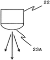
도 1에 나타낸 바와 같이, 실시 형태의 혈관 검지 장치(1)는 제1 조사부(2)와, 제2 조사부(3)와, 광 강도 검출부(4)와, 제어부(5)와, 통지부(6)를 가진다.As shown in FIG. 1 , the blood
제1 조사부(2)는 생체의 소정의 부위의 생체 외에서 생체 내를 향해, 소정의 조사 위치(21)에 광을 조사하기 위한 광원(22)을 가진다. 광원(22)은 조사하는 광의 파장을 조정할 수 있다. 도 2에 나타낸 바와 같이, 광원(22)은 광 강도 제어기(55)에 의해 조사 강도를 조정할 수 있다. 광원(22)은 파장 범위를 혈장의 무기물에 의해 광이 흡수되는 파장 범위 이외로 조정할 수 있다. 광원(22)은 혈액의 세포 성분에 의해 광이 흡수되는 파장 범위 이외로 조정할 수 있다. 여기서, 혈액의 세포 성분이란 혈중의 적혈구, 백혈구 및 혈소판이다. 혈장의 무기물이란 혈중의 물 및 전해질이다.The
실시 형태의 제1 조사부(2)는 후술하는 제어부(5)에 의한 유효 감쇠 계수(μeff)의 산출 방법에 따라, 광의 연속적인 조사나 광의 펄스 형상의 조사 등의 광을 조사하는 시간의 길이를 임의로 조정할 수 있다.The
제1 조사부(2)는 파장이 고정된 광원(22)을 이용할 수 있다. 제1 조사부(2)는 파장이 다른 복수의 광원 혹은 복수의 파장의 광을 혼합한 것일 수 있다. 제1 조사부(2)는, 예를 들면, 형광등, LED, 레이저, 백열등, HID, 할로겐 램프 등이다. 제1 조사부(2)의 조도는 광 강도 제어기(55)에 의해 제어되지만, 제어부(5)에 의해 제어될 수도 있다.The
실시 형태에서는, 광원(22)은 LED(Light Emitting Diode)이다. 도 3A, 도 3B에 나타낸 바와 같이, 광원(22)은 LED로부터의 조사광의 직선성을 높이기 위한 방향 조정부(23)를 가진다. 광원(22)에 LED를 그대로 이용한 경우에는 조사 시에 있어서의 확산이, 소위 외란 광과 마찬가지로, 측정값에 오차를 줄 가능성이 있다. 또한, 조사광이 생체 표면에서 확산하기 때문에, 피부 등의 정맥과 광원 사이에 존재하는 물질의 영향을 받게 된다.In the embodiment, the
도 3A에 나타낸 바와 같이, 실시 형태의 조사부(2)는 광원(22)의 LED의 발광면에, 방향 조정부(23)로서 렌즈(23A)를 구비한다. 이에 따라, 광원(22)의 LED에서 방출되는 확산 성분을 경감하고, 광의 직진성을 높인다.As shown in FIG. 3A, the
또한, 실시 형태에서는, 방향 조정부(23)에 렌즈(23A)가 구비되는 양태에 대하여 설명하였지만, 이에 한정되지 않고, 예를 들면, 조사부(2)는 방향 조정부(23)로서, 도 3B에 나타내는 핀홀(23B) 등을 구비함으로써 광의 직선성을 높여도 좋다.In addition, in embodiment, although the aspect with which the
실시 형태의 광원(22)은 서로 다른 제1 파장의 광 및 제2 파장의 광을 조사한다. 제1 파장의 광은 혈관 깊이를 검지하기 위한 블랭크 정보 및 혈류 정보를 검지하기 위한 광이다. 제2 파장의 광은 혈관까지의 조직 두께를 검지하기 위한 광이다.The
제1 파장의 광은 혈액이나 피부 혹은 근육 등의 영향이 적은 파장이 바람직하고, 일반적으로 생체의 창이라고 불리는 파장 영역, 즉 800nm±50nm(즉, 750nm 이상 850nm 이하)의 파장 영역의 광인 것이 바람직하다.The light of the first wavelength is preferably a wavelength with little influence from blood, skin, or muscle, and is generally light in a wavelength region called the window of the living body, that is, light in a wavelength region of 800 nm±50 nm (ie, 750 nm or more and 850 nm or less). do.
제2 파장의 광은 헤모글로빈이나 물 등의 흡수가 강해지는 파장이 바람직하다. 즉, 제2 파장의 광은 헤모글로빈을 타겟으로 하는 경우에는 500nm 이상 600nm 이하의 광인 것이 바람직하고, 물을 타겟으로 하는 경우에는 900nm 이상 1200nm 이하의 광인 것이 바람직하다.The light of the second wavelength is preferably a wavelength at which absorption of hemoglobin, water, or the like becomes strong. That is, the light of the second wavelength is preferably 500 nm or more and 600 nm or less light when hemoglobin is targeted, and is preferably 900 nm or more and 1200 nm or less light when water is targeted.
제2 조사부(3)는 생체의 소정의 부위의 생체 외에서 생체 내를 향해, 소정의 조사 위치(31)에 광을 조사하기 위한 광원(32)을 가진다. 광원(32)은 조사하는 광의 파장을 조정할 수 있다. 도 2에 나타낸 바와 같이, 광원(32)은 광 강도 제어기(55)에 의해 조사 강도를 조정할 수 있다. 광원(32)은 파장 범위를 혈장의 무기물에 의해 광이 흡수되는 파장 범위 이외로 조정할 수 있다. 광원(32)은 혈액의 세포 성분에 의해 광이 흡수되는 파장 범위 이외로 조정할 수 있다. 여기서, 혈액의 세포 성분이란 혈중의 적혈구, 백혈구 및 혈소판이다. 혈장의 무기물이란 혈중의 물 및 전해질이다.The
제2 조사부(3)는 광 강도 검출부(4)에 대하여, 제1 조사부(2)의 반대측에 위치하는 것이 좋다. 이에 따라, 제1 조사부(2)와 제2 조사부(3)의 2 방향에서 광을 생체를 향해 조사하게 된다.The
광 강도 검출부(4)는 복수의 광 강도 검출부(4: 41, 42, 45, 46)를 포함하며, 어느 정도의 길이가 있다. 한 방향에서의 광의 조사만의 경우에는 배치에 관하여 광조사 측에 가까운 광 강도 검출부(4)의 정보만을 정확하게 검출하는 경우가 있다. 광 강도 검출부(4)의 양측이 혈관에 대하여 정확하게 배치되어 있음을 확인하기 위해서는 2 방향에서의 광의 응답을 보는 것이 바람직하다.The
제2 조사부(3)는 후술하는 제어부(5)에 의한 유효 감쇠 계수(μeff)의 산출 방법에 따라, 광의 연속적인 조사나 광의 펄스 형상의 조사 등의 광을 조사하는 시간의 길이를 임의로 조정할 수 있다.The
제2 조사부(3)는 파장이 고정된 광원(32)을 이용할 수 있다. 제2 조사부(3)는 파장이 다른 복수의 광원 혹은 복수의 파장의 광을 혼합한 것일 수 있다. 제2 조사부(3)는, 예를 들면, 형광등, LED, 레이저, 백열등, HID, 할로겐 램프 등이다. 제2 조사부(3)의 조도는 광 강도 제어기(55)에 의해 제어되지만, 제어부(5)에 의해 제어될 수도 있다.The
실시 형태에서는, 광원(32)은 LED(Light Emitting Diode)이다. 광원(22)과 마찬가지로, 광원(32)은 LED로부터의 조사광의 직선성을 높이기 위한 방향 조정부(33)를 가진다(미도시). 광원(32)에 LED를 그대로 이용한 경우에는 조사 시에 있어서의 확산이, 소위 외란 광과 마찬가지로, 측정값에 오차를 줄 가능성이 있다. 또한, 조사광이 생체 표면에서 확산하기 때문에, 피부 등의 정맥과 광원 사이에 존재하는 물질의 영향을 받게 된다.In the embodiment, the
제1 조사부(2)와 마찬가지로, 실시 형태의 제2 조사부(3)는 발광면에, 방향 조정부로서 렌즈를 구비하여도 되고, 핀홀 등을 구비할 수 있다.Like the
실시 형태의 광원(32)은 제3 파장의 광을 조사한다. 제3 파장의 광은 혈관 깊이를 검지하기 위한 블랭크 정보 및 혈류 정보를 검지하기 위한 광이다.The
제3 파장의 광은 혈액이나 피부 혹은 근육 등의 영향이 적은 파장이 바람직하고, 일반적으로 헤모글로빈의 흡수를 가지지 않는 파장(650nm 이상)이 바람직하다. 또한, 제3 파장의 광은 물을 흡수하지 않는 파장(900nm 이하)인 것이 바람직하다.The light of the third wavelength is preferably a wavelength having little effect on blood, skin, muscle, etc., and generally has a wavelength (650 nm or more) that does not absorb hemoglobin. In addition, it is preferable that the light of a 3rd wavelength is a wavelength (900 nm or less) which does not absorb water.
광 강도 검출부(4)는 생체에서 생체 외로 방출되는 광을 수광하여, 그 광 강도를 검출한다. 복수의 광 강도 검출부(4: 41, 42, 45, 46)를 이용하는 경우에는 광 강도 검출부(4: 41, 42)는 조사 위치(21)에서 각각 다른 거리에 설치된다. 도 1에 나타낸 바와 같이, 실시 형태에서는, 조사 위치(21)에서 소정의 간격으로 동일면 상에서 또한 직선 형상으로, 제1 광 강도 검출부(41) 및 제2 광 강도 검출부(42)가 순서대로 나열된다. 광 강도 검출부(4)는 포토 다이오드나 CCD나 CMOS일 수 있다.The light
또한, 광 강도 검출부(4: 45, 46)는 조사 위치(31)에서 각각 다른 거리에 설치된다. 실시 형태에서는, 조사 위치(31)는 조사 위치(21)에 대해, 광 강도 검출부(4)를 끼워 반대측에 설치된다. 조사 위치(31)에서 소정의 간격으로 동일 평면 상에서 또한 직선 형상으로, 제3 광 강도 검출부(46) 및 제4 광 강도 검출부(45)가 순서대로 나열된다.In addition, the light intensity detection units 4: 45 and 46 are provided at different distances from the
광 강도 검출부(4)에서 수광한 광은 광전류로 변환되고, 이 광전류는 광 강도 증폭부(56)에서 증폭되고, CPU(51)로 처리된다.The light received by the light
도 1에 나타낸 바와 같이, 실시 형태에서는, 조사 위치(21)에서 제1 광 강도 검출부(41)에 의한 제1 검출 위치(441)까지의 거리를 제1의 조사 검출간 거리(ρ1)로 하고, 조사 위치(21)에서 제2 광 강도 검출부(42)에 의한 제2 검출 위치(442)까지의 거리를 제2의 조사 검출간 거리(ρ2)로 한다.As shown in Fig. 1, in the embodiment, the distance from the
또한, 도 1에 나타낸 바와 같이, 조사 위치(31)에서 가장 가까운 검출 위치(446)까지의 거리를 제3 검출 거리(ρ6)로 하고, 조사 위치(31)에서 2번째로 가까운 검출 위치(445)까지의 거리를 제4 검출 거리(ρ5)로 한다.In addition, as shown in FIG. 1, let the distance from the
도 4에 나타낸 바와 같이, 광을 생체에 조사하는 조사 위치(21)와, 생체 중의 혈액(도면 중의 E)에서 방출되는 광 강도를 검출하는 검출 위치(44) 사이에 소정의 거리(ρ)를 설치한다. 소정의 거리(ρ)를 설치함으로써, 조사한 광(도면 중의 A)이 생체 표면 및 표면 근방의 산란체에 의해 반사되어 직접적으로 생체에서 방출되는 광(도면 중의 B)의 영향을 억제한다. 조사한 광이 혈액이 존재하는 깊이에 도달한 후, 혈액 중의 지질(도면 중의 D)에 의해 광이 반사된다.As shown in Fig. 4, a predetermined distance ρ between the
도 4는 도 1에 나타낸 것과 같은 조사 위치(31)에 관해서도 성립된다.Fig. 4 also holds for the
또한, 복수의 검출 위치(441, 442, 445, 446) 등을 설치하는 경우의 배열은 조사 위치(21, 31)에서 각각 다른 거리에 배치된다면 직선 형상으로 한정되는 것이 아니고, 원 형상, 파 형상, 지그재그 형상 등, 적절히 선택할 수 있다. 또한, 조사 위치(21, 31)에서 검출 위치(441, 442, 445, 446) 등까지의 제1 조사 검출간 거리(ρ1)나 제2 조사 검출간 거리(ρ2)나 제3 조사 검출간 거리(ρ6)나 제4 조사 검출간 거리(ρ5), 검출 위치(441, 442)간, 검출 위치(445, 446)간의 간격은 일정한 간격으로 한정되는 것이 아니며, 연속적일 수도 있다.In addition, the arrangement in the case of providing a plurality of
다음에, 혈관 검지 장치(1)의 제어계의 구성에 대하여 설명한다. 도 2는 실시 형태의 혈관 검지 장치(1)의 블럭도이다. 시스템 버스(52)를 통해, CPU(Central Processing Unit:51), ROM(Read Only Memory:53), RAM(Random Access Memory:54), 광 강도 제어기(55), 광 강도 증폭부(56), 기억부(57), 외부 I/F(Interface:58), 제1 조사부(2), 제2 조사부(3), 광 강도 검출부(4), 및 통지부(6)가 접속된다. CPU(51)와 ROM(53)과 RAM(54)과 광 강도 제어기(55)와 광 강도 증폭부(56)로 제어부(콘트롤러: 5)를 구성한다.Next, the configuration of the control system of the blood
ROM(53)은 CPU(51)에 의해 실행되는 프로그램이나 역치 값을 미리 기억한다.The
RAM(54)은 CPU(51)가 실행하는 프로그램을 전개하는 에리어와, 프로그램에 의한 데이터 처리의 작업 영역이 되는 워크 에리어 등의 다양한 메모리 에리어 등을 가진다.The
광 강도 제어기(55)는 제1 조사부(2) 및 제2 조사부(3)에서 조사하는 광의 조사 강도를 조정한다.The
광 강도 증폭부(56)는 검출 위치(441, 442, 445, 446)의 광 강도 검출부(4: 41, 42, 45, 46)에서 수광했을 때에 발생하는 광전류를 증폭하는 증폭 회로를 가진다.The light
기억부(57)는 검지·산출된 광 강도 등이나 유효 감쇠 계수(μeff) 등의 데이터를 기억한다. 기억부(57)는 HDD(Hard Disk Drive)나, 플래시 메모리나, SSD(Solid State Drive) 등의 비휘발성으로 기억하는 내부 메모리일 수 있다.The
외부 I/F(58)는, 예를 들면 클라이언트 단말(PC) 등의 외부 장치와 통신하기 위한 인터페이스이다. 외부 I/F(58)는 외부 장치와 데이터 통신을 하는 인터페이스일 수 있고, 예를 들면, 외부 장치에 로컬로 접속하는 기기(USB 메모리 등)일 수도 있고, 네트워크를 통해 통신하기 위한 네트워크 인터페이스일 수도 있다.The external I/
제어부(5)는 광 검출 강도부(4: 41, 42, 45, 46)에 의해 검출된 광 강도에 근거해 생체 내에 있어서의 혈관 배치 정보(예를 들면, 혈관 깊이 정보나 혈관 각도 정보)를 산출한다. 혈관 배치 정보는 소정의 파장의 조사광에 있어서의 광 강도 검출부(4)의 검출 강도에 근거해 산출된다. 실시 형태에서는, 혈관 배치 정보는 광원(22)의 조사광의 파장이 제1 파장 및 제2 파장, 및 광원(32)의 조사광 파장이 제3 파장에 있어서의 광 강도 검출부(4)의 검출 강도에 근거해 산출된다.The
광 강도 검출부(4)에서 얻을 수 있는 광 강도는 광 강도 검출부에서 검출된 제1 파장 및 제2 파장 및 제3 파장의 조사에 대응한 각각의 검출된 광 강도(I1λ, I2λ,…, Inλ)이다. 여기서, λ는 조사광의 파장이며, n는 광 강도 검출부(4)의 수이다. 본 실시 형태에서는 n는 4이다.The light intensity obtainable by the light
또한, 광 검출 강도부(4)에서 얻을 수 있는 광 강도는 흡수와 산란의 정보가 혼재한 유효 감쇠 계수(μeff)이다.In addition, the light intensity obtained by the light
실시 형태에 있어서의 제어부(5)는 광 강도비 또는 광 강도차를 산출한다.The
제어부(5)는 광 강도 검출부(4)에 의해 검출되고, 광 강도 증폭부(56)에서 증폭된 복수 위치의 광 강도의 대수를 취하여 유효 감쇠 계수(μeff)를 산출한다. 제어부(5)는 조사한 광이 검출 위치(44)까지의 거리를 멀게 함에 따라 수광 강도가 감쇠되어 가는 현상에 근거해 유효 감쇠 계수(μeff)를 산출한다.The
제1 조사부(2), 또는, 제2 조사부(3)에서 연속광을 조사하고, 제어부(5)는 광 강도 검출 위치(44)에서 검출된 광 강도에 기반하여, 광 조사부와 광 강도 검출부 사이의 거리(ρ)(제1~제4 조사 검출간 거리)와, ρ의 제곱과 광 강도(R(ρ))의 곱에서 유효 감쇠 계수(μeff)를 산출한다(수학식 1).Continuous light is irradiated from the

유효 감쇠 계수(μeff)는 광 조사부와 광 강도 검출부 사이의 거리(ρ)(제1~제4 조사 검출간 거리)나 조사광의 파장(제1~제3 파장)에 의존한다. 또한, 제어부(5)에 의한 유효 감쇠 계수(μeff)의 산출 방법은 상기의 산출법에 의한 것에 한정되지 않는다.The effective attenuation coefficient μeff depends on the distance ρ between the light irradiation unit and the light intensity detection unit (distance between first to fourth irradiation detection) or the wavelength of the irradiation light (first to third wavelengths). In addition, the calculation method of the effective attenuation coefficient mueff by the
유효 감쇠 계수(μeff)는 수학식 2에 나타낸 바와 같이, 흡수 계수(μa)도 포함한다.The effective attenuation coefficient [mu]eff also includes the absorption coefficient [mu]a, as shown in Equation (2).

헤모글로빈의 흡수가 큰 제2 파장을 이용했을 때에는 상대적으로 흡수 계수(μa)가 커지기 때문에, 유효 감쇠 계수(μeff)는 헤모글로빈의 흡수에 의존한다.When the second wavelength having a large absorption of hemoglobin is used, the absorption coefficient μa is relatively large, so the effective attenuation coefficient μeff depends on the absorption of hemoglobin.
계측 대상이 되는 혈액은 피부 조직 등과 달리, 혈관 내를 유동하고 있다. 이 혈류에 의해 얻을 수 있는 동적 파라미터를 혈류 정보로 정의한다. 실시 형태에서는, 분석에 있어서 일정 시간 계측함으로써, 혈류 정보를 산출하고, 혈관 위치를 판정한다.Blood to be measured flows through blood vessels, unlike skin tissues and the like. A dynamic parameter obtainable by this blood flow is defined as blood flow information. In the embodiment, blood flow information is calculated by measuring for a certain period of time in the analysis, and the blood vessel position is determined.
혈류 정보는 생체 내 물질에 대한 흡수가 작은, 혹은, 거의 없는 파장(제1 파장 또는 제3 파장)를 사용하여 얻어진 정보이다. 이것은, 운동에 의한 근육의 수축이나, 혈류량의 변동의 영향을 억제하고, 혈액의 유무를 정성적으로 판단하는 것을 목적으로 하고 있다.The blood flow information is information obtained by using a wavelength (first wavelength or third wavelength) having little or no absorption for a substance in a living body. This is aimed at suppressing the influence of muscle contraction and fluctuations in blood flow due to exercise, and qualitatively judging the presence or absence of blood.
제어부(5)는 표준 편차나, 브라운 운동이나, 자기 상관 함수나, 주파수 해석이나, 스페클이나, 도플러 시프트나, 레이놀즈 수나, 혈류량이나, 혈액량이나, 맥동 폭 등을 이용하여 분석하고, 혈액의 움직임을 계측하는 지표인 혈류 정보를 산출한다. 제어부(5)는 광 강도의 계측 시간을 20sec 이하로 하고, 이 계측 시간 내에 있어서의 광 강도의 시간 변동에서 혈류 정보를 산출할 수 있다.The
종전에는, 계측 대상 부위를 계측함에 있어, 시간에 의한 계측값의 변동량에는 주목하지 않고, 평균화시킨 값을 채용하고 있었다. 그렇지만, 혈액 계측에 있어서 정맥 등의 혈액이 풍부한 부위나 밀집하고 있는 부위를 계측한 편이, 혈액 정보가 많이 포함되기 때문에, 노이즈 요인이 적어진다. 비침습 계측에 있어서, 입사한 광이 정맥을 투과했는지 여부를 판단하려면 혈류에 의해 얻을 수 있는 정보를 취득하는 것이 바람직하다.In the past, in measuring the measurement target site, the averaged value was employed without paying attention to the amount of variation in the measured value with time. However, in blood measurement, when blood-rich sites such as veins or areas where blood is concentrated are measured, since blood information is included more, noise factors are reduced. In non-invasive measurement, in order to determine whether incident light has passed through a vein, it is desirable to acquire information obtainable by blood flow.
예를 들면 맥박 계측 등에서는 심박에 의한 주기성을 계측하기 위해, 동맥이 바람직하다고 여겨진다. 그렇지만, 정맥을 계측 대상으로 하는 실시 형태의 경우, 상기와 같은 주기성은 확인되지 않는다. 그 때문에, 최적 계측 부위의 위치 결정은 일정 시간 내에 있어서의, 혈류에 의한 수광 강도의 시간 변화의 불균형을 계측하는 것이 바람직하다.For example, in pulse measurement and the like, it is considered that an artery is preferable in order to measure the periodicity by the heartbeat. However, in the case of the embodiment in which veins are the measurement object, the periodicity as described above is not confirmed. Therefore, in determining the position of the optimal measurement site, it is preferable to measure the imbalance in the temporal change in light reception intensity due to blood flow within a certain period of time.
즉, 박동의 주기(0.5~2.0Hz 정도)가 관측되는 경우는 혈액의 존재가 확인되나, 정맥 이외의 정보도 많이 포함된다고 판단할 수 있다. 한편, 박동의 주기를 볼 수 없고, 주기성이 없는 혈류 정보가 정맥의 위치를 나타내는(적어도 정맥 정보에 의존하고 있다) 정보가 되고, 본 발명의 지질 계측에 적합한 생체의 부위라고 할 수 있다.That is, when the pulse cycle (about 0.5 to 2.0 Hz) is observed, the presence of blood is confirmed, but it can be determined that a lot of information other than veins is also included. On the other hand, since the cycle of the beating cannot be seen, the blood flow information without periodicity becomes information indicating the position of the vein (at least it depends on the vein information), and it can be said that it is a part of a living body suitable for the lipid measurement of the present invention.
또한, 상기 정보를 구별하기 위해서는 광 강도 검출부의 샘플링 레이트는 10msec 이하가 바람직하고, 분해능은 16bit 이상이 바람직하다.In addition, in order to distinguish the information, the sampling rate of the light intensity detection unit is preferably 10 msec or less, and the resolution is preferably 16 bits or more.
혈류 정보는 광 강도 검출부(4)에서 검출된 광 강도(I)의 시간 변동의 크기를 나타낸 변동 계수(CV), 및 유효 감쇠 계수(μeff)의 시간 변동의 크기를 나타낸 변동 계수(CV)를 포함한다.The blood flow information includes a coefficient of variation (CV) indicating the magnitude of the temporal variation of the light intensity (I) detected by the light
제어부(5)는 산출된 광 강도의 시간 변화(시간 변동)에서, 광 강도의 변동 계수(CV)를 산출한다. 변동 계수(CV)에 대해서는, 예를 들면, 이하의 수학식 3에 의해 산출할 수 있다.The
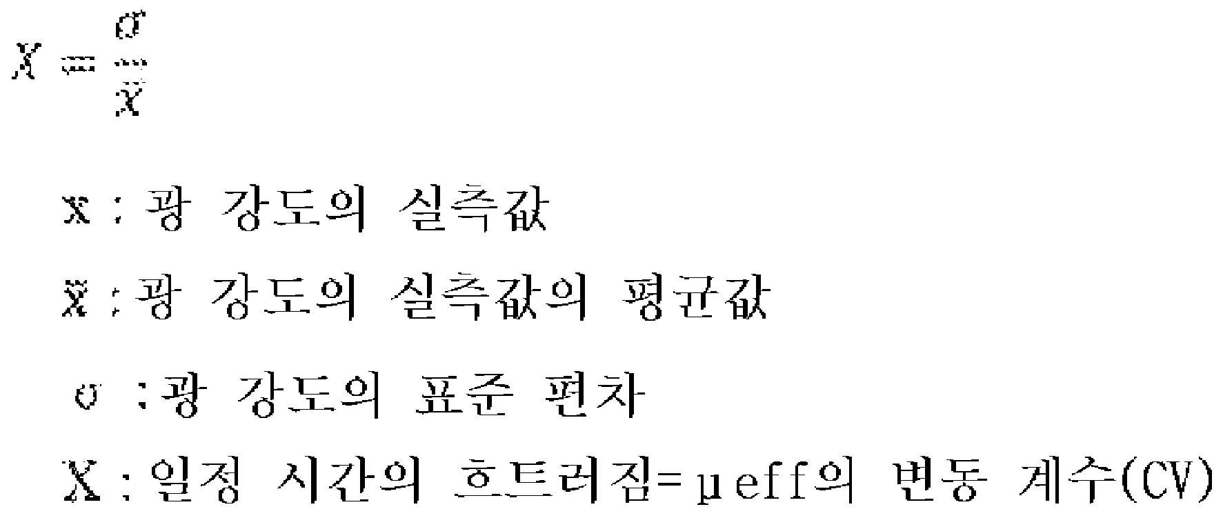
광 강도의 표준 편차는 이하의 수학식 4로 구해진다.The standard deviation of the light intensity is obtained by the following equation (4).

여기서, < >는 평균을 나타낸다.Here, < > represents the average.
변동 계수(CV)를 산출하기 위해 광 강도를 계측하는 시간을 1msec 이상 30sec 이하, 바람직하게는, 5msec 이상 25sec 이하, 더욱 바람직하게는 10msec 이상 20sec 이하로 하는 것이 좋다(또한, "sec"는 "초"의 약어이다).In order to calculate the coefficient of variation (CV), the time for measuring the light intensity is preferably set to 1 msec or more and 30 sec or less, preferably 5 msec or more and 25 sec or less, more preferably 10 msec or more and 20 sec or less (in addition, "sec" means " seconds").
제어부(5)는 제1 조사부(2)의 제1 파장의 조사광에 의한 유효 감쇠 계수(μeff) 또는 흡수 계수(μa)에서 혈관 깊이 정보를 산출한다(후술하는 연산식 1). 또한, 제어부(5)는 제1 조사부(2)의 제1 파장 및 제2 파장의 조사광에 의한 유효 감쇠 계수(μeff)와 흡수 계수(μa)에서 혈관 깊이 정보를 산출한다(후술하는 연산식 2).The
제어부(5)는 제2 조사부(3)의 제3 파장의 조사광에 의한 광 강도(I)에서 혈관 각도 정보를 산출한다(후술하는 연산식 3). 또한, 제어부(5)는 제1 조사부(2)의 제1 파장의 조사광에 의한 유효 감쇠 계수(μeff)의 변동 계수(CV), 및 제2 조사부(3)의 제3 파장의 조사광에 의한 광 강도(I)의 변동 계수(CV)에서 혈관 각도 정보를 산출한다(후술하는 연산식 4).The
그리고, 제어부(5)는 혈관 깊이 정보와 혈관 각도 정보에서 혈관 배치를 판정한다.Then, the
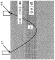
실시 형태는, 혈관 깊이 정보를 탐색하는 장치·방법을 제공한다. 도 5에 나타낸 바와 같이, 광 조사 위치(21)와 광 검출 위치(44)까지의 평균적으로 광이 지나는 광로를 r로 한다. 또한, 표피·진피층의 두께를 d1, 혈관층의 두께(즉, 혈관의 굵기)를 d2로 한다.An embodiment provides an apparatus/method for searching blood vessel depth information. As shown in Fig. 5, the optical path through which light passes on average from the
산란 정보는 표피·진피층 및 혈관층에서 얻을 수 있다. 혈류 정보는 혈관층에서만 얻을 수 있다.Scattering data can be obtained from the epidermis, dermis, and vascular layers. Blood flow information can only be obtained from the blood vessel layer.
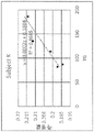
도 6은 사람 전완부의 정맥 바로 위에서의 측정을 거리(0)로 했을 때, 평행 어긋남 거리를 가로축으로, 혈류 정보로서 파장 810nm의 유효 감쇠 계수(μeff)의 변동 계수(CV)를 세로축으로 플롯한 것이다. 도 6에 나타낸 바와 같이, 변동 계수(CV)는 혈관의 바로 위에서 최대(도면 중의 0.0012 미만, 즉, 1.2% 미만)가 되는 경향이 있다.6 is a plot of the coefficient of variation (CV) of the effective attenuation coefficient (μeff) at a wavelength of 810 nm as blood flow information on the vertical axis, with the parallel displacement distance as the distance (0) when measured directly above the vein of the human forearm. will be. As shown in FIG. 6 , the coefficient of variation (CV) tends to be maximum (less than 0.0012 in the figure, ie, less than 1.2%) just above the vessel.
제어부(5)는 혈류 정보로서 제1 파장의 유효 감쇠 계수(μeff)의 변동 계수(CV)가 너무 작은 경우에 측정 오류로서 검지한다.The
측정 오류로서 인정되는 범위는 변동 계수(CV)가 0.5% 이하이다.The range recognized as a measurement error has a coefficient of variation (CV) of 0.5% or less.
표피·진피층과 혈관층에 대한 광의 거동은 파장마다 다르다. 예를 들면, 제2 파장의 광은 혈관층을 통과했을 때에 매우 많은 흡수의 영향을 받는다. 제1 파장의 광은 표피·진피층과 혈관층에서 흡수의 영향은 변하지 않지만, 그 흡수의 영향의 대부분은 물의 흡수이다. 810nm의 광은 표피·진피층에서의 흡수가 거의 없다. 그러한 특성의 차이에서 깊이 정보를 산출한다.The behavior of light on the epidermis, dermis, and blood vessel layers is different for each wavelength. For example, when light of the second wavelength passes through the blood vessel layer, it is affected by a very large amount of absorption. In the light of the first wavelength, the effect of absorption in the epidermis/dermis layer and the vascular layer does not change, but most of the effect of the absorption is water absorption. There is almost no absorption of light at 810 nm in the epidermis and dermis. Depth information is calculated from the difference in such characteristics.
유효 감쇠 계수(μeff)는 제1 광 강도 검출부(41) 및 제2 광 강도 검출부(42)가 검출한 광 강도에서 상기의 수학식 1에 의해 구할 수 있다.The effective attenuation coefficient μeff can be obtained from the light intensity detected by the first light
제어부(5)는 혈관 깊이 정보를 제1 조사부(2)의 제1 파장(810nm) 및 제2 파장(970nm)의 조사광에 의해 얻어진 광 강도에서 얻어진 유효 감쇠 계수에 의해, 하기 수학식 5의 연산식 1에 의해 산출한다. 계산 결과를 도 7A에 나타낸다.The
하기 수학식 5의 연산식 1에 의한 혈관 깊이 정보의 산출의 실증을 위해, 고체 모의 생체(고체 팬텀)의 표면에서 깊이 일정한 조건으로 중공 형상의 구멍을 뚫은 혈관 팬텀을 이용하여 실험을 수행하였다. 도 7A에, 하기 수학식 5의 연산식 1에 의한 혈관 깊이 정보와 혈관 팬텀의 혈관 구멍의 깊이(혈관 깊이)의 관계를 나타내었다.In order to demonstrate the calculation of blood vessel depth information by
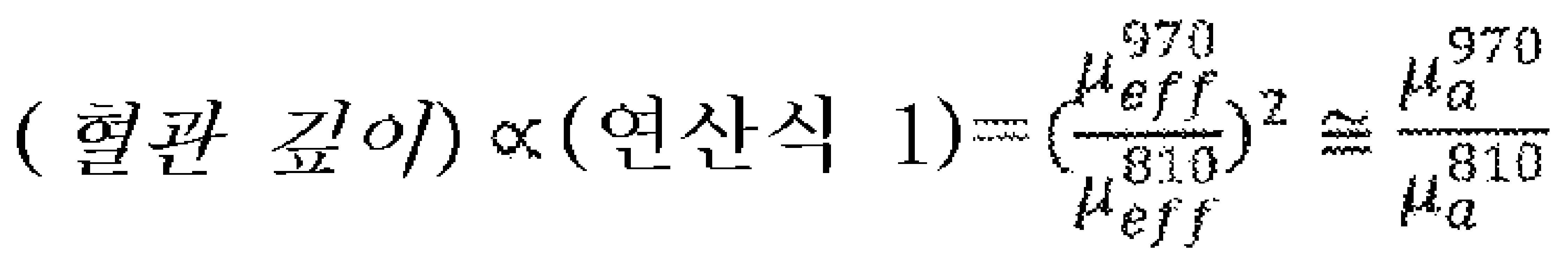
수학식 5에서, 혈관 깊이는 연산식 1에 의한 혈관 깊이 정보에 비례하고, μeff는 유효 감쇠 계수인 것을 나타내고, 우상 첨자(810, 970)는 파장(nm)을 나타낸다(즉, 수학식 1에서 조사광의 파장 970nm와 810nm의 경우에 얻어진 유효 감쇠 계수인 것을 나타낸다). 또한, μa는 흡수 계수인 것을 나타내고, 우상 첨자(810, 970)는 파장(nm)을 나타낸다(즉, 수학식 1과 수학식 2에서 조사광의 파장 970nm와 810nm의 경우에 얻어진 흡수 계수인 것을 나타낸다). 810nm는 제1 조사부(2)의 제1 파장이며, 970nm는 제1 조사부(2)의 제2 파장이다.In
도 7A에서, 수학식 5의 연산식 1에 의한 혈관 깊이 정보를 이용한 경우의 최적 범위는 본 발명자들이 실제로 지방 부하 시험을 수행하여, 그 생체 측정에서 얻어진 범위인 1.4<(연산식 1에 의한 혈관 깊이 정보)<2.0로 하는 것이 바람직하다. 연산식 1에 의한 혈관 깊이 정보를 이용한 경우의 최적 범위는 광 강도 또는 수광 거리에 따라 적정 범위를 변경하는 것이 보다 바람직하다.In FIG. 7A, the optimal range when using the blood vessel depth information according to
도 12A와 도 12B는 지질을 측정하고 있는 혈관의 측정 적성을 알아보기 위해, 지방 부하 시험을 실시하고, 가로축에 혈중 지질 농도, 세로축에 파장 810nm(제1 파장)를 이용하여 상기 특허 문헌 1(국제 공개 제2014/087825호 공보)에 기재된 수법에 기초하여 지질 농도와의 상관을 확인한 도면이다. 연산식 1에 의한 혈관 깊이 정보의 범위를 1.4<(연산식 1에 의한 혈관 깊이 정보)<2.0의 경우의 측정만을 성공 측정으로 하고, 그 이외의 측정을 오류로서 제외하면, 광학적 수법과 채혈 수법의 측정값의 상관을 나타내는 R2 곱값이 0.788(도 12B)로 좋아지고 있다.12A and 12B show that, in order to determine the measurement aptitude of blood vessels for measuring lipids, a fat load test is performed, the blood lipid concentration on the horizontal axis and the wavelength 810 nm (first wavelength) on the vertical axis are used in Patent Document 1 ( It is a figure which confirmed the correlation with a lipid concentration based on the method described in International Publication No. 2014/087825). If only the measurement in the case where the range of the blood vessel depth information according to
수학식 5의 연산식 1에 의한 혈관 깊이 정보에서 혈관 깊이(d1)를 이끄는 경우, 도 7A에 나타내는 하기의 비례 관계식(수학식 6)에서 혈관 깊이(d1)를 산출할 수 있다.When the blood vessel depth d1 is derived from the vessel depth information by
![]()
![]()
또한, 제어부(5)는 혈관 깊이 정보를 제1 조사부(2)의 제1 파장(810nm) 및 제2 파장(505nm)의 조사광에 의해 얻어진 광 강도에서 얻어진 유효 감쇠 계수에 의해, 하기 수학식 7의 연산식 2에 의해 산출한다.In addition, the
하기 수학식 7의 연산식 2에 의한 혈관 깊이 정보의 산출의 실증을 위해, 고체 모의 생체(고체 팬텀)의 표면에서 깊이 일정한 조건으로 중공 형상의 구멍을 뚫은 혈관 팬텀을 이용하여 실험을 수행하였다. 도 7B에, 하기 수학식 7의 연산식 2에 의한 혈관 깊이 정보와 혈관 팬텀의 혈관 구멍의 깊이(혈관 깊이)의 관계를 나타내었다.In order to demonstrate the calculation of blood vessel depth information by
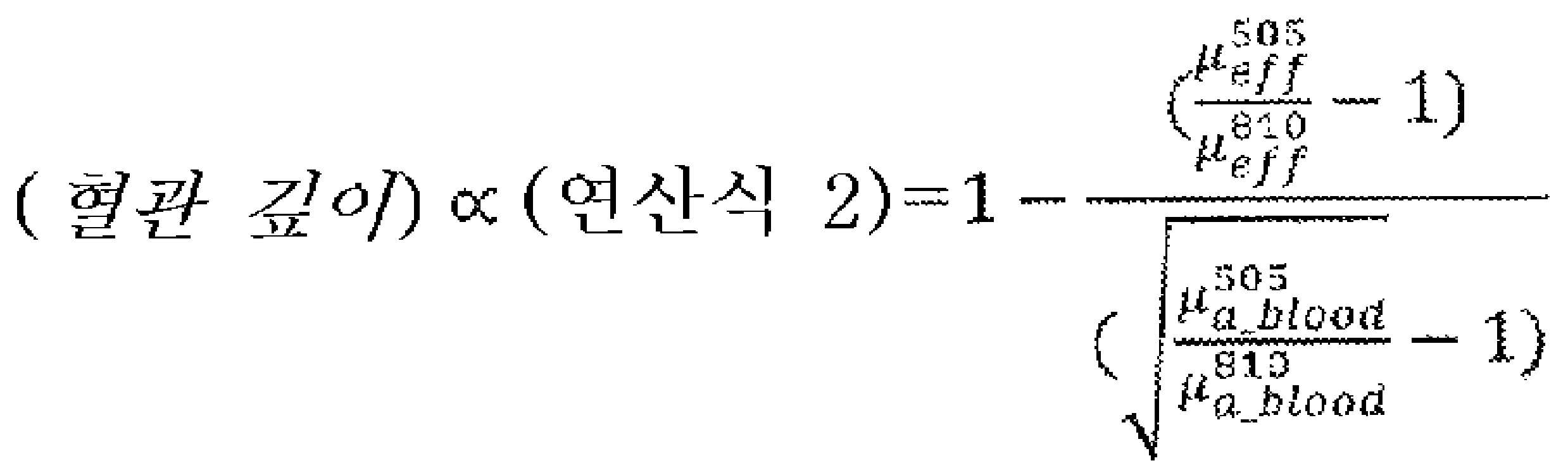
수학식 7에서, 혈관 깊이는 연산식 2에 의한 혈관 깊이 정보에 비례하고, 유효 감쇠 계수(μeff)의 우상 첨자(505, 810)는 상기 광 파장(nm)을 나타낸다(즉, 수학식 1에서 조사광의 파장 505nm와 810nm의 경우에 얻어진 유효 감쇠 계수인 것을 나타낸다). 수학식 7의 우변의 분수의 분모(μ)에 있어서의 우하 첨자는 혈액의 흡수인 것을 나타내고, 우상 첨자(505, 810)는 상기 광 파장(nm)을 나타낸다(즉, 수학식 1과 수학식 2에서 조사광의 파장 505nm와 810nm의 경우에 얻어진 흡수 계수인 것을 나타낸다). 505nm는 제1 조사부(2)의 제2 파장이다. 810nm는 제1 조사부(2)의 제1 파장이다.In Equation 7, the vessel depth is proportional to the vessel depth information by
수학식 7의 μ의 첨자는 혈액의 흡수를 나타내고, 분수는 제1 파장의 혈액의 흡수와 제2 파장의 혈액의 흡수의 비를 나타내고, 일반적으로 그 범위는 하기 수학식 8로 나타난다.The subscript of μ in Equation 7 represents the absorption of blood, and the fraction represents the ratio of the absorption of the blood of the first wavelength to the absorption of the blood of the second wavelength, and the range is generally expressed by Equation 8 below.

수학식 7의 연산식 2에 의한 혈관 깊이 정보에서 혈관 깊이(d1)를 이끄는 경우, 도 7B에서 하기의 비례 관계식(수학식 9)에서 산출할 수 있다.When the blood vessel depth d1 is derived from the vessel depth information by
![]()
![]()
도 7B에서는, 수학식 7의 분모는 4.48이다.In Fig. 7B, the denominator of Equation 7 is 4.48.
또한, 제어부(5)에 의한 혈관 깊이 정보의 산출 방법은 산란 정보(유효 감쇠 정보)의 연산에 의한 깊이 정보 산출법이며, 상기의 계산법에 의한 것에 한정되지 않는다.Note that the method for calculating the blood vessel depth information by the
즉, 수학식 5, 및 수학식 7의 모두 이용하여도, 지질 측정에 있어서 정확하게 지질을 반영하는 값을 얻을 수 있는 혈관 깊이의 범위 외의 값을 오류로서 검지함으로써, 일정 범위 내의 깊이의 혈관으로 혈관 깊이 정보를 산출하는 것이 가능해진다.That is, even by using both
제어부(5)는 변동 계수(CV)(혈류 정보)가 0.5% 이상이며, 또한, 수학식 5, 혹은, 수학식 7 등에 의해 나타나는 유효 감쇠 계수의 연산에 의한 혈관 깊이 정보가 혈관 팬텀을 이용한 실험 등에 의해, 미리 정해진 일정 범위 내(예를 들면 1.4보다 크고 2.0보다 작다)의 때에, 비침습 지질 계측에 있어서, 양호한 데이터가 취득할 수 있는 혈관의 깊이인 장소라고 판단한다.In the
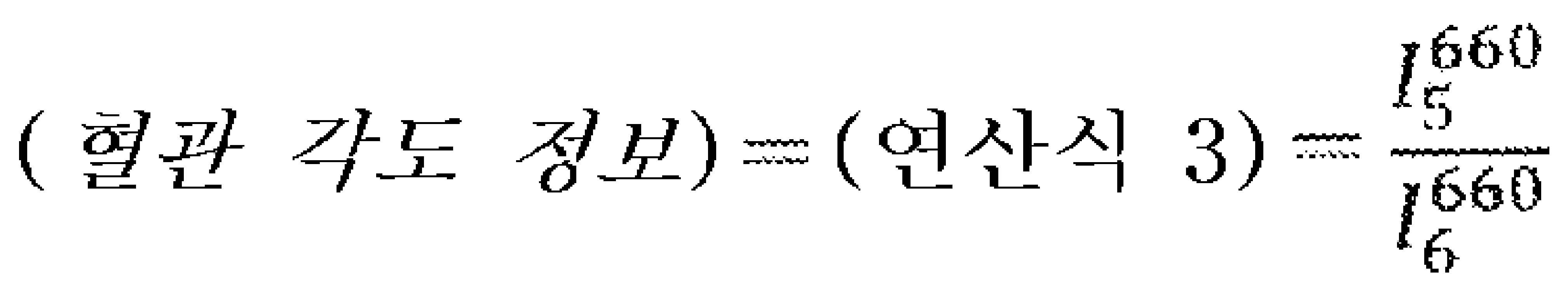
또한, 제어부(5)는 혈관 각도 정보를 제2 조사부(3)의 제3 파장(660nm)의 조사광에 의해 얻어진 광 강도에 의해, 하기 수학식 10의 연산식 3에 의해 산출한다. 제어부(5)는 상기 수학식 5의 연산식 1과 하기 수학식 10의 연산식 3이 동시에 있는 범위를 채우는 경우에, 혈관 검지 장치(1)의 광 검출 강도부(4: 41, 42, 45, 46)가 혈관 바로 위에 평행하게 배치되어 있는 것으로 판단한다.In addition, the
즉, 제어부(5)는 혈관 깊이 정보와 혈관 각도 정보에 기반하여, 수평 방향에 대하여 혈관 검지 장치(1)의 광 검출 강도부(4: 41, 42, 45, 46)의 배치 방향과 혈관의 방향이 평행하다고 판단한다.That is, the
수학식 5의 연산식 1에 의한 혈관 깊이 정보 및 하기 수학식 10의 연산식 3에 의한 혈관 각도 정보의 실증을 위해, 고체 모의 생체(고체 팬텀)의 표면에서 깊이 일정한 조건으로 중공 형상의 구멍을 뚫은 혈관 팬텀을 이용하여 실험을 수행하였다. 도 8A에, 하기 수학식 5의 연산식 1에 의한 혈관 깊이 정보와 혈관 팬텀의 혈관의 방향과 혈관 검지 장치(1)의 PD 배치 방향(광 검출 강도부(4: 41, 42, 45, 46)의 배치 방향)의 어긋남 각도의 관계를 나타내었다. 도 8B에, 하기 수학식 10의 연산식 2에 의한 혈관 각도 정보와 혈관 팬텀의 혈관의 방향과 혈관 검지 장치(1)의 PD 배치 방향(광 검출 강도부(4: 41, 42, 45, 46)의 배치 방향)의 어긋남 각도의 관계를 나타내었다.In order to demonstrate the blood vessel depth information according to
연산식 1의 값이 어느 범위 내에 들어간 경우에, 제1 조사부(2) 측이 혈관의 바로 위에 배치되어 있음을 나타낸다.When the value of
혈관 깊이 정보와 혈관 각도 정보의 일방 혹은 쌍방에서 일정한 범위 내를 채우면, 제어부(5)는 광 검출 강도부(4: 41, 42, 45, 46)의 배치 방향과 혈관의 방향의 관계가 평행하게 혈관 검지 장치(1)가 배치되었다고 판단한다.When one or both of the vessel depth information and the vessel angle information fill within a certain range, the
여기서 말하는 광 검출 강도부(4: 41, 42, 45, 46)의 배치 방향과 혈관의 방향의 관계에 있어서의 평행에는, 수평 방향 및 연직 방향이 있다.The parallel in the relationship between the arrangement direction of the light detection intensity sections 4: 41, 42, 45, and 46 and the direction of the blood vessel described herein includes a horizontal direction and a vertical direction.
도 9A는 혈관 검지 장치와 생체 내의 혈관의 관계를 상면에서 본 도면이며, 도 9B는 혈관 검지 장치와 생체 내의 혈관의 관계를 측면에서 본 도면이다. 도 9A에 나타낸 바와 같이, 광 검출 강도부(4: 41, 42, 45, 46)의 배치 방향과 혈관이 이루는 수평 방향으로 이루는 어긋남 각도(θh)가 존재한다. 어긋남 각도(θh)가 0인 경우에 수평 방향으로 평행하게 한다.Fig. 9A is a diagram showing the relationship between the blood vessel detecting device and blood vessels in the living body from the top, and Fig. 9B is a diagram showing the relationship between the blood vessel detecting device and blood vessels in the living body viewed from the side. As shown in Fig. 9A, there is a deviation angle θh between the arrangement direction of the light detection intensity units 4: 41, 42, 45, and 46 and the horizontal direction formed by the blood vessel. When the deviation angle θh is 0, it is made parallel to the horizontal direction.
도 9B에 나타낸 바와 같이, 광 검출 강도부(4: 41, 42, 45, 46)의 배치 방향과 혈관이 이루는 연직 방향으로 이루는 어긋남 각도(θv)가 존재한다. 어긋남 각도(θv)가 0인 경우에 연직 방향으로 평행하게 한다.As shown in Fig. 9B, there is a deviation angle θv between the arrangement direction of the light detection intensity portions 4: 41, 42, 45, and 46 and the vertical direction formed by the blood vessel. When the deviation angle θv is 0, it is made parallel in the vertical direction.
상기 연산식 3에 의해, 광 검출 강도부(4: 41, 42, 45, 46)의 배치 방향과 혈관의 방향이 평행인 것을 판별할 수 있다. 또한, 연산식 3만으로는 몰라도 상기 연산식 1도 포함하여 평행 여부를 판별할 수 있다. 이론으로서는 혈액이 있는 장소에서는 광 조사 위치로부터의 거리에 의한 감쇠가 크므로, 비를 취했을 때에 값이 작아지는 경향이 있다. 연산식 3이 너무 큰 경우, 제2 조사부 측이 혈관의 위에 배치되어 있지 않고, 연산식 1이 너무 작은 경우, 제1 조사부 측이 혈관의 위에 배치되어 있지 않게 되므로, 양쪽을 만족시키는 범위라면 혈관과 평행하게 배치되어 있게 된다. 연산식 3의 범위는 도 8B보다 팬텀의 실시예에 있어서는 0.47 이하이다.It can be discriminated that the arrangement direction of the light detection intensity units 4: 41 , 42 , 45 , and 46 is parallel to the direction of the blood vessel by the above equation (3). In addition, even if
제어부(5)는 상기 연산식 3의 값이, 혈관 팬텀을 이용한 실험 등에 의해, 미리 정해진 범위 내에 들어갔을 때에, 제2 조사부(3) 측의 광 검출 강도부(4: 45, 46)가 혈관의 바로 위에 배치되어 있는 것으로 판단한다.When the value of
제어부(5)는 상기 연산식 1 및 상기 연산식 3이 동시에 소정의 설정 범위에 들어가 있을 때에는, 광 검출 강도부(4: 41, 42, 45, 46)가 혈관의 바로 위에 배치되어 있는 것으로 판단한다.The
도 8A에서 수학식 5의 연산식 1에 의한 혈관 깊이 정보를 이용한 경우의 최적 범위는 고체 모의 생체를 이용한 경우, (연산식 1)>0.7로 하는 것이 바람직하다. 연산식 1에 의한 혈관 깊이 정보를 이용한 경우의 최적 범위는 광 강도 또는 수광 거리 또는 대상물에 따라 적정 범위를 변경하는 것이 보다 바람직하다.In FIG. 8A, it is preferable that the optimal range when using the blood vessel depth information by
도 8B에서 연산식 3에 의한 혈관 각도 정보를 이용한 경우의 최적 범위는 고체 모의 생체를 이용한 경우, (연산식 3)<0.41로 하는 것이 바람직하다. 연산식 2에 의한 혈관 깊이 정보를 이용한 경우의 최적 범위는 광 강도 또는 수광 거리 또는 대상물에 따라 적정 범위를 변경하는 것이 보다 바람직하다.In Fig. 8B, it is preferable that the optimal range when using the blood vessel angle information according to
제어부(5)는 혈관 각도 정보를 제1 조사부(2)의 제1 파장(810nm) 및 제2 파장(660nm)의 조사광에 의해 얻어진 광 강도에서 얻어진 유효 감쇠 계수의 변동 계수와, 제2 조사부(3)의 제3 파장(660nm)의 조사광에 의해 얻어진 광 강도의 변동 계수에서, 하기 수학식 11의 연산식 4에 의해 산출할 수 있다. 제어부(5)는 하기 연산식 4가 있는 수치 범위를 충족하는 측정 범위에 있어서, 혈관 깊이가 거의 일정하다고 판단한다.The
즉, 제어부(5)는 혈관 검지 장치(1)의 광 검출 강도부(4: 41, 42, 45, 46)가 연직 방향에 대하여 혈관과 평행하다고 판단한다.That is, the

수학식 11에서, 분자는 유효 감쇠 계수(μeff)의 변동 계수를 나타내고, 분모는 검출광 강도(I)의 변동 계수를 나타내고, 우상 첨자는 조사광의 파장을 나타낸다.In Equation 11, the numerator represents the coefficient of variation of the effective attenuation coefficient μeff, the denominator represents the variation coefficient of the detection light intensity I, and the upper right subscript represents the wavelength of the irradiation light.
수학식 11의 연산식 4에 의한 혈관 각도 정보를 이용한 경우의 최적 범위는 (연산식 4)>1.5로 하는 것이 바람직하다. 연산식 4에 의한 혈관 각도 정보를 이용한 경우의 최적 범위는 광 강도 또는 수광 거리 또는 대상물에 따라 적정 범위를 변경하는 것이 보다 바람직하다.It is preferable that the optimal range in the case of using the blood vessel angle information by
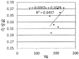
수학식 11의 연산식 4에 의한 혈관 각도 정보의 실증을 위해, 인간 지방 부하 시험에 있어서, 실시 형태의 혈관 검지 장치에 있어서의 오류 판정 기능의 검증을 수행하였다. 우선, 정맥 가시화 장치를 이용하여 정맥이라고 판단한 장소에서 측정하고, 혈중 지질(TG)과 측정값의 상관 관계를 도 10A(오류 배제 전)에 나타낸다. 또한, 수학식 5(연산식 1)가 일정 범위 외의 점을 제외한 경우의 상관 관계를 도 10B(오류 배제 후)에 나타낸다. 도 10A, 도 10B에 나타낸 바와 같이, 오류 판정점을 제외함으로써, 채혈에 의한 혈중 지질 농도와 광학 계측에 의한 측정 결과의 상관을 나타내는 R2 곱값이 약 0.35에서 약 0.655로 좋아지고 있다.In order to verify the blood vessel angle information by the calculation formula (4) in the formula (11), in the human fat load test, the error determination function of the blood vessel detection device of the embodiment was verified. First, measurement was performed at a location determined to be a vein using a vein visualization device, and the correlation between blood lipid (TG) and the measured value is shown in FIG. 10A (before error exclusion). In addition, the correlation in the case where Equation 5 (Equation 1) excludes points outside a certain range is shown in FIG. 10B (after error exclusion). As shown in FIGS. 10A and 10B , by excluding the error judgment point, the R2 product value indicating the correlation between the blood lipid concentration by blood sampling and the measurement result by optical measurement improves from about 0.35 to about 0.655.
실시 형태의 통지부(6)는 버저, 바이브레이터, 램프, 액정 화면 등이다. 제어부(5)가 혈관을 검지에 적합한 부위라고 판별한 경우에, 제어부(5)는 통지부(6)에 버저를 울리는, 진동시키는, 램프를 점등시키는, 또는 액정 화면에 표시한다. 이에 따라, 측정에 적합한 혈관 위치임을 사용자에게 통지한다.The
실시 형태의 통지부(6)는 제어부(5)가 최적 혈관 배치가 아니라고 판단한 경우에 오류로서 사용자에게 고지한다. 통지의 방법은 버저를 울리는, 진동시키는, 램프를 점등시키는, 또는 액정 화면에 표시한다. 이에 따라 측정이 오류임을 사용자에게 통지한다.The
이상과 같은 구성을 구비하는 실시 형태의 혈관 검지 장치(1)에 있어서, 미리 설정되어 있는 프로그램에 기반하여, 혈관 검지 장치(1)는 혈관 검지 처리를 실행한다. 도 11은 실시 형태의 혈관 검지 처리의 흐름도이다.In the blood
제1 조사부(2) 또는 제2 조사부(3)가 조사광의 직선성을 높이기 위한 방향 조정부를 가지는 차광판을 통해, 조사 위치(21)에 연속광을 조사한다(S 101).The
제1 광 강도 검출부(41)가 제1의 검출 위치(441)에 있어서의 광 강도를 검출함과 동시에, 제2 광 강도 검출부(42)가 제2 검출 위치(442)의 광 강도를 검출한다. 제2 조사부(3)의 광에 대해서는 광 강도 검출부(46)가 제3 검출 위치(446)에 있어서의 광 강도를 검출함과 동시에, 광 강도 검출부(45)가 제4 검출 위치(445)의 광 강도를 검출한다(S 102).The first light
제어부(5)는 광 검출 강도 검출부(4)에 의해 검출된 광 강도에 근거해 생체 내에 있어서의 유효 감쇠 계수(μeff)나 변동 계수(CV) 등의 혈류 정보를 산출한다(S 103).The
예를 들면, 제어부(5)는 광 강도 검출부(4)에 의해 검출된 복수 위치의 광 강도의 대수를 취하여 유효 감쇠 계수(μeff)를 산출한다. 제어부(5)는 조사한 광이 검출 위치(44)까지의 거리를 멀게 함에 따라 산란에 의해 감쇠되어 가는 현상에 근거해 유효 감쇠 계수(μeff)를 산출한다.For example, the
제어부(5)는 광 강도(I)나 유효 감쇠 계수(μeff)나 변동 계수(CV) 등의 혈류 정보에 기반하여, 예를 들면, 수학식 5 및 수학식 7 및 수학식 10 및 수학식 11(즉, 연산식 1에서 4) 등에 의해 나타나는 혈관 깊이 정보와 혈관 각도 정보 등의 혈관 배치 정보를 산출한다(S 104). 또한, 수학식 5, 수학식 7, 수학식 10, 수학식 11의 내용, 및 혈관 깊이 정보와 혈관 각도 정보의 산출법에 대해서는 상기하였다.The
제어부(5)는 혈관 깊이 정보 및 혈관 각도 정보가 혈관 팬텀을 이용한 실험 등에 의해, 미리 정해진 일정 범위 내의 경우에 최적 혈관 위치라고 판별한다(S 105). 또한, 제어부(5)는 일정 범위 외의 경우에는 측정 오류라고 판정한다.The
제어부(5)는 최적 혈관 배치라고 판별한 경우에, 통지부(6)에 램프를 점등시키는, 또는 액정 화면에 표시하는 통지 제어를 수행한다. 혹은 오류라고 판별한 경우에 마찬가지의 제어를 수행한다(S 106).When it is determined that the optimal blood vessel arrangement is the optimal blood vessel arrangement, the
이상 설명한 것처럼, 본 실시 형태의 혈관 검지 장치 및 그 방법에 의하면, 검출광 강도 및 혈류 정보에 기반하여, 혈관의 배치가 혈관 중의 성분의 측정에 적합한지 여부를 판정하는 것이 가능해진다.As described above, according to the blood vessel detecting device and method of the present embodiment, it is possible to determine whether the arrangement of blood vessels is suitable for measurement of components in the blood vessels based on the detected light intensity and blood flow information.
또한, 실시 형태의 혈관 검지 방법을 이용한 오류 판정법은 제어부에 의해 얻어진 수광 강도에 의한 연산 결과에서, 그 위치가 측정에 부적당한 경우에 그것을 통지부에 의해 고지한다.Further, in the error determination method using the blood vessel detection method of the embodiment, when the position is unsuitable for measurement in the calculation result based on the received light intensity obtained by the control unit, it is notified by the notification unit.
다시 말하면 측정 위치가 혈액의 측정에 적합한지 여부를 판단 가능하게 된다.In other words, it is possible to determine whether the measurement position is suitable for blood measurement.
또한, 실시 형태의 혈관 검지 장치 및 방법에 의하면, 측정 중에 측정값이 어긋난 경우에 그 측정을 무효한 측정으로 하고, 제외하는 것이 가능해진다. 만일 최적 계측 부위에서 측정할 수 없었던 경우에 있어서도 데이터의 신뢰성에 의문을 제기함으로써 그 측정을 제외할 수 있다.In addition, according to the blood vessel detecting device and method of the embodiment, when a measured value deviates during a measurement, the measurement can be set as invalid and excluded. Even if measurements cannot be made at the optimal measurement site, the measurement can be excluded by questioning the reliability of the data.
[실시예][Example]
이하에, 본 발명의 실시예에 대하여 설명하지만, 본 발명은 하기의 실시예에 한정되지 않는다.Examples of the present invention will be described below, but the present invention is not limited to the following examples.
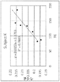
인간 지방 부하 시험에 있어서, 본 실시예의 혈관 검지 장치에 있어서의 오류 판정 기능의 검증을 수행하였다. 우선, 정맥 가시화 장치를 이용하여 정맥이라고 판단한 장소에서 측정하고, 혈중 지질(TG)과 측정값의 상관 관계를 도 12A(오류 배제 전)에 나타낸다. 또한, 수학식 5가 일정 범위 외의 점을 제외한 경우의 상관 관계를 도 12B(오류 배제 후)에 나타낸다. 도 12A, 도 12B에 나타낸 바와 같이, 오류 판정점을 제외함으로써, 채혈에 의한 혈중 지질 농도와 광학 계측에 의한 측정 결과의 상관을 나타내는 R2 곱값이 0.788에서 0.869로 좋아지고 있다.In the human fat load test, the error determination function of the blood vessel detection device of this example was verified. First, measurements were made at a location determined to be veins using a vein visualization device, and the correlation between blood lipids (TG) and measured values is shown in FIG. 12A (before error exclusion). In addition, the correlation when
이상, 실시 형태를 설명하였지만, 이 실시 형태는 예로서 제시한 것이며, 발명의 범위를 한정하는 것은 의도하고 있지 않다. 이 신규 실시 형태는 그 외의 다양한 형태로 실시되는 것이 가능하고, 발명의 요지를 일탈하지 않는 범위에서, 여러 가지의 생략, 치환, 변경을 수행할 수 있다. 이 실시 형태나 그 변형은 발명의 범위나 요지에 포함됨과 동시에, 특허 청구의 범위에 기재된 발명과 그 균등의 범위에 포함된다.As mentioned above, although embodiment was described, this embodiment is shown as an example, and limiting the scope of the invention is not intended. This novel embodiment can be implemented in other various forms, and various abbreviation|omission, substitution, and change can be performed in the range which does not deviate from the summary of invention. This embodiment and its modifications are included in the scope and gist of the invention, and the invention described in the claims and their equivalents.
1 : 혈관 검지 장치
2 : 제1 조사부
3 : 제2 조사부
4 : 광 강도 검출부
5 : 제어부
6 : 통지부1: blood vessel detection device
2: 1st irradiation unit
3: 2nd investigation unit
4: light intensity detection unit
5: control unit
6: notification unit
Claims (7)
헤모글로빈에 의한 흡수가 작은 제3 파장의 광을 상기 피검체의 소정 위치에 광을 조사하는 제2 조사부와,
상기 제1 조사부 및 상기 제2 조사부에 의한 광의 조사 위치에서 소정 간격을 두고, 혹은, 연속적인 위치에서의 상기 피검체에서 방출되는 1 이상의 위치의 광 강도를 검출하는 광 강도 검출부와,
상기 제1 파장 및 상기 제2 파장의 일방 혹은 쌍방의 복수의 파장의 광 강도에서 혈관 깊이 정보를 산출하고,
상기 제1 파장 및 상기 제3 파장의 일방 혹은 쌍방의 1 이상의 파장의 광 강도에서 혈관 각도 정보를 산출하고,
상기 혈관 깊이 정보와 상기 혈관 각도 정보에 기반하여, 측정에 적합한 위치를 판단하는 제어부를 가지는, 혈관 검지 장치.A first irradiator for irradiating light of a first wavelength having a small absorption by hemoglobin or water and light having a second wavelength having a greater absorption by hemoglobin or water than the first wavelength to a predetermined position of the subject;
a second irradiator for irradiating light of a third wavelength with low absorption by hemoglobin to a predetermined position of the subject;
a light intensity detection unit for detecting the light intensity at one or more positions emitted from the subject at a predetermined interval or at a continuous position from the light irradiation position by the first irradiation unit and the second irradiation unit;
calculating blood vessel depth information from light intensities of a plurality of wavelengths of one or both of the first wavelength and the second wavelength;
calculating blood vessel angle information from the light intensity of one or more wavelengths of one or both of the first wavelength and the third wavelength;
and a control unit for determining a position suitable for measurement based on the vessel depth information and the vessel angle information.
상기 제1 파장은 750nm 이상 850nm 이하이며, 상기 제2 파장은 500nm 이상 600nm 이하 또는 900nm 이상 1200nm 이하인 것을 특징으로 하는, 혈관 검지 장치.According to claim 1,
The first wavelength is 750 nm or more and 850 nm or less, and the second wavelength is 500 nm or more and 600 nm or less, or 900 nm or more and 1200 nm or less.
상기 제3 파장은 650nm 이상인 것을 특징으로 하는, 혈관 검지 장치.3. The method of claim 1 or 2,
The third wavelength is 650nm or more, characterized in that the blood vessel detection device.
상기 제어부는
상기 혈관 깊이 정보를 연산식 1 또는 연산식 2에 의해 산출하는, 혈관 검지 장치.
[수학식 12]
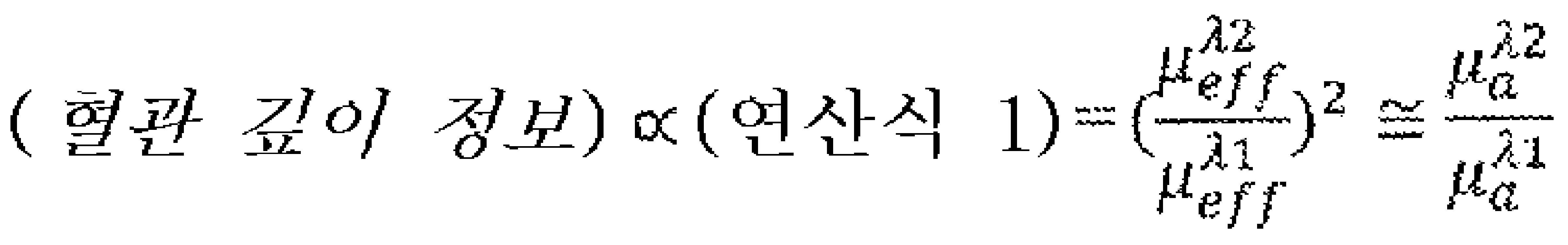
연산식 1에서, μeff는 유효 감쇠 계수이며, λ1과 λ2는 상기 제1 파장이며, μa는 흡수 계수이다.
[수학식 13]
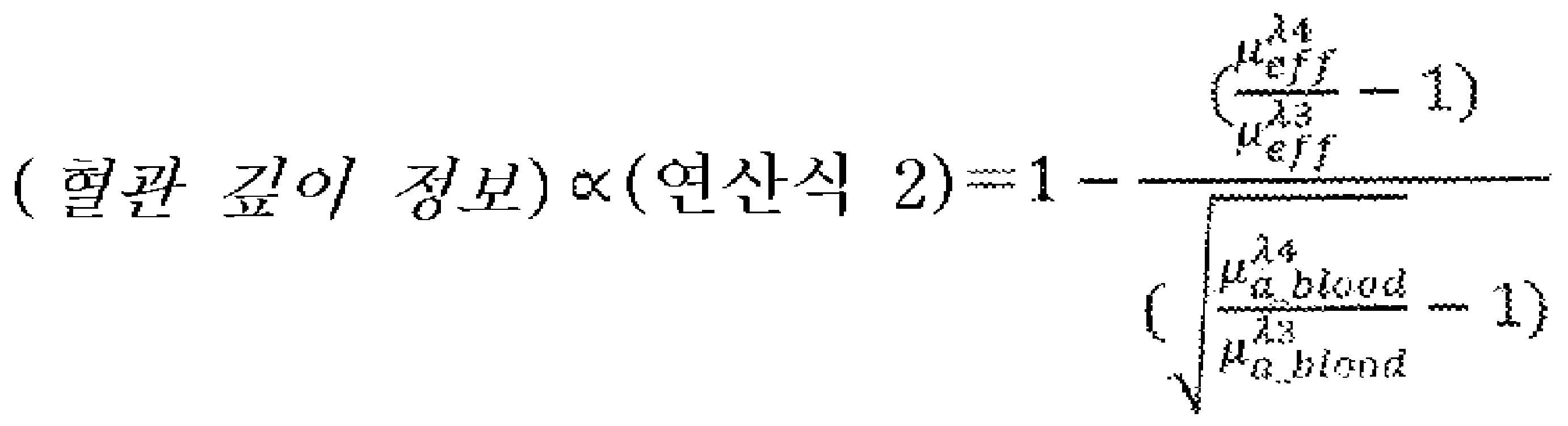
연산식 2에서, μeff는 유효 감쇠 계수이며, λ3은 상기 제1 파장이며, λ4는 상기 제2 파장이며, μa는 흡수 계수이다.4. The method according to any one of claims 1 to 3,
the control unit
A blood vessel detecting device for calculating the blood vessel depth information by Equation 1 or Equation 2.
[Equation 12]
In Equation 1, μeff is an effective attenuation coefficient, λ1 and λ2 are the first wavelengths, and μa is an absorption coefficient.
[Equation 13]
In Equation 2, μeff is the effective attenuation coefficient, λ3 is the first wavelength, λ4 is the second wavelength, and μa is the absorption coefficient.
상기 제어부는
상기 혈관 각도 정보를 연산식 3 또는 연산식 4에 의해 산출하는, 혈관 검지 장치.
[수학식 14]

연산식 3에서, In(n는 상기 광 강도 검출부의 수)는 제n 의 광 강도 검출부에서 검출된 광 강도며, λ5는 상기 제3 파장이다.
[수학식 15]

연산식 4에서, 분자는 유효 감쇠 계수(μeff)의 변동 계수(CV)이며, 분모는 광 강도(In)(n는 상기 광 강도 검출부의 수)의 변동 계수(CV)이며, λ6은 상기 제3 파장이며, λ7은 상기 제1 파장이다.5. The method according to any one of claims 1 to 4,
the control unit
A blood vessel detecting device for calculating the blood vessel angle information using Equation 3 or Equation 4.
[Equation 14]
In Equation 3, I n (n is the number of the light intensity detecting section) is the light intensity detected by the n-th light intensity detecting section, and λ5 is the third wavelength.
[Equation 15]
In Equation 4, the numerator is the coefficient of variation (CV) of the effective attenuation coefficient (μeff), the denominator is the coefficient of variation (CV) of the light intensity (I n ) (n is the number of the light intensity detection units), and λ6 is the a third wavelength, and λ7 is the first wavelength.
상기 조사부는 조사면에 조사광의 직진성을 높이기 위한 방향 조정부를 가지며,
상기 방향 조정부는 핀홀 또는 렌즈를 가지는 것을 특징으로 하는, 혈관 검지 장치.6. The method according to any one of claims 1 to 5,
The irradiation unit has a direction adjustment unit for increasing the straightness of the irradiation light on the irradiation surface,
The direction adjustment unit, characterized in that having a pinhole or a lens, blood vessel detection device.
상기 광의 조사 위치에서 소정 간격을 두고, 혹은, 연속적인 위치에서의 상기 피검체에서 방출되는 1 이상의 위치의 광 강도를 검출하고,
상기 제1 파장 및 상기 제2 파장의 일방 혹은 쌍방의 복수의 파장의 광 강도에서 혈관 깊이 정보를 산출하고,
상기 제1 파장 및 상기 제3 파장의 일방 혹은 쌍방의 1 이상의 광 강도에서 혈관 각도 정보를 산출하고,
상기 혈관 깊이 정보와 상기 혈관 각도 정보에 기반하여, 측정에 적합한 위치를 판단하는, 혈관 검지 방법.Light of a first wavelength having a small absorption by hemoglobin or water, light of a second wavelength having greater absorption by hemoglobin or water than the first wavelength, and light of a third wavelength having less absorption by hemoglobin irradiate at a certain location,
Detecting the light intensity of one or more positions emitted from the subject at a predetermined interval from the irradiation position of the light or at a continuous position,
calculating blood vessel depth information from light intensities of a plurality of wavelengths of one or both of the first wavelength and the second wavelength;
calculating blood vessel angle information from one or more light intensities of one or both of the first wavelength and the third wavelength;
Based on the blood vessel depth information and the blood vessel angle information, determining a location suitable for measurement, a blood vessel detection method.
Applications Claiming Priority (3)
| Application Number | Priority Date | Filing Date | Title |
|---|---|---|---|
| JP2020011512A JP2021117143A (en) | 2020-01-28 | 2020-01-28 | Blood vessel detector and method therefor |
| JPJP-P-2020-011512 | 2020-01-28 | ||
| PCT/JP2021/002407 WO2021153490A1 (en) | 2020-01-28 | 2021-01-25 | Blood vessel detection device and method therefor |
Publications (1)
| Publication Number | Publication Date |
|---|---|
| KR20220134576A true KR20220134576A (en) | 2022-10-05 |
Family
ID=77078263
Family Applications (1)
| Application Number | Title | Priority Date | Filing Date |
|---|---|---|---|
| KR1020227029064A KR20220134576A (en) | 2020-01-28 | 2021-01-25 | Blood vessel detection device and method therefor |
Country Status (4)
| Country | Link |
|---|---|
| US (1) | US20230058347A1 (en) |
| JP (1) | JP2021117143A (en) |
| KR (1) | KR20220134576A (en) |
| WO (1) | WO2021153490A1 (en) |
Citations (1)
| Publication number | Priority date | Publication date | Assignee | Title |
|---|---|---|---|---|
| WO2014087825A1 (en) | 2012-12-06 | 2014-06-12 | 国立大学法人北海道大学 | Non-invasive biolipid concentration meter, non-invasive biolipid metabolism measuring device, non-invasive method for measuring biolipid concentration, and non-invasive method for examining biolipid metabolism |
Family Cites Families (6)
| Publication number | Priority date | Publication date | Assignee | Title |
|---|---|---|---|---|
| WO2010056538A1 (en) * | 2008-10-29 | 2010-05-20 | Tim Maguire | An automated vessel puncture device using three-dimensional(3d) near infrared (nir) imaging and a robotically driven needle |
| JP5681915B2 (en) * | 2010-03-27 | 2015-03-11 | 旭光電機株式会社 | Blood collection device |
| JP6442826B2 (en) * | 2013-12-27 | 2018-12-26 | セイコーエプソン株式会社 | Blood component analysis method and blood component analyzer |
| US10165955B2 (en) * | 2014-02-06 | 2019-01-01 | Reuven Gladshtein | Obtaining cardiovascular parameters using arterioles related transient time |
| KR102531994B1 (en) * | 2017-12-29 | 2023-05-15 | 삼성전자주식회사 | Apparatus and method for measuring biological components |
| JP7093963B2 (en) * | 2018-05-22 | 2022-07-01 | メディカルフォトニクス株式会社 | Blood vessel detector |
-
2020
- 2020-01-28 JP JP2020011512A patent/JP2021117143A/en active Pending
-
2021
- 2021-01-25 US US17/793,566 patent/US20230058347A1/en active Pending
- 2021-01-25 KR KR1020227029064A patent/KR20220134576A/en unknown
- 2021-01-25 WO PCT/JP2021/002407 patent/WO2021153490A1/en active Application Filing
Patent Citations (1)
| Publication number | Priority date | Publication date | Assignee | Title |
|---|---|---|---|---|
| WO2014087825A1 (en) | 2012-12-06 | 2014-06-12 | 国立大学法人北海道大学 | Non-invasive biolipid concentration meter, non-invasive biolipid metabolism measuring device, non-invasive method for measuring biolipid concentration, and non-invasive method for examining biolipid metabolism |
Also Published As
| Publication number | Publication date |
|---|---|
| WO2021153490A1 (en) | 2021-08-05 |
| JP2021117143A (en) | 2021-08-10 |
| US20230058347A1 (en) | 2023-02-23 |
Similar Documents
| Publication | Publication Date | Title |
|---|---|---|
| JP5607358B2 (en) | Measurement of tissue oxygenation | |
| KR101860605B1 (en) | System for noninvasive optical measurements of physiological properties in tissue | |
| EP2948052B1 (en) | Deep tissue flowmetry using diffuse speckle contrast analysis | |
| JP7458078B2 (en) | Tissue measurement sensor | |
| US20120220844A1 (en) | Regional Saturation Using Photoacoustic Technique | |
| JP2010508056A (en) | System and method for in vivo measurement of biological parameters | |
| JP2006516207A (en) | Photoacoustic analysis method and apparatus | |
| JP5594787B2 (en) | Optical detection method and apparatus for optically detecting joint state | |
| CN111956234A (en) | Accurate blood oxygen saturation measuring method and device based on photoacoustic technology | |
| WO2019225612A1 (en) | Blood vessel detection device and method therefor | |
| US10595755B2 (en) | System and method for monitoring glucose level | |
| JP5662700B2 (en) | Biological light measurement device and biological light measurement method | |
| JP2007007267A (en) | Bone density measuring equipment | |
| EP2866654A1 (en) | Real-time tumor perfusion imaging during radiation therapy delivery | |
| TWI773713B (en) | Lipid measurement device and method therefor | |
| KR20220134576A (en) | Blood vessel detection device and method therefor | |
| JP4272024B2 (en) | Optical biological measurement device | |
| KR20200138332A (en) | Method and apparatus for testing neurovascular bonds in a patient's eye | |
| RU2770566C1 (en) | Method for non-invasive determination of the content of lipids in a person | |
| KR20010071588A (en) | A device for evaluating blood system properties | |
| KR102207022B1 (en) | Optoacoustic method comprising measuring light having a predefined wavelength range to determine the properties of a heterogeneous sample | |
| RU2545814C1 (en) | Method of determining physical-biological parameters of skin and concentration of haemoglobin derivatives in blood | |
| JP2022149431A (en) | Device and method for measuring total protein concentration |