KR20220134078A - Cooking appliance - Google Patents
Cooking appliance Download PDFInfo
- Publication number
- KR20220134078A KR20220134078A KR1020210039250A KR20210039250A KR20220134078A KR 20220134078 A KR20220134078 A KR 20220134078A KR 1020210039250 A KR1020210039250 A KR 1020210039250A KR 20210039250 A KR20210039250 A KR 20210039250A KR 20220134078 A KR20220134078 A KR 20220134078A
- Authority
- KR
- South Korea
- Prior art keywords
- main pipe
- burner
- unit
- cooktop
- pipe
- Prior art date
Links
- 238000010411 cooking Methods 0.000 title claims abstract description 187
- 238000010438 heat treatment Methods 0.000 claims description 43
- 238000000034 method Methods 0.000 claims description 18
- 239000000446 fuel Substances 0.000 claims description 17
- 239000007789 gas Substances 0.000 description 87
- 235000013305 food Nutrition 0.000 description 24
- 238000004519 manufacturing process Methods 0.000 description 11
- 230000008569 process Effects 0.000 description 10
- 230000005611 electricity Effects 0.000 description 9
- 230000000694 effects Effects 0.000 description 6
- 235000021186 dishes Nutrition 0.000 description 5
- 230000006698 induction Effects 0.000 description 4
- 238000009423 ventilation Methods 0.000 description 4
- 230000008901 benefit Effects 0.000 description 3
- 239000002131 composite material Substances 0.000 description 3
- 238000001816 cooling Methods 0.000 description 3
- 230000008878 coupling Effects 0.000 description 3
- 238000010168 coupling process Methods 0.000 description 3
- 238000005859 coupling reaction Methods 0.000 description 3
- 238000009434 installation Methods 0.000 description 3
- 230000008859 change Effects 0.000 description 2
- 238000002485 combustion reaction Methods 0.000 description 2
- 230000014509 gene expression Effects 0.000 description 2
- 230000005484 gravity Effects 0.000 description 2
- 238000005192 partition Methods 0.000 description 2
- 241000251468 Actinopterygii Species 0.000 description 1
- UGFAIRIUMAVXCW-UHFFFAOYSA-N Carbon monoxide Chemical compound [O+]#[C-] UGFAIRIUMAVXCW-UHFFFAOYSA-N 0.000 description 1
- 235000021168 barbecue Nutrition 0.000 description 1
- 235000008429 bread Nutrition 0.000 description 1
- 229910002091 carbon monoxide Inorganic materials 0.000 description 1
- 238000004140 cleaning Methods 0.000 description 1
- 238000007599 discharging Methods 0.000 description 1
- 239000000428 dust Substances 0.000 description 1
- 238000005516 engineering process Methods 0.000 description 1
- 230000002349 favourable effect Effects 0.000 description 1
- 239000000463 material Substances 0.000 description 1
- 230000004048 modification Effects 0.000 description 1
- 238000012986 modification Methods 0.000 description 1
- 238000000638 solvent extraction Methods 0.000 description 1
- XLYOFNOQVPJJNP-UHFFFAOYSA-N water Substances O XLYOFNOQVPJJNP-UHFFFAOYSA-N 0.000 description 1
Images


Classifications
-
- F—MECHANICAL ENGINEERING; LIGHTING; HEATING; WEAPONS; BLASTING
- F24—HEATING; RANGES; VENTILATING
- F24C—DOMESTIC STOVES OR RANGES ; DETAILS OF DOMESTIC STOVES OR RANGES, OF GENERAL APPLICATION
- F24C15/00—Details
- F24C15/10—Tops, e.g. hot plates; Rings
- F24C15/108—Mounting of hot plate on worktop
-
- A—HUMAN NECESSITIES
- A47—FURNITURE; DOMESTIC ARTICLES OR APPLIANCES; COFFEE MILLS; SPICE MILLS; SUCTION CLEANERS IN GENERAL
- A47J—KITCHEN EQUIPMENT; COFFEE MILLS; SPICE MILLS; APPARATUS FOR MAKING BEVERAGES
- A47J37/00—Baking; Roasting; Grilling; Frying
- A47J37/06—Roasters; Grills; Sandwich grills
- A47J37/0623—Small-size cooking ovens, i.e. defining an at least partially closed cooking cavity
- A47J37/0629—Small-size cooking ovens, i.e. defining an at least partially closed cooking cavity with electric heating elements
-
- A—HUMAN NECESSITIES
- A47—FURNITURE; DOMESTIC ARTICLES OR APPLIANCES; COFFEE MILLS; SPICE MILLS; SUCTION CLEANERS IN GENERAL
- A47J—KITCHEN EQUIPMENT; COFFEE MILLS; SPICE MILLS; APPARATUS FOR MAKING BEVERAGES
- A47J37/00—Baking; Roasting; Grilling; Frying
- A47J37/06—Roasters; Grills; Sandwich grills
- A47J37/0623—Small-size cooking ovens, i.e. defining an at least partially closed cooking cavity
- A47J37/0647—Small-size cooking ovens, i.e. defining an at least partially closed cooking cavity with gas burners
-
- F—MECHANICAL ENGINEERING; LIGHTING; HEATING; WEAPONS; BLASTING
- F24—HEATING; RANGES; VENTILATING
- F24C—DOMESTIC STOVES OR RANGES ; DETAILS OF DOMESTIC STOVES OR RANGES, OF GENERAL APPLICATION
- F24C3/00—Stoves or ranges for gaseous fuels
- F24C3/08—Arrangement or mounting of burners
- F24C3/085—Arrangement or mounting of burners on ranges
-
- F—MECHANICAL ENGINEERING; LIGHTING; HEATING; WEAPONS; BLASTING
- F24—HEATING; RANGES; VENTILATING
- F24C—DOMESTIC STOVES OR RANGES ; DETAILS OF DOMESTIC STOVES OR RANGES, OF GENERAL APPLICATION
- F24C7/00—Stoves or ranges heated by electric energy
- F24C7/06—Arrangement or mounting of electric heating elements
- F24C7/067—Arrangement or mounting of electric heating elements on ranges
Abstract
Description
본 발명은 조리기기에 관한 것으로, 더욱 상세하게는 오븐부와 쿡탑부를 함께 구비하는 조리기기에 관한 것이다.The present invention relates to a cooking appliance, and more particularly, to a cooking appliance having an oven unit and a cooktop unit together.
조리기기는, 음식물을 요리하기 위한 가전기기의 하나로써 주방 공간에 설치되어 사용자의 의도에 따라 음식물을 요리하는 기기이다. 이러한 조리기기는 사용되는 열원 또는 형태, 연료의 종류에 따라 다양하게 분류할 수 있다.A cooking appliance is one of home appliances for cooking food and is installed in a kitchen space to cook food according to a user's intention. These cooking appliances may be classified in various ways according to the type of heat source or type used, and fuel.
조리기기를 음식물을 조리하는 형태에 따라 분류하여 보면, 음식물이 놓이는 공간의 형태에 따라 개방형과 밀폐형 조리기기로 분류할 수 있다. 밀폐형 조리기기에는 오븐, 전자레인지 등이 있으며, 개방형 조리기기에는 쿡탑, 홉, 그리들 등이 있다.When cooking appliances are classified according to a type of cooking, they can be classified into open-type and closed-type cooking appliances according to the shape of a space in which food is placed. The closed cooking appliance includes an oven, a microwave oven, and the like, and the open cooking appliance includes a cooktop, a hop, a griddle, and the like.
밀폐형 조리기기는, 음식물이 위치하는 공간을 차폐하고, 차폐된 공간을 가열하여 음식물을 요리하는 조리기기이다. 밀폐형 조리기기에는, 음식물이 놓이면서 음식물을 요리하고자 할 때 차폐되는 공간인 조리실이 제공된다. 이러한 조리실은, 실질적으로 음식물이 요리되는 공간이 된다.The sealed cooking appliance is a cooking appliance that shields a space in which food is located and heats the shielded space to cook food. In the sealed cooking appliance, a cooking chamber, which is a space that is shielded when food is placed while cooking food, is provided. Such a cooking chamber becomes a space in which food is substantially cooked.
상기 밀폐형 조리기기는, 열원(熱源)의 종류에 따라 가스 오븐과 전기 오븐으로 대별된다. 가스 오븐은, 가스를 연료로 사용하게 되며, 다수의 버너에 가스를 공급하여 점화시킴으로써 공급되는 가스가 타면서 발생되는 불꽃에 의해 음식물을 요리하는 방식을 취하게 된다. 전기 오븐은, 가스 오븐과 달리 전기를 열원으로 하며, 다수의 히터가 작동되면서 히터에서 발산되는 열에 의해 음식물을 요리하는 방식을 취하게 된다.The sealed cooking appliance is roughly classified into a gas oven and an electric oven according to a type of a heat source. The gas oven uses gas as a fuel, and by supplying gas to a plurality of burners and igniting the gas oven, food is cooked by a flame generated while the supplied gas is burned. Unlike a gas oven, an electric oven uses electricity as a heat source and cooks food by heat emitted from the heaters while a plurality of heaters are operated.
밀폐형 조리기기에는, 조리실을 선택적으로 개폐하는 도어가 회동 가능하게 제공될 수 있다. 도어는, 내부에 조리실이 형성된 본체와 도어 사이에 마련되는 도어 힌지에 의해 본체에 회동 가능하게 설치되며, 도어 힌지를 통해 본체와 결합된 부분을 중심으로 회동함으로써 조리실을 선택적으로 개폐할 수 있다.In the sealed cooking appliance, a door for selectively opening and closing the cooking chamber may be rotatably provided. The door is rotatably installed on the main body by a door hinge provided between the main body in which the cooking chamber is formed and the door, and the cooking chamber can be selectively opened and closed by rotating around a portion coupled to the main body through the door hinge.
상기 도어에 의해 개폐되는 조리실의 내부 공간에는 열원이 제공되어 조리실을 가열한다. 이러한 열원으로는 가스버너 또는 전기히터 등이 이용될 수 있다.A heat source is provided to the inner space of the cooking compartment opened and closed by the door to heat the cooking compartment. As such a heat source, a gas burner or an electric heater may be used.
근래에는 밀폐형 조리기기와 개방형 조리기기가 동시에 설치되어 다수의 열원이 조합되면서 다양한 음식물의 요리 및 다수의 음식물을 동시에 요리할 수 있는 복합조리기기가 제안되고 있다. 이러한 다수의 열원이 설치되는 조리기기에는, 다수의 열원 및 전장 부품을 냉각하기 위한 냉각 공기의 유로가 동반된다.In recent years, a closed-type cooking device and an open-type cooking device are installed at the same time to combine a plurality of heat sources, and a complex cooking device capable of cooking various foods and cooking a plurality of foods at the same time has been proposed. A cooking appliance in which such a plurality of heat sources are installed is accompanied by a flow path of cooling air for cooling the plurality of heat sources and electronic components.
복합조리기기에서는, 밀폐형 조리기기의 상측에 개방형 조리기기가 위치된다. 또한 개방형 조리기기에는, 복수 개의 히터 또는 버너가 설치되어 동시에 다수의 요리가 가능하도록 설치된다.In the combined cooking appliance, an open cooking appliance is positioned above the closed cooking appliance. In addition, a plurality of heaters or burners are installed in the open cooking appliance to enable a plurality of dishes at the same time.
즉 사용자가 바비큐 요리나 빵 등과 같은 오븐요리, 생선구이와 같이 구이요리를 할 때에는 밀폐형 조리기기를 이용하여 조리를 하게 되고, 음식물을 용기에 담아서 가열하는 일반요리를 할 때는 상부에 노출되어 있는 개방형 조리기기를 이용하여 요리를 하게 된다.In other words, when the user cooks barbecue dishes, oven dishes such as bread, or grilling dishes such as grilled fish, he uses a closed cooking device. Cooking is done using cooking equipment.
개방형 조리기기 중 대표적으로 많이 이용되는 것은, 가스레인지 형태의 개방형 조리기기로서, 버너에 의해 가스가 연소될 때 발생되는 화염을 이용하여 음식물을 조리하는 기기이다.One of the most commonly used open cookers is a gas range type open cooker that cooks food using a flame generated when gas is burned by a burner.
이러한 형태의 개방형 조리기기에 구비되는 버너는, 크게 버너바디, 버너헤드 및 버너헤드캡을 포함하는 구성을 갖는 것이 일반적이다.A burner provided in this type of open cooking appliance generally has a configuration including a burner body, a burner head, and a burner head cap.
이에 따르면, 개방형 조리기기의 외형을 형성하는 쿡탑케이스 내부에 가스가 공급되는 유로가 형성된 버너바디가 고정되게 설치되고, 버너바디의 상부에는 유로를 통해 공급된 가스가 배출되는 버너헤드가 설치되며, 버너헤드캡은 버너헤드의 상부에 설치된다.According to this, a burner body having a flow path through which gas is supplied is fixedly installed inside the cooktop case forming the outer shape of the open cooking appliance, and a burner head through which the gas supplied through the flow path is discharged is installed on the upper portion of the burner body, The burner head cap is installed on the upper part of the burner head.
버너바디에는, 가스의 공급을 위한 가스공급관 및 가스의 분사를 위한 노즐 등이 장착될 수 있다. 그리고 버너헤드는 개방형 조리기기의의 상면을 정의하는 부재, 예를 들면 탑플레이트의 상면에 위치할 수 있고, 버너헤드캡이 버너헤드의 상측에 안착된다.A gas supply pipe for supplying gas and a nozzle for injecting gas may be mounted on the burner body. In addition, the burner head may be located on a member defining the upper surface of the open cooking appliance, for example, the upper surface of the top plate, and the burner head cap is seated on the upper side of the burner head.
최근에는, 전기를 이용한 쿡탑 형태의 개방형 조리기기의 이용이 증가되고 있다. 전기를 이용하는 대표적인 조리기기로는 유도가열 조리기기가 있다. 일반적으로, 유도 가열 조리기는 워킹 코일(Working coil) 또는 가열 코일에 고주파의 전류를 흐르게 하고, 이로 인해 발생하는 강력한 자력선이 조리용기를 통과할 때 와류전류(Eddy current)가 흘러 용기 자체가 가열되는 방식으로 조리 기능을 수행하는 전기 조리 장치이다.Recently, the use of cooktop type open cooking appliances using electricity is increasing. A typical cooking appliance using electricity is an induction heating cooking appliance. In general, induction heating cookers flow a high-frequency current to a working coil or a heating coil, and when a strong magnetic force line generated by this passes through a cooking vessel, an eddy current flows and the vessel itself is heated. It is an electric cooking device that performs a cooking function in this way.
그 외에 전기를 이용하는 조리기기로 전열 방식으로 가열하는 하이라이트(High light)나 핫플레이트(Hot plate) 등과 같은 가열 조리기기가 적용될 수도 있다.In addition, as a cooking device using electricity, a heating cooking device such as a high light or a hot plate that is heated by an electric heat method may be applied.
최근 들어 조리 시간이 빠르고 청소가 용이하다는 장점 등으로 인해, 전기를 이용하는 개방형 조리기기(이하, "전기레인지라 한다)가 빠른 속도로 가스를 이용하는 개방형 조리기기(이하, "가스레인지"라 한다)를 대체하고 있다.Recently, due to the advantages of fast cooking time and easy cleaning, an open cooking appliance using electricity (hereinafter referred to as an "electric range") is an open cooking appliance using gas at a high speed (hereinafter referred to as a "gas range") is replacing
전기레인지는, 가스레인지와 달리 일산화탄소 같은 유해가스를 내뿜지 않고 미세먼지가 심한 날에도 환기 걱정 없이 사용할 수 있다는 장점이 있다. 화력에 있어서도 전기레인지가 가스레인지를 넘어서고 있으며, 열효율에 있어서도 전기레인지가 가스레인지에 비해 더 우수하다. 또한 가스레인지 청소는 매번 하기 번거로운 반면, 전기레인지는 요리를 끝낼 때마다 쉽게 청소할 수 있다.Unlike gas stoves, electric stoves do not emit harmful gases such as carbon monoxide and can be used without worrying about ventilation even on days with severe fine dust. In terms of thermal power, electric ranges surpass gas ranges, and in terms of thermal efficiency, electric ranges are superior to gas ranges. Also, while it is cumbersome to clean the gas stove every time, the electric stove can be easily cleaned every time you finish cooking.
이에 비해, 가스레인지는 전기 공급이 이루어지지 않는 환경에서도 이용이 가능하며, 전기레인지에 비해 연료비가 상대적으로 적게 드는 장점이 있다. 또한 가스레인지는, 불꽃을 이용하므로, 전기레인지에서 이루어지지 못하는 다양한 요리를 할 수 있는 등 사용 범위가 전자레인지에 비해 넓을 뿐 아니라, 전기레인지에 비해 비교적 저렴하기도 하다.On the other hand, a gas range can be used even in an environment where electricity is not supplied, and has the advantage of having a relatively low fuel cost compared to an electric range. In addition, since the gas range uses a flame, the range of use is wider than that of a microwave oven, such as being able to cook various dishes that cannot be done in an electric range, and it is also relatively inexpensive compared to an electric range.
따라서 최근에도, 전기레인지가 개방형 조리기기로 적용된 복합조리기기와 가스레인지가 개방형 조리기기로 적용된 복합조리기기가 여전히 함께 출시되고 있다.Therefore, even recently, a combined cooking appliance in which an electric range is applied as an open cooking appliance and a combined cooking appliance in which a gas range is applied as an open cooking appliance are still being released together.
통상적으로, 복합조리기기의 조립 공정에서는 밀폐형 조리기기의 조립이 먼저 이루어진 후, 개방형 조리기기의 조립이 마지막에 이루어진다. 즉 밀폐형 조리기기의 조립이 먼저 이루어진 상태에서, 그 위에 전기레인지나 가스레인지가 얹혀지는 형태로 복합조리기기의 조립이 이루어질 수 있다.In general, in the assembly process of the combined cooking appliance, the closed cooking appliance is assembled first, and then the open cooking appliance is assembled last. That is, in a state in which the assembly of the sealed cooking appliance is made first, the assembly of the complex cooking appliance may be made in a form in which an electric range or a gas range is placed thereon.
복합조리기기에 전기레인지가 적용된 경우, 미리 제작된 전기레인지가 조립 공정 중 마지막 공정에서 복합조리기기의 상부에 얹혀지며 복합조리기기의 조립이 완료될 수 있다.When the electric range is applied to the multi-purpose cooking device, the pre-fabricated electric range is placed on the top of the multi-purpose cooking device in the last step of the assembly process, and the assembly of the multi-purpose cooking device can be completed.
일반적으로 가스레인지는, 밸브, 매니폴드, 파이프, 버너, 탑플레이트 등 다양한 부품의 조합으로 마련된다. 복합조리기기에 가스레인지가 적용된 경우, 복합조리기기의 상부에 밸브, 매니폴드, 파이프, 버너 등이 조립된 후, 마지막 조립 공정에서 탑플레이트가 복합조리기기의 상부에 얹혀지며 복합조리기기의 조립이 완료될 수 있다.In general, a gas range is provided with a combination of various parts such as a valve, a manifold, a pipe, a burner, and a top plate. When a gas range is applied to a complex cooker, the valve, manifold, pipe, burner, etc. are assembled on the upper part of the complex cooker, and then the top plate is placed on the upper part of the complex cooker in the final assembly process to assemble the complex cooker This can be done.
선행문헌1(미국 등록특허 제8402962호)에는, 복합조리기기의 상부에 얹혀지는 가스레인지의 구조가 개시되어 있다.Prior Document 1 (US Patent No. 8402962) discloses a structure of a gas range placed on an upper portion of a combined cooking appliance.
선행문헌1에 개시된 탑버너는 복수개의 화구를 포함하며, 각 화구에는 버너 어셈블리가 각각 배치된다. 이러한 탑버너에서는, 공통의 공급파이프으로부터 분지된 튜브에 버너 어셈블리가 결합된다.The top burner disclosed in
선행문헌1에 개시된 탑버너에서, 각각의 버너 어셈블리에 튜브를 연결하는 작업은, 오븐의 상부에 탑버너를 조립하는 공정에서 이루어진다. 이러한 탑버너 조립 공정에서는, 작업자가 각각의 버너 어셈블리를 분지된 튜브를 연결하는 작업이 필요하다.In the top burner disclosed in
그러나 오븐의 상부에 탑버너를 설치하면서 버너 어셈블리와 튜브를 연결하는 작업은 쉬운 작업이 아니고, 상당히 난이도가 높은 작업이다. 또한 선행문헌1에 개시된 탑버너에서는, 화구 수만큼의 조립 공수가 투입되어야 하므로, 탑버너 조립 작업의 어려움은 배가될 수밖에 없게 된다.However, the operation of connecting the burner assembly and the tube while installing the top burner on the upper part of the oven is not an easy task, and it is a very difficult task. In addition, in the top burner disclosed in
또한 상기와 같이 복합조리기기에 가스레인지가 적용된 경우, 버너의 화구 수만큼의 조립 공수가 투입되어야 하므로, 전기레인지가 적용된 복합조리기기의 생산시에 비해 조립 라인의 공수 및 투입 인원이 증가될 수밖에 없게 된다.In addition, when a gas range is applied to a combined cooking device as described above, as many assembling man-hours must be input as many as the number of craters of the burner, so compared to the production of a composite cooking device to which an electric range is applied, the number of labor and input manpower of the assembly line is inevitably increased. there will be no
따라서 전기레인지가 적용된 복합조리기기를 생산하던 조립 라인에서 가스레인지가 적용된 복합조리기기를 생산할 경우, 또는 그 반대로 가스레인지가 적용된 복합조리기기를 생산하던 조립 라인에서 전기레인지가 적용된 복합조리기기를 생산할 경우, 조립 라인의 공수 및 투입 인원에 큰 변동이 발생될 수밖에 없게 된다.Therefore, if an assembly line that produced a combined cooker with an electric range applied a gas range was produced, or conversely, an assembly line that produced a combined cooker equipped with a gas range could produce a combined cooker with an electric range. In this case, large fluctuations in the number of labor and input personnel of the assembly line will inevitably occur.
즉 각 조립 라인에서 이전에 생산하던 형태의 조리기기와 다른 형태의 조리기기를 조립하게 될 경우, 조립 라인의 공수 및 투입 인원에 큰 변동이 발생되며 조립 라인의 생산 효율이 낮아지는 문제점이 발생된다.That is, when each assembly line assembles a cooking device of a type different from the type of cooking device previously produced, a large change occurs in the number of labor and input personnel of the assembly line, and the production efficiency of the assembly line is lowered. .
본 발명은 복합조리기기에 가스레인지가 적용된 경우에 가스레인지의 조립이 쉽고 효율적으로 이루어질 수 있도록 구조가 개선된 조리기기를 제공하는데 그 목적이 있다.An object of the present invention is to provide a cooking appliance with an improved structure so that the assembly of the gas range can be easily and efficiently performed when the gas range is applied to the composite cooking appliance.
또한 본 발명의 다른 목적은, 하나의 조립 라인에서 가스레인지의 조립과 전기레인지의 조립이 모두 효율적으로 이루어질 수 있도록 구조가 개선된 조리기기를 제공하는데 있다.Another object of the present invention is to provide a cooking appliance with an improved structure so that both the gas range assembly and the electric range assembly can be efficiently performed in one assembly line.
또한 본 발명의 다른 목적은, 가스레인지를 조립 중이던 조립 라인에서 다른 종류의 조리기기를 조립하거나 그 반대의 경우에도 해당 조립 라인의 생산 효율이 효과적으로 유지될 수 있도록 구조가 개선된 조리기기를 제공하는데 있다.Another object of the present invention is to provide a cooking appliance with an improved structure so that the production efficiency of the assembly line can be effectively maintained even in the case of assembling other types of cooking devices on an assembly line in which a gas range is being assembled or vice versa. have.
상기 목적을 이루기 위한 본 발명의 일 실시 형태인 조리기기는, 쿡탑부를 구성하는 부품들이 미리 조립되어 하나의 독립적인 조립체를 형성하는 서브어셈블리를 포함하고, 이 서브어셈블리가 오븐부의 상부에 조립되어 쿡탑부를 형성하는 것을 특징으로 한다.A cooking appliance according to an embodiment of the present invention for achieving the above object includes a sub-assembly in which parts constituting a cook-top unit are pre-assembled to form an independent assembly, and the sub-assembly is assembled on the upper part of the oven unit to form a cooktop. It is characterized by forming wealth.
또한 본 발명의 다른 형태는, 오븐부의 상부에 쿡탑부가 배치되고, 오븐부에 고정되는 제1메인파이프와 쿡탑부에 고정되는 제2메인파이프가 분리 가능하게 연결되며, 제1메인파이프와 제2메인파이프가 연결되며 오븐부와 쿡탑부의 조립이 이루어지는 것을 특징으로 한다.In another aspect of the present invention, a cooktop unit is disposed on an upper portion of the oven unit, a first main pipe fixed to the oven unit and a second main pipe fixed to the cooktop unit are detachably connected to each other, and the first main pipe and the second The main pipe is connected and the oven unit and the cooktop unit are assembled.
본 발명의 일 측면에 따른 조리기기는: 내부에 조리실이 형성되는 캐비티를 포함하는 오븐부와; 상기 오븐부에 설치되어 연료 공급을 위한 유로를 형성하는 제1메인파이프; 및 상기 오븐부의 상부에 배치되어 상기 제1메인파이프와 연결되는 쿡탑부;를 포함하고, 상기 쿡탑부는, 상기 캐비티와의 사이에 상부공간이 형성되도록 상기 캐비티의 상부를 덮는 탑플레이트와; 적어도 일부분이 상기 상부공간에 배치되는 버너; 및 상기 제1메인파이프와 상기 버너 사이를 연결하는 제2메인파이프;를 포함하고, 상기 제1메인파이프는 상기 오븐부에 고정되며, 상기 제2메인파이프는 상기 쿡탑부에 고정되고, 상기 제1메인파이프와 상기 제2메인파이프가 분리 가능하게 연결될 수 있다.According to one aspect of the present invention, a cooking appliance includes: an oven unit including a cavity having a cooking chamber formed therein; a first main pipe installed in the oven unit to form a flow path for supplying fuel; and a cooktop portion disposed on the oven portion and connected to the first main pipe, wherein the cooktop portion includes: a top plate covering an upper portion of the cavity to form an upper space therebetween; a burner, at least a portion of which is disposed in the upper space; and a second main pipe connecting between the first main pipe and the burner, wherein the first main pipe is fixed to the oven unit, the second main pipe is fixed to the cooktop unit, and the second main pipe is fixed to the cooktop unit. The first main pipe and the second main pipe may be detachably connected.
또한 상기 탑플레이트와, 상기 탑플레이트에 결합되는 적어도 하나의 상기 버너, 및 상기 버너와 연결되는 제2메인파이프의 조합으로 서브어셈블리가 형성되고, 상기 오븐부와 분리된 상태의 상기 서브어셈블리에서, 상기 탑플레이트와 상기 버너 및 상기 제2메인파이프가 상기 오븐부와 분리되며 상기 제2메인파이프가 상기 제1메인파이프와 분리된 상태로 상기 탑플레이트와 상기 버너 및 상기 제2메인파이프가 하나의 조립체를 형성하는 것이 바람직하다.In addition, a subassembly is formed by a combination of the top plate, at least one burner coupled to the top plate, and a second main pipe connected to the burner, and in the subassembly separated from the oven unit, The top plate, the burner, and the second main pipe are separated from the oven unit, and the top plate, the burner, and the second main pipe are separated from the first main pipe. It is desirable to form an assembly.
또한 상기 제2메인파이프가 상기 제1메인파이프와 연결되며 상기 서브어셈블리가 상기 오븐부의 상부에 결합되어 상기 오븐부의 상부에 상기 쿡탑부가 형성되는 것이 바람직하다.In addition, it is preferable that the second main pipe is connected to the first main pipe and the sub-assembly is coupled to the upper part of the oven unit, so that the cooktop unit is formed on the upper part of the oven unit.
또한 상기 제1메인파이프는 상기 조리실보다 후방에 배치되고, 상기 제2메인파이프는 상기 탑플레이트의 하부에서 상기 제1메인파이프와 연결되는 것이 바람직하다.In addition, it is preferable that the first main pipe is disposed behind the cooking chamber, and the second main pipe is connected to the first main pipe under the top plate.
또한 상기 제1메인파이프는 상기 캐비티의 후방에서 상부방향으로 연장되고, 상기 서브어셈블리는 상기 캐비티를 상부에서 덮으며 상기 쿡탑부를 형성하고, 상기 제1메인파이프와 상기 제2메인파이프가 상하방향으로 연결되는 것이 바람직하다.In addition, the first main pipe extends upwardly from the rear of the cavity, the subassembly covers the cavity from the top to form the cooktop part, and the first main pipe and the second main pipe are vertically arranged It is preferable to be connected.
또한 상기 제2메인파이프는, 상기 탑플레이트의 하부에서 전후방향으로 연장되는 가로관부와; 상기 가로관부의 후방 단부로부터 하부방향으로 연장되는 세로관부; 및 상기 세로관부의 단부에 마련되어 상기 제1메인파이프와 상기 제2메인파이프를 연결시키는 연결부;를 포함하는 것이 바람직하다.In addition, the second main pipe may include a transverse pipe portion extending in the front-rear direction from the lower portion of the top plate; a vertical tube portion extending downwardly from the rear end of the horizontal tube portion; and a connecting portion provided at an end of the vertical tube portion to connect the first main pipe and the second main pipe.
또한 상기 세로관부와 상기 제1메인파이프가 일렬로 연결되는 것이 바람직하다.In addition, it is preferable that the vertical tube portion and the first main pipe are connected in a line.
또한 상기 쿡탑부는, 상기 제2메인파이프와 상기 버너 사이를 연결하는 적어도 하나의 버너파이프와; 상기 제2메인파이프로부터 분기되어 상기 제2메인파이프와 상기 버너파이프 사이를 연결하는 매니폴드와; 상기 버너파이프로부터 상기 버너로의 연료 공급을 조절하는 밸브;를 더 포함하고, 상기 버너파이프와 상기 매니폴드 및 상기 밸브가 상기 탑플레이트에 직간접적으로 고정되는 것이 바람직하다.The cooktop unit may include at least one burner pipe connecting the second main pipe and the burner; a manifold branching from the second main pipe and connecting the second main pipe and the burner pipe; It is preferable that the burner pipe, the manifold, and the valve are directly or indirectly fixed to the top plate, further comprising a valve for controlling the fuel supply from the burner pipe to the burner.
또한 상기 탑플레이트와, 적어도 하나의 상기 버너와, 상기 제2메인파이프와, 상기 버너파이프와, 상기 매니폴드, 및 상기 밸브의 조합으로 상기 서브어셈블리가 형성되고, 상기 오븐부와 분리된 상태의 상기 서브어셈블리에서, 상기 탑플레이트와 상기 버너와 상기 제2메인파이프가 상기 버너파이프와 상기 매니폴드 및 상기 밸브가 상기 오븐부와 분리된 상태로 하나의 조립체를 형성하는 것이 바람직하다.In addition, the subassembly is formed by a combination of the top plate, the at least one burner, the second main pipe, the burner pipe, the manifold, and the valve, and is separated from the oven unit. In the subassembly, it is preferable that the top plate, the burner, and the second main pipe form a single assembly in a state in which the burner pipe, the manifold, and the valve are separated from the oven unit.
또한 본 발명은 상기 쿡탑플레이트의 전방에 배치되어 상기 쿡탑가열부의 동작을 조절하는 조작부를 구비하는 컨트롤패널을 더 포함하고, 상기 컨트롤패널이 상기 쿡탑부와 결합되며 상기 컨트롤패널과 상기 쿡탑부의 조합으로 상기 서브어셈블리가 형성되는 것이 바람직하다.In addition, the present invention further includes a control panel disposed in front of the cooktop plate and having a manipulation unit for controlling the operation of the cooktop heating unit, wherein the control panel is coupled to the cooktop unit and is a combination of the control panel and the cooktop unit. Preferably, the subassembly is formed.
본 발명의 조리기기에 따르면, 오븐부의 상부에 서브어셈블리를 얹어 조립하고 분리된 두 메인파이프를 연결시키는 쉽고 단순한 조립 작업만으로 쿡탑부의 설치가 완료되도록 함으로써, 가스레인지를 구비하는 조리기기를 제조하기 위한 조립 작업이 쉽고 효율적으로 이루어질 수 있다.According to the cooking appliance of the present invention, by placing a sub-assembly on the upper part of the oven part and assembling it and connecting the two separated main pipes to complete the installation of the cooktop part, the cooking appliance having a gas range Assembly work can be done easily and efficiently.
또한 본 발명은, 상하방향으로 배치된 오븐과 가스레인지를 조립하여 복합조리기기를 제조하는 과정에서 버너를 일일이 연결하는 작업을 할 필요가 없도록 함으로써, 조립 작업의 난이도를 낮추고, 조리기기 조립 라인의 생산 효율이 더욱 향상될 수 있도록 하는 효과를 제공할 수 있다.In addition, the present invention reduces the difficulty of assembling work by assembling the oven and the gas range arranged in the vertical direction so that it is not necessary to connect the burners one by one in the process of manufacturing the composite cooking device, thereby reducing the difficulty of the assembly line. It can provide the effect that the production efficiency can be further improved.
또한 본 발명은, 하나의 조립 라인에서 가스레인지를 구비하는 조리기기의 조립과 전기레인지를 구비하는 조리기기의 조립이 모두 효율적으로 이루어질 수 있도록 하는 효과가 제공될 수 있다.In addition, the present invention can provide an effect of efficiently performing both the assembly of the cooking appliance including the gas range and the assembly of the cooking appliance including the electric range in one assembly line.
또한 본 발명은 가스레인지를 구비하는 조리기기를 조립 중이던 조립 라인에서 다른 종류의 조리기기를 조립하거나 그 반대의 경우에도 해당 조립 라인의 생산 효율이 효과적으로 유지될 수 있도록 하는 효과를 제공할 수 있다.In addition, the present invention can provide an effect of effectively maintaining the production efficiency of the assembly line even in the case of assembling other types of cooking devices on the assembly line in which the cooking devices including the gas range are being assembled or vice versa.
또한 본 발명은 가스레인지 형태의 쿡탑부와 전기레인지 형태의 쿡탑부가 모두 단순하고 쉬운 조립 작업만으로 설치될 수 있도록 함으로써, 하나의 조립 라인에서 다양한 형태의 조리기기에 대한 조립 작업이 효과적으로 이루어질 수 있도록 하면서도, 그 과정에서 조립 라인의 생산 효율이 효과적으로 유지될 수 있도록 하는 효과를 제공할 수 있다.In addition, the present invention allows both the gas range-type cooktop part and the electric range-type cooktop part to be installed with simple and easy assembly work, so that the assembly work for various types of cooking appliances can be effectively performed in one assembly line while , it can provide the effect that the production efficiency of the assembly line can be effectively maintained in the process.
도 1은 발명의 일 실시예에 따른 조리기기를 도시한 사시도이다.
도 2는 도 1에 도시된 조리기기의 정면도이다.
도 3은 도 1에 도시된 조리기기의 내부 구성을 보여주는 측단면도이다.
도 4는 도 1에 도시된 조리기기에서의 쿡탑부 및 컨트롤패널 분리 상태를 도시한 분해 사시도이다.
도 5는 도 1에 도시된 조리기기에서의 쿡탑부 분리 상태를 도시한 측단면도이다.
도 6은 도 5에 도시된 서브어셈블리를 확대하여 도시한 확대도이다.
도 7은 도 5에 도시된 조리기기에서의 쿡탑부 조립 상태를 도시한 측단면도이다.
도 8은 조리기기의 다른 예를 도시한 분해 사시도이다.1 is a perspective view illustrating a cooking appliance according to an embodiment of the present invention.
FIG. 2 is a front view of the cooking appliance shown in FIG. 1 .
FIG. 3 is a side cross-sectional view showing an internal configuration of the cooking appliance shown in FIG. 1 .
4 is an exploded perspective view illustrating a state in which the cooktop unit and the control panel are separated from the cooking appliance shown in FIG. 1 .
FIG. 5 is a side cross-sectional view illustrating a state in which the cooktop unit is separated from the cooking appliance shown in FIG. 1 .
FIG. 6 is an enlarged view illustrating the subassembly shown in FIG. 5 .
7 is a side cross-sectional view illustrating an assembly state of the cooktop unit in the cooking appliance shown in FIG. 5 .
8 is an exploded perspective view illustrating another example of the cooking appliance.
전술한 목적, 특징 및 장점은 첨부된 도면을 참조하여 상세하게 후술되며, 이에 따라 본 발명이 속하는 기술분야에서 통상의 지식을 가진 자가 본 발명의 기술적 사상을 용이하게 실시할 수 있을 것이다. 본 발명을 설명함에 있어서 본 발명과 관련된 공지 기술에 대한 구체적인 설명이 본 발명의 요지를 불필요하게 흐릴 수 있다고 판단되는 경우에는 상세한 설명을 생략한다. 이하, 첨부된 도면을 참조하여 본 발명에 따른 바람직한 실시예를 상세히 설명하기로 한다. 도면에서 동일한 참조부호는 동일 또는 유사한 구성요소를 가리키는 것으로 사용된다.The above-described objects, features and advantages will be described below in detail with reference to the accompanying drawings, and accordingly, those skilled in the art to which the present invention pertains will be able to easily implement the technical idea of the present invention. In describing the present invention, if it is determined that a detailed description of a known technology related to the present invention may unnecessarily obscure the gist of the present invention, the detailed description will be omitted. Hereinafter, preferred embodiments according to the present invention will be described in detail with reference to the accompanying drawings. In the drawings, the same reference numerals are used to indicate the same or similar components.
비록 제1, 제2 등이 다양한 구성요소들을 서술하기 위해서 사용되나, 이들 구성요소들은 이들 용어에 의해 제한되지 않음은 물론이다. 이들 용어들은 단지 하나의 구성요소를 다른 구성요소와 구별하기 위하여 사용하는 것으로, 특별히 반대되는 기재가 없는 한, 제1 구성요소는 제2 구성요소일 수도 있음은 물론이다.Although the first, second, etc. are used to describe various elements, these elements are not limited by these terms, of course. These terms are only used to distinguish one component from other components, and unless otherwise stated, the first component may be the second component, of course.
본 발명은 이하에서 개시되는 실시 예에 한정되는 것이 아니라 다양한 변경을 가할 수 있고 서로 다른 다양한 형태로 구현될 수 있다. 단지 본 실시 예는 본 발명의 개시가 완전하도록 하며 통상의 지식을 가진 자에게 발명의 범주를 완전하게 알려주기 위하여 제공되는 것이다. 따라서 본 발명은 이하에서 개시되는 실시예에 한정되는 것이 아니라, 어느 하나의 실시예의 구성과 다른 실시예의 구성을 서로 치환하거나 부가하는 것은 물론 본 발명의 기술적 사상과 범위에 포함되는 모든 변경, 균등물 내지 대체물을 포함하는 것으로 이해되어야 한다. The present invention is not limited to the embodiments disclosed below, and various changes may be made and may be implemented in various different forms. Only this embodiment is provided so as to complete the disclosure of the present invention and to fully inform those of ordinary skill in the scope of the invention. Therefore, the present invention is not limited to the embodiments disclosed below, and all changes and equivalents included in the technical spirit and scope of the present invention as well as substituting or adding the configuration of any one embodiment and the configuration of other embodiments to each other or substitutes.
첨부된 도면은 본 명세서에 개시된 실시 예를 쉽게 이해할 수 있도록 하기 위한 것일 뿐, 첨부된 도면에 의해 본 명세서에 개시된 기술적 사상이 제한되지 않으며, 본 발명의 사상 및 기술 범위에 포함되는 모든 변경, 균등물 내지 대체물을 포함하는 것으로 이해되어야 한다. 도면에서 구성요소들은 이해의 편의 등을 고려하여 크기나 두께가 과장되게 크거나 작게 표현될 수 있으나, 이로 인해 본 발명의 보호범위가 제한적으로 해석되어서는 아니 될 것이다.The accompanying drawings are only for easy understanding of the embodiments disclosed in the present specification, and the technical spirit disclosed in the present specification is not limited by the accompanying drawings, and all changes and equivalents included in the spirit and scope of the present invention It should be understood to include water or substitutes. In the drawings, in consideration of the convenience of understanding, the size or thickness may be exaggeratedly large or small, but the protection scope of the present invention should not be construed as being limited thereto.
본 명세서에서 사용한 용어는 단지 특정한 구현예나 실시예를 설명하기 위해 사용되는 것으로, 본 발명을 한정하려는 의도가 아니다. 그리고 단수의 표현은, 문맥상 명백하게 다르게 뜻하지 않는 한, 복수의 표현을 포함한다. 명세서에서 ~포함하다, ~이루어진다 등의 용어는 명세서 상에 기재된 특징, 숫자, 단계, 동작, 구성요소, 부품 또는 이들을 조합한 것이 존재함을 지정하려는 것이다. 즉 명세서에서 ~포함하다, ~이루어진다 등의 용어는. 하나 또는 그 이상의 다른 특징들이나 숫자, 단계, 동작, 구성요소, 부품 또는 이들이 조합한 것들의 존재 또는 부가 가능성을 미리 배제하지 않는 것으로 이해되어야 한다.The terms used herein are used only to describe specific embodiments or examples, and are not intended to limit the present invention. And singular expressions include plural expressions unless the context clearly dictates otherwise. In the specification, terms such as includes, consists of, etc. are intended to designate that the features, numbers, steps, operations, components, parts, or combinations thereof described in the specification exist. That is, in the specification, terms such as include and consist of. It should be understood that this does not preclude the possibility of addition or existence of one or more other features or numbers, steps, operations, components, parts, or combinations thereof.
제1, 제2 등과 같이 서수를 포함하는 용어는 다양한 구성요소들을 설명하는데 사용될 수 있지만, 상기 구성요소들은 상기 용어들에 의해 한정되지는 않는다. 상기 용어들은 하나의 구성요소를 다른 구성요소로부터 구별하는 목적으로만 사용된다.Terms including ordinal numbers such as first, second, etc. may be used to describe various elements, but the elements are not limited by the terms. The above terms are used only for the purpose of distinguishing one component from another.
어떤 구성요소가 다른 구성요소에 "연결되어" 있다거나 "접속되어" 있다고 언급된 때에는, 그 다른 구성요소에 직접적으로 연결되어 있거나 또는 접속되어 있을 수도 있지만, 중간에 다른 구성요소가 존재할 수도 있다고 이해되어야 할 것이다. 반면에, 어떤 구성요소가 다른 구성요소에 "직접 연결되어" 있다거나 "직접 접속되어" 있다고 언급된 때에는, 중간에 다른 구성요소가 존재하지 않는 것으로 이해되어야 할 것이다.When a component is referred to as being “connected” or “connected” to another component, it may be directly connected or connected to the other component, but it is understood that other components may exist in between. it should be On the other hand, when it is said that a certain element is "directly connected" or "directly connected" to another element, it should be understood that the other element does not exist in the middle.
어떤 구성요소가 다른 구성요소의 "상부에 있다"거나 "하부에 있다"고 언급된 때에는, 그 다른 구성요소의 바로 위에 배치되어 있는 것뿐만 아니라 중간에 다른 구성요소가 존재할 수도 있다고 이해되어야 할 것이다.When an element is referred to as "over" or "below" another element, it should be understood that other elements may be present in the middle as well as disposed directly on the other element. .
다르게 정의되지 않는 한, 기술적이거나 과학적인 용어를 포함해서 여기서 사용되는 모든 용어들은 본 발명이 속하는 기술 분야에서 통상의 지식을 가진 자에 의해 일반적으로 이해되는 것과 동일한 의미를 가지고 있다. 일반적으로 사용되는 사전에 정의되어 있는 것과 같은 용어들은 관련 기술의 문맥 상 가지는 의미와 일치하는 의미를 가지는 것으로 해석되어야 하며, 본 출원에서 명백하게 정의하지 않는 한, 이상적이거나 과도하게 형식적인 의미로 해석되지 않는다.Unless defined otherwise, all terms used herein, including technical or scientific terms, have the same meaning as commonly understood by one of ordinary skill in the art to which this invention belongs. Terms such as those defined in a commonly used dictionary should be interpreted as having a meaning consistent with the meaning in the context of the related art, and should not be interpreted in an ideal or excessively formal meaning unless explicitly defined in the present application. does not
조리기기가 바닥(floor)에 놓인 상태에서, 조리기기의 중심을 기준으로 도어가 설치된 방향을 전방으로 정의한다. 따라서 도어를 열고 조리기기 내부로 진입하는 방향은 후방이 된다. 편의상 이렇게 전방과 후방을 향하는 방향을 제1방향이라 할 수 있다. 그러면, 전방은 제1방향의 일방, 후방은 제1방향의 타방이라 할 수 있다.In a state in which the cooking appliance is placed on the floor, a direction in which the door is installed based on the center of the cooking appliance is defined forward. Therefore, the direction of opening the door and entering the cooking appliance is the rear. For convenience, this direction toward the front and rear may be referred to as a first direction. Then, the front can be said to be one side in the first direction, and the rear can be said to be the other side in the first direction.
또한 중력 방향을 하방, 중력 방향의 반대 방향을 상방으로 정의할 수 있을 것이다.Also, the direction of gravity may be defined as downward, and the direction opposite to the direction of gravity may be defined as upward.
그리고, 조리기기의 전후방향과 직교하는 수평방향, 즉 조리기기의 도어 앞에서 조리기기를 바라볼 때 조리기기의 폭방향을 좌우방향이라 할 수 있다. 편의상 좌우방향을 제2방향이라 할 수 있다. 그러면, 우측은 제2방향의 일방, 좌측은 제2방향의 타방이라 할 수 있다.In addition, the horizontal direction orthogonal to the front-rear direction of the cooking appliance, that is, the width direction of the cooking appliance when looking at the cooking appliance from the front of the door of the cooking appliance, may be referred to as a left-right direction. For convenience, the left-right direction may be referred to as a second direction. Then, the right side may be said to be one side of the second direction, and the left side may be referred to as the other side of the second direction.
또한 상기 조리기기의 폭방향을 측방향이라 할 수도 있다. 그러면 우측은 측방향의 일측, 좌측은 측방향의 타측이라 할 수 있다.In addition, the width direction of the cooking appliance may be referred to as a lateral direction. Then, the right side can be said to be one side in the lateral direction, and the left side can be said to be the other side in the lateral direction.
그리고, 상술한 상하방향을 제3방향이라 할 수 있다. 그러면, 상방은 제3방향의 일방, 하방은 제3방향의 타방이라 할 수 있다.In addition, the above-described vertical direction may be referred to as a third direction. Then, the upper side can be said to be one side in the third direction, and the lower side can be said to be the other side in the third direction.
또한 상술한 상하방향을 세로방향이라 할 수 있다. 그러면 전후방향과 좌우방향, 즉 제1방향과 제2방향을 포함하여 가로방향이라 할 수 있다.In addition, the above-described vertical direction may be referred to as a vertical direction. Then, the front-rear direction and the left-right direction, that is, the first direction and the second direction can be referred to as a horizontal direction.
명세서 전체에서, "A 및/또는 B" 라고 할 때, 이는 특별한 반대되는 기재가 없는 한, A, B 또는 A 및 B 를 의미하며, "C 내지 D" 라고 할 때, 이는 특별한 반대되는 기재가 없는 한, C 이상이고 D 이하인 것을 의미한다Throughout the specification, when “A and/or B” is used, it means A, B or A and B, unless specifically stated to the contrary, and when “C to D” is used, it means that there is no specific contrary description. Unless otherwise specified, it means that it is greater than or equal to C and less than or equal to D.
[조리기기의 전반적인 구조][Overall structure of cooking equipment]
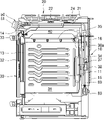
도 1은 본 발명의 일 실시예에 따른 조리기기를 도시한 사시도이고, 도 2는 도 1에 도시된 조리기기를 도시한 정면도이며, 도 3은 도 1에 도시된 조리기기의 내부 구성을 보여주는 측단면도이다.1 is a perspective view showing a cooking appliance according to an embodiment of the present invention, FIG. 2 is a front view showing the cooking appliance shown in FIG. 1, and FIG. 3 is an internal configuration of the cooking appliance shown in FIG. It is a side cross-sectional view.
도 1 내지 도 4를 참조하면, 본 발명의 일 실시예에 따른 조리기기는 쿡탑부(20)와 오븐부(30)를 포함할 수 있다.1 to 4 , a cooking appliance according to an embodiment of the present invention may include a
조리기기(1)는 본체(10)에 의해 외관이 형성될 수 있다. 본체(10)는, 대략 직육면체 형상을 포함하는 형태로 마련될 수 있으며, 그 내부공간에 설치되는 다수의 부품을 보호하기 위하여 소정의 강도를 갖는 재질로 형성될 수 있다.The
상기 본체(10)는, 본체(10)의 골격을 형성하는 캐비티(11), 및 캐비티(11)의 전방에 배치되어 본체(10)의 전면을 형성하는 프런트 패널(13)을 포함하여 이루어질 수 있다. 캐비티(11)의 내부에는 조리실(31)이 형성되며, 프런트 패널(13)의 내부에는 조리실(31)을 전방으로 개방하는 개구부가 형성될 수 있다.The
본체(10)의 상부에는, 쿡탑부(20)가 배치될 수 있다. 쿡탑부(20)는, 개방된 공간 즉, 상측에 놓이는 음식물 또는 음식물이 담긴 용기를 가열하여 음식물을 요리할 수 있게 마련될 수 있다. 쿡탑부(20)에는, 쿡탑부(20)의 상면 외관을 형성하면서 본체(10)의 상단을 폐쇄하는 탑플레이트(21)가 제공될 수 있다.A
쿡탑부(20)에는, 요리하고자 하는 음식물 또는 음식물이 담긴 용기를 가열하기 위한 적어도 하나 이상의 쿡탑가열부(22)가 배치될 수 있다.At least one
일례로서, 쿡탑가열부(22)는, 가스연료를 이용하는 가열장치로 구비될 수 있다. 다른 예로서, 쿡탑가열부는 전기를 이용하는 히터나 유도가열부로 구비될 수도 있다. 이처럼, 이용되는 열원의 종류에 따라 쿡탑가열부(22)의 구조는 변경될 수 있다.As an example, the
그리고 쿡탑부(20)의 하부에는, 오븐부(30)가 배치될 수 있다. 오븐부(30)의 내부공간에는, 음식물이 요리되는 공간을 제공하는 조리실(31)이 마련될 수 있다.In addition, the
캐비티(11)는 전면이 개방된 육면체의 형태로 형성될 수 있으며, 조리실(31)은 이러한 캐비티(11)의 내부에 형성될 수 있다. 즉 조리실(31)은, 캐비티(11) 내부에 배치된 대략 육면체 형상의 공간으로 형성될 수 있으며, 전방으로 개방된 공간으로 형성될 수 있다.The
이러한 조리실(31)이 차폐된 상태에서, 조리실(31) 내부가 가열되면서 음식물 조리가 이루어질 수 있다. 즉 오븐부(30)에서는, 조리실(31)이 실질적으로 음식물이 요리되는 공간이다.In a state in which the
조리기기에는, 조리실(31)을 가열하는 가열부가 마련될 수 있다. 이러한 가열부는, 가스연료를 이용하는 가열장치로 구비될 수 있다. 다른 예로서, 쿡탑가열부는 전기를 이용하는 히터로 구비될 수도 있다. 이처럼, 이용되는 열원의 종류에 따라 가열부의 구조는 변경될 수 있다.A heating unit for heating the
본 실시예에서는, 가열부가 가스연료를 이용하는 가열장치로 구비되는 것으로 예시된다. 이에 따르면, 조리실(31)의 상측에는 상기 조리실(31)의 내부공간을 상측에서 가열하는 브로일 버너(35)가 제공될 수 있고, 조리실(31)의 하측에도 조리실(31)의 내부공간을 하측에서 가열하는 베이커 버너 형태의 버너가 더 제공될 수도 있다.In this embodiment, it is exemplified that the heating unit is provided as a heating device using gas fuel. According to this, a
또한 조리실(31)의 후측에는, 뜨거운 공기를 대류시켜 조리실(31)의 내부공간을 가열하는 컨벡션부(37)가 더 제공될 수 있다.In addition, a
컨벡션부(37)는, 조리실(31) 내부공간의 공기를 강제로 유동시킨다. 즉 컨벡션부(37)는, 조리실(31) 내부공간의 공기를 흡입하여 가열한 후, 조리실(31)의 내부 공간으로 배출시키면서 공기를 유동시킴으로써, 조리실(31)의 내부공간이 가열되도록 하고, 이로써 조리실(31)의 내부공간에 위치하는 음식물이 균일하게 가열되도록 한다.The
오븐부(30)에는, 조리실(31)을 선택적으로 개폐하는 도어(32)가 회동 가능하게 제공될 수 있다. 일례로서, 도어(32)는 그 하단을 중심으로 상단이 상하로 회동하는 풀-다운(Pull-down) 방식으로 조리실(31)을 개폐하는 형태로 제공될 수 있다.A
이러한 도어(32)는, 전체적으로 소정의 두께를 가지는 육면체 형태로 형성될 수 있다. 이러한 도어(32)의 전방에는, 손잡이(33)가 배치될 수 있다. 손잡이(33)는, 사용자가 도어(32)를 회동시키고자 할 때 파지할 수 있게 마련된다. 사용자는, 손잡이(33)를 이용하여 도어(32)를 용이하게 회동시킬 수 있다.The
조리기기의 전면 상부, 즉 캐비티(11)의 상부 전면에는 컨트롤패널(50)이 구비될 수 있다. 컨트롤패널(50)은, 조리기기 전면 외관의 일부를 형성할 수 있다. 이러한 컨트롤패널(50)에는, 조리기기의 동작을 조절하기 위한 노브(51) 및 조리기기의 작동 상태를 표시하는 디스플레이(52) 등이 구비될 수 있다.The
예컨대, 컨트롤패널(50)은 도어(32)의 상부 및 쿡탑부(20)의 전방에 배치되는 컨트롤패널 커버(50a)에 입력부(51) 및 디스플레이(52)가 설치된 형태로 구비될 수 있다.For example, the
입력부(52)에는 다수의 조작스위치가 마련되며, 이를 통해 사용자가 직접 조작신호를 입력할 수 있다. 이때 조작스위치는 회전 조작 가능한 노브(Knob) 형태로 마련될 수도 있고, 누름 조작이나 터치 조작 가능한 버튼 또는 패널 형태로 마련될 수도 있다.The
또한 컨트롤패널(50)에는, 조리기기의 동작 정보 또는 음식물의 요리 정보 등을 제공하는 디스플레이(52)가 더 마련될 수 있다. 사용자는, 디스플레이(52)를 통해 조리기기에 관한 다양한 정보를 확인할 수 있다.In addition, the
다른 예로서, 디스플레이(52)가 터치 조작 가능한 터치 패널 형태로 마련되고, 이로써 하나의 터치 패널에 입력부(51)와 디스플레이(52)가 함께 구성될 수도 있다.As another example, the
한편, 조리실(31)의 후방에는, 배후공간(34)이 마련될 수 있다. 배후공간(34)은, 캐비티(11)의 후방에 배치되며, 조리실(31)과 배후공간(34) 사이를 전후방향으로 구획하는 구획면(30a)에 의해 조리실(31)과 구획된 공간이다. 배후공간(34)의 전방 경계면은 구획면(30a)에 의해 정의되고, 배후공간(34)의 후방 경계면은 캐비티(11)의 후방에 설치되는 리어 커버(15)에 의해 정의될 수 있다.Meanwhile, a
캐비티(11)의 외부에는, 상부공간(40)이 마련될 수 있다. 상부공간(40)은, 캐비티(11)의 상부 및 컨트롤패널(50)의 배후에 배치될 수 있다. 상부공간(40)의 내부에는, 쿡탑가열부(22)를 구성하기 위한 부품이나 전장부품들이 설치되기 위한 공간이 형성될 수 있다.An
상부공간(40)의 전면은, 프런트 패널(13)에 의해 차폐될 수 있다. 프런트 패널(13)은, 캐비티(11)와 도어(32) 사이에 배치될 수 있다. 이러한 프런트 패널(13)은, 적어도 일부분이 상부공간(40)의 전방을 가로막게 배치될 수 있다. 예컨대, 조리실(31)의 상부에 배치된 프런트 패널(13)의 상부 영역이 상부공간(40)의 전면을 차폐할 수 있다.The front surface of the
프런트 패널(13)에는, 흡기구(14)가 마련될 수 있다. 흡기구(14)는, 프런트 패널(13)에 전후방향으로 관통되게 형성될 수 있다. 이러한 흡기구(14)는, 상부공간(40) 외부의 공기가 상부공간(40) 내부로 유입되기 위한 통로를 프런트 패널(13) 상에 형성할 수 있다.The
[쿡탑부의 구조][Structure of the cooktop part]
쿡탑부(20)는, 상술한 바와 같이, 오븐부(30)의 상부에 배치되며, 탑플레이트(21) 및 쿡탑가열부(22)를 포함할 수 있다.As described above, the
탑플레이트(21)는 캐비티(11)의 상부에 배치되며, 상부공간(40)은 탑플레이트(21)와 캐비티(11) 사이에 배치될 수 있다. 즉 탑플레이트(21)는, 탑플레이트(21)와 캐비티(11) 사이에 상부공간(40)이 형성되도록, 캐비티(11)의 상부를 덮을 수 있다.The
캐비티(11)의 외부에는, 상부공간(40)이 마련될 수 있다. 상부공간(40)은, 캐비티(11)와 탑플레이트(21) 사이에 배치되되, 컨트롤패널(50)의 배후에 배치될 수 있다. 상부공간(40)의 내부에는, 쿡탑가열부(22)를 구성하기 위한 부품이나 전장부품들이 설치되기 위한 공간이 형성될 수 있다.An
예컨대, 쿡탑가열부(22)가 가스연료를 이용하는 가열장치로 구비되는 경우, 상부공간(40)에는 가스를 연소시키는 버너, 버너에 가스를 공급하기 위한 공급관, 버너로의 가스 공급을 조절하기 위한 밸브 등이 배치될 수 있다.For example, when the
다른 예로서, 쿡탑가열부(22)가 전기를 이용하는 가열장치로 구비되는 경우, 상부공간(40)에는 히터나 유도가열부, 그리고 이들을 구동시키기 위한 각종 전장부품들이 배치될 수 있다.As another example, when the
본체(10)는, 사이드 패널(17)을 더 포함할 수 있다. 사이드 패널(17)은, 캐비티(11)의 양측부에 각각 배치될 수 있다. 각각의 사이드 패널(17)은, 캐비티(11)의 외측에서 캐비티(11)의 측부를 덮으며 본체(10)의 측방 외관을 형성할 수 있다.The
각각의 사이드 패널(17)은, 캐비티(11)의 측부를 덮으며 캐비티(11)의 상부로 연장되게 형성될 수 있다. 이에 따라 상부공간(40)의 측방 경계면은, 캐비티(11)의 양측에서 상부로 연장되는 한 쌍의 사이드 패널(17)에 의해 정의될 수 있다.Each
캐비티(11)의 후방에는 리어 커버(15)가 배치될 수 있다. 리어 커버(15)는, 캐비티(11)의 후방을 덮으며 본체(10)의 후방 외관을 형성할 수 있다. 이러한 리어 커버(15)는, 캐비티(11)의 후방에 마련되는 배후공간(34)의 후방 경계면을 정의할 수 있다.A
또한 리어 커버(15)에는 환기구(16)가 마련될 수 있다. 환기구(16)는, 리어 커버(15)에 전후방향으로 관통되게 형성될 수 있으며, 배후공간(34) 내부에 배치된 전장부품의 냉각을 위한 공기 출입 통로를 리어 커버(15) 상에 형성할 수 있다.In addition, a
상기 리어 커버(15)는, 캐비티(11)의 후방을 덮으며 캐비티(11)의 상부로 연장되게 형성될 수 있다. 이에 따라 상부공간(40)의 후방 경계면은, 캐비티(11)의 후방에서 상부로 연장되는 리어 커버(15)에 의해 정의될 수 있다.The
즉 상부공간(40)의 전후방 및 양측방은 프런트 패널(13)과 리어 커버(15) 및 한 쌍의 사이드 패널(17)에 의해 둘러싸이며, 탑플레이트(21)는 이러한 상부공간(40)의 상부를 덮는다.That is, the front and rear and both sides of the
이러한 탑플레이트(21)는, 프런트 패널(13)과 리어 커버(15) 및 한 쌍의 사이드 패널(17)의 상부에 배치되며, 프런트 패널(13)과 리어 커버(15) 및 한 쌍의 사이드 패널(17)과 각각 결합될 수 있다. 즉 탑플레이트(21)는, 프런트 패널(13)과 리어 커버(15) 및 한 쌍의 사이드 패널(17)과 각각 결합되면서, 상부공간(40)의 상부에 고정될 수 있다.The
[조리기기의 연료 공급 구조][Fuel supply structure of cooking equipment]
본 실시예의 조리기기(1)는, 가스공급부를 더 포함할 수 있다. 가스공급부는, 오븐부(30)에 마련된 가열부와 쿡탑부(20)에 마련된 쿡탑가열부(22) 중 적어도 어느 하나에 가스를 공급하도록 마련된다.The
가스공급부는, 본체(10)의 외부, 좀 더 구체적으로는 조리실(31)의 외부에 위치하도록 캐비티(11)의 후방에 배치될 수 있다. 본 실시예에서는, 가스공급부가 배후공간(34)에 배치되는 것으로 예시된다. 이러한 가스공급부는, 제1메인파이프(60) 및 제1밸브(65)를 포함하여 이루어질 수 있다.The gas supply unit may be disposed at the rear of the
제1메인파이프(60)는, 조리기기(1) 외부의 가스공급원으로부터 공급되는 가스를 조리기기(1)에 마련된 가열부로 공급하기 위해 마련될 수 있다. 그리고 제1밸브(65)는, 제1메인파이프(60)에 의해 형성된 유로를 개폐할 수 있게 마련된다. 이러한 제1밸브(65)는, 제1메인파이프(60)를 통해 이루어지는 가스 공급을 단속하도록 마련될 수 있다.The first
아울러 가스공급부는, 거버너(Governor; 70)를 더 포함할 수 있다. 거버너(70)는, 외부의 가스공급원으로부터 제1메인파이프(60)로 공급되는 고압의 가스를 조리기기(1)에 마련된 가열부의 연소에 적합한 수준으로 감압하는 역할을 수행할 수 있다.In addition, the gas supply unit may further include a governor (Governor; 70). The governor 70 may serve to reduce the high-pressure gas supplied to the first
거버너(70)를 통해 제1메인파이프(60)로 공급된 가스는, 제1메인파이프(60)와 연결된 조리기기(1)의 각 가열부로 공급될 수 있다. 예컨대, 조리실(31)의 상측에 배치된 브로일 버너(35) 및 조리실(31)의 후측에 배치되는 컨벡션부(37)에 마련되는 컨벡션 버너에 제1메인파이프(60)가 연결될 수 있다. 이에 따라 거버너(70)를 통해 제1메인파이프(60)로 공급된 가스는, 제1메인파이프(60)를 통해 브로일 버너(35)와 컨벡션부(37)의 컨벡션 버너에 공급될 수 있다.The gas supplied to the first
브로일 버너(35)와 제1메인파이프(60) 사이, 컨벡션 버너와 제1메인파이프 사이에는 가스공급관이 각각 마련될 수 있다. 가스공급관은, 브로일 버너(35)와 제1메인파이프(60) 사이, 컨벡션 버너와 제1메인파이프(60) 사이를 각각 연결할 수 있다. 제1메인파이프(60)의 가스는, 가스공급관을 통해 브로일 버너(35)와 컨벡션 버너로 각각 공급될 수 있다.A gas supply pipe may be provided between the
제1메인파이프(60)는, 제2메인파이프(23)와 연결될 수 있다. 이에 따라, 제1메인파이프(60)로 공급된 가스는, 제2메인파이프(23)로 공급될 수 있다. 제2메인파이프(23)로 공급된 가스는, 쿡탑가열부(22)의 연소에 필요한 연료로 공급될 수 있다.The first
본 실시예에서는, 쿡탑가열부(22)가 가스연료를 이용하는 가열장치로 구비되는 것으로 예시된다. 이러한 쿡탑가열부(22)는, 상부공간(40)에 배치되는 버너(22)와 버너파이프(25) 등을 포함할 수 있다.In this embodiment, it is exemplified that the
버너(22)는 가스를 연소시켜 화염을 발생시키며, 쿡탑부(20)는 이 화염을 이용하여 음식물을 조리할 수 있다. 제2메인파이프(23)와 버너(22) 사이는 버너파이프(25)에 의해 연결되며, 제2메인파이프(23)의 가스가 버너파이프(25)를 통해 버너(22)로 공급될 수 있다.The
쿡탑부(20)에는 복수개의 버너(22)가 구비될 수 있으며, 제2메인파이프(23)와 복수개의 버너(22) 사이가 버너파이프(25; 도 6 참조)에 의해 각각 연결될 수 있다. 제2메인파이프(23)와 복수개의 버너파이프(25) 사이에는 매니폴드(26; 도 6 참조)가 마련될 수 있다. 매니폴드(26)는, 제2메인파이프(23)로부터 분기되어 제2메인파이프와 복수개의 버너파이프(25) 사이를 연결할 수 있다.A plurality of
아울러 쿡탑부(20)에는 제2밸브(27; 도 6 참조)가 마련될 수 있다. 제2밸브(27)는, 버너파이프(25)로부터 버너(22)로의 연료 공급을 조절할 수 있다. 이러한 제2밸브(27)는, 각각의 버너(22)나 그와 연결된 버너파이프(25)에 각각 설치되어 각 버너(22)로의 연료 공급을 각각 조절할 수 있다.In addition, a second valve 27 (refer to FIG. 6 ) may be provided in the
[서브어셈블리의 구조][Structure of sub-assembly]
도 4는 도 1에 도시된 조리기기에서의 쿡탑부 및 컨트롤패널 분리 상태를 도시한 분해 사시도이고, 도 5는 도 1에 도시된 조리기기에서의 쿡탑부 분리 상태를 도시한 측단면도이며, 도 6은 도 5에 도시된 서브어셈블리를 확대하여 도시한 확대도이다.4 is an exploded perspective view illustrating a state in which the cooktop unit and the control panel are separated from the cooking appliance shown in FIG. 1 , and FIG. 6 is an enlarged view illustrating the subassembly shown in FIG. 5 .
도 4 내지 도 6을 참조하면, 쿡탑부(20)는 서브어셈블리(100)에 의해 형성될 수 있다. 서브어셈블리(100)는, 쿡탑부(20)를 구성하는 각 부품들이 일체화된 하나의 조립체 형태로 제공될 수 있다. 이러한 서브어셈블리(100)는, 탑플레이트(21)와 버너(22)와 제2메인파이프(23) 등을 포함하여 이루어질 수 있다.4 to 6 , the
일례로서, 서브어셈블리(100)는 탑플레이트(21)와 버너(22)와 제2메인파이프(23)의 조합으로 형성될 수 있으며, 오븐부(30)와 분리된 독립된 조립체 형태로 마련될 수 있다. 서브어셈블리(100)에서는, 적어도 하나의 버너(22)가 탑플레이트(21)에 결합되고, 이 버너(22)와 연결된 제2메인파이프(23)가 버너(22)와의 결합을 매개로 탑플레이트(21)의 하부에 고정될 수 있다.As an example, the
아울러 서브어셈블리(100)는, 버너파이프(25)와 매니폴드(26) 및 제2밸브(27)를 더 포함할 수 있다. 서브어셈블리(100)에서는, 적어도 하나의 버너(22)가 버너파이프(25)와 각각 연결되고, 이 버너파이프(25)는 매니폴드(26)를 매개로 제2메인파이프(23)와 연결될 수 있다. 그리고 제2밸브(27)는 버너(22)나 그와 연결된 버너파이프(25) 또는 매니폴드(26)에 각각 설치될 수 있다.In addition, the
즉 서브어셈블리(100)에서는, 탑플레이트(21)에 결합된 적어도 하나의 버너(22)에 버너파이프(25)가 각각 연결되고, 제2메인파이프(23)가 매니폴드(26)를 매개로 하나 이상의 버너파이프(25)와 연결될 수 있다.That is, in the
이러한 서브어셈블리(100)는, 탑플레이트(21)에 결합된 적어도 하나의 버너(22), 및 이 버너(22)에 연결됨으로써 버너(22)와 함께 탑플레이트(21)에 고정되는 버너파이프(25)와 매니폴드(26)와 제2밸브(27) 및 제2메인파이프(23)가 하나의 조립체를 구성하는 형태로 제공될 수 있다.This
이러한 서브어셈블리(100)에서, 제2메인파이프(23)는 제1메인파이프(60)와 분리된 상태로 탑플레이트(21)의 하부에 고정될 수 있다. 이러한 제2메인파이프(23)는, 가로관부(23a)와 세로관부(23b)를 포함할 수 있다.In this
가로관부(23a)는, 탑플레이트(21)의 하부에서 탑플레이트(21)와 나란한 방향으로 연장될 수 있다. 본 실시예에서는, 가로관부(23a)가 전후방향으로 연장되는 것으로 예시된다. 이러한 가로관부(23a)의 일측, 예컨대 가로관부(23a)의 전방 단부는, 매니폴드(26)와 연결되며 탑플레이트(21)의 하부에 고정될 수 있다. 그리고 가로관부(23a)의 타측, 예컨대 가로관부(23a)의 후방 단부는, 세로관부(23b)와 연결될 수 있다.The
세로관부(23b)는, 가로관부(23a)의 후방 단부로부터 하부방향으로 연장될 수 있다. 가로관부(23a)와 세로관부(23b)의 내부에는 가스의 유동이 이루어지기 위한 유로가 형성되며, 가로관부(23a) 내부의 유로와 세로관부(23b) 내부의 유로가 서로 연결될 수 있다. 이에 따라 제1메인파이프(60)를 통해 공급되는 가스는, 제1메인파이프(60)와 연결된 세로관부(23b) 및 이와 연결된 가로관부(23a)를 통해 버너(22) 측으로 공급될 수 있다.The
제1메인파이프(60)와 세로관부(23b) 사이에는, 제1연결부(60a) 및 제2연결부(23c)가 마련될 수 있다. 제1연결부(60a)는 제1메인파이프(60)에 마련되며, 제2연결부(23c)는 제2메인파이프(23)에 마련될 수 있다.A
본 실시예에 따르면, 제1메인파이프(60)는 캐비티(11)의 후방에서 상부방향으로 연장된다. 즉 제1메인파이프(60)는, 거버너(70)로부터 상부방향으로 연장되는 형태로 구비될 수 있다. 제1연결부(60a)는, 이러한 제1메인파이프(60)의 상측 단부에 배치될 수 있다. 그리고 세로관부(23b)는, 제1메인파이프(60)와 나란한 방향, 즉 하부방향으로 연장된다. 제2연결부(23c)는, 이러한 세로관부(23b)의 하측 단부에 배치될 수 있다.According to this embodiment, the first
제1연결부(60a)와 제2연결부(23c)는, 서로 상하방향으로 배치된 상태에서 상하방향으로 결합될 수 있다. 즉 하부의 제1연결부(60a)와 상부의 제2연결부(23c)가 상하방향으로 결합되고, 이러한 제1연결부(60a)와 제2연결부(23c) 간의 결합에 의해 제1메인파이프(60)와 세로관부(23b)가 서로 연결될 수 있다.The
일례로서, 제1연결부(60a)와 제2연결부(23c)가 상하방향으로 끼움 결합되는 방식으로 제1연결부(60a)와 제2연결부(23c) 간의 연결이 이루어질 수 있다. 다른 예로서, 제1연결부(60a)와 제2연결부(23c)는 상하방향의 끼움 결합과 나사 결합이 함께 이루어지는 방식으로 연결될 수도 있다.As an example, the connection between the
상기한 바와 같이, 서브어셈블리(100)는 탑플레이트(21), 버너(22), 버너파이프(25), 매니폴드(26), 제2밸브(27) 및 제2메인파이프(23) 등과 같이 쿡탑부(20)를 구성하는 대부분의 부품들이 일체화된 하나의 조립체 형태로 제공될 수 있다.As described above, the
이러한 서브어셈블리(100)는, 서브어셈블리(100)만으로도 쿡탑부(20)의 구성이 가능하도록 마련될 수 있으며, 오븐부(30)와 분리된 독립적인 단위체로 제작될 수 있다.The sub-assembly 100 may be provided so that the
[쿡탑부 설치 구조][Cook top part installation structure]
도 7은 도 5에 도시된 조리기기에서의 쿡탑부 조립 상태를 도시한 측단면도이고, 도 8은 조리기기의 다른 예를 도시한 분해 사시도이다.7 is a side cross-sectional view illustrating an assembly state of the cooktop unit in the cooking appliance shown in FIG. 5 , and FIG. 8 is an exploded perspective view illustrating another example of the cooking appliance.
도 6 및 도 7을 참조하면, 본 실시예의 조리기기(1)는 크게 오븐부(30)와 쿡탑부(20)로 구분될 수 있다. 조리기기(1)의 조립 공정에서는, 오븐부(30)의 조립이 먼저 이루어진 후, 쿡탑부(20)의 조립이 마지막에 이루어질 수 있다. 즉 오븐부(30)의 조립이 먼저 이루어진 상태에서, 그 위에 쿡탑부(20)가 얹혀지는 형태로 조리기기(1)의 조립이 이루어질 수 있다.6 and 7 , the
제1메인파이프(60)는, 본체(10)의 외부, 좀 더 구체적으로는 조리실(31)의 외부에 위치하도록 캐비티(11)의 후방에 배치될 수 있다. 본 실시예에서는, 제1메인파이프(60)가 배후공간(34)에 배치되는 것으로 예시된다.The first
상기 제1메인파이프(60)는, 배후공간(34)에 배치되며, 거버너(70)로부터 상부방향으로 연장되는 형태로 마련될 수 있다. 그리고 제1연결부(60a)는, 제1메인파이프(60)의 상측 단부에 마련될 수 있다.The first
쿡탑부(20)의 조립은, 제2메인파이프(23)가 제1메인파이프(60)와 연결되며 서브어셈블리(100)가 오븐부(30)의 상부에 결합되는 형태로 이루어질 수 있다.The
상기한 바와 같이, 제1메인파이프(60)는 조리실(31)보다 후방에 배치되고, 제2메인파이프(23)는 탑플레이트(21)의 하부에서 제1메인파이프(60)와 연결될 수 있다. 제1메인파이프(60)는, 오븐부(30)에 고정된 형태로 제공될 수 있다. 그리고 제2메인파이프(23)는, 쿡탑부(20), 바꾸어 말하면 서브어셈블리(100)에 고정된 형태로 제공될 수 있다.As described above, the first
서브어셈블리(100)는, 캐비티(11)를 상부에서 덮으며 쿡탑부(20)를 형성할 수 있다. 그리고 제1메인파이프(60)와 제2메인파이프(23)가 상하"?항으?* 연결되면서, 쿡탑부(20)로의 연료 공급을 위한 제1메인파이프(60)와 쿡탑부(20) 간의 연결이 이루어질 수 있다.The
쿡탑부(20)의 설치는, 서브어셈블리(100)에 구비된 탑플레이트(21)를 오븐부(30)의 상부에 얹으며 오븐부(30)와 결합시킴으로써 이루어질 수 있다. 예컨대, 탑플레이트(21)는, 프런트 패널(13)과 리어 커버(15) 및 한 쌍의 사이드 패널(17)의 상부에 배치되며, 프런트 패널(13)과 리어 커버(15) 및 한 쌍의 사이드 패널(17)과 각각 결합될 수 있다. 즉 탑플레이트(21)는, 프런트 패널(13)과 리어 커버(15) 및 한 쌍의 사이드 패널(17)과 각각 결합되면서, 상부공간(40)의 상부에 고정될 수 있다.The
이와 같이 탑플레이트(21)가 오븐부(30)의 상부에 결합됨에 따라, 서브어셈블리(100)가 오븐부(30)의 상부에 고정될 수 있다. 그리고 이와 같이 서브어셈블리(100)가 오븐부(30)의 상부에 고정됨에 따라, 서브어셈블리(100)에 마련된 버너(22), 버너파이프(25), 매니폴드(26), 제2밸브(27), 제2메인파이프(23) 등과 같은 부품들이 오븐부(30)의 상부에 고정되면서, 쿡탑부(20)의 설치가 이루어지게 된다.As described above, as the
즉 서브어셈블리(100)를 오븐부(30)의 상부에 조립하는 작업만으로, 오븐부(30)의 상부에 쿡탑부(20)를 설치하는 쿡탑부(20) 조립 작업이 완료될 수 있게 된다. 이로써, 조립 라인에서의 쿡탑부(20) 조립 작업이 매우 쉽고 신속하게 이루어질 수 있게 된다.That is, only by assembling the
상기와 같이 서브어셈블리(100)를 오븐부(30)의 상부에 조립하는 단순하고 쉬운 작업만으로 가스레인지 형태의 쿡탑부(20)의 설치가 이루어질 수 있다면, 하나의 라인에서 여러 종류의 조리기기(1)를 제조하는데 유리한 환경이 조성될 수 있다.As described above, if the gas range
도 8에 도시된 바와 같이, 전기레인지 형태의 쿡탑부(20a)를 갖는 조리기기(1a)를 조립하는 조립 라인에서는, 미리 제작된 전기레인지 형태의 쿡탑부(20a)가 조립 공정 중 마지막 공정에서 오븐부(30)의 상부에 얹혀지며 조리기기(1a)의 조립이 완료될 수 있다.As shown in FIG. 8 , in an assembly line for assembling a
이와 같은 조리기기(1a)를 조립하던 조립 라인에서, 도 5 내지 도 7에 도시된 바와 같은 본 실시예의 서브어셈블리(100)에 의해 형성되는 가스레인지 형태의 쿡탑부(20)를 갖는 조리기기(1)를 조립하게 되더라도, 조립 라인의 공수 및 투입 인원에 별다른 변동이 없게 된다.In the assembly line for assembling the
미리 제작된 전기레인지 형태의 쿡탑부(20a)를 오븐부(30)의 상부에 조립하는 것과 마찬가지로, 미리 제작된 서브어셈블리(100)를 오븐부(30)의 상부에 조립하는 것만으로 쿡탑부(20)의 설치가 완료될 수 있기 때문이다.Similarly to assembling the pre-fabricated electric range-
이로써 하나의 조립 라인에서 가스레인지를 구비하는 조리기기(1)의 조립과 전기레인지를 구비하는 조리기기(1a)의 조립이 모두 효율적으로 이루어질 수 있게 된다.Accordingly, both the assembling of the
또한 가스레인지를 구비하는 조리기기(1)를 조립 중이던 조립 라인에서 다른 종류의 조리기기(예컨대, 전기레인지를 구비하는 조리기기)를 조립하거나 그 반대의 경우에도 해당 조립 라인의 생산 효율이 효과적으로 유지될 수 있게 된다.In addition, the production efficiency of the assembly line is effectively maintained even in the case of assembling other types of cooking devices (eg, cooking devices having an electric range) on the assembly line in which the
만약 오븐부(30)가 가스 오븐 형태로 제조된 상태라면, 이 가스 오븐 형태의 오븐부(30)의 상부에 서브어셈블리(100)를 조립하여 가스 오븐 + 가스레인지 형태의 조리기기(1)를 제작할 수 있다.If the
또한 동일한 라인에서, 가스 오븐 형태의 오븐부(30)의 상부에 서브어셈블리(100) 대신에 전기레인지 형태의 쿡탑부(20a)가 조립된다면, 가스 오븐 + 전기레인지 형태의 조리기기(1a)가 제작될 수 있다.Also, in the same line, if the
다른 예로서, 오븐부(30)가 전기 오븐 형태로 제조된 상태라면, 이 전기븐 형태의 오븐부(30)의 상부에 서브어셈블리(100)를 조립하여 전기오븐 + 가스레인지 형태의 조리기기를 제작할 수 있다.As another example, if the
또한 동일한 라인에서, 가스 오븐 형태의 오븐부(30)의 상부에 서브어셈블리(100) 대신에 전기레인지 형태의 쿡탑부(20a)가 조립된다면, 전기 오븐 + 전기레인지 형태의 조리기기가 제작될 수 있다.Also, in the same line, if the
즉 상기와 같이 가스레인지 형태의 쿡탑부(20)와 전기레인지 형태의 쿡탑부(20a)가 모두 단순하고 쉬운 조립 작업만으로 설치될 수 있으므로, 하나의 조립 라인에서 다양한 형태의 조리기기에 대한 조립 작업이 효과적으로 이루어질 수 있으면서도, 그 과정에서 조립 라인의 생산 효율이 효과적으로 유지되는 효과가 제공될 수 있게 된다.That is, as described above, since the
다른 예로서, 서브어셈블리(100)는 컨트롤패널(50)을 더 포함하는 형태로 마련될 수 있다. 이에 따르면, 서브어셈블리(100)는 탑플레이트(21), 버너(22), 버너파이프(25), 매니폴드(26), 제2밸브(27) 및 제2메인파이프(23) 등과 같이 쿡탑부(20)를 구성하는 대부분의 부품들과 컨트롤패널(50)을 구성하는 대부분의 부품들이 일체화된 하나의 조립체 형태로 제공될 수 있다.As another example, the
이 경우, 컨트롤패널(50)은 탑플레이트(21)의 전방에서 탑플레이트(21)와 결합되면서 쿡탑부(20)를 구성하는 다른 부품들과 함께 서브어셈블리(100)를 형성할 수 있다. 이에 따라, 서브어셈블리(100)는 그 자체만으로 쿡탑부(20) 및 컨트롤패널(50)의 구성이 가능하도록 마련될 수 있으며, 오븐부(30)와 분리된 독립적인 단위체로 제작될 수 있다.In this case, the
이처럼 제작되는 서브어셈블리(100)는, 오븐부(30)의 상부에 서브어셈블리(100)를 얹어 조립하는 쉽고 단순한 조립 작업만으로 쿡탑부(20) 및 컨트롤패널(50)의 설치가 완료되도록 함으로써, 조리기기(1) 조립 라인의 생산 효율이 더욱 향상될 수 있도록 하는 효과를 제공할 수 있다.The sub-assembly 100 produced in this way, by placing the sub-assembly 100 on the upper part of the
본 발명은 도면에 도시된 실시예를 참고로 하여 설명되었으나, 이는 예시적인 것에 불과하며, 당해 기술이 속하는 분야에서 통상의 지식을 가진 자라면 이로부터 다양한 변형 및 균등한 타 실시예가 가능하다는 점을 이해할 것이다. 따라서, 본 발명의 진정한 기술적 보호범위는 아래의 특허청구범위에 의해서 정하여져야 할 것이다.Although the present invention has been described with reference to the embodiment shown in the drawings, this is merely exemplary, and those of ordinary skill in the art to which various modifications and equivalent other embodiments are possible. will understand Accordingly, the true technical protection scope of the present invention should be defined by the following claims.
1 : 조리기기
10 : 본체
11 : 캐비티
13 : 프런트 패널
14 : 흡기구
15 : 리어 커버
16 : 환기구
17 : 사이드 패널
20 : 쿡탑부
21 : 탑플레이트
22 : 쿡탑가열부
23 : 제2메인파이프
23a : 가로관부
23b : 세로관부
23c : 제2연결부
25 : 버너파이프
26 : 매니폴드
27 : 제2밸브
30: 오븐부
30a : 구획면
31 : 조리실
32 : 도어
33 : 핸들
34 : 배후공간
35 : 브로일 버너
37 : 컨벡션부
38 : 컨벡션 모터
40 : 상부공간
50 : 컨트롤패널
51 : 입력부
52 : 디스플레이
60 : 제1메인파이프
60a : 제1연결부
65 : 제1밸브
70 : 거버너
100 : 서브어셈블리1: Cooking equipment
10: body
11: cavity
13: front panel
14: intake port
15: rear cover
16: ventilation hole
17: side panel
20: cooktop unit
21: top plate
22: cooktop heating unit
23: second main pipe
23a: transverse pipe part
23b: vertical tube part
23c: second connection part
25: burner pipe
26: Manifold
27: second valve
30: oven unit
30a: compartment plane
31 : kitchen
32 : door
33 : handle
34: back space
35 : Broil Burner
37: convection unit
38: convection motor
40: upper space
50: control panel
51: input unit
52: display
60: first main pipe
60a: first connection part
65: first valve
70 : governor
100: subassembly
Claims (10)
상기 오븐부에 설치되어 연료 공급을 위한 유로를 형성하는 제1메인파이프;
상기 오븐부의 상부에 배치되어 상기 제1메인파이프와 연결되는 쿡탑부;를 포함하고, 상기 쿡탑부는,
상기 캐비티와의 사이에 상부공간이 형성되도록 상기 캐비티의 상부를 덮는 탑플레이트;
적어도 일부분이 상기 상부공간에 배치되는 버너; 및
상기 제1메인파이프와 상기 버너 사이를 연결하는 제2메인파이프;를 포함하고,
상기 제1메인파이프는 상기 오븐부에 고정되며, 상기 제2메인파이프는 상기 쿡탑부에 고정되고,
상기 제1메인파이프와 상기 제2메인파이프가 분리 가능하게 연결되는 조리기기.
an oven unit including a cavity in which a cooking chamber is formed;
a first main pipe installed in the oven unit to form a flow path for supplying fuel;
and a cooktop unit disposed on the oven unit and connected to the first main pipe, wherein the cooktop unit comprises:
a top plate covering an upper portion of the cavity to form an upper space therebetween;
a burner, at least a portion of which is disposed in the upper space; and
Including; and a second main pipe connecting the first main pipe and the burner.
The first main pipe is fixed to the oven unit, the second main pipe is fixed to the cooktop unit,
A cooking appliance in which the first main pipe and the second main pipe are detachably connected.
상기 탑플레이트와, 상기 탑플레이트에 결합되는 적어도 하나의 상기 버너, 및 상기 버너와 연결되는 제2메인파이프의 조합으로 서브어셈블리가 형성되고,
상기 오븐부와 분리된 상태의 상기 서브어셈블리에서, 상기 탑플레이트와 상기 버너 및 상기 제2메인파이프가 상기 오븐부와 분리되며 상기 제2메인파이프가 상기 제1메인파이프와 분리된 상태로 상기 탑플레이트와 상기 버너 및 상기 제2메인파이프가 하나의 조립체를 형성하는 조리기기.
According to claim 1,
A subassembly is formed by a combination of the top plate, at least one burner coupled to the top plate, and a second main pipe coupled to the burner,
In the subassembly separated from the oven unit, the top plate, the burner, and the second main pipe are separated from the oven unit, and the second main pipe is separated from the first main pipe. A cooking appliance in which a plate, the burner, and the second main pipe form a single assembly.
상기 제2메인파이프가 상기 제1메인파이프와 연결되며 상기 서브어셈블리가 상기 오븐부의 상부에 결합되어 상기 오븐부의 상부에 상기 쿡탑부가 형성되는 조리기기.
3. The method of claim 2,
The second main pipe is connected to the first main pipe and the subassembly is coupled to an upper portion of the oven unit to form the cooktop unit on the oven unit.
상기 제1메인파이프는, 상기 조리실보다 후방에 배치되고,
상기 제2메인파이프는, 상기 탑플레이트의 하부에서 상기 제1메인파이프와 연결되는 조리기기.
3. The method of claim 2,
The first main pipe is disposed behind the cooking chamber,
The second main pipe is a cooking appliance connected to the first main pipe under the top plate.
상기 제1메인파이프는, 상기 캐비티의 후방에서 상부방향으로 연장되고,
상기 서브어셈블리는, 상기 캐비티를 상부에서 덮으며 상기 쿡탑부를 형성하고,
상기 제1메인파이프와 상기 제2메인파이프가 상하방향으로 연결되는 조리기기.
5. The method of claim 4,
The first main pipe extends upwardly from the rear of the cavity,
The subassembly covers the cavity from an upper portion and forms the cooktop part,
A cooking appliance in which the first main pipe and the second main pipe are connected in a vertical direction.
상기 탑플레이트의 하부에서 전후방향으로 연장되는 가로관부;
상기 가로관부의 후방 단부로부터 하부방향으로 연장되는 세로관부; 및
상기 세로관부의 단부에 마련되어 상기 제1메인파이프와 상기 제2메인파이프를 연결시키는 연결부;를 포함하는 조리기기.
According to claim 5, The second main pipe,
a transverse pipe portion extending in the front-rear direction from the lower portion of the top plate;
a vertical tube portion extending downwardly from the rear end of the horizontal tube portion; and
and a connection part provided at an end of the vertical tube part to connect the first main pipe and the second main pipe.
상기 세로관부와 상기 제1메인파이프가 일렬로 연결되는 조리기기.
7. The method of claim 6,
A cooking appliance in which the vertical tube portion and the first main pipe are connected in a line.
상기 제2메인파이프와 상기 버너 사이를 연결하는 적어도 하나의 버너파이프;
상기 제2메인파이프로부터 분기되어 상기 제2메인파이프와 상기 버너파이프 사이를 연결하는 매니폴드;
상기 버너파이프로부터 상기 버너로의 연료 공급을 조절하는 밸브;를 더 포함하고,
상기 버너파이프와 상기 매니폴드 및 상기 밸브가 상기 탑플레이트에 직간접적으로 고정되는 조리기기.
The method of claim 2, wherein the cooktop unit,
at least one burner pipe connecting the second main pipe and the burner;
a manifold branching from the second main pipe and connecting the second main pipe and the burner pipe;
Further comprising; a valve for controlling the fuel supply from the burner pipe to the burner,
A cooking appliance in which the burner pipe, the manifold, and the valve are directly or indirectly fixed to the top plate.
상기 탑플레이트와, 적어도 하나의 상기 버너와, 상기 제2메인파이프와, 상기 버너파이프와, 상기 매니폴드, 및 상기 밸브의 조합으로 상기 서브어셈블리가 형성되고,
상기 오븐부와 분리된 상태의 상기 서브어셈블리에서, 상기 탑플레이트와 상기 버너와 상기 제2메인파이프가 상기 버너파이프와 상기 매니폴드 및 상기 밸브가 상기 오븐부와 분리된 상태로 하나의 조립체를 형성하는 조리기기.
9. The method of claim 8,
the subassembly is formed by a combination of the top plate, the at least one burner, the second main pipe, the burner pipe, the manifold, and the valve;
In the subassembly separated from the oven unit, one assembly is formed with the top plate, the burner, and the second main pipe separated from the burner pipe, the manifold, and the valve from the oven unit. cooking equipment.
상기 쿡탑플레이트의 전방에 배치되어 상기 쿡탑가열부의 동작을 조절하는 조작부를 구비하는 컨트롤패널을 더 포함하고,
상기 컨트롤패널이 상기 쿡탑부와 결합되며 상기 컨트롤패널과 상기 쿡탑부의 조합으로 상기 서브어셈블리가 형성되는 조리기기.3. The method of claim 2,
Further comprising a control panel disposed in front of the cooktop plate and having a manipulation unit for controlling the operation of the cooktop heating unit,
The control panel is coupled to the cooktop unit, and the subassembly is formed by a combination of the control panel and the cooktop unit.
Priority Applications (1)
| Application Number | Priority Date | Filing Date | Title |
|---|---|---|---|
| KR1020210039250A KR20220134078A (en) | 2021-03-26 | 2021-03-26 | Cooking appliance |
Applications Claiming Priority (1)
| Application Number | Priority Date | Filing Date | Title |
|---|---|---|---|
| KR1020210039250A KR20220134078A (en) | 2021-03-26 | 2021-03-26 | Cooking appliance |
Publications (1)
| Publication Number | Publication Date |
|---|---|
| KR20220134078A true KR20220134078A (en) | 2022-10-05 |
Family
ID=83596862
Family Applications (1)
| Application Number | Title | Priority Date | Filing Date |
|---|---|---|---|
| KR1020210039250A KR20220134078A (en) | 2021-03-26 | 2021-03-26 | Cooking appliance |
Country Status (1)
| Country | Link |
|---|---|
| KR (1) | KR20220134078A (en) |
Citations (1)
| Publication number | Priority date | Publication date | Assignee | Title |
|---|---|---|---|---|
| US8402962B2 (en) | 2003-12-29 | 2013-03-26 | Lg Electronics Inc. | Apparatus for supply mixed gas for gas burners of radiant heating type |
-
2021
- 2021-03-26 KR KR1020210039250A patent/KR20220134078A/en active Search and Examination
Patent Citations (1)
| Publication number | Priority date | Publication date | Assignee | Title |
|---|---|---|---|---|
| US8402962B2 (en) | 2003-12-29 | 2013-03-26 | Lg Electronics Inc. | Apparatus for supply mixed gas for gas burners of radiant heating type |
Similar Documents
| Publication | Publication Date | Title |
|---|---|---|
| US5909533A (en) | Electric cooking oven with infrared gas broiler | |
| KR101904660B1 (en) | Cooking appliance | |
| KR20120119842A (en) | Cooker | |
| CA2475035C (en) | Combination radiant/convection gas cooking appliance | |
| KR100688360B1 (en) | Apparatus for ventilation in a radiation gas range | |
| US11421894B2 (en) | Spill guard for a gas oven burner | |
| KR101864491B1 (en) | Burner and cooking appliance therewith | |
| US10571131B2 (en) | Oven appliance having a convection assembly | |
| US11125447B2 (en) | Cooking apparatus | |
| KR101824736B1 (en) | A burner and cooker comprising the same | |
| KR20220134078A (en) | Cooking appliance | |
| KR101064849B1 (en) | Reflecter and gas oven range comprising the same | |
| EP3666139A1 (en) | Assembly comprising a gas oven and an oven for cooking steaks | |
| US20220268449A1 (en) | Cooking appliance | |
| KR20220101532A (en) | Cooking appliance | |
| WO2020244529A1 (en) | Oven device combining radiation grilling and convection grilling | |
| CN217978936U (en) | Electric and gas dual-purpose combined stove | |
| KR102067271B1 (en) | Cooking appliance | |
| US20220079387A1 (en) | Cooking apparatus | |
| US20220221158A1 (en) | Cooking appliance | |
| KR100565693B1 (en) | Gas oven range of radiant heating type | |
| KR101751059B1 (en) | Built-in type gas oven range | |
| KR101067949B1 (en) | Reflecter and gas oven range comprising the same | |
| KR20240003611A (en) | Ignition device and cooking appliance therewith | |
| KR101690329B1 (en) | Cooking appliance |
Legal Events
| Date | Code | Title | Description |
|---|---|---|---|
| A201 | Request for examination |