KR20220133241A - Drag-and-lift-based wind turbine system with adjustable blades - Google Patents
Drag-and-lift-based wind turbine system with adjustable blades Download PDFInfo
- Publication number
- KR20220133241A KR20220133241A KR1020227029263A KR20227029263A KR20220133241A KR 20220133241 A KR20220133241 A KR 20220133241A KR 1020227029263 A KR1020227029263 A KR 1020227029263A KR 20227029263 A KR20227029263 A KR 20227029263A KR 20220133241 A KR20220133241 A KR 20220133241A
- Authority
- KR
- South Korea
- Prior art keywords
- blade
- wind
- arrangement
- blade panel
- sub
- Prior art date
Links
- 238000012545 processing Methods 0.000 claims abstract description 26
- 230000000712 assembly Effects 0.000 claims abstract description 20
- 238000000429 assembly Methods 0.000 claims abstract description 20
- 230000000903 blocking effect Effects 0.000 claims abstract description 4
- 230000007246 mechanism Effects 0.000 claims description 20
- 238000000034 method Methods 0.000 claims description 14
- 230000006378 damage Effects 0.000 claims description 13
- 230000033001 locomotion Effects 0.000 claims description 8
- 239000000463 material Substances 0.000 claims description 7
- 230000003287 optical effect Effects 0.000 claims description 4
- 230000002441 reversible effect Effects 0.000 claims description 4
- 239000000956 alloy Substances 0.000 claims description 3
- 229910045601 alloy Inorganic materials 0.000 claims description 3
- 239000000919 ceramic Substances 0.000 claims description 3
- 239000000835 fiber Substances 0.000 claims description 3
- 239000011521 glass Substances 0.000 claims description 3
- 239000002184 metal Substances 0.000 claims description 3
- 229910052751 metal Inorganic materials 0.000 claims description 3
- 229910052755 nonmetal Inorganic materials 0.000 claims description 3
- 229920000642 polymer Polymers 0.000 claims description 3
- 230000005855 radiation Effects 0.000 claims description 3
- 239000002023 wood Substances 0.000 claims description 3
- 230000005484 gravity Effects 0.000 claims description 2
- 230000000694 effects Effects 0.000 claims 1
- 230000008713 feedback mechanism Effects 0.000 claims 1
- 238000013461 design Methods 0.000 description 22
- 230000015654 memory Effects 0.000 description 12
- 230000008859 change Effects 0.000 description 7
- 230000008901 benefit Effects 0.000 description 4
- 230000006870 function Effects 0.000 description 4
- 239000000654 additive Substances 0.000 description 3
- 230000007423 decrease Effects 0.000 description 3
- 230000005611 electricity Effects 0.000 description 3
- 238000004519 manufacturing process Methods 0.000 description 3
- 238000012986 modification Methods 0.000 description 3
- 230000004048 modification Effects 0.000 description 3
- 230000008569 process Effects 0.000 description 3
- 230000005355 Hall effect Effects 0.000 description 2
- 229910000831 Steel Inorganic materials 0.000 description 2
- 230000000996 additive effect Effects 0.000 description 2
- 230000005540 biological transmission Effects 0.000 description 2
- 238000006243 chemical reaction Methods 0.000 description 2
- 238000007654 immersion Methods 0.000 description 2
- 230000000670 limiting effect Effects 0.000 description 2
- 238000005457 optimization Methods 0.000 description 2
- 230000036961 partial effect Effects 0.000 description 2
- 239000010959 steel Substances 0.000 description 2
- 238000003860 storage Methods 0.000 description 2
- 230000002159 abnormal effect Effects 0.000 description 1
- 230000002411 adverse Effects 0.000 description 1
- 230000003466 anti-cipated effect Effects 0.000 description 1
- 238000013459 approach Methods 0.000 description 1
- 238000003491 array Methods 0.000 description 1
- 238000007664 blowing Methods 0.000 description 1
- 238000004140 cleaning Methods 0.000 description 1
- 230000000295 complement effect Effects 0.000 description 1
- 230000002950 deficient Effects 0.000 description 1
- 238000010586 diagram Methods 0.000 description 1
- 230000009977 dual effect Effects 0.000 description 1
- 238000005516 engineering process Methods 0.000 description 1
- 230000007613 environmental effect Effects 0.000 description 1
- 238000003306 harvesting Methods 0.000 description 1
- 238000009434 installation Methods 0.000 description 1
- 230000002452 interceptive effect Effects 0.000 description 1
- 238000012423 maintenance Methods 0.000 description 1
- 230000007257 malfunction Effects 0.000 description 1
- 230000005404 monopole Effects 0.000 description 1
- 230000002093 peripheral effect Effects 0.000 description 1
- 238000010248 power generation Methods 0.000 description 1
- 239000003380 propellant Substances 0.000 description 1
- 230000002829 reductive effect Effects 0.000 description 1
- 230000004044 response Effects 0.000 description 1
- 230000001360 synchronised effect Effects 0.000 description 1
- 238000012546 transfer Methods 0.000 description 1
- 238000013024 troubleshooting Methods 0.000 description 1
Images


Classifications
-
- F—MECHANICAL ENGINEERING; LIGHTING; HEATING; WEAPONS; BLASTING
- F03—MACHINES OR ENGINES FOR LIQUIDS; WIND, SPRING, OR WEIGHT MOTORS; PRODUCING MECHANICAL POWER OR A REACTIVE PROPULSIVE THRUST, NOT OTHERWISE PROVIDED FOR
- F03D—WIND MOTORS
- F03D3/00—Wind motors with rotation axis substantially perpendicular to the air flow entering the rotor
- F03D3/06—Rotors
- F03D3/062—Rotors characterised by their construction elements
-
- F—MECHANICAL ENGINEERING; LIGHTING; HEATING; WEAPONS; BLASTING
- F03—MACHINES OR ENGINES FOR LIQUIDS; WIND, SPRING, OR WEIGHT MOTORS; PRODUCING MECHANICAL POWER OR A REACTIVE PROPULSIVE THRUST, NOT OTHERWISE PROVIDED FOR
- F03D—WIND MOTORS
- F03D3/00—Wind motors with rotation axis substantially perpendicular to the air flow entering the rotor
- F03D3/06—Rotors
- F03D3/062—Rotors characterised by their construction elements
- F03D3/066—Rotors characterised by their construction elements the wind engaging parts being movable relative to the rotor
- F03D3/067—Cyclic movements
- F03D3/068—Cyclic movements mechanically controlled by the rotor structure
-
- F—MECHANICAL ENGINEERING; LIGHTING; HEATING; WEAPONS; BLASTING
- F03—MACHINES OR ENGINES FOR LIQUIDS; WIND, SPRING, OR WEIGHT MOTORS; PRODUCING MECHANICAL POWER OR A REACTIVE PROPULSIVE THRUST, NOT OTHERWISE PROVIDED FOR
- F03D—WIND MOTORS
- F03D3/00—Wind motors with rotation axis substantially perpendicular to the air flow entering the rotor
- F03D3/02—Wind motors with rotation axis substantially perpendicular to the air flow entering the rotor having a plurality of rotors
-
- F—MECHANICAL ENGINEERING; LIGHTING; HEATING; WEAPONS; BLASTING
- F03—MACHINES OR ENGINES FOR LIQUIDS; WIND, SPRING, OR WEIGHT MOTORS; PRODUCING MECHANICAL POWER OR A REACTIVE PROPULSIVE THRUST, NOT OTHERWISE PROVIDED FOR
- F03D—WIND MOTORS
- F03D7/00—Controlling wind motors
- F03D7/06—Controlling wind motors the wind motors having rotation axis substantially perpendicular to the air flow entering the rotor
- F03D7/065—Controlling wind motors the wind motors having rotation axis substantially perpendicular to the air flow entering the rotor controlling rotor speed
-
- F—MECHANICAL ENGINEERING; LIGHTING; HEATING; WEAPONS; BLASTING
- F03—MACHINES OR ENGINES FOR LIQUIDS; WIND, SPRING, OR WEIGHT MOTORS; PRODUCING MECHANICAL POWER OR A REACTIVE PROPULSIVE THRUST, NOT OTHERWISE PROVIDED FOR
- F03D—WIND MOTORS
- F03D1/00—Wind motors with rotation axis substantially parallel to the air flow entering the rotor
- F03D1/06—Rotors
- F03D1/065—Rotors characterised by their construction elements
- F03D1/0675—Rotors characterised by their construction elements of the blades
-
- F—MECHANICAL ENGINEERING; LIGHTING; HEATING; WEAPONS; BLASTING
- F03—MACHINES OR ENGINES FOR LIQUIDS; WIND, SPRING, OR WEIGHT MOTORS; PRODUCING MECHANICAL POWER OR A REACTIVE PROPULSIVE THRUST, NOT OTHERWISE PROVIDED FOR
- F03D—WIND MOTORS
- F03D3/00—Wind motors with rotation axis substantially perpendicular to the air flow entering the rotor
- F03D3/06—Rotors
- F03D3/062—Rotors characterised by their construction elements
- F03D3/064—Fixing wind engaging parts to rest of rotor
-
- F—MECHANICAL ENGINEERING; LIGHTING; HEATING; WEAPONS; BLASTING
- F03—MACHINES OR ENGINES FOR LIQUIDS; WIND, SPRING, OR WEIGHT MOTORS; PRODUCING MECHANICAL POWER OR A REACTIVE PROPULSIVE THRUST, NOT OTHERWISE PROVIDED FOR
- F03D—WIND MOTORS
- F03D3/00—Wind motors with rotation axis substantially perpendicular to the air flow entering the rotor
- F03D3/06—Rotors
- F03D3/062—Rotors characterised by their construction elements
- F03D3/066—Rotors characterised by their construction elements the wind engaging parts being movable relative to the rotor
- F03D3/067—Cyclic movements
-
- F—MECHANICAL ENGINEERING; LIGHTING; HEATING; WEAPONS; BLASTING
- F03—MACHINES OR ENGINES FOR LIQUIDS; WIND, SPRING, OR WEIGHT MOTORS; PRODUCING MECHANICAL POWER OR A REACTIVE PROPULSIVE THRUST, NOT OTHERWISE PROVIDED FOR
- F03D—WIND MOTORS
- F03D7/00—Controlling wind motors
- F03D7/02—Controlling wind motors the wind motors having rotation axis substantially parallel to the air flow entering the rotor
- F03D7/0204—Controlling wind motors the wind motors having rotation axis substantially parallel to the air flow entering the rotor for orientation in relation to wind direction
- F03D7/0208—Orientating out of wind
- F03D7/0212—Orientating out of wind the rotating axis remaining horizontal
-
- F—MECHANICAL ENGINEERING; LIGHTING; HEATING; WEAPONS; BLASTING
- F03—MACHINES OR ENGINES FOR LIQUIDS; WIND, SPRING, OR WEIGHT MOTORS; PRODUCING MECHANICAL POWER OR A REACTIVE PROPULSIVE THRUST, NOT OTHERWISE PROVIDED FOR
- F03D—WIND MOTORS
- F03D7/00—Controlling wind motors
- F03D7/02—Controlling wind motors the wind motors having rotation axis substantially parallel to the air flow entering the rotor
- F03D7/0204—Controlling wind motors the wind motors having rotation axis substantially parallel to the air flow entering the rotor for orientation in relation to wind direction
- F03D7/0208—Orientating out of wind
- F03D7/0216—Orientating out of wind the rotating axis changing to vertical position
-
- F—MECHANICAL ENGINEERING; LIGHTING; HEATING; WEAPONS; BLASTING
- F03—MACHINES OR ENGINES FOR LIQUIDS; WIND, SPRING, OR WEIGHT MOTORS; PRODUCING MECHANICAL POWER OR A REACTIVE PROPULSIVE THRUST, NOT OTHERWISE PROVIDED FOR
- F03D—WIND MOTORS
- F03D7/00—Controlling wind motors
- F03D7/02—Controlling wind motors the wind motors having rotation axis substantially parallel to the air flow entering the rotor
- F03D7/028—Controlling wind motors the wind motors having rotation axis substantially parallel to the air flow entering the rotor controlling wind motor output power
-
- F—MECHANICAL ENGINEERING; LIGHTING; HEATING; WEAPONS; BLASTING
- F03—MACHINES OR ENGINES FOR LIQUIDS; WIND, SPRING, OR WEIGHT MOTORS; PRODUCING MECHANICAL POWER OR A REACTIVE PROPULSIVE THRUST, NOT OTHERWISE PROVIDED FOR
- F03D—WIND MOTORS
- F03D7/00—Controlling wind motors
- F03D7/02—Controlling wind motors the wind motors having rotation axis substantially parallel to the air flow entering the rotor
- F03D7/04—Automatic control; Regulation
- F03D7/042—Automatic control; Regulation by means of an electrical or electronic controller
- F03D7/043—Automatic control; Regulation by means of an electrical or electronic controller characterised by the type of control logic
- F03D7/044—Automatic control; Regulation by means of an electrical or electronic controller characterised by the type of control logic with PID control
-
- F—MECHANICAL ENGINEERING; LIGHTING; HEATING; WEAPONS; BLASTING
- F03—MACHINES OR ENGINES FOR LIQUIDS; WIND, SPRING, OR WEIGHT MOTORS; PRODUCING MECHANICAL POWER OR A REACTIVE PROPULSIVE THRUST, NOT OTHERWISE PROVIDED FOR
- F03D—WIND MOTORS
- F03D7/00—Controlling wind motors
- F03D7/02—Controlling wind motors the wind motors having rotation axis substantially parallel to the air flow entering the rotor
- F03D7/04—Automatic control; Regulation
- F03D7/042—Automatic control; Regulation by means of an electrical or electronic controller
- F03D7/048—Automatic control; Regulation by means of an electrical or electronic controller controlling wind farms
-
- F—MECHANICAL ENGINEERING; LIGHTING; HEATING; WEAPONS; BLASTING
- F05—INDEXING SCHEMES RELATING TO ENGINES OR PUMPS IN VARIOUS SUBCLASSES OF CLASSES F01-F04
- F05B—INDEXING SCHEME RELATING TO WIND, SPRING, WEIGHT, INERTIA OR LIKE MOTORS, TO MACHINES OR ENGINES FOR LIQUIDS COVERED BY SUBCLASSES F03B, F03D AND F03G
- F05B2240/00—Components
- F05B2240/20—Rotors
- F05B2240/21—Rotors for wind turbines
- F05B2240/211—Rotors for wind turbines with vertical axis
-
- F—MECHANICAL ENGINEERING; LIGHTING; HEATING; WEAPONS; BLASTING
- F05—INDEXING SCHEMES RELATING TO ENGINES OR PUMPS IN VARIOUS SUBCLASSES OF CLASSES F01-F04
- F05B—INDEXING SCHEME RELATING TO WIND, SPRING, WEIGHT, INERTIA OR LIKE MOTORS, TO MACHINES OR ENGINES FOR LIQUIDS COVERED BY SUBCLASSES F03B, F03D AND F03G
- F05B2240/00—Components
- F05B2240/20—Rotors
- F05B2240/30—Characteristics of rotor blades, i.e. of any element transforming dynamic fluid energy to or from rotational energy and being attached to a rotor
- F05B2240/31—Characteristics of rotor blades, i.e. of any element transforming dynamic fluid energy to or from rotational energy and being attached to a rotor of changeable form or shape
- F05B2240/313—Characteristics of rotor blades, i.e. of any element transforming dynamic fluid energy to or from rotational energy and being attached to a rotor of changeable form or shape with adjustable flow intercepting area
-
- Y—GENERAL TAGGING OF NEW TECHNOLOGICAL DEVELOPMENTS; GENERAL TAGGING OF CROSS-SECTIONAL TECHNOLOGIES SPANNING OVER SEVERAL SECTIONS OF THE IPC; TECHNICAL SUBJECTS COVERED BY FORMER USPC CROSS-REFERENCE ART COLLECTIONS [XRACs] AND DIGESTS
- Y02—TECHNOLOGIES OR APPLICATIONS FOR MITIGATION OR ADAPTATION AGAINST CLIMATE CHANGE
- Y02B—CLIMATE CHANGE MITIGATION TECHNOLOGIES RELATED TO BUILDINGS, e.g. HOUSING, HOUSE APPLIANCES OR RELATED END-USER APPLICATIONS
- Y02B10/00—Integration of renewable energy sources in buildings
- Y02B10/30—Wind power
-
- Y—GENERAL TAGGING OF NEW TECHNOLOGICAL DEVELOPMENTS; GENERAL TAGGING OF CROSS-SECTIONAL TECHNOLOGIES SPANNING OVER SEVERAL SECTIONS OF THE IPC; TECHNICAL SUBJECTS COVERED BY FORMER USPC CROSS-REFERENCE ART COLLECTIONS [XRACs] AND DIGESTS
- Y02—TECHNOLOGIES OR APPLICATIONS FOR MITIGATION OR ADAPTATION AGAINST CLIMATE CHANGE
- Y02E—REDUCTION OF GREENHOUSE GAS [GHG] EMISSIONS, RELATED TO ENERGY GENERATION, TRANSMISSION OR DISTRIBUTION
- Y02E10/00—Energy generation through renewable energy sources
- Y02E10/70—Wind energy
- Y02E10/72—Wind turbines with rotation axis in wind direction
-
- Y—GENERAL TAGGING OF NEW TECHNOLOGICAL DEVELOPMENTS; GENERAL TAGGING OF CROSS-SECTIONAL TECHNOLOGIES SPANNING OVER SEVERAL SECTIONS OF THE IPC; TECHNICAL SUBJECTS COVERED BY FORMER USPC CROSS-REFERENCE ART COLLECTIONS [XRACs] AND DIGESTS
- Y02—TECHNOLOGIES OR APPLICATIONS FOR MITIGATION OR ADAPTATION AGAINST CLIMATE CHANGE
- Y02E—REDUCTION OF GREENHOUSE GAS [GHG] EMISSIONS, RELATED TO ENERGY GENERATION, TRANSMISSION OR DISTRIBUTION
- Y02E10/00—Energy generation through renewable energy sources
- Y02E10/70—Wind energy
- Y02E10/74—Wind turbines with rotation axis perpendicular to the wind direction
Abstract
조정 가능한 블레이드(blades)를 갖는 드래그 겸 리프트 기반 풍력 터빈 시스템으로서, 시스템은: 베이스 구조 상에 배열된 하나 이상의 출력 구동 로터 - 각 출력 로터는 하나 이상의 1차 제어 배열체(arrangements)를 사용하여 하나 이상의 암(arms)과 연결됨 -; 하나 이상의 암 각각과 회전 가능하게 장착된 하나 이상의 블레이드 패널 어셈블리로서, 각각의 블레이드 패널 어셈블리는: 하나 이상의 암 각각에 회전 가능하게 장착된 보조 회전 샤프트; 하나 이상의 1차 제어 배열체에 의해 제어되는 보조 회전 샤프트와 연결된 장착 배열체 - 각각의 블레이드 패널 장착 배열체는 하나 이상의 2차 제어 배열체를 사용하여 장착 배열체의 하나 이상의 피벗 지점(pivot points)에서 피벗 가능한 하나 이상의 서브-블레이드 패널을 하우징하여, 하나 이상의 서브-블레이드 패널이 회전하는 것을 허용하고, 그로 인해 바람이 블레이드 패널을 부분적으로 또는 완전히 통과하는 것을 차단 및/또는 허용함 - 를 포함하는, 하나 이상의 블레이드 패널 어셈블리; 하나 이상의 처리 모듈, 하나 이상의 1차 제어 배열체 및 하나 이상의 2차 제어 배열체와 연결된 하나 이상의 메인 제어 유닛(Main Control Unit; MCU)과 커플링된, 시스템 제어 매개변수를 판독하기 위한 하나 이상의 센서; 및 하나 이상의 출력 구동 로터의 회전 토크를 하나 이상의 에너지 형태로 변환하도록 구성된 출력 배열체를 포함한다.A drag-cum-lift based wind turbine system having adjustable blades, the system comprising: one or more output drive rotors arranged on a base structure, each output rotor one using one or more primary control arrangements associated with more than one arm -; One or more blade panel assemblies rotatably mounted with each of one or more arms, each blade panel assembly comprising: an auxiliary rotating shaft rotatably mounted on each of the one or more arms; a mounting arrangement coupled with an auxiliary rotating shaft controlled by one or more primary control arrangements, each blade panel mounting arrangement having one or more pivot points of the mounting arrangement using one or more secondary control arrangements housing one or more sub-blade panels that are pivotable in the blade panel, allowing the one or more sub-blade panels to rotate, thereby blocking and/or allowing wind to pass partially or completely through the blade panel; , one or more blade panel assemblies; one or more sensors for reading system control parameters, coupled with one or more main control units (MCUs) coupled with one or more processing modules, one or more primary control arrangements and one or more secondary control arrangements ; and an output arrangement configured to convert rotational torque of the one or more output drive rotors into one or more forms of energy.
Description
본 발명의 실시예는 일반적으로 재생 가능 에너지 생성 시스템 및 장치에 관한 것이다. 특히, 본 개시는 조정 가능한 블레이드를 갖는 드래그 겸 리프트 기반 풍력 터빈 시스템에 관한 것이다.Embodiments of the present invention relate generally to renewable energy generation systems and devices. In particular, the present disclosure relates to a drag-cum-lift based wind turbine system with adjustable blades.
배경 섹션에서 논의된 주제는 단순히 배경 섹션에서 언급된 결과로 선행 기술로 간주되어서는 안 됩니다. 유사하게, 배경 섹션에서 언급되거나 배경 섹션의 주제와 관련된 문제는 선행 기술에서 이전에 인식된 것으로 가정되어서는 안 됩니다. 배경 섹션의 주제는 단지 그 자체로 청구된 기술의 구현에 대응할 수 있는 다른 접근 방식을 나타냅니다.The topics discussed in the Background section should not be considered prior art simply as a result of being mentioned in the Background section. Similarly, issues mentioned in the background section or related to the subject matter of the background section should not be assumed to have been previously recognized in the prior art. The topics in the background section merely represent different approaches that may correspond to the implementation of the claimed technology in its own right.
종종 청정 에너지라고 불리는 재생 에너지는 전 세계적으로 주요 에너지원 중 하나가 되었습니다. 재생 불가능한 자원의 고갈, 오염 증가, 전력에 대한 요구 사항의 증가로 인해 세계는 이제 환경을 해치지 않으면서 에너지 수요를 충족시키기 위해 재생 에너지에 관심을 돌리고 있습니다. 재생 에너지의 가장 인기 있는 두 가지 소스는 태양 에너지와 풍력 에너지입니다. 풍력 터빈과 풍차는 수세기 동안 존재해 왔으며 세계 여러 지역에서 가장 저렴한 에너지원을 제공합니다. Renewable energy, often referred to as clean energy, has become one of the major energy sources worldwide. Due to the depletion of non-renewable resources, increasing pollution and increasing demands on electricity, the world is now turning to renewable energy to meet energy demand without harming the environment. The two most popular sources of renewable energy are solar and wind energy. Wind turbines and windmills have been around for centuries and provide some of the cheapest energy sources in many parts of the world.
모노폴 타워에 수평축 3개 날개가 있는 풍력 터빈이 있는 풍차의 기본 플랫폼 구성은 많이 변경되지 않았습니다. 그러나 풍차 크기는 허브 높이가 6~7배, 로터 직경이 6~8배, 정격 출력이 30~50배 증가했다. 오늘날 풍력 터빈의 크기는 대규모 기념물 및 건물에 필적하는 동시에 터빈 수명 내내 동적이고 복잡한 하중을 견뎌냅니다. 대부분의 풍력 터빈은 관형 강철로 만들어진 타워에 장착된 3개의 블레이드가 장착된 터빈으로 구성됩니다. 두 개의 블레이드가 있거나 콘크리트 또는 강철 격자 타워가 있는 덜 일반적인 품종이 있습니다. 지상 100피트 이상에서 타워는 터빈이 더 높은 고도에서 발견되는 더 빠른 풍속을 활용할 수 있도록 합니다.The basic platform configuration of a windmill with a wind turbine with three horizontal axes on a monopole tower has not changed much. However, the size of the windmill has increased by 6 to 7 times the hub height, 6 to 8 times the rotor diameter, and 30 to 50 times the rated power. Today's wind turbines are comparable in size to large monuments and buildings, while withstanding dynamic and complex loads over the life of the turbine. Most wind turbines consist of a three-blade turbine mounted on a tower made of tubular steel. There are less common varieties with two blades or with concrete or steel lattice towers. Above 100 feet above the ground, the tower allows the turbines to take advantage of the faster wind speeds found at higher altitudes.
과 접촉하는 면적이 전체 면적의 작은 부분을 차지하는 원형 날개와 같은 역할을 하는 프로펠러와 같은 블레이드로 바람의 에너지를 포착합니다. 바람이 불면 블레이드 한쪽에 저기압 공기 주머니가 형성됩니다. 그런 다음 저압 에어 포켓이 블레이드를 쪽으로 잡아당겨 로터가 바람 방향과 직각으로 회전하도록 하며, 이를 리프트라고 합니다. 양력의 힘은 항상 블레이드 전면에 가해지는 바람의 총 힘보다 작으며, 블레이드를 바람의 방향으로 밀려고 하는 힘을 항력이라고 하는 것은 약 300% 이상입니다. 항력을 양력으로 부분적으로 변환하면 로터가 프로펠러처럼 회전합니다. 일련의 기어는 로터의 회전을 분당 약 18회전에서 분당 약 1,500 또는 1,800회전으로 증가시킵니다. 이는 터빈 발전기가 로컬 그리드에 따라 AC 전기를 생산할 수 있게 하는 속도입니다.Wind energy is captured by the propeller-like blades that act like circular blades whose area in contact with them takes up a small fraction of the total area. When the wind blows, a pocket of low pressure air forms on one side of the blade. A pocket of low-pressure air then pulls the blades toward it, causing the rotor to rotate at right angles to the wind direction, known as lift. The force of lift is always less than the total force of the wind on the front of the blade, and the force that pushes the blade in the direction of the wind, called drag, is about 300% or more. Partial conversion of drag into lift causes the rotor to spin like a propeller. A series of gears increases the rotation of the rotor from about 18 revolutions per minute to about 1,500 or 1,800 revolutions per minute. This is the speed at which the turbine generator can produce AC electricity according to the local grid.
유선형 인클로저는 일반적으로 나셀이라고 하는 하우징 내에서 발견되는 기어, 로터 및 발전기를 포함한 주요 터빈 구성요소를 수용합니다. 터빈 타워 꼭대기에 있는 일부 나셀은 헬리콥터가 착륙할 만큼 충분히 큽니다. 확립된 또 다른 핵심 구성요소는 강풍에 의한 손상을 피하기 위해 55mph를 초과하는 바람으로부터 로터 속도를 조절하는 터빈 컨트롤러입니다. 풍속계는 지속적으로 풍속을 측정하고 데이터를 터빈 컨트롤러로 전송합니다. 나셀에 장착된 브레이크도 비상 시 로터를 기계, 전기 또는 유압으로 정지시킵니다.The streamlined enclosure houses the major turbine components, including gears, rotors, and generators, typically found within housings called nacelles. Some nacelles atop the turbine tower are large enough for helicopters to land. Another key component that has been established is the turbine controller, which regulates rotor speed from winds in excess of 55 mph to avoid damage from strong winds. The anemometer continuously measures the wind speed and transmits the data to the turbine controller. Brakes mounted on the nacelle also mechanically, electrically or hydraulically stop the rotor in the event of an emergency.
다가오는 바람의 방향과 다가오는 바람에 대한 블레이드의 피치 사이의 각도를 "받음각"이라고 합니다. 이 받음각이 커질수록 더 많은 양력이 생성되지만 약 20도 이상으로 더 커지면 블레이드가 양력을 감소시키기 시작합니다. 따라서 최적의 토크를 생성하는 로터 블레이드의 이상적인 피치 각도가 있습니다.The angle between the direction of the oncoming wind and the pitch of the blade with respect to the oncoming wind is called the "angle of attack." As this angle of attack increases, more lift is produced, but as it gets bigger, around 20 degrees or more, the blades begin to reduce lift. Therefore, there is an ideal pitch angle of the rotor blades that produces optimal torque.
풍력 터빈 블레이드 디자인과 같은 이 프로펠러는 바람의 양력 에너지만 토크라고 하는 사용 가능한 샤프트 동력으로 변환한다고 말할 수 있습니다. 이것은 바람이 블레이드 위로 미끄러질 때 바람을 늦추거나 감속하여 바람에서 에너지를 추출함으로써 달성됩니다.Like a wind turbine blade design, it can be said that these propellers convert only the wind's lift energy into usable shaft power called torque. This is achieved by extracting energy from the wind by slowing it down or slowing it down as it slides over the blades.
따라서, 블레이드의 더 많은 접촉 면적을 제공하고 낮은 풍속 및 200km/h 이상의 높은 풍속에서도 기능하는 조정 가능한 블레이드를 갖는 드래그 겸 리프트 기반 풍력 터빈 시스템이 필요합니다. 향상된 효율성, 비용 효율성 및 유지 관리가 쉬운 디자인.Therefore, there is a need for a drag-cum-lift based wind turbine system with adjustable blades that provide more contact area of the blades and function even at low wind speeds and high wind speeds of 200 km/h or more. Improved efficiency, cost-effectiveness and easy-to-maintain design.
본 발명의 목적은 블레이드를 바람과 함께 회전시키고 효율을 개선하기 위해 직각이 아닌 회전함으로써 항력 및 양력이 가산되는 조정 가능한 블레이드를 갖는 드래그 겸 양력 기반 풍력 터빈 시스템을 제공하는 것이다.It is an object of the present invention to provide a drag-cum-lift based wind turbine system with adjustable blades in which drag and lift are added by rotating the blades with the wind and non-orthogonal rotation to improve efficiency.
본 발명의 다른 목적은 각 회전 내에서 블레이드의 회전 위치에 응답하여 블레이드의 받음각을 동적으로 변경하여 항력을 주요 추진제로 만들고 양력을 추가하는 것입니다.Another object of the present invention is to dynamically change the angle of attack of the blade in response to the rotational position of the blade within each rotation, making drag the main propellant and adding lift.
초당 5Mtrs 미만에서 초당 80Mtrs 초과로 작동 풍속 범위를 증가시키는 서브-블레이드 패널을 포함하는 블레이드 어셈블리를 제공하는 것이다.It is to provide a blade assembly comprising a sub-blade panel that increases the operating wind speed range from less than 5 Mtrs per second to more than 80 Mtrs per second.
본 발명의 또 다른 목적은 풍력 터빈을 보다 저렴하고 유지 보수가 용이하도록 하는 것이다.Another object of the present invention is to make wind turbines cheaper and easier to maintain.
본 발명의 제1 양태에 따르면, 조정 가능한 블레이드를 갖는 드래그 겸 리프트 기반 풍력 터빈 시스템이 제공된다. 시스템은 베이스 상에 배열된 하나 이상의 출력 구동 로터를 포함하며, 각각의 출력 로터는 하나 이상의 암과 하나 with 이상의 1차 제어 장치에 연결됨; 및 상기 하나 이상의 각각의 암과 회전 가능 하게 연결된 하나 이상의 블레이드 패널 어셈블리 를 포함한다. 각각의 블레이드 패널 어셈블리는 하나 이상의 암 각각으로부터 회전 가능하게 연장되는 보조 회전 샤프트 ; 및 하나 이상의 1차 제어 장치를 통해 보조 회전 샤프트와 연결된 장착 장치를 포함하고, 각각 의 장착 장치 는 하나 이상의 서브 블레이드 패널이 회전하여 바람이 블레이드 패널을 부분적으로 또는 완전히 통과하는 것을 차단 및/또는 허용합니다. 시스템은 하나 이상의 보조 회전 샤프트, 장착 장치, 하나 이상의 서브 블레이드 패널 및 하나 이상의 출력 구동 로터와 결합된 하나 이상의 센서를 더 포함 하고; to collect control information, 주 제어 장치(MCU)는 하나 이상의 센서, 하나 이상의 1차 제어 장치 및 하나 이상의 2차 제어 장치와 연결된 처리 모듈을 가질 수 있습니다. 및 하나 이상의 출력 구동 로터의 회전 토크를 하나 이상의 에너지 형태로 변환하도록 구성된 출력 장치를 포함한다.According to a first aspect of the present invention, there is provided a drag-cum-lift based wind turbine system with adjustable blades. the system includes one or more output drive rotors arranged on a base, each output rotor connected to one or more arms and one or more with one or more primary control devices; and one or more blade panel assemblies rotatably connected to the one or more respective arms. Each blade panel assembly includes an auxiliary rotating shaft rotatably extending from each of the one or more arms; and a mounting device coupled with the auxiliary rotating shaft through one or more primary control devices, each mounting device preventing and/or allowing the one or more sub-blade panels to rotate to partially or completely pass wind through the blade panels; do. the system further comprising one or more sensors coupled to the one or more auxiliary rotating shafts, the mounting device, the one or more sub-blade panels, and the one or more output drive rotors; To collect control information, a main control unit (MCU) may have a processing module associated with one or more sensors, one or more primary control units, and one or more secondary control units. and an output device configured to convert rotational torque of the one or more output drive rotors into one or more forms of energy.
본 발명의 일 실시예에 따르면, MCU는 처리 모듈을 통해 풍향, 풍속, 하나 이상의 출력 구동 로터의 회전 속도, 하나 또는 그 이상의 개별 각도 위치를 동적으로 결정하도록 구성된다. 최대 추력 지점에 대한 더 많은 암 및 하나 이상의 센서를 사용하여 각 장착 장치에 가해지는 힘; 전방 항력 및/또는 양력을 최적화하고 바람에 대한 각 블레이드의 부분 회전 assembly중 역항력 respective.According to an embodiment of the present invention, the MCU is configured to dynamically determine, via the processing module, a wind direction, a wind speed, a rotational speed of one or more output drive rotors, and one or more individual angular positions. force applied to each mounting device using more arms and one or more sensors for the point of maximum thrust; Optimize forward drag and/or lift and reverse drag during partial rotation assembly of each blade against wind, respectively.
본 발명의 실시예에 따르면, 처리 모듈을 통한 MCU는 역항력을 감소시키고 토크를 조절하고 평활화하기 위해 하나 이상의 2차 제어 장치를 사용하여 하나 이상의 서브 블레이드 패널의 개방을 조정하도록 추가로 구성된다. 거센 바람을 차단하고 설계 한계를 초과하는 속도로부터 시스템을 보호하여 중단 없이 안정적이고 최적의 용량 출력을 보장하는 동시에 시스템 손상을 방지합니다.According to an embodiment of the present invention, the MCU through the processing module is further configured to adjust the opening of the one or more sub-blade panels using the one or more secondary control devices to reduce the counter drag and adjust and smooth the torque. It blocks strong winds and protects the system from velocities that exceed design limits, ensuring uninterrupted, reliable and optimal capacity output while preventing system damage.
본 발명의 실시예에 따르면, 하나 이상의 출력 구동 로터는 직렬 또는 병렬 배열로 베이스 상에서 수평으로, 수직으로 또는 그 사이에서 비스듬히 배열될 수 있다.According to an embodiment of the invention, the one or more output drive rotors may be arranged horizontally, vertically or at an angle between them on the base in a series or parallel arrangement.
본 발명의 실시예에 따르면, 하나 이상의 아암은 하나 이상의 출력 구동 로터 각각 또는 이들의 조합의 양 단부 사이의 섹션 또는 양 단부로부터 반경방향 또는 접선방향으로 연장된다.According to an embodiment of the present invention, one or more arms extend radially or tangentially from either end or a section between opposite ends of each or a combination of one or more output drive rotors.
본 발명의 일 실시예에 따르면, 하나 이상의 서브-블레이드 패널은 수직으로 또는 수평으로 또는 비스듬히 개방되도록 구성되며 with, 하나 이상의 블레이드 패널 어셈블리 의 각각의 장착 배열은 다음과 같다.According to an embodiment of the present invention, the one or more sub-blade panels are configured to open vertically or horizontally or at an angle, with the respective mounting arrangement of the one or more blade panel assemblies as follows.
본 발명의 일 실시예에 따르면, 하나 이상의 서브-블레이드 패널은 금속, non-metal, 합금, 폴리머, 섬유, 유리, ceramic, 목재 또는 이들의 조합으로부터 선택된 재료로 제조된다.According to one embodiment of the present invention, the one or more sub-blade panels are made of a material selected from metal, non-metal, alloy, polymer, fiber, glass, ceramic, wood, or combinations thereof.
본 발명의 일 실시예에 따르면, 하나 이상의 1차 제어 장치 및 2차 제어 장치는 캠 및 종동자 장치, 서보 모터, 벨트 및 풀리 장치, 체인 및 스프로킷 중 하나 이상으로부터 선택되지만 이에 국한되지 않는다. 메커니즘, 기어 장치, 선형 및 회전 액추에이터, 레버 메커니즘, 원심분리기, 유압, 공압 제어, 수치 제어, 스테퍼 모터, 전자기 모터, 전자석, 나사 액추에이터 또는 이들의 조합.According to an embodiment of the present invention, the one or more primary and secondary control devices are selected from, but not limited to, one or more of cam and follower devices, servo motors, belt and pulley devices, chains and sprockets. Mechanisms, gear units, linear and rotary actuators, lever mechanisms, centrifugal, hydraulic, pneumatic controls, numerical controls, stepper motors, electromagnetic motors, electromagnets, screw actuators, or combinations thereof.
본 발명의 실시예에 따르면, 하나 이상의 센서는 방향 센서, 속도 센서, 가속도계, 자이로 센서, 자력계, 방향 센서, 홈 판독기, 돌출 판독기, 광학 판독기, 압력 센서, 방사선 센서를 포함하지만 이에 제한되지는 않습니다. , 천공 디스크 판독기, 자기 센서, 홀 효과 센서, 중력 스위치, 기울기 센서, 인코더, 위치 센서, 회전 속도계, 모션 센서 또는 이들의 조합.According to embodiments of the present invention, one or more sensors include, but are not limited to, orientation sensors, velocity sensors, accelerometers, gyro sensors, magnetometers, orientation sensors, home readers, protrusion readers, optical readers, pressure sensors, radiation sensors. . , perforated disk reader, magnetic sensor, Hall effect sensor, gravity switch, tilt sensor, encoder, position sensor, tachometer, motion sensor or any combination thereof.
본 발명의 제2 양태에 따르면, 풍력 터빈 시스템용 블레이드 패널 조립체가 제공된다. 장착 장치 및 패널 어셈블리는 하나 이상의 1차 제어 장치를 통해 연결된 풍력 터빈 시스템 장착 장치의 하나 이상의 암 각각으로부터 연장되는 보조 회전 샤프트 또는 피봇팅 장치를 포함 한다. 각각의 장착 장치는 하나 이상의 서브 블레이드 n패널이 개별적으로 또는 집합적으로 회전하여 차단 및/ 또는 바람이 블레이드 패널을 부분적으로 또는 완전히 통과하도록 합니다.According to a second aspect of the present invention, a blade panel assembly for a wind turbine system is provided. The mounting device and panel assembly includes an auxiliary rotating shaft or pivoting device extending from each of one or more arms of the wind turbine system mounting device connected via one or more primary control devices. Each mounting device causes one or more sub-blade nPanels to rotate individually or collectively to allow blocking and/or wind to partially or fully pass through the blade panel.
이상에서 인용한 본 발명의 특징이 상세하게 이해될 수 있도록, 위에서 간략히 요약된 본 발명의 설명은 첨부된 도면에 도시된 일부 실시예를 참조하여 가질 수 있다. 그러나, 첨부된 도면은 본 발명의 전형적인 실시예만을 예시하고 따라서 그 범위를 제한하는 것으로 간주되어서는 안 되며, 본 발명은 다른 동등하게 효과적인 실시예를 허용할 수 있음을 주목해야 한다.
걸쳐 유사한 구조를 지칭하는 유사한 참조 번호와 함께 다음의 텍스트 도면을 참조함으로써 명백해질 것이다.
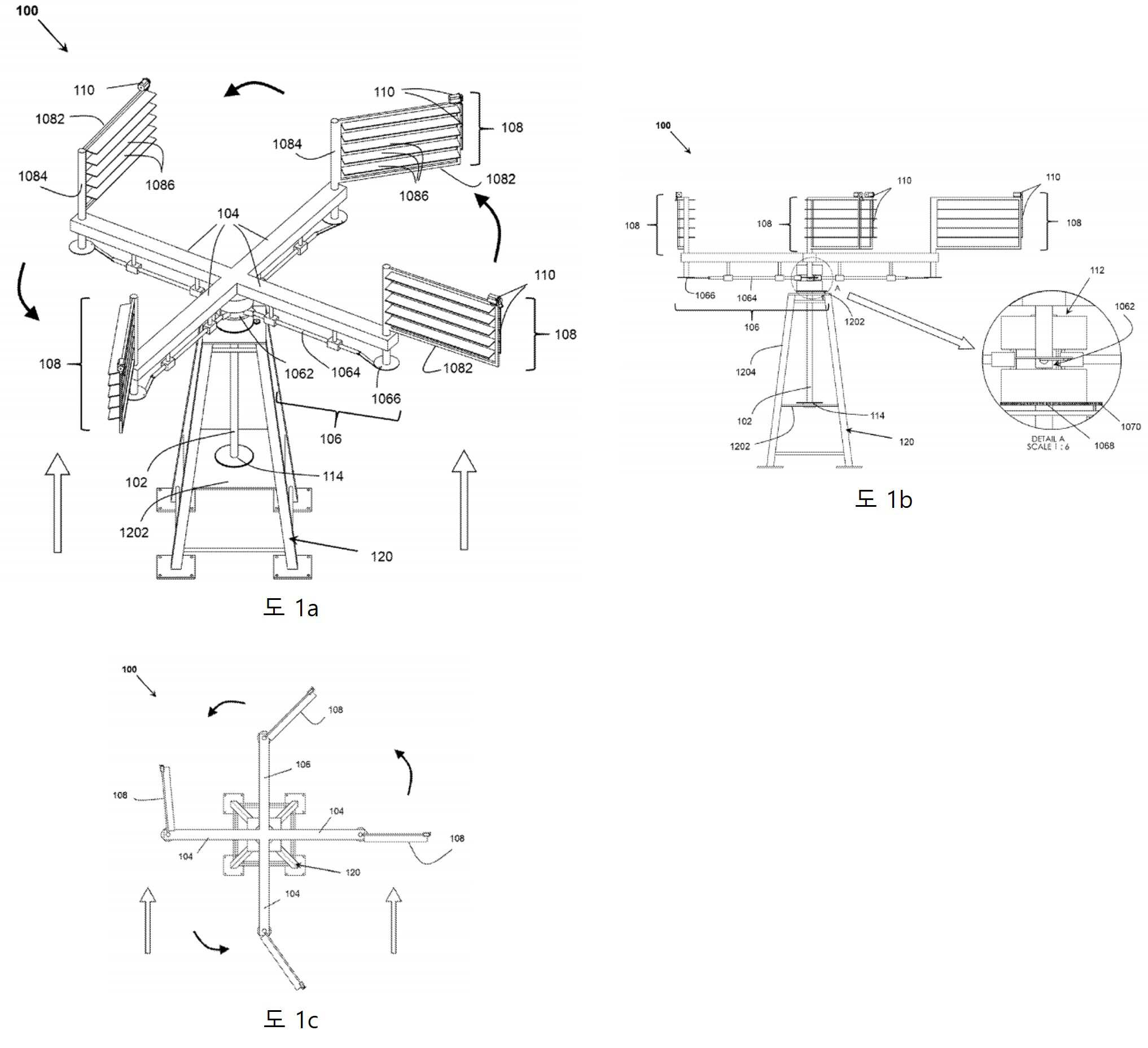
도 1a는 본 발명의 일 실시예에 따른 수직 축 배열의 드래그 컴 리프트 기반 풍력 터빈 시스템의 등각 투영도를 도시한다.
도 1b 내지 도 1c cum lift 는 본 발명의 실시예에 따른 도 1a의 항력 기반 풍력 터빈 시스템의 정면도 및 평면도를 각각 도시한다.
도 2a 내지 도 2c는 본 발명의 일 실시예에 따른, 시스템에서 메인 제어 유닛(MCU)으로서 작용하는 홈 판독기 형태의 캠 및 종동 장치를 도시한 도면.
도 3a 내지 도 3c는 본 발명의 일 실시예에 따른 (a) 폐쇄, (b) 부분 개방/폐쇄 및 (c) 개방 서브 블레이드 패널을 갖는 블레이드 패널 어셈블리를 도시한다.
도 4a cum lift 는 본 발명의 일 실시예에 따른 수평축 배열의 항력 기반 풍력 터빈 시스템의 등각투영도를 도시한다. 그리고
도 4b cum lift 는 본 발명의 일 실시예에 따른, 도 4a의 항력 기반 풍력 터빈 시스템의 측면도를 도시한다.In order that the features of the present invention cited above may be understood in detail, the description of the present invention briefly summarized above may have with reference to some embodiments shown in the accompanying drawings. It should be noted, however, that the accompanying drawings illustrate only typical embodiments of the present invention and are therefore not to be considered limiting of its scope, as the present invention may admit to other equally effective embodiments.
It will become apparent by reference to the following textual drawings with like reference numerals designating like structures throughout.
1A shows an isometric view of a drag com lift based wind turbine system in a vertical axis arrangement according to an embodiment of the present invention.
1b to 1c cum lift show a front view and a top view, respectively, of the drag-based wind turbine system of FIG. 1a according to an embodiment of the present invention;
Figures 2a-2c show a cam and follower in the form of a home reader acting as a main control unit (MCU) in the system, according to an embodiment of the present invention;
3A-3C illustrate a blade panel assembly having (a) closed, (b) partially open/closed and (c) open sub-blade panels in accordance with one embodiment of the present invention.
Figure 4a cum lift shows an isometric view of a drag-based wind turbine system in a horizontal axis arrangement according to an embodiment of the present invention. and
FIG. 4B cum lift shows a side view of the drag-based wind turbine system of FIG. 4A , in accordance with an embodiment of the present invention.
본 발명은 실시예 및 예시적인 도면을 사용하여 예시적으로 설명되지만, 당업자는 본 발명이 설명된 도면 또는 도면의 실시예로 제한되지 않고 다양한 구성요소의 축척을 나타내도록 의도되지 않음을 인식할 것이다.. 또한, 본 발명의 일부를 형성할 수 있는 일부 구성요소는 예시의 용이함을 위해 특정 도면에서 예시되지 않을 수 있으며, 그러한 생략은 어떤 식으로든 개략된 실시예를 제한하지 않는다. 도면 및 그에 대한 상세한 설명은 본 발명을 개시된 특정 형태로 제한하려는 것이 아니라, 반대로, 본 발명은 다음과 같은 본 발명의 범위 내에 속하는 모든 수정, 균등물 및 대안을 포함하는 것으로 이해되어야 한다. 첨부된 청구범위에 의해 정의됩니다. 이 설명 전반에 걸쳐 사용된 "~할 수 있다"라는 단어 는 의무적 의미(즉, 해야 함을 의미)가 아니라 허용적 의미(즉, 잠재적인 의미)로 사용됩니다. 또한, "a" 또는 "an"이라는 단어는 "적어도 하나"를 의미하고 "복수성"이라는 단어는 달리 언급되지 않는 한 "하나 이상"을 의미합니다. 또한, 여기에서 사용된 용어 및 구문은 설명의 목적으로만 사용된 것으로, "포함하는", "포함하는", "갖는", "함유하는" 또는 "포함하는"과 같은 언어 및 이들의 변형은 광범위하고 그 이후에 나열된 주제를 포괄하는 것으로 의도됩니다. 및 인용되지 않은 추가 주제 및 them and 다른 첨가제, 구성 요소, 정수 또는 단계를 배제하기 위한 것이 아닙니다. 마찬가지로 "포함하는"이라는 용어는 적용 가능한 법적 목적에서 "포함하는" 또는 "포함하는"이라는 용어와 동의어로 간주됩니다. 문서, 행위, 재료, 장치, 물품 등은 오로지 본 발명의 맥락을 제공하기 위한 목적으로 명세서에 포함되며, 이러한 사항 중 일부 또는 전부가 선행 기술의 일부를 형성한다고 제안하거나 표현하지 않습니다. b 본 발명과 관련된 분야에서 일반적이거나 일반적인 지식이었다.While the present invention has been illustratively described using embodiments and illustrative drawings, those skilled in the art will recognize that the invention is not limited to the described drawings or embodiments of the drawings and is not intended to scale to various components. .. In addition, some components that may form a part of the present invention may not be illustrated in specific drawings for ease of illustration, and such omission does not limit the outlined embodiment in any way. It is to be understood that the drawings and detailed description thereof are not intended to limit the present invention to the specific form disclosed, but, on the contrary, the present invention includes all modifications, equivalents and alternatives falling within the scope of the present invention as follows. It is defined by the appended claims. The word "may" used throughout this description is used in a permissive sense (ie, a potential meaning), not in the obligatory sense (ie, meaning must). Also, the word "a" or "an" means "at least one" and the word "plurality" means "one or more" unless stated otherwise. Also, the terms and phrases used herein are for descriptive purposes only, and language such as "comprising", "comprising", "having", "containing" or "comprising" and variations thereof It is broad and intended to cover the topics listed thereafter. It is not intended to exclude additional topics and uncited topics and them and other additives, components, integers, or steps. Likewise, the term "comprising" is to be regarded as synonymous with the terms "comprising" or "comprising" for applicable legal purposes. Documents, acts, materials, devices, articles, etc. are included in the specification solely for the purpose of providing the context of the present invention, and it is not suggested or represented that any or all of these matters form part of the prior art. b was common or common knowledge in the field related to the present invention.
본 발명은 첨부된 도면을 참조하여 이하에서 다양한 실시예에 의해 설명되며, 첨부된 도면에서 사용된 참조 번호는 설명 전체를 통하여 유사한 구성요소에 대응한다. 그러나 본 발명은 여러 가지 상이한 형태로 구현될 수 있으며 여기에서 설명하는 실시예에 한정되는 것으로 해석되어서는 안 된다. 오히려, 실시예는 본 개시가 철저하고 완전할 수 있고 본 발명의 범위가 당업자에게 충분히 전달될 수 있도록 제공된다. 다음의 상세한 설명에서, 설명된 구현의 다양한 측면에 대해 숫자 값 및 범위가 제공됩니다. 이러한 값 및 범위는 단지 예로서 취급되어야 하며 청구범위의 범위를 제한하도록 의도되지 않습니다. 또한 구현의 다양한 측면에 적합한 것으로 여러 재료가 식별됩니다. 이들 물질은 예시적인 것으로 취급되어야 하며 본 발명의 범위를 제한하도록 의도되지 않는다. 또한, 여기에 사용된 용어 및 어구는 설명의 목적으로만 사용되며 범위를 제한하는 것으로 해석되어서는 안 됩니다.BRIEF DESCRIPTION OF THE DRAWINGS The present invention is described below by way of various embodiments with reference to the accompanying drawings, wherein reference numerals used in the accompanying drawings correspond to like elements throughout the description. However, the present invention may be embodied in many different forms and should not be construed as being limited to the embodiments described herein. Rather, the examples are provided so that this disclosure will be thorough and complete, and will fully convey the scope of the invention to those skilled in the art. In the detailed description that follows, numerical values and ranges are provided for various aspects of the described implementations. These values and ranges should be treated as examples only and are not intended to limit the scope of the claims. In addition, several materials are identified as suitable for various aspects of implementation. These materials are to be treated as exemplary and are not intended to limit the scope of the present invention. In addition, the terms and phrases used herein are for descriptive purposes only and should not be construed as limiting their scope.
본 발명은 다수의 조정 가능한 블레이드 패널 어셈블리를 갖고 각각의 블레이드 패널 어셈블리 자체가 다수의 제어 가능한(회전 가능한) 서브-블레이드 패널을 포함하는 드래그 겸 리프트 기반 풍력 터빈 시스템을 제공합니다. 새롭고 독창적인 배열을 갖는 본 발명은 전방 항력을 최적화하거나 역항력을 감소시키고 부품 회전 동안 약간의 양력을 생성하기 위해 각 회전 동안 연속적으로 각 블레이드 패널 어셈블리의 입사각을 독립적으로 변경할 수 있습니다. 이 장치는 바람이 메인 로터의 회전에 접선 방향으로 불지 않고 축 방향으로 부는 방식으로 구성됩니다. 메인 로터(들)는 수직, 수평 또는 그 사이의 임의의 각도로 배치될 수 있으며, 각각은 로터 길이의 어느 곳에서나 로터에 연결된 각각의 암에 고정된 하나 이상의 블레이드 패널 어셈블리를 갖는다. 블레이드 패널 어셈블리의 이러한 보조 샤프트는 주 제어 장치 및 제어 장치(예: CAM 장치, 액추에이터 등)에 의해 제어되어 각 회전 주기 동안 지속적으로 변화하는 풍향에 대해 블레이드 패널 의 ,입사각 을 조정합니다. 터빈과 메인 로터의 회전으로부터 에너지를 활용하기 위한 출력 장치가 제공됩니다.The present invention provides a drag and lift based wind turbine system having a plurality of adjustable blade panel assemblies, each blade panel assembly itself comprising a plurality of controllable (rotatable) sub-blade panels. With a novel and unique arrangement, the present invention can independently vary the angle of incidence of each blade panel assembly continuously during each rotation to optimize forward drag or reduce counter drag and generate some lift during component rotation. The device is constructed in such a way that the wind does not blow tangentially to the rotation of the main rotor, but axially. The main rotor(s) may be positioned vertically, horizontally, or at any angle therebetween, each having one or more blade panel assemblies secured to a respective arm connected to the rotor at any point along the length of the rotor. These secondary shafts of the blade panel assembly are controlled by the main control unit and the control unit (eg CAM unit, actuator, etc.) to adjust the angle of incidence of the blade panel for the continuously changing wind direction during each rotation cycle. An output device is provided to utilize energy from the rotation of the turbine and main rotor.
또한, 각 블레이드 패널 어셈블리는 이동 가능하거나 제어 가능한 하위 블레이드 패널을 포함하므로 일반적인 바람/작동 조건에서 하위 블레이드 패널은 공기를 차단하기 위해 닫힌 위치에 있습니다(바람이 치는 최대 영역 제공). 전방 항력 및 양력. 그러나 풍속이 미리 정해진 특정 한계를 초과하기 시작하면 각 블레이드 패널 어셈블리의 서브 블레이드 패널은 독립적으로(부분적으로 또는 완전히) 열리며 과도한 공기가 블레이드 패널을 부분적으로 또는 완전히 통과할 수 있습니다. 이러한 서브 블레이드 패널의 독립적인 제어는 풍속이 30배 이상 변화하더라도 전진 토크를 일정하게 유지하는 데 도움이 됩니다. 이 설계 기능은 과도한 풍속에서 회전을 제어하기 위해 브레이크가 필요하지 않습니다. 이 방법을 사용하면 수집된 회전력을 필요에 따라 다른 형태의 에너지로 추가 변환할 수 있습니다.Additionally, each blade panel assembly includes a movable or controllable sub-blade panel, so under normal wind/operating conditions, the sub-blade panel is in a closed position to block air (providing maximum area of wind). Forward drag and lift. However, when the wind speed begins to exceed certain predetermined limits, the sub-blade panels of each blade panel assembly open independently (partially or fully) and excess air can partially or fully pass through the blade panels. The independent control of these sub-blade panels helps keep the forward torque constant even when wind speed changes by more than 30 times. This design feature eliminates the need for brakes to control rotation at excessive wind speeds. Using this method, the collected torque can be further converted into other forms of energy as needed.
본 발명은 이제 본 발명의 다양한 실시예를 커버하는 도면을 참조하여 설명될 것이다.The invention will now be described with reference to the drawings which cover various embodiments of the invention.
도 1a는 본 발명의 일 실시예에 따른 수직 축 배열의 항력 기반 풍력 터빈 시스템(100)의 등각도를 도시한다. 도 1a에 도시된 바와 같이, 항력 기반 풍력 터빈 시스템(100)(이하 "시스템(100)"이라 함)은 수직 축 배열로 배열된다. 그러나, 본 발명의 시스템(100)은 본 발명 의 범위를 벗어나지 않고 수직축, 수평축, 또는 그 사이의 임의의 위치에 배열될 수 있음을 당업자는 이해할 것이다. 다른 종류의 배열은 또한 설명에서 나중에 설명되는 본 발명 의 다른 실시예에서 논의되었다. 더 나은 설명과 이해의 명확성을 위해, 도 1a 의 시스템(100)의 정면도 및 평면도가 각각 도 1b 내지 도 1c에 도시되어 있다.1A shows an isometric view of a drag-based
도 1a에 도시된 바와 같이 , 시스템(100)은 베이스 구조물(120) 상에 배열된 하나 이상의 출력 구동 로터(102)를 포함한다. 베이스 구조(120)는 시스템(100)이 원하는 높이에 도달할 수 있게 하고 시스템(100)의 구성요소를 수용할 수 있는 구조로 이해될 수 있습니다. 높이는 적용 유형에 따라 1m 에서 수백 미터까지 다양합니다. eter따라서, 그런 의미에서 베이스(120)는 시스템(100)의 구성요소를 수용하기 위해 하나 이상의 레그(1204)와 하나 이상의 수평 /vertical플랫폼(1202)을 갖는 타워 등일 수 있지만 이에 국한되지 않습니다. 그림 1A 및 1B에 표시된 대로). 또한, 하나 이상의 풍력 터빈이 단일 시스템(100)에서 사용되는 경우 다중 기본 구조(120)가 있을 수 있습니다. 하나 이상의 출력 구동 로터(102)는 수직 또는 수평으로 또는 그 사이의 임의의 각도로 베이스 구조(120)에 배열될 수 있으며, 이는 사용되는 배열 유형(수평, 수직 등)에 따라 다릅니다. 시스템(100). 하나 이상의 출력 구동 로터(102)는 전체 회전 터빈의 허브 역할을 하고 시스템(100)에 의해 생성된 에너지를 수집하고 이를 전기, 기계, 유압, 열 등1A ,
설명을 간단하게 하기 위해, 도 1A-1C에 도시된 실시예에서, 단지 하나의 출력 구동 로터(102)가 베이스 상에 수직으로 배열되는 것으로 도시되어 있다. 또한, 하나 이상의 출력 구동 로터(102)는 하나 이상의 암(104)과 연결된다. 하나 이상의 아암 구조는 하나 이상의 출력 구동 로터(102) 각각의 양 끝단 또는 양 끝단 사이의 섹션 또는 하나 이상의 끝단으로부터 반경 방향 또는 접선 방향으로 연장할 수 있습니다. 예를 들어, 4개의 암(104)은 도 1a에 도시된 출력 구동 로터(102)의 상단부로부터 방사상으로(90도 떨어져) 연장된다. 하나 이상의 암(104)은 1차 제어 장치(106)를 사용하여 하나 이상의 출력 구동 로터(102)와 연결된다. "1차 제어 장치(106)"라는 용어는 여러 유형의 메커니즘 및 여러 유형의 메커니즘/장치의 조합을 포함하는 것으로 예상됩니다.For simplicity of explanation, in the embodiment shown in Figs. 1A-1C, only one
그런 의미에서 , 하나 이상의 1차 제어 장치(106) 및 2차 제어 장치(110)는 캠 및 종동자 장치, 서보 모터, 벨트 및 풀리 장치, 체인 중 하나 이상으로부터 선택되지만 이에 국한되지는 않습니다. 및 스프로킷 메커니즘, 선형 및 회전 액추에이터(1066), 기어 배열, 레버 메커니즘, 원심분리기, 유압, 공압 제어, 수치 제어, 스테퍼 모터, 전자기 모터, 전자석, screw actuators, groove readers, digital and analog controls 또는 이들의 조합. 예: 그림 1A-1B에 표시된 실시예는 홈 판독기(1062) 메커니즘, 선형 액추에이터, 제어 로드(1064), 회전식 액추에이터(1066), 선형 베어링, 기어 장치 등의 형태로 캠 및 팔로워의 사용을 보여줍니다. 1차 통제 장치로 사용(106).In that sense, the one or more
도 1A-1C의 실시예에 사용된 캠 및 팔로워(1062) 메커니즘은 도 2A-2C에 더 자세히 도시되어 있습니다. 도 2a 내지 도 2c는 본 발명의 메인 제어 유닛(MCU)(112)으로서 작용하는 홈 판독기 형태의 캠 및 종동 장치를 도시한다. 도 2a에서, 캠 및 팔로워(1062) 메커니즘은 MCU(112)에 배치되는 것으로 도시되어 있다. 도 2B 및 2C는 각각 동일한 것의 상부 개방도 및 분해도를 예시한다. 도 2a 내지 도 2c에서 알 수 있는 바와 같이 MCU(112)는 하우징(202)을 포함한다. 또한, 캠(204)은 그 주위에 미리 정의된 폭의 홈을 가지며, 미리 결정된 모양을 갖는 캠(204)은 하우징(202)에 배치되고 각각의 제어 로드(1064)와 연결된 4개의 팔로워(206)에 의해 둘러싸여 있습니다. 4개의 암(104) 각각을 따라 선형 액추에이터. 팔로워(206)에는 캠(204)의 윤곽을 따라 이동하도록 구성된 캠 홈에 맞도록 적절한 크기의 2개의 자유롭게 회전하는 휠/베어링(208)이 각각 장착되어 있습니다. 홈의 모양은 미리 정의된 풍향이 북쪽이라고 가정할 때 360° 한 번 완전히 회전하는 동안 각 블레이드 패널 어셈블리의 받음각을 최적화하도록 미리 프로그래밍되었습니다. 이 완전한 홈 어셈블리를 시계 방향으로 90° 회전하면 모든 블레이드에 대한 최적의 풍향이 기존 북쪽 방향에서 동쪽 방향으로 90° 변경됩니다.The cam and
하우징(202)에서 이 완전한 홈 어셈블리의 회전은 주 제어 장치의 제어 하에 모터(명확하게 보이지 않음)에 의해 구동되는 방향 제어 기어(1068)와 맞물리는 더 작은 구동 기어(1070)를 포함하는 기어 어셈블리에 의해 달성됩니다. (MCU)(112) 풍력 터빈 시스템(100)이 바람의 모든 방향에서 최적으로 활성화되도록 합니다. 구동 기어(1070) 는 풍향 센서로부터의 입력에 따라 원하는 방향 으로 하우징(202)과 함께 방향 제어 기어(1068)를 돌리는 것을 돕습니다. 추가로, 구성요소를 제자리에 고정하고 부드러운 상대 운동을 가능하게 하기 위한 attached to(베어링, 리벳, 작은 바퀴 , 로드 등) 하나 이상의 보조 구성요소 (208)도 제공될 수 있습니다. Rotation of this complete groove assembly in
위에서 언급되거나 도 1A-1C 및 도 2A-2C에 도시된 1차 제어 장치(106)의 모든 구성요소 및 연결부는 단지 예시적이라는 점에 유의해야 한다. 이는 1차 제어 장치(106)가 순전히 기계적일 수 있지만 자동 작동을 위해 사전 구성될 수 있음을 보여줍니다. 그러나, 위에서 언급한 구성요소는 위의 1차 제어 장치(106)에 나열된 다른 전기 구성요소로 간단히 대체될 수 있습니다. 본 발명은 캠 팔로워 메커니즘(1062) 또는 선형 및 회전 액추에이터(1066) 대신 전기 모터를 간단히 사용할 수 있습니다. 추가적으로, 하나 이상의 출력 구동 로터(102)와 하나 이상의 암(104)(또는 임의의 움직이는 구성요소) 사이의 연결은 전자석(예를 들어, 하우징(202) 내)을 포함할 수 있고 최적화를 위해 자기 부상을 활용할 수 있습니다. 저속풍시 제거 및 고속풍시 증가) 가동부 사이의 마찰. 이러한 방식으로 필요한 구성 요소(및 움직이는 구성 요소)의 수를 줄일 수 있습니다.It should be noted that all components and connections of the
도 1a로 돌아가서, 시스템(100)은 하나 이상의 개별 암(104)과 회전 가능하게 연결된 하나 이상의 블레이드 패널 어셈블리(108)를 더 포함한다. 도 1a 내지 도 1c에 도시된 바와 같이, 각각의 암(104)은 각각의 암(104)의 말단에서 하나의 블레이드 어셈블리(108)와 연결된다. 도 1에서 알 수 있는 바와 같이, 각 블레이드 패널 어셈블리(108)는 하나 이상의 주 제어 장치(106)를 통해 연결된 하나 이상의 암(104) 각각에 회전 가능하게 장착된 보조 회전 샤프트(1084)를 포함합니다.. 주 제어 장치(106)는 보조 회전 샤프트(108 4)를 회전시켜 각 블레이드 패널 어셈블리(108)의 받음각을 변경합니다. 또한, 보조 회전축(1084)과 연결된 장착 장치(1082)가 제공된다. 장착 장치는 프레임, 연결 수단, 피팅 수단 등 중 하나 이상을 포함할 수 있습니다.1A , the
도시된 예에서, 장착 배열은 정사각형, 직사각형 또는 임의의 다각형 형상을 가질 수 있는 블레이드 프레임을 포함하는 것으로 도시되어 있습니다. 또한, 각각의 장착 장치(1082)(이 예에서는 블레이드 프레임임)는 장착 장치(1082)의 하나 이상의 피봇 지점에서 선회 가능한 하나 이상의 서브 블레이드 패널(1086)을 갖는다. 이것은 장착 장치(1082)와 연결된 하나 이상의 2차 제어 장치(110)에 의해 가능합니다. 이것은 하나 이상의 서브 블레이드 패널(1086)이 회전(개방 및 폐쇄)되도록 하여 바람이 블레이드 패널을 부분적으로 또는 완전히 통과하는 것을 차단 및/또는 허용합니다. 다른 실시예에서, 장착 장치(1082)는 연결 수단을 통해(임의의 프레임을 필요로 하지 않고) 보조 회전 샤프트(1084)에 직접 회전 가능한 하나 이상의 서브 블레이드 패널(1086)을 회전 가능 하게 고정/장착하는 것을 포함할 수 있다.In the illustrated example, the mounting arrangement is shown including a blade frame, which may have a square, rectangular, or any polygonal shape. Additionally, each mounting device 1082 (which is a blade frame in this example) has one or more
도 3a 내지 도 3c는 (a) 폐쇄, (b) 부분 개방/폐쇄 및 (c) 개방 서브 블레이드 패널(1086)을 갖는 블레이드 패널 어셈블리(108)를 도시한다. 도 1a 내지 도 1c 및 도 3a 내지 도 3c는 서브 블레이드 패널(1086)이 수평으로 피벗되고 각 행에서 하나로 분할되는 실시예를 도시한다. 그러나 다른 실시예에서 서브 블레이드 패널(1086)은 수직으로 또는 비스듬히 회전할 수 있고 각 열에서 하나씩 분할될 수 있습니다. 또 다른 실시예에서, (체스판과 같은) 각각의 행 및 열에 다수의 서브-블레이드 패널(1086)이 있을 수 있으며, 여기서 각각의 서브-블레이드 패널 또는 서브-블레이드 패널의 그룹(1086)은 독립적으로 작동한다. 게다가, 하나 이상의 서브-블레이드 패널(1086)은 금속, non-metal, 합금, 폴리머, 섬유, 유리, ceramic, 목재 또는 이들의 조합으로부터 선택되지만 이에 제한되지 않는 재료로 만들어진다. 블레이드 패널 어셈블리(108)는 개선을 제공하는 기존 풍력 터빈을 수정하는 데 사용될 수도 있기 때문에 그 자체로 새롭고 독창적입니다.3A-3C show a
앞서 언급한 바와 같이, 2차 제어 장치(110)는 하나 이상의 서브 블레이드 패널(1086)의 선회 운동을 용이하게 하도록 구성된다. 그런 의미에서 2차 제어 장치(110)는 캠 및 팔로워 장치, 서보 모터, 벨트 및 풀리 장치, 체인 및 스프로킷 메커니즘, 기어 장치, 선형 및 회전 액추에이터 중 하나 이상에서 선택되지만 이에 국한되지 않습니다. (1066), 레버 메커니즘, 원심 분리기, 유압, 공압 제어, 수치 제어, 스테퍼 모터, 전자기 모터, 전자석, 나사 작동기, groove readers, digital and analog controls 또는 이들의 조합.As previously mentioned, the
도 1a 내지 도 1c에 도시된 예시적인 실시예에서, 2차 제어 장치는 제어 로드, 모터(110), 회전 액추에이터 및 각 장착 장치(1082)에 장착된 레버를 포함한다. 제어봉은 하나 이상의 서브 블레이드 패널(1086) 각각과 연결되고 서보 모터는 제어봉과 연결된다. 서보 모터는 제어봉을 움직이고 제어봉은 차례로 하나 이상의 서브 블레이드 패널(1086) 각각을 움직여 완전히 열거나 부분적으로 열거나 닫거나 완전히 닫습니다.1A-1C , the secondary control device includes a control rod, a
또한, 시스템(100)은 보조 회전 샤프트(1084), 장착 장치(1082), 하나 이상의 서브 블레이드 패널(1086) 및 하나 이상의 출력 구동 로터(102). 하나 이상의 센서는 방향 센서, 속도 센서, 가속도계, 자이로 센서, 자력계, 방향 센서, 홈 판독기, 돌출 판독기, 광학 판독기, 압력 센서, 방사선 센서, 천공 디스크 판독기, 자기 센서, 풍속계, 홀 효과 센서 또는 이들의 조합. 이러한 센서는 시스템(100)이 구현되는 위치 에 따라 시스템(100)에서 필요한 곳에 배치될 수 있습니다.The
추가적으로, 시스템(100)은 또한 주 제어 유닛(MCU(112))을 포함한다는 1차 제어 장치(106) 동안 이전에 언급된 바와 같이. 본 발명의 일 실시예에 따르면, MCU(112)는 일반적으로 하나 이상의 암 구조(104)와 하나 이상의 출력 구동 로터(102) 사이에 배치된다. 다중 출력 구동 회전자(102) 및 하나 이상의 MCU(112)를 포함하는 다른 실시예에서, 각각의 출력 구동 회전자(102)(및 그것의 연결된 구성요소)와 함께 각각의 MCU(112)가 있을 수 있다. 1차 제어 장치(106)와는 별도로, MCU(112)는 처리 모듈(미도시)을 더 포함하거나 이에 연결될 수 있다. 도 1a에 도시된 것과 유사한 실시예에서, 출력 구동 로터가 하나뿐인 경우, 처리 모듈은 캠 및 팔로워(1062)와 함께 하우징(202)에 배치될 수 있다. 다중 출력 구동 로터(102) 및 하나 이상의 MCU(112)를 포함하는 다른 실시예에서, 각 MCU(112)에 배치된 처리 모듈이 있을 수 있거나 전체 시스템을 위한 단일 중앙 배치된 처리 모듈이 있을 수 있습니다. 처리 모듈을 갖는 MCU(112) 는 하나 이상의 센서, 하나 이상의 1차 제어 장치(106) 및 하나 이상의 2차 제어 장치(110)와 연결된다. 처리 모듈은 하나 이상의 센서, 입력 장치로부터 입력을 수신할 수 있거나 LAN/WAN, 인터넷 등 을 통해 외부적으로 연결될 수 있으며 또한 하나 이상의 기본 제어 장치(106) 및 수신된 입력에 기초한 하나 이상의 2차 제어 장치(110).and direction control arrangements, Additionally, as previously noted during the
처리 모듈(미도시) 은 기계 판독 가능 명령어를 저장하도록 구성된 메모리 유닛과 같은 컴퓨팅 능력을 포함할 수 있다. 기계 판독 가능 명령어는 CD-ROM, DVD-ROM 및 플래시 드라이브와 같은 비일시적 기계 판독 가능 매체로부터 메모리 유닛으로 로드될 수 있습니다. 대안적으로, 기계가 읽을 수 있는 명령어는 컴퓨터의 형태로 로드될 수 있습니다. 메모리 유닛에. 이러한 방식으로 메모리 유닛은 EPROM, EEPROM, 플래시 메모리 등을 포함하는 그룹에서 선택될 수 있다. 또한, 처리 모듈은 메모리 유닛과 동작 가능하게 연결된 프로세서를 포함한다. 다양한 실시예에서, 프로세서는 FPGA(field-programmable gate array), 범용 프로세서 및 ASIC(application specific integrated circuit) 형태의 ARM 기반 또는 멀티코어 기반 프로세서일 수 있지만 이에 제한되지 않는다.A processing module (not shown) may include computing capability, such as a memory unit configured to store machine-readable instructions. Machine-readable instructions may be loaded into a memory unit from non-transitory machine-readable media such as CD-ROMs, DVD-ROMs, and flash drives. Alternatively, the machine readable instructions may be loaded in the form of a computer. on the memory unit. In this way the memory unit can be selected from the group comprising EPROM, EEPROM, flash memory and the like. The processing module also includes a processor operatively coupled to the memory unit. In various embodiments, the processor may be, but is not limited to, an ARM-based or multicore-based processor in the form of a field-programmable gate array (FPGA), general-purpose processor, and application specific integrated circuit (ASIC).
다른 실시예에서, 처리 모듈은 마이크로컨트롤러일 수 있다. 마이크로컨트롤러는 메모리 및 프로그래밍 가능한 입/출력 주변기기와 함께 하나 이상의 CPU(프로세서 코어)를 포함할 수 있습니다. 강유전성 RAM, NOR 플래시 또는 OTP ROM 형태의 프로그램 메모리와 소량의 RAM도 종종 칩에 포함됩니다. 또 다른 실시예에서, 처리 모듈은 마이크로프로세서이다. 마이크로프로세서는 이진 데이터를 입력으로 받아들이고 메모리에 저장된 명령에 따라 처리하고 결과를 출력으로 제공하는 다목적 클록 구동 레지스터 기반 디지털 집적 회로일 수 있습니다. 마이크로프로세서는 조합 논리와 순차 디지털 논리를 모두 포함할 수 있으며 SBC처럼 작동할 수 있습니다. 또 다른 실시예에서 처리 모듈은 제어 기능을 갖는 원격 연결 외부 인터페이스일 수 있으며, 처리는 외부 네트워크로부터 로드될 수 있다.In another embodiment, the processing module may be a microcontroller. A microcontroller can contain one or more processor cores (CPUs) along with memory and programmable input/output peripherals. Program memory in the form of ferroelectric RAM, NOR flash or OTP ROM and a small amount of RAM are also often included on the chip. In another embodiment, the processing module is a microprocessor. A microprocessor can be a general-purpose clock-driven register-based digital integrated circuit that accepts binary data as input, processes it according to instructions stored in memory, and provides the result as an output. A microprocessor can contain both combinatorial and sequential digital logic and can act like an SBC. In another embodiment, the processing module may be a remote connection external interface with control function, and the processing may be loaded from an external network.
도 1A-1B에 도시된 바와 같이 하나 이상의 출력 구동 로터(102)와 연결된 출력 장치(114)를 포함한다. 출력 장치(114)는 베이스 상의 하나 이상의 플랫폼(1202)에 위치될 수 있습니다. 출력 장치(114)는 하나 이상의 출력 구동 로터(102)의 회전 토크를 하나 이상의 에너지 형태로 변환하도록 구성된다. 에너지 형태는 애플리케이션에 따라 전기적, 기계적 등일 수 있습니다. 그런 의미에서, 하나 이상의 출력 장치(114)는 발전기(전기 에너지를 생성하기 위한) 또는 기계적 에너지 기어, 벨트, 체인, 펌프 등을 생성하기 위한 발전기를 포함할 수 있습니다. 출력 장치(114)는 또한 제작 액세서리 및 고정 장치를 포함할 수 있습니다. 하드웨어 및 다양한 종류의 베어링 및 마찰 감소 액세서리, 비율 변환기(요구 사항에 따라 회전자의 회전 증가/감소) 및 기어 및 벨트 또는 기타 수단을 사용하는 방향 변환기. 간단히 말해서, 출력 장치(114)는 시스템(100) 내, 사이트 내 또는 그 너머의 한 지점에서 다른 지점으로의 에너지 변환 또는 에너지 전달을 위한 보조 장비를 포함하는 모든 기반 시설을 포함하는 것으로 예상됩니다.and an
도 1A-1C에 도시된 바와 같이 항력 기반 풍력 터빈 시스템(100)의 실시예(수직 축)에 대한 작업 방법:A working method for an embodiment (vertical axis) of a drag-based
이미 위에서 언급한 바와 같이, 본 발명은 구조에 대한 손상 없이(심지어 사이클론 폭풍에서도) 시간당 수 마일에서 수백 마일 범위의 풍속으로부터 최대 풍력 에너지를 이용할 수 있습니다. 이것은 innovative 본 발명의 두 가지 고유한 특징, 즉As already mentioned above, the present invention can utilize maximum wind energy from wind speeds ranging from several miles to hundreds of miles per hour without damage to the structure (even in cyclone storms). This is two unique features of the innovative invention, namely
전방 항력 및 양력을 최적화하면서 역항력을 감소시키기 위해 각 위치에 따라 각 회전 동안 자체 축에서 동적으로 개별적으로 회전하는 블레이드 패널 어셈블리(108) ; of rotora
(2) 블레이드 패널 어셈블리(108)의 회전 가능한 하위 블레이드 패널( 1086 ), 바람과의 접촉 영역을 변경하기 위해 회전(개방/닫힘)할 수 있고 과도한 바람이 통과하도록 the panel assembly 하고 높은 동안 손상을 방지합니다. 속도 바람.(2) the rotatable
상술한 특징을 이용한 동작 방법을 이제 상세히 설명한다. 도 1a의 실시예를 참조하면, 바람이 순방향(검은색 윤곽선으로 표시된 흰색 화살표로 표시됨)으로 흐르는 것으로 가정합니다. 4개의 암(104)이 있으며, 각각은 하나의 블레이드 패널 어셈블리(108)와 연결되어 있습니다(따라서 4개의 블레이드 패널 어셈블리(108)). 블레이드 패널 어셈블리(108)의 보조 회전 샤프트(1084)는 각각의 암 구조(104)에 의해 지지되고 1차 제어 장치(106)를 통해 제어됩니다. 따라서, 각 블레이드 패널 어셈블리(108)는 보조 회전축(1084)을 중심으로 0~270도 회전하도록 구성되지만 이에 제한되지 않는다. 그러나 모터가 각각의 암 구조(104)와 보조 회전축(1084) 사이의 주 제어 장치(106)로 사용되는 경우 블레이드 패널 어셈블리(108)의 360도 회전도 가능합니다.An operation method using the above-described features will now be described in detail. Referring to the embodiment of Figure 1a, it is assumed that the wind is flowing in a forward direction (indicated by a white arrow with a black outline). There are four
현재 시스템(100)의 작동이 시작되기 전에도 바람이 이미 흐르고 있고, 블레이드 패널 어셈블리(108)가 흐르는 바람으로 인해 회전할 수도 있고 회전하지 않을 수도 있는 것과 같은 특정 조건을 이해하는 것이 분명합니다. 각 블레이드 패널 어셈블리(108)에 특정 힘이 가해지고 , 4개의 암(104)이 특정 각도 위치에 있게 되는 식입니다. 따라서 이러한 매개변수를 먼저 결정해야 합니다. 따라서, 하나 이상의 센서의 도움으로 처리 모듈은 풍향, 풍속, 하나 이상의 출력 구동 로터(102)의 회전 속도, 개별 각도 위치를 동적으로 결정하지만 이에 국한되지 않습니다. 하나 이상의 센서를 사용하여 하나 이상의 암 및 각 블레이드 프레임(1082)에 가해지는 힘.It is now clear to understand certain conditions, such as the wind is already flowing before the
또한, 바람의 방향, 적용에 필요한 회전 방향 및 각 블레이드 패널 어셈블리(108)에 가해지는 힘에 따라, 하나 이상의 센서를 사용하는 처리 모듈은 시스템(100)의 최대 추력 지점을 결정하도록 구성됩니다. 즉 최대. 시스템(100)을 원하는 방향으로 회전시키는 힘 포인트.In addition, depending on the direction of wind, the direction of rotation required for application, and the force applied to each
예를 들어, 그림 1C(시스템(100)의 평면도)에 표시된 것처럼 원하는 회전은 시계 반대 방향(두꺼운 검은색 화살표로 표시됨)이고 최대 항력은 오른쪽의 블레이드 패널 어셈블리(108)에 있습니다( 다이어그램에 표시됨). 가장 오른쪽 블레이드 패널 어셈블리(108)에 대한 드래그 힘은 바람과 함께 시스템(100)을 시계 반대 방향으로 회전시킵니다. 전진 추력을 최대화하고 역항력을 최소화하기 위해 다른 3개의 패널에서 공격 각도가 MCU(112)에 의해 최적의 위치로 지속적으로 변경됩니다. 계속해서 도 1C에 도시된 바와 같이, 가장 왼쪽에 있는 블레이드 패널 어셈블리(108)는 바람을 거슬러 이동할 때 역항력을 겪을 가능성이 가장 높고 반시계 방향 회전에 문제가 있으므로 왼쪽 블레이드를 배향하여 바람과의 접촉 면적을 최소화할 수 있습니다. 패널 어셈블리(108)는 바람 방향과 평행하거나 약간 안쪽/바깥쪽을 향하여 약간 possible 의 양력을 생성합니다. 유사하게, 전면 및 후면의 블레이드 패널 어셈블리(108)(각각 도 1C의 하단 및 상단에 도시됨)는 각각의 암(104)에서 토크를 추가하기 위해 전방 드래그 및/또는 양력을 생성하는 방식으로 배향됩니다. 시계 반대 방향(& 반대 방향 아님). Point to note is that these two blades are generating lift as well as drag and both these forces are additive despite lift being at rightangle to wind direction but is synchronous with anticlockwise rotation. 위에서 언급한 모든 매개변수는 하나 이상의 센서의 도움으로 MCU(112)(처리 모듈을 가짐)에 의해 동적으로 결정됩니다. 또한, "동적 결정"이라는 용어는 위의 모든 매개변수가 throughout 한 번이 아니라 회전할 때마다 지속적으로 결정되는 것을 의미하는 데 사용된다는 점에 유의해야 합니다. 이것은 원하는 결과를 달성하기 위해 시스템(100)에 대한 더 나은 제어를 제공한다.For example, as shown in Figure 1C (top view of system 100), the desired rotation is counterclockwise (indicated by the thick black arrow) and the maximum drag is in the
MCU(112)는 각 회전 동안 각각의 장착 장치(1082)의 받음각을 동적으로 조정하고 각 회전마다 프로세스를 반복하도록 구성됩니다. 따라서, 도 1C에 도시된 바와 같이, 4개의 블레이드 패널 어셈블리(108) 각각은 제어 중인 1차 제어 장치(106)를 사용하여 각각의 보조 회전 샤프트(1086)를 중심으로 회전함으로써 최적화된 받음각으로 위치를 점진적으로 교환합니다. 순방향 토크를 최적화하기 위해 원하는 방향을 달성하기 위해 MCU(112)의 도 1C에 도시된 4개의 블레이드 패널 어셈블리(108)의 위치는 증상이 있으며, 예를 들어 암(104)이 시계 반대 방향으로 90도 회전하면 오른쪽의 블레이드 패널 어셈블리(108)가 위치(상단은 그림 1C와 같이 뒤쪽이 왼쪽으로 이동하고 왼쪽이 앞쪽으로 이동하고(그림 1C와 같이 아래쪽) 앞쪽/아래쪽이 오른쪽으로 이동하며 360도 회전 내에서 n개의 다른 중간 위치가 있습니다. 패널은 MCU(다양한 유형)의 제어 하에 이러한 위치를 차례로 반복합니다.
주의할 점은 왼쪽(그림 1C)의 블레이드 패널 어셈블리(108)가 앞쪽(즉, 하단 위치)으로 이동할 때 and change its attack angle by 약 100도 회전한다는 것입니다. 120도 회전 ±50 degrees 하여 이전에 전면에 있는 블레이드 패널에 의해 유지되었던 내부 방향에서 외부 방향으로 이동합니다. 이 갑작스러운 회전은 역추력 생성이 최소화되고 가장 짧은 시간 동안 사전 프로그래밍된 회전 위치에서 발생합니다. 주 제어 장치(MCU(112))는 도 2B에 도시된 바와 같은 단순한 홈 판독기 또는 프로그래밍이 있는 복잡한 전자 제어기(도시되지 않음)일 수 있는 1차 제어 장치(106)를 사용하여 위에서 언급한 기능을 용이하게 합니다.Note that the
도시된 예시적인 실시예에서, 주요 제어 장치(106)는 홈 판독기(1062), 제어 로드(1064), 선형 액추에이터, 회전식 액추에이터(1066) 등의 형태의 캠-종동체를 포함한다. 도 2B 및 2C를 참조하면, 캠의 윤곽은 대부분의 회전 동안 중심에서 천천히 멀어지는 홈을 동반하고 회전의 아주 작은 부분에서 갑자기 안쪽으로 이동하여 라운드를 완료하는 것을 알 수 있습니다. Here fig 2B depicts contour position for wind direction from West to East and 2C from North to South, where as the Fig 1A-C is showing blade assembly positions for wind direction South to North. 이미 말한 바와 같이, 종 동자 (206)는 캠(204) 주위의 홈에서 캠(204)의 윤곽을 중심으로 회전하고 제어봉(1064)에 추가로 부착됩니다. 패널과 암의 움직임은 추종자(206)가 홈에서 움직이게 하고 홈의 모양이 제어봉(1064)에서 앞뒤(선형 운동)를 유발하여 블레이드 패널 어셈블리가 선형을 통해 패널의 받음각을 최적화하도록 합니다. 및 회전식 액츄에이터(1066).In the exemplary embodiment shown, the
캠(204)의 윤곽의 다른 부분이 블레이드 패널 어셈블리(108)의 회전을 야기한다는 점에 유의해야 합니다. 예를 들어, 갑작스러운 침지 부분은 최하단 블레이드의 위치에 도달하기 전에 가장 왼쪽 블레이드 패널 어셈블리(108)에 필요한 약 120도 회전과 같이 블레이드 패널 어셈블리(108)의 큰 회전을 유발할 수 있습니다. ±50 degrees 따라서 캠(204)의 절대적인 위치는 풍향과 관련하여 큰 역할을 한다. 풍향이 반대인 경우 캠 프로파일의 침지 위치가 반대인 경우에 필요하다고 가정해 보겠습니다 like. fig2B 각 블레이드 패널 어셈블리(108)에 대한 원하는 방향은 해당 위치에서 180도 변경됩니다. 따라서, 풍향의 변화를 감지/판단한 후 MCU(112)는 도 1b에 도시된 구동기어(1070)와 제어기어(1068)를 이용하여 캠 어셈블리(202)를 원하는 방향으로 회전시켜 구동한다. 작은 모터에 의해 (그림에서 완전히 보이지 않음).It should be noted that different portions of the contour of the
하나 이상의 블레이드 패널 어셈블리(108)의 원하는 회전을 야기하는 위에서 언급된 구성요소 및 그 방법은 기계적 1차 제어 장치(106)의 예라는 점에 유의해야 합니다. 즉, 전술한 구성요소 및 방법을 사용하여 숙련된 수취인은 하나 이상의 블레이드 패널 어셈블리(108)의 자동 또는 반자동 동적 회전 메커니즘을 달성할 수 있습니다. 그러나 위에서 언급한 기계적 수단은 모터(스테퍼/서보 모터, 피스톤 등)와 같은 전기, 전자, 유압, 공압 구성 요소로 대체되어 사용되는 구성 요소의 수를 쉽게 줄이고 동적 받음각 변경 메커니즘을 수행할 수 있습니다.. 이들 외에도, 1차/2차 제어 장치(106)의 목록에 언급된 다른 수단도 본 발명의 범위를 벗어나지 않고 사용될 수 있다.It should be noted that the components and methods mentioned above that cause the desired rotation of one or more
또한, e 본 명세서에서 사용된 "최적화"라는 용어는 전방 항력 및 양력의 증가 및 감소 모두를 포괄하는 것으로 생각되지 않는데, 이는 일부 조건에서 전방 항력을 감소시키는 것이 바람직할 수 있기 때문이다. 따라서, 본 발명은 또한 그렇게 할 수 있다.Also, e as used herein, the term “optimization” is not intended to encompass both increases and decreases in forward drag and lift, as it may be desirable to reduce forward drag in some conditions. Accordingly, the present invention can also do so.
풍력 터빈 시스템(100) 의 전체 설계 목표를 초과하는 폭풍 등과 같은 시나리오가 있을 수 있다. 예: 50미터/초의 풍속은 기존 풍력 터빈이 토크를 생성하기에는 너무 높은 것으로 간주됩니다. 따라서, 이러한 시나리오에서, 본 발명은 모든 서브 블레이드를 적절하게 개방하여 바람을 치는 대신 통과할 수 있도록 함으로써 위험할 정도로 고속의 바람이 블레이드 패널 어셈블리(108)를 통과하도록 하는 고유한 능력을 제공합니다. 이러한 능력을 통해 본 발명은 손상을 피할 수 있을 뿐만 아니라 이러한 열악한 환경 조건에서도 에너지를 계속 생성할 수 있습니다.There may be scenarios such as storms that exceed the overall design goals of the
이는 본 발명의 각 블레이드 패널 어셈블리(108) 자체가 회전 가능한 하나 이상의 서브 블레이드 패널(1086)로 만들어지기 때문에 달성된다(도 3 참조). 계속해서 도 1a의 예에서, 풍속이 미리 결정된 한계를 초과할 때(시스템(100)에 의해 감지된 바와 같이), 처리 모듈을 통해 MCU(112)는 하나 이상의 서브 블레이드의 개방도를 조정하도록 추가로 구성된다. 하나 이상의 2차 제어 장치(110)를 사용하는 패널. 이것은 바람이 제한 없이 블레이드 프레임(1082)을 통과하도록 합니다(블레이드 프레임(1082) 이 완전히 열리면 볼 수 있음). 2차 제어 장치(110)는 can 역항력을 감소시킬 뿐만 아니라 돌풍 동안 토크를 조절하고 부드럽게 하고 비정상적인 속도로부터 시스템(100)을 보호합니다. 이와 별도로 시스템(100)의 손상을 방지하면서 중단 없이 풍속의 매우 큰 변동으로 안정적이고 최적의 용량 출력이 생성되도록 합니다.This is achieved because each
열리거나 닫힐 뿐만 아니라 부분적으로 열리는 하나 이상의 서브 블레이드 패널(1086)의 능력은 본 발명이 고속 바람과는 별도로 여러 시나리오에 사용될 수 있도록 합니다. 이것은 본 발명이 돌풍을 견디고 여전히 일정한 출력을 생성하도록 한다. 예를 들어, 돌풍의 경우 불규칙적으로 몇 초 동안 돌풍에 따라 풍속이 증가합니다. 이 변화는 일반적으로 풍속이 20% 증가/감소하는 것으로 나타났습니다. 이 20%의 과도한 풍력은 이러한 변동 중에 터빈 시스템에 170% 이상 과부하를 일으킬 수 있습니다. 짧은 시간 동안은 발전된 전기에 파문을 일으키고 장기간 지속되면 발전 장비를 손상시키거나 영구적으로 손상시킬 수 있습니다.The ability of one or more
현재 풍력 터빈 시스템(100)은 초당 약 3미터 이하의 낮은 풍속으로 발전을 시작할 수 있으므로 초당 10~20미터 사이의 중간 풍속으로 정격 최대 용량에 빠르게 도달합니다. invented 바람이 좋은 지역에서는 바람이 초당 20미터 이상의 속도로 흐를 수 있으며 초당 최대 30~40미터가 정상입니다. 본 시스템(100)에서, 하나 이상의 서브 블레이드 패널은 최적의 일정하게 유지되도록 출력을 조정하기 위해 부분적으로 개방될 수 있다. 따라서, 본 발명은 80미터/초 이상까지(이에 한정되지 않음) 설계된 최적의 전체 부하 풍속을 넘어서 일정한 출력을 생성하도록 하나 이상의 서브 블레이드를 제어할 수 있다. 이 설계는 최적 속도의 최대 10배까지 풍속 변화로 설계 최대값을 유지하도록 터빈 시스템(100)의 출력 토크를 유지하고 제어할 수 있습니다.Current
본 발명의 다른 실시예에 따르면, 본 시스템(100)은 수평축 항력 기반 풍력 터빈 시스템(100)으로도 구현될 수 있다. 이 실시예는 도 4A 및 4B에 도시되어 있다. 이 실시예는 수평 축(또는 각도) 배향, 다중 출력 구동 로터(102), 출력 구동 로터의 양단에 있는 다중 암 구조와 같이 도 1A-1C에서 논의되었지만 예시되지 않은 더 넓은 측면을 다루기 위한 것입니다. (102), 중앙 또는 각각의 MCU(112) 등. 이 실시예에서 사용된 모든 구성 요소 및 작동 원리는 도 1a의 수직축 실시예의 것과 동일하지만 구성 요소의 수와 디자인만 다릅니다.According to another embodiment of the present invention, the
도 4a에 도시된 바와 같이, 베이스 구조물(120)에 장착된 수평축 항력 기반 풍력 터빈 시스템(100)이 있다. 이전에 설명한 바와 같이, 기본 구조 (120)는 시스템(100)의 구성요소를 수용하기 위해 하나 이상의 다리(1204)와 하나 이상의 플랫폼(1202)을 갖는 타워, 기둥 등일 수 있지만 이에 국한되지 않습니다.. 그의 실시예에서, 출력 배열체(114)는 베이스 구조(120)의 상부에 배열된다. 실시예는 하나 이상의 출력 구동 회전자(102)(예를 들어, 2개, 도 4a에 도시된 직렬 배열로)를 도시하며, 각각은 각각의 MCU(112) 및 1차 회전자를 통해 양쪽에서 출력 배열(114)과 연결된다. 하나 이상의 출력 구동 로터(102)에서 출력 장치(114)로 회전 에너지를 전달하기 위한 기어, 샤프트, 풀리 벨트, 체인 스프로킷 등과 같은 제어 장치(106)(이 경우 발전기). 처리 모듈은 각각의 MCU(112)의 중앙에 배치되거나 배치될 수 있다. 또한, 하나 이상의 암(104)(예를 들어, 도 4a에 도시된 바와 같이 4개 + 4개) 이 2개의 출력 구동 로터(102) 각각의 양 단부 로부터 방사상으로(90도 간격으로) 연장된다 (패널을 효과적으로 45도 간격으로 만든다).As shown in FIG. 4A , there is a horizontal axis drag based
또한, 하나 이상의 아암(104)은 각각의 블레이드 패널 어셈블리(108)와 연결된다. 이 실시예는 여기에서와 같은 수직 축 배열과 상이하며, 수직 축 설계에서 하나의 암 구조 대신에 두 개의 평행한 암(104)이 블레이드 패널 어셈블리(108)를 장착합니다(유사한 암 구조도 사용 가능함). 다시 말하지만, 각 블레이드 패널은 1차 제어 장치(106)를 사용하여 회전할 수 있는 보조 회전 샤프트(1086)와 보조 제어 장치(110)를 사용하여 회전 할 수 있는 하나 이상의 서브 블레이드 패널(1086)을 가지고 있습니다. 따라서 수평축 항력 양력 기반 풍력 터빈 시스템(100)의 설계는 양쪽에 병렬 로 배열된 두 개의 풍력 터빈처럼 보일 수 있습니다 ( is양쪽 사이 에 45도의 오프셋이 있거나 필요한 경우 최대 ±180°). shown 출력 장치(114).Also, one or
알 수 있는 바와 같이, 출력 장치(114)는 2개의 MCU(112)가 측면에서 연결된 하우징(도 4A에 도시된 바와 같이 상자 모양)에 배치된다. 수직 축 배열과 유사하게 box shaped 하우징은 connected to풍향에 따라 전체 풍력 터빈 배열을 회전시키는 데 사용되는 기어 어셈블리입니다. 예를 들어, 현재 풍향 perpendicular 은 top 블레이드 패널 어셈블리(108)로 표시되지만 풍향이 하나 이상의 출력 구동 로터(102)에 대해 축방향이 되면 전체 풍력 터빈 장치가 90도 회전할 수 있습니다. 바람의 방향 remains perpendicular이 the top 블레이드 패널 어셈블리(108) 로 향하도록 always.As can be seen, the
동작 방법 역시 수직축 시스템(100)과 동일한 단계를 따른다. 도 4b에 도시된 바와 같이, 바람이 왼쪽에서 오른쪽으로 흐르고 하나 이상의 출력 구동 로터(102)의 원하는 회전 방향이 시계 방향임을 알 수 있다. 다시, MCU(112) 및 처리 모듈 은 풍향, 풍속, 하나 이상의 출력 구동 로터(102)의 회전 속도, 에 대한 하나 이상의 암의 개별 각도 위치를 동적으로 결정합니다. 하나 이상의 센서를 사용하여 각 장착 장치(1082)에 대한 최대 추력 지점 및 힘. 따라서 전방 항력과 양력을 최대화하기 위해 상반부의 윈드 블레이드 어셈블리(그림 4B 참조)는 최대 가능한 영역과 최대 90도까지 최적의 입사(공격) 각도를 제공하는 방식으로 배향됩니다.The operation method also follows the same steps as the
예를 들어, 가장 상단의 블레이드 패널 어셈블리(108)는 바람과 함께 전방 항력 및 패널 움직임을 생성할 수 있는 최대 면적을 제공하기 위해 바람 방향에 수직으로 유지되고 바람에 반대하여 움직이는 가장 낮은 블레이드는 바람 방향과 평행하게 유지됩니다. 바람이 닿는 면적을 최소화하고 역항력을 최소화합니다. 유사하게, 모든 하나 이상의 블레이드 패널 어셈블리(108)는 회전하는 동안 특정 위치에서 사전 정의된 방향을 달성하여 받음각을 최적화(증가 또는 감소)하고 전방 항력 및/또는 양력을 증가시키고 역항력을 감소시키도록 구성됩니다. 각 블레이드 패널 어셈블리(108)에 대한 미리 결정된 회전 위치를 기반으로 바람에 대한 부품 회전.For example, the topmost
또한, 수직축 시스템(100)과 마찬가지로 풍속이 증가하면 하나 이상의 보조 날개 패널의 개방도가 하나 이상의 2차 제어 장치(110)를 사용하여 조정되어 바람의 유효 면적을 줄여 전방 추력을 줄입니다. 블레이드가 바람과 접촉하여 돌풍이 부는 동안 토크를 조절하고 부드럽게 하고 설계 한계를 초과하는 속도로부터 시스템(100)을 보호합니다. 이것은 시스템(100)의 손상을 방지하면서 중단 없이 안정적이고 최적의 전체 용량 출력을 보장합니다.Also, as with the
당업자는 위의 실시예가 하나의 출력 구동 로터(102)와 arms 출력 장치(114)의 한 측면에 있는 4개로 쉽게 작동할 수 있음을 이해할 것입니다. 그러나 다중 출력 구동 로터(102)와 터빈을 결합하여 단일 시스템(100)을 형성할 수 있는 방법을 증명하기 위해 이중 배열이 방금 보여졌습니다. 유사하게, 더 많은 수의 출력 구동 로터(102) 및 직렬/병렬 연결을 갖는 많은 그러한 배열 and reduced or increased arms on each side 이 본 발명의 범위를 벗어나지 않고 가능하다.Those skilled in the art will appreciate that the above embodiment can easily be operated with one
도 4A 및 4B에 도시된 실시예의 한 가지 이점은 출력 구동 로터(102) 상의 구성요소 세트 모두가 독립적으로 구성되거나 전체 구조에 물리적 균형을 제공하면서 서로를 보완하도록 구성될 수 있다는 것입니다. 단순화를 위해 그림은 단일 로터에 두 세트를 표시하는 것으로 보입니다.One advantage of the embodiment shown in Figures 4A and 4B is that the set of components on the
수직축, 수평축 또는 그 사이의 각도의 구현에 관계없이 본 발명의 2개의 새롭고 독창적인 특징은 하나가 오작동하는 경우 서로를 덮는 것을 가능하게 한다. 따라서 다음 기능 은 작동을 방해하지 않으면서 본 발명의 유연성 및 문제 해결 기능을 설명합니다.Regardless of the implementation of the vertical axis, the horizontal axis or an angle in between, two novel and ingenious features of the present invention make it possible to cover each other in case one malfunctions. Therefore, the following features illustrate the flexibility and troubleshooting capabilities of the present invention without interfering with its operation.
예: 다른 구현에서 피벗 가능 하나 이상의 서브 블레이드 패널(1086)의 동작은 본 발명이 블레이드 패널 어셈블리(108) 각각을 제어하는 MCU(212)의 동적 회전 메커니즘 없이 작동하도록 한다. 보조 회전 샤프트(1086)에서 블레이드 패널의 회전이 작동 하지 않거나 블레이드 패널 어셈블리(108) 중 일부 또는 전체의 회전 액추에이터(1066)에 문제가 있는 시나리오가 있을 수 있습니다. 그런 다음 그 경우에 결함이 있는 블레이드 패널 어셈블리(108) 또는 어셈블리의 일부 또는 전부가 각각의 암 구조(104)와 직렬로 돌출된 직선 위치에 유지될 수 있습니다. 이러한 구현에서, 보조 제어 메커니즘은 최대 항력을 생성하는 바람으로 이동하는 동안 서브 블레이드 패널을 닫고 바람 all the 에 대해 회전하는 동안 패널에서 모든 서브 블레이드를 열어 전방 항력을 최대화하고 역방향 항력을 감소시킵니다. 이것은 블레이드 패널 어셈블리(108) 중 하나 또는 둘 또는 전체의 회전 메커니즘이 작동하지 않는 경우 수행될 수 있습니다.Example: Pivotable in Other Implementations Operation of one or more
유사하게, in another implementation 시스템(100)의 설계 한계를 초과하는 고속 바람이 optimum 있는 불리한 기상 조건 이 있고 서브 블레이드 패널(1086) 의 회전 가능한 동작이 작동하지 않는 경우가 있을 수 있습니다. 따라서 이 경우 에너지 생성을 중단하지 않고 시스템(100)에 대한 손상을 방지하기 위해 시스템(100)은 블레이드 패널 어셈블리(108)를 구성하여 블레이드 패널 어셈블리(108)를 동적으로 회전하고 필요한 최소 받음각이 있는 위치에서 방향을 지정합니다. 원하는 방향으로 계속 회전합니다. 그러한 시나리오에서, 모든 블레이드 패널 어셈블리(108)는 of 바람의 방향에 실질적으로 평행한 위치에서 배향될 수 있다. 용어 "실질적으로"는 터빈 및 시스템(100)의 작동을 유지하기 위해 전방 항력을 생성하기 위해 약간의 각도가 있음을 나타내기 위해 여기에서 사용된다. 또한, 주 제어 장치(106)가 서보 모터 또는 스테퍼 모터 또는 보조 회전 샤프트(1084)를 동적으로 회전할 수 있는 기타 모터인 경우 이는 쉽게 수행될 수 있다는 점에 유의해야 합니다. 하나, 둘 또는 모든 블레이드 어셈블리의 회전 가능한 하나 이상의 서브 블레이드 패널(1086)이 작동하지 않거나 사용되지 않는 경우에도 수행될 수 있습니다. 이 구현은 본 발명이 일반 블레이드 패널( 피벗 가능한 서브 블레이드 패널(1086) 없이)과 함께 사용될 때 도움이 될 수 있습니다.Similarly, in another implementation there may be adverse weather conditions where there is an optimum with high-speed winds exceeding the design limits of the
모든 설명 외에도 다음은 선행 기술과 비교하여 몇 가지 작동상의 차이점입니다.In addition to all explanations, here are some operational differences compared to the prior art.
ㆍ 선행 기술 설계에서 축방향에 비해 메인 로터 회전에 접선 방향으로 바람이 분다.ㆍ The wind blows tangentially to the main rotor rotation compared to the axial direction in the prior art design.
ㆍ 로터 추력은 선행 기술 설계의 양력과 비교하여 항력(대부분)에 의해 생성됩니다.ㆍ Rotor thrust is generated by drag (mostly) compared to lift in prior art designs.
ㆍ 항력 및 양력은 선행 기술 설계에서 항력이 직각인 것과 비교하여 회전 방향에서 가산적입니다.ㆍDrag and lift are additive in the direction of rotation as compared to the orthogonal drag force in prior art designs.
ㆍ 블레이드에 의해 휩쓸리는 영역은 선행 기술 디자인과 비교하여 동일한 출력에 대해 훨씬 더 작습니다.ㆍThe area swept by the blade is much smaller for the same power compared to prior art designs.
ㆍ 타워에 대한 총 추력 대 출력의 비율은 발명된 프로세스에서 훨씬 더 좋습니다.ㆍ The ratio of total thrust to power for the tower is much better in the invented process.
ㆍ 블레이드 패널 어셈블리는 선행 기술 설계의 단일 블레이드와 비교하여 많은 서브 블레이드 패널로 구성됩니다.ㆍThe blade panel assembly consists of many sub-blade panels compared to the single blade of the prior art design.
ㆍ 각 블레이드 패널 어셈블리의 절대 각도는 모든 블레이드가 종래 기술의 설계에서 풍속으로 조정되는 피치 변경과 비교하여 일정한 풍속에서도 각 회전에서 최대 270도 또는 그 이상으로 변경될 수 있습니다.ㆍThe absolute angle of each blade panel assembly can be changed up to 270 degrees or more in each rotation even at constant wind speed compared to pitch changes where all blades are tuned to wind speed in prior art designs.
ㆍ 윈드 블레이드 패널 제작, 설치 및 운송은 선행 기술 설계에 비해 쉽습니다.ㆍ Wind blade panel fabrication, installation and transportation are easy compared to prior art designs.
ㆍ 본 발명의 1차 제어 및 2차 제어 장치 중 임의의 하나 또는 둘 모두는 and 더 높은 출력을 달성하는 발명 작업을 수행할 수 있습니다.ㆍ Any one or both of the primary control and secondary control devices of the present invention are capable of accomplishing inventive tasks and achieving higher outputs.
본 발명은 또한 종래 기술에 비해 많은 이점을 제공한다:The present invention also provides many advantages over the prior art:
1. 청소 면적의 평방 미터당 초고에너지 출력1. Ultra-high energy output per square meter of cleaning area
2. 경량 터빈 설계2. Lightweight turbine design
3. 현장 제작 및 조립이 용이3. Easy on-site production and assembly
4. 초고출력 대형 터빈에도 쉽게 관리할 수 있는 치수의 부품을 사용합니다.4. It uses parts with easy-to-maintain dimensions, even for ultra-high-power large turbines.
5. 더 작은 부품으로 쉽게 어려운 현장 위치로 자재 운송5. Smaller parts for easy material transport to difficult site locations
6. 유지 보수에는 특별한 인프라가 필요하지 않습니다.6. No special infrastructure is required for maintenance.
7. 효과적인 에너지 생성은 낮은 풍속(5km/h 미만)에서 시작됩니다.7. Effective energy generation starts at low wind speeds (less than 5 km/h).
8. 시스템 손상이나 에너지 생성 중단 없이 200km/h 이상의 풍속에서도 스탠드를 사용하여 에너지를 생성할 수 있습니다.8. The stand can be used to generate energy even at wind speeds above 200 km/h without damaging the system or interrupting energy generation.
9. 사이클론 풍속에 대한 보호 기능 내장 without generation shut down 9. Built-in protection against cyclone wind speed without generation shut down
10. 안전 브레이크 기구 불필요10. No safety brake mechanism required
11. 수직 로터 설계에서 회전 에너지가 지면으로 쉽게 전달됨11. In vertical rotor design, rotational energy is easily transferred to the ground
12. 에너지 수확은 수직 로터 설계에서 다목적일 수 있습니다.12. Energy harvesting can be versatile in vertical rotor designs.
일반적으로, 본 명세서에서 사용되는 용어 "모듈"은 하드웨어 또는 펌웨어로 구현된 로직, 또는 예를 들어 Java, C 또는 어셈블리와 같은 프로그래밍 언어로 작성된 소프트웨어 명령의 집합을 의미한다. 하나 이상의 소프트웨어 모듈의 명령어는 EPROM과 같은 펌웨어에 내장될 수 있습니다. 모듈은 게이트 및 플립플롭과 같은 연결된 논리 장치를 포함할 수 있고 프로그램 가능한 게이트 어레이 또는 프로세서와 같은 프로그램 가능한 장치를 포함할 수 있음을 이해할 수 있습니다. 여기에 설명된 모듈은 소프트웨어 및/또는 하드웨어 모듈로 구현될 수 있으며 임의의 유형의 컴퓨터 판독 가능 매체 또는 다른 컴퓨터 저장 장치에 저장될 수 있습니다.In general, the term “module” as used herein refers to logic implemented in hardware or firmware, or a set of software instructions written in a programming language such as Java, C or assembly, for example. Instructions for one or more software modules may be embedded in firmware such as EPROM. It is to be understood that a module may include connected logic devices such as gates and flip-flops, and may include programmable devices such as programmable gate arrays or processors. The modules described herein may be implemented as software and/or hardware modules, and may be stored in any tangible computer-readable medium or other computer storage device.
또한, 하나 이상의 동작이 특정 모듈, 디바이스 또는 엔티티에 의해 수행되거나 이와 달리 관련되는 것으로 설명되었지만, 동작은 임의의 모듈, 디바이스 또는 엔티티에 의해 수행되거나 이와 달리 관련될 수 있습니다. 이와 같이, 모듈에 의해 수행되는 것으로 설명된 임의의 기능 또는 동작은 대안적으로 다른 세트의 모듈, 서버, 클라우드 컴퓨팅 플랫폼, 또는 이들의 조합에 의해 수행될 수 있다. 본 개시의 기술은 다양한 기술을 사용하여 구현될 수 있음을 이해해야 한다. 예를 들어, 여기에 설명된 방법은 적절한 컴퓨터 판독 가능 매체에 있는 일련의 컴퓨터 실행 가능 명령에 의해 구현될 수 있습니다. 적절한 컴퓨터 판독 가능 매체는 휘발성(예: RAM) 및/또는 비휘발성(예: ROM, 디스크) 메모리, 반송파 및 전송 매체를 포함할 수 있습니다. 예시적인 반송파 는 LAN, WAN 및 인터넷과 같은 공개적으로 액세스 가능한 네트워크 또는 로컬 네트워크를 따라 아날로그 /디지털 데이터 증기를 전달하는 전기, 전자기 또는 광학 신호의 형태를 취할 수 있습니다.Further, although one or more acts are described as being performed by or otherwise related to a particular module, device, or entity, the acts may be performed by or otherwise related to any module, device, or entity. As such, any function or operation described as being performed by a module may alternatively be performed by another set of modules, servers, cloud computing platforms, or combinations thereof. It should be understood that the techniques of this disclosure may be implemented using a variety of techniques. For example, the methods described herein may be embodied by a series of computer-executable instructions located on a suitable computer-readable medium. Suitable computer-readable media may include volatile (eg, RAM) and/or non-volatile (eg, ROM, disk) memory, carrier waves, and transmission media. Exemplary carrier waves may take the form of electrical, electromagnetic, or optical signals that carry analog/digital data vapors along publicly accessible networks or local networks such as LANs, WANs, and the Internet.
다음 논의에서 명백하게 달리 구체적으로 언급되지 않는 한, 설명 전반에 걸쳐 "제어" 또는 "얻는" 또는 "계산" 또는 "저장" 또는 "수신"과 같은 용어를 사용하는 논의가 이해되어야 함을 이해해야 합니다. 또는 "결정하는" 등 은 컴퓨터 시스템의 레지스터 및 메모리 내에서 물리적(전자적) 수량으로 표시된 데이터를 컴퓨터 시스템 메모리 또는 레지스터 또는 기타 정보 저장, 전송 또는 표시 장치 내의 물리량.It is to be understood that, throughout the description, discussions using terms such as "control" or "obtaining" or "compute" or "store" or "receive" are to be understood throughout the discussion, unless explicitly stated otherwise specifically in the following discussion. or "determining" or the like means that data expressed in physical (electronic) quantities within the registers and memories of a computer system is a physical quantity within a computer system memory or registers or other information storage, transmission or display device.
이들 실시예에 대한 다양한 수정은 설명 및 첨부 도면으로부터 당업자에게 명백하다. 여기에 설명된 다양한 실시예와 관련된 원리는 다른 실시예에 적용될 수 있다. 따라서, 설명은 첨부된 도면과 함께 도시된 실시예에 제한되도록 의도되지 않으며, 본 명세서에 개시되거나 제안된 신규하고 독창적인 특징 및 원리 및 신규하고 독창적인 특징에 부합하는 가장 넓은 범위를 제공하기 위한 것이다. 따라서, 본 발명은 본 발명 및 첨부된 특허청구 범위의 범위에 속하는 다른 모든 그러한 대안, 수정 및 변형을 유지할 것으로 예상됩니다.Various modifications to these embodiments will be apparent to those skilled in the art from the description and accompanying drawings. The principles associated with various embodiments described herein may be applied to other embodiments. Accordingly, the description is not intended to be limited to the embodiments shown in conjunction with the appended drawings, but is intended to provide the widest scope consistent with the novel and inventive features and principles and novel and inventive features disclosed or suggested herein. will be. Accordingly, it is anticipated that this invention will retain all such alternatives, modifications and variations that fall within the scope of this invention and the appended claims.
Claims (10)
베이스 구조 상에 배열된 하나 이상의 출력 구동 로터 - 각 출력 로터는 하나 이상의 1차 제어 배열체(arrangements)를 사용하여 하나 이상의 암(arms)과 연결됨 -;
상기 하나 이상의 암 각각과 회전 가능하게 장착된 하나 이상의 블레이드 패널 어셈블리로서, 각각의 블레이드 패널 어셈블리는:
상기 하나 이상의 암 각각에 회전 가능하게 장착된 보조 회전 샤프트;
상기 하나 이상의 1차 제어 배열체에 의해 제어되는 상기 보조 회전 샤프트와 연결된 장착 배열체 - 각각의 블레이드 패널 장착 배열체는 하나 이상의 2차 제어 배열체를 사용하여 상기 장착 배열체의 하나 이상의 피벗 지점(pivot points)에서 피벗 가능한 하나 이상의 서브-블레이드 패널을 하우징하여, 상기 하나 이상의 서브-블레이드 패널이 회전하는 것을 허용하고, 그로 인해 바람이 상기 블레이드 패널을 부분적으로 또는 완전히 통과하는 것을 차단 및/또는 허용함 - 를 포함하는, 상기 하나 이상의 블레이드 패널 어셈블리;
하나 이상의 처리 모듈, 상기 하나 이상의 1차 제어 배열체 및 상기 하나 이상의 2차 제어 배열체와 연결된 하나 이상의 메인 제어 유닛(Main Control Unit; MCU)과 커플링된, 시스템 제어 매개변수를 판독하기 위한 하나 이상의 센서; 및
상기 하나 이상의 출력 구동 로터의 회전 토크를 하나 이상의 에너지 형태로 변환하도록 구성된 출력 배열체를 포함하는, 시스템.A drag-and-lift based wind turbine system having adjustable blades, the system comprising:
one or more output drive rotors arranged on the base structure, each output rotor connected with one or more arms using one or more primary control arrangements;
one or more blade panel assemblies rotatably mounted with each of the one or more arms, each blade panel assembly comprising:
an auxiliary rotating shaft rotatably mounted to each of the one or more arms;
a mounting arrangement coupled with the auxiliary rotating shaft controlled by the at least one primary control arrangement, each blade panel mounting arrangement using at least one secondary control arrangement at one or more pivot points of the mounting arrangement; pivot points), allowing the one or more sub-blade panels to rotate, thereby blocking and/or allowing wind to pass through the blade panels partially or completely said one or more blade panel assemblies comprising;
one for reading system control parameters, coupled with one or more processing modules, one or more Main Control Units (MCUs) connected with the one or more primary control arrangements and the one or more secondary control arrangements more than one sensor; and
an output arrangement configured to convert rotational torque of the one or more output drive rotors into one or more forms of energy.
상기 하나 이상의 센서를 사용하여, 풍향, 풍속, 상기 하나 이상의 출력 구동 로터의 회전 속도, 최대 추력 지점에 대한 상기 하나 이상의 블레이드 패널 장착 배열체의 개별적인 각도 위치 및 상기 각 블레이드 패널 장착 배열체에 대한 힘을 동적으로 결정하거나 제어하고;
상기 바람을 통한 부품 회전 동안 전방 항력(forward drag) 및/또는 양력을 최적화하고 상기 바람에 대한 부품 회전 동안 역 항력(reverse drag)을 감소시키기 위해, 상기 1차 제어 배열체를 사용하여, 각각의 회전 동안 동적으로 상기 바람에 대해 상기 하나 이상의 블레이드 패널 어셈블리 각각의 받음각(attack angle)을 개별적으로 그리고 집합적으로 조정하도록 구성되는, 시스템.The method of claim 1, wherein the MCU can be connected to a processing module,
Using the one or more sensors, wind direction, wind speed, rotational speed of the one or more output drive rotors, individual angular positions of the one or more blade panel mounting arrangements relative to a point of maximum thrust, and force on each blade panel mounting arrangement dynamically determine or control;
Using the primary control arrangement, each and individually and collectively adjust an angle of attack of each of the one or more blade panel assemblies with respect to the wind dynamically during rotation.
상기 풍력 터빈 시스템의 하나 이상의 회전 암에 회전 가능하게 장착된 보조 회전 샤프트;
상기 하나 이상의 제어 배열체를 통해 상기 보조 회전 샤프트와 연결된 장착 배열체 - 상기 장착 배열체는 하나 이상의 제어 배열체를 사용하여 상기 장착 배열체 상의 하나 이상의 피벗 지점에서 피벗 가능한 하나 이상의 서브-블레이드 패널을 하우징하여, 상기 하나 이상의 서브-블레이드 패널이 회전하여 개방 및/또는 폐쇄되는 것을 허용하고, 그로 인해 바람이 상기 블레이드 패널을 부분적으로 또는 완전히 통과하는 것을 차단 및/또는 허용함 -; 및
처리 모듈, 상기 하나 이상의 제어 배열체와 연결되고, 하나 이상의 센서, 외부 연결된 소스, 피드백 메커니즘, 제어기, 프로그램 가능 디바이스 및 이들의 조합으로부터 선택되는 정보에 대한 액세스를 갖는 메인 제어 유닛(MCU)을 포함하고,
상기 MCU는 상기 시스템에 대한 임의의 손상을 방지하면서 중단 없이 신뢰성 있고 최적인 용량 출력을 보장하면서, 전방 토크를 최대화하고, 역 항력을 감소시키고, 돌풍이 부는 동안 토크를 조절할 뿐만 아니라 평활화하고, 미리 결정된 속도를 초과하는 바람에 대해 시스템을 보호하도록 상기 하나 이상의 제어 배열체를 사용하여 상기 하나 이상의 서브 블레이드 패널의 개구를 조정하도록 구성되는, 시스템.A blade panel assembly for a wind turbine system, the blade panel assembly comprising:
an auxiliary rotating shaft rotatably mounted to one or more rotating arms of the wind turbine system;
a mounting arrangement coupled to the auxiliary rotating shaft through the at least one control arrangement, the mounting arrangement comprising at least one sub-blade panel pivotable at one or more pivot points on the mounting arrangement using the at least one control arrangement; housing, allowing the one or more sub-blade panels to rotate to open and/or close, thereby blocking and/or allowing wind to pass partially or completely through the blade panels; and
a processing module, comprising a main control unit (MCU) coupled with the one or more control arrangements and having access to information selected from one or more sensors, externally coupled sources, feedback mechanisms, controllers, programmable devices, and combinations thereof; do,
The MCU maximizes forward torque, reduces reverse drag, smoothes as well as regulates torque during gusts, while ensuring reliable and optimal capacity output without interruption, avoiding any damage to the system, and and adjust the opening of the one or more sub-blade panels using the one or more control arrangements to protect the system against winds exceeding a determined speed.
Applications Claiming Priority (3)
| Application Number | Priority Date | Filing Date | Title |
|---|---|---|---|
| IN202011003425 | 2020-01-25 | ||
| IN202011003425 | 2020-01-25 | ||
| PCT/IB2020/059302 WO2021148859A1 (en) | 2020-01-25 | 2020-10-03 | A drag cum lift based wind turbine system having adjustable blades |
Publications (2)
| Publication Number | Publication Date |
|---|---|
| KR20220133241A true KR20220133241A (en) | 2022-10-04 |
| KR102647729B1 KR102647729B1 (en) | 2024-03-15 |
Family
ID=76993101
Family Applications (1)
| Application Number | Title | Priority Date | Filing Date |
|---|---|---|---|
| KR1020227029263A KR102647729B1 (en) | 2020-01-25 | 2020-10-03 | Drag and lift based wind turbine system with adjustable blades |
Country Status (10)
| Country | Link |
|---|---|
| US (1) | US11846269B2 (en) |
| EP (1) | EP4093965A4 (en) |
| JP (1) | JP2023513447A (en) |
| KR (1) | KR102647729B1 (en) |
| CN (1) | CN115066551A (en) |
| AU (1) | AU2020424983B2 (en) |
| CA (1) | CA3165984A1 (en) |
| IL (1) | IL295037A (en) |
| MX (1) | MX2022009106A (en) |
| WO (1) | WO2021148859A1 (en) |
Citations (3)
| Publication number | Priority date | Publication date | Assignee | Title |
|---|---|---|---|---|
| US20110123332A1 (en) * | 2007-09-06 | 2011-05-26 | Mario Grenier | Energy extraction device with at least one bank of blades |
| GB2479403A (en) * | 2010-04-09 | 2011-10-12 | Sway As | Wind turbine rotor and blade mounting arrangement for wind turbine |
| US20140361540A1 (en) * | 2013-06-10 | 2014-12-11 | Uprise Energy, LLC | Wind energy devices, systems, and methods |
Family Cites Families (23)
| Publication number | Priority date | Publication date | Assignee | Title |
|---|---|---|---|---|
| RO111605B1 (en) * | 1995-11-28 | 2004-06-30 | I. Ion Popescu | Aeolian electric station |
| JP2005503514A (en) * | 2001-09-19 | 2005-02-03 | クンソク ジャン | Wind turbine blade and wind power generator using wind turbine blade |
| EP1483502B1 (en) | 2002-03-08 | 2009-08-26 | Ocean Wind Energy Systems | Offshore wind turbine |
| JP2006046306A (en) * | 2004-08-02 | 2006-02-16 | Akihisa Matsuzono | Windmill for wind power generation, and power generator driving method |
| ES2285912B1 (en) * | 2005-09-15 | 2008-10-16 | Bernardo Martinez Penades | WIND GENERATOR OF MOBILE VERTICAL SHOVELS, WHICH ROLL AROUND THE MASTIL AND AT THE SAME TIME OVER THEMSELVES. |
| AU2006322579B8 (en) * | 2005-12-05 | 2011-03-03 | Flavio Francisco Dulcetti Filho | Eolic converter |
| US7488150B2 (en) | 2005-12-29 | 2009-02-10 | Krippene Brett C | Vertical wind turbine system with adjustable inlet air scoop and exit drag curtain |
| US20070243066A1 (en) * | 2006-04-17 | 2007-10-18 | Richard Baron | Vertical axis wind turbine |
| US8206106B2 (en) * | 2006-11-16 | 2012-06-26 | Windflo, Llc | Oscillating windmill |
| JP3996945B1 (en) * | 2007-02-20 | 2007-10-24 | 常夫 野口 | Vertical axis windmill |
| WO2010102005A2 (en) | 2009-03-03 | 2010-09-10 | Syrovy George J | Looped airfoil wind turbine |
| WO2010145044A1 (en) * | 2009-06-17 | 2010-12-23 | Liao Fu-Chang | Fan blade sturcture and wind-driven device thereof |
| PT2550450T (en) * | 2010-03-23 | 2019-02-25 | Flavio Francisco Dulcetti Filho | Vertical wind turbine with articulated blades |
| BR112012025887A2 (en) * | 2010-04-09 | 2016-06-28 | Sway Turbine As | wind turbine rotor and wind turbine |
| JP2012229685A (en) * | 2011-04-25 | 2012-11-22 | Amity Energy Solution 株式会社 | Wind power generator |
| US9249677B1 (en) | 2013-02-22 | 2016-02-02 | Cristofer D. Somerville | Blade pitch-controlled wind turbine system |
| JP5963146B2 (en) * | 2013-05-25 | 2016-08-03 | 吉二 玉津 | Vertical axis water turbine generator using wind face opening and closing blade system |
| EP2957768A1 (en) * | 2014-06-16 | 2015-12-23 | Cockerill Maintenance & Ingenierie S.A. | Improved vertical axis wind turbine |
| US10436176B2 (en) * | 2015-08-17 | 2019-10-08 | Charles Grigg | Vertical axis wind turbine with configurable airfoils |
| CN108349587A (en) * | 2015-09-07 | 2018-07-31 | 阿里·莫巴拉奇 | The rotor of the vertical axis turbine of swivel plate with controllable similar scissors |
| JP6944750B2 (en) * | 2017-01-25 | 2021-10-06 | Jr東日本コンサルタンツ株式会社 | Power generation equipment and power generation system |
| WO2018235220A1 (en) * | 2017-06-22 | 2018-12-27 | 株式会社Edona | Sail device |
| US11022098B2 (en) * | 2017-09-10 | 2021-06-01 | Windrays Energy, Llc | Vertical axis windmill with shutters and blinds |
-
2020
- 2020-10-03 EP EP20915618.1A patent/EP4093965A4/en active Pending
- 2020-10-03 WO PCT/IB2020/059302 patent/WO2021148859A1/en unknown
- 2020-10-03 JP JP2022545089A patent/JP2023513447A/en active Pending
- 2020-10-03 CN CN202080094416.8A patent/CN115066551A/en active Pending
- 2020-10-03 US US17/795,146 patent/US11846269B2/en active Active
- 2020-10-03 KR KR1020227029263A patent/KR102647729B1/en active IP Right Grant
- 2020-10-03 IL IL295037A patent/IL295037A/en unknown
- 2020-10-03 MX MX2022009106A patent/MX2022009106A/en unknown
- 2020-10-03 CA CA3165984A patent/CA3165984A1/en active Pending
- 2020-10-03 AU AU2020424983A patent/AU2020424983B2/en active Active
Patent Citations (3)
| Publication number | Priority date | Publication date | Assignee | Title |
|---|---|---|---|---|
| US20110123332A1 (en) * | 2007-09-06 | 2011-05-26 | Mario Grenier | Energy extraction device with at least one bank of blades |
| GB2479403A (en) * | 2010-04-09 | 2011-10-12 | Sway As | Wind turbine rotor and blade mounting arrangement for wind turbine |
| US20140361540A1 (en) * | 2013-06-10 | 2014-12-11 | Uprise Energy, LLC | Wind energy devices, systems, and methods |
Also Published As
| Publication number | Publication date |
|---|---|
| AU2020424983B2 (en) | 2023-05-25 |
| US11846269B2 (en) | 2023-12-19 |
| IL295037A (en) | 2022-09-01 |
| CN115066551A (en) | 2022-09-16 |
| EP4093965A4 (en) | 2024-02-14 |
| AU2020424983A1 (en) | 2022-08-11 |
| US20230054090A1 (en) | 2023-02-23 |
| EP4093965A1 (en) | 2022-11-30 |
| KR102647729B1 (en) | 2024-03-15 |
| WO2021148859A1 (en) | 2021-07-29 |
| CA3165984A1 (en) | 2021-07-29 |
| JP2023513447A (en) | 2023-03-31 |
| MX2022009106A (en) | 2022-12-15 |
Similar Documents
| Publication | Publication Date | Title |
|---|---|---|
| US20110156392A1 (en) | Wind turbine control | |
| WO2009068950A2 (en) | Cross fluid-flow axis turbine | |
| US20170045033A1 (en) | A vertical axis wind turbine with self-orientating blades | |
| EP3564525B1 (en) | Vertical shaft wind power generator driving device for self-adaptive variable-propeller, and wind power generator | |
| US9234498B2 (en) | High efficiency wind turbine | |
| US7766602B1 (en) | Windmill with pivoting blades | |
| AU2008222708B2 (en) | Hubless windmill | |
| US20130200618A1 (en) | High efficiency wind turbine | |
| US20110182733A1 (en) | Square Rigged Sail Wind Turbine | |
| JP3766845B2 (en) | Wind power generator | |
| CA2532597A1 (en) | Vertical axis fluid actuated turbine | |
| US20130119662A1 (en) | Wind turbine control | |
| KR102647729B1 (en) | Drag and lift based wind turbine system with adjustable blades | |
| RU2810877C1 (en) | Wind turbine system based on aerodynamic drag with adjustable blades | |
| WO2013109133A1 (en) | A wind turbine | |
| RU71707U1 (en) | ROTARY WIND ENGINE | |
| JP2007285289A (en) | Reverse direction-half rotation blade perpendicular shaft type windmill | |
| WO2015155782A1 (en) | Vertical axis windmill | |
| US9217421B1 (en) | Modified drag based wind turbine design with sails | |
| WO2014089630A1 (en) | Wind energy conversion apparatus | |
| CN219549022U (en) | Wind turbine and wind power plant | |
| DK202200086U3 (en) | Counter-rotating wind turbine and wind power plant comprising a counter-rotating wind turbine | |
| KR101199459B1 (en) | Wind Turbine | |
| Khan et al. | A Perspective on Wind Turbines For Electric Power Generation | |
| KR20130034645A (en) | Wind turbine system |
Legal Events
| Date | Code | Title | Description |
|---|---|---|---|
| A302 | Request for accelerated examination | ||
| E701 | Decision to grant or registration of patent right | ||
| GRNT | Written decision to grant |