KR20220132487A - Cvd coated cutting tool - Google Patents
Cvd coated cutting tool Download PDFInfo
- Publication number
- KR20220132487A KR20220132487A KR1020220116232A KR20220116232A KR20220132487A KR 20220132487 A KR20220132487 A KR 20220132487A KR 1020220116232 A KR1020220116232 A KR 1020220116232A KR 20220116232 A KR20220116232 A KR 20220116232A KR 20220132487 A KR20220132487 A KR 20220132487A
- Authority
- KR
- South Korea
- Prior art keywords
- layer
- cutting tool
- substrate
- coated cutting
- hkl
- Prior art date
Links
Classifications
-
- B—PERFORMING OPERATIONS; TRANSPORTING
- B23—MACHINE TOOLS; METAL-WORKING NOT OTHERWISE PROVIDED FOR
- B23B—TURNING; BORING
- B23B27/00—Tools for turning or boring machines; Tools of a similar kind in general; Accessories therefor
- B23B27/14—Cutting tools of which the bits or tips or cutting inserts are of special material
- B23B27/148—Composition of the cutting inserts
-
- C—CHEMISTRY; METALLURGY
- C23—COATING METALLIC MATERIAL; COATING MATERIAL WITH METALLIC MATERIAL; CHEMICAL SURFACE TREATMENT; DIFFUSION TREATMENT OF METALLIC MATERIAL; COATING BY VACUUM EVAPORATION, BY SPUTTERING, BY ION IMPLANTATION OR BY CHEMICAL VAPOUR DEPOSITION, IN GENERAL; INHIBITING CORROSION OF METALLIC MATERIAL OR INCRUSTATION IN GENERAL
- C23C—COATING METALLIC MATERIAL; COATING MATERIAL WITH METALLIC MATERIAL; SURFACE TREATMENT OF METALLIC MATERIAL BY DIFFUSION INTO THE SURFACE, BY CHEMICAL CONVERSION OR SUBSTITUTION; COATING BY VACUUM EVAPORATION, BY SPUTTERING, BY ION IMPLANTATION OR BY CHEMICAL VAPOUR DEPOSITION, IN GENERAL
- C23C16/00—Chemical coating by decomposition of gaseous compounds, without leaving reaction products of surface material in the coating, i.e. chemical vapour deposition [CVD] processes
- C23C16/02—Pretreatment of the material to be coated
- C23C16/0272—Deposition of sub-layers, e.g. to promote the adhesion of the main coating
-
- C—CHEMISTRY; METALLURGY
- C23—COATING METALLIC MATERIAL; COATING MATERIAL WITH METALLIC MATERIAL; CHEMICAL SURFACE TREATMENT; DIFFUSION TREATMENT OF METALLIC MATERIAL; COATING BY VACUUM EVAPORATION, BY SPUTTERING, BY ION IMPLANTATION OR BY CHEMICAL VAPOUR DEPOSITION, IN GENERAL; INHIBITING CORROSION OF METALLIC MATERIAL OR INCRUSTATION IN GENERAL
- C23C—COATING METALLIC MATERIAL; COATING MATERIAL WITH METALLIC MATERIAL; SURFACE TREATMENT OF METALLIC MATERIAL BY DIFFUSION INTO THE SURFACE, BY CHEMICAL CONVERSION OR SUBSTITUTION; COATING BY VACUUM EVAPORATION, BY SPUTTERING, BY ION IMPLANTATION OR BY CHEMICAL VAPOUR DEPOSITION, IN GENERAL
- C23C16/00—Chemical coating by decomposition of gaseous compounds, without leaving reaction products of surface material in the coating, i.e. chemical vapour deposition [CVD] processes
- C23C16/22—Chemical coating by decomposition of gaseous compounds, without leaving reaction products of surface material in the coating, i.e. chemical vapour deposition [CVD] processes characterised by the deposition of inorganic material, other than metallic material
- C23C16/30—Deposition of compounds, mixtures or solid solutions, e.g. borides, carbides, nitrides
- C23C16/34—Nitrides
-
- C—CHEMISTRY; METALLURGY
- C23—COATING METALLIC MATERIAL; COATING MATERIAL WITH METALLIC MATERIAL; CHEMICAL SURFACE TREATMENT; DIFFUSION TREATMENT OF METALLIC MATERIAL; COATING BY VACUUM EVAPORATION, BY SPUTTERING, BY ION IMPLANTATION OR BY CHEMICAL VAPOUR DEPOSITION, IN GENERAL; INHIBITING CORROSION OF METALLIC MATERIAL OR INCRUSTATION IN GENERAL
- C23C—COATING METALLIC MATERIAL; COATING MATERIAL WITH METALLIC MATERIAL; SURFACE TREATMENT OF METALLIC MATERIAL BY DIFFUSION INTO THE SURFACE, BY CHEMICAL CONVERSION OR SUBSTITUTION; COATING BY VACUUM EVAPORATION, BY SPUTTERING, BY ION IMPLANTATION OR BY CHEMICAL VAPOUR DEPOSITION, IN GENERAL
- C23C16/00—Chemical coating by decomposition of gaseous compounds, without leaving reaction products of surface material in the coating, i.e. chemical vapour deposition [CVD] processes
- C23C16/22—Chemical coating by decomposition of gaseous compounds, without leaving reaction products of surface material in the coating, i.e. chemical vapour deposition [CVD] processes characterised by the deposition of inorganic material, other than metallic material
- C23C16/30—Deposition of compounds, mixtures or solid solutions, e.g. borides, carbides, nitrides
- C23C16/36—Carbonitrides
-
- C—CHEMISTRY; METALLURGY
- C23—COATING METALLIC MATERIAL; COATING MATERIAL WITH METALLIC MATERIAL; CHEMICAL SURFACE TREATMENT; DIFFUSION TREATMENT OF METALLIC MATERIAL; COATING BY VACUUM EVAPORATION, BY SPUTTERING, BY ION IMPLANTATION OR BY CHEMICAL VAPOUR DEPOSITION, IN GENERAL; INHIBITING CORROSION OF METALLIC MATERIAL OR INCRUSTATION IN GENERAL
- C23C—COATING METALLIC MATERIAL; COATING MATERIAL WITH METALLIC MATERIAL; SURFACE TREATMENT OF METALLIC MATERIAL BY DIFFUSION INTO THE SURFACE, BY CHEMICAL CONVERSION OR SUBSTITUTION; COATING BY VACUUM EVAPORATION, BY SPUTTERING, BY ION IMPLANTATION OR BY CHEMICAL VAPOUR DEPOSITION, IN GENERAL
- C23C16/00—Chemical coating by decomposition of gaseous compounds, without leaving reaction products of surface material in the coating, i.e. chemical vapour deposition [CVD] processes
- C23C16/22—Chemical coating by decomposition of gaseous compounds, without leaving reaction products of surface material in the coating, i.e. chemical vapour deposition [CVD] processes characterised by the deposition of inorganic material, other than metallic material
- C23C16/30—Deposition of compounds, mixtures or solid solutions, e.g. borides, carbides, nitrides
- C23C16/40—Oxides
- C23C16/403—Oxides of aluminium, magnesium or beryllium
-
- C—CHEMISTRY; METALLURGY
- C23—COATING METALLIC MATERIAL; COATING MATERIAL WITH METALLIC MATERIAL; CHEMICAL SURFACE TREATMENT; DIFFUSION TREATMENT OF METALLIC MATERIAL; COATING BY VACUUM EVAPORATION, BY SPUTTERING, BY ION IMPLANTATION OR BY CHEMICAL VAPOUR DEPOSITION, IN GENERAL; INHIBITING CORROSION OF METALLIC MATERIAL OR INCRUSTATION IN GENERAL
- C23C—COATING METALLIC MATERIAL; COATING MATERIAL WITH METALLIC MATERIAL; SURFACE TREATMENT OF METALLIC MATERIAL BY DIFFUSION INTO THE SURFACE, BY CHEMICAL CONVERSION OR SUBSTITUTION; COATING BY VACUUM EVAPORATION, BY SPUTTERING, BY ION IMPLANTATION OR BY CHEMICAL VAPOUR DEPOSITION, IN GENERAL
- C23C28/00—Coating for obtaining at least two superposed coatings either by methods not provided for in a single one of groups C23C2/00 - C23C26/00 or by combinations of methods provided for in subclasses C23C and C25C or C25D
- C23C28/04—Coating for obtaining at least two superposed coatings either by methods not provided for in a single one of groups C23C2/00 - C23C26/00 or by combinations of methods provided for in subclasses C23C and C25C or C25D only coatings of inorganic non-metallic material
- C23C28/042—Coating for obtaining at least two superposed coatings either by methods not provided for in a single one of groups C23C2/00 - C23C26/00 or by combinations of methods provided for in subclasses C23C and C25C or C25D only coatings of inorganic non-metallic material including a refractory ceramic layer, e.g. refractory metal oxides, ZrO2, rare earth oxides
-
- C—CHEMISTRY; METALLURGY
- C23—COATING METALLIC MATERIAL; COATING MATERIAL WITH METALLIC MATERIAL; CHEMICAL SURFACE TREATMENT; DIFFUSION TREATMENT OF METALLIC MATERIAL; COATING BY VACUUM EVAPORATION, BY SPUTTERING, BY ION IMPLANTATION OR BY CHEMICAL VAPOUR DEPOSITION, IN GENERAL; INHIBITING CORROSION OF METALLIC MATERIAL OR INCRUSTATION IN GENERAL
- C23C—COATING METALLIC MATERIAL; COATING MATERIAL WITH METALLIC MATERIAL; SURFACE TREATMENT OF METALLIC MATERIAL BY DIFFUSION INTO THE SURFACE, BY CHEMICAL CONVERSION OR SUBSTITUTION; COATING BY VACUUM EVAPORATION, BY SPUTTERING, BY ION IMPLANTATION OR BY CHEMICAL VAPOUR DEPOSITION, IN GENERAL
- C23C28/00—Coating for obtaining at least two superposed coatings either by methods not provided for in a single one of groups C23C2/00 - C23C26/00 or by combinations of methods provided for in subclasses C23C and C25C or C25D
- C23C28/04—Coating for obtaining at least two superposed coatings either by methods not provided for in a single one of groups C23C2/00 - C23C26/00 or by combinations of methods provided for in subclasses C23C and C25C or C25D only coatings of inorganic non-metallic material
- C23C28/044—Coating for obtaining at least two superposed coatings either by methods not provided for in a single one of groups C23C2/00 - C23C26/00 or by combinations of methods provided for in subclasses C23C and C25C or C25D only coatings of inorganic non-metallic material coatings specially adapted for cutting tools or wear applications
-
- C—CHEMISTRY; METALLURGY
- C23—COATING METALLIC MATERIAL; COATING MATERIAL WITH METALLIC MATERIAL; CHEMICAL SURFACE TREATMENT; DIFFUSION TREATMENT OF METALLIC MATERIAL; COATING BY VACUUM EVAPORATION, BY SPUTTERING, BY ION IMPLANTATION OR BY CHEMICAL VAPOUR DEPOSITION, IN GENERAL; INHIBITING CORROSION OF METALLIC MATERIAL OR INCRUSTATION IN GENERAL
- C23C—COATING METALLIC MATERIAL; COATING MATERIAL WITH METALLIC MATERIAL; SURFACE TREATMENT OF METALLIC MATERIAL BY DIFFUSION INTO THE SURFACE, BY CHEMICAL CONVERSION OR SUBSTITUTION; COATING BY VACUUM EVAPORATION, BY SPUTTERING, BY ION IMPLANTATION OR BY CHEMICAL VAPOUR DEPOSITION, IN GENERAL
- C23C28/00—Coating for obtaining at least two superposed coatings either by methods not provided for in a single one of groups C23C2/00 - C23C26/00 or by combinations of methods provided for in subclasses C23C and C25C or C25D
- C23C28/04—Coating for obtaining at least two superposed coatings either by methods not provided for in a single one of groups C23C2/00 - C23C26/00 or by combinations of methods provided for in subclasses C23C and C25C or C25D only coatings of inorganic non-metallic material
- C23C28/048—Coating for obtaining at least two superposed coatings either by methods not provided for in a single one of groups C23C2/00 - C23C26/00 or by combinations of methods provided for in subclasses C23C and C25C or C25D only coatings of inorganic non-metallic material with layers graded in composition or physical properties
-
- C—CHEMISTRY; METALLURGY
- C23—COATING METALLIC MATERIAL; COATING MATERIAL WITH METALLIC MATERIAL; CHEMICAL SURFACE TREATMENT; DIFFUSION TREATMENT OF METALLIC MATERIAL; COATING BY VACUUM EVAPORATION, BY SPUTTERING, BY ION IMPLANTATION OR BY CHEMICAL VAPOUR DEPOSITION, IN GENERAL; INHIBITING CORROSION OF METALLIC MATERIAL OR INCRUSTATION IN GENERAL
- C23C—COATING METALLIC MATERIAL; COATING MATERIAL WITH METALLIC MATERIAL; SURFACE TREATMENT OF METALLIC MATERIAL BY DIFFUSION INTO THE SURFACE, BY CHEMICAL CONVERSION OR SUBSTITUTION; COATING BY VACUUM EVAPORATION, BY SPUTTERING, BY ION IMPLANTATION OR BY CHEMICAL VAPOUR DEPOSITION, IN GENERAL
- C23C30/00—Coating with metallic material characterised only by the composition of the metallic material, i.e. not characterised by the coating process
- C23C30/005—Coating with metallic material characterised only by the composition of the metallic material, i.e. not characterised by the coating process on hard metal substrates
-
- B—PERFORMING OPERATIONS; TRANSPORTING
- B23—MACHINE TOOLS; METAL-WORKING NOT OTHERWISE PROVIDED FOR
- B23B—TURNING; BORING
- B23B2222/00—Materials of tools or workpieces composed of metals, alloys or metal matrices
- B23B2222/28—Details of hard metal, i.e. cemented carbide
-
- B—PERFORMING OPERATIONS; TRANSPORTING
- B23—MACHINE TOOLS; METAL-WORKING NOT OTHERWISE PROVIDED FOR
- B23B—TURNING; BORING
- B23B2224/00—Materials of tools or workpieces composed of a compound including a metal
- B23B2224/04—Aluminium oxide
-
- B—PERFORMING OPERATIONS; TRANSPORTING
- B23—MACHINE TOOLS; METAL-WORKING NOT OTHERWISE PROVIDED FOR
- B23B—TURNING; BORING
- B23B2224/00—Materials of tools or workpieces composed of a compound including a metal
- B23B2224/32—Titanium carbide nitride (TiCN)
-
- B—PERFORMING OPERATIONS; TRANSPORTING
- B23—MACHINE TOOLS; METAL-WORKING NOT OTHERWISE PROVIDED FOR
- B23B—TURNING; BORING
- B23B2224/00—Materials of tools or workpieces composed of a compound including a metal
- B23B2224/36—Titanium nitride
-
- B—PERFORMING OPERATIONS; TRANSPORTING
- B23—MACHINE TOOLS; METAL-WORKING NOT OTHERWISE PROVIDED FOR
- B23B—TURNING; BORING
- B23B2226/00—Materials of tools or workpieces not comprising a metal
- B23B2226/18—Ceramic
-
- B—PERFORMING OPERATIONS; TRANSPORTING
- B23—MACHINE TOOLS; METAL-WORKING NOT OTHERWISE PROVIDED FOR
- B23B—TURNING; BORING
- B23B2228/00—Properties of materials of tools or workpieces, materials of tools or workpieces applied in a specific manner
- B23B2228/04—Properties of materials of tools or workpieces, materials of tools or workpieces applied in a specific manner applied by chemical vapour deposition [CVD]
-
- B—PERFORMING OPERATIONS; TRANSPORTING
- B23—MACHINE TOOLS; METAL-WORKING NOT OTHERWISE PROVIDED FOR
- B23B—TURNING; BORING
- B23B2228/00—Properties of materials of tools or workpieces, materials of tools or workpieces applied in a specific manner
- B23B2228/10—Coatings
- B23B2228/105—Coatings with specified thickness
Landscapes
- Chemical & Material Sciences (AREA)
- Engineering & Computer Science (AREA)
- Mechanical Engineering (AREA)
- Chemical Kinetics & Catalysis (AREA)
- Materials Engineering (AREA)
- Metallurgy (AREA)
- Organic Chemistry (AREA)
- Inorganic Chemistry (AREA)
- General Chemical & Material Sciences (AREA)
- Ceramic Engineering (AREA)
- Chemical Vapour Deposition (AREA)
- Cutting Tools, Boring Holders, And Turrets (AREA)
- Drilling Tools (AREA)
Abstract
Description
본 발명은 화학 증착 (CVD) 코팅으로 코팅된 표면을 갖는 기재를 포함하는, 금속들을 칩 형성 기계가공하기 위한 코팅된 절삭 공구에 관한 것이다. 본 발명에 따른 코팅된 절삭 공구는, 연마제 내마모성을 매우 요구하는 적용들에서, 예를 들어 합금강, 탄소강 또는 강인강 (tough hardened steel) 과 같은 금속 재료의 선삭, 밀링 또는 드릴링에서 특히 유용하다.The present invention relates to a coated cutting tool for chip forming machining of metals comprising a substrate having a surface coated with a chemical vapor deposition (CVD) coating. The coated cutting tool according to the invention is particularly useful in applications that require high abrasive wear resistance, for example in turning, milling or drilling of metallic materials such as alloy steel, carbon steel or tough hardened steel.
초경 합금 절삭 공구들에서의 내마모성 코팅들의 화학 증착 (CVD) 은 수년 동안 산업적으로 실시되어 왔다. 매우 상이한 재료들의 절삭에서 절삭 인서트들에 대한 내마모성을 개선하기 위하여 TiCN 및 Al2O3 와 같은 코팅들이 제시되었다. TiCN 의 내부층과 α-Al2O3 의 외부층의 조합은 예를 들어 강의 선삭을 위해 디자인된 여러 상업적인 절삭 인서트들에서 발견될 수 있다.Chemical vapor deposition (CVD) of wear-resistant coatings in cemented carbide cutting tools has been practiced industrially for many years. Coatings such as TiCN and Al 2 O 3 have been proposed to improve the wear resistance of cutting inserts in the cutting of very different materials. The combination of an inner layer of TiCN and an outer layer of α-Al 2 O 3 can be found, for example, in several commercial cutting inserts designed for turning steel.
EP 1905870 A2 는 <0 0 1> 을 따라 강한 성장 조직을 보이는 적어도 하나의 α-Al2O3 층을 갖는 코팅을 포함하는 코팅된 절삭 공구를 개시한다. 선삭에서 인서트의 에지 인성이 개선되었다.EP 1905870 A2 discloses a coated cutting tool comprising a coating with at least one α-Al 2 O 3 layer showing a strong growth texture along <0 0 1>. The edge toughness of the insert has been improved in turning.
본 발명의 목적은 절삭 작업에서 성능이 개선된 알루미나 코팅된 절삭 공구 인서트를 제공하는 것이다. 본 발명의 추가의 목적은 개선된 내마모성, 예를 들어 더 높은 크레이터 마모 내성 및 절삭날의 향상된 플랭크 마모 내성을 갖는 코팅된 절삭 공구를 제공하는 것이다. 본 발명의 다른 목적은 합금강, 탄소강 및 강인강과 같은 강의 선삭에서 높은 성능을 갖는 절삭 공구를 제공하는 것이다.It is an object of the present invention to provide an alumina coated cutting tool insert with improved performance in cutting operations. It is a further object of the present invention to provide a coated cutting tool having improved wear resistance, for example higher crater wear resistance and improved flank wear resistance of the cutting edge. Another object of the present invention is to provide a cutting tool with high performance in turning steels such as alloy steel, carbon steel and tough steel.
전술한 목적들은 청구항 1 에 따른 절삭 공구에 의해 달성된다. 바람직한 실시형태들은 종속 청구항들에 개시되어 있다.The objects described above are achieved by a cutting tool according to claim 1 . Preferred embodiments are disclosed in the dependent claims.
본 발명에 따른 절삭 공구는 α-Al2O3 층을 포함하는 코팅으로 코팅된 기재를 포함하고, 상기 α-Al2O3 층은 CuKα 방사선과 θ-2θ 스캔을 사용하여 X-선 회절에 의해 측정했을 때, Harris 공식A cutting tool according to the invention comprises a substrate coated with a coating comprising a layer of α-Al 2 O 3 , said layer of α-Al 2 O 3 being obtained by X-ray diffraction using CuKα radiation and θ-2θ scans. When measured, the Harris formula

에 따라 정의된 조직 계수 TC(hkl) 를 나타내고, 여기서 I(hkl) 는 (hkl) 반사의 측정된 강도 (적분 면적) 이고, I0(hkl) 는 ICDD 의 PDF-card No. 00-010-0173 에 따른 표준 강도이고, n 은 연산에 사용된 반사들의 수이고, 여기서 사용된 (hkl) 반사들은 (1 0 4), (1 1 0), (1 1 3), (0 2 4), (1 1 6), (2 1 4), (3 0 0) 및 (0 0 12) 이고, TC(0 0 12) 는 7.2 이상, 바람직하게는 7.4 이상, 더 바람직하게는 7.5 이상, 더 바람직하게는 7.6 이상, 가장 바람직하게는 7.7 이상이고, 그리고 바람직하게는 8 이하이고, I(0 0 12)/I(0 1 14) 의 비는 1 이상, 바람직하게는 1.5 이상, 더 바람직하게는 1.7 이상, 가장 바람직하게는 2 이상, I(0 0 12) 는 0 0 12 반사의 측정된 강도 (적분 면적) 이고, I(0 1 14) 는 0 1 14 반사의 측정된 강도 (적분 면적) 이다. I(0 1 14) 이상의 I(0 0 12) 과 조합하여 이러한 높은 TC(0 0 12) 을 갖는 α-Al2O3 층은 예기치 못한 높은 크레이터 및 플랭크 마모 내성으로 인해 절삭 공구에의 층으로서 유리한 것으로 나타났다.denote the tissue coefficient TC(hkl) defined according to (hkl), where I(hkl) is the measured intensity (integral area) of the (hkl) reflection, and I 0 (hkl) is the PDF-card No. of ICDD. standard intensity according to 00-010-0173, n is the number of reflections used in the calculation, where (hkl) reflections used are (1 0 4), (1 1 0), (1 1 3), (0 2 4), (1 1 6), (2 1 4), (3 0 0) and (0 0 12), TC(0 0 12) is 7.2 or more, preferably 7.4 or more, more preferably 7.5 or more, more preferably 7.6 or more, most preferably 7.7 or more, and preferably 8 or less, and the ratio of I(0 0 12)/I(0 1 14) is 1 or more, preferably 1.5 or more, more preferably at least 1.7, most preferably at least 2, I(0 0 12) is the measured intensity (integral area) of the 0 0 12 reflection, and I(0 1 14) is the measured intensity of the 0 1 14 reflection (integral area) is . The α-Al 2 O 3 layer with this high TC(0 0 12) in combination with I(0 0 12) above I(0 1 14) was used as a layer on cutting tools due to unexpectedly high crater and flank wear resistance. appeared to be advantageous.
α-Al2O3 층은 열 CVD 로 통상적으로 증착된다. 대안적으로, 다른 CVD 증착 프로세스가 사용될 수 있다. 또한, 후술하는 바와 같은 코팅의 임의의 다른 층들에 대해서도 마찬가지이다. HTCVD 는 950 - 1050 ℃ 의 온도 범위에서의 CVD 프로세스이고, MTCVD 는 800 - 950 ℃ 의 온도 범위에서의 프로세스로서 규정된다.The α-Al 2 O 3 layer is typically deposited by thermal CVD. Alternatively, other CVD deposition processes may be used. The same is true for any other layers of the coating as described below. HTCVD is a CVD process in a temperature range of 950 - 1050 °C, and MTCVD is defined as a process in a temperature range of 800 - 950 °C.
α-Al2O3 층은 적어도 절삭 작업에서 절삭동안 맞물리는 절삭 공구의 영역을 커버링하고, 적어도 크레이터 마모 및/또는 플랭크 마모에 대해 노출된 영역들을 커버링한다. 대안적으로, 전체 절삭 공구는 α-Al2O3 층으로 그리고/또는 코팅의 임의의 추가 층들로 코팅될 수 있다.The α-Al 2 O 3 layer covers at least the areas of the cutting tool that engage during cutting in a cutting operation and at least covers areas exposed to crater wear and/or flank wear. Alternatively, the entire cutting tool may be coated with an α-Al 2 O 3 layer and/or with any additional layers of coating.
강한 <0 0 1> 조직은 본 명에서에서 <0 0 1> 결정 방향을 따르는 통계적으로 바람직한 성장을 의미하고, 즉 α-Al2O3 입자들은 기재 표면에 평행한 다른 결정면들 보다 기재 표면에 평행한 (0 0 1) 결정 평면으로 더 빈번하게 성장한다. <h k l> 결정 방향을 따르는 바람직한 성장을 표현하기 위한 수단은 각각의 샘플에 대해 측정된 XRD 반사의 정의된 설정에 근거하여 Harris 공식 (전술한 식 (1)) 을 이용하여 연산된 조직 계수 TC(h k l) 이다. XRD 반사의 강도는 동일하지만 임의의 배향을 갖는 재료, 예를 들어 α-Al2O3 의 XRD 반사의 강도를 나타내는 JCPDF-card 를 이용하여 표준화된다. 결정 재료 층의 1 보다 큰 조직 계수 TC(h k l) 는, 적어도 조직 계수 TC 를 결정하기 위하여 Harris 공식에서 사용되는 XRD 반사에 비해, 결정 재료의 입자들이 임의의 분배 보다 기재 표면에 평행한 (h k l) 결정면으로 더 빈번하게 배향된다는 표시이다. 조직 계수 TC(0 0 12) 는 <0 0 1> 결정 방향을 따르는 바람직한 결정 성장을 나타내기 위하여 사용된다. TC (0 0 1) 결정면은 α-Al2O3 결정 시스템에서 (0 0 6) 및 (0 0 12) 결정면들에 평행하다.A strong <0 0 1> structure in the present invention means a statistically favorable growth along the <0 0 1> crystal direction, that is, α-Al 2 O 3 particles are located on the substrate surface rather than other crystal planes parallel to the substrate surface. It grows more frequently with parallel (0 0 1) crystal planes. <hk l> The means for expressing the desired growth along the crystal direction is the tissue coefficient TC calculated using the Harris formula (Eq. (1) above) based on a defined set of XRD reflections measured for each sample. (hkl) is. The intensity of the XRD reflection is normalized using JCPDF-card which shows the intensity of the XRD reflection of the same but arbitrary orientation, for example, α-Al 2 O 3 . The texture modulus TC(hkl) of the crystalline material layer is greater than 1, at least compared to the XRD reflection used in the Harris formula to determine the texture modulus TC, the particles of the crystalline material are parallel to the substrate surface rather than any distribution (hkl) This is an indication of a more frequent orientation towards the crystal plane. The texture factor TC(0 0 12) is used to indicate the desired crystal growth along the <0 0 1> crystal direction. The TC (0 0 1) crystal plane is parallel to the (0 0 6) and (0 0 12) crystal planes in the α-Al 2 O 3 crystal system.
본 발명의 일 실시형태에서, α-Al2O3 층의 두께는 2 - 20 ㎛, 바람직하게는 2 - 10 ㎛, 가장 바람직하게는 3 - 7 ㎛ 이다.In one embodiment of the present invention, the thickness of the α-Al 2 O 3 layer is 2-20 μm, preferably 2-10 μm, most preferably 3-7 μm.
본 발명의 일 실시형태에서, 코팅은 기재와 α-Al2O3 층 사이에 위치된 MTCVD TiCN 층을 추가로 포함한다. MTCVD TiCN 층의 입자들은 주상이다. 본 발명의 일 실시형태에서, 상기 MTCVD TiCN 층의 두께는 4 - 20 ㎛, 바람직하게는 4 - 15 ㎛, 가장 바람직하게는 5 - 12 ㎛ 이다. MTCVD TiCN 은 Ti(Cx,N1-x) 을 의미하고, 여기서 0.2 ≤ x ≤ 0.8, 바람직하게는 0.3 ≤ x ≤ 0.7, 더 바람직하게는 0.4 ≤ x ≤ 0.6 이다. TiCN 의 C/(C+N) 비는 예를 들어 전자 미세 탐침 분석으로 측정될 수 있다.In one embodiment of the present invention, the coating further comprises a MTCVD TiCN layer positioned between the substrate and the α-Al 2 O 3 layer. The particles of the MTCVD TiCN layer are columnar. In one embodiment of the present invention, the thickness of the MTCVD TiCN layer is 4-20 μm, preferably 4-15 μm, most preferably 5-12 μm. MTCVD TiCN means Ti(C x ,N 1-x ), where 0.2 ≤ x ≤ 0.8, preferably 0.3 ≤ x ≤ 0.7, more preferably 0.4 ≤ x ≤ 0.6. The C/(C+N) ratio of TiCN can be measured, for example, by electron microprobe analysis.
본 발명의 일 실시형태에서, 코팅은, HTCVD 증착된 TiN, TiCN, TiCNO 및/또는 TiCO 또는 그의 조합, 바람직하게는 HTCVD TiCN 및 TiCNO 를 포함하고 MTCVD TiCN 층의 최외측에 위치되고 또한 α-Al2O3 층에 인접하는 접합층을 추가로 포함한다. 접합층은 MTCVD TiCN 층과 α-Al2O3 층 사이의 접착을 강화하기 위한 것이다. 접합층은 α-Al2O3 층의 디포지션 이전에 바람직하게는 산화된다. 접합층은 비주상 입자들, 예를 들어 등축 입자들을 포함한다. 상기 접합층의 두께는 바람직하게는 0.5 - 2 ㎛ 이고, 가장 바람직하게는 1 - 2 ㎛ 이다.In one embodiment of the invention, the coating comprises HTCVD deposited TiN, TiCN, TiCNO and/or TiCO or a combination thereof, preferably HTCVD TiCN and TiCNO and is located on the outermost side of the MTCVD TiCN layer and is also α-Al and a bonding layer adjacent to the 2 O 3 layer. The bonding layer is to strengthen the adhesion between the MTCVD TiCN layer and the α-Al 2 O 3 layer. The bonding layer is preferably oxidized prior to deposition of the α-Al 2 O 3 layer. The bonding layer includes non-columnar particles, for example equiaxed particles. The thickness of the bonding layer is preferably 0.5 - 2 µm, most preferably 1 - 2 µm.
본 발명의 일 실시형태에서, α-Al2O3 층과 기재 사이에 위치된 TiCN 층은, CuKα 방사선과 θ-2θ 스캔을 사용하여 X-선 회절에 의해 측정했을 때, Harris 공식 (1) 에 따라 정의된 조직 계수 TC(hkl) 를 나타내고, 여기서 I(hkl) 는 (hkl) 반사의 측정된 강도 (적분 면적) 이고, I0(hkl) 는 ICDD 의 PDF-card No. 42-1489 에 따른 표준 강도이고, n 은 반사들의 수이고, 연산에 사용된 반사들은 (1 1 1), (2 0 0), (2 2 0), (3 1 1), (3 3 1), (4 2 0), (4 2 2) 및 (5 1 1) 이고, TC(2 2 0) 는 0.5 이하, 바람직하게는 0.3 이하, 더 바람직하게는 0.2 이하, 가장 바람직하게는 0.1 이하이다. (2 2 0) 으로부터 낮은 강도는 후속하는 α-Al2O3 층의 강한 <0 0 1> 조직을 촉진하는 것처럼 보인다는 점에서 유리한 것으로 나타났다. 낮은 TC(220) 을 달성하는 방법은 MTCVD TiCN 증착의 초반부에서, 바람직하게는 개시시에, TiCl4/CH3CN 의 용적비를 비교적 높은 레벨로 조절하는 것이다.In one embodiment of the present invention, the TiCN layer positioned between the α-Al 2 O 3 layer and the substrate, as measured by X-ray diffraction using CuKα radiation and θ-2θ scans, is in the Harris formula (1). denote the tissue coefficient TC(hkl) defined according to , where I(hkl) is the measured intensity (integral area) of the (hkl) reflection, and I 0 (hkl) is the PDF-card No. of ICDD. standard intensity according to 42-1489, n is the number of reflections, and the reflections used in the calculation are (1 1 1), (2 0 0), (2 2 0), (3 1 1), (3 3 1 ), (4 2 0), (4 2 2) and (5 1 1), TC(2 2 0) is 0.5 or less, preferably 0.3 or less, more preferably 0.2 or less, most preferably 0.1 or less to be. (2 2 0) shows that the low intensity is advantageous in that it seems to promote strong <0 0 1> organization of the subsequent α-Al 2 O 3 layer. A way to achieve a low TC 220 is to adjust the volume ratio of TiCl 4 /CH 3 CN to a relatively high level at the beginning, preferably at the beginning, of the MTCVD TiCN deposition.
본 발명의 일 실시형태에서, TiCN 층은 3 이상의, 바람직하게는 3.5 이상의 TC(4 2 2) 을 나타낸다. 본 발명의 일 실시형태에서, TiCN 층은 4 이상의, 바람직하게는 5 이상의, 더 바람직하게는 6 이상의, 가장 바람직하게는 7 이상의 TC(3 1 1) + TC(4 2 2) 을 나타낸다. 이러한 TC 값들은 Harris 공식 (1), ICDD 의 PDF-card No. 42-1489, 및 반사들 (1 1 1), (2 0 0), (2 2 0), (3 1 1), (3 3 1), (4 2 0), (4 2 2) 및 (5 1 1) 을 이용하여 연산된다.In one embodiment of the invention, the TiCN layer exhibits a TC(4 2 2) of 3 or more, preferably 3.5 or more. In one embodiment of the present invention, the TiCN layer exhibits TC(3 1 1) + TC(4 2 2) of 4 or more, preferably 5 or more, more preferably 6 or more, most preferably 7 or more. These TC values are based on Harris formula (1), PDF-card No. of ICDD. 42-1489, and reflections (1 1 1), (2 0 0), (2 2 0), (3 1 1), (3 3 1), (4 2 0), (4 2 2) and ( It is calculated using 5 1 1).
본 발명의 일 실시형태에서, 기재는 초경 합금, 서멧 또는 세라믹이다. 이러한 기재들은 본 발명의 코팅에 적합한 강성 및 인성을 가진다.In one embodiment of the invention, the substrate is a cemented carbide, cermet or ceramic. These substrates have suitable stiffness and toughness for coatings of the present invention.
본 발명의 일 실시형태에서, 코팅된 절삭 공구의 기재는 4 - 12 wt% Co, 바람직하게는 6 - 8 wt% Co, 선택적으로는 주기율표의 IVb, Vb 및 VIb 족으로부터의 금속들, 바람직하게는 Ti, Nb, Ta 또는 그의 조합의 0.1 - 10 wt% 입방정 탄화물, 질화물 또는 탄질화물, 및 잔부 WC 를 포함하는 초경 합금으로 이루어진다.In one embodiment of the invention, the substrate of the coated cutting tool is 4 - 12 wt % Co, preferably 6 - 8 wt % Co, optionally metals from groups IVb, Vb and VIb of the periodic table, preferably consists of a cemented carbide containing 0.1 - 10 wt% cubic carbide, nitride or carbonitride of Ti, Nb, Ta or a combination thereof, and the balance WC.
본 발명의 일 실시형태에서, 기재는 바인더 상이 농후한 표면 구역을 갖는 초경 합금으로 이루어진다. 바인더 상이 농후한 표면 구역의 두께는, 기재의 표면으로부터 기재의 중심을 향해 측정할 때에, 바람직하게는 5 - 35㎛ 이다. 바인더 상이 농후한 표면 구역은 기재의 중심에서의 바인더 상 함량보다 적어도 50 % 더 높은 평균 바인더 상 함량을 가진다. 바인더 상이 농후한 표면 구역은 기재의 인성을 강화한다. 높은 인성을 갖는 기재는 강의 선삭과 같은 절삭 작업에서 바람직하다.In one embodiment of the present invention, the substrate consists of a cemented carbide having a surface area enriched in the binder phase. The thickness of the surface region rich in the binder phase, measured from the surface of the substrate toward the center of the substrate, is preferably 5-35 μm. The surface region rich in binder phase has an average binder phase content that is at least 50% higher than the binder phase content in the center of the substrate. The surface area rich in the binder phase enhances the toughness of the substrate. Substrates with high toughness are desirable in cutting operations such as steel turning.
본 발명의 일 실시형태에서, 기재는 입방정 탄화물이 사실상 없는 표면 구역을 갖는 초경 합금으로 이루어진다. 입장정 탄화물이 사실상 없는 표면 구역의 두께는, 기재의 표면으로부터 기재의 중심을 향해 측정했을 때에, 바람직하게는 5 - 35 ㎛ 이다. "사실상 없는" 은 광 광학 현미경에서 단면의 시각상 분석으로 입방정 탄화물을 볼 수 없다는 것을 나타낸다.In one embodiment of the present invention, the substrate consists of a cemented carbide having a surface area substantially free of cubic carbides. The thickness of the surface region substantially free of crystalline carbides, measured from the surface of the substrate towards the center of the substrate, is preferably 5 - 35 μm. "Substantially free" indicates that no cubic carbide can be seen by visual analysis of the cross section in a light optical microscope.
본 발명의 일 실시형태에서, 기재는 전술한 바와 같은 입방정 탄화물이 사실상 없는 표면 구역과 조합하여 전술한 바와 같은 바인더 상이 농후한 표면 구역을 갖는 초경 합금으로 이루어진다.In one embodiment of the present invention, the substrate consists of a cemented carbide having a surface area enriched in the binder phase as described above in combination with a surface area substantially free of cubic carbides as described above.
본 발명의 일 실시형태에서, α-Al2O3 층은 코팅의 최외측 층이다. 대안적으로 하나 이상의 추가의 층들은 α-Al2O3 층, 예컨데 TiN, TiC, Al2O3 및/또는 그의 조합 층들을 커버할 수 있다. 본 발명의 일 실시형태에서, α-Al2O3 층을 커버링하는 하나 이상의 추가의 층들은 플랭크면 또는 레이크면 또는 절삭날 또는 그의 조합으로부터 제거된다.In one embodiment of the invention, the α-Al 2 O 3 layer is the outermost layer of the coating. Alternatively one or more additional layers may cover the α-Al 2 O 3 layer, such as TiN, TiC, Al 2 O 3 and/or combination layers thereof. In one embodiment of the present invention, one or more additional layers covering the α-Al 2 O 3 layer are removed from the flank face or rake face or the cutting edge or a combination thereof.
본 발명의 일 실시형태에서, 코팅은 CVD 코팅층의 인장 응력을 해제하기 위하여 그리고 표면 거칠기를 감소시키기 위하여 블라스팅 또는 브러싱에 의해 후처리된다.In one embodiment of the present invention, the coating is post-treated by blasting or brushing to relieve the tensile stress of the CVD coating layer and to reduce the surface roughness.
또한, 본 발명은 강, 바람직하게는 합금강, 탄소강 또는 강인강의 선삭 작업에서의 본 명세서에서 개시된 바와 같은 코팅된 절삭 공구의 용도에 관한 것이다. 상기 절삭 공구들은 작업들을 요구하는 크레이터 및 플랭크 마모에 있어서 특히 강화된 성능을 보였다.The invention also relates to the use of the coated cutting tool as disclosed herein in a turning operation of steel, preferably alloy steel, carbon steel or tough steel. The cutting tools showed particularly enhanced performance in crater and flank wear demanding operations.
방법들methods
CVD 코팅 증착CVD coating deposition
이하의 실시예들에서 CVD 코팅들은 10000 개의 하프-인치 크기의 절삭 인서트들을 수용할 수 있는 방사상의 이온 결합 유형의 CVD 장비 530 사이즈에서 증착되었다.In the examples below the CVD coatings were deposited on a radial ion-bonded type CVD equipment size 530 that can accommodate 10000 half-inch sized cutting inserts.
X-선 회절 측정 X-ray diffraction measurement
층(들)의 조직을 조사하기 위하여, X-선 회절이 PIXcel 검출기가 장착된 PANalytical CubiX3 회절계를 이용하여 플랭크면에 실시되었다. 코팅된 절삭 공구들은, 샘플들의 플랭크 면이 샘플 홀더의 기준 표면에 평행하다는 것과 또한 플랭크 면이 적절한 높이에 있다는 것을 보장하기 위하여 샘플 홀더들 내에 탑재되었다. 45 ㎸ 의 전압 및 40 ㎃ 의 전류를 갖는 Cu-Kα 방사선은 측정을 위해 사용되었다. ½ 디그리 (degree) 의 안티-스캐터 슬릿 및 ½ 디그리의 다이버전스 슬릿이 사용되었다. 코팅된 절삭 공구로부터 회절 강도는 20°내지 140°의 2θ 에서, 즉 10 내지 70 °의 입사각 θ 에 걸쳐 측정되었다.To examine the structure of the layer(s), X-ray diffraction was performed on the flank surface using a PANalytical CubiX3 diffractometer equipped with a PIXcel detector. The coated cutting tools were mounted in the sample holders to ensure that the flank face of the samples was parallel to the reference surface of the sample holder and that the flank face was at an appropriate height. Cu-Kα radiation with a voltage of 45 kV and a current of 40 mA was used for the measurement. An anti-scatter slit of ½ degree and a divergence slit of ½ degree were used. The diffraction intensity from the coated cutting tool was measured at 2θ from 20° to 140°, ie over an angle of incidence θ from 10 to 70°.
배경 제거, Cu-Kα2 스트리핑 및 데이터의 프로파일 피팅 (profile fitting)을 포함하는 데이터 분석은 PANalytical 의 X’Pert HighScore Plus software 를 사용하여 수행되었다. 이 프로그램으로 부터의 (프로파일 피팅 곡선에 대한 적분 피크 면적) 출력은 전술한 Harris 공식 (1) 을 사용하여 특정한 층 (예컨대, TiCN 층 또는 α-Al203 층) 의 PDF-card 에 따른 표준 강도 데이터에 대한 측정된 강도 데이터의 비를 비교함으로써 층의 조직 계수를 연산하기 위해 사용되었다. 그 층은 유한 두께의 박막이기 때문에, 상이한 2θ 각도들에서의 피크 쌍들의 상대적인 강도들은 그 층을 통한 경로 길이의 차이로 인하여 벌크 샘플들에 대한 것들과는 상이하다. 그러므로, TC 값을 계산할 때, 층의 선형 흡수 계수를 또한 고려하여, 프로파일 피팅 곡선에 대한 적분 피크 면적 강도에 얇은 박막 수정이 적용되었다. 예를 들어 α-Al203 층 위에 있을 수 있는 다른 층들이 α-Al203 층에 들어오고 전체 코팅을 나가는 X-선 강도에 영향을 줄 것이기 때문에, 층의 각 화합물에 대한 선형 흡수 계수를 고려하여 이에 대해서도 마찬가지로 수정을 할 필요가 있다. TiN 층이 예를 들어 α-Al203 층 아래에 위치될 경우, 샘플은 TiCN 층의 X-선 회절 측정에 적용한다. 대안적으로, 알루미나 층 위의 TiN 과 같은 다른 층은, XRD 측정 결과에 상당한 영향을 주지 않는, 예를 들어 화학적 에칭과 같은 방법으로 제거될 수 있다.Data analysis including background removal, Cu-Kα 2 stripping and profile fitting of the data was performed using PANalytical's X'Pert HighScore Plus software. The (integral peak area for profile fitting curve) output from this program is standard according to PDF-card of a specific layer (eg TiCN layer or α-Al 2 0 3 layer) using Harris formula (1) described above. was used to calculate the tissue modulus of the layer by comparing the ratio of the measured strength data to the strength data. Since the layer is a thin film of finite thickness, the relative intensities of the peak pairs at different 2θ angles are different from those for the bulk samples due to the difference in path length through the layer. Therefore, when calculating the TC value, a thin film correction was applied to the integral peak area intensity for the profile fitting curve, also taking into account the linear absorption coefficient of the layer. Linear absorption for each compound in the layer, as other layers that may be on top of the α-Al 2 0 3 layer, for example, will affect the X-ray intensity entering the α-Al 2 0 3 layer and exiting the overall coating. Considering the coefficient, it is necessary to correct it in the same way. When a TiN layer is placed under the α-Al 2 0 3 layer, for example, the sample is subjected to X-ray diffraction measurements of the TiCN layer. Alternatively, other layers such as TiN over the alumina layer can be removed by methods such as chemical etching, for example, which do not significantly affect the XRD measurement results.
α-Al203 층 조직을 조사하기 위하여, CuKα 방사선을 사용하여 X-선 회절이 실시되었고, α-Al203 층의 주상 입자들의 여러 성장 방향들에 대한 조직 계수 TC (hkl) 는 전술한 Harris 공식 (1) 으로 연산되었고, 여기서 I(hkl) 는 (hkl) 반사의 측정된 강도 (적분 면적) 이고, I0(hkl) 는 ICDD 의 PDF-card No. 00-010-0173 에 따른 표준 강도이고, n 은 연산에 사용된 반사들의 수이다. 이 경우에, 사용된 (hkl) 반사들은 (1 0 4), (1 1 0), (1 1 3), (0 2 4), (1 1 6), (2 1 4), (3 0 0) 및 (0 0 12) 이다. 비 I(0 0 12)/I(0 1 14) 의 연산에 있어서, (0 0 12) 피크 및 (0 1 14) 피크의 적분 피크 영역 강도는 어떠한 PDF-card 와도 무관하게 나뉘어졌다. 측정된 적분 피크 영역은 상기 비가 연산되기 전에 α-Al203 층의 위에 (즉, α-Al203 층의 상부에) 임의의 추가의 층들에 대해 수정된 박막이다.To irradiate the α-Al 2 0 3 layer structure, X-ray diffraction was performed using CuKα radiation, and the tissue coefficient TC (hkl) for various growth directions of columnar grains of the α-Al 2 0 3 layer was Calculated by the aforementioned Harris formula (1), where I(hkl) is the measured intensity (integral area) of (hkl) reflection, and I 0 (hkl) is the PDF-card No. of ICDD. Standard intensity according to 00-010-0173, where n is the number of reflections used in the calculation. In this case, the (hkl) reflections used are (1 0 4), (1 1 0), (1 1 3), (0 2 4), (1 1 6), (2 1 4), (3 0 0) and (0 0 12). In the calculation of the ratio I(0 0 12)/I(0 1 14), the integral peak area intensity of the (0 0 12) peak and the (0 1 14) peak was divided regardless of any PDF-card. The measured integral peak area is the thin film corrected for any additional layers on top of the α-Al 2 0 3 layer (ie on top of the α-Al 2 0 3 layer) before the ratio is calculated.
TiCN 층의 주상 입자들의 상이한 성장 방향에 대한 조직 계수들 TC(hkl) 은 전술한 Harris 공식 (1) 에 따라 연산되었고, 여기서 I(hkl) 는 (hkl) 반사의 측정된 강도 (적분 면적) 이고, I0(hkl) 는 ICDD 의 PDF-card No. 42-1489 에 따른 표준 강도이고, n 은 연산에 사용된 반사들의 수이다. 이 경우, 사용된 (hkl) 반사들은 (1 1 1), (2 0 0), (2 2 0), (3 1 1), (3 3 1), (4 2 0), (4 2 2) 및 (5 1 1) 이다.The tissue coefficients TC(hkl) for different growth directions of columnar particles of the TiCN layer were calculated according to Harris formula (1) described above, where I(hkl) is the measured intensity (integral area) of the (hkl) reflection and , I 0 (hkl) is the PDF-card No. of ICDD. standard intensity according to 42-1489, where n is the number of reflections used in the calculation. In this case, the (hkl) reflections used are (1 1 1), (2 0 0), (2 2 0), (3 1 1), (3 3 1), (4 2 0), (4 2 2 ) and (5 1 1).
피크 중첩은 결정질 상들을 포함하는 기재에 증착되고 그리고/또는 예를 들어 수개의 결정질 상들을 포함하는 코팅의 X-선 회절 분석에서 발생할 수 있는 현상임을 주목해야 하며, 이를 고려하여 보정해야 하는 것은 숙련된 기술을 가진 자들에게 명백하다. α-Al203 층으로 부터의 피크들과 TiCN 층으로 부터의 피크들의 피크 중첩은 측정에 영향을 줄 수 있어서 고려될 필요가 있다. 예를 들어, 기재의 WC 는 본 발명과 관련된 피크들과 유사한 회절 피크들을 가질 수 있음을 또한 주목해야 한다. It should be noted that peak overlap is a phenomenon that can occur in X-ray diffraction analysis of, for example, coatings deposited on a substrate comprising crystalline phases and/or comprising several crystalline phases, and it is the skilled person to correct for this. It is clear to those with the advanced skills. The peak overlap of the peaks from the α-Al 2 O 3 layer and the peaks from the TiCN layer may affect the measurement and thus needs to be considered. It should also be noted that, for example, the WC of the substrate may have diffraction peaks similar to those associated with the present invention.
실시예들Examples
본 발명의 예시적인 실시형태들은 더 상세하게 그리고 참조 실시형태들과 비교하여 설명될 것이다. 코팅된 절삭 공구들 (인서트들) 은 절삭 테스트 중에 측정, 분석 및 평가되었다.Exemplary embodiments of the present invention will be described in more detail and in comparison with reference embodiments. The coated cutting tools (inserts) were measured, analyzed and evaluated during the cutting test.
실시예 1 (본 발명)Example 1 (Invention)
선삭용의 ISO-타입 CNMG120408 의 초경 합금 기재들 (샘플들 E13C-1, E13C-2, E29C-1, E29C-2, E30C-1, E30C-2, E35C-1 및 E35C-2) 는 7.2 wt% Co, 2.7 wt% Ta, 1.8 wt% Ti, 0.4 wt% Nb, 0.1 wt% N 와 잔부 WC 로 부터 제조되었으며, 기재의 표면으로 부터 입방정 탄화물이 사실상 없는 보디 깊이까지의 약 25 ㎛ 의 Co 농후 표면 구역을 포함한다. 따라서 초경 합금의 조성은 약 7.2 wt% Co, 2.9 wt% TaC, 1.9 wt%TiC, 0.4 wt% TiN, 0.4 wt% NbC 및 86.9 wt% WC 이다. 또한, ISO-타입 SNMA120408 의 초경 합금 기재들 (샘플들 E13S, E29S, E30S 및 E35S) 은 상응하는 조성 및 표면 구역으로 제조되었다.Cemented carbide substrates of ISO-type CNMG120408 for turning (samples E13C-1, E13C-2, E29C-1, E29C-2, E30C-1, E30C-2, E35C-1 and E35C-2) were 7.2 wt. % Co, 2.7 wt% Ta, 1.8 wt% Ti, 0.4 wt% Nb, 0.1 wt% N and the balance WC, Co-enriched at about 25 μm from the surface of the substrate to the body depth virtually free of cubic carbides includes a surface area. Therefore, the composition of the cemented carbide is about 7.2 wt% Co, 2.9 wt% TaC, 1.9 wt% TiC, 0.4 wt% TiN, 0.4 wt% NbC and 86.9 wt% WC. In addition, cemented carbide substrates of ISO-type SNMA120408 (samples E13S, E29S, E30S and E35S) were prepared with the corresponding composition and surface area.
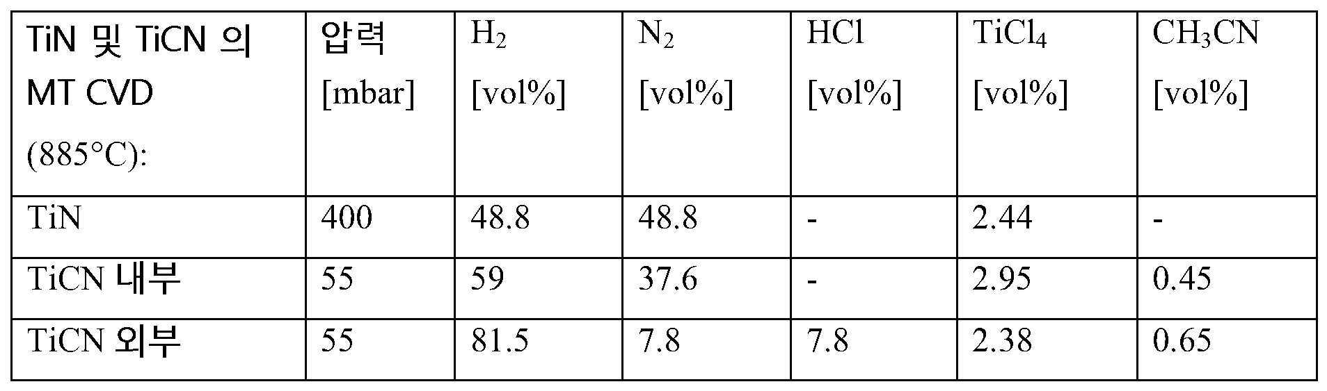
인서트들은 먼저 널리 알려진 MTCVD 기술을 이용하여 885 ℃ 에서 TiCl4, CH3CN, N2, HCl 및 H2 를 사용하여 얇은 약 0.4 ㎛ TiN-층으로 코팅된 다음 약 7 ㎛ TiCN 층으로 코팅되었다. TiCN 층의 MTCVD 증착의 초반부에서 TiCl4/CH3CN 의 체적비는 6.6 이였고, 뒤이어 증착 동안 TiCl4/CH3CN 의 비는 3.7 이였다. 표 1 에는 TiN 및 TiCN 증착의 세부 사항들을 나타냈다.The inserts were first coated with a thin about 0.4 μm TiN-layer using TiCl 4 , CH 3 CN, N 2 , HCl and H 2 at 885° C. using the well-known MTCVD technique and then with a layer of about 7 μm TiCN. At the beginning of the MTCVD deposition of the TiCN layer, the volume ratio of TiCl 4 /CH 3 CN was 6.6, followed by the ratio of TiCl 4 /CH 3 CN during deposition was 3.7. Table 1 shows the details of TiN and TiCN deposition.
표 1 (TiN 및 TiCN 의 MTCVD)Table 1 (MTCVD of TiN and TiCN)
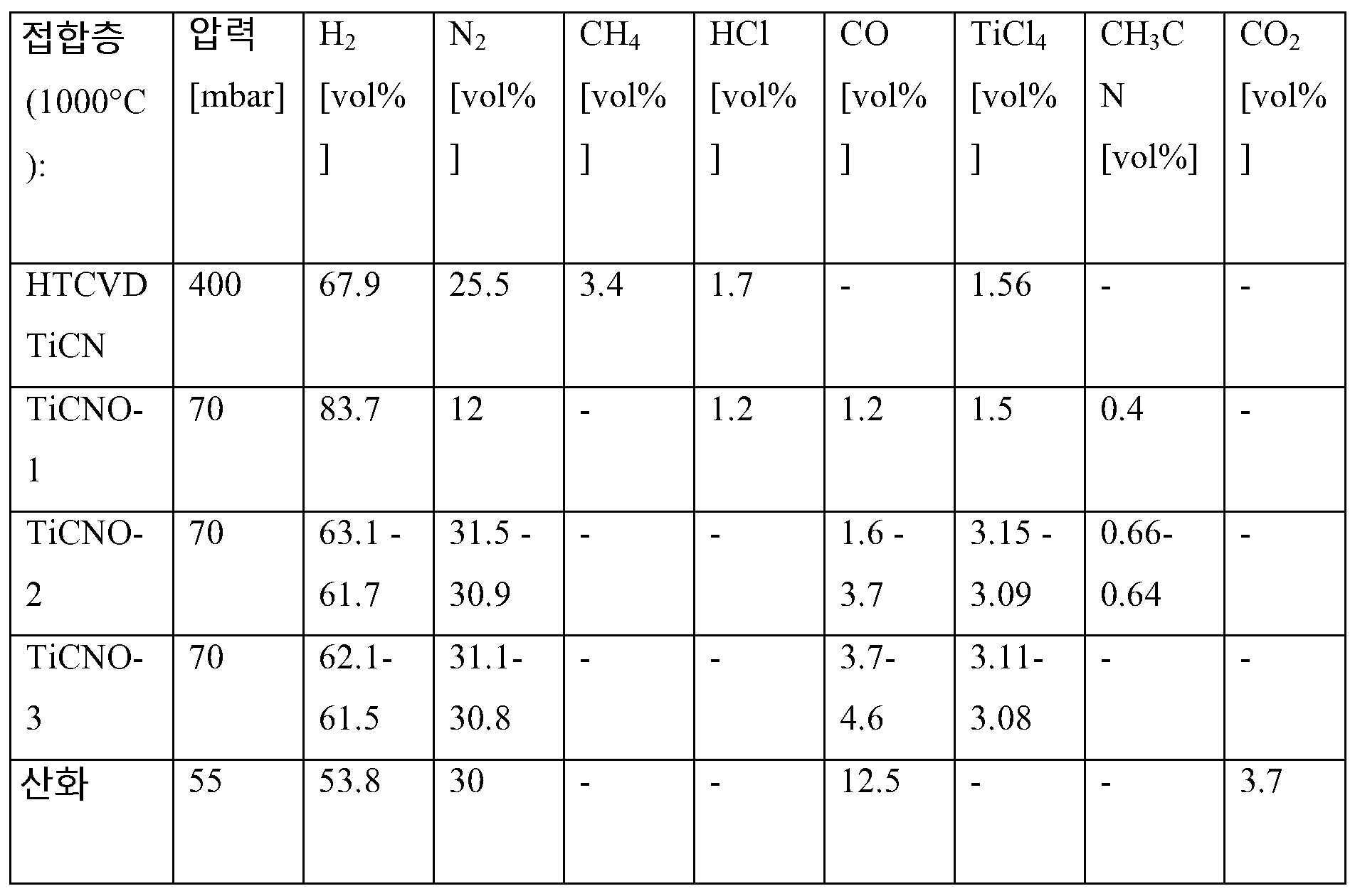
MTCVD TiCN 층의 상면에는 1 - 2 ㎛ 두께의 접합층이 4 개의 개별 반응 단계들로 구성된 공정에 의해 1000 ℃ 에서 증착되었다. 제 1 HTCVD TiCN 단계는 400 mbar 에서 TiCl4, CH4, N2, HCl 및 H2 를 사용하고; 제 2 단계 (TiCNO-1) 는 70 mbar 에서 TiCl4, CH3CN, CO, N2, 및 H2 를 사용하고; 제 3 단계 (TiCNO-2) 는 70 mbar 에서 TiCl4, CH3CN, CO, N2 및 H2 를 사용하고; 마지막 제 4 단계 (TiCNO-3) 는 70 mbar에서 TiCl4, CO, N2 및 H2 를 사용한다. 제 3 증착 단계 및 제 4 증착 단계 동안 가스들 중 일부는 표 2 에 나타낸 제 1 개시 레벨 및 제 2 정지 레벨에 의해 나타낸 바와 같이 연속적으로 변화되었다. 후속하는 α-Al2O3 핵형성을 개시하기 전에, CO2, CO, N2 및 H2 의 혼합물에서 4 분 동안 접합층이 산화되었다. 표 2 에는 접합층 증착의 세부 사항들을 나타냈다.On the top surface of the MTCVD TiCN layer, a 1 - 2 μm thick bonding layer was deposited at 1000 °C by a process consisting of four separate reaction steps. The first HTCVD TiCN step uses TiCl 4 , CH 4 , N 2 , HCl and H 2 at 400 mbar; The second stage (TiCNO-1) uses TiCl 4 , CH 3 CN, CO, N 2 , and H 2 at 70 mbar; the third stage (TiCNO-2) uses TiCl 4 , CH 3 CN, CO, N 2 and H 2 at 70 mbar; The fourth and final stage (TiCNO-3) uses TiCl 4 , CO, N 2 and H 2 at 70 mbar. During the third and fourth deposition steps some of the gases were continuously varied as indicated by the first onset level and the second stop level shown in Table 2. Prior to initiating subsequent α-Al 2 O 3 nucleation, the bonding layer was oxidized in a mixture of CO 2 , CO, N 2 and H 2 for 4 min. Table 2 shows the details of the bonding layer deposition.
표 2 (접합층 증착)Table 2 (bonding layer deposition)
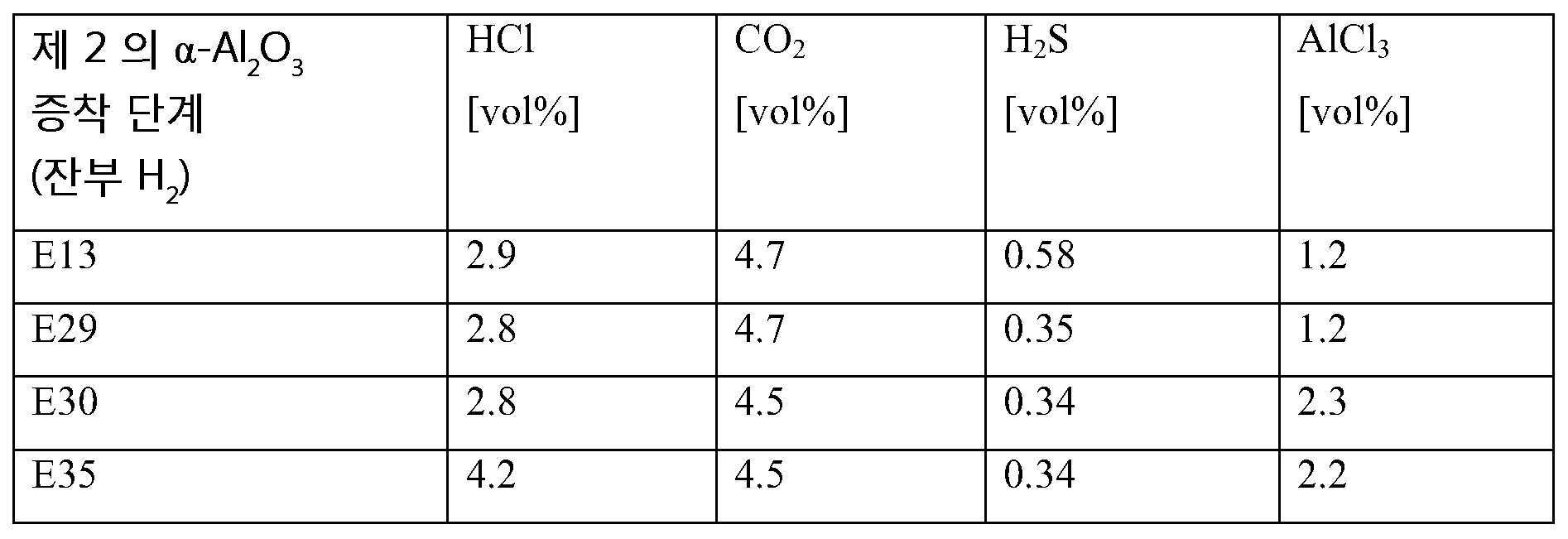
접합층의 상면에는 α-Al2O3 층이 증착되었다. 모든 α-Al2O3 층은 1000℃, 55 mbar 에서 두 단계로 증착되었다. 제 1 단계는 1.2 vol% AlCl3, 4.7 vol% CO2, 1.8 vol% HCl 및 잔부 H2 을 사용하여 약 0.1 ㎛ α-Al2O3 를 제공하고, 제 2 단계는 후술되는 바와 같이 전체 약 5 ㎛ 의 α-Al2O3 층 두께를 제공한다. 이는 α-Al2O3 의 제 2 단계만이 코팅들 (E13, E29, E30 및 E35) 사이에서 상이하다.An α-Al 2 O 3 layer was deposited on the upper surface of the bonding layer. All α-Al 2 O 3 layers were deposited in two steps at 1000° C. and 55 mbar. The first step provides about 0.1 μm α-Al 2 O 3 using 1.2 vol% AlCl 3 , 4.7 vol% CO 2 , 1.8 vol% HCl and the balance H 2 , and the second step provides about 0.1 μm α-Al 2 O 3 in total as described below. giving an α-Al 2 O 3 layer thickness of 5 μm. This differs between the coatings (E13, E29, E30 and E35) only in the second stage of α-Al 2 O 3 .
샘플들 E13C-1, E13C-2 및 E13S 에 대해, 제 2 단계의 α-Al2O3 층이 1.2 % AlCl3, 4.7 % CO2, 2.9 % HCl, 0.58 % H2S 및 잔부 H2 을 사용하여 증착되었다.For samples E13C-1, E13C-2 and E13S, the α-Al 2 O 3 layer of the second stage contained 1.2 % AlCl 3 , 4.7 % CO 2 , 2.9 % HCl, 0.58 % H 2 S and the balance H 2 was deposited using
샘플들 E29C-1, E29C-2 및 E29S 에 대해, 제 2 단계의 α-Al2O3 층이 1.2 % AlCl3, 4.7 % CO2, 2.8 % HCl, 0.35 % H2S 및 잔부 H2 을 사용하여 증착되었다.For samples E29C-1, E29C-2 and E29S, the α-Al 2 O 3 layer of the second step contained 1.2 % AlCl 3 , 4.7 % CO 2 , 2.8 % HCl, 0.35 % H 2 S and the balance H 2 . was deposited using
샘플들 E30C-1, E30C-2 및 E30S 에 대해, 제 2 단계의 α-Al2O3 층이 2.3 % AlCl3, 4.5 % CO2, 2.8 % HCl, 0.34 % H2S 및 잔부 H2 을 사용하여 증착되었다.For samples E30C-1, E30C-2 and E30S, the α-Al 2 O 3 layer of the second step contained 2.3% AlCl 3 , 4.5% CO 2 , 2.8% HCl, 0.34% H 2 S and the balance H 2 was deposited using
샘플들 E35C-1, E35C-2 및 E35S 에 대해, 제 2 단계의 α-Al2O3 층이 2.2 % AlCl3, 4.5 % CO2, 4.2 % HCl, 0.34 % H2S 및 잔부 H2 을 사용하여 증착되었다.For samples E35C-1, E35C-2 and E35S, the α-Al 2 O 3 layer of the second step contained 2.2 % AlCl 3 , 4.5 % CO 2 , 4.2 % HCl, 0.34 % H 2 S and the balance H 2 was deposited using
표 3 (제 2 의 α-Al2O3 증착 단계)Table 3 (Second α-Al 2 O 3 Deposition Step)
실시예 2 (참조)Example 2 (Reference)
선삭용의 ISO-타입 CNMG120408 의 초경 합금 기재들은 7.2 wt% Co, 2.7 wt% Ta, 1.8 wt% Ti, 0.4 wt% Nb, 0.1 wt% N 와 잔부 WC 으로부터 제조되었으며, 기재의 표면으로부터 입방정 탄화물이 사실상 없는 보디 깊이까지의 약 25 ㎛ 의 Co 농후 표면 구역을 포함한다.Cemented carbide substrates of ISO-type CNMG120408 for turning were prepared from 7.2 wt% Co, 2.7 wt% Ta, 1.8 wt% Ti, 0.4 wt% Nb, 0.1 wt% N and the balance WC, and cubic carbide was It contains a Co-rich surface area of about 25 μm to a body depth that is virtually absent.
인서트들은 먼저 널리 알려진 MTCVD 기술을 이용하여 885 ℃ 에서 TiCl4, CH3CN, N2, HCl 및 H2 를 사용하여 얇은 약 0.4 ㎛ TiN-층이 코팅된 다음 약 8 ㎛ TiCN 층이 코팅되었다. TiCN 층의 MTCVD 증착의 TiCl4/CH3CN 의 체적비는 코팅 R10 에 대해 2.2 였다. 코팅 R25 에 대해 TiCN 층의 MTCVD 증착의 초반부에서 TiCl4/CH3CN 의 체적비는 3.7 이였고, 뒤이어 증착 동안 TiCl4/CH3CN 의 비는 2.2 였다.The inserts were first coated with a thin about 0.4 μm TiN-layer using TiCl 4 , CH 3 CN, N 2 , HCl and H 2 at 885° C. using the well-known MTCVD technique, followed by an about 8 μm TiCN layer. The volume ratio of TiCl 4 /CH 3 CN of the MTCVD deposition of the TiCN layer was 2.2 for coating R10. The volume ratio of TiCl 4 /CH 3 CN at the beginning of the MTCVD deposition of the TiCN layer for coating R25 was 3.7, followed by the ratio of TiCl 4 /CH 3 CN during deposition of 2.2.
MTCVD TiCN 층의 상면에는 1 - 2 ㎛ 두께의 접합층이 3 개의 개별 반응 단계들로 구성된 공정에 의해 1000 ℃ 에서 증착되었다: 제 1 HTCVD TiCN 단계는 400 mbar 에서 TiCl4, CH4, N2, HCl 및 H2 를 사용하고; 제 2 단계는 70 mbar 에서 TiCl4, CH3CN, CO, N2, HCl 및 H2 를 사용하고; 마지막 제 3 단계는 70 mbar 에서 TiCl4, CH3CN, CO, N2 및 H2 를 사용한다. α-Al2O3 핵형성을 개시하기 전에, CO2, CO, N2 및 H2 의 혼합물에서 4 분 동안 접합층이 산화되었다.On the top surface of the MTCVD TiCN layer, a 1-2 μm thick bonding layer was deposited at 1000° C. by a process consisting of three separate reaction steps: the first HTCVD TiCN step was TiCl 4 , CH 4 , N 2 , at 400 mbar. HCl and H 2 are used; the second stage uses TiCl 4 , CH 3 CN, CO, N 2 , HCl and H 2 at 70 mbar; The third and final stage uses TiCl 4 , CH 3 CN, CO, N 2 and H 2 at 70 mbar. Prior to initiating α-Al 2 O 3 nucleation, the bonding layer was oxidized in a mixture of CO 2 , CO, N 2 and H 2 for 4 min.
이후에, α-Al2O3 층은 1000℃ (HTCVD), 55 mbar 에서 두 단계로 증착되었다. 제 1 단계는 1.2 vol% AlCl3, 4.7 vol% CO2, 1.8 vol% HCl 및 잔부 H2 을 사용하여 약 0.1 ㎛ α-Al2O3 를 제공하고, 제 2 단계는 1.16 % AlCl3, 4.7 % CO2, 2.9 % HCl, 0.58 % H2S 및 잔부 H2 을 사용하여 전체 약 5 ㎛ 의 α-Al2O3 층 두께를 제공한다.Then, the α-Al 2 O 3 layer was deposited in two steps at 1000° C. (HTCVD) and 55 mbar. The first step is using 1.2 vol% AlCl 3 , 4.7 vol% CO 2 , 1.8 vol% HCl and the balance H 2 to give about 0.1 μm α-Al 2 O 3 , the second step is 1.16% AlCl 3 , 4.7 % CO 2 , 2.9 % HCl, 0.58 % H 2 S and the balance H 2 are used to give a total α-Al 2 O 3 layer thickness of about 5 μm.
R10 및 R25 코팅들 (즉, 샘플들 R10C-1, R10C-2, R25C-1, R25C-2 에 대한 코팅들) 은 또한 약 1 ㎛ 두께의 TiN 의 최외측 층을 포함한다.The R10 and R25 coatings (ie, the coatings for samples R10C-1, R10C-2, R25C-1, R25C-2) also include an outermost layer of TiN about 1 μm thick.
실시예 3 (조직 분석)Example 3 (tissue analysis)
XRD 는 전술한 바와 같은 방법에 따라 α-Al2O3 및 TiCN 의 TC 값들을 분석하기 위하여 사용되었다. 코팅된 CNMG120408 기재의 각각의 두 개의 샘플들은 분석된 그리고 후속하여 마모 테스트된 조직인 반면, 코팅된 SNMA120408 기재는 단지 분석된 조직이였다. 층 두께들은 1000x 배율로 각각의 코팅의 단면을 연구함으로써 광 광학 현미경으로 분석되었고 양자의 접합층 및 초기 TiN 층은 표 2 에 주어진 TiCN 층 두께에 포함된다. 표 4 에는 결과들을 나타냈다.XRD was used to analyze the TC values of α-Al 2 O 3 and TiCN according to the method described above. Each of the two samples of the coated CNMG120408 substrate was tissue analyzed and subsequently abrasion tested, whereas the coated SNMA120408 substrate was the only tissue analyzed. The layer thicknesses were analyzed by light optical microscopy by studying the cross-section of each coating at 1000x magnification and both the bonding layer and the initial TiN layer were included in the TiCN layer thickness given in Table 2. Table 4 shows the results.
표 4 (두께 및 회절 데이터)Table 4 (thickness and diffraction data)

실시예 4 (절삭 테스트)Example 4 (Cutting Test)
절삭 마모 테스트 이전에, 인서트들은 습식 블라스팅 장비로 수중 알루미나 슬러리를 이용하여 레이크 면에 대해 블라스팅되었고, 절삭 인서트의 레이크면과 q블라스터 슬러리의 방향 사이의 각도는 약 90°였다. 알루미나 그리트 (grits) 는 F220 이였고, 건으로의 슬러리 압력은 1.8 bar 였고, 건으로의 공기압은 2.2 bar 였고, 단위 면적당 블라스팅 평균 시간은 4.4 초였고, 건 노즐로부터 인서트 표면까지의 거리는 약 145 ㎜ 였다. 블라스팅의 목적은 코팅의 잔류 응력과 표면 거칠기에 영향을 주기 위한 것이고, 그럼으로써 후속하는 선삭 테스트에서 인서트들의 특성을 개선시키기 위한 것이다.Prior to the cutting wear test, the inserts were blasted against the rake face using an alumina slurry in water with wet blasting equipment, and the angle between the rake face of the cutting insert and the direction of the qblaster slurry was about 90°. The alumina grits were F220, the slurry pressure to the gun was 1.8 bar, the air pressure to the gun was 2.2 bar, the average blasting time per unit area was 4.4 seconds, and the distance from the gun nozzle to the insert surface was about 145 mm. The purpose of blasting is to influence the residual stresses and surface roughness of the coating, thereby improving the properties of the inserts in subsequent turning tests.
블라스팅되는 ISO 타입 CNMG120408 의 코팅된 절삭 공구들은 이하의 절삭 데이터를 사용하여 볼베어링강 (100CrMo7-3) 에 길이방향 선삭 테스트하였다;Blasting coated cutting tools of ISO type CNMG120408 were subjected to longitudinal turning tests on ball bearing steel (100CrMo7-3) using the following cutting data;
절삭 속도 vc: 220 m/minCutting speed v c : 220 m/min
절삭 이송, f : 0.3 mm/revolutionCutting feed, f : 0.3 mm/revolution
절삭 깊이, ap: 2 mm.Depth of cut, a p : 2 mm.
물 혼화성 금속 작업 유체를 사용하였다.A water miscible metal working fluid was used.
절삭 공구 당 하나의 절삭 에지를 평가했다.One cutting edge was evaluated per cutting tool.
크레이터 마모의 분석에 있어서, 광 광학 현미경을 사용하여 노출된 기재의 면적이 측정되었다. 노출된 기재의 표면적이 0.2 ㎟ 를 초과할 때, 공구의 수명이 달한 것으로 판단하였다. 각 절삭 공구의 마모는 2 분 절삭후 광 광학 현미경에서 평가되었다. 그 후, 공구 수명 기준에 도달할 때까지, 각각 2 분 운전후 측정으로 절삭 공정을 계속하였다. 크레이터 면적의 크기가 0.2 ㎟ 를 초과할 때, 공구 수명 기준이 충족될 때까지의 시간을 마지막 두 측정 사이에 가정된 일정한 마모율에 기초하여 추정하였다. 크레이터 마모와 더불어, 플랭크 마모도 역시 관찰되었지만, 그러나 이 시험에서는 공구 수명에 영향을 주지 않았다. 두 개의 나란한 테스트들이 코팅의 각각의 유형에 대해 실시되었고, 예를 들어 샘플 E13C-1 은 마모 테스트 1 에서 테스트되었고, 샘플 E13C-2 는 마모 테스트 2 에서 테스트되었다. SNMA120408 의 기하학적 형상을 갖는 샘플들은 어떠한 절삭 테스트에서도 평가되지 않았다. 표 5 에는 결과들을 나타냈다.For analysis of crater wear, the area of the exposed substrate was measured using a light optical microscope. When the surface area of the exposed substrate exceeds 0.2 mm 2 , it was determined that the life of the tool had been reached. The wear of each cutting tool was evaluated under a light optical microscope after 2 minutes of cutting. Thereafter, the cutting process was continued with measurements after each 2 min run until the tool life criterion was reached. When the size of the crater area exceeds 0.2 mm 2 , the time until the tool life criterion is met was estimated based on the assumed constant wear rate between the last two measurements. In addition to crater wear, flank wear was also observed, but did not affect tool life in this test. Two side-by-side tests were run for each type of coating, eg sample E13C-1 was tested in wear test 1 and sample E13C-2 was tested in wear test 2. Samples with the geometry of SNMA120408 were not evaluated in any cutting tests. Table 5 shows the results.
표 5 (마모 성능)Table 5 (Abrasion Performance)

본 발명은 여러 예시적인 실시형태들에 대하여 설명되었지만, 본 발명이 개시된 예시적인 실시형태들에 한정되지 않으며, 반대로 첨부된 청구범위내의 여러 변형과 등가의 배치들을 포함하는 것으로 이해되어야 한다. While the present invention has been described with respect to several exemplary embodiments, it is to be understood that the invention is not limited to the disclosed exemplary embodiments, but to the contrary, it is intended to cover various modifications and equivalent arrangements within the scope of the appended claims.
Claims (15)
상기 α-Al2O3 층은, CuKα 방사선과 θ-2θ 스캔을 사용하여 X-선 회절에 의해 측정했을 때, Harris 공식

에 따라 정의된 조직 계수 TC(hkl) 를 나타내고,
여기서 I(hkl) 는 (hkl) 반사의 측정된 강도 (적분 면적; integrated area) 이고, I0(hkl) 는 ICDD 의 PDF-card No. 00-010-0173 에 따른 표준 강도이고, n 은 연산에 사용된 반사들의 수이고, 여기서 사용된 (hkl) 반사들은 (1 0 4), (1 1 0), (1 1 3), (0 2 4), (1 1 6), (2 1 4), (3 0 0) 및 (0 0 12) 이고,
TC(0 0 12) 는 7.2 이상, 또는 7.4 이상, 또는 7.5 이상, 또는 7.6 이상, 또는 7.7 이상이고,
I(0 0 12)/I(0 1 14) 의 비는 1 이상, 또는 1.5 이상, 또는 1.7 이상, 또는 2 이상이고,
상기 코팅은 상기 기재와 상기 α-Al2O3 층 사이에 위치된 MTCVD TiCN 층을 추가로 포함하고,
상기 α-Al2O3 층과 상기 기재 사이에 위치된 TiCN 층은, CuKα 방사선과 θ-2θ 스캔을 사용하여 X-선 회절에 의해 측정했을 때, Harris 공식에 따라 정의된 조직 계수 TC(hkl) 를 나타내고, 여기서 I(hkl) 는 (hkl) 반사의 측정된 강도 (적분 면적) 이고, I0(hkl) 는 ICDD 의 PDF-card No. 42-1489 에 따른 표준 강도이고, n 은 반사들의 수이고, 연산에 사용된 반사들은 (1 1 1), (2 0 0), (2 2 0), (3 1 1), (3 3 1), (4 2 0), (4 2 2) 및 (5 1 1) 이고,
상기 TiCN 층의 TC(3 1 1) + TC(4 2 2) 는 4 이상, 또는 5 이상, 또는 6 이상, 또는 7 이상인 것을 특징으로 하는, 코팅된 절삭 공구.A coated cutting tool comprising a substrate coated with a coating comprising a layer of α-Al 2 O 3 ,
The α-Al 2 O 3 layer, as measured by X-ray diffraction using CuKα radiation and θ-2θ scans, was determined by Harris formula
represents the tissue coefficient TC(hkl) defined according to
where I(hkl) is the measured intensity (integrated area) of the (hkl) reflection, and I 0 (hkl) is the PDF-card No. of ICDD. standard intensity according to 00-010-0173, n is the number of reflections used in the calculation, where (hkl) reflections used are (1 0 4), (1 1 0), (1 1 3), (0 2 4), (1 1 6), (2 1 4), (3 0 0) and (0 0 12),
TC(0 0 12) is 7.2 or more, or 7.4 or more, or 7.5 or more, or 7.6 or more, or 7.7 or more,
the ratio of I(0 0 12)/I(0 1 14) is 1 or more, or 1.5 or more, or 1.7 or more, or 2 or more,
the coating further comprises an MTCVD TiCN layer positioned between the substrate and the α-Al 2 O 3 layer,
The TiCN layer positioned between the α-Al 2 O 3 layer and the substrate had a tissue modulus, TC(hkl), defined according to the Harris formula, as measured by X-ray diffraction using CuKα radiation and θ-2θ scans. where I(hkl) is the measured intensity (integral area) of the (hkl) reflection, and I 0 (hkl) is the PDF-card No. of ICDD. standard intensity according to 42-1489, n is the number of reflections, the reflections used in the calculation are (1 1 1), (2 0 0), (2 2 0), (3 1 1), (3 3 1 ), (4 2 0), (4 2 2) and (5 1 1),
TC(3 1 1) + TC(4 2 2) of the TiCN layer is 4 or more, or 5 or more, or 6 or more, or 7 or more.
상기 TiCN 층은 3 이상의, 또는 3.5 이상의 TC(4 2 2) 를 나타내는 것을 특징으로 하는, 코팅된 절삭 공구.The method of claim 1,
Coated cutting tool, characterized in that the TiCN layer exhibits a TC(4 2 2) of 3 or more, or 3.5 or more.
상기 코팅된 절삭 공구의 기재는 4 - 12 wt% Co,
주기율표의 IVb, Vb 및 VIb 족으로부터의 금속들의 0.1 - 10 wt% 입방정 탄화물, 질화물 또는 탄질화물, 및
잔부 WC 를 포함하는 초경 합금으로 이루어지는, 코팅된 절삭 공구.The method of claim 1,
The substrate of the coated cutting tool is 4 - 12 wt% Co,
0.1 - 10 wt% cubic carbides, nitrides or carbonitrides of metals from groups IVb, Vb and VIb of the periodic table, and
A coated cutting tool consisting of a cemented carbide with the balance WC.
상기 코팅된 절삭 공구의 기재는 6 - 8 wt% Co,
Ti, Nb, Ta 또는 그의 조합의 0.1 - 10 wt% 입방정 탄화물, 질화물 또는 탄질화물, 및
잔부 WC 를 포함하는 초경 합금으로 이루어지는, 코팅된 절삭 공구.The method of claim 1,
The substrate of the coated cutting tool is 6 - 8 wt% Co,
0.1 - 10 wt % cubic carbide, nitride or carbonitride of Ti, Nb, Ta or combinations thereof, and
A coated cutting tool consisting of a cemented carbide with the balance WC.
상기 기재는 바인더 상이 농후한 표면 구역을 갖는 초경 합금으로 이루어지고,
상기 바인더 상이 농후한 표면 구역의 두께는, 상기 기재의 표면으로부터 상기 기재의 중심을 향해 측정했을 때에 5 - 35㎛ 인, 코팅된 절삭 공구.The method of claim 1,
The substrate consists of a cemented carbide having a surface area rich in binder phase,
wherein the thickness of the surface region rich in the binder phase is 5-35 μm, measured from the surface of the substrate toward the center of the substrate.
상기 바인더 상이 농후한 표면 구역은 상기 기재의 중심에서의 바인더 상 함량보다 적어도 50 % 더 높은 평균 바인더 상 함량을 갖는, 코팅된 절삭 공구.6. The method of claim 5,
wherein the surface region rich in the binder phase has an average binder phase content at least 50% higher than the binder phase content in the center of the substrate.
상기 기재는 입방정 탄화물이 없는 표면 구역을 갖는 초경 합금으로 이루어지고,
상기 입방정 탄화물이 없는 표면 구역의 두께는, 상기 기재의 표면으로부터 상기 기재의 중심을 향해 측정했을 때에 5 - 35 ㎛ 인, 코팅된 절삭 공구.The method of claim 1,
The substrate consists of a cemented carbide having a surface area free of cubic carbides,
wherein the thickness of the cubic carbide-free surface region is 5-35 μm, measured from the surface of the substrate towards the center of the substrate.
TC(2 2 0) 는 0.5 이하, 또는 0.3 이하, 또는 0.2 이하, 또는 0.1 이하인, 코팅된 절삭 공구.The method of claim 1,
TC(2 2 0) is 0.5 or less, or 0.3 or less, or 0.2 or less, or 0.1 or less.
상기 α-Al2O3 층의 두께는 2 - 20 ㎛ 인 것을 특징으로 하는, 코팅된 절삭 공구.The method of claim 1,
The coated cutting tool, characterized in that the thickness of the α-Al 2 O 3 layer is 2 - 20 μm.
상기 MTCVD TiCN 층의 두께는 4 - 20 ㎛ 인 것을 특징으로 하는, 코팅된 절삭 공구.The method of claim 1,
The coated cutting tool, characterized in that the thickness of the MTCVD TiCN layer is 4 - 20 μm.
상기 코팅은, HTCVD 증착된 TiN, TiCN, TiCNO, TiCO 또는 그 조합을 포함하는 접합층으로서, 상기 MTCVD TiCN 층의 최외측에 위치되고 또한 상기 α-Al2O3 층에 인접하는 상기 접합층을 추가로 포함하는 것을 특징으로 하는, 코팅된 절삭 공구.The method of claim 1,
The coating is a bonding layer comprising HTCVD deposited TiN, TiCN, TiCNO, TiCO, or a combination thereof, the bonding layer being located on the outermost side of the MTCVD TiCN layer and adjacent to the α-Al 2 O 3 layer. Coated cutting tool, further comprising.
상기 접합층의 두께는 0.5 - 2 ㎛ 인 것을 특징으로 하는, 코팅된 절삭 공구.12. The method of claim 11,
Coated cutting tool, characterized in that the thickness of the bonding layer is 0.5 - 2 ㎛.
상기 기재는 초경 합금, 서멧 (cermet), 또는 세라믹인 것을 특징으로 하는, 코팅된 절삭 공구.13. The method according to any one of claims 1 to 12,
The coated cutting tool, characterized in that the substrate is a cemented carbide, cermet, or ceramic.
상기 코팅된 절삭 공구는 강, 또는 합금강, 탄소강 또는 강인강 (tough hardened steel) 의 선삭 작업에서 사용되는 것을 특징으로 하는, 코팅된 절삭 공구.13. The method according to any one of claims 1 to 12,
Coated cutting tool, characterized in that the coated cutting tool is used in the turning operation of steel or alloy steel, carbon steel or tough hardened steel.
상기 코팅된 절삭 공구는 강, 또는 합금강, 탄소강 또는 강인강 (tough hardened steel) 의 선삭 작업에서 사용되는 것을 특징으로 하는, 코팅된 절삭 공구.14. The method of claim 13,
Coated cutting tool, characterized in that the coated cutting tool is used in the turning operation of steel or alloy steel, carbon steel or tough hardened steel.
Applications Claiming Priority (3)
| Application Number | Priority Date | Filing Date | Title |
|---|---|---|---|
| EP14199190 | 2014-12-19 | ||
| EP14199190.1 | 2014-12-19 | ||
| KR1020150181989A KR102445504B1 (en) | 2014-12-19 | 2015-12-18 | Cvd coated cutting tool |
Related Parent Applications (1)
| Application Number | Title | Priority Date | Filing Date |
|---|---|---|---|
| KR1020150181989A Division KR102445504B1 (en) | 2014-12-19 | 2015-12-18 | Cvd coated cutting tool |
Publications (2)
| Publication Number | Publication Date |
|---|---|
| KR20220132487A true KR20220132487A (en) | 2022-09-30 |
| KR102478912B1 KR102478912B1 (en) | 2022-12-19 |
Family
ID=52282455
Family Applications (2)
| Application Number | Title | Priority Date | Filing Date |
|---|---|---|---|
| KR1020150181989A KR102445504B1 (en) | 2014-12-19 | 2015-12-18 | Cvd coated cutting tool |
| KR1020220116232A KR102478912B1 (en) | 2014-12-19 | 2022-09-15 | Cvd coated cutting tool |
Family Applications Before (1)
| Application Number | Title | Priority Date | Filing Date |
|---|---|---|---|
| KR1020150181989A KR102445504B1 (en) | 2014-12-19 | 2015-12-18 | Cvd coated cutting tool |
Country Status (8)
| Country | Link |
|---|---|
| US (1) | US9987687B2 (en) |
| EP (1) | EP3034653B1 (en) |
| JP (2) | JP7084682B2 (en) |
| KR (2) | KR102445504B1 (en) |
| CN (1) | CN105714268B (en) |
| ES (1) | ES2732034T3 (en) |
| PL (1) | PL3034653T3 (en) |
| RU (1) | RU2704949C2 (en) |
Families Citing this family (46)
| Publication number | Priority date | Publication date | Assignee | Title |
|---|---|---|---|---|
| EP3034652A1 (en) * | 2014-12-19 | 2016-06-22 | Sandvik Intellectual Property AB | CVD coated cutting tool |
| RU2704949C2 (en) | 2014-12-19 | 2019-10-31 | Сандвик Интеллекчуал Проперти Аб | Cvd coated cutting tool |
| US10639724B2 (en) | 2016-02-18 | 2020-05-05 | Tungaloy Corporation | Coated cutting tool |
| JP6898361B2 (en) * | 2016-06-21 | 2021-07-07 | サンドビック インテレクチュアル プロパティー アクティエボラーグ | CVD coated cutting tool |
| CN107557755B (en) * | 2016-07-01 | 2020-05-01 | 山特维克知识产权股份有限公司 | With { 001 } textured kappa-Al2O3CVD coated cutting tool for layers |
| KR101687142B1 (en) | 2016-07-20 | 2016-12-15 | 한국야금 주식회사 | Hard coated layer for cutting tools |
| JP6229911B1 (en) * | 2016-10-19 | 2017-11-15 | 株式会社タンガロイ | Coated cutting tool |
| JP6229912B1 (en) * | 2016-10-21 | 2017-11-15 | 株式会社タンガロイ | Coated cutting tool |
| US11717893B2 (en) | 2016-10-24 | 2023-08-08 | Tungaloy Corporation | Coated cutting tool |
| EP3533544B1 (en) * | 2016-10-25 | 2023-08-09 | Tungaloy Corporation | Coated cutting tool |
| JP6210346B1 (en) * | 2016-11-02 | 2017-10-11 | 株式会社タンガロイ | Coated cutting tool |
| JP6210347B1 (en) * | 2016-11-04 | 2017-10-11 | 株式会社タンガロイ | Coated cutting tool |
| JP6210348B1 (en) * | 2016-11-08 | 2017-10-11 | 株式会社タンガロイ | Coated cutting tool |
| WO2018088114A1 (en) * | 2016-11-14 | 2018-05-17 | 株式会社タンガロイ | Coated cutting tool |
| EP3542935B1 (en) * | 2016-11-17 | 2023-08-09 | Tungaloy Corporation | Coated cutting tool |
| CN106583731B (en) * | 2016-12-13 | 2018-03-30 | 成都邦普切削刀具股份有限公司 | A kind of preparation method of coated cutting tool for the processing of train wheel hub |
| US10946454B2 (en) * | 2017-01-07 | 2021-03-16 | Tungaloy Corporation | Coated cutting tool |
| US11286570B2 (en) | 2017-01-26 | 2022-03-29 | Walter Ag | Coated cutting tool |
| JP6973026B2 (en) * | 2017-02-20 | 2021-11-24 | 株式会社タンガロイ | Cover cutting tool |
| EP3366796A1 (en) * | 2017-02-28 | 2018-08-29 | Sandvik Intellectual Property AB | Coated cutting tool |
| BR112019020882A2 (en) * | 2017-04-07 | 2020-04-28 | Sandvik Intellectual Property | coated cutting tool |
| JP6521130B2 (en) * | 2017-04-21 | 2019-05-29 | 株式会社タンガロイ | Coated cutting tool |
| JP6521127B2 (en) * | 2017-04-21 | 2019-05-29 | 株式会社タンガロイ | Coated cutting tool |
| KR102513063B1 (en) * | 2017-06-07 | 2023-03-22 | 산드빅 인터렉츄얼 프로퍼티 에이비 | coated cutting tools |
| JP6727553B2 (en) * | 2017-09-14 | 2020-07-22 | 株式会社タンガロイ | Coated cutting tools |
| WO2020002500A1 (en) * | 2018-06-28 | 2020-01-02 | Ab Sandvik Coromant | Coated cutting tool |
| WO2020050261A1 (en) | 2018-09-05 | 2020-03-12 | 京セラ株式会社 | Coated tool and cutting tool |
| WO2020050264A1 (en) * | 2018-09-05 | 2020-03-12 | 京セラ株式会社 | Coated tool and cutting tool |
| KR102130725B1 (en) | 2018-10-23 | 2020-07-06 | 배영규 | Tempered glass cutting tools |
| KR20210087049A (en) | 2018-11-29 | 2021-07-09 | 교세라 가부시키가이샤 | Covered tool and cutting tool having same |
| US11911829B2 (en) * | 2018-11-29 | 2024-02-27 | Kyocera Corporation | Coated tool and cutting tool including same |
| EP3871815A4 (en) * | 2019-02-19 | 2021-09-01 | Sumitomo Electric Hardmetal Corp. | Cutting tool |
| BR112021023613A2 (en) * | 2019-05-27 | 2022-01-04 | Sandvik Coromant Ab | A coated cutting tool |
| BR112021023538A2 (en) * | 2019-05-27 | 2022-01-18 | Sandvik Coromant Ab | A coated cutting tool |
| EP4022109A1 (en) * | 2019-08-30 | 2022-07-06 | Seco Tools Ab | Coated cutting tool |
| JP7141601B2 (en) * | 2019-12-19 | 2022-09-26 | 株式会社タンガロイ | coated cutting tools |
| EP3848485A1 (en) | 2020-01-10 | 2021-07-14 | Sakari Ruppi | Improved alpha alumina layer deposited with controlled textures |
| EP4129539A4 (en) * | 2020-03-25 | 2024-04-24 | Mitsubishi Materials Corp | Surface-coated cutting tool |
| EP4006199A1 (en) * | 2020-11-26 | 2022-06-01 | AB Sandvik Coromant | A coated cutting tool |
| WO2022201229A1 (en) * | 2021-03-22 | 2022-09-29 | 住友電工ハードメタル株式会社 | Cutting tool |
| EP4091748A4 (en) * | 2021-03-22 | 2023-04-26 | Sumitomo Electric Hardmetal Corp. | Cutting tool |
| CN115397586A (en) * | 2021-03-22 | 2022-11-25 | 住友电工硬质合金株式会社 | Cutting tool |
| CN117355636A (en) | 2021-05-27 | 2024-01-05 | 山特维克科洛曼特公司 | Coated cutting tool |
| EP4347921A1 (en) * | 2021-05-27 | 2024-04-10 | AB Sandvik Coromant | A coated cutting tool |
| CN113584459B (en) * | 2021-08-03 | 2023-09-22 | 赣州澳克泰工具技术有限公司 | Texture enhanced kappa-Al 2 O 3 Coated tool and method for producing the same |
| WO2024083480A1 (en) * | 2022-10-21 | 2024-04-25 | Ab Sandvik Coromant | A coated cutting tool |
Citations (2)
| Publication number | Priority date | Publication date | Assignee | Title |
|---|---|---|---|---|
| WO2013037998A2 (en) * | 2011-09-16 | 2013-03-21 | Walter Ag | Sulfur containing alpha-alumina coated cutting tool |
| KR20140105754A (en) * | 2011-12-14 | 2014-09-02 | 산드빅 인터렉츄얼 프로퍼티 에이비 | Coated cutting tool and method of manufacturing the same |
Family Cites Families (21)
| Publication number | Priority date | Publication date | Assignee | Title |
|---|---|---|---|---|
| SE501527C2 (en) * | 1992-12-18 | 1995-03-06 | Sandvik Ab | Methods and articles when coating a cutting tool with an alumina layer |
| SE502174C2 (en) * | 1993-12-23 | 1995-09-04 | Sandvik Ab | Methods and articles when coating a cutting tool with an alumina layer |
| SE509201C2 (en) * | 1994-07-20 | 1998-12-14 | Sandvik Ab | Aluminum oxide coated tool |
| JP3658948B2 (en) * | 1997-10-30 | 2005-06-15 | 住友電気工業株式会社 | Coated cemented carbide |
| SE520802C2 (en) * | 1997-11-06 | 2003-08-26 | Sandvik Ab | Cutting tool coated with alumina and process for its manufacture |
| US6284390B1 (en) * | 1998-06-12 | 2001-09-04 | United Technologies Corporation | Thermal barrier coating system utilizing localized bond coat and article having the same |
| FR2814473B1 (en) * | 2000-09-25 | 2003-06-27 | Snecma Moteurs | PROCESS FOR MAKING A PROTECTIVE COATING FORMING THERMAL BARRIER WITH BONDING UNDERLAYER ON A SUBSTRATE IN SUPERALLY AND PART OBTAINED |
| SE525581C2 (en) * | 2002-05-08 | 2005-03-15 | Seco Tools Ab | Cutting coated with alumina made with CVD |
| DE10255822B4 (en) * | 2002-11-29 | 2004-10-28 | Fraunhofer-Gesellschaft zur Förderung der angewandten Forschung e.V. | Process for the vapor deposition of ribbon-shaped substrates with a transparent barrier layer made of aluminum oxide |
| SE527346C2 (en) | 2003-04-24 | 2006-02-14 | Seco Tools Ab | Cutter with coating of layers of MTCVD-Ti (C, N) with controlled grain size and morphology and method of coating the cutter |
| SE528109C2 (en) * | 2004-07-12 | 2006-09-05 | Sandvik Intellectual Property | Phantom inserts, especially for phase milling of steel sheet for oil pipes, and ways of manufacturing the same |
| JP4518260B2 (en) | 2005-01-21 | 2010-08-04 | 三菱マテリアル株式会社 | Surface-coated cermet cutting tool whose hard coating layer exhibits excellent chipping resistance in high-speed intermittent cutting |
| SE529051C2 (en) | 2005-09-27 | 2007-04-17 | Seco Tools Ab | Cutting tool inserts coated with alumina |
| EP1897970B2 (en) * | 2006-09-05 | 2016-06-15 | Tungaloy Corporation | Coated cutting tool and method for producing the same |
| EP1905870A3 (en) | 2006-09-27 | 2008-05-14 | Seco Tools Ab | Alumina layer with enhanced texture |
| JP4946333B2 (en) | 2006-10-10 | 2012-06-06 | 三菱マテリアル株式会社 | Surface coated cutting tool with excellent chipping resistance due to hard coating layer |
| US8449992B2 (en) * | 2008-02-27 | 2013-05-28 | Kyocera Corporation | Surface-coated member and cutting tool |
| WO2012144088A1 (en) * | 2011-04-21 | 2012-10-26 | 住友電工ハードメタル株式会社 | Surface-coated cutting tool and method for manufacturing same |
| DE102011053705A1 (en) * | 2011-09-16 | 2013-03-21 | Walter Ag | Cutting insert and method for its production |
| WO2014198881A1 (en) * | 2013-06-14 | 2014-12-18 | Sandvik Intellectual Property Ab | Coated cutting tool |
| RU2704949C2 (en) | 2014-12-19 | 2019-10-31 | Сандвик Интеллекчуал Проперти Аб | Cvd coated cutting tool |
-
2015
- 2015-12-11 RU RU2015153189A patent/RU2704949C2/en active
- 2015-12-14 JP JP2015242918A patent/JP7084682B2/en active Active
- 2015-12-17 EP EP15200771.2A patent/EP3034653B1/en not_active Revoked
- 2015-12-17 ES ES15200771T patent/ES2732034T3/en active Active
- 2015-12-17 PL PL15200771T patent/PL3034653T3/en unknown
- 2015-12-18 US US14/975,626 patent/US9987687B2/en active Active
- 2015-12-18 KR KR1020150181989A patent/KR102445504B1/en active IP Right Grant
- 2015-12-21 CN CN201510964707.9A patent/CN105714268B/en active Active
-
2022
- 2022-06-03 JP JP2022090620A patent/JP7394172B2/en active Active
- 2022-09-15 KR KR1020220116232A patent/KR102478912B1/en active IP Right Grant
Patent Citations (2)
| Publication number | Priority date | Publication date | Assignee | Title |
|---|---|---|---|---|
| WO2013037998A2 (en) * | 2011-09-16 | 2013-03-21 | Walter Ag | Sulfur containing alpha-alumina coated cutting tool |
| KR20140105754A (en) * | 2011-12-14 | 2014-09-02 | 산드빅 인터렉츄얼 프로퍼티 에이비 | Coated cutting tool and method of manufacturing the same |
Also Published As
| Publication number | Publication date |
|---|---|
| CN105714268A (en) | 2016-06-29 |
| JP7394172B2 (en) | 2023-12-07 |
| RU2015153189A3 (en) | 2019-05-14 |
| JP2016137564A (en) | 2016-08-04 |
| US9987687B2 (en) | 2018-06-05 |
| PL3034653T3 (en) | 2019-09-30 |
| KR102478912B1 (en) | 2022-12-19 |
| US20160175940A1 (en) | 2016-06-23 |
| EP3034653B1 (en) | 2019-04-03 |
| JP2022126683A (en) | 2022-08-30 |
| RU2015153189A (en) | 2017-06-20 |
| KR20160075367A (en) | 2016-06-29 |
| EP3034653A1 (en) | 2016-06-22 |
| CN105714268B (en) | 2019-12-10 |
| RU2704949C2 (en) | 2019-10-31 |
| KR102445504B1 (en) | 2022-09-20 |
| ES2732034T3 (en) | 2019-11-20 |
| JP7084682B2 (en) | 2022-06-15 |
Similar Documents
| Publication | Publication Date | Title |
|---|---|---|
| KR102478912B1 (en) | Cvd coated cutting tool | |
| CN107002237B (en) | CVD coated cutting tool | |
| JP6898361B2 (en) | CVD coated cutting tool | |
| RU2766604C2 (en) | Coated cutting tool | |
| KR20190024896A (en) | CVD coated cutting tool | |
| KR102576891B1 (en) | coated cutting tools | |
| EP3607110B1 (en) | Coated cutting tool |
Legal Events
| Date | Code | Title | Description |
|---|---|---|---|
| A107 | Divisional application of patent | ||
| E701 | Decision to grant or registration of patent right | ||
| GRNT | Written decision to grant |