KR20220131978A - substrate transfer device - Google Patents
substrate transfer device Download PDFInfo
- Publication number
- KR20220131978A KR20220131978A KR1020227029188A KR20227029188A KR20220131978A KR 20220131978 A KR20220131978 A KR 20220131978A KR 1020227029188 A KR1020227029188 A KR 1020227029188A KR 20227029188 A KR20227029188 A KR 20227029188A KR 20220131978 A KR20220131978 A KR 20220131978A
- Authority
- KR
- South Korea
- Prior art keywords
- pulley
- band
- end effector
- articulated arm
- drive
- Prior art date
Links
- 239000000758 substrate Substances 0.000 title claims abstract description 148
- 238000012546 transfer Methods 0.000 title claims description 117
- 239000012636 effector Substances 0.000 claims abstract description 282
- 230000005540 biological transmission Effects 0.000 claims abstract description 102
- 238000000034 method Methods 0.000 claims description 63
- 238000004804 winding Methods 0.000 claims description 61
- 230000009467 reduction Effects 0.000 claims description 34
- 230000033001 locomotion Effects 0.000 claims description 28
- 230000009977 dual effect Effects 0.000 claims description 20
- 238000012545 processing Methods 0.000 description 43
- 230000002093 peripheral effect Effects 0.000 description 36
- 210000000245 forearm Anatomy 0.000 description 20
- 210000000707 wrist Anatomy 0.000 description 18
- 238000010586 diagram Methods 0.000 description 10
- 230000008878 coupling Effects 0.000 description 7
- 238000010168 coupling process Methods 0.000 description 7
- 238000005859 coupling reaction Methods 0.000 description 7
- 238000009434 installation Methods 0.000 description 7
- 238000009760 electrical discharge machining Methods 0.000 description 6
- 239000002184 metal Substances 0.000 description 6
- 230000007704 transition Effects 0.000 description 6
- 230000013011 mating Effects 0.000 description 5
- 230000008569 process Effects 0.000 description 5
- 239000004065 semiconductor Substances 0.000 description 5
- 238000004519 manufacturing process Methods 0.000 description 4
- 230000007246 mechanism Effects 0.000 description 4
- 210000003857 wrist joint Anatomy 0.000 description 4
- 230000004323 axial length Effects 0.000 description 3
- 230000007423 decrease Effects 0.000 description 3
- 210000002310 elbow joint Anatomy 0.000 description 3
- 238000002955 isolation Methods 0.000 description 3
- 210000001503 joint Anatomy 0.000 description 3
- 239000000463 material Substances 0.000 description 3
- 238000003801 milling Methods 0.000 description 3
- 210000000323 shoulder joint Anatomy 0.000 description 3
- IJGRMHOSHXDMSA-UHFFFAOYSA-N Atomic nitrogen Chemical compound N#N IJGRMHOSHXDMSA-UHFFFAOYSA-N 0.000 description 2
- 238000000231 atomic layer deposition Methods 0.000 description 2
- 238000005229 chemical vapour deposition Methods 0.000 description 2
- 230000008602 contraction Effects 0.000 description 2
- 230000001419 dependent effect Effects 0.000 description 2
- 238000000407 epitaxy Methods 0.000 description 2
- 238000005530 etching Methods 0.000 description 2
- 238000000227 grinding Methods 0.000 description 2
- 210000004247 hand Anatomy 0.000 description 2
- 238000003754 machining Methods 0.000 description 2
- 238000012986 modification Methods 0.000 description 2
- 230000004048 modification Effects 0.000 description 2
- 239000002245 particle Substances 0.000 description 2
- 239000010409 thin film Substances 0.000 description 2
- 230000004888 barrier function Effects 0.000 description 1
- 230000008901 benefit Effects 0.000 description 1
- 230000015572 biosynthetic process Effects 0.000 description 1
- 238000005266 casting Methods 0.000 description 1
- 230000008859 change Effects 0.000 description 1
- 230000006835 compression Effects 0.000 description 1
- 238000007906 compression Methods 0.000 description 1
- 230000003247 decreasing effect Effects 0.000 description 1
- 238000000151 deposition Methods 0.000 description 1
- 230000008021 deposition Effects 0.000 description 1
- 238000013461 design Methods 0.000 description 1
- 238000009792 diffusion process Methods 0.000 description 1
- 238000009826 distribution Methods 0.000 description 1
- 230000000694 effects Effects 0.000 description 1
- 230000007613 environmental effect Effects 0.000 description 1
- 238000001704 evaporation Methods 0.000 description 1
- 230000008020 evaporation Effects 0.000 description 1
- 238000005242 forging Methods 0.000 description 1
- 239000007943 implant Substances 0.000 description 1
- 239000011261 inert gas Substances 0.000 description 1
- 239000000976 ink Substances 0.000 description 1
- 238000005468 ion implantation Methods 0.000 description 1
- 238000001459 lithography Methods 0.000 description 1
- 239000000696 magnetic material Substances 0.000 description 1
- 150000004767 nitrides Chemical class 0.000 description 1
- 229910052757 nitrogen Inorganic materials 0.000 description 1
- 230000010355 oscillation Effects 0.000 description 1
- 230000003647 oxidation Effects 0.000 description 1
- 238000007254 oxidation reaction Methods 0.000 description 1
- 238000001020 plasma etching Methods 0.000 description 1
- 230000000284 resting effect Effects 0.000 description 1
- 238000000926 separation method Methods 0.000 description 1
- 125000006850 spacer group Chemical group 0.000 description 1
- 239000000126 substance Substances 0.000 description 1
- 238000007740 vapor deposition Methods 0.000 description 1
Images


Classifications
-
- H—ELECTRICITY
- H01—ELECTRIC ELEMENTS
- H01L—SEMICONDUCTOR DEVICES NOT COVERED BY CLASS H10
- H01L21/00—Processes or apparatus adapted for the manufacture or treatment of semiconductor or solid state devices or of parts thereof
- H01L21/67—Apparatus specially adapted for handling semiconductor or electric solid state devices during manufacture or treatment thereof; Apparatus specially adapted for handling wafers during manufacture or treatment of semiconductor or electric solid state devices or components ; Apparatus not specifically provided for elsewhere
- H01L21/677—Apparatus specially adapted for handling semiconductor or electric solid state devices during manufacture or treatment thereof; Apparatus specially adapted for handling wafers during manufacture or treatment of semiconductor or electric solid state devices or components ; Apparatus not specifically provided for elsewhere for conveying, e.g. between different workstations
- H01L21/67739—Apparatus specially adapted for handling semiconductor or electric solid state devices during manufacture or treatment thereof; Apparatus specially adapted for handling wafers during manufacture or treatment of semiconductor or electric solid state devices or components ; Apparatus not specifically provided for elsewhere for conveying, e.g. between different workstations into and out of processing chamber
- H01L21/67742—Mechanical parts of transfer devices
-
- B—PERFORMING OPERATIONS; TRANSPORTING
- B65—CONVEYING; PACKING; STORING; HANDLING THIN OR FILAMENTARY MATERIAL
- B65G—TRANSPORT OR STORAGE DEVICES, e.g. CONVEYORS FOR LOADING OR TIPPING, SHOP CONVEYOR SYSTEMS OR PNEUMATIC TUBE CONVEYORS
- B65G47/00—Article or material-handling devices associated with conveyors; Methods employing such devices
- B65G47/74—Feeding, transfer, or discharging devices of particular kinds or types
- B65G47/90—Devices for picking-up and depositing articles or materials
-
- B—PERFORMING OPERATIONS; TRANSPORTING
- B25—HAND TOOLS; PORTABLE POWER-DRIVEN TOOLS; MANIPULATORS
- B25J—MANIPULATORS; CHAMBERS PROVIDED WITH MANIPULATION DEVICES
- B25J11/00—Manipulators not otherwise provided for
- B25J11/0095—Manipulators transporting wafers
-
- B—PERFORMING OPERATIONS; TRANSPORTING
- B25—HAND TOOLS; PORTABLE POWER-DRIVEN TOOLS; MANIPULATORS
- B25J—MANIPULATORS; CHAMBERS PROVIDED WITH MANIPULATION DEVICES
- B25J15/00—Gripping heads and other end effectors
- B25J15/0014—Gripping heads and other end effectors having fork, comb or plate shaped means for engaging the lower surface on a object to be transported
-
- B—PERFORMING OPERATIONS; TRANSPORTING
- B25—HAND TOOLS; PORTABLE POWER-DRIVEN TOOLS; MANIPULATORS
- B25J—MANIPULATORS; CHAMBERS PROVIDED WITH MANIPULATION DEVICES
- B25J15/00—Gripping heads and other end effectors
- B25J15/0052—Gripping heads and other end effectors multiple gripper units or multiple end effectors
-
- B—PERFORMING OPERATIONS; TRANSPORTING
- B25—HAND TOOLS; PORTABLE POWER-DRIVEN TOOLS; MANIPULATORS
- B25J—MANIPULATORS; CHAMBERS PROVIDED WITH MANIPULATION DEVICES
- B25J9/00—Programme-controlled manipulators
- B25J9/02—Programme-controlled manipulators characterised by movement of the arms, e.g. cartesian coordinate type
- B25J9/04—Programme-controlled manipulators characterised by movement of the arms, e.g. cartesian coordinate type by rotating at least one arm, excluding the head movement itself, e.g. cylindrical coordinate type or polar coordinate type
- B25J9/041—Cylindrical coordinate type
- B25J9/042—Cylindrical coordinate type comprising an articulated arm
-
- B—PERFORMING OPERATIONS; TRANSPORTING
- B25—HAND TOOLS; PORTABLE POWER-DRIVEN TOOLS; MANIPULATORS
- B25J—MANIPULATORS; CHAMBERS PROVIDED WITH MANIPULATION DEVICES
- B25J9/00—Programme-controlled manipulators
- B25J9/10—Programme-controlled manipulators characterised by positioning means for manipulator elements
- B25J9/104—Programme-controlled manipulators characterised by positioning means for manipulator elements with cables, chains or ribbons
-
- H—ELECTRICITY
- H01—ELECTRIC ELEMENTS
- H01L—SEMICONDUCTOR DEVICES NOT COVERED BY CLASS H10
- H01L21/00—Processes or apparatus adapted for the manufacture or treatment of semiconductor or solid state devices or of parts thereof
- H01L21/67—Apparatus specially adapted for handling semiconductor or electric solid state devices during manufacture or treatment thereof; Apparatus specially adapted for handling wafers during manufacture or treatment of semiconductor or electric solid state devices or components ; Apparatus not specifically provided for elsewhere
- H01L21/67005—Apparatus not specifically provided for elsewhere
- H01L21/67011—Apparatus for manufacture or treatment
- H01L21/67155—Apparatus for manufacturing or treating in a plurality of work-stations
- H01L21/67161—Apparatus for manufacturing or treating in a plurality of work-stations characterized by the layout of the process chambers
- H01L21/67167—Apparatus for manufacturing or treating in a plurality of work-stations characterized by the layout of the process chambers surrounding a central transfer chamber
-
- H—ELECTRICITY
- H01—ELECTRIC ELEMENTS
- H01L—SEMICONDUCTOR DEVICES NOT COVERED BY CLASS H10
- H01L21/00—Processes or apparatus adapted for the manufacture or treatment of semiconductor or solid state devices or of parts thereof
- H01L21/67—Apparatus specially adapted for handling semiconductor or electric solid state devices during manufacture or treatment thereof; Apparatus specially adapted for handling wafers during manufacture or treatment of semiconductor or electric solid state devices or components ; Apparatus not specifically provided for elsewhere
- H01L21/67005—Apparatus not specifically provided for elsewhere
- H01L21/67011—Apparatus for manufacture or treatment
- H01L21/67155—Apparatus for manufacturing or treating in a plurality of work-stations
- H01L21/67196—Apparatus for manufacturing or treating in a plurality of work-stations characterized by the construction of the transfer chamber
-
- H—ELECTRICITY
- H01—ELECTRIC ELEMENTS
- H01L—SEMICONDUCTOR DEVICES NOT COVERED BY CLASS H10
- H01L21/00—Processes or apparatus adapted for the manufacture or treatment of semiconductor or solid state devices or of parts thereof
- H01L21/67—Apparatus specially adapted for handling semiconductor or electric solid state devices during manufacture or treatment thereof; Apparatus specially adapted for handling wafers during manufacture or treatment of semiconductor or electric solid state devices or components ; Apparatus not specifically provided for elsewhere
- H01L21/683—Apparatus specially adapted for handling semiconductor or electric solid state devices during manufacture or treatment thereof; Apparatus specially adapted for handling wafers during manufacture or treatment of semiconductor or electric solid state devices or components ; Apparatus not specifically provided for elsewhere for supporting or gripping
- H01L21/687—Apparatus specially adapted for handling semiconductor or electric solid state devices during manufacture or treatment thereof; Apparatus specially adapted for handling wafers during manufacture or treatment of semiconductor or electric solid state devices or components ; Apparatus not specifically provided for elsewhere for supporting or gripping using mechanical means, e.g. chucks, clamps or pinches
- H01L21/68707—Apparatus specially adapted for handling semiconductor or electric solid state devices during manufacture or treatment thereof; Apparatus specially adapted for handling wafers during manufacture or treatment of semiconductor or electric solid state devices or components ; Apparatus not specifically provided for elsewhere for supporting or gripping using mechanical means, e.g. chucks, clamps or pinches the wafers being placed on a robot blade, or gripped by a gripper for conveyance
-
- F—MECHANICAL ENGINEERING; LIGHTING; HEATING; WEAPONS; BLASTING
- F16—ENGINEERING ELEMENTS AND UNITS; GENERAL MEASURES FOR PRODUCING AND MAINTAINING EFFECTIVE FUNCTIONING OF MACHINES OR INSTALLATIONS; THERMAL INSULATION IN GENERAL
- F16H—GEARING
- F16H19/00—Gearings comprising essentially only toothed gears or friction members and not capable of conveying indefinitely-continuing rotary motion
- F16H19/001—Gearings comprising essentially only toothed gears or friction members and not capable of conveying indefinitely-continuing rotary motion for conveying reciprocating or limited rotary motion
- F16H19/003—Gearings comprising essentially only toothed gears or friction members and not capable of conveying indefinitely-continuing rotary motion for conveying reciprocating or limited rotary motion comprising a flexible member
- F16H19/005—Gearings comprising essentially only toothed gears or friction members and not capable of conveying indefinitely-continuing rotary motion for conveying reciprocating or limited rotary motion comprising a flexible member for conveying oscillating or limited rotary motion
Landscapes
- Engineering & Computer Science (AREA)
- Robotics (AREA)
- Physics & Mathematics (AREA)
- Condensed Matter Physics & Semiconductors (AREA)
- General Physics & Mathematics (AREA)
- Manufacturing & Machinery (AREA)
- Computer Hardware Design (AREA)
- Microelectronics & Electronic Packaging (AREA)
- Power Engineering (AREA)
- Mechanical Engineering (AREA)
- Container, Conveyance, Adherence, Positioning, Of Wafer (AREA)
Abstract
기판 이송 장치는 프레임; 상기 프레임에 연결된 구동 섹션; 및 관절식 아암이 프레임에 대해 피벗 축을 중심으로 회전하고 피벗 축에 대해 연장 및 수축되도록 구동 섹션에 작동 가능하게 연결된 적어도 하나의 관절식 아암 링크를 갖는 관절식 아암;을 포함한다. 상기 관절식 아암은 엔드이펙터가 상기 엔드이펙터에 대해 아암 조인트 피벗 축을 중심으로 회전하도록 배치된 아암 조인트 피벗 축으로 엔드이펙터와 적어도 하나의 관절식 아암 링크 사이에 조인트를 형성하는 적어도 하나의 관절식 아암 링크에 피벗 회전 가능하게 장착된 엔드이펙터를 구비한다. 상기 관절식 아암은 종동 풀리가 단부 이펙터에 연결되는 종동 풀리와 구동 풀리를 구비하는 구동 밴드 트랜스미션을 가지며, 종동 풀리는 관절식 아암에 연결된다.The substrate transport apparatus includes a frame; a drive section connected to the frame; and an articulated arm having at least one articulated arm link operatively connected to the drive section such that the articulated arm rotates about a pivot axis relative to the frame and extends and retracts about the pivot axis. wherein the articulated arm is an arm joint pivot axis disposed such that the end effector rotates about the arm joint pivot axis relative to the end effector at least one articulated arm forming a joint between the end effector and the at least one articulated arm link. and an end effector pivotally mounted to the link. The articulated arm has a drive band transmission having a driven pulley and a driven pulley to which a driven pulley is coupled to an end effector, the driven pulley coupled to the articulated arm.
Description
본 출원은 2020년 1월 23일에 출원된 미국 가출원 번호 62,964,817호의 정규출원이며 이에 대하여 우선권의 이익을 주장하며, 그 개시 내용은 전체가 여기에 참조로 포함된다.This application is a regular application and claims priority over U.S. Provisional Application No. 62,964,817, filed on January 23, 2020, the disclosure of which is incorporated herein by reference in its entirety.
예시적인 실시예는 일반적으로 로봇 이송 장치에 관한 것으로, 보다 구체적으로 로봇 구동 트랜스미션에 관한 것이다.Illustrative embodiments relate generally to robotic transport devices, and more particularly to robot driven transmissions.
일반적으로 일부 로봇 매니퓰레이터는 로봇 매니퓰레이터의 다양한 관절 링크의 회전을 구동하기 위해 금속 밴드 및 풀리 구동 시스템을 사용한다. 상기 금속 밴드는 통상적으로 풀리와 밴드 사이에 토크를 전달하기 위해 나사에 의해 각각의 풀리에 결합된다. 기존의 밴드와 풀리 사이의 나사식 커플링은 풀리가 밴드와 풀리 사이의 접촉각 이상으로 회전하면 밴드가 방향을 바꾸어 스스로 접힐 수 있기 때문에 풀리의 운동 범위가 제한될 수 있다. 이와 같이, 종래의 밴드 및 풀리 구동 시스템에 의해 구동되는 로봇 매니풀레이터를 위한 조인트는 일반적으로 약 360° 이하의 회전(예를 들어, 약 +/- 180° 회전)로 제한된다.In general, some robotic manipulators use a metal band and pulley drive system to drive the rotation of the various articulated links of the robotic manipulator. The metal band is typically coupled to each pulley by screws to transmit torque between the pulley and the band. The conventional threaded coupling between the band and the pulley can limit the range of motion of the pulley because the band can change direction and fold itself when the pulley rotates beyond the contact angle between the band and the pulley. As such, joints for robotic manipulators driven by conventional band and pulley drive systems are generally limited to no more than about 360° rotation (eg, about +/- 180° rotation).
본 발명은 개선된 기판 이송 장치를 제공하는 것을 목적으로 한다.SUMMARY OF THE INVENTION It is an object of the present invention to provide an improved substrate transport apparatus.
개시된 실시예의 하나 이상의 양태에 따르면, 기판 이송 장치는:In accordance with one or more aspects of the disclosed embodiments, a substrate transport apparatus includes:
프레임; frame;
프레임에 연결된 구동 섹션; 및a drive section connected to the frame; and
관절식 아암이 프레임에 대해 피벗 축을 중심으로 회전하고 피벗 축에 대해 연장 및 수축되도록 구동 섹션에 작동 가능하게 연결된 적어도 하나의 관절식 아암 링크를 갖는 관절식 아암;을 포함하되,an articulated arm having at least one articulated arm link operatively connected to the drive section such that the articulated arm rotates about a pivot axis relative to the frame and extends and retracts about the pivot axis;
상기 관절식 아암은 상기 엔드이펙터가 상기 아암 조인트 피벗 축을 중심으로 적어도 하나의 관절식 아암 링크에 대하여 회전하도록 배치된 아암 조인트 피벗 축으로 상기 엔드이펙터와 상기 적어도 하나의 관절식 아암 링크 사이의 조인트를 형성하는 적어도 하나의 관절식 아암 링크에 피봇식으로 장착된 엔드이펙터를 가지며, 상기 관절식 아암은 소정의 감속비를 갖는 구동 풀리와 아이들러 풀리가 있는 구동 밴드 트랜스미션과, 확장 또는 수축의 엔드이펙터 스트로크를 통해 각각 엔드이펙터를 이동시키는 관절식 아암을 신장 및 수축시키는 구동 풀리와 아이들어 풀리를 연결하는 적어도 하나의 밴드를 구비하며;wherein the articulated arm comprises an arm joint pivot axis disposed such that the end effector rotates relative to the at least one articulated arm link about the arm joint pivot axis, the joint between the end effector and the at least one articulated arm link. an end effector pivotally mounted to at least one articulated arm link forming the articulated arm comprising a drive band transmission having a drive pulley and an idler pulley having a predetermined reduction ratio and an end effector stroke of extension or retraction. at least one band connecting the driving pulley and the idler pulley for extending and retracting the articulated arm for moving the end effector through each of the bands;
적어도 하나의 밴드는 구동 풀리와 아이들러 풀리 중 적어도 하나 주위에 감겨서, 적어도 하나의 밴드는 그 자체에 대해 오버랩되어, 소정의 감속비를 갖는 트랜스미션은 적어도 하나의 관절식에 대해 조인트 피벗 축을 중심으로 엔드이펙터 중간 스트로크 회전 위치에서 엔드이펙터 스트로크의 최대 스트로크 회전 위치까지 실질적으로 180°를 넘어 엔드이펙터를 회전시킨다. at least one band is wound around at least one of the drive pulley and idler pulley such that the at least one band overlaps with respect to itself so that the transmission having a predetermined reduction ratio ends about a joint pivot axis for at least one articulation. Rotate the end effector more than substantially 180° from the effector mid-stroke rotational position to the maximum stroke rotational position of the end-effector stroke.
개시된 실시예의 하나 이상의 양태에 따르면, 엔드이펙터의 회전은 엔드이펙터 스트로크의 끝에서 끝까지 약 360°를 초과한다.In accordance with one or more aspects of the disclosed embodiments, the rotation of the end effector exceeds about 360° from end to end of the end effector stroke.
개시된 실시예의 하나 이상의 양태에 따르면, 적어도 하나의 밴드는 그 자체에 대해 오버랩된다.In accordance with one or more aspects of the disclosed embodiments, the at least one band overlaps with respect to itself.
개시된 실시예의 하나 이상의 양태에 따르면, 적어도 하나의 밴드는 밴드 랩이 풀리 상에서 그 자체 위로 나선형으로 감겨지도록 오버랩된다.In accordance with one or more aspects of the disclosed embodiments, the at least one band overlaps such that the band wrap is spirally wound over itself on the pulley.
개시된 실시예의 하나 이상의 양태에 따르면, 적어도 하나의 밴드는 밴드 랩이 자체적으로 랩핑되도록 오버랩된다.In accordance with one or more aspects of the disclosed embodiments, at least one band overlaps such that the band wrap wraps itself.
개시된 실시예의 하나 이상의 양태에 따르면, 적어도 하나의 밴드는 풀리 축을 따라 병치된 코일 에지를 갖는 랩핑되는 밴드와 함께 밴드 랩이 그 자체를 따라 나선형으로 감겨지도록 오버랩핑된다.In accordance with one or more aspects of the disclosed embodiments, at least one band is overlapped such that the band wrap is spirally wound along itself with the wrapped band having coil edges juxtaposed along the pulley axis.
개시된 실시예의 하나 이상의 양태에 따르면, 아이들러 풀리는 엔드이펙터에 결합되어 아이들러 풀리 회전은 조인트 피봇 축을 중심으로 엔드이펙터를 회전시킨다.In accordance with one or more aspects of the disclosed embodiments, an idler pulley is coupled to the end effector such that idler pulley rotation rotates the end effector about a joint pivot axis.
개시된 실시예의 하나 이상의 양태에 따르면, 적어도 하나의 밴드는 아이들러 풀리 주위에서 그 자체에 대해 오버랩된다.In accordance with one or more aspects of the disclosed embodiments, the at least one band overlaps with respect to itself around the idler pulley.
개시된 실시예의 하나 이상의 양태에 따르면, 아이들러 풀리는 비원형 풀리이다.In accordance with one or more aspects of the disclosed embodiments, the idler pulley is a non-circular pulley.
개시된 실시예의 하나 이상의 양태에 따르면, 아이들러 풀리는 밴드가 아이들러 풀리로부터 권취되고 분배될 때 적어도 하나의 밴드가 안착되는 비원형 방사상 주변부를 갖는 밴드 안착 표면을 갖는다.In accordance with one or more aspects of the disclosed embodiments, an idler pulley has a band seating surface having a non-circular radial perimeter upon which at least one band rests as the band is wound and dispensed from the idler pulley.
개시된 실시예의 하나 이상의 양태에 따르면, 구동 풀리는 비원형 풀리이다. In accordance with one or more aspects of the disclosed embodiments, the drive pulley is a non-circular pulley.
개시된 실시예의 하나 이상의 양태에 따르면, 아이들러 풀리와 구동 풀리는 각각의 회전 방향에서 신장 또는 수축의 엔드이펙터 스트로크 전체를 통하여 아이들러 풀리와 구동 풀리 사이의 실질적으로 일정한 감속비를 유지하기 위해 각각의 대향하는 밴드 권취부 및 풀기부와 맞물리는 풀리 프로파일을 갖는다.In accordance with one or more aspects of the disclosed embodiments, the idler pulley and the drive pulley have respective opposing band turns to maintain a substantially constant reduction ratio between the idler pulley and the drive pulley throughout the end effector stroke of extension or retraction in the respective direction of rotation. It has a pulley profile that engages with the attaching and unwinding portions.
개시된 실시예의 하나 이상의 양태에 따르면, 엔드이펙터는 그 위에 기판 홀딩 스테이션을 갖는다.In accordance with one or more aspects of the disclosed embodiments, an end effector has a substrate holding station thereon.
개시된 실시예의 하나 이상의 양태에 따르면, 엔드이펙터는 하나를 초과하는 기판 홀딩 스테이션을 갖고, 둘 이상의 기판 홀딩 스테이션 중 적어도 2개는 엔드이펙터의 대향 단부 상에 있다.In accordance with one or more aspects of the disclosed embodiments, the end effector has more than one substrate holding station, wherein at least two of the two or more substrate holding stations are on opposite ends of the end effector.
개시된 실시예의 하나 이상의 양태에 따르면, 엔드이펙터는 하나를 초과하는 엔드이펙터를 가지며, 각각은 서로에 대한 조인트 피봇 축을 중심으로 독립적인 회전을 위해 각각의 아이들러 풀리에 개별적으로 연결된다.In accordance with one or more aspects of the disclosed embodiments, an end effector has more than one end effector, each individually coupled to a respective idler pulley for independent rotation about a joint pivot axis relative to each other.
개시된 실시예의 하나 이상의 양태에 따르면, 기판 이송 장치는:In accordance with one or more aspects of the disclosed embodiments, a substrate transport apparatus includes:
프레임; frame;
프레임에 연결된 구동 섹션; 및a drive section connected to the frame; and
관절식 아암이 프레임에 대해 피벗 축을 중심으로 회전하고 피벗 축에 대해 연장 및 수축되도록 구동 섹션에 작동 가능하게 연결된 적어도 하나의 관절식 아암 링크를 갖는 관절식 아암;을 포함하되,an articulated arm having at least one articulated arm link operatively connected to the drive section such that the articulated arm rotates about a pivot axis relative to the frame and extends and retracts about the pivot axis;
상기 관절식 아암은 상기 엔드이펙터가 배치된 아암 조인트 피벗 축을 중심으로 적어도 하나의 관절식 아암 링크 및 엔드이펙터 사이에 조인트를 형성하는 적어도 하나의 관절식 아암 링크에 피벗식으로 장착되는 엔드이펙터를 구비하며, 상기 엔드이펙터는 아암 조인트 피벗 축을 중심을 적어도 하나의 관절식 아암 링크에 대하여 회전하며, 상기 관절식 아암은 소정의 감속비를 가진 구동 풀리 및 아이들러 풀리 및 관절식 아암을 신장 또는 수축시키며 대응하는 엔드이펙터 스트로크를 통하여 엔드이펙터를 이동시키는 아암 이동 스트로크를 통하여 관절식 아암을 신장 및 수축시키는 풀리를 연결하는 이중 대향 밴드를 구비하는 구동 밴드 트랜스미션을 가지며; wherein the articulated arm has an end effector pivotally mounted to at least one articulated arm link about an arm joint pivot axis on which the end effector is disposed and at least one articulated arm link forming a joint between the end effector; wherein the end effector rotates about at least one articulated arm link about an arm joint pivot axis, wherein the articulated arm extends or contracts a drive pulley and an idler pulley and an articulated arm having a predetermined reduction ratio and correspondingly a drive band transmission having dual opposing bands connecting pulleys for extending and retracting the articulated arm through an arm movement stroke for moving the end effector through the end effector stroke;
이중 대향 밴드는 소정의 감속비로 풀리의 끝에서 끝까지 약 360° 이상으로 엔드이펙터 회전의 조인트 피벗 축을 중심으로 엔드이펙터의 회전을 제공하는 적어도 하나의 풀리에 권취 기하 형상을 가진다.The dual opposing band has a winding geometry on at least one pulley that provides rotation of the end effector about a joint pivot axis of rotation of the end effector by more than about 360° from end to end of the pulley at a predetermined reduction ratio.
개시된 실시예의 하나 이상의 양태에 따르면, 권취 기하학적 구조는 중간 스트로크로부터 엔드이펙터 스트로크의 어느 한 끝까지 실질적으로 180°를 초과하는 엔드이펙터 회전을 제공한다.In accordance with one or more aspects of the disclosed embodiments, the winding geometry provides for an end effector rotation of substantially greater than 180° from an intermediate stroke to either end of the end effector stroke.
개시된 실시예의 하나 이상의 양태에 따르면, 권취 기하학적 구조는 풀리들 중 적어도 하나의 공통 회전을 위한 각각의 대향 밴드의 비대칭적인 권취 속력 및 풀림 속력에 영향을 미친다.In accordance with one or more aspects of the disclosed embodiments, the winding geometry influences the asymmetric winding and unwinding speeds of each opposing band for a common rotation of at least one of the pulleys.
개시된 실시예의 하나 이상의 양태에 따르면, 대향 밴드에 의해 서로 연결된 풀리 중 적어도 하나의 다른 풀리는 엔드이펙터 스트로크 전체를 통하여 대향 밴드의 각 밴드에 실질적으로 일정한 텐션을 유지하기 위하여 각가그이 대향 밴드의 비대칭적인 권취 및 풀림에 대한 보상을 하도록 된 보상기를 구비한다.In accordance with one or more aspects of the disclosed embodiments, at least one other of the pulleys interconnected by the opposing bands asymmetrically winds each opposing band to maintain a substantially constant tension in each band of the opposing band throughout the end effector stroke. and a compensator configured to compensate for loosening.
개시된 실시예의 하나 이상의 양태에 따르면, 상기 보상기는, 다른 풀리의 공통 회전에 대해, 적어도 하나의 풀리 상에서 각 대향 밴드의 비대칭 권취 속력 및 풀림 속력에 상응하는 다른 풀리 상의 각각의 대향 밴드의 비대칭 풀림 속력 및 권취 속력을 생성하는 기하학적 구조를 가진다.In accordance with one or more aspects of the disclosed embodiments, the compensator is configured to provide, for a common rotation of the other pulleys, an asymmetrical unwinding speed of each opposed band on the other pulley corresponding to an asymmetrical winding speed and an unwinding speed of each opposed band on at least one pulley. and a geometry that produces a winding speed.
개시된 실시예의 하나 이상의 양태에 따르면, 다른 풀리는 각각의 대향 밴드 각각에 대한 캠형 로브를 갖는 각각의 비원형 풀리 프로파일을 갖고, 각각의 비원형 프로파일의 개별 캠형 로브는 보상기를 형성한다.In accordance with one or more aspects of the disclosed embodiments, the other pulley has a respective non-circular pulley profile having a cam-shaped lobe for each respective opposing band, wherein the individual cam-shaped lobes of each non-circular profile form a compensator.
개시된 실시예의 하나 이상의 양태에 따르면, 각각의 비원형 풀리 프로파일의 각각의 캠형 로브는 보상기 기하학적 구조를 정의하는 각도만큼 위상이 다른 풀리 주변부에 배치된다.In accordance with one or more aspects of the disclosed embodiments, each cammed lobe of each non-circular pulley profile is disposed around a pulley perimeter that is out of phase by an angle defining the compensator geometry.
개시된 실시예의 하나 이상의 양태들에 따르면, 풀리들 중 적어도 하나는 아이들러 풀리이고, 다른 풀리는 구동 풀리이다.In accordance with one or more aspects of the disclosed embodiment, at least one of the pulleys is an idler pulley and the other pulley is a drive pulley.
개시된 실시예의 하나 이상의 양태에 따르면, 아이들러 풀리와 구동 풀리는 엔드이펙터 스트로크 전체에 걸쳐서 각각의 회전 방향으로 아이들러 풀리와 구동 풀리 사이의 실질적으로 일정한 감속비를 유지하기 위해 권취되고 풀린 각각의 대향 밴드와 맞물리는 풀리 프로파일을 갖는다. In accordance with one or more aspects of the disclosed embodiments, the idler pulley and drive pulley engage respective opposing bands wound and unwound to maintain a substantially constant reduction ratio between the idler pulley and drive pulley in respective directions of rotation throughout the end effector stroke. It has a pulley profile.
개시된 실시예의 하나 이상의 양태에 따르면, 아이들러 풀리는 밴드가 아이들러 풀리로부터 권취되고 분배될 때 적어도 하나의 밴드가 안착되는 비원형 방사상 주변부를 갖는 밴드 안착 표면을 갖는다.In accordance with one or more aspects of the disclosed embodiments, an idler pulley has a band seating surface having a non-circular radial perimeter upon which at least one band rests as the band is wound and dispensed from the idler pulley.
개시된 실시예의 하나 이상의 양태에 따르면, 구동 풀리는 비원형 풀리이다. In accordance with one or more aspects of the disclosed embodiments, the drive pulley is a non-circular pulley.
개시된 실시예의 하나 이상의 양태에 따르면, 각각의 대향 밴드는 그 자체에 대해 오버랩된다.In accordance with one or more aspects of the disclosed embodiments, each opposing band overlaps with respect to itself.
개시된 실시예의 하나 이상의 양태에 따르면, 밴드 랩이 풀리 상에서 그 자체로 나선형이 되도록 대향 밴드의 각각이 오버랩된다.In accordance with one or more aspects of the disclosed embodiments, each of the opposing bands overlaps such that the band wraps spiral themselves onto the pulley.
개시된 실시예의 하나 이상의 양태에 따르면, 밴드 랩이 자체적으로 랩핑되도록 각각의 대향 밴드가 오버랩된다.In accordance with one or more aspects of the disclosed embodiments, each opposing band overlaps such that the band wrap wraps itself.
개시된 실시예의 하나 이상의 양태에 따르면, 각각의 대향 밴드는 풀리 축을 따라 병치된 코일 에지를 갖는 랩핑되는 밴드와 함께 밴드 랩이 그 자체를 따라 나선형으로 감겨지도록 오버랩된다.In accordance with one or more aspects of the disclosed embodiments, each opposing band overlaps such that the band wrap is spirally wound along itself with the wrapped band having coil edges juxtaposed along the pulley axis.
개시된 실시예의 하나 이상의 양태들에 따르면, 풀리들 중 적어도 하나는 아이들러 풀리 회전이 조인트 피벗 축을 중심으로 엔드이펙터를 회전시키도록 엔드이펙터에 결합된 아이들러 풀리이다.In accordance with one or more aspects of the disclosed embodiment, at least one of the pulleys is an idler pulley coupled to the end effector such that idler pulley rotation rotates the end effector about a joint pivot axis.
개시된 실시예의 하나 이상의 양태들에 따르면, 대향 밴드들 각각은 아이들러 풀리 주위에서 그 자체에 대해 오버랩된다.In accordance with one or more aspects of the disclosed embodiment, each of the opposing bands overlaps with respect to itself around the idler pulley.
개시된 실시예의 하나 이상의 양태에 따른 방법은:A method according to one or more aspects of the disclosed embodiments comprises:
기판 이송 장치를 제공하는 단계로서, 상기 기판 이송 장치는,Providing a substrate transfer apparatus, the substrate transfer apparatus comprising:
프레임; frame;
상기 프레임에 연결된 구동 섹션; a drive section connected to the frame;
관절식 아암이 프레임에 대해 피벗 축을 중심으로 회전하고 피벗 축에 대해 신장 및 수축되도록 구동 섹션에 작동 가능하게 연결된 적어도 하나의 관절식 아암 링크를 갖는 관절식 아암; 및an articulated arm having at least one articulated arm link operatively connected to the drive section such that the articulated arm rotates about a pivot axis relative to the frame and extends and retracts about the pivot axis; and
엔드이펙터가 아암 조인트 피벗 축을 중심으로 적어도 하나의 관절식 아암 링크에 대하여 회전하도록 배치된 아암 조인트 피벗 축으로써 엔드이펙터와 적어도 하나의 관절식 아암 링크 간에 조인트를 형성하는 적어도 하나의 관절식 아암 링크에 피벗식으로 장착된 엔드이펙터;를 포함하는, 기판 이송 장치를 제공하는 단계; at least one articulated arm link forming a joint between the end effector and the at least one articulated arm link with an arm joint pivot axis arranged to rotate about the at least one articulated arm link about the arm joint pivot axis providing a substrate transport apparatus comprising; a pivotally mounted end effector;
소정의 감속비를 가지며 관절식 아암을 신장 및 수축시키는 구동 풀리 및 아이들러 풀리를 연결하는 적어도 하나의 밴드를 가진 구동 풀리와 아이들러 풀리를 구비한 구동 밴드 트랜스미션으로써 엔드이펙터의 신장 또는 수축 스트로크 각각을 통하여 엔드이펙터를 이동시키는 단계;를 포함하되,A drive pulley having a predetermined reduction ratio and having a drive pulley for extending and retracting an articulated arm and a drive pulley having at least one band connecting the idler pulley and a drive band transmission having an idler pulley end through each extension or contraction stroke of an end effector Including; moving the effector;
적어도 하나의 밴드는 구동 풀리와 아이들러 풀리 중 적어도 하나의 주위에 감겨서, 적어도 하나의 밴드는 그 자체에 대해 오버랩되어, 소정의 감속비를 갖는 트랜스미션이 적어도 하나의 관절식에 대해 조인트 피벗 축을 중심으로 엔드이펙터 중간 스트로크 회전 위치에서 엔드이펙터 스트로크의 최대 스트로크 회전 위치까지 실질적으로 180°를 넘어 엔드이펙터를 회전시킨다.At least one band is wound around at least one of the drive pulley and the idler pulley, such that the at least one band overlaps with respect to itself so that a transmission having a predetermined reduction ratio is centered about a joint pivot axis for the at least one articulation. Rotate the end effector beyond substantially 180° from the end effector mid-stroke rotational position to the maximum stroke rotational position of the end-effector stroke.
개시된 실시예의 하나 이상의 양태에 따르면, 엔드이펙터의 회전은 엔드이펙터 스트로크의 끝에서 끝까지 약 360°를 초과한다.In accordance with one or more aspects of the disclosed embodiments, the rotation of the end effector exceeds about 360° from end to end of the end effector stroke.
개시된 실시예의 하나 이상의 양태에 따르면, 적어도 하나의 밴드는 그 자체에 대해 오버랩된다.In accordance with one or more aspects of the disclosed embodiments, the at least one band overlaps with respect to itself.
개시된 실시예의 하나 이상의 양태에 따르면, 적어도 하나의 밴드는 밴드 랩이 풀리 상에서 그 자체 위로 나선형으로 감겨지도록 오버랩된다.In accordance with one or more aspects of the disclosed embodiments, the at least one band overlaps such that the band wrap is spirally wound over itself on the pulley.
개시된 실시예의 하나 이상의 양태에 따르면, 적어도 하나의 밴드는 밴드 랩이 자체적으로 랩핑되도록 오버랩된다.In accordance with one or more aspects of the disclosed embodiments, at least one band overlaps such that the band wrap wraps itself.
개시된 실시예의 하나 이상의 양태에 따르면, 적어도 하나의 밴드는 풀리 축을 따라 병치된 코일 에지를 갖는 랩핑되는 밴드와 함께 밴드 랩이 그 자체를 따라 나선형으로 감겨지도록 오버랩핑된다.In accordance with one or more aspects of the disclosed embodiments, at least one band is overlapped such that the band wrap is spirally wound along itself with the wrapped band having coil edges juxtaposed along the pulley axis.
개시된 실시예의 하나 이상의 양태에 따르면, 아이들러 풀리는 엔드이펙터에 결합되어 아이들러 풀리 회전은 조인트 피봇 축을 중심으로 엔드이펙터를 회전시킨다.In accordance with one or more aspects of the disclosed embodiments, an idler pulley is coupled to the end effector such that idler pulley rotation rotates the end effector about a joint pivot axis.
개시된 실시예의 하나 이상의 양태에 따르면, 적어도 하나의 밴드는 아이들러 풀리 주위에서 그 자체에 대해 오버랩된다.In accordance with one or more aspects of the disclosed embodiments, the at least one band overlaps with respect to itself around the idler pulley.
개시된 실시예의 하나 이상의 양태에 따르면, 아이들러 풀리는 비원형 풀리이다.In accordance with one or more aspects of the disclosed embodiments, the idler pulley is a non-circular pulley.
개시된 실시예의 하나 이상의 양태에 따르면, 아이들러 풀리는 밴드가 아이들러 풀리로부터 권취되고 분배될 때 적어도 하나의 밴드가 안착되는 비원형 방사상 주변부를 갖는 밴드 안착 표면을 갖는다.In accordance with one or more aspects of the disclosed embodiments, an idler pulley has a band seating surface having a non-circular radial perimeter upon which at least one band rests as the band is wound and dispensed from the idler pulley.
개시된 실시예의 하나 이상의 양태에 따르면, 구동 풀리는 비원형 풀리이다. In accordance with one or more aspects of the disclosed embodiments, the drive pulley is a non-circular pulley.
개시된 실시예의 하나 이상의 양태에 따르면, 아이들러 풀리와 구동 풀리는 각각의 회전 방향에서 신장 또는 수축의 엔드이펙터 스트로크 전체를 통하여 아이들러 풀리와 구동 풀리 사이의 실질적으로 일정한 감속비를 유지하기 위해 각각의 대향하는 밴드 권취부 및 풀기부와 맞물리는 풀리 프로파일을 갖는다.In accordance with one or more aspects of the disclosed embodiments, the idler pulley and the drive pulley have respective opposing band turns to maintain a substantially constant reduction ratio between the idler pulley and the drive pulley throughout the end effector stroke of extension or retraction in the respective direction of rotation. It has a pulley profile that engages with the attaching and unwinding portions.
개시된 실시예의 하나 이상의 양태에 따르면, 엔드이펙터는 그 위에 기판 홀딩 스테이션을 갖는다.In accordance with one or more aspects of the disclosed embodiments, an end effector has a substrate holding station thereon.
개시된 실시예의 하나 이상의 양태에 따르면, 엔드이펙터는 하나를 초과하는 기판 홀딩 스테이션을 갖고, 둘 이상의 기판 홀딩 스테이션 중 적어도 2개는 엔드이펙터의 대향 단부 상에 있다.In accordance with one or more aspects of the disclosed embodiments, the end effector has more than one substrate holding station, wherein at least two of the two or more substrate holding stations are on opposite ends of the end effector.
개시된 실시예의 하나 이상의 양태에 따르면, 엔드이펙터는 하나를 초과하는 엔드이펙터를 가지며, 각각은 서로에 대한 조인트 피봇 축을 중심으로 독립적인 회전을 위해 각각의 아이들러 풀리에 개별적으로 연결된다.In accordance with one or more aspects of the disclosed embodiments, an end effector has more than one end effector, each individually coupled to a respective idler pulley for independent rotation about a joint pivot axis relative to each other.
개시된 실시예의 하나 이상의 양태에 따른 방법은:A method according to one or more aspects of the disclosed embodiments comprises:
기판 이송 장치를 제공하는 단계로서, 상기 기판 이송 장치는,Providing a substrate transfer apparatus, the substrate transfer apparatus comprising:
프레임; frame;
상기 프레임에 연결된 구동 섹션; a drive section connected to the frame;
관절식 아암이 프레임에 대해 피벗 축을 중심으로 회전하고 피벗 축에 대해 신장 및 수축되도록 구동 섹션에 작동 가능하게 연결된 적어도 하나의 관절식 아암 링크를 갖는 관절식 아암; 및an articulated arm having at least one articulated arm link operatively connected to the drive section such that the articulated arm rotates about a pivot axis relative to the frame and extends and retracts about the pivot axis; and
엔드이펙터가 아암 조인트 피벗 축을 중심으로 적어도 하나의 관절식 아암 링크에 대하여 회전하도록 배치된 아암 조인트 피벗 축으로써 적어도 하나의 관절식 아암 링크와 엔드이펙터 사이에 조인트를 형성하는 적어도 하나의 관절식 아암 링크에 피벗식으로 장착되는 엔드이펙터;를 포함하는 기판 이송 장치를 제공하는 단계; 및at least one articulated arm link forming a joint between the at least one articulated arm link and the end effector with an arm joint pivot axis arranged for the end effector to rotate relative to the at least one articulated arm link about the arm joint pivot axis Providing a substrate transport apparatus comprising; an end effector pivotally mounted to the; and
대응하는 엔드이펙터 스트로크를 통하여 엔드이펙터를 이동시키는 단계로서, 상기 관절식 아암은 소정의 감속비를 가지며 관절식 아암을 신장 또는 수축시키는 아암 운동 스트로크를 통하여 관절식 아암을 신장 및 수축시키는 풀리를 연결하는 이중 대향 밴드를 가진 구동 풀리 및 아이들러 풀리를 구비하는 구동 밴드 트랜스미션을 가지며, moving the end effector through a corresponding end effector stroke, wherein the articulated arm has a predetermined reduction ratio and connects a pulley for extending and retracting the articulated arm through an arm movement stroke for extending or retracting the articulated arm It has a drive band transmission having a drive pulley with dual opposing bands and an idler pulley,
이중 대향 밴드는 소정의 감속비로 풀리의 끝에서 끝까지 약 360° 이상으로 엔드이펙터 회전의 조인트 피벗 축을 중심으로 엔드이펙터의 회전을 제공하는 적어도 하나의 풀리에 권취 기하 형상을 가진다.The dual opposing band has a winding geometry on at least one pulley that provides rotation of the end effector about a joint pivot axis of rotation of the end effector by more than about 360° from end to end of the pulley at a predetermined reduction ratio.
개시된 실시예의 하나 이상의 양태에 따르면, 권취 기하학적 구조는 중간 스트로크로부터 엔드이펙터 스트로크의 어느 한 끝까지 실질적으로 180°를 초과하는 엔드이펙터 회전을 제공한다.In accordance with one or more aspects of the disclosed embodiments, the winding geometry provides for an end effector rotation of substantially greater than 180° from an intermediate stroke to either end of the end effector stroke.
개시된 실시예의 하나 이상의 양태에 따르면, 권취 기하학적 구조는 풀리들 중 적어도 하나의 공통 회전을 위한 각각의 대향 밴드의 비대칭적인 권취 속력 및 풀림 속력에 영향을 미친다.In accordance with one or more aspects of the disclosed embodiments, the winding geometry influences the asymmetric winding and unwinding speeds of each opposing band for a common rotation of at least one of the pulleys.
개시된 실시예의 하나 이상의 양태에 따르면, 상기 방법은 보상기 또는 다른 풀리로, 엔드이펙터 스트로크 전체를 통하여 대향 밴드의 각 밴드에 대해 실질적으로 일정한 텐션을 유지하기 위해 각각의 대향 밴드의 비대칭 권취 및 풀림을 보상하는 단계를 더 포함한다.In accordance with one or more aspects of the disclosed embodiments, the method compensates, with a compensator or other pulley, for asymmetric winding and unwinding of each opposing band to maintain a substantially constant tension for each band of the opposing band throughout the end effector stroke. further comprising the step of
개시된 실시예의 하나 이상의 양태에 따르면, 상기 방법은 보상기의 기하학적 구조로, 다른 풀리의 공통 회전에 대해, 적어도 하나의 풀리 상의 각각의 대향 밴드의 비대칭 권취 속력 및 풀림 속력에 상응하는 다른 풀리 상의 각각의 대향 밴드의 비대칭 풀림 속력 및 권취 속력을 생성하는 단계를 추가로 포함한다.In accordance with one or more aspects of the disclosed embodiments, the method includes, with a compensator geometry, each on the other pulley corresponding to an asymmetric winding speed and an unwinding speed of each opposing band on the at least one pulley for a common rotation of the other pulley. generating an asymmetric unwinding speed and a take-up speed of the opposing band.
개시된 실시예의 하나 이상의 양태에 따르면, 다른 풀리는 각각의 대향 밴드 각각에 대한 캠형 로브를 갖는 각각의 비원형 풀리 프로파일을 갖고, 각각의 비원형 프로파일의 개별 캠형 로브는 보상기를 형성한다.In accordance with one or more aspects of the disclosed embodiments, the other pulley has a respective non-circular pulley profile having a cam-shaped lobe for each respective opposing band, wherein the individual cam-shaped lobes of each non-circular profile form a compensator.
개시된 실시예의 하나 이상의 양태에 따르면, 각각의 비원형 풀리 프로파일의 각각의 캠형 로브는 보상기 기하학적 구조를 정의하는 각도만큼 위상이 다른 풀리 주변부에 배치된다.In accordance with one or more aspects of the disclosed embodiments, each cammed lobe of each non-circular pulley profile is disposed around a pulley perimeter that is out of phase by an angle defining the compensator geometry.
개시된 실시예의 하나 이상의 양태에 따르면, 풀리 중 적어도 하나는 아이들러 풀리이고, 다른 풀리는 구동 풀리이다.In accordance with one or more aspects of the disclosed embodiments, at least one of the pulleys is an idler pulley and the other pulley is a drive pulley.
개시된 실시예의 하나 이상의 양태에 따르면, 아이들러 풀리와 구동 풀리는 엔드이펙터 스트로크 전체에 걸쳐서 각각의 회전 방향으로 아이들러 풀리와 구동 풀리 사이의 실질적으로 일정한 감속비를 유지하기 위해 권취되고 풀린 각각의 대향 밴드와 맞물리는 풀리 프로파일을 갖는다. In accordance with one or more aspects of the disclosed embodiments, the idler pulley and drive pulley engage respective opposing bands wound and unwound to maintain a substantially constant reduction ratio between the idler pulley and drive pulley in respective directions of rotation throughout the end effector stroke. It has a pulley profile.
개시된 실시예의 하나 이상의 양태에 따르면, 아이들러 풀리는 밴드가 아이들러 풀리로부터 권취되고 분배될 때 적어도 하나의 밴드가 안착되는 비원형 방사상 주변부를 갖는 밴드 안착 표면을 갖는다.In accordance with one or more aspects of the disclosed embodiments, an idler pulley has a band seating surface having a non-circular radial perimeter upon which at least one band rests as the band is wound and dispensed from the idler pulley.
개시된 실시예의 하나 이상의 양태에 따르면, 구동 풀리는 비원형 풀리이다. In accordance with one or more aspects of the disclosed embodiments, the drive pulley is a non-circular pulley.
개시된 실시예의 하나 이상의 양태에 따르면, 각각의 대향 밴드는 그 자체에 대해 오버랩된다.In accordance with one or more aspects of the disclosed embodiments, each opposing band overlaps with respect to itself.
개시된 실시예의 하나 이상의 양태에 따르면, 밴드 랩이 풀리 상에서 그 자체로 나선형이 되도록 대향 밴드의 각각이 오버랩된다.In accordance with one or more aspects of the disclosed embodiments, each of the opposing bands overlaps such that the band wraps spiral themselves onto the pulley.
개시된 실시예의 하나 이상의 양태에 따르면, 밴드 랩이 자체적으로 랩핑되도록 각각의 대향 밴드가 오버랩된다.In accordance with one or more aspects of the disclosed embodiments, each opposing band overlaps such that the band wrap wraps itself.
개시된 실시예의 하나 이상의 양태에 따르면, 각각의 대향 밴드는 풀리 축을 따라 병치된 코일 에지를 갖는 랩핑되는 밴드와 함께 밴드 랩이 그 자체를 따라 나선형으로 감겨지도록 오버랩된다.In accordance with one or more aspects of the disclosed embodiments, each opposing band overlaps such that the band wrap is spirally wound along itself with the wrapped band having coil edges juxtaposed along the pulley axis.
개시된 실시예의 하나 이상의 양태들에 따르면, 풀리들 중 적어도 하나는 아이들러 풀리 회전이 조인트 피벗 축을 중심으로 엔드이펙터를 회전시키도록 엔드이펙터에 결합된 아이들러 풀리이다.In accordance with one or more aspects of the disclosed embodiment, at least one of the pulleys is an idler pulley coupled to the end effector such that idler pulley rotation rotates the end effector about a joint pivot axis.
개시된 실시예의 하나 이상의 양태들에 따르면, 대향 밴드들 각각은 아이들러 풀리 주위에서 그 자체에 대해 오버랩된다.In accordance with one or more aspects of the disclosed embodiment, each of the opposing bands overlaps with respect to itself around the idler pulley.
개시된 실시예의 전술한 실시예 및 다른 특징은 첨부 도면과 관련하여 취해진 다음의 설명에서 설명된다.
도 1a 내지 도 1e는 개시된 실시예의 양태에 따른 예시적인 기판 이송 장치를 도시한다.
도 2a 내지 도 2e는 개시된 실시예의 양태에 따른 예시적인 기판 처리 장치를 도시한다.
도 3a는 개시된 실시예의 양태에 따른 도 1a 내지 도 1e의 기판 이송 장치의 일부의 개략도이다.
도 3b는 개시된 실시예에의 양태에 따른 도 1a 내지 도 1e의 기판 이송 장치의 일부의 개략도이다.
도 3c는 개시된 실시예의 양태에 따른 도 1a 내지 도 1e의 기판 이송 장치의 일부의 개략도이다.
도 3d는 개시된 실시예의 양태에 따른 기판 처리 장치의 일부의 개략도이다.
도 4a 내지 도 4c는 개시된 실시예의 양태에 따른 도 1a 내지 도 1e의 기판 이송 장치의 예를 도시하는 도면이며, 도 4d는 단면도이다.
도 5a는 개시된 실시예의 양태에 따른 도 1a 내지 도 1e의 기판 이송 장치의 예시적인 트랜스미션의 일부를 도시한다.
도 5b는 개시된 실시예의 양태에 따른 도 5a의 예시적인 트랜스미션의 일부의 단면도를 도시한다.
도 6은 개시된 실시예의 양태에 따른 도 1a 내지 도 1e의 기판 이송 장치의 예시적인 트랜스미션의 일부를 도시한다.
도 7은 개시된 실시예의 양태에 따른 도 1a 내지 도 1e의 기판 이송 장치의 예시적인 트랜스미션의 일부를 도시한다.
도 8a 내지 도 8c는 개시된 실시예의 양태에 따른 도 1a 내지 도 1e의 기판 이송 장치의 예시적인 트랜스미션의 일부를 도시한다.
도 9a 및 도 9b는 개시된 실시예의 양태에 따른 도 1a 내지 도 1e의 기판 이송 장치의 예시적인 트랜스미션의 일부를 도시한다.
도 10a 및 도 10b는 개시된 실시예의 양태에 따른 도 1a 내지 도 1e의 기판 이송 장치의 예시적인 트랜스미션의 일부를 도시한다.
도 11은 개시된 실시예의 양태에 따른 도 9a, 9b, 10a, 1b의 예시적인 트랜스미션의 일부의 단면도를 도시한다.
도 12a는 개시된 실시예의 양태에 따른 도 1a 내지 도 1e의 기판 이송 장치의 예시적인 트랜스미션의 일부를 도시한다.
도 12b 및 12c는 개시된 실시예의 양태에 따른 도 1a 내지 도 1e의 기판 이송 장치의 예시적인 트랜스미션의 일부를 도시한다.
도 13a 및 13b는 개시된 실시예의 양태에 따른 도 1a 내지 도 1e의 기판 이송 장치의 예시적인 트랜스미션의 상부 및 하부 풀리 부분의 대향 밴드 랩을 개략적으로 도시한다.
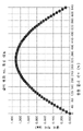
도 14는 개시된 실시예의 양태들에 따른 비원형 풀리의 주어진 회전 각도에 대해 비원형 풀리 주위를 감싸는 밴드의 길이의 차이를 예시하는 주어진 비원형 풀리에 대한 예시적인 그래프를 도시한다.
도 15는 개시된 실시예의 양태에 따른 구동 풀리 각동 대한 도 1a 내지 도 1e의 이송 장치의 트랜스미션에서 진동 주파수의 예시적인 그래프를 도시한다.
도 16은 개시된 실시예의 양태에 따른 도 1a 내지 도 1e의 이송 장치의 트랜스미션의 예시적인 밴드 구성의 개략도이다.
도 17a는 개시된 실시예의 양태에 따른 도 1a 내지 도 1e의 이송 장치의 트랜스미션의 예시적인 밴드 구성의 개략도이며, 도 17b는 언급된 바와 같은 단면도이다.
도 18a는 개시된 실시예의 양태에 따른 도 1a 내지 도 1e의 이송 장치의 트랜스미션의 예시적인 대역 구성의 개략도이다.
도 18b는 개시된 실시예의 양태에 따른 도 18a의 트랜스미션의 예시적이 밴드 구조를 포함하는 도 1a 내지 도 1e의 이송 장치의 아암 링크의 개략도이다.
도 19a 및 19b는 개시된 실시예의 양태에 따른 예시적인 밴드 설치 고정구를 도시한다.
도 20은 개시된 실시예의 양상들에 따른 예시적인 방법이다.
도 21은 개시된 실시예의 양상들에 따른 예시적인 방법이다.
도 22는 개시된 실시예의 양상들에 따른 예시적인 방법이다.The foregoing and other features of the disclosed embodiments are set forth in the following description taken in conjunction with the accompanying drawings.
1A-1E illustrate an exemplary substrate transport apparatus in accordance with aspects of the disclosed embodiment.
2A-2E illustrate exemplary substrate processing apparatus in accordance with aspects of the disclosed embodiments.
3A is a schematic diagram of a portion of the substrate transport apparatus of FIGS. 1A-1E in accordance with aspects of the disclosed embodiment.
3B is a schematic diagram of a portion of the substrate transport apparatus of FIGS. 1A-1E in accordance with aspects of the disclosed embodiment.
3C is a schematic diagram of a portion of the substrate transport apparatus of FIGS. 1A-1E in accordance with aspects of the disclosed embodiment.
3D is a schematic diagram of a portion of a substrate processing apparatus in accordance with aspects of the disclosed embodiments.
4A-4C are diagrams illustrating an example of the substrate transfer apparatus of FIGS. 1A-1E in accordance with aspects of the disclosed embodiment, and FIG. 4D is a cross-sectional view.
5A depicts a portion of an exemplary transmission of the substrate transport apparatus of FIGS. 1A-1E in accordance with aspects of the disclosed embodiment.
5B shows a cross-sectional view of a portion of the exemplary transmission of FIG. 5A in accordance with aspects of the disclosed embodiment.
6 depicts a portion of an exemplary transmission of the substrate transport apparatus of FIGS. 1A-1E in accordance with aspects of the disclosed embodiment.
7 depicts a portion of an exemplary transmission of the substrate transport apparatus of FIGS. 1A-1E in accordance with aspects of the disclosed embodiment.
8A-8C illustrate a portion of an exemplary transmission of the substrate transport apparatus of FIGS. 1A-1E in accordance with aspects of the disclosed embodiment.
9A-9B illustrate a portion of an exemplary transmission of the substrate transport apparatus of FIGS. 1A-1E in accordance with aspects of the disclosed embodiment.
10A and 10B show a portion of an exemplary transmission of the substrate transport apparatus of FIGS. 1A-1E in accordance with aspects of the disclosed embodiment.
11 illustrates a cross-sectional view of a portion of the exemplary transmission of FIGS. 9A, 9B, 10A, 1B in accordance with aspects of the disclosed embodiment.
12A depicts a portion of an exemplary transmission of the substrate transport apparatus of FIGS. 1A-1E in accordance with aspects of the disclosed embodiment.
12B and 12C show a portion of an exemplary transmission of the substrate transport apparatus of FIGS. 1A-1E in accordance with aspects of the disclosed embodiment.
13A and 13B schematically illustrate opposing band wraps of upper and lower pulley portions of an exemplary transmission of the substrate transport apparatus of FIGS. 1A-1E in accordance with aspects of the disclosed embodiments.
14 shows an example graph for a given non-circular pulley illustrating the difference in length of a band wrapped around a non-circular pulley for a given angle of rotation of the non-circular pulley in accordance with aspects of the disclosed embodiment.
15 shows an exemplary graph of vibration frequency in the transmission of the conveying device of FIGS. 1A-1E versus drive pulley angular motion in accordance with aspects of the disclosed embodiment.
16 is a schematic diagram of an exemplary band configuration of the transmission of the transport apparatus of FIGS. 1A-1E in accordance with aspects of the disclosed embodiment;
17A is a schematic diagram of an exemplary band configuration of the transmission of the transport apparatus of FIGS. 1A-1E in accordance with aspects of the disclosed embodiment, and FIG. 17B is a cross-sectional view as noted.
18A is a schematic diagram of an exemplary band configuration of the transmission of the transport apparatus of FIGS. 1A-1E in accordance with aspects of the disclosed embodiment;
18B is a schematic diagram of an arm link of the transport device of FIGS. 1A-1E including an exemplary band structure of the transmission of FIG. 18A in accordance with aspects of the disclosed embodiment;
19A and 19B illustrate exemplary band installation fixtures in accordance with aspects of the disclosed embodiments.
20 is an exemplary method in accordance with aspects of the disclosed embodiment.
21 is an exemplary method in accordance with aspects of the disclosed embodiment.
22 is an exemplary method in accordance with aspects of the disclosed embodiment.
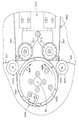
도 1a 내지 도 2e를 참조하면, 여기에 추가로 개시된 바와 같이, 개시된 실시예의 양태를 통합하는 기판 처리 장치 또는 도구의 개략도가 도시되어 있다. 개시된 실시예의 양태가 도면을 참조하여 설명될 것이지만, 개시된 실시예의 양태는 많은 형태로 구현될 수 있다는 것이 이해되어야 한다. 또한, 임의의 적절한 크기, 모양 또는 유형의 요소 또는 재료가 사용될 수 있다.1A-2E , there is shown a schematic diagram of a substrate processing apparatus or tool incorporating aspects of the disclosed embodiments, as further disclosed herein. While aspects of the disclosed embodiments will be described with reference to the drawings, it should be understood that aspects of the disclosed embodiments may be embodied in many forms. Also, any suitable size, shape, or type of element or material may be used.
본원에 설명된 개시된 실시예의 양태는 로봇 매니퓰레이터를 위한 밴드 및 풀리 토크 트랜스미션 구동 구성을 제공한다. 일반적으로 반도체 처리 산업에서는 반도체 처리 장치(즉, 이러한 처리 장치를 고밀도 처리 모듈 도구라고 부를 수 있음)에서 처리 모듈의 수를 증가시키려는 요구가 있다. 증가된 수의 도구에 대하여 기판을 이송하기 위해, 기판 이송 장치는 증가된 도달 요구 사항을 충족해야 한다. 여기에 제공된 개시된 실시예의 양태는 고밀도 처리 모듈 도구의 임의의 처리 모듈로의 기판 이송을 용이하게 하는 아암 이동을 제공하기 위해 증가된 조인트 각도 회전(위에서 설명된 종래의 이송 아암과 비교하여)을 제공한다. 증가된 조인트 각도 회전은, 예를 들어, 입력(예: 구동) 풀리와 출력(예: 종동) 풀리 사이의 구동(또는 감소) 비율(여기서 구동 비율은 종동 풀리의 직경에 대한 구동 풀리의 직경 사이의 비율임)에 의해 정의되는 회전 각 (RR)에 의해 구동 및/또는 종동 풀리의 회전에 대하여 제공하는 개시된 실시예의 양태의 밴드 및 풀리 토크 트랜스미션 구동 구성에 의해 행해진다. 개시된 실시예의 일 양태에서, 구동 풀리의 회전은 약 320°의 회전일 수 있다(예를 들어, 여기에 설명된 중간 스트로크 위치로부터 약 +/- 160°). 구동 풀리가 약 320° 회전하고 구동 풀리와 종동 풀리 사이의 비율이 2:1인 경우, 종동 풀리는 최대 약 640°(예: 중간 스트로크에서 약 +/- 320°)까지 회전할 수 있다. 구동 풀리와 종동 풀리 간에 3:1 비율이 사용되는 경우, 종동 풀리는 최대 약 960°(예: 중간 스트로크에서 약 +/- 480°)까지 회전할 수 있다. 종동 풀리의 약 360°보다 큰 회전은 예를 들어 로봇 매니퓰레이터의 관절 링크에서 증가된 스트로크로 인해 증가된 로봇 매니퓰레이터 동작 범위를 제공한다.Aspects of the disclosed embodiments described herein provide a band and pulley torque transmission drive configuration for a robotic manipulator. In general, there is a desire in the semiconductor processing industry to increase the number of processing modules in a semiconductor processing apparatus (ie, such processing apparatus may be referred to as a high-density processing module tool). In order to transfer substrates for an increased number of tools, the substrate transfer apparatus must meet increased reach requirements. Aspects of the disclosed embodiments provided herein provide increased joint angular rotation (as compared to the conventional transfer arms described above) to provide arm movement that facilitates substrate transfer to any processing module of a high density processing module tool. do. The increased joint angular rotation can be, for example, the actuation (or decreasing) ratio between the input (e.g. drive) pulley and the output (e.g. driven) pulley, where the actuation ratio is between the diameter of the driven pulley to the diameter of the driven pulley. The band and pulley torque transmission drive configuration of aspects of the disclosed embodiment provides for rotation of the driven and/or driven pulley by an angle of rotation RR defined by In one aspect of the disclosed embodiment, the rotation of the drive pulley may be about 320° of rotation (eg, about +/- 160° from the mid-stroke position described herein). If the drive pulley rotates about 320° and the ratio between the drive pulley and the driven pulley is 2:1, then the driven pulley can rotate up to about 640° (eg, about +/- 320° at mid stroke). If a 3:1 ratio is used between the drive pulley and the driven pulley, the driven pulley can rotate up to about 960° (eg about +/- 480° on mid stroke). A rotation of greater than about 360° of the driven pulley provides an increased range of motion for the robot manipulator due to, for example, increased stroke in the articulation link of the robot manipulator.
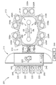
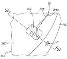
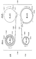
도 1a 내지 도 1e를 참고하면, 예시적인 기판 이송 장치(100 내지 104)가 도시되고 이하에서 더 상세히 설명될 것이다. 각각의 기판 이송 장치(100-104)는 일반적으로 프레임(110F), 상기 프레임(110F)에 연결된 구동 섹션(110), 및 구동 섹션(110)에 작동가능하게 연결된 적어도 하나의 관절 아암 링크(예를 들어, 상부 아암 링크(130) 또는 상부 아암 링크(130) 및 전방 아암 링크(131))를 구비하는 관절 아암(예를 들어 이송 아암(120-124)와 같은 이송 아암으로서도 언급됨)을 포함하여, 상기 관절 아암은 상기 프레임(110F)에 대하여 피벗 축(예를 들어, 어깨 축 (SX))을 중심으로 회전하고 상기 피벗 축(어깨 축(SX))에 대하여 연장 및 후퇴한다. 여기에서 더 자세히 설명되는 바와 같이, 상기 이송 아암은 엔드이펙터(140, 140a, 140b, 141, 142)와 배치된 아암 조인트 피벗 축(예를 들어 손목 조인트(WX))를 구비한 적어도 하나의 관절 아암 링크 사이에 조인트(예를 들어, 손목 조인트(336) - 도 3a 참고)를 형성하는 적어도 하나의 관절 아암 링크에 피벗가능하게 연결된 엔드이펙터(140, 140a, 140b, 141, 142)를 구비하여, 상기 엔드이펙터(140, 140a, 140b, 141, 142)는 손목 축(WX)에 대하여 적어도 하나의 관절 아암 링크에 대하여 회전하게 된다. 1A-1E , exemplary substrate transport apparatuses 100-104 are shown and will be described in greater detail below. Each substrate transport apparatus 100-104 generally includes a
이송 아암(120-124)이 SCARA 아암 구성을 갖는 것으로 여기에서 설명되지만, 다른 측면에서 이송 아암은 임의의 적합한 구성을 가질 수 있다. 도 1a를 참조하면, 사익 기판 이송 장치(100)는 이송 아암(120) 및 구동 섹션(110)을 포함한다. 상기 이송 아암(120)은 (여기에서 설명되는 바와 같이) 구동 섹션(110)의 출력부에 결합되고, 어깨 회전축(SX)에서 구동 섹션(130)에 회전 가능하게 결합된 상부 아암 링크(130), 엘보우 회전축(EX)에서 상부 아암 링크(130)에 회전가능하게 연결된 전측 아암 링크(131), 및 손목 회전축(WX)에서 전측 아암 링크(131)에 회전 가능하게 결합된 적어도 하나의 단일 단부 엔드이펙터(예를 들어, 기판 홀더)(140)를 포함한다. 상기 엔드이펙터(140)는 손목 축(WX)의 단일 측면에 배치된 단일 기판 홀딩 위치(140H)를 포함한다. 다른 실시예에서, 상기 엔드이펙터(140)는 손목 축(WX)의 단일 측면 상에 실질적으로 동일한 평면에서 나란히 배열되거나 다른 것 위에 적층된 하나 이상의 기판 홀딩 위치를 포함할 수 있다. 일 실시예에서, 상기 엔드이펙터(140)의 회전은 예를 들어 상부 아암 링크(130)에 종속될 수 있어, 상기 엔드이펙터(140)는 이송 장치(100)의 신장 및 후퇴 축과 정렬된 상태를 유지한다. 다른 실시예에서, 상기 엔드이펙터(140)는 구동 섹션(110)의 각각의 구동 모터에 결합되어, 손목 축(WX)에 대한 엔드이펙터(140)의 회전이 상부 아암 링크(130) 및 전측 아암 링크(131)의 이동에 대하여 독립적이다(비록 회전이 이러한 이동에 조정된다고 하더라도).Although transfer arms 120 - 124 are described herein as having a SCARA arm configuration, in other aspects the transfer arms may have any suitable configuration. Referring to FIG. 1A , the wing
이제 도 1b를 참조하면, 상기 기판 이송 장치(101)는 이송 장치(100)와 실질적으로 유사하다. 그러나, 이 실시예에서, 상기 이송 아암(101)은 적어도 2개의 대향하는 기판 홀딩 위치(140H1, 140H2)(예를 들어, 이중 팬)를 갖는 적어도 하나의 이중 팬 엔드이펙터(141)를 포함한다. 예를 들어, 상기 엔드이펙터(141)는 손목 축(WX)의 대향하는 측 상에서 연장되어, 엔드이펙터(141)의 각각의 대향 단부(141E1, 141E2)는 적어도 하나의 개별 기판 홀딩 위치(들)(140H1, 140H2)(예를 들어, 기판 홀딩 위치(140H1, 140H2)는 손목 축(WX)을 직경 방향으로 가로질러 정반대이다)을 구비한다. 이 예에서, 상기 엔드이펙터(141)는 단부(141E1, 141E2)(여기서 손목 축(WX)이 단부(141E1, 141E2) 사이에 배치됨) 사이에 관절이 형성되지 않은 실질적으로 경질인 엔드이펙터로서 도시된다. 단일의 기판 홀딩 스테이션(140H1, 140H2)이 단지 설명의 목적을 위해 각 단부(141E1, 141E2)에 도시되어 있지만, 다른 실시예에서, 하나 이상의 단부(141E1, 141E2)는 서로 적층되어 배치되거나 실질적으로 동일한 평면에 나란히 배열된 하나 이상의 기판 홀딩 스테이션을 구비한다. 일 실시예에서, 상기 엔드이펙터(141)의 회전은 예를 들어 상부 아암 링크(130)에 종속될 수 있어서, 상기 엔드이펙터(141)는 이송부(100)의 신장 및 후퇴 축과 정렬된 상태를 유지한다. 다른 실시예에서, 상기 엔드이펙터(141)는 구동 섹션(110)의 각각의 구동 모터에 결합되어 손목 축(WX)을 중심으로 한 엔드이펙터(141)의 회전이 상부 아암 링크(130) 및 전측 아암 링크(131)의 움직임(회전이 조정될 수 있지만)과 독립적일 수 있다.Referring now to FIG. 1B , the
도 1c를 참조하면, 상기 기판 이송 장치(101)는 이송 장치(100)와 실질적으로 유사하다. 그러나, 이 실시예에서, 상기 이송 아암(102)은 2개의 단일 단부 엔드이펙터(140A, 140B)를 포함한다. 각각의 단일의 단부 엔드이펙터(140A, 140B)는 위에서 설명된 엔드이펙터(140)와 실질적으로 유사하다. 다른 실시예에서, 상기 이송 아암(102)은 2개의 이중 팬 엔드이펙터를 포함할 수 있고, 여기서 이중 팬 엔드이펙터의 각각은 위에서 설명된 실질적으로 유사한 이중 팬 엔드이펙터(141)이다. 일 실시예에서, 엔드이펙터(140A, 140B) 각각은 다른 엔드이펙터(140A, 140B)에 대해 손목 축(WX)을 중심으로 독립적으로 회전 가능하며, 여기서 각각의 엔드이펙터는 구동 섹션(110)의 각각의 구동 모터에 결합된다. 다른 실시예에서, 하나의 엔드이펙터(140A, 140B)가 회전할 다른 엔드이펙터(140A, 140B)가 동일한 회전 속력으로 속목 축(WX)을 중심으로 반대 방향으로 회전하도록, 엔드이펙터(140A, 140B)는 임의의 적절한 방식으로 구동 섹션의 공통 구동 모터에 차동적으로 결합될 수 있다.Referring to FIG. 1C , the
도 1d를 참조하면, 이 실시예에서, 상기 이송 아암(123)은 구동 섹션(110)에 회전 가능하게 결합된 상부 아암 링크(130), 및 임의의 중간 아암 링크 없이 상부 아암 링크(130)에 회전 가능하게 결합된 적어도 하나의 엔드이펙터(140A, 140B)를 포함한다 (즉, 적어도 하나의 엔드이펙터(140A, 140B)는 상부 아암 링크(130)에 직접 결합된다). 이 예에서, 상기 상부 아암 링크(130)는 어깨 축(SX)과 손목 축(WX) 사이의 실질적으로 관절이 없는 링크이다. 적어도 하나의 엔드이펙터(140A, 140B) 각각은 위에서 설명된 엔드이펙터(140, 140A, 140B)와 실질적으로 유사할 수 있다. 2개의 단일의 단부 엔드이펙터(140A, 140B)가 예시 목적으로만 도시되어 있지만, 다른 실시예에서, 상기 이송 아암(123)은 단 하나의 단일의 단부 엔드이펙터(140)를 가질 수 있다. 또 다른 실시예에서, 상기 기판 이송 아암(123)은 위에서 설명된 이중 팬 엔드이펙터(141)와 실질적으로 유사한 하나 이상의 이중 팬 엔드이펙터를 포함할 수 있다. 여기서 각각의 엔드이펙터는 (예를 들어, 구동 섹션의 각각의 구동 모터에 의해) 상부 아암 링크(130)에 대해 독립적으로 회전가능할 수 있다.Referring to FIG. 1D , in this embodiment, the
도 1e를 참조하면, 상기 기판 이송 장치(104)는 이송 아암(120)과 실질적으로 유사한 이송 아암(124)을 포함하지만, 이 실시예에서 이송 아암(120)은 적어도 하나의 사이드-바이-사이드(side-by-side) 팬 엔드이펙터(142)를 포함한다. 이 예에서, 사이드-바이-사이드 팬 엔드이펙터(142)는 2개의 사이드-바이-사이드(예를 들어, 이중 팬) 기판 홀딩 위치(140S1, 140S2)를 포함하지만, 다른 실시예에서 2개 이상의 사이드-바이-사이드 기판 홀딩 위치가 있게 된다. 위에서 언급한 바와 같이, 사이드-바이-사이드 기판 홀딩 위치는 실질적으로 동일한 평면에 위치한다. 상기 사이드-바이-사이드 기판 홀딩 위치(140S1, 140S1)는 여기에 설명되는 바와 같이 사이드-바이-사이드 기판 홀딩 스테이션에 대하여실질적으로 동시에 기판을 선택하고 배치하기 위해 제공된다.Referring to FIG. 1E , the
도 1a 내지 도 2e를 참조하면, 예를 들어 반도체 툴 스테이션(200-203)과 같은 처리 장치가 개시된 실시예의 양태에 따라 도시된다. 반도체 툴 스테이션이 도면에 도시되어 있지만, 여기에 설명된 개시된 실시예의 양태는 로봇 매니퓰레이터를 사용하는 임의의 툴 스테이션 또는 애플리케이션에 적용될 수 있다. 도시된 예에서, 툴 스테이션(200, 202, 203)은 클러스터 툴로서 도시되어 있지만, 개시된 실시예의 양태는 예를 들어 2013년 3월 13일자로 발행된 "선형 분포 반도체 공작물 처리 툴"이라는 명칭의 미국 특허 ,398,35호 및 2011년 3월 8일자로 발생된 "기판을 이동 및 처리하기 위한 장치 및 방법" 이라는 명칭의 미국 특허 7,901,539호에 설명된 선형 툴 스테이션과 같은 임의의 적절한 툴 스테이션에 적용될 수 있으며, 위 미국 특허는 본원에 그 전체가 참고로 편입된다. 상기 툴 스테이션(200-203)은 일반적으로 대기 전단부(211), 진공 로드 록(212), 및 진공 후단부(213)를 포함한다. 다른 실시예에서, 툴 스테이션은 임의의 적절한 구성을 가질 수 있다. 전단부(211), 로드 록(212), 및 후단부(213)의 각각의 구성요소는 예를 들어 클러스터링된 아키텍처 제어와 같은 임의의 적절한 제어 아키텍처의 일부일 수 있는 콘트롤러(299)에 연결될 수 있다. 제어 시스템은 2011년 3월 8일자로 발행된 "스케일 가능한 모션 제어 시스템" 이라는 제목의 미국 특허 번호 7,904,182호에 개시된 것과 같은 마스터 콘트롤러, 클러스터 콘트롤러 및 자율 원격 콘트롤러를 갖는 폐쇄 루프 콘트롤러일 수 있으며, 그 개시 내용은 본원에 참조로 편입된다. 다른 실시예에서, 임의의 적절한 제어기 및/또는 제어 시스템이 이용될 수 있다.1A-2E , a processing apparatus, such as, for example, a semiconductor tool station 200 - 203 , is illustrated in accordance with aspects of the disclosed embodiment. Although a semiconductor tool station is shown in the figures, aspects of the disclosed embodiments described herein may be applied to any tool station or application using a robotic manipulator. In the illustrated example, the
도 2a를 참조하면, 일 실시예에서, 전단부(211)는 일반적으로 로드 포트 모듈(220) 및 예를 들어 장비 전단부 모듈(EFEM)과 같은 미니 환경(221)을 포함한다. 상기 로드 포트 모듈(220)은 300mm 로드 포트에 대한 SEMI 표준 E15.1, E47.1, E62, E19.5 또는 E1.9, 450mm 로드 포트, 전방 개구 또는 바닥 개구 박스/팟 및 카세트에 대한 SEMI 표준을 준수하는 툴 표준에 대한 박스 오프너/로더(BOLTS: box opener/loader to tool standard) 인터페이스일 수 있다. 다른 실시예에서, 상기 로드 포트 모듈(220)은 200mm, 300mm, 및/또는 450mm 기판 또는 웨이퍼 인터페이스 또는 예를 들어 평판 디스플레이용 더 크거나 작은 기판 또는 평면 패널과 같은 임의의 다른 적절한 기판 인터페이스로 구성될 수 있다. 3개의 로드 포트 모듈이 도면 3에 표시되어 있지만. 도 2a에 도시된 바와 같이, 다른 실시예에서, 임의의 적절한 수의 로드 포트 모듈이 전단부(211)에 통합될 수 있다. 상기 로드 포트 모듈(220)은 오버헤드 이송 시스템, 자동 안내 차량, 사람 안내 차량, 레일 안내 차량 또는 임의의 다른 적절한 이송 방법으로부터 기판 캐리어 또는 카세트(250)를 수용하도록 구성될 수 있다. 상기 로드 포트 모듈(220)은 로드 포트(240)를 통해 미니 환경(221)과 인터페이싱할 수 있다. 상기 로드 포트(240)는 기판 카세트(250)와 미니 환경(221) 사이에서 기판의 통과를 허용할 수 있다. 상기 미니 환경(221)은 일반적으로 여기에 설명된 개시된 실시예의 하나 이상의 양태를 통합할 수 있는 임의의 적절한 대기 이송 로봇(222)을 포함한다. 일 실시예에서, 상기 로봇(222)은 예를 들어 그 개시 내용이 본 명세서에 전체적으로 참조로 포함되는 미국 특허 번호 6,002,840호에 설명된 것과 같은 트랙 장착 로봇일 수 있다. 상기 미니 환경(221)은 다중 로드 포트 모듈 사이의 기판 전달을 위한 제어된 청정 구역을 제공할 수 있다.Referring to FIG. 2A , in one embodiment, the
상기 진공 로드 록(212)은 미니 환경(221)과 후단부(213) 사이에 위치하여 연결될 수 있다. 본 명세서에 사용된 바와 같은 진공이라는 용어는 기판이 처리되는 10-5 Torr 이하와 같은 고진공을 나타낸다. 상기 로드 록(212)은 일반적으로 대기 및 진공 슬롯 밸브를 포함한다. 상기 슬롯 밸브는 대기 전단부에서 기판을 로드한 후 로드 록을 비우고 질소와 같은 불활성 가스로 록을 배출할 때 이송 챔버의 진공을 유지하는 데 사용되는 환경 격리를 제공할 수 있다. 상기 로드 록(11010)(또는 미니 환경(221))은 또한 기판의 기준을 프로세싱을 위한 원하는 위치에 정렬하기 위한 정렬기를 포함할 수 있다. 다른 실시예에서, 상기 진공 로드 록은 처리 장치의 임의의 적절한 위치에 위치될 수 있고 임의의 적절한 구성을 가질 수 있다.The
진공 후단부(213)는 일반적으로 이송 챔버(214), 하나 이상의 탄뎀(tandem) 처리 스테이션(230)(예를 들어, 공통 하우징에 배치된 적어도 2개의 기판 홀딩 스테이션을 갖는 처리 스테이션) 및 본 명세서에 기술된 개시된 실시예의 하나 이상의 측면을 포함하는 임의의 적절한 진공 이송 로봇(280)을 포함한다. 상기 이송 로봇(280)은 로드 록(212)과 다양한 처리 스테이션(230) 사이에서 기판을 이송하기 위해 이송 챔버(214) 내에 위치될 수 있다. 상기 처리 스테이션(230)은 기판 상에 전기 회로 또는 다른 원하는 구조를 형성하기 위해 다양한 증착, 에칭, 또는 다른 유형의 공정을 통해 기판 상에서 동작할 수 있다. 일반적인 공정에는 플라즈마 에칭 또는 기타 에칭 공정, 화학 기상 증착(CVD), 플라즈마 기상 증착(PVD), 이온 주입과 같은 주입, 계측, 급속 열 처리(RTP), 건식 스트립 원자층 증착(ALD), 산화/확산, 질화물 형성, 진공 리소그래피, 에피택시(EPI), 와이어 본더 및 증발 또는 진공 압력을 사용하는 기타 박막 공정과 같은 진공을 사용하는 박막 공정을 포함하지만 이에 한정되지는 않는다. 상기 처리 스테이션(230)은 기판들이 이송 챔버(214)로부터 처리 스테이션(230)로 또는 그 반대로 통과될 수 있도록 이송 챔버(214)에 연결된다. 이 실시예에서, 상기 처리 스테이션(230)은 각각 2개의 사이드-바이-사이드 기판 홀딩 스테이션들을 갖는 것으로 예시되어 있지만, 도 2b에 예시된 것과 같은 다른 실시예들에서, 상기 처리 스테이션(230A)은 처리 스테이션(230A)은 나란히 배열되는 단일 기판 홀딩 스테이션을 가질 수 있다.The
여전히 도 2a를 참조하면, 그리고 위에서 설명된 바와 같이, 상기 이송 챔버(214)는 대향하는 처리 스테이션(230)의 2개의 행을 형성하기 위해 각각의 측면을 따라 배열된 3개의 처리 스테이션(230)을 갖는 길이방향으로 연장된 직사각형 구성을 갖는다(다른 실시예에서는 더 또는 3개 미만의 처리 스테이션이 측면 각각에 배치될 수 있음). 상기 기판 이송 장치(100)는 단지 예시적인 목적을 위해 도 2a의 이송 챔버(214)(예를 들어, 구동 하우징(322)의 일부가 이송 챔버(214)의 밀봉된 분위기 외부에 위치될 수 있음) 내에 적어도 부분적으로 도시되어 있고, 이송 챔버(214)는 이송 장치(100-104) 중 어느 하나를 포함한다. 예로서, 도 2e는 내부에 적어도 부분적으로 배치된 이송 장치(104)를 갖는 이송 챔버(214)를 도시한다.Still referring to FIG. 2A , and as described above, the
도 2b에 도시된 것과 같은 다른 실시예에서, 상기 이송 챔버(214A)(이는 이송 챔버(214)와 실질적으로 유사함)는 이송 챔버의 각 면이 이에 연결된 2개의 기판 홀딩 스테이션(로드 록(212)을 포함)을 구비하는 다중-면 6-변 구조체를 가진다. 위에서 언급한 바와 같이, 그리고 도 2b에 예시된 바와 같이, 상기 처리 스테이션(230)은 각각 내부에 단일 기판 홀딩 스테이션을 갖고 이송 챔버(214)의 다른 면에 쌍으로 배열된다. 다른 실시예에서, 2개의 기판 홀딩 스테이션을 갖는 처리 스테이션(230)(도 2a에 도시된 것과 같은)은 도 2b의 이송 챔버(214)의 상이한 면 상에 배치될 수 있다. 상기 기판 이송 장치(101)는 단지 예시적인 목적을 위해 도 2b의 이송 챔버(214A) 내에 적어도 부분적으로 도시되어 있으며, 이송 챔버는 이송 장치(100-104) 중 어느 하나를 포함할 수 있다.In another embodiment, such as that shown in FIG. 2B , the
도 2c를 참조하면, 도 2a의 수송 챔버(214)와 유사한 수송 챔버(214B)가 도시되어 있다. 그러나, 이송 챔버(214B)는 로드 록(들)(212) 반대편에 있는 이송 챔버(214B)의 길이방향 단부에 처리 스테이션(230)을 포함한다. 실현될 수 있는 바와 같이, 탄뎀 단일 처리 스테이션(230) 중 임의의 하나는 도 2b의 처리 스테이션(230A) 중 2개로 대체될 수 있다. 상기 기판 이송 장치(102)는 단지 예시적인 목적을 위해 도 2c의 이송 챔버(214B) 내에 적어도 부분적으로 도시되어 있으며, 이송 챔버(214B)는 이송 장치(100-104) 중 어느 하나를 포함할 수 있다.Referring to FIG. 2C , a
도 2d를 참조하면, 도 2a의 이송 챔버(214)와 실질적으로 유사한 이송 챔버(214C)가 도시되지만, 상기 이송 챔버(214C)는 2개의 기판 홀딩 스테이션이 이송 챔버(214C)의 4개의 측면 각각에 결합될 수 있는 실질적으로 정사각형 구성을 갖는다. 도 2d에 도시된 예에서, 상기 처리 스테이션들(230) 및 처리 스테이션들(230A) 모두는 이송 챔버(214C)의 각각의 측면들에 결합된다. 여기서, 로드록(들)(212) 반대편에 있는 이송 챔버(214C)의 측면에 처리 스테이션을 연결하는 대신, 다른 로드록(들)(212A)이 이송 챔버(214C)에 연결되어, 이송 챔버(214C)는 이송 챔버(214, 214A, 214B, 214C) 중 어느 하나와 실질적으로 유사할 수 있는 다른 이송 챔버(214X)에 다른 로드록(214C)에 통신 가능하게 연결될 수 있다. 이러한 방식으로, 기판 처리 툴(203)은 임의의 적절한 수의 이송 챔버 및 처리 스테이션을 포함하도록 선형으로 연장될 수 있다. 상기 기판 이송 장치(103)는 단지 예시적인 목적을 위해 도 2d의 이송 챔버(214C) 내에 적어도 부분적으로 도시되어 있으며, 이송 챔버는 이송 장치(100-104) 중 어느 하나를 포함할 수 있다.2D, there is shown a
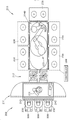
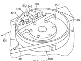
도 3a 및 도 3b를 참조하면, 기판 이송 장치(320)가 도시된다. 상기 기판 이송 장치(320)는 일반적으로 위에서 설명된 기판 이송 장치(100-104)(및 이송 장치(222)) 각각을 나타낸다. 실현될 수 있는 바와 같이, 위에서 설명된 로봇 이송 장치(100-104, 222) 각각은 적어도 하나의 토크 트랜스미션 밴드에 의해 구동되는 적어도 하나의 아암 링크를 포함할 수 있다. 예를 들어, 상기 이송 아암(120-124)은 소정의 감속비를 갖는 구동 및 아이들러 풀리(342, 344)를 갖는 구동 밴드 트랜스미션(390), 및 신장되고 신장(399) 또는 후퇴(398)의 엔드이펙터 스트로크를 통해 각각 엔드이펙터(140, 140A, 140B, 141, 142)를 이동시키는 이송 아암(120-124)을 신장 및 후퇴시키는 구동 및 아이들러 풀리(342, 344)를 연결하는 적어도 하나의 밴드(350, 351)를 구비한다. 각각의 신장 행정(399) 및 후퇴 행정(389)은 이송 아암(120-124)을 연장 또는 후퇴하고 엔드이펙터(140, 140A, 140B, 141, 142)를 대응하는 엔드이펙터 행정(예를 들어, 도 2a에 예시됨)을 통하여 이동시키는 아암 운동 스트로크를 나타낸다. 아래에 더 상세히 설명되는 바와 같이, 적어도 하나의 밴드(350, 351)는 풀리(342, 344) 중 적어도 하나 주위에 감겨져서(풀리에 적어도 하나의 밴드(350, 351)가 연결되어, 즉 연결된 풀리), 적어도 하나의 밴드(350, 351)는 그 자체에 대해(또는 그 위에) 오버랩되어(예를 들어, 도 4b, 4c, 7, 9b, 10c, 13, 16 참조), 이러한 전달은 적어도 하나의 관절 아암 링크(예를 들어, 상부 아암 링크(326) 또는 전측 아암 링크(328)에 대하여, 엔드이펙터의 엔드이펙터 중간 스트로크 회전 위치(MID: 도 2a)로부터 엔드이펙터의 최대 스트로크 회전 위치(MAX: 도 2a) 까지의 약 +/- 180°를 넘는 손목 축(WX)을 중심으로 엔드이펙터(140, 140a, 140b, 141, 142)의 회전을 발생시키게 된다. 일 실시예에서, 최대 신장 스트로크(예: 최대 스트로크 회전 위치 MAX - 도 2A)와 최대 후퇴 스트로크 MAXR: 도 2A) 사이에서 엔드이펙터(140, 140A, 140B, 141, 142)의 회전(RR)은 적어도 약 +/- 300°(및 일부 측면에서 약 +/- 360° 초과)이다.3A and 3B , a
도 3a 및 도 3b에 도시된 바와 같이, 여기에 설명된 것과 같은 로봇 이송 장치에서 사용하기 위한 예시적인 토크 트랜스미션 밴드 구성은 본 명세서에 설명된 이소 장치 중 임의의 하나를 나타내는 로봇 이송 장치(320)에 대한 개시된 실시예의 양태에 따라 도시된다. 도 3a 및 도 3b에 도시된 바와 같이, 로봇 이송 장치(320)는 임의의 적절한 프레임(110F)에 장착된 이송 아암(324)을 포함하며, 이는 일 실시예에서 구동 하우징(322)을 형성하는 반면, 다른 실시예에서 드라이브 하우징(322)은 임의의 적절한 방식으로 프레임(110F)에 결합된다. 일 실시예에서, 상기 이송 아암(324)은 SCARA 아암일 수 있고, 근위 및 원위 단부를 갖는 상부 아암(326), 근위 및 원위 단부를 갖는 전측 아암(328), 및 그 위에 하나 이상의 기판을 유지하도록 구성된 적어도 하나의 기판 지지체 또는 엔드이펙터(330)를 포함할 수 있다. 상기 상부 아암(326)의 근위 단부는 어깨 조인트(332)에서 베이스(322)에 회전 가능하게 연결된다. 전측 아암(328)의 근위 단부는 엘보우 조인트(334)에서 상부 아암(326)의 원위 단부에 회전 가능하게 연결된다. 하나 이상의 기판 지지부(330)는 손목 관절(336)에서 전측 아암(328)의 말단부에 회전 가능하게 연결될 수 있다. 여기에 예시된 SCARA 아암에 추가하여, 개시된 실시예의 양태와 함께 사용될 수 있는 아암 구성의 다른 예에는 그 전체가 본 명세서에 참고적으로 편입되는 2008년 5월 8일에 출원된 "기계적 스위치 기구를 사용하는 다중 이동식 아암을 가진 기판 이송 장치" 라는 제목의 미국 특허출원 12/117,415호 및 2013년 2월 11일에 출원된 "기판 처리 장치"라는 제목의 국제 특허출원 번호 PCT/US13/25513호에 설명된 아암 구성, 및 2019년 12월 2일에 출원되고 제목이 "기판 처리 장치"인 미국 특허 가출원 번호 62/942,544에 기술된 "이중 요(yaw)" 또는 볼트 및/또는 밴드가 구동 섹션(예를 들어, 샤프트 구조체를 구동하는 사이드-바이-사이드 모터)의 내부에 및/또는 아암 링크의 내부에 있는지와 무관하게 이송 아암의 작동을 위하여 하나의 풀리로부터 다른 풀리로 토크를 전달하기 위한 볼트 및/또는 밴드를 사용하는 임의의 다른 적절한 이송 아암을 포함하지만 이에 한정되지는 않는다. 개시된 실시예의 양태가 적용될 수 있는 토크 트랜스미션 밴드의 적합한 예는, 그 전체가 본 명세서에 참고로 편입되는, 2014년 8월 26일에 출원되고 "기판 이송 장치" 라는 제목으로 된 미국 특허 출원 번호 14/469,260호 및 1998년 7월 14일에 출원되고 "금속 밴드를 사용하는 로봇 조인트"라는 제목의 미국 특허 번호 5,778,730호, 1997년 11월 4일에 발행되고 "금속 밴드를 사용하는 로봇 관절" 이라는 제목의 미국 특허 번호 5,682,795호에 기술되어 있는 것들을 포함한다.3A and 3B, an exemplary torque transmission band configuration for use in a robotic transport device such as that described herein is a
구동 하우징(322)은 각각의 구동 샤프트를 구동하도록 구성된 하나 이상의 서보 또는 모터(370M, 371M)를 포함할 수 있다. 이송 구동 하우징(322)은 전술한 것과 같은 임의의 적절한 대기 또는 진공 로봇 이송에 채용될 수 있다. 상기 구동 섹션(110)은 내부에 적어도 부분적으로 배치된 적어도 하나의 구동 샤프트(339, 340)를 갖는 구동 하우징(322)을 포함할 수 있다. 2개 이상의 구동 샤프트가 있는 경우에 실현될 수 있는 바와 같이, 상기 구동 샤프트는 동축 또는 나란한 배열과 같은 임의의 적절한 배열을 가질 수 있다. 2개의 구동 샤프트(339, 340)가 다른 실시예에서 도 3a에 도시되어 있지만, 상기 구동 섹션(110)은 임의의 적절한 수의 구동 샤프트를 포함할 수 있다. 구동 샤프트(339, 340)는, 그 전체가 본 명세서에 참고로 편입되는, 2012년 10월 9일에 발행된 "자기 스핀들 베어링이 있는 로봇 구동부" 라는 제목의 미국 특허 번호 8,283,813호, 및 2011년 8월 30일에 발행된 "챔버 벽에 통합된 모터가 있는 기판 처리 장치" 라는 제목의 미국 특허 번호 8,008,884호에 설명된 것과 같은 임의의 적절한 방식으로 구동 하우징(322) 내에서 기계적으로 지지되거나 자기적으로 현수될 수 있다(예를 들어, 실질적으로 접촉 없이). 구동 섹션(110)의 각각의 구동 샤프트(339, 340)는 각각의 모터(370M, 371M)에 의해 구동될 수 있으며, 여기서 각각의 모터는 고정자(STAT) 및 회전자(ROT)를 포함한다. 여기에 설명된 구동 모터는 영구 자석 모터, 가변 자기 저항 모터(대응하는 코일 유닛을 갖는 적어도 하나의 돌출 극 및 자기 투과성 재료의 적어도 하나의 돌출 극을 갖는 적어도 하나의 개별 회전자를 가짐), 또는 임의의 다른 적절한 구동 모터일 수 있다. 고정자(들)는 구동 하우징(322) 내에 적어도 부분적으로 고정될 수 있고 회전자(들)는 각각의 구동 샤프트(339, 340)에 임의의 적절한 방식으로 고정될 수 있다. 일 실시예에서, 고정자(STAT)는 "외측" 또는 "비-밀폐된" 환경에 위치될 수 있는데, 이러한 환경은 이송 아암(324)이 회전자(ROT)가 밀봉된 환경 내에 위치하는 동안 적절한 격리 벽 또는 장벽의 사용을 통해 작동하는 분위기로부터 밀폐되어 있다(이송 아암이 작동하는 분위기는 진공 또는 기타 적절한 환경일 수 있는 "밀폐된" 환경으로 여기에서 언급된다). 본 명세서에 사용된 용어 "격리 벽"은 로봇 구동부 및/또는 센서(구동부와 관련된)의 이동 부품과 로봇 구동부 및/또는 센서의 해당 고정 부품 사이에 배치되는 임의의 적절한 비-자성 소재로 만들어진 벽을 지칭한다. 제1 구동 샤프트(339)는 어깨 관절(332)에 대한 상부 아암(326)의 회전을 구동하기 위한 모터(370M, 371M) 중 하나에 구동 가능하게 연결될 수 있다. 제2 구동 샤프트(340)(이 실시예에서 제1 구동 샤프트와 동심임)는 엘보우 조인트(334)에 대한 전측 아암(328)의 회전을 구동하기 위해 모터(370M, 371M) 중 다른 하나에 구동 가능하게 연결될 수 있다. 각각의 아암 링크(예를 들어, 상부 아암, 전측 아암 및/또는 엔드이펙터)를 구동하기 위한 모터(370M, 371M)는 기판 피킹 및 로봇 이송 장치(320)의 기판 배치 작업을 제어하기 위한 콘트롤러(11091)와 같은 임의의 적절한 콘트롤러에 임의의 적절한 방식으로 연결된다.Drive
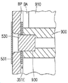
도 3a 및 도 3b에 도시된 바와 같이, 제1 풀리(342)는 예를 들어 어깨 조인트(332)에서 구동 샤프트(340)에 연결되어, 구동 샤프트(340)가 회전함에 따라 제1 풀리(342)가 구동 샤프트(340)와 함께 회전한다. 제2 풀리(344)는 예를 들어 엘보우 조인트(334)에서 샤프트(S1)에 회전 가능하게 장착될 수 있고(예를 들어, 임의의 적절한 베어링 B1을 사용하여), 샤프트(354)(상부 아암(326)에 고정됨)에 의해 임의의 적절한 방법으로 전측 아암(328)에 연결되어, 제2 풀리(344)가 회전함에 따라 전측 아암(328)이 제2 풀리(344)와 함께 회전한다. 실현될 수 있는 바와 같이, 제1 풀리 및 제2 풀리는 일 양태에서 풀리가 동일한 직경 또는 상이한 직경을 가질 수 있도록(예를 들어, 구동 풀리가 종동 풀리보다 작거나 또는 그 반대), 서로에 대하여 임의의 적절한 직경(즉 구동비)를 가진다. 또한 실현될 수 있는 바와 같이, 제1 및 제2 풀리(342, 344)는 각각 구동 풀리 및 종동 풀리일 수 있다. 제2 풀리(342)는 하나 이상의 토크 트랜스미션 밴드(350)(2개의 토크 트랜스미션 밴드(350, 351)가 도 3a 및 3b에 도시됨)와 같은 임의의 적절한 방식으로 제1 풀리(342)에 결합될 수 있다. 상기 토크 트랜스미션 밴드는 제1 풀리(342)로부터 제2 풀리(344)로 토크를 전달할 수 있는 임의의 적절한 재료로 구성될 수 있다. 일 실시예에서, 상기 토크 트랜스미션 밴드는 임의의 적절한 금속으로 구성된 금속 밴드일 수 있다. 3A and 3B , the
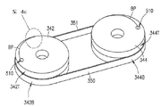
전술한 바와 같이, 상기 토크 트랜스미션 밴드(350, 351)는 각각의 토크 트랜스미션 밴드의 적어도 하나의 단부가 그 자체에 대해 오버랩되는 이중 대향 밴드를 형성하여, 예를 들어, 전술한 바와 같은 종래의 이송 아암과 비교할 때 더 큰 조인트 각도 회전에 영향을 미친다. 도 4a 내지 도 4c는 도 3a의 구동 또는 제1 풀리(342) 및 종동 또는 제2 풀리(344)에 대한 예시적인 밴드 및 풀리 구성을 도시하지만, 도 4a 내지 도 4c에 도시된 밴드 및 풀리 배열은 본 명세서에 기술된 이송 장치의 임의의 밴드 및 풀리 배열을 나타낼 수 있다. 도 4a에서 알 수 있는 바와 같이, 풀리(442, 444) 각각은 실질적으로 원형인 구성을 갖지만, 아래에 더 상세히 설명되는 바와 같은 다른 실시예에서, 풀리는 캠형 원주방향 프로파일을 가질 수 있다. 또한 실현될 수 있는 바와 같이, 상기 풀리(442, 444)는 실질적으로 1:1 구동비를 갖는 것으로 도시되어 있지만, 다른 실시예에서는 여기에 언급된 바와 같이 임의의 적절한 구동비가 제공될 수 있다. 각각의 풀리(442, 444)는 풀리 쌍을 포함할 수 있고, 상부 풀리 부분(442T, 444T) 및 하부 풀리 부분(442B, 444B)을 포함할 수 있다. 일부 실시예에서, 상부 풀리 부분(442T, 444T)은 상부 풀리 부분(442T)이 하부 풀리 부분(442B) 위에 적층되어 풀리(442)를 형성하고, 상부 풀리(444T)가 하부 풀리 부분(444B) 위에 적층되어 풀리(444)를 형성하는 각각의 하부 풀리 부분(442B, 444B) 각각으로부터 구별되고 분리되어 있다. 별개의 구별되는 상부 및 하부 풀리 부분을 갖는 것은 단일 모놀리식 풀리 주위에 각각의 대향 밴드 둘 다를 감는 것과 비교하여 각각의 풀리 부분 주위에 대향 밴드의 감는 것을 용이하게 할 수 있다. 실현될 수 있는 바와 같이, 적층된 상부 풀리 부분(442T, 444T) 및 각각의 하부 풀리 부분(442B, 444B)은 상부 풀리 부분(442T, 444T) 및 각각의 하부 풀리 부분(442B, 444B)이 하나의 유닛으로서 회전하도록 서로 결합될 수 있으며 각각의 회전축을 중심으로 단일의 모놀리식 풀리를 작동시킨다. 적층된 상부 풀리 부분(442T, 444T) 및 각각의 하부 풀리 부분(442B, 444B)은 또한 예를 들어 각각의 풀리의 레벨에서 실질적으로 반대되는 캠 프로파일을 갖는 이중 레벨 단일 모놀리식 풀리의 제조 비용과 비교하여 비원형 풀리와 같은 제조 비용을 감소시킬 수 있다.As described above, the
도 4a 내지 도 4c에 도시된 바와 같이, 토크 트랜스미션 밴드(350, 351)는 풀리(342, 344) 주위에 연속적인 원형 벨트를 형성하지 않을 수 있다. 대신에, 토크 트랜스미션 밴드(350)의 일단은 적어도 부분적으로(예를 들어, 시계 방향으로) 제1 풀리(342)에 감겨져 고정될 수 있는 반면, 토크 트랜스미션 밴드(350)의 타단부는 적어도 부분적으로 (예를 들어, 반시계 방향으로) 제2 풀리(344) 주위에 감겨서 고정된다. 상기 토크 트랜스미션 밴드(350)의 단부는 핀 또는 본 명세서에서 더 상세하게 설명되는 바와 같이 임의의 다른 적절한 제거 가능하거나 제거 불가능한 화학적 또는 기계적 패스너와 같은 임의의 적절한 방식으로 각각의 풀리(342, 344)에 고정될 수 있다. 토크 트랜스미션 밴드(350)와 실질적으로 유사한 제2 토크 트랜스미션 밴드(351)는, 토크 트랜스미션 밴드(350)에 대해 위에서 설명된 것과 실질적으로 유사한 방식으로, 그 단부에서 풀리(342, 342)에 부착될 수 있지만, 토크 트랜스미션 밴드(351)가 풀리(342, 344) 주위에 감겨지는 방향은 반전될 수 있다(예를 들어, 토크 트랜스미션 밴드(351)의 일단은 풀리(342) 주위에서 반시계 방향으로 감겨지고 토크 트랜스미션 밴드(351)의 다른 단부는 풀리(351) 주위에 시계 방향으로 감겨진다). 이러한 이중 토크 트랜스미션 밴드 구성은 양쪽 토크 트랜스미션 밴드(350, 351)를 일정한 텐션으로 두어 토크 트랜스미션 밴드가 느슨해지지 않도록 한다. 4A-4C , the
위에서 언급한 바와 같이, 각각의 토크 트랜스미션 밴드(350, 351)의 적어도 하나의 단부는 그 자체에 대해 오버랩되어, 이러한 전달이 다른 관절 아암 잉크에 대하여, 엔드이펙터(또는 다른 고나절 아암 링크)의 엔드이펙터(또는 다른 관절 아암 링크) 중간스트로크 회전 위치(MID)(도 2a)로부터 엔드이펙터(또는 다른 관절 아암 링크)의 최대 스트로크 회전 위치(MAX) 까지 약 180도를 초과하는 각각의 조인트 피벗 축을 중심으로 엔드이펙터(밴드/풀리 전달에 의해 회전 구동되는 다른 관절 아암 링크)의 회전을 발생시키게 된다. 풀리(342)와 같은 풀리에 오버랩되는 밴드(351)와 같은 밴드가 도 4b 및 4c에 도시되어 있으며 여기서 오버랩핑의 명료성을 위해 밴드 피치가 과장되게 도시되어 있다. 도 4b 및 도 4c에 도시된 바와 같이, 개시된 실시예의 일부 실시예에서, 적어도 하나의 밴드(350, 351)는 밴드 랩이 각각의 풀리 상에서 그 자체 위로 나선형으로 감겨지도록 오버랩된다. 밴드(351)(또는 여기에 설명된 임의의 다른 밴드)가 각각의 풀리에 오버랩되는 것을 용이하게 하기 위해, 밴드(351)와 풀리(342) 사이의 커플링은 풀리의 외측 주변 밴드 안착 표면(PSS)(도 4c)으로부터 도 4c에서 볼 수 있는 바와 같이 풀리의 내부로 이동하게 되고, 밴드(351)의 단부(351E)는 밴드 통로(BP)(아래에서 보다 자세하게 설명됨)를 통하여 풀리의 내부로 진입하게 된다.As mentioned above, at least one end of each
도 3a 및 도 3b를 참조하면, 기판 지지부(330)는 예를 들어 여기에 설명된 토크 트랜스미션 밴드 및 풀리 전달과 같은 임의의 적절한 트랜스미션을 사용하여 종속될 수 있으므로, 기판 지지부(330)의 종축(330X)은 로봇 아암(324)의 신장 및 수축의 축에 나란하게 유지된다. 예를 들어, 도 3b를 참조하면, 제1 풀리(342')는 샤프트(S1)에 고정될 수 있고 적어도 부분적으로 전측 아암(328)으로 연장될 수 있다. 제2 풀리(344')는 임의의 적절한 베어링(B2)을 사용하여 샤프트(S2)(전측 아암(328)에 고정될 수 있음)와 같은 손목 조인트(336)에 회전 가능하게 장착될 수 있다. 제2 풀리(344')는 제2 풀리(344')가 회전할 때 엔드이펙터(330)가 제2 풀리(344')와 함께 회전하도록 샤프트(354')와 같은 임의의 적절한 방식으로 엔드이펙터(330)에 연결될 수 있다. 토크 트랜스미션 밴드(350, 351)와 실질적으로 유사한 토크 트랜스미션 밴드(350', 351')는 제1 풀리(342')를 제2 풀리(344')에 결합하여, 전측 아암(328)과 상부 아암(326) 사이의 상대 이동이 제2 풀리의 회전을 야기하고, 이것은 다시 상부 아암 및 전측 아암에 대하여 엔드이펙터(330)를 회전시켜서, 엔드이펙터의 길이방향 축(330X)이 신장 및 수축 축과 정렬된 상태를 유지시킨다. 다른 실시예에서, 전측 아암에 대해 여기에 설명된 것과 실질적으로 유사한 방식으로, 손목 조인트(336)를 중심으로 한 기판 지지체(330)의 회전을 구동하기 위해 제3 모터 및 구동 샤프트가 로봇 이송 장치(320)에 추가될 수 있다. 3A and 3B , the
실현될 수 있는 바와 같이, 도 3a를 다시 참조하면, 기판 홀더(330)는 이중 면 엔드이펙터(예를 들어, 엔드이펙터의 회전 축 또는 손목 관절의 반대쪽에 하나 이상의 기판을 보유할 수 있는 엔드이펙터)로서 도시되어 있으며, 다른 실시예에서, 여기에 설명된 이송 아암의 기판 홀더는 예를 들어 단일 면 엔드이펙터, 배치 엔드이펙터(예를 들어, 스택 또는 옆으로 두 개 이상의 기판을 보유할 수 있음) 또는 그 임의의 조합과 같은 임의의 적절한 구성을 가질 수 있다. 또한 실현될 수 있는 바와 같이, 이송 아암(324)의 상부 아암(326) 및 전측 아암(328)은 아암 링크의 내부를 이송 아암이 작동하는 환경으로부터 밀봉하거나 그렇지 않으면 격리하기 위한 임의의 적절한 커버(C1, C2)를 가져서, 밴드와 풀리에 의해 생성된 입자는 아암 링크 외부로 전달되지 않게 된다.As may be realized, referring back to FIG. 3A , the
도 3c를 참조하면, 여기에 설명된 로봇 이송 장치의 임의의 적절한 아암 링크가 여기에 설명된 것과 같은 토크 트랜스미션 밴드에 의해 종속되고 구동될 수 있다. 예를 들어, 도 3c에 도시된 로봇 이송 장치(여기에 설명된 이송 장치 중 임의의 하나를 다시 예시하고 나타낼 수 있음)는 제1 또는 상부 아암 링크(1721) 및 상기 제1 아암 링크(1721)에 회전 가능하게 장착된 제2 또는 전측 아암 링크(1722)를 갖는 아암(1720)을 포함한다. 상기 아암 링크는 전술한 구동 섹션(110)과 실질적으로 유사할 수 있는 임의의 적절한 구동 섹션(1700)에 의해 구동될 수 있다. 이 실시예에서, 상기 구동 섹션(1700)은 내부 구동 샤프트(1262), 중간 구동 샤프트(1261) 및 외부 구동 샤프트(1260)를 갖는 동축 구동 샤프트 배열을 포함하되, 각 샤프트는 각각 구동 모터(도 3a 및 도 3b와 관련하여 전술한 것에 실질적으로 유사한 모터지만 도시되어 있지는 않다)에 의해 구동된다. 상기 외부 구동 샤프트(1260)는 외부 구동 샤프트(1260)가 회전함에 따라 제1 아암 링크(1721)도 함께 회전하도록 구동 회전축(X)(어깨 축(SX)과 동축 관계일 수 있음)을 중심으로 제1 아암 링크(1721)에 결합될 수 있다. 상기 제2 아암 링크(1722)는 예를 들어 구동 섹션(1700)(또는 임의의 다른 적절한 위치)의 하우징(1701)에 종속되어, 제2 아암 링크(1722)의 어깨 축(SX)은 실질적으로 선형 경로를 따라 이동하도록 제한되는데, 그 이유는 베이스 아암(1720)이 신장 및 수축기 때문이다(예를 들어, 단일 구동 모터가 아암(1720)의 확장 및 수축을 유발함). 예를 들어, 제1 풀리(1780)는 구동 회전축(X)과 실질적으로 동심원으로 장착될 수 있고, 예를 들어 구동 섹션(1700)의 하우징(1701)(또는 이송 장치의 임의의 다른 적절한 부분)에 접지되어, 제 1 풀리(1780)는 제 1 아암 링크(1721)에 대해 회전적으로 고정된다. 다른 실시예에서, 상기 제1 풀리(1780)는 임의의 적절한 방식으로 회전 고정될 수 있다. 종속 또는 제2 풀리(1783)는 임의의 적절한 베어링(EXB)에 의한 것과 같은 임의의 적절한 방식으로 아암(1720)의 엘보우 축(EX)에 회전 가능하게 장착될 수 있다. 상기 제2 풀리(1783)는 제2 풀리(1783)가 회전함에 따라 제2 아암 링크(1722)도 함께 회전하도록 샤프트(1763)에 의해 제2 아암 링크(1722)에 결합될 수 있다. 상기 풀리(1780, 1783)는 여기에 설명된 것과 같은 토크 트랜스미션 밴드(1791)와 같은 임의의 적절한 방식으로 서로 결합될 수 있다. 일실시예에서, 상기 풀리(1780, 1783)는 풀리의 양 단부에서 종단된 적어도 2개의 토크 트랜스미션 밴드로 서로 결합될 수 있고, 이어서 전술한 바와 같이 느슨함 및 백래시를 실질적으로 제거하기 위해 서로에 대해 인장될 수 있다. 다른 실시예에서, 임의의 적절한 전달 부재가 풀리(780, 783)를 결합하는 데 사용될 수 있다. Referring to FIG. 3C , any suitable arm link of the robotic transport device described herein may be driven and driven by a torque transmission band as described herein. For example, the robotic transport device shown in FIG. 3C (which may again illustrate and represent any one of the transport devices described herein) includes a first or upper arm link 1721 and the first arm link 1721 . and an
이 실시예에서, 외부 샤프트(1271) 및 내부 샤프트(1270)를 갖는 동축 스핀들(구동 샤프트 배열)은 제2 아암 링크(1722)의 어깨 축(SX)에 위치될 수 있다. 상기 외부 샤프트(1271)는 예를 들어 중간 구동 샤프트(1261)에 의해 임의의 적절한 방식으로 구동될 수 있다. 예를 들어, 상기 풀리(1781)는 구동 샤프트(1261)가 회전함에 따라 풀리(1781)가 함께 회전하도록 중간 구동 샤프트(1261)에 결합될 수 있다. 아이들러 풀리(1784)는 엘보우 축(EX)에 대한 회전을 위해 제1 아암 링크(1721) 내에 배치될 수 있다. 상기 아이들러 풀리(1784)는 아이들러 풀리(1784)가 회전할 때 샤프트(1765)가 함께 회전하도록 샤프트(1765)에 결합될 수 있다. 상기 샤프트(1765) 및 풀리(1784)는 임의의 적절한 베어링(EXB)과 같은 임의의 적절한 방식으로 지지될 수 있다. 상기 아이들러 풀리(1784)는 여기에 설명된 것과 실질적으로 유사한 임의의 적절한 트랜스미션(1790)을 통해 임의의 적절한 방식으로 풀리(1781)에 결합될 수 있다. 제2 아이들러 풀리(1787)는 또한 풀리(1784, 1787)가 일제히 회전하도록 제2 아암 링크(1722) 내에서 샤프트(1765)에 결합될 수 있다. 어깨 풀리(1789)는 샤프트(1271)와 어깨 풀리(1789)가 일제히 회전하도록 샤프트(1271)에 결합될 수 있다. 상기 제2 아이들러 풀리(1787)는 본 명세서에 기술된 것과 실질적으로 유사한 임의의 적절한 트랜스미션(1794)을 통하는 것과 같은 임의의 적절한 방식으로 어깨 풀리(1789)에 결합될 수 있다(예를 들어, 여기서 아이들러 풀리(1787)는 어깨 풀리(1789) 및 어깨 풀리(1789)는 풀리(1787)에 대해 아이들러 풀리로 지칭될 수 있다). 일실시예에서, 트랜스미션(1794)의 적어도 하나의 밴드는 풀리(1789) 주위에서 그 자체에 대해 오버랩된다.In this embodiment, a coaxial spindle (drive shaft arrangement) having an
동축 스핀들의 내측 샤프트(1270)는 예를 들어 임의의 적절한 방식으로 내측 구동 샤프트(1262)에 의해 구동될 수 있다. 예를 들어, 풀리(1782)는 구동 샤프트(1262)가 회전함에 따라 풀리(1782)도 함께 회전하도록 내부 구동 샤프트(1262)에 결합될 수 있다. 아이들러 풀리(1785)는 엘보우 축(EX)에 대한 회전을 위해 제1 아암 링크(1721) 내에 배치될 수 있다. 아이들러 풀리(1785)는 아이들러 풀리(1785)가 회전할 때 샤프트(1764)가 함께 회전하도록 샤프트(1764)에 결합될 수 있다. 샤프트(1764) 및 풀리(1785)는 임의의 적절한 베어링(EXB)과 같은 임의의 적절한 방식으로 지지될 수 있다. 아이들러 풀리(1785)는 여기에 설명된 것과 실질적으로 유사한 임의의 적절한 트랜스미션(1792)을 통하는 것과 같은 임의의 적절한 방식으로 풀리(1782)에 결합될 수 있다. 제2 아이들러 풀리(1786)는 또한 풀리(1785, 1786)가 일제히 회전하도록 제2 아암 링크(1722) 내에서 샤프트(1764)에 결합될 수 있다. 어깨 풀리(1788)는 샤프트(1270)와 어깨 풀리(1788)가 일제히 회전하도록 내측 샤프트(1270)에 결합될 수 있다. 제 2 아이들러 풀리(1786)는 본 명세서에 기술된 것과 실질적으로 유사한 임의의 적절한 트랜스미션(1793)을 통하는 것과 같은 임의의 적절한 방식으로 어깨 풀리(1788)에 결합될 수 있다(예를 들어, 여기서 아이들러 풀리(1786)는 어깨 풀리(1788) 및 어깨 풀리(1788)는 풀리(1786)에 대해 아이들러 풀리로 지칭될 수 있다). 일실시예에서, 상기 트랜스미션(1793)의 적어도 하나의 밴드는 풀리(1788) 주위에서 그 자체에 대해 오버랩된다.The
상기 풀리(1780-1789) 중 하나 이상이 여기에 설명된 것과 실질적으로 유사할 수 있다. 예를 들어, 일부 실시예에서 풀리(1780-1789) 중 하나 이상은 원형 또는 비원형 형상을 가질 수 있다. 일부 실시예에서 풀리(1780-1789) 중 하나 이상은 스택형 또는 쌍을 이루는 풀리를 형성하기 위해 함께 결합되는 상부 풀리 부분 및 하부 풀리 부분을 가질 수 있다. 실현될 수 있는 바와 같이, 트랜스미션(1790-1794)의 밴드는 본 명세서에 설명된 방식으로 자체에 대해 오버랩되도록 각각의 결합 풀리 중 하나 이상 주위에 랩핑될 수 있다.One or more of the pulleys 1780-1789 may be substantially similar to those described herein. For example, in some embodiments one or more of pulleys 1780-1789 may have a circular or non-circular shape. In some embodiments one or more of the pulleys 1780-1789 may have an upper pulley portion and a lower pulley portion joined together to form a stacked or paired pulley. As may be realized, the bands of transmissions 1790-1794 may be wrapped around one or more of each coupling pulley to overlap with respect to itself in the manner described herein.
실현될 수 있는 바와 같이, 일 실시예에서, 풀리(1788, 1789) 회전이 조인트 피벗 축(예를 들어 손목 축(WX))을 중심으로 엔드이펙터(EE1, EE2)를 회전시키도록 임의의 적절한 엔드이펙터(EE1, EE2)(여기에 설명된 것과 같은)가 임의의 적절한 방식으로 샤프트(1270, 1270)에 장착될 수 있다. 여기서, 각각의 엔드이펙터는 서로에 대해 조인트 피벗 축(예를 들어, 손목 축(WX))을 중심으로 독립적인 회전을 위해 각각의 풀리(1788, 1789)에 개별적으로 연결된다.As may be realized, in one embodiment, rotation of the
다른 실시예에서, 임의의 적절한 전달 아암(1214)(예를 들어, 임의의 적절한 수의 아암 링크 및 엔드이펙터를 갖는 본 명세서에 설명된 것과 같은)이 샤프트(1270, 1270)에 장착되어, 상기 아암(1720)은, 예를 들어 그 전체가 본 명세서에 참고로 편입되는, 2013년 2월 11일자로 출원된 "기판 처리 장치" 라는 제목의 국제 특허 출원 번호 PCT/US13/25513에 설명되어 있는 세장형 운반 챔버를 통해 이송 아암(1214)을 운반하기 위한 "붐" 또는 "베이스" 타입의 아암으로서 구성된다. 예를 들어, 도 3d를 참조하면, 기판의 단일 터치로 자동화 모듈(2030)을 통해 처리 툴 모듈(2025, 2026, 2040) 사이에서 기판이 이송되는 개시된 실시예의 양태에 따라 자동화 또는 이송 모듈(2030)이 예시된다. . 처리 툴 모듈은 자동화 모듈(2030)의 포트(2030P1-2030P6)를 통해 임의의 적절한 방식으로(예를 들어, 나란히, 하나가 다른 것 위에 적층되고/되거나 임의의 다른 적절한 배열로) 자동화 모듈(2030)에 결합될 수 있다. 상기 자동화 모듈(2030)은 이송 로봇(2080)을 포함한다. 일실시예에서, 상기 이송 로봇(2080)은 위에서 설명된 것과 실질적으로 유사할 수 있는 구동 섹션(2081)을 포함할 수 있다. 붐 또는 베이스 아암(2082B)은 구동 섹션(2081)에 회전 가능하게 장착될 수 있고, 하나 이상의 개별 기판 홀더(2083)를 갖는 하나 이상의 멀티링크 아암(2082)은 어깨 축(SX)에서 베이스 아암(2082B)에 회전 가능하게 장착될 수 있다. 상기 구동 섹션(2081)은 아암(2082)이 화살표(2400)의 방향(예를 들어, 자동화 모듈(2030) 및/또는 진공 터널의 종축)뿐만 아니라 자동화 모듈(2030)의 양쪽 측면으로 기판을 이송하기 위한 화살표(2401) 방향으로 기판을 이송하도록 하나의 유닛으로서 어깨 축(SX)을 중심으로 아암(2082) 및 엔드이펙터(2083)를 회전시키도록 된다. 실현될 수 있는 바와 같이, 상기 베이스 아암(2082B)은 자동화 모듈(2030)의 길이를 따라 방향(2400)으로 하나 이상의 멀티링크 아암(2082) 및 그 엔드이펙터를 이송하기 위해 축(BX)을 중심으로 회전될 수 있다.In other embodiments, any suitable transfer arm 1214 (eg, as described herein having any suitable number of arm links and end effectors) is mounted to
도 3c를 참조하면, 여기에 설명된 이송 장치 중 임의의 하나 이상은 임의의 적절한 Z축 구동부(1203)를 포함할 수 있다. Z 축 구동부(1203)는 이송 아암의 연장/수축 축에 실질적으로 수직인 방향(1799)으로 이송 아암을 이동시키도록 구성될 수 있다.Referring to FIG. 3C , any one or more of the transport devices described herein may include any suitable Z-
도 4a 내지 도 4c에 도시된 바와 같이, 개시된 실시예의 양태는 밴드가 연결되는 풀리들 중 적어도 하나를 1회 이상 둘러싸도록 각 밴드를 제공한다. 밴드(351)가 자신에 대해 오버랩되도록 1회 이상 풀리(342)를 감싸는 밴드(351)의 예가 도 4b 및 도 4c에 도시되고 있으며, 여기에 설명된 다른 밴드는 도 4a 내지 도 4c에 대해 설명된 것과 실질적으로 유사한 방식으로 각각의 풀리 주위를 감쌀 수 있다. 또한 위에서 언급한 바와 같이, 풀리(342, 344)(풀리가 2피스 풀리인 경우 상부 및 하부 부분(342T, 342B, 344T, 344B)을 포함)는 실질적으로 원형 구성을 갖는 것으로 도시되어 있지만, 다른 실시예에서, 상기 풀리는 모션 출력(예: 풀리 주변에서 밴드 풀어주기/언래핑하기) 및 모션 입력(예를 들어, 풀리 주위의 밴드의 도입하기/랩핑하기)은 부드럽게 되도록(예를 들어, 풀리 주위의 밴드 랩에 의해 형성될 수 있는 계단형 풀리 표면 위로 밴드 이동에 의해 유발된 진동을 실질적으로 최소화하기 위해), 상기 풀리의 회전각에 기초하는 캠형 원주 방향 프로파일(예를 들어 비원형 풀리를 형성하는 가변 직경)을 가진다. 일 실시예에서, 풀리의 캠형 원주방향 프로파일은 대향 밴드에서 정상 상태 또는 실질적으로 일정한 텐션 및 정상 상태 또는 실질적으로 일정한 구동비(예를 들어, 풀리 사이의 변동성은 약 1% 미만이다)를 유지하는 보상기(아래에서 보다 더 자세하게 설명될 것이다)를 형성한다. 하나 이상의 풀리, 예를 들어 풀리(342, 344)(풀리가 투피스 풀리인 경우 상단 및 하단 부분(342T, 342B, 344T, 344B) 포함))가 비원형 풀리인 경우, 구동 풀리(342, 344)간의 비율은 가변 구동비일 수 있다. 원하는 경우, 구동비의 임의의 가변성은 콘트롤러(299)에 의해 해결될 수 있으며, 여기서 가변 구동비는 콘트롤러(299)에 의해 모델링 및 보상(예: 해결)될 수 있다(예를 들어, 콘트롤러는 구동비 리졸버(resolver)를 형성하거나 그렇지 않으면 포함함). 예를 들어, 비원형 풀리 또는 스프로킷은 "비원형 구동부"라는 제목으로 1989년 9월 12일에 발행된 미국 특허 번호 4,865,577호에 설명되되, 그 개시 내용은 그 전체가 여기에 참조로 편입된다. 로봇 핸들링 장비 분야의 숙련자는 미국 특허 번호 4,865,577 및 관련 기술 분야의 숙련자에게 알려진 내용을 기반으로 가변 구동비를 모델링하고 여기에 설명된 이송 아암의 해당 모션 제어를 생성하는 방법을 이해할 것이며, 모델링 및 모션 제어 생성에 대한 추가 논의는 이 설명에서 생략하도록 로봇 모션 제어에 적용한다. 실현될 수 있는 바와 같이, 공통 밴드에 결합된 여기에서 설명된 임의의 풀리는 여기에 설명된 바와 같이 가변 구동비를 가질 수 있는 반면, 다른 실시예에서 공통 밴드에 결합된 임의의 풀리는 실질적으로 일정한 구동비를 가질 수 있다.As shown in FIGS. 4A-4C , aspects of the disclosed embodiment provide for each band to surround at least one of the pulleys to which the band is connected one or more times. An example of a
[0006]
도 4d를 참조하면, 일부 실시예에서, 풀리(예: 풀리(342)) 및 밴드(예: 밴드(351))의 외측 주변 밴드 안착 표면(PSS)은 만곡될 수 있다(예를 들어, 오목한 곡률이 도 4d에 도시되었으나, 다른 측면에서 곡률은 볼록할 수 있다). 외측 주변 밴드 안착 표면(PSS) 및 밴드의 이러한 곡률은 풀리의 축방향(477)으로 밴드의 축방향 미끄러짐을 실질적으로 방지하기 위해 풀리에 대한 밴드의 자체 추적/정렬을 용이하게 할 수 있다.[0006]
4D , in some embodiments, the outer peripheral band seating surface PSS of a pulley (eg, pulley 342 ) and a band (eg, band 351 ) may be curved (eg, concave). The curvature is shown in Figure 4d, but in other aspects the curvature may be convex). This curvature of the band and the outer peripheral band seating surface PSS may facilitate self-tracking/alignment of the band relative to the pulley to substantially prevent axial sliding of the band in the
도 4a, 4c, 5a, 5b, 6 및 7을 참조하여, 풀리에 대한 밴드의 하나의 예시적인 커플링이 개시된 실시예의 양태에 따라 설명될 것이다. 상기 밴드(351)와 상부 풀리 부분(342T) 간의 연결은 예시적인 목적으로만 설명될 것이며 여기에 설명된 연결은 여기에 설명된 임의의 풀리/풀리 부분 및 밴드와 함께 사용될 수 있다. 풀리가 비원형인 경우와 같은 일부 실시예에서, 각각의 하부 풀리 부분은, 풀리를 둘러싸는 대향하는 밴드의 감긴 길이의 변화를 설명하기 위해 본 명세서에서 설명되는 바와 같이, 각각의 상부 풀리 부분과 실질적으로 유사하지만 손에서 반대일 수 있다. 도 4a, 도 4c, 도 5a 및 도 7을 참조하면, 상부 풀리 부분(342T)은 외측 주변 밴드 안착 표면(PSS)으로부터 상부 풀리 부분(342T)의 내부(예를 들어, 주변 원주 경계 내에 위치됨) 상의 구멍(510)까지 연장하는 밴드 통로(BP)를 포함한다. 상기 밴드 통로(BP)는 내측 벽(BPW1)(예를 들어, 밴드 통로(BP)의 풀리의 중심에 가장 가까운 측면)과 외측 벽(BPW2)(예를 들어, 외측 둘레 밴드 안착 표면(PSS)에 가장 가까운 밴드통로(BP)의 측면)을 갖도록 상부 풀리 부분(342T)에 형성된다. 상기 밴드 통로(BP)는 외측 둘레 밴드 안착 표면(PSS)까지 개방되어, 내측 벽(BPW1)은 외측 둘레 밴드 안착 표면(PSS)으로부터 밴드 통로(BP) 내부로 밴드(351)의 부드러운 전환을 제공하기 위해 외측 주변 밴드 안착 표면(PSS)에 실질적으로 접하도록(tangential) 된다. 상기 밴드 통로(BP)는 밴드 통로(BP)와 외측 둘레 밴드 안착 표면(PSS) 사이의 거리가 구멍(510)을 향한 아치형 경로를 따라 증가하는 아치형 경로를 따라 구멍(510)으로 연장된다.With reference to FIGS. 4A, 4C, 5A, 5B, 6 and 7, one exemplary coupling of a band to a pulley will be described in accordance with aspects of the disclosed embodiment. The connection between the
도 5a에서 알 수 있는 바와 같이, 밴드 통로(BP)는 구멍(510)으로 개방되어 밴드(351)의 단부(351E1)가 적어도 부분적으로 구멍(510)으로 연장된다. 상기 밴드(351)의 단부(351E)는 리테이너 구멍(600)을 포함한다. 상기 풀리(542)는 하나 이상의 밴드 통로(BP) 및 구멍(510)의 적어도 일부를 가로지르는 횡방향으로 연장하고 리테이너 부재(530)(도 5b, 6 및 7)를 수용하도록 구성된 교차 구멍(501)을 포함하여, 밴드(351; 도 5b, 6 및 7 참조)의 리테이너 구멍(600)을 통해 연장된다. 밴드 단부(351E)가 구멍(510) 내로 적어도 부분적으로 삽입되고, 리테이너 부재(530)가 교차 구멍(501)과 리테이너 구멍(600) 모두를 통해 연장될 때, 상기 리테이너 부재(530)가 상기 밴드(351)의 단부(351E)를 상부 풀리 부분(342T)에 고정하기 때문에, 상기 밴드가 밴드 통로로부터 당겨지는 것이 실질적으로 방지된다. 상기 리테이너 부재(530)는 본 명세서에 설명된 바와 같이 밴드(351)가 대향 밴드(350)에 대해 인장될 때와 같이 밴드(351)에 의해 리테이너 부재(530)에 가해지는 텐션에 의해 적어도 제자리에 유지될 수 있다. 상기 리테이너 부재(530)는 핀, 클립, 볼트 등과 같은 임의의 적절한 리테이너일 수 있다.As can be seen in FIG. 5A , the band passageway BP opens into an
도 7에서 알 수 있는 바와 같이, 상기 밴드 통로(BP)는 내측 벽 및 외측 벽(BPW1, BPW2) 사이에 폭(700)을 가지며, 이는 실질적으로 밴드(351)의 폭(620)(도 6 참조)보다 약간 더 크게 되며, 밴드(351)가 풀리(342)의 외측 주변 밴드 안착 표면(PSS)에 안착되는 것에서 그 자체에 안착되는 것으로 전이되는 (즉, 밴드 랩은 그 자체 상에 감겨서, 래핑된 내측 밴드 랩은 내측 밴드 랩 상에 안착된 외측 (풀리 축에 대하여 반경방향) 밴드 랩을 가짐) 밴드 통로(BP)의 출구(750)에 밴드 랩 층 사이에 어떠한 단차도 형성되지 않게 된다. 상기 밴드 통로(BP)의 출구(750)에서의 이러한 실질적으로 단차가 없는 전이는 밴드(351)를 지지하고, 설명되는 바와 같이 실질적으로 일정한 레벨에서 상부 풀리 부분(342T)으로부터 밴드(351)의 권취 및 풀림에 의해 생성될 수 있는 진동 레벨을 실질적으로 유지한다. 이 실시예에서, 밴드 통로(BP) 및/또는 구멍(510)은 방전 가공(EDM)과 같은 임의의 적절한 방식으로 형성될 수 있다. 일부 양상들에서, 구멍(510)은 생략될 수 있다. 외측 주변 밴드 안착 표면(PSS)은 임의의 적절한 원형 또는 비원형 프로파일을 갖도록 그라인딩, 밀링 등에 의해 형성될 수 있다.As can be seen in FIG. 7 , the band passage BP has a
도 8a, 8b 및 8c를 참조하여, 밴드의 풀리에 대한 다른 예시적인 결합이 개시된 실시예의 일 실시예에 따라 설명될 것이다. 상기 밴드(351)와 상부 풀리 부분(342T) 간의 연결은 예시적인 목적으로만 설명될 것이며 여기에 설명된 연결은 여기에 설명된 임의의 풀리/풀리 부분 및 밴드와 함께 사용될 수 있다. 풀리가 비원형인 경우와 같은 일부 실시예에서, 각각의 하부 풀리 부분은, 풀리를 둘러싸는 대향하는 밴드의 감긴 길이의 변화를 설명하기 위해 본 명세서에서 설명되는 바와 같이, 각각의 상부 풀리 부분과 실질적으로 유사하지만 손에서 반대일 수 있다. 이 실시예에서, 상기 상부 풀리 부분(342T)은 본체(800) 및 외측 주변 밴드 안착 표면(PSS)을 형성하기 위해 임의의 적절한 방식으로 상기 본체(800)에 결합되는 클램프 부분(810)을 포함한다. 일 실시예에서, 상기 본체(800)는 클램프 결합 표면(850)을 포함하고, 상기 클램프 부분(810)은 본체(800)와 클램프 부분(810)이 서로 결합될 때 클램프 결합 표면(850)과 실질적으로 접촉하는 결합 본체 결합 표면(851)을 포함한다. 예를 들어, 상기 클램프 부분(810)은 임의의 적절한 패스너(820)(예를 들어, 볼트, 나사 등) 및 정렬 특징부(821)(예를 들어, 핀, 홈 등)를 사용하여 본체(800)에 결합된다. 따라서, 상기 클램프 부분(810)은 반복 가능한 방식으로(예를 들어, 클램프 부분(810)이 본체(800)에 결합될 때마다 실질적으로 동일한 공간 관계로) 본체(800)로부터 분리 및 결합될 수 있다. 상기 본체(800)는 외측 주변 밴드 안착 표면(PSS)이 패스너 구멍/돌출부가 없는 상태로 유지되도록 패스너(820)가 액세스될 수 있는 구멍(830)을 포함할 수 있다.With reference to Figures 8A, 8B and 8C, another exemplary coupling of a band to a pulley will be described in accordance with one embodiment of the disclosed embodiment. The connection between the
[0011]
이 실시예에서, 밴드 통로(BP)는 본체(800)와 클램프 부분(810) 사이에 형성되고, 클램프 결합 표면(850) 및 짝을 이루는 본체 결합 표면(851) 중 하나 이상을 따라 적어도 부분적으로 연장된다. 도 8a에 도시된 예에서, 상기 밴드 통로(BP)는 결합 본체 결합 표면(851)에 형성되지만, 다른 실시예에서, 상기 밴드 통로는 클램프 결합 표면(850)에 형성되거나 클램프 결합 표면(850)과 이에 짝을 이루는 몸체 결합 표면(851) 모두에 형성될 수 있다. 이 실시예에서, 밴드(351)의 단부(351E)는 패스너 간극 구멍(890) 및 리테이너 구멍(600)을 포함할 수 있다. 이 실시예에서, 정렬 특징부(821) 중 하나 이상은 밴드(351)의 단부(351E)를 상부 풀리 부분(342T)에 고정시키기 위해 리테이너 구멍(600)을 통과하는 반면, 패스너(820)는 패스너 간극 구멍(890)과 실질적으로 접촉하지 않는다. 다른 실시예에서, 상기 밴드(351)는 클램프 부분(810)과 본체(800) 사이에서 압축(예를 들어, 마찰)에 의해 상부 풀리 부분(342T)에 고정될 수 있다. 다른 실시예에서, 밴드(351)는 임의의 적절한 방식으로 상부 풀리 부분(342T)에 고정될 수 있다.[0011]
In this embodiment, the band passageway BP is formed between the
상술한 바와 유사하게, 상기 밴드 통로(BP)는 내측 벽와 외측 벽(BPW1, BPW2) 사이에 폭(700)을 가지는데(내측 벽(BPW1)은 몸체(800)에 의해 형성되고 외측 벽(BPW2)은 클램프부(810)에 의해 형성됨), 이는 밴드(351)의 폭(620: 도 6)
보다 약간 크거나 실질적으로 동일하여, 밴드(351)가 풀리(342)의 외측 주변 밴드 안착 표면(PSS) 상에 안착되는 것으로부터 그 자체 상에 안착되는 것으로(예를 들어 도 7에 도시된 것에 유사한 방식으로) 천이되는 밴드 통로(BP)의 출구(750)에 서 밴드 랩 층 사이에는 어떠한 단차도 사실상 형성되지 않는다. 상기 밴드 통로(BP)의 출구(750)에서의 이러한 실질적으로 단차가 없는 전이는 밴드(351)를 지지하고, 설명되는 바와 같이 실질적으로 일정한 레벨에서 상부 풀리 부분(342T)으로부터 밴드(351)의 권취 및 풀림에 의해 생성될 수 있는 진동 레벨을 실질적으로 유지한다. 여기서, 밴드 통로(BP) 및 외측 주변 밴드 안착 표면(PSS)은 예를 들어, 몸체(800)에 결합되는 클램프부(810)에 의해 임의의 적절한 방식으로 형성될 수 있다. 일 실시예에서, 밴드 통로(BP), 구멍(830), 및/또는 외측 주변 밴드 안착 표면(PSS)은 전기적 방전 가공에 의해 형성될 수 있다. 다른 실시예에서, 외측 주변 밴드 안착 표면(PSS)은 임의의 적절한 원형 또는 비원형 프로파일을 갖도록 그라인딩, 밀링 등에 의해 형성될 수 있다.Similar to the above, the band passage BP has a
도 9a, 9b 및 11을 참조하여, 밴드의 풀리에 대한 다른 예시적인 결합이 개시된 실시예의 일 실시예에 따라 설명될 것이다. 상기 밴드(351)와 상부 풀리 부분(342T) 간의 연결은 예시적인 목적으로만 설명될 것이며 여기에 설명된 연결은 여기에 설명된 임의의 풀리/풀리 부분 및 밴드와 함께 사용될 수 있다. 풀리가 비원형인 경우와 같은 일부 실시예에서, 각각의 하부 풀리 부분은, 풀리를 둘러싸는 대향하는 밴드의 감긴 길이의 변화를 설명하기 위해 본 명세서에서 설명되는 바와 같이, 각각의 상부 풀리 부분과 실질적으로 유사하지만 손에서 반대일 수 있다. 이 실시예에서, 풀리(342)(및 상부 풀리 부분(342T))는 도 4a 내지 도 7과 관련하여 위에서 설명된 것과 실질적으로 유사할 수 있지만, 이 실시예에서 상기 풀리는 밴드 통로(BP)를 따라 방향(920)으로 이동 가능한 상부 풀리 부분(342T)의 내부에 밴드 텐셔너(900)를 포함한다 (하부 풀리 부분(342B)은 유사한 방식으로 밴드 텐셔너를 포함한다). 이 실시예에서, 상기 밴드 텐셔너(900)는 밴드 통로(BP)가 개방되는 구멍(910) 내에 적어도 부분적으로 배치된다. 여기서, (밴드(351)의 단부(351E)에서 리테이너 구멍(600)을 통해 연장되는) 리테이너 부재(530)는 밴드 텐셔너(900)와 함께 방향(920)으로 이동하도록 밴드 텐셔너(900)의 리세스(930) 내로 연장된다. 실현될 수 있는 바와 같이, 상기 리테이너 부재(530)가 밴드(351)의 단부(351E)를 통해 연장되기 때문에, 밴드(351)의 단부(351E)도 벨트 텐셔너(900)와 함께 방향(920)으로 이동하여 밴드(351)의 텐션을 조이거나 느슨하게 한다. With reference to FIGS. 9A, 9B and 11 , another exemplary coupling of a band to a pulley will be described in accordance with one embodiment of the disclosed embodiment. The connection between the
밴드 텐셔너(900)는 임의의 적절한 방식으로 방향(920)으로 이동될 수 있다. 예를 들어, 웨지 또는 다른 적절한 스페이서(도 12b 및 12c의 웨지(1086)와 실질적으로 유사함)는 밴드 텐셔너(900)를 방향(920)으로 이동시키고 밴드(351)에서 텐션을 증가시키기 위해 밴드 텐셔너(900)의 측면(940)과 구멍(910)의 대향 벽(941) 사이에서 구동될 수 있다. 다른 실시예에서, 상기 밴드 텐셔너(900)는 잭 스크류 메커니즘(1210)과 결합될 수 있다(도 12a 참조 - 하부 풀리 부분이 유사한 잭 스크류 메커니즘을 포함할 수 있음). 여기서, 잭 스크류 메커니즘(1210)은 고정된 베이스(1212)를 포함하여, 상부 풀리 부분(342T)에 대해 이동하지 않도록 한다. 상기 베이스(1212)는 잭 스크류(1211)가 삽입되는 나사 구멍을 포함한다. 상기 잭 스크류는 밴드 텐셔너(900)에 고정될 수 있어서(예를 들어, 잭 스크류와 밴드 텐셔너 사이의 축방향 이동을 제한하면서 밴드 텐셔너(900)에 대한 잭 스크류의 회전을 허용하는 클립 등으로), 밴드(351)의 텐션을 증가시키도록 방향(920)으로 밴드의 단부(351E) 및 밴드 텐셔너(900)를 당기게 된다(또는 다른 실시예에서 푸쉬하기 위하여 밴드 텐셔너(900)의 측면(940)에 대하여 조여지게 됨).
도 10a, 10b 및 11을 참조하여, 밴드의 풀리에 대한 다른 예시적인 결합이 개시된 실시예의 일 실시예에 따라 설명될 것이다. 상기 밴드(351)와 상부 풀리 부분(342T) 간의 연결은 예시적인 목적으로만 설명될 것이며 여기에 설명된 연결은 여기에 설명된 임의의 풀리/풀리 부분 및 밴드와 함께 사용될 수 있다. 풀리가 비원형인 경우와 같은 일부 실시예에서, 각각의 하부 풀리 부분은, 풀리를 둘러싸는 대향하는 밴드의 감긴 길이의 변화를 설명하기 위해 본 명세서에서 설명되는 바와 같이, 각각의 상부 풀리 부분과 실질적으로 유사하지만 손에서 반대일 수 있다. 이 실시예에서, 풀리(342)(및 상부 풀리 부분(342T))는 도 4a 내지 도 7과 관련하여 위에서 설명된 것과 실질적으로 유사할 수 있지만, 이 실시예에서 상부 풀리 부분(342T)은 밴드 통로(BP)보다는 밴드 진입 구멍(BA)을 포함한다. (방전 가공은 진입 구멍(BA)을 형성하기 위해 사용될 수 있지만), 상기 밴드 진입 구멍(BA)은 전기적 방전 가공과 비교하여 주조, 단조, 밀링 등과 같은 통상적인 기계 가공 공정에 의해 형성될 수 있다. 도 10a 및 도 10b에 도시된 바와 같이, 진입 구멍은 밴드(351)의 폭(620)보다 실질적으로 더 크다. 상기 진입 구멍(BA)은 외측 주변 밴드 안착 표면(PSS)과 밴드 결합 지지 표면 사이에 매끄러운(예를 들어, 접선) 전이를 형성하기 위해 외측 주변 밴드 안착 표면(PSS)을 접선 방향으로 이탈하는 밴드 결합 지지 표면(1010)으로 형성될 수 있다. 이 실시예에서, 상기 상부 풀리 부분(342T)은 상부 풀리 부분(342T)의 내부에 밴드 텐셔너(900)를 포함한다(하부 풀리 부분(342B)은 유사한 방식으로 밴드 텐셔너를 포함한다). 상기 밴드 텐셔너(900)는 위에서 설명된 것과 실질적으로 유사하고 밴드(351)의 단부(351E)가 구멍(910) 내에서 방향(920)으로 이동하여, 위에서 설명한 바와 같이 밴드(351)에서 텐션을 증가 또는 감소시키도록 구멍(910) 내에서 방향(920)으로 이동될 수 있다. 밴드가 풀리 상에서(예를 들어, 본 명세서에 기술된 도 16 내지 도 18a에 도시된 실시예 또는 본 명세서에서 설명된 비원형 또는 캠형 구동 풀리 상에) 스스로를 감싸지 않는 것과 같은 일 실시예에서, 상기 밴드 텐셔너는 도 12b 내지 도 12c에 도시된(또는 도시된 것과 유사한) 밴드 앵커 포인트(1200)에 통합된다. 이 실시예에서, 각각의 밴드 앵커 포인트(1200)는 핀(1062)이 장착되는 베이스(1084)를 포함한다. 각각의 밴드의 단부는 핀(1062)의 스포크(1080)가 돌출하는 구멍(예를 들어, 리테이너 구멍(600))을 포함한다. 리테이닝 스프링 클립(1082), 또는 다른 적절한 리테이너는 밴드를 스포크(1080)에 고정하기 위해 스포크(1080)에 부착된다 (리테이닝 스프링 클립 구성은 또한 위에서 설명된 리테이너(530)와 관련하여 채용될 수 있으며, 밴드와 구멍(510, 910)의 벽 사이의 구멍(510, 910)을 통해 클립은 리테이너(530)에 설치된다). 상기 스포크(1080)는 베이스(1084)로부터 돌출되어 밴드에 대한 부착 위치를 제공한다. 다른 실시예에서, 스포크(1080)는 풀리/풀리 부분의 원주방향 에지 또는 측면으로부터 직접 돌출할 수 있다. 일 실시예에서, 밴드 세그먼트의 구멍은 스포크(1080)보다 약간 크고 유지 클립(1082)은 밴드가 스포크(1080) 주위에서 자유롭게 회전하도록 밴드를 단단히 고정하지 않는다. 일 실시예에서, 베이스(1084)는 핀(1062)의 위치 조정을 제공하여 밴드의 텐션을 조정하는 조정 가능한 베이스이다. 예를 들어, 스크류(1086)는 풀리/풀리 부분의 임계 개구 내로 지나가고 풀리/풀리 부분에 인접한 조임 쐐기(1088)를 유지한다. 조임 웨지(1088)의 한 면은 베이스(1084)의 대각선 면(1090)과 맞물린다. 밴드의 텐션을 높이려면 스크류(1086)을 조이고 조임 웨지 (1088)를 화살표 A 방향으로 아래로 누른다. 이것은 대각선 표면(1090)에 대해 웨지(1088)를 밀어서 베이스(1084)가 화살표 B의 방향으로 미끄러지도록 한다. 반대로, 밴드의 텐션을 줄이기 위해 스크류(1086)는 느슨해지게 된다. 다른 실시예에서, 밴드는 임의의 적절한 방식으로 본 명세서에 설명된 이송 아암의 풀리/풀리 부분 및 다른 풀리에 결합될 수 있다. 밴드 앵커 포인트의 적절한 예는 1998년 7월 14일자로 허여된 미국 특허 번호 5,778,730에서 찾을 수 있으며, 그 개시 내용은 그 전체가 참고로 본 명세서에 편입된다.With reference to FIGS. 10A, 10B and 11 , another exemplary coupling of a band to a pulley will be described in accordance with one embodiment of the disclosed embodiment. The connection between the
도 3c, 도 13a, 도 13b, 도 14, 및 도 15를 참조하면, 일 실시예에서, 개시된 실시예는 프로파일(예를 들어, 구동 측 및 구동 측)이 구동 비율 및 밴드 텐션의 변화가 있도록 고유하게 결정될 수 있는 나선형 풀리 전달 쌍의 세트를 포함하며, 오버랩된 밴드의 다중 래핑 효과의 결과로 밴드 텐션은 최소화된다. 입력 전달 설계 변수에는 밴드 두께, 공칭 구동비, 풀리 대 풀리 거리 및 밴드 굽힘 반경이 포함되지만 이에 국한되지는 않는다. 예를 들어, 토크 트랜스미션(예를 들어, 트랜스미션(1794) 및 위에서 설명된 토크 트랜스미션 중 임의의 것과 실질적으로 유사할 수 있음)는 적어도 하나의 풀리(1787, 1789) 상에 권선 기하 형상을 갖는 이중 대향 밴드(1300, 1301)(위에서 설명한 것과 실질적으로 유사함)를 포함하되, 상기 풀리는 소정의 감소 비율로 엔드이펙터 스트로크의 단부와 단부 사이에서(예를 들어 도 2a의 위치 (MAXR)와 위치(MAX) 사이에서) 엔드이펙터를 약 360도 이상으로 조인트 피벗 축 또는 손목 축(관절 아암 링크(1722)에 대하여)을 중심으로 엔드이펙터(EE2)의 회전을 제공한다 (이는 전술한 엔드이펙터(140, 140A, 140B, 141, 142)에 유사하다). 트랜스미션(1794) 및 풀리(1787, 1789)가 예시적인 목적으로 사용되지만, 여기에 설명된 임의의 다른 트랜스미션 및 각각의 풀리는 트랜스미션(1794) 및 풀리(1787, 1789)와 유사하게 구성될 수 있다. 3C, 13A, 13B, 14, and 15 , in one embodiment, the disclosed embodiment allows a profile (eg, a driving side and a driving side) to vary in driving ratio and band tension. It contains a set of helical pulley transmission pairs that can be uniquely determined, and the band tension is minimized as a result of the multi-lapping effect of the overlapping bands. Input transfer design variables include, but are not limited to, band thickness, nominal drive ratio, pulley to pulley distance, and band bend radius. For example, a torque transmission (eg, which may be substantially similar to
이중 대향 밴드(1300, 1301)의 권취 기하 형상은 밴드에 연결된 적어도 하나의 풀리(1787, 1789)의 공통 회전을 위한 각각의 대향하는 밴드(1030, 1331)의 대칭적인 권취 속력 및 풀림 속력을 나타낸다 (이 예에서 두 풀리(1787, 1789)는 비대칭 권취 및 풀기 속도를 나타냄). 밴드의 비대칭 권선 및 풀림을 보상하기 위해, 대향하는 밴드(1300, 1301)에 의해 서로 연결된 적어도 하나의 풀리(1787, 1789) 중 다른 풀리(1787, 1789)는 각각의 대향하는 밴드(1300, 1301)의 비대칭 권취 및 풀림을 보상하도록 배열된 보상기로 구성되어, 엔드이펙터 스트로크에 걸쳐 대향 밴드(1300, 1301)의 각각의 밴드(1300, 1301)에 실질적으로 일정한 텐션을 유지한다. 본 명세서에서 설명되는 바와 같이, 상기 보상기는 다른 풀리(1787, 1789)의 공통 회전에 대해 다른 풀리(1787, 1789) 상에서 각각의 대향 밴드(1300, 1301)의 비대칭적인 풀기 속도 및 권취 속도를 생성하여, 풀리(1787, 1789) 중 적어도 하나에 대한 각각의 대향 밴드(1300, 1301)의 비대칭적인 권취 속도 및 풀림 속력과 상응하게 된다. The winding geometry of the double opposing
이 실시예에서, 상기 풀리(1787)는 위에서 설명된 풀리 부분(342T, 342B)과 실질적으로 유사할 수 있는 상부 풀리 부분(1787T) 및 하부 풀리 부분(1787B)을 포함한다. 상기 상부 풀리 부분(1787T) 및 하부 풀리 부분(1787B) 각각은 각각의 대향 밴드(1300, 1301) 각각에 대해 캠형 로브(cammed lobe)(1370, 1371)를 갖는 비원형 풀리 프로파일을 가지며, 여기서 각각의 비-원형 프로파일의 각각의 캠형 로브(1370, 1371)는 풀리(1789)의 비대칭 권취 속도와 풀림 속력에 대한 보상기를 형성한다. 각각의 비원형 풀리 프로파일의 각각의 캠형 로브(1370, 1371)는 보상기 형상을 정의하는 정도만큼의(도 13a 내지 도 13b) 위상으로부터 풀리 주변부에 배치된다 (예를 들어, 상부 풀리 부분(1787T)의 캠형 로브(1371)의 시작/끝은 예를 들어 축(EX)에 대한 하부 풀리 부분(1787B)의 캠형 로브(1370)의 시작/정지에 대한 서로 다른 회전 각도에 있다). 여기서, 각각의 캠형 로브(1370, 1371)는 아래에서 더 상세히 설명되는 바와 같이 각각의 캠 형성된 외측 주변 밴드 안착 표면(PSS1T, PSS1B)을 포함한다. In this embodiment, the
유사하게, 상기 풀리(1789)는 위에서 설명된 풀리 부분(342T, 342B)과 실질적으로 유사할 수 있는 상부 풀리 부분(1789T) 및 하부 풀리 부분(1789B)을 포함한다. 이러한 실시예에서, 상기 상부 풀리 부분(1789T) 및 하부 풀리 부분(1789B) 각각은 각각의 대향 밴드(1300, 1301) 각각에 대해 캠형 로브(1372, 1373)를 갖는 비원형 풀리 프로파일을 가지며, 여기서 각각의 비원형 프로파일의 각각의 캠형 로브(1372, 1373)는 풀리(1787)의 비대칭 권취 속력 및 풀림 속력에 대한 보상기를 형성한다. 각각의 비원형 풀리 프로파일의 각각의 캠형 로브(1372, 1373)는 보상기 형상을 정의하는 각도(도 13a 및 도 13b)만큼의 위상으로부터 풀리 주변 상에 배치된다 (예를 들어, 상부 풀리 부분(1789T)의 캠형 로브(1372)의 시작/끝은 예를 들어 축(EX)에 대한 하부 풀리 부분(1789B)의 캠형 로브(1373)의 시작/정지에 대한 서로 다른 회전 각에 있게 된다). 여기서, 각각의 캠형 로브(1372, 1373)는 또한 아래에서 더 상세히 설명되는 바와 같이 각각의 캠 형성된 외측 주변 밴드 안착 표면(PSS2T, PSS2B)을 포함한다. Similarly, the
캠형 외측 주변 밴드 안착 표면(PSS1T, PSS1B, PSS2B, PSS2B)은 적어도 부분적으로 각각의 풀리에 대한 이중 대향 밴드(1300, 1301)의 권선 기하 형상을 정의한다. 일 실시예에서, 권취 기하 구조는 중간 스트로크(예를 들어, 도 2a의 위치(MID)와 같은)로부터 엔드이펙터 스트로크의 양 단부(예를 들어, 적어도 360도의 회전에 대한 도 2a의 위치 MAX, MAXR와 같은)까지 실질적으로 180도를 넘어서서 엔드이펙터(EE1, EE2) 의 회전(RR)을 제공하며, 일부 실시예에서 회전(RR)은 중간 스트로크로부터 약 +/- 300° 이상 또는 약 +/- 360° 이상이다. 일 실시예에서, 캠형 외측 주변 밴드 안착 표면(PSS1T, PSS1B, PSS2B, PSS2B)은 각각의 풀리와 일체로 형성될 수 있다(예를 들어, 풀리가 주조, 단조, 기계가공될 때 등). 다른 실시예에서, 캠형 외측 주변 밴드 안착 표면(PSS1T, PSS1B, PSS2B, PSS2B)은 트랜스미션의 적어도 구동 측 상의 "희생 밴드 랩"과 같이 각각의 풀리에 형성될 수 있다. 상기 희생 밴드 랩은 감소된 밴드 텐션 변동성, 감소된 마모 및/또는 감소된 입자 생성을 제공할 수 있다.The cammed outer peripheral band seating surfaces PSS1T, PSS1B, PSS2B, PSS2B define, at least in part, the winding geometry of the double
이 예에서, 상기 풀리(1789)는 아이들러 또는 종동 풀리(엔드이펙터 EE1 또는 EE2가 연결됨)로 지칭될 수 있고 풀리(1787)는 구동 풀리로 지칭될 수 있다. 위에서 언급한 바와 같이, 상기 아이들러 풀리(1789)는 비원형 풀리이다. 상기 아이들러 풀리(1789)는 비원형 방사상 주변(도 13A 및 13B 참조)이 있는 밴드 안착 표면(예: 상단 및 하단 풀리 부분(1789T, 1789B)의 각각의 캠형 외측 주변 밴드 안착 표면(PSS2T, PSS2B))을 가지고 있되, 상기 주변상에서 적어도 하나의 밴드(1300, 1301)가 밴드(1300, 1301)로서 안착되는 것은 아이들러 풀리(1789)로부터 감기고 분배된다. 또한, 상기 구동 풀리(1787)는 비원형 방사상 주변(도 13a, 13b)을 가진 밴드 안착 표면(예: 상부 및 하부 풀리 부분(1787T, 1787B)의 각각의 캠형 외측 주변 밴드 안착 표면(PSS1T, PSS1B))을 갖는 비원형 풀리를 구비하되, 주변 상에서 밴드(1300, 1301)로서 적어도 하나의 밴드(1300, 1301) 시트는 구동 풀리(1878)로부터 감겨지고 분배된다. 제공된 예에서 아이들러 및 구동 풀리는 둘 다 비원형이지만, 다른 실시예에서 아이들러 풀리는 원형일 수 있고 구동 풀리는 비원형일 수 있거나 그 반대일 수 있다. 상기 아이들러 풀리(1789) 및 구동 풀리(1787)의 풀리 프로파일(예를 들어, 각각의 상부 및 하부 풀리 부분(1787T, 1787B, 1789T, 1789B)의 각각의 캠형 외측 주변 밴드 안착 표면(PSS1T, PSS1B, PSS2T, PSS2B))은 각각의 대향하는 밴드(1300, 1301) 권취 및 풀림부에 연결되어, 엔드이펙터 신장 및 수축 스트로크 전반에 걸쳐 각 회전 방향에서 아이들러 풀리(1789)와 구동 풀리(1787) 사이의 실질적으로 일정한 감소 비율을 유지하게 된다.In this example, the
도 3c, 도 13a에 도시된 바와 같이, 풀리(1787)의 상부 풀리 부분(1787T) 및 하부 풀리 부분(1787B)은 서로 위에 적층되고 축(EX)을 중심으로 일제히 회전하도록 서로 결합된다. 상부 및 하부 풀리 부분(1787T, 1787B)의 캠형 외측 주변 밴드 안착 표면(PSS1T, PSS1B)의 프로파일은 서로에 대하여 배치되어, 상부 및 하부 밴드(1300, 1301)가 각각의 상부 및 하부 풀리 부분(1787T, 1787B)에 의해 공급되거나 감아올려지는 서로 다른 속력을 보상하게 된다. 유사하게, 풀리(1789)의 상부 풀리 부분(1789T) 및 하부 풀리 부분(1789B)은 서로 위에 적층되고 축(WX)을 중심으로 일제히 회전하도록 서로 결합된다. As shown in FIGS. 3C and 13A , the
상부 및 하부 풀리 부분(1789T, 1789B)의 캠형 외측 주변 밴드 안착 표면(PSS2T, PSS2B)의 프로파일은 상부 및 하부 밴드(1300, 1301)가 상부 및 하부 풀리 부분(1789T, 1789B)에 의해 공급되거나 감아올려지는 서로 다른 속력을 보상하도록 서로에 대해 배열된다. 예를 들어, 적층된 풀리 부분(1787T, 1787B)은 캠형 외측 주변 밴드 안착 표면(PSS1T, PSS1B)이 손에 대향하도록 서로에 대해 배열될 수 있다. 예를 들어, 풀리 부분(1787T)이 캠형 외측 주변 밴드 안착 표면(PSS1T)의 더 작은 반경 부분으로부터 밴드(1030)를 분배/풀기(또는 감기/권취)할 때, 상기 풀리 부분(1787B)은 도 13a 및 도 13b에 도시된 바와 같이 캠형 외측 주변 밴드 안착 표면(PSS1B)의 더 큰 반경 부분으로부터 밴드(1301)를 분배/풀기(또는 감기/감기)한다. 유사하게, 적층된 풀리 부분(1788T, 1789B)은 캠형 외측 주변 밴드 안착 표면(PSS2T, PSS2B)이 손에 대향하도록 서로에 대해 배열될 수 있다. 예를 들어, 상기 풀리 부분(1789T)은 캠형 외측 주변 밴드 안착 표면(PSS2T)의 더 작은 반경 부분으로부터 밴드(1030)를 공급/풀기(또는 감기/권취)할 때, 상기 풀리 부분(1789B)은 도 13a 및 도 13b에 도시된 바와 같이, 캠형 외측 주변 밴드 착석표면(PSS2B)의 더 큰 반경 부분으로부터 밴드(1301)를 분배/풀기(또는 감기/권취)한다. 도 13a에서, 밴드(1300)는 풀리 부분(1787T) 주위에 감겨지고 풀리 부분(1789T)으로부터 풀리는 것으로 도시되어 있는 반면, 밴드(1301)는 풀리 부분(1789B) 주위에 감겨지고 풀리 부분(1787B)으로부터 풀리고; 도 13a에서, 밴드(1300)는 풀리 부분(1787T)으로부터 풀리고 풀리 부분(1789T) 주위에 감기는 것으로 예시되어 있는 반면, 밴드(1301)는 풀리 부분(1789B)으로부터 풀리고 풀리 부분(1787B) 둘레에 감겨 있는 것으로 도시되어 있다.The profile of the cam-shaped outer peripheral band seating surfaces PSS2T, PSS2B of the upper and
캠형 외측 주변 밴드 안착 표면(PSS1T, PSS1B, PSS2T, PSS2B)의 프로파일은 상부 및 하부 풀리 부분(1787T, 1787B, 1789T, 1789B) 각각의 주위에서 감싸여진 상부 및 하부 밴드의 각각의 길이를 결정하기 위해 다음 방정식을 사용하여 결정될 수 있다.The profiles of the cam-shaped outer peripheral band seating surfaces PSS1T, PSS1B, PSS2T, PSS2B were used to determine the respective lengths of the upper and lower bands wrapped around each of the upper and

여기서, ![]()
![]()
![]()
![]()
위의 수식 [1]-[3]에서, L은 각 풀리 부분을 감싸는 밴드의 길이이고, D0은 캠형 외측 주변 밴드 안착 표면(PSS1)의 최소 직경이고, D1은 캠형 외측 주변 밴드 안착 표면(PSS1)의 최대 직경이며, φ0은 캠 프로파일이 시작되는 각도(소정의 기준 위치에서), φ1은 캠 프로파일이 끝나는 각도(소정의 기준 위치에서), h는 밴드의 두께이다. 도 14는 주어진 비원형 풀리(풀리(1787)와 같은)에 대한 예시적인 그래프를 도시하며, 이는 비원형 풀리의 주어진 회전 각도로 비원형 풀리 주위에 감겨진 대향 밴드의 밴드(1300, 1301) 중 하나의 길이에서의 차이를 나타낸다. 위에서 언급한 바와 같이, 이 길이 차이는 도 13a 및 도 13b에 도시된 바와 같은 대향 밴드에 결합된 다른 풀리(예를 들어 풀리(1789))의 보상기에 의해 비원형 풀리(예를 들어 풀리(1787))로부터 밴드(1300, 1301)를 감거나 푸는 동안 "흡수"되거나 보상된다.In the above formulas [1]-[3], L is the length of the band surrounding each pulley part, D 0 is the minimum diameter of the cam-type outer peripheral band seating surface (PSS1), and D 1 is the cam-type outer peripheral band seating surface. (PSS1) is the maximum diameter, φ 0 is the angle at which the cam profile starts (at a predetermined reference position), φ 1 is the angle at which the cam profile ends (at a predetermined reference position), and h is the thickness of the band. 14 shows an exemplary graph for a given non-circular pulley (such as pulley 1787), which of the
또한 도 15를 참조하면, 구동 풀리(1787) 각도에 대한 트랜스미션(도 13a 및 13b에 예시된 트랜스미션와 같은)에서의 진동 주파수를 예시하는 그래프가 도시된다. 상기 그래프는 시계 방향(CW) 및 반시계 방향(CCW) 회전 방향 모두에서 구동 풀리(예: 풀리 1787)의 진동 주파수(예: 밴드 텐션에 해당)를 보여주고, 회전의 중간 스트로크(엔드이펙터 스트로크와 일치할 수 있음)를 식별한다. 도 15의 그래프는 도 10a 및 도 10b에 도시된 바와 같이 밴드 앵커가 있는 라운드 풀리 (예를 들어, 밴드 앵커는 종래의 제조 기술로 기계 가공됨) (즉, 그래프에서 "라운드 가공"되는 것으로 표시됨); 도면 9a 및 도 9b에 도시된 바와 같은 밴드 앵커가 있는 원형 풀리 (예를 들어, 밴드 앵커가 EDM에 의해 형성됨) (즉, 그래프에서 "라운드 EDM"으로 표시됨); 도면 10a 및 도 10b 에 도시된 바와 같은 밴드 앵커가 있는 비원형 풀리 (예를 들어, 밴드 앵커가 종래의 제조 기술로 기계가공 됨) (즉, 그래프에서 "나선 가공"으로 표시됨); 및 도 9a 및 도 9b에 도시된 바와 같은 밴드 앵커가 있는 비원형 풀리 (예를 들어, 밴드 앵커가 EDM에 의해 형성됨) (즉, 그래프에서 "나선 EDM"으로 표시됨)에 대한 점도포이다. 이 예에서 밴드의 텐션은 중간 스트로크에서 약 39Hz로 설정된다. 도 15에서 볼 수 있는 바와 같이, 텐션은 행정 전체에 걸쳐 구동 풀리에서 실질적으로 안정하다. 비원형 구동 풀리와 비원형 아이들 풀리 쌍은 다른 풀리 조합(예: 원형 아이들러 풀리가 있는 원형 드라이브 풀리, 원형 아이들러 풀리가 있는 비원형 구동 풀리, 또는 비원형 아이들러 풀리가 있는 원형 구동 풀리)에 비교하여 가장 안정적인 밴드 텐션을 제공한다.Referring also to FIG. 15 , a graph illustrating vibration frequency in a transmission (such as the transmission illustrated in FIGS. 13A and 13B ) versus drive
도 16을 참조하면, 구동 풀리(1600) 및 여기에 설명된 구동부 및 아이들러 풀리 쌍 중 임의의 것과 실질적으로 유사할 수 있는 아이들러/종동 풀리(1601)를 포함하는 예시적인 트랜스미션이 도시되어 있다. 구동 풀리(1600) 및 아이들러 풀리(1601)는 여기에 설명된 대향 밴드와 실질적으로 유사한 대향 밴드(1610, 1610)에 의해 서로 연결된다. 예시적인 목적을 위해, 구동 풀리(1600)와 아이들러 풀리(1601) 사이의 구동비는 약 2:1이지만 임의의 적절한 구동 비율이 사용될 수 있다. 도 16에 예시된 풀리 및 밴드 구성은 구동 풀리(1600)가 밴드(1610, 1611)를 오버랩(예를 들어, 랩핑)하지 않고 회전하는 동안 아이들러 풀리(1601)의 적어도 +/- 약 320° 회전을 제공한다. 여기서, 아이들러 풀리(1601)의 약 +/- 320° 회전은 약 2:1의 공칭(비원형 풀리의 약간 가변적인 구동 비율에 대한 공칭) 구동비를 기반으로 제공된다. 그러나, 개시된 실시예의 이러한 양태는 구동 풀리(1600) 상의 밴드 랩을 실질적으로 피하면서 아이들러 풀리의 원하는 각도 스트로크에 따라 상이한 구동 비율로 확장될 수 있다.Referring to FIG. 16 , there is shown an exemplary transmission including a
도 17a 및 도 17b를 참조하면, 개시된 실시예의 일 앙태에서, 밴드(1710, 1711)는 풀리 둘레를 따라 밴드 중첩(즉, 밴드 자체에 안착됨) 없이 각각의 풀리(1700, 1701) 주위에 다중 회전으로 감싸도록 구성된다. 이 예에서, 풀리(1700, 1701)는 원형 풀리일 수 있지만, 다른 실시예에서 풀리는 위에서 설명된 임의의 풀리와 실질적으로 유사할 수 있다. 대향 밴드(1710, 1711)도 위에서 설명된 것과 실질적으로 유사하지만, 이 예에서 밴드(1710, 1711)의 말단 단부는 밴드의 겹침없이 풀리(1700, 1700) 주위에 밴드(1710, 1711)를 다중 회전하여 감쌀 수 있도록 제공하는 가지 구성을 갖는다. 개시된 실시예의 이러한 양태는 풀리(1700, 1701) 사이에 실질적으로 일정한 구동비를 제공할 수 있다. 17A and 17B, in one aspect of the disclosed embodiment,
예를 들어, 밴드(1711)는 중앙 밴드 섹션(1720)을 포함한다. 제1 밴드 스패너 섹션(1721E1B)은 중앙 밴드 섹션(1720)의 제1 단부와 일체로 형성(또는 임의의 적절한 방식으로 결합)된다. 밴드 가지부(1722, 1723)는 제1 밴드 스패너 섹션(1721E1B)과 일체로 형성(또는 임의의 적절한 방식으로 결합)되고, 제1 밴드 스패너 섹션(1721E1B)으로부터 중앙 밴드 섹션(1720)과 반대 방향으로 연장되며, 각각의 밴드 가지부(1722, 1723)는 여기에 설명된 것과 유사한 방식으로 풀리(1701)에 연결된다. 제2 밴드 스패너 섹션(1721E2B)은 중앙 밴드 섹션(1720)의 제2 단부(즉, 제1 밴드 스패너 섹션(1721E1B)의 반대편)와 일체로 형성(또는 임의의 적절한 방식으로 결합)된다. 밴드 가지부(1724, 1725)는 제2 밴드 스패너 섹션(1721E2B)과 일체로 형성(또는 임의의 적절한 방식으로 결합)되고, 제2 밴드 스패너 섹션(1721E2B)으로부터 중앙 밴드 섹션(1720)과 반대 방향으로 연장되며, 각각의 밴드 가지부(1724, 1725)는 여기에 설명된 것과 유사한 방식으로 풀리(1700)에 결합된다. For example,
유사하게, 밴드(1710)는 중앙 밴드 섹션(1740)을 포함한다. 제1 밴드 스패너 섹션(1741E1B)은 중앙 밴드 섹션(1740)의 제1 단부와 일체로 형성(또는 임의의 적절한 방식으로 결합)된다. 밴드 가지부(1742, 1743)는 제1 밴드 스패너 섹션(1741E1B)과 일체로 형성(또는 임의의 적절한 방식으로 결합)되고, 제1 밴드 스패너 섹션(1741E1B)으로부터 중앙 밴드 섹션(1740)과 반대 방향으로 연장되며, 각각의 밴드 가지부(1742, 1743)는 여기에 설명된 것과 유사한 방식으로 풀리(1701)에 연결된다. 제2 밴드 스패너 섹션(1741E2B)은 중앙 밴드 섹션(1740)의 제2 단부(즉, 제1 밴드 스패너 섹션(1741E1B)의 반대편)와 일체로 형성(또는 임의의 적절한 방식으로 결합)된다. 밴드 가지부(1744, 1745)는 제2 밴드 스패너 섹션(1741E2B)과 일체로 형성되고(또는 임의의 적절한 방식으로 결합), 중앙 밴드 섹션(1740)에 반대 방향으로 제2 밴드 스패너 섹션(1741E2B)으로부터 연장되며, 각각의 밴드 가지부(1744, 1745)는 여기에 설명된 것과 유사한 방식으로 풀리(1700)에 결합된다.Similarly,
밴드(1710)의 가지부(1742) 및 가지부(1743)는 중심 밴드 섹션(1740)의 높이(1733)보다 큰 풀리(1701)의 축방향 높이를 따라 거리(1731)만큼 서로 분리되어, 상기 풀리(1701)의 축방향 높이에 대하여 결합된 밴드 단부 높이(1732)를 형성한다. 상기 가지부(1742, 1743) 사이의 거리(1731)는 가지부(1732, 174) 상의 중앙 밴드 섹션(1740, 1720)의 중첩 없이 풀리(1701) 주위의 밴드(1711)의 중앙 밴드 섹션(1720) 뿐만 아니라 중앙 밴드 섹션(1740)의 랩핑을 제공한다. 유사하게, 밴드(1710)의 가지부(1744) 및 가지부(1745)는 결합된 밴드 단부 높이(1732)를 형성하기 위해 중심 밴드 섹션(1740)의 높이(1733)보다 큰 풀리(1700)의 축방향 높이를 따라 거리(1731)만큼 서로 분리되어, 풀리(1700)의 축방향 높이에 대한 결합된 밴드 단부 높이(1732)를 형성하게 된다. 상기 가지부(1744, 1745) 사이의 거리(1731)는 가지부(1744, 1745) 상의 중앙 밴드 섹션(1740, 1720)의 중첩 없이 풀리(1700) 주위의 밴드(1711)의 중앙 밴드 섹션(1720) 뿐만 아니라 밴드(1710)의 중앙 밴드 섹션(1740)의 랩핑을 제공한다.The
밴드(1711)의 가지부(1722) 및 가지부(1723)는 가지부(1742, 1743)의 결합된 높이(1732)보다 큰 거리(1730)만큼 풀리(1701)의 축방향 길이를 따라 서로 분리된다 (예를 들어, 각각의 가지부의 높이 및 가지부(1742, 1743) 사이의 공간(1731보다 크게 된다). 거리(1730)만큼의 가지부(1722, 1723)의 분리는 풀리(1701) 주위의 밴드(1710)의 타인(1742, 1743)의 랩핑 뿐만 아니라 풀리(1701) 주위의 밴드(1721)의 중앙 밴드 섹션(1720, 1740)의 랩핑을 제공한다. 밴드(1710) 상의 제1 밴드 스패너 섹션(1721E1B)(여기에서 가지부(1722, 1723)가 연장됨)이 랩핑되는 것을 방지하기 위해, 제1 밴드 스패너 섹션(1721E1B)은 가지부(1742, 1743)가 통과하는 채널(1790, 1791)을 포함한다. 상기 채널(1790, 1791)은 밴드(1710) 상의 밴드(1711)의 랩핑을 실질적으로 방지하기 위해, 채널(1790, 1791)의 벽이 가지부(1742, 1743) 중 하나와 실질적으로 접촉하지 않도록 형성되고 크기가 결정된다.The
밴드(1711)의 가지부(1724) 및 가지부(1725)는 또한 가지부(1744, 1745)의 결합된 높이(1732)보다 큰 거리(1730)만큼 풀리(1700)의 축방향 길이를 따라 서로 분리된다 (예를 들어, 각 가지부의 높이 및 타인(1744, 1745) 사이의 공간(1731) 보다 크다). 거리(1730)만큼 가지부(1724, 1725)를 분리하는 것은 풀리(1700) 주위의 밴드(1710)의 가지부(1744, 1745)의 랩핑 뿐만 아니라 풀리(1700) 주위의 밴드(1721)의 중앙 밴드 섹션(1720, 1740)의 랩핑을 제공한다. 밴드(1710) 상의 제2 밴드 스패너 섹션(1721E2B)(여기에서 가지부(1724, 1725)가 연장됨)이 랩핑되는 것을 방지하기 위해, 제2 밴드 스패너 섹션(1721E2B)은 가지부(1744, 1745)가 통과하는 채널(1790, 1791)을 포함한다. 상기 채널(1790, 1791)은 밴드(1710)에서 밴드(1711)가 랩핑되는 것을 실질적으로 방지하기 위해 채널(1790, 1791)의 벽이 가지부(1744, 1745) 중 하나와 실질적으로 접촉하지 않도록 형상 및 크기가 지정된다.The
도 18a 및 18b를 참조하면, 개시된 실시예의 양태에 따른 대향 밴드 및 풀리 구성이 도시된다. 이 실시예에서, 밴드(1800, 1801)는 풀리(1820, 1821) 주위에 감겨 있어서 양쪽 풀리(1820, 1821)는 실질적으로 밴드(1800, 1801) 자체 또는 서로의 랩핑 없이 밴드(1800, 1801)의 다중 회전을 수용한다. 개시된 실시예의 이러한 실시예는 풀리(1820, 1821) 간에 실질적으로 일정한 구동비를 제공할 수 있다. 여기에서 풀리(1820, 1821) 중 적어도 하나의 축방향 길이는 풀리 대 풀리 거리(1899)에 따라 달라지게 된다. 예를 들어, 상기 밴드(1800)는 적어도 풀리(1821) 상에서 오버랩되어, 밴드 랩은 풀리 축(1821AX)(손목 축(WX) 또는 본 명세서에서 설명된 이송 아암의 임의의 축과 일치할 수 있음)을 따라 병치된 코일 에지(1805, 1806)를 갖도록 감겨진 밴드 랩(1800)과 함께 그 자체를 따라 나선형으로 된다. 유사하게, 상기 밴드(1801)는 풀리 축(1821AX)을 따라 병치된 코일 에지(1807, 1808)를 갖는 밴드(1801)와 함께 밴드 랩이 그 자신을 따라 나선형으로 감겨지도록 밴드(1801)가 적어도 풀리(1821)에 오버랩된다. 상기 밴드(1800, 1801)는 풀리(1820)(구동 풀리로 지칭될 수 있음) 주위에 감겨질 수 있어, 밴드(1800, 1801)는 풀리(1820)의 각도 스트로크 전체에 걸쳐 자체적으로 중첩된다. 다른 실시예에서, 밴드(1800, 1801)는 풀리(1821)에 대한 것과 유사한 방식으로 풀리(1820) 주위에 감길 수 있다. 18A and 18B, opposing band and pulley configurations are shown in accordance with aspects of the disclosed embodiment. In this embodiment, the
도 18b에서 알 수 있는 바와 같이, 개시된 실시예의 이 실시예는 풀리(1820)를 구동하는 아암 링크(1850) 내에 다른 트랜스미션(1860)을 제공함으로써 상이한 아암 링크(1850) 길이에 대해 스케일링될 수 있다. 다른 트랜스미션(1860)은 위에서 설명한 임의의 트랜스미션과 실질적으로 유사할 수 있거나, 다른 트랜스미션(1860)은 기존의 단일 턴 밴드 풀리 트랜스미션과 실질적으로 유사할 수 있다(여기서 밴드는 밴드 오버랩'래핑 없이 단일 턴 이하로 각 풀리 주위를 감싸고 있다). 여기서, 다른 트랜스미션(1860)의 풀리(1822)와 풀리(1820) 사이의 거리(1881)는 풀리(1820, 1821) 사이의 거리(1899)를 동일하게 유지하면서 아암 링크(1850)의 전체 길이에 따라 증가 또는 감소될 수 있다.As can be seen in FIG. 18B , this embodiment of the disclosed embodiment can be scaled for
도 19a 및 도 19b를 참조하면, 예시적인 밴드 설치 고정구(1900)가 도시되어 있다. 밴드 설치 고정구(1900)는 각각의 풀리들 중 적어도 하나에 인접한 아암 링크 내에 제공되거나, 설치되어(도 20, 블록 2000), 밴드가 적어도 하나의 각각의 풀리 주위에 여러 번 감겨지도록 각각의 풀리 주위에 밴드를 감쌀 수 있다. 밴드 설치 고정구(1900)는 한 쌍의 가이드 휠(1911, 1912)이 회동 가능하게 장착되는 밴드 텐셔너(1910)를 포함한다. 상기 가이드 휠(1911, 1912)은 풀리(1944)(여기에 설명된 임의의 풀리와 실질적으로 유사할 수 있음)에 대해 밴드 텐셔너(1910)에 의해 (예를 들어, 임의의 적절한 방식으로) 바이어스된다. 상기 가이드 휠(1911, 1912)은 감싸는 밴드의 높이에 대응하는 서로 다른 높이에 배치된다. 예를 들어, 가이드 휠(1911)은 하부 풀리 부분(1944B) 주위에 밴드(350)를 감싸기 위한 높이에 배치되고, 가이드 풀리(1912)는 상부 풀리 부분(1944T) 주위에 밴드(351)를 감싸기 위한 높이에 배치된다. 일실시예에서, 상기 가이드 휠(1911, 1912)의 높이는 2개 이상의 적층된 풀리(도 3c에 도시된 것과 같은) 주위에 밴드를 감싸도록 조정가능할 수 있다. 각각의 가이드 휠(1911, 1912)은 각각의 가이드 휠(1911, 1912)을 회전시키는 데 필요한 힘을 증가 및/또는 감소시키는 조정 가능한 마찰 브레이크일 수 있는 인장 부재(1911T, 1912T)를 포함하며, 여기서 가이드 휠은 가이드 휠과 밴드 사이의 실질적인 미끄러짐이 없이 각각의 밴드(350, 351)에 마찰 결합되도록 된다. 상기 밴드 설치 고정구(1900)는 풀리(1944) 상의 각각의 높이에서 밴드를 정렬하는 적어도 하나의 밴드 높이 게이지(1915)를 포함한다 (도 19a 및 19b에서, 밴드 높이 게이지(1915)는 밴드(351)를 설치하기 위한 위치에 도시되어 있지만, 밴드(350)에 다른 밴드 높이 게이지가 제공되거나 밴드 높이 게이지(1915)가 풀리(1944)의 반대쪽으로 밴드(350)의 설치를 위한 위치(1916)로 이동될 수 있다). 상기 밴드 높이 게이지(1915)는 풀리와 밴드의 높이 정렬을 일으키는 홈 또는 다른 정렬 특징부를 포함할 수 있다.19A and 19B , an exemplary
예를 들어, 상부 풀리 부분(1944T)에 밴드(351)를 설치하기 위해, 상기 밴드(351)는 밴드 앵커(1966)에서 위에서 설명한 방식으로 상부 풀리 부분(1944T)(도 20, 블록 2010)에 고정될 수 있는데, 이는 여기서 설명된 임의의 밴드 앵커에 실질적으로 유사하다. 상기 밴드 앵커(1966)는 가이드 휠(1911)에 인접하게 위치될 수 있다. 상기 밴드(351)는 상부 풀리 부분(1944T)과 가이드 휠(1911) 사이의 밴드 앵커(1966)로부터 연장되고 밴드 높이 게이지(1915)에 의해 소정의 높이에 정렬된다. 상부 풀리 부분(1944T)은 임의의 적절한 방식(도 20, 블록 2020)으로, 예를 들어 임의의 적절한 구동 모터에서와 같이 또는 예를 들어 상부 풀리 부분(1944T)에 결합된 손잡이(1940)를 사용하여 손으로. 축(AX)(여기에 설명된 풀리 축 중 임의의 하나일 수 있음)를 중심으로 권취 방향(예: 방향 1999)으로 구동되거나 회전될 수 있다. 상부 풀리 부분(1944T)이 권취 방향(1999)으로 회전됨에 따라, 가이드 휠(1911)은 풀리(1944)에 대해 밴드를 인장하기 위해 밴드(351)에 이동 저항을 제공한다(도 20, 블록 2030). 원하는 수의 밴드 랩이 상부 풀리 부분(1944T)에 제공된 후, 가이드 휠(1911)은 상부 풀리 부분(1944T) 상의 밴드 랩의 텐션을 유지한다(도 20, 블록 2040).For example, to install the
예를 들어, 하부 풀리 부분(1944B)에 밴드(350)를 설치하기 위해, 밴드(350)는 밴드 앵커 1966과 관련하여 위에서 설명한 것과 실질적으로 유사한 방식으로 임의의 적절한 밴드 앵커에서 위에서 설명된 방식으로 하부 풀리 부분(1944B)(도 20, 블록 2010)에 고정될 수 있다. 하부 풀리 부분(1944B)의 밴드 앵커는 가이드 휠(1912)에 인접하게 위치될 수 있다. 상기 밴드(350)는 하부 풀리 부분(1944B)과 가이드 휠(1912) 사이의 밴드 앵커로부터 연장되고 밴드 높이 게이지(1915)에 의해 소정의 높이에 정렬된다. 하부 풀리 부분(1944B)은 축(AX)(여기에 설명된 풀리 축 중 임의의 하나일 수 있음)을 중심으로 권취 방향(방향(1998)과 같음)으로, 임의의 적절한 구동 모터에서와 같이 또는 예를 들어 하부 풀리 부분(1944B)에 결합된 손잡이(노브(1940)와 유사)를 사용하여 손으로 하는 것과 같은 임의의 적절한 방식으로 구동되거나 회전될 수 있다(도 20, 블록 2020). 하부 풀리 부분(1944B)이 권취 방향(1998)으로 회전될 때 가이드 휠(1912)은 하부 풀리 부분(1944B)에 대해 밴드를 인장하기 위해 밴드(350)에 이동 저항을 제공한다(도 20, 블록 2030). 원하는 수의 밴드 랩이 하부 풀리 부분(1944B)에 제공된 후, 가이드 휠(1912)은 하부 풀리 부분(1944B) 상의 밴드 랩의 텐션을 유지한다(도 20, 블록 2040).For example, to install the
실현될 수 있는 바와 같이, 풀리 부분이 도 19a에 도시된 바와 같이 다른 것 위에 하나씩 적층되는 경우, 하부 풀리 부분(1944B)이 상부 풀리 부분(1944T)보다 먼저 감겨질 수 있으므로, 하부 풀리 부분이 예를 들어 노브(1940)에 의해 회전 구동될 수 있다. 여기에서 상부 및 하부 풀리 부분은 반대 권취 방향(1998, 1999)으로 밴드(350, 351)를 감는 것을 용이하게 하기 위해 축(AX)을 중심으로 독립적으로 회전 가능하다. 밴드(350, 351)가 각각의 상부 및 하부 풀리 부분(1944T, 1944B)에 감긴 후, 각각의 가이드 휠(1911, 1912)에 의해 밴드에 텐션이 유지된 상태에서, 상부 풀리 부분(1944T) 및 하부 풀리 부분(1944B)은 상부 풀리 부분(1944T)과 하부 풀리 부분(1944B)이 축(AX)을 중심으로 하나의 단위로 회전하도록 임의의 적절한 방식(도 20, 블록 2050)으로 함께 체결된다.As may be realized, when the pulley portions are stacked one on top of one another as shown in FIG. 19A , the
밴드 랩의 텐션이 가이드 휠(1911, 1912)에 의해 유지되는 밴드(350, 351)의 자유 단부는 적절한 방식으로 트랜스미션의 다른 풀리(도면 20, 블록 2060)에 고정되어, 상기 밴드(350, 351)는 전술한 바와 같이 서로에 대해 인장된다. 상기 밴드(350, 351)가 대향 랩에서 다른 풀리 주위에 여러 번 감겨져야 하는 경우, 밴드(350, 351)는 풀리(1944)에 대해 위에서 설명한 것과 실질적으로 유사한 방식으로 랩핑될 수 있으며, 반면에 밴드의 텐션은 대향 랩 동안 풀리(1944)의 밴드 설치 고정구(1910)에 의해 유지된다.The free ends of the
개시된 실시예의 일 실시예에 따라 예시적인 방법이 도 1a 내지 도 2e, 도 21과 관련하여 설명될 것이다. 상기 방법에 따라, 기판 이송 장치(100, 101, 102, 103, 104)가 제공된다(도 21, 블록 2100). 엔드이펙터(140, 140A, 140B, 141, 142)는 구동 풀림 및 아이들러 풀리가 있는 구동 밴드 트랜스미션(위에서 설명됨)을 사용하여 신장(399) 또는 수축(389)의 엔드이펙터 스트로크를 통해 각각 이동되되(도 21, 블록 2110). 상기 트랜스미션은 소정의 감속비를 가지며, 관절식 아암(120-124)을 신장 및 수축시키는 구동 풀리와 아이들러 풀리(상술한 바와 같음)를 연결하는 적어도 하나의 밴드를 가지며, 여기서 적어도 하나의 밴드는 구동 풀리 및 아이들러 풀리 중 적어도 하나 주위를 감싸서, 소정의 감속비를 갖는 트랜스미션이 엔드이펙터 중간 스트로크로부터 엔드이펙터의 최대 스트로크 회전 위치까지(예를 들어, 회전 RR은 적어도 약 360°임) 실질적으로 180°를 넘어 조인트 피벗 축을 중심으로 적어도 하나의 관절식 아암 링크에 대해 엔드이펙터를 회전시키고, 반면에 다른 실시예에서는, 중간 스트로크로부터의 엔드이펙터의 회전은 약 +/- 300° 이상 또는 약 +/- 360° 이상일 수 있다. An exemplary method according to an embodiment of the disclosed embodiment will be described with reference to FIGS. 1A-2E , FIG. 21 . In accordance with the method, a
개시된 실시예의 일 실시예에 따라 예시적인 방법이 도 1a 내지 도 2e 및 도22와 관련하여 설명될 것이다. 상기 방법에 따라 기판 이송 장치(100, 101, 102, 103, 104)가 제공된다(도 22, 블록 2200). 엔드이펙터(140, 140A, 140B, 141, 142)는 대응하는 엔드이펙터 스트로크(도 22, 블록 2210)를 통해 이동되며, 여기서 관절 아암(120-124)은 구동 풀리 및 아이들러 풀리를 가지며 소정의 감속비와 상기 관절 아암(120-124)를 신장 또는 수축시키는 아암 이동 스트로크를 통하여 관절 아암(120-124)를 신장 및 수축시키는 풀리(전술함)를 연결하는 이중 대향 밴드를 가지는 구동 밴드 트랜스미션을 구비하되, 여기서 이중 대향 밴드(전술함)는 소정의 감속비로 단부 이펙터 스트로크의 단부로부터 단부까지 약 360도 이상으로 엔드이펙터를 조인트 피벗 축을 중심으로 엔드이펙터(140, 140a, 140b, 141, 142)의 회전을 제공하는 적어도 하나의 풀리(전술함) 상에 권취 기하 형상을 가진다.An exemplary method according to an embodiment of the disclosed embodiment will be described with reference to FIGS. 1A-2E and 22 . A
개시된 실시예의 하나 이상의 양태에 따르면, 기판 이송 장치는:In accordance with one or more aspects of the disclosed embodiments, a substrate transport apparatus includes:
프레임; frame;
프레임에 연결된 구동 섹션; 및a drive section connected to the frame; and
관절식 아암이 프레임에 대해 피벗 축을 중심으로 회전하고 피벗 축에 대해 연장 및 수축되도록 구동 섹션에 작동 가능하게 연결된 적어도 하나의 관절식 아암 링크를 갖는 관절식 아암;을 포함하되,an articulated arm having at least one articulated arm link operatively connected to the drive section such that the articulated arm rotates about a pivot axis relative to the frame and extends and retracts about the pivot axis;
상기 관절식 아암은 상기 엔드이펙터가 상기 아암 조인트 피벗 축을 중심으로 적어도 하나의 관절식 아암 링크에 대하여 회전하도록 배치된 아암 조인트 피벗 축으로 상기 엔드이펙터와 상기 적어도 하나의 관절식 아암 링크 사이의 조인트를 형성하는 적어도 하나의 관절식 아암 링크에 피봇식으로 장착된 엔드이펙터를 가지며, 상기 관절식 아암은 소정의 감속비를 갖는 구동 풀리와 아이들러 풀리가 있는 구동 밴드 트랜스미션과, 확장 또는 수축의 엔드이펙터 스트로크를 통해 각각 엔드이펙터를 이동시키는 관절식 아암을 신장 및 수축시키는 구동 풀리와 아이들어 풀리를 연결하는 적어도 하나의 밴드를 구비하며;wherein the articulated arm comprises an arm joint pivot axis disposed such that the end effector rotates relative to the at least one articulated arm link about the arm joint pivot axis, the joint between the end effector and the at least one articulated arm link. an end effector pivotally mounted to at least one articulated arm link forming the articulated arm comprising a drive band transmission having a drive pulley and an idler pulley having a predetermined reduction ratio and an end effector stroke of extension or retraction. at least one band connecting the driving pulley and the idler pulley for extending and retracting the articulated arm for moving the end effector through each of the bands;
적어도 하나의 밴드는 구동 풀리와 아이들러 풀리 중 적어도 하나 주위에 감겨서, 적어도 하나의 밴드는 그 자체에 대해 오버랩되어, 소정의 감속비를 갖는 트랜스미션은 적어도 하나의 관절식에 대해 조인트 피벗 축을 중심으로 엔드이펙터 중간 스트로크 회전 위치에서 엔드이펙터 스트로크의 최대 스트로크 회전 위치까지 실질적으로 180°를 넘어 엔드이펙터를 회전시킨다. at least one band is wound around at least one of the drive pulley and idler pulley such that the at least one band overlaps with respect to itself so that the transmission having a predetermined reduction ratio ends about a joint pivot axis for at least one articulation. Rotate the end effector more than substantially 180° from the effector mid-stroke rotational position to the maximum stroke rotational position of the end-effector stroke.
개시된 실시예의 하나 이상의 양태에 따르면, 엔드이펙터의 회전은 엔드이펙터 스트로크의 끝에서 끝까지 약 360°를 초과한다.In accordance with one or more aspects of the disclosed embodiments, the rotation of the end effector exceeds about 360° from end to end of the end effector stroke.
개시된 실시예의 하나 이상의 양태에 따르면, 적어도 하나의 밴드는 그 자체에 대해 오버랩된다.In accordance with one or more aspects of the disclosed embodiments, the at least one band overlaps with respect to itself.
개시된 실시예의 하나 이상의 양태에 따르면, 적어도 하나의 밴드는 밴드 랩이 풀리 상에서 그 자체 위로 나선형으로 감겨지도록 오버랩된다.In accordance with one or more aspects of the disclosed embodiments, the at least one band overlaps such that the band wrap is spirally wound over itself on the pulley.
개시된 실시예의 하나 이상의 양태에 따르면, 적어도 하나의 밴드는 밴드 랩이 자체적으로 랩핑되도록 오버랩된다.In accordance with one or more aspects of the disclosed embodiments, at least one band overlaps such that the band wrap wraps itself.
개시된 실시예의 하나 이상의 양태에 따르면, 적어도 하나의 밴드는 풀리 축을 따라 병치된 코일 에지를 갖는 랩핑되는 밴드와 함께 밴드 랩이 그 자체를 따라 나선형으로 감겨지도록 오버랩핑된다.In accordance with one or more aspects of the disclosed embodiments, at least one band is overlapped such that the band wrap is spirally wound along itself with the wrapped band having coil edges juxtaposed along the pulley axis.
개시된 실시예의 하나 이상의 양태에 따르면, 아이들러 풀리는 엔드이펙터에 결합되어 아이들러 풀리 회전은 조인트 피봇 축을 중심으로 엔드이펙터를 회전시킨다.In accordance with one or more aspects of the disclosed embodiments, an idler pulley is coupled to the end effector such that idler pulley rotation rotates the end effector about a joint pivot axis.
개시된 실시예의 하나 이상의 양태에 따르면, 적어도 하나의 밴드는 아이들러 풀리 주위에서 그 자체에 대해 오버랩된다.In accordance with one or more aspects of the disclosed embodiments, the at least one band overlaps with respect to itself around the idler pulley.
개시된 실시예의 하나 이상의 양태에 따르면, 아이들러 풀리는 비원형 풀리이다.In accordance with one or more aspects of the disclosed embodiments, the idler pulley is a non-circular pulley.
개시된 실시예의 하나 이상의 양태에 따르면, 아이들러 풀리는 밴드가 아이들러 풀리로부터 권취되고 분배될 때 적어도 하나의 밴드가 안착되는 비원형 방사상 주변부를 갖는 밴드 안착 표면을 갖는다.In accordance with one or more aspects of the disclosed embodiments, an idler pulley has a band seating surface having a non-circular radial perimeter upon which at least one band rests as the band is wound and dispensed from the idler pulley.
개시된 실시예의 하나 이상의 양태에 따르면, 구동 풀리는 비원형 풀리이다. In accordance with one or more aspects of the disclosed embodiments, the drive pulley is a non-circular pulley.
개시된 실시예의 하나 이상의 양태에 따르면, 아이들러 풀리와 구동 풀리는 각각의 회전 방향에서 신장 또는 수축의 엔드이펙터 스트로크 전체를 통하여 아이들러 풀리와 구동 풀리 사이의 실질적으로 일정한 감속비를 유지하기 위해 각각의 대향하는 밴드 권취부 및 풀기부와 맞물리는 풀리 프로파일을 갖는다.In accordance with one or more aspects of the disclosed embodiments, the idler pulley and the drive pulley have respective opposing band turns to maintain a substantially constant reduction ratio between the idler pulley and the drive pulley throughout the end effector stroke of extension or retraction in the respective direction of rotation. It has a pulley profile that engages with the attaching and unwinding portions.
개시된 실시예의 하나 이상의 양태에 따르면, 엔드이펙터는 그 위에 기판 홀딩 스테이션을 갖는다.In accordance with one or more aspects of the disclosed embodiments, an end effector has a substrate holding station thereon.
개시된 실시예의 하나 이상의 양태에 따르면, 엔드이펙터는 하나를 초과하는 기판 홀딩 스테이션을 갖고, 둘 이상의 기판 홀딩 스테이션 중 적어도 2개는 엔드이펙터의 대향 단부 상에 있다.In accordance with one or more aspects of the disclosed embodiments, the end effector has more than one substrate holding station, wherein at least two of the two or more substrate holding stations are on opposite ends of the end effector.
개시된 실시예의 하나 이상의 양태에 따르면, 엔드이펙터는 하나를 초과하는 엔드이펙터를 가지며, 각각은 서로에 대한 조인트 피봇 축을 중심으로 독립적인 회전을 위해 각각의 아이들러 풀리에 개별적으로 연결된다.In accordance with one or more aspects of the disclosed embodiments, an end effector has more than one end effector, each individually coupled to a respective idler pulley for independent rotation about a joint pivot axis relative to each other.
개시된 실시예의 하나 이상의 양태에 따르면, 기판 이송 장치는:In accordance with one or more aspects of the disclosed embodiments, a substrate transport apparatus includes:
프레임; frame;
프레임에 연결된 구동 섹션; 및a drive section connected to the frame; and
관절식 아암이 프레임에 대해 피벗 축을 중심으로 회전하고 피벗 축에 대해 연장 및 수축되도록 구동 섹션에 작동 가능하게 연결된 적어도 하나의 관절식 아암 링크를 갖는 관절식 아암;을 포함하되,an articulated arm having at least one articulated arm link operatively connected to the drive section such that the articulated arm rotates about a pivot axis relative to the frame and extends and retracts about the pivot axis;
상기 관절식 아암은 상기 엔드이펙터가 배치된 아암 조인트 피벗 축을 중심으로 적어도 하나의 관절식 아암 링크 및 엔드이펙터 사이에 조인트를 형성하는 적어도 하나의 관절식 아암 링크에 피벗식으로 장착되는 엔드이펙터를 구비하며, 상기 엔드이펙터는 아암 조인트 피벗 축을 중심을 적어도 하나의 관절식 아암 링크에 대하여 회전하며, 상기 관절식 아암은 소정의 감속비를 가진 구동 풀리 및 아이들러 풀리 및 관절식 아암을 신장 또는 수축시키며 대응하는 엔드이펙터 스트로크를 통하여 엔드이펙터를 이동시키는 아암 이동 스트로크를 통하여 관절식 아암을 신장 및 수축시키는 풀리를 연결하는 이중 대향 밴드를 구비하는 구동 밴드 트랜스미션을 가지며; wherein the articulated arm has an end effector pivotally mounted to at least one articulated arm link about an arm joint pivot axis on which the end effector is disposed and at least one articulated arm link forming a joint between the end effector; wherein the end effector rotates about at least one articulated arm link about an arm joint pivot axis, wherein the articulated arm extends or contracts a drive pulley and an idler pulley and an articulated arm having a predetermined reduction ratio and correspondingly a drive band transmission having dual opposing bands connecting pulleys for extending and retracting the articulated arm through an arm movement stroke for moving the end effector through the end effector stroke;
이중 대향 밴드는 소정의 감속비로 풀리의 끝에서 끝까지 약 360° 이상으로 엔드이펙터 회전의 조인트 피벗 축을 중심으로 엔드이펙터의 회전을 제공하는 적어도 하나의 풀리에 권취 기하 형상을 가진다.The dual opposing band has a winding geometry on at least one pulley that provides rotation of the end effector about a joint pivot axis of rotation of the end effector by more than about 360° from end to end of the pulley at a predetermined reduction ratio.
개시된 실시예의 하나 이상의 양태에 따르면, 권취 기하학적 구조는 중간 스트로크로부터 엔드이펙터 스트로크의 어느 한 끝까지 실질적으로 180°를 초과하는 엔드이펙터 회전을 제공한다.In accordance with one or more aspects of the disclosed embodiments, the winding geometry provides for an end effector rotation of substantially greater than 180° from an intermediate stroke to either end of the end effector stroke.
개시된 실시예의 하나 이상의 양태에 따르면, 권취 기하학적 구조는 풀리들 중 적어도 하나의 공통 회전을 위한 각각의 대향 밴드의 비대칭적인 권취 속력 및 풀림 속력에 영향을 미친다.In accordance with one or more aspects of the disclosed embodiments, the winding geometry influences the asymmetric winding and unwinding speeds of each opposing band for a common rotation of at least one of the pulleys.
개시된 실시예의 하나 이상의 양태에 따르면, 대향 밴드에 의해 서로 연결된 풀리 중 적어도 하나의 다른 풀리는 엔드이펙터 스트로크 전체를 통하여 대향 밴드의 각 밴드에 실질적으로 일정한 텐션을 유지하기 위하여 각가그이 대향 밴드의 비대칭적인 권취 및 풀림에 대한 보상을 하도록 된 보상기를 구비한다.In accordance with one or more aspects of the disclosed embodiments, at least one other of the pulleys interconnected by the opposing bands asymmetrically winds each opposing band to maintain a substantially constant tension in each band of the opposing band throughout the end effector stroke. and a compensator configured to compensate for loosening.
개시된 실시예의 하나 이상의 양태에 따르면, 상기 보상기는, 다른 풀리의 공통 회전에 대해, 적어도 하나의 풀리 상에서 각 대향 밴드의 비대칭 권취 속력 및 풀림 속력에 상응하는 다른 풀리 상의 각각의 대향 밴드의 비대칭 풀림 속력 및 권취 속력을 생성하는 기하학적 구조를 가진다.In accordance with one or more aspects of the disclosed embodiments, the compensator is configured to provide, for a common rotation of the other pulleys, an asymmetrical unwinding speed of each opposed band on the other pulley corresponding to an asymmetrical winding speed and an unwinding speed of each opposed band on at least one pulley. and a geometry that produces a winding speed.
개시된 실시예의 하나 이상의 양태에 따르면, 다른 풀리는 각각의 대향 밴드 각각에 대한 캠형 로브를 갖는 각각의 비원형 풀리 프로파일을 갖고, 각각의 비원형 프로파일의 개별 캠형 로브는 보상기를 형성한다.In accordance with one or more aspects of the disclosed embodiments, the other pulley has a respective non-circular pulley profile having a cam-shaped lobe for each respective opposing band, wherein the individual cam-shaped lobes of each non-circular profile form a compensator.
개시된 실시예의 하나 이상의 양태에 따르면, 각각의 비원형 풀리 프로파일의 각각의 캠형 로브는 보상기 기하학적 구조를 정의하는 각도만큼 위상이 다른 풀리 주변부에 배치된다.In accordance with one or more aspects of the disclosed embodiments, each cammed lobe of each non-circular pulley profile is disposed around a pulley perimeter that is out of phase by an angle defining the compensator geometry.
개시된 실시예의 하나 이상의 양태들에 따르면, 풀리들 중 적어도 하나는 아이들러 풀리이고, 다른 풀리는 구동 풀리이다.In accordance with one or more aspects of the disclosed embodiment, at least one of the pulleys is an idler pulley and the other pulley is a drive pulley.
개시된 실시예의 하나 이상의 양태에 따르면, 아이들러 풀리와 구동 풀리는 엔드이펙터 스트로크 전체에 걸쳐서 각각의 회전 방향으로 아이들러 풀리와 구동 풀리 사이의 실질적으로 일정한 감속비를 유지하기 위해 권취되고 풀린 각각의 대향 밴드와 맞물리는 풀리 프로파일을 갖는다. In accordance with one or more aspects of the disclosed embodiments, the idler pulley and drive pulley engage respective opposing bands wound and unwound to maintain a substantially constant reduction ratio between the idler pulley and drive pulley in respective directions of rotation throughout the end effector stroke. It has a pulley profile.
개시된 실시예의 하나 이상의 양태에 따르면, 아이들러 풀리는 밴드가 아이들러 풀리로부터 권취되고 분배될 때 적어도 하나의 밴드가 안착되는 비원형 방사상 주변부를 갖는 밴드 안착 표면을 갖는다.In accordance with one or more aspects of the disclosed embodiments, an idler pulley has a band seating surface having a non-circular radial perimeter upon which at least one band rests as the band is wound and dispensed from the idler pulley.
개시된 실시예의 하나 이상의 양태에 따르면, 구동 풀리는 비원형 풀리이다. In accordance with one or more aspects of the disclosed embodiments, the drive pulley is a non-circular pulley.
개시된 실시예의 하나 이상의 양태에 따르면, 각각의 대향 밴드는 그 자체에 대해 오버랩된다.In accordance with one or more aspects of the disclosed embodiments, each opposing band overlaps with respect to itself.
개시된 실시예의 하나 이상의 양태에 따르면, 밴드 랩이 풀리 상에서 그 자체로 나선형이 되도록 대향 밴드의 각각이 오버랩된다.In accordance with one or more aspects of the disclosed embodiments, each of the opposing bands overlaps such that the band wraps spiral themselves onto the pulley.
개시된 실시예의 하나 이상의 양태에 따르면, 밴드 랩이 자체적으로 랩핑되도록 각각의 대향 밴드가 오버랩된다.In accordance with one or more aspects of the disclosed embodiments, each opposing band overlaps such that the band wrap wraps itself.
개시된 실시예의 하나 이상의 양태에 따르면, 각각의 대향 밴드는 풀리 축을 따라 병치된 코일 에지를 갖는 랩핑되는 밴드와 함께 밴드 랩이 그 자체를 따라 나선형으로 감겨지도록 오버랩된다.In accordance with one or more aspects of the disclosed embodiments, each opposing band overlaps such that the band wrap is spirally wound along itself with the wrapped band having coil edges juxtaposed along the pulley axis.
개시된 실시예의 하나 이상의 양태들에 따르면, 풀리들 중 적어도 하나는 아이들러 풀리 회전이 조인트 피벗 축을 중심으로 엔드이펙터를 회전시키도록 엔드이펙터에 결합된 아이들러 풀리이다.In accordance with one or more aspects of the disclosed embodiment, at least one of the pulleys is an idler pulley coupled to the end effector such that idler pulley rotation rotates the end effector about a joint pivot axis.
개시된 실시예의 하나 이상의 양태들에 따르면, 대향 밴드들 각각은 아이들러 풀리 주위에서 그 자체에 대해 오버랩된다.In accordance with one or more aspects of the disclosed embodiment, each of the opposing bands overlaps with respect to itself around the idler pulley.
개시된 실시예의 하나 이상의 양태에 따른 방법은:A method according to one or more aspects of the disclosed embodiments comprises:
기판 이송 장치를 제공하는 단계로서, 상기 기판 이송 장치는,Providing a substrate transfer apparatus, the substrate transfer apparatus comprising:
프레임; frame;
상기 프레임에 연결된 구동 섹션; a drive section connected to the frame;
관절식 아암이 프레임에 대해 피벗 축을 중심으로 회전하고 피벗 축에 대해 신장 및 수축되도록 구동 섹션에 작동 가능하게 연결된 적어도 하나의 관절식 아암 링크를 갖는 관절식 아암; 및an articulated arm having at least one articulated arm link operatively connected to the drive section such that the articulated arm rotates about a pivot axis relative to the frame and extends and retracts about the pivot axis; and
엔드이펙터가 아암 조인트 피벗 축을 중심으로 적어도 하나의 관절식 아암 링크에 대하여 회전하도록 배치된 아암 조인트 피벗 축으로써 엔드이펙터와 적어도 하나의 관절식 아암 링크 간에 조인트를 형성하는 적어도 하나의 관절식 아암 링크에 피벗식으로 장착된 엔드이펙터;를 포함하는, 기판 이송 장치를 제공하는 단계; at least one articulated arm link forming a joint between the end effector and the at least one articulated arm link with an arm joint pivot axis arranged to rotate about the at least one articulated arm link about the arm joint pivot axis providing a substrate transport apparatus comprising; a pivotally mounted end effector;
소정의 감속비를 가지며 관절식 아암을 신장 및 수축시키는 구동 풀리 및 아이들러 풀리를 연결하는 적어도 하나의 밴드를 가진 구동 풀리와 아이들러 풀리를 구비한 구동 밴드 트랜스미션으로써 엔드이펙터의 신장 또는 수축 스트로크 각각을 통하여 엔드이펙터를 이동시키는 단계;를 포함하되,A drive pulley having a predetermined reduction ratio and having a drive pulley for extending and retracting an articulated arm and a drive pulley having at least one band connecting the idler pulley and a drive band transmission having an idler pulley end through each extension or contraction stroke of an end effector Including; moving the effector;
적어도 하나의 밴드는 구동 풀리와 아이들러 풀리 중 적어도 하나의 주위에 감겨서, 적어도 하나의 밴드는 그 자체에 대해 오버랩되어, 소정의 감속비를 갖는 트랜스미션이 적어도 하나의 관절식에 대해 조인트 피벗 축을 중심으로 엔드이펙터 중간 스트로크 회전 위치에서 엔드이펙터 스트로크의 최대 스트로크 회전 위치까지 실질적으로 180°를 넘어 엔드이펙터를 회전시킨다.At least one band is wound around at least one of the drive pulley and the idler pulley, such that the at least one band overlaps with respect to itself so that a transmission having a predetermined reduction ratio is centered about a joint pivot axis for the at least one articulation. Rotate the end effector beyond substantially 180° from the end effector mid-stroke rotational position to the maximum stroke rotational position of the end-effector stroke.
개시된 실시예의 하나 이상의 양태에 따르면, 엔드이펙터의 회전은 엔드이펙터 스트로크의 끝에서 끝까지 약 360°를 초과한다.In accordance with one or more aspects of the disclosed embodiments, the rotation of the end effector exceeds about 360° from end to end of the end effector stroke.
개시된 실시예의 하나 이상의 양태에 따르면, 적어도 하나의 밴드는 그 자체에 대해 오버랩된다.In accordance with one or more aspects of the disclosed embodiments, the at least one band overlaps with respect to itself.
개시된 실시예의 하나 이상의 양태에 따르면, 적어도 하나의 밴드는 밴드 랩이 풀리 상에서 그 자체 위로 나선형으로 감겨지도록 오버랩된다.In accordance with one or more aspects of the disclosed embodiments, the at least one band overlaps such that the band wrap is spirally wound over itself on the pulley.
개시된 실시예의 하나 이상의 양태에 따르면, 적어도 하나의 밴드는 밴드 랩이 자체적으로 랩핑되도록 오버랩된다.In accordance with one or more aspects of the disclosed embodiments, at least one band overlaps such that the band wrap wraps itself.
개시된 실시예의 하나 이상의 양태에 따르면, 적어도 하나의 밴드는 풀리 축을 따라 병치된 코일 에지를 갖는 랩핑되는 밴드와 함께 밴드 랩이 그 자체를 따라 나선형으로 감겨지도록 오버랩핑된다.In accordance with one or more aspects of the disclosed embodiments, at least one band is overlapped such that the band wrap is spirally wound along itself with the wrapped band having coil edges juxtaposed along the pulley axis.
개시된 실시예의 하나 이상의 양태에 따르면, 아이들러 풀리는 엔드이펙터에 결합되어 아이들러 풀리 회전은 조인트 피봇 축을 중심으로 엔드이펙터를 회전시킨다.In accordance with one or more aspects of the disclosed embodiments, an idler pulley is coupled to the end effector such that idler pulley rotation rotates the end effector about a joint pivot axis.
개시된 실시예의 하나 이상의 양태에 따르면, 적어도 하나의 밴드는 아이들러 풀리 주위에서 그 자체에 대해 오버랩된다.In accordance with one or more aspects of the disclosed embodiments, the at least one band overlaps with respect to itself around the idler pulley.
개시된 실시예의 하나 이상의 양태에 따르면, 아이들러 풀리는 비원형 풀리이다.In accordance with one or more aspects of the disclosed embodiments, the idler pulley is a non-circular pulley.
개시된 실시예의 하나 이상의 양태에 따르면, 아이들러 풀리는 밴드가 아이들러 풀리로부터 권취되고 분배될 때 적어도 하나의 밴드가 안착되는 비원형 방사상 주변부를 갖는 밴드 안착 표면을 갖는다.In accordance with one or more aspects of the disclosed embodiments, an idler pulley has a band seating surface having a non-circular radial perimeter upon which at least one band rests as the band is wound and dispensed from the idler pulley.
개시된 실시예의 하나 이상의 양태에 따르면, 구동 풀리는 비원형 풀리이다. In accordance with one or more aspects of the disclosed embodiments, the drive pulley is a non-circular pulley.
개시된 실시예의 하나 이상의 양태에 따르면, 아이들러 풀리와 구동 풀리는 각각의 회전 방향에서 신장 또는 수축의 엔드이펙터 스트로크 전체를 통하여 아이들러 풀리와 구동 풀리 사이의 실질적으로 일정한 감속비를 유지하기 위해 각각의 대향하는 밴드 권취부 및 풀기부와 맞물리는 풀리 프로파일을 갖는다.In accordance with one or more aspects of the disclosed embodiments, the idler pulley and the drive pulley have respective opposing band turns to maintain a substantially constant reduction ratio between the idler pulley and the drive pulley throughout the end effector stroke of extension or retraction in the respective direction of rotation. It has a pulley profile that engages with the attaching and unwinding portions.
개시된 실시예의 하나 이상의 양태에 따르면, 엔드이펙터는 그 위에 기판 홀딩 스테이션을 갖는다.In accordance with one or more aspects of the disclosed embodiments, an end effector has a substrate holding station thereon.
개시된 실시예의 하나 이상의 양태에 따르면, 엔드이펙터는 하나를 초과하는 기판 홀딩 스테이션을 갖고, 둘 이상의 기판 홀딩 스테이션 중 적어도 2개는 엔드이펙터의 대향 단부 상에 있다.In accordance with one or more aspects of the disclosed embodiments, the end effector has more than one substrate holding station, wherein at least two of the two or more substrate holding stations are on opposite ends of the end effector.
개시된 실시예의 하나 이상의 양태에 따르면, 엔드이펙터는 하나를 초과하는 엔드이펙터를 가지며, 각각은 서로에 대한 조인트 피봇 축을 중심으로 독립적인 회전을 위해 각각의 아이들러 풀리에 개별적으로 연결된다.In accordance with one or more aspects of the disclosed embodiments, an end effector has more than one end effector, each individually coupled to a respective idler pulley for independent rotation about a joint pivot axis relative to each other.
개시된 실시예의 하나 이상의 양태에 따른 방법은:A method according to one or more aspects of the disclosed embodiments comprises:
기판 이송 장치를 제공하는 단계로서, 상기 기판 이송 장치는,Providing a substrate transfer apparatus, the substrate transfer apparatus comprising:
프레임; frame;
상기 프레임에 연결된 구동 섹션; a drive section connected to the frame;
관절식 아암이 프레임에 대해 피벗 축을 중심으로 회전하고 피벗 축에 대해 신장 및 수축되도록 구동 섹션에 작동 가능하게 연결된 적어도 하나의 관절식 아암 링크를 갖는 관절식 아암; 및an articulated arm having at least one articulated arm link operatively connected to the drive section such that the articulated arm rotates about a pivot axis relative to the frame and extends and retracts about the pivot axis; and
엔드이펙터가 아암 조인트 피벗 축을 중심으로 적어도 하나의 관절식 아암 링크에 대하여 회전하도록 배치된 아암 조인트 피벗 축으로써 적어도 하나의 관절식 아암 링크와 엔드이펙터 사이에 조인트를 형성하는 적어도 하나의 관절식 아암 링크에 피벗식으로 장착되는 엔드이펙터;를 포함하는 기판 이송 장치를 제공하는 단계; 및at least one articulated arm link forming a joint between the at least one articulated arm link and the end effector with an arm joint pivot axis arranged for the end effector to rotate relative to the at least one articulated arm link about the arm joint pivot axis Providing a substrate transport apparatus comprising; an end effector pivotally mounted to the; and
대응하는 엔드이펙터 스트로크를 통하여 엔드이펙터를 이동시키는 단계로서, 상기 관절식 아암은 소정의 감속비를 가지며 관절식 아암을 신장 또는 수축시키는 아암 운동 스트로크를 통하여 관절식 아암을 신장 및 수축시키는 풀리를 연결하는 이중 대향 밴드를 가진 구동 풀리 및 아이들러 풀리를 구비하는 구동 밴드 트랜스미션을 가지며, moving the end effector through a corresponding end effector stroke, wherein the articulated arm has a predetermined reduction ratio and connects a pulley for extending and retracting the articulated arm through an arm movement stroke for extending or retracting the articulated arm It has a drive band transmission having a drive pulley with dual opposing bands and an idler pulley,
이중 대향 밴드는 소정의 감속비로 풀리의 끝에서 끝까지 약 360° 이상으로 엔드이펙터 회전의 조인트 피벗 축을 중심으로 엔드이펙터의 회전을 제공하는 적어도 하나의 풀리에 권취 기하 형상을 가진다.The dual opposing band has a winding geometry on at least one pulley that provides rotation of the end effector about a joint pivot axis of rotation of the end effector by more than about 360° from end to end of the pulley at a predetermined reduction ratio.
개시된 실시예의 하나 이상의 양태에 따르면, 권취 기하학적 구조는 중간 스트로크로부터 엔드이펙터 스트로크의 어느 한 끝까지 실질적으로 180°를 초과하는 엔드이펙터 회전을 제공한다.In accordance with one or more aspects of the disclosed embodiments, the winding geometry provides for an end effector rotation of substantially greater than 180° from an intermediate stroke to either end of the end effector stroke.
개시된 실시예의 하나 이상의 양태에 따르면, 권취 기하학적 구조는 풀리들 중 적어도 하나의 공통 회전을 위한 각각의 대향 밴드의 비대칭적인 권취 속력 및 풀림 속력에 영향을 미친다.In accordance with one or more aspects of the disclosed embodiments, the winding geometry influences the asymmetric winding and unwinding speeds of each opposing band for a common rotation of at least one of the pulleys.
개시된 실시예의 하나 이상의 양태에 따르면, 상기 방법은 보상기 또는 다른 풀리로, 엔드이펙터 스트로크 전체를 통하여 대향 밴드의 각 밴드에 대해 실질적으로 일정한 텐션을 유지하기 위해 각각의 대향 밴드의 비대칭 권취 및 풀림을 보상하는 단계를 더 포함한다.In accordance with one or more aspects of the disclosed embodiments, the method compensates, with a compensator or other pulley, for asymmetric winding and unwinding of each opposing band to maintain a substantially constant tension for each band of the opposing band throughout the end effector stroke. further comprising the step of
개시된 실시예의 하나 이상의 양태에 따르면, 상기 방법은 보상기의 기하학적 구조로, 다른 풀리의 공통 회전에 대해, 적어도 하나의 풀리 상의 각각의 대향 밴드의 비대칭 권취 속력 및 풀림 속력에 상응하는 다른 풀리 상의 각각의 대향 밴드의 비대칭 풀림 속력 및 권취 속력을 생성하는 단계를 추가로 포함한다.In accordance with one or more aspects of the disclosed embodiments, the method includes, with a compensator geometry, each on the other pulley corresponding to an asymmetric winding speed and an unwinding speed of each opposing band on the at least one pulley for a common rotation of the other pulley. generating an asymmetric unwinding speed and a take-up speed of the opposing band.
개시된 실시예의 하나 이상의 양태에 따르면, 다른 풀리는 각각의 대향 밴드 각각에 대한 캠형 로브를 갖는 각각의 비원형 풀리 프로파일을 갖고, 각각의 비원형 프로파일의 개별 캠형 로브는 보상기를 형성한다.In accordance with one or more aspects of the disclosed embodiments, the other pulley has a respective non-circular pulley profile having a cam-shaped lobe for each respective opposing band, wherein the individual cam-shaped lobes of each non-circular profile form a compensator.
개시된 실시예의 하나 이상의 양태에 따르면, 각각의 비원형 풀리 프로파일의 각각의 캠형 로브는 보상기 기하학적 구조를 정의하는 각도만큼 위상이 다른 풀리 주변부에 배치된다.In accordance with one or more aspects of the disclosed embodiments, each cammed lobe of each non-circular pulley profile is disposed around a pulley perimeter that is out of phase by an angle defining the compensator geometry.
개시된 실시예의 하나 이상의 양태에 따르면, 풀리 중 적어도 하나는 아이들러 풀리이고, 다른 풀리는 구동 풀리이다.In accordance with one or more aspects of the disclosed embodiments, at least one of the pulleys is an idler pulley and the other pulley is a drive pulley.
개시된 실시예의 하나 이상의 양태에 따르면, 아이들러 풀리와 구동 풀리는 엔드이펙터 스트로크 전체에 걸쳐서 각각의 회전 방향으로 아이들러 풀리와 구동 풀리 사이의 실질적으로 일정한 감속비를 유지하기 위해 권취되고 풀린 각각의 대향 밴드와 맞물리는 풀리 프로파일을 갖는다. In accordance with one or more aspects of the disclosed embodiments, the idler pulley and drive pulley engage respective opposing bands wound and unwound to maintain a substantially constant reduction ratio between the idler pulley and drive pulley in respective directions of rotation throughout the end effector stroke. It has a pulley profile.
개시된 실시예의 하나 이상의 양태에 따르면, 아이들러 풀리는 밴드가 아이들러 풀리로부터 권취되고 분배될 때 적어도 하나의 밴드가 안착되는 비원형 방사상 주변부를 갖는 밴드 안착 표면을 갖는다.In accordance with one or more aspects of the disclosed embodiments, an idler pulley has a band seating surface having a non-circular radial perimeter upon which at least one band rests as the band is wound and dispensed from the idler pulley.
개시된 실시예의 하나 이상의 양태에 따르면, 구동 풀리는 비원형 풀리이다. In accordance with one or more aspects of the disclosed embodiments, the drive pulley is a non-circular pulley.
개시된 실시예의 하나 이상의 양태에 따르면, 각각의 대향 밴드는 그 자체에 대해 오버랩된다.In accordance with one or more aspects of the disclosed embodiments, each opposing band overlaps with respect to itself.
개시된 실시예의 하나 이상의 양태에 따르면, 밴드 랩이 풀리 상에서 그 자체로 나선형이 되도록 대향 밴드의 각각이 오버랩된다.In accordance with one or more aspects of the disclosed embodiments, each of the opposing bands overlaps such that the band wraps spiral themselves onto the pulley.
개시된 실시예의 하나 이상의 양태에 따르면, 밴드 랩이 자체적으로 랩핑되도록 각각의 대향 밴드가 오버랩된다.In accordance with one or more aspects of the disclosed embodiments, each opposing band overlaps such that the band wrap wraps itself.
개시된 실시예의 하나 이상의 양태에 따르면, 각각의 대향 밴드는 풀리 축을 따라 병치된 코일 에지를 갖는 랩핑되는 밴드와 함께 밴드 랩이 그 자체를 따라 나선형으로 감겨지도록 오버랩된다.In accordance with one or more aspects of the disclosed embodiments, each opposing band overlaps such that the band wrap is spirally wound along itself with the wrapped band having coil edges juxtaposed along the pulley axis.
개시된 실시예의 하나 이상의 양태들에 따르면, 풀리들 중 적어도 하나는 아이들러 풀리 회전이 조인트 피벗 축을 중심으로 엔드이펙터를 회전시키도록 엔드이펙터에 결합된 아이들러 풀리이다.In accordance with one or more aspects of the disclosed embodiment, at least one of the pulleys is an idler pulley coupled to the end effector such that idler pulley rotation rotates the end effector about a joint pivot axis.
개시된 실시예의 하나 이상의 양태들에 따르면, 대향 밴드들 각각은 아이들러 풀리 주위에서 그 자체에 대해 오버랩된다.In accordance with one or more aspects of the disclosed embodiment, each of the opposing bands overlaps with respect to itself around the idler pulley.
전술한 설명은 단지 개시된 실시예의 양태를 예시하는 것임을 이해해야 한다. 다양한 대안 및 수정이 개시된 실시예의 양태로부터 벗어남이 없이 통상의 기술자에 의해 고안될 수 있다. 따라서, 개시된 실시예의 양태는 여기에 첨부된 임의의 청구항의 범위 내에 속하는 모든 그러한 대안, 수정 및 변경을 포함하도록 의도된다. 또한, 상이한 특징이 서로 상이한 종속항 또는 독립항에 인용된다는 단순한 사실이 이러한 특징의 조합이 유리하게 사용될 수 없다는 것을 나타내지는 않으며, 그러한 조합은 개시된 실시예의 양태의 범위 내에 있게 된다.It should be understood that the foregoing description is merely illustrative of aspects of the disclosed embodiments. Various alternatives and modifications may be devised by those skilled in the art without departing from the aspects of the disclosed embodiments. Accordingly, aspects of the disclosed embodiments are intended to embrace all such alternatives, modifications and variations that fall within the scope of any claims appended hereto. Moreover, the mere fact that different features are recited in mutually different dependent or independent claims does not indicate that a combination of such features cannot be used to advantage, such combination being within the scope of aspects of the disclosed embodiments.
100 - 104 : 기판 이송 장치
110F : 프레임
110 : 구동 섹션
120 - 124: 이송 아암
130 : 상부 아암 링크
131 : 전방 아암 링크
140, 140a, 140b, 141, 142 : 엔드이펙터100 - 104: substrate transfer device
110F : Frame
110: drive section
120 - 124: transfer arm
130: upper arm link
131: forearm link
140, 140a, 140b, 141, 142: end effector
Claims (64)
프레임;
상기 프레임에 연결된 구동 섹션; 및
관절식 아암이 프레임에 대해 피벗 축을 중심으로 회전하고 피벗 축에 대해 연장 및 수축되도록 구동 섹션에 작동 가능하게 연결된 적어도 하나의 관절식 아암 링크를 갖는 관절식 아암;을 포함하되,
상기 관절식 아암은 엔드이펙터가 상기 엔드이펙터에 대해 아암 조인트 피벗 축을 중심으로 회전하도록 배치된 아암 조인트 피벗 축으로 엔드이펙터와 적어도 하나의 관절식 아암 링크 사이에 조인트를 형성하는 적어도 하나의 관절식 아암 링크에 피벗 회전 가능하게 장착된 엔드이펙터를 구비하며, 상기 관절식 아암은 종동 풀리가 단부 이펙터에 연결되는 종동 풀리와 구동 풀리를 구비하는 구동 밴드 트랜스미션을 가지며, 적어도 하나의 밴드는 연결된 풀리 중 적어도 하나의 주위를 감싸며, 적어도 하나의 밴드는 그 자체에 대하여 오버랩되어, 상기 트랜스미션은 양 방향으로 180도를 초과하여 엔드이펙터의 회전을 일으킬 수 있는 것을 특징으로 하는 기판 이송 장치.A substrate transport apparatus comprising:
frame;
a drive section connected to the frame; and
an articulated arm having at least one articulated arm link operatively connected to the drive section such that the articulated arm rotates about a pivot axis relative to the frame and extends and retracts about the pivot axis;
wherein the articulated arm is an arm joint pivot axis disposed such that the end effector rotates about the arm joint pivot axis relative to the end effector at least one articulated arm forming a joint between the end effector and the at least one articulated arm link. an end effector pivotally mounted to a link, the articulating arm having a driven pulley having a driven pulley coupled to the end effector and a drive band transmission having a drive pulley, at least one band comprising at least one of the coupled pulleys; wrapped around one and at least one band overlapping with respect to itself so that the transmission is capable of causing rotation of the end effector by more than 180 degrees in both directions.
프레임;
상기 프레임에 연결된 구동 섹션; 및
관절식 아암이 프레임에 대해 피벗 축을 중심으로 회전하고 피벗 축에 대해 연장 및 수축되도록 구동 섹션에 작동 가능하게 연결된 적어도 하나의 관절식 아암 링크를 갖는 관절식 아암;을 포함하되,
상기 관절식 아암은 엔드이펙터가 아암 조인트 피벗 축을 중심으로 적어도 하나의 관절식 아암 링크에 대하여 회전하도록 배치되는 아암 조인트 피벗 축으로 엔드이펙터와 적어도 하나의 관절식 아암 링크 사이에 조인트를 형성하는 적어도 하나의 관절식 아암 링크에 피벗 회전가능하도록 장착되는 엔드이펙터를 구비하며, 상기 관절식 아암은 관절식 아암을 신장 또는 수축시키고 대응하는 엔드이펙터 스트로크를 통하여 엔드이펙터를 이동시키는 아암 이동 스트로크를 통하여 관절식 아암을 신장 및 수축시키는, 풀리와 상기 풀리를 연결하는 이중 대향 밴드를 가진, 구동 밴드 트랜스미션을 구비하며,
이중 대향 밴드는 엔드이펙터 스트로크의 끝에서 끝까지 엔드이펙터를 적어도 실질적으로 300도로 회전시키는 조인트 피벗 축을 중심으로 엔드이펙터의 회전을 결정하는 풀리 중 적어도 하나에 권취 기하 형상을 가지는 것을 특징으로 하는 기판 이송 장치.A substrate transport apparatus comprising:
frame;
a drive section connected to the frame; and
an articulated arm having at least one articulated arm link operatively connected to the drive section such that the articulated arm rotates about a pivot axis relative to the frame and extends and retracts about the pivot axis;
wherein the articulated arm is an arm joint pivot axis disposed such that the end effector rotates about the at least one articulated arm link about the arm joint pivot axis at least one articulating arm link forming a joint between the end effector and the at least one articulating arm link an end effector pivotally mounted to an articulated arm link of the articulated arm, wherein the articulated arm is articulated through an arm movement stroke that extends or retracts the articulated arm and moves the end effector through a corresponding end effector stroke. a drive band transmission having a pulley for extending and retracting the arm and a double opposing band connecting the pulley;
wherein the double opposing band has a winding geometry on at least one of the pulleys that determines rotation of the end effector about a joint pivot axis that rotates the end effector at least substantially 300 degrees from end to end of the end effector stroke. .
기판 이송 장치를 제공하는 단계로서, 상기 기판 이송 장치는,
프레임;
상기 프레임에 연결된 구동 섹션;
관절식 아암이 프레임에 대해 피벗 축을 중심으로 회전하고 피벗 축에 대해 신장 및 수축되도록 구동 섹션에 작동 가능하게 연결된 적어도 하나의 관절식 아암 링크를 갖는 관절식 아암; 및
엔드이펙터가 아암 조인트 피벗 축을 중심으로 적어도 하나의 관절식 아암 링크에 대하여 회전하도록 배치된 아암 조인트 피벗 축으로써 엔드이펙터와 적어도 하나의 관절식 아암 링크 간에 조인트를 형성하는 적어도 하나의 관절식 아암 링크에 피벗 회전 가능하게 장착된 엔드이펙터;를 포함하는, 기판 이송 장치를 제공하는 단계;
관절식 아암을 연장 및 수축시키는 풀리를 연결하는 적어도 하나의 밴드 및 풀리가 있는 구동 밴드 트랜스미션을 사용하여 신장 스트로크 및 수축 스트로크를 통해 엔드이펙터를 각각 이동시키는 단계; 및
적어도 하나의 밴드는 연결된 풀리들 중 적어도 하나의 풀리 주위에 감겨서, 적어도 하나의 밴드는 그 자체에 대해 오버랩되어, 트랜스미션은 엔드이펙터의 엔드이펙터 중간 스트로크 회전 위치로부터 엔드이펙터의 최대 스트로크 회전 위치까지 적어도 약 145도로 되는 조인트 피벗 축을 중심으로 적어도 하나의 관절식 아암 링크에 대하여 엔드이펙터의 회전을 생성하는 것을 특징으로 하는 방법.A method comprising:
Providing a substrate transfer apparatus, the substrate transfer apparatus comprising:
frame;
a drive section connected to the frame;
an articulated arm having at least one articulated arm link operatively connected to the drive section such that the articulated arm rotates about a pivot axis relative to the frame and extends and retracts about the pivot axis; and
at least one articulated arm link forming a joint between the end effector and the at least one articulated arm link with an arm joint pivot axis arranged to rotate about the at least one articulated arm link about the arm joint pivot axis Providing a substrate transport apparatus comprising a; pivotally mounted end effector;
moving the end effector through an extension stroke and a retract stroke, respectively, using a drive band transmission having a pulley and at least one band connecting a pulley for extending and retracting the articulated arm; and
At least one band is wound around at least one of the connected pulleys such that the at least one band overlaps with respect to itself, such that the transmission is from an end effector mid stroke rotation position of the end effector to a maximum stroke rotation position of the end effector. A method according to any one of the preceding claims, wherein the method generates rotation of the end effector about the at least one articulated arm link about a joint pivot axis of at least about 145 degrees.
기판 이송 장치를 제공하는 단계로서, 상기 기판 이송 장치는,
프레임;
상기 프레임에 연결된 구동 섹션;
관절식 아암이 프레임에 대해 피벗 축을 중심으로 회전하고 피벗 축에 대해 신장 및 수축되도록 구동 섹션에 작동 가능하게 연결된 적어도 하나의 관절식 아암 링크를 갖는 관절식 아암; 및
엔드이펙터가 아암 조인트 피벗 축을 중심으로 적어도 하나의 관절식 아암 링크에 대하여 회전하도록 배치된 아암 조인트 피벗 축으로써 적어도 하나의 관절식 아암 링크와 엔드이펙터 사이에 조인트를 형성하는 적어도 하나의 관절식 아암 링크에 피벗식으로 장착되는 엔드이펙터;를 포함하는 기판 이송 장치를 제공하는 단계; 및
대응하는 엔드이펙터 스트로크를 통하여 엔드이펙터를 이동시키는 단계로서, 관절식 아암은 관절식 아암을 신장 또는 수축시키는 아암 이동 스트로크를 통하여 관절식 아암을 신장 및 수축시키는, 풀리 및 풀리를 연결시키는 이중 대향 밴드를 가진, 구동 밴드 트랜스미션을 구비하는, 엔드이펙터를 이동시키는 단계를 포함하되,
이중 대향 밴드는 엔드이펙터 스트로크의 끝에서 끝까지 엔드이펙터를 적어도 실질적으로 300도로 회전시키는 조인트 피벗 축을 중심으로 엔드이펙터의 회전을 결정하는 풀리 중 적어도 하나에 권취 기하 형상을 가지는 것을 특징으로 하는 방법.A method comprising:
Providing a substrate transfer apparatus, the substrate transfer apparatus comprising:
frame;
a drive section connected to the frame;
an articulated arm having at least one articulated arm link operatively connected to the drive section such that the articulated arm rotates about a pivot axis relative to the frame and extends and retracts about the pivot axis; and
at least one articulated arm link forming a joint between the at least one articulated arm link and the end effector with an arm joint pivot axis arranged for the end effector to rotate relative to the at least one articulated arm link about the arm joint pivot axis Providing a substrate transport apparatus comprising; an end effector pivotally mounted to the; and
moving the end effector through a corresponding end effector stroke, wherein the articulated arm extends and retracts the articulated arm through an arm movement stroke that extends or retracts the articulated arm and a pulley and a dual opposing band connecting the pulleys Comprising the step of moving the end effector, having a drive band transmission,
wherein the double opposing band has a winding geometry on at least one of the pulleys that determines rotation of the end effector about a joint pivot axis that rotates the end effector at least substantially 300 degrees from end to end of the end effector stroke.
64. The method of claim 63, wherein each opposing band overlaps with respect to itself around the idler pulley.
Applications Claiming Priority (5)
| Application Number | Priority Date | Filing Date | Title |
|---|---|---|---|
| US202062964817P | 2020-01-23 | 2020-01-23 | |
| US62/964,817 | 2020-01-23 | ||
| US17/156,007 | 2021-01-22 | ||
| US17/156,007 US11235935B2 (en) | 2020-01-23 | 2021-01-22 | Substrate transport apparatus |
| PCT/US2021/014899 WO2021154640A1 (en) | 2020-01-23 | 2021-01-25 | Substrate transport apparatus |
Publications (1)
| Publication Number | Publication Date |
|---|---|
| KR20220131978A true KR20220131978A (en) | 2022-09-29 |
Family
ID=76969728
Family Applications (1)
| Application Number | Title | Priority Date | Filing Date |
|---|---|---|---|
| KR1020227029188A KR20220131978A (en) | 2020-01-23 | 2021-01-25 | substrate transfer device |
Country Status (7)
| Country | Link |
|---|---|
| US (2) | US11235935B2 (en) |
| EP (1) | EP4094286A4 (en) |
| JP (1) | JP2023522528A (en) |
| KR (1) | KR20220131978A (en) |
| CN (1) | CN115280481A (en) |
| TW (1) | TW202138143A (en) |
| WO (1) | WO2021154640A1 (en) |
Families Citing this family (3)
| Publication number | Priority date | Publication date | Assignee | Title |
|---|---|---|---|---|
| TW202138143A (en) * | 2020-01-23 | 2021-10-16 | 美商布魯克斯自動機械公司 | Substrate transport apparatus |
| US11413744B2 (en) | 2020-03-03 | 2022-08-16 | Applied Materials, Inc. | Multi-turn drive assembly and systems and methods of use thereof |
| US20220372621A1 (en) * | 2021-05-18 | 2022-11-24 | Mellanox Technologies, Ltd. | Cvd system with substrate carrier and associated mechanisms for moving substrate therethrough |
Family Cites Families (18)
| Publication number | Priority date | Publication date | Assignee | Title |
|---|---|---|---|---|
| US4865577A (en) | 1988-09-08 | 1989-09-12 | Trustees Of Columbia University In The City Of New York | Noncircular drive |
| US5682795A (en) * | 1995-07-10 | 1997-11-04 | Smart Machines | Robotic joint using metal bands |
| US6428266B1 (en) * | 1995-07-10 | 2002-08-06 | Brooks Automation, Inc. | Direct driven robot |
| US6547510B1 (en) | 1998-05-04 | 2003-04-15 | Brooks Automation Inc. | Substrate transport apparatus with coaxial drive shafts and dual independent scara arms |
| JP3944108B2 (en) | 2003-03-31 | 2007-07-11 | 株式会社東芝 | Power transmission mechanism and manipulator for medical manipulator |
| US6794664B1 (en) | 2003-12-04 | 2004-09-21 | Axcelis Technologies, Inc. | Umbilical cord facilities connection for an ion beam implanter |
| JP4473075B2 (en) * | 2004-08-27 | 2010-06-02 | 川崎重工業株式会社 | Transport robot and its arm structure |
| US8777547B2 (en) * | 2009-01-11 | 2014-07-15 | Applied Materials, Inc. | Systems, apparatus and methods for transporting substrates |
| TWI691388B (en) * | 2011-03-11 | 2020-04-21 | 美商布魯克斯自動機械公司 | Substrate processing tool |
| US9076829B2 (en) | 2011-08-08 | 2015-07-07 | Applied Materials, Inc. | Robot systems, apparatus, and methods adapted to transport substrates in electronic device manufacturing |
| US9149936B2 (en) | 2013-01-18 | 2015-10-06 | Persimmon Technologies, Corp. | Robot having arm with unequal link lengths |
| KR102285254B1 (en) | 2013-08-26 | 2021-08-03 | 브룩스 오토메이션 인코퍼레이티드 | Substrate transport apparatus |
| TWI641458B (en) | 2014-01-05 | 2018-11-21 | 美商應用材料股份有限公司 | Robot apparatus, drive assemblies, and methods for transporting substrates in electronic device manufacturing |
| CN104948687B (en) * | 2015-05-07 | 2019-03-19 | 东方晶源微电子科技(北京)有限公司 | A kind of tape handler suitable for ray machine detection system |
| US11270904B2 (en) | 2016-07-12 | 2022-03-08 | Brooks Automation Us, Llc | Substrate processing apparatus |
| US10155309B1 (en) * | 2017-11-16 | 2018-12-18 | Lam Research Corporation | Wafer handling robots with rotational joint encoders |
| US11192239B2 (en) * | 2018-10-05 | 2021-12-07 | Brooks Automation, Inc. | Substrate processing apparatus |
| TW202138143A (en) * | 2020-01-23 | 2021-10-16 | 美商布魯克斯自動機械公司 | Substrate transport apparatus |
-
2021
- 2021-01-22 TW TW110102494A patent/TW202138143A/en unknown
- 2021-01-22 US US17/156,007 patent/US11235935B2/en active Active
- 2021-01-25 WO PCT/US2021/014899 patent/WO2021154640A1/en unknown
- 2021-01-25 EP EP21748413.8A patent/EP4094286A4/en active Pending
- 2021-01-25 JP JP2022544860A patent/JP2023522528A/en active Pending
- 2021-01-25 CN CN202180023838.0A patent/CN115280481A/en active Pending
- 2021-01-25 KR KR1020227029188A patent/KR20220131978A/en unknown
-
2022
- 2022-02-01 US US17/649,646 patent/US20220153535A1/en active Pending
Also Published As
| Publication number | Publication date |
|---|---|
| JP2023522528A (en) | 2023-05-31 |
| US20210229934A1 (en) | 2021-07-29 |
| TW202138143A (en) | 2021-10-16 |
| US20220153535A1 (en) | 2022-05-19 |
| US11235935B2 (en) | 2022-02-01 |
| EP4094286A4 (en) | 2024-03-06 |
| EP4094286A1 (en) | 2022-11-30 |
| CN115280481A (en) | 2022-11-01 |
| WO2021154640A1 (en) | 2021-08-05 |
Similar Documents
| Publication | Publication Date | Title |
|---|---|---|
| KR20220131978A (en) | substrate transfer device | |
| JP7328183B2 (en) | Substrate transport apparatus with multiple movable arms that utilizes a mechanical switch mechanism | |
| US11201073B2 (en) | Substrate transport apparatus | |
| US10134621B2 (en) | Substrate transport apparatus | |
| US11691267B2 (en) | Substrate processing apparatus | |
| US11569111B2 (en) | Substrate processing apparatus | |
| JP7382924B2 (en) | Substrate transfer device with separate attached feedthrough | |
| US20210257241A1 (en) | Substrate processing apparatus | |
| TWI803777B (en) | Substrate transport apparatus | |
| US20200161152A1 (en) | Substrate transport apparatus | |
| TWI818096B (en) | Substrate processing apparatus, method of operating a substrate processing apparatus, and method of processing a substrate in a substrate processing apparatus | |
| KR102665380B1 (en) | substrate processing device | |
| TW202147497A (en) | Substrate processing apparatus | |
| TW202126445A (en) | Substrate processing apparatus |