KR20220126080A - Strap structure connected to housing and wearable electronic device including the same - Google Patents
Strap structure connected to housing and wearable electronic device including the same Download PDFInfo
- Publication number
- KR20220126080A KR20220126080A KR1020210030232A KR20210030232A KR20220126080A KR 20220126080 A KR20220126080 A KR 20220126080A KR 1020210030232 A KR1020210030232 A KR 1020210030232A KR 20210030232 A KR20210030232 A KR 20210030232A KR 20220126080 A KR20220126080 A KR 20220126080A
- Authority
- KR
- South Korea
- Prior art keywords
- mounting
- strap
- housing
- disposed
- degrees
- Prior art date
Links
- 206010019133 Hangover Diseases 0.000 claims description 26
- 239000000463 material Substances 0.000 claims description 13
- 238000000034 method Methods 0.000 claims description 12
- 238000000926 separation method Methods 0.000 claims description 12
- 239000010410 layer Substances 0.000 description 8
- 238000010586 diagram Methods 0.000 description 7
- 230000014509 gene expression Effects 0.000 description 7
- 239000007769 metal material Substances 0.000 description 6
- 239000000853 adhesive Substances 0.000 description 5
- 230000001070 adhesive effect Effects 0.000 description 5
- 230000008878 coupling Effects 0.000 description 5
- 238000010168 coupling process Methods 0.000 description 5
- 238000005859 coupling reaction Methods 0.000 description 5
- 229910052755 nonmetal Inorganic materials 0.000 description 4
- 230000008569 process Effects 0.000 description 4
- 239000012790 adhesive layer Substances 0.000 description 3
- 230000006870 function Effects 0.000 description 3
- 239000010985 leather Substances 0.000 description 3
- 238000002591 computed tomography Methods 0.000 description 2
- 230000005611 electricity Effects 0.000 description 2
- 239000002184 metal Substances 0.000 description 2
- 238000012986 modification Methods 0.000 description 2
- 230000004048 modification Effects 0.000 description 2
- 230000000149 penetrating effect Effects 0.000 description 2
- 239000004033 plastic Substances 0.000 description 2
- 239000002861 polymer material Substances 0.000 description 2
- 238000003825 pressing Methods 0.000 description 2
- 239000007779 soft material Substances 0.000 description 2
- 230000005236 sound signal Effects 0.000 description 2
- 125000006850 spacer group Chemical group 0.000 description 2
- XLYOFNOQVPJJNP-UHFFFAOYSA-N water Substances O XLYOFNOQVPJJNP-UHFFFAOYSA-N 0.000 description 2
- 210000000707 wrist Anatomy 0.000 description 2
- JOYRKODLDBILNP-UHFFFAOYSA-N Ethyl urethane Chemical compound CCOC(N)=O JOYRKODLDBILNP-UHFFFAOYSA-N 0.000 description 1
- WQZGKKKJIJFFOK-GASJEMHNSA-N Glucose Natural products OC[C@H]1OC(O)[C@H](O)[C@@H](O)[C@@H]1O WQZGKKKJIJFFOK-GASJEMHNSA-N 0.000 description 1
- 238000002583 angiography Methods 0.000 description 1
- 239000008280 blood Substances 0.000 description 1
- 210000004369 blood Anatomy 0.000 description 1
- 230000036772 blood pressure Effects 0.000 description 1
- 230000036760 body temperature Effects 0.000 description 1
- 230000000694 effects Effects 0.000 description 1
- -1 electricity Substances 0.000 description 1
- 238000004049 embossing Methods 0.000 description 1
- 238000005516 engineering process Methods 0.000 description 1
- 239000004744 fabric Substances 0.000 description 1
- 239000005357 flat glass Substances 0.000 description 1
- 239000008103 glucose Substances 0.000 description 1
- 230000017525 heat dissipation Effects 0.000 description 1
- 238000002595 magnetic resonance imaging Methods 0.000 description 1
- 230000002093 peripheral effect Effects 0.000 description 1
- 230000004044 response Effects 0.000 description 1
- 239000000779 smoke Substances 0.000 description 1
- 238000002604 ultrasonography Methods 0.000 description 1
- 238000005406 washing Methods 0.000 description 1
Images


Classifications
-
- G—PHYSICS
- G04—HOROLOGY
- G04B—MECHANICALLY-DRIVEN CLOCKS OR WATCHES; MECHANICAL PARTS OF CLOCKS OR WATCHES IN GENERAL; TIME PIECES USING THE POSITION OF THE SUN, MOON OR STARS
- G04B37/00—Cases
- G04B37/14—Suspending devices, supports or stands for time-pieces insofar as they form part of the case
- G04B37/1486—Arrangements for fixing to a bracelet
-
- A—HUMAN NECESSITIES
- A44—HABERDASHERY; JEWELLERY
- A44C—PERSONAL ADORNMENTS, e.g. JEWELLERY; COINS
- A44C5/00—Bracelets; Wrist-watch straps; Fastenings for bracelets or wrist-watch straps
- A44C5/14—Bracelets; Wrist-watch straps; Fastenings for bracelets or wrist-watch straps characterised by the way of fastening to a wrist-watch or the like
- A44C5/147—Watchcase itself used as fastener
-
- G—PHYSICS
- G04—HOROLOGY
- G04G—ELECTRONIC TIME-PIECES
- G04G17/00—Structural details; Housings
-
- G—PHYSICS
- G04—HOROLOGY
- G04G—ELECTRONIC TIME-PIECES
- G04G17/00—Structural details; Housings
- G04G17/02—Component assemblies
-
- G—PHYSICS
- G04—HOROLOGY
- G04G—ELECTRONIC TIME-PIECES
- G04G17/00—Structural details; Housings
- G04G17/02—Component assemblies
- G04G17/04—Mounting of electronic components
- G04G17/045—Mounting of the display
-
- G—PHYSICS
- G04—HOROLOGY
- G04G—ELECTRONIC TIME-PIECES
- G04G17/00—Structural details; Housings
- G04G17/08—Housings
-
- G—PHYSICS
- G04—HOROLOGY
- G04G—ELECTRONIC TIME-PIECES
- G04G9/00—Visual time or date indication means
- G04G9/0064—Visual time or date indication means in which functions not related to time can be displayed
-
- G—PHYSICS
- G04—HOROLOGY
- G04G—ELECTRONIC TIME-PIECES
- G04G99/00—Subject matter not provided for in other groups of this subclass
- G04G99/006—Electronic time-pieces using a microcomputer, e.g. for multi-function clocks
-
- G—PHYSICS
- G06—COMPUTING; CALCULATING OR COUNTING
- G06F—ELECTRIC DIGITAL DATA PROCESSING
- G06F1/00—Details not covered by groups G06F3/00 - G06F13/00 and G06F21/00
- G06F1/16—Constructional details or arrangements
- G06F1/1613—Constructional details or arrangements for portable computers
- G06F1/163—Wearable computers, e.g. on a belt
Abstract
Description
다양한 실시 예는 웨어러블 전자 장치에 관한 것이다.Various embodiments relate to a wearable electronic device.
종래 휴대용 전자 장치는 손목에 착용하거나 목에 거는 등 다양한 형태로 제작 판매되고 있다.BACKGROUND ART Conventional portable electronic devices are manufactured and sold in various forms, such as worn on a wrist or hung around a neck.
손목에 차거나 목에 거는 등의 전자 장치는 착용과 관련한 스트랩을 포함하고, 스트랩이 연결되는 하우징을 포함할 수 있다. 상기 하우징은 스트랩 연결을 위해 일정 부분 돌출된 구조(예: lug)를 제공해야 하기 때문에, 웨어러블 전자 장치의 외관 설계에 제한이 많았다. 또한, 종래 웨어러블 전자 장치는 스트랩 연결을 위해 하우징의 내측 공간이 제한되는 문제가 있었다. An electronic device, such as worn on a wrist or hung around a neck, may include a strap associated with wearing, and a housing to which the strap is connected. Since the housing needs to provide a partially protruding structure (eg, a lug) for strap connection, there are many limitations in the external design of the wearable electronic device. In addition, the conventional wearable electronic device has a problem in that the inner space of the housing is limited for strap connection.
다양한 실시 예들은 스트랩 연결 구조를 단순화하여 하우징의 외관 설계를 다양화하면서도 하우징 내측 공간을 적절히 확보할 수 있는 하우징에 연결되는 스트랩 구조 및 이를 포함하는 웨어러블 전자 장치를 제공함에 있다.Various embodiments are to provide a strap structure connected to a housing that can properly secure an inner space of the housing while diversifying the exterior design of the housing by simplifying the strap connection structure, and a wearable electronic device including the same.
본 발명의 다양한 실시 예에 따른 스트랩 구조는 하우징 일측에 연결되도록 구성되며, 스트랩 바디, 상기 스트랩 바디 일측에 연결된 거치 바디, 상기 거치 바디의 일측 단부에서 상기 하우징의 내측 방향으로 돌출되며, 상기 하우징의 수평 방향을 0도로 하며 상기 수직 방향을 90도 또는 -90도로 정의할 경우, 상기 하우징 내측 방향으로 상기 0도보다 크고 90도보다 작은 경사각을 가지며 상기 하우징 내측에 삽입되는 제1 거치부, 상기 거치 바디의 타측 단부에 배치되고 상기 0도보다 작고 -90도보다 큰 경사각을 가지며 상기 하우징 내측에 삽입되는 제2 거치부를 포함하고, 상기 제1 거치부와 상기 제2 거치부는 상기 수평 방향을 기준으로 상하 대칭될 수 있다.The strap structure according to various embodiments of the present disclosure is configured to be connected to one side of a housing, and a strap body, a mounting body connected to one side of the strap body, and one end of the mounting body protrude inward of the housing, When the horizontal direction is 0 degrees and the vertical direction is defined as 90 degrees or -90 degrees, the first holder having an inclination angle greater than 0 degrees and less than 90 degrees toward the inside of the housing and inserted into the housing, the mounting and a second mounting part disposed on the other end of the body and having an inclination angle smaller than 0 degree and larger than -90 degree and inserted into the housing, wherein the first mounting part and the second mounting part are based on the horizontal direction It can be symmetrical up and down.
다양한 실시 예에 따른 웨어러블 전자 장치는 하우징, 상기 하우징의 일측에 연결되는 스트랩을 포함하고, 상기 하우징은, 외측 적어도 일부에 상기 스트랩이 체결되는 적어도 하나의 스트랩 연결 구조를 포함하고, 상기 적어도 하나의 스트랩 연결 구조는 하우징 바디, 상기 하우징 바디의 외측으로 형성되어 상기 스트랩의 일부가 삽입되는 개구, 수평 방향을 기준으로, 상기 개구에서 상기 하우징 바디의 내측 방향과 수직 방향 사이 제1 대각선 방향에 형성되는 제1 거치 홈과, 상기 수평 방향을 기준으로, 상기 개구에서 상기 하우징 바디의 내측 방향과 수직 방향 사이 제2 대각선 방향에 형성되며 상기 수직 방향으로 상기 제1 거치 홈에 대응되게 배치되는 제2 거치 홈을 포함하고, 상기 스트랩은 스트랩 바디, 상기 스트랩 바디 일측에 연결된 거치 바디, 상기 거치 바디의 일측 단부에서 상기 하우징의 내측 방향으로 돌출되며 상기 제1 거치 홈에 삽입되는 제1 거치부, 상기 거치 바디의 타측 단부에 배치되어 상기 제2 거치 홈에 삽입되는 제2 거치부를 포함할 수 있다.A wearable electronic device according to various embodiments of the present disclosure includes a housing and a strap connected to one side of the housing, wherein the housing includes at least one strap connection structure to which the strap is fastened to at least an outer portion of the housing, and the at least one The strap connection structure includes a housing body, an opening formed outside of the housing body into which a part of the strap is inserted, and a first diagonal direction between the opening in the horizontal direction and the inner direction of the housing body and the vertical direction in the opening. A first mounting groove and a second mounting groove formed in a second diagonal direction between an inner direction and a vertical direction of the housing body in the opening in the horizontal direction and disposed to correspond to the first mounting groove in the vertical direction a groove, wherein the strap includes a strap body, a mounting body connected to one side of the strap body, a first holding part protruding from one end of the mounting body in an inward direction of the housing and inserted into the first mounting groove, the mounting body It may include a second mounting portion disposed on the other end of the body is inserted into the second mounting groove.
상술한 바와 같이 다양한 실시 예들은 스트랩이 연결되는 하우징의 스트랩 연결 구조를 인접된 하우징의 주변보다 낮게 형성하여 하우징의 외관 설계를 다양하게 할 수 있도록 지원한다. As described above, various embodiments support to diversify the exterior design of the housing by forming the strap connection structure of the housing to which the strap is connected is lower than the periphery of the adjacent housing.
또한, 다양한 실시 예들은, 하우징의 외관 외측으로 돌출된 구조를 제거하거나 최소화하여 보다 미려한 하우징의 외관 설계를 지원할 수 있다.In addition, various embodiments may support a more beautiful exterior design of the housing by removing or minimizing a structure protruding outside the exterior of the housing.
또한, 다양한 실시 예들은, 하우징의 스트랩 연결 구조에 스트랩의 체결을 용이하게 하면서도, 안정적인 결합 상태를 제공할 수 있다. In addition, various embodiments may provide a stable coupling state while facilitating fastening of the strap to the strap connection structure of the housing.
기타, 다양한 효과를 후술하는 실시 예들을 통하여 설명하기로 한다.In addition, various effects will be described through embodiments to be described later.
도 1은 본 발명의 실시 예에 따른 웨어러블 전자 장치의 분해 사시도의 한 예를 나타낸 도면이다.
도 2는 다양한 실시 예에 따른 웨어러블 전자 장치 구성 중 하우징의 구성의 한 예를 나타낸 도면이다.
도 3은 다양한 실시 예에 따른 웨어러블 전자 장치 구성 중 제1 스트랩의 구조 및 하우징과의 연결 관계의 한 예를 나타낸 도면이다.
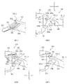
도 4a는 한 실시 예에 따른 제1 스트랩 체결부를 포함하는 제1 스트랩의 제1 방향 관측 상태를 나타낸 도면이다.
도 4b는 한 실시 예에 따른 제1 스트랩 체결부를 포함하는 제1 스트랩 중 제2 거치부가 제거된 구조의 한 예를 나타낸 도면이다.
도 4c는 한 실시 예에 따른 제1 스트랩 체결부를 포함하는 제1 스트랩의 제2 거치부 구조의 한 예를 나타낸 도면이다.
도 4d는 한 실시 예에 따른 제1 거치부 및 제2 거치부를 포함하는 제1 스트랩 체결부 구조의 제2 방향 관측 도면이다.
도 5a는 제2 실시 예에 따른 스트랩의 일부 구조의 제1 방향 및 제2 방향 관측 상태를 나타낸 도면이다.
도 5b는 제2 실시 예에 따른 스트랩의 제2 거치부 구조의 한 예를 나타낸 도면이다.
도 6은 제2 실시 예에 따른, 스트랩 구조의 제2 거치부 결합 형태를 설명하는 도면이다.
도 7은 제2 실시 예에 따른 스트랩과 하우징 결합 구조의 한 예를 나타낸 도면이다.
도 8은, 제2 실시 예에 따른 스트랩과 하우징 결합 구조의 일 단면을 나타낸 도면이다.
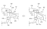
도 9는 제3 실시 예에 따른 스트랩 구조의 한 예를 나타낸 도면이다.
도 10은 제3 실시 예에 따른 스트랩 체결의 한 예를 나타낸 도면이다.1 is a diagram illustrating an example of an exploded perspective view of a wearable electronic device according to an embodiment of the present invention.
2 is a diagram illustrating an example of a configuration of a housing among configurations of a wearable electronic device according to various embodiments of the present disclosure;
3 is a diagram illustrating an example of a structure of a first strap and a connection relationship with a housing among components of a wearable electronic device according to various embodiments of the present disclosure;
4A is a view illustrating a first direction observation state of a first strap including a first strap fastening part according to an exemplary embodiment.
4B is a diagram illustrating an example of a structure in which a second mounting part is removed among a first strap including a first strap fastening part according to an embodiment.
4C is a view illustrating an example of a structure of a second mounting part of a first strap including a first strap fastening part according to an embodiment.
4D is a second direction observation view of a structure of a first strap fastening part including a first mounting part and a second mounting part according to an exemplary embodiment.
5A is a view illustrating a first direction and a second direction observation state of a partial structure of a strap according to the second embodiment.
5B is a view showing an example of a structure of a second mounting part of a strap according to the second embodiment.
6 is a view for explaining the coupling form of the second mounting portion of the strap structure according to the second embodiment.
7 is a view showing an example of a structure in which a strap and a housing are coupled according to a second embodiment.
8 is a view showing a cross-section of a structure combining a strap and a housing according to a second embodiment.
9 is a view showing an example of a strap structure according to the third embodiment.
10 is a view showing an example of strap fastening according to the third embodiment.
이하, 본 발명의 다양한 실시 예가 첨부된 도면을 참조하여 기재된다. 그러나, 이는 본 발명을 특정한 실시 형태에 대해 한정하려는 것이 아니며, 본 발명의 실시 예의 다양한 변경(modification), 균등물(equivalent), 및/또는 대체물(alternative)을 포함하는 것으로 이해되어야 한다. 도면의 설명과 관련하여, 유사한 구성요소에 대해서는 유사한 참조 부호가 사용될 수 있다.Hereinafter, various embodiments of the present invention will be described with reference to the accompanying drawings. However, this is not intended to limit the present invention to specific embodiments, and it should be understood that various modifications, equivalents, and/or alternatives of the embodiments of the present invention are included. In connection with the description of the drawings, like reference numerals may be used for like components.
도 1은 본 발명의 실시 예에 따른 웨어러블 전자 장치의 분해 사시도의 한 예를 나타낸 도면이다.1 is a diagram illustrating an example of an exploded perspective view of a wearable electronic device according to an embodiment of the present invention.
도 1을 참조하면, 본 발명의 실시 예에 따른 웨어러블 전자 장치(100)는 본체부(110, 120, 140, 150, 160) 및 스트랩(131, 132)를 포함할 수 있다. Referring to FIG. 1 , a wearable
상기 본체부(110, 120, 140, 150, 160)는 예컨대, 디스플레이(110), 하우징(120), 전자 요소(140), 후면 커버(150) 및 후면 레이어(160)를 포함할 수 있다. 상기 전자 요소(140)는 상기 하우징(120) 내측에 배치되며 상기 디스플레이(110) 구동과 관련한 프로세서와 메모리 등이 실장된 인쇄회로기판, 상기 인쇄회로기판에 전원을 공급하는 배터리, 오디오 신호를 출력하는 스피커, 오디오 신호를 수집하는 마이크, 사용자 입력에 따른 입력 신호를 생성하는 적어도 하나의 물리 버튼(예: 측면 버튼), 적어도 하나의 센서를 포함할 수 있다. 상술한 인쇄회로기판이나 배터리와 같은 전자 요소(140)는 상기 하우징(120) 내측에 안착되고, 디스플레이(110)에 의해 가려지는 경우, 외부에서 관측되지 않을 수 있다. 상기 센서는 예컨대 상기 하우징(120) 일측을 통하여 적어도 일부가 노출될 수 있다. 이와 관련하여, 상기 센서가 노출될 수 있도록 상기 센서가 배치된 상기 하우징(120)의 외측 주변부에 센서 홀이 형성될 수 있다. The
상기 디스플레이(110)는 적어도 일부가 상기 하우징(110)에 마련된 개구 영역을 통하여 노출되고, 프로세서 제어에 대응하여 또는 디스플레이 구동 회로의 제어에 대응하여 지정된 기능 화면을 출력할 수 있다. 상기 디스플레이(110)는 예컨대, 외부 보호 부재(예: 전면 커버, 윈도우 또는 윈도우 글래스), 디스플레이 패널, 터치 패널 등을 포함할 수 있다. 또한, 상기 디스플레이(110)는 디스플레이 패널의 방열 및 보호를 수행하는 방열판이나 엠보층 등을 더 포함할 수 있다. 추가적으로, 상기 웨어러블 전자 장치(100)는 상기 디스플레이(110) 구동과 관련한 디스플레이 구동 회로(예: DDI, display driver IC)를 더 포함할 수 있다. 상기 디스플레이 구동 회로는 화면이 출력되는 적어도 하나의 픽셀로 구성된 디스플레이 패널과 FPCB(Flexible Printed Circuit Board)로 연결될 수 있다. 상기 디스플레이(110)(또는 디스플레이 장치)는 예컨대, 테두리가 원형으로 마련될 수 있다. 상기 디스플레이(110)는 상기 하우징(120) 일측에 안착되어, 상기 테두리는 상기 하우징(120)의 내측면에 의해 감싸질 수 있다. At least a part of the
상기 하우징(120)은 예컨대, 중심부가 상하로 관통되는 홀을 포함하는 링 형상으로 마련될 수 있다. 상기 하우징(120)은 적어도 일부가 금속 재질로 마련될 수 있다. 다양한 실시 예에 따르면, 상기 하우징(120)의 적어도 일부는 비금속 재질로 마련되고, 상기 비금속 재질로 형성된 영역에 의해 분리된 일부 금속 재질 영역은 안테나로 이용될 수 있다. 상기 하우징(120)의 상단부에는 상기 디스플레이(110)의 적어도 일부가 외부로 노출되도록 배치될 수 있다. 이와 관련하여, 상기 하우징(120)의 상단부 일측에는 디스플레이(110)가 안착 및 고정될 수 있는 안착부가 단차지게 형성되고, 상기 디스플레이(110)와 상기 안착부 사이에는 접착 부재가 배치될 수 있다. 상기 하우징(120)의 내측면은 중심부가 빈 원통의 내벽 형상으로 마련될 수 있다. 상기 하우징(120)의 외측면은 적어도 일부가 볼록하게 형성될 수 있다. 한 실시 예에 따르면, 상기 하우징(120)의 외측면은 중심부가 상단 및 하단보다 볼록하게 형성될 수 있다. 상기 하우징(120)의 외측면에는 스트랩(131, 132)이 연결될 수 있는 스트랩 연결 구조가 형성될 수 있다.The
상기 전자 요소(140)는 예컨대, 인쇄회로기판, 인쇄회로기판과 상기 디스플레이(110)에 전원을 공급하는 배터리를 포함하고, 웨어러블 전자 장치(100)의 기능 지원과 관련한 다양한 입출력 모듈 및 센서 중 적어도 하나를 포함할 수 있다. 상기 전자 요소(140)는 하우징(120) 내측에 안착 및 배치될 수 있다. 이와 관련하여, 상기 전자 요소(140)의 적어도 일부의 외형은 원형의 띠 또는 동전 형태로 마련될 수 있다. 상기 전자 요소(140)의 상부에는 디스플레이(110)가 배치되고, 상기 전자 요소(140)의 하부에는 후면 커버(150)가 배치될 수 있다. The
상기 후면 커버(150)는 상기 하우징(120)의 후면 방향(예: 디스플레이(110)가 배치된 방향을 하우징(120)의 전면 방향으로 할 경우, 상기 디스플레이(110)가 배치된 방향의 반대 방향)에서 전면 방향으로 하우징(120)에 체결될 수 있다. 상기 후면 커버(150)는 하우징(120)의 내측에 배치된 전자 요소(140)의 하우징(120) 내에서의 움직임 또는 유동을 방지할 수 있다. 또한, 상기 후면 커버(150)는 하우징(120) 내측에 배치된 전자 요소(140)가 이탈하는 것을 방지할 수 있다. 상기 후면 커버(150)는 하우징(120)의 후면 방향에 형성된 안착부에 안착될 수 있다. 상기 후면 커버(150) 고정과 관련하여, 상기 후면 커버(150)와 상기 하우징(120)의 사이의 적어도 일부 영역(예: 상기 후면 커버(150)의 가장자리 영역 및 상기 하우징(120)의 내측 가장자리 영역 사이에는 접착 부재 또는 체결 부재(예: 스크류)가 배치될 수 있다. 이와 관련하여, 상기 후면 커버(150)는 원형의 띠 형상으로 마련되고, 상기 하우징(120)과 결합할 수 있는 적어도 하나의 돌기 또는 보스가 배치될 수 있다. The
상기 후면 레이어(160)는 상기 후면 커버(150)의 후면(예: 디스플레이(110)가 배치된 방향을 전면 방향으로 할 경우, 반대 방향의 면)에 접착 또는 고정될 수 있다. 상기 후면 레이어(160)의 적어도 일부는 비금속 재질로 형성될 수 있다. 상기 후면 레이어(160)는 예컨대, 무선 충전과 관련한 코일의 적어도 일부가 배치될 수 있다. 한 실시 예에 따르면, 상기 코일은 상기 후면 커버(150)와 마주보는 상기 후면 레이어(160)의 전면 방향에 배치될 수 있다. 상기 후면 레이어(160)와 상기 후면 커버(150) 사이에 접착 부재가 배치되어, 후면 레이어(160)는 상기 후면 커버(150)의 후면에 접착될 수 있다. The
상기 스트랩(131, 132)은 상기 하우징(120) 일측 및 타측에 각각 체결될 수 있다. 예컨대, 스트랩(131, 132)은 하우징(120) 일측에 연결되는 제1 스트랩(131)(또는 제1 스트랩 구조)과, 하우징(120) 타측에 연결되는 제2 스트랩(132)(또는 제2 스트랩 구조)을 포함할 수 있다. 상기 제1 스트랩(131)은 예컨대, 스트랩 숏 바디(131_1), 바디 홀(131_3a), 버클(131_3b), 고리(131_3c), 하우징(120)과 체결되는 제1 스트랩 체결부(139a) 및 상기 제1 스트랩 체결부(139a)가 안착되는 제1 스트랩 고정부(131_2)를 포함할 수 있다. 상기 제1 스트랩 고정부(131_2)의 적어도 일부는 상기 스트랩 숏 바디(131_1)의 일부에 포함될 수 있다. The
상기 스트랩 숏 바디(131_1)는 가죽이나, 고무, 금속 부재와 같은 다양한 재질 중 적어도 하나의 재질로 마련될 수 있다. 상기 스트랩 숏 바디(131_1)는 하우징(120)에서 멀어지는 방향으로 일정 길이와 폭을 가지며 형성되고, 적어도 일부가 납작한 형상을 포함할 수 있다. 상기 스트랩 숏 바디(131_1)에 연결된 버클(131_3b)은 제2 스트랩(132)이 연결될 수 있는 바디 홀(131_3a)을 포함할 수 있다. 상기 바디 홀(131_3a)은 예컨대, 상기 제2 스트랩(132)의 폭보다 큰 폭을 가지며 형성될 수 있다. 상기 버클(131_3b)에는 고리(131_3c)가 배치되고, 상기 고리(131_3c)는 상기 제2 스트랩(132)에 형성된 고리 홀들(132_3)에 삽입 및 체결될 수 있다. 상기 제1 스트랩 고정부(131_2)는 상기 스트랩 숏 바디(131_1) 일측에 형성되며, 제1 스트랩 체결부(139a)가 고정될 수 있다. 상기 제1 스트랩 체결부(139a)는 하우징(120)에 형성된 스트랩 연결 구조에 적어도 일부가 체결될 수 있다. 상기 제1 스트랩 체결부(139a)는 상기 제1 스트랩 고정부(131_2)와 동일 또는 다른 재질로 형성될 수 있다.The strap short body 131_1 may be made of at least one of various materials such as leather, rubber, and a metal member. The strap short body 131_1 is formed to have a predetermined length and width in a direction away from the
상기 제2 스트랩(132)은 예컨대, 스트랩 롱 바디(132_1), 고리 홀들(132_3), 제2 스트랩 고정부(132_2) 및 제2 스트랩 체결부(139b)를 포함할 수 있다. 상기 제2 스트랩 고정부(132_2)의 적어도 일부는 상기 스트랩 롱 바디(132_1)의 일부에 포함될 수 있다. 상기 스트랩 롱 바디(132_1)는 예컨대, 상기 스트랩 숏 바디(131_1)에 비해서 상대적으로 더 긴 길이를 가지며 형성될 수 있다. 상기 스트랩 롱 바디(132_1)는 상기 스트랩 숏 바디(131_1)와 동일한 두께 및 폭을 가지며 형성될 수 있다. 상기 고리 홀들(132_3) 중 적어도 하나는, 상기 제2 스트랩(132)이 제1 스트랩(131)과 체결되는 과정에서, 고리(131_3c)가 삽입되는데 이용될 수 있다. 상기 제2 스트랩 고정부(132_2)는 앞서 설명한 제1 스트랩 고정부(131_2)와 동일한 구조 및 재질로 형성될 수 있다. 상기 제2 스트랩 체결부(139b)는 상기 제1 스트랩 체결부(139a)와 동일한 구조 및 재질로 형성될 수 있다. 또는, 다양한 실시 예에 따르면, 이하에서 설명하는, 스트랩 체결부의 다양한 실시 예들 중 적어도 하나가, 제1 스트랩 체결부(139a) 및 제2 스트랩 체결부(139b)에 동일하게 또는 서로 다른 구조의 실시 예가 적용될 수 있다.The
도 2는 다양한 실시 예에 따른 웨어러블 전자 장치 구성 중 하우징의 구성의 한 예를 나타낸 도면이다. 도 2에서, 201 상태는 하우징의 외관에 대응하는 사시도의 한 예이며, 203 상태는 201 상태에서의 A-A` 절단선을 따른 단면의 일부 예를 나타낸 도면이다.2 is a diagram illustrating an example of a configuration of a housing among configurations of a wearable electronic device according to various embodiments of the present disclosure; In FIG. 2 , a
도 1 및 도 2를 참조하면, 상기 하우징(120)은 하우징 바디(122), 상기 하우징 바디(122) 일측에 형성된 적어도 하나의 키 버튼(129), 스트랩(131, 132)이 체결되는 스트랩 연결 구조(120a)를 포함할 수 있다. 여기서, 상기 스트랩 연결 구조(120a)는 하우징(120)에 연결되는 스트랩의 개수에 따라 달라질 수 있다. 예컨대, 도 1에서와 같이, 2개의 스트랩(131, 132)기 하우징(120)과 체결되는 경우, 하우징(120)에는 2개의 스트랩 연결 구조(120a)가 배치될 수 있다. 1 and 2 , the
상기 하우징 바디(122)는 중심부가 상하로 관통되는 링 형상으로 마련되며, 내측은 평평한 곡면을 형성(예: z축 방향으로 평평하고, xy 평면으로 원형을 형성)하고, 외측은 z축 방향으로 굴곡진 상태이며, 하우징의 중심에서 외측 방향으로 볼록한 형상으로 마련될 수 있다. 상기 하우징 바디(122)의 외측 적어도 일부에 상기 스트랩 연결 구조(120a)가 배치될 수 있다. 2개의 스트랩 연결 구조(120a)가 하우징 바디(122)에 형성되는 경우, 2개의 스트랩 연결 구조(120a)는 하우징 바디(122)의 중심점을 기준으로 대칭되도록 형성될 수 있다. 상기 적어도 하나의 키 버튼(129)이 배치되는 영역의 하우징 바디(122)에는 측면을 관통하는 홀이 형성되고, 해당 홀의 적어도 일부에 상기 적어도 하나의 키 버튼(129)이 안착될 수 있다. The
상기 하우징 바디(122)의 상측(예: z축)에는 제1 안착부(121a)와 전면 베젤(123a)이 배치될 수 있다. 상기 제1 안착부(121a)는 상기 하우징 바디(122)의 z축 방향 상단에서, 평평하게 형성될 수 있다. 한 실시 예에 따르면, 상기 제1 안착부(121a)의 적어도 일부와 상기 하우징 바디(122)의 적어도 일부는 서로 수직하게 배치될 수 있다. 상기 제1 안착부(121a)는 띠 형상으로 마련되며, 상기 디스플레이(110)의 외곽 적어도 일부가 안착될 수 있다. 상기 제1 안착부(121a)와 상기 디스플레이(110) 사이 적어도 일부에는 접착 부재가 배치될 수 있다. 상기 전면 베젤(123a)은 상기 제1 안착부(121a)의 외곽 적어도 일부를 감싸도록 배치될 수 있다. 상기 전면 베젤(123a)은 띠 형상의 상기 제1 안착부(121a)를 따라 띠 형상으로 마련될 수 있다. 한 실시 예에 따르면, 상기 전면 베젤(123a)은 상기 제1 안착부(121a)의 일측 가장자리(예: x축 가장자리)에서 상기 제1 안착부(121a)와 일정 각도(예: 수직 각도)를 형성하면 상측(예: z축)으로 일정 높이만큼 연장되어 형성될 수 있다. 상기 전면 베젤(123a)의 외측은 상측에서 하측으로 갈수록 점진적으로 두께가 줄어든 형상을 가질 수 있다. A
상기 하우징 바디(122)의 하측(예: -z축)에는 제2 안착부(121b)와 후면 베젤(123b)이 배치될 수 있다. 상기 제2 안착부(121b)는 상기 하우징 바디(122)의 -z축 방향 하단에서, 평평하게 형성될 수 있다. 한 실시 예에 따르면, 상기 제2 안착부(121b)의 적어도 일부와 상기 하우징 바디(122)의 적어도 일부는 서로 수직하게 배치될 수 있다. 상기 제2 안착부(121b)는 띠 형상으로 마련되며, 상기 후면 커버(150)의 외곽 적어도 일부가 안착될 수 있다. 상기 제2 안착부(121b)와 상기 후면 커버(150) 사이 적어도 일부에는 접착 부재가 배치될 수 있다. 상기 제2 안착부(121b)는 상기 하우징 바디(122)의 중심점에서의 xy 평면을 기준으로, 상기 제1 안착부(121a)와 z축 방향으로 대칭되게 형성될 수 있다. 상기 후면 베젤(123b)은 상기 제2 안착부(121b)의 외곽 적어도 일부를 감싸도록 배치될 수 있다. 상기 후면 베젤(123b)은 상기 전면 베젤(123a)과 유사하게 띠 형상의 상기 제2 안착부(121b)를 따라 띠 형상으로 마련될 수 있다. 상기 후면 베젤(123b)은 상기 하우징 바디(122)의 중심점에서의 xy 평면을 기준으로, 상기 전면 베젤(123a)과 z축 방향으로 대칭되게 형성될 수 있다.A
상기 스트랩 연결 구조(120a)는 상기 하우징 바디(122)의 외곽 일측에 적어도 하나가 형성될 수 있다. 한 실시 예에 따르면, 상기 스트랩 연결 구조(120a)의 적어도 일부는 상기 하우징 바디(122)의 외곽에서 내측으로 일정 깊이만큼 파여진 홈 형상을 포함할 수 있다. 다양한 실시 예에 따르면, 상기 스트랩 연결 구조(120a)는 하우징 바디(122)의 외곽에 형성된 일정 깊이는 개구(125)(예: recess part)와, 상기 하우징 바디(122)의 중심점에서 xy 평면을 기준으로 상기 개구(125)에 연장되고 z축 방향 및 -z축 방향으로 0도 보다 크거나 작은 기울기를 가지며 상기 하우징 바디(122)의 내측 방향으로 형성된 제1 거치 홈(127a) 및 제2 거치 홈(127b)을 포함할 수 있다. At least one
다양한 실시 예에 따르면, 수평 방향을 기준으로, 상기 개구(125)에서 상기 하우징 바디(122)의 내측 방향과 상기 하우징 바디(122)의 중심에서 z축 방향에 해당하는 수직 방향(예: 수직 방향 중 상측 수직 방향, z축 방향) 사이 제1 대각선 방향에 제1 거치 홈(127a)이 배치될 수 있다. 상기 수평 방향을 기준으로, 상기 개구(125)에서 상기 하우징 바디(122)의 내측 방향과 수직 방향(예: 수직 방향 중 하측 수직 방향, -z축 방향)) 사이 제2 대각선 방향에 제2 거치 홈(127b)이 배치될 수 있다. 상기 제1 대각선 방향과 상기 제2 대각선 방향은 상기 수평 방향 기준으로 상하(또는 수직 방향)로 대칭되게 배치될 수 있다. According to various embodiments, a vertical direction (eg, a vertical direction) corresponding to the inner direction of the
상기 제1 거치 홈(127a)은 예컨대, 하우징 바디(122)의 중심점에서 내측 방향으로 z축 방향 기준 90도보다 큰 기울기(예: 180~90도 사이의 각도)를 가지는 제1 경사면(126a)과, 상기 개구(125)(예: recess)를 형성하며 상기 제1 경사면(126a)과 일정 간격 이격되고 상기 전면 베젤(123a)과 반대 방향으로 돌출된 제1 거치 행오버(124a)를 포함할 수 있다. 상기 제1 경사면(126a)과 상기 제1 거치 행오버(124a) 사이의 최단 이격 거리는 삽입되는 스트랩의 거치부 두께에 대응될 수 있다. 상기 제1 경사면(126a)은 상기 제1 거치 행오버(124a)보다 하우징 바디(122)의 중심에 더 가깝게 배치될 수 있다. 상기 제1 거치 행오버(124a)의 길이는 상기 제1 경사면(126a)의 길이보다 짧게 형성될 수 있다. 상기 제1 경사면(126a)과 제1 거치 행오버(124a)의 단면 모양은 전체적으로 갈고리 형상으로 마련될 수 있다. 상기 개구(125)는 관측 방향에 따라, recess(홈) 또는 홀(opening)로 구분될 수 있다. 예컨대, 하우징 바디(122)의 측면에서 볼 때, 개구(125)는 홈으로 구분할 수 있으며, 거치 행오버(124a, 124b)의 측면에서 홀로 구분될 수 있다. The
상기 제2 거치 홈(127b)은 예컨대, 하우징 바디(122)의 중심점에서 내측 방향으로 -z축 방향 기준 -90도 보다 작은(예: 180~-90 사이의 각도) 기울기를 가지는 제2 경사면(126b)과, 상기 개구(125)를 형성하며 상기 제2 경사면(126b)과 일정 간격 이격되고 상기 후면 베젤(123b)과 반대 방향으로 돌출된 제2 거치 행오버(124b)를 포함할 수 있다. 상기 제2 경사면(126b)과 상기 제2 거치 행오버(124b)의 최단 이격 거리는 삽입되는 스트랩의 거치부 두께에 대응될 수 있다. 상기 제2 거치 홈(127b)은 예컨대, 하우징 바디(122)의 중심점을 기준으로 상하로 대칭되게 형성될 수 있다. 상기 제2 경사면(126b)은 상기 하우징 바디(122)의 중심점을 기준으로 상하로 대칭되게 형성될 수 있다. 상기 제2 경사면(126b)은 제2 거치 행오버(124b)보다 하우징 바디(122)의 중심에 더 가깝게 배치될 수 있다. 상기 제2 거치 행오버(124b)의 길이는 상기 제2 경사면(126b)의 길이보다 짧게 형성될 수 있다. 다양한 실시 예에 따르면, 상기 제2 거치 행오버(124b)의 돌출된 길이는 제1 거치 행오버(124a)의 돌출된 길이와 동일한 길이를 가질 수 있다. 상기 제2 경사면(126b)과 제2 거치 행오버(124b)의 단면 모양은 상기 제1 경사면(126a) 및 제1 거치 행오버(124a)의 단면 모양과 동일 또는 유사한 모양을 가질 수 있다.The
다양한 실시 예에 따르면, 상기 제1 경사면(126a) 및 제2 경사면(126b)은 상기 스트랩 연결 구조(120a)의 일부 영역에 형성될 수 있다. 예를 들어, 상기 스트랩 연결 구조(120a)는 상기 하우징 바디(122)의 외측면에 형성되며 z축 방향 또는 -z축 방향의 홈의 높이보다, xy 평면 방향의 홈의 길이가 더 길게 형성될 수 있다. 상기 제1 경사면(126a)의 밑단(예: -z축 방향의 가장자리)과 상기 제2 경사면(126b)의 윗단(예: z축 방향의 가장자리)은 서로 연결될 수 있다. According to various embodiments, the first
상기 스트랩 연결 구조(120a)의 중심부는 앞서 설명한 개구(125)와, 제1 경사면(126a) 및 제2 경사면(126b)이 형성되고, 상기 스트랩 연결 구조(120a)의 중심부 기준 양측에는 일정 깊이를 가지는 홈이 단차진 형태로 마련될 수 있다. 상기 단차진 홈은 예컨대, 스트랩(131, 132)에 형성된 날개부들이 접촉되는 스트랩 접촉 영역(120a_1, 120a_2)을 형성할 수 있다. The above-described
상기 스트랩 연결 구조(120a)의 중심부(예: 제1 경사면(126a)과 제2 경사면(126b)이 형성된 영역 또는 제1 거치 홈(127a) 및 제2 거치 홈(127b)이 형성된 영역)에는 스트랩(131, 132)의 중심부(예: 후술하는 제1 거치부와 제2 거치부)가 체결되고, 상기 스트랩 연결 구조(120a)의 양측에는 상기 스트랩(131, 132)의 양측 날개부가 접촉되도록 체결될 수 있다. 이와 관련하여, 상기 스트랩 연결 구조(120a)는 제1 스트랩(131)의 제1 거치부(310) 및 제2 거치부(200)가 체결되는 부분의 양 옆으로 일정 깊이를 가지는 제1 날개 안착부(120a_1) 및 제2 날개 안착부(120a_2)가 형성될 수 있다. 다양한 실시 예에 따르면, 상기 제1 거치 홈(127a) 및 제2 거치 홈(127b)에는 후크와 같은 돌출 구조 또는 함몰 구조가 형성되어, 스트랩과의 체결력을 높일 수 있다. 돌출 구조는 예컨대, 제1 거치 행오버(124a)의 내측(예: -x축과 -z축 사이의 가장자리)에서 하우징(120)의 내측 방향(예: -x축과 -z축 사이의 방향)으로 돌출되는 구조를 포함할 수 있다. 함몰 구조는 예컨대, 제1 거치 행오버(124a)의 내측면(예: -x축과 -z축 사이의 가장자리)에서 하우징(120)의 외측 방향(예: x축과 z축 사이의 일 방향)으로 함몰된 리세스를 포함할 수 있다. 상기 돌출 구조 또는 함몰 구조는 제2 거치 행오버(124b)에도 동일하게 형성될 수 있다. 상기 제1 거치 홈(127a) 및 제2 거치 홈(127b)에 상술한 돌출 구조 또는 함몰 구조가 형성되는 경우, 하우징(120)에 삽입된 스트랩의 형상(예: 스트랩 체결부(139a, 139b)에 배치된 거치부(310, 200)의 형상)이 돌출 구조 또는 함몰 구조에 대응되는 모양을 가질 수 있다. 예컨대, 거치부(310, 200)의 일정 부분의 형상(예: 거치 홈(127a, 127b)에 삽입되는 부분)은 돌출 구조의 일측과 체결되는 후크 형태 또는 함몰 구조에 삽입되는 고리 형태로 마련될 수 있다. In the central portion of the
도 3은 다양한 실시 예에 따른 웨어러블 전자 장치 구성 중 제1 스트랩의 구조 및 하우징과의 연결 관계의 한 예를 나타낸 도면이다. 3 is a diagram illustrating an example of a structure of a first strap and a connection relationship with a housing among components of a wearable electronic device according to various embodiments of the present disclosure;
301 상태는, 제1 스트랩(131) 중 제1 스트랩 체결부(139a) 내측이 관측되는 방향을 나타낸 것이며, 303 상태는, 제1 스트랩(131)의 제1 거치부(310)가 제1 거치 홈(127a)에 진입하는 상태를 나타낸 것이다. 305 상태는, 제1 스트랩(131)의 제1 거치부(310)가 제1 거치 홈(127a)에 삽입된 상태에서, 제2 거치부(200)가 눌려져 xz축 방향으로 일정 거리만큼 이동된 상태(또는 최대로 이동된 상태)를 나타낸 것이고, 307 상태는, 제1 스트랩(131)의 제1 거치부(310)가 제1 거치 홈(127a)에 삽입되고, 제2 거치부(200)가 제2 거치 홈(127b)에 삽입된 상태를 나타낸 것이다.
도 1 내지 도 3을 참조하면, 301 상태에서와 같이, 제1 스트랩(131)은 제1 스트랩 숏 바디(131_1)의 일측(예: -x축 방향의 가장자리)에 제1 스트랩 고정부(131_2)가 배치되고, 상기 제1 스트랩 고정부(131_2)에는 거치 바디(320)가 고정될 수 있다. 상기 제1 스트랩 고정부(131_2)는 제1 스트랩 숏 바디(131_1)의 -x축 방향 가장자리를 형성하는 밑단 부분과, 제1 스트랩 숏 바디(131_1)의 상단에서-x축 방향으로 연장되며 제1 스트랩 숏 바디(131_1)보다 얇은 두께를 형성한 연장부분을 포함할 수 있다. 상기 거치 바디(320)는 상기 제1 스트랩 고정부(131_2)와 동일 또는 유사한 구조를 가질 수 있다. 예컨대, 거치 바디(320)는 제1 스트랩 고정부(131_2)의 밑단 부분에 고정되며 제2 거치부(200)를 지지하는 하단부와, 제1 스트랩 고정부(131_2)의 연장 부분 아래에 배치되며, -x축 방향으로 연장되어 적어도 일부가 제1 거치부(310)를 형성하는 상단 부분을 포함할 수 있다. 상기 제1 거치부(310)는 상기 거치 바디(320)의 상단 부분 중 -x축 방향으로 연장된 기본 베이스(310a)와, 상기 기본 베이스(310a)의 가장자리에서 z축과 -x축 사이의 대각선 방향으로 연장된 거치 영역(310b)을 포함할 수 있다. 상기 제1 거치 홈(127a)의 크기는 상기 제1 거치부(310)의 끝단(예: 거치 영역(310b))의 두께보다 크게 형성될 수 잇다. 상기 거치 바디(320)의 상측(예: z축 방향) 적어도 일부에는 제1 거치부(310)가 형성되고, 하측(예: -z축 방향) 또는 측면(예: -x축 방향) 적어도 일부에는 제2 거치부(200)가 배치될 수 있다. 1 to 3 , as in the 301 state, the
303 상태에서와 같이, 웨어러블 전자 장치(100)는 하우징(120) 상측에 디스플레이(110)가 안착되고, 하우징(120)의 하측에 후면 커버(150)가 결합될 수 있다. 상기 하우징(120) 내측 적어도 일부는 상하로 관통되는 빈 공간을 형성하고, 상기 하우징(120) 내측의 빈 공간에는 앞서 언급한 전자 요소(140)의 적어도 일부가 배치될 수 있다. 상기 제1 거치부(310)는 거치 바디(320)로부터 연장되는 기본 베이스(310a)와, 상기 기본 베이스(310a)로부터 연장되며 제1 거치 홈(127a)에 적어도 일부가 삽입되는 거치 영역(310b)을 포함할 수 있다. 전체적인 제1 거치부(310) 형상은 좌우가 뒤집힌 L자 형태로 형성될 수 있다. 제2 거치부(200)는 별도 구조물로 형성되어 거치 바디(320) 일측에 체결될 수 있다. 예컨대, 제2 거치부(200)는 거치 바디(320)의 측면에 체결된 후, 외부에서 가해지는 상하 방향(예; -z축 ~ z축 방향) 압력에 따라 상하 방향으로 이동될 수 있다. 상기 제1 거치부(310)는 제1 스트랩 숏 바디(131_1)를 수평하게 배치한 상태에서, z축과 -x축 사이의 대각선 방향으로 배치될 수 있다. 제2 거치부(200)는 제1 스트랩 숏 바디(131_1)를 수평하게 배치한 상태에서, -z축 방향으로 향하는 거치 레일(또는 거치 돌기)를 포함할 수 있다. 제1 스트랩(131)을 스트랩 연결 구조(120a)에 체결하는 과정에서 제1 스트랩 숏 바디(131_1)를 하우징(120)의 일측에 수평하게 놓은 뒤 스트랩 연결 구조(120a)의 개구(125)를 통해 제1 거치부(310)를 진입시키면서, 제1 거치 홈(127a)에 삽입할 수 있다. 이 과정에서, 제2 거치부(200)를 가압하여, 상측(예: z축 방향)으로 이동시킬 수 있다. As in
다양한 실시 예에 따르면, 상기 개구(125)의 크기는 상기 제1 거치부(310)의 상측 끝단(예: 거치 영역(310b)의 끝단)과 상기 제2 거치부(200)의 하측 끝단 사이의 이격 거리보다 작게 형성될 수 있다. 다양한 실시 예에 따르면, 가압에 의하여 상기 제2 거치부(200)가 거치 바디(320)의 내측으로 이동된 상태에서, 상기 개구(125)의 크기는 상기 제1 거치부(310)의 상측 끝단(예: 거치 영역(310b)의 끝단)과 이동된 제2 거치부(200)(예: z축 방향으로 이동될 수 있는 최대 거리로 이동된 상태의 제2 거치부(200))의 하측 끝단 사이의 이격 거리보다 크게 형성될 수 있다.According to various embodiments, the size of the
305 상태에서와 같이, 제1 스트랩 숏 바디(131_1)를 우하측(예: -z축 ~ x축 사이의 대각선)으로 기울이면, 제1 거치 홈(127a)에 제1 거치부(310)가 삽입되고, 이 과정에서, 제2 거치부(200)의 거치 레일(또는 거치 돌기) 제2 경사면(126b) 일측과 접촉되거나 제2 경사면(126b)가 나란하게 배치될 수 있다. 이 과정에서, 제2 거치부(200)의 가압 상태를 유지하여, 제1 거치부(310)와 제2 거치부(200) 사이의 이격 거리를 좁힌 상태에서 스트랩 연결 구조(120a)에 제1 스트랩 체결부(139a)를 삽입할 수 있다. As in
제2 거치부(200)가 제2 경사면(126b)에 나란하게 배치된 상태에서, 제2 거치부(200)에 가해진 압력이 제거되면, 307 상태에서와 같이, 제1 거치부(310)는 제1 거치 홈(127a)에 삽입되고, 제2 거치 홈(127b)은 제2 거치 홈(127b)에 삽입될 수 있다. 스트랩 숏 바디(131_1)가 하우징(120)에 체결되면, 상기 스트랩 숏 바디(131_1)는 x축 및 -z축 사이의 일정 대각선 방향으로 거치되고, 이에 대응하여, 제1 거치부(310)는 제1 경사면(126a)에 대응하는 방향으로 배치되고, 제2 거치부(200)는 제2 경사면(126b)에 대응하는 방향으로 배치될 수 있다. 한 실시 예에 따르면, 하우징(120)의 중심점을 기준으로 제1 거치부(310)는 좌상측(z축 ~ -x축 사이) 대각선 방향으로 배치되고, 제2 거치부(200)는 좌하측(-z축 ~ -x축 사이) 대각선 방향으로 배치되고, x축 또는 -x축 기준으로 상하로 대칭되게 배치될 수 있다. 제2 거치부(200)에 가해진 압력이 제거되면서, 제1 거치부(310)와 제2 거치부(200) 사이의 간격은 301 상태에 비하여 상대적으로 더 크게 형성될 수 있다. 제1 스트랩(131)이 스트랩 연결 구조(120a)에 안착되는 동안, 제1 스트랩(131)에 배치된 제1 날개부(311) 및 제2 날개부(312)는 스트랩 연결 구조(120a)에 형성된 날개 안착부들(120a_1, 120a_2)에 안착될 수 있다. When the pressure applied to the second mounting
도 4a는 한 실시 예에 따른 제1 스트랩 체결부를 포함하는 제1 스트랩의 제1 방향 관측 상태를 나타낸 도면이고, 도 4b는 한 실시 예에 따른 제1 스트랩 체결부를 포함하는 제1 스트랩 중 제2 거치부가 제거된 구조의 한 예를 나타낸 도면이다. 도 4c는 한 실시 예에 따른 제1 스트랩 체결부를 포함하는 제1 스트랩의 제2 거치부 구조의 한 예를 나타낸 도면이고, 도 4d는 한 실시 예에 따른 제1 거치부 및 제2 거치부를 포함하는 제1 스트랩 체결부 구조의 제2 방향 관측 도면이다.4A is a view illustrating a first direction observation state of a first strap including a first strap fastening part according to an embodiment, and FIG. 4B is a second view of the first strap including a first strap fastening part according to an embodiment. It is a view showing an example of a structure in which the mounting portion is removed. 4C is a view showing an example of a structure of a second mounting part of a first strap including a first strap fastening part according to an embodiment, and FIG. 4D is a view showing an example of the structure of the second mounting part and the first mounting part and the second mounting part according to an embodiment It is a second direction observation view of the structure of the first strap fastening part.
도 2, 도 4a 내지 도 4d를 참조하면, 도 4a에서와 같이, 제1 스트랩(131)은 제1 스트랩 숏 바디(131_1)의 -x축 방향으로 제1 스트랩 고정부(131_2)가 배치되고, 상기 제1 스트랩 고정부(131_2)에는 거치 바디(320)가 고정될 수 있다. 한 실시 예에 따르면, 상기 제1 스트랩 고정부(131_2)는 상기 제1 스트랩 숏 바디(131_1)의 일부분으로 형성될 수 있다. 상기 제1 스트랩 고정부(131_2)와 상기 거치 바디(320)는 서로 다른 재질로 마련될 수 있다. 예컨대, 제1 스트랩 고정부(131_2)는 가죽 또는 폴리머 재질과 같이 연성을 가진 재질로 마련되고, 거치 바디(320)는 제1 스트랩 고정부(131_2)보다 강성이 큰 물질 예컨대, 플락스틱 구조물 또는 금속 구조물로 형성될 수 있다. 상기 제1 스트랩 고정부(131_2)는 거치 바디(320)가 안착되는 공간과, 제1 스트랩 체결부(139a) 중 제1 날개부(311)와 결합하는 제1 고정부(131_2a) 및 제2 날개부(312)와 결합하는 제2 고정부(131_2b)를 포함할 수 있다. 상기 제1 고정부(131_2a)는 스트랩 숏 바디(131_1)의 x축 중심에서 -y축 방향으로 연장된 날개 형상으로 마련되고, 상기 제2 고정부(131_2b)는 스트랩 숏 바디(131_1)의 x축 중심에서 y축 방향으로 연장된 날개 형상으로 마련될 수 있다. 상기 제1 고정부(131_2a)는 제1 날개부(311)와 동일 또는 유사한 형상으로 마련되고, 제1 날개부(311)와 유사한 두께를 가지며 제1 날개부(311)의 후면을 덮도록 배치될 수 있다. 상기 제2 고정부(131_2b)는 제2 날개부(312)와 동일 또는 유사한 형상으로 마련되고, 제2 날개부(312)와 유사한 두께를 가지며 제2 날개부(312)의 후면을 덮도록 배치될 수 있다. 상기 제1 고정부(131_2a)와 상기 제1 날개부(311) 사이 또는 제2 고정부(131_2b)와 제2 날개부(312) 사이에는 접착층이 배치될 수 있다. 2 and 4A to 4D, as in FIG. 4A, the
다양한 실시 예에 따르면, 제1 스트랩 고정부(131_2)의 -x축 가장자리는 제1 스트랩 체결부(139a)의 상측(예: z축 방향)의 적어도 일부를 덮도록 배치될 수 있다. 제1 거치부(310)는 z축 방향 기준으로 주변 구조물(예: 제1 날개부(311) 및 제2 날개부(312))보다 상측(z축 방향)으로 더 돌출될 수 있다. 제2 거치부(200)는 -z축 방향 기준으로 주변 구조물(예: 제1 날개부(311) 및 제2 날개부(312))보다 하측(-z축 방향)으로 더 돌출될 수 있다.According to various embodiments, the -x-axis edge of the first strap fixing part 131_2 may be disposed to cover at least a portion of an upper side (eg, z-axis direction) of the first
도 4b에서와 같이, 거치 바디(320)는 제2 거치부(200)가 안착될 수 있는 거치 공간(320a)을 제공할 수 있다. 상기 거치 공간(320a)에는 제2 거치부(200)가 안착된 후, 상기 거치 공간(320a)으로부터 이탈되지 않도록 적어도 하나의 고정 리브(320c)와 거치 단차부(320b)가 배치될 수 있다. 상기 고정 리브(320c)는 거치 공간(320a)에 제2 거치부(200)가 장착된 이후, 상기 제2 거치부(200)가 -x축 방향으로 이탈되는 것은 방지하고, 상기 거치 단차부(320b)는 거치 공간(320a)에 장착된 제2 거치부(200)가 -z축 방향으로 이탈되는 것을 방지할 수 있다. 상기 거치 바디(320)는 제2 거치부(200)를 지지하는 거치부 바닥(320d)을 포함할 수 있다. 상기 거치부 바닥(320d) 중 -x축 방향으로 연장된 부분은 상기 제1 거치부(310)를 형성할 수 있다. 상기 거치부 바닥(320d)의 크기는 제2 거치부(200) 크기에 대응될 수 있다. 다양한 실시 예에 따르면, 제1 거치부(310)의 y축(또는 -y축) 길이는 제2 거치부(200)의 y축(또는 -y축) 길이보다 길게 형성될 수 있다. As shown in FIG. 4B , the mounting
도 4c 및 도 4d에서와 같이, 제2 거치부(200)는 x축의 두께보다 y축의 길이가 더 길게 형성되며, z축 기준으로 y축과 -y축 사이에서 일정 곡률을 가지며 형성된 제1 거치 베이스(210), 상기 제1 거치 베이스(210)의 일측 가장자리(예: -x축 가장자리)에서 제1 방향(예: -z축 방향)으로 형성된 제1 거치 돌기(220), 상기 제1 거치 베이스(210)의 제2 방향(예: z축 방향)으로 형성된 제1 후크(231a)와 제2 후크(231b), 상기 제1 후크(231a)와 제2 후크(231b) 사이에 형성된 제1 탄성 고정 구조(232)와 제2 탄성 고정 구조(233)를 포함할 수 있다. 상술한 설명에서는, 2개의 탄성 고정 구조를 예시하였으나, 본 발명이 이에 한정되는 것은 아니다. 예컨대, 상기 제2 거치부(200)는 하나의 탄성 고정 구조를 가지거나 3개 이상의 탄성 고정 구조를 가질 수도 있다.4c and 4d, the second mounting
상기 제1 거치 베이스(210)는 z축 방향의 두께가 x축 방향의 두께보다 얇고, z축 방향에서 바라볼 때, 볼록한 형상을 가지며 -z축 방향에서 볼 때 오목한 형상을 가지며 y축 방향이 x축 방향보다 길게 형성된 판재 형상을 포함할 수 있다. 상기 제1 거치 돌기(220)는 상기 제2 거치 홈(127b)의 깊이와 유사하거나 또는 제2 거치 홈(127b)의 깊이와 동일한 높이를 가지며, 제1 거치 베이스(210)의 -x축 방향의 가장자리를 따라 y축(또는 -y축)으로 길게 형성될 수 있다. The
제1 후크(231a)는 제1 거치 베이스(210)의 y축 가장자리에서 z축 방향으로 돌출되어 형성되고, 후크의 돌출 방향은 제1 거치 베이스(210)의 중심점을 기준으로 일측 바깥쪽 방향(예: y축 방향)이 될 수 있다. 제1 후크(231a)는 예컨대, 거치 바디(320)에 형성된 거치 단차부(320b)에 체결될 수 있다. 제2 후크(231b)는 제1 거치 베이스(210)의 -y축 가장자리에서 z축 방향으로 돌출되어 형성되고, 제2 후크(231b)의 후크 돌출 방향은 제1 거치 베이스(210)의 중심점을 기준으로 타측 바깥쪽 방향(예: -y축 방향)이 될 수 있다. 제2 후크(231b)는 제1 후크(231a)가 체결된 거치 바디(320)의 거치 단차부(320b) 반대 방향에 형성된 거치 단차부에 결합될 수 있다. The
상기 제1 탄성 고정 구조(232)는 제1 후크(231a)에 가깝게 형성되며, 서로 마주보며 일정 간격 이격된 2개의 고정 구조들(232_1, 232_2)과, 장착된 제1 탄성 부재(235a)가 이탈되지 않도록 2개의 고정 구조들(232_1, 232_2)을 연결하는 측벽을 포함할 수 있다. 상기 2개의 이격된 고정 구조들(232_1, 232_2) 사이로 제1 탄성 부재(235a)가 삽입 및 고정될 수 있다. 상기 제1 탄성 부재(235a)는 예컨대, "V"자 형상으로 마련될 수 있다. 상기 제1 탄성 부재(235a)의 상단(예: 갈라진 부분)은 각각 제1 고정 구조(232_1) 및 제2 고정 구조(232_2)에 안착 및 고정되고, 제1 탄성 부재(235a)의 하단(예: 첨단 부분) 2개의 고정 구조들(232_1, 232_2) 사이의 공간을 통해 z축 방향으로 돌출되도록 배치될 수 있다. 이와 관련하여, 제1 탄성 부재(235a)의 z축 방향의 길이는 제1 고정 구조(232_1) 및 제2 고정 구조(232_2)의 z축 방향의 연장 길이보다 더 길게 형성될 수 있다. 상기 제1 탄성 부재(235a)는 외부에서 제2 거치부(200)에 압력이 가해지는 동안, V자의 내각이 벌어지며, z축 방향으로 돌출된 높이가 줄어들도록 변형될 수 있다. 상기 제1 탄성 부재(235a)의 "V"자 양측 가장자리가 상기 제1 고정 구조(232_1)의 측벽과 제2 고정 구조(232_2)의 측벽에 접촉될 때까지, 제2 거치부(200)가 z축 방향으로 이동될 수 있다. 상기 제2 거치부(200)에 가해진 압력이 해소되면, 제1 탄성 부재(235a)는 제1 탄성 고정 구조(232)의 상단 개구로 이전 돌출 높이를 회복하도록 배치되고, 이에 대응하여, 제2 거치부(200)는 -z축 방향으로 원복할 수 있다. 제2 탄성 부재(235b)도 상기 제1 탄성 부재(235a)와 동일 또는 유사하게 동작하면서 탄성력을 발휘할 수 있다. The first
상기 제2 탄성 고정 구조(233)는 실질적으로 제1 탄성 고정 구조(232)와 동일 또는 유사한 구조를 가질 수 있다. 한 실시 예에 따르면, 상기 제2 탄성 고정 구조(233)는 일정 간격 이격되며 일정 간격 이격된 제3 고정 구조(233_1) 및 제4 고정 구조(233_2)와, 상기 제3 고정 구조(233_1) 및 상기 제4 고정 구조(233_2)의 측면을 덮는 측벽, 제3 고정 구조(233_1)와 상기 제4 고정 구조(233_2) 사이를 통해 삽입되어, 제3 고정 구조(233_1)에 일측이 고정되고, 제4 고정 구조(233_2)에 타측이 고정되며, 상기 제3 고정 구조(233_1)와 상기 제4 고정 구조(233_2) 사이를 통해 z축 방향으로 돌출되는 제2 탄성 부재(235b)를 포함할 수 있다. 상기 제2 탄성 고정 구조(233)는 제2 후크(231b)에 가깝게 배치될 수 있다. 또는, 제2 탄성 고정 구조(233)는 제1 탄성 고정 구조(232)와 일정 간격 이격되게 배치될 수 있다. 이에 따라, 제2 탄성 고정 구조(233)는 제1 탄성 고정 구조(232)와 제2 후크(231b) 사이에 배치될 수 있다. 제2 거치부(200)의 제1 거치 베이스(210)의 탄성을 고려하여, 제1 탄성 고정 구조(232)와 제2 탄성 고정 구조(233) 사이의 이격 거리는 제1 후크(231a)와 제1 탄성 고정 구조(232) 사이의 간격 또는 제2 후크(231b)와 제2 탄성 고정 구조(233) 사이의 간격보다 크게 형성될 수 있다. 상기 제2 거치부(200)는 탄성 부재를 제외하고, 제1 거치부(310) 또는 거치 바디(320)와 동일 또는 유사한 재질로 형성될 수 있다. The second
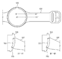
도 5a는 제2 실시 예에 따른 스트랩의 일부 구조의 제1 방향 및 제2 방향 관측 상태를 나타낸 도면이고, 도 5b는 제2 실시 예에 따른 스트랩의 제2 거치부 구조의 한 예를 나타낸 도면이다. 도 6은 제2 실시 예에 따른, 스트랩 구조의 제2 거치부 결합 형태를 설명하는 도면이다. 5A is a view showing a first direction and a second direction observation state of a partial structure of a strap according to a second embodiment, and FIG. 5B is a view showing an example of a structure of a second mounting part of the strap according to the second embodiment. to be. 6 is a view for explaining the coupling form of the second mounting portion of the strap structure according to the second embodiment.
도 5a를 참조하면, 제2 실시 예에 따른 제3 스트랩(531)은 제1 스트랩 바디(531_1), 제3 스트랩 고정부(531_2), 제3 스트랩 체결부(539a)를 포함할 수 있다. 상기 제3 스트랩 고정부(531_2)의 적어도 일부는 상기 제1 스트랩 바디(531_1)에 포함될 수 있다. Referring to FIG. 5A , the
상기 제1 스트랩 바디(531_1)는 앞서 도 1 내지 도 4d에서 설명한 스트랩 숏 바디 또는 스트랩 롱 바디 중 적어도 하나가 될 수 있다. 상기 제1 스트랩 바디(531_1)의 일측(예: -x축 가장자리)에는 제3 스트랩 고정부(531_2) 및 상기 제3 스트랩 고정부(531_2)에 고정되는 제3 스트랩 체결부(539a)가 배치될 수 있다. 상기 제1 스트랩 바디(531_1)는 제3 스트랩 체결부(539a)와 다른 재질로 마련될 수 있다. 예컨대, 상기 제1 스트랩 바디(531_1)는 비금속 재질로서 예컨대, 가죽이나 폴리머 재질, 우레탄이나 고무와 같이 제3 스트랩 체결부(539a)에 비하여 강성이 낮은 재질 또는 연성 재질로 마련될 수 있다. The first strap body 531_1 may be at least one of the strap short body and the strap long body described above with reference to FIGS. 1 to 4D . A third strap fixing part 531_2 and a third
상기 제3 스트랩 고정부(531_2)는 제1 스트랩 바디(531_1)의 -x축 가장자리에 배치될 수 있다. 한 실시 예에 따르면, 상기 제3 스트랩 고정부(531_2)에는 제3 스트랩 체결부(539a)가 고정될 수 있다. 제3 스트랩 고정부(531_2)는 앞서 설명한 제1 스트랩 고정부(131_2)와 동일 또는 유사한 구조와 재질로 형성될 수 있다. 상기 제3 스트랩 고정부(531_2)는 거치 바디(520)가 안착 및 고정되는 안착 영역과, 상기 안착 영역의 양 옆으로 배치된 제3 고정부(531_2a) 및 제4 고정부(531_2b)를 포함할 수 있다.The third strap fixing part 531_2 may be disposed on the -x-axis edge of the first strap body 531_1 . According to an embodiment, a third
상기 제3 스트랩 체결부(539a)는 상기 제3 스트랩 고정부(531_2)에 의해 고정될 수 있다. 상기 제3 스트랩 체결부(539a)는 상기 제3 스트랩 고정부(531_2)와 다른 재질로 형성할 수 있다. 다양한 실시 예에 따르면, 상기 제3 스트랩 체결부(539a)는 제3 스트랩 고정부(531_2)에 비하여 상대적으로 높은 강도를 가지는 강성 재질(예: 플라스틱 구조물)로 형성될 수 있다. 상기 제3 스트랩 체결부(539a)는 거치 바디(520), 상기 거치 바디(520)의 상측(예: z축 방향의 윗 부분)에서 -x축과 z축 사이의 일정 대각선 방향으로 연장된 제3 거치부(510), 상기 거치 바디(520)에 체결되는 제4 거치부(400), 상기 거치 바디(520)의 양 옆으로 배치된 제3 날개부(511) 및 제4 날개부(512)를 포함할 수 있다. 상기 거치 바디(520)는 상기 제3 스트랩 고정부(531_2)의 안착 영역에 안착 및 고정될 수 있다. 상기 제3 날개부(511)는 제3 고정부(531_2a)와 동일 또는 유사한 형상을 가질 수 있다. 상기 제4 날개부(512)는 제4 고정부(531_2b)와 동일 또는 유사한 형상을 가질 수 있다. The third
상기 제3 거치부(510)는 상기 거치 바디(520)의 상측에서 -x축과 z축 사이의 대각선 방향으로 일정 길이만큼 돌출되어, 하우징(120)의 제1 거치 홈(127a)에 삽입될 수 있다. 이와 관련하여, 상기 제3 거치부(510)는 제3 스트랩 고정부(531_2)에 고정되는 기본 베이스(예: 제3 스트랩 고정부(531_2)와 z축 방향으로 중첩되는 부분)와, 상기 기본 베이스로부터 일정 각도를 가지며 연장된 제1 거치 영역(510a)과 제2 거치 영역(510c) 및 상기 제1 거치 영역(510a)과 상기 제2 거치 영역(510c) 사이에 형성된 제1 이격 홈(510b)을 포함할 수 있다. 상기 제1 거치 영역(510a) 및 제2 거치 영역(510c)은 동일 또는 유사한 크기를 가질 수 있다. 상기 제1 이격 홈(510b)은 제3 스트랩(531)과 하우징(120)의 스트랩 연결 구조 사이의 이격 공간을 줄여서, 제3 스트랩(531)의 유동을 방지하는데 이용될 수 있다. The
상기 거치 공간(520a)은 z축 방향으로 단차진 거치 바디(520)에 의해 형성될 수 있다. 한 실시 에에 따르면, 상기 거치 공간(520a)을 형성하는 거치 바디(520)는 상기 제3 거치부(510)와 연결되는 바닥면을 형성하는 거치부 바닥(520d), 상기 거치부 바닥(520d)의 양측 가장자리(예: y축 및 -y축 가장자리)에서 거치 공간(520a)의 내측으로 적어도 일부가 도출되는 제1 거치 턱(520c_1) 및 제2 거치 턱(520c_2), 상기 제1 거치 턱(520c_1)에 형성되며 z축 방향으로 타공된 제1 가이드 홈(520c_3) 및 제2 거치 턱(520c_2)에 형성되며 z축 방향으로 타공된 제2 가이드 홈(520c_4)을 포함할 수 있다. 상기 제1 거치 턱(520c_1)과 제2 거치 턱(520c_2)은 거치 공간(520a)의 중심부를 기준으로 거치 바디(520)의 양측 가장자리에 배치되며, 거치 공간(520a)의 중심부 방향으로 돌출된 턱을 포함할 수 있다. 상기 거치부 바닥(520d)에는 제4 거치부(400)에 형성된 탄성 부재가 접촉되도록 배치되고, 거치 턱들(520c_1, 520c_2)에는 제4 거치부(400)의 후크들이 결합될 수 있다. The mounting
도 5b를 참조하면, 제4 거치부(400)는 도 5a에서 설명한 거치 바디(520)에 의해 형성된 거치 공간(520a)에 장착될 수 잇다. 제4 거치부(400)는 z축 방향으로 가해지는 압력에 의하여 z축 방향 방향으로 이동된 후 탄성에 의해 -z축 방향으로 복원될 수 있다. 이와 관련하여, 제4 거치부(400)는 제2 거치 베이스(410), 제2 거치 돌기(420)(또는 거치 레일), 제3 후크(431a), 제4 후크(431b), 제3 탄성 고정 구조(432), 제4 탄성 고정 구조(433), 제1 가이드 돌기(434a) 및 제2 가이드 돌기(434b)를 포함할 수 있다. Referring to FIG. 5B , the fourth mounting
상기 제2 거치 베이스(410)는 예컨대, -z축 방향으로 적어도 일부가 볼록한 형상을 가지며, y축(또는 -y축) 방향의 길이가 x축 방향의 길이보다 크게 형성되는 판넬 형상을 가질 수 있다. 상기 제2 거치 베이스(410)의 일측 가장자리(예: -x축 방향의 가장자리)에는 상기 제2 거치 베이스(410)의 상부면에 수직한 방향(예: -z축 방향)으로 일정 높이만큼 연장된 제2 거치 돌기(420)가 배치될 수 있다.The
상기 제2 거치 돌기(420)는 예컨대, 제1 거치 레일(420a), 제2 거치 레일(420c), 제2 이격 홈(420b)을 포함할 수 있다. 상기 제1 거치 레일(420a)은 예컨대, 제3 거치부(510)의 제1 거치 영역(510a)에 대응되는 위치에 배치되고, 제2 거치 레일(420c)은 제3 거치부(510)의 제2 거치 영역(510c)에 대응되는 위치에 배치될 수 있다. 상기 제2 이격 홈(420b)은 예컨대, 제3 거치부(510)의 제1 이격 홈(510b)에 대응되는 위치에 배치될 수 있다. 다양한 실시 예에 따르면, 상기 제1 이격 홈(510b)과 제2 이격 홈(420b)의 크기는 동일 또는 유사한 크기를 가질 수 있다. 상기 제1 거치 레일(420a) 및 제2 거치 레일(420c)은 제2 거치 홈(127b)에 각각 삽입될 수 있다. The
상기 제3 후크(431a)는 제2 거치 베이스(410)의 후면(예: z축 방향)으로 형성되며 y축 가장자리에 치우쳐 배치될 수 있다. 상기 제3 후크(431a)는 y축 방향으로 돌출되도록 배치될 수 있다. 상기 제4 후크(431b)는 제2 거치 베이스(410)의 후면(예: z축 방향)으로 형성되며 -y축 가장자리에 치우쳐 배치될 수 있다. 상기 제4 후크(431b)는 -y축 방향으로 돌출되도록 배치될 수 있다. 상기 제3 후크(431a) 및 제4 후크(431b)는 예컨대, 제2 이격 홈(420b)을 기준으로 y축 및 -y축 방향으로 서로 대칭되게 배치될 수 있다. 상기 제3 후크(431a)는 앞서 설명한 제1 거치 턱(520c_1)에 체결되고, 제4 후크(431b)는 제2 거치 턱(520c_2)에 체결될 수 있다.The
상기 제3 탄성 고정 구조(432)는 서로 마주보는 한 쌍의 고리와, 상기 한 쌍의 고리들의 일측면(예: -x축 방향의 일 측면)을 폐구하는 측벽을 포함할 수 있다. 제3 탄성 고정 구조(432)는 x축 방향으로 개방된 개구와, 상기 한 쌍의 고리가 이격되어 형성된 상측(예: -z축 방향)의 개구를 포함할 수 있다. 이와 유사 또는 동일하게, 상기 제4 탄성 고정 구조(433)는 서로 마주보는 한 쌍의 고리와, 상기 한 쌍의 고리들의 일측면(예: -x축 방향의 일 측면)을 폐구하는 측벽을 포함할 수 있다. 제4 탄성 고정 구조(433)는 x축 방향으로 개방된 개구와, 상기 한 쌍의 고리가 이격되어 형성된 상측(예: -z축 방향)의 개구를 포함할 수 있다. 상기 제3 탄성 고정 구조(432) 및 제4 탄성 고정 구조(433)는 제2 이격 홈(420b)의 중심을 기준으로 y축 방향 및 -y축 방향으로 각각 대칭되게 배치될 수 있다. 제3 탄성 고정 구조(432) 및 제4 탄성 고정 구조(433)는 제2 거치 베이스(410)의 후면(예: z축 방향)으로 형성될 수 있다. The third
상기 제1 가이드 돌기(434a)는 제3 후크(431a)에 인접된 제2 거치 베이스(410)의 가장자리에 배치될 수 있다. 상기 제1 가이드 돌기(434a)는 제2 거치 베이스(410)의 후면 방향으로 돌출되며 원통형으로 마련될 수 있다. 상기 제1 가이드 돌기(434a)의 적어도 일부는 예컨대, 제1 가이드 홈(520c_3)에 안착될 수 있다. 상기 제2 가이드 돌기(434b)는 제4 후크(431b)에 인접된 제2 거치 베이스(410)의 가장자리에 형성되고, 제2 거치 베이스(410)의 후면 방향으로 돌출되며 원통형으로 마련될 수 있다. 상기 제2 가이드 돌기(434b)의 적어도 일부는 예컨대, 제2 가이드 홈(520c_4)에 안착될 수 있다. 제1 가이드 돌기(434a) 및 제2 가이드 돌기(434b)는 제2 이격 홈(420b)의 중심을 기준으로 y축 방향 및 -y축 방향으로 대칭되게 배치될 수 있다.The
제3 탄성 부재(435a)는 예컨대, V자 형상으로 마련되고, 제3 탄성 고정 구조(432)에 장착될 수 있다. 제3 탄성 부재(435a)의 적어도 일부 예컨대, 모서리는 제3 탄성 고정 구조(432)의 일측 개구를 통해 z축 방향으로 돌출되게 배치될 수 있다. 제3 탄성 부재(435a)는 거치부 바닥(520d)과 접촉되도록 배치될 수 있다. 제4 탄성 부재(435b)는 제3 탄성 부재(435a)와 동일한 구조 예컨대, V자 형상으로 마련되고, 제4 탄성 고정 구조(433)에 장착될 수 있다. 제4 탄성 부재(435b)의 적어도 일부 예컨대, 모서리는 제4 탄성 고정 구조(433)의 일측 개구를 통해 z축 방향으로 돌출되게 배치될 수 있다. 제4 탄성 부재(435b)는 거치부 바닥(520d)과 접촉되도록 배치될 수 있다. The third
도 6을 참조하면, 제3 스트랩(531)은 제1 스트랩 바디(531_1), 상기 제1 스트랩 바디(531_1)의 -x축 방향 가장자리에 형성된 제3 스트랩 고정부(531_2), 상기 제3 스트랩 고정부(531_2)에 고정되는 제3 스트랩 체결부(539a)를 포함할 수 있다. 제3 스트랩 체결부(539a)는 앞서 설명한 바와 같이, 거치 바디(520)의 일부분(예: z축 방향의 상측 모서리)에서 연장된 제3 거치부(510)와, 상기 제3 거치부(510)와 적어도 일부가 마주보는 제4 거치부(400)를 포함할 수 있다. 상기 제4 거치부(400) 중 제2 거치 베이스(410)에서 z축 방향으로 돌출된 제1 가이드 돌기(434a)는 거치 바디(520)에 형성된 제2 가이드 홈(520_3c) 내측으로 적어도 일부가 삽입되어, 제4 거치부(400)가 z축 방향으로 상하 운동하는 동안 제4 거치부(400)가 거치 바디(520)로부터 이탈(예: -x축 방향 및 z축 방향으로 이탈)하지 않도록 가이드 할 수 있다. 이와 동일하게, 제2 가이드 돌기(434b)는 제2 가이드 홈(520c_2)에 적어도 일부가 삽입되어, 제1 가이드 돌기(434a)와 같이 제4 거치부(400)를 가이드 할 수 있다. 제2 거치 베이스(410)에서 z축 방향으로 형성된 제4 후크(431b)는 거치 바디(520)에 형성된 제2 거치 턱(520c_2)에 후크 결합될 수 있다. 이와 유사하게, 상기 제3 후크(431a)는 거치 바디(520)에 형성된 제1 거치 턱(520c_1)과 후크 결하여, 제4 거치부(400)가 거치 바디(520)로부터 z축 방향으로 이탈되는 것을 방지할 수 있다. Referring to FIG. 6 , the
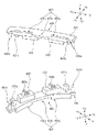
도 7은 제2 실시 예에 따른 스트랩과 하우징 결합 구조의 한 예를 나타낸 도면이며, 도 8은, 제2 실시 예에 따른 스트랩과 하우징 결합 구조의 일 단면을 나타낸 도면이다.7 is a view showing an example of a structure combining a strap and a housing according to a second embodiment, and FIG. 8 is a view showing a cross-section of a structure combining a strap and a housing according to the second embodiment.
도 5 내지 도 7을 참조하면, 제3 스트랩(531)은 제1 이격 홈(510b)이 형성된 제3 거치부(510)와 제2 이격 홈(420b)이 형성된 제4 거치부(400)를 포함할 수 있다. 앞서 설명한 도 5를 참조하면, 제3 거치부(510)는 제1 이격 홈(510b)을 기준으로 양 옆에 제1 거치 영역(510a) 및 제2 거치 영역(510c)을 포함할 수 있다. 제4 거치부(400)는 제2 이격 홈(420b)을 기준으로 양 옆에 제1 거치 레일(420a) 및 제2 거치 레일(420c)을 포함할 수 있다.Referring to FIGS. 5 to 7 , the
상기 하우징(120)은 측부에 적어도 하나의 스트랩 연결 구조(120a)를 포함할 수 있다. 상기 스트랩 연결 구조(120a)는 예컨대, 스트랩 접촉 영역(701) 및 경사면 영역(703)을 포함할 수 있다. 상기 스트랩 접촉 영역(701)은 주변보다 낮은(음각된) 홈 영역을 포함할 수 있다. 다양한 실시 예에 따르면, 상기 스트랩 접촉 영역(701)은 제3 날개부(511)가 안착되는 제1 스트랩 접촉 영역(710c), 제4 날개부(512)가 안착되는 제2 스트랩 접촉 영역(710a), 상기 제3 거치부(510)의 일부(예: 제1 이격 홈(510b)이 형성된 영역의 주변부), 상기 제4 거치부(400)의 일부(예: 제2 이격 홈(420b)이 형성된 영역의 주변부)가 접촉되는 제3 스트랩 접촉 영역(710c)을 포함할 수 있다. The
상기 경사면 영역(703)은 하우징(120)의 측부 중심을 기준으로 상측 및 하측으로 일정 경사면을 포함하고, 상측 및 하측에 각각 거치 행오버가 형성되어 제3 거치부(510) 및 제4 거치부(400)의 일부 구성들(예: 거치 영역들과 거치 레일들)이 장착될 수 있다. 상기 경사면 영역(703)은 예컨대, 상기 스트랩 접촉 영역들(710a, 710b, 710c)에 의해 나눠지는 제1 경사면 영역(703a) 및 제2 경사면 영역(703b)를 포함할 수 있다. 상기 제1 경사면 영역(703a)에는 예컨대, 제3 거치부(510)의 제1 거치 영역(510a)과 제4 거치부(400)의 제1 거치 레일(420a)이 인접되게 배치될 수 있다. 상기 제2 경사면 영역(703b)에는, 예컨대, 제3 거치부(510)의 제2 거치 영역(510c)과 제4 거치부(400)의 제2 거치 레일(420c)이 인접되게 배치될 수 있다. The
상기 하우징(120)의 스트랩 접촉 영역(701)에는 제3 스트랩(531)의 하우징 접촉 영역(705)이 접촉될 수 있다. 상기 제3 스트랩(531)의 하우징 접촉 영역(705)은 제3 날개부(511), 제4 날개부(512) 및 제1 이격 홈(510b)과 제2 이격 홈(420b)을 포함하는 제3 거치부(510)와 제4 거치부(400) 영역을 포함할 수 있다. 상기 하우징(120)의 경사면 영역(703)에는 제3 스트랩(531)의 경사면 접촉 영역(707)이 접촉될 수 있다. 상기 제3 스트랩(531)의 경사면 접촉 영역(707)은 제3 거치부(510)의 거치 영역들(510a, 510c)과 제4 거치부(400)의 거치 레일들(예: 420a, 420c)을 포함할 수 있다. The
도 8을 참조하면, 스트랩 접촉 영역(701)들과 하우징 접촉 영역(705)들이 접촉되는 영역에 대한 단면 A1-A1`, B1-B1`에서와 같이, 스트랩 접촉 영역(701)과 하우징 접촉 영역(705)은 밀접 접촉(또는 유동 공간이 제거)되어, 제3 스트랩(531)의 유동이 방지될 수 있다. Referring to FIG. 8 , the
상술한 제2 실시 예에 따른 제3 스트랩의 스트랩 체결부 구조는 앞서 도 1 내지 도 4에서 설명한 스트랩 중 적어도 하나에 적용될 수 있다. 또는, 도 1 내지 도 4에서 설명한 스트랩 구조 중 하나의 스트랩을 대체하여 적용될 수도 있다.The structure of the strap fastening part of the third strap according to the second embodiment described above may be applied to at least one of the straps described above with reference to FIGS. 1 to 4 . Alternatively, one of the strap structures described with reference to FIGS. 1 to 4 may be applied instead of one of the straps.
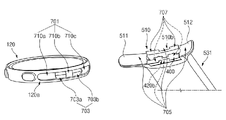
도 9는 제3 실시 예에 따른 스트랩 구조의 한 예를 나타낸 도면이다.9 is a view showing an example of a strap structure according to the third embodiment.
도 9에서, 901 상태는 제4 스트랩(931)의 제1 방향 관측 상태이며, 903 상태는 제4 스트랩(931)의 제2 방향 관측 상태이며, 905 상태는 제4 스트랩(931)의 제3 방향의 관측 상태이며, 907 상태는 905 상태의 A2-A2` 절단면의 한 예를 나타낸 것이다.9 , a
도 9를 참조하면, 한 실시 예에 따르면, 제4 스트랩(931)은 제2 스트랩 바디(931_1), 제4 스트랩 고정부(931_2), 제4 스트랩 체결부(939a)를 포함할 수 있다. 상기 제4 스트랩 고정부(931_2)의 적어도 일부는 상기 제2 스트랩 바디(931_1)의 일부에 대응할 수 있다. 상기 제2 스트랩 바디(931_1)는 앞서 도 1 내지 도 6에서 설명한 제1 스트랩(131)의 스트랩 숏 바디(131_1) 및 제2 스트랩(132)의 스트랩 롱 바디(132_1) 중 적어도 하나에 대응할 수 있다. 제2 스트랩 바디(931_1)의 -x축 방향의 가장자리에는 제4 스트랩 고정부(931_2)가 배치될 수 있다. 상기 제4 스트랩 고정부(931_2)는 제4 스트랩 체결부(939a)의 적어도 일부를 고정할 수 있다. 제4 스트랩 고정부(931_2)는 앞서 도 1 내지 도 6에서 설명한 제1 스트랩 고정부(131_2)와 동일 또는 유사한 구조를 포함할 수 있다. 제4 스트랩 고정부(931_2)는 거치 바디(920)가 배치되는 안착 영역, 상기 안착 영역을 기준으로 양측으로 배치되는 제5 고정부(931_2a) 및 제6 고정부(931_2b)를 포함할 수 있다. Referring to FIG. 9 , according to an embodiment, the
상기 제4 스트랩 체결부(939a)는 상기 제2 스트랩 바디(931_1)의 안착 영역에 배치되는 거치 바디(920), 상기 거치 바디(920)의 상측(예: z축 방향)에서 -x축 방향으로 연장된 제5 거치부(910), 상기 거치 바디(920)의 하측(예; -z축 방향)에서 -x축 방향으로 연장된 제6 거치부(970), 상기 거치 바디(920)의 일측 가장자리에서 y축과 -x축 사이의 대각선 방향으로 연장된 제1 날개부(911), 상기 거치 바디(920)의 타측 가장자리에서 -y축과 -x축 사이 대각선 방향으로 연장된 제2 날개부(912)를 포함할 수 있다. The fourth
상기 제1 날개부(911)는 상기 제5 고정부(931_2a)와 동일 또는 유사한 크기와 모양 및 배치 상태를 가질 수 있다. 한 실시 예에 따르면, 제1 날개부(911)와 제5 고정부(931_2a) 사이에는 접착층이 배치될 수 있다. 상기 제2 날개부(912)는 상기 제6 고정부(931_2b)와 동일 또는 유사한 크기와 모양 및 배치 상태를 가질 수 있다. 한 실시 예에 따르면, 제2 날개부(912)와 제6 고정부(931_2b) 사이에는 접착층이 배치될 수 있다. 상기 제1 날개부(911)는 거치 바디(920)의 중심부를 기준으로 제2 날개부(912)와 대칭되게 배치될 수 있다. 제1 날개부(911) 및 제2 날개부(912)는 y축 및 -y축 방향으로 일정 곡률을 가지며 휘어진 형상으로 마련되며, -x축에서 볼 때 오목한 형상으로 마련될 수 있다. 상기 오목한 형상의 제1 날개부(911) 및 제2 날개부(912)는 하우징(120)의 스트랩 접촉 영역에 접촉될 수 있다. The
상기 제5 거치부(910)는 상기 거치 바디(920)의 상측(예: z축 방향의 끝단)에서 -x축 방향으로 연장되는 제1 기본 베이스(910a)와, 상기 제1 기본 베이스(910a)의 -x축 방향의 연장 부분 끝단에서 z축 방향 또는 -x축과 z축 사이의 대각선 방향으로 연장되고 하우징(120)의 경사면 영역에 접촉되는 거치 영역(910b)을 포함할 수 있다. 상기 제5 거치부(910)는 상기 제6 거치부(970)와 일정 거리 이격되게 배치될 수 있다.The
상기 제6 거치부(970)는 상기 거치 바디(920)의 하측(예: -z축 방향의 끝단)에서 제5 거치부(910)와 이격되면서 -x축 방향으로 연장되는 제2 기본 베이스(970a)와, 상기 제2 기본 베이스(970a)의 -x축 방향의 연장 부분 끝단에서 -x축 -z축 방향 사이의 대각선 방향으로 연장되는 거치 레일(970b)을 포함할 수 있다. 다양한 실시 예에 따르면, 상기 제2 기본 베이스(970a)는 상기 제5 거치부(910)가 형성된 상기 거치 바디(920)의 일측과 반대 부분에서 상기 제5 거치부(910)와 이격되며 상기 하우징 바디(122) 방향으로 연장되도록 배치되고, 상기 거치 레일(970b)은 상기 제2 기본 베이스(970a)의 끝단에서 하우징 바디(122)를 향하면서 일정 경사각을 가지도록 형성될 수 있다. 상기 제6 거치부(970)와 거치 바디(920) 사이에는 슬릿들(921a, 921b)이 형성될 수 있다. 상기 슬릿들(921a, 921b)은 거치 바디(920)와의 간섭을 제거하여, 제6 거치부(970)가 내측(예: z축 방향)으로 이동되도록 지원할 수 있다. The sixth mounting
상기 거치 레일(970b)과 상기 거치 영역(910b)은 x축 또는 -x축을 기준으로 서로 대칭되게 배치될 수 있다. 상기 제5 거치부(910)와 상기 제6 거치부(970) 사이의 이격 거리는 외부에서 가해지는 압력에 따라 제6 거치부(970)가 휘어지는 경우 달라질 수 있다. 예컨대, 외부에서 압력이 가해지는 동안 제5 거치부(910)와 제6 거치부(970) 사이의 이격 거리는 짧아지고, 상기 압력 공급이 해제되면, 제5 거치부(910)와 제6 거치부(970) 사이의 이격 거리는 지정된 간격으로 복원될 수 있다. The mounting
도 10은 제3 실시 예에 따른 스트랩 체결의 한 예를 나타낸 도면이다.10 is a view showing an example of strap fastening according to the third embodiment.
도 9 및 도 10을 참조하면, 한 실시 예에 따르면, 웨어러블 전자 장치(100)는 디스플레이(110), 하우징(120), 후면 커버(150) 및 제4 스트랩(931)을 포함할 수 있다. 상기 제4 스트랩(931)은 앞서 도 1에서 설명한 제1 스트랩(131) 또는 제2 스트랩(132) 중 적어도 하나를 대체할 수 있다. 상기 제4 스트랩(931)은 거치 바디(920)에 제5 거치부(910)와 제6 거치부(970)가 일체화된 형태로 마련되면서, 제5 거치부(910)와 제6 거치부(970)가 이격되게 배치되면서, -x축 방향으로 연장된 상태를 가질 수 있다. 상기 디스플레이(110), 하우징(120) 및 후면 커버(150)는 앞서 도 1 및 도 2에서 설명한 구조와 동일한 구조를 가질 수 있다. 상기 하우징(120)은 예컨대, 제1 거치 홈(127a) 및 제2 거치 홈(127b)이 도시된 하우징(120)의 중심부 수평선을 기준으로 상하 대각선 방향으로 대칭되게 배치될 수 있다. 9 and 10 , according to an embodiment, the wearable
1001 상태에서와 같이, 제6 거치부(970)를 가압하여 제5 거치부(910) 방향으로 누른 상태에서, 제5 거치부(910)를 제1 거치 홈(127a)에 삽입할 수 있다. 제5 거치부(910)의 거치 영역(910a)의 두께는 제1 거치 홈(127a)의 두께와 유사하거나 작게 형성될 수 있다. 제5 거치부(910)가 제1 거치 홈(127a)에 삽입되면서, 거치 영역(910a)의 적어도 일부는 제1 거치 행오버(124a) 내측과 접촉되도록 배치될 수 있다. As in the state 1001 , the fifth mounting
제5 거치부(910)가 제1 거치 홈(127a)에 삽입된 상태에서, 제6 거치부(970)를 제2 거치 홈(127b)이 형성된 경사면 방향으로 밀어 넣은 뒤, 제6 거치부(970)에 가해지는 압력을 해제하면, 1003 상태에서와 같이, 제6 거치부(970)의 거치 레일(970a)이 제2 거치 홈(127b)에 삽입될 수 있다. 이에 대응하여, 제6 거치부(970)의 거치 레일(970a)의 적어도 일부는 제2 거치 행오버(124b)의 내측과 접촉되도록 배치될 수 있다. 제6 거치부(970)의 거치 레일(970a)의 두께는 제2 거치 홈(127b)의 폭과 유사하거나 작게 형성될 수 있다. 다양한 실시 예에 따르면, 제5 거치부(910)의 거치 영역(910a)의 두께와 제6 거치부(970)의 거치 레일(970a)의 두께는 동일하게 형성될 수 있으며, 또는 거치 홈들(127a, 127b)의 크기에 따라 다르게 형성될 수 있다. 다양한 실시 예에 따르면, 거치 홈들(127a, 127b)의 폭이 동일하게 형성된 상태에서, 제5 거치부(910)의 거치 영역(910a)의 두께와 제6 거치부(970)의 거치 레일(970a)의 두께는 다르게 형성될 수 있다. 다양한 실시 예에 따르면, 거치 홈들(127a, 127b)의 폭이 다르게 형성될 수도 있다. In a state in which the fifth mounting
다양한 실시 예에 따르면, 상기 제5 거치부(910) 및 제6 거치부(970)는 앞서 도 5a및 5b에서 설명한 바와 같이, 중심부에 이격 홈이 형성된 구조를 채용할 수도 있다. According to various embodiments, as described above with reference to FIGS. 5A and 5B , the fifth holding
상술한 다양한 실시 예 중 한 실시 예에 따른 웨어러블 전자 장치는 하우징(120), 상기 하우징의 일측에 연결되는 스트랩(131)을 포함하고, 상기 하우징은, 외측 적어도 일부에 상기 스트랩이 체결되는 적어도 하나의 스트랩 연결 구조(120a)를 포함하고, 상기 적어도 하나의 스트랩 연결 구조는 하우징 바디(122), 상기 하우징 바디의 외측으로 형성되어 상기 스트랩의 일부가 삽입되는 개구(125), 수평 방향을 기준으로, 상기 개구에서 상기 하우징 바디의 내측 방향과 수직 방향 사이 제1 대각선 방향에 형성되는 제1 거치 홈(127a)과, 상기 수평 방향을 기준으로, 상기 개구에서 상기 하우징 바디의 내측 방향과 수직 방향 사이 제2 대각선 방향에 형성되며 상기 수직 방향으로 상기 제1 거치 홈에 대응되게 배치되는 제2 거치 홈(127b)을 포함하고, 상기 스트랩은 스트랩 바디(131_1), 상기 스트랩 바디 일측에 연결된 거치 바디(320), 상기 거치 바디의 일측 단부에서 상기 하우징의 내측 방향으로 돌출되며 상기 제1 거치 홈에 삽입되는 제1 거치부(310), 상기 거치 바디의 타측 단부에 배치되어 상기 제2 거치 홈에 삽입되는 제2 거치부(200)를 포함할 수 있다.The wearable electronic device according to one of the various embodiments described above includes a
다양한 실시 예에 따르면, 상기 제1 거치 홈은 상기 하우징 바디의 외측에서 내측 및 상측 방향으로 형성되며, 상기 수평 방향을 0도로 정의할 때, 상기 0도 보다 큰 경사도를 가지는 제1 경사면과, 상기 제1 경사면으로부터 상기 하우징 바디의 외측으로 일정 간격 이격되어 형성된 제1 거치 행오버를 포함할 수 있다.According to various embodiments, the first mounting groove is formed in the inner and upper directions from the outside of the housing body, and when the horizontal direction is defined as 0 degrees, a first inclined surface having an inclination greater than 0 degrees; It may include a first mounting hangover formed to be spaced apart from the first inclined surface to the outside of the housing body by a predetermined interval.
다양한 실시 예에 따르면, 상기 제2 거치 홈은 상기 하우징 바디의 외측에서 내측 및 하측 방향으로 상기 0도보다 작은 경사도를 가지는 제2 경사면과, 상기 제2 경사면으로부터 상기 하우징의 외측으로 일정 간격 이격되어 형성되고, 상기 개구를 기준으로 상기 제1 거치 행오버로부터 이격된 제2 거치 행오버를 포함할 수 있다.According to various embodiments, the second mounting groove is spaced apart from a second inclined surface having an inclination smaller than 0 degrees in the inner and lower directions from the outside of the housing body, and the second inclined surface to the outside of the housing by a predetermined distance. formed and may include a second mounting hangover spaced apart from the first mounting hangover with respect to the opening.
다양한 실시 예에 따르면, 상기 제1 경사면과 상기 제2 경사면의 경사도는 동일하게 형성될 수 있다.According to various embodiments, the inclination of the first inclined surface and the inclination of the second inclined surface may be the same.
다양한 실시 예에 따르면, 상기 제1 경사면의 밑단과 상기 제2 경사면의 윗단은 서로 연결될 수 있다.According to various embodiments, the lower end of the first inclined surface and the upper end of the second inclined surface may be connected to each other.
다양한 실시 예에 따르면, 상기 제1 거치 홈의 크기는 상기 제1 거치부의 끝단의 두께보다 크게 형성될 수 있다.According to various embodiments, the size of the first mounting groove may be formed to be larger than the thickness of the end of the first mounting portion.
다양한 실시 예에 따르면, 상기 개구의 크기는 상기 제1 거치부의 상측 끝단과 상기 제2 거치부의 하측 끝단 사이의 이격 거리보다 작게 형성될 수 있다.According to various embodiments, the size of the opening may be formed to be smaller than the separation distance between the upper end of the first mounting portion and the lower end of the second mounting portion.
다양한 실시 예에 따르면, 상기 개구의 크기는 상기 제2 거치부가 외부 압력에 의해 이동된 상태에서 상기 제1 거치부의상측 끝단과 상기 제2 거치부의 하측 끝단 사이의 이격 거리보다 크게 될 수 있다.According to various embodiments, the size of the opening may be greater than the separation distance between the upper end of the first holder and the lower end of the second holder in a state in which the second holder is moved by external pressure.
다양한 실시 예에 따르면, 상기 제1 거치부는 상기 거치 바디로부터 상기 하우징 내측 방향으로 연장된 기본 베이스, 상기 기본 베이스에서 상기 수평 방향과 상기 수직 방향 중 상측 방향 사이의 대각선 방향으로 연장되고 상기 제1 거치 홈 내에 삽입되는 거치 영역을 포함할 수 있다.According to various embodiments, the first mounting portion extends in a diagonal direction between the horizontal direction and the vertical direction from the basic base extending in the inner direction of the housing from the mounting body, the basic base, and the first mounting portion It may include a mounting area inserted into the groove.
다양한 실시 예에 따르면, 상기 제2 거치부는 일정 곡률을 가지며 형성된 거치 베이스, 상기 거치 베이스의 일측 가장자리 전면에서 수직 방향 중 하측 방향으로 연장된 거치 레일, 상기 거치 베이스의 후면에서 수직 방향 중 상측 방향으로 연장된 적어도 2개의 후크들과, 상기 후크들 사이에 배치된 탄성 고정 구조, 상기 탄성 고정 구조에 고정된 탄성 부재를 포함할 수 있다.According to various embodiments, the second mounting portion has a predetermined curvature and is formed in a mounting base, a mounting rail extending in a lower direction in a vertical direction from the front of one edge of the mounting base, and an upward direction in a vertical direction from the rear surface of the mounting base. It may include at least two extended hooks, an elastic fixing structure disposed between the hooks, and an elastic member fixed to the elastic fixing structure.
다양한 실시 예에 따르면, 상기 거치 바디는 상기 제2 거치부가 안착되는 거치 공간, 상기 제2 거치부의 탄성 부재가 접촉되는 거치부 바닥, 상기 제2 거치부의 후크들과 결합하는 거치 턱들을 포함할 수 있다.According to various embodiments, the mounting body may include a mounting space in which the second mounting unit is seated, a mounting unit bottom to which the elastic member of the second mounting unit is in contact, and mounting jaws coupled to the hooks of the second mounting unit. have.
다양한 실시 예에 따르면, 상기 거치 바디는 상기 거치 턱들에 형성된 가이드 홈들을 더 포함할 수 있다.According to various embodiments, the mounting body may further include guide grooves formed in the mounting jaws.
다양한 실시 예에 따르면, 상기 제2 거치부는 상기 후크들에 인접되게 배치되고 상기 가이드 홈들에 적어도 일부가 삽입되는 가이드 돌기들을 더 포함할 수 있다.According to various embodiments, the second mounting portion may further include guide protrusions disposed adjacent to the hooks and at least partially inserted into the guide grooves.
다양한 실시 예에 따르면, 상기 거치 바디는 상기 스트랩 고정부와 다른 재질로 형성될 수 있다.According to various embodiments, the mounting body may be formed of a material different from that of the strap fixing part.
다양한 실시 예에 따르면, 상기 제2 거치부는 상기 제1 거치부가 형성된 상기 거치 바디의 일측과 반대 부분에서 상기 제1 거치부와 이격되며 상기 하우징 바디 방향으로 연장된 제2 기본 베이스, 상기 제2 기본 베이스의 끝단에서 일정 경사각을 가지며 형성된 거치 레일을 포함할 수 있다.According to various embodiments, the second mounting portion is a second basic base spaced apart from the first mounting portion at a portion opposite to one side of the mounting body on which the first mounting portion is formed and extending in the direction of the housing body, the second basic It may include a mounting rail formed with a predetermined inclination angle at the end of the base.
다양한 실시 예에 따르면, 제1 거치부는 상기 제1 거치 홈의 일측에 삽입되는 제1 거치 영역, 상기 제1 거치 홈의 타측에 삽입되는 제2 거치 영역 및 상기 제1 거치 영역과 상기 제2 거치 영역 사이에 배치되는 빈 공간에 해당하는 제1 이격 홈을 포함할 수 있다.According to various embodiments, the first mounting portion includes a first mounting area inserted into one side of the first mounting groove, a second mounting area inserted into the other side of the first mounting groove, and the first mounting area and the second mounting area. A first spacing groove corresponding to an empty space disposed between the regions may be included.
다양한 실시 예에 따르면, 제2 거치부는 상기 제2 거치 홈의 일측에 삽입되는 제1 거치 레일, 상기 제2 거치 홈의 타측에 삽입되는 제2 거치 레일 및 상기 제2 거치 레일과 상기 제2 거치 레일 사이에 배치되는 빈 공간에 해당하는 제2 이격 홈을 포함할 수 있다.According to various embodiments, the second mounting portion includes a first mounting rail inserted into one side of the second mounting groove, a second mounting rail inserted into the other side of the second mounting groove, and the second mounting rail and the second mounting rail. A second spacing groove corresponding to an empty space disposed between the rails may be included.
다양한 실시 예에 따르면, 상기 스트랩 연결 구조는 상기 수평 방향을 기준으로 상기 제1 거치 홈 및 상기 제2 거치 홈의 일측에 형성된 제1 스트랩 접촉 영역, 상기 수평 방향을 기준으로 상기 제1 거치 홈 및 상기 제2 거치 홈의 타측에 형성된 제2 스트랩 접촉 영역을 더 포함할 수 있다.According to various embodiments, the strap connection structure may include a first strap contact area formed on one side of the first mounting groove and the second mounting groove in the horizontal direction, the first mounting groove in the horizontal direction, and It may further include a second strap contact area formed on the other side of the second mounting groove.
다양한 실시 예에 따르면, 상기 스트랩은 상기 거치 바디에서 제1 방향으로 연장되어 상기 제1 스트랩 접촉 영역에 안착되는 제1 날개부, 상기 거치 바디에서 제2 방향으로 연장되어 상기 제2 스트랩 접촉 영역에 안착되는 제2 날개부를 더 포함할 수 있다.According to various embodiments, the strap extends in a first direction from the mounting body to a first wing portion seated on the first strap contact area, and extends from the mounting body in a second direction to the second strap contact area. It may further include a second wing portion to be seated.
다양한 실시 예에 따르면, 상기 웨어러블 전자 장치는 상기 하우징 내측에 적어도 일부가 삽입되는 디스플레이를 더 포함할 수 있다. According to various embodiments of the present disclosure, the wearable electronic device may further include a display at least partially inserted into the housing.
다양한 실시 예에 따르면, 상기 웨어러블 전자 장치는 디스플레이를 더 포함하고, 상기 디스플레이는 상기 하우징 일측에 적어도 일부가 거치되어, 적어도 일부가 외부로 노출되는 것을 특징으로 한다.According to various embodiments of the present disclosure, the wearable electronic device may further include a display, and at least a portion of the display is mounted on one side of the housing so that at least a portion thereof is exposed to the outside.
상술한 다양한 실시 예 중 한 실시 예에 따른 스트랩 구조(또는 스트랩)는 하우징 일측에 연결되도록 구성되며, 스트랩 바디, 상기 스트랩 바디 일측에 연결된 거치 바디, 상기 거치 바디의 일측 단부에서 상기 하우징의 내측 방향으로 돌출되며, 상기 하우징의 수평 방향을 0도로 하며 상기 수직 방향을 90도 또는 -90도로 정의할 경우, 상기 하우징 내측 방향으로 상기 0도보다 크고 90도보다 작은 경사각을 가지며 상기 하우징 내측에 삽입되는 제1 거치부, 상기 거치 바디의 타측 단부에 배치되고 상기 0도보다 작고 -90도보다 큰 경사각을 가지며 상기 하우징 내측에 삽입되는 제2 거치부를 포함하고, 상기 제1 거치부와 상기 제2 거치부는 상기 수평 방향을 기준으로 상하 대칭될 수 있다.The strap structure (or strap) according to one of the various embodiments described above is configured to be connected to one side of the housing, and the strap body, the mounting body connected to one side of the strap body, and the inner direction of the housing from one end of the mounting body When the horizontal direction of the housing is 0 degrees and the vertical direction is defined as 90 degrees or -90 degrees, it has an inclination angle greater than 0 degrees and less than 90 degrees in the inner direction of the housing and is inserted into the housing. a first mounting part, a second mounting part disposed at the other end of the mounting body and having an inclination angle smaller than 0 degrees and larger than -90 degrees and inserted into the housing, the first mounting part and the second mounting part The portion may be vertically symmetrical with respect to the horizontal direction.
본 문서에서, "가진다", "가질 수 있다", "포함한다", 또는 "포함할 수 있다" 등의 표현은 해당 특징(예: 수치, 기능, 동작, 또는 부품 등의 구성요소)의 존재를 가리키며, 추가적인 특징의 존재를 배제하지 않는다.In this document, expressions such as "have", "may have", "includes", or "may include" refer to the presence of a corresponding characteristic (eg, a numerical value, function, operation, or component such as a part). and does not exclude the presence of additional features.
본 문서에서, "A 또는 B", "A 또는/및 B 중 적어도 하나", 또는 "A 또는/및 B 중 하나 또는 그 이상" 등의 표현은 함께 나열된 항목들의 모든 가능한 조합을 포함할 수 있다. 예를 들면, "A 또는 B", "A 및 B 중 적어도 하나", 또는 "A 또는 B 중 적어도 하나"는, (1) 적어도 하나의 A를 포함, (2) 적어도 하나의 B를 포함, 또는 (3) 적어도 하나의 A 및 적어도 하나의 B 모두를 포함하는 경우를 모두 지칭할 수 있다.In this document, expressions such as “A or B”, “at least one of A or/and B”, or “one or more of A or/and B” may include all possible combinations of the items listed together. . For example, "A or B", "at least one of A and B", or "at least one of A or B" means (1) includes at least one A, (2) includes at least one B; Or (3) it may refer to all cases including both at least one A and at least one B.
본 문서에서 사용된 "제1", "제2", "첫째", 또는 "둘째" 등의 표현들은 다양한 구성요소들을, 순서 및/또는 중요도에 상관없이 수식할 수 있고, 한 구성요소를 다른 구성요소와 구분하기 위해 사용될 뿐 해당 구성요소들을 한정하지 않는다. 예를 들면, 제1 사용자 기기와 제2 사용자 기기는, 순서 또는 중요도와 무관하게, 서로 다른 사용자 기기를 나타낼 수 있다. 예를 들면, 본 문서에 기재된 권리 범위를 벗어나지 않으면서 제1 구성요소는 제2 구성요소로 명명될 수 있고, 유사하게 제2 구성요소도 제1 구성요소로 바꾸어 명명될 수 있다.Expressions such as "first", "second", "first", or "second" used in this document may modify various elements, regardless of order and/or importance, and may modify one element to another. It is used only to distinguish it from the components, and does not limit the components. For example, the first user equipment and the second user equipment may represent different user equipment regardless of order or importance. For example, without departing from the scope of rights described in this document, a first component may be referred to as a second component, and similarly, the second component may also be renamed as a first component.
어떤 구성요소(예: 제1 구성요소)가 다른 구성요소(예: 제2 구성요소)에 "(기능적으로 또는 통신적으로) 연결되어((operatively or communicatively) coupled with/to)" 있다거나 "접속되어(connected to)" 있다고 언급된 때에는, 상기 어떤 구성요소가 상기 다른 구성요소에 직접적으로 연결되거나, 다른 구성요소(예: 제3 구성요소)를 통하여 연결될 수 있다고 이해되어야 할 것이다. 반면에, 어떤 구성요소(예: 제1 구성요소)가 다른 구성요소(예: 제2 구성요소)에 "직접 연결되어" 있다거나 "직접 접속되어" 있다고 언급된 때에는, 상기 어떤 구성요소와 상기 다른 구성요소 사이에 다른 구성요소(예: 제3 구성요소)가 존재하지 않는 것으로 이해될 수 있다.A component (eg, a first component) is "coupled with/to (operatively or communicatively)" to another component (eg, a second component) When referring to "connected to", it should be understood that the certain element may be directly connected to the other element or may be connected through another element (eg, a third element). On the other hand, when it is said that a component (eg, a first component) is "directly connected" or "directly connected" to another component (eg, a second component), the component and the It may be understood that other components (eg, a third component) do not exist between other components.
본 문서에서 사용된 표현 "~하도록 구성된(또는 설정된)(configured to)"은 상황에 따라, 예를 들면, "~에 적합한(suitable for)", "~하는 능력을 가지는(having the capacity to)", "~하도록 설계된(designed to)", "~하도록 변경된(adapted to)", "~하도록 만들어진(made to)", 또는 "~를 할 수 있는(capable of)"과 바꾸어 사용될 수 있다. 용어 "~하도록 구성(또는 설정)된"은 하드웨어적으로 "특별히 설계된(specifically designed to)"것만을 반드시 의미하지 않을 수 있다. 대신, 어떤 상황에서는, "~하도록 구성된 장치"라는 표현은, 그 장치가 다른 장치 또는 부품들과 함께 "~할 수 있는" 것을 의미할 수 있다. 예를 들면, 문구 "A, B, 및 C를 수행하도록 구성(또는 설정)된 프로세서"는 해당 동작을 수행하기 위한 전용 프로세서(예: 임베디드 프로세서), 또는 메모리 장치에 저장된 하나 이상의 소프트웨어 프로그램들을 실행함으로써, 해당 동작들을 수행할 수 있는 범용 프로세서(generic-purpose processor)(예: CPU 또는 application processor)를 의미할 수 있다.The expression "configured to (or configured to)" as used in this document, depending on the context, for example, "suitable for", "having the capacity to" It can be used interchangeably with "," "designed to", "adapted to", "made to", or "capable of". The term "configured (or set up to)" may not necessarily mean only "specifically designed to" in hardware. Instead, in some circumstances, the expression “a device configured to” may mean that the device is “capable of” with other devices or parts. For example, the phrase "a processor configured (or configured to perform) A, B, and C" executes a dedicated processor (eg, an embedded processor), or one or more software programs stored in a memory device, to perform the corresponding operations. By doing so, it may mean a generic-purpose processor (eg, a CPU or an application processor) capable of performing corresponding operations.
본 문서에서 사용된 용어들은 단지 특정한 실시 예를 설명하기 위해 사용된 것으로, 다른 실시 예의 범위를 한정하려는 의도가 아닐 수 있다. 단수의 표현은 문맥상 명백하게 다르게 뜻하지 않는 한, 복수의 표현을 포함할 수 있다. 기술적이거나 과학적인 용어를 포함해서 여기서 사용되는 용어들은 본 문서에 기재된 기술 분야에서 통상의 지식을 가진 자에 의해 일반적으로 이해되는 것과 동일한 의미를 가질 수 있다. 본 문서에 사용된 용어들 중 일반적인 사전에 정의된 용어들은 관련 기술의 문맥 상 가지는 의미와 동일 또는 유사한 의미로 해석될 수 있으며, 본 문서에서 명백하게 정의되지 않는 한, 이상적이거나 과도하게 형식적인 의미로 해석되지 않는다. 경우에 따라서, 본 문서에서 정의된 용어일지라도 본 문서의 실시 예들을 배제하도록 해석될 수 없다.Terms used in this document are only used to describe specific embodiments, and may not be intended to limit the scope of other embodiments. The singular expression may include the plural expression unless the context clearly dictates otherwise. Terms used herein, including technical or scientific terms, may have the same meanings as commonly understood by one of ordinary skill in the art described in this document. Among the terms used in this document, terms defined in a general dictionary may be interpreted with the same or similar meaning as the meaning in the context of the related art, and unless explicitly defined in this document, have an ideal or excessively formal meaning. not interpreted In some cases, even terms defined in this document cannot be construed to exclude embodiments of this document.
본 문서의 다양한 실시 예들에 따른 전자 장치는, 예를 들면, 스마트폰(smartphone), 태블릿 PC(tablet personal computer), 이동 전화기(mobile phone), 영상 전화기, 전자책 리더기(e-book reader), 데스크탑 PC (desktop PC), 랩탑 PC(laptop PC), 넷북 컴퓨터(netbook computer), 워크스테이션(workstation), 서버, PDA(personal digital assistant), PMP(portable multimedia player), MP3 플레이어, 모바일 의료기기, 카메라, 또는 웨어러블 장치(wearable device) 중 적어도 하나를 포함할 수 있다. 다양한 실시 예에 따르면 웨어러블 장치는 엑세서리 형(예: 시계, 반지, 팔찌, 발찌, 목걸이, 안경, 콘택트 렌즈, 또는 머리 착용형 장치(head-mounted-device(HMD)), 직물 또는 의류 일체 형(예: 전자 의복), 신체 부착 형(예: 스킨 패드(skin pad) 또는 문신), 또는 생체 이식 형(예: implantable circuit) 중 적어도 하나를 포함할 수 있다.An electronic device according to various embodiments of the present disclosure may include, for example, a smartphone, a tablet personal computer, a mobile phone, a video phone, an e-book reader, Desktop PC (desktop PC), laptop PC (laptop PC), netbook computer (netbook computer), workstation (workstation), server, PDA (personal digital assistant), PMP (portable multimedia player), MP3 player, mobile medical device, It may include at least one of a camera and a wearable device. According to various embodiments, the wearable device may be an accessory type (eg, a watch, ring, bracelet, anklet, necklace, eyeglasses, contact lens, or head-mounted-device (HMD)), a fabric or a clothing integral type ( For example, it may include at least one of an electronic garment), a body attachable type (eg a skin pad or a tattoo), or a bioimplantable type (eg, an implantable circuit).
어떤 실시 예들에서, 전자 장치는 가전 제품(home appliance)일 수 있다. 가전 제품은, 예를 들면, 텔레비전, DVD 플레이어(Digital Video Disk player), 오디오, 냉장고, 에어컨, 청소기, 오븐, 전자레인지, 세탁기, 공기 청정기, 셋톱 박스(set-top box), 홈 오토매이션 컨트롤 패널(home automation control panel), 보안 컨트롤 패널(security control panel), TV 박스(예: 삼성 HomeSync™, 애플TV™, 또는 구글 TV™), 게임 콘솔(예: Xbox™, PlayStation™), 전자 사전, 전자 키, 캠코더, 또는 전자 액자 중 적어도 하나를 포함할 수 있다.In some embodiments, the electronic device may be a home appliance. Home appliances are, for example, televisions, DVD players (Digital Video Disk players), audio systems, refrigerators, air conditioners, vacuum cleaners, ovens, microwave ovens, washing machines, air purifiers, set-top boxes, home automation Control panel (home automation control panel), security control panel (security control panel), TV box (e.g. Samsung HomeSync™, Apple TV™, or Google TV™), game console (e.g. Xbox™, PlayStation™), electronics It may include at least one of a dictionary, an electronic key, a camcorder, and an electronic picture frame.
다른 실시 예에서, 전자 장치는, 각종 의료기기(예: 각종 휴대용 의료측정기기(혈당 측정기, 심박 측정기, 혈압 측정기, 또는 체온 측정기 등), MRA(magnetic resonance angiography), MRI(magnetic resonance imaging), CT(computed tomography), 촬영기, 또는 초음파기 등), 네비게이션(navigation) 장치, 위성 항법 시스템(GNSS(Global Navigation Satellite System)), EDR(event data recorder), FDR(flight data recorder), 자동차 인포테인먼트(infotainment) 장치, 선박용 전자 장비(예: 선박용 항법 장치, 자이로 콤파스 등), 항공 전자기기(avionics), 보안 기기, 차량용 헤드 유닛(head unit), 산업용 또는 가정용 로봇, 금융 기관의 ATM(automatic teller's machine), 상점의 POS(point of sales), 또는 사물 인터넷 장치(internet of things)(예: 전구, 각종 센서, 전기 또는 가스 미터기, 스프링클러 장치, 화재경보기, 온도조절기(thermostat), 가로등, 토스터(toaster), 운동기구, 온수탱크, 히터, 보일러 등) 중 적어도 하나를 포함할 수 있다.In another embodiment, the electronic device may include various medical devices (eg, various portable medical measuring devices (eg, a blood glucose monitor, a heart rate monitor, a blood pressure monitor, or a body temperature monitor), magnetic resonance angiography (MRA), magnetic resonance imaging (MRI), CT (computed tomography), imager, or ultrasound machine, etc.), navigation device, global navigation satellite system (GNSS), event data recorder (EDR), flight data recorder (FDR), car infotainment ) devices, ship electronic equipment (e.g. ship navigation devices, gyro compasses, etc.), avionics, security devices, vehicle head units, industrial or domestic robots, automatic teller's machines (ATMs) in financial institutions. , point of sales (POS) in stores, or internet of things (e.g. light bulbs, sensors, electricity or gas meters, sprinkler devices, smoke alarms, thermostats, street lights, toasters) , exercise equipment, hot water tank, heater, boiler, etc.) may include at least one.
어떤 실시 예에 따르면, 전자 장치는 가구(furniture) 또는 건물/구조물의 일부, 전자 보드(electronic board), 전자 사인 수신 장치(electronic signature receiving device), 프로젝터(projector), 또는 각종 계측 기기(예: 수도, 전기, 가스, 또는 전파 계측 기기 등) 중 적어도 하나를 포함할 수 있다. 다양한 실시 예에서, 전자 장치는 전술한 다양한 장치들 중 하나 또는 그 이상의 조합일 수 있다. 어떤 실시 예에 따른 전자 장치는 플렉서블 전자 장치일 수 있다. 또한, 본 문서의 실시 예에 따른 전자 장치는 전술한 기기들에 한정되지 않으며, 기술 발전에 따른 새로운 전자 장치를 포함할 수 있다.According to some embodiments, the electronic device is a piece of furniture or a building/structure, an electronic board, an electronic signature receiving device, a projector, or various measuring devices (eg, water, electricity, gas, or a radio wave measuring device). In various embodiments, the electronic device may be a combination of one or more of the various devices described above. The electronic device according to an embodiment may be a flexible electronic device. In addition, the electronic device according to the embodiment of this document is not limited to the above-described devices, and may include a new electronic device according to technological development.
다양한 실시 예에 따른 모듈 또는 프로그램 모듈은 전술한 구성요소들 중 적어도 하나 이상을 포함하거나, 일부가 생략되거나, 또는 다른 구성요소를 더 포함할 수 있다. 다양한 실시 예에 따른, 모듈, 프로그램 모듈 또는 다른 구성요소에 의해 수행되는 동작들은 순차적, 병렬적, 반복적 또는 휴리스틱하게 실행되거나, 적어도 일부 동작이 다른 순서로 실행되거나, 생략되거나, 또는 다른 동작이 추가될 수 있다.A module or a program module according to various embodiments may include at least one or more of the above-described components, some may be omitted, or may further include other components. According to various embodiments, operations performed by modules, program modules, or other components are sequentially, parallelly, repetitively or heuristically executed, or at least some operations are executed in a different order, omitted, or other operations are added. can be
본 문서에 개시된 실시예는 개시된, 기술 내용의 설명 및 이해를 위해 제시된 것이며, 본 문서에서 기재된 기술의 범위를 한정하는 것은 아니다. 따라서, 본 문서의 범위는, 본 문서의 기술적 사상에 근거한 모든 변경 또는 다양한 다른 실시예를 포함하는 것으로 해석되어야 한다.The embodiments disclosed in this document are provided for explanation and understanding of the disclosed and technical content, and do not limit the scope of the disclosed technology. Accordingly, the scope of this document should be construed to include all modifications or various other embodiments based on the technical spirit of this document.
Claims (20)
상기 하우징의 일측에 연결되는 스트랩(131);을 포함하고,
상기 하우징은,
외측 적어도 일부에 상기 스트랩이 체결되는 적어도 하나의 스트랩 연결 구조(120a);를 포함하고,
상기 적어도 하나의 스트랩 연결 구조는
하우징 바디(122);
상기 하우징 바디의 외측으로 형성되어 상기 스트랩의 일부가 삽입되는 개구(125);
수평 방향을 기준으로, 상기 개구에서 상기 하우징 바디의 내측 방향과 수직 방향 사이 제1 대각선 방향에 형성되는 제1 거치 홈(127a)과,
상기 수평 방향을 기준으로, 상기 개구에서 상기 하우징 바디의 내측 방향과 수직 방향 사이 제2 대각선 방향에 형성되며 상기 수직 방향으로 상기 제1 거치 홈에 대응되게 배치되는 제2 거치 홈(127b)을 포함하고,
상기 스트랩은
스트랩 바디(131_1);
상기 스트랩 바디 일측에 연결된 거치 바디(320);
상기 거치 바디의 일측 단부에서 상기 하우징의 내측 방향으로 돌출되며 상기 제1 거치 홈에 삽입되는 제1 거치부(310);
상기 거치 바디의 타측 단부에 배치되어 상기 제2 거치 홈에 삽입되는 제2 거치부(200);를 포함하는 것을 특징으로 하는 웨어러블 전자 장치.housing 120;
and a strap 131 connected to one side of the housing;
The housing is
At least one strap connection structure (120a) to which the strap is fastened to at least a portion of the outside;
The at least one strap connection structure comprises:
housing body 122;
an opening 125 formed outside the housing body into which a part of the strap is inserted;
A first mounting groove (127a) formed in a first diagonal direction between the inner direction and the vertical direction of the housing body in the opening with respect to the horizontal direction;
a second mounting groove 127b formed in a second diagonal direction between the inner direction and the vertical direction of the housing body in the opening with respect to the horizontal direction and disposed to correspond to the first mounting groove in the vertical direction; do,
the strap is
strap body (131_1);
a mounting body 320 connected to one side of the strap body;
a first mounting part 310 protruding from one end of the mounting body in an inner direction of the housing and inserted into the first mounting groove;
and a second mounting part (200) disposed at the other end of the mounting body and inserted into the second mounting groove.
상기 제1 거치 홈은
상기 하우징 바디의 외측에서 내측 및 상측 방향으로 형성되며, 상기 수평 방향을 0도로 정의할 때, 상기 0도 보다 큰 경사도를 가지는 제1 경사면과,
상기 제1 경사면으로부터 상기 하우징 바디의 외측으로 일정 간격 이격되어 형성된 제1 거치 행오버를 포함하는 것을 특징으로 하는 웨어러블 전자 장치.According to claim 1,
The first mounting groove is
a first inclined surface formed in the inner and upper directions from the outside of the housing body and having an inclination greater than 0 degrees when the horizontal direction is defined as 0 degrees;
and a first mounting hangover formed to be spaced apart from the first inclined surface by a predetermined distance to the outside of the housing body.
상기 제2 거치 홈은
상기 하우징 바디의 외측에서 내측 및 하측 방향으로 상기 0도보다 작은 경사도를 가지는 제2 경사면과,
상기 제2 경사면으로부터 상기 하우징의 외측으로 일정 간격 이격되어 형성되고, 상기 개구를 기준으로 상기 제1 거치 행오버로부터 이격된 제2 거치 행오버를 포함하는 것을 특징으로 하는 웨어러블 전자 장치.3. The method of claim 2,
The second mounting groove is
a second inclined surface having an inclination smaller than 0 degrees from the outer side of the housing body to the inner and lower directions;
and a second mounting hangover spaced apart from the second inclined surface by a predetermined distance to the outside of the housing and spaced apart from the first mounting hangover based on the opening.
상기 제1 경사면과 상기 제2 경사면의 경사도는 동일한 것을 특징으로 하는 웨어러블 전자 장치.3. The method of claim 2,
The wearable electronic device, characterized in that the inclination of the first inclined surface and the second inclined surface are the same.
상기 제1 경사면의 밑단과 상기 제2 경사면의 윗단은 서로 연결되는 것을 특징으로 하는 웨어러블 전자 장치.3. The method of claim 2,
The wearable electronic device, characterized in that the lower end of the first inclined surface and the upper end of the second inclined surface are connected to each other.
상기 제1 거치 홈의 크기는 상기 제1 거치부의 끝단의 두께보다 크게 형성된 것을 특징으로 하는 웨어러블 전자 장치.According to claim 1,
The size of the first mounting groove is a wearable electronic device, characterized in that formed larger than the thickness of the end of the first mounting portion.
상기 개구의 크기는 상기 제1 거치부의 상측 끝단과 상기 제2 거치부의 하측 끝단 사이의 이격 거리보다 작게 형성된 것을 특징으로 하는 웨어러블 전자 장치.According to claim 1,
The size of the opening is formed to be smaller than the distance between the upper end of the first mounting portion and the lower end of the second mounting portion.
상기 개구의 크기는
상기 제2 거치부가 외부 압력에 의해 이동된 상태에서 상기 제1 거치부의상측 끝단과 상기 제2 거치부의 하측 끝단 사이의 이격 거리보다 큰 것을 특징으로 하는 웨어러블 전자 장치.According to claim 1,
The size of the opening is
The wearable electronic device characterized in that the separation distance between the upper end of the first holder and the lower end of the second holder is greater than the distance between the upper end of the first holder and the lower end of the second holder in a state in which the second holder is moved by external pressure.
상기 제1 거치부는
상기 거치 바디로부터 상기 하우징 내측 방향으로 연장된 기본 베이스;
상기 기본 베이스에서 상기 수평 방향과 상기 수직 방향 중 상측 방향 사이의 대각선 방향으로 연장되고 상기 제1 거치 홈 내에 삽입되는 거치 영역;을 포함하는 것을 특징으로 하는 웨어러블 전자 장치.According to claim 1,
The first holding part
a basic base extending from the mounting body in an inner direction of the housing;
and a mounting region extending from the basic base in a diagonal direction between the horizontal direction and an upper direction of the vertical direction and inserted into the first mounting groove.
상기 제2 거치부는
일정 곡률을 가지며 형성된 거치 베이스;
상기 거치 베이스의 일측 가장자리 전면에서 수직 방향 중 하측 방향으로 연장된 거치 레일;
상기 거치 베이스의 후면에서 수직 방향 중 상측 방향으로 연장된 적어도 2개의 후크들과,
상기 후크들 사이에 배치된 탄성 고정 구조;
상기 탄성 고정 구조에 고정된 탄성 부재;를 포함하는 것을 특징으로 하는 웨어러블 전자 장치.According to claim 1,
The second holding part
a mounting base formed with a certain curvature;
a mounting rail extending in a lower direction in a vertical direction from the front side of one edge of the mounting base;
At least two hooks extending upward in a vertical direction from the rear surface of the mounting base,
an elastic fixing structure disposed between the hooks;
and an elastic member fixed to the elastic fixing structure.
상기 거치 바디는
상기 제2 거치부가 안착되는 거치 공간;
상기 제2 거치부의 탄성 부재가 접촉되는 거치부 바닥;
상기 제2 거치부의 후크들과 결합하는 거치 턱들;을 포함하는 것을 특징으로 하는 웨어러블 전자 장치.11. The method of claim 10,
The mounting body is
a mounting space in which the second holding unit is seated;
a bottom of the cradle to which the elastic member of the second cradle is in contact;
and mounting jaws coupled to the hooks of the second mounting unit.
상기 거치 바디는
상기 거치 턱들에 형성된 가이드 홈들;을 더 포함하는 것을 특징으로 하는 웨어러블 전자 장치.12. The method of claim 11,
The mounting body is
The wearable electronic device further comprising; guide grooves formed in the mounting jaws.
상기 제2 거치부는
상기 후크들에 인접되게 배치되고 상기 가이드 홈들에 적어도 일부가 삽입되는 가이드 돌기들;을 더 포함하는 것을 특징으로 하는 웨어러블 전자 장치.13. The method of claim 12,
The second holding part
The wearable electronic device further comprising a; guide protrusions disposed adjacent to the hooks and at least partially inserted into the guide grooves.
상기 거치 바디는
상기 스트랩 고정부와 다른 재질로 형성되는 것을 특징으로 하는 웨어러블 전자 장치.According to claim 1,
The mounting body is
The wearable electronic device, characterized in that it is formed of a material different from that of the strap fixing part.
제1 거치부는
상기 제1 거치 홈의 일측에 삽입되는 제1 거치 영역;
상기 제1 거치 홈의 타측에 삽입되는 제2 거치 영역; 및
상기 제1 거치 영역과 상기 제2 거치 영역 사이에 배치되는 빈 공간에 해당하는 제1 이격 홈;을 포함하는 것을 특징으로 하는 웨어러블 전자 장치.According to claim 1,
the first cradle
a first mounting area inserted into one side of the first mounting groove;
a second mounting area inserted into the other side of the first mounting groove; and
and a first spacing groove corresponding to an empty space disposed between the first mounting area and the second mounting area.
제2 거치부는
상기 제2 거치 홈의 일측에 삽입되는 제1 거치 레일;
상기 제2 거치 홈의 타측에 삽입되는 제2 거치 레일; 및
상기 제2 거치 레일과 상기 제2 거치 레일 사이에 배치되는 빈 공간에 해당하는 제2 이격 홈;을 포함하고,
상기 스트랩 연결 구조는
상기 수평 방향을 기준으로 상기 제1 거치 홈 및 상기 제2 거치 홈의 일측에 형성된 제1 스트랩 접촉 영역;
상기 수평 방향을 기준으로 상기 제1 거치 홈 및 상기 제2 거치 홈의 타측에 형성된 제2 스트랩 접촉 영역;을 더 포함하는 것을 특징으로 하는 웨어러블 전자 장치.16. The method of claim 15,
the second cradle
a first mounting rail inserted into one side of the second mounting groove;
a second mounting rail inserted into the other side of the second mounting groove; and
a second spacing groove corresponding to an empty space disposed between the second mounting rail and the second mounting rail; and
The strap connection structure is
a first strap contact area formed at one side of the first mounting groove and the second mounting groove with respect to the horizontal direction;
The wearable electronic device further comprising a second strap contact area formed on the other side of the first mounting groove and the second mounting groove with respect to the horizontal direction.
디스플레이;를 더 포함하고,
상기 디스플레이는 상기 하우징 일측에 적어도 일부가 거치되어, 적어도 일부가 외부로 노출되는 것을 특징으로 하는 웨어러블 전자 장치.According to claim 1,
Display; further comprising,
At least a portion of the display is mounted on one side of the housing, and at least a portion of the display is exposed to the outside.
상기 제2 거치부는
상기 제1 거치부가 형성된 상기 거치 바디의 일측과 반대 부분에서 상기 제1 거치부와 이격되며 상기 하우징 바디 방향으로 연장된 제2 기본 베이스;
상기 제2 기본 베이스의 끝단에서 일정 경사각을 가지며 형성된 거치 레일;을 포함하는 것을 특징으로 하는 웨어러블 전자 장치.According to claim 1,
The second holding part
a second basic base spaced apart from the first mounting portion at a portion opposite to one side of the mounting body on which the first mounting portion is formed and extending in the direction of the housing body;
and a mounting rail formed with a predetermined inclination angle from an end of the second basic base.
상기 스트랩은
상기 거치 바디에서 제1 방향으로 연장되어 상기 제1 스트랩 접촉 영역에 안착되는 제1 날개부;
상기 거치 바디에서 제2 방향으로 연장되어 상기 제2 스트랩 접촉 영역에 안착되는 제2 날개부;를 더 포함하는 것을 특징으로 하는 웨어러블 전자 장치.19. The method of claim 18,
the strap is
a first wing portion extending in a first direction from the mounting body and seated on the first strap contact area;
The wearable electronic device further comprising a second wing portion extending in a second direction from the mounting body and seated on the second strap contact area.
스트랩 바디;
상기 스트랩 바디 일측에 연결된 거치 바디;
상기 거치 바디의 일측 단부에서 상기 하우징의 내측 방향으로 돌출되며, 상기 하우징의 중심을 기준으로 수평 방향을 0도로 하며 수직 방향을 90도 또는 -90도로 정의할 경우, 상기 하우징 내측 방향으로 상기 0도보다 크고 90도보다 작은 경사각을 가지며 상기 하우징 내측에 삽입되는 제1 거치부;
상기 거치 바디의 타측 단부에 배치되고 상기 0도보다 작고 -90도보다 큰 경사각을 가지며 상기 하우징 내측에 삽입되는 제2 거치부;를 포함하고,
상기 제1 거치부와 상기 제2 거치부는 상기 수평 방향을 기준으로 상하 대칭되는 것을 특징으로 하는 스트랩 구조.In the strap structure connected to one side of the housing,
strap body;
a mounting body connected to one side of the strap body;
When one end of the mounting body protrudes in the inner direction of the housing, the horizontal direction is 0 degrees with respect to the center of the housing and the vertical direction is defined as 90 degrees or -90 degrees, the 0 degrees in the inner direction of the housing a first mounting part which is large and has an inclination angle smaller than 90 degrees and is inserted into the housing;
a second mounting part disposed at the other end of the mounting body and having an inclination angle smaller than 0 degrees and larger than -90 degrees and inserted into the housing; and
The strap structure, characterized in that the first mounting portion and the second mounting portion are vertically symmetrical with respect to the horizontal direction.
Priority Applications (4)
| Application Number | Priority Date | Filing Date | Title |
|---|---|---|---|
| KR1020210030232A KR20220126080A (en) | 2021-03-08 | 2021-03-08 | Strap structure connected to housing and wearable electronic device including the same |
| PCT/KR2022/000257 WO2022191399A1 (en) | 2021-03-08 | 2022-01-06 | Strap structure connected to housing, and wearable electronic device comprising same |
| EP22767296.1A EP4246248A1 (en) | 2021-03-08 | 2022-01-06 | Strap structure connected to housing, and wearable electronic device comprising same |
| US18/329,146 US20230305594A1 (en) | 2021-03-08 | 2023-06-05 | Strap structure connected to housing, and wearable electronic device comprising same |
Applications Claiming Priority (1)
| Application Number | Priority Date | Filing Date | Title |
|---|---|---|---|
| KR1020210030232A KR20220126080A (en) | 2021-03-08 | 2021-03-08 | Strap structure connected to housing and wearable electronic device including the same |
Publications (1)
| Publication Number | Publication Date |
|---|---|
| KR20220126080A true KR20220126080A (en) | 2022-09-15 |
Family
ID=83226877
Family Applications (1)
| Application Number | Title | Priority Date | Filing Date |
|---|---|---|---|
| KR1020210030232A KR20220126080A (en) | 2021-03-08 | 2021-03-08 | Strap structure connected to housing and wearable electronic device including the same |
Country Status (4)
| Country | Link |
|---|---|
| US (1) | US20230305594A1 (en) |
| EP (1) | EP4246248A1 (en) |
| KR (1) | KR20220126080A (en) |
| WO (1) | WO2022191399A1 (en) |
Family Cites Families (5)
| Publication number | Priority date | Publication date | Assignee | Title |
|---|---|---|---|---|
| JPH0174813U (en) * | 1987-11-10 | 1989-05-22 | ||
| US9894964B2 (en) * | 2014-08-11 | 2018-02-20 | Apple Inc. | Consumer product attachment systems having a locking assembly |
| DE102015222588A1 (en) * | 2015-11-16 | 2017-05-18 | Laboratorien THOMSON AG | Portable electronic device |
| KR101808051B1 (en) * | 2017-05-22 | 2017-12-13 | 주식회사 키위플러스 | Device for Connecting a Wrist Band |
| CN211354127U (en) * | 2019-12-31 | 2020-08-28 | 歌尔科技有限公司 | Watchband connection structure and wearable equipment |
-
2021
- 2021-03-08 KR KR1020210030232A patent/KR20220126080A/en unknown
-
2022
- 2022-01-06 EP EP22767296.1A patent/EP4246248A1/en active Pending
- 2022-01-06 WO PCT/KR2022/000257 patent/WO2022191399A1/en unknown
-
2023
- 2023-06-05 US US18/329,146 patent/US20230305594A1/en active Pending
Also Published As
| Publication number | Publication date |
|---|---|
| US20230305594A1 (en) | 2023-09-28 |
| EP4246248A1 (en) | 2023-09-20 |
| WO2022191399A1 (en) | 2022-09-15 |
Similar Documents
| Publication | Publication Date | Title |
|---|---|---|
| KR102396167B1 (en) | Flexible electronic device | |
| US10261541B2 (en) | Curved body and wearable device therewith | |
| CN113241009B (en) | Electronic device and foldable display device | |
| KR102500141B1 (en) | Strap with improved fastening structure and wearable electronic device including the same | |
| EP3329661B1 (en) | Electronic device including input apparatus | |
| CN108268095B (en) | Electronic device | |
| KR20180024632A (en) | Electronic device including a waterproof structure | |
| CN108668522A (en) | Wireless charging device | |
| KR102611125B1 (en) | Electronic device with curved window | |
| CN107666040B (en) | Head-mounted device | |
| KR102444053B1 (en) | Electronic device with shield structure | |
| CN108736282B (en) | Electronic device with deployable connector module | |
| KR102288460B1 (en) | Electronic device including component separation structure | |
| KR20170099626A (en) | Side key and electronic device including the same | |
| KR20170022567A (en) | Contact Structure and Contact device, and electronic Device including the same | |
| KR20220126080A (en) | Strap structure connected to housing and wearable electronic device including the same | |
| US20200237295A1 (en) | Method for calculating recovery index based on rem sleep stage and electronic device thereof | |
| US11500202B2 (en) | Head mounted device | |
| KR102122349B1 (en) | Curved Display and Electronic Device including the same | |
| KR20160034683A (en) | Card connector and electronic device therewith | |
| KR102545610B1 (en) | Electronic device with large capacity battery | |
| US10237988B2 (en) | Electronic device | |
| CN107250926B (en) | Electronic device | |
| KR20240017256A (en) | Electronic apparatus | |
| KR20230111125A (en) | Electronic device including battery |