KR20220124751A - Batteries and related devices, manufacturing methods and manufacturing devices - Google Patents
Batteries and related devices, manufacturing methods and manufacturing devices Download PDFInfo
- Publication number
- KR20220124751A KR20220124751A KR1020227026951A KR20227026951A KR20220124751A KR 20220124751 A KR20220124751 A KR 20220124751A KR 1020227026951 A KR1020227026951 A KR 1020227026951A KR 20227026951 A KR20227026951 A KR 20227026951A KR 20220124751 A KR20220124751 A KR 20220124751A
- Authority
- KR
- South Korea
- Prior art keywords
- protrusion
- battery
- adhesive
- battery cell
- sidewall
- Prior art date
Links
- 238000004519 manufacturing process Methods 0.000 title claims abstract description 83
- 239000000853 adhesive Substances 0.000 claims abstract description 277
- 230000001070 adhesive effect Effects 0.000 claims abstract description 277
- 230000007246 mechanism Effects 0.000 claims abstract description 269
- 238000002955 isolation Methods 0.000 claims abstract description 175
- 230000009467 reduction Effects 0.000 claims abstract description 26
- 238000000034 method Methods 0.000 claims description 76
- 230000006837 decompression Effects 0.000 claims description 36
- 230000008569 process Effects 0.000 claims description 26
- 239000012530 fluid Substances 0.000 claims description 10
- 230000002093 peripheral effect Effects 0.000 claims description 9
- 239000012815 thermoplastic material Substances 0.000 claims description 7
- 238000002844 melting Methods 0.000 claims description 5
- 230000008018 melting Effects 0.000 claims description 5
- 239000011247 coating layer Substances 0.000 claims description 3
- 230000001105 regulatory effect Effects 0.000 claims 1
- 238000013461 design Methods 0.000 description 28
- 238000006722 reduction reaction Methods 0.000 description 23
- HBBGRARXTFLTSG-UHFFFAOYSA-N Lithium ion Chemical compound [Li+] HBBGRARXTFLTSG-UHFFFAOYSA-N 0.000 description 16
- 229910001416 lithium ion Inorganic materials 0.000 description 16
- 239000000463 material Substances 0.000 description 16
- 230000000903 blocking effect Effects 0.000 description 15
- 230000006870 function Effects 0.000 description 15
- 239000010410 layer Substances 0.000 description 15
- 238000009434 installation Methods 0.000 description 12
- 239000000126 substance Substances 0.000 description 10
- 230000000694 effects Effects 0.000 description 9
- 230000004888 barrier function Effects 0.000 description 7
- 239000007773 negative electrode material Substances 0.000 description 7
- 239000007774 positive electrode material Substances 0.000 description 7
- 230000008901 benefit Effects 0.000 description 6
- 239000010408 film Substances 0.000 description 6
- 239000011248 coating agent Substances 0.000 description 5
- 238000000576 coating method Methods 0.000 description 5
- 239000002826 coolant Substances 0.000 description 5
- 238000001816 cooling Methods 0.000 description 5
- 239000003792 electrolyte Substances 0.000 description 5
- 238000005516 engineering process Methods 0.000 description 5
- 230000002452 interceptive effect Effects 0.000 description 5
- 230000002411 adverse Effects 0.000 description 4
- 238000010586 diagram Methods 0.000 description 4
- 238000012545 processing Methods 0.000 description 4
- 230000001681 protective effect Effects 0.000 description 4
- 239000010409 thin film Substances 0.000 description 4
- LYCAIKOWRPUZTN-UHFFFAOYSA-N Ethylene glycol Chemical compound OCCO LYCAIKOWRPUZTN-UHFFFAOYSA-N 0.000 description 3
- VYPSYNLAJGMNEJ-UHFFFAOYSA-N Silicium dioxide Chemical compound O=[Si]=O VYPSYNLAJGMNEJ-UHFFFAOYSA-N 0.000 description 3
- 239000000110 cooling liquid Substances 0.000 description 3
- 238000007599 discharging Methods 0.000 description 3
- 229910000625 lithium cobalt oxide Inorganic materials 0.000 description 3
- BFZPBUKRYWOWDV-UHFFFAOYSA-N lithium;oxido(oxo)cobalt Chemical compound [Li+].[O-][Co]=O BFZPBUKRYWOWDV-UHFFFAOYSA-N 0.000 description 3
- -1 polypropylene Polymers 0.000 description 3
- 229920001296 polysiloxane Polymers 0.000 description 3
- 230000001846 repelling effect Effects 0.000 description 3
- 239000000741 silica gel Substances 0.000 description 3
- 229910002027 silica gel Inorganic materials 0.000 description 3
- WHXSMMKQMYFTQS-UHFFFAOYSA-N Lithium Chemical compound [Li] WHXSMMKQMYFTQS-UHFFFAOYSA-N 0.000 description 2
- 239000004698 Polyethylene Substances 0.000 description 2
- 239000004743 Polypropylene Substances 0.000 description 2
- 238000004026 adhesive bonding Methods 0.000 description 2
- 239000002981 blocking agent Substances 0.000 description 2
- 239000007767 bonding agent Substances 0.000 description 2
- 238000006243 chemical reaction Methods 0.000 description 2
- 230000001066 destructive effect Effects 0.000 description 2
- QHGJSLXSVXVKHZ-UHFFFAOYSA-N dilithium;dioxido(dioxo)manganese Chemical compound [Li+].[Li+].[O-][Mn]([O-])(=O)=O QHGJSLXSVXVKHZ-UHFFFAOYSA-N 0.000 description 2
- 230000005489 elastic deformation Effects 0.000 description 2
- 239000007789 gas Substances 0.000 description 2
- 239000007788 liquid Substances 0.000 description 2
- 229910052744 lithium Inorganic materials 0.000 description 2
- GELKBWJHTRAYNV-UHFFFAOYSA-K lithium iron phosphate Chemical compound [Li+].[Fe+2].[O-]P([O-])([O-])=O GELKBWJHTRAYNV-UHFFFAOYSA-K 0.000 description 2
- 238000003754 machining Methods 0.000 description 2
- VNWKTOKETHGBQD-UHFFFAOYSA-N methane Chemical compound C VNWKTOKETHGBQD-UHFFFAOYSA-N 0.000 description 2
- 230000003647 oxidation Effects 0.000 description 2
- 238000007254 oxidation reaction Methods 0.000 description 2
- 238000004806 packaging method and process Methods 0.000 description 2
- 229920000573 polyethylene Polymers 0.000 description 2
- 229920001155 polypropylene Polymers 0.000 description 2
- 238000003825 pressing Methods 0.000 description 2
- 238000006479 redox reaction Methods 0.000 description 2
- 238000012827 research and development Methods 0.000 description 2
- 238000000926 separation method Methods 0.000 description 2
- 238000003860 storage Methods 0.000 description 2
- XLYOFNOQVPJJNP-UHFFFAOYSA-N water Substances O XLYOFNOQVPJJNP-UHFFFAOYSA-N 0.000 description 2
- 238000004804 winding Methods 0.000 description 2
- OKTJSMMVPCPJKN-UHFFFAOYSA-N Carbon Chemical compound [C] OKTJSMMVPCPJKN-UHFFFAOYSA-N 0.000 description 1
- RYGMFSIKBFXOCR-UHFFFAOYSA-N Copper Chemical compound [Cu] RYGMFSIKBFXOCR-UHFFFAOYSA-N 0.000 description 1
- 235000015842 Hesperis Nutrition 0.000 description 1
- 235000012633 Iberis amara Nutrition 0.000 description 1
- 229910052493 LiFePO4 Inorganic materials 0.000 description 1
- PXHVJJICTQNCMI-UHFFFAOYSA-N Nickel Chemical compound [Ni] PXHVJJICTQNCMI-UHFFFAOYSA-N 0.000 description 1
- 230000004308 accommodation Effects 0.000 description 1
- 239000002253 acid Substances 0.000 description 1
- 230000009471 action Effects 0.000 description 1
- 230000003213 activating effect Effects 0.000 description 1
- 239000003570 air Substances 0.000 description 1
- 229910052782 aluminium Inorganic materials 0.000 description 1
- XAGFODPZIPBFFR-UHFFFAOYSA-N aluminium Chemical compound [Al] XAGFODPZIPBFFR-UHFFFAOYSA-N 0.000 description 1
- 230000009286 beneficial effect Effects 0.000 description 1
- 238000005219 brazing Methods 0.000 description 1
- 229910052799 carbon Inorganic materials 0.000 description 1
- 239000010406 cathode material Substances 0.000 description 1
- 230000008859 change Effects 0.000 description 1
- 238000004891 communication Methods 0.000 description 1
- 239000000112 cooling gas Substances 0.000 description 1
- 229910052802 copper Inorganic materials 0.000 description 1
- 239000010949 copper Substances 0.000 description 1
- 238000005520 cutting process Methods 0.000 description 1
- 238000011161 development Methods 0.000 description 1
- 229920001971 elastomer Polymers 0.000 description 1
- 239000007772 electrode material Substances 0.000 description 1
- 239000003822 epoxy resin Substances 0.000 description 1
- 238000002474 experimental method Methods 0.000 description 1
- 238000000605 extraction Methods 0.000 description 1
- 239000006260 foam Substances 0.000 description 1
- 239000012634 fragment Substances 0.000 description 1
- 239000000446 fuel Substances 0.000 description 1
- 239000002737 fuel gas Substances 0.000 description 1
- 239000003502 gasoline Substances 0.000 description 1
- 239000000499 gel Substances 0.000 description 1
- 238000000227 grinding Methods 0.000 description 1
- 231100001261 hazardous Toxicity 0.000 description 1
- 238000010438 heat treatment Methods 0.000 description 1
- 230000006872 improvement Effects 0.000 description 1
- 238000009413 insulation Methods 0.000 description 1
- 238000010030 laminating Methods 0.000 description 1
- 150000002642 lithium compounds Chemical class 0.000 description 1
- 230000003446 memory effect Effects 0.000 description 1
- 229910052751 metal Inorganic materials 0.000 description 1
- 239000002184 metal Substances 0.000 description 1
- 229910052987 metal hydride Inorganic materials 0.000 description 1
- 239000000203 mixture Substances 0.000 description 1
- 238000012986 modification Methods 0.000 description 1
- 230000004048 modification Effects 0.000 description 1
- 239000003345 natural gas Substances 0.000 description 1
- 229910000652 nickel hydride Inorganic materials 0.000 description 1
- 230000035515 penetration Effects 0.000 description 1
- 229920000647 polyepoxide Polymers 0.000 description 1
- 229920002635 polyurethane Polymers 0.000 description 1
- 239000004814 polyurethane Substances 0.000 description 1
- 238000007789 sealing Methods 0.000 description 1
- 230000035939 shock Effects 0.000 description 1
- 229910052710 silicon Inorganic materials 0.000 description 1
- 239000010703 silicon Substances 0.000 description 1
- 230000008093 supporting effect Effects 0.000 description 1
- 238000003466 welding Methods 0.000 description 1
Images


Classifications
-
- B—PERFORMING OPERATIONS; TRANSPORTING
- B05—SPRAYING OR ATOMISING IN GENERAL; APPLYING FLUENT MATERIALS TO SURFACES, IN GENERAL
- B05D—PROCESSES FOR APPLYING FLUENT MATERIALS TO SURFACES, IN GENERAL
- B05D5/00—Processes for applying liquids or other fluent materials to surfaces to obtain special surface effects, finishes or structures
- B05D5/10—Processes for applying liquids or other fluent materials to surfaces to obtain special surface effects, finishes or structures to obtain an adhesive surface
-
- H—ELECTRICITY
- H01—ELECTRIC ELEMENTS
- H01M—PROCESSES OR MEANS, e.g. BATTERIES, FOR THE DIRECT CONVERSION OF CHEMICAL ENERGY INTO ELECTRICAL ENERGY
- H01M10/00—Secondary cells; Manufacture thereof
- H01M10/05—Accumulators with non-aqueous electrolyte
- H01M10/052—Li-accumulators
- H01M10/0525—Rocking-chair batteries, i.e. batteries with lithium insertion or intercalation in both electrodes; Lithium-ion batteries
-
- H—ELECTRICITY
- H01—ELECTRIC ELEMENTS
- H01M—PROCESSES OR MEANS, e.g. BATTERIES, FOR THE DIRECT CONVERSION OF CHEMICAL ENERGY INTO ELECTRICAL ENERGY
- H01M10/00—Secondary cells; Manufacture thereof
- H01M10/60—Heating or cooling; Temperature control
- H01M10/61—Types of temperature control
- H01M10/613—Cooling or keeping cold
-
- H—ELECTRICITY
- H01—ELECTRIC ELEMENTS
- H01M—PROCESSES OR MEANS, e.g. BATTERIES, FOR THE DIRECT CONVERSION OF CHEMICAL ENERGY INTO ELECTRICAL ENERGY
- H01M10/00—Secondary cells; Manufacture thereof
- H01M10/60—Heating or cooling; Temperature control
- H01M10/61—Types of temperature control
- H01M10/615—Heating or keeping warm
-
- H—ELECTRICITY
- H01—ELECTRIC ELEMENTS
- H01M—PROCESSES OR MEANS, e.g. BATTERIES, FOR THE DIRECT CONVERSION OF CHEMICAL ENERGY INTO ELECTRICAL ENERGY
- H01M10/00—Secondary cells; Manufacture thereof
- H01M10/60—Heating or cooling; Temperature control
- H01M10/62—Heating or cooling; Temperature control specially adapted for specific applications
- H01M10/623—Portable devices, e.g. mobile telephones, cameras or pacemakers
-
- H—ELECTRICITY
- H01—ELECTRIC ELEMENTS
- H01M—PROCESSES OR MEANS, e.g. BATTERIES, FOR THE DIRECT CONVERSION OF CHEMICAL ENERGY INTO ELECTRICAL ENERGY
- H01M10/00—Secondary cells; Manufacture thereof
- H01M10/60—Heating or cooling; Temperature control
- H01M10/62—Heating or cooling; Temperature control specially adapted for specific applications
- H01M10/625—Vehicles
-
- H—ELECTRICITY
- H01—ELECTRIC ELEMENTS
- H01M—PROCESSES OR MEANS, e.g. BATTERIES, FOR THE DIRECT CONVERSION OF CHEMICAL ENERGY INTO ELECTRICAL ENERGY
- H01M10/00—Secondary cells; Manufacture thereof
- H01M10/60—Heating or cooling; Temperature control
- H01M10/65—Means for temperature control structurally associated with the cells
- H01M10/653—Means for temperature control structurally associated with the cells characterised by electrically insulating or thermally conductive materials
-
- H—ELECTRICITY
- H01—ELECTRIC ELEMENTS
- H01M—PROCESSES OR MEANS, e.g. BATTERIES, FOR THE DIRECT CONVERSION OF CHEMICAL ENERGY INTO ELECTRICAL ENERGY
- H01M10/00—Secondary cells; Manufacture thereof
- H01M10/60—Heating or cooling; Temperature control
- H01M10/65—Means for temperature control structurally associated with the cells
- H01M10/655—Solid structures for heat exchange or heat conduction
- H01M10/6556—Solid parts with flow channel passages or pipes for heat exchange
-
- H—ELECTRICITY
- H01—ELECTRIC ELEMENTS
- H01M—PROCESSES OR MEANS, e.g. BATTERIES, FOR THE DIRECT CONVERSION OF CHEMICAL ENERGY INTO ELECTRICAL ENERGY
- H01M10/00—Secondary cells; Manufacture thereof
- H01M10/60—Heating or cooling; Temperature control
- H01M10/65—Means for temperature control structurally associated with the cells
- H01M10/656—Means for temperature control structurally associated with the cells characterised by the type of heat-exchange fluid
- H01M10/6567—Liquids
-
- H—ELECTRICITY
- H01—ELECTRIC ELEMENTS
- H01M—PROCESSES OR MEANS, e.g. BATTERIES, FOR THE DIRECT CONVERSION OF CHEMICAL ENERGY INTO ELECTRICAL ENERGY
- H01M50/00—Constructional details or processes of manufacture of the non-active parts of electrochemical cells other than fuel cells, e.g. hybrid cells
- H01M50/20—Mountings; Secondary casings or frames; Racks, modules or packs; Suspension devices; Shock absorbers; Transport or carrying devices; Holders
- H01M50/204—Racks, modules or packs for multiple batteries or multiple cells
- H01M50/207—Racks, modules or packs for multiple batteries or multiple cells characterised by their shape
- H01M50/209—Racks, modules or packs for multiple batteries or multiple cells characterised by their shape adapted for prismatic or rectangular cells
-
- H—ELECTRICITY
- H01—ELECTRIC ELEMENTS
- H01M—PROCESSES OR MEANS, e.g. BATTERIES, FOR THE DIRECT CONVERSION OF CHEMICAL ENERGY INTO ELECTRICAL ENERGY
- H01M50/00—Constructional details or processes of manufacture of the non-active parts of electrochemical cells other than fuel cells, e.g. hybrid cells
- H01M50/20—Mountings; Secondary casings or frames; Racks, modules or packs; Suspension devices; Shock absorbers; Transport or carrying devices; Holders
- H01M50/233—Mountings; Secondary casings or frames; Racks, modules or packs; Suspension devices; Shock absorbers; Transport or carrying devices; Holders characterised by physical properties of casings or racks, e.g. dimensions
- H01M50/24—Mountings; Secondary casings or frames; Racks, modules or packs; Suspension devices; Shock absorbers; Transport or carrying devices; Holders characterised by physical properties of casings or racks, e.g. dimensions adapted for protecting batteries from their environment, e.g. from corrosion
-
- H—ELECTRICITY
- H01—ELECTRIC ELEMENTS
- H01M—PROCESSES OR MEANS, e.g. BATTERIES, FOR THE DIRECT CONVERSION OF CHEMICAL ENERGY INTO ELECTRICAL ENERGY
- H01M50/00—Constructional details or processes of manufacture of the non-active parts of electrochemical cells other than fuel cells, e.g. hybrid cells
- H01M50/30—Arrangements for facilitating escape of gases
- H01M50/317—Re-sealable arrangements
- H01M50/325—Re-sealable arrangements comprising deformable valve members, e.g. elastic or flexible valve members
-
- H—ELECTRICITY
- H01—ELECTRIC ELEMENTS
- H01M—PROCESSES OR MEANS, e.g. BATTERIES, FOR THE DIRECT CONVERSION OF CHEMICAL ENERGY INTO ELECTRICAL ENERGY
- H01M50/00—Constructional details or processes of manufacture of the non-active parts of electrochemical cells other than fuel cells, e.g. hybrid cells
- H01M50/30—Arrangements for facilitating escape of gases
- H01M50/342—Non-re-sealable arrangements
- H01M50/3425—Non-re-sealable arrangements in the form of rupturable membranes or weakened parts, e.g. pierced with the aid of a sharp member
-
- H—ELECTRICITY
- H01—ELECTRIC ELEMENTS
- H01M—PROCESSES OR MEANS, e.g. BATTERIES, FOR THE DIRECT CONVERSION OF CHEMICAL ENERGY INTO ELECTRICAL ENERGY
- H01M50/00—Constructional details or processes of manufacture of the non-active parts of electrochemical cells other than fuel cells, e.g. hybrid cells
- H01M50/30—Arrangements for facilitating escape of gases
- H01M50/35—Gas exhaust passages comprising elongated, tortuous or labyrinth-shaped exhaust passages
- H01M50/367—Internal gas exhaust passages forming part of the battery cover or case; Double cover vent systems
-
- H—ELECTRICITY
- H01—ELECTRIC ELEMENTS
- H01M—PROCESSES OR MEANS, e.g. BATTERIES, FOR THE DIRECT CONVERSION OF CHEMICAL ENERGY INTO ELECTRICAL ENERGY
- H01M50/00—Constructional details or processes of manufacture of the non-active parts of electrochemical cells other than fuel cells, e.g. hybrid cells
- H01M50/30—Arrangements for facilitating escape of gases
- H01M50/375—Vent means sensitive to or responsive to temperature
-
- H—ELECTRICITY
- H01—ELECTRIC ELEMENTS
- H01M—PROCESSES OR MEANS, e.g. BATTERIES, FOR THE DIRECT CONVERSION OF CHEMICAL ENERGY INTO ELECTRICAL ENERGY
- H01M50/00—Constructional details or processes of manufacture of the non-active parts of electrochemical cells other than fuel cells, e.g. hybrid cells
- H01M50/50—Current conducting connections for cells or batteries
- H01M50/572—Means for preventing undesired use or discharge
- H01M50/584—Means for preventing undesired use or discharge for preventing incorrect connections inside or outside the batteries
- H01M50/59—Means for preventing undesired use or discharge for preventing incorrect connections inside or outside the batteries characterised by the protection means
- H01M50/593—Spacers; Insulating plates
-
- H—ELECTRICITY
- H01—ELECTRIC ELEMENTS
- H01M—PROCESSES OR MEANS, e.g. BATTERIES, FOR THE DIRECT CONVERSION OF CHEMICAL ENERGY INTO ELECTRICAL ENERGY
- H01M50/00—Constructional details or processes of manufacture of the non-active parts of electrochemical cells other than fuel cells, e.g. hybrid cells
- H01M50/60—Arrangements or processes for filling or topping-up with liquids; Arrangements or processes for draining liquids from casings
- H01M50/673—Containers for storing liquids; Delivery conduits therefor
- H01M50/682—Containers for storing liquids; Delivery conduits therefor accommodated in battery or cell casings
-
- H—ELECTRICITY
- H01—ELECTRIC ELEMENTS
- H01M—PROCESSES OR MEANS, e.g. BATTERIES, FOR THE DIRECT CONVERSION OF CHEMICAL ENERGY INTO ELECTRICAL ENERGY
- H01M2200/00—Safety devices for primary or secondary batteries
- H01M2200/10—Temperature sensitive devices
-
- H—ELECTRICITY
- H01—ELECTRIC ELEMENTS
- H01M—PROCESSES OR MEANS, e.g. BATTERIES, FOR THE DIRECT CONVERSION OF CHEMICAL ENERGY INTO ELECTRICAL ENERGY
- H01M2200/00—Safety devices for primary or secondary batteries
- H01M2200/20—Pressure-sensitive devices
-
- H—ELECTRICITY
- H01—ELECTRIC ELEMENTS
- H01M—PROCESSES OR MEANS, e.g. BATTERIES, FOR THE DIRECT CONVERSION OF CHEMICAL ENERGY INTO ELECTRICAL ENERGY
- H01M2220/00—Batteries for particular applications
- H01M2220/20—Batteries in motive systems, e.g. vehicle, ship, plane
-
- H—ELECTRICITY
- H01—ELECTRIC ELEMENTS
- H01M—PROCESSES OR MEANS, e.g. BATTERIES, FOR THE DIRECT CONVERSION OF CHEMICAL ENERGY INTO ELECTRICAL ENERGY
- H01M2220/00—Batteries for particular applications
- H01M2220/30—Batteries in portable systems, e.g. mobile phone, laptop
-
- H—ELECTRICITY
- H01—ELECTRIC ELEMENTS
- H01M—PROCESSES OR MEANS, e.g. BATTERIES, FOR THE DIRECT CONVERSION OF CHEMICAL ENERGY INTO ELECTRICAL ENERGY
- H01M50/00—Constructional details or processes of manufacture of the non-active parts of electrochemical cells other than fuel cells, e.g. hybrid cells
- H01M50/50—Current conducting connections for cells or batteries
- H01M50/543—Terminals
- H01M50/547—Terminals characterised by the disposition of the terminals on the cells
- H01M50/55—Terminals characterised by the disposition of the terminals on the cells on the same side of the cell
-
- Y—GENERAL TAGGING OF NEW TECHNOLOGICAL DEVELOPMENTS; GENERAL TAGGING OF CROSS-SECTIONAL TECHNOLOGIES SPANNING OVER SEVERAL SECTIONS OF THE IPC; TECHNICAL SUBJECTS COVERED BY FORMER USPC CROSS-REFERENCE ART COLLECTIONS [XRACs] AND DIGESTS
- Y02—TECHNOLOGIES OR APPLICATIONS FOR MITIGATION OR ADAPTATION AGAINST CLIMATE CHANGE
- Y02E—REDUCTION OF GREENHOUSE GAS [GHG] EMISSIONS, RELATED TO ENERGY GENERATION, TRANSMISSION OR DISTRIBUTION
- Y02E60/00—Enabling technologies; Technologies with a potential or indirect contribution to GHG emissions mitigation
- Y02E60/10—Energy storage using batteries
-
- Y—GENERAL TAGGING OF NEW TECHNOLOGICAL DEVELOPMENTS; GENERAL TAGGING OF CROSS-SECTIONAL TECHNOLOGIES SPANNING OVER SEVERAL SECTIONS OF THE IPC; TECHNICAL SUBJECTS COVERED BY FORMER USPC CROSS-REFERENCE ART COLLECTIONS [XRACs] AND DIGESTS
- Y02—TECHNOLOGIES OR APPLICATIONS FOR MITIGATION OR ADAPTATION AGAINST CLIMATE CHANGE
- Y02P—CLIMATE CHANGE MITIGATION TECHNOLOGIES IN THE PRODUCTION OR PROCESSING OF GOODS
- Y02P70/00—Climate change mitigation technologies in the production process for final industrial or consumer products
- Y02P70/50—Manufacturing or production processes characterised by the final manufactured product
Abstract
본 출원은 배터리 및 관련 장치, 제조 방법 및 제조 장치를 개시한다. 이 배터리는 배터리 셀, 부착 부재 및 격리 부재를 포함하며, 상기 배터리 셀은 감압 기구를 포함하고, 상기 감압 기구는 상기 배터리 셀의 내부 압력 또는 온도가 임계값에 도달할 때 작동되어 상기 내부 압력을 완화하도록 구성되며; 상기 부착 부재는 접착제에 의해 상기 배터리 셀에 부착되도록 구성되며; 그리고, 상기 격리 부재는 상기 부착 부재와 상기 감압 기구 사이에 상기 접착제가 도포되는 것을 방지하도록 구성된다. 격리 부재를 설치함으로써, 배터리 제조 과정에서 부착 부재와 감압 기구 사이에 접착제가 도포되는 것을 효과적으로 방지할 수 있다. 동시에 접착제의 도포 효율과 정확성을 향상시켜 배터리의 생산 효율을 향상시킬 수 있다. The present application discloses a battery and related apparatus, a manufacturing method, and a manufacturing apparatus. The battery includes a battery cell, an attachment member and an isolation member, wherein the battery cell includes a pressure reducing mechanism, wherein the pressure reduction mechanism is activated when an internal pressure or temperature of the battery cell reaches a threshold value to reduce the internal pressure configured to alleviate; the attachment member is configured to be attached to the battery cell by an adhesive; And, the isolating member is configured to prevent the adhesive from being applied between the attachment member and the pressure reducing mechanism. By providing the isolation member, it is possible to effectively prevent the adhesive from being applied between the attachment member and the pressure-reducing mechanism during the battery manufacturing process. At the same time, the application efficiency and accuracy of the adhesive can be improved, thereby improving the production efficiency of the battery.
Description
본 출원은 배터리 분야와 관련되며, 구체적으로 배터리 및 관련 장치, 제조 방법 및 제조 장치에 관한 것이다.This application relates to the field of batteries, and specifically relates to batteries and related devices, manufacturing methods, and manufacturing devices.
참고적으로, 본 출원은 2020년 07월 10일에 출원된 국제 출원 번호 PCT/CN2020/101443의 발명 명칭이 " 배터리 및 관련 장치, 제조 방법 및 제조 장치"인 특허 출원의 우선권을 주장하며, 그 전체 내용은 인용을 통해 여기에 포함된다. For reference, this application claims the priority of a patent application entitled "Battery and Related Apparatus, Manufacturing Method and Manufacturing Apparatus" in International Application No. PCT/CN2020/101443, filed on July 10, 2020, and The entire contents are incorporated herein by reference.
화학 배터리, 전화학 배터리, 전기화학 배터리 또는 전기화학 셀은 산화 환원 반응을 통해 양극 및 음극 활물질의 화학 에너지를 전기 에너지로 변환하는 유형의 장치를 말한다. 일반적인 산화 환원 반응과 달리 산화 및 환원 반응은 산화는 음극에서, 환원은 양극에서 따로따로 이루어지며, 전자의 득실은 외부 회로를 통해 이루어져 전류를 형성한다. 이는 모든 배터리의 필수 기능이다. 장기간의 연구 및 개발을 거쳐 화학 배터리는 다양한 제품이 출시되고 다양한 분야에 사용되고 있다. 큰 건물을 수용할 수 있는 거대한 장치부터 밀리미터 크기의 작은 유형도 있다. 현대 전자 기술의 발전은 화학 배터리에 대한 높은 요구 사항을 제시한다. 화학 배터리 기술의 모든 혁신은 전자 장치의 혁명적인 발전을 가져왔다. 세계의 많은 전기화학 과학자들은 전기 자동차의 동력으로 사용되는 화학 배터리 분야에 연구 개발 관심을 집중하고 있다. A chemical battery, electrochemical battery, electrochemical battery or electrochemical cell refers to a type of device that converts chemical energy of positive and negative active materials into electrical energy through redox reactions. Unlike general redox reactions, oxidation and reduction reactions are carried out separately at the cathode and at the anode for oxidation, and electrons gain and lose through an external circuit to form an electric current. This is an essential feature of any battery. After a long period of research and development, chemical batteries have been released and used in various fields. There are also large units that can accommodate large buildings, to smaller types in millimeters. Advances in modern electronic technology place high demands on chemical batteries. All innovations in chemical battery technology have revolutionized electronic devices. Many electrochemical scientists around the world are focusing their research and development attention on the field of chemical batteries used to power electric vehicles.
리튬 이온 배터리는 화학 배터리의 일종으로 소형, 고에너지 밀도, 고출력 밀도, 긴 사용 주기와 긴 저장 시간 등의 장점이 있어 일부 전자 장치, 전기 자동차, 전기 장난감 등에 널리 사용되고 있다. 예를 들어, 리튬 이온 배터리는 현재 휴대 전화, 노트북 컴퓨터, 배터리 자동차, 전기 자동차, 전기 비행기, 전기 선박, 전기 장난감 자동차, 전기 장난감 선박, 전기 장난감 비행기 및 전동 공구 등에 널리 사용된다. Lithium-ion batteries are a type of chemical battery and have advantages such as small size, high energy density, high power density, long use cycle and long storage time, and thus are widely used in some electronic devices, electric vehicles, and electric toys. For example, lithium ion batteries are currently widely used in mobile phones, notebook computers, battery cars, electric vehicles, electric planes, electric ships, electric toy cars, electric toy ships, electric toy planes and power tools.
리튬 이온 배터리 기술의 지속적인 발전으로 리튬 이온 배터리의 성능에 대한 요구 사항이 높아짐에 따라 리튬 이온 배터리가 다양한 설계 요소를 동시에 고려할 수 있기를 원하며, 그 중에서 리튬 이온 배터리의 안전 성능이 특히 중요하다.With the continuous development of lithium-ion battery technology, as the performance requirements of lithium-ion batteries increase, we want lithium-ion batteries to be able to consider various design factors at the same time, among which the safety performance of lithium-ion batteries is particularly important.
본 출원은 배터리의 안전 성능을 개선하기 위해 배터리 및 관련 장치, 제조 방법 및 제조 장치를 제안한다. The present application proposes a battery and related apparatus, a manufacturing method, and a manufacturing apparatus in order to improve the safety performance of the battery.
본 출원의 제1 측면에 따라 배터리를 제공하며, 이 배터리는 배터리 셀, 부착 부재 및 격리 부재를 포함하며, 상기 배터리 셀은 감압 기구를 포함하고, 상기 감압 기구는 상기 배터리 셀의 내부 압력 또는 온도가 임계값에 도달할 때 작동되어 상기 내부 압력을 완화하도록 구성되며; 상기 부착 부재는 접착제에 의해 상기 배터리 셀에 부착되도록 구성되며; 그리고, 상기 격리 부재는 상기 부착 부재와 상기 감압 기구 사이에 상기 접착제가 도포되는 것을 방지하도록 구성된다. According to a first aspect of the present application there is provided a battery, the battery comprising a battery cell, an attachment member and an isolation member, wherein the battery cell comprises a pressure reducing mechanism, wherein the pressure reducing mechanism is an internal pressure or temperature of the battery cell is configured to actuate and relieve the internal pressure when a threshold is reached; the attachment member is configured to be attached to the battery cell by an adhesive; And, the isolating member is configured to prevent the adhesive from being applied between the attachment member and the pressure reducing mechanism.
격리 부재를 설치함으로써, 배터리 제조 과정에서 부착 부재와 감압 기구 사이에 접착제가 도포되는 것을 효과적으로 방지할 수 있다. 동시에 접착제의 도포 효율과 정확성을 향상시켜 배터리의 생산 효율을 향상시킬 수 있다. By providing the isolation member, it is possible to effectively prevent the adhesive from being applied between the attachment member and the pressure-reducing mechanism during the battery manufacturing process. At the same time, the application efficiency and accuracy of the adhesive can be improved, thereby improving the production efficiency of the battery.
일부 실시예에서, 상기 감압 기구는 작동 영역을 갖고, 또한 상기 감압 기구는 상기 배터리 셀의 내부 압력 또는 온도가 임계값에 도달할 때 상기 작동 영역에 상기 내부 압력을 해제하기 위한 방출 통로를 형성하도록 구성된다. In some embodiments, the pressure reducing mechanism has an operating area, and the pressure reducing mechanism forms a discharge passage for releasing the inner pressure in the operating area when the internal pressure or temperature of the battery cell reaches a threshold value. is composed
감압 기구 작동시 작동 영역에 형성되는 방출 통로를 통해 배터리의 열폭주가 발생하는 경우 배터리 셀의 배출물을 형성된 방출 통로를 통해 외부로 배출되도록 유도하여 배터리의 안전 성능을 향상시킬 수 있다. When thermal runaway of the battery occurs through the discharge passage formed in the operation area when the decompression mechanism is operated, the discharge of the battery cell is induced to be discharged to the outside through the formed discharge passage, thereby improving the safety performance of the battery.
일부 실시예에서, 상기 격리 부재는 상기 접착제가 상기 작동 영역에 들어가는 것을 방지하기 위해 적어도 상기 작동 영역을 둘러싸도록 구성된다. In some embodiments, the isolation member is configured to surround at least the actuation area to prevent the adhesive from entering the actuation area.
이러한 방식으로 배치된 격리 부재는 배터리 셀의 내부 압력 또는 온도가 임계값에 도달할 때 접착제가 감압 기구의 정상적인 작동을 방해하는 것을 보다 확실하게 방지할 수 있고, 접착제가 유입되어 방출 통로를 차단하여 배터리 셀이 방출하는 배출물의 배출을 차단하는 것을 방지함으로써 배터리의 안전 성능을 더욱 향상시킨다. The isolation member disposed in this way can more reliably prevent the adhesive from interfering with the normal operation of the pressure reducing mechanism when the internal pressure or temperature of the battery cell reaches a critical value, and the adhesive can enter and block the discharge passage. It further improves the safety performance of the battery by preventing the discharge of the emissions emitted by the battery cells.
일부 실시예에서, 상기 격리 부재는 본체와 상기 본체의 표면으로부터 돌출 배치된 돌기부를 가지며, 상기 돌기부는 상기 감압 기구의 상기 작동 영역의 위치에 대응되게 배치되고, 또한 상기 돌기부는 상기 접착제가 상기 작동 영역에 들어가는 것을 방지하기 위해 적어도 상기 작동 영역을 둘러싸도록 구성된다. In some embodiments, the isolation member has a main body and a protrusion disposed protruding from the surface of the body, the protrusion disposed corresponding to a position of the operation area of the pressure reducing mechanism, and the protrusion may include a portion where the adhesive is applied to the actuation area. configured to surround at least the working area to prevent entry into the area.
이러한 배치는 배터리 제조 과정에서 간단하고 효과적인 방법으로 감압 기구의 표면에 접착제가 도포되는 것을 방지할 수 있어 접착제가 감압 기구의 작동을 방해하는 것을 방지할 수 있다. 또한, 이러한 배치는 실제 필요에 따라 격리 부재를 유연하게 설계할 수 있고, 그 중에서 단일의 격리 부재는 복수의 돌기부로 복수의 감압 기구의 작동 영역에 대해 접착제를 격리하는 효과를 달성할 수 있어 생산 비용 절감에 도움이 된다. This arrangement can prevent the adhesive from being applied to the surface of the pressure reducing mechanism in a simple and effective way during the battery manufacturing process, thereby preventing the adhesive from interfering with the operation of the pressure reducing mechanism. In addition, this arrangement makes it possible to flexibly design the isolation member according to actual needs, among which a single isolation member can achieve the effect of isolating the adhesive with respect to the working area of a plurality of pressure-sensitive mechanisms with a plurality of projections, so that the production It helps to cut costs.
일부 실시예에서, 상기 부착 부재는 회피 구조를 포함하며, 상기 회피 구조는 상기 감압 기구의 작동을 허용하는 공간을 제공하도록 구성되며; 또한, 상기 회피 구조와 상기 감압 기구 사이에는 회피 캐비티를 형성한다. In some embodiments, the attachment member includes an evasion structure, the evasion structure configured to provide a space allowing operation of the pressure reducing mechanism; Further, an avoidance cavity is formed between the avoidance structure and the pressure reduction mechanism.
이러한 회피 구조를 설정하면 감압 기구의 효과적인 작동에 필요한 작업 공간 또는 작동 공간을 보다 확실하게 확보할 수 있으며, 또한 회피 캐비티는 배터리 셀의 배출물을 위한 버퍼 공간을 제공할 수 있어 외부 구조 또는 구성 요소에 대한 배터리 셀의 충격 압력을 줄여 배터리의 안전 성능을 더욱 향상시킬 수 있다.By setting such an avoidance structure, it is possible to more reliably secure the working space or working space necessary for the effective operation of the pressure reducing mechanism, and also, the avoidance cavity can provide a buffer space for the discharge of the battery cell, so that the external structure or component is not affected. It is possible to further improve the safety performance of the battery by reducing the impact pressure of the battery cell.
일부 실시예에서, 상기 격리 부재는 상기 접착제가 상기 회피 캐비티에 들어가는 것을 방지하기 위해 적어도 상기 감압 기구와 대면하는 상기 회피 캐비티 일측의 주변 가장자리를 둘러싸도록 구성된다. In some embodiments, the isolation member is configured to surround a peripheral edge of at least one side of the avoidance cavity facing the pressure reducing mechanism to prevent the adhesive from entering the avoidance cavity.
이러한 방식으로 배치된 격리 부재는 회피 캐비티에 의해 제공되는 감압 기구의 효과적인 작동에 필요한 작업 공간 또는 작동 공간이 접착제에 의해 부분적으로 점유되지 않아 감압 기구의 정상적인 작동에 영향을 미치지 않는 것을 보장할 수 있고, 동시에, 배터리 셀이 배출물을 방출할 때 회피 캐비티가 완충 공간을 제공하는 역할을 하는 것을 보장할 수 있다.The isolation member disposed in this way can ensure that the working space or working space necessary for the effective operation of the pressure relief mechanism provided by the avoidance cavity is not partially occupied by the adhesive and does not affect the normal operation of the pressure reduction mechanism, and , at the same time, it can ensure that the avoidance cavity serves to provide a buffer space when the battery cell discharges its emissions.
일부 실시예에서, 상기 격리 부재는 본체와 상기 본체의 표면으로부터 돌출 배치된 돌기부를 가지며, 상기 돌기부는 상기 회피 캐비티의 위치와 대응하도록 배치되며, 또한 상기 돌기부는 상기 접착제가 상기 회피 캐비티에 들어가는 것을 방지하기 위해 적어도 상기 감압 기구와 대면하는 상기 회피 캐비티 일측의 주변 가장자리를 둘러싸도록 구성된다. In some embodiments, the isolating member has a body and a protrusion disposed protruding from the surface of the body, the protrusion disposed to correspond to a position of the avoidance cavity, and wherein the protrusion prevents the adhesive from entering the avoidance cavity configured to surround a peripheral edge of at least one side of the avoidance cavity facing the pressure reducing mechanism to prevent it.
이러한 배치는 배터리 제조 과정에서 간단하고 효과적인 방법으로 회피 캐비티에 접착제가 도포되어 회피 캐비티가 감압 기구의 효과적인 작동에 필요한 작동 공간을 제공할 수 없는 것을 방지할 수 있다. 또한, 이러한 배치는 실제 필요에 따라 격리 부재를 유연하게 설계할 수 있고, 그 중에서 단일의 격리 부재는 복수의 돌기부가 각각 복수의 회피 캐비티에 덮여 접착제를 격리하는 효과를 달성할 수 있어 생산 비용 절감에 도움이 된다. This arrangement can prevent the avoidance cavity from being unable to provide the working space required for effective operation of the pressure reducing mechanism by applying an adhesive to the avoidance cavity in a simple and effective manner during the battery manufacturing process. In addition, this arrangement can flexibly design the isolation member according to actual needs, among which a single isolation member has a plurality of protrusions each covered with a plurality of avoidance cavities to achieve the effect of isolating the adhesive, thereby reducing the production cost is helpful for
일부 실시예에서, 상기 돌기부의 높이는 상기 접착제의 소정의 도포 높이 이상이고, 또한 상기 배터리 셀이 상기 부착 부재에 부착되는 경우 상기 접착제와 일치하는 높이로 압축되도록 구성된다. In some embodiments, the height of the protrusion is greater than or equal to a predetermined application height of the adhesive, and is configured to be compressed to a height consistent with the adhesive when the battery cell is attached to the attachment member.
이러한 배치 방식은 돌기부가 상기 부착 부재와 상기 감압 기구 사이에 접착제가 도포되는 것을 효과적으로 방지할 수 있음을 보장한다. 동시에, 이는 격리 부재가 부착 부재와 감압 기구 사이의 신뢰성 있는 결합 및 감압 기구의 작동에 영향을 미치지 않도록 한다. 또한, 접착 표면에 도포된 접착제에 의해 배터리 셀 및 배터리의 부착 부재를 압착 또는 접합할 때, 돌기부는 접착제와 일치하는 높이로 압축될 수 있으므로, 돌기부는 배터리 셀과 배터리의 부착 부재의 접착 표면 둘 사이에 어떠한 틈도 남기지 않는다. 따라서 접착제가 감압 기구가 작동되고 또한 배출물의 통로를 형성하는 영역 외부에서 격리되는 것이 신뢰성 높게 보장될 수 있다. This arrangement method ensures that the protrusion can effectively prevent the adhesive from being applied between the attachment member and the pressure-sensitive mechanism. At the same time, this ensures that the isolation member does not affect the reliable engagement between the attachment member and the pressure reducing mechanism and the operation of the pressure reducing mechanism. In addition, when pressing or bonding the battery cell and the attachment member of the battery by the adhesive applied to the adhesive surface, the projection can be compressed to a height consistent with the adhesive, so that the projection is formed on both the bonding surfaces of the battery cell and the attachment member of the battery. Leave no gaps in between. It can thus be reliably ensured that the adhesive is isolated outside the area in which the pressure-relief mechanism is actuated and which also forms a passage for the discharge.
일부 실시예에서, 상기 돌기부는 블리스터 공정에 의해 상기 본체의 표면에 형성된다. In some embodiments, the protrusion is formed on the surface of the body by a blister process.
블리스터 공정을 채택함으로써, 필요한 격리 부재를 비교적 편리하고 저렴한 비용으로 가공 및 제조할 수 있으며, 특히 단일의 격리 부재에 다수의 돌기부를 형성하는 상황에서 블리스터 공정을 사용하여 시트 또는 필름을 기준으로 돌기부를 형성하는 것이 특히 유리하고 경제적이다. By adopting the blister process, the required isolation member can be processed and manufactured relatively conveniently and at low cost, especially in the situation of forming multiple protrusions on a single isolation member on a sheet or film basis using the blister process. It is particularly advantageous and economical to form the projection.
일부 실시예에서, 상기 돌기부는 제1 돌기부 및 제2 돌기부를 포함하고, 상기 제1돌기부는 상기 감압 기구의 위치와 대응되고, 상기 제2돌기부는 상기 제1돌기부의 둘레에 설치되고, 상기 제1돌기부와 상기 제2돌기부는 상기 부착 부재와 상기 감압 기구 사이에 상기 접착제가 도포되는 것을 방지하는데 사용된다. In some embodiments, the protrusion includes a first protrusion and a second protrusion, the first protrusion corresponds to a position of the decompression mechanism, and the second protrusion is provided around the first protrusion, and the second protrusion The first protrusion and the second protrusion are used to prevent the adhesive from being applied between the attachment member and the pressure-sensitive mechanism.
제1 돌기부 및 제2 돌기부의 돌출 높이는 접착제를 도포할 때와 같이 감압 기구와 부착 부재 사이의 공간에 접착제가 들어가 유입된 접착제가 감압 기구의 정상 작동을 방해하는 것을 방지하는 데 유리하다. 제2돌기부가 제1돌기부의 둘레에 설치되기 때문에 둘이 구조상 협력하여 접착제에 대한 다중 차단 역할을 하므로 접착제를 보다 효과적이고 확실하게 차단한다. The protruding heights of the first protrusion and the second protrusion are advantageous for preventing the adhesive from entering the space between the pressure-sensitive mechanism and the attachment member and interfering with the normal operation of the pressure-sensitive mechanism, such as when applying an adhesive. Since the second protrusion is installed around the first protrusion, the two work together structurally to act as a multi-blocking agent for the adhesive, thereby effectively and reliably blocking the adhesive.
일부 실시예에서, 상기 제1 돌기부와 상기 제2 돌기부 사이에 홈이 형성되며, 상기 홈은 상기 접착제의 적어도 일부를 수용하여, 상기 접착제가 상기 부착 부재와 상기 감압 기구 사이에 들어가는 것을 방지하는데 사용된다. In some embodiments, a groove is formed between the first protrusion and the second protrusion, wherein the groove is used to receive at least a portion of the adhesive to prevent the adhesive from entering between the attachment member and the pressure-sensitive mechanism. do.
홈은 접착제의 적어도 일부를 수용할 수 있으며, 이는 접착제를 위한 다른 장벽을 추가하는 것과 동일하다. 제2 돌기부가 그 주변 접착제가 제1 돌기부로 흐르는 것을 차단하는 경우, 제2 돌기부가 접착제를 차단하는 기능이 실패하면 홈은 제2 돌기부에서 넘친 일정량의 접착제를 저장할 수 있고, 이에 의해, 접착제가 감압 기구와 부착 부재 사이의 공간으로 더 흘러 들어가는 것이 방지된다. The groove may receive at least a portion of the adhesive, which is equivalent to adding another barrier for the adhesive. When the second protrusion blocks the adhesive around it from flowing to the first protrusion, if the function of the second protrusion to block the adhesive fails, the groove can store a certain amount of adhesive overflowing from the second protrusion, whereby the adhesive Further flow into the space between the pressure reducing mechanism and the attachment member is prevented.
일부 실시예에서, 상기 제2 돌기부는 제1 측벽, 제2 측벽 및 연결벽을 포함하며, 상기 제1 측벽은 상기 본체와 연결하는데 사용되고, 또한 상기 제1 측벽은 상기 제2 돌기부와 상기 홈이 공유하는 벽이며; 상기 제2 측벽은 상기 본체와 연결하는데 사용되고, 또한 상기 제2 측벽은 상기 제1 측벽과 대향되게 설치되며, 상기 연결벽은 상기 제1 측벽과 상기 제2 측벽을 연결하는데 사용된다. In some embodiments, the second protrusion includes a first sidewall, a second sidewall and a connecting wall, wherein the first sidewall is used to connect with the body, and wherein the first sidewall includes the second protrusion and the groove It is a shared wall; The second sidewall is used to connect with the main body, and the second sidewall is installed to face the first sidewall, and the connecting wall is used to connect the first sidewall and the second sidewall.
이러한 구조를 채택하면 접착제 차단 효과가 좋을 뿐만 아니라 가공에 필요한 금형이 비교적 간단하고 가공이 용이하며 비용이 저렴하다.Adopting such a structure not only has a good adhesive blocking effect, but also requires a relatively simple mold for processing, easy processing, and low cost.
일부 실시예에서, 상기 제1 측벽 및 상기 제2 측벽 중 적어도 하나는 제1 돌출부를 포함하고, 상기 제1 돌출부는 제1 방향을 따라 돌출되게 설치되며, 그 중에서 상기 제1 방향은 상기 제2 돌기부의 돌출 방향과 수직이다. In some embodiments, at least one of the first sidewall and the second sidewall includes a first protrusion, and the first protrusion is installed to protrude in a first direction, wherein the first direction is the second protrusion. It is perpendicular to the protrusion direction of the protrusion.
제1 돌출부를 설치함으로써 홈의 수용 체적을 증가시킬 수 있어 더 많은 접착제를 수용할 수 있고, 접착제가 부착 부재와 감압 기구 사이의 공간으로 들어가는 것을 방지할 수 있다.By providing the first protrusion, the receiving volume of the groove can be increased, so that more adhesive can be accommodated, and the adhesive can be prevented from entering the space between the attachment member and the pressure-sensitive mechanism.
일부 실시예에서, 상기 제1 측벽 및 상기 제2 측벽 중 적어도 하나는 상기 배터리 셀을 향하는 상기 부착 부재의 방향에 대해 경사지게 설치된다. In some embodiments, at least one of the first sidewall and the second sidewall is installed to be inclined with respect to a direction of the attachment member toward the battery cell.
제1 측벽을 경사지게 설치함으로써 홈의 수용 체적을 증가시킬 수 있어 더 많은 접착제를 수용할 수 있어, 접착제가 부착 부재와 감압 기구 사이에 들어가는 것을 방지할 수 있다. 제2 측벽을 경사지게 설치함으로써, 제2 돌기부의 주변에 접착제의 코팅 면적을 증가시킬 수 있고, 접합의 신뢰성을 확보할 수 있다. 또한, 제1 측벽 및/또는 제2 측벽을 경사지게 설치함으로써 제조 공정 동안 격리 부재의 금형 인발이 용이하다. By slanting the first sidewall, the receiving volume of the groove can be increased to accommodate more adhesive, thereby preventing the adhesive from entering between the attachment member and the pressure-sensitive mechanism. By installing the second sidewall inclined, the coating area of the adhesive around the second protrusion can be increased, and reliability of bonding can be secured. Further, by installing the first sidewall and/or the second sidewall at an angle, it is easy to extract the mold of the isolation member during the manufacturing process.
일부 실시예에서, 상기 연결벽은 제2 돌출부를 포함하고, 상기 제2 돌출부는 상기 배터리 셀을 향하는 상기 부착 부재의 방향을 따라 돌출되게 설치되며, 또는 상기 부착 부재를 향하는 상기 배터리 셀의 방향을 따라 돌출되게 설치된다. In some embodiments, the connection wall includes a second protrusion, and the second protrusion is installed to protrude along the direction of the attachment member toward the battery cell, or to change the direction of the battery cell toward the attachment member. installed to protrude along.
제2 돌출부의 설치는 연결벽의 표면을 요철로 만들어 접착제를 수용할 수 있는 공간을 형성한다. 이와 같이 접착제의 높이가 제2돌기부의 높이를 초과하여 제1돌기부를 향해 흐르는 경향이 있는 경우, 접착제는 먼저 연결벽 표면의 수용 공간에 남게 되는데, 이는 접착제가 제1 돌기부 방향으로 계속 흐르는 것을 방지하기 위해 다른 장벽을 추가하는 것과 동일하다.The installation of the second protrusion makes the surface of the connecting wall uneven to form a space for accommodating the adhesive. As such, when the height of the adhesive exceeds the height of the second protrusion and tends to flow toward the first protrusion, the adhesive first remains in the receiving space of the connecting wall surface, which prevents the adhesive from continuing to flow in the direction of the first protrusion It is equivalent to adding another barrier to
일부 실시예에서, 상기 제2 돌기부는 캐비티를 포함하며, 상기 제1 측벽, 상기 제2 측벽 및 상기 연결벽 중 적어도 하나에는 개구가 설치되며, 상기 개구는 상기 캐비티와 연통되어 상기 접착제의 적어도 일부가 상기 개구를 통해 상기 캐비티로 들어간다. In some embodiments, the second protrusion includes a cavity, and at least one of the first sidewall, the second sidewall and the connecting wall is provided with an opening, the opening communicating with the cavity and at least a portion of the adhesive enters the cavity through the opening.
제2 돌기부의 적어도 하나의 벽에 개구를 설치함으로써, 제2 돌기부 주위에 위치된 접착제는 개구를 통해 캐비티에 들어갈 수 있으므로, 제2 돌기부가 차지하는 공간을 충분히 활용함은 물론, 제2 돌기부 주변의 접착제를 감소시켜 접착제가 부착 부재와 감압 기구 사이의 공간으로 유입되는 것을 방지할 수 있다. By providing an opening in at least one wall of the second protrusion, the adhesive positioned around the second protrusion can enter the cavity through the opening, thereby fully utilizing the space occupied by the second protrusion, as well as providing an opening around the second protrusion. By reducing the adhesive, it is possible to prevent the adhesive from flowing into the space between the attachment member and the pressure-sensitive mechanism.
일부 실시예에서, 상기 제1 돌기부는 제3 측벽을 포함하며, 상기 제3 측벽은 상기 본체와 연결하는데 사용되고, 또한 상기 제3 측벽은 상기 제1 돌기부와 상기 홈이 공유하는 벽이고, 상기 제3 측벽은 상기 제1 측벽과 대향되게 설치되며; 그 중에서, 상기 제3 측벽은 제3 돌출부를 포함하고, 상기 제3 돌출부는 제1 방향을 따라 돌출되게 설치되며, 상기 제1 방향은 상기 제2 돌기부의 돌출 방향과 수직이며; 및/또는, 상기 제3 측벽은 상기 배터리 셀을 향하는 상기 부착 부재의 방향에 대해 경사지게 설치된다. In some embodiments, the first protrusion includes a third sidewall, the third sidewall is used to connect with the body, and the third sidewall is a wall shared between the first protrusion and the groove, 3 sidewalls are installed to face the first sidewalls; Among them, the third sidewall includes a third protrusion, and the third protrusion is installed to protrude in a first direction, wherein the first direction is perpendicular to the protrusion direction of the second protrusion; and/or, the third sidewall is installed to be inclined with respect to the direction of the attachment member toward the battery cell.
이러한 방식을 사용함으로써 홈의 수용 체적을 증가시킬 수 있어 더 많은 접착제를 수용할 수 있어, 접착제가 부착 부재와 감압 기구 사이에 들어가는 것을 효율적으로 방지할 수 있다. 또한, 이러한 방식은 제조 공정 동안 격리 부재의 금형 인발이 용이하다. By using this method, it is possible to increase the receiving volume of the groove to accommodate more adhesive, thereby effectively preventing the adhesive from entering between the attachment member and the pressure-reducing mechanism. In addition, this method facilitates mold extraction of the isolation member during the manufacturing process.
일부 실시예에서, 상기 제2돌기부의 폭은 1mm-8mm이다. In some embodiments, the width of the second protrusion is 1 mm-8 mm.
일부 실시예에서, 상기 제2 돌기부는 환형 구조이다. 제2 돌기부는 제2 돌기부의 외주에서 제1 돌기부로의 접착제의 흐름을 차단할 수 있다.In some embodiments, the second protrusion has an annular structure. The second protrusion may block the flow of the adhesive from the outer periphery of the second protrusion to the first protrusion.
일부 실시예에서, 상기 홈의 폭은 1mm-8mm이다.In some embodiments, the width of the groove is 1 mm-8 mm.
일부 실시예에서, 상기 제2 돌기부는 상기 본체의 표면에 부착되는 탄성 부재이다. 탄성 부재는 일정한 탄성 변형 능력을 가지며, 이는 접착제를 차단하는 제2 돌기부 역할을 하며 큰 설치 오차에 적응할 수 있다.In some embodiments, the second protrusion is an elastic member attached to the surface of the body. The elastic member has a certain elastic deformation ability, which serves as a second protrusion to block the adhesive and can adapt to a large installation error.
일부 실시예에서, 상기 돌기부는 제3 돌기부를 더 포함하고, 상기 제3 돌기부는 상기 제2 돌기부의 둘레에 설치된다. 제1 돌기부 주위에 설치된 돌기부가 많을수록 접착제에 대한 차단 효과가 더 좋다.In some embodiments, the protrusion further includes a third protrusion, and the third protrusion is provided around the second protrusion. The more protrusions provided around the first protrusion, the better the barrier effect on the adhesive.
일부 실시예에서, 상기 감압 기구와 대면하는 상기 돌기부의 벽에는 통공이 설치되며, 상기 통공은 상기 감압 기구가 작동될 때 상기 배터리 셀로부터의 배출물이 상기 격리 부재를 통과할 수 있도록 구성된다. In some embodiments, an aperture is provided in the wall of the protrusion facing the pressure reducing mechanism, the aperture configured to allow the discharge from the battery cell to pass through the isolation member when the pressure reduction mechanism is actuated.
제1 돌기부의 상부벽에 제공된 통공은 감압 기구의 작동을 위한 공간을 제공하고 또한 배출물의 통로를 형성할 수 있고, 또한, 통공은 제1 돌기부, 홈 및 제2 돌기부의 차단 기능이 실효될 때 접착제가 통공에 들어갈 수 있게 하여 접착제가 감압 기구와 접착되어 감압 기구의 순조로운 개방에 영향을 미치는 것을 방지한다.The through hole provided in the upper wall of the first protrusion provides a space for the operation of the pressure reducing mechanism and can also form a passage for the discharge, and the through hole is formed when the blocking function of the first protrusion, the groove and the second protrusion becomes invalid. Allowing the adhesive to enter the through hole prevents the adhesive from adhering to the pressure-sensitive mechanism and affecting the smooth opening of the pressure-sensitive mechanism.
일부 실시예에서, 상기 통공은 상기 감압 기구 둘레에 설치되어 상기 접착제가 상기 감압 기구와 상기 부착 부재 사이에 들어가는 것을 방지한다. 이러한 방식으로, 접착제와 감압 기구가 접착되어 감압 기구의 원활한 개방에 영향을 미치는 것을 방지한다.In some embodiments, the through hole is provided around the pressure reducing mechanism to prevent the adhesive from entering between the pressure reducing mechanism and the attachment member. In this way, the adhesive and the pressure-sensitive mechanism are prevented from adhering to affect the smooth opening of the pressure-sensitive mechanism.
일부 실시예에서, 상기 통공은 상기 작동 영역의 위치와 대응되도록 구성되며, 또한 상기 통공은 상기 작동 영역 둘레에 설치되어 상기 접착제가 상기 작동 영역과 상기 부착 부재 사이에 들어가는 것을 방지한다. 이러한 방식으로, 접착제와 감압 기구가 접착되어 감압 기구의 원활한 개방에 영향을 미치는 것을 방지한다. In some embodiments, the aperture is configured to correspond to a location of the actuation area, and the aperture is provided around the actuation area to prevent the adhesive from entering between the actuation area and the attachment member. In this way, the adhesive and the pressure-sensitive mechanism are prevented from adhering to affect the smooth opening of the pressure-sensitive mechanism.
일부 실시예에서, 상기 배터리는 복수의 배터리 셀을 포함하고, 상기 복수의 배터리 셀의 각 배터리 셀은 상기 감압 기구를 포함하며; 상기 격리 부재는 적어도 하나의 상기 돌기부를 포함하며; 그 중에서, 상기 돌기부는 상기 감압 기구와 일대일 대응되며, 또는 상기 돌기부는 적어도 2개의 상기 감압 기구와 대응된다. In some embodiments, the battery includes a plurality of battery cells, each battery cell of the plurality of battery cells includes the decompression mechanism; the isolation member comprises at least one said protrusion; Among them, the protrusion corresponds to the decompression mechanism one-to-one, or the protrusion corresponds to at least two of the decompression mechanisms.
이러한 방식을 사용하여, 격리 부재를 배터리의 부착 부재에 조립하는 과정이 더 간단하고, 동시에 복수의 돌기부를 이용하여 도포되거나 도포될 접착제를 상대적으로 독립적인 방식으로 배터리에 포함된 복수의 배터리 셀의 감압 기구 또는 그의 방출 영역으로부터 격리할 수 있다. 또한, 이것은 작업자가 접착제를 도포할 때 더 높은 효율로 접착제 도포를 적절하게 완료하는 데 도움이 될 수 있으므로 작업자가 접착제를 조심스럽게 도포하는 작업을 수행할 필요가 없으므로 배터리의 조립 비용 및 생산 비용이 감소된다. 돌기부가 2개 이상의 갑압 기구와 대응하는 경우 조립 정확도도 감소할 수 있고 더 큰 설치 오류를 수용할 수 있다.In this way, the process of assembling the isolation member to the attachment member of the battery is simpler, and at the same time, the adhesive to be applied or to be applied using the plurality of protrusions is applied to the plurality of battery cells included in the battery in a relatively independent manner. It can be isolated from the pressure reducing device or its discharge area. In addition, this can help the operator to properly complete the adhesive application with higher efficiency when applying the adhesive, eliminating the need for the operator to perform the task of carefully applying the adhesive, thereby reducing the assembly cost and production cost of the battery. is reduced If the protrusion corresponds to two or more pressure reducing mechanisms, the assembly accuracy may also decrease and a larger installation error may be accommodated.
일부 실시예에서, 상기 격리 부재는 상기 감압 기구가 작동될 때 상기 배터리 셀로부터의 배출물에 의해 파괴되도록 구성된다. In some embodiments, the isolation member is configured to be destroyed by the discharge from the battery cell when the pressure reduction mechanism is actuated.
이에 의해, 배터리 셀의 열폭주의 경우, 감압 기구의 작동으로 유출되는 배출물에 의해 격리 부재가 파괴되어 배출물이 유출되는 통로가 형성될 수 있으며, 이는 배터리의 안전성을 개선할 수 있다.Accordingly, in the case of thermal runaway of the battery cell, the isolation member may be destroyed by the discharge discharged by the operation of the decompression mechanism to form a passage through which the discharge flows, which may improve the safety of the battery.
일부 실시예에서, 상기 격리 부재는 용융점이 상기 배출물의 방출 온도보다 크지 않은 열가소성 재료로 만들어진다. In some embodiments, the isolation member is made of a thermoplastic material whose melting point is not greater than the discharge temperature of the effluent.
이러한 설계는 배터리 셀이 열폭주가 없는 일반 사용 상태에서 격리 부재가 상대적으로 높은 구조적 강도를 가질 수 있으며, 동시에 배터리 셀의 열폭주가 발생하는 경우 상대적으로 짧은 시간에 고온 고압 배출물에 의해 확실하게 파괴될 수 있으며, 또한 배출물이 배터리 셀로부터 빠르게 배출되게 한다. This design allows the isolation member to have relatively high structural strength in the normal use condition of the battery cell without thermal runaway, and at the same time, when thermal runaway of the battery cell occurs, it can be reliably destroyed by high-temperature and high-pressure discharge in a relatively short time. It can also cause the emissions to drain quickly from the battery cells.
일부 실시예에서, 상기 격리 부재는 그 위에 상기 접착제가 도포되는 것을 방지하기 위한 코팅층을 포함한다. 따라서, 격리 부재는 돌기부가 없는 구조로도 구현될 수 있다.In some embodiments, the isolation member includes a coating layer to prevent the adhesive from being applied thereon. Accordingly, the isolation member may be implemented with a structure without protrusions.
일부 실시예에서, 상기 부착 부재는 상기 배터리 셀의 온도를 조절하기 위해 유체를 수용하기 위한 열관리 부재를 포함한다. 열관리 부재를 설치함으로써 배터리 셀의 온도를 보다 유연하고 능동적으로 제어할 수 있으므로 배터리 셀의 열 폭주 위험을 줄일 수 있다.In some embodiments, the attachment member includes a thermal management member for receiving a fluid to regulate the temperature of the battery cell. By installing a thermal management member, the temperature of the battery cell can be more flexibly and actively controlled, thereby reducing the risk of thermal runaway of the battery cell.
일부 실시예에서, 상기 회피 구조는 상기 열관리 부재에 형성되고, 또한 상기 회피 구조는 회피 바닥벽과 상기 회피 캐비티를 둘러싸는 회피 측벽을 포함한다. 이러한 배치는 열관리 부재와 회피 구조의 설계를 간단한 방식과 낮은 비용으로 실현하며, 회피 구조를 열관리 부재에 통합하여 공간 점유를 줄이는 데 도움이 되어 배터리의 에너지 밀도를 향상시키는 데 도움이 된다. In some embodiments, the avoiding structure is formed on the thermal management member, and the avoiding structure includes an avoiding bottom wall and an avoiding side wall surrounding the avoiding cavity. This arrangement realizes the design of the thermal management member and the avoidance structure in a simple manner and at low cost, and helps to reduce the space occupancy by integrating the avoidance structure into the thermal management member, which helps to improve the energy density of the battery.
일부 실시예에서, 상기 회피 측벽은 감압 기구가 작동될 때 파괴되어 상기 유체가 유출되도록 구성된다. In some embodiments, the avoiding sidewall is configured to break when the pressure relief mechanism is actuated to allow the fluid to escape.
이러한 배치는 필요시 유체가 낮은 비용으로 간단하게 유출되도록 하여 유체를 활용하여 열폭주 시 배터리 셀에서 방출되는 온도를 신속하게 감소시켜 배터리의 안전 성능을 더욱 향상시킨다. This arrangement further improves the safety performance of the battery by allowing the fluid to simply flow out when needed at a low cost, utilizing the fluid to quickly reduce the temperature released from the battery cells in the event of a thermal runaway.
본 출원의 제2 측면에 따라 장치를 제공하며, 상기 장치는 제1 측면에서 설명한 배터리를 포함하며, 상기 배터리는 전기 에너지를 제공하는데 사용된다. According to a second aspect of the present application there is provided an apparatus, the apparatus comprising the battery described in the first aspect, wherein the battery is used to provide electrical energy.
본 출원의 제3 측면에 따라 배터리 제조 방법을 더 제공하며, 상기 방법은 복수의 배터리 셀을 제공하며, 상기 복수의 배터리 셀 중 적어도 하나의 배터리 셀은 감압 기구를 포함하고, 상기 감압 기구는 상기 배터리 셀의 내부 압력 또는 온도가 임계값에 도달할 때 작동되어 상기 내부 압력을 완화하도록 구성되며; 부착 부재를 제공하며, 상기 부착 부재는 접착제에 의해 상기 배터리 셀에 부착되도록 구성되며; 격리 부재를 제공하며, 상기 격리 부재는 상기 부착 부재와 상기 감압 기구 사이에 상기 접착제가 도포되는 것을 방지하도록 구성되며; 그리고, 상기 접착제를 도포하여, 상기 배터리 셀을 상기 부착 부재에 부착하는 것을 포함한다. According to a third aspect of the present application, there is further provided a method for manufacturing a battery, wherein the method provides a plurality of battery cells, wherein at least one battery cell of the plurality of battery cells includes a pressure reducing mechanism, the pressure reducing mechanism comprising the configured to be activated when an internal pressure or temperature of the battery cell reaches a threshold to relieve the internal pressure; an attachment member is provided, wherein the attachment member is configured to be attached to the battery cell by an adhesive; an isolation member, wherein the isolation member is configured to prevent application of the adhesive between the attachment member and the pressure reducing mechanism; and applying the adhesive to attach the battery cell to the attachment member.
격리 부재를 설치함으로써, 배터리 제조 과정에서 부착 부재와 감압 기구 사이에 접착제가 도포되는 것을 효과적으로 방지할 수 있다. 동시에 접착제의 도포 효율과 정확성을 향상시켜 배터리의 생산 효율을 향상시킬 수 있다. By providing the isolation member, it is possible to effectively prevent the adhesive from being applied between the attachment member and the pressure-reducing mechanism during the battery manufacturing process. At the same time, the application efficiency and accuracy of the adhesive can be improved, thereby improving the production efficiency of the battery.
일부 실시예에서, 상기 감압 기구는 작동 영역을 갖고, 또한 상기 감압 기구는 상기 배터리 셀의 내부 압력 또는 온도가 임계값에 도달할 때 상기 내부 압력을 해제하기 위한 방출 통로를 상기 작동 영역에 형성하도록 구성되며; 그리고, 상기 격리 부재는 본체와 상기 본체의 표면으로부터 돌출 배치된 돌기부를 가지며, 상기 돌기부는 상기 감압 기구의 상기 작동 영역의 위치에 대응되게 배치되고, 또한 상기 돌기부는 상기 접착제가 상기 작동 영역에 들어가는 것을 방지하기 위해 적어도 상기 작동 영역을 둘러싸도록 구성된다. In some embodiments, the pressure reducing mechanism has an operating area, and the pressure reducing mechanism is configured to form a discharge passage in the operating area for releasing the inner pressure when the internal pressure or temperature of the battery cell reaches a threshold value. consists; And, the isolation member has a main body and a protrusion arranged to protrude from the surface of the main body, wherein the protrusion is arranged to correspond to a position of the operation area of the pressure reducing mechanism, and the protrusion is a protrusion through which the adhesive enters the operation area. to at least surround the working area to prevent
따라서, 배터리 제조 과정에서 간단하고 효과적인 방법으로 감압 기구의 표면에 접착제가 도포되는 것을 방지할 수 있어 감압 기구의 작동을 방해하는 것을 방지할 수 있다. 또한, 실제 필요에 따라 격리 부재를 유연하게 처리 및 제조할 수 있으므로 제조된 단일의 격리 부재는 복수의 돌기부로 각각 복수의 감압 기구의 작동 영역에 대해 접착제를 격리하는 효과를 달성할 수 있어 생산 비용 절감에 도움이 된다. Therefore, it is possible to prevent the adhesive from being applied to the surface of the pressure reducing mechanism in a simple and effective way during the battery manufacturing process, thereby preventing the operation of the pressure reducing mechanism from being disturbed. In addition, since the isolation member can be flexibly processed and manufactured according to actual needs, a single manufactured isolation member can achieve the effect of isolating the adhesive with respect to the working areas of the plurality of pressure-reducing mechanisms, respectively, with a plurality of protrusions, resulting in a production cost It helps in savings.
일부 실시예에서, 상기 부착 부재는 회피 구조를 포함하며, 상기 회피 구조는 상기 감압 기구의 작동을 허용하는 공간을 제공하기 위해 상기 회피 구조와 상기 감압 기구 사이에 회피 캐비티를 형성하도록 구성되며; 그리고, 상기 격리 부재는 본체와 상기 본체의 표면으로부터 돌출 배치된 돌기부를 가지며, 상기 돌기부는 상기 회피 캐비티의 위치와 대응하도록 배치되며, 또한 상기 돌기부는 상기 접착제가 상기 회피 캐비티에 들어가는 것을 방지하기 위해 적어도 상기 감압 기구와 대면하는 상기 회피 캐비티 일측의 주변 가장자리를 둘러싸도록 구성된다. In some embodiments, the attachment member includes an avoidance structure, wherein the avoidance structure is configured to form an avoidance cavity between the avoidance structure and the pressure reduction mechanism to provide a space to permit operation of the pressure reduction mechanism; And, the isolation member has a main body and a protrusion arranged to protrude from the surface of the main body, wherein the protrusion is arranged to correspond to the position of the avoiding cavity, and the protrusion is to prevent the adhesive from entering the avoiding cavity and surrounding a peripheral edge of at least one side of the avoidance cavity facing the pressure reducing mechanism.
따라서, 배터리 제조 과정에서 간단하고 효과적인 방법으로 감압 기구의 작동을 방해하고 배출물이 통과하는 통로를 생성할 수 있는 회피 캐비티에 접착제가 도포되어 감압 기구가 그 설계 능력을 발휘하지 못하게 하는 것을 방지할 수 있다. 또한, 실제 필요에 따라 격리 부재를 유연하게 처리 및 제조할 수 있으므로 제조된 단일의 격리 부재는 복수의 돌기부로 각각 복수의 회피 캐비티에 대해 접착제를 격리하는 효과를 달성할 수 있어 생산 비용 절감에 도움이 된다. Thus, in a simple and effective way during battery manufacturing, it is possible to prevent the application of adhesives to the avoidance cavities that could impede the operation of the pressure reducing mechanism and create a passage for the exhaust to pass through, thereby preventing the pressure reducing mechanism from exerting its design capabilities. have. In addition, since the isolation member can be flexibly processed and manufactured according to actual needs, a single manufactured isolation member can achieve the effect of isolating the adhesive against a plurality of avoiding cavities, respectively, with a plurality of protrusions, which helps to reduce production costs becomes this
일부 실시예에서, 상기 격리 부재를 제공하는 것은 블리스터 공정을 사용하여 상기 본체의 표면에 상기 돌기부를 형성하는 것을 포함한다. 블리스터 공정을 채택하여 필요한 격리 부재를 비교적 편리하고 저렴한 비용으로 가공 및 제조할 수 있다.In some embodiments, providing the isolation member comprises forming the protrusion on the surface of the body using a blister process. By adopting the blister process, the required isolation member can be processed and manufactured relatively conveniently and at low cost.
본 출원의 제4 측면에 따라 배터리 제조 장치를 제공하며, 상기 장치는 배터리 셀 제조 모듈, 부착 부재 제조 모듈, 격리 부재 제조 모듈 및 조립 모듈을 포함하며, 상기 배터리 셀 제조 모듈은 복수의 배터리 셀을 제조하는데 사용되며, 상기 복수의 배터리 셀 중 적어도 하나의 배터리 셀은 감압 기구를 포함하고, 상기 감압 기구는 상기 배터리 셀의 내부 압력 또는 온도가 임계값에 도달할 때 작동되어 상기 내부 압력을 완화하도록 구성되며; 상기 부착 부재 제조 모듈은 접착제에 의해 상기 배터리 셀에 부착되는 부착 부재를 제조하는데 사용되며; 상기 격리 부재 제조 모듈은 상기 부착 부재와 상기 감압 기구 사이에 상기 접착제가 도포되는 것을 방지하는 격리 부재를 제조하는데 사용되며; 그리고, 상기 조립 모듈은 상기 격리 부재를 상기 배터리 셀 또는 상기 부착 부재에 대해 장착 및 고정하고, 상기 접착제를 도포하여 상기 배터리 셀을 상기 부착 부재에 부착하는데 사용된다. According to a fourth aspect of the present application, there is provided an apparatus for manufacturing a battery, the apparatus comprising a battery cell manufacturing module, an attachment member manufacturing module, an isolation member manufacturing module and an assembling module, wherein the battery cell manufacturing module comprises a plurality of battery cells wherein at least one battery cell of the plurality of battery cells includes a pressure reducing mechanism, wherein the pressure reduction mechanism is activated when an internal pressure or temperature of the battery cell reaches a threshold value to relieve the internal pressure; consists; the attachment member manufacturing module is used to manufacture the attachment member attached to the battery cell by an adhesive; the isolation member manufacturing module is used to manufacture the isolation member preventing the adhesive from being applied between the attachment member and the pressure reducing mechanism; And, the assembly module is used to mount and fix the isolation member to the battery cell or the attachment member, and apply the adhesive to attach the battery cell to the attachment member.
격리 부재를 설치함으로써, 배터리 제조 과정에서 부착 부재와 감압 기구 사이에 접착제가 도포되는 것을 효과적으로 방지할 수 있다. 동시에 접착제의 도포 효율과 정확성을 향상시켜 배터리의 생산 효율을 향상시킬 수 있다. By providing the isolation member, it is possible to effectively prevent the adhesive from being applied between the attachment member and the pressure-reducing mechanism during the battery manufacturing process. At the same time, the application efficiency and accuracy of the adhesive can be improved, thereby improving the production efficiency of the battery.
여기에 설명된 도면은 본 출원에 대한 추가적인 이해를 제공하기 위해 사용되고, 본 출원의 일부를 구성하며, 본 출원의 예시적인 실시예 및 설명은 본 출원을 해석하는데 사용되며, 본 출원에 대한 부적절한 제한을 구성하지 않는다. 첨부 도면에서:
도 1은 본 출원의 배터리를 사용하는 차량의 일부 실시예의 개략적인 구조도를 도시한다;
도 2는 본 출원의 일부 실시예에 따른 배터리 셀의 개략적인 분해도를 도시한다;
도 3은 본 출원의 일부 실시예에 따른 배터리 셀의 개략적인 사시도를 도시한다;
도 4는 본 출원의 일부 실시예에 따른 배터리 셀의 개략적인 사시도를 도시한다;
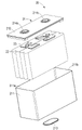
도 5는 본 출원의 일부 실시예에 따른 배터리의 개략적인 분해도를 도시한다;
도 6은 본 출원의 일부 실시예에 따른 배터리의 개략적인 분해도를 도시한다;
도 7은 본 출원의 일부 실시예에 따른 배터리의 단면도이다;
도 8은 도 7에 도시된 배터리의 B 부분의 확대도이다;
도 9는 본 출원의 일부 실시예에 따른 격리 부재의 사시도를 도시한다;
도 10은 본 출원의 일부 실시예에 따른 열관리 부재에 부착되지 않은 격리 부재의 분해도를 도시한다;
도 11은 본 출원의 일부 실시예에 따른 열관리 부재에 부착된 격리 부재의 분해도를 도시한다;
도 12는 본 출원의 일부 실시예에 따른 열관리 부재의 평면도를 도시한다;
도 13은 도 12에 도시된 본 출원의 열관리 부재의 A-A 단면도를 도시한다;
도 14는 도 12에 도시된 본 출원의 열관리 부재의 저면도를 도시한다;
도 15는 본 출원의 일부 실시예에 따른 격리 부재의 사시도를 도시한다;
도 16은 도 15에 도시된 본 출원의 격리 부재의 C 부분의 확대도를 도시한다;
도 17은 도 15에 도시된 본 출원의 격리 부재의 D-D 단면도를 도시한다;
도 18 내지 도 27은 도 17에 도시된 본 출원의 일부 실시예의 격리 부재의 E부분의 확대도를 도시한다;
도 28은 본 출원의 일부 실시예에 따른 격리 부재의 사시도를 도시한다;
도 29는 도 28에 도시된 본 출원의 격리 부재의 F부분의 확대도를 도시한다;
도 30은 도 28에 도시된 본 출원의 격리 부재의 G-G 단면도를 도시한다;
도 31 내지 도 32는 도 30에 도시된 본 출원의 일부 실시예의 격리 부재의 H 부분의 확대도를 도시한다;
도 33 내지 도 35는 본 출원의 일부 실시예에 따른 격리 부재의 돌기부와 감압 기구 사이의 대응 관계의 개략도를 도시한다;
도 36은 본 출원에 따른 배터리 제조 방법의 일부 실시예의 개략적인 흐름도를 도시한다;
도 37은 본 출원에 따른 배터리 제조 장치의 일부 실시예의 개략적인 구조도를 도시한다.BRIEF DESCRIPTION OF THE DRAWINGS The drawings described herein are used to provide a further understanding of the present application, and form a part of the present application, the exemplary embodiments and description of the present application being used to interpret the present application, and inappropriate limitations on the present application. does not constitute In the attached drawing:
1 shows a schematic structural diagram of some embodiments of a vehicle using the battery of the present application;
2 shows a schematic exploded view of a battery cell according to some embodiments of the present application;
3 shows a schematic perspective view of a battery cell according to some embodiments of the present application;
4 shows a schematic perspective view of a battery cell according to some embodiments of the present application;
5 shows a schematic exploded view of a battery according to some embodiments of the present application;
6 shows a schematic exploded view of a battery according to some embodiments of the present application;
7 is a cross-sectional view of a battery according to some embodiments of the present application;
Fig. 8 is an enlarged view of part B of the battery shown in Fig. 7;
9 shows a perspective view of an isolation member in accordance with some embodiments of the present application;
10 shows an exploded view of an isolation member not attached to a thermal management member in accordance with some embodiments of the present application;
11 shows an exploded view of an isolation member attached to a thermal management member in accordance with some embodiments of the present application;
12 shows a top view of a thermal management member in accordance with some embodiments of the present application;
13 shows a cross-sectional view AA of the thermal management member of the present application shown in FIG. 12 ;
Fig. 14 shows a bottom view of the thermal management member of the present application shown in Fig. 12;
15 shows a perspective view of an isolation member in accordance with some embodiments of the present application;
Fig. 16 shows an enlarged view of part C of the isolation member of the present application shown in Fig. 15;
17 shows a DD cross-sectional view of the isolation member of the present application shown in FIG. 15 ;
18-27 show enlarged views of portion E of the isolation member of some embodiments of the present application shown in FIG. 17;
28 shows a perspective view of an isolation member in accordance with some embodiments of the present application;
Fig. 29 shows an enlarged view of part F of the isolation member of the present application shown in Fig. 28;
30 shows a GG cross-sectional view of the isolation member of the present application shown in FIG. 28 ;
31-32 show enlarged views of portion H of the isolation member of some embodiments of the present application shown in FIG. 30;
33-35 show schematic diagrams of a correspondence relationship between a pressure relief mechanism and a protrusion of an isolation member according to some embodiments of the present application;
36 shows a schematic flowchart of some embodiments of a battery manufacturing method according to the present application;
37 shows a schematic structural diagram of some embodiments of an apparatus for manufacturing a battery according to the present application.
본 출원의 목적, 기술 방안 및 이점을 보다 명확하게 하기 위하여, 다음은 본 출원의 여러 실시예를 나타내는 첨부 도면을 참조하여 본 출원의 실시예의 기술 방안에 대하여 명확하고 완전하게 설명하며, 설명된 실시예는 본 출원의 일부 실시예일 뿐 전부는 아님을 이해해야 한다. 본 출원에 기재된 실시예에 기초하여, 창의적인 노력을 들이지 않고 본 분야의 기술자에 의해 획득된 다른 모든 실시예는 본 출원의 보호 범위에 속한다. In order to make the objectives, technical solutions and advantages of the present application more clear, the following clearly and completely describes the technical solutions of the embodiments of the present application with reference to the accompanying drawings showing various embodiments of the present application, and the described implementations It should be understood that the examples are some, but not all, embodiments of the present application. Based on the embodiments described in this application, all other embodiments obtained by those skilled in the art without creative efforts fall within the protection scope of the present application.
달리 정의되지 않는 한, 본 출원에 사용된 모든 기술 및 과학 용어는 본 분야의 기술자가 일반적으로 이해하는 것과 동일한 의미를 갖는다; 본 출원에서 본 출원의 명세서에서 사용한 용어는 단지 특정한 실시예를 설명하기 위해 사용된 것으로, 본 출원을 한정하려는 의도가 아니다; 본 출원의 상세한 설명, 청구 범위 및 첨부 도면의 설명에서 "포괄", "포함", "있음", "구비", "함유", "함" 등의 용어는 개방형 용어이다. 따라서, 예를 들어, 하나 이상의 단계 또는 요소를 "포괄", "포함", "있음"하는 방법 또는 장치는, 하나 이상의 단계 또는 요소를 갖지만, 이 하나 이상의 단계 또는 요소만을 갖는 것으로 제한되지는 않는다. 본 출원의 상세한 설명, 청구 범위 및 첨부 도면에서, "제1", "제2" 등은 단지 서로 다른 대상을 구별하기 위해 사용된 것으로, 특정 순서 또는 주종 관계를 설명하기 위함이 아니다. 또한, "제1", "제2"는 단지 설명의 목적으로 사용되며, 상대적인 중요성을 나타내거나 암시하거나, 또는 지시된 기술 특징의 개수를 암시하는 것으로 이해되어서는 안 된다. 따라서 "제1", "제2"로 정의된 특징은 하나 이상의 특징을 명시적으로 또는 묵시적으로 포함할 수 있다. 본 출원의 설명에서, "복수"는 달리 명시적으로 그리고 구체적으로 정의되지 않는 한 둘 이상을 의미한다. Unless defined otherwise, all technical and scientific terms used in this application have the same meaning as commonly understood by one of ordinary skill in the art; In this application, the terms used in the specification of the present application are used only to describe specific embodiments, and are not intended to limit the present application; In the detailed description of this application, the claims, and the description of the accompanying drawings, terms such as "inclusive", "including", "in", "including", "containing", "comprising" and the like are open-ended terms. Thus, for example, a method or apparatus that "includes", "comprises", "includes" one or more steps or elements has one or more steps or elements, but is not limited to having only the one or more steps or elements. . In the detailed description, claims, and accompanying drawings of the present application, "first", "second", etc. are used only to distinguish different objects, and are not intended to describe a specific order or master-slave relationship. Also, “first” and “second” are used for descriptive purposes only, and should not be construed as indicating or implying a relative importance, or implying a number of indicated technical features. Accordingly, a feature defined as “first” or “second” may explicitly or implicitly include one or more features. In the description of this application, "plurality" means two or more unless explicitly and specifically defined otherwise.
본 출원의 설명에서, 기술 용어 "중심", "가로방향", "길이", “폭”, "상", "하", "전", "후", "좌", "우", "수직", "수평", "상부", “바닥부”, “내”, “외”, "축방향", "반경방향", “원주방향” 등이 지시하는 방위 또는 위치 관계는 첨부 도면에 도시된 방위 또는 위치 관계를 기반으로 본출원을 설명하고 설명을 간략화하기 위함일 뿐, 표시된 장치 또는 구성 요소가 특정의 방향을 갖거나, 특정 방향의 구조 및 작동해야 하는 것이 아니므로, 본 출원의 실시예에 대한 제한으로 해석되어서는 안 된다. In the description of the present application, the technical terms “center”, “transverse direction”, “length”, “width”, “top”, “bottom”, “front”, “after”, “left”, “right”, “ The orientation or positional relationship indicated by “vertical”, “horizontal”, “top”, “bottom”, “inside”, “outside”, “axial”, “radial”, “circumferential”, etc. It is only to explain and simplify the description based on the illustrated orientation or positional relationship, and it is not necessary for the indicated device or component to have a specific orientation, or to have a specific orientation or structure and operation. It should not be construed as a limitation on the examples.
본 출원의 설명에서, 달리 명백하게 규정 및 한정하지 않는 한 "장착", "상호 연결", "연결", “부착”이라는 용어는 넓은 의미로 해석되어야 한다. 예를 들어, 고정 연결, 탈착식 연결, 일체형 연결이 될 수 있으며; 직접 연결 또는 중간 매체를 통한 간접 연결, 두 구성 요소 내부의 연통일 수 있다. 본 분야의 기술자는 특정 상황에 따라 본 출원의 실시예에서 상기 용어들의 구체적인 의미를 이해할 수 있다. In the description of the present application, the terms "mounting", "interconnection", "connection", and "attachment" should be interpreted in a broad sense unless explicitly defined and limited otherwise. For example, it may be a fixed connection, a removable connection, an integral connection; It can be a direct connection or an indirect connection through an intermediate medium, communication between the two components. A person skilled in the art may understand the specific meaning of the terms in the embodiments of the present application according to specific circumstances.
본 명세서에서 언급된 "실시예"는 실시예를 결합하여 설명된 특정 특징, 구조 또는 특성이 본 출원의 적어도 하나의 실시예에 포함될 수 있음을 의미한다. 명세서의 다양한 위치에 있는 이 문구의 출현이 반드시 모두 동일한 실시예를 지칭하는 것은 아니며, 다른 실시예와 상호 배타적인 별도의 또는 대안적인 실시예를 지칭하는 것도 아니다. 본 분야의 기술자는 본 명세서에 설명된 실시예가 다른 실시예와 결합될 수 있다는 것을 명시적으로 그리고 묵시적으로 이해한다. An “embodiment” referred to in this specification means that a particular feature, structure, or characteristic described in combination with the embodiment may be included in at least one embodiment of the present application. The appearances of the phrases in various places in the specification are not necessarily all referring to the same embodiment, nor to separate or alternative embodiments that are mutually exclusive from other embodiments. Those skilled in the art understand explicitly and implicitly that the embodiments described herein may be combined with other embodiments.
전술한 바와 같이, "포괄/포함"이라는 용어가 본 명세서에서 사용될 때, 명시된 특징, 정수, 단계 또는 구성 요소의 존재를 명확하게 나타내기 위해 사용되지만, 하나 이상의 다른 특징, 정수, 단계, 구성 요소 또는 그룹된 특징, 정수, 단계, 구성 요소의 존재 또는 추가를 배제하지 않는다는 것을 강조해야 한다. 본 출원에서 사용된 단수형 "한 개", "하나" 및 "그"는 문맥상 명백하게 달리 지시하지 않는 한 복수형도 포함한다. As noted above, when the term "inclusive/includes" is used herein, it is used to clearly indicate the presence of a specified feature, integer, step, or element, but one or more other features, integers, steps, elements. It should be emphasized that it does not exclude the presence or addition of grouped features, integers, steps, or elements. As used in this application, the singular forms "a," "an," and "the" also include the plural unless the context clearly dictates otherwise.
본 명세서에서 "하나" 및 "한 개"라는 단어는 하나를 의미할 수 있지만, 또한 "적어도 하나" 또는 "하나 이상"의 의미와 일치할 수 있다. 용어 "약"은 일반적으로 언급된 숫자에 10%를 더하거나 뺀 것을 의미하며, 또는 더 구체적으로 5%를 더하거나 뺀 것을 의미한다. 특허 청구 범위에서 사용된 용어 "또는"은 명시적으로 언급되지 않는 한 대체적인 방안만을 지칭하며, 그렇지 않으면 "및/또는"을 의미한다. The words "a" and "an" herein may mean one, but may also be consistent with the meaning of "at least one" or "one or more". The term “about” generally means the stated number plus or minus 10%, or more specifically means plus or minus 5%. As used in the claims, the term “or” refers only to alternative arrangements unless explicitly stated otherwise, otherwise “and/or” is meant.
본 명세서에서 사용된 용어 "및/또는"은 연관된 개체를 설명하기 위한 연관 관계일 뿐이며, 3 유형의 관계가 존재하는 것을 표시할 수 있다. 예를 들어, A 및/또는 B는: A가 단독으로 존재하고, A와 B가 동시에 존재하고, B가 단독으로 존재하는 3가지 경우를 표시할 수 있다. 또한 본 명세서에서 "/" 문자는 일반적으로 전후의 관련 개체가 "또는" 관계임을 나타낸다. The term "and/or" as used herein is merely an association relationship for describing a related entity, and may indicate that three types of relationships exist. For example, A and/or B can represent three cases: A exists alone, A and B exist simultaneously, and B exists alone. Also, in this specification, the "/" character generally indicates that the related entity before and after is a "or" relationship.
이 분야에서 언급되는 배터리는 재충전 여부에 따라 일회용 배터리와 충전식 배터리로 나눌 수 있다. 일회용 배터리(Primary Battery)는 일반적으로 "일회용품" 배터리 및 기본 배터리로 알려져 있다. 왜냐하면 전원이 소진된 후에는 재충전하여 사용할 수 없고 폐기만 할 수 있기 때문이다. 충전식 배터리는 2차 배터리(Secondary Battery) 또는 2급 배터리, 저장 배터리라고 한다. 충전식 배터리의 재료와 공정은 일회용 배터리와 다르며, 충전 후 여러 번 재활용할 수 있고, 충전식 배터리의 출력 전류 부하 용량이 대부분의 일회용 배터리보다 높다는 장점이 있다. 현재 흔히 볼 수 있는 충전식 배터리의 종류는 납축 배터리, 니켈 수소 배터리, 리튬 이온 배터리이다. 리튬 이온 배터리는 경량, 대용량(용량은 같은 무게의 니켈 수소 배터리의 1.5~2배), 메모리 효과가 없는 등의 장점이 있으며, 또한 자기 방전율이 매우 낮아 비교적 고가임에도 불구하고 여전히 널리 사용되고 있다. 리튬 이온 배터리는 순수 전기차와 하이브리드 자동차에도 사용되는데, 이 용도로 사용되는 리튬 이온 배터리는 용량이 상대적으로 작지만 출력과 충전 전류가 더 크며 수명이 더 긴 경우도 있지만 가격이 비싸다. Batteries mentioned in this field can be divided into disposable batteries and rechargeable batteries according to whether they can be recharged or not. Primary Batteries are commonly known as "disposable" batteries and primary batteries. This is because after the power is exhausted, it cannot be used again by recharging it, and can only be disposed of. A rechargeable battery is called a secondary battery, a secondary battery, or a storage battery. The material and process of the rechargeable battery is different from that of the disposable battery, and it has the advantages of being able to recycle many times after charging, and the output current load capacity of the rechargeable battery is higher than that of most disposable batteries. The types of rechargeable batteries that are commonly found today are lead acid batteries, nickel hydride batteries, and lithium ion batteries. Lithium-ion batteries have advantages such as light weight, large capacity (capacity is 1.5 to 2 times that of nickel-metal hydride batteries of the same weight), and no memory effect, and are still widely used despite their relatively low self-discharge rate. Lithium-ion batteries are also used in pure electric and hybrid vehicles, where lithium-ion batteries have a relatively small capacity, but have a higher output and charge current, and in some cases a longer lifespan, but are expensive.
본 출원의 실시예에서 설명된 배터리는 충전식 배터리를 의미한다. 이하, 주로 리튬 이온 배터리를 예로 들어 본 출원에 개시된 실시예를 설명한다. 임의의 다른 적합한 유형의 충전식 배터리에도 적용 가능한 것을 이해해야 하다. 본 출원의 실시예에서 언급된 배터리는 더 높은 전압 및 용량을 제공하기 위해 하나 이상의 배터리 셀을 포함하는 단일 물리적 모듈을 의미한다. 예를 들어, 본 출원에서 언급된 배터리에는 배터리 모듈 또는 배터리 팩 등이 포함될 수 있다. 배터리 셀은 양극편, 음극편, 전해액 및 분리막을 포함하며, 배터리 모듈과 배터리 팩을 구성하는 기본 구성 유닛이다. 배터리 셀은 일반적으로 포장 방법에 따라 원통형 배터리 셀, 각형 배터리 셀 및 소프트 팩 배터리 셀의 세 가지 유형으로 나뉜다. The battery described in the embodiments of the present application means a rechargeable battery. Hereinafter, embodiments disclosed in the present application will be mainly described by taking a lithium ion battery as an example. It should be understood that it is also applicable to any other suitable type of rechargeable battery. A battery referred to in the embodiments of the present application means a single physical module including one or more battery cells to provide higher voltage and capacity. For example, the battery referred to in the present application may include a battery module or a battery pack. A battery cell includes a positive electrode, a negative electrode, an electrolyte, and a separator, and is a basic structural unit constituting a battery module and a battery pack. Battery cells are generally divided into three types according to the packaging method: cylindrical battery cells, prismatic battery cells, and soft pack battery cells.
리튬 이온 배터리 셀은 주로 양극편과 음극편 사이의 리튬 이온 이동에 의존하여 작동한다. 리튬 이온 배터리 셀은 삽입된 리튬 화합물을 전극 재료로 사용한다. 현재 리튬 이온 배터리에 사용되는 주요 양극 재료는 리튬 코발트 산화물(LiCoO2), 망간산 리튬(LiMn2O4), 니켈산 리튬(LiNiO2) 및 리튬 인산철(LiFePO4)이다. 양극편과 음극편 사이에 분리막을 설치하여 3층의 재료로 이루어진 박막 구조를 형성한다. 박막 구조는 일반적으로 권선 또는 적층하여 원하는 형상의 전극 조립체로 만들어진다. 예를 들어, 원통형 배터리 셀의 3층 재료의 박막 구조는 원통형 전극 조립체로 감겨 있는 반면, 각형 배터리 셀의 박막 구조는 감겨지거나 혹은 적층되어 대략 직육면체 형태의 전극 조립체를 형성한다. Lithium-ion battery cells operate primarily by relying on the movement of lithium ions between the positive and negative poles. A lithium ion battery cell uses an intercalated lithium compound as an electrode material. Currently, the main cathode materials used in lithium-ion batteries are lithium cobalt oxide (LiCoO2), lithium manganate (LiMn2O4), lithium nickelate (LiNiO2), and lithium iron phosphate (LiFePO4). A separator is provided between the anode and cathode to form a thin film structure made of three layers of material. The thin film structure is generally made into an electrode assembly having a desired shape by winding or laminating. For example, the thin film structure of a three-layer material of a cylindrical battery cell is wound into a cylindrical electrode assembly, whereas the thin film structure of a prismatic battery cell is wound or stacked to form an electrode assembly in the form of a substantially rectangular parallelepiped.
복수의 배터리 셀은 전극 단자를 통해 직렬 및/또는 병렬로 함께 연결될 수 있다. 다양한 응용에 사용될 수 있다. 전기 자동차와 같은 일부 고전력 응용 분야에서 배터리 적용에는 배터리 셀, 배터리 모듈 및 배터리 팩의 세 가지 수준이 있다. 배터리 모듈은 외부 충격, 열, 진동 등으로부터 배터리 셀을 보호하기 위해 일정 수의 배터리 셀을 전기적으로 함께 연결하고 프레임에 넣어 형성한다. 배터리 팩은 전기차에 탑재되는 배터리 시스템의 최종 상태이다. 현재 대부분의 배터리 팩은 하나 이상의 배터리 모듈에 배터리 관리 시스템(BMS), 열관리 부재 등과 같은 다양한 제어 및 보호 시스템을 내장하여 제작된다. 배터리 분야의 기술이 발전함에 따라, 배터리 모듈의 단계를 생략할 수 있게 되었다. 즉, 배터리 셀로부터 배터리 팩을 직접 형성할 수 있다. 이러한 개선을 통해 배터리 시스템은 중량 에너지 밀도 및 체적 에너지 밀도를 개선함과 동시에 부품 수를 크게 줄일 수 있다. 본 출원에서 언급된 배터리는 배터리 모듈 또는 배터리 팩을 포함한다. A plurality of battery cells may be connected together in series and/or parallel through electrode terminals. It can be used for a variety of applications. In some high power applications, such as electric vehicles, there are three levels of battery application: battery cells, battery modules and battery packs. A battery module is formed by electrically connecting a certain number of battery cells together and putting them in a frame to protect the battery cells from external shock, heat, vibration, and the like. A battery pack is the final state of a battery system installed in an electric vehicle. Currently, most battery packs are manufactured by embedding various control and protection systems such as a battery management system (BMS), a thermal management member, etc. in one or more battery modules. As the technology in the battery field develops, it is possible to omit the step of the battery module. That is, the battery pack can be directly formed from the battery cells. These improvements allow battery systems to significantly reduce component count while improving gravimetric and volumetric energy density. Batteries referred to in this application include battery modules or battery packs.
배터리 셀의 경우, 주요 안전 위험은 충전 및 방전 과정에서 발생하며, 불필요한 손실을 효과적으로 방지하기 위해 일반적으로 배터리 셀은 최소한 세 가지 보호 조치가 설계된다. 구체적으로, 보호 조치에는 최소한 스위칭 소자, 적절한 분리막 재료 및 감압 기구가 포함된다. 스위칭 소자는 배터리 셀의 온도 또는 저항이 일정 임계값에 도달하면 배터리의 충전 또는 방전을 멈출 수 있는 소자를 말한다. 분리막은 양극편과 음극편을 분리하는 데 사용되며, 온도가 일정 값까지 상승하면 그에 부착된 마이크로 규모(또는 나노 규모)의 미세 기공을 자동으로 용해하여 리튬 이온이 분리막을 통과하지 못하게 하여 배터리의 내부 반응을 멈추게 한다. For battery cells, the main safety hazard arises during the charging and discharging process, and in order to effectively prevent unnecessary losses, battery cells are usually designed with at least three protective measures. Specifically, protective measures include, at a minimum, a switching element, a suitable separator material and a pressure reducing mechanism. The switching device refers to a device capable of stopping charging or discharging of a battery when a temperature or resistance of a battery cell reaches a predetermined threshold. The separator is used to separate the positive and negative parts, and when the temperature rises to a certain value, it automatically dissolves the micro-scale (or nano-scale) micropores attached thereto to prevent lithium ions from passing through the separator, thereby protecting the battery. Stop internal reactions.
감압 기구는 배터리 셀의 내부 압력 또는 내부 온도가 미리 결정된 임계값에 도달하면 작동하여 내부 압력 및/또는 내부 물질을 방출할 수 있는 요소 또는 부품을 의미한다. 감압 기구는 구체적으로 방폭 밸브, 공기 밸브, 감압 밸브 또는 안전 밸브의 형태를 취할 수 있으며 또한 구체적으로 압력 감지 또는 온도 감지의 요소 또는 구조를 채택할 수 있다. 즉, 배터리 셀의 내부 압력이나 온도가 소정의 임계값에 도달하면, 감압 기구가 작용을 하거나 감압 기구에 구비된 박약 구조가 파손되어 내부 압력을 방출하기 위한 개구 또는 통로가 형성된다. 본 출원에서 언급된 임계값은 압력 임계값 또는 온도 임계값일 수 있으며, 임계값의 설계는 다양한 설계 요구 사항에 따라 변한다. 예를 들어 위험하거나 폭주할 위험이 있는 것으로 간주되는 배터리 셀의 내부 압력 또는 내부 온도 값을 기반으로 임계값을 설계 또는 결정할 수 있다. 또한, 임계값은 예를 들어 배터리 셀의 양극편, 음극편, 전해액 및 분리막 중 하나 이상에 사용되는 재료에 따라 달라질 수 있다. A decompression mechanism means an element or component capable of activating when the internal pressure or internal temperature of a battery cell reaches a predetermined threshold to release internal pressure and/or internal substances. The pressure reducing mechanism may specifically take the form of an explosion-proof valve, an air valve, a pressure reducing valve or a safety valve, and may also specifically adopt an element or structure of pressure sensing or temperature sensing. That is, when the internal pressure or temperature of the battery cell reaches a predetermined threshold value, the pressure reducing mechanism acts or the thin structure provided in the pressure reduction mechanism is broken to form an opening or passage for releasing the internal pressure. The threshold referred to in this application may be a pressure threshold or a temperature threshold, and the design of the threshold varies according to various design requirements. For example, a threshold may be designed or determined based on the internal pressure or internal temperature value of a battery cell that is considered hazardous or at risk of runaway. Further, the threshold value may vary depending on the material used for one or more of, for example, a positive electrode piece, a negative electrode piece, an electrolyte, and a separator of a battery cell.
본 출원에서 언급된 "작동"이라는 용어는 감압 기구가 동작하거나 활성화되어 배터리 셀의 내부 압력 또는 물질을 방출하는 것을 의미한다. 감압 기구가 동작한다는 것은 감압 기구의 적어도 일부가 파열, 찢어짐, 파쇄 또는 개방 등이 포함되지만 이에 국한되지 않는다. 감압 기구가 작동되면, 배터리 셀 내부의 고온 고압 물질이 작동 부위로부터 외부로 배출된다. 이러한 방식으로 제어된 압력/온도 조건에서 배터리 셀의 압력 또는 배출물의 방출이 발생될 수 있으므로 더 심각한 사고를 피할 수 있다. 본 출원에서 언급된 배터리 셀로부터의 배출물은: 전해액, 용해 또는 분열된 양극편 및 음극편, 분리막의 파편, 반응에 의해 생성된 고온 고압 가스 및/또는 화염 등을 포함하지만 이에 국한되지는 않는다. 일반적으로 고온 고압의 배출물은 배터리 셀의 감압 기구 방향으로 배출되고, 또한 보다 구체적으로 감압 기구가 작동되는 영역의 방향으로 배출되며, 배출물의 위력과 파괴력이 크며, 이 방향에 설치된 커버 등과 같은 하나 이상의 구조물을 뚫을 수도 있다. As used herein, the term “actuation” means that the pressure reducing mechanism is operated or activated to release the internal pressure or substance of the battery cell. Operation of the pressure reducing mechanism includes, but is not limited to, at least a portion of the pressure reduction mechanism is ruptured, torn, crushed, or opened. When the decompression mechanism is operated, the high-temperature and high-pressure material inside the battery cell is discharged from the operation part to the outside. In this way, under controlled pressure/temperature conditions, release of pressure or emissions from the battery cells can occur, thus avoiding more serious accidents. Emissions from battery cells referred to in this application include, but are not limited to: electrolyte, dissolved or fractured positive and negative poles, fragments of separators, high-temperature and high-pressure gases and/or flames produced by the reaction, and the like. Generally, the high-temperature and high-pressure discharge is discharged in the direction of the pressure reducing mechanism of the battery cell, and more specifically, discharged in the direction of the area where the pressure reduction mechanism is operated, and the power and destructive force of the discharge are large, and at least one such as a cover installed in this direction. It can also penetrate structures.
전통적인 감압 기구는 일반적으로 배터리 셀의 커버판에 설치된다. 일부 개선된 기술 방아에서 감압 기구는 배터리 셀의 다른 면 또는 하우징 구조의 다른 방향에 배치될 수도 있다. 그러나, 갑압 기구가 배치되는 방법 또는 위치에 관계없이 배터리에 배치된 적절한 부착 부재를 사용하여 접착제(본딩제 또는 접합제라고도 함)를 사용하여 배터리 셀을 부착 부재에 부착하거나 조립해야 하며, 그 중에서, 부착 부재는 구체적으로 배터리의 열관리 부재 및 지지 부재와 같은 부착 부재를 포함할 수 있으며, 접착제는 예를 들어, 열전도성 실리카겔, 에폭시 수지 접착제, 폴리우레탄 접착제 등일 수 있다. Traditional decompression mechanisms are usually installed on the cover plate of the battery cell. In some advanced technologies, the pressure reducing mechanism may be disposed on the other side of the battery cell or on the other side of the housing structure. However, regardless of how or where the depressurization mechanism is disposed, the battery cells must be attached or assembled to the attachment member using an adhesive (also called a bonding agent or bonding agent) using an appropriate attachment member disposed on the battery, among which , the attachment member may specifically include an attachment member such as a thermal management member and a support member of a battery, and the adhesive may be, for example, a thermally conductive silica gel, an epoxy resin adhesive, a polyurethane adhesive, and the like.
본 출원에서 언급된 지지 부재는 일반적으로 배터리 셀에 대한 지지 작용을 제공하거나 배터리 셀의 중력 효과에 저항하기 위한 부재로 이해될 수 있으며, 이는 일반적으로 배터리 셀을 지지하거나 고정하기 위해 배터리 셀 하우징의 바닥 벽 또는 바닥부에 부착될 수 있다. 열관리 부재는 배터리 셀의 온도를 조절하기 위해 유체를 수용하는 부품으로, 여기서 유체는 액체 또는 기체일 수 있으며, 온도 조절은 배터리 셀을 가열하거나 냉각하는 것을 의미한다. 일반적으로 배터리 셀을 냉각하는 데 사용되는 열관리 부재는 냉각 부재, 냉각 시스템 또는 냉각판 등으로도 불릴 수도 있다. 그것은 냉각 액체 또는 냉각 가스와 같은 냉각 매체를 수용하며, 냉각 매체는 더 나은 온도 조절을 위해 순환되도록 설계될 수 있다. 냉각 매체로서는 물, 물과 에틸렌 글리콜의 혼합액 또는 공기 등을 사용할 수 있다. 부착 부재는 일반적으로 배터리에서 접착제를 통해 배터리 셀과 접착되는 부분을 말하며, 부착 부재는 열관리 부재 또는 지지 부재에 의해 제공되거나 구성될 수 있으며, 그 외에, 부착 부재는 배터리의 다른 적절한 부재에 의해 제공될 수도 있다. A support member referred to in this application may generally be understood as a member for providing a supporting action for a battery cell or for resisting the gravitational effect of a battery cell, which is generally a part of a battery cell housing to support or fix the battery cell. It can be attached to a floor wall or floor. The thermal management member is a component for receiving a fluid to control the temperature of the battery cell, wherein the fluid may be a liquid or a gas, and temperature control means heating or cooling the battery cell. A thermal management member generally used to cool a battery cell may also be referred to as a cooling member, a cooling system, or a cooling plate. It contains a cooling medium, such as a cooling liquid or cooling gas, which may be designed to be circulated for better temperature control. As the cooling medium, water, a mixture of water and ethylene glycol, or air can be used. The attachment member generally refers to a portion of a battery that is adhered to a battery cell through an adhesive, the attachment member may be provided or configured by a thermal management member or a support member, otherwise the attachment member may be provided by another suitable member of the battery it might be
배터리의 어느 부분이 부착 부재로 사용되는지에 관계없이 접착제를 사용하여 배터리 셀을 배터리에 조립하는 방법은 일반적으로 접착제를 부착 부재와 배터리 셀이 서로 부착되는 접합면에 도포하거나 코팅하고, 그 후, 접착제가 경화되어 발생하는 접착력과 응집력을 이용하여 배터리 셀을 부착 부재의 해당 접합면에 표면 접합 방식으로 접합함으로써 배터리 셀을 부착 부재에 조립하는 목적을 실현한다. 이 설계와 가공 방법은 구현이 쉽고 공정이 간단하며 비용이 저렴하며 견고하고 안정적인 부착이 가능하기 때문에 널리 사용된다. Regardless of which part of the battery is used as an attachment member, the method of assembling a battery cell to a battery using an adhesive is generally performed by applying or coating the adhesive to the bonding surface where the attachment member and the battery cell are attached to each other, and then, The purpose of assembling the battery cell to the attachment member is realized by bonding the battery cell to the corresponding bonding surface of the attachment member in a surface bonding method using the adhesive force and cohesive force generated by curing the adhesive. This design and machining method is widely used because of its ease of implementation, simple process, low cost, and robust and reliable attachment.
그러나, 본 출원의 발명자들은 많은 연구와 실험을 수행한 결과, 접착제를 사용하여 배터리 셀을 배터리의 부착 부재에 부착하는 설계가 의외로 배터리 셀의 안전한 사용을 위한 신뢰할 수 있는 보증을 제공하는 감압 기구의 설계에 악영향을 미칠 수 있다는 것을 발견하였다. However, as a result of many studies and experiments conducted by the inventors of the present application, the design of attaching the battery cell to the attachment member of the battery using an adhesive is unexpectedly a decompression mechanism that provides a reliable guarantee for the safe use of the battery cell. It was found that the design could be adversely affected.
구체적으로, 한편으로는 접착제를 도포할 때, 예를 들어, 의도하지 않은 특정 영역에 접착제를 너무 많이 도포하거나 접착제가 도포되는 접착 표면의 경사로 인해 일부 접착제가 감압 기구의 작동과 관련된 영역으로 유입될 수 있다. 이 경우 유입되는 접착제를 청소하지 않으면 경화된 접착제가 감압 기구의 작동에 악영향을 미칠 수 있으며, 심지어 감압 기구가 작동될 때 형성되는 배출물이 유출되는 통로 또는 개구를 차단하거나 부분적으로 차단하여 배출물의 배출에 영향을 미칠 수도 있다. Specifically, on the one hand, when applying the adhesive, for example, applying too much adhesive to a specific unintended area or the inclination of the adhesive surface to which the adhesive is applied may cause some adhesive to enter the area associated with the operation of the pressure-sensitive mechanism. can In this case, if the incoming adhesive is not cleaned, the cured adhesive may adversely affect the operation of the pressure-sensitive mechanism, and even block or partially block the passage or opening through which the discharge formed when the pressure-sensitive mechanism is operated, resulting in discharge of the discharge. may affect
다른 한편으로, 배터리 셀 내부의 압력이나 온도가 소정의 임계값에 도달했을 때 배터리 셀 내부의 감압 기구가 작동되면 배터리 셀 내부의 고온 고압의 물질이 배출물로서 작동된 부위로부터 외부로 배출된다. 이때 고온 고압의 배출물은 배출 과정에서 자체의 파괴력 및/또는 고온으로 인해 배출물 경로 이외의 근처의 접착 표면에 도포된 접착제가 용융되어 감압 기구의 작동과 관련된 영역으로 유입되어, 예를 들어, 감압 기구가 작동되는 위치 또는 감압 기구의 작동에 의해 형성된 배출물이 유출되는 통로 또는 개구부에 유입되어, 배출물의 배출에 악영향을 미친다. On the other hand, if the pressure reducing mechanism inside the battery cell is operated when the pressure or temperature inside the battery cell reaches a predetermined threshold value, the high-temperature and high-pressure material inside the battery cell is discharged as discharge from the operated portion to the outside. At this time, the high-temperature and high-pressure discharge flows into an area related to the operation of the pressure-reducing mechanism by melting the adhesive applied to the adhesive surface in the vicinity other than the discharge path due to its own destructive force and/or high temperature in the discharge process, for example, the pressure-reducing mechanism The discharge formed by the operation of the position or the pressure reducing mechanism is introduced into the outlet passage or opening, adversely affecting the discharge of the discharge.
감압 기구가 필요할 때 배터리 셀 내부의 고온 고압의 배출물을 방출하는 설계된 기능을 수행할 수 있도록 하려면, 어떤 방식으로든 열전도성 실리콘과 같은 접착제의 도포가 감압 기구의 작동 또는 배출물을 유출하도록 감압 기구에 형성된 개구부 또는 통로의 영역에 영향을 미치는 것을 방지해야 한다. 그러나 이를 위해 배터리 셀을 배터리에 조립하기 위한 부착 부재에 접착제의 사용을 포기하거나 또는 접착제를 도포해야 하는 배터리 셀 또는 부착 부재의 접착 표면 주위에 차단 구조를 추가하면, 배터리의 제조 난이도와 생산 비용을 크게 증가시킨다. 따라서 배터리 셀에 설치된 감압 기구가 설계 기능을 발휘하여 배터리의 사용 안전을 보장하고, 동시에, 배터리의 제조 난이도 및 제조 원가를 가능한 한 낮게 유지하는 것은 연구자 및 당업자에게 어려운 기술적 문제이다.In order for the pressure relief mechanism to perform its designed function of releasing the high-temperature, high-pressure discharge inside the battery cell when needed, the application of an adhesive, such as thermally conductive silicone, in any way forms the action of the pressure-relief mechanism or on the pressure-relief mechanism to bleed the discharge. It should be prevented from affecting the area of the opening or passageway. However, for this purpose, if the use of adhesive is abandoned on the attachment member for assembling the battery cell to the battery, or a barrier structure is added around the adhesive surface of the battery cell or attachment member to which the adhesive needs to be applied, the manufacturing difficulty and production cost of the battery are reduced. greatly increase Therefore, it is a difficult technical problem for researchers and those skilled in the art to ensure that the pressure reducing mechanism installed in the battery cell has a design function to ensure the safety of use of the battery and, at the same time, to keep the manufacturing difficulty and manufacturing cost of the battery as low as possible.
전술한 문제점 및 종래 기술의 배터리의 다른 잠재적인 문제점을 해결하거나 적어도 부분적으로 해결하기 위해, 본 출원의 발명자는 배터리를 제안하고, 그 설계는 하기에 상세히 설명될 것이다. 본 출원의 실시예에서 설명되는 배터리는 배터리를 사용하는 다양한 장치, 예를 들어, 휴대폰, 휴대용 기기, 노트북, 배터리 자동차, 전기 자동차, 선박, 우주선, 전기 장난감 및 전동 공구 등에 적용될 수 있음을 이해할 수 있다. 예를 들어 우주선은 비행기, 로켓, 우주왕복선, 우주선 등을 포함하며, 전기 장난감은 고정식 또는 이동식 전기장난감을 포함하며, 예를 들어, 게임 콘솔, 전기 자동차 장난감, 전기 선박 장난감 및 전기 항공기 장난감 등이 있다. 전동 공구는 금속 절삭 전동 공구, 연삭 전동 공구, 조립 전동 공구 및 철도 전동 공구 등을 포함하며, 예를 들어, 전기 드릴, 전기 그라인더, 전기 렌치, 전기 스크루 드라이버, 전기 해머, 전기 충격 드릴, 콘크리트 진동기 및 전기 대패가 있다. In order to solve, or at least partially solve, the above problems and other potential problems of batteries of the prior art, the inventors of the present application propose a battery, the design of which will be described in detail below. It can be understood that the battery described in the embodiment of the present application may be applied to various devices using the battery, for example, a mobile phone, a portable device, a notebook computer, a battery car, an electric vehicle, a ship, a spaceship, an electric toy, and a power tool. have. For example, spacecraft includes airplanes, rockets, space shuttles, spacecraft, etc., and electric toys include stationary or mobile electric toys, such as game consoles, electric vehicle toys, electric ship toys, and electric aircraft toys. have. Power tools include metal cutting power tools, grinding power tools, assembly power tools and railway power tools, for example, electric drills, electric grinders, electric wrenches, electric screwdrivers, electric hammers, electric shock drills, concrete vibrators, etc. and electric planers.
본 출원의 실시예에서 설명되는 배터리는 전술한 장치에 한정되지 않고, 배터리를 사용하는 모든 장치에 적용될 수 있으나, 간결함을 위해 이하의 실시예에서는 전기 자동차를 예로 들어 설명한다. The battery described in the embodiment of the present application is not limited to the above-described device and may be applied to any device using the battery, but for the sake of brevity, the following embodiment will take an electric vehicle as an example.
예를 들어, 도 1은 본 출원의 실시예에 따른 차량(1)의 간단한 개략도를 도시한다. 차량(1)은 연료 차량, 휘발유 차량 또는 신에너지 차량이 될 수 있으며, 신에너지 자동차는 순수 전기 자동차, 하이브리드 자동차 또는 장거리 자동차 등이 될 수 있다. 도 1에 도시된 바와 같이, 배터리(10)는 차량(1)의 내부에 설치될 수 있으며, 예를 들어, 배터리(10)는 차량(1)의 바닥부 또는 차량의 전방 또는 후방에 설치될 수 있다. 배터리(10)는 차량(1)의 전원 공급에 사용될 수 있고, 예를 들어 배터리(10)는 차량(1)의 작동 전원으로서 사용될 수 있다. 그리고 차량(1)은 제어기(30)와 모터(40)를 더 포함할 수 있다. 제어기(30)는 모터(40)의 전원 공급을 위해 배터리(10)를 제어하는데 사용된다. 예를 들어, 차량(1)의 시동, 탐색 및 구동 시의 작동 전력 요구 사항에 사용된다. 본 출원의 다른 실시예에서, 배터리(10)는 차량(1)의 작동 전원으로 사용될 수 있을 뿐만 아니라 또한 차량(1)의 구동 전원으로 사용되어, 연료 또는 천연 가스를 교체하거나 부분적으로 교체하여 차량(1)에 구동 동력을 제공할 수 있다. 이하에서 언급되는 배터리(10)는 또한 복수의 배터리 셀(20)을 포함하는 배터리 팩으로 이해될 수 있다. For example, FIG. 1 shows a simplified schematic diagram of a
도 2-4에 도시된 바와 같이, 배터리 셀(20)은 케이스(21), 전극 조립체(22) 및 전해액을 포함한다. 전극 조립체(22)는 배터리 셀(20)의 케이스(21)에 수용되며, 전극 조립체(22)는 양극편, 음극편 및 분리막을 포함한다. 분리막의 재질은 폴리프로필렌(polypropylene, PP) 또는 폴리에틸렌(polyethylene, PE) 등일 수 있다. 전극 조립체(22)는 권선 구조 또는 적층 구조일 수 있다. 케이스(21)는 하우징(211) 및 커버판(212)을 포함할 수 있다. 하우징(211)은 복수의 벽에 의해 형성된 수용 캐비티(211a) 및 개구부(211b)를 포함한다. 커버판(212)은 개구부(211b)에 배치되어 수용 캐비티(211a)를 폐쇄한다. 수용 캐비티(211a)에는 전극 조립체(22) 외에 전해액도 수용된다. 전극 조립체(22)의 양극편과 음극편에는 일반적으로 탭이 설치되고, 탭은 일반적으로 양극탭과 음극탭을 포함한다.2-4, the
구체적으로, 양극편은 양극 집전체 및 양극 활물질층을 포함하고, 양극 활물질층은 양극 집전체의 표면에 코팅되며, 양극 활물질층이 코팅되지 않은 양극 집전체는 양극 활물질층이 코팅된 양극 집전체로부터 돌출되며, 양극 활물질층이 코팅되지 않은 양극 집전체는 양극 탭으로 사용되며, 양극 집전체의 재료는 알루미늄일 수 있고 양극 활물질은 리튬 코발트 산화물, 리튬 인산철, 삼원 리튬 또는 망간산 리튬 등일 수 있다; 음극편은 음극 집전체 및 음극 활물질층을 포함하고, 음극 활물질층은 음극 집전체의 표면에 코팅되며, 음극 활물질층이 코팅되지 않은 음극 집전체는 음극 활물질층이 코팅된 음극 집전체로부터 돌출되며, 음극 활물질층이 코팅되지 않은 음극 집전체는 음극 탭으로 사용된다. 음극 집전체의 재료는 구리일 수 있고, 음극 활물질은 탄소 또는 실리콘 등일 수 있다. 큰 전류가 퓨징 없이 흐르도록 하기 위해 양극 탭의 개수는 복수이고 함께 적층되며, 음극 탭의 개수는 복수이고 함께 적층된다. 탭은 연결 부재(23)를 통해 배터리 셀(20) 외부의 양극 단자(214a) 및 음극 단자(214b)와 연결된다. 본 출원의 설명에서 양극 단자(214a)와 음극 단자(214b)를 합쳐서 전극 단자(214)라고 칭한다. 각형 배터리 셀의 경우, 도 2 내지 도 4에 도시된 바와 같이, 전극 단자(214)는 일반적으로 커버판(212) 부분에 설치될 수 있다. Specifically, the positive electrode piece includes a positive electrode current collector and a positive electrode active material layer, the positive electrode active material layer is coated on the surface of the positive electrode current collector, and the positive electrode current collector on which the positive electrode active material layer is not coated is a positive electrode current collector coated with a positive electrode active material layer A positive electrode current collector that protrudes from and is not coated with a positive electrode active material layer is used as a positive electrode tab, and the material of the positive electrode current collector may be aluminum, and the positive electrode active material may be lithium cobalt oxide, lithium iron phosphate, ternary lithium or lithium manganate. have; The negative electrode piece includes a negative electrode current collector and a negative electrode active material layer, the negative electrode active material layer is coated on the surface of the negative electrode current collector, and the negative electrode current collector without the negative electrode active material layer protrudes from the negative electrode current collector on which the negative electrode active material layer is coated. , the negative electrode current collector on which the negative electrode active material layer is not coated is used as the negative electrode tab. The material of the negative electrode current collector may be copper, and the negative electrode active material may be carbon or silicon. In order to allow a large current to flow without fusing, the number of positive electrode tabs is plural and stacked together, and the number of negative electrode tabs is plural and stacked together. The tab is connected to the
도 5-6은 본 출원의 일부 실시예에 따른 배터리(10)의 분해도를 도시한다. 도 5-6에 도시된 바와 같이, 배터리(10)는 복수의 배터리 셀(20)을 포장하기 위한 박스 본체(11)를 포함한다. 박스 본체(11)는 배터리 셀의 충전 또는 방전에 영향을 미치는 액체 또는 기타 이물질을 방지할 수 있으며, 그 중에서 복수의 배터리 셀(20)은 버스 부재(12)을 통해 서로 전기적으로 연결되며, 버스 부재(12)를 통해 복수의 배터리 셀(20)을 직렬 및 병렬로 연결한 후에 배터리(10)는 더 높은 전압을 제공할 수 있다. 박스 본체(11)는 커버 본체(111) 및 박스 쉘(112)을 포함할 수 있다. 여기서, 커버 본체(111)와 박스 쉘(112)은 서로 밀봉되어 결합되어 복수의 배터리 셀(20)을 수용하는 전기 캐비티(11a)를 공동으로 둘러싸 형성할 수 있으며, 물론 둘은 밀봉 없이 서로 결합될 수도 있다. 일부 실시예에서, 열관리 부재(13)는 복수의 배터리 셀(20)을 수용하기 위한 박스 본체(11)의 일부를 형성할 수 있다. 예를 들어, 열관리 부재(13)는 박스 본체(11)의 박스 쉘(112)의 측면부(112b)를 구성하거나 측면부(112b)의 일부를 구성할 수 있고, 또는, 도 6에 도시된 바와 같이, 열관리 부재(13)는 박스 본체(11)의 박스 쉘(112)의 바닥부(112a)를 구성하거나 바닥부(112a)의 일부를 구성할 수 있다. 열관리 부재(13)를 사용하여 박스 쉘(112)의 일부를 구성하는 이러한 설계는 배터리(10)의 구조를 보다 콤팩트하게 만들고, 공간의 효과적인 활용을 개선하고, 에너지 밀도를 개선하는 데 도움이 된다. 5-6 show exploded views of the
일부 대안적인 실시예에서, 배터리(10)는 또한 도 6 및 도 7에 도시된 바와 같이 보호 부재(115)를 포함할 수 있다. 본 출원에서 보호 부재(115)는 열관리 부재(13) 및 배터리 셀(20)을 보호하기 위해 배터리 셀(20)로부터 떨어진 열관리 부재(13) 일측에 배치되는 부재를 말한다. 이러한 실시예에서, 수집 캐비티(11b)는 보호 부재(115)와 열관리 부재(13) 사이에 배치될 수 있다. In some alternative embodiments, the
도 7 내지 도 8에 도시된 바와 같이, 배터리(10)의 적어도 하나의 배터리 셀(20)은 감압 기구(213)를 포함한다. 일부 실시예에서, 배터리(10)의 각 배터리 셀(20)에는 감압 기구(213)가 설치되거나, 감압 기구(213)는 또한 배터리(10) 내에서의 위치 또는 다른 배터리 셀(20)의 특성으로 인해 열 폭주가 발생하기 쉬운 배터리 셀(20)의 부분에 설치될 수 있다. 감압 기구(213)는 배터리 셀(20)의 내부 압력 또는 온도가 미리 결정된 임계값에 도달할 때 배터리 셀(20)의 내부 압력을 완화하도록 작동될 수 있다. 7 to 8 , at least one
배터리(10)는 또한 접착제에 의해 배터리 셀(20)에 부착되도록 구성된 부착 부재를 포함하며, 부착 부재는 예를 들어 배터리(10) 내의 열관리 부재(13), 지지 부재 등일 수 있다. 열전도성 실리콘과 같은 접착제가 부착 부재와 감압 기구(213) 사이에 도포되어 감압 기구(213)가 작동되거나 전술한 바와 같은 설계 기능을 발휘하는 것을 방해하거나 영향을 미치는 것을 방지하기 위해, 즉 배터리 셀(20)의 내부 압력 또는 온도가 상대적으로 높을 때 작동되어 배터리 셀(20)의 내부 압력을 완화하기 위한 통로 또는 개구부를 형성하기 위해, 배터리(10)에는 또한 격리 부재(14)가 설치될 수 있고, 격리 부재(14)는 부착 부재와 감압 기구(213) 사이에 접착제가 도포되는 것을 방지할 수 있다. 이하에서는 주로 부착 부재가 열관리 부재(13)인 실시예 및 그와 관련된 격리 부재(14)의 설계를 중심으로 설명할 것이며, 부착 부재가 지지 부재인 경우에는, 실질적으로 동일하거나 유사한 격리 부재(14)의 구성 또는 배치가 사용될 수 있다. The
도 8에는 격리 부재(14)가 개략적으로 도시되어 있으며, 격리 부재(14)는 접착제가 작동 영역에 들어가는 것을 방지하기 위해 적어도 감압 기구(213)의 작동 영역을 둘러싸고 있다. 이러한 방식으로, 접착제가 임의의 방향으로부터 작동 영역으로 유입되어 감압 기구의 작동 동작을 저해하거나 악영향을 미치는 것을 회피할 수 있다. 8 schematically shows an
본 출원의 다양한 실시예에서 사용되는 격리 부재(14)는 배터리 셀(20)을 부착 부재에 조립하는데 사용되는 전술한 접착제가 부착 부재와 감압 기구(213) 사이의 공간으로부터 격리될 수 있도록 다양한 구성이 가능하다. 즉 도포된 접착제가 일단 접착제가 유입되면 감압 기구(213)가 설계된 감압 기능을 수행하는데 영향을 미칠 수 있는 공간으로부터 격리되게 할 수 있다. 아래의 일부 바람직한 실시예의 설명에서 알 수 있는 바와 같이, 격리 부재(14)는 감압 기구(213)의 일부 영역을 둘러싸도록 설계될 수 있으며, 이 일부 영역은 감압 기구(213)이 작동될 때 배터리 셀(20)의 내부 압력을 해제하기 위한 방출 통로(작동 영역 또는 방출 영역으로 지칭될 수 있음)를 형성하여 배출물을 유출할 수 있으며, 또는 감압 기구(213)에 대응하는 열관리 부재(13)와 같은 부착 부재 상의 영역에 부착되어 감압 기구(213)의 작동이 허용되는 부착 부재에 의해 제공되는 공간(예를 들어, 아래에서 설명되는 회피 구조(134))을 둘러쌀 수도 있다. The
일부 실시예에서, 격리 부재(14)는 접착제를 도포하기 전에 감압 기구(213)에 대응하는 열관리 부재(13)와 같은 부착 부재의 영역에 부착될 수 있다. 배터리의 부품이 접착제에 의해 배터리 셀과 접착되어 있는 한, 그들은 부착 부재 또는 부착 부재의 일부로 간주될 수 있으며, 이러한 부품은 모두 격리 부재(14)을 사용할 수 있으며, 즉 접착제를 코팅하기 전에 격리 부재(14)를 그에 부착할 수 있다. 이러한 방식으로 접착제가 도포될 때, 격리 부재(14)는 접착제가 감압 기구에 대응하는 특히 작동되어 배터리 셀의 내부 압력을 방출하는 방출 통로를 형성하여 배출물을 유출하는 감압 기구에 대응하는 부착 부재 상의 영역에 유입되는 것을 방지하여, 감압 기구(213)가 작동되고 그 설계 기능을 정상적으로 실현하는 것을 보장할 수 있다. 또한, 격리 부재(14)의 사용은 접착제의 도포 속도 및 정확도를 가속화할 수 있고, 접착제를 감압 기구(213)의 작동과 관련된 영역에 도포하는 것에 대해 걱정할 필요가 없으며, 생산 시간 비용을 절약할 수 있다.In some embodiments, the
도 9는 본 출원의 일부 실시예에 따른 격리 부재(14)의 사시도를 도시하고, 도 10은 도 9에 도시된 격리 부재(14)와 열관리 부재(13)가 함께 조립되지 않은 상태의 부착 부재의 분해도를 도시하고, 도 11은 도 9에 도시된 격리 부재(14)와 열관리 부재(13)가 함께 부착될 때의 사시도를 도시한다. 도 9 내지 도 11에 도시된 실시예에 따르면, 격리 부재(14)는 접착제를 도포하기 전에 열관리 부재(13)와 같은 부착 부재에 부착될 수 있고, 또한 격리 부재(14)의 특별한 구조적 특징이 감압 기구(213) 또는 부착 부재에 설치된 회피 구조(134)에 적어도 대응하도록 하고, 여기서 회피 구조(134)는 감압 기구(213)가 작동할 수 있도록 하는 공간을 제공할 수 있다. 관련된 회피 구조(134)의 구체적인 구조 및 특징은 아래에서 상세히 설명될 것이다. 9 shows a perspective view of an
도 9 내지 도 11에 도시된 바와 같이, 본 출원의 일부 실시예에 따르면, 격리 부재(14)는 본체(141) 및 복수의 돌기부(142)를 포함할 수 있다. 그 중에서, 본체(141)는 열관리 부재(13)와 같은 부착 부재에 부착되거나 조립되도록 구성된다. 돌기부(142)는 본체(141)의 표면에서 외측으로 돌출되며, 또한 돌기부(142)는 본체(141)가 부착 부재에 부착되었을 때 감압 기구(213) 또는 감압 기구(213)의 방출 영역 또는 후술하는 일부 실시예의 회피 구조(134) 또는 회피 캐비티(134a)와 돌출 방향으로 정렬되도록 구성된다. 도 10 내지 도 11에 도시된 예에서, 돌기부(142)가 회피 구조(134)와 정렬되도록 배치되지만, 도 8을 참조하면 회피 구조(134) 자체의 설치는 감압 기구(213)에 대응하거나, 또는 2개가 나란히 정렬되는 것을 이해하는 것은 어렵지 않으므로, 돌기부(142)는 또한 감압 기구(213)와 정렬되거나 그 작동 영역(또는 방출 영역)과 정렬되는 것으로 간주될 수 있다. 또한, 다른 도시되지 않은 실시예에서, 예를 들어 배터리(10)에 회피 구조(134)가 설치되지 않는 예시에서, 돌기부(142)는 또한 감압 기구(213)와 직접 정렬되거나 그 작동 영역 또는 방출 영역과 정렬되도록 배치될 수 있다. 9 to 11 , according to some embodiments of the present application, the
본 명세서에서 설명되는 격리 부재(14)에 포함된 본체(141) 및 돌기부(142)는 격리 부재(14)가 상호 독립적인 부분을 포함해야 함을 나타내기 위한 것이 아니며, 또한 아래의 바람직한 실시예들에 대한 설명에 따르면, 본체(141)와 돌기부(142)가 모두 일체로 형성되는 구조가 다양한 측면에서 보다 유리할 수 있다. The
본 출원에서 본체(141)는 지지 부재 또는 열관리 부재(13)와 같은 부착 부재에 용이하게 부착되도록 설계된 격리 부재(14)의 일부로 이해될 수 있으며, 돌기부(142)는 본체(141)의 표면에서 돌출되도록 설계되며, 돌기부(142)의 외주 크기는 감압 기구(213)의 외주보다 크거나 같거나 또는 적어도 감압 기구(213)의 방출 면적보다 크거나 같다. 이러한 방식으로, 접착제를 도포할 때 한편으로는 접착제 도포 장치는 미리 정해진 경로에 따라 접착 작업을 수행하도록 안내될 수 있고, 다른 한편으로는 감압 기구(213)가 위치하는 위치에 접착제가 도포되지 않도록 하여, 접착제가 적절한 위치에 효율적이고 정확하게 도포될 수 있다. In the present application, the
도 9 내지 도 11에 도시된 실시예에서, 격리 부재(14)는 가늘고 긴 시트형 본체(141)를 갖도록 설계되고, 각각의 본체(141)는 돌출된 1열의 돌기부(142)를 갖도록 설계되었지만, 본 출원에서의 본체(141) 및 돌기부(142)는 감압 기구(213)의 형상 및 구조 및 기타 요인에 따라 다양한 형상을 가질 수 있다. 배터리의 중량 에너지 밀도 또는 부피 에너지 밀도를 고려하면, 본체(141)는 일반적으로 상대적으로 얇은 두께를 가지므로, 본체(141)는 일반적으로 다양한 형상의 필름 또는 시트 형태일 수 있다. 통상적으로, 격리 부재(14) 또는 본체(141)의 벽 두께는 0.01mm 내지 0.05mm일 수 있다. 돌기부(142)의 형상은, 예를 들어, 도면에 도시된 바와 같이 장원형 또는 원형, 타원형, 사각형 등일 수 있다. 또한, 단일의 본체(141)는 단일의 돌기부(142), 복수 열의 돌기부(142) 또는 다른 방식으로 배열된 복수의 돌기부(142)를 가지도록 설계될 수 있으며, 본체(141)의 표면에 있는 돌축부(142)의 배치 및 상대적인 위치는 배터리 셀(20)의 감압 기구(213)의 설정 위치에 적응될 수 있기만 하면 된다. 9-11, the
바람직한 일부 실시예에 따르면, 단일의 격리 부재(14)는 하나의 본체(141)와 본체(141)의 표면에서 돌출된 복수의 돌기부(142)를 포함하도록 설계될 수 있으며, 본체(141)는 배터리의 부착 부재에 일체로 부착되며, 또한 이러한 부착의 경우, 복수의 돌기부(142)는 배터리(10)에 포함된 복수의 배터리 셀(20)의 감압 기구(213)(또는 감압 기구(213)의 방출 영역)와 각각 일대일 대응되게 정렬되므로 각 돌기부(142)는 정렬된 감압 기구(213)를 각각 둘러쌀 수 있다(또는 적어도 감압 기구(213)의 방출 영역을 둘러쌀 수 있음). 이에 의해, 격리 부재(14)를 배터리의 부착 부재에 조립하는 과정이 더 간단하고, 동시에 복수의 돌기부(142)를 이용하여 도포되거나 도포될 접착제를 상대적으로 독립적인 방식으로 배터리에 포함된 복수의 배터리 셀(20)의 감압 기구(213) 또는 그의 방출 영역으로부터 격리할 수 있다. 또한, 이것은 작업자가 접착제를 도포할 때 더 높은 효율로 접착제 도포를 적절하게 완료하는 데 도움이 될 수 있으므로 작업자가 접착제를 조심스럽게 도포하는 작업을 수행할 필요가 없으므로 배터리(10)의 조립 비용 및 생산 비용이 감소된다. According to some preferred embodiments, the
상기 방안에 기초하여, 단일의 격리 부재(14)가 복수의 돌기부(142)를 갖도록 설계될 수 있기 때문에, 이러한 설계는 하나의 배터리(10)에 복수의 배터리 셀(20)이 수용되고 또한 복수의 배터리 셀(20) 각각에 감압 기구(213)가 설치되는 전형적인 배터리 유형에 특히 유리하다. 이는 단일의 격리 부재(14)가 제자리에 조립될 때 복수의 돌기부(142)가 복수의 배터리 셀(20)의 감압 기구(213)에 대해 접착제를 격리하는 역할을 할 수 있기 때문이다. Based on the above scheme, since a
복수의 배터리 셀(20)을 포함하는 배터리(10)에서, 배터리 셀(20)은 일반적으로 배터리(10)의 부착 부재에 일렬로 부착될 수 있다. 이 경우, 전술한 바와 같이 하나의 본체(141)와 본체(141)의 표면에서 돌출된 복수의 돌기부(142)를 포함하는 격리 부재(14)를 사용할 수 있으며, 격리 부재(14)는 일체로 형성된 일체형 시트일 수 있으며, 또한 격리 부재(14)의 본체(141)가 배터리(10)의 부착 부재에 부착되면, 그 위의 복수의 돌기부(142)는 배터리에 포함된 복수의 배터리 셀(20)의 감압 기구(213)와 일대일 대응되도록 정렬될 수 있다. 대안적으로, 복수의 배터리 셀(20)을 위한 복수의 격리 부재(14)는 또한 일체로 형성될 수 있으며, 여기서 일렬로 배치된 복수의 격리 부재(14)의 위치는 각각 복수의 배터리 셀(20)의 감압 기구(213)의 위치에 대응한다. 이와 같이, 복수의 배터리 셀(20)을 배터리(10)에 조립하는 조립 공정을 간단하게 할 수 있고, 조립 효율을 높일 수 있다. In a
본 출원의 일부 실시예에 따르면, 앞서 언급된 도 8 및 10 및 도 12 내지 도 13에 도시된 바와 같이, 열관리 부재(13)와 같은 부착 부재에는 회피 구조(134)가 설치될 수 있으며, 회피 구조(134)와 감압 기구(213) 사이에는 회피 캐비티(134a)가 형성되어, 감압 기구(213)가 작동할 수 있는 공간을 제공하고, 이들 실시예에서, 격리 부재(14) 및 그 안의 돌기부(142)의 배치는 회피 구조(134) 또는 회피 캐비티(134a)의 배치에 대응하거나 정렬될 것이다. According to some embodiments of the present application, as shown in FIGS. 8 and 10 and FIGS. 12 to 13 mentioned above, an
구체적으로, 회피 캐비티(134a)은 예를 들어 회피 구조(134)와 감압 기구(213)에 의해 함께 둘러싸 형성되는 폐쇄 캐비티일 수 있다. 이 방안에서, 배터리 셀(20)로부터의 배출물의 배출을 위해, 감압 기구(213)의 작동에 의해 회피공(134a)의 입구 일측 표면이 개방될 수 있고, 입구 일측 표면과 반대되는 출구 일측 표면은 고온 고압의 배출물로 인해 부분적으로 파괴되고 개방되어 배출물을 위한 방출 통로를 형성할 수 있다. 다른 실시예에 따르면, 회피 캐비티(134a)는, 예를 들어, 회피 구조(134)와 감압 기구(213)가 함께 둘러싸 형성되는 밀봉되지 않은 캐비티일 수 있고, 이 밀봉되지 않은 캐비티의 출구 일측 표면은 원래 배출물이 유출될 수 있는 통로를 가질 수 있다. 도 8의 회피 캐비티(134a)에서 화살표로 표시된 바와 같이, 배출물은 일반적으로 부채꼴 방향으로 바깥쪽으로 배출될 것이다. Specifically, the avoiding
일부 실시예에 따르면, 도 12 내지 도 14에 도시된 바와 같이, 열관리 부재(13)는 회피 캐비티(134)의 바닥부에 있는 회피 바닥벽(134b) 및 회피 캐비티(134a)를 둘러싼 회피 측벽(134c)을 더 포함한다. 여기서 말하는 회피 바닥벽(134b)은 감압 기구(213)와 대향되는 회피 캐비티(134a)의 벽을 말하며, 회피 측벽(134c)은 회피 바닥벽(134b)과 인접하고 또한 일정한 각도를 형성하여 회피 캐비티(134a)를 둘러싼 벽이다. 그 중에서 회피 측벽(134c)과 회피 바닥벽(134b)이 이루는 끼인각은 105°~175°인 것이 바람직하다. 열관리 부재(13)에는 또한 유체를 수용하기 위한 유로(133)가 설치될 수 있고, 유체는 배터리 셀(20)을 냉각할 수 있는 냉각 매체일 수 있다. According to some embodiments, as shown in FIGS. 12-14 , the
대응되게, 이러한 실시예에서, 격리 부재(14)의 복수의 돌기부(142)는 도 10 내지 도 11에 도시된 바와 같이 배치될 수 있으며, 여기서 각 돌기부(142)는 정렬된 회피 캐비티(134a)을 각각 둘러쌀 수 있다. 즉, 돌기부(142)는 기본적으로 대응되는 회피 캐비티(134a)의 회피 측벽(134c)의 상부 가장자리 또는 그 외부에서 덮인다. 즉, 차단 부재(14)의 돌기부(142)는 대응되는 회피 캐비티(134a)의 상부 가장자리에서 실질적으로 덮여 있어서, 도포되거나 도포될 접착제가 회피 구조(134) 또는 회피 캐비티(134a)으로부터 격리된다. Correspondingly, in this embodiment, the plurality of
전술한 바람직한 실시예에 따른 열관리 부재(13) 및 격리 부재(14)는 배터리의 조립 효율을 향상시키는데 매우 유리하다. 여기서, 격리 부재(14)를 배터리의 부착 부재에 조립하는 과정이 비교적 간단함과 동시에 복수의 돌기부(142)를 이용하여 배터리에 포함된 복수의 배터리 셀(20)의 감압 기구(213)에 대응하는 회피 캐비티(134a)로부터 도포되거나 도포된 접착제를 비교적 독립적으로 분리할 수 있다. 따라서, 도포된 접착제가 배터리 셀(20)의 감압 기구(213)가 설계된 기능을 수행하는데 영향을 미치는 것을 방지할 수 있어 배터리의 안전한 사용을 보장할 수 있다. 또한, 이는 또한 작업자가 접착제를 도포할 때 더 높은 효율로 접착제 도포를 적절하게 완료하는 데 도움이 될 수 있다. The
예를 들어, 도 10 내지 도 11에 도시된 실시예에서, 단일의 긴 시트형 본체(141)가 열관리 부재(13)에 조립되고 제자리에 있을 때, 본체(141) 상의 8개의 돌기부(142)는 정렬된 8개의 회피 구조(134) 또는 회피 캐비티(134a)에 각각 덮여서 접착제가 회피 캐비티(134a)로 유입되지 않도록 한다. 즉, 단일의 격리 부재(14)를 한번 조립하여 8개 이상의 배터리 셀(20)의 감압 기구(213)의 격리 동작을 실현할 수 있다. For example, in the embodiment shown in FIGS. 10-11 , when the single elongated sheet-
본 출원은 배터리 셀(20)에서 감압 기구(213)의 배치 방향 및 위치를 제한하지 않는다는 것을 이해해야 하며, 사실 감압 기구(213)가 배터리 셀(20)의 하부, 상부 또는 측부 등에 배치되더라도, 본 출원에서 제안하는 격리 부재(14)의 해당 설계가 적절하게 적용될 수 있고, 감압 기구(213)가 설계 기능을 실현하는 것을 보장하여 필요할 때 배터리 셀 내의 고온 고압 배출물을 방출하여 배터리의 안전한 사용을 보장하는 유익한 작용을 한다. It should be understood that the present application does not limit the arrangement direction and position of the
일부 실시예에서, 도 12 내지 도 14에 도시된 바와 같이, 열관리 부재(13)는 다음과 같은 구체적인 구성을 갖도록 설계될 수 있다. 여기서, 열관리 부재(13)는 제1 열전도판(131) 및 제2 열전도판(132)을 포함할 수 있고, 제2 열전도판(132)은 유로(133)에 대응되는 홈 구조로 형성되며, 제1 열전도판(131)에는 회피 구조(134)가 형성되고, 제1 열전도판(131)과 제2 열전도판(132)을 함께 조립함으로써, 예를 들어 제1 열전도판(131)과 제2 열전도판(132)을 용접(예를 들어, 브레이징)하여 조립할 수 있으므로, 상기 실시예에서 설명한 바와 같은 열관리 부재(13)이 형성될 수 있다. 물론, 이러한 제1 열전도판(131)과 제2 열전도판(132)을 조립하여 열관리 부재(13)을 형성하는 방법은 하나의 예시일 뿐이며, 전술한 열관리 부재(13)은 다른 적절한 방법으로도 형성될 수 있다. In some embodiments, as shown in FIGS. 12 to 14 , the
여기서, 열관리 부재(13)에 설치된 유로(133)는 적어도 부분적으로 회피 캐비티(134)를 둘러싸도록 배치될 수 있다. 즉 회피 측벽(134c)은 유로(133)와 회피 캐비티(134a)를 분리시키며, 회피 측벽(134c)에는 예를 들어 고온 고압 배출물에 의해 쉽게 파손되는 박약 구조가 설치될 수 있다. 본 출원에서 언급된 박약 구조는 두께 감소된 부분, 노치(예를 들어, 도 10 및 12에 도시된 바와 같은 십자형 노치(134d)), 깨지기 쉬운 재료로 만든 취약부, 또는 융점이 낮은 재료로 만든 취약부 등을 포함할 수 있지만 이에 국한되지 않는다. Here, the
이러한 방식을 통해, 배터리 셀(20)로부터의 배출물이 회피 캐비티(134a)로 유입될 때, 회피 측벽(134c)의 박약 구조를 파괴하여 유로(133) 내의 냉각 액체와 같은 냉각 매체가 회피 캐비티(134a)로 유출되고 냉각 액체가 배터리 셀(20)의 고온 고압 배출물을 접촉하여 많은 양의 열을 흡수하고 기화되어 배터리 셀(20)로부터의 고온 고압 배출물의 온도 및 압력을 단시간에 현저히 감소시켜 배터리(10) 중 열 폭주가 발생하지 않은 다른 배터리 셀(20)의 부품을 보호한다. 또한, 격리 부재(14)의 복수의 돌기부(142)는 기본적으로 대응하는 회피 캐비티(134a)의 회피 측벽(134c)의 상단 가장자리 또는 그 너머로 덮여 있으므로, 이러한 설계는 배출물이 회피 측벽(134c)의 박약 구조를 파괴하고 동시에 냉각 매체를 도입하게 할 수 있어, 격리 부재(14) 및 그 돌기부(142)는 여전히 외부에 위치하는 열전도성 실리카 겔과 같은 접착제에 대해 일정한 차단 효과를 수행하여 배터리의 안전성을 향상시킨다. In this way, when the discharge from the
도 9-14와 관련하여 위의 내용은 주로 격리 부재(14)를 다른 부품과 분리하여, 예를 들어, 부착 부재 또는 감압 기구(213) 사이의 상대적인 위치 관계에 기초하여 격리 부재(14)의 전체적인 구조 또는 구성에 대해 설명한다. 이에 기초하여, 격리 부재(14)는 전술한 기능을 달성하기 위해 다양한 가능한 구성으로 설계될 수 있다. 즉, 배터리 셀(20)을 부착 부재에 조립할 때 사용하는 접착제를 부착 부재와 감압 기구(213) 사이의 공간으로부터 격리하고, 또는 도포된 접착제를 일단 접착제가 유입되면 감압 기구(213)가 감압의 설계 기능을 수행하는데 영향을 줄 수 있는 공간으로부터 격리할 수 있다. 격리 부재(14)의 보다 구체적인 구조는 도 15 내지 도 32를 참조하여 이하에서 주로 상세히 설명한다. 9-14, the above mainly describes the separation of the
도 15는 본 출원의 일부 실시예에 따른 격리 부재(14)의 사시도를 도시하고, 도 16은 도 15에 도시된 격리 부재(14)의 C 부분의 확대도를 도시하고, 도 17은 도 15에 도시된 격리 부재(14)의 D-D의 단면도를 도시하고, 도 18은 도 17에 도시된 격리 부재(14)의 단면의 E 부분의 확대도를 도시한다. 도 15 내지 도 18에 도시된 실시예에 따르면, 격리 부재(14)는 돌기부(142)의 특수 설계를 이용하여 열전도성 실리카 겔과 같은 접착제를 보다 효과적으로 차단하여 접착제를 부착 부재와 감압 기구(213) 사이의 공간으로부터 격리시킬 수 있으므로, 감압 기구(213)가 작동되고 또한 일반적으로 설계된 기능을 실현할 수 있음을 보장한다. 15 shows a perspective view of an
도 15 내지 도 18에 도시된 바와 같이, 본 출원의 일부 실시예에 따르면, 격리 부재(14) 상에 설치된 돌기부(142)는 제1 돌기부(1421) 및 제2 돌기부(1422)를 포함하며, 여기서 제1 돌기부(1421)와 제2 돌기부(1422)는 본체(141)의 표면에서 동일한 방향으로 돌출된다. 제자리에 조립될 때, 격리 부재(14)는 배터리 셀(20)과 부착 부재 사이에 설치된다. 따라서, 구체적으로 격리 부재(14)의 본체(141)를 부착 부재에 부착하는 경우, 제1 돌기부(1421) 및 제2 돌기부(1422)는 본체(141)의 표면에서 부착 부재로부터 멀어지는 방향, 즉 배터리 셀(20)을 향하여 돌출되도록 배치된다. 15 to 18, according to some embodiments of the present application, the
제1 돌기부(1421)는 감압 기구(213)의 위치에 대응한다. 구체적으로, 전술한 바와 같이 제1 돌기부(1421)는 본체(141)가 부착 부재에 부착되는 경우 감압 기구(213) 또는 감압 기구(213)의 작동 영역(또는 방출 영역), 또는 전술한 실시예의 회피 구조(134) 또는 회피 캐비티(134a)와 돌출 방향에서 정렬된다. 제1돌기부(1421)의 돌출 높이는 접착제를 도포할 때와 같이 감압 기구(213)와 부착 부재 사이의 공간으로 접착제가 유입되는 것을 방지하고, 유입된 접착제가 감압 기구(213)의 정상적인 작동을 방해하는 것을 방지하는 이점이 있다. The
제2 돌기부(1422)는 제1 돌기부(1421)와 분리 설치된다. 도 16에 도시된 바와 같이, 제2 돌기부(1422)는 제1 돌기부(1421)의 둘레에 설치되고, 구체적으로 제2 돌기부(1422)는 환형 구조이며, 제1 돌기부(1421)를 둘러싼 외주에 설치된다. 제2 돌기부(1422)의 돌출 높이는 또한 제1 돌기부(1421) 주위에서 접착제가 감압 기구(213)와 부착 부재 사이의 공간으로 유입되는 것을 차단하는 데 유리하다. 또한, 제2돌기부(1422)가 제1돌기부(1421)의 둘레에 설치되기 때문에 둘이 구조상 협력하여 접착제에 대한 다중 차단 역할을 하므로 접착제를 보다 효과적이고 확실하게 차단하여 접착제가 부착 부재와 감압 기구(213) 사이로 유입되어 배터리 셀(20)의 내부 압력 또는 온도가 임계값에 도달할 때 감압 기구(213)의 정상적인 작동을 방해하는 것을 방지하고, 또한 접착제가 유입되어 방출 통로를 차단하여 배터리 셀(20)이 방출하는 배출물의 배출을 차단하는 것을 방지함으로써 배터리(10)의 안전 성능을 더욱 향상시킨다. The
일부 실시예에서, 도 16 및 18을 참조하면, 제1 돌기부(1421)와 제2 돌기부(1422) 사이에 홈(143)이 형성된다. 홈(143)은 접착제의 적어도 일부를 수용하여, 도포되거나 도포될 접착제가 부착 부재와 감압 기구(213) 사이에 도포되는 것을 방지할 수 있다. 홈(143)은 구체적으로 제2 돌기부(1422)를 넘은 접착제의 일부, 배터리 셀(20)을 부착 부재에 부착하는 과정에서 접착제가 실수로 홈(143)에 떨어진 접착제, 및 다른 이유로 홈(143)으로 유입된 접착제 등을 수용할 수 있다. In some embodiments, referring to FIGS. 16 and 18 , a
제1 돌기부(1421)와 제2 돌기부(1422) 사이의 홈(143)은 접착제의 적어도 일부를 수용할 수 있으며, 이는 접착제를 위한 다른 장벽을 추가하는 것과 동일하다. 제2 돌기부(1422)가 그 주변 접착제가 제1 돌기부(1421)로 흐르는 것을 차단하는 경우, 제2 돌기부(1422)가 접착제를 차단하는 기능이 실패하면 홈(143)은 제2 돌기부(1422)에서 넘친 일정량의 접착제를 저장할 수 있고, 이에 의해, 접착제가 감압 기구(213)와 부착 부재 사이의 공간으로 더 흘러 들어가는 것이 방지된다. The
격리 부재(14)가 더 나은 접착제 차단 효과를 달성하도록 하기 위해, 제1 돌기부(1421), 제2 돌기부(1422) 또는 홈(143)의 구조가 그에 따라 설계될 수 있다. In order for the
일부 실시예에서, 도 18을 참조하면, 제2 돌기부(1422)는 제1 측벽(1422a), 제2 측벽(1422b), 및 제1 측벽(1422a)과 제2 측벽(1422b)을 연결하는 연결벽(1422c)을 포함한다. 본 출원의 실시예에서, 제1 측벽(1422a)은 본체(141)와 연결되고, 제2 측벽(1422b)은 본체(141)와 연결되며, 제1 측벽(1422a)과 제2 측벽(1422b)은 서로 대향되게 설치된다. 그 중에서 제1 측벽(1422a)은 제1 돌기부(1421)에 가깝고, 제1 측벽(1422a)은 제2 돌기부(1422)와 홈(143)이 공유하는 벽이다. In some embodiments, referring to FIG. 18 , the
일부 실시예에서, 도 18에 도시된 바와 같이, 제1 측벽(1422a)과 제2 측벽(1422b)은 배터리 셀(20)이 부착 부재에 부착되는 경우 부착 부재가 배터리 셀(20)을 향하는 방향과 평행하며, 즉 제1 측벽(1422a)과 제2 측벽(1422b)은 제2 돌기부(1422)의 돌출 방향과 평행하다. 연결벽(1422c)은 제2 돌기부(1422)의 돌출 방향과 수직이다. 이러한 구조의 격리 부재(14)는 접착제 차단 효과가 우수할 뿐만 아니라 가공에 필요한 금형이 비교적 간단하고 가공이 용이하며 비용이 저렴하다. In some embodiments, as shown in FIG. 18 , the
일부 실시예에서, 도 19를 참조하면, 제1 측벽(1422a) 및 제2 측벽(1422b) 중 적어도 하나는 제1 돌출부(1401)를 포함하고, 제1 돌출부(1401)는 제1 방향(X)을 따라 돌출되며, 여기서 제1 방향(X)과 제2 돌기부(1422)는 돌출 방향이 수직이다. In some embodiments, referring to FIG. 19 , at least one of the
여기서 제1 방향(X)은 도 17에 도시된 D-D 단면에 위치하며, 제2 돌기부(1422)의 돌출 방향과 수직인 방향이다. 따라서, 본 출원의 실시예에서 제1 방향(X)은 도 19에서 화살표로 표시된 방향과 같이 제2 돌기부(1422)의 돌출 방향에 수직인 것으로 이해되어야 한다. Here, the first direction X is located in the cross section D-D shown in FIG. 17 , and is a direction perpendicular to the protrusion direction of the
예시적으로, 제1 측벽(1422a)에 설치된 제1 돌출부(1401)를 예로 들면, 제2 돌기부(1422)의 실제 돌출 방향은 부착 부재가 배터리 셀(20)을 향하는 방향이고, 이해와 설명의 편의를 위해 제2 돌기부(1422)의 지면을 따라 위로 향하는 방향을 돌출 방향으로 예로 들면, 제1 방향(X)은 제2 돌기부(1422)의 돌출 방향에 수직인 방향, 예를 들어 지면을 따른 우측 방향이다. 따라서, 제1 돌출부(1401)는 화살표가 가리키는 제1 방향(X)으로 돌출될 수 있다. Illustratively, taking the
본 출원의 실시예에서, 홈(143)과 제2 돌기(1422)는 제1 측벽(1422a)을 공유하므로, 제1 측벽(1422a)에 제1 돌출부(1401)가 설치되고 또한 제2 측벽(1422b)에 가까운 방향으로 돌출된다. 이러한 방식으로 제2 돌기부(1422)가 접착제 차단 요건을 충족하는 동안, 제1 돌출부(1401)는 또한 홈(143)의 수용 체적을 증가시켜 더 많은 접착제를 수용할 수 있고, 접착제가 부착 부재와 감압 기구(213) 사이의 공간으로 들어가는 것을 방지할 수 있다. In the embodiment of the present application, since the
제1 측벽(1422a)에 설치된 제1 돌출부(1401)는 도 19에 도시된 화살표 방향의 반대 방향으로도 돌출될 수 있거나, 제1 돌출부(1401)가 제2 측벽(1422b)에도 설치될 수 있고, 제2 측벽(1422b) 상의 제1 돌출부(1401)는 제2 돌기부(1422)의 돌출 방향과 수직인 방향으로 돌출될 수 있으며, 예를 들어, 제1 측벽(1422a)에 가깝거나 멀어지는 방향으로 돌출될 수 있으나, 본 출원의 이 실시예는 이것을 제한하지 않는다. The
실제 적용에서, 제1 돌출부(1401)는 요구 사항에 따라 제1 측벽(1422a) 및/또는 제2 측벽(1422b)에 설치되어, 접착제를 효과적으로 차단하고 홈(143)의 수용 체적을 증가시키고, 제2 돌기부(1422)가 차지하는 공간을 줄이고 제조 과정에서 격리 부재(14)의 금형 인발 등의 효과 중 하나 이상을 용이하게 한다. In practical application, the
본 출원의 실시예에서, 제1 돌출부(1401)는 제1 측벽(1422a) 또는 제2 측벽(1422b)의 적어도 일부에 의해 형성된다. In the embodiment of the present application, the
일부 실시예에서, 도 20을 참조하면, 제1 측벽(1422a) 및 제2 측벽(1422b) 중 적어도 하나는 배터리 셀(20)을 향하는 부착 부재의 방향에 대해 경사지게 설치된다. In some embodiments, referring to FIG. 20 , at least one of the
예시적으로, 제1 측벽(1422a) 및 제2 측벽(1422b) 모두 경사지게 설치되는 것을 예로 들면, 도 20에 도시된 바와 같이, 연결벽(1422c)에 연결된 제1 측벽(1422a)의 일단은 제2 측벽(1422b)이 위치하는 일측으로 경사지고, 연결벽(1422c)에 연결된 제2 측벽(1422b)의 일단은 제1 측벽(1422a)이 위치하는 일측으로 경사진다. 그 중에서 제1 측벽(1422a)의 경사진 설치는 더 많은 접착제를 수용하도록 홈(143)의 수용 체적을 증가시킬 수 있고, 이에 의해 접착제가 감압 기구(213)와 부착 부재 사이에 유입되는 것을 효과적으로 방지할 수 있다. 제2 측벽(1422b)의 경사진 설치는 제2 돌기부(1422) 주변에 접착제의 코팅 면적을 증가시켜 접합의 신뢰성을 보장할 수 있다. 또한, 제1 측벽(1422a) 및/또는 제2 측벽(1422b)의 경사진 설치는 제조 과정에서 격리 부재(14)의 금형 인발을 용이하게 할 수 있다. Illustratively, for example, if both the
다른 실시예에서, 제1 측벽(1422a) 및/또는 제2 측벽(1422b)의 경사진 설치 방향은 또한 다른 형태를 가질 수 있음을 이해해야 한다. 예를 들어 연결벽(1422c)에 연결된 제1 측벽(1422a)의 일단은 제1 돌기부(1421)가 위치하는 일측으로 경사지고, 및/또는 연결벽(1422c)에 연결된 제2 측벽(1422b)의 일단은 제1 측벽(1422a)으로부터 멀어지는 일측으로 경사지며, 이는 본 출원의 이 실시예에서 제한되지 않는다. It should be understood that in other embodiments, the inclined installation direction of the
실제 적용에서, 제1 측벽(1422a) 및/또는 제2 측벽(1422b)은 동시에 경사질 수 있으며, 제1 돌출부(1401)는 제1 측벽(1422a) 및/또는 제2 측벽(1422b)에 설치되며, 이는 본 출원의 실시예에서 제한되지 않는다. In practical application, the
참고로, 제1 측벽(1422a) 또는 제2 측벽(1422b)이 배터리 셀(20)을 향하는 부착 부재의 방향에 대해 경사지게 설치된 것인지 여부를 판단할 때, 제1 측벽(1422a) 또는 제2 측벽(1422b)이 위치하는 메인 평면과 배터리 셀(20)을 향하는 부착 부재의 방향 사이의 공간적 관계에 따라 결정될 수 있다. 제1 측벽(1422a)의 메인 평면을 예로 들면, 이는 제1 측벽(1422a)이 위치하는 평면일 수 있고, 또는 제1 측벽(1422a)의 대부분이 위치하는 평면일 수 있고, 또는 제1 측벽(1422a)의 평평한 부분이 위치하는 평면 등일 수 있다. For reference, when determining whether the
일부 실시예에서, 도 21을 참조하면, 연결벽(1422c)은 제2 돌출부(1402)를 포함하고, 제2 돌출부(1402)는 배터리 셀(20)을 향하는 부착 부재의 방향을 따라 돌출되게 설치되거나, 부착 부재를 향하는 배터리 셀(20)의 방향을 따라 돌출되게 설치된다. 제2 돌기부(1422)의 돌출 방향은 배터리 셀(20)을 향하는 부착 부재의 방향이므로, 제2 돌출부(1402)는 제2 돌기부(1422)의 돌출 방향을 따라 돌출되게 설치되거나, 제2 돌기부(1422)의 돌출 방향과 반대 방향으로 돌출되게 설치되는 것으로도 이해될 수 있다. In some embodiments, referring to FIG. 21 , the
예시적으로, 도 21에 도시된 바와 같이, 제2 돌출부(1402)는 부착 부재를 향하는 배터리 셀(20)의 방향을 따라 돌출된다. 제2 돌출부(1402)의 설치는 연결벽(1422c)의 표면을 요철로 만들어 접착제를 수용할 수 있는 공간을 형성한다. 이와 같이 접착제의 높이가 제2돌기부(1422)의 높이를 초과하여 제1돌기부(1421)를 향해 흐르는 경향이 있는 경우, 접착제는 먼저 연결벽(1422c) 표면의 수용공간에 남게 되는데, 이는 접착제가 제1 돌기부(1421) 방향으로 계속 흐르는 것을 방지하기 위해 다른 장벽을 추가하는 것과 동일하다. 제2 돌기부(1422)의 폭이 충분하고 연결벽(1422c)의 표면의 곡률이 더 작을수록 연결벽(1422c)이 저장할 수 있는 접착제가 더 많아진다. For example, as shown in FIG. 21 , the
본 출원의 실시예에서, 제2 돌출부(1402)는 연결벽(1422c)의 적어도 일부에 의해 형성된다. In the embodiment of the present application, the
제2 돌출부(1402)는 배터리 셀(20)의 방향을 향해 돌출될 수 있음을 이해해야 하며, 이는 본 출원의 실시예에서 제한되지 않는다. 제2 돌출부(1402)의 구조를 합리적으로 설계함으로써, 제2 돌기부(1422)가 차지하는 공간을 줄일 수 있고, 홈(143)의 수용 체적을 늘릴 수 있다. It should be understood that the
또한, 실제 적용에서 연결벽(1422c)에 제2 돌출부(1402)가 설치될 수 있음과 동시에, 제1 측벽(1422a) 및 제2 측벽(1422b) 중 적어도 하나에는 제1 돌출부(1401)가 설치되고, 및/또는 제1 측벽(1422a) 및 제2 측벽(1422b) 중 적어도 하나는 경사지게 설치되며, 이는 본 출원의 실시예에서 제한되지 않는다. In addition, in practical application, the
일부 실시예에서, 도 22를 참조하면, 제2 돌기부(1422)는 캐비티(1404)를 포함한다. 제1 측벽(1422a), 제2 측벽(1422b) 및 연결벽(1422c) 중 적어도 하나에는 개구(1405)가 설치된다. 개구(1405)는 캐비티(1404)와 연통되어 접착제의 적어도 일부가 개구(1405)를 통해 캐비티(1404)로 들어간다. In some embodiments, referring to FIG. 22 , the
본 출원의 실시예에서, 제2 돌기부(1422)의 적어도 하나의 벽에 개구(1405)를 설치함으로써, 제2 돌기부(1422) 주위에 위치된 접착제는 개구(1405)를 통해 캐비티(1404)에 들어갈 수 있으므로, 제2 돌기부(1422)가 차지하는 공간을 충분히 활용함은 물론, 제2 돌기부(1422) 주변의 접착제를 감소시켜 접착제가 부착 부재와 감압 기구(213) 사이의 공간으로 유입되는 것을 방지할 수 있다. In an embodiment of the present application, by providing an
개구부(1405)가 제2 돌기부(1422)의 적어도 하나의 벽에 설치되는 방식에서, 제2 돌기부(1422)의 형상은 전술한 도 18 내지 도 21 또는 하기 도면에 도시된 구조 중 어느 하나를 채용할 수 있으며, 본 출원의 본 실시예에서 제2 돌기부(1422)의 형상은 제한되지 않는다. In the manner in which the
일부 실시예에서, 캐비티(1404)은 반폐쇄된 구조일 수 있다. 도 22를 참조하면, 캐비티(1404)는 제2 돌기부(1422)의 벽으로 둘러싸여 있을 수 있고, 제2 돌기부(1422)의 벽은 배터리 셀(20)에 가까운 격리 부재(14)의 일측에 위치하며, 캐비티(1404)는 부착 부재에 가까운 격리 부재(14) 일측에서 외부 세계와 연통하여 반폐쇄 캐비티를 형성한다. 격리 부재(14)가 부착 부재에 부착된 경우, 외부 세계와 연통하는 캐비티(1404)의 개구는 부착 부재에 의해 차단될 수 있다. In some embodiments,
일부 실시예에서, 캐비티(1404)은 완전히 폐쇄된 구조일 수 있다. 도 23을 참조하면, 캐비티(1401)는 제2 돌기부(1422)와 본체(141)의 벽에 의해 둘러싸일 수 있다. 예시적으로, 제2 돌기부(1422)는 본체(141)와 연결되는 독립된 구성요소일 수 있다. In some embodiments,
접착제가 개구(1405)로부터 캐비티(1404)로 원활하게 진입하기 위해서는, 접착제가 캐비티에 진입할 때 저항이 너무 크거나 또는 개구(1405)를 직접 막는 것을 방지하기 위해 개구(1405)가 최대한 크게 개방될 수 있음을 이해해야 한다. 실제 적용에서, 개구(1405)의 크기는 제2 돌기부(1422)의 구조, 접착제의 코팅 두께, 접착제의 특성 파라미터, 예를 들어, 접착 강도, 점도, 겔 시간 등에 따라 설계될 수 있다. In order for the adhesive to enter the
이상에서 격리 부재(14)의 제2 돌기부(1422)의 구조에 대해 상세히 설명하였고, 이하에서는 첨부된 도면을 참조하여 격리 부재(14)의 제1 돌기부(1421)에 대해 설명한다. 제1 돌기부(1421) 및 제2 돌기부(1422)의 구조는 각각 동일한 도면을 예로 들어 본 출원의 실시예에서 설명될 수 있지만, 이는 도면에 도시된 제1 돌기부(1421)와 제2 돌기부(1422)의 조합으로 형성되는 격리 부재(14)를 한정하지 않는다. The structure of the
일부 실시예에서, 도 23을 참조하면, 제1 돌기부(1421)는 제3 측벽(1421a) 및 상부벽(1421b)을 포함할 수 있다. 제3 측벽(1421a)은 본체(141)와 연결되고, 제3 측벽(1421a)은 제1 측벽(1422a)과 대향되게 설치되며, 제3 측벽(1421a)은 제1 돌기부(1421)와 홈(143)이 공유하는 벽이다. 상부벽(1421b)은 배터리 셀(20)에 가까운 제3 측벽(1421a)의 일단에 연결된다. 상부벽(1421b)이 위치하는 평면은 제1 돌기부(1421)의 돌출 방향에 수직하거나 실질적으로 수직이다. In some embodiments, referring to FIG. 23 , the
일부 실시예에서, 제3 측벽(1421a)은 배터리 셀(20)이 부착 부재에 부착된 경우 배터리 셀(20)을 향하는 부착 부재의 방향에 평행하며, 즉 제3 측벽(1421a)은 제1 돌기부(1421)의 돌출 방향(즉, 제2 돌기부(1422)의 돌출 방향)과 평행하다. 이러한 구조의 격리 부재(14)는 접착제 차단 효과가 우수할 뿐만 아니라 가공에 필요한 금형이 비교적 간단하고 가공이 용이하며 비용이 저렴하다. In some embodiments, the
일부 실시예에서, 도 24에 도시된 바와 같이, 제3 측벽(1421a)은 제3 돌출부(1403)를 포함할 수 있고, 제3 돌출부(1403)는 제1 방향(X)을 따라 돌출되게 설치되며, 여기서 제1 방향(X)과 제1 돌기부(1421)의 돌출 방향과 수직이다. 본 출원의 실시예에서, 제1 돌기부(1421)의 돌출 방향은 제2 돌기부(1422)의 돌출 방향과 동일하므로, 여기서 제1 방향(X)도 제2 돌기부(1422)의 돌출 방향과 수직이다. In some embodiments, as shown in FIG. 24 , the
예시적으로, 도 24에 도시된 바와 같이, 제3 돌출부(1403)는 제3 측벽(1421a)에 설치되고, 제3 돌출부(1403)는 화살표로 나타낸 제1 방향(X)을 따라 돌출된다. 제3 측벽(1421a)은 제1 돌기(1421)와 홈(143)이 공유하는 벽이며, 제3 돌출부(1403)는 제3 측벽(1421a)에 설치되고 제1 측벽(1422a)으로부터 멀어지는 방향으로 돌출되어 홈(143)의 수용 체적을 증가시켜 더 많은 접착제를 수용할 수 있다. 제3 돌출부(1403)는 도 24의 화살표 방향과 반대 방향으로 돌출될 수도 있으며, 이는 본 출원의 실시예에서 한정하지 않는다. For example, as shown in FIG. 24 , the
일부 실시예에서, 도 25에 도시된 바와 같이, 제3 측벽(1421a)은 배터리 셀(20)을 향하는 부착 부재의 방향에 대해 경사지게 설치된다. 예시적으로, 상부벽(1421b)에 연결된 제3 측벽(1421a)의 일단은 제2 돌기부(1422)로부터 멀어지는 방향으로 경사져 있어, 홈(143)의 수용 체적은 더 많은 접착제를 수용하도록 증가될 수 있고, 따라서 접착제가 감압 기구(213)와 부착 부재 사이에 들어가는 것을 효과적으로 방지할 수 있다. 또한, 제3 측벽(1421a)의 경사진 설치는 제조 과정에서 격리 부재(14)의 금형 인발을 용이하게 한다. In some embodiments, as shown in FIG. 25 , the
일부 다른 실시예에서, 제3 측벽(1421a)의 경사진 설치 방향은 다른 형태를 가질 수도 있음을 이해해야 한다. 예를 들어, 상부벽(1421b)에 연결된 제3 측벽(1421a)의 일단은 제2 돌기부(1422)가 위치하는 일측으로 경사져 있는데, 이는 본 출원의 실시예에서 한정되지 않는다. 또한, 제3 측벽(1421a)이 경사지게 설치되는 한편, 제3 돌출부(1403)가 제3 측벽(1421a)에 설치될 수도 있다. 실제 적용에서, 도 23 내지 도 25에 도시되고 관련 부분에서 설명된 제1 돌기부(1421)의 구조는 도 18 내지 도 23에 도시되고 관련 부분에서 설명된 제2 돌기부(1422)의 구조와 임의로 조합될 수 있으며, 본 출원의 실시예는 또한 이것을 제한하지 않는다. It should be understood that in some other embodiments, the inclined installation direction of the
유사하게, 일부 실시예에서, 제3 측벽(1421a)에도 개구가 형성되어, 홈(143) 내의 접착제가 개구를 통해 격리 부재(14)를 통과하여 격리 부재(14)와 부착 부재 사이로 들어갈 수 있다. Similarly, in some embodiments, an opening is also formed in the
본 출원의 실시예에서 홈(143)은 제1 돌기부(1421)의 제3 측벽(1421a), 제2 돌기부(1422)의 제1 측벽(1422a) 및 본체(141)에 의해 형성되므로, 제1 측벽(1422a), 제3 측벽(1421a) 및 본체(141)의 구조를 합리적으로 설계함으로써, 특정한 구조의 홈(143)을 구현하여, 접착제를 수용하기 위한 홈(143)의 부피를 증가시키는 목적을 얻을 수 있다. In the embodiment of the present application, the
일부 실시예에서, 제2 돌기부(1422)의 폭은 1mm-8mm일 수 있다. In some embodiments, the width of the
여기서 언급된 제2 돌기부(1422)의 폭은 제2 돌기부(1422)의 폭 범위로 이해될 수 있다는 점에 유의해야 한다. 폭이 같은 제2 돌기부(1422)의 경우, 폭은 균일하고 균일한 폭은 1mm보다 크고 8mm보다 작아야 한다. 폭이 같지 않은 제2 돌기부(1422)의 경우, 최대 폭과 최소 폭은 1mm-8mm 범위 내에 있어야 한다. It should be noted that the width of the
또한 제2 돌기부(1422)의 폭은 제1 방향(X)에서 제2 돌기부(1422)의 폭을 의미하며, 제1 방향(X)은 제2 돌기부(1422)의 돌출 방향과 수직이다. Also, the width of the
예시적으로, 제2 돌기부(1422)의 단면 형상은 오메가 형상, 볼록 렌즈 형상, 오목 렌즈 형상, 사다리꼴, 아치 등의 형상 중 어느 하나일 수 있다. For example, the cross-sectional shape of the
일부 실시예에서, 홈(143)의 폭은 1mm-8mm이다. 홈(143)의 폭의 의미는 제2 돌기부(1422)의 의미와 유사하므로 여기서는 생략한다. In some embodiments, the width of the
예시적으로, 홈(143)의 단면 형상은 드럼형, 백형, 보울형, 사다리꼴, 직사각형 등의 형상 중 어느 하나이다. Illustratively, the cross-sectional shape of the
일부 실시예에서, 제1 돌기부(1421) 및 제2 돌기부(1422)는 블리스터 공정을 통해 본체(141)의 표면에 형성될 수 있다. 예를 들어, 열가소성 재료로 이루어진 하나의 시트 또는 필름을 기반으로 블리스터 공정을 통해 시트 또는 필름 상에 제1돌기부(1421)와 제2돌기부(1422)를 형성하여 격리 부재(14)를 형성한다. 이는 격리 부재(14)의 제조 공정을 단순화하고 비용을 줄이는 데 도움이 된다. In some embodiments, the
일부 실시예에서, 제1 돌기부(1421) 및/또는 제2 돌기부(1422)는 본체(141)와 연결되는 독립적인 구성요소일 수 있다. 예를 들어, 제1 돌기부(1421) 및/또는 제2 돌기부(1422)를 준비한 후 본체(141)에 부착하여 격리 부재(14)를 형성한다. 이것은 더 복잡한 제1 돌기부(1421) 및/또는 제2 돌기부(1422)를 형성할 때 금형 비용을 줄이는 데 도움이 된다. In some embodiments, the
일부 실시예에서, 도 26에 도시된 바와 같이, 제2 돌기부(1422)는 본체(141)의 표면에 부착되는 탄성 부재일 수 있다. 탄성 부재는 일정한 탄성 변형 능력을 가지며, 이는 접착제를 차단하는 제2 돌기부(1422) 역할을 하며 큰 설치 오차에 적응할 수 있다. 탄성 부재는 예를 들어 고무 패드, 실리콘 패드, 폼 등일 수 있다. In some embodiments, as shown in FIG. 26 , the
일부 실시예에서, 탄성 부재가 느슨한 구조를 채택하는 경우, 탄성 부재 내부의 느슨한 구멍을 사용하여 접착제의 일부를 수용할 수 있다. 물론, 탄성부의 구조가 상대적으로 조밀하다면, 접착제의 일부를 수용하기 위해 탄성 부재에 통로가 설치될 수 있다. 제2 돌기부(1422)가 비탄성 부재로 이루어지더라도, 제2 돌기부(1422)에 접착제를 수용하기 위한 통로가 설치될 수 있으며, 이는 본 출원의 실시예에 의해 제한되지 않는다. In some embodiments, when the elastic member adopts a loose structure, a loose hole inside the elastic member may be used to accommodate a portion of the adhesive. Of course, if the structure of the elastic part is relatively dense, a passage may be provided in the elastic member to accommodate a part of the adhesive. Even if the
제2 돌기부(1422)가 탄성 부재로 제조되거나 다른 재료로 제조되는지 여부에 관계없이, 도 15 내지 도 25에 설명된 제2 돌기부(1422)의 구조적 설계는 여기에도 적용 가능하다. Regardless of whether the
일부 실시예에서, 제1 돌기부(1421)의 높이는 접착제의 소정의 도포 높이 이상이고, 제1 돌기부(1421)는 배터리 셀(20)이 부착 부재에 부착될 때 접착제와 일치하는 높이로 압축되도록 구성되며; 및/또는 제2 돌기부(1422)의 높이는 접착제의 소정의 도포 높이 이상이고, 또한 제2 돌기(1422)는 배터리 셀(20)이 부착 부재에 부착될 때 접착제와 일치하는 높이로 압축되도록 구성된다. In some embodiments, the height of the
이러한 배치는 제1 돌기부(1421) 및 제2 돌기부(1422)가 부착 부재와 감압 기구(213) 사이에 접착제가 도포되는 것을 효과적으로 방지할 수 있음을 보장한다. 동시에, 이는 격리 부재(14)가 부착 부재와 감압 기구(213) 사이의 신뢰성 있는 결합 및 감압 기구(213)의 작동에 영향을 미치지 않도록 한다. 또한, 접착 표면에 도포된 접착제에 의해 배터리 셀(20) 및 배터리(10)의 부착 부재를 압착 또는 접합할 때, 제1 돌기부(1421)와 제2 돌기부(1422)는 접착제와 일치하는 높이로 압축될 수 있으므로, 제1 돌기부(1421) 및 제2 돌기부(1422)는 배터리 셀(20)과 배터리(10)의 부착 부재의 접착 표면 사이에 어떠한 틈도 남기지 않는다. 따라서 접착제가 감압 기구(213)가 작동되고 또한 배출물의 통로를 형성하는 영역 외부에서 격리되는 것이 신뢰성 높게 보장될 수 있다. This arrangement ensures that the
일부 실시예에서, 제2 돌기부(1422)의 높이는 제1 돌기부(1421)의 높이와 동일하다. 이러한 방식으로, 제2 돌기부(1422) 및 제1 돌기부(1421)는 배터리 셀(20)의 접착 표면과 배터리(10)의 부착 부분 사이에 어떠한 틈도 남기지 않고, 따라서 접착제가 감압 기구(213)가 작동되고 배출의 통로를 형성하는 영역 외부에서 격리되는 것이 큰 신뢰성으로 보장될 수 있다. In some embodiments, the height of the
일부 실시예에서, 돌기부(142)는 제2 돌기부(1422) 둘레에 설치된 복수의 환형 돌기부를 더 포함하고, 또한 복수의 환형 돌기부는 순차적으로 둘러싸고, 또한 서로 이격되어 설치된다. 예시적으로, 도 27을 참조하면, 돌기부(142)는 제3 돌기부(1423)를 더 포함하고, 제3 돌기부(1423)는 제2 돌기부(1422)의 둘레에 설치된다. 제3 돌기부(1423)의 구조 설계는 제2 돌기부(1422)의 구조 설계와 유사하며, 자세한 내용은 위의 제2 돌기부(1422)에 대한 관련 설명을 참조하기 바란다. In some embodiments, the
일부 실시예에서, 제2 돌기부(1422)와 제3 돌기부(1423) 사이에는 홈(144)이 형성된다. 홈(144)은 제2 돌기부(1422)의 일측벽(즉, 제2 측벽(1422b)), 제3 돌기부(1423)의 일측벽 및 본체(141)에 의해 형성된다. 홈(144)은 접착제의 적어도 일부를 수용하기 위한 홈(143)과 유사하게 기능한다. 제3 돌기부(1423)의 외주에는 더 많은 돌기부가 설치될 수도 있고, 돌기부의 수가 많을수록 접착제에 대한 차단 효과가 더 좋다. 또한 돌기부 사이에 더 많은 홈을 설치할 수 있으며, 홈이 많을수록 접착제에 대한 차단 효과가 더 좋다. In some embodiments, a
접착제가 접착제를 차단하는 돌기부(142)(예를 들어, 제1 돌기(1421), 제2 돌기(1422), 제3 돌기(1423) 등) 위로 통과하여, 감압 기구(213)와 격리 부재 사이에 들어가 감압 기구(213)와 접착되어 감압 기구(213)의 원활한 개방에 영향을 미치는 것을 방지하기 위해, 상기 제공된 구조에 기초하여 본 출원의 실시예는 또한 다른 격리 부재(14)를 제공한다. The adhesive passes over the
도 28은 본 출원의 일부 실시예에 따른 격리 부재(14)의 사시도를 도시하고, 도 29는 도 28에 도시된 격리 부재(14)의 F부분의 확대도를 도시하고, 도 30은 도 28에 도시된 격리 부재(14)의 G-G의 단면도를 도시하고, 도 31은 도 30에 도시된 격리 부재(14) 단면의 H 부분의 확대도를 도시한다. 도 25 내지 도 28에 도시된 실시예에 따르면, 격리 부재(14)는 돌기부(142)의 특수 설계를 사용하여 접착제가 감압 기구(213)와 접착되는 것을 방지함으로써 감압 기구(213)가 원활하게 작동될 수 있도록 보장한다. 28 shows a perspective view of an
도 28 내지 도 31을 참조하면, 본 출원의 일부 실시예에 따르면, 감압 기구(213)와 대면하는 돌기부(142)의 벽에는 통공(1406)이 설치되며, 통공(1406)은 감압 기구(213)가 작동될 때 배터리 셀(20)로부터의 배출물이 격리 부재(14)를 통과할 수 있도록 구성된다. 본 출원의 실시예에 있어서, 돌기부(142)는 도 9 내지 도 14에서 설명한 돌기부(142) 또는 도 15 내지 도 27에서 설명한 돌기부(142)일 수 있다. 28 to 31 , according to some embodiments of the present application, a through
예시적으로, 도 28 내지 도 31을 참조하면, 여기서 돌기부(142)는 제1 돌기부(1421) 및 제2 돌기부(1422)를 포함하는 예시를 들어 설명한다. 제1 돌기부(1421)는 제3 측벽(1421a) 및 상부벽(1421b)을 포함하고, 그 중에서 상부벽(1421b)은 감압 기구(213)에 대면하는 벽이다. 본 출원의 실시예에서, 제1 돌기부(1421)는 감압 기구(213)의 벽을 향한다. 즉, 상부벽(1421b)에는 통공(1406)이 설치된다. 통공(1406)은 감압 구조(213)가 작동될 때 격리 부재(14)를 통해 배터리 셀(20)로부터의 배출물을 통과시키도록 구성된다. Illustratively, referring to FIGS. 28 to 31 , the
본 출원의 실시예에서, 제1 돌기부(1421)의 상부벽(1421b)에 설치된 통공(1406)은 감압 기구(213)의 작동을 위한 공간을 제공할 뿐만 아니라 배출물을 위한 통로를 형성할 수 있고, 또한 홈(143)과 제2 돌기부(1422)의 차단 기능이 모두 실효되는 경우, 접착제가 통공(1406)에 들어가도록 허용하여, 접착제가 감압 기구(213)와 접착되어 감압 기구(213)의 원활한 개방에 영향을 미치는 것을 방지한다. In the embodiment of the present application, the through
일부 실시예에서, 도 32에 도시된 바와 같이, 제1 돌기부(1421)는 제3 측벽(1421a)만을 포함할 수 있고, 제3 측벽(1421a)은 배터리 셀(20)에 가까운 일단에서 통공(1406)의 가장자리를 형성한다. In some embodiments, as shown in FIG. 32 , the
일부 실시예에서, 통공(1406)은 감압 기구(213)의 둘레에 설치되어 접착제가 감압 기구(213)와 부착 부재 사이에 들어가는 것을 방지하여 감압 기구(213)가 접착되어 정상적으로 작용할 수 없는 것을 방지한다. In some embodiments, the through
일부 실시예에서, 부착 부재에 회피 캐비티(134a)가 설치될 때, 통공(1406)은 회피 캐비티(134a)의 위치에 대응되도록 구성되고, 또한 통공(1406)은 감압 기구(213)와 대면하는 회피 캐비티(134a) 일측의 주변을 둘러싸, 감압 기구(213)가 접착되어 정상적으로 작동할 수 없는 것을 방지한다. In some embodiments, when the avoiding
일부 실시예에서, 통공(1406)은 감압 기구(213)의 작동 영역의 위치에 대응되도록 구성되며, 또한 통공(1406)은 작동 영역 주변에 설치되어 접착제가 작동 영역과 부착 부재 사이에 들어가는 것을 방지하여 감압 기구(213)가 접착되어 정상적으로 작동할 수 없는 것을 방지한다. In some embodiments, the
본 출원의 실시예에서, 단일의 격리 부재(14)는 본체(141) 및 본체(141)의 표면으로부터 돌출된 하나 이상의 돌기부(142)를 포함하도록 설계될 수 있다. 배터리(10)는 복수의 배터리 셀(20)을 포함할 수 있고, 복수의 배터리 셀(20)의 각 배터리 셀(20)은 감압 기구(213)를 포함한다. 다음은 도 33 내지 도 35를 참조하여, 돌기부(142)가 감압 기구(213)(또는 감압 기구(213)의 작동 영역, 또는 회피 캐비티(134a), 또는 회피 구조(134))의 위치에 대응하는 방식을 상세히 설명하며, 감압 기구(213)의 대략적인 위치는 도면에서 점선 프레임으로 개략적으로만 도시되어 있음을 이해해야 하며, 이는 본 출원에 대한 제한으로 해석되어서는 안 된다. In an embodiment of the present application, a
일부 실시예에서, 도 33에 도시된 바와 같이, 돌기부(142)와 감압 기구(213)는 일대일 대응할 수 있다. 여기서 돌기부(142)는 도 9 내지 도 32에서 설명된 돌기부(142) 중 임의의 것일 수 있다. In some embodiments, as shown in FIG. 33 , the
일부 실시예에서, 도 34에 도시된 바와 같이, 돌기부(142)는 적어도 2개의 감압 기구(213)에 대응할 수 있다. 여기서 돌기부(142)는 도 9 내지 도 32에서 설명된 돌기부(142) 중 임의의 것일 수 있다. In some embodiments, as shown in FIG. 34 , the
본 출원의 실시예에서, 돌기부(142)가 도 15 내지 도 32에 설명된 돌기부(142)인 경우, 돌기부(142)는 제1 돌기부(1421) 및 제2 돌기부(1422)를 포함한다. 일부 실시예에서, 제1 돌기부(1421) 및 제2 돌기부(1422)는 도 15 내지 도 32에 도시된 바와 같이 일대일 대응 관계일 수 있다. 다른 실시예에서, 제2 돌기부(1422)는 도 35에 도시된 바와 같이 적어도 2개의 제1 돌기부(1421)에 대응할 수 있다. In the embodiment of the present application, when the
이와 같이, 위에서 언급한 돌기부(142)는 감압 기구(213)와 일대일로 대응하거나, 또는 돌기부(142)는 적어도 2개의 감압 기구(213)에 대응하므로, 제1 돌기부(1421)는 감압 기구(213)에 일대일로 대응하거나, 제1 돌기부(1421)는 적어도 2개의 감압 기구(213)에 대응하는 것으로 이해된다. As such, the above-mentioned
제2 돌기부(1422)와 감압 기구(213) 사이의 대응과 관련하여, 일부 실시예에서, 도 33에 도시된 바와 같이, 제2 돌기부(1422)는 제1 돌기부(1421)와 일대일로 대응하고, 제2 돌기부(1422)는 감압 기구(213)와 일대일 대응된다. 일부 실시예에서, 도 34에 도시된 바와 같이, 제2 돌기부(1422)는 제1 돌기부(1421)와 일대일로 대응하고, 제2 돌기부(1422)는 적어도 2개의 감압 기구(213)와 대응한다. 일부 실시예에서, 도 35에 도시된 바와 같이, 제2 돌기부(1422)는 적어도 2개의 제1 돌기부(1421)와 대응하고, 제2 돌기부(1422)는 적어도 2개의 감압 기구(213)와 대응한다. With respect to the correspondence between the
제2 돌기부(1422)가 복수의 제1 돌기부(1421)(또는 복수의 감압 기구(213))에 대응하는 경우, 제2 돌기부(1422)는 복수의 제1 돌기부(1421)에 대한 접착제를 차단하는 데 사용된다. 이러한 방식으로, 접착제를 도포할 때, 한편으로는 접착제 기계가 소정의 경로에 따라 접착 작업을 수행하도록 안내될 수 있고, 다른 한편으로는 제2돌기부(1422)의 범위 내의 영역에는 접착제가 도포되지 않도록 할 수 있어, 감압 기구(213)가 위치하는 위치에 접착제가 도포되는 것을 방지하여, 접착제가 적절한 위치에 효율적이고 정확하게 도포되는 것을 보장할 수 있다. 또한, 도포 과정에서 제2 돌기(1422)의 범위에 도포되는 접착제가 감소되어 제1 돌기(1421)에 도포될 수 있는 접착제를 감소시킬 수 있어 감압 기구(213)와 부착 부재 사이에 접착제가 들어가는 것이 방지된다. When the
본 출원의 일부 바람직한 실시예에 따르면, 격리 부재(14) 및 그 안의 돌기부(142)는 다음과 같은 구체적인 설계, 재료 또는 제조 공정 중 하나 이상을 채택할 수 있으며, 다음의 바람직한 예시에 따른 격리 부재(14)는 원칙적으로 본 출원의 전술한 실시예 중 어느 하나에 적용될 수 있다. According to some preferred embodiments of the present application, the
일부 바람직한 실시예에서, 격리 부재(14)의 돌기부(142)의 높이는 접착제의 소정의 도포 높이 이상일 수 있다. 이는 접착제가 도포될 때 감압 기구(213)과 부착 부재 사이의 영역에 접착제가 전혀 들어가지 않거나 소량이 들어가는 것을 보장하고, 이는 부착 부재에 회피 구조(134)가 설치되는 경우에 특히 유리하다. 또한, 돌기부(142)도 배터리 셀(20)이 부착 부재에 부착될 때 접착제의 높이에 일치하도록 압축되도록 구성되어, 부착 부재와 배터리 셀(20) 사이의 연결을 보장한다. 통상적으로, 돌기부(142)는 배터리 셀(20)이 배터리의 부착 부재에 부착되기 전 소정의 접착제 도포 높이보다 약간 높은 높이를 가질 수 있으며, 접합면에 도포된 접착제에 의해 배터리 셀(20)과 배터리의 부착 부재가 압착 또는 접합되면, 실질적으로 서로 평행한 배터리 셀(20)과 배터리의 부착 부재의 접착 표면을 이용하여, 돌기부(142)를 단순히 압착하는 것만으로 접착제와 일치하는 높이로 압축할 수 있다. 이때, 돌기부(142)는 배터리 셀(20)과 배터리의 부착 부재 모두의 접착 표면 사이에 어떠한 틈도 남기지 않을 것이며, 이에 의해 접착제가 감압 기구(213)가 작동되고 또한 배출물의 통로를 형성하는 영역으로부터 격리되는 것을 보장한다. In some preferred embodiments, the height of the
본 출원의 일부 바람직한 실시예에서, 격리 부재(14)는 블리스터 공정을 통해 열가소성 재료로 제조될 수 있다. 이는 격리 부재(14)의 제조 공정을 단순화하고 비용을 절감하는 데 도움이 되며, 본체(141)와 복수의 돌기부(142)를 포함하는 격리 부재(14)의 경우, 열가소성 소재로 블리스터 공정을 통해 제조된 격리 부재(14)는 특히 경제적이며, 이는 예를 들어 열가소성 재료로 만들어진 하나의 시트 또는 필름을 기반으로 블리스터 공정을 통해 시트 또는 필름 상에 복수의 돌기부(142)를 형성함으로써 격리 부재(14)를 제조할 수 있다. In some preferred embodiments of the present application, the
일부 실시예에서, 격리 부재(14)는 또한 배터리 셀(20)로부터의 배출물에 의해 쉽게 손상되는 재질로 되어 있어, 배출물이 절연 부재(14)를 쉽게 파손할 수 있다. 선택적으로, 돌기부(142) 또는 격리 부재(14) 전체는 고온 고압 배출물에 의해 쉽게 손상되거나 낮은 침투 강도를 갖는 재료 또는 구조로 만들어질 수 있다. 일부 바람직한 실시예에 따르면, 돌기부(142) 또는 격리 부재(14) 전체는 용융점이 배출물의 방출 온도보다 크지 않은 열가소성 재료로 만들어질 수 있다. 따라서, 배터리 셀(20)이 열폭주가 없는 일반 사용 상태에서 격리 부재(14)는 상대적으로 높은 구조적 강도를 가질 수 있으며, 동시에 배터리 셀(20)의 열폭주가 발생하는 경우 상대적으로 짧은 시간에 고온 고압 배출물에 의해 확실하게 파괴될 수 있다. In some embodiments, the
전술한 본체(141) 및 본체(141)의 표면으로부터 돌출된 돌기부(142)를 포함하는 구조 이외에, 격리 부재(14)는 다른 실시예에 따른 돌기부(142)가 없는 구조를 채택할 수도 있으며, 전술한 실시예에서 돌기부(142)에 대응하는 위치에 접착제가 부착 부재와 감압 기구(213) 사이에 도포되는 것을 방지하기 위한 접착제 반발층과 같은 특수 코팅층이 설치된다. 다시 말해서, 이 실시예에서 접착제 반발층으로 코팅된 영역은 대응하는 감압 기구(213)에 대면하는 각 회피 캐비티(134a) 일측의 주변 가장자리를 적어도 덮거나, 적어도 감압 기구(213)의 작동 영역 또는 방출 영역을 덮는다. In addition to the structure including the above-described
물론, 다른 실시예에 따르면, 전술한 바와 같이 본체(141) 및 본체(141)의 표면에 돌출된 돌기부(142)를 포함하는 격리 부재(14)를 기반으로, 돌기부(142)의 표면에 접착제 반발층을 추가로 설치하여, 감압 기구(213)가 작동되고 또한 배출물의 통로를 형성하는 작동 영역으로부터 접착제를 확실히 격리시키거나 또는 회피 캐비티(134a)으로부터 보다 확실하게 격리시킬 수 있다. Of course, according to another embodiment, based on the
이상에서는 도 1 내지 도 35를 참조하여 본 출원의 실시예에 따른 배터리를 설명하였고, 이하에서는 도 36 및 도 37을 참조하여 본 출원의 실시예에 따른 배터리 제조 방법 및 장치를 설명하며, 구체적으로 설명되지 않은 부분은 전술한 실시예를 참조할 수 있다.In the above, the battery according to the embodiment of the present application has been described with reference to FIGS. 1 to 35. Hereinafter, the battery manufacturing method and apparatus according to the embodiment of the present application will be described with reference to FIGS. 36 and 37, and specifically For parts not described, reference may be made to the above-described embodiment.
구체적으로, 도 36은 본 출원의 실시예에 따른 배터리 제조 방법(300)의 개략적인 흐름도를 도시한다. 도 36에 도시된 바와 같이, 방법(300)은: 301, 복수의 배터리 셀을 제공하며, 복수의 배터리 셀 중 적어도 하나의 배터리 셀은 감압 기구를 포함하고, 감압 기구는 배터리 셀의 내부 압력 또는 온도가 임계값에 도달할 때 작동되어 내부 압력을 완화하도록 구성된다; 302, 부착 부재를 제공하며, 부착 부재는 접착제에 의해 배터리 셀에 부착되도록 구성된다; 303, 격리 부재를 제공하며, 격리 부재는 부착 부재와 감압 기구 사이에 접착제가 도포되는 것을 방지하도록 구성된다; 그리고, 304, 접착제를 도포하여 배터리 셀을 부착 부재에 부착한다. Specifically, FIG. 36 shows a schematic flowchart of a
격리 부재를 설치함으로써, 배터리 제조 과정에서 부착 부재와 감압 기구 사이에 접착제가 도포되는 것을 효과적으로 방지할 수 있다. 동시에 접착제의 도포 효율과 정확성을 향상시켜 배터리의 생산 효율을 향상시킬 수 있다. By providing the isolation member, it is possible to effectively prevent the adhesive from being applied between the attachment member and the pressure-reducing mechanism during the battery manufacturing process. At the same time, the application efficiency and accuracy of the adhesive can be improved, thereby improving the production efficiency of the battery.
일부 실시예에서, 감압 기구는 작동 영역을 갖고, 감압 기구는 배터리 셀의 내부 압력 또는 온도가 임계값에 도달할 때 내부 압력을 해제하기 위한 방출 통로를 작동 영역에 형성하도록 구성된다; 그리고, 격리 부재는 본체와 본체의 표면으로부터 돌출 배치된 돌기부를 가지며, 돌기부는 감압 기구의 작동 영역의 위치에 대응되게 배치되고, 또한 돌기부는 접착제가 작동 영역에 들어가는 것을 방지하기 위해 적어도 작동 영역을 둘러싸도록 구성된다. In some embodiments, the pressure reducing mechanism has an operating area, and the pressure reducing mechanism is configured to form a discharge passage in the operating area for releasing the inner pressure when the internal pressure or temperature of the battery cell reaches a threshold value; And, the isolation member has a main body and a protrusion arranged to protrude from the surface of the main body, the protrusion being disposed to correspond to the position of the operating area of the pressure reducing mechanism, and the protrusion forming at least an operating area to prevent the adhesive from entering the operating area. configured to surround.
일부 실시예에서, 부착 부재는 회피 구조를 포함하며, 회피 구조는 감압 기구의 작동을 허용하는 공간을 제공하기 위해 회피 구조와 감압 기구 사이에 회피 캐비티를 형성하도록 구성된다; 그리고, 격리 부재는 본체와 본체의 표면으로부터 돌출 배치된 돌기부를 가지며, 돌기부는 회피 캐비티의 위치와 대응하도록 배치되며, 또한 돌기부는 접착제가 회피 캐비티에 들어가는 것을 방지하기 위해 적어도 감압 기구와 대면하는 회피 캐비티 일측의 주변 가장자리를 둘러싸도록 구성된다. In some embodiments, the attachment member includes an avoidance structure, wherein the avoidance structure is configured to form an avoidance cavity between the avoidance structure and the pressure reduction mechanism to provide a space to permit operation of the pressure reduction mechanism; And, the isolation member has a main body and a protrusion arranged to protrude from the surface of the main body, the protrusion being arranged to correspond to the position of the avoiding cavity, and the protrusion facing at least the pressure reducing mechanism to prevent the adhesive from entering the avoiding cavity. It is configured to surround a peripheral edge of one side of the cavity.
전술한 실시예들에 기초하여, 배터리 제조 과정에서 간단하고 효과적인 방법으로 감압 기구의 표면이나 회피 캐비티에 접착제가 도포되는 것을 방지할 수 있어 접착제가 감압 기구의 작동을 방해하는 것을 방지할 수 있다. 또한, 격리 부재는 실제 필요에 따라 유연하게 처리 및 제조될 수 있으므로 제조된 단일의 격리 부재는 복수의 돌기부로 각각 복수의 감압 기구의 작동 영역 또는 복수의 회피 캐비티에 대해 접착제를 격리하는 효과를 달성할 수 있어 생산 비용 절감에 도움이 된다. Based on the above-described embodiments, it is possible to prevent the adhesive from being applied to the surface of the pressure reducing mechanism or the avoidance cavity in a simple and effective way during the battery manufacturing process, thereby preventing the adhesive from interfering with the operation of the pressure reducing mechanism. In addition, since the isolation member can be flexibly processed and manufactured according to actual needs, a single manufactured isolation member achieves the effect of isolating the adhesive against the working area of the plurality of pressure relief mechanisms or the plurality of avoiding cavities, respectively, with a plurality of protrusions. This can help reduce production costs.
일부 바람직한 실시예에서, 격리 부재를 제공하는 것은 블리스터 공정을 사용하여 본체의 표면에 돌기부를 형성하는 것을 포함한다. 블리스터 공정을 채택함으로써, 필요한 격리 부재를 비교적 편리하고 저렴한 비용으로 가공 및 제조할 수 있으며, 복수의 돌기부가 설치된 단일의 격리 부재의 제조에서, 이러한 가공 및 제조상의 이점은 특히 중요하다. In some preferred embodiments, providing the isolation member comprises forming protrusions on the surface of the body using a blister process. By adopting the blister process, the required isolation member can be machined and manufactured relatively conveniently and at low cost, and in the manufacture of a single isolation member provided with a plurality of projections, these machining and manufacturing advantages are particularly important.
도 37은 본 출원의 실시예에 따른 배터리 제조 장치(400)의 개략적인 흐름도를 도시한다. 도 37에 도시된 바와 같이, 본 출원의 일부 실시예의 장치(400)는 배터리 셀 제조 모듈(401), 부착 부재 제조 모듈(402), 격리 부재 제조 모듈(403) 및 조립 모듈(404)를 포함하며, 배터리 셀 제조 모듈(401)은 복수의 배터리 셀을 제조하는데 사용되며, 복수의 배터리 셀 중 적어도 하나의 배터리 셀은 감압 기구를 포함하고, 감압 기구는 배터리 셀의 내부 압력 또는 온도가 임계값에 도달할 때 작동되어 내부 압력을 완화하도록 구성된다; 부착 부재 제조 모듈(402)은 접착제에 의해 배터리 셀에 부착되는 부착 부재를 제조하는데 사용된다; 격리 부재 제조 모듈(403)은 부착 부재와 감압 기구 사이에 접착제가 도포되는 것을 방지하는 격리 부재를 제조하는데 사용된다; 그리고, 조립 모듈(404)은 격리 부재를 배터리 셀 또는 부착 부재에 대해 장착 및 고정하고, 접착제를 도포하여 배터리 셀을 부착 부재에 부착하는데 사용된다. 37 is a schematic flowchart of an
마지막으로, 위의 실시예는 본 출원의 기술 방안을 설명하기 위한 것을 뿐 그에 대한 제한이 아니라는 것을 유의해야 하며; 전술한 실시예를 참조하여 본 출원에 대해 상세하게 설명하였지만, 당업자는 전술한 실시예에서 설명된 기술적 방안이 여전히 수정될 수 있고, 또는 일부 기술 특징이 동등하게 대체될 수 있지만, 이러한 수정 또는 대체가 해당 기술 방안의 본질을 본 출원의 실시예의 기술 방안의 사상 및 범위에서 벗어나게 하지 않는다는 것을 이해해야 한다. Finally, it should be noted that the above embodiment is only for explaining the technical solution of the present application and is not a limitation thereto; Although the present application has been described in detail with reference to the foregoing embodiments, those skilled in the art will still be able to modify the technical solutions described in the foregoing embodiments, or some technical features may be equally substituted, but such modifications or replacements It should be understood that the essence of the technical solution does not deviate from the spirit and scope of the technical solution of the embodiments of the present application.
1-차량; 10-배터리; 11-박스 본체, 11a-전기 캐비티; 11b-수집 캐비티, 12-버스 부재; 13-열관리 부재; 14-격리 부재; 20-배터리 셀; 21-케이스; 22-전극 조립체; 23-연결 부재; 30-제어기; 40-모터; 112-박스 쉘; 115-보호 부재; 134-회피 구조; 134a-회피 캐비티; 141-본체; 142-돌기부; 143-홈; 211-하우징; 212-커버판; 213-감압 부재, 214a-양극 단자; 214b-음극 단자; 1401-제1 돌출부; 1402-제2 돌출부; 1404-캐비티; 1405-개구, 1406-통공; 1421-제1돌기부; 1421a-제3 측벽; 1421b-상부벽; 1422-제2 돌기부; 1422a-제1 측벽; 1422b-제2 측벽; 1422c-연결벽.1 - vehicle; 10 - battery; 11 - box body, 11a - electrical cavity; 11b - collection cavity, 12 - absence of buses; 13 - absence of thermal management; 14 - absence of isolation; 20 - battery cell; 21 - case; 22 - electrode assembly; 23 - connecting member; 30 - controller; 40 - motor; 112 - box shell; 115 - absence of protection; 134 - avoidance structure; 134a - avoiding cavity; 141 - body; 142 - protrusion; 143 - home; 211 - housing; 212 - cover plate; 213 - pressure-sensitive member, 214a - positive terminal; 214b - negative terminal; 1401 - first protrusion; 1402 - second protrusion; 1404-cavity; 1405-aperture, 1406-hole; 1421 - first protrusion; 1421a - third sidewall; 1421b - upper wall; 1422 - second protrusion; 1422a - first sidewall; 1422b - second sidewall; 1422c - connecting wall.
Claims (38)
상기 배터리 셀(20)은 감압 기구(213)를 포함하고, 상기 감압 기구(213)는 상기 배터리 셀(20)의 내부 압력 또는 온도가 임계값에 도달할 때 작동되어 상기 내부 압력을 완화하도록 구성되며;
상기 부착 부재는 접착제에 의해 상기 배터리 셀(20)에 부착되도록 구성되며; 그리고,
상기 격리 부재(14)는 상기 부착 부재와 상기 감압 기구(213) 사이에 상기 접착제가 도포되는 것을 방지하도록 구성되는 것을 특징으로 하는, 배터리(10). A battery (10) comprising a battery cell (20), an attachment member and an isolation member (14), comprising:
The battery cell 20 includes a pressure reducing mechanism 213, wherein the pressure reducing mechanism 213 is configured to be activated when the internal pressure or temperature of the battery cell 20 reaches a threshold value to relieve the internal pressure. become;
the attachment member is configured to be attached to the battery cell 20 by an adhesive; and,
The battery (10), characterized in that the isolating member (14) is configured to prevent application of the adhesive between the attachment member and the pressure-sensitive mechanism (213).
상기 감압 기구(213)는 작동 영역을 갖고, 또한 상기 감압 기구(213)는 상기 배터리 셀(20)의 내부 압력 또는 온도가 임계값에 도달할 때 상기 작동 영역에 상기 내부 압력을 해제하기 위한 방출 통로를 형성하도록 구성되는 것을 특징으로 하는, 배터리(10). The method according to claim 1,
The pressure reducing mechanism 213 has an operating area, and the pressure reducing mechanism 213 is a discharge for releasing the inner pressure to the operating area when the internal pressure or temperature of the battery cell 20 reaches a threshold value. A battery (10), characterized in that it is configured to form a passageway.
상기 격리 부재(14)는 상기 접착제가 상기 작동 영역에 들어가는 것을 방지하기 위해 적어도 상기 작동 영역을 둘러싸도록 구성되는 것을 특징으로 하는, 배터리(10). 3. The method according to claim 2,
Battery (10), characterized in that the isolating member (14) is configured to surround at least the working area to prevent the adhesive from entering the working area.
상기 격리 부재(14)는 본체(141)와 상기 본체(141)의 표면으로부터 돌출 배치된 돌기부(142)를 가지며, 상기 돌기부(142)는 상기 감압 기구(213)의 상기 작동 영역의 위치에 대응되게 배치되고, 또한 상기 돌기부(142)는 상기 접착제가 상기 작동 영역에 들어가는 것을 방지하기 위해 적어도 상기 작동 영역을 둘러싸도록 구성되는 것을 특징으로 하는, 배터리(10). 4. The method according to claim 2 or 3,
The isolation member 14 has a main body 141 and a protrusion 142 disposed protruding from the surface of the main body 141 , the protrusion 142 corresponding to the position of the operation area of the decompression mechanism 213 . battery (10), and characterized in that the protrusion (142) is configured to surround at least the working area in order to prevent the adhesive from entering the working area.
상기 부착 부재는 회피 구조(134)를 포함하며, 상기 회피 구조(134)는 상기 감압 기구(213)의 작동을 허용하는 공간을 제공하도록 구성되며; 또한,
상기 회피 구조(134)와 상기 감압 기구(213) 사이에는 회피 캐비티(134a)를 형성하는 것을 특징으로 하는, 배터리(10). 5. The method according to any one of claims 1 to 4,
the attachment member includes an avoidance structure (134), the avoidance structure (134) being configured to provide a space to permit operation of the pressure reducing mechanism (213); In addition,
A battery (10), characterized in that an avoidance cavity (134a) is formed between the avoidance structure (134) and the pressure reduction mechanism (213).
상기 격리 부재(14)는 상기 접착제가 상기 회피 캐비티(134a)에 들어가는 것을 방지하기 위해 적어도 상기 감압 기구(213)와 대면하는 상기 회피 캐비티(134a) 일측의 주변 가장자리를 둘러싸도록 구성되는 것을 특징으로 하는, 배터리(10). 6. The method of claim 5,
The isolating member (14) is configured to surround a peripheral edge of at least one side of the avoiding cavity (134a) facing the pressure reducing mechanism (213) to prevent the adhesive from entering the avoiding cavity (134a) which, the battery (10).
상기 격리 부재(14)는 본체(141)와 상기 본체(141)의 표면으로부터 돌출 배치된 돌기부(142)를 가지며, 상기 돌기부(142)는 상기 회피 캐비티(134a)의 위치와 대응하도록 배치되며, 또한 상기 돌기부(142)는 상기 접착제가 상기 회피 캐비티(134a)에 들어가는 것을 방지하기 위해 적어도 상기 감압 기구(213)와 대면하는 상기 회피 캐비티(134a) 일측의 주변 가장자리를 둘러싸도록 구성되는 것을 특징으로 하는, 배터리(10). 7. The method according to claim 5 or 6,
The isolation member 14 has a body 141 and a protrusion 142 disposed protruding from the surface of the body 141, the protrusion 142 being disposed to correspond to the position of the avoidance cavity 134a, In addition, the protrusion 142 is configured to surround a peripheral edge of at least one side of the avoidance cavity 134a facing the pressure reducing mechanism 213 to prevent the adhesive from entering the avoidance cavity 134a. which, the battery (10).
상기 돌기부(142)의 높이는 상기 접착제의 소정의 도포 높이 이상이고, 또한 상기 배터리 셀(20)이 상기 부착 부재에 부착되는 경우 상기 접착제와 일치하는 높이로 압축되도록 구성되는 것을 특징으로 하는, 배터리(10). 8. The method of claim 7,
The height of the protrusion 142 is greater than or equal to a predetermined application height of the adhesive, and is configured to be compressed to a height consistent with the adhesive when the battery cell 20 is attached to the attachment member. 10).
상기 돌기부(142)는 블리스터 공정에 의해 상기 본체(141)의 표면에 형성되는 것을 특징으로 하는, 배터리(10). 9. The method according to claim 7 or 8,
The protrusion 142 is characterized in that formed on the surface of the main body 141 by a blister process, the battery (10).
상기 돌기부(142)는 제1 돌기부(1421) 및 제2 돌기부(1422)를 포함하고, 상기 제1돌기부(1421)는 상기 감압 기구(213)의 위치와 대응되고, 상기 제2돌기부(1422)는 상기 제1돌기부(1421)의 둘레에 설치되고, 상기 제1돌기부(1421)와 상기 제2돌기부(1422)는 상기 부착 부재와 상기 감압 기구(213) 사이에 상기 접착제가 도포되는 것을 방지하는데 사용되는 것을 특징으로 하는, 배터리(10). 10. The method according to any one of claims 4 to 9,
The protrusion 142 includes a first protrusion 1421 and a second protrusion 1422 , and the first protrusion 1421 corresponds to the position of the decompression mechanism 213 , and the second protrusion 1422 . is installed around the first protrusion 1421, and the first protrusion 1421 and the second protrusion 1422 prevent the adhesive from being applied between the attachment member and the pressure-sensitive mechanism 213. A battery (10), characterized in that it is used.
상기 제1 돌기부(1421)와 상기 제2 돌기부(1422) 사이에 홈(143)이 형성되며, 상기 홈(143)은 상기 접착제의 적어도 일부를 수용하여, 상기 접착제가 상기 부착 부재와 상기 감압 기구(213) 사이에 들어가는 것을 방지하는데 사용되는 것을 특징으로 하는, 배터리(10). 11. The method of claim 10,
A groove 143 is formed between the first protrusion 1421 and the second protrusion 1422 , wherein the groove 143 accommodates at least a portion of the adhesive so that the adhesive adheres to the attachment member and the pressure-sensitive mechanism. A battery (10), characterized in that it is used to prevent entry between (213).
상기 제2 돌기부(1422)는 제1 측벽(1422a), 제2 측벽(1422b) 및 연결벽(1422c)을 포함하며,
상기 제1 측벽(1422a)은 상기 본체(141)와 연결하는데 사용되고, 또한 상기 제1 측벽(1422a)은 상기 제2 돌기부(1422)와 상기 홈(143)이 공유하는 벽이며;
상기 제2 측벽(1422b)은 상기 본체(141)와 연결하는데 사용되고, 또한 상기 제2 측벽(1422b)은 상기 제1 측벽(1422a)과 대향되게 설치되며,
상기 연결벽(1422c)은 상기 제1 측벽(1422a)과 상기 제2 측벽(1422b)을 연결하는데 사용되는 것을 특징으로 하는, 배터리(10). 12. The method of claim 11,
The second protrusion 1422 includes a first sidewall 1422a, a second sidewall 1422b and a connection wall 1422c,
the first sidewall 1422a is used to connect with the main body 141, and the first sidewall 1422a is a wall shared by the second protrusion 1422 and the groove 143;
The second sidewall 1422b is used to connect with the main body 141, and the second sidewall 1422b is installed to face the first sidewall 1422a,
The battery (10), characterized in that the connecting wall (1422c) is used to connect the first sidewall (1422a) and the second sidewall (1422b).
상기 제1 측벽(1422a) 및 상기 제2 측벽(1422b) 중 적어도 하나는 제1 돌출부(1401)를 포함하고, 상기 제1 돌출부(1401)는 제1 방향을 따라 돌출되게 설치되며, 그 중에서 상기 제1 방향은 상기 제2 돌기부(1422)의 돌출 방향과 수직인 것을 특징으로 하는, 배터리(10). 13. The method of claim 12,
At least one of the first sidewall 1422a and the second sidewall 1422b includes a first protrusion 1401 , and the first protrusion 1401 is installed to protrude in a first direction, among which The first direction is characterized in that perpendicular to the protrusion direction of the second protrusion (1422), the battery (10).
상기 제1 측벽(1422a) 및 상기 제2 측벽(1422b) 중 적어도 하나는 상기 배터리 셀(20)을 향하는 상기 부착 부재의 방향에 대해 경사지게 설치되는 것을 특징으로 하는, 배터리(10). 14. The method of claim 12 or 13,
At least one of the first sidewall (1422a) and the second sidewall (1422b) is installed to be inclined with respect to the direction of the attachment member toward the battery cell (20), the battery (10).
상기 연결벽(1422c)은 제2 돌출부(1402)를 포함하고, 상기 제2 돌출부(1402)는 상기 배터리 셀(20)을 향하는 상기 부착 부재의 방향을 따라 돌출되게 설치되며, 또는 상기 부착 부재를 향하는 상기 배터리 셀(20)의 방향을 따라 돌출되게 설치되는 것을 특징으로 하는, 배터리(10). 15. The method according to any one of claims 12 to 14,
The connection wall 1422c includes a second protrusion 1402 , and the second protrusion 1402 is installed to protrude along the direction of the attachment member toward the battery cell 20 , or The battery (10), characterized in that it is installed to protrude along the direction of the battery cell (20) facing.
상기 제2 돌기부(1422)는 캐비티(1404)를 포함하며, 상기 제1 측벽(1422a), 상기 제2 측벽(1422b) 및 상기 연결벽(1422c) 중 적어도 하나에는 개구(1405)가 설치되며, 상기 개구(1405)는 상기 캐비티(1404)와 연통되어 상기 접착제의 적어도 일부가 상기 개구(1405)를 통해 상기 캐비티(1404)로 들어가는 것을 특징으로 하는, 배터리(10). 16. The method according to any one of claims 12 to 15,
The second protrusion 1422 includes a cavity 1404, and at least one of the first sidewall 1422a, the second sidewall 1422b, and the connecting wall 1422c is provided with an opening 1405, and the opening (1405) communicates with the cavity (1404) so that at least a portion of the adhesive enters the cavity (1404) through the opening (1405).
상기 제1 돌기부(1421)는 제3 측벽(1421a)을 포함하며,
상기 제3 측벽(1421a)은 상기 본체(141)와 연결하는데 사용되고, 또한 상기 제3 측벽(1421a)은 상기 제1 돌기부(1421)와 상기 홈(143)이 공유하는 벽이고, 상기 제3 측벽(1421a)은 상기 제1 측벽(1422a)과 대향되게 설치되며;
그 중에서, 상기 제3 측벽(1421a)은 제3 돌출부(1403)를 포함하고, 상기 제3 돌출부(1403)는 제1 방향을 따라 돌출되게 설치되며, 상기 제1 방향은 상기 제2 돌기부(1422)의 돌출 방향과 수직이며; 및/또는, 상기 제3 측벽(1421a)은 상기 배터리 셀(20)을 향하는 상기 부착 부재의 방향에 대해 경사지게 설치되는 것을 특징으로 하는, 배터리(10). 17. The method according to any one of claims 12 to 16,
The first protrusion 1421 includes a third sidewall 1421a,
The third sidewall 1421a is used to connect with the main body 141, and the third sidewall 1421a is a wall shared by the first protrusion 1421 and the groove 143, and the third sidewall (1421a) is installed to face the first side wall (1422a);
Among them, the third sidewall 1421a includes a third protrusion 1403 , the third protrusion 1403 is installed to protrude in a first direction, and the first direction is the second protrusion 1422 . ) perpendicular to the direction of protrusion; and/or, the third sidewall 1421a is installed to be inclined with respect to the direction of the attachment member toward the battery cell 20 , the battery 10 .
상기 제2돌기부(1422)의 폭은 1mm-8mm인 것을 특징으로 하는, 배터리(10). 18. The method according to any one of claims 10 to 17,
A battery (10), characterized in that the width of the second protrusion (1422) is 1mm-8mm.
상기 제2 돌기부(1422)는 환형 구조인 것을 특징으로 하는, 배터리(10). 19. The method according to any one of claims 10 to 18,
The second protrusion 1422 is characterized in that the annular structure, the battery (10).
상기 홈(143)의 폭은 1mm-8mm인 것을 특징으로 하는, 배터리(10). 20. The method according to any one of claims 11 to 19,
The battery (10), characterized in that the width of the groove (143) is 1mm-8mm.
상기 제2 돌기부(1422)는 상기 본체(141)의 표면에 부착되는 탄성 부재인 것을 특징으로 하는, 배터리(10). 21. The method according to any one of claims 10 to 20,
The second protrusion 1422 is an elastic member attached to the surface of the main body 141, the battery 10.
상기 돌기부(142)는 제3 돌기부(1423)를 더 포함하고, 상기 제3 돌기부(1423)는 상기 제2 돌기부(1422)의 둘레에 설치되는 것을 특징으로 하는, 배터리(10). 22. The method of any one of claims 10-21,
The protrusion (142) further includes a third protrusion (1423), and the third protrusion (1423) is provided around the second protrusion (1422), the battery (10).
상기 감압 기구(213)와 대면하는 상기 돌기부(142)의 벽에는 통공(1406)이 설치되며, 상기 통공(1406)은 상기 감압 기구(213)가 작동될 때 상기 배터리 셀(20)로부터의 배출물이 상기 격리 부재(14)를 통과할 수 있도록 구성되는 것을 특징으로 하는, 배터리(10). 23. The method of any one of claims 4 to 22,
A through hole 1406 is provided in the wall of the protrusion 142 facing the pressure reducing mechanism 213, and the through hole 1406 is the discharge from the battery cell 20 when the pressure reducing mechanism 213 is operated. Battery (10), characterized in that it is configured to pass through said isolation member (14).
상기 통공(1406)은 상기 감압 기구(213) 둘레에 설치되어 상기 접착제가 상기 감압 기구(213)와 상기 부착 부재 사이에 들어가는 것을 방지하는 것을 특징으로 하는, 배터리(10). 24. The method of claim 23,
The battery (10), characterized in that the through hole (1406) is provided around the pressure reducing mechanism (213) to prevent the adhesive from entering between the pressure reducing mechanism (213) and the attachment member.
상기 통공(1406)은 상기 작동 영역의 위치와 대응되도록 구성되며, 또한 상기 통공(1406)은 상기 작동 영역 둘레에 설치되어 상기 접착제가 상기 작동 영역과 상기 부착 부재 사이에 들어가는 것을 방지하는 것을 특징으로 하는, 배터리(10). 25. The method of claim 23 or 24,
wherein said aperture (1406) is configured to correspond to the position of said actuation area, and said aperture (1406) is provided around said actuation area to prevent said adhesive from entering between said actuation area and said attachment member. which, the battery (10).
상기 배터리(10)는 복수의 배터리 셀(20)을 포함하고, 상기 복수의 배터리 셀(20)의 각 배터리 셀(20)은 상기 감압 기구(213)를 포함하며;
상기 격리 부재(14)는 적어도 하나의 상기 돌기부(142)를 포함하며;
그 중에서, 상기 돌기부(142)는 상기 감압 기구(213)와 일대일 대응되며, 또는 상기 돌기부(142)는 적어도 2개의 상기 감압 기구(213)와 대응되는 것을 특징으로 하는, 배터리(10). 26. The method of any one of claims 4 to 25,
the battery 10 includes a plurality of battery cells 20, each battery cell 20 of the plurality of battery cells 20 includes the decompression mechanism 213;
the isolating member (14) comprises at least one said protrusion (142);
Among them, the protrusion 142 corresponds to the decompression mechanism 213 one-to-one, or the protrusion 142 corresponds to at least two of the decompression mechanisms 213 , the battery 10 .
상기 격리 부재(14)는 상기 감압 기구(213)가 작동될 때 상기 배터리 셀(20)로부터의 배출물에 의해 파괴되도록 구성되는 것을 특징으로 하는, 배터리(10). 27. The method of any one of claims 1-26,
Battery (10), characterized in that the isolating member (14) is configured to be destroyed by the discharge from the battery cell (20) when the pressure reducing mechanism (213) is actuated.
상기 격리 부재(14)는 용융점이 상기 배출물의 방출 온도보다 크지 않은 열가소성 재료로 만들어지는 것을 특징으로 하는, 배터리(10). 28. The method of claim 27,
The battery (10), characterized in that the isolating member (14) is made of a thermoplastic material whose melting point is not greater than the discharge temperature of the discharge.
상기 격리 부재(14)는 그 위에 상기 접착제가 도포되는 것을 방지하기 위한 코팅층을 포함하는 것을 특징으로 하는, 배터리(10). 29. The method of any one of claims 1-28,
The battery (10), characterized in that the isolating member (14) comprises a coating layer thereon for preventing the application of the adhesive.
상기 부착 부재는 상기 배터리 셀(20)의 온도를 조절하기 위해 유체를 수용하기 위한 열관리 부재(13)를 포함하는 것을 특징으로 하는, 배터리(10). 30. The method of any one of claims 1-29,
The battery (10), characterized in that the attachment member comprises a thermal management member (13) for receiving a fluid for regulating the temperature of the battery cell (20).
상기 회피 구조(134)는 상기 열관리 부재(13)에 형성되고, 또한
상기 회피 구조(134)는 회피 바닥벽(134b)과 상기 회피 캐비티(134a)을 둘러싸는 회피 측벽(134c)을 포함하는 것을 특징으로 하는, 배터리(10). 31. The method of claim 30,
The avoiding structure 134 is formed on the thermal management member 13, and also
The battery (10), characterized in that the avoiding structure (134) comprises an avoiding bottom wall (134b) and an avoiding side wall (134c) surrounding the avoiding cavity (134a).
상기 회피 측벽(134c)은 상기 감압 기구(213)가 작동될 때 파괴되어 상기 유체가 유출되도록 구성되는 것을 특징으로 하는, 배터리(10). 32. The method of claim 31,
The battery (10), characterized in that the avoiding sidewall (134c) is configured to break when the pressure reducing mechanism (213) is actuated so that the fluid flows out.
복수의 배터리 셀(20)을 제공하며, 상기 복수의 배터리 셀(20) 중 적어도 하나의 배터리 셀(20)은 감압 기구(213)를 포함하고, 상기 감압 기구(213)는 상기 배터리 셀(20)의 내부 압력 또는 온도가 임계값에 도달할 때 작동되어 상기 내부 압력을 완화하도록 구성되며;
부착 부재를 제공하며, 상기 부착 부재는 접착제에 의해 상기 배터리 셀(20)에 부착되도록 구성되며;
격리 부재(14)를 제공하며, 상기 격리 부재(14)는 상기 부착 부재와 상기 감압 기구(213) 사이에 상기 접착제가 도포되는 것을 방지하도록 구성되며; 그리고,
상기 접착제를 도포하여, 상기 배터리 셀(20)을 상기 부착 부재에 부착하는 것을 포함하는, 배터리 제조 방법.A method for manufacturing a battery, the method comprising:
A plurality of battery cells (20) is provided, wherein at least one battery cell (20) of the plurality of battery cells (20) includes a pressure reducing mechanism (213), and the pressure reducing mechanism (213) is the battery cell (20). ) is activated when the internal pressure or temperature of ) reaches a threshold value to relieve the internal pressure;
an attachment member is provided, wherein the attachment member is configured to be attached to the battery cell (20) by an adhesive;
providing an isolation member (14), wherein the isolation member (14) is configured to prevent application of the adhesive between the attachment member and the pressure-sensitive mechanism (213); and,
and applying the adhesive to attach the battery cell 20 to the attachment member.
상기 감압 기구(213)는 작동 영역을 갖고, 또한 상기 감압 기구(213)는 상기 배터리 셀(20)의 내부 압력 또는 온도가 임계값에 도달할 때 상기 내부 압력을 해제하기 위한 방출 통로를 상기 작동 영역에 형성하도록 구성되며; 그리고,
상기 격리 부재(14)는 본체(141)와 상기 본체(141)의 표면으로부터 돌출 배치된 돌기부(142)를 가지며, 상기 돌기부(142)는 상기 감압 기구(213)의 상기 작동 영역의 위치에 대응되게 배치되고, 또한 상기 돌기부(142)는 상기 접착제가 상기 작동 영역에 들어가는 것을 방지하기 위해 적어도 상기 작동 영역을 둘러싸도록 구성되는, 배터리 제조 방법. 35. The method of claim 34,
The pressure reducing mechanism 213 has an operating area, and the pressure reducing mechanism 213 operates a discharge passage for releasing the internal pressure when the internal pressure or temperature of the battery cell 20 reaches a threshold value. configured to form in the area; and,
The isolation member 14 has a main body 141 and a protrusion 142 disposed protruding from the surface of the main body 141 , the protrusion 142 corresponding to the position of the operation area of the decompression mechanism 213 . and wherein the protrusion (142) is configured to surround at least the working area to prevent the adhesive from entering the working area.
상기 부착 부재는 회피 구조(134)를 포함하며, 상기 회피 구조(134)는 상기 감압 기구(213)의 작동을 허용하는 공간을 제공하기 위해 상기 회피 구조(134)와 상기 감압 기구(213) 사이에 회피 캐비티(134a)를 형성하도록 구성되며; 그리고,
상기 격리 부재(14)는 본체(141)와 상기 본체(141)의 표면으로부터 돌출 배치된 돌기부(142)를 가지며, 상기 돌기부(142)는 상기 회피 캐비티(134a)의 위치와 대응하도록 배치되며, 또한 상기 돌기부(142)는 상기 접착제가 상기 회피 캐비티(134a)에 들어가는 것을 방지하기 위해 적어도 상기 감압 기구(213)와 대면하는 상기 회피 캐비티(134a) 일측의 주변 가장자리를 둘러싸도록 구성되는, 배터리 제조 방법. 35. The method of claim 34,
The attachment member includes an avoidance structure 134 , which is between the avoidance structure 134 and the pressure reduction mechanism 213 to provide a space allowing the operation of the pressure reduction mechanism 213 . configured to form an avoidance cavity 134a in the and,
The isolation member 14 has a body 141 and a protrusion 142 disposed protruding from the surface of the body 141, the protrusion 142 being disposed to correspond to the position of the avoidance cavity 134a, Also, the protrusion 142 is configured to surround a peripheral edge of at least one side of the avoiding cavity 134a facing the pressure reducing mechanism 213 to prevent the adhesive from entering the avoiding cavity 134a. Way.
상기 격리 부재(14)를 제공하는 것은 블리스터 공정을 사용하여 상기 본체(14)의 표면에 상기 돌기부(142)를 형성하는 것을 포함하는, 배터리 제조 방법. 37. The method of claim 35 or 36,
and providing the isolation member (14) comprises forming the protrusion (142) on the surface of the body (14) using a blister process.
상기 배터리 셀 제조 모듈은 복수의 배터리 셀(20)을 제조하는데 사용되며, 상기 복수의 배터리 셀(20) 중 적어도 하나의 배터리 셀(20)은 감압 기구(213)를 포함하고, 상기 감압 기구(213)는 상기 배터리 셀(20)의 내부 압력 또는 온도가 임계값에 도달할 때 작동되어 상기 내부 압력을 완화하도록 구성되며;
상기 부착 부재 제조 모듈은 접착제에 의해 상기 배터리 셀(20)에 부착되는 부착 부재를 제조하는데 사용되며;
상기 격리 부재 제조 모듈은 상기 부착 부재와 상기 감압 기구(213) 사이에 상기 접착제가 도포되는 것을 방지하는 격리 부재(14)를 제조하는데 사용되며;
상기 조립 모듈은 상기 격리 부재(14)를 상기 배터리 셀(20) 또는 상기 부착 부재에 대해 장착 및 고정하고, 상기 접착제를 도포하여 상기 배터리 셀(20)을 상기 부착 부재에 부착하는데 사용되는, 배터리 제조 장치. A battery manufacturing apparatus, comprising: a battery cell manufacturing module, an attachment member manufacturing module, an isolation member manufacturing module, and an assembling module;
The battery cell manufacturing module is used to manufacture a plurality of battery cells 20, and at least one battery cell 20 of the plurality of battery cells 20 includes a pressure reducing mechanism 213, and the pressure reducing mechanism ( 213 is configured to be activated when the internal pressure or temperature of the battery cell 20 reaches a threshold to relieve the internal pressure;
the attachment member manufacturing module is used to manufacture the attachment member attached to the battery cell 20 by an adhesive;
the isolation member manufacturing module is used to manufacture the isolation member 14 that prevents the adhesive from being applied between the attachment member and the pressure-sensitive mechanism 213;
The assembly module is used to mount and secure the isolation member (14) to the battery cell (20) or the attachment member, and to attach the battery cell (20) to the attachment member by applying the adhesive. manufacturing device.
Applications Claiming Priority (3)
| Application Number | Priority Date | Filing Date | Title |
|---|---|---|---|
| PCT/CN2020/101443 WO2022006898A1 (en) | 2020-07-10 | 2020-07-10 | Battery, related apparatus therefor, preparation method therefor, and preparation device therefor |
| CNPCT/CN2020/101443 | 2020-07-10 | ||
| PCT/CN2021/082481 WO2022007435A1 (en) | 2020-07-10 | 2021-03-23 | Battery and related apparatus thereof, and preparation method and preparation device |
Publications (1)
| Publication Number | Publication Date |
|---|---|
| KR20220124751A true KR20220124751A (en) | 2022-09-14 |
Family
ID=77519086
Family Applications (2)
| Application Number | Title | Priority Date | Filing Date |
|---|---|---|---|
| KR1020227029356A KR20220133245A (en) | 2020-07-10 | 2020-07-10 | Batteries and related devices, manufacturing methods and manufacturing devices |
| KR1020227026951A KR20220124751A (en) | 2020-07-10 | 2021-03-23 | Batteries and related devices, manufacturing methods and manufacturing devices |
Family Applications Before (1)
| Application Number | Title | Priority Date | Filing Date |
|---|---|---|---|
| KR1020227029356A KR20220133245A (en) | 2020-07-10 | 2020-07-10 | Batteries and related devices, manufacturing methods and manufacturing devices |
Country Status (9)
| Country | Link |
|---|---|
| US (2) | US11611128B2 (en) |
| EP (3) | EP4135111A1 (en) |
| JP (2) | JP7473665B2 (en) |
| KR (2) | KR20220133245A (en) |
| CN (2) | CN114175379B (en) |
| CA (1) | CA3167996A1 (en) |
| ES (1) | ES2934659T3 (en) |
| FI (1) | FI3965217T3 (en) |
| WO (2) | WO2022006898A1 (en) |
Families Citing this family (3)
| Publication number | Priority date | Publication date | Assignee | Title |
|---|---|---|---|---|
| JP7473665B2 (en) * | 2020-07-10 | 2024-04-23 | 寧徳時代新能源科技股▲分▼有限公司 | Batteries and related devices, manufacturing methods and manufacturing equipment |
| WO2024026778A1 (en) * | 2022-08-04 | 2024-02-08 | 宁德时代新能源科技股份有限公司 | Battery and electric device |
| CN116544488B (en) * | 2023-07-06 | 2023-11-14 | 宁德时代新能源科技股份有限公司 | Bottom support plate, battery unit, battery and electricity utilization device |
Family Cites Families (42)
| Publication number | Priority date | Publication date | Assignee | Title |
|---|---|---|---|---|
| JPS5730961U (en) * | 1980-07-29 | 1982-02-18 | ||
| CA1143786A (en) * | 1981-02-02 | 1983-03-29 | Wolodymyr R. Elehew | Anti-spill device for electrolyte battery |
| JP3497919B2 (en) * | 1995-05-17 | 2004-02-16 | アルプス電気株式会社 | Pressure cutoff sensor |
| DE102005017648B4 (en) | 2005-04-15 | 2008-01-10 | Daimlerchrysler Ag | Liquid cooled battery and method of operating such |
| US7964300B2 (en) * | 2005-09-30 | 2011-06-21 | Tdk-Lambda Corporation | Battery pack |
| JP5100116B2 (en) | 2006-12-29 | 2012-12-19 | 三洋電機株式会社 | Pack battery |
| CA2715265C (en) * | 2008-09-26 | 2013-05-28 | Panasonic Corporation | Lead acid battery manufacturing method and lead acid battery |
| JP2010153213A (en) * | 2008-12-25 | 2010-07-08 | Sanyo Electric Co Ltd | Battery pack |
| JP5407683B2 (en) | 2009-09-10 | 2014-02-05 | トヨタ自動車株式会社 | Battery and battery manufacturing method |
| DE102009046385A1 (en) | 2009-11-04 | 2011-05-05 | SB LiMotive Company Ltd., Suwon | Battery with degassing system and method for discharging spills |
| JP5492738B2 (en) * | 2010-11-05 | 2014-05-14 | 日立ビークルエナジー株式会社 | Secondary battery and secondary battery module |
| JP5722118B2 (en) | 2011-05-18 | 2015-05-20 | 日立オートモティブシステムズ株式会社 | Power storage module and manufacturing method thereof |
| CN102403477A (en) * | 2011-10-25 | 2012-04-04 | 天津和平安耐高能电池科技有限公司 | Explosion-proof apparatus for lithium-manganese dioxide battery with large capacity and high power |
| JP5966922B2 (en) * | 2012-02-14 | 2016-08-10 | 株式会社Gsユアサ | Electricity storage element |
| JP5981809B2 (en) * | 2012-08-31 | 2016-08-31 | 日立オートモティブシステムズ株式会社 | Prismatic secondary battery |
| JP6174388B2 (en) * | 2013-06-19 | 2017-08-02 | 日立オートモティブシステムズ株式会社 | Battery module |
| CN103474599B (en) * | 2013-09-15 | 2018-08-31 | 宁德新能源科技有限公司 | Lithium ion battery with desired Safety performance and battery pack |
| US10230219B2 (en) * | 2014-05-29 | 2019-03-12 | Hitachi Automotive Systems, Ltd. | Storage module |
| CN104485479A (en) * | 2014-12-25 | 2015-04-01 | 宁德新能源科技有限公司 | Lithium ion battery |
| CN113402999A (en) * | 2015-05-29 | 2021-09-17 | 琳得科株式会社 | Adhesive sheet |
| CN105206895B (en) * | 2015-10-20 | 2017-08-22 | 方乐同 | The cooling means of battery pack and the battery pack with cooling device |
| US10454147B2 (en) | 2015-11-19 | 2019-10-22 | Intramicron, Inc. | Battery pack for energy storage devices |
| JP2017147128A (en) * | 2016-02-17 | 2017-08-24 | 三菱重工業株式会社 | Battery module and battery system |
| CN107123833A (en) * | 2016-02-25 | 2017-09-01 | 比亚迪股份有限公司 | Electrokinetic cell and its protection system and electric automobile |
| CN105811043A (en) * | 2016-03-21 | 2016-07-27 | 郑州比克新能源汽车有限公司 | Thermal management system for power battery of pure electric vehicle |
| KR102120118B1 (en) * | 2016-08-18 | 2020-06-08 | 주식회사 엘지화학 | Battery module |
| CN107230763B (en) * | 2017-07-12 | 2023-04-18 | 湖南艾威尔新能源科技有限公司 | Lithium battery insulation explosion-proof system |
| DE102017212223A1 (en) * | 2017-07-18 | 2019-01-24 | Bayerische Motoren Werke Aktiengesellschaft | BATTERY OF AN ELECTRICALLY DRIVEN MOTOR VEHICLE |
| CN207233830U (en) * | 2017-09-01 | 2018-04-13 | 宁德时代新能源科技股份有限公司 | Battery modules side plate and battery modules |
| US11024901B2 (en) * | 2018-01-19 | 2021-06-01 | Hanon Systems | Battery cooling plate with integrated air vents |
| JP2019192412A (en) * | 2018-04-20 | 2019-10-31 | カルソニックカンセイ株式会社 | Battery pack |
| JP7163615B2 (en) * | 2018-05-09 | 2022-11-01 | 株式会社Gsユアサ | power storage device |
| US10756398B2 (en) * | 2018-06-22 | 2020-08-25 | Wisk Aero Llc | Capacitance reducing battery submodule with thermal runaway propagation prevention and containment features |
| US20200185798A1 (en) * | 2018-12-05 | 2020-06-11 | Nio Usa, Inc. | Method and system for joining cells to a battery coldplate |
| CN113113707A (en) | 2018-12-29 | 2021-07-13 | 宁德时代新能源科技股份有限公司 | Battery pack |
| CN209104196U (en) * | 2018-12-29 | 2019-07-12 | 宁德时代新能源科技股份有限公司 | Battery pack |
| CN209401662U (en) * | 2019-03-28 | 2019-09-17 | 宁德时代新能源科技股份有限公司 | Battery pack |
| CN209947915U (en) | 2019-07-05 | 2020-01-14 | 东软睿驰汽车技术(沈阳)有限公司 | Battery pack and battery module |
| CN111106281B (en) * | 2019-08-27 | 2021-08-06 | 宁德时代新能源科技股份有限公司 | Battery pack |
| CN210535737U (en) | 2019-10-29 | 2020-05-15 | 上海蔚来汽车有限公司 | Heat insulation assembly of battery pack |
| CN213026307U (en) * | 2020-07-10 | 2021-04-20 | 宁德时代新能源科技股份有限公司 | Battery, device comprising battery and equipment for preparing battery |
| JP7473665B2 (en) * | 2020-07-10 | 2024-04-23 | 寧徳時代新能源科技股▲分▼有限公司 | Batteries and related devices, manufacturing methods and manufacturing equipment |
-
2020
- 2020-07-10 JP JP2022552462A patent/JP7473665B2/en active Active
- 2020-07-10 ES ES20803074T patent/ES2934659T3/en active Active
- 2020-07-10 WO PCT/CN2020/101443 patent/WO2022006898A1/en unknown
- 2020-07-10 FI FIEP20803074.2T patent/FI3965217T3/en active
- 2020-07-10 EP EP22197975.0A patent/EP4135111A1/en active Pending
- 2020-07-10 KR KR1020227029356A patent/KR20220133245A/en unknown
- 2020-07-10 EP EP20803074.2A patent/EP3965217B1/en active Active
- 2020-07-10 CN CN202080005954.5A patent/CN114175379B/en active Active
- 2020-12-05 US US17/113,018 patent/US11611128B2/en active Active
-
2021
- 2021-03-23 CN CN202180000892.3A patent/CN114175359B/en active Active
- 2021-03-23 JP JP2022546100A patent/JP2023513025A/en active Pending
- 2021-03-23 CA CA3167996A patent/CA3167996A1/en active Pending
- 2021-03-23 KR KR1020227026951A patent/KR20220124751A/en not_active Application Discontinuation
- 2021-03-23 WO PCT/CN2021/082481 patent/WO2022007435A1/en unknown
- 2021-03-23 EP EP21730788.3A patent/EP3965212A4/en active Pending
- 2021-12-27 US US17/562,608 patent/US11749865B2/en active Active
Also Published As
| Publication number | Publication date |
|---|---|
| ES2934659T3 (en) | 2023-02-23 |
| CN114175379B (en) | 2023-11-28 |
| US11611128B2 (en) | 2023-03-21 |
| EP4135111A1 (en) | 2023-02-15 |
| JP2023515651A (en) | 2023-04-13 |
| CN114175359B (en) | 2023-12-26 |
| US11749865B2 (en) | 2023-09-05 |
| EP3965217B1 (en) | 2022-12-07 |
| EP3965217A1 (en) | 2022-03-09 |
| JP2023513025A (en) | 2023-03-30 |
| US20220013756A1 (en) | 2022-01-13 |
| EP3965212A1 (en) | 2022-03-09 |
| WO2022006898A1 (en) | 2022-01-13 |
| EP3965212A4 (en) | 2022-03-30 |
| EP3965217A4 (en) | 2022-03-09 |
| CN114175379A (en) | 2022-03-11 |
| KR20220133245A (en) | 2022-10-04 |
| CA3167996A1 (en) | 2022-01-13 |
| CN114175359A (en) | 2022-03-11 |
| JP7473665B2 (en) | 2024-04-23 |
| WO2022007435A1 (en) | 2022-01-13 |
| FI3965217T3 (en) | 2023-01-13 |
| US20220123425A1 (en) | 2022-04-21 |
Similar Documents
| Publication | Publication Date | Title |
|---|---|---|
| JP7419533B2 (en) | Batteries, related equipment, manufacturing methods, and manufacturing equipment | |
| WO2022006894A1 (en) | Battery and related apparatus therefor, preparation method, and preparation device | |
| CN213026307U (en) | Battery, device comprising battery and equipment for preparing battery | |
| CN213782158U (en) | Battery, device comprising battery and equipment for preparing battery | |
| JP7429719B2 (en) | Batteries, power consumption equipment, battery manufacturing methods and devices | |
| KR20220124751A (en) | Batteries and related devices, manufacturing methods and manufacturing devices | |
| EP3965214B1 (en) | Battery and related apparatus thereof and preparation method and preparation device therefor | |
| CN213636145U (en) | Battery, device comprising battery and equipment for preparing battery | |
| WO2022006896A1 (en) | Battery and related apparatus thereof, preparation method therefor, and preparation device therefor | |
| RU2815079C1 (en) | Battery and related device, method of its manufacture and device for its manufacture | |
| RU2805991C1 (en) | Battery and device associated with it, method for its manufacture and device for its manufacture | |
| RU2795938C1 (en) | Battery and associated device, method of its manufacture and device for its manufacture | |
| EP4181295A1 (en) | Battery box, battery, electric apparatus, and method and apparatus for preparing battery |
Legal Events
| Date | Code | Title | Description |
|---|---|---|---|
| E902 | Notification of reason for refusal |