KR20220121402A - Hybrid ambient air vaporizer - Google Patents
Hybrid ambient air vaporizer Download PDFInfo
- Publication number
- KR20220121402A KR20220121402A KR1020210025390A KR20210025390A KR20220121402A KR 20220121402 A KR20220121402 A KR 20220121402A KR 1020210025390 A KR1020210025390 A KR 1020210025390A KR 20210025390 A KR20210025390 A KR 20210025390A KR 20220121402 A KR20220121402 A KR 20220121402A
- Authority
- KR
- South Korea
- Prior art keywords
- atmospheric
- pipe
- heat
- heat pipe
- vaporizer
- Prior art date
Links
Images


Classifications
-
- F—MECHANICAL ENGINEERING; LIGHTING; HEATING; WEAPONS; BLASTING
- F17—STORING OR DISTRIBUTING GASES OR LIQUIDS
- F17C—VESSELS FOR CONTAINING OR STORING COMPRESSED, LIQUEFIED OR SOLIDIFIED GASES; FIXED-CAPACITY GAS-HOLDERS; FILLING VESSELS WITH, OR DISCHARGING FROM VESSELS, COMPRESSED, LIQUEFIED, OR SOLIDIFIED GASES
- F17C9/00—Methods or apparatus for discharging liquefied or solidified gases from vessels not under pressure
- F17C9/02—Methods or apparatus for discharging liquefied or solidified gases from vessels not under pressure with change of state, e.g. vaporisation
-
- F—MECHANICAL ENGINEERING; LIGHTING; HEATING; WEAPONS; BLASTING
- F28—HEAT EXCHANGE IN GENERAL
- F28D—HEAT-EXCHANGE APPARATUS, NOT PROVIDED FOR IN ANOTHER SUBCLASS, IN WHICH THE HEAT-EXCHANGE MEDIA DO NOT COME INTO DIRECT CONTACT
- F28D7/00—Heat-exchange apparatus having stationary tubular conduit assemblies for both heat-exchange media, the media being in contact with different sides of a conduit wall
- F28D7/10—Heat-exchange apparatus having stationary tubular conduit assemblies for both heat-exchange media, the media being in contact with different sides of a conduit wall the conduits being arranged one within the other, e.g. concentrically
- F28D7/106—Heat-exchange apparatus having stationary tubular conduit assemblies for both heat-exchange media, the media being in contact with different sides of a conduit wall the conduits being arranged one within the other, e.g. concentrically consisting of two coaxial conduits or modules of two coaxial conduits
-
- F—MECHANICAL ENGINEERING; LIGHTING; HEATING; WEAPONS; BLASTING
- F28—HEAT EXCHANGE IN GENERAL
- F28F—DETAILS OF HEAT-EXCHANGE AND HEAT-TRANSFER APPARATUS, OF GENERAL APPLICATION
- F28F1/00—Tubular elements; Assemblies of tubular elements
- F28F1/10—Tubular elements and assemblies thereof with means for increasing heat-transfer area, e.g. with fins, with projections, with recesses
- F28F1/42—Tubular elements and assemblies thereof with means for increasing heat-transfer area, e.g. with fins, with projections, with recesses the means being both outside and inside the tubular element
-
- F—MECHANICAL ENGINEERING; LIGHTING; HEATING; WEAPONS; BLASTING
- F28—HEAT EXCHANGE IN GENERAL
- F28F—DETAILS OF HEAT-EXCHANGE AND HEAT-TRANSFER APPARATUS, OF GENERAL APPLICATION
- F28F13/00—Arrangements for modifying heat-transfer, e.g. increasing, decreasing
- F28F13/06—Arrangements for modifying heat-transfer, e.g. increasing, decreasing by affecting the pattern of flow of the heat-exchange media
- F28F13/08—Arrangements for modifying heat-transfer, e.g. increasing, decreasing by affecting the pattern of flow of the heat-exchange media by varying the cross-section of the flow channels
-
- F—MECHANICAL ENGINEERING; LIGHTING; HEATING; WEAPONS; BLASTING
- F17—STORING OR DISTRIBUTING GASES OR LIQUIDS
- F17C—VESSELS FOR CONTAINING OR STORING COMPRESSED, LIQUEFIED OR SOLIDIFIED GASES; FIXED-CAPACITY GAS-HOLDERS; FILLING VESSELS WITH, OR DISCHARGING FROM VESSELS, COMPRESSED, LIQUEFIED, OR SOLIDIFIED GASES
- F17C2205/00—Vessel construction, in particular mounting arrangements, attachments or identifications means
- F17C2205/03—Fluid connections, filters, valves, closure means or other attachments
- F17C2205/0302—Fittings, valves, filters, or components in connection with the gas storage device
- F17C2205/0352—Pipes
- F17C2205/0358—Pipes coaxial
-
- F—MECHANICAL ENGINEERING; LIGHTING; HEATING; WEAPONS; BLASTING
- F17—STORING OR DISTRIBUTING GASES OR LIQUIDS
- F17C—VESSELS FOR CONTAINING OR STORING COMPRESSED, LIQUEFIED OR SOLIDIFIED GASES; FIXED-CAPACITY GAS-HOLDERS; FILLING VESSELS WITH, OR DISCHARGING FROM VESSELS, COMPRESSED, LIQUEFIED, OR SOLIDIFIED GASES
- F17C2221/00—Handled fluid, in particular type of fluid
- F17C2221/03—Mixtures
- F17C2221/032—Hydrocarbons
- F17C2221/033—Methane, e.g. natural gas, CNG, LNG, GNL, GNC, PLNG
-
- F—MECHANICAL ENGINEERING; LIGHTING; HEATING; WEAPONS; BLASTING
- F17—STORING OR DISTRIBUTING GASES OR LIQUIDS
- F17C—VESSELS FOR CONTAINING OR STORING COMPRESSED, LIQUEFIED OR SOLIDIFIED GASES; FIXED-CAPACITY GAS-HOLDERS; FILLING VESSELS WITH, OR DISCHARGING FROM VESSELS, COMPRESSED, LIQUEFIED, OR SOLIDIFIED GASES
- F17C2223/00—Handled fluid before transfer, i.e. state of fluid when stored in the vessel or before transfer from the vessel
- F17C2223/01—Handled fluid before transfer, i.e. state of fluid when stored in the vessel or before transfer from the vessel characterised by the phase
- F17C2223/0146—Two-phase
- F17C2223/0153—Liquefied gas, e.g. LPG, GPL
- F17C2223/0161—Liquefied gas, e.g. LPG, GPL cryogenic, e.g. LNG, GNL, PLNG
-
- F—MECHANICAL ENGINEERING; LIGHTING; HEATING; WEAPONS; BLASTING
- F17—STORING OR DISTRIBUTING GASES OR LIQUIDS
- F17C—VESSELS FOR CONTAINING OR STORING COMPRESSED, LIQUEFIED OR SOLIDIFIED GASES; FIXED-CAPACITY GAS-HOLDERS; FILLING VESSELS WITH, OR DISCHARGING FROM VESSELS, COMPRESSED, LIQUEFIED, OR SOLIDIFIED GASES
- F17C2225/00—Handled fluid after transfer, i.e. state of fluid after transfer from the vessel
- F17C2225/01—Handled fluid after transfer, i.e. state of fluid after transfer from the vessel characterised by the phase
- F17C2225/0107—Single phase
- F17C2225/0123—Single phase gaseous, e.g. CNG, GNC
-
- F—MECHANICAL ENGINEERING; LIGHTING; HEATING; WEAPONS; BLASTING
- F17—STORING OR DISTRIBUTING GASES OR LIQUIDS
- F17C—VESSELS FOR CONTAINING OR STORING COMPRESSED, LIQUEFIED OR SOLIDIFIED GASES; FIXED-CAPACITY GAS-HOLDERS; FILLING VESSELS WITH, OR DISCHARGING FROM VESSELS, COMPRESSED, LIQUEFIED, OR SOLIDIFIED GASES
- F17C2227/00—Transfer of fluids, i.e. method or means for transferring the fluid; Heat exchange with the fluid
- F17C2227/03—Heat exchange with the fluid
- F17C2227/0367—Localisation of heat exchange
- F17C2227/0397—Localisation of heat exchange characterised by fins
-
- F—MECHANICAL ENGINEERING; LIGHTING; HEATING; WEAPONS; BLASTING
- F28—HEAT EXCHANGE IN GENERAL
- F28D—HEAT-EXCHANGE APPARATUS, NOT PROVIDED FOR IN ANOTHER SUBCLASS, IN WHICH THE HEAT-EXCHANGE MEDIA DO NOT COME INTO DIRECT CONTACT
- F28D21/00—Heat-exchange apparatus not covered by any of the groups F28D1/00 - F28D20/00
- F28D2021/0019—Other heat exchangers for particular applications; Heat exchange systems not otherwise provided for
- F28D2021/0061—Other heat exchangers for particular applications; Heat exchange systems not otherwise provided for for phase-change applications
- F28D2021/0064—Vaporizers, e.g. evaporators
Abstract
Description
본 발명은 하이브리드 대기식 기화기에 관한 것으로, 더욱 상세하게는 환경 요인에 따라 기화기의 온도를 조절하는 하이브리드 대기식 기화기에 관한 것이다.The present invention relates to a hybrid atmospheric vaporizer, and more particularly, to a hybrid atmospheric vaporizer for controlling the temperature of the vaporizer according to environmental factors.
액화가스는 LNG, 액화산소, 액화질소, 액화알곤, 액화암모니아, 액화이산화탄산가스, 액화산화에틸렌 등과 같이 상용온도에서 비교적 낮은 압력으로 특정온도(영하 -196~50℃)에서 액화될 수 있는 가스를 액화시켜 용기 내에 저장 또는 특정 목적으로 사용하는 액체 상태 가스를 말한다.Liquefied gas, such as LNG, liquid oxygen, liquid nitrogen, liquid argon, liquid ammonia, liquid carbon dioxide gas, liquid ethylene oxide, etc., is a gas that can be liquefied at a specific temperature (-196~50℃ below zero) at a relatively low pressure at commercial temperature. It refers to a liquid gas that is liquefied and stored in a container or used for a specific purpose.
일반적으로, 액화천연가스(LNG)는 지하에서 뽑아올린 천연가스를 수송 및 저장하기 위해 천연가스 산지에서 냉각하여 부피를 1/600로 줄인 무색, 무취의 -162℃인 투명한 초저온 액체를 말한다.In general, liquefied natural gas (LNG) refers to a colorless, odorless, transparent cryogenic liquid at -162°C that is reduced in volume by 1/600 by cooling it in a natural gas producing area to transport and store natural gas extracted from the underground.
이러한 액화된 LNG는 LNG 수송선에 의해 산지에서 LNG 인수기지에 수송되어 특수하게 제작된 LNG 저장탱크에 저장되며 저장된 LNG는 공급을 위하여 LNG 기화기에서 기화시켜 수요처에 공급하게 된다. 이때, 가정이나 공장 등과 같은 최종 수요처에 LNG를 공급시 사용되는 LNG 기화기는 주위의 공기를 열원으로 하여 LNG를 기화시키는 대기식 기화기가 주로 사용된다.Such liquefied LNG is transported from the production area to the LNG receiving base by an LNG carrier and stored in a specially manufactured LNG storage tank. At this time, the LNG vaporizer used when supplying LNG to end-users such as homes or factories is mainly used as an atmospheric vaporizer that vaporizes the LNG using ambient air as a heat source.
그러나, 종래의 대기식 기화기는, 겨울철이나 장마철의 경우 공기 중의 수분이 표면에 착빙되면서 열전도 성능이 떨어지는 현상이 주로 발생했다. 따라서, 종래의 대기식 기화기는 일정시간 운전 후에는 일시적으로 기화운전을 정지하여 대기의 열 또는 온수를 이용해서 해빙시키게 된다.However, in the case of the conventional atmospheric vaporizer, in the winter or the rainy season, as moisture in the air iced on the surface, a phenomenon in which the heat conduction performance was deteriorated mainly occurred. Therefore, the conventional atmospheric vaporizer temporarily stops the vaporization operation after operation for a certain period of time to thaw the ice using the heat or hot water of the atmosphere.
이 때문에, 종래의 대기식 기화기는 초저온 액화 가스의 온도를 조절하기 위해서 별도 히터장치를 추가로 마련하거나, 운전정지 기간 동안에는 병렬로 설치된 다른 대기식 기화기로 기화운전을 변경시켜야 하는 불편함이 있었다.For this reason, the conventional atmospheric vaporizer has the inconvenience of having to additionally provide a separate heater device to control the temperature of the cryogenic liquefied gas, or change the vaporization operation to another atmospheric vaporizer installed in parallel during the operation stop period.
본 발명이 이루고자 하는 기술적 과제는 겨울철과 같은 외기온도에 따라 열효율이 저하되지 않도록 히팅 기능을 제공하는 하이브리드 대기식 기화기를 제공하는 것이다.The technical problem to be achieved by the present invention is to provide a hybrid atmospheric vaporizer that provides a heating function so that thermal efficiency is not lowered according to an outdoor temperature such as winter.
본 발명이 이루고자 하는 기술적 과제는 이상에서 언급한 기술적 과제로 제한되지 않으며, 언급되지 않은 또 다른 기술적 과제들은 아래의 기재로부터 본 발명이 속하는 기술 분야에서 통상의 지식을 가진 자에게 명확하게 이해될 수 있을 것이다.The technical problems to be achieved by the present invention are not limited to the technical problems mentioned above, and other technical problems not mentioned can be clearly understood by those of ordinary skill in the art to which the present invention belongs from the description below. There will be.
상기 기술적 과제를 달성하기 위하여, 본 발명의 일실시예는 유입되는 액화가스를 기화시키는 대기식 기화 파이프와, 상기 기화 파이프의 내부에 형성되며, 내부를 통과하는 열원을 이용하여 상기 기화 파이프의 온도를 조절하는 히트 파이프와, 상기 대기식 기화 파이프 내부에 배치되어, 상기 히트 파이프가 관통할 수 있는 중앙 홀을 형성하는 링 서포트를 포함하는 것을 특징으로 하는 하이브리드 대기식 기화기를 제공한다.In order to achieve the above technical object, an embodiment of the present invention provides an atmospheric vaporization pipe for vaporizing the incoming liquefied gas, and the temperature of the vaporization pipe using a heat source that is formed in the vaporization pipe and passes through the interior It provides a hybrid atmospheric vaporizer, characterized in that it comprises a heat pipe for controlling the, and a ring support disposed inside the atmospheric vaporization pipe to form a central hole through which the heat pipe can pass.
본 발명의 실시예에 있어서, 상기 링 서포트는 서로 소정의 간격 거리로 이격되어 상기 유입되는 액화가스를 통과시키기 위한 복수의 플로우 홀들을 포함하고, 상기 복수의 플로우 홀들은 상기 히트 파이프 또는 상기 대기식 기화 파이프의 원주를 따라 배열될 수 있다.In an embodiment of the present invention, the ring support is spaced apart from each other by a predetermined distance and includes a plurality of flow holes for passing the flowing liquefied gas, and the plurality of flow holes are the heat pipe or the atmospheric type. It may be arranged along the circumference of the vaporizing pipe.
본 발명의 실시예에 있어서, 상기 히트 파이프는 상기 대기식 기화 파이프의 중앙에 위치하며, 상기 복수의 플로우 홀들은 상기 히트 파이프를 둘러싸도록 상기 대기식 기화 파이프의 중심을 기준으로 상기 히트 파이프의 외표면에 인접하여 형성될 수 있다.In an embodiment of the present invention, the heat pipe is located at the center of the atmospheric vaporization pipe, and the plurality of flow holes surround the heat pipe outside the heat pipe with respect to the center of the atmospheric vaporization pipe. It may be formed adjacent to the surface.
본 발명의 실시예에 있어서, 상기 히트 파이프의 직경은 상기 적어도 하나의 상기 플로우 홀의 직경보다 크게 형성될 수 있다.In an embodiment of the present invention, a diameter of the heat pipe may be larger than a diameter of the at least one flow hole.
본 발명의 실시예에 있어서, 상기 중앙 홀은 상기 히트 파이프가 위치할 수 있도록 상기 히트 파이프의 크기에 대응될 수 있다.In an embodiment of the present invention, the central hole may correspond to a size of the heat pipe so that the heat pipe may be located.
본 발명의 실시예에 있어서, 상기 대기식 기화 파이프의 둘레에 방사상으로 형성되는 복수개의 방열 날개들을 더 포함할 수 있다.In an embodiment of the present invention, it may further include a plurality of radiating blades radially formed around the atmospheric vaporization pipe.
본 발명의 실시예에 있어서, 상기 히트 파이프를 통과하는 열원은, 지열 및 공기열 중 적어도 하나로 사용될 수 있다.In an embodiment of the present invention, the heat source passing through the heat pipe may be used as at least one of geothermal heat and air heat.
본 발명의 실시예에 따르면, 겨울철과 같은 외기온도에 따라 열효율이 저하되지 않도록 히팅 기능을 제공할 수 있다.According to an embodiment of the present invention, it is possible to provide a heating function so that the thermal efficiency is not lowered according to the outdoor temperature such as winter.
본 발명의 효과는 상기한 효과로 한정되는 것은 아니며, 본 발명의 설명 또는 청구범위에 기재된 발명의 구성으로부터 추론 가능한 모든 효과를 포함하는 것으로 이해되어야 한다.It should be understood that the effects of the present invention are not limited to the above-described effects, and include all effects that can be inferred from the configuration of the invention described in the description or claims of the present invention.
도1은 종래의 대기식 기화기를 도시한 도면이다.
도2는 본 발명의 일 실시예에 따른 하이브리드 대기식 기화기를 개략적으로 도시한 도면이다.
도3은 본 발명의 일 실시예에 따라 하이브리드 대기식 기화기를 도시한 도2의 A-A' 단면도이다.
도4는 본 발명의 다른 실시예에 따른 하이브리드 대기식 기화기를 도시한 도면이다.
도5는 본 발명의 일 실시예에 따른 하이브리드 대기식 기화기의 동작에 대하여 설명하기 위해 도시한 도면이다.1 is a view showing a conventional atmospheric vaporizer.
2 is a diagram schematically illustrating a hybrid atmospheric vaporizer according to an embodiment of the present invention.
3 is a cross-sectional view taken along line AA′ of FIG. 2 showing a hybrid atmospheric vaporizer according to an embodiment of the present invention.
4 is a view showing a hybrid atmospheric vaporizer according to another embodiment of the present invention.
5 is a view for explaining the operation of the hybrid atmospheric vaporizer according to an embodiment of the present invention.
이하에서는 첨부한 도면을 참조하여 본 발명을 설명하기로 한다. 그러나 본 발명은 여러 가지 상이한 형태로 구현될 수 있으며, 따라서 여기에서 설명하는 실시예로 한정되는 것은 아니다. 그리고 도면에서 본 발명을 명확하게 설명하기 위해서 설명과 관계없는 부분은 생략하였으며, 명세서 전체를 통하여 유사한 부분에 대해서는 유사한 도면 부호를 붙였다.Hereinafter, the present invention will be described with reference to the accompanying drawings. However, the present invention may be embodied in several different forms, and thus is not limited to the embodiments described herein. And in order to clearly explain the present invention in the drawings, parts irrelevant to the description are omitted, and similar reference numerals are attached to similar parts throughout the specification.
명세서 전체에서, 어떤 부분이 다른 부분과 "연결(접속, 접촉, 결합)"되어 있다고 할 때, 이는 "직접적으로 연결"되어 있는 경우뿐 아니라, 그 중간에 다른 부재를 사이에 두고 "간접적으로 연결"되어 있는 경우도 포함한다. 또한 어떤 부분이 어떤 구성요소를 "포함"한다고 할 때, 이는 특별히 반대되는 기재가 없는 한 다른 구성요소를 제외하는 것이 아니라 다른 구성요소를 더 구비할 수 있다는 것을 의미한다.Throughout the specification, when a part is "connected (connected, contacted, coupled)" with another part, it is not only "directly connected" but also "indirectly connected" with another member interposed therebetween. "Including cases where In addition, when a part "includes" a certain component, this means that other components may be further provided without excluding other components unless otherwise stated.
본 명세서에서 사용한 용어는 단지 특정한 실시예를 설명하기 위해 사용된 것으로, 본 발명을 한정하려는 의도가 아니다. 단수의 표현은 문맥상 명백하게 다르게 뜻하지 않는 한, 복수의 표현을 포함한다. 본 명세서에서, "포함하다" 또는 "가지다" 등의 용어는 명세서상에 기재된 특징, 숫자, 단계, 동작, 구성요소, 부품 또는 이들을 조합한 것이 존재함을 지정하려는 것이지, 하나 또는 그 이상의 다른 특징들이나 숫자, 단계, 동작, 구성요소, 부품 또는 이들을 조합한 것들의 존재 또는 부가 가능성을 미리 배제하지 않는 것으로 이해되어야 한다.The terms used herein are used only to describe specific embodiments, and are not intended to limit the present invention. The singular expression includes the plural expression unless the context clearly dictates otherwise. In the present specification, terms such as “comprise” or “have” are intended to designate that a feature, number, step, operation, component, part, or combination thereof described in the specification exists, but one or more other features It is to be understood that this does not preclude the possibility of the presence or addition of numbers, steps, operations, components, parts, or combinations thereof.
이하 첨부된 도면을 참고하여 본 발명의 실시예를 상세히 설명하기로 한다.Hereinafter, embodiments of the present invention will be described in detail with reference to the accompanying drawings.
도1은 종래의 대기식 기화기를 도시한 도면이다.1 is a view showing a conventional atmospheric vaporizer.
종래의 대기식 기화기는 도1에 도시된 바와 같은 단순한 스타-핀 튜브(star-fin tube) 구조이다. 종래의 대기식 기화기는 튜브 내부로 LNG가 흐르며, 외부 대기온도에 의해서 기화된 가스를 수요처에 공급하는 구조로 구현된다.A conventional atmospheric vaporizer has a simple star-fin tube structure as shown in FIG. The conventional atmospheric vaporizer is implemented in a structure in which LNG flows into the tube, and the gas vaporized by the external atmospheric temperature is supplied to the consumer.
도1과 같은 종래의 대기식 기화기는 겨울철의 외기 온도에 따라 열효율이 떨어지게 되므로, 별도의 가스 히터 장치를 마련하여 구동시켜야 했다.In the conventional atmospheric vaporizer as shown in FIG. 1, the thermal efficiency is lowered according to the outdoor temperature in winter, so a separate gas heater device has to be provided and driven.
도2는 본 발명의 일 실시예에 따른 하이브리드 대기식 기화기를 개략적으로 도시한 도면이다.2 is a diagram schematically illustrating a hybrid atmospheric vaporizer according to an embodiment of the present invention.
본 발명의 하이브리드 대기식 기화기는, LNG 및 산업용 가스 등의 액체 상태 초저온 가스를 기화 상태로 변화시켜서 공급하는 장비이다.The hybrid atmospheric vaporizer of the present invention is an equipment for supplying liquid cryogenic gas such as LNG and industrial gas by changing it into a vaporized state.
본 발명의 하이브리드 대기식 기화기는 영하 50℃부터 영하 200℃까지 사용하는 LNG(액화천연가스) 및 산업용 가스(액화산소, 액화질소, 액화알곤, 액화탄산가스, 액화산화에틸렌, 액화암모니아) 등의 액체 상태의 초저온 가스를 기화 상태로 변화시키는 장치로서, 사용압력이 최저 5MPa 이상의 초고압을 사용하는 시설에 적용될 수 있다.The hybrid atmospheric vaporizer of the present invention uses LNG (liquefied natural gas) and industrial gases (liquid oxygen, liquid nitrogen, liquid argon, liquid carbon dioxide, liquid ethylene oxide, liquid ammonia) used from minus 50 ° C to - 200 ° C. As a device for changing liquid cryogenic gas to vaporized state, it can be applied to facilities that use ultra-high pressure with a working pressure of at least 5 MPa or more.
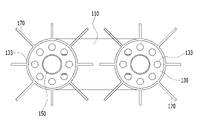
본 발명의 실시예에 따른 하이브리드 대기식 기화기(100)는 대기식 기화 파이프(110), 링 서포트(130), 히트 파이프(150), 그리고 방열 날개(170)를 포함하여 구성될 수 있다.The hybrid
본 발명의 하이브리드 대기식 기화기(100)의 외관은 도2에 도시된 바와 같이, 대기식 기화 파이프(110)가 커브진(curved) 형태로 마련되고, 대기식 기화 파이프 (110)의 둘레를 따라 대기식 기화 파이프(110)의 외표면에 방열 날개(170)가 형성되어 구현될 수 있다. 보다 구체적으로는, 방열 날개(170)는 대기식 기화 파이프(110)의 둘레에 방사상으로 형성될 수 있다.The appearance of the hybrid
도3은 본 발명의 일 실시예에 따라 하이브리드 대기식 기화기를 도시한 도2의 A-A' 단면도이다.3 is a cross-sectional view taken along line A-A' of FIG. 2 showing a hybrid atmospheric vaporizer according to an embodiment of the present invention.
본 발명의 대기식 기화 파이프(110)는 도3에 도시된 바와 같이, 내부에 링 서포트(130) 및 히트 파이프(150)가 위치할 수 있는 공간을 형성한다.As shown in FIG. 3, the
본 발명의 히트 파이프(150)는 대기식 기화 파이프(110)의 중앙에 위치할 수 있다. 더불어, 히트 파이프(150)는 링 서포트(130)의 중앙에 형성되어, 대기식 기화 파이프들(110)의 내부를 히팅시키기 위한 열원이 통과할 수 있다. 히트 파이프(150)는 상기와 같이 내부로 통과하는 열원을 이용하여, 상기 대기식 기화 파이프(110)의 온도를 조절할 수 있다.The
이때, 히트 파이프(150) 내부를 통과하는 열원은, 지열 및 공기열 중 적어도 하나일 수 있다.In this case, the heat source passing through the
그리고, 본 발명의 링 서포트(130)는 일 실시예인 도3과 같이 대기식 기화 파이프(110)의 내부에 배치되어, 히트 파이프가 관통할 수 있는 중앙 홀을 형성할 수 있다. In addition, the
또한, 본 발명의 링 서포트(130)는 대기식 기화 파이프(110)의 중앙에 위치하는 히트 파이프(150)의 원주를 따라 서로 소정의 간격 거리로 이격 배치되어, 대기식 기화 파이프(110)로 유입되는 액화 가스(LNG)를 통과시키기 위한 복수의 플로우 홀들(133)을 더 포함할 수 있다.In addition, the ring support 130 of the present invention is spaced apart from each other at a predetermined distance along the circumference of the
일 실시예에 따른 도3을 참조하면, 본 발명의 복수의 플로우 홀(133)들은 대기식 기화 파이프(110)의 중앙에 위치하는 히트 파이프(150)를 둘러싸도록 대기식 기화 파이프(110)의 중심을 기준으로 히트 파이프(150)의 외측에 위치할 수 있다.Referring to FIG. 3 according to an embodiment, a plurality of
예컨대, 본 발명의 히트 파이프(150)의 직경은, 각 플로우 홀(133)들의 직경보다 크게 형성될 수 있다.For example, the diameter of the
상술한 바와 같은 본 발명의 하이브리드 대기식 기화기(100)는 외부의 LNG가 저장된 곳으로부터 LNG를 공급받아 기화시킨다. 이러한, 하이브리드 대기식 기화기(100)는 대기를 열원으로 하여 LNG가 기화되게 하는 관 형상의 대기식 기화 파이프(110)를 사용한다. 여기서, 일 실시예에 따른 대기식 기화 파이프(110)는 원형 관으로 도시되어 있으나, 이에 한정하지 않고 다각형의 관형상으로 형성될 수 있음은 물론이다.As described above, the hybrid
본 실시예에 따른 대기식 기화 파이프(110), 히트 파이프(150), 및 방열 날개(170)의 소재는 알루미늄합금(A6061, A6163, A6063), 오스테나이트계 스테인리스강(STS304)으로 구현될 수 있다.The material of the
또한, 고압의 초저온 액체(LNG)가 흐르는 링 서포트(130)도 마찬가지로 오스테나이트계 스테인리스강의 소재로 마련될 수 있다.In addition, the
본 발명의 방열 날개(170)는 열교환 효율을 극대화하기 위하여, 4핀, 8핀, 12핀, 16핀 등의 배열 형식으로 구현될 수 있고, 그 길이와 총 전열 면적은 사용 유체의 총량에 따라 변화할 수 있다.The
방열 날개(170)들은 대기의 열을 대기식 기화 파이프(110) 내부의 LNG로 전달할 수 있다. 방열 날개(170)는 상술한 바와 같이 알루미늄이나 구리로 제작됨이 바람직하나, 이에 한정하지 않고 열전달율이 좋은 재질을 선택적으로 사용할 수 있다.The
히트 파이프(150)는 내부에 마련된 유체가 지면 내부의 지열을 열원으로 하여 가열되면서 발생된 열을 대기식 기화 파이프(110) 내부를 통과하는 액화 가스로 전달할 수 있다. The
히트 파이프(150)는 링 서포트(130)의 중앙 홀에 배치되어, 내부를 통과하는 열을 통해 히트 파이프(150) 주변을 지나는 액화 가스 및 대기식 기화 파이프(110)의 내부 온도를 효과적으로 조절할 수 있다.The
히트 파이프(150)는 지열을 열원으로 발생된 열을 대기식 기화 파이프(110)의 내부 공간으로 전달하면서 대기식 기화 파이프(110)에서 대기에 의한 LNG 기화 파이프(110) 표면이 결빙되는 것을 방지할 수 있게 한다.The
본 발명의 일 실시예에 따른 하이브리드 대기식 기화기의 LNG 기화 동작은 LNG가 저장된 외부의 저장탱크(미도시)로부터 배송라인을 통해 대기식 기화 파이프(110) 내부로 유입되고, 이렇게 대기식 기화 파이프(110) 내부로 유입된 LNG는 대기의 열에 의해 기화된 상태로 배출된다. 그리고, 배출되는 기화가스는 다시 배송라인(10)을 통해 공급될 장소로 이송된다.In the LNG vaporization operation of the hybrid atmospheric vaporizer according to an embodiment of the present invention, LNG is introduced into the
즉, 대기식 기화 파이프(110)의 내부로 히트 파이프(150)의 열이 전달되면서, 대기식 기화 파이프(110)의 표면이 결빙됨에 따라 대기식 기화 파이프(110)의 전열 효율이 낮아지는 것을 방지할 수 있게 된다.That is, as the heat of the
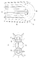
도4는 본 발명의 다른 실시예에 따른 하이브리드 대기식 기화기를 도시한 도면이다. 도4의 (a)는 하이브리드 대기식 기화기(100)의 투영도이고, 도4의 (b)는 도3과는 다른 본 발명의 하이브리드 대기식 기화기(100)의 단면도이다.4 is a view showing a hybrid atmospheric vaporizer according to another embodiment of the present invention. Fig. 4 (a) is a projection view of the hybrid
본 발명의 링 서포트(130)는 대기식 기화 파이프(110)의 내부에 삽입되는 형태로, 중앙에 있는 히트 파이프(150)를 둘러싸도록 대기식 기화 파이프(110) 내부에 형성될 수 있다.The
도4의 (b)를 참조한다. 본 발명의 일 실시예에 따르면, 대기식 기화 파이프(110)와 맞닿는 링 서포트(130)의 외측 단면은, 배관이 수축 또는 팽창되는 때를 대비하여 링 서포트(130)가 슬라이딩 가능하도록 히트 파이프(150)와 용접되지 않고 마련되는 것이 바람직하다.See Fig. 4(b). According to an embodiment of the present invention, the outer cross section of the
반면, 링 서포트(130)의 중앙 홀에 배치되는 히트 파이프(150)와 맞닿게 되는 내측단면은 히트 파이프(150)와 용접된 상태로 삽입 배치될 수 있다.On the other hand, the inner end surface that comes into contact with the
링 서포트(130)의 중앙에 형성되는 중앙 홀은 히트 파이프(150)가 관통할 수 있도록 히트 파이프(150)의 크기(직경)에 대응되는 크기로 형성되어야 한다.The central hole formed in the center of the
도5는 본 발명의 일 실시예에 따른 하이브리드 대기식 기화기의 동작에 대하여 설명하기 위해 도시한 도면이다.5 is a view for explaining the operation of the hybrid atmospheric vaporizer according to an embodiment of the present invention.
일 실시예인 도5에는 방열 날개(170)의 구성을 도시하지 않고, 대기식 기화 파이프(110) 내부에서 일어나는 동작 개념을 설명하기 위해 도식화하였다.Figure 5, which is an embodiment, does not show the configuration of the
본 실시예에 따른 하이브리드 대기식 기화기(100)의 대기식 기화 파이프(110)와 히트 파이프(150)는 도5에 도시된 바와 같이, 상/하 또는 좌/우로 굽어진 형태의 파이프로 마련될 수 있다.As shown in FIG. 5, the
초저온 액화가스(LNG)는 대기식 기화 파이프(110)의 일측으로 유입되어, 대기식 기화 파이프(110)에 의해 기화된 기화가스(NG)가 대기식 기화 파이프(110)의 타측으로 유출될 수 있다.Cryogenic liquefied gas (LNG) is introduced into one side of the
이때, 대기식 기화 파이프(110)의 내부에는 도5에 도시된 바와 같이, 링 서포트(130)가 중간 설치되어, 초저온 액화 가스(LNG)가 링 서포트(130)에 형성되어 있는 플로우 홀들(133)을 통과함에 따라 초저온 액화 가스(LNG)의 유로를 안정적으로 형성시킬 수 있다.At this time, as shown in FIG. 5 , a
본 실시예에 따른 히트 파이프(150)는 대기식 기화 파이프(110) 내부 중앙에 형성되어, 히트 파이프(150) 주변을 지나는 초저온 액화 가스(LNG) 또는 기화 가스(NG) 및 대기식 기화 파이프(110) 표면과 내부에 열을 제공함으로써, 겨울철과 외기온도가 매우 낮아지는 등과 같은 외부 환경에 의해 대기식 기화 파이프(110)의 열효율이 저하되는 현상을 방지할 수 있다.The
본 발명의 다른 실시예에 따른 하이브리드 대기식 기화기(100)는 도면에 따로 도시하지는 않았으나, 제어부를 더 포함하여 구성될 수 있다. 본 실시예에 따른 제어부는 외부 온도 또는 대기식 기화 파이프(110)의 표면 온도를 감지하여, 히트 파이프(150)의 구동을 제어할 수 있다.Although not separately shown in the drawings, the hybrid
일 예로, 제어부는 외부 온도가 제1 기준치 이하이거나, 상기 대기식 기화 파이프(110)의 표면 온도가 제2 기준치 이하인 경우, 히트 파이프(150)를 가동시켜 히트 파이프(150) 내부를 통과하는 열원에 의해 대기식 기화 파이프(110)의 온도를 조절할 수 있도록 한다.For example, when the external temperature is less than or equal to the first reference value or the surface temperature of the
예컨대, 제어부는 감지한 외부 온도가 제1 기준치 이하이거나, 대기식 기화 파이프(110)의 표면 온도가 제2 기준치 이하인 경우, 히트 파이프(150)와 열원 공급부(미도시) 사이를 차단하거나 개방하는 개폐부(미도시)의 개폐 동작을 제어함으로써, 히트 파이프(150)가 대기식 기화 파이프(110) 내부로 열원을 제공하는 동작을 제어하는 것이다.For example, the control unit blocks or opens between the
본 발명의 또 다른 실시예로, 제어부는 미리 저장된 온도 제어용 데이터를 고려하여, 감지된 외부 온도 또는 대기식 기화 파이프(110)의 온도에 따라, 상기 히트 파이프(150)로 공급되는 열원의 공급량을 제어하거나, 공급시간을 제어할 수 있다. In another embodiment of the present invention, the control unit determines the amount of heat source supplied to the
예컨대, 제어부는 감지된 외부 온도 또는 대기식 기화 파이프(110)의 온도가 상기 온도 제어용 데이터에 따른 제1 구간인 경우, 결빙 정도가 심하지 않은 것으로 판단하여 상기 개폐부(미도시)의 개폐를 소정의 각도로만 개방하거나, 소정의 시간 동안만 개폐부를 개방할 수 있고, 제어부가 감지한 외부 온도 또는 대기식 기화 파이프(110)의 온도가 상기 온도 제어용 데이터에 따른 제2 구간인 경우, 결빙 정도가 심한 것으로 판단하여 상기 개폐부(미도시)의 개폐를 완전히 개방하거나, 상기 감지된 온도가 제1 구간인 경우에 따라 개폐부가 개방한 시간보다 더 오래동안 개폐부를 개방하도록 제어할 수 있다.For example, when the sensed external temperature or the temperature of the
전술한 본 발명의 설명은 예시를 위한 것이며, 본 발명이 속하는 기술분야의 통상의 지식을 가진 자는 본 발명의 기술적 사상이나 필수적인 특징을 변경하지 않고서 다른 구체적인 형태로 쉽게 변형이 가능하다는 것을 이해할 수 있을 것이다. 그러므로 이상에서 기술한 실시예들은 모든 면에서 예시적인 것이며 한정적이 아닌 것으로 이해해야만 한다. 예를 들어, 단일형으로 설명되어 있는 각 구성 요소는 분산되어 실시될 수도 있으며, 마찬가지로 분산된 것으로 설명되어 있는 구성 요소들도 결합된 형태로 실시될 수 있다.The foregoing description of the present invention is for illustration, and those of ordinary skill in the art to which the present invention pertains can understand that it can be easily modified into other specific forms without changing the technical spirit or essential features of the present invention. will be. Therefore, it should be understood that the embodiments described above are illustrative in all respects and not restrictive. For example, each component described as a single type may be implemented in a distributed manner, and likewise components described as distributed may also be implemented in a combined form.
본 발명의 범위는 후술하는 청구범위에 의하여 나타내어지며, 청구범위의 의미 및 범위 그리고 그 균등 개념으로부터 도출되는 모든 변경 또는 변형된 형태가 본 발명의 범위에 포함되는 것으로 해석되어야 한다.The scope of the present invention is indicated by the following claims, and all changes or modifications derived from the meaning and scope of the claims and their equivalents should be construed as being included in the scope of the present invention.
100: 하이브리드 대기식 기화기
110: 대기식 기화 파이프
130: 링 서포트
133: 플로우 홀
150: 히트 파이프
170: 방열 날개100: hybrid atmospheric carburetor
110: atmospheric vaporization pipe
130: ring support
133: flow hole
150: heat pipe
170: heat dissipation wing
Claims (7)
상기 기화 파이프의 내부에 형성되며, 내부를 통과하는 열원을 이용하여 상기 기화 파이프의 온도를 조절하는 히트 파이프와,
상기 대기식 기화 파이프 내부에 배치되어, 상기 히트 파이프가 관통할 수 있는 중앙 홀을 형성하는 링 서포트를 포함하는 것을 특징으로 하는 하이브리드 대기식 기화기.
An atmospheric vaporization pipe for vaporizing the incoming liquefied gas,
a heat pipe formed inside the vaporization pipe and controlling the temperature of the vaporization pipe by using a heat source passing through the interior;
and a ring support disposed inside the atmospheric vaporization pipe to form a central hole through which the heat pipe may pass.
상기 링 서포트는 서로 소정의 간격 거리로 이격되어 상기 유입되는 액화가스를 통과시키기 위한 복수의 플로우 홀들을 포함하고,
상기 복수의 플로우 홀들은 상기 히트 파이프 또는 상기 대기식 기화 파이프의 원주를 따라 배열되는 것을 특징으로 하는 하이브리드 대기식 기화기.
According to claim 1,
The ring support is spaced apart from each other by a predetermined distance and includes a plurality of flow holes for passing the flowing liquefied gas,
The plurality of flow holes are hybrid atmospheric vaporizer, characterized in that arranged along a circumference of the heat pipe or the atmospheric vaporization pipe.
상기 히트 파이프는 상기 대기식 기화 파이프의 중앙에 위치하며,
상기 복수의 플로우 홀들은 상기 히트 파이프를 둘러싸도록 상기 대기식 기화 파이프의 중심을 기준으로 상기 히트 파이프의 외표면에 인접하여 형성되는 것을 특징으로 하는 하이브리드 대기식 기화기.
3. The method of claim 2,
The heat pipe is located in the center of the atmospheric vaporization pipe,
The plurality of flow holes are hybrid atmospheric vaporizer, characterized in that formed adjacent to the outer surface of the heat pipe with respect to the center of the atmospheric vaporization pipe to surround the heat pipe.
상기 히트 파이프의 직경은 상기 적어도 하나의 상기 플로우 홀의 직경보다 크게 형성되는 것을 특징으로 하는 하이브리드 대기식 기화기.
3. The method of claim 2,
A hybrid atmospheric vaporizer, characterized in that the diameter of the heat pipe is larger than the diameter of the at least one flow hole.
상기 중앙 홀은 상기 히트 파이프가 위치할 수 있도록 상기 히트 파이프의 크기에 대응되는 것을 특징으로 하는 하이브리드 대기식 기화기.
3. The method of claim 2,
The central hole is a hybrid atmospheric vaporizer, characterized in that it corresponds to the size of the heat pipe so that the heat pipe can be located.
상기 대기식 기화 파이프의 둘레에 방사상으로 형성되는 복수개의 방열 날개들을 더 포함하는 것을 특징으로 하는 하이브리드 대기식 기화기.
According to claim 1,
Hybrid atmospheric vaporizer, characterized in that it further comprises a plurality of radiating blades radially formed around the atmospheric vaporization pipe.
상기 히트 파이프를 통과하는 열원은, 지열 및 공기열 중 적어도 하나로 사용되는 것을 특징으로 하는 하이브리드 대기식 기화기.
According to claim 1,
The heat source passing through the heat pipe is a hybrid atmospheric vaporizer, characterized in that used as at least one of geothermal heat and air heat.
Priority Applications (1)
| Application Number | Priority Date | Filing Date | Title |
|---|---|---|---|
| KR1020210025390A KR102565176B1 (en) | 2021-02-25 | 2021-02-25 | Hybrid ambient air vaporizer |
Applications Claiming Priority (1)
| Application Number | Priority Date | Filing Date | Title |
|---|---|---|---|
| KR1020210025390A KR102565176B1 (en) | 2021-02-25 | 2021-02-25 | Hybrid ambient air vaporizer |
Publications (2)
| Publication Number | Publication Date |
|---|---|
| KR20220121402A true KR20220121402A (en) | 2022-09-01 |
| KR102565176B1 KR102565176B1 (en) | 2023-08-11 |
Family
ID=83281898
Family Applications (1)
| Application Number | Title | Priority Date | Filing Date |
|---|---|---|---|
| KR1020210025390A KR102565176B1 (en) | 2021-02-25 | 2021-02-25 | Hybrid ambient air vaporizer |
Country Status (1)
| Country | Link |
|---|---|
| KR (1) | KR102565176B1 (en) |
Citations (3)
| Publication number | Priority date | Publication date | Assignee | Title |
|---|---|---|---|---|
| JP2011080495A (en) * | 2009-10-05 | 2011-04-21 | National Institute Of Advanced Industrial Science & Technology | Hydrogen heat exchanger for hydrogen filling system |
| KR200472614Y1 (en) * | 2012-07-09 | 2014-05-09 | 삼성중공업 주식회사 | double pipe |
| KR101506946B1 (en) * | 2014-12-11 | 2015-04-07 | 주식회사 태진중공업 | High Pressure Ambient Air Vaporizer And Seamless Pipe, Pin Tube Connection Method Used To Air Vaporizer |
-
2021
- 2021-02-25 KR KR1020210025390A patent/KR102565176B1/en active IP Right Grant
Patent Citations (3)
| Publication number | Priority date | Publication date | Assignee | Title |
|---|---|---|---|---|
| JP2011080495A (en) * | 2009-10-05 | 2011-04-21 | National Institute Of Advanced Industrial Science & Technology | Hydrogen heat exchanger for hydrogen filling system |
| KR200472614Y1 (en) * | 2012-07-09 | 2014-05-09 | 삼성중공업 주식회사 | double pipe |
| KR101506946B1 (en) * | 2014-12-11 | 2015-04-07 | 주식회사 태진중공업 | High Pressure Ambient Air Vaporizer And Seamless Pipe, Pin Tube Connection Method Used To Air Vaporizer |
Also Published As
| Publication number | Publication date |
|---|---|
| KR102565176B1 (en) | 2023-08-11 |
Similar Documents
| Publication | Publication Date | Title |
|---|---|---|
| US7155917B2 (en) | Apparatus and methods for converting a cryogenic fluid into gas | |
| JP6273472B2 (en) | Cold-heat recovery device using LNG fuel and liquefied gas carrier having the same | |
| KR101473908B1 (en) | A plant for regasification of lng | |
| KR101151094B1 (en) | Ambient air vaporizer | |
| FR2993342A1 (en) | INSTALLATION AND METHOD FOR FILLING PRESSURE GAS BOTTLES FROM A LIQUEFIED GAS RESERVOIR | |
| KR101588663B1 (en) | Device for supplying fuel gas in ships | |
| US10871312B2 (en) | Transport refrigeration unit with vented cryogenic cooling | |
| JP2006349133A (en) | Low temperature liquefied gas storing device, and power generating device and movable body having the same | |
| US20210356196A1 (en) | Vaporizer with Defrosting Function | |
| JP5039846B1 (en) | Vaporizer for liquefied gas | |
| KR20220121402A (en) | Hybrid ambient air vaporizer | |
| JP2015534024A (en) | Environmental Air Vaporizer and Configuration and Method for Cold Use | |
| JP6092065B2 (en) | Liquefied gas vaporization system and liquefied gas vaporization method | |
| CN109186157A (en) | A kind of efficient liquefied natural gas vaporization phase change cold-storage device | |
| RO130699A2 (en) | Pumping and vaporization system for improved oil recovery applications | |
| JP4625650B2 (en) | Low temperature liquefied gas supply device | |
| JP2009103165A (en) | Low temperature liquefied gas transport vehicle | |
| JP6126569B2 (en) | Vaporizer for liquefied gas | |
| KR101864153B1 (en) | Liquefied gas regasification system | |
| WO2019082096A1 (en) | Plant for the liquefaction of gas, particularly network gas | |
| JP7126024B2 (en) | Fluid tank with internal evaporator | |
| CN216307406U (en) | Low-temperature liquid nitrogen flat-bottom storage tank with interlayer self-supply protective gas system | |
| CN215000094U (en) | Connecting structure of low-temperature pipeline and normal-temperature shell | |
| KR101824423B1 (en) | Liquefied gas regasification system | |
| KR20150062566A (en) | Lng regasification facility using waste heat of ship |
Legal Events
| Date | Code | Title | Description |
|---|---|---|---|
| E902 | Notification of reason for refusal | ||
| E701 | Decision to grant or registration of patent right |