KR20220121115A - Cooking appliance - Google Patents
Cooking appliance Download PDFInfo
- Publication number
- KR20220121115A KR20220121115A KR1020210025145A KR20210025145A KR20220121115A KR 20220121115 A KR20220121115 A KR 20220121115A KR 1020210025145 A KR1020210025145 A KR 1020210025145A KR 20210025145 A KR20210025145 A KR 20210025145A KR 20220121115 A KR20220121115 A KR 20220121115A
- Authority
- KR
- South Korea
- Prior art keywords
- cavity
- exhaust
- exhaust port
- duct
- blocking
- Prior art date
Links
- 238000010411 cooking Methods 0.000 title claims abstract description 168
- 230000000903 blocking effect Effects 0.000 claims abstract description 144
- XLYOFNOQVPJJNP-UHFFFAOYSA-N water Substances O XLYOFNOQVPJJNP-UHFFFAOYSA-N 0.000 claims abstract description 56
- 238000010438 heat treatment Methods 0.000 claims description 33
- 230000008878 coupling Effects 0.000 claims description 20
- 238000010168 coupling process Methods 0.000 claims description 20
- 238000005859 coupling reaction Methods 0.000 claims description 20
- 238000000034 method Methods 0.000 claims description 14
- 239000007789 gas Substances 0.000 description 37
- 235000013305 food Nutrition 0.000 description 27
- 239000000567 combustion gas Substances 0.000 description 12
- 230000035515 penetration Effects 0.000 description 8
- 239000000446 fuel Substances 0.000 description 6
- 230000008569 process Effects 0.000 description 6
- UGFAIRIUMAVXCW-UHFFFAOYSA-N Carbon monoxide Chemical compound [O+]#[C-] UGFAIRIUMAVXCW-UHFFFAOYSA-N 0.000 description 4
- 235000021186 dishes Nutrition 0.000 description 4
- 230000005611 electricity Effects 0.000 description 4
- 238000009434 installation Methods 0.000 description 4
- 238000001816 cooling Methods 0.000 description 3
- 238000005192 partition Methods 0.000 description 3
- 238000009423 ventilation Methods 0.000 description 3
- 238000005452 bending Methods 0.000 description 2
- 230000008901 benefit Effects 0.000 description 2
- 229910002091 carbon monoxide Inorganic materials 0.000 description 2
- 230000000694 effects Effects 0.000 description 2
- 230000014509 gene expression Effects 0.000 description 2
- 230000005484 gravity Effects 0.000 description 2
- 230000006698 induction Effects 0.000 description 2
- 230000000149 penetrating effect Effects 0.000 description 2
- 241000251468 Actinopterygii Species 0.000 description 1
- 208000027418 Wounds and injury Diseases 0.000 description 1
- 230000009471 action Effects 0.000 description 1
- 235000021168 barbecue Nutrition 0.000 description 1
- 238000009835 boiling Methods 0.000 description 1
- 235000008429 bread Nutrition 0.000 description 1
- 239000000919 ceramic Substances 0.000 description 1
- 230000006378 damage Effects 0.000 description 1
- 230000002950 deficient Effects 0.000 description 1
- 238000007599 discharging Methods 0.000 description 1
- 238000005516 engineering process Methods 0.000 description 1
- 208000014674 injury Diseases 0.000 description 1
- 238000011900 installation process Methods 0.000 description 1
- 239000000463 material Substances 0.000 description 1
- 230000004048 modification Effects 0.000 description 1
- 238000012986 modification Methods 0.000 description 1
- 239000012466 permeate Substances 0.000 description 1
- 238000000638 solvent extraction Methods 0.000 description 1
- 230000007480 spreading Effects 0.000 description 1
Images


Classifications
-
- F—MECHANICAL ENGINEERING; LIGHTING; HEATING; WEAPONS; BLASTING
- F24—HEATING; RANGES; VENTILATING
- F24C—DOMESTIC STOVES OR RANGES ; DETAILS OF DOMESTIC STOVES OR RANGES, OF GENERAL APPLICATION
- F24C15/00—Details
- F24C15/32—Arrangements of ducts for hot gases, e.g. in or around baking ovens
-
- F—MECHANICAL ENGINEERING; LIGHTING; HEATING; WEAPONS; BLASTING
- F24—HEATING; RANGES; VENTILATING
- F24C—DOMESTIC STOVES OR RANGES ; DETAILS OF DOMESTIC STOVES OR RANGES, OF GENERAL APPLICATION
- F24C15/00—Details
- F24C15/20—Removing cooking fumes
- F24C15/2007—Removing cooking fumes from oven cavities
-
- F—MECHANICAL ENGINEERING; LIGHTING; HEATING; WEAPONS; BLASTING
- F24—HEATING; RANGES; VENTILATING
- F24C—DOMESTIC STOVES OR RANGES ; DETAILS OF DOMESTIC STOVES OR RANGES, OF GENERAL APPLICATION
- F24C15/00—Details
- F24C15/14—Spillage trays or grooves
-
- F—MECHANICAL ENGINEERING; LIGHTING; HEATING; WEAPONS; BLASTING
- F24—HEATING; RANGES; VENTILATING
- F24C—DOMESTIC STOVES OR RANGES ; DETAILS OF DOMESTIC STOVES OR RANGES, OF GENERAL APPLICATION
- F24C15/00—Details
- F24C15/20—Removing cooking fumes
- F24C15/2021—Arrangement or mounting of control or safety systems
-
- F—MECHANICAL ENGINEERING; LIGHTING; HEATING; WEAPONS; BLASTING
- F24—HEATING; RANGES; VENTILATING
- F24C—DOMESTIC STOVES OR RANGES ; DETAILS OF DOMESTIC STOVES OR RANGES, OF GENERAL APPLICATION
- F24C3/00—Stoves or ranges for gaseous fuels
- F24C3/008—Ranges
-
- F—MECHANICAL ENGINEERING; LIGHTING; HEATING; WEAPONS; BLASTING
- F24—HEATING; RANGES; VENTILATING
- F24C—DOMESTIC STOVES OR RANGES ; DETAILS OF DOMESTIC STOVES OR RANGES, OF GENERAL APPLICATION
- F24C3/00—Stoves or ranges for gaseous fuels
- F24C3/08—Arrangement or mounting of burners
- F24C3/085—Arrangement or mounting of burners on ranges
-
- F—MECHANICAL ENGINEERING; LIGHTING; HEATING; WEAPONS; BLASTING
- F24—HEATING; RANGES; VENTILATING
- F24C—DOMESTIC STOVES OR RANGES ; DETAILS OF DOMESTIC STOVES OR RANGES, OF GENERAL APPLICATION
- F24C3/00—Stoves or ranges for gaseous fuels
- F24C3/10—Arrangement or mounting of ignition devices
Abstract
Description
본 발명은 조리기기에 관한 것으로, 더욱 상세하게는 쿡탑부와 오븐부를 함께 구비하는 조리기기에 관한 것이다.The present invention relates to a cooking appliance, and more particularly, to a cooking appliance having a cooktop unit and an oven unit together.
조리기기는, 음식물을 요리하기 위한 가전기기의 하나로써 주방 공간에 설치되어 사용자의 의도에 따라 음식물을 요리하는 기기이다. 이러한 조리기기는 사용되는 열원 또는 형태, 연료의 종류에 따라 다양하게 분류할 수 있다.A cooking appliance is one of home appliances for cooking food and is installed in a kitchen space to cook food according to a user's intention. These cooking appliances may be classified in various ways according to the type of heat source or type used, and fuel.
조리기기를 음식물을 조리하는 형태에 따라 분류하여 보면, 음식물이 놓이는 공간의 형태에 따라 개방형과 밀폐형 조리기기로 분류할 수 있다. 밀폐형 조리기기에는 오븐, 전자레인지 등이 있으며, 개방형 조리기기에는 쿡탑, 홉, 그리들 등이 있다.When cooking appliances are classified according to a type of cooking, they can be classified into open-type and closed-type cooking appliances according to the shape of a space in which food is placed. The closed cooking appliance includes an oven, a microwave oven, and the like, and the open cooking appliance includes a cooktop, a hop, a griddle, and the like.
밀폐형 조리기기는, 음식물이 위치하는 공간을 차폐하고, 차폐된 공간을 가열하여 음식물을 요리하는 조리기기이다. 밀폐형 조리기기에는, 음식물이 놓이면서 음식물을 요리하고자 할 때 차폐되는 공간인 조리실이 제공된다. 이러한 조리실은, 실질적으로 음식물이 요리되는 공간이 된다.The sealed cooking appliance is a cooking appliance that shields a space in which food is located and heats the shielded space to cook food. In the sealed cooking appliance, a cooking chamber, which is a space that is shielded when food is placed while cooking food, is provided. Such a cooking chamber becomes a space in which food is substantially cooked.
상기 밀폐형 조리기기는, 열원(熱源)의 종류에 따라 가스 오븐과 전기 오븐으로 대별된다. 가스 오븐은, 가스를 연료로 사용하게 되며, 다수의 버너에 가스를 공급하여 점화시킴으로써 공급되는 가스가 타면서 발생되는 불꽃에 의해 음식물을 요리하는 방식을 취하게 된다. 전기 오븐은, 가스 오븐과 달리 전기를 열원으로 하며, 다수의 히터가 작동되면서 히터에서 발산되는 열에 의해 음식물을 요리하는 방식을 취하게 된다.The sealed cooking appliance is roughly classified into a gas oven and an electric oven according to a type of a heat source. The gas oven uses gas as a fuel, and by supplying gas to a plurality of burners and igniting the gas oven, food is cooked by a flame generated while the supplied gas is burned. Unlike a gas oven, an electric oven uses electricity as a heat source and cooks food by heat emitted from the heaters while a plurality of heaters are operated.
밀폐형 조리기기에는, 조리실을 선택적으로 개폐하는 도어가 회동 가능하게 제공될 수 있다. 도어는, 내부에 조리실이 형성된 본체와 도어 사이에 마련되는 도어 힌지에 의해 본체에 회동 가능하게 설치되며, 도어 힌지를 통해 본체와 결합된 부분을 중심으로 회동함으로써 조리실을 선택적으로 개폐할 수 있다.In the sealed cooking appliance, a door for selectively opening and closing the cooking chamber may be rotatably provided. The door is rotatably installed on the main body by a door hinge provided between the main body in which the cooking chamber is formed and the door, and the cooking chamber can be selectively opened and closed by rotating around a portion coupled to the main body through the door hinge.
상기 도어에 의해 개폐되는 조리실의 내부 공간에는 열원이 제공되어 조리실을 가열한다. 이러한 열원으로는 가스버너 또는 전기히터 등이 이용될 수 있다.A heat source is provided to the inner space of the cooking compartment opened and closed by the door to heat the cooking compartment. As such a heat source, a gas burner or an electric heater may be used.
아울러 밀폐형 조리기기에는, 배기덕트가 구비된다. 배기덕트는, 조리실 내부에서 음식물을 조리하는 과정에서 발생되는 연소가스를 조리기기 외부로 배출하기 위해 마련된다.In addition, the sealed cooking appliance is provided with an exhaust duct. The exhaust duct is provided to discharge combustion gas generated in the process of cooking food in the cooking chamber to the outside of the cooking appliance.
이러한 배기덕트는, 그 하단부가 조리실의 상부와 연결되고 상단부가 조리기기의 후면 상부 측에 배치되도록 마련된다. 조리실에서 발생되는 연소가스는, 조리실의 상부에 연결된 배기덕트로 유입되어 상부로 유동되며, 배기덕트의 상부에 마련된 벤트그릴을 통해 조리기기의 후면에서 상부방향으로 배출된다.The exhaust duct is provided such that a lower end thereof is connected to an upper portion of the cooking chamber and an upper end thereof is disposed on the rear upper side of the cooking appliance. The combustion gas generated in the cooking chamber is introduced into an exhaust duct connected to the upper portion of the cooking chamber, flows upward, and is discharged upwardly from the rear surface of the cooking appliance through a vent grill provided on the upper portion of the exhaust duct.
벤트그릴에는 배기덕트를 통해 배출되는 연소가스를 통과시키기 위한 적어도 하나의 배기홀이 마련되며, 이러한 배기홀은 벤트그릴에 상하방향으로 관통되게 형성된다.At least one exhaust hole for passing the combustion gas discharged through the exhaust duct is provided in the vent grill, and these exhaust holes are formed to penetrate through the vent grill in the vertical direction.
근래에는 밀폐형 조리기기와 개방형 조리기기가 동시에 설치되어 다수의 열원이 조합되면서 다양한 음식물의 요리 및 다수의 음식물을 동시에 요리할 수 있는 복합조리기기가 제안되고 있다. 이러한 다수의 열원이 설치되는 조리기기에는, 다수의 열원 및 전장 부품을 냉각하기 위한 냉각 공기의 유로가 동반된다.In recent years, a closed-type cooking device and an open-type cooking device are installed at the same time to combine a plurality of heat sources, and a complex cooking device capable of cooking various foods and cooking a plurality of foods at the same time has been proposed. A cooking appliance in which such a plurality of heat sources are installed is accompanied by a flow path of cooling air for cooling the plurality of heat sources and electronic components.
복합조리기기에서는, 밀폐형 조리기기의 상측에 개방형 조리기기가 위치된다. 또한 개방형 조리기기에는, 복수 개의 히터 또는 버너가 설치되어 동시에 다수의 요리가 가능하도록 설치된다.In the combined cooking appliance, an open cooking appliance is positioned above the closed cooking appliance. In addition, a plurality of heaters or burners are installed in the open cooking appliance to enable a plurality of dishes at the same time.
즉 사용자가 바베큐요리나 빵 등과 같은 오븐요리, 생선구이와 같이 구이요리를 할 때에는 밀폐형 조리기기를 이용하여 조리를 하게 되고, 음식물을 용기에 담아서 가열하는 일반요리를 할 때는 상부에 노출되어 있는 개방형 조리기기를 이용하여 요리를 하게 된다.In other words, when the user cooks oven dishes such as barbecue dishes or bread, or grilling dishes such as grilled fish, he uses a closed cooking device. Cooking is done using cooking equipment.
개방형 조리기기 중 대표적으로 많이 이용되는 것은, 가스레인지 형태의 개방형 조리기기로서, 버너에 의해 가스가 연소될 때 발생되는 화염을 이용하여 음식물을 조리하는 기기이다.One of the most commonly used open cookers is a gas range type open cooker that cooks food using a flame generated when gas is burned by a burner.
이러한 형태의 개방형 조리기기에 구비되는 버너는, 크게 버너바디, 버너헤드 및 버너헤드캡을 포함하는 구성을 갖는 것이 일반적이다.A burner provided in this type of open cooking appliance generally has a configuration including a burner body, a burner head, and a burner head cap.
이에 따르면, 개방형 조리기기의 외형을 형성하는 쿡탑케이스 내부에 가스가 공급되는 유로가 형성된 버너바디가 고정되게 설치되고, 버너바디의 상부에는 유로를 통해 공급된 가스가 배출되는 버너헤드가 설치되며, 버너헤드캡은 버너헤드의 상부에 설치된다.According to this, a burner body having a flow path through which gas is supplied is fixedly installed inside the cooktop case forming the outer shape of the open cooking appliance, and a burner head through which the gas supplied through the flow path is discharged is installed on the upper portion of the burner body, The burner head cap is installed on the upper part of the burner head.
버너바디에는, 가스의 공급을 위한 가스공급관 및 가스의 분사를 위한 노즐 등이 장착될 수 있다. 그리고 버너헤드는 개방형 조리기기의의 상면을 정의하는 부재, 예를 들면 탑플레이트의 상면에 위치할 수 있고, 버너헤드캡이 버너헤드의 상측에 안착된다.A gas supply pipe for supplying gas and a nozzle for injecting gas may be mounted on the burner body. In addition, the burner head may be located on a member defining the upper surface of the open cooking appliance, for example, the upper surface of the top plate, and the burner head cap is seated on the upper side of the burner head.
상기 복합조리기기에서, 벤트그릴은 통상적으로 개방형 조리기기의 후면 상부 측에 배치된다. 예컨대, 배기덕트의 상단부는 탑플레이트를 관통하며 개방형 조리기기의 후면 측에 배치될 수 있고, 벤트그릴은 그 상부, 즉 탑플레이트의 후면 상부 측에 배치될 수 있다.In the combined cooking appliance, the vent grill is typically disposed on the upper rear side of the open cooking appliance. For example, the upper end of the exhaust duct passes through the top plate and may be disposed on the rear side of the open cooking appliance, and the vent grill may be disposed on the upper side thereof, that is, on the rear upper side of the top plate.
한편, 배기덕트의 하단부는, 캐비티의 상부면과 연결될 수 있다. 캐비티의 상부면에는 배기구가 상하방향으로 관통되게 형성될 수 있으며, 배기덕트는 이 배기구를 통해 조리실 내부와 연결될 수 있다.Meanwhile, the lower end of the exhaust duct may be connected to the upper surface of the cavity. An exhaust port may be formed to pass through the upper surface of the cavity in a vertical direction, and the exhaust duct may be connected to the inside of the cooking chamber through the exhaust port.
조리실의 내부 공간에는 열원이 제공되어 조리실을 가열하며, 이러한 열원으로 가스버너 또는 전기히터 등이 이용될 수 있다. 이 중 브로일 버너나 브로일 히터와 같이 조리실의 상측에 배치되는 열원은 배기구와 인접한 위치에 배치되며, 이러한 열원의 적어도 일부분은 배기구의 하부에 배치된다.A heat source is provided in the inner space of the cooking compartment to heat the cooking compartment, and a gas burner or an electric heater may be used as the heat source. Among them, a heat source disposed above the cooking chamber, such as a broil burner or a broil heater, is disposed adjacent to the exhaust port, and at least a portion of the heat source is disposed below the exhaust port.
상기 구조에 따르면, 벤트그릴의 배기홀을 통해 물이 배기덕트의 내부로 유입될 수 있다. 그리고 이처럼 배기덕트의 내부로 유입된 물은, 배기덕트의 하부에 배치된 열원 측으로 침투할 수 있다.According to the structure, water may be introduced into the exhaust duct through the exhaust hole of the vent grill. In addition, the water introduced into the exhaust duct in this way may permeate toward the heat source disposed under the exhaust duct.
이와 같이 열원 측으로 침투한 물은, 열원의 정상적인 점화나 작동에 영향을 줄 수 있다. 예컨대, 브로일 히터의 전기 접속부에 물이 침투할 경우 안전사고가 발생될 위험성이 높아지게 되고, 브로일 버너의 점화장치(Ignitor)로 물이 침투할 경우, 브로일 버너의 점화 불량이 발생될 위험성이 높아지게 된다.The water that has penetrated toward the heat source in this way may affect the normal ignition or operation of the heat source. For example, if water penetrates into the electrical connection part of the broil heater, the risk of a safety accident increases, and if water penetrates into the ignitor of the broil burner, there is a risk of ignition failure of the broil burner. this will increase
본 발명은 조리기기 외부에서 배기덕트를 통해 유입된 물이 열원으로 침투하는 것을 차단할 수 있도록 구조가 개선된 조리기기를 제공하는데 그 목적이 있다.An object of the present invention is to provide a cooking appliance having an improved structure so that water introduced through an exhaust duct from the outside of the cooking appliance can be blocked from penetrating into a heat source.
또한 본 발명의 다른 목적은, 브로일 버너의 점화 불량 발생이 억제되도록 구조가 개선된 조리기기를 제공하는데 있다.Another object of the present invention is to provide a cooking appliance having an improved structure so that the occurrence of ignition failure of the broil burner is suppressed.
상기 목적을 이루기 위한 본 발명의 일 실시 형태인 조리기기는, 배기덕트의 내부에는 일측이 배기구를 통해 조리실의 내부와 연결되고 타측이 탑플레이트 상부로 개방되는 배기유로가 형성되며, 이러한 배기유로가 형성된 배기덕트의 내부에는 배기유로에서 배기구를 향해 흘러내리는 물의 이동 경로 중 적어도 일부를 가로막는 차단부가 구비되는 것을 특징으로 한다.In the cooking appliance according to an embodiment of the present invention for achieving the above object, an exhaust flow path is formed in the exhaust duct, one side of which is connected to the inside of the cooking chamber through an exhaust port and the other side is opened to the upper part of the top plate. The formed exhaust duct is characterized in that a blocking portion for blocking at least a portion of the movement path of water flowing down from the exhaust flow path toward the exhaust port is provided.
이처럼 구비된 차단부를 이용하여 배기유로에서 배기구를 통한 점화장치로의 물의 유동 경로를 막음으로써, 조리기기 외부에서 배기덕트를 통해 유입된 물의 열원으로의 침투가 효과적으로 차단될 수 있다.By blocking the flow path of water from the exhaust passage to the ignition device through the exhaust port by using the blocking unit provided as described above, penetration of water introduced through the exhaust duct from the outside of the cooking appliance into the heat source can be effectively blocked.
또한 본 발명의 다른 형태는, 배기유로의 상단과 점화장치 사이에 차단부가 배치되고, 이 차단부는 배기유로에서 점화장치를 향해 흘러내리는 물의 이동 경로를 가로막는 것을 특징으로 한다.Another aspect of the present invention is characterized in that a blocking part is disposed between the upper end of the exhaust flow path and the ignition device, and the blocking part blocks a movement path of water flowing from the exhaust flow path toward the ignition device.
이를 통해, 배기유로에서 배기구를 통한 점화장치로의 물의 유동 경로가 차단부에 의해 차단될 수 있으며, 결과적으로 브로일 버너의 점화 불량 발생이 효과적으로 억제될 수 있다.Through this, the flow path of water from the exhaust flow path to the ignition device through the exhaust port can be blocked by the blocking unit, and as a result, the occurrence of ignition failure of the broil burner can be effectively suppressed.
본 발명의 일 측면에 따른 조리기기는: 내부에 조리실이 형성되는 캐비티를 포함하는 오븐부와; 상기 캐비티와의 사이에 상부공간이 형성되도록 상기 캐비티의 상부를 덮는 탑플레이트, 및 적어도 일부분이 상기 상부공간에 배치되는 적어도 하나의 쿡탑가열부를 포함하는 쿡탑부; 및 상기 조리실의 내부를 상기 탑플레이트의 상부와 연결하는 통로를 형성하는 배기덕트;를 포함하고, 상기 오븐부는 상기 쿡탑부와 마주보는 상기 캐비티의 일측면에 상하방향으로 관통되게 형성되는 배기구를 포함하고, 상기 배기덕트의 내부에는 일측이 상기 배기구와 연결되고 타측이 상기 탑플레이트 상부로 개방되는 배기유로가 형성되고, 상기 배기덕트의 내부에는 상기 배기유로에서 상기 배기구를 향해 흘러내리는 물의 이동 경로 중 적어도 일부를 가로막는 차단부가 구비될 수 있다.According to one aspect of the present invention, a cooking appliance includes: an oven unit including a cavity having a cooking chamber formed therein; a cooktop unit including a top plate covering an upper portion of the cavity to form an upper space therebetween, and at least one cooktop heating unit at least a portion of which is disposed in the upper space; and an exhaust duct for forming a passage connecting the inside of the cooking chamber to the upper portion of the top plate, wherein the oven unit includes an exhaust port formed to penetrate vertically through one side of the cavity facing the cooktop unit and an exhaust passage having one side connected to the exhaust port and the other side open to the top of the top plate is formed in the exhaust duct, and inside the exhaust duct, water flowing down from the exhaust passage toward the exhaust port is formed. A blocking part blocking at least a part may be provided.
또한 상기 차단부는, 상기 배기유로의 타측과 상기 배기구 사이에 배치되며, 상기 캐비티의 일측면으로부터 세로방향으로 돌출되게 구비되는 것이 바람직하다.In addition, the blocking part may be disposed between the other side of the exhaust passage and the exhaust port, and may be provided to protrude vertically from one side of the cavity.
또한 상기 차단부는, 상기 캐비티의 일측면의 상부에 마련되되, 수직방향으로 돌출되게 형성되는 것이 바람직하다.In addition, the blocking portion is provided on the upper portion of one side of the cavity, it is preferable that it is formed to protrude in the vertical direction.
또한 상기 차단부는, 상기 캐비티와 일체로 형성되는 것이 바람직하다.In addition, the blocking portion is preferably formed integrally with the cavity.
또한 상기 캐비티의 일측면의 일부분이 상하방향으로 타공되어 상기 배기구가 형성되고, 상기 차단부는 상기 배기구를 둘러싸는 상기 캐비티의 테두리 중 일부분이 상부방향으로 연장된 형태로 형성되는 것이 바람직하다.In addition, it is preferable that a portion of one side of the cavity is perforated in the vertical direction to form the exhaust port, and the blocking part is formed in a form in which a portion of an edge of the cavity surrounding the exhaust port extends upward.
또한 본 발명은 상기 조리실의 내부에 배치되는 버너를 더 포함하고,In addition, the present invention further includes a burner disposed inside the cooking chamber,
상기 버너는 상기 배기구의 하부에 배치되는 점화장치를 포함하고,The burner includes an ignition device disposed under the exhaust port,
상기 차단부는 상기 배기유로의 타측과 상기 점화장치 사이에 배치되어 상기 배기유로에서 상기 점화장치를 향해 흘러내리는 물의 이동 경로를 가로막는 것이 바람직하다.Preferably, the blocking part is disposed between the other side of the exhaust flow path and the ignition device to block a movement path of water flowing from the exhaust flow path toward the ignition device.
또한 상기 차단부는 상기 점화장치의 후방에 배치되고, 상기 차단부의 좌우방향 폭이 상기 점화장치의 좌우방향 폭보다 크고, 상기 차단부는 상기 점화장치보다 좌우방향으로 더 돌출되게 형성되는 것이 바람직하다.In addition, it is preferable that the blocking part is disposed at the rear of the ignition device, the width of the blocking part in the left and right directions is greater than the width in the left and right directions of the ignition device, and the blocking part is formed to protrude more in the left and right directions than the ignition device.
또한 상기 배기덕트는, 상기 배기구와 연결되는 제1배기유로가 내부에 형성되는 제1덕트부, 및 일측이 상기 제1배기유로와 연결되며 타측이 상기 배기구 상부로 개방되는 제2배기유로가 내부에 형성되는 제2덕트부를 포함하고,In addition, the exhaust duct includes a first duct portion having a first exhaust passage connected to the exhaust port formed therein, and a second exhaust passage having one side connected to the first exhaust passage and the other side open to the upper portion of the exhaust port. Including a second duct portion formed in,
상기 제2덕트부는 상기 배기구보다 후방에 배치되고, 상기 제1덕트부는 상기 배기구로부터 상기 제2덕트부 측으로 상향 경사지게 연장되고, 상기 차단부는 상기 제1덕트부의 내부에 배치되는 것이 바람직하다.Preferably, the second duct part is disposed behind the exhaust port, the first duct part is inclined upwardly from the exhaust port toward the second duct part, and the blocking part is disposed inside the first duct part.
또한 상기 제1덕트부는 상기 캐비티의 일측면과 상기 제2덕트부 사이를 연결하는 복수개의 측벽을 포함하고, 상기 복수개의 측벽이 전후좌우방향으로 상기 제1배기유로를 둘러싸며 서로 연결되고, 상기 차단부는 상기 복수개의 측벽 중 최후방에 배치되는 측벽인 후방측벽과 상기 배기구 사이에 배치되는 것이 바람직하다.In addition, the first duct part includes a plurality of sidewalls connecting one side of the cavity and the second duct part, and the plurality of sidewalls surround the first exhaust flow path in front, rear, left, right directions and are connected to each other, and Preferably, the blocking part is disposed between the rear side wall, which is the rearmost side wall among the plurality of side walls, and the exhaust port.
또한 상기 후방측벽과 상기 배기구 사이가 상기 캐비티의 일측면에 의해 연결되고, 상기 차단부는 상기 캐비티의 일측면으로부터 상측으로 돌출되게 형성되는 것이 바람직하다.In addition, it is preferable that the rear side wall and the exhaust port are connected by one side of the cavity, and the blocking part is formed to protrude upward from one side of the cavity.
또한 상기 제1덕트부는 상기 복수개의 측벽으로부터 돌출되어 상기 캐비티의 일측면과 결합되는 결합부를 더 포함하고, 상기 결합부는 상기 복수개의 측벽 중 적어도 어느 하나의 하단으로부터 상기 캐비티의 일측면과 나란한 방향으로 돌출되게 형성되는 것이 바람직하다.In addition, the first duct part further includes a coupling part protruding from the plurality of sidewalls to be coupled to one side of the cavity, and the coupling part from the lower end of at least one of the plurality of sidewalls in a direction parallel to one side of the cavity It is preferable to be formed to protrude.
또한 상기 결합부는, 상기 후방측벽으로부터 후방으로 연장되어 상기 후방측벽의 후방으로 돌출되는 제1돌출부, 및 상기 제1돌출부의 후단으로부터 연장되어 상기 후방측벽의 전방으로 돌출되는 제2돌출부를 포함하는 것이 바람직하다.In addition, the coupling portion may include a first protrusion extending rearward from the rear side wall and projecting to the rear of the rear side wall, and a second protrusion portion extending from the rear end of the first protrusion and protruding forward of the rear side wall. desirable.
또한 상기 차단부는, 상기 제2돌출부의 전단으로부터 상부방향으로 연장되어 상기 캐비티의 일측면의 상부에서 상부방향으로 돌출되는 것이 바람직하다.In addition, it is preferable that the blocking portion extends upwardly from the front end of the second protrusion and protrudes upwardly from an upper portion of one side of the cavity.
또한 상기 캐비티의 일측면의 일부분이 상하방향으로 타공되어 상기 배기구가 형성되고, 상기 배기구 주변에는 상기 배기구를 둘러싸는 상기 캐비티의 테두리 로부터 상부방향으로 돌출되는 돌출벽부가 마련되는 것이 바람직하다.In addition, it is preferable that a portion of one side of the cavity is perforated in the vertical direction to form the exhaust port, and a protruding wall portion protruding upwardly from an edge of the cavity surrounding the exhaust port is preferably provided around the exhaust port.
또한 상기 차단부는 상기 배기구를 둘러싸는 상기 캐비티의 테두리 중 일부분이 상부방향으로 연장된 형태로 형성되고, 상기 차단부의 높이가 상기 돌출벽부의 높이보다 높은 것이 바람직하다.In addition, it is preferable that the blocking portion is formed in a form in which a portion of an edge of the cavity surrounding the exhaust port extends upward, and a height of the blocking portion is higher than a height of the protruding wall portion.
본 발명의 조리기기는, 캐비티의 상부면으로부터 상부방향으로 돌출되어 배기덕트의 내부 및 배기구의 후방에 배치되는 차단부를 이용하여 배기유로에서 배기구를 통한 점화장치로의 물의 유동 경로를 막음으로써, 조리기기외부에서 배기덕트를 통해 유입된 물이 열원으로 침투하는 것을 효과적으로 차단할 수 있다.The cooking appliance of the present invention blocks the flow path of water from the exhaust flow path to the ignition device through the exhaust port by using a blocking part that protrudes upwardly from the upper surface of the cavity and is disposed inside the exhaust duct and behind the exhaust port. It can effectively block the penetration of water from the outside of the device through the exhaust duct into the heat source.
또한 본 발명은, 배기유로에서 배기구를 통한 점화장치로의 물의 유동 경로가 차단부에 의해 차단되도록 함으로써, 조리기기 외부에서 배기덕트를 통해 유입된 물이 점화장치로 유입되는 것을 효과적으로 차단하고, 이를 통해 브로일 버너와 같은 열원의 점화 불량이 발생되는 것을 효과적으로 억제할 수 있다.In addition, the present invention effectively blocks the water flowing in through the exhaust duct from the outside of the cooking appliance from flowing into the ignition device by blocking the flow path of water from the exhaust passage to the ignition device through the exhaust port by the blocking unit. Through this, it is possible to effectively suppress the occurrence of defective ignition of a heat source such as a broil burner.
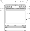
도 1은 발명의 일 실시예에 따른 조리기기를 도시한 사시도이다.
도 2는 도 1에 도시된 조리기기의 정면도이다.
도 3은 도 1에 도시된 조리기기의 내부 구성을 보여주는 측단면도이다.
도 4는 도 3에 도시된 캐비티와 브로일 버너 및 배기덕트를 분리하여 도시한 분해 사시도이다.
도 5는 도 4에 도시된 캐비티와 브로일 버너 및 배기덕트의 결합 상태를 보여주는 사시도이다.
도 6은 도 5에 도시된 캐비티와 브로일 버너 및 배기덕트의 결합 상태를 보여주는 측단면도이다.
도 7은 도 5에 도시된 캐비티 상부면 및 차단부를 분리하여 도시한 사시도이다.
도 8은 도 5의 "Ⅷ-Ⅷ" 선에 따른 단면도이다.
도 9는 도 5의 "Ⅸ-Ⅸ" 선에 따른 단면도이다.
도 10은 도 8에 도시된 배기덕트 내부에서의 물 흐름 상태를 보여주는 도면이다.
도 11은 도 9에 도시된 배기덕트 내부에서의 물 흐름 상태를 보여주는 도면이다.
도 12는 본 발명의 다른 실시예에 따른 차단부의 구성을 보여주는 도면이다.1 is a perspective view illustrating a cooking appliance according to an embodiment of the present invention.
FIG. 2 is a front view of the cooking appliance shown in FIG. 1 .
FIG. 3 is a side cross-sectional view showing an internal configuration of the cooking appliance shown in FIG. 1 .
4 is an exploded perspective view showing the cavity shown in FIG. 3, the broil burner, and the exhaust duct separated.
5 is a perspective view showing a coupling state of the cavity shown in FIG. 4, the broil burner, and the exhaust duct.
FIG. 6 is a side cross-sectional view showing the coupling state of the cavity shown in FIG. 5, the broil burner, and the exhaust duct.
FIG. 7 is a perspective view showing the cavity upper surface and the blocking part shown in FIG. 5 separated.
8 is a cross-sectional view taken along line “VIII-VIII” of FIG. 5 .
9 is a cross-sectional view taken along the line “IX-IX” of FIG. 5 .
FIG. 10 is a view showing a state of water flow in the exhaust duct shown in FIG. 8 .
11 is a view showing a state of water flow in the exhaust duct shown in FIG. 9 .
12 is a view showing the configuration of a blocking unit according to another embodiment of the present invention.
전술한 목적, 특징 및 장점은 첨부된 도면을 참조하여 상세하게 후술되며, 이에 따라 본 발명이 속하는 기술분야에서 통상의 지식을 가진 자가 본 발명의 기술적 사상을 용이하게 실시할 수 있을 것이다. 본 발명을 설명함에 있어서 본 발명과 관련된 공지 기술에 대한 구체적인 설명이 본 발명의 요지를 불필요하게 흐릴 수 있다고 판단되는 경우에는 상세한 설명을 생략한다. 이하, 첨부된 도면을 참조하여 본 발명에 따른 바람직한 실시예를 상세히 설명하기로 한다. 도면에서 동일한 참조부호는 동일 또는 유사한 구성요소를 가리키는 것으로 사용된다.The above-described objects, features and advantages will be described below in detail with reference to the accompanying drawings, and accordingly, those skilled in the art to which the present invention pertains will be able to easily implement the technical idea of the present invention. In describing the present invention, if it is determined that a detailed description of a known technology related to the present invention may unnecessarily obscure the gist of the present invention, the detailed description will be omitted. Hereinafter, preferred embodiments according to the present invention will be described in detail with reference to the accompanying drawings. In the drawings, the same reference numerals are used to indicate the same or similar components.
비록 제1, 제2 등이 다양한 구성요소들을 서술하기 위해서 사용되나, 이들 구성요소들은 이들 용어에 의해 제한되지 않음은 물론이다. 이들 용어들은 단지 하나의 구성요소를 다른 구성요소와 구별하기 위하여 사용하는 것으로, 특별히 반대되는 기재가 없는 한, 제1 구성요소는 제2 구성요소일 수도 있음은 물론이다.Although the first, second, etc. are used to describe various elements, these elements are not limited by these terms, of course. These terms are only used to distinguish one component from other components, and unless otherwise stated, the first component may be the second component, of course.
본 발명은 이하에서 개시되는 실시 예에 한정되는 것이 아니라 다양한 변경을 가할 수 있고 서로 다른 다양한 형태로 구현될 수 있다. 단지 본 실시 예는 본 발명의 개시가 완전하도록 하며 통상의 지식을 가진 자에게 발명의 범주를 완전하게 알려주기 위하여 제공되는 것이다. 따라서 본 발명은 이하에서 개시되는 실시예에 한정되는 것이 아니라, 어느 하나의 실시예의 구성과 다른 실시예의 구성을 서로 치환하거나 부가하는 것은 물론 본 발명의 기술적 사상과 범위에 포함되는 모든 변경, 균등물 내지 대체물을 포함하는 것으로 이해되어야 한다. The present invention is not limited to the embodiments disclosed below, and various changes may be made and may be implemented in various different forms. Only this embodiment is provided so as to complete the disclosure of the present invention and to fully inform those of ordinary skill in the scope of the invention. Therefore, the present invention is not limited to the embodiments disclosed below, and all changes and equivalents included in the technical spirit and scope of the present invention as well as substituting or adding the configuration of any one embodiment and the configuration of other embodiments to each other or substitutes.
첨부된 도면은 본 명세서에 개시된 실시 예를 쉽게 이해할 수 있도록 하기 위한 것일 뿐, 첨부된 도면에 의해 본 명세서에 개시된 기술적 사상이 제한되지 않으며, 본 발명의 사상 및 기술 범위에 포함되는 모든 변경, 균등물 내지 대체물을 포함하는 것으로 이해되어야 한다. 도면에서 구성요소들은 이해의 편의 등을 고려하여 크기나 두께가 과장되게 크거나 작게 표현될 수 있으나, 이로 인해 본 발명의 보호범위가 제한적으로 해석되어서는 아니 될 것이다.The accompanying drawings are only for easy understanding of the embodiments disclosed in the present specification, and the technical spirit disclosed in the present specification is not limited by the accompanying drawings, and all changes and equivalents included in the spirit and scope of the present invention It should be understood to include water or substitutes. In the drawings, in consideration of the convenience of understanding, the size or thickness may be exaggeratedly large or small, but the protection scope of the present invention should not be construed as being limited thereto.
본 명세서에서 사용한 용어는 단지 특정한 구현예나 실시예를 설명하기 위해 사용되는 것으로, 본 발명을 한정하려는 의도가 아니다. 그리고 단수의 표현은, 문맥상 명백하게 다르게 뜻하지 않는 한, 복수의 표현을 포함한다. 명세서에서 ~포함하다, ~이루어진다 등의 용어는 명세서 상에 기재된 특징, 숫자, 단계, 동작, 구성요소, 부품 또는 이들을 조합한 것이 존재함을 지정하려는 것이다. 즉 명세서에서 ~포함하다, ~이루어진다 등의 용어는. 하나 또는 그 이상의 다른 특징들이나 숫자, 단계, 동작, 구성요소, 부품 또는 이들이 조합한 것들의 존재 또는 부가 가능성을 미리 배제하지 않는 것으로 이해되어야 한다.The terms used herein are used only to describe specific embodiments or examples, and are not intended to limit the present invention. And singular expressions include plural expressions unless the context clearly dictates otherwise. In the specification, terms such as includes, consists of, etc. are intended to designate that the features, numbers, steps, operations, components, parts, or combinations thereof described in the specification exist. That is, in the specification, terms such as include and consist of. It should be understood that this does not preclude the possibility of addition or existence of one or more other features or numbers, steps, operations, components, parts, or combinations thereof.
제1, 제2 등과 같이 서수를 포함하는 용어는 다양한 구성요소들을 설명하는데 사용될 수 있지만, 상기 구성요소들은 상기 용어들에 의해 한정되지는 않는다. 상기 용어들은 하나의 구성요소를 다른 구성요소로부터 구별하는 목적으로만 사용된다.Terms including ordinal numbers such as first, second, etc. may be used to describe various elements, but the elements are not limited by the terms. The above terms are used only for the purpose of distinguishing one component from another.
어떤 구성요소가 다른 구성요소에 "연결되어" 있다거나 "접속되어" 있다고 언급된 때에는, 그 다른 구성요소에 직접적으로 연결되어 있거나 또는 접속되어 있을 수도 있지만, 중간에 다른 구성요소가 존재할 수도 있다고 이해되어야 할 것이다. 반면에, 어떤 구성요소가 다른 구성요소에 "직접 연결되어" 있다거나 "직접 접속되어" 있다고 언급된 때에는, 중간에 다른 구성요소가 존재하지 않는 것으로 이해되어야 할 것이다.When a component is referred to as being “connected” or “connected” to another component, it may be directly connected or connected to the other component, but it is understood that other components may exist in between. it should be On the other hand, when it is said that a certain element is "directly connected" or "directly connected" to another element, it should be understood that the other element does not exist in the middle.
어떤 구성요소가 다른 구성요소의 "상부에 있다"거나 "하부에 있다"고 언급된 때에는, 그 다른 구성요소의 바로 위에 배치되어 있는 것뿐만 아니라 중간에 다른 구성요소가 존재할 수도 있다고 이해되어야 할 것이다.When an element is referred to as "over" or "below" another element, it should be understood that other elements may be present in the middle as well as disposed directly on the other element. .
다르게 정의되지 않는 한, 기술적이거나 과학적인 용어를 포함해서 여기서 사용되는 모든 용어들은 본 발명이 속하는 기술 분야에서 통상의 지식을 가진 자에 의해 일반적으로 이해되는 것과 동일한 의미를 가지고 있다. 일반적으로 사용되는 사전에 정의되어 있는 것과 같은 용어들은 관련 기술의 문맥 상 가지는 의미와 일치하는 의미를 가지는 것으로 해석되어야 하며, 본 출원에서 명백하게 정의하지 않는 한, 이상적이거나 과도하게 형식적인 의미로 해석되지 않는다.Unless defined otherwise, all terms used herein, including technical or scientific terms, have the same meaning as commonly understood by one of ordinary skill in the art to which this invention belongs. Terms such as those defined in a commonly used dictionary should be interpreted as having a meaning consistent with the meaning in the context of the related art, and should not be interpreted in an ideal or excessively formal meaning unless explicitly defined in the present application. does not
조리기기가 바닥(floor)에 놓인 상태에서, 조리기기의 중심을 기준으로 도어가 설치된 방향을 전방으로 정의한다. 따라서 도어를 열고 조리기기 내부로 진입하는 방향은 후방이 된다. 편의상 이렇게 전방과 후방을 향하는 방향을 제1방향이라 할 수 있다. 그러면, 전방은 제1방향의 일방, 후방은 제1방향의 타방이라 할 수 있다.In a state in which the cooking appliance is placed on the floor, a direction in which the door is installed based on the center of the cooking appliance is defined forward. Therefore, the direction of opening the door and entering the cooking appliance is the rear. For convenience, this direction toward the front and rear may be referred to as a first direction. Then, the front can be said to be one side in the first direction, and the rear can be said to be the other side in the first direction.
또한 중력 방향을 하방, 중력 방향의 반대 방향을 상방으로 정의할 수 있을 것이다.Also, the direction of gravity may be defined as downward, and the direction opposite to the direction of gravity may be defined as upward.
그리고, 조리기기의 전후방향과 직교하는 수평방향, 즉 조리기기의 도어 앞에서 조리기기를 바라볼 때 조리기기의 폭방향을 좌우방향이라 할 수 있다. 편의상 좌우방향을 제2방향이라 할 수 있다. 그러면, 우측은 제2방향의 일방, 좌측은 제2방향의 타방이라 할 수 있다.In addition, the horizontal direction orthogonal to the front-rear direction of the cooking appliance, that is, the width direction of the cooking appliance when looking at the cooking appliance from the front of the door of the cooking appliance, may be referred to as a left-right direction. For convenience, the left-right direction may be referred to as a second direction. Then, the right side may be said to be one side of the second direction, and the left side may be referred to as the other side of the second direction.
또한 상기 조리기기의 폭방향을 측방향이라 할 수도 있다. 그러면 우측은 측방향의 일측, 좌측은 측방향의 타측이라 할 수 있다.In addition, the width direction of the cooking appliance may be referred to as a lateral direction. Then, the right side can be said to be one side in the lateral direction, and the left side can be said to be the other side in the lateral direction.
그리고, 상술한 상하방향을 제3방향이라 할 수 있다. 그러면, 상방은 제3방향의 일방, 하방은 제3방향의 타방이라 할 수 있다.In addition, the above-described vertical direction may be referred to as a third direction. Then, the upper side can be said to be one side in the third direction, and the lower side can be said to be the other side in the third direction.
또한 상술한 상하방향을 세로방향이라 할 수 있다. 그러면 전후방향과 좌우방향, 즉 제1방향과 제2방향을 포함하여 가로방향이라 할 수 있다.In addition, the above-described vertical direction may be referred to as a vertical direction. Then, the front-rear direction and the left-right direction, that is, the first direction and the second direction can be referred to as a horizontal direction.
명세서 전체에서, "A 및/또는 B" 라고 할 때, 이는 특별한 반대되는 기재가 없는 한, A, B 또는 A 및 B 를 의미하며, "C 내지 D" 라고 할 때, 이는 특별한 반대되는 기재가 없는 한, C 이상이고 D 이하인 것을 의미한다Throughout the specification, when “A and/or B” is used, it means A, B or A and B, unless specifically stated to the contrary, and when “C to D” is used, it means that there is no specific contrary description. Unless otherwise specified, it means that it is greater than or equal to C and less than or equal to D.
[조리기기의 전반적인 구조][Overall structure of cooking equipment]
도 1은 본 발명의 일 실시예에 따른 조리기기를 도시한 사시도이고, 도 2는 도 1에 도시된 조리기기를 도시한 정면도이며, 도 3은 도 1에 도시된 조리기기의 내부 구성을 보여주는 측단면도이다.1 is a perspective view showing a cooking appliance according to an embodiment of the present invention, FIG. 2 is a front view showing the cooking appliance shown in FIG. 1, and FIG. 3 is an internal configuration of the cooking appliance shown in FIG. It is a side cross-sectional view.
도 1 내지 도 4를 참조하면, 본 발명의 일 실시예에 따른 조리기기는 쿡탑부(20)와 오븐부(30)를 포함할 수 있다.1 to 4 , a cooking appliance according to an embodiment of the present invention may include a
조리기기(1)는 본체(10)에 의해 외관이 형성될 수 있다. 본체(10)는, 대략 직육면체 형상을 포함하는 형태로 마련될 수 있으며, 그 내부공간에 설치되는 다수의 부품을 보호하기 위하여 소정의 강도를 갖는 재질로 형성될 수 있다.The
상기 본체(10)는, 본체(10)의 골격을 형성하는 캐비티(11), 및 캐비티(11)의 전방에 배치되어 본체(10)의 전면을 형성하는 프런트 패널(13)을 포함하여 이루어질 수 있다. 캐비티(11)의 내부에는 조리실(31)이 형성되며, 프런트 패널(13)의 내부에는 조리실(31)을 전방으로 개방하는 개구부가 형성될 수 있다.The
본체(10)의 상부에는, 쿡탑부(20)가 배치될 수 있다. 쿡탑부(20)는, 개방된 공간 즉, 상측에 놓이는 음식물 또는 음식물이 담긴 용기를 가열하여 음식물을 요리할 수 있게 마련될 수 있다. 쿡탑부(20)에는, 쿡탑부(20)의 상면 외관을 형성하면서 본체(10)의 상단을 폐쇄하는 탑플레이트(21)가 제공될 수 있다.A
쿡탑부(20)에는, 요리하고자 하는 음식물 또는 음식물이 담긴 용기를 가열하기 위한 적어도 하나 이상의 쿡탑가열부(22)가 배치될 수 있다.At least one
일례로서, 쿡탑가열부(22)는, 가스연료를 이용하는 가열장치로 구비될 수 있다. 다른 예로서, 쿡탑가열부는 전기를 이용하는 히터나 유도가열부로 구비될 수도 있다. 이처럼, 이용되는 열원의 종류에 따라 쿡탑가열부(22)의 구조는 변경될 수 있다.As an example, the
그리고 쿡탑부(20)의 하부에는, 오븐부(30)가 배치될 수 있다. 오븐부(30)의 내부공간에는, 음식물이 요리되는 공간을 제공하는 조리실(31)이 마련될 수 있다.In addition, the
캐비티(11)는 전면이 개방된 육면체의 형태로 형성될 수 있으며, 조리실(31)은 이러한 캐비티(11)의 내부에 형성될 수 있다. 즉 조리실(31)은, 캐비티(11) 내부에 배치된 대략 육면체 형상의 공간으로 형성될 수 있으며, 전방으로 개방된 공간으로 형성될 수 있다.The
이러한 조리실(31)이 차폐된 상태에서, 조리실(31) 내부가 가열되면서 음식물 조리가 이루어질 수 있다. 즉 오븐부(30)에서는, 조리실(31)이 실질적으로 음식물이 요리되는 공간이다.In a state in which the
조리기기에는, 조리실(31)을 가열하는 가열부가 마련될 수 있다. 이러한 가열부는, 가스연료를 이용하는 가열장치로 구비될 수 있다. 다른 예로서, 쿡탑가열부는 전기를 이용하는 히터로 구비될 수도 있다. 이처럼, 이용되는 열원의 종류에 따라 가열부의 구조는 변경될 수 있다.A heating unit for heating the
본 실시예에서는, 가열부가 가스연료를 이용하는 가열장치로 구비되는 것으로 예시된다. 이에 따르면, 조리실(31)의 상측에는 상기 조리실(31)의 내부공간을 상측에서 가열하는 브로일 버너(35)가 제공될 수 있고, 조리실(31)의 하측에도 조리실(31)의 내부공간을 하측에서 가열하는 베이커 버너 형태의 버너가 더 제공될 수도 있다.In this embodiment, it is exemplified that the heating unit is provided as a heating device using gas fuel. According to this, a
또한 조리실(31)의 후측에는, 뜨거운 공기를 대류시켜 조리실(31)의 내부공간을 가열하는 컨벡션부(37)가 더 제공될 수 있다.In addition, a
컨벡션부(37)는, 조리실(31) 내부공간의 공기를 강제로 유동시킨다. 즉 컨벡션부(37)는, 조리실(31) 내부공간의 공기를 흡입하여 가열한 후, 조리실(31)의 내부 공간으로 배출시키면서 공기를 유동시킴으로써, 조리실(31)의 내부공간이 가열되도록 하고, 이로써 조리실(31)의 내부공간에 위치하는 음식물이 균일하게 가열되도록 한다.The
오븐부(30)에는, 조리실(31)을 선택적으로 개폐하는 도어(32)가 회동 가능하게 제공될 수 있다. 일례로서, 도어(32)는 그 하단을 중심으로 상단이 상하로 회동하는 풀-다운(Pull-down) 방식으로 조리실(31)을 개폐하는 형태로 제공될 수 있다.A
이러한 도어(32)는, 전체적으로 소정의 두께를 가지는 육면체 형태로 형성될 수 있다. 이러한 도어(32)의 전방에는, 손잡이(33)가 배치될 수 있다. 손잡이(33)는, 사용자가 도어(32)를 회동시키고자 할 때 파지할 수 있게 마련된다. 사용자는, 손잡이(33)를 이용하여 도어(32)를 용이하게 회동시킬 수 있다.The
조리기기의 전면 상부, 즉 캐비티(11)의 상부 전면에는 컨트롤패널(50)이 구비될 수 있다. 컨트롤패널(50)은, 조리기기 전면 외관의 일부를 형성할 수 있다. 이러한 컨트롤패널(50)에는, 조리기기의 동작을 조절하기 위한 노브(51) 및 조리기기의 작동 상태를 표시하는 디스플레이(52) 등이 구비될 수 있다.The
예컨대, 컨트롤패널(50)은 도어(32)의 상부 및 쿡탑부(20)의 전방에 배치되는 컨트롤패널 커버(50a)에 입력부(51) 및 디스플레이(52)가 설치된 형태로 구비될 수 있다.For example, the
입력부(52)에는 다수의 조작스위치가 마련되며, 이를 통해 사용자가 직접 조작신호를 입력할 수 있다. 이때 조작스위치는 회전 조작 가능한 노브(Knob) 형태로 마련될 수도 있고, 누름 조작이나 터치 조작 가능한 버튼 또는 패널 형태로 마련될 수도 있다.The
또한 컨트롤패널(50)에는, 조리기기의 동작 정보 또는 음식물의 요리 정보 등을 제공하는 디스플레이(52)가 더 마련될 수 있다. 사용자는, 디스플레이(52)를 통해 조리기기에 관한 다양한 정보를 확인할 수 있다.In addition, the
다른 예로서, 디스플레이(52)가 터치 조작 가능한 터치 패널 형태로 마련되고, 이로써 하나의 터치 패널에 입력부(51)와 디스플레이(52)가 함께 구성될 수도 있다.As another example, the
한편, 조리실(31)의 후방에는, 배후공간(34)이 마련될 수 있다. 배후공간(34)은, 캐비티(11)의 후방에 배치되며, 조리실(31)과 배후공간(34) 사이를 전후방향으로 구획하는 구획면(30a)에 의해 조리실(31)과 구획된 공간이다. 배후공간(34)의 전방 경계면은 구획면(30a)에 의해 정의되고, 배후공간(34)의 후방 경계면은 캐비티(11)의 후방에 설치되는 리어 커버(15)에 의해 정의될 수 있다.Meanwhile, a
캐비티(11)의 외부에는, 상부공간(40)이 마련될 수 있다. 상부공간(40)은, 캐비티(11)의 상부 및 컨트롤패널(50)의 배후에 배치될 수 있다. 상부공간(40)의 내부에는, 쿡탑가열부(22)를 구성하기 위한 부품이나 전장부품들이 설치되기 위한 공간이 형성될 수 있다.An
상부공간(40)의 전면은, 프런트 패널(13)에 의해 차폐될 수 있다. 프런트 패널(13)은, 캐비티(11)와 도어(32) 사이에 배치될 수 있다. 이러한 프런트 패널(13)은, 적어도 일부분이 상부공간(40)의 전방을 가로막게 배치될 수 있다. 예컨대, 조리실(31)의 상부에 배치된 프런트 패널(13)의 상부 영역이 상부공간(40)의 전면을 차폐할 수 있다.The front surface of the
프런트 패널(13)에는, 흡기구(14)가 마련될 수 있다. 흡기구(14)는, 프런트 패널(13)에 전후방향으로 관통되게 형성될 수 있다. 이러한 흡기구(14)는, 상부공간(40) 외부의 공기가 상부공간(40) 내부로 유입되기 위한 통로를 프런트 패널(13) 상에 형성할 수 있다.The
[쿡탑부의 구조][Structure of the cooktop part]
쿡탑부(20)는, 상술한 바와 같이, 오븐부(30)의 상부에 배치되며, 탑플레이트(21) 및 쿡탑가열부(22)를 포함할 수 있다.As described above, the
탑플레이트(21)는 캐비티(11)의 상부에 배치되며, 상부공간(40)은 탑플레이트(21)와 캐비티(11) 사이에 배치될 수 있다. 즉 탑플레이트(21)는, 탑플레이트(21)와 캐비티(11) 사이에 상부공간(40)이 형성되도록, 캐비티(11)의 상부를 덮을 수 있다.The
캐비티(11)의 외부에는, 상부공간(40)이 마련될 수 있다. 상부공간(40)은, 캐비티(11)와 탑플레이트(21) 사이에 배치되되, 컨트롤패널(50)의 배후에 배치될 수 있다. 상부공간(40)의 내부에는, 쿡탑가열부(22)를 구성하기 위한 부품이나 전장부품들이 설치되기 위한 공간이 형성될 수 있다.An
예컨대, 쿡탑가열부(22)가 가스연료를 이용하는 가열장치로 구비되는 경우, 상부공간(40)에는 가스를 연소시키는 버너, 버너에 가스를 공급하기 위한 공급관, 버너로의 가스 공급을 조절하기 위한 밸브 등이 배치될 수 있다.For example, when the
다른 예로서, 쿡탑가열부(22)가 전기를 이용하는 가열장치로 구비되는 경우, 상부공간(40)에는 히터나 유도가열부, 그리고 이들을 구동시키기 위한 각종 전장부품들이 배치될 수 있다.As another example, when the
본체(10)는, 사이드 패널(17)을 더 포함할 수 있다. 사이드 패널(17)은, 캐비티(11)의 양측부에 각각 배치될 수 있다. 각각의 사이드 패널(17)은, 캐비티(11)의 외측에서 캐비티(11)의 측부를 덮으며 본체(10)의 측방 외관을 형성할 수 있다.The
각각의 사이드 패널(17)은, 캐비티(11)의 측부를 덮으며 캐비티(11)의 상부로 연장되게 형성될 수 있다. 이에 따라 상부공간(40)의 측방 경계면은, 캐비티(11)의 양측에서 상부로 연장되는 한 쌍의 사이드 패널(17)에 의해 정의될 수 있다.Each
캐비티(11)의 후방에는 리어 커버(15)가 배치될 수 있다. 리어 커버(15)는, 캐비티(11)의 후방을 덮으며 본체(10)의 후방 외관을 형성할 수 있다. 이러한 리어 커버(15)는, 캐비티(11)의 후방에 마련되는 배후공간(34)의 후방 경계면을 정의할 수 있다.A
또한 리어 커버(15)에는 환기구(16)가 마련될 수 있다. 환기구(16)는, 리어 커버(15)에 전후방향으로 관통되게 형성될 수 있으며, 배후공간(34) 내부에 배치된 전장부품의 냉각을 위한 공기 출입 통로를 리어 커버(15) 상에 형성할 수 있다.In addition, a
상기 리어 커버(15)는, 캐비티(11)의 후방을 덮으며 캐비티(11)의 상부로 연장되게 형성될 수 있다. 이에 따라 상부공간(40)의 후방 경계면은, 캐비티(11)의 후방에서 상부로 연장되는 리어 커버(15)에 의해 정의될 수 있다.The
즉 상부공간(40)의 전후방 및 양측방은 프런트 패널(13)과 리어 커버(15) 및 한 쌍의 사이드 패널(17)에 의해 둘러싸이며, 탑플레이트(21)는 이러한 상부공간(40)의 상부를 덮는다.That is, the front and rear and both sides of the
이러한 탑플레이트(21)는, 프런트 패널(13)과 리어 커버(15) 및 한 쌍의 사이드 패널(17)의 상부에 배치되며, 프런트 패널(13)과 리어 커버(15) 및 한 쌍의 사이드 패널(17)과 각각 결합될 수 있다. 즉 탑플레이트(21)는, 프런트 패널(13)과 리어 커버(15) 및 한 쌍의 사이드 패널(17)과 각각 결합되면서, 상부공간(40)의 상부에 고정될 수 있다.The
배기덕트(41)는, 조리실(31) 내부에서 음식물을 조리하는 과정에서 발생되는 연소가스를 조리기기 외부로 배출하기 위해 마련될 수 있다.The
이러한 배기덕트(41)는, 그 하단부가 조리실(31)의 상부와 연결되고 상단부가 조리기기(1)의 후면 상부 측에 배치되도록 마련될 수 있다. 예컨대, 배기덕트(41)의 상단부는 쿡탑부(20)의 후방에 배치될 수 있다. 본 실시예에서는, 배기덕트(41)의 상단부가 탑플레이트(21)를 관통하여 쿡탑부(20)의 상부로 개방되는 것으로 예시된다.The
이에 따르면, 조리실(31)에서 발생되는 연소가스는 조리실(31)의 상부에 연결된 배기덕트(41)로 유입되어 상부로 유동되며, 배기덕트(41)의 상단부를 통해 조리기기(1)의 후면에서 상부방향으로 배출될 수 있다.According to this, the combustion gas generated in the
상기 제1배기구(23)의 상부에는 벤트그릴(60)이 배치될 수 있다. 벤트그릴(60)은, 탑플레이트(21)의 상부에서 제1배기구(23)를 덮을 수 있게 마련된다.A
벤트그릴(60)은, 제1배기구(23)가 배치된 영역을 포함한 탑플레이트(21)의 후방 일부 영역을 상부에서 덮을 수 있게 마련될 수 있다. 이러한 벤트그릴(60)은, 캐비티(31)의 후면과 리어 커버(15) 사이의 공간인 배후공간(34)이 상부로 개방된 부분, 즉 구획면(30a)과 리어 커버(15) 사이에 형성된 상단개구 또한 상부에서 덮을 수 있다. 이에 따라 벤트그릴(60)의 내부에는, 벤트그릴(60)과 탑플레이트(21) 및 리어 커버(15)로 둘러싸인 공간이 형성될 수 있다.The
본 실시예에서는, 벤트그릴(60)이 하부가 개방된 육면체 형상으로 형성되는 것으로 예시된다. 이러한 벤트그릴(60)에는, 배기덕트(41)를 통해 배출되는 연소가스를 통과시키기 위한 적어도 하나의 벤트홀(61)이 마련될 수 있다. 이러한 벤트홀(61)은, 벤트그릴(60)의 상부면에 상하방향으로 관통되게 형성될 수 있다.In this embodiment, it is illustrated that the
[브로일 버너 및 그 주변 구조][Broil burner and its surrounding structure]
도 4는 도 3에 도시된 캐비티와 브로일 버너 및 배기덕트를 분리하여 도시한 분해 사시도이고, 도 5는 도 4에 도시된 캐비티와 브로일 버너 및 배기덕트의 결합 상태를 보여주는 사시도이며, 도 6은 도 5에 도시된 캐비티와 브로일 버너 및 배기덕트의 결합 상태를 보여주는 측단면도이다.4 is an exploded perspective view showing the cavity, the broil burner, and the exhaust duct shown in FIG. 3 separated, and FIG. 5 is a perspective view showing the coupling state of the cavity, the broil burner, and the exhaust duct shown in FIG. 4, FIG. 6 is a side cross-sectional view showing the coupling state of the cavity shown in FIG. 5, the broil burner, and the exhaust duct.
도 3 내지 도 6을 참조하면, 조리실(31)의 내부에는 브로일 버너(35)가 구비될 수 있다. 이러한 브로일 버너(35)는, 조리실(31)의 상부에서 조리실(31) 내부를 가열할 수 있다.3 to 6 , a
본 실시예에서, 브로일 버너(35)는 버너본체(351)와 믹싱튜브(353) 및 점화장치(355)를 포함하는 것으로 예시된다.In this embodiment, the
버너본체(351)는, 조리실(31)의 상측에 구비된다. 버너본체(351)는, 조리실(31)의 상면에 결합되며, 본체(10)의 전후방향(이하 "전후방향"이라 한다)으로 연장되는 길이를 갖는 직선의 파이프 형태로 형성될 수 있다.The
이러한 버너본체(351)의 내부에는, 혼합가스가 공급되는 유로가 전후방향으로 연장되는 형태로 형성될 수 있다. 그리고 버너본체(351)의 측부에는 염공이 관통되게 형성될 수 있으며, 이러한 염공은 버너본체(351) 내부의 가스가 버너본체(351) 외부로 배출되는 통로를 형성한다.In the inside of the
상기 버너본체(351)의 측부에는, 복수 개의 염공이 버너본체(351)의 길이방향을 따라 각각 소정 간격 이격되게 배치될 수 있다. 이로써 버너본체(351)에는 버너본체(351)의 길이방향을 따라 복수 개의 가스 배출 통로가 마련될 수 있게 된다.On the side of the
본 실시예에 따르면, 버너본체(351)는 후술할 믹싱튜브(353)를 통해 공기와 혼합된 가스, 즉 혼합가스를 공급받으며, 이와 같이 버너본체(351) 내부의 유로로 공급된 혼합가스는 염공을 통해 버너본체(351) 외부로 배출되며 연소됨으로써 버너본체(351)의 외부에 화염을 발생시킬 수 있다.According to this embodiment, the
믹싱튜브(353)는, 일측이 버너본체(351)에 연결되는 직선의 파이프 형태로 형성될 수 있다. 본 실시예에서는, 버너본체(351)가 전후방향으로 연장되는 직선의 파이프 형태로 형성되고, 믹싱튜브(353)가 본체(10)의 좌우방향(이하 "좌우방향"이라 한다)으로 연장되는 직선의 파이프 형태로 형성되며, 버너본체(351)와 믹싱튜브(353)가 "ㄱ" 형상을 이루며 연결되는 것으로 예시된다.The mixing
믹싱튜브(353)의 내부에는, 가스와 공기가 혼합되는 믹싱유로가 형성된다. 믹싱유로는, 중공의 파이프 형태로 형성된 믹싱튜브(353)의 내부에 형성되며, 믹싱튜브(353)의 내부로 각각 유입된 가스와 공기가 믹싱튜브(353)의 내부에서 버너본체(351) 측으로 유동하는 동안 이러한 가스와 공기의 혼합이 이루어질 수 있도록 하는 공간을 제공한다.A mixing passage in which gas and air are mixed is formed in the mixing
아울러 브로일 버너(35)에는, 리플렉터(355)가 설치될 수 있다. 리플렉터(355)는 브로일 버너(35)에서 혼합가스가 연소되어 발생되는 화염 및 열을 하방, 즉 상기 조리실(31)의 내부의 조리물을 향하여 반사시키는 역할을 할 수 있다.In addition, a
또한 리플렉터(355)는, 브로일 버너(35)에서 혼합가스가 연소되는 과정에서 발생되는 연소가스를 리플렉터(355)의 상방, 즉 조리실(31)의 천장면과 리플렉터(355)의 상부면 사이의 공간으로 유동시키는 역할을 할 수 있다.In addition, the
캐비티(11)의 상부면에는 배기구(12)가 상하방향으로 관통되게 형성될 수 있다. 배기덕트(41)는 이 배기구(12)를 통해 조리실 내부와 연결될 수 있다. 배기덕트(41)는, 조리실(31) 내부에서 음식물을 조리하는 과정에서 발생되는 연소가스를 조리기기(1) 외부로 배출하기 위해 마련될 수 있다.An
이러한 배기덕트(41)는, 그 하단부가 조리실(31)의 상부와 연결되고 상단부가 조리기기(1)의 후면 상부 측에 배치되도록 마련될 수 있다. 예컨대, 배기덕트(41)의 상단부는 쿡탑부(20)의 후방에 배치될 수 있다.The
본 실시예에서는, 배기덕트(41)가 제1덕트부(411)와 제2덕트부(415)를 포함하는 것으로 예시된다. 제1덕트부(411)와 제2덕트부(415)는 상하방향으로 연결되게 배치될 수 있으며, 이들 중 하부에는 제1덕트부(411)가 배치되고, 상부에는 제2덕트부(415)가 배치될 수 있다.In this embodiment, the
제1덕트부(411)는, 배기구(12)와 인접하게 배치된다. 제1덕트부(411)는, 캐비티(11)의 일측면, 즉 캐비티(11)의 상부면과 제2덕트부(415) 사이에 배치될 수 있다. 이러한 제1덕트부(411)의 내부에는, 배기구(12)와 연결되는 제1배기유로(411a)가 형성될 수 있다.The
제1덕트부(411)는, 캐비티(11)의 상부면과 제2덕트부(415) 사이를 연결하는 복수개의 측벽을 포함할 수 있다. 제1덕트부(411)에서는, 상기 복수개의 측벽이 전후좌우방향으로 제1배기유로(411a)를 둘러싸며 서로 연결될 수 있다. 예컨대, 제1덕트부(411)는 4개의 측벽이 사각 형상을 이루며 연결되는 형태, 바꾸어 표현하면 4개의 측벽을 포함하며 상단과 하단이 개방된 육면체 형태로 형성될 수 있다.The
아울러 제1덕트부(411)는, 결합부(413)를 더 포함할 수 있다. 결합부(413)는, 배기덕트(41)와 캐비티(11) 간의 결합을 위해 마련되는 것이다. 이러한 결합부(413)는, 복수개의 측벽으로부터 돌출되어 캐비티(11)의 일측면, 즉 캐비티(11)의 상부면과 결합될 수 있다.In addition, the
상기 결합부(413)는, 복수개의 측벽 중 어느 하나의 하단으로부터 캐비티(11)의 일측면과 나란한 방향으로 돌출되게 형성될 수 있다. 예컨대, 결합부(413)는 각 측벽의 하단으로부터 각각 돌출되게 형성될 수 있으며, 각각의 결합부(413)는 측벽과 "ㄴ" 형상을 이루도록 측벽의 하단으로부터 돌출되게 형성될 수 있다.The
제2덕트부(415)는, 제1덕트부(411)와 벤트그릴(60) 사이에 배치될 수 있다. 이러한 제2덕트부(415)의 내부에는 제2배기유로(415a)가 형성될 수 있다. 제2배기유로(415a)의 일측은 제1배기유로(411a)와 연결되며, 제2배기유로(415a)의 타측은 배기구(12)의 상부로 개방될 수 있다.The
구체적으로, 제2배기유로(415a)의 하단은 제1배기유로(411a)와 연결되며, 제2배기유로(415a)의 상단은 벤트그릴(60) 측으로 개방될 수 있다. 제1배기유로(411a)와 제2배기유로(415a)는 상하방향으로 연결되며, 이와 같이 연결된 제1배기유로(411a)와 제2배기유로(415a)를 합쳐 배기유로(411a,415a)라고 할 수 있다.Specifically, the lower end of the
제2덕트부(415)는, 배기구(12)보다 후방에 배치될 수 있다. 즉 제1덕트부(411)의 하단에 비해 제2덕트부(415)가 후방에 배치될 수 있다. 이러한 제2덕트부(415)와 배기구(12) 사이를 연결하는 제1덕트부(411)는, 배기구(12)로부터 제2덕트부(415) 측으로 상향 경사지게 연장될 수 있다. 즉 제1덕트부(411)는, 상부로 갈수록 후방으로 치우치도록 경사지게 설치될 수 있다.The
이에 따라 제1덕트부(411)를 형성하는 복수개의 측벽 중 최후방에 배치되는 측벽인 후방측벽(412)은, 상기 복수개의 측벽 중에서 가장 낮은 곳에 위치하는 측벽이 될 수 있다.Accordingly, the
조리실(31)의 천장면과 리플렉터(355)의 상면 사이의 공간으로 유동하는 연소가스는, 캐비티(11)의 상부면에 형성된 배기구(12)를 통해 조리실(31)의 외부로 배출될 수 있다.The combustion gas flowing into the space between the ceiling surface of the
그리고 배기구(12)를 통해 배출된 연소가스는, 배기덕트(41)의 내부에 형성된 배기유로(411a,415a)를 통해 상부로 유동되며, 조리기기(1)의 후방측에서 벤트그릴(60)을 통과하며 상부방향으로 배출될 수 있다.And the combustion gas discharged through the
아울러 브로일 버너(35)에는, 점화장치(357)가 마련될 수 있다. 점화장치(357)는, 염공에서 배출되는 혼합가스를 점화시키는 역할을 한다. 일례로서, 점화장치(357)는 표면에 세라믹이 코팅된 발열체를 포함할 수 있다. 브로일 버너(35)의 염공에서 배출되는 혼합가스의 온도는 점화장치(357)의 발열체에서 발생되는 열에 의해 발화온도까지 상승될 수 있고, 이에 의해 브로일 버너(35)의 점화가 이루어질 수 있다.In addition, the
상기 점화장치(357)는, 조리실(31)의 천장면과 리플렉터(355) 사이에 배치될 수 있다. 좀 더 구체적으로, 점화장치(357)는 배기구(12)의 하부에 배치될 수 있다. 즉 점화장치(357)는, 배기구(12)와 리플렉터(355) 사이에 배치될 수 있다.The
[차단부의 구조][Structure of the breaker]
도 7은 도 5에 도시된 캐비티 상부면 및 차단부를 분리하여 도시한 사시도이고, 도 8은 도 5의 "Ⅷ-Ⅷ" 선에 따른 단면도이며, 도 9는 도 5의 "Ⅸ-Ⅸ" 선에 따른 단면도이다.7 is a perspective view showing the upper surface of the cavity and the blocking part shown in FIG. 5 separately, FIG. 8 is a cross-sectional view taken along the line "VIII-VIII" of FIG. 5, and FIG. 9 is the line "IX-IX" of FIG. It is a cross-sectional view according to
도 6 내지 도 8을 참조하면, 배기덕트(41)의 내부에는, 차단부(100)가 구비될 수 있다. 차단부(100)는, 배기덕트(41) 내부의 배기유로(411a,415a)에서 배기구(12)를 향해 흘러내리는 물의 이동 경로 중 적어도 일부를 가로막도록 마련된다.6 to 8 , a blocking
차단부(100)는, 배기유로(411a,415a)의 타측과 배기구(12) 사이, 즉 배기유로(411a,415a)의 개방된 상단과 배기구(12) 사이에 배치될 수 있다. 본 실시예에서는, 차단부(100)가 제1덕트부(411)의 내부에 배치되는 것으로 예시된다. 이러한 차단부(100)는, 제1덕트부(411)를 형성하는 복수개의 측벽 중 최후방에 배치되는 측벽인 후방측벽(412)과 배기구(12) 사이에 배치될 수 있다. 즉 차단부(100)는, 제1덕트부(411)의 내부에서 배기구(12)와 후방측벽(412) 사이에 배치될 수 있다.The blocking
이러한 차단부(100)는, 캐비티(11)의 일측면으로부터 세로방향으로 돌출되게 구비될 수 있다. 본 실시예에서는, 차단부(100)가 캐비티(11)의 상부면의 상부에 마련되되, 수직방향으로 돌출되게 형성되는 것으로 예시된다.The blocking
상기 배기구(12)와 후방측벽(412) 사이는, 캐비티(11)의 일측면, 즉 캐비티(11)의 상부면에 의해 연결될 수 있다. 그리고 차단부(100)는, 캐비티(11)의 상부면으로부터 상측으로 돌출되게 형성될 수 있다. 즉 차단부(100)가 캐비티(11)와 일체로 형성되며, 캐비티(11)의 상부면의 일부분에 의해 차단부(100)가 형성될 수 있다.The
본 실시예에 따르면, 캐비티(11)의 상부면의 일부분이 상하방향으로 타공되어 배기구(12)가 형성될 수 있다. 그리고 차단부(100)는, 배기구(12)를 둘러싸는 캐비티(11)의 테두리 중 일부분이 상부방향으로 연장된 형태로 형성될 수 있다.According to the present embodiment, a portion of the upper surface of the
일례로서, 배기구(12)를 둘러싸는 캐비티(11)의 테두리에는 돌출벽부(110)가 마련될 수 있다. 돌출벽부(110)는, 배기구(12)를 둘러싸는 캐비티(11)의 테두리로부터 상부방향으로 돌출되는 형태로 형성될 수 있다.As an example, the protruding
이러한 돌출벽부(110)는, 배기구(12)를 반경방향 외측에서 둘러싸는 벽면 형태로 형성될 수 있으며, 배기구(12) 및 이를 둘러싸는 캐비티(11)의 테두리로부터 상부방향으로 돌출되는 벽면 형태로 형성될 수 있다.The protruding
예컨대, 돌출벽부(110)는 배기구(12)를 형성하기 위해 캐비티(11)의 상부면을 하부에서 상부로 타공할 때 발생되는 버(Burr) 형태로 형성될 수 있다. 배기구(12)의 주변은, 배기구(12)의 반경방향 외측을 둘러싸는 돌출벽부(110)에 의해 둘러싸일 수 있다.For example, the protruding
차단부(100)는, 상기 돌출벽부(110)와 마찬가지로, 배기구(12)를 둘러싸는 캐비티(11)의 테두리 중 일부분이 상부방향으로 돌출 또는 연장된 형태로 형성될 수 있다. 돌출벽부(110)가 배기구(12) 주변을 완전히 둘러쌀 수 있게 형성되는 것에 비해, 차단부(100)는 돌출벽부(110)처럼 배기구(12) 주변을 완전히 둘러싸는 것은 아니고, 배기구(12)를 둘러싸는 캐비티(11)의 테두리 중 일부분에만 배치될 수 있다.The blocking
또한 본 실시예에서는, 차단부(100)의 높이가 돌출벽부(110)의 높이보다 높은 것으로 예시된다. 즉 차단부(100)는, 돌출벽부(110)보다 상부방향으로 더 돌출되게 형성될 수 있다.Also, in this embodiment, the height of the blocking
차단부(100)는, 배기유로(411a,415a)의 타측과 점화장치(357) 사이에 배치될 수 있다. 본 실시에에서는, 제2배기유로(415a)와 배기구(12) 사이에 차단부(100)가 배치되는 것으로 에시된다. 상부에서 보았을 때, 점화장치(357)는 배기구(12)의 상부로 노출될 수 있으며, 차단부(100)는 배기구(12)와 제2배기유로(415a) 사이에 배치되어 제2배기유로(415a)와 배기구(12) 사이의 통로 중 적어도 일부분을 차단할 수 있다. 이러한 차단부(100)는, 배기유로(411a,415a)에서 점화장치(357)를 향해 흘러내리는 물의 이동 경로를 가로막을 수 잇다.The blocking
차단부(100)는, 점화장치(357)의 후방에 배치될 수 있다. 이러한 차단부(100)는, 배기구(12)의 후방측에 배치됨으로써, 배기구(12)를 통해 캐비티(11)의 상부, 즉 배기유로(411a,415a) 측으로 노출되는 점화장치(357)의 적어도 일부분의 후방에 배치될 수 있다. 즉 차단부(100)는, 점화장치(357) 중 배기구(12)를 통해 캐비티(11)의 상부로 노출되는 부분의 후방에 배치될 수 있다.The blocking
상기 차단부(100)의 좌우방향 폭은. 도 8 및 도 9에 도시된 바와 같이, 배기구(12)의 좌우방향 폭 이하로 설정될 수 있다. 일례로서, 차단부(100)의 좌우방향 폭은 점화장치(357)의 좌우방향 폭과 배기구(12)의 좌우방향 폭 사이로 설정될 수 있다. 좀 더 구체적으로, 차단부(100)의 좌우방향 폭은 점화장치(357)의 좌우방향 폭보다 크고, 배기구(12)의 좌우방향 폭보다 작게 설정될 수 있다.The width in the left and right direction of the blocking
이러한 차단부(100)는, 점화장치(357)보다 좌우방향으로 더 돌출되게 형성될 수 있다. 즉 차단부(100)는, 상부에서 보았을 때, 차단부(100)의 좌우방향 양측 단부가 점화장치(357)보다 좌측 및 우측으로 더 튀어나오는 형태로 형성될 수 있다.The blocking
[차단부의 작용, 효과][Operation and effect of blockers]
도 10은 도 8에 도시된 배기덕트 내부에서의 물 흐름 상태를 보여주는 도면이고, 도 11은 도 9에 도시된 배기덕트 내부에서의 물 흐름 상태를 보여주는 도면이다.FIG. 10 is a view showing a state of water flow in the exhaust duct shown in FIG. 8 , and FIG. 11 is a view showing a state of water flow in the exhaust duct shown in FIG. 9 .
이하, 도 10 및 도 11을 참조하여 차단부가 구비된 본 실시예의 조리기기의 작용, 효과에 대하여 설명한다.Hereinafter, with reference to FIGS. 10 and 11, the operation and effect of the cooking appliance of the present embodiment provided with the blocking unit will be described.
도 10 및 도 11을 참조하면, 차단부(100)는 배기구(12)의 후방측에 배치되어 점화장치(357)의 후방에 배치되되, 점화장치(357)보다 좌우방향으로 더 돌출되게 형성되며, 배기구(12)를 둘러싸는 돌출벽부(110)보다 상부방향으로 더 돌출되게 형성될 수 있다.10 and 11 , the blocking
쿡탑부(20) 등에 대한 물청소가 이루어지거나 쿡탑부(20)에서 조리가 이루어지는 과정에서 끓어 넘친 물로 인해 벤트그릴(60) 주변에 물이 채워졌을 때, 벤트그릴(60)의 배기구(12)를 통해 물이 배기덕트(41)의 내부로 유입될 수 있다. 그리고 이처럼 배기덕트(41)의 내부로 유입된 물은, 배기유로(411a,415a)를 통해 배기구(12) 측으로 흘러내릴 수 있다.When water is cleaned around the
이때 배기덕트(41)의 내부로 유입된 물은, 배기유로(411a,415a) 내부에서 주로 후방측벽(412)을 타고 배기구(12)를 향해 흘러내리게 된다. 이처럼 흘러내리는 물의 흐름 중 적어도 일부분은, 제2배기유로(415a)와 배기구(12) 사이에 배치된 차단부(100)에 의해 가로막히게 된다.At this time, the water introduced into the
상술한 바와 같이, 차단부(100)는 배기구(12)의 후방측에 배치되어 배기유로(411a,415a)와 점화장치(357) 사이를 가로막을 수 있게 마련된다. 이러한 차단부(100)는, 주로 후방측벽(412)을 타고 배기유로(411a,415a) 내부에서 점화장치(357)를 향해 흘러내리는 물의 흐름을 차단할 수 있다.As described above, the blocking
이와 같은 차단부(100)의 작용에 의해, 배기덕트(41)를 타고 흘러내리는 물은 차단부(100)에 막혀 배기구(12) 하부로 흘러내리지 못하고 배기구(12)의 주변으로 퍼지게 된다.By the action of the
배기구(12) 주변은, 돌출벽부(110)에 의해 둘러싸여 있다. 즉 배기구(12) 주변은 차단부(100) 및 돌출벽부(110)에 의해 둘러싸이며, 배기유로(411a,415a)와 배기구(12) 사이를 연결하는 통로는 차단부(100) 및 돌출벽부(110)에 의해 막힌 상태이다.The periphery of the
차단부(100)에 막혀 배기구(12) 하부로 흘러내리지 못하고 배기구(12)의 주변으로 퍼진 물은, 배기구(12)를 둘러싸는 돌출벽부(110)로 인해 배기구(12)의 하부로 흘러내리지 못하고 캐비티(11)의 상부면에서 점점 넓게 퍼진 후, 캐비티(11)의 열에 의해 기화될 수 있다.The water, which is blocked by the blocking
즉 차단부(100)에 막혀 배기구(12)의 주변으로 퍼진 물은, 결국 배기구(12)를 통해 점화장치(357) 측으로 흘러내리지 못하고 캐비티(11)의 상부면에서 퍼져 나가다가 브로일 버너(35) 등과 같은 가열부의 동작에 의해 가열된 캐비티(11)의 열에 의해 기화되는 형태로 제거될 수 있다.That is, the water blocked by the blocking
상기 차단부(100)는, 돌출벽부(110)보다 상부방향으로 더 돌출되게 형성되는데, 배기구(12) 주변을 둘러싸는 돌출벽부(110)와 달리, 배기구(12) 주변 전체를 둘러싸지는 않고, 점화장치(357)로의 물의 이동을 차단할 수 있을 정도의 폭으로 형성된다. 즉 차단부(100)는 배기구(12) 주변 전체를 둘러싸는 형태로 형성되지 않는다.The blocking
차단부(100)는 배기유로(411a,415a) 내부에 돌출되는 구조물이며, 이처럼 배기유로(411a,415a) 내부에 돌출되는 구조물은 배기유로(411a,415a) 내부에서의 배기 흐름을 방해하는 방해물로 작용할 수 있다.The blocking
차단부(100)의 폭이 넓을수록, 차단부(100)의 높이가 높을수록, 점화장치(357)로의 물의 침투를 더욱 효과적으로 차단할 수 있을 것이다. 그러나 차단부(100)의 폭이 넓을수록, 차단부(100)의 높이가 높을수록, 배기유로(411a,415a) 내부에서 차단부(100)에 의해 이루어지는 배기 흐름 방해가 심해질 수 밖에 없게 된다.As the width of the blocking
따라서 차단부(100)의 폭과 높이는, 배기유로(411a,415a) 내부에서의 배기 흐름을 되도록 방해하지 않으면서도 점화장치(357)로의 물의 침투를 효과적으로 차단할 수 있는 길이로 설정되는 것이 바람직하다.Therefore, it is preferable that the width and height of the blocking
이러한 점을 고려하여, 차단부(100)의 폭은 점화장치(357)의 폭보다 약간 길게 형성될 수 있다. 일례로서, 차단부(100)는 차단부(100)의 좌우방향 양측이 점화장치(357)의 좌우방향 양측으로 각각 10 내지 20mm 정도 돌출될 수 있는 정도의 폭으로 형성될 수 있다. 예컨대, 점화장치(357)의 폭이 약 45mm 정도라고 할 때, 차단부(100)의 폭은 65mm 내지 85mm 정도로 설정될 수 있다.In consideration of this point, the width of the blocking
또한 차단부(100)의 높이는, 돌출벽부(110)의 높이보다는 높게 설정되되, 차단부(100)의 상측 단부와 배기덕트(41)의 천장면 사이에 연소가스의 유동에 필요한 충분한 공간이 확보될 수 있도록 하는 높이로 설정될 수 있다. 일례로서, 차단부(100)의 높이는 점화장치(357)로의 물 침투 차단 가능 여부와 배기덕트(41)를 통해 배출되는 연소가스의 일산화탄소(C0) 농도를 고려하여 설정될 수 있다. 예컨대, 차단부(100)의 높이는 설정된 용량의 물이 배기덕트(41) 내부로 유입되었을 때 점화장치(357)로의 물 침투를 효과적으로 차단할 수 있으면서도, 배기덕트(41)를 통해 배출되는 연소가스의 일산화탄소(C0) 농도가 설정된 수치 이하로 유지될 수 있도록 하는 높이로 설정될 수 있다.In addition, the height of the blocking
아울러 본 실시예에서는, 차단부(100)가 수직방향 상부로 돌출되게 형성되는 것으로 예시된다.In addition, in this embodiment, it is illustrated that the blocking
만약 차단부(100)가 배기구(12)를 향해 전방으로 기울어진 형태로 형성될 경우, 배기덕트(41)의 내부에서 흘러내린 물이 차단부(100)에 의해 차단되지 못하고 차단부(100)를 넘어 배기구(12) 측으로 흘러 넘칠 가능성이 높아지게 된다.If the blocking
또한 차단부(100)가 배기구(12)를 향해 전방으로 기울어진 형태로 형성될 경우, 이 차단부(100)가 차단부(100)의 상측 단부와 배기덕트(41)의 천장면 간의 간격을 좁히며 배기 흐름을 방해하는 방해물이 될 수 있다.In addition, when the blocking
또한 차단부(100)가 배기구(12)를 향해 전방으로 기울어진 형태로 형성될 경우, 물이 흘러 넘치는 것을 막기 위해서는 차단부(100)의 길이가 더 늘어나야 하는데, 이렇게 되면, 차단부(100)가 배기 흐름을 더 심각하게 방해하는 방해물이 될 수밖에 없게 된다.In addition, when the blocking
반대로, 차단부(100)가 후방측벽(412)을 향해 후방으로 기울어진 형태로 형성될 경우, 차단부(100)가 배기 흐름을 방해할 가능성은 현저히 낮아질 수 있다. 그러나 이 경우에는, 차단부(100)와 배기덕트(41) 간의 간격이 좁아져 차단부(100)에 의한 물의 차단이 제대로 이루어지지 못할 가능성이 높아지게 된다.Conversely, when the blocking
이러한 점을 고려하여, 본 실시예에서는 차단부(100)가 수직방향 상부로 돌출되게 형성되는 형태가 예시된다. 이와 같이 차단부(100)가 수직방향 상부로 돌출되게 형성됨으로써, 점화장치(357)로의 물 침투를 효과적으로 차단할 수 있으면서도, 차단부(100)와 같은 돌출 구조물의 존재에도 불구하고 배기덕트(41) 내부에서의 배기 흐름이 원활하게 유지될 수 있게 된다.In consideration of this point, in the present embodiment, a form in which the blocking
한편 상기 차단부(100)와 인접한 위치에서 배기구(12)를 둘러싸는 돌출벽부(110)는, 차단부(100)와 함께 점화장치(357)로의 물 침투를 차단하는 역할을 할 수 있다.Meanwhile, the protruding
차단부(100)에 막혀 배기구(12) 하부로 흘러내리지 못하고 배기구(12)의 주변으로 퍼진 물은, 캐비티(11)의 상부면에서 점점 넓게 퍼져 나가게 된다. 이처럼 캐비티(11)의 상부면에서 퍼져 나가는 물은, 배기구(12)를 둘러싸며 상부로 돌출된 돌출벽부(110)로 인해 배기구(12)의 하부로 흘러내리지 못하고 캐비티(11) 상부면에 머물다가 캐비티(11)의 열에 의해 기화될 수 있다. 즉 돌출벽부(110)는, 차단부(100)의 주변에서 차단부(100)의 기능을 보조하는 역할을 수행할 수 있다.The water, which is blocked by the blocking
상기 돌출벽부(110)는, 상술한 바와 같이, 배기구(12)를 둘러싸는 캐비티(11)의 테두리 중 일부분이 상부방향으로 돌출 또는 연장된 형태로 형성될 수 있다. 이에 따라, 배기구(12)를 둘러싸는 캐비티(11)의 내측 테두리에는 날카로운 절단면이 형성되는 대신, 돌출벽부(110)에 의한 벽면이 형성될 수 있다. 그 결과, 배기구(12) 주변의 날카로운 절단면으로 인해 작업자가 부상당할 위험이 현저히 감소될 수 있다.As described above, the protruding
또한 캐비티(11) 상부면에 돌출벽부(110)와 같은 돌출 구조물이 형성됨에 따라, 캐비티(11) 상부면을 평탄화시키는 작업이 좀 더 용이하게 이루어질 수 있고, 이로써 캐비티(11) 상부면의 평탄화가 더욱 효과적으로 이루어질 수 있게 된다.In addition, as a protruding structure such as the protruding
또한 캐비티(11) 상부면에 돌출 구조물을 형성하는 돌출벽부(110)는, 배기덕트(41)의 설치 위치를 안내하는 역할을 수행할 수도 있다. 예컨대, 배기덕트(41)의 설치 과정에서, 제1덕트부(411)의 내측면과 돌출벽부(110) 간에 간섭이 발생되는 위치로 캐비티(11)를 상대로 한 배기덕트(41)의 설치 위치 안내가 이루어질 수 있다. 이로써 배기덕트(41) 설치 작업이 좀 더 쉽고 빠르며 정확하게 이루어질 수 있게 된다.In addition, the projecting
상술한 바와 같은 본 실시예의 조리기기(1)는, 캐비티(11)의 상부면으로부터 상부방향으로 돌출되어 배기덕트(41)의 내부 및 배기구(12)의 후방에 배치되는 차단부(100)를 이용하여 배기유로(411a,415a)에서 배기구(12)를 통한 점화장치(357)로의 물의 유동 경로를 막음으로써, 조리기기(1) 외부에서 배기덕트(41)를 통해 유입된 물이 열원으로 침투하는 것을 효과적으로 차단할 수 있다.The
또한 본 실시예의 조리기기(1)는, 배기유로(411a,415a)에서 배기구(12)를 통한 점화장치(357)로의 물의 유동 경로가 차단부(100)에 의해 차단되도록 함으로써, 조리기기(1) 외부에서 배기덕트(41)를 통해 유입된 물이 점화장치(357)로 유입되는 것을 효과적으로 차단하고, 이를 통해 브로일 버너(35)의 점화 불량이 발생되는 것을 효과적으로 억제할 수 있다.In addition, in the
[차단부의 다른 예][Another example of a blocker]
한편 상기와 같은 구성의 차단부를 갖는 조리기기는 본 발명의 바람직한 일 실시예에 불과할 뿐이고, 이들을 대체할 수 있는 다양한 실시예가 있을 수 있다.On the other hand, the cooking appliance having the blocking part configured as described above is only a preferred embodiment of the present invention, and there may be various embodiments that can replace them.
도 12는 본 발명의 다른 실시예에 따른 차단부의 구성을 보여주는 도면이다.12 is a view showing the configuration of a blocking unit according to another embodiment of the present invention.
이하, 도 12를 참조하여 본 발명의 다른 실시예에 따른 차단부의 구조에 대하여 설명한다.Hereinafter, the structure of the blocking unit according to another embodiment of the present invention will be described with reference to FIG. 12 .
여기서, 앞서 도시된 도면에서와 동일한 참조부호는 동일한 기능을 하는 동일한 부재를 가리키므로, 여기서는 중복되는 설명은 생략하기로 한다.Here, the same reference numerals as in the drawings shown above refer to the same members having the same functions, and thus a redundant description thereof will be omitted.
도 12를 참조하면, 본 발명의 다른 실시예에 따른 차단부(200)는 캐비티(11)에 형성되는 대신, 배기덕트(241)에 형성될 수 있다.Referring to FIG. 12 , the blocking
이에 따르면, 배기덕트(241)의 결합부(413,414) 중 적어도 어느 하나는 제1돌출부(414a) 및 제2돌출부(414b)를 포함할 수 있다. 본 실시예에서는, 후방측벽(412)의 하단에 마련된 결합부(414)가 제1돌출부(414a) 및 제2돌출부(414b)를 포함하는 형태로 형성되는 것으로 예시된다.Accordingly, at least one of the coupling portions 413,414 of the
제1돌출부(414a)는, 후방측벽(412)으로부터 후방으로 연장되어 후방측벽(412)의 후방으로 돌출될 수 있다. 이러한 제1돌출부(414a)는, 캐비티(11)의 상부면과 나란한 평면을 형성하며 후방측벽(412)의 후방으로 돌출될 수 있다.The
제2돌출부(414b)는, 제1돌출부(414a)의 후단으로부터 연장되게 형성된다. 이러한 제2돌출부(414b)는, 제1돌출부(414a)의 후단으로부터 후방측벽(412)의 전방으로 돌출되게 형성될 수 있다. 예컨대, 제2돌출부(414b)는 제1돌출부(414a)와 나란한 평면으로 형성될 수 있고, 후방측벽(412)과 제1돌출부(414a) 간의 연결 부위는 후방측벽(412)의 후단에 마련될 수 있다. 그리고 제1돌출부(414a)와 제2돌출부(414b) 간의 연결 부위는 후방측벽(412)의 전단에 마련될 수 있으며, 제2돌출부(414b)는 제1돌출부(414a)의 하부에 배치되되, 캐비티(11)의 상부면과 제1돌출부(414a) 사이에 배치될 수 있다. 제2돌출부(414b)는 캐비티(11)의 상부면과 접촉하며 캐비티(11)와 결합될 수 있다.The second protrusion 414b is formed to extend from the rear end of the
차단부(200)는, 제2돌출부(414b)의 전단으로부터 상부방향으로 연장될 수 있다. 이러한 차단부(200)는, 캐비티(11)의 일측면, 즉 캐비티(11)의 상부면의 상부에서 상부방향으로 돌출되게 형성될 수 있다.The blocking
상기 차단부(200)는, 전술한 실시예에서 예시된 차단부(100; 도 8 참조)와 마찬가지로 배기덕트(241)의 내부에 배치되되, 후방측벽(412)과 배기구(12) 사이에 배치될 수 있다.The blocking
이러한 차단부(200)는, 배기덕트(241)와 일체로 형성될 수 있다. 즉 본 실시예의 차단부(200)는, 배기덕트(241)의 하단부를 벤딩하는 작업을 통해 배기덕트(241)와 일체로 형성될 수 있다.The blocking
이러한 차단부(200)는, 전술한 실시예에서 예시된 차단부(100)와 마찬가지로, 조리기기(1) 외부에서 배기덕트(241)를 통해 유입된 물이 열원으로 침투하는 것을 효과적으로 차단하고, 이를 통해 브로일 버너(35)의 점화 불량이 발생되는 것을 효과적으로 억제할 수 있음은 물론, 배기덕트(241)의 형상을 간단하게 변형하는 단순한 작업만으로 배기덕트(241) 상에서 쉽게 가공될 수 있다.The blocking
즉 본 실시예의 차단부(200)는, 배기덕트(241)에 대한 벤딩 가공을 추가하는 간단한 작업만으로 쉽게 제조될 수 있고, 차단부(200)가 가공된 배기덕트(241)를 조리기기(1)에 설치하는 단순한 작업만으로 조리기기(1)에 쉽게 적용이 가능한 이점이 있다.That is, the blocking
본 발명은 도면에 도시된 실시예를 참고로 하여 설명되었으나, 이는 예시적인 것에 불과하며, 당해 기술이 속하는 분야에서 통상의 지식을 가진 자라면 이로부터 다양한 변형 및 균등한 타 실시예가 가능하다는 점을 이해할 것이다. 따라서, 본 발명의 진정한 기술적 보호범위는 아래의 특허청구범위에 의해서 정하여져야 할 것이다.Although the present invention has been described with reference to the embodiment shown in the drawings, this is merely exemplary, and those of ordinary skill in the art to which various modifications and equivalent other embodiments are possible. will understand Accordingly, the true technical protection scope of the present invention should be defined by the following claims.
1 : 조리기기
10 : 본체
11 : 캐비티
13 : 프런트 패널
14 : 흡기구
15 : 리어 커버
16 : 환기구
17 : 사이드 패널
20 : 쿡탑부
21 : 탑플레이트
22 : 쿡탑가열부
30: 오븐부
30a : 구획면
31 : 조리실
32 : 도어
33 : 핸들
34 : 배후공간
35 : 브로일 버너
351 : 버너본체
353 : 믹싱튜브
355 : 리플렉터
357 : 점화장치
37 : 컨벡션부
40 : 상부공간
41,241 : 배기덕트
411 : 제1덕트부
411a : 제1배기유로
412 : 후방측벽
413,414 : 결합부
415 : 제2덕트부
415a : 제2배기유로
50 : 컨트롤패널
51 : 입력부
52 : 디스플레이
60 : 벤트그릴
100,200 : 차단부
110 : 돌출벽부1: Cooking equipment
10: body
11: cavity
13: front panel
14: intake port
15: rear cover
16: ventilation hole
17: side panel
20: cooktop unit
21: top plate
22: cooktop heating unit
30: oven unit
30a: compartment plane
31 : kitchen
32 : door
33 : handle
34: back space
35 : Broil Burner
351: burner body
353: mixing tube
355: reflector
357: ignition device
37: convection unit
40: upper space
41,241: exhaust duct
411: first duct part
411a: first exhaust flow path
412: rear side wall
413,414: coupling part
415: second duct part
415a: second exhaust flow path
50: control panel
51: input unit
52: display
60: bent grill
100,200: blocking part
110: protruding wall part
Claims (14)
상기 캐비티와의 사이에 상부공간이 형성되도록 상기 캐비티의 상부를 덮는 탑플레이트, 및 적어도 일부분이 상기 상부공간에 배치되는 적어도 하나의 쿡탑가열부를 포함하는 쿡탑부; 및
상기 조리실의 내부를 상기 탑플레이트의 상부와 연결하는 통로를 형성하는 배기덕트;를 포함하고,
상기 오븐부는, 상기 쿡탑부와 마주보는 상기 캐비티의 일측면에 상하방향으로 관통되게 형성되는 배기구를 포함하고,
상기 배기덕트의 내부에는, 일측이 상기 배기구와 연결되고 타측이 상기 탑플레이트 상부로 개방되는 배기유로가 형성되고,
상기 배기덕트의 내부에는, 상기 배기유로에서 상기 배기구를 향해 흘러내리는 물의 이동 경로 중 적어도 일부를 가로막는 차단부가 구비되는 조리기기.
an oven unit including a cavity in which a cooking chamber is formed;
a cooktop unit including a top plate covering an upper portion of the cavity to form an upper space therebetween, and at least one cooktop heating unit at least a portion of which is disposed in the upper space; and
and an exhaust duct for forming a passage connecting the inside of the cooking chamber with the upper portion of the top plate.
The oven unit includes an exhaust port formed to vertically penetrate through one side of the cavity facing the cooktop unit,
An exhaust passage is formed in the exhaust duct, one side of which is connected to the exhaust port and the other side is opened to the top of the top plate,
A cooking appliance provided with a blocking portion blocking at least a portion of a movement path of water flowing from the exhaust passage toward the exhaust port in the exhaust duct.
상기 차단부는, 상기 배기유로의 타측과 상기 배기구 사이에 배치되며, 상기 캐비티의 일측면으로부터 세로방향으로 돌출되게 구비되는 조리기기.
According to claim 1,
The blocking part is disposed between the other side of the exhaust passage and the exhaust port, and is provided to protrude vertically from one side of the cavity.
상기 차단부는, 상기 캐비티의 일측면의 상부에 마련되되, 수직방향으로 돌출되게 형성되는 조리기기.
3. The method of claim 2,
The blocking part is provided on one side of the cavity, and the cooking appliance is formed to protrude in a vertical direction.
상기 차단부는, 상기 캐비티와 일체로 형성되는 조리기기.
According to claim 1,
The blocking part is a cooking appliance integrally formed with the cavity.
상기 캐비티의 일측면의 일부분이 상하방향으로 타공되어 상기 배기구가 형성되고,
상기 차단부는, 상기 배기구를 둘러싸는 상기 캐비티의 테두리 중 일부분이 상부방향으로 연장된 형태로 형성되는 조리기기.
5. The method of claim 4,
A portion of one side of the cavity is perforated in the vertical direction to form the exhaust port,
The blocking part is a cooking appliance in which a portion of an edge of the cavity surrounding the exhaust port extends upwardly.
상기 조리실의 내부에 배치되는 버너를 더 포함하고,
상기 버너는, 상기 배기구의 하부에 배치되는 점화장치를 포함하고,
상기 차단부는, 상기 배기유로의 타측과 상기 점화장치 사이에 배치되어 상기 배기유로에서 상기 점화장치를 향해 흘러내리는 물의 이동 경로를 가로막는 조리기기.
According to claim 1,
Further comprising a burner disposed inside the cooking chamber,
The burner includes an ignition device disposed under the exhaust port,
The blocking part is disposed between the other side of the exhaust flow path and the ignition device to block a movement path of water flowing from the exhaust flow path toward the ignition device.
상기 차단부는, 상기 점화장치의 후방에 배치되고,
상기 차단부의 좌우방향 폭이 상기 점화장치의 좌우방향 폭보다 크고,
상기 차단부는, 상기 점화장치보다 좌우방향으로 더 돌출되게 형성되는 조리기기.
7. The method of claim 6
The blocking part is disposed behind the ignition device,
The width in the left and right directions of the blocking part is greater than the width in the left and right directions of the ignition device,
The blocking part is a cooking appliance that is formed to protrude more in a left and right direction than the ignition device.
상기 배기덕트는, 상기 배기구와 연결되는 제1배기유로가 내부에 형성되는 제1덕트부, 및 일측이 상기 제1배기유로와 연결되며 타측이 상기 배기구 상부로 개방되는 제2배기유로가 내부에 형성되는 제2덕트부를 포함하고,
상기 제2덕트부는, 상기 배기구보다 후방에 배치되고,
상기 제1덕트부는, 상기 배기구로부터 상기 제2덕트부 측으로 상향 경사지게 연장되고,
상기 차단부는, 상기 제1덕트부의 내부에 배치되는 조리기기.
According to claim 1,
The exhaust duct includes a first duct portion having a first exhaust passage connected to the exhaust port formed therein, and a second exhaust passage having one side connected to the first exhaust passage and the other side open to the upper portion of the exhaust port. and a second duct part formed,
The second duct part is disposed behind the exhaust port,
The first duct portion extends obliquely upward from the exhaust port toward the second duct portion,
The blocking part is a cooking appliance disposed inside the first duct part.
상기 제1덕트부는, 상기 캐비티의 일측면과 상기 제2덕트부 사이를 연결하는 복수개의 측벽을 포함하고,
상기 복수개의 측벽이 전후좌우방향으로 상기 제1배기유로를 둘러싸며 서로 연결되고,
상기 차단부는, 상기 복수개의 측벽 중 최후방에 배치되는 측벽인 후방측벽과 상기 배기구 사이에 배치되는 조리기기.
9. The method of claim 8,
The first duct part includes a plurality of sidewalls connecting one side of the cavity and the second duct part,
The plurality of side walls surround the first exhaust flow path in the front, rear, left, right directions and are connected to each other,
The blocking unit may be disposed between a rear side wall that is a rearmost side wall among the plurality of side walls and the exhaust port.
상기 후방측벽과 상기 배기구 사이가 상기 캐비티의 일측면에 의해 연결되고,
상기 차단부는, 상기 캐비티의 일측면으로부터 상측으로 돌출되게 형성되는 조리기기.
10. The method of claim 9,
between the rear side wall and the exhaust port is connected by one side of the cavity,
The blocking part is a cooking appliance that is formed to protrude upward from one side of the cavity.
상기 제1덕트부는, 상기 복수개의 측벽으로부터 돌출되어 상기 캐비티의 일측면과 결합되는 결합부를 더 포함하고,
상기 결합부는, 상기 복수개의 측벽 중 적어도 어느 하나의 하단으로부터 상기 캐비티의 일측면과 나란한 방향으로 돌출되게 형성되는 조리기기.
10. The method of claim 9,
The first duct part further includes a coupling part protruding from the plurality of sidewalls and coupled to one side of the cavity,
The coupling part is formed to protrude from a lower end of at least one of the plurality of side walls in a direction parallel to one side of the cavity.
상기 결합부는, 상기 후방측벽으로부터 후방으로 연장되어 상기 후방측벽의 후방으로 돌출되는 제1돌출부, 및 상기 제1돌출부의 후단으로부터 연장되어 상기 후방측벽의 전방으로 돌출되는 제2돌출부를 포함하고,
상기 차단부는, 상기 제2돌출부의 전단으로부터 상부방향으로 연장되어 상기 캐비티의 일측면의 상부에서 상부방향으로 돌출되는 조리기기.
12. The method of claim 11,
The coupling part includes a first protrusion extending rearward from the rear side wall and protruding backward of the rear side wall, and a second protrusion extending from the rear end of the first protrusion and protruding forward of the rear side wall,
The blocking portion may extend upwardly from the front end of the second protrusion and protrude upwardly from an upper portion of one side of the cavity.
상기 캐비티의 일측면의 일부분이 상하방향으로 타공되어 상기 배기구가 형성되고,
상기 배기구 주변에는, 상기 배기구를 둘러싸는 상기 캐비티의 테두리 로부터 상부방향으로 돌출되는 돌출벽부가 마련되는 조리기기.
According to claim 1,
A portion of one side of the cavity is perforated in the vertical direction to form the exhaust port,
A cooking appliance in which a protruding wall portion protruding upwardly from an edge of the cavity surrounding the exhaust port is provided around the exhaust port.
상기 차단부는, 상기 배기구를 둘러싸는 상기 캐비티의 테두리 중 일부분이 상부방향으로 연장된 형태로 형성되고,
상기 차단부의 높이가 상기 돌출벽부의 높이보다 높은 조리기기.14. The method of claim 13,
The blocking part is formed in a form in which a portion of the rim of the cavity surrounding the exhaust port extends upward,
The height of the blocking part is higher than the height of the protruding wall part.
Priority Applications (3)
| Application Number | Priority Date | Filing Date | Title |
|---|---|---|---|
| KR1020210025145A KR20220121115A (en) | 2021-02-24 | 2021-02-24 | Cooking appliance |
| EP22157297.7A EP4050265A1 (en) | 2021-02-24 | 2022-02-17 | Cooking appliance |
| US17/678,823 US20220268449A1 (en) | 2021-02-24 | 2022-02-23 | Cooking appliance |
Applications Claiming Priority (1)
| Application Number | Priority Date | Filing Date | Title |
|---|---|---|---|
| KR1020210025145A KR20220121115A (en) | 2021-02-24 | 2021-02-24 | Cooking appliance |
Publications (1)
| Publication Number | Publication Date |
|---|---|
| KR20220121115A true KR20220121115A (en) | 2022-08-31 |
Family
ID=80953650
Family Applications (1)
| Application Number | Title | Priority Date | Filing Date |
|---|---|---|---|
| KR1020210025145A KR20220121115A (en) | 2021-02-24 | 2021-02-24 | Cooking appliance |
Country Status (3)
| Country | Link |
|---|---|
| US (1) | US20220268449A1 (en) |
| EP (1) | EP4050265A1 (en) |
| KR (1) | KR20220121115A (en) |
Family Cites Families (3)
| Publication number | Priority date | Publication date | Assignee | Title |
|---|---|---|---|---|
| US2387734A (en) * | 1942-01-13 | 1945-10-30 | Westinghouse Electric Corp | Heating apparatus |
| US2337349A (en) * | 1942-08-18 | 1943-12-21 | Edison General Elec Appliance | Vent structure |
| US4633850A (en) * | 1985-12-02 | 1987-01-06 | General Electric Company | Range oven vent system |
-
2021
- 2021-02-24 KR KR1020210025145A patent/KR20220121115A/en active Search and Examination
-
2022
- 2022-02-17 EP EP22157297.7A patent/EP4050265A1/en active Pending
- 2022-02-23 US US17/678,823 patent/US20220268449A1/en active Pending
Also Published As
| Publication number | Publication date |
|---|---|
| US20220268449A1 (en) | 2022-08-25 |
| EP4050265A1 (en) | 2022-08-31 |
Similar Documents
| Publication | Publication Date | Title |
|---|---|---|
| EP2232148B1 (en) | A top-burner and cooker comprising the same | |
| KR101904660B1 (en) | Cooking appliance | |
| KR20120119842A (en) | Cooker | |
| KR101816308B1 (en) | Cooker | |
| KR101789826B1 (en) | Cooker | |
| KR101064050B1 (en) | Burner assembly and cooking apparatus including the same | |
| KR101969497B1 (en) | Griddle apparatus and cooking appliance therewith | |
| KR101864491B1 (en) | Burner and cooking appliance therewith | |
| KR101672634B1 (en) | Cooking appliance | |
| KR101824736B1 (en) | A burner and cooker comprising the same | |
| KR20160088552A (en) | Cooking appliance | |
| KR100938201B1 (en) | A burner and cooker comprising the same | |
| KR20220121115A (en) | Cooking appliance | |
| KR101596497B1 (en) | A top-burner and cooker comprising the same | |
| KR101671109B1 (en) | Cooking appliance | |
| KR101082645B1 (en) | Gas cooker | |
| KR101531057B1 (en) | A top-burner and cooker comprising the same | |
| KR101598625B1 (en) | A top-burner and cooker comprising the same | |
| KR101617442B1 (en) | A top-burner and cooker comprising the same | |
| KR20220101532A (en) | Cooking appliance | |
| KR102067271B1 (en) | Cooking appliance | |
| KR101864493B1 (en) | Cooking appliance and method for controlling thereof | |
| JP2003070656A (en) | Built-in stove | |
| KR20130089555A (en) | Burner, gas cooker and built-in type cas cooker comprising the same | |
| JP2000232945A (en) | Both-side roasting grill |
Legal Events
| Date | Code | Title | Description |
|---|---|---|---|
| A201 | Request for examination |