KR20220116036A - Multi-slit tension-activated expansion seat - Google Patents
Multi-slit tension-activated expansion seat Download PDFInfo
- Publication number
- KR20220116036A KR20220116036A KR1020227025369A KR20227025369A KR20220116036A KR 20220116036 A KR20220116036 A KR 20220116036A KR 1020227025369 A KR1020227025369 A KR 1020227025369A KR 20227025369 A KR20227025369 A KR 20227025369A KR 20220116036 A KR20220116036 A KR 20220116036A
- Authority
- KR
- South Korea
- Prior art keywords
- slit
- slits
- tension
- pattern
- row
- Prior art date
Links
Images


Classifications
-
- B—PERFORMING OPERATIONS; TRANSPORTING
- B65—CONVEYING; PACKING; STORING; HANDLING THIN OR FILAMENTARY MATERIAL
- B65D—CONTAINERS FOR STORAGE OR TRANSPORT OF ARTICLES OR MATERIALS, e.g. BAGS, BARRELS, BOTTLES, BOXES, CANS, CARTONS, CRATES, DRUMS, JARS, TANKS, HOPPERS, FORWARDING CONTAINERS; ACCESSORIES, CLOSURES, OR FITTINGS THEREFOR; PACKAGING ELEMENTS; PACKAGES
- B65D81/00—Containers, packaging elements, or packages, for contents presenting particular transport or storage problems, or adapted to be used for non-packaging purposes after removal of contents
- B65D81/02—Containers, packaging elements, or packages, for contents presenting particular transport or storage problems, or adapted to be used for non-packaging purposes after removal of contents specially adapted to protect contents from mechanical damage
- B65D81/03—Wrappers or envelopes with shock-absorbing properties, e.g. bubble films
-
- B—PERFORMING OPERATIONS; TRANSPORTING
- B31—MAKING ARTICLES OF PAPER, CARDBOARD OR MATERIAL WORKED IN A MANNER ANALOGOUS TO PAPER; WORKING PAPER, CARDBOARD OR MATERIAL WORKED IN A MANNER ANALOGOUS TO PAPER
- B31D—MAKING ARTICLES OF PAPER, CARDBOARD OR MATERIAL WORKED IN A MANNER ANALOGOUS TO PAPER, NOT PROVIDED FOR IN SUBCLASSES B31B OR B31C
- B31D5/00—Multiple-step processes for making three-dimensional articles ; Making three-dimensional articles
- B31D5/0039—Multiple-step processes for making three-dimensional articles ; Making three-dimensional articles for making dunnage or cushion pads
- B31D5/0065—Multiple-step processes for making three-dimensional articles ; Making three-dimensional articles for making dunnage or cushion pads including slitting and expanding flat material
-
- B—PERFORMING OPERATIONS; TRANSPORTING
- B65—CONVEYING; PACKING; STORING; HANDLING THIN OR FILAMENTARY MATERIAL
- B65B—MACHINES, APPARATUS OR DEVICES FOR, OR METHODS OF, PACKAGING ARTICLES OR MATERIALS; UNPACKING
- B65B11/00—Wrapping, e.g. partially or wholly enclosing, articles or quantities of material, in strips, sheets or blanks, of flexible material
- B65B11/004—Wrapping, e.g. partially or wholly enclosing, articles or quantities of material, in strips, sheets or blanks, of flexible material in blanks, e.g. sheets precut and creased for folding
-
- B—PERFORMING OPERATIONS; TRANSPORTING
- B65—CONVEYING; PACKING; STORING; HANDLING THIN OR FILAMENTARY MATERIAL
- B65B—MACHINES, APPARATUS OR DEVICES FOR, OR METHODS OF, PACKAGING ARTICLES OR MATERIALS; UNPACKING
- B65B55/00—Preserving, protecting or purifying packages or package contents in association with packaging
- B65B55/20—Embedding contents in shock-absorbing media, e.g. plastic foam, granular material
-
- B—PERFORMING OPERATIONS; TRANSPORTING
- B65—CONVEYING; PACKING; STORING; HANDLING THIN OR FILAMENTARY MATERIAL
- B65D—CONTAINERS FOR STORAGE OR TRANSPORT OF ARTICLES OR MATERIALS, e.g. BAGS, BARRELS, BOTTLES, BOXES, CANS, CARTONS, CRATES, DRUMS, JARS, TANKS, HOPPERS, FORWARDING CONTAINERS; ACCESSORIES, CLOSURES, OR FITTINGS THEREFOR; PACKAGING ELEMENTS; PACKAGES
- B65D81/00—Containers, packaging elements, or packages, for contents presenting particular transport or storage problems, or adapted to be used for non-packaging purposes after removal of contents
- B65D81/02—Containers, packaging elements, or packages, for contents presenting particular transport or storage problems, or adapted to be used for non-packaging purposes after removal of contents specially adapted to protect contents from mechanical damage
- B65D81/05—Containers, packaging elements, or packages, for contents presenting particular transport or storage problems, or adapted to be used for non-packaging purposes after removal of contents specially adapted to protect contents from mechanical damage maintaining contents at spaced relation from package walls, or from other contents
-
- B—PERFORMING OPERATIONS; TRANSPORTING
- B31—MAKING ARTICLES OF PAPER, CARDBOARD OR MATERIAL WORKED IN A MANNER ANALOGOUS TO PAPER; WORKING PAPER, CARDBOARD OR MATERIAL WORKED IN A MANNER ANALOGOUS TO PAPER
- B31D—MAKING ARTICLES OF PAPER, CARDBOARD OR MATERIAL WORKED IN A MANNER ANALOGOUS TO PAPER, NOT PROVIDED FOR IN SUBCLASSES B31B OR B31C
- B31D2205/00—Multiple-step processes for making three-dimensional articles
- B31D2205/0005—Multiple-step processes for making three-dimensional articles for making dunnage or cushion pads
- B31D2205/0011—Multiple-step processes for making three-dimensional articles for making dunnage or cushion pads including particular additional operations
- B31D2205/0058—Cutting; Individualising the final products
-
- B—PERFORMING OPERATIONS; TRANSPORTING
- B31—MAKING ARTICLES OF PAPER, CARDBOARD OR MATERIAL WORKED IN A MANNER ANALOGOUS TO PAPER; WORKING PAPER, CARDBOARD OR MATERIAL WORKED IN A MANNER ANALOGOUS TO PAPER
- B31D—MAKING ARTICLES OF PAPER, CARDBOARD OR MATERIAL WORKED IN A MANNER ANALOGOUS TO PAPER, NOT PROVIDED FOR IN SUBCLASSES B31B OR B31C
- B31D3/00—Making articles of cellular structure, e.g. insulating board
- B31D3/02—Making articles of cellular structure, e.g. insulating board honeycombed structures, i.e. the cells having an essentially hexagonal section
- B31D3/0207—Making articles of cellular structure, e.g. insulating board honeycombed structures, i.e. the cells having an essentially hexagonal section of particular shape or construction
Abstract
본 발명은, 대체적으로, 다중 슬릿 패턴을 포함하는 장력 활성화식 확장 물품, 필름 및 시트에 관한 것이다. 일부 실시 형태에서, 이들 물품, 필름 및/또는 시트는 완충 필름 및/또는 패키징 재료로서 사용된다. 본 발명은, 또한, 이들 장력 활성화식 확장 물품, 필름 및 시트의 제조 방법 및 사용 방법에 관한 것이다.The present invention relates generally to tension activated expandable articles, films and sheets comprising multiple slit patterns. In some embodiments, these articles, films and/or sheets are used as cushioning films and/or packaging materials. The present invention also relates to methods of making and using these tension activated expandable articles, films and sheets.
Description
본 발명은, 대체적으로, 다중 슬릿 패턴을 포함하는 장력 활성화식(tension-activated) 확장 물품 및 재료에 관한 것이다. 일부 실시 형태에서, 이들 물품은 완충 필름 및/또는 패키징 재료로서 사용된다. 본 발명은, 또한, 이들 장력 활성화식 확장 물품의 제조 방법 및 사용 방법에 관한 것이다.The present invention relates generally to tension-activated expansion articles and materials comprising a multiple slit pattern. In some embodiments, these articles are used as cushioning films and/or packaging materials. The present invention also relates to methods of making and using these tension activated expanding articles.
2016년에, 소비자는 매장에서보다 온라인으로 더 많은 제품을 구입하였다. (Consumers Are Now Doing Most of their Shopping Online, Fortune Magazine, June 8, 2016). 구체적으로, 소비자는 그의 구매의 51%를 온라인으로 그리고 49%를 오프라인 매장(brick-and-mortar store)에서 하였다. Id. 소비자 행동의 이러한 변화의 한 가지 결과는, 매일 우송되고 배달되는 패키지의 수가 증가하고 있다는 것이다. 매년 134억 개 초과의 패키지가 전 세계의 가정 및 사업체에 배달된다(미국 우정 공사에 의해 약 52억 개, Fed Ex에 의해 약 33억 개, 그리고 UPS에 의해 약 49억 개). 비패키지 메일의 배달은 매년 감소하고 있지만, 패키지 배달은 매년 약 8%의 비율로 증가하고 있다. 이러한 증가는, 미국 우정 공사의 사업의 25%가 패키지 배달이 되게 하였다. (Washington Examiner, "For every Amazon package it delivers, the Postal Service loses $1.46," September 1, 2017). Amazon은 하루에 약 300만 개의 패키지를 배송하고, Alibaba는 하루에 약 1,200만 개의 패키지를 배송한다.In 2016, consumers bought more products online than in stores. ( Consumers Are Now Doing Most of their Shopping Online, Fortune Magazine, June 8, 2016). Specifically, the consumer made 51% of his purchases online and 49% in brick-and-mortar stores. Id. One consequence of this shift in consumer behavior is that the number of packages mailed and delivered daily is increasing. More than 13.4 billion packages are delivered to homes and businesses worldwide each year (approximately 5.2 billion by the US Postal Service, 3.3 billion by Fed Ex, and approximately 4.9 billion by UPS). While the delivery of unpackaged mail is declining every year, package delivery is increasing at a rate of about 8% annually. This increase has made package delivery 25% of the US Postal Service's business. (Washington Examiner, " For every Amazon package it delivers, the Postal Service loses $1.46 ," September 1, 2017). Amazon ships about 3 million packages per day, while Alibaba ships about 12 million packages per day.
그는 단지 패키지를 배송하는 사업체만이 아니다. 성장하는 메이커 문화(Maker culture)는, 개인이 그의 핸드메이드 제품을 Etsy™와 같은 웹사이트를 통해 전 세계에 배송할 기회를 만든다. 추가로, 지속성에 대한 증가된 초점은, 많은 소비자가 중고 제품을 매립지에 버리기보다는 그를 eBay™와 같은 사이트에서 재판매하게 한다. 예를 들어, 2,500만 명 초과의 사람들이 eBay™에서 상품을 판매하고, 1억 7,100만 명 초과의 사람들이 이러한 상품을 구입한다.He's not just a business that ships packages. A growing maker culture creates opportunities for individuals to ship their handmade products worldwide through websites like Etsy™. Additionally, the increased focus on sustainability leads many consumers to resell their used products on sites like eBay™ rather than dump them in landfills. For example, over 25 million people sell products on eBay™, and over 171 million people buy these products.
이들 상품을 배송하는 개인 및 사업체는, 종종, 그들을 배송될 제품, 완충재 및 공기를 포함하는 배송 컨테이너, 전형적으로 박스로 배송한다. 박스는, 예를 들어 박스가 똑바로 서 있을 수 있는 것, 그가 경량인 것, 그가 평평하게 보관되는 것, 그가 재활용가능한 것, 및 그가 비교적 낮은 비용인 것을 포함한 많은 이점을 갖는다. 그러나, 박스는, 종종 배송되는 물품의 크기와 매칭되지 않는 표준 크기로 제공되며, 따라서, 사용자는, 배송되는 물품이 너무 큰 박스 내에서 이리저리 부딪치고 손상되지 않도록 보호하려고 하기 위해 많은 양의 충전재 또는 완충 재료로 박스를 충전하여야 한다.Individuals and businesses that ship these goods often ship them in shipping containers, typically boxes, that contain the product to be shipped, cushioning and air. A box has many advantages including, for example, that the box can stand upright, that it is lightweight, that it is stored flat, that it is recyclable, and that it is of relatively low cost. However, boxes often come in standard sizes that do not match the size of the item being shipped, so users may need to use large amounts of filler or The box should be filled with cushioning material.
패키지 완충 재료는 배송 동안 물품을 보호한다. 배송 및 로딩(loading)/언로딩(unloading) 동안의 진동 및 충돌 충격은 완충 재료에 의해 제어되어 제품 손상의 가능성을 감소시킨다. 완충 재료들은 종종 배송 컨테이너 내측에 배치되며, 여기에서 그들은, 예를 들어 파쇄 및 변형에 의해, 그리고/또는 진동을 감쇠시키거나 충격 및 진동을 배송되는 물품보다는 완충 재료로 전달함으로써 충격을 흡수한다. 다른 경우에, 패키징 재료는, 또한, 완충 이외의 기능에, 예를 들어 상자 내의 배송될 물품을 움직이지 못하게 하고 그를 제자리에 고정시키는 데 사용된다. 대안적으로, 패키징 재료는, 또한, 예컨대, 예를 들어 배송될 물품보다 상당히 더 큰 박스가 사용될 때, 공극을 충전하는 데 사용된다.The package cushioning material protects the item during shipping. Vibration and impact shocks during shipping and loading/unloading are controlled by the cushioning material to reduce the possibility of product damage. Buffer materials are often placed inside shipping containers, where they absorb shock, for example, by crushing and deformation and/or by damping vibration or transmitting shock and vibration to the cushioning material rather than the article being shipped. In other cases, the packaging material is also used for functions other than cushioning, for example, to immobilize an item to be shipped within a box and to hold it in place. Alternatively, the packaging material is also used to fill the voids, for example when a box that is significantly larger than the article to be shipped is used.
일부 예시적인 패키징 재료는 플라스틱 Bubble Wrap™, 버블 필름(bubble film), 쿠션 랩(cushion wrap), 에어 필로우(air pillow), 파쇄된 종이, 주름 종이, 파쇄된 아스펜, 질석, 크래들(cradle), 및 파형 버블 필름을 포함한다. 이들 패키징 재료들 중 많은 것은 재활용가능하지 않다.Some exemplary packaging materials include plastic Bubble Wrap™, bubble film, cushion wrap, air pillow, crushed paper, wrinkled paper, crushed aspen, vermiculite, cradle, and corrugated bubble films. Many of these packaging materials are not recyclable.
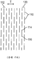
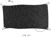
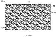
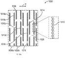
하나의 예시적인 패키징 재료가 도 1a 및 도 1b에 도시되어 있다. 필름(100)은 일종의 단일 슬릿 패턴인 "스킵 슬릿 패턴(skip slit pattern)"으로 종종 지칭되는 복수의 컷(cut)들 또는 슬릿들(110)의 패턴을 포함하는 종이 시트로 제조된다. 필름(100)이 장력 활성화될 때(컷 또는 슬릿(110)에 실질적으로 수직인 장력 축(T)을 따라 당겨질 때), 복수의 빔(130)이 형성되고, 빔(130)은 슬릿들의 인접한 동축 행들 사이의 영역이다. 슬릿(110)에 의해 형성된 빔(130)은 집합적으로 어느 정도의 상향 및 하향 이동을 겪는다(예를 들어, 도 1b 및 도 1d 참조). 이러한 상향 및 하향 이동은, 도 1a의 2차원 물품(실질적으로 평평한 시트)이 장력 활성화될 때 도 1b 및 도 1d의 3차원 물품이 되는 결과를 가져온다. 이러한 필름이 패키징 재료로서 사용될 때, 3차원 구조물은 2차원의 평평한 구조물에 비해 어느 정도의 완충을 제공한다.One exemplary packaging material is shown in FIGS. 1A and 1B .
필름(100)의 컷 또는 슬릿 패턴은 도 1c에 도시되어 있고, 미국 특허 제4,105,724호(Talbot) 및 제5,667,871호(Goodrich 등)에 기재되어 있다. 이러한 패턴은 다수의 개별 선형 슬릿들(110)의 복수의 실질적으로 평행한 행(112)을 포함한다. 주어진 행(112) 내의 개별 선형 슬릿들(110) 각각은, 바로 인접하고 실질적으로 평행한 행(112) 내의 개별 선형 슬릿들(110) 각각과 위상이 다르다. 도 1a 내지 도 1c의 특정 구성에서, 인접한 행들(112)은 수평 간격의 1/2만큼 위상이 다르다. 이러한 패턴은 슬릿들(110)과 행들(112)의 어레이를 형성하고, 어레이는 어레이에 걸쳐 규칙적인 반복 패턴을 갖는다. 슬릿들(110)의 바로 인접한 행들(112) 사이에는 재료의 빔(130)이 형성된다.The cut or slit pattern of the
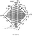
도 2a는, 도 1a 내지 도 1c의 필름(100)의 컷 또는 슬릿 패턴이 90° 회전된 것을 도시한다. 각각의 선형 슬릿(110)은, 제1 종단 단부(114)와 제2 종단 단부(116) 사이에서 연장되는 길이(L)를 갖는다. 각각의 선형 슬릿(110)은, 또한, 제1 종단 단부(114)와 제2 종단 단부(116) 사이의 중간에 있는 중간점(118)을 갖는다. 중간점(118)은 도 2a의 각각의 슬릿(110) 상의 점에 의해 도시되어 있다. 평행하고 정렬된 슬릿(110)의 중간점(118)은 서로 실질적으로 정렬된다. 다시 말해서, 개별 선형 슬릿(110)의 중간점(118)은 장력 축(T)을 따른 바로 인접한 빔(130) 상의 개별 선형 슬릿(110)의 중간점(118)과 실질적으로 정렬된다. 그러한 슬릿(110)은 바로 인접한 슬릿 행들(112) 내에 있지 않으며; 대신에, 그는 교번하는 행들(112) 상에 있다. 추가로, 개별 슬릿(110)의 중간점(118)은 장력 축(T)을 따른 바로 인접한 슬릿들 또는 컷들(110)의 종단 단부들(114, 116) 사이에 있다. 슬릿들(110)의 행(112) 내의 2개의 바로 인접한 슬릿(110)의 중심들 사이의 거리는 횡방향 간격(H)으로서 식별된다. 빔(130)의 두께 또는 인접한 선형 슬릿들(110)의 2개의 인접한 행들(112) 사이의 거리는 축방향 간격(V)으로서 식별된다.FIG. 2A shows the cut or slit pattern of the
더 구체적으로, 도 2a의 실시 형태에서, 슬릿(110A)의 중간점(118A)은 슬릿(110B)의 중간점(118B)과 축방향으로 정렬되며, 이는 중간점(118A, 118B)이 축방향으로 연장되는 축을 따라 정렬된다는 것을 의미한다. 슬릿(110B)은, 슬릿(110A)이 놓이는 빔(130A)에 바로 인접한 빔(130B) 상에 있다. 또한, 슬릿(110A)의 중간점(118A)은 슬릿(110C)의 종단 단부(114C)와 슬릿(110D)의 종단 단부(114D) 사이에 있다. 슬릿(110C, 110D)은 횡방향으로 슬릿(110A)에 바로 인접한다. 도 2a는, 또한, 횡방향으로 인접한 중간점들(118) 사이의 횡방향 피치(H), 축방향 피치(V) 또는 빔(130) 높이, 슬릿 길이(L), 및 빔(130)의 상향 및 하향 이동을 제공하기 위해 장력이 그를 따라 전개될 수 있는 장력 축(T)을 도시한다.More specifically, in the embodiment of FIG. 2A ,
도 2b는, 도 2a의 슬릿 패턴을 포함하는 물품이 장력 축(T)을 따른 장력으로 전개될 때 형성된 주 장력 라인(예컨대, 가장 높은 인장 응력 경로에 근사한 라인)을 도시한다. 도 2b는, 가장 큰 인장 응력이 발생할 위치인 주 장력 라인(140)을 (적색) 점선으로 도시한다. 장력 라인은, 장력이 장력 축을 따라 재료에 인가될 때 가장 큰 하중을 전달하는, 재료를 통한 가상 경로이다. 장력이 장력 축(T)을 따라 인가될 때, 주 장력 라인(140)은 적용된 장력 축(T)과 정렬되도록 더 가깝게 이동하여, 시트가 왜곡되게 한다. 단일 슬릿 패턴이 전개될 때, 주 장력 라인(140)을 따른 장력의 활성화는, 패턴의 실질적으로 모든 영역이 어느 정도의 인장 또는 압축(인장 응력 또는 압축 응력)을 겪게 한 다음에 원래의 2차원 필름의 평면 밖으로 좌굴되고 구부러지게 한다. 일부 실시 형태에서, 필름이 완전히 전개되고/되거나 장력이 원하는 정도로 인가될 때, 시트의 원래 평면에 평행한 상태로 유지되는 영역이 필름에 실질적으로 존재하지 않는다.FIG. 2B depicts a principal tension line (eg, a line approximating the highest tensile stress path) formed when an article comprising the slit pattern of FIG. 2A develops in tension along the tension axis T. FIG. Figure 2b shows the
예시적인 이중 슬릿 패턴화된 재료가 미국 특허 제8,613,993호("'993 특허")에 개시되었으며, 도 3a 및 도 3b에 도시되어 있다. '993 특허는, 도 3a 및 도 3b의 재료를 사용하여 한 품목의 농산물(특히, 여러 포기의 상추) 위에 배치될 랩의 단일 층을 형성하는 것을 설명하고 있으며, 이는 맑고 투명한 탄성 플라스틱 래퍼(wrapper)로 형성된다. "이중 슬릿 패턴"은 복수의 개별 슬릿을 포함한다. 복수의 슬릿 내의 각각의 슬릿은, 교차하거나 자체 교차하지 않는 단일 연속 컷에 의해 형성될 수 있다. 패턴은 슬릿들의 복수의 행을 포함하고, 제1 행 내의 개별 슬릿은 바로 인접한 제2 행 내의 개별 슬릿과 실질적으로 정렬된다. 패턴의 서로 반대편인 측부들 상에 있는, 즉 슬릿의 방향에 수직인 시트의 대각 코너는 결속되기 전에 분리되어 주위 및 아래로 통과한다. 재료는, 도 3b에 도시된 바와 같이, 슬릿이 만들어진 시트가 슬릿에 수직인 방향으로 신장될 때 표면으로부터 "튀어나올" 루프를 형성하는 일련의 슬릿 쌍들을 포함한다. 패턴은 슬릿이 없는 실질적인 경계를 포함하고, 경계에 의해 경계지어지는 별개의 크기로 만들어진다.An exemplary double slit patterned material is disclosed in US Pat. No. 8,613,993 (“the '993 patent”) and is shown in FIGS. 3A and 3B . The '993 patent describes the use of the materials of Figures 3a and 3b to form a single layer of wrap to be placed over an item of produce (especially a bunch of lettuce), which is a clear and transparent elastic plastic wrapper. ) is formed from A “double slit pattern” includes a plurality of individual slits. Each slit in the plurality of slits may be formed by a single continuous cut that either intersects or does not intersect itself. The pattern includes a plurality of rows of slits, wherein individual slits in a first row are substantially aligned with individual slits in an immediately adjacent second row. Diagonal corners of the sheet on opposite sides of the pattern, ie perpendicular to the direction of the slit, are separated and passed around and down before being bound. The material includes a series of pairs of slits that form a loop that will "jump out" from the surface when the sheet from which the slit is stretched in a direction perpendicular to the slit, as shown in FIG. 3B. The pattern includes a substantial boundary without slits and is made of discrete sizes bounded by the boundary.
본 발명의 발명자들은 신규한 이중 슬릿 장력 활성화식 확장 재료 및/또는 물품을 발명하였다. 일부 실시 형태에서, 이중 슬릿 장력 활성화식 확장 재료 및/또는 물품은 배송 및 패키징 응용에 사용된다. 그러나, 이중 슬릿 장력 활성화식 확장 재료 및/또는 물품은 또한 많은 다른 용도 또는 응용에 사용될 수 있다. 따라서, 본 발명은, 단지 하나의 예시적인 용도 또는 응용인 배송 또는 패키징 재료 응용으로 제한되는 것으로 의도되지 않는다.The inventors of the present invention have invented a novel double slit tension activated expanding material and/or article. In some embodiments, double slit tension activated expanding materials and/or articles are used in shipping and packaging applications. However, double slit tension activated expanding materials and/or articles may also be used for many other uses or applications. Accordingly, the present invention is not intended to be limited to shipping or packaging material applications, which are only one exemplary use or application.
일부 실시 형태는, 확장 재료로서, 다중 슬릿 패턴을 형성하는 복수의 슬릿을 포함하는 재료를 포함하고, 각각의 슬릿은 제1 종단 단부 및 제2 종단 단부를 포함하며, 가상 직선이 행 내의 복수의 슬릿 내의 슬릿들 각각의 제1 종단 단부와 제2 종단 단부를 연결하고, 슬릿들의 행과 관련된 가상 직선은 모두 서로 동일 선상에 있지만 슬릿과는 동일 선상에 있지 않은, 확장 재료에 관한 것이다.Some embodiments include, as an expanding material, a material comprising a plurality of slits forming a multiple slit pattern, each slit comprising a first terminal end and a second terminal end, wherein the imaginary straight line comprises a plurality of slits in a row. Connecting the first and second terminal ends of each of the slits in the slit, the imaginary straight lines associated with the row of slits are all collinear with each other but not collinear with the slit.
일부 실시 형태는, 확장 재료로서, 다중 슬릿 패턴을 형성하는 복수의 슬릿을 포함하는 재료를 포함하고, 재료는 사전인장된(pretensioned) 형태에서 실질적으로 평면형이지만, 다중 슬릿 패턴은, 장력 축을 따라 장력이 인가될 때 재료의 적어도 일부분들이 사전인장된 형태에서의 재료의 평면으로부터 45도 이상 회전할 수 있게 하는, 확장 재료에 관한 것이다.Some embodiments include, as an expanding material, a material comprising a plurality of slits forming a multi-slit pattern, wherein the material is substantially planar in a pretensioned configuration, while the multi-slit pattern is formed in tension along a tension axis. wherein, when applied, at least portions of the material are capable of rotating more than 45 degrees from the plane of the material in its pretensioned configuration.
일부 실시 형태는, 확장 재료로서, 다중 슬릿 패턴을 형성하는 복수의 슬릿을 포함하는 재료를 포함하고, 각각의 슬릿은 제1 종단 단부 및 제2 종단 단부를 포함하며, 제1 종단 단부 또는 제2 종단 단부 중 적어도 하나는 만곡되는, 확장 재료에 관한 것이다.Some embodiments include, as an expanding material, a material comprising a plurality of slits forming a multi-slit pattern, each slit comprising a first longitudinal end and a second longitudinal end, the first or second At least one of the terminal ends relates to a curved, expanding material.
일부 실시 형태는, 확장 재료로서, 다중 슬릿 패턴을 형성하는 복수의 슬릿을 포함하는 재료를 포함하고, 각각의 슬릿은 제1 종단 단부 및 제2 종단 단부를 포함하며, 복수의 슬릿 내의 슬릿들 각각은 2개 이상의 극값(extremum)들을 포함하는, 확장 재료에 관한 것이다.Some embodiments include, as an expanding material, a material comprising a plurality of slits forming a multiple slit pattern, each slit including a first terminal end and a second terminal end, each of the slits within the plurality of slits relates to an expanding material, containing two or more extremes.
일부 실시 형태는, 확장 재료로서, 다중 슬릿 패턴을 형성하는 복수의 슬릿을 포함하는 재료를 포함하고, 각각의 슬릿은 후크, 루프, 사인파, 구형파(square-wave), 삼각파 또는 다른 유사하게 형상화된 특징부 중 적어도 하나를 포함하는, 확장 재료에 관한 것이다.Some embodiments include, as an expanding material, a material comprising a plurality of slits forming a multi-slit pattern, each slit having a hook, loop, sine wave, square-wave, triangular wave, or other similarly shaped pattern. to an expanding material comprising at least one of the features.
일부 실시 형태는, 확장 재료로서, 다중 슬릿 패턴을 형성하는 복수의 슬릿을 포함하는 재료를 포함하고, 복수의 슬릿 내의 슬릿들 각각은 하나 이상의 다중빔을 포함하는, 확장 재료에 관한 것이다.Some embodiments are directed to an expanding material comprising, as an expanding material, a material comprising a plurality of slits forming a multi-slit pattern, each of the slits in the plurality of slits comprising one or more multibeams.
일부 실시 형태는, 확장 재료로서, 다중 슬릿 패턴을 형성하는 복수의 슬릿을 포함하는 재료를 포함하고, 슬릿 패턴은 재료의 에지들 중 하나 이상을 통해 연장되는, 확장 재료에 관한 것이다.Some embodiments relate to an expanding material comprising, as an expanding material, a material comprising a plurality of slits forming a multi-slit pattern, the slit pattern extending through one or more of the edges of the material.
이들 실시 형태들 중 일부에서, 재료는, 종이, 골판지, 플라스틱, 탄성 재료, 비탄성 재료, 폴리에스테르, 아크릴, 폴리설폰, 열경화성 수지, 열가소성 수지, 생분해성 중합체 및 이들의 조합 중 적어도 하나를 포함한다. 일부 실시 형태에서, 재료는 종이이고, 두께는 약 0.003 인치(0.076 mm) 내지 약 0.010 인치(0.25 mm)이다. 일부 실시 형태에서, 재료는 플라스틱이고, 두께는 약 0.005 인치(0.13 mm) 내지 약 0.125 인치(3.2 mm)이다. 일부 실시 형태에서, 재료는 본 명세서에서 설명되는 상호로킹 시험을 통과한다. 일부 실시 형태에서, 슬릿은 장력 축에 대체적으로 수직이다. 일부 실시 형태에서, 슬릿은, 반원형, u자형, v자형, 오목형, 볼록형, 곡선형, 선형 또는 이들의 조합 중 적어도 하나인 슬릿 형상을 갖는다. 일부 실시 형태에서, 복수의 슬릿 내의 슬릿은 슬릿의 횡방향 길이의 75% 이하만큼 인접한 행들에서 서로 오프셋된다. 일부 실시 형태에서, 슬릿은 일정 슬릿 형상 및 슬릿 배향을 갖고, 슬릿 형상 및/또는 배향은 슬릿들의 행 내에서 변한다. 일부 실시 형태에서, 슬릿은 일정 슬릿 형상 및 슬릿 배향을 갖고, 슬릿 형상 및/또는 배향은 인접한 행들에서 변한다. 일부 실시 형태에서, 재료는 약 0.001 인치(0.025 mm) 내지 약 5 인치(127 mm)의 두께를 갖는다. 일부 실시 형태에서, 슬릿 패턴은 재료의 에지들 중 하나 이상을 통해 연장된다. 일부 실시 형태에서, 복수의 슬릿 내의 각각의 슬릿은 일정 슬릿 길이를 갖고, 슬릿 길이는 상이하거나 동일하다. 일부 실시 형태에서, 복수의 슬릿 내의 각각의 슬릿은 약 0.25 인치(6.4 mm) 내지 약 3 인치(76.2 mm)인 슬릿 길이를 갖는다. 일부 실시 형태에서, 복수의 슬릿 내의 각각의 슬릿은 일정 슬릿 길이를 갖고, 재료는 일정 재료 두께를 가지며, 슬릿 길이 대 재료 두께의 비는 약 50 내지 약 1000이다. 일부 실시 형태에서, 슬릿의 적어도 일부분은 제1 종단 단부와 제2 종단 단부를 연결하는 가상 직선을 통과한다.In some of these embodiments, the material comprises at least one of paper, corrugated cardboard, plastic, elastic material, inelastic material, polyester, acrylic, polysulfone, thermosetting resin, thermoplastic resin, biodegradable polymer, and combinations thereof. . In some embodiments, the material is paper and has a thickness of from about 0.003 inches (0.076 mm) to about 0.010 inches (0.25 mm). In some embodiments, the material is plastic and has a thickness of from about 0.005 inches (0.13 mm) to about 0.125 inches (3.2 mm). In some embodiments, the material passes the interlocking test described herein. In some embodiments, the slit is generally perpendicular to the tension axis. In some embodiments, the slit has a slit shape that is at least one of semicircular, u-shaped, v-shaped, concave, convex, curved, linear, or combinations thereof. In some embodiments, the slits in the plurality of slits are offset from each other in adjacent rows by no more than 75% of the lateral length of the slits. In some embodiments, the slit has a constant slit shape and slit orientation, and the slit shape and/or orientation varies within a row of slits. In some embodiments, the slit has a constant slit shape and slit orientation, the slit shape and/or orientation changing in adjacent rows. In some embodiments, the material has a thickness of from about 0.001 inches (0.025 mm) to about 5 inches (127 mm). In some embodiments, the slit pattern extends through one or more of the edges of the material. In some embodiments, each slit in the plurality of slits has a constant slit length, the slit lengths being different or the same. In some embodiments, each slit in the plurality of slits has a slit length that is from about 0.25 inches (6.4 mm) to about 3 inches (76.2 mm). In some embodiments, each slit in the plurality of slits has a constant slit length, the material has a constant material thickness, and the ratio of the slit length to the material thickness is between about 50 and about 1000. In some embodiments, at least a portion of the slit passes through an imaginary straight line connecting the first and second longitudinal ends.
일부 실시 형태는 본 명세서에서 설명되는 슬릿 패턴들 중 임의의 슬릿 패턴을 형성할 수 있는 다이에 관한 것이다.Some embodiments relate to dies capable of forming any of the slit patterns described herein.
일부 실시 형태는 본 명세서에서 설명되는 확장 재료들 중 임의의 확장 재료로 형성되는 패키징 재료에 관한 것이다.Some embodiments relate to packaging materials formed from any of the expanding materials described herein.
일부 실시 형태는, 본 명세서에서 설명되는 확장 재료들 중 임의의 확장 재료를 제조하는 방법으로서, 압출, 성형, 레이저 커팅, 워터 젯팅(water jetting), 기계가공, 스테레오리소그래피(stereolithography) 또는 다른 3D 인쇄 기법, 레이저 절제, 포토리소그래피(photolithography), 화학적 에칭, 회전 다이 커팅, 스탬핑(stamping), 다른 적합한 음각 또는 양각 가공 기법 또는 이들의 조합 중 적어도 하나에 의해 재료 내에 단일 슬릿 패턴을 형성하는 단계를 포함하는, 방법에 관한 것이다. 일부 그러한 실시 형태에서, 본 방법은, 장력 축을 따라 확장 재료에 장력을 인가하여 재료가 확장되게 하는 단계를 추가로 포함한다. 일부 실시 형태에서, 장력의 인가는, (1) 슬릿이 개방부를 형성하게 하는 것 및 (2) 슬릿에 인접한 재료가 플랩을 형성하게 하는 것 중 하나 이상을 야기한다. 일부 실시 형태에서, 장력은 손에 의해 또는 기계로 인가된다. 일부 실시 형태에서, 장력 축을 따라 확장 재료에 장력을 인가하는 단계는, 재료가 2차원 구조로부터 3차원 구조로 변화하게 한다. 일부 실시 형태에서, 장력 축을 따른 장력에 노출될 때, (1) 확장 재료 내의 슬릿의 종단 단부가 서로를 향해 당겨져, 확장 재료의 플랩이 재료의 사전인장된 상태에서의 재료의 평면에 대해 상향으로 이동하거나 좌굴되게 하는 것 및/또는 (2) 확장 재료의 빔의 일부분이 재료의 사전인장된 상태에서의 재료의 평면에 대해 하향으로 이동하거나 좌굴되어 개방 부분을 형성하는 것 중 적어도 하나이다. 일부 실시 형태에서, 플랩은, 스케일 형상(scale-shaped), 곡선형, 직사각형, 뾰족한 형상(pointed), 커스프형(cusp-shaped) 또는 이들의 조합 중 적어도 하나인 플랩 형상을 갖는다.Some embodiments provide a method of making any of the expansion materials described herein by extrusion, molding, laser cutting, water jetting, machining, stereolithography, or other 3D printing. forming a single slit pattern in the material by at least one of techniques, laser ablation, photolithography, chemical etching, rotary die cutting, stamping, other suitable engraving or embossing processing techniques, or combinations thereof It's about how to do it. In some such embodiments, the method further comprises applying a tension to the expanding material along the tension axis to cause the material to expand. In some embodiments, the application of the tension causes one or more of (1) causing the slit to form an opening and (2) causing the material adjacent to the slit to form a flap. In some embodiments, the tension is applied by hand or machine. In some embodiments, applying tension to the expanding material along the tension axis causes the material to change from a two-dimensional structure to a three-dimensional structure. In some embodiments, when exposed to tension along a tension axis, (1) the terminal ends of the slits in the expanding material are pulled towards each other, such that the flaps of the expanding material are upwardly relative to the plane of the material in the pretensioned state of the material. at least one of causing it to move or buckle and/or (2) a portion of the beam of expanding material moves or buckles downward relative to the plane of the material in its pretensioned state to form an open portion. In some embodiments, the flap has a flap shape that is at least one of scale-shaped, curved, rectangular, pointed, cusp-shaped, or a combination thereof.
일부 실시 형태는, 추가로, 본 명세서에서 설명되는 확장 재료들 중 임의의 확장 재료를 물품 주위에 래핑(wrapping)하는 것에 관한 것이다. 일부 실시 형태에서, 확장된 재료는 적어도 2개의 완전 랩으로 물품 주위에 래핑되어서, 제1 층 또는 랩 상의 플랩, 개방부 및/또는 상호로킹 특징부 중 적어도 하나가 제2 층 또는 랩 상의 플랩, 개방부 및/또는 상호로킹 특징부 중 적어도 하나와 상호로킹되게 한다.Some embodiments further relate to wrapping any of the expanding materials described herein around an article. In some embodiments, the expanded material is wrapped around the article with at least two full wraps such that at least one of the flaps, openings and/or interlocking features on the first layer or wrap is a flap on the second layer or wrap; interlock with at least one of the openings and/or interlocking features.
도 1a는 종래 기술의 패키징 재료를 형성하는 데 사용되는 단일 슬릿 패턴의 평면 선도(top view line drawing)이다.
도 1b는, 재료 내에 형성되고 장력 축을 따른 장력의 인가에 의해 전개된 도 1a의 패턴의 사시도이다.
도 1c는 도 1b의 재료의 근접한 거의 평면도이다.
도 2a는 예시적인 단일 슬릿 패턴의 평면 선도이다.
도 2b는 주 장력 라인을 도시하는 도 2a의 단일 슬릿 패턴의 평면 선도이다.
도 3a는 종래 기술의 이중 슬릿 패턴화된 재료의 평면 선도이다.
도 3b는 장력에 노출되었을 때의 도 3a의 종래 기술의 재료의 개략적인 평면도이다.
도 4a는 예시적인 이중 슬릿 패턴의 개략 평면도이다.
도 4b는 장력에 노출되었을 때의, 도 4a에 도시된 이중 슬릿 패턴의 주 장력 라인의 개략 평면도이다.
도 5a는 예시적인 이중 슬릿 패턴의 개략 평면도이다.
도 5b는, 종이 시트 내에 형성되고 장력 축을 따른 장력에 노출된 도 5a의 이중 슬릿 패턴의 사진으로부터의 거의 평면도이다.
도 5c는, 종이 시트 내에 형성되고 장력 축을 따른 장력에 노출된 도 5a의 이중 슬릿 패턴의 사진으로부터의 거의 측면도이다.
도 6a는 예시적인 이중 슬릿 패턴의 개략 평면도이다.
도 6b는, 종이 시트 내에 형성되고 장력 축을 따른 장력에 노출된, 도 6a에 도시된 패턴의 사시도 사진이다.
도 6c는, 종이 시트 내에 형성되고 장력 축을 따른 장력에 노출된 도 6a의 이중 슬릿 패턴의 사진으로부터의 거의 평면도이다.
도 6d는, 종이 시트 내에 형성되고 장력 축을 따른 장력에 노출된 도 6a의 이중 슬릿 패턴의 거의 측면도 사진이다.
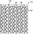
도 7a는 예시적인 이중 슬릿 패턴의 개략 평면도이다.
도 7b는, 종이 시트 내에 형성되고 장력 축을 따른 장력에 노출된, 도 7a에 도시된 패턴의 사진으로부터의 사시도이다.
도 7c는, 종이 시트 내에 형성되고 장력 축을 따른 장력에 노출된 도 7a의 이중 슬릿 패턴의 사진으로부터의 거의 평면도이다.
도 7d는, 종이 시트 내에 형성되고 장력 축을 따른 장력에 노출된 도 7a의 이중 슬릿 패턴의 사진으로부터의 거의 측면도이다.
도 8a는 예시적인 이중 슬릿 패턴의 개략 평면도이다.
도 8b는, 종이 시트 내에 형성되고 장력 축을 따른 장력에 노출된, 도 8a에 도시된 패턴의 사시도 사진이다.
도 8c는, 종이 시트 내에 형성되고 장력 축을 따른 장력에 노출된 도 8a의 이중 슬릿 패턴의 거의 평면도 사진이다.
도 8d는, 종이 시트 내에 형성되고 장력 축을 따른 장력에 노출된 도 8a의 이중 슬릿 패턴의 사진으로부터의 거의 측면도이다.
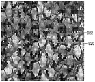
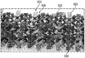
도 9a는 상호로킹 특징부를 포함하는 예시적인 이중 슬릿 패턴의 개략 평면도이다.
도 9b는, 종이 시트 내에 형성되고 장력 축을 따른 장력에 노출된, 도 9a에 도시된 패턴의 사시도 사진이다.
도 9c는, 종이 시트 내에 형성되고 장력 축을 따른 장력에 노출된 도 9a의 이중 슬릿 패턴의 거의 평면도 사진이다.
도 9d는, 종이 시트 내에 형성되고 장력 축을 따른 장력에 노출된 도 9a의 이중 슬릿 패턴의 거의 측면도 사진이다.
도 10a는 상호로킹 특징부를 포함하는 예시적인 이중 슬릿 패턴의 개략 평면도이다.
도 10b는 도 10a의 확대된 부분이다.
도 10c는, 종이 시트 내에 형성되고 장력 축을 따른 장력에 노출된, 도 10a에 도시된 패턴의 사시도 사진이다.
도 10d는, 종이 시트 내에 형성되고 장력 축을 따른 장력에 노출된 도 10a의 이중 슬릿 패턴의 거의 평면도 사진이다.
도 10e는, 종이 시트 내에 형성되고 장력 축을 따른 장력에 노출된 도 10a의 이중 슬릿 패턴의 거의 측면도 사진이다.
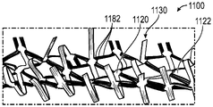
도 11a는 다중빔 슬릿을 포함하는 예시적인 이중 슬릿 패턴의 개략 평면도이다.
도 11b는, 종이 시트 내에 형성되고 장력 축을 따른 장력에 노출된, 도 11a에 도시된 패턴의 사진으로부터의 거의 측면도이다.
도 12a는 예시적인 이중 슬릿 패턴의 개략 평면도이다.
도 12b는 도 12a의 확대된 부분이다.
도 12c는, 종이 시트 내에 형성되고 장력 축을 따른 장력에 노출된, 도 12a에 도시된 패턴의 사진으로부터의 사시도이다.
도 12d는, 종이 시트 내에 형성되고 장력 축을 따른 장력에 노출된 도 12a의 이중 슬릿 패턴의 거의 평면도 사진이다.
도 12e는, 종이 시트 내에 형성되고 장력 축을 따른 장력에 노출된 도 12a의 이중 슬릿 패턴의 거의 측면도 사진이다.
도 13a는 만곡된 종단 단부를 포함하는 예시적인 이중 슬릿 패턴의 개략 평면도이다.
도 13b는, 종이 시트 내에 형성되고 장력 축을 따른 장력에 노출된, 도 13a에 도시된 패턴의 거의 평면도 사진이다.
도 13c는, 종이 시트 내에 형성되고 장력 축을 따른 장력에 노출된 도 13a의 이중 슬릿 패턴의 사시도 사진이다.
도 13d는, 종이 시트 내에 형성되고 장력 축을 따른 장력에 노출된 도 13a의 이중 슬릿 패턴의 사진으로부터의 거의 측면도이다.
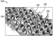
도 14a는 만곡된 종단 단부를 포함하는 예시적인 이중 슬릿 패턴의 개략 평면도이다.
도 14b는, 종이 시트 내에 형성되고 장력 축을 따른 장력에 노출된, 도 14a에 도시된 패턴의 사시도 사진이다.
도 14c는, 종이 시트 내에 형성되고 장력 축을 따른 장력에 노출된 도 14a의 이중 슬릿 패턴의 거의 측면도 사진이다.
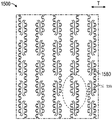
도 15a는 예시적인 이중 슬릿 패턴의 개략 평면도이다.
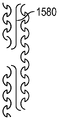
도 15b는 도 15a의 확대된 부분이다.
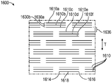
도 16은 예시적인 삼중 슬릿 패턴의 개략 평면도이다.
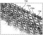
도 17a는 예시적인 삼중 슬릿 패턴의 개략 평면도이다.
도 17b는, 종이 시트 내에 형성되고 장력 축을 따른 장력에 노출된, 도 17a에 도시된 삼중 슬릿 패턴의 사시도 사진이다.
도 17c는, 종이 시트 내에 형성되고 장력 축을 따른 장력에 노출된 도 17a의 삼중 슬릿 패턴의 거의 평면도 사진이다.
도 17d는, 종이 시트 내에 형성되고 장력 축을 따른 장력에 노출된 도 17a의 삼중 슬릿 패턴의 거의 측면도 사진이다.
도 18은 예시적인 사중 슬릿 패턴의 개략 평면도이다.
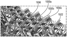
도 19a는 예시적인 사중 슬릿 패턴의 개략 평면도이다.
도 19b는, 종이 시트 내에 형성되고 장력 축을 따른 장력에 노출된, 도 19a에 도시된 사중 슬릿 패턴의 사시도 사진이다.
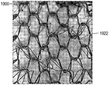
도 19c는, 종이 시트 내에 형성되고 장력 축을 따른 장력에 노출된 도 19a의 사중 슬릿 패턴의 거의 평면도 사진이다.
도 19d는, 종이 시트 내에 형성되고 장력 축을 따른 장력에 노출된 도 19a의 사중 슬릿 패턴의 거의 측면도 사진이다.
도 20은 본 명세서에 개시된 기술과 일관되는 재료를 제조하기 위한 예시적인 시스템이다.1A is a top view line drawing of a single slit pattern used to form prior art packaging materials.
1B is a perspective view of the pattern of FIG. 1A formed in a material and developed by application of tension along a tension axis.
1C is a close-up near top view of the material of FIG. 1B.
2A is a plan view of an exemplary single slit pattern.
FIG. 2B is a plan view of the single slit pattern of FIG. 2A showing main tension lines; FIG.
3A is a plan view of a prior art double slit patterned material.
Fig. 3b is a schematic top view of the prior art material of Fig. 3a when exposed to tension;
4A is a schematic top view of an exemplary double slit pattern.
4B is a schematic plan view of the principal tension lines of the double slit pattern shown in FIG. 4A when exposed to tension;
5A is a schematic top view of an exemplary double slit pattern.
FIG. 5B is a near plan view from a photograph of the double slit pattern of FIG. 5A formed in a sheet of paper and exposed to tension along a tension axis.
FIG. 5C is a near-side view from a photograph of the double slit pattern of FIG. 5A formed in a sheet of paper and exposed to tension along a tension axis.
6A is a schematic top view of an exemplary double slit pattern.
6B is a perspective photograph of the pattern shown in FIG. 6A formed in a sheet of paper and exposed to tension along a tension axis.
6C is a near plan view from a photograph of the double slit pattern of FIG. 6A formed in a sheet of paper and exposed to tension along a tension axis.
FIG. 6D is a near-side view photograph of the double slit pattern of FIG. 6A formed in a sheet of paper and exposed to tension along a tension axis.
7A is a schematic top view of an exemplary double slit pattern.
7B is a perspective view from a photograph of the pattern shown in FIG. 7A formed in a sheet of paper and exposed to tension along a tension axis.
7C is a near plan view from a photograph of the double slit pattern of FIG. 7A formed in a sheet of paper and exposed to tension along a tension axis.
7D is a near side view from a photograph of the double slit pattern of FIG. 7A formed in a sheet of paper and exposed to tension along a tension axis.
8A is a schematic top view of an exemplary double slit pattern.
8B is a perspective photograph of the pattern shown in FIG. 8A formed in a sheet of paper and exposed to tension along a tension axis.
FIG. 8C is a near top view photograph of the double slit pattern of FIG. 8A formed in a sheet of paper and exposed to tension along a tension axis.
FIG. 8D is a near-side view from a photograph of the double slit pattern of FIG. 8A formed in a sheet of paper and exposed to tension along a tension axis.
9A is a schematic top view of an exemplary double slit pattern including interlocking features.
9B is a perspective photograph of the pattern shown in FIG. 9A formed in a sheet of paper and exposed to tension along a tension axis.
9C is a near top view photograph of the double slit pattern of FIG. 9A formed in a sheet of paper and exposed to tension along a tension axis.
9D is a near-side view photograph of the double slit pattern of FIG. 9A formed in a sheet of paper and exposed to tension along a tension axis.
10A is a schematic top view of an exemplary double slit pattern including interlocking features.
Figure 10b is an enlarged portion of Figure 10a.
10C is a perspective photograph of the pattern shown in FIG. 10A formed in a sheet of paper and exposed to tension along a tension axis.
10D is a near top view photograph of the double slit pattern of FIG. 10A formed in a sheet of paper and exposed to tension along a tension axis.
10E is a near-side view photograph of the double slit pattern of FIG. 10A formed in a sheet of paper and exposed to tension along a tension axis.
11A is a schematic plan view of an exemplary double slit pattern including a multibeam slit.
11B is a near-side view from a photograph of the pattern shown in FIG. 11A formed in a sheet of paper and exposed to tension along a tension axis.
12A is a schematic top view of an exemplary double slit pattern.
Figure 12b is an enlarged portion of Figure 12a.
12C is a perspective view from a photograph of the pattern shown in FIG. 12A formed in a sheet of paper and exposed to tension along a tension axis.
12D is a near top view photograph of the double slit pattern of FIG. 12A formed in a sheet of paper and exposed to tension along a tension axis.
12E is a near-side view photograph of the double slit pattern of FIG. 12A formed in a sheet of paper and exposed to tension along a tension axis.
13A is a schematic top view of an exemplary double slit pattern including a curved longitudinal end.
13B is a near top view photograph of the pattern shown in FIG. 13A formed in a sheet of paper and exposed to tension along a tension axis.
13C is a perspective photograph of the double slit pattern of FIG. 13A formed in a sheet of paper and exposed to tension along a tension axis.
FIG. 13D is a near side view from a photograph of the double slit pattern of FIG. 13A formed in a sheet of paper and exposed to tension along a tension axis.
14A is a schematic top view of an exemplary double slit pattern including a curved longitudinal end.
14B is a perspective photograph of the pattern shown in FIG. 14A formed in a sheet of paper and exposed to tension along a tension axis.
14C is a near-side view photograph of the double slit pattern of FIG. 14A formed in a sheet of paper and exposed to tension along a tension axis.
15A is a schematic top view of an exemplary double slit pattern.
Figure 15b is an enlarged portion of Figure 15a.
16 is a schematic plan view of an exemplary triple slit pattern.
17A is a schematic top view of an exemplary triple slit pattern.
17B is a perspective photograph of the triple slit pattern shown in FIG. 17A formed in a sheet of paper and exposed to tension along a tension axis.
17C is a near top view photograph of the triple slit pattern of FIG. 17A formed in a sheet of paper and exposed to tension along a tension axis.
17D is a near-side view photograph of the triple slit pattern of FIG. 17A formed in a sheet of paper and exposed to tension along a tension axis.
18 is a schematic top view of an exemplary quadruple slit pattern.
19A is a schematic top view of an exemplary quadruple slit pattern.
19B is a perspective photograph of the quadruple slit pattern shown in FIG. 19A formed in a sheet of paper and exposed to tension along a tension axis.
19C is a near top view photograph of the quadruple slit pattern of FIG. 19A formed in a sheet of paper and exposed to tension along a tension axis.
19D is a near-side view photograph of the quadruple slit pattern of FIG. 19A formed in a sheet of paper and exposed to tension along a tension axis.
20 is an exemplary system for making a material consistent with the techniques disclosed herein.
본 발명의 다양한 실시 형태는 다중 슬릿 패턴, 및 이러한 다중 슬릿 패턴을 포함하는 물품에 관한 것이다. "슬릿"은 본 명세서에서 적어도 2개의 종단 단부를 갖는, 직선형 또는 곡선형일 수 있는 적어도 하나의 라인을 형성하는, 물품을 통한 좁은 컷으로 정의된다. 본 명세서에서 설명되는 슬릿은 이산적이며, 이는 개별 슬릿이 다른 슬릿과 교차하지 않는다는 것을 의미한다. 슬릿은 일반적으로 컷아웃(cut-out)이 아니며, 여기에서 "컷아웃"은, 슬릿이 자체 교차할 때 시트로부터 제거되는 시트의 표면 영역으로 정의된다. 그러나, 실제로, 많은 형성 기법은 본 출원의 목적을 위해 "컷아웃"으로 간주되지 않는 시트의 일부 표면 영역의 제거를 야기한다. 특히, 많은 커팅 기술은 "커프(kerf)", 또는 어느 정도의 물리적 폭을 갖는 컷을 생성한다. 예를 들어, 레이저 커터는 시트의 일부 표면 영역을 절제하여 슬릿을 생성할 것이고, 라우터(router)는 재료의 일부 표면 영역을 잘라내어 슬릿을 생성할 것이며, 심지어 파쇄 커팅은 재료의 에지 상에 어느 정도의 변형을 생성하여 재료의 표면 영역에 걸쳐 물리적 갭을 형성한다. 게다가, 성형 기법은 슬릿의 서로 반대편인 면들 사이에 재료를 필요로 하여, 슬릿에 갭 또는 커프를 생성한다. 다양한 실시 형태에서, 슬릿의 갭 또는 커프는 재료의 두께 이하일 것이다. 예를 들어, 두께가 .007"인 종이 내에 커팅된 슬릿 패턴은 대략 .007" 이하인 갭을 갖는 슬릿을 가질 수 있다. 그러나, 슬릿의 폭은 재료의 두께보다 몇 배 더 큰 양으로 증가될 수 있고 본 명세서에 개시된 기술과 일관될 수 있는 것으로 이해된다.Various embodiments of the present invention relate to multiple slit patterns and articles comprising such multiple slit patterns. A “slit” is defined herein as a narrow cut through an article that forms at least one line, which may be straight or curved, having at least two terminal ends. The slits described herein are discrete, meaning that individual slits do not intersect other slits. A slit is generally not a cut-out, where "cut-out" is defined as the surface area of the sheet that is removed from the sheet when the slit crosses itself. In practice, however, many forming techniques result in the removal of some surface areas of the sheet that are not considered "cutouts" for the purposes of this application. In particular, many cutting techniques produce cuts with a "kerf," or some degree of physical width. For example, a laser cutter will ablate some surface area of the sheet to create a slit, a router will cut some surface area of the material to create a slit, and even shredded cutting will cut some surface area of the material to some extent on the edge of the material. creates a physical gap across the surface area of the material. In addition, the forming technique requires material between the opposing sides of the slit, creating a gap or kerf in the slit. In various embodiments, the gap or cuff of the slit will be less than or equal to the thickness of the material. For example, a slit pattern cut into paper that is .007" thick may have slits with a gap that is approximately .007" or less. However, it is understood that the width of the slit may be increased by an amount many times greater than the thickness of the material and may be consistent with the techniques disclosed herein.
본 명세서에서 사용되는 바와 같이, 용어 "단일 슬릿 패턴"은, 각각이 횡방향으로 시트를 가로질러 연장되는 개별 행들을 형성하는 개별 슬릿들의 패턴을 지칭하며, 여기에서 행은 시트의 축방향 길이를 따라 개별 행들의 반복 패턴을 형성하고, 각각의 행 내의 슬릿들의 패턴은 바로 인접한 행들 내의 슬릿들의 패턴과는 상이하다. 예를 들어, 하나의 행 내의 슬릿은 바로 인접한 행들 내의 슬릿과 축방향으로 오프셋되거나 위상이 다를 수 있다.As used herein, the term “single slit pattern” refers to a pattern of individual slits, each forming individual rows extending transversely across a sheet, wherein the rows define the axial length of the sheet. thus forming a repeating pattern of individual rows, wherein the pattern of slits in each row is different from the pattern of slits in immediately adjacent rows. For example, a slit in one row may be axially offset or out of phase with a slit in immediately adjacent rows.
용어 "다중 슬릿 패턴"은 본 명세서에서 시트의 횡방향(y)을 가로질러 제1 세트의 인접한 행들을 형성하는 개별 슬릿들의 패턴으로 정의되며, 여기에서 제1 세트의 인접한 행들 내의 개별 슬릿은 횡방향(y)으로 정렬된다. 다중 슬릿 패턴에서, 제1 세트의 인접한 행들은 시트의 축방향 길이를 따라 적어도 제2 행과 반복 패턴을 형성하며, 여기에서 제1 세트의 인접한 동일한 행들 내의 슬릿은 횡방향(y)으로 제2 행 내의 슬릿으로부터 오프셋된다. 용어 "다중 슬릿 패턴"은 이중 슬릿 패턴, 삼중 슬릿 패턴, 사중 슬릿 패턴 등을 포함한다.The term "multiple slit pattern" is defined herein as a pattern of individual slits forming a first set of adjacent rows across the transverse direction (y) of the sheet, wherein the individual slits in the first set of adjacent rows are transverse aligned in the direction (y). In a multiple slit pattern, a first set of adjacent rows forms a repeating pattern with at least a second row along the axial length of the sheet, wherein the slits in the first set of adjacent identical rows form a second row in the transverse direction (y). Offset from the slit in the row. The term "multi-slit pattern" includes double slit patterns, triple slit patterns, quadruple slit patterns, and the like.
본 명세서에서 사용되는 바와 같이, 용어 "이중 슬릿 패턴"은 복수의 개별 슬릿들의 패턴을 지칭한다. 패턴은 슬릿들의 복수의 행을 포함하고, 제1 행 내의 개별 슬릿은 바로 인접한 제2 행 내의 개별 슬릿과 실질적으로 정렬된다. 제2 행 내의 슬릿과 실질적으로 정렬되는 제1 행 내의 슬릿으로 이중 슬릿이 구성된다. 함께, 이들 2개의 실질적으로 정렬된 슬릿은 이중 슬릿 패턴을 형성한다.As used herein, the term “double slit pattern” refers to a pattern of a plurality of individual slits. The pattern includes a plurality of rows of slits, wherein individual slits in a first row are substantially aligned with individual slits in an immediately adjacent second row. A double slit consists of a slit in the first row that is substantially aligned with the slit in the second row. Together, these two substantially aligned slits form a double slit pattern.
본 명세서에서 사용되는 바와 같이, 용어 "삼중 슬릿 패턴"은 복수의 개별 슬릿들의 패턴을 지칭한다. 패턴은 슬릿들의 복수의 행을 포함하고, 제1 행 내의 개별 슬릿은 바로 인접한 제2 행 내의 개별 슬릿과 실질적으로 정렬된다. 제2 행 내의 슬릿은 바로 인접한 제3 행 내의 개별 슬릿과 실질적으로 정렬된다. 제1 행 내의 슬릿, 이와 실질적으로 정렬되는 제2 행 내의 슬릿, 및 이들 둘 모두와 실질적으로 정렬되는 제3 행 내의 슬릿으로 삼중 슬릿이 구성된다. 함께, 이들 3개의 실질적으로 정렬된 슬릿은 삼중 슬릿을 형성한다.As used herein, the term “triple slit pattern” refers to a pattern of a plurality of individual slits. The pattern includes a plurality of rows of slits, wherein individual slits in a first row are substantially aligned with individual slits in an immediately adjacent second row. The slits in the second row are substantially aligned with the respective slits in the immediately adjacent third row. A triple slit consists of a slit in the first row, a slit in the second row substantially aligned therewith, and a slit in the third row substantially aligned with both. Together, these three substantially aligned slits form a triple slit.
본 명세서에서 사용되는 바와 같이, 용어 "사중 슬릿 패턴"은 복수의 개별 슬릿들의 패턴을 지칭한다. 패턴은 슬릿들의 복수의 행을 포함하고, 제1 행 내의 개별 슬릿은 바로 인접한 제2 행 내의 개별 슬릿과 실질적으로 정렬된다. 제2 행 내의 슬릿은 바로 인접한 제3 행 내의 개별 슬릿과 실질적으로 정렬된다. 제3 행 내의 슬릿은 바로 인접한 제4 행 내의 개별 슬릿과 실질적으로 정렬된다. 제1 행 내의 슬릿, 이와 실질적으로 정렬되는 제2 행 내의 슬릿, 이들 둘 모두와 실질적으로 정렬되는 제3 행 내의 슬릿, 및 이들 셋 모두와 실질적으로 정렬되는 제4 행 내의 슬릿으로 사중 슬릿이 구성된다. 함께, 이들 4개의 실질적으로 정렬된 슬릿은 사중 슬릿을 형성한다.As used herein, the term “quadruple slit pattern” refers to a pattern of a plurality of individual slits. The pattern includes a plurality of rows of slits, wherein individual slits in a first row are substantially aligned with individual slits in an immediately adjacent second row. The slits in the second row are substantially aligned with the respective slits in the immediately adjacent third row. The slits in the third row are substantially aligned with the respective slits in the immediately adjacent fourth row. A quadruple slit consists of a slit in a first row, a slit in a second row substantially aligned therewith, a slit in a third row substantially aligned with both, and a slit in a fourth row substantially aligned with all three. do. Together, these four substantially aligned slits form a quadruple slit.
용어 "다중 슬릿 패턴"은 이중 슬릿 패턴, 삼중 슬릿 패턴, 사중 슬릿 패턴 등을 포함한다. 추가로, 용어 "다중 슬릿 패턴"은, 각각 상이한 바로 인접한 행들 내에 있는 2개 이상의 슬릿이 그들의 종단 단부가 실질적으로 정렬되도록 서로 실질적으로 정렬되는 임의의 슬릿 패턴을 포함하도록 의도된다. 정렬된 다중 슬릿의 종단 단부의 실질적인 정렬은, 다중 슬릿의 2개의 인접한 슬릿들 내의 2개의 정렬된 종단 단부들 사이에 가상선을 그리는 경우, 정렬 축(행(들)에 수직인 축)에 대한 가상선의 각도가 +/-20도 이하임을 의미한다. 일부 실시 형태에서, 다중 슬릿을 형성하는 각각의 슬릿의 길이는 가장 긴 또는 가장 짧은 슬릿의 총 길이의 +/-20% 이하만큼 상이하다. 일부 실시 형태에서, 슬릿들이 선형인 경우, 그들은 서로 실질적으로 평행하다. 슬릿이 선형이 아닌 일부 실시 형태에서, 정렬된 다중 슬릿은 모두 +/-20도 내에서 장력 축에 평행하게 실질적으로 정렬된다.The term "multi-slit pattern" includes double slit patterns, triple slit patterns, quadruple slit patterns, and the like. Additionally, the term “multiple slit pattern” is intended to include any slit pattern in which two or more slits, each in different immediately adjacent rows, are substantially aligned with each other such that their terminal ends are substantially aligned. Substantial alignment of the longitudinal ends of an aligned multiple slit is with respect to the alignment axis (the axis perpendicular to the row(s)) if an imaginary line is drawn between the two aligned longitudinal ends in two adjacent slits of the multiple slit. It means that the angle of the imaginary line is +/-20 degrees or less. In some embodiments, the length of each slit forming the multiple slits differs by no more than +/−20% of the total length of the longest or shortest slit. In some embodiments, when the slits are linear, they are substantially parallel to each other. In some embodiments where the slits are not linear, the multiple aligned slits are all aligned substantially parallel to the tension axis within +/-20 degrees.
횡방향 빔(430)의 섹션의 중간점(432)은 (도 4a에 도시된 바와 같이) 횡방향 빔의 그 섹션의 기하학적 중심으로 지칭될 수 있다. 일부 실시 형태에서, 행 내의 개별 슬릿은 1개 초과 및 100만 개 미만의 바로 인접한 행들 내의 개별 슬릿과 실질적으로 정렬된다. 일부 실시 형태에서, 슬릿은 장력 축(T)에 실질적으로 수직이다.The midpoint 432 of a section of the
이중, 삼중, 사중, 또는 다중 슬릿 패턴은 장력 축을 따른 장력에 노출될 때 단일 슬릿 패턴보다 상당히 더 많은 평면외 기복을 생성한다. 재료의 이러한 평면외 기복은 많은 응용에 대해 큰 가치를 갖는다. 예를 들어, 이들 평면외 기복 영역은, 재료의 일부분들이 서로 인접하게 배치되거나 함께 래핑될 때 평면외 재료 또는 루프의 다른 영역과 상호로킹할 수 있는 평면외 재료 또는 루프를 생성한다. 이와 같이, 다중 슬릿 패턴은 본질적으로 상호로킹되고/되거나 상호로킹 특징부를 포함한다. 일단 장력 활성화되면, 이들 특징부 및 패턴은 상호로킹되어 재료를 실질적으로 제자리에 유지한다.Double, triple, quadruple, or multiple slit patterns produce significantly more out-of-plane undulations than single slit patterns when exposed to tension along the tension axis. This out-of-plane undulation of the material is of great value for many applications. For example, these out-of-plane relief regions create an out-of-plane material or loop that can interlock with other regions of the out-of-plane material or loop when portions of the material are placed adjacent to each other or wrapped together. As such, the multiple slit pattern is inherently interlocking and/or including interlocking features. Once tension activated, these features and patterns interlock to hold the material substantially in place.
상호로킹은 하기의 시험 방법에 의해 측정될 수 있다. 길이가 36 인치(0.91 m)이고 폭이 7.5 인치(19 cm)인 샘플을 얻었다. 샘플을 인열 없이 완전히 전개시킨 다음에, 매끄러운 PVC 파이프(예를 들어, 외경(OD)이 3.15 인치(8 cm)이고 길이가 23 인치(58.4 cm)인 것)에 바로 인접하게 배치하여, 샘플이 롤링 동안 완전히 전개된 상태로 유지되는 것을 보장하였다. 샘플을 파이프 위에 래핑(wrapping)하여, 각각의 연속 층이 이전 층 바로 위에 배치되고 샘플이 파이프의 (길이를 따른) 중심에 배치되는 것을 보장하였다. 이는 파이프 주위의 최소 2개의 완전한 랩을 제공할 것이다. 모든 샘플이 파이프 주위에 래핑되었을 때, 샘플을 해제하였고, 샘플이 폴딩해제/래핑해제되는지 여부를 관찰하였다. 1분 대기 후 샘플이 폴딩해제/래핑해제되지 않은 경우, 샘플을 파이프로부터 테이블 상판과 같은 매끄러운 표면 상으로 활주시켰다. 이어서, 샘플의 후미 에지를 들어올려, 샘플이 롤링해제/래핑해제되는지 또는 그의 형상을 유지하는지를 확인하였다.Interlocking can be measured by the following test method. A sample was obtained that was 36 inches (0.91 m) long and 7.5 inches (19 cm) wide. After the sample has been fully developed without tearing, it is placed directly adjacent to a smooth PVC pipe (eg, 3.15 inches (8 cm) outside diameter (OD) and 23 inches (58.4 cm) long) so that the sample It was ensured to remain fully deployed during rolling. The sample was wrapped over the pipe to ensure that each successive layer was placed directly over the previous layer and the sample was centered (along the length) of the pipe. This will provide at least two complete wraps around the pipe. When all samples were wrapped around the pipe, the samples were released and it was observed whether the samples were unfolded/unwrapped. If the sample had not been unfolded/unwrapped after waiting 1 minute, the sample was slid from the pipe onto a smooth surface such as a table top. The trailing edge of the sample was then lifted to see if the sample was unrolled/unwrapped or retained its shape.
샘플이 해제된 지 1분 내에, 그를 파이프로부터 활주시키는 동안, 또는 그의 후미 에지를 들어 올릴 때, 펴지거나/래핑해제된 경우, 샘플은 "상호로킹되지 않은" 것으로 간주되었다. 샘플이 그를 파이프로부터 활주시키는 동안 및 그 후에 그리고 그의 후미 에지를 들어 올릴 때 그의 튜브형 형상을 유지한 경우, 그는 상호로킹된 것으로 간주되었다. 이러한 시험을 각각의 샘플에 대해 10회 반복하였다.A sample was considered "uninterlocked" if it was unfolded/unwrapped within 1 minute of being released, while sliding it from the pipe, or when lifting its trailing edge. If the sample retained its tubular shape while and after sliding it from the pipe and when lifting its trailing edge, it was considered interlocked. This test was repeated 10 times for each sample.
기복은, 또한, 상당한 소성 변형 없이 스프링 유사 방식으로 에너지를 흡수할 수 있는 구조물을 생성한다. 이중 슬릿 패턴이 (예를 들어, 종이와 같은) 2차원 물품 내에 커팅되고 장력이 장력 축(T)을 따라 물품에 인가될 때, 2차원 물품의 일부분들은 z축(2차원 물품의 원래의 평면에 수직인 축)으로 기복하거나 이동하여, 3차원 물품의 형성을 야기한다. 일부 실시 형태에서, 본 명세서에서 설명되는 슬릿 또는 플랩 형상은 도 1a 내지 도 3b의 종래 기술의 슬릿 형상 및/또는 배향과 비교하여 재료 또는 물품의 평면외 운동을 증폭시킨다. 일부 실시 형태에서, 이중 슬릿 패턴이 형성되는 재료는 실질적으로 비신장성이다. 일부 실시 형태에서, 이중 슬릿 패턴은 중단 또는 변경 없이 재료의 적어도 하나의 에지를 통해 계속되고 그에 의해 절단된다. 생성된 재료 및/또는 물품은 매우 다양한 이점을 제공한다.The undulations also create structures that can absorb energy in a spring-like manner without significant plastic deformation. When a double slit pattern is cut into a two-dimensional article (eg, such as paper) and a tension is applied to the article along the tension axis T, portions of the two-dimensional article move along the z-axis (the original plane of the two-dimensional article). undulate or move along an axis perpendicular to), resulting in the formation of a three-dimensional article. In some embodiments, the slit or flap shapes described herein amplify out-of-plane motion of the material or article as compared to the prior art slit shapes and/or orientations of FIGS. 1A-3B . In some embodiments, the material from which the double slit pattern is formed is substantially inextensible. In some embodiments, the double slit pattern continues through and cuts through at least one edge of the material without interruption or alteration. The resulting materials and/or articles provide a wide variety of advantages.
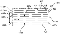
도 4a는 예시적인 이중 슬릿 패턴의 개략도이다. 패턴(400)은 복수의 슬릿(410)을 슬릿들의 행(412) 내에 포함한다. 각각의 슬릿(410)은 제1 종단 단부(414)와 제2 종단 단부(416) 사이의 중간점(418)을 포함한다. 슬릿들(410)의 제1 행(412a) 및 슬릿들(410)의 제2 행(412b) 각각은 서로 이격되는 복수의 슬릿(410)을 포함한다. 횡방향 빔(430)의 인접한 부분들과 조합된 행(412) 내의 바로 인접한 슬릿들(410) 사이의 축방향 공간은 행(412) 내의 인접한 슬릿들(410) 사이의 축방향 빔(420)을 형성할 수 있다. 도 4a의 예시적인 실시 형태에서, 직선형 가상선이 종단 단부들(414, 416) 사이에서 연장되고 그들을 연결한다. 이러한 예시적인 실시 형태에서, 제1 슬릿의 종단 단부들 사이에서 연장되고 그들을 연결하는 직선형 가상선은, 동일한 행 내의 바로 인접한 제2 슬릿의 종단 단부들 사이에서 연장되고 그들을 연결하는 직선형 가상선과 실질적으로 동일 선상에 있다. 이러한 예시적인 실시 형태에서, 단일 행 내의 슬릿 종단 단부들 사이에서 연장되고 그들을 연결하는 모든 직선형 가상선은 대략 동일 선상에 있다.4A is a schematic diagram of an exemplary double slit pattern. The
함께, 슬릿들(410)의 행(412a, 412b)은 횡방향 빔(430)을 형성한다. 횡방향 빔(430)은 슬릿(410)에 의해 축방향으로 경계지어진다. 중첩 빔(436)이 각각의 횡방향 빔(430)에 바로 인접하고 이러한 실시 형태에서 그의 양 측부 상에 있다. 중첩 빔(436)은 비정렬된 슬릿에 의해 축방향으로 경계지어진다. 횡방향 빔(430)의 에지 또는 측부를 형성하는 각각의 바로 인접한 행(412a, 412b) 내의 슬릿들은, 그들이 실질적으로 평행하고 그들의 종단 단부(414, 416)가 행의 축에 수직으로 그리고 서로 등거리로 실질적으로 정렬되도록 서로 실질적으로 정렬된다. 일부 실시 형태에서, 정렬된 슬릿은 실질적으로 동일한 슬릿 길이 및 피치(피치는 장력 축에 대한 것임)를 갖는다.Together,
2개의 평행하고 실질적으로 정렬된 슬릿(410)에 의해 경계지어지는 횡방향 빔(430)의 각각의 섹션은, (1) 횡방향 빔(430)의 측부를 형성하는 슬릿(410)의 제1 종단 단부(414)와 제2 종단 단부(416) 사이의 (횡방향으로의) 중간점에 그리고 (2) 횡방향 빔(430)의 측부를 형성하는 2개의 슬릿들(410) 사이의 (축방향으로의) 중간점에 있는 중간점(432)을 포함한다. 횡방향 빔(430a)의 제1 섹션의 중간점(432a)은 바로 인접한 횡방향 빔(430b)의 바로 인접한 섹션의 중간점(432b)과 위상이 다르다. 도 4a의 실시 형태에서, 횡방향 빔(430a)의 제1 섹션의 중간점(432a)은 횡방향 빔(430a)으로부터의 제2 바로 인접한 횡방향 빔인 횡방향 빔(430c)의 제1 섹션의 중간점(432c)과 축방향으로 실질적으로 정렬된다.Each section of the
도 4a는, 또한, 도 4a의 실시 형태에서, 축방향에 실질적으로 평행하고 횡방향 및 슬릿들의 행의 방향에 실질적으로 수직인 장력 축(T)을 도시한다. 장력 축(T)은, 패턴(400)이 형성된 재료를 전개하기 위해 장력이 그를 따라 제공될 수 있는 축이며, 장력은 횡방향 빔(430)의 상향 및 하향 이동과 중첩 빔(436)의 회전을 일으킨다.FIG. 4a also shows, in the embodiment of FIG. 4a , the tension axis T substantially parallel to the axial direction and substantially perpendicular to the transverse direction and the direction of the row of slits. Tension axis T is an axis along which tension can be provided to unfold the material on which
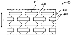
도 4b는, 도 4a의 슬릿 패턴을 포함하는 물품이 장력 축(T)을 따른 장력으로 전개될 때 형성된 주 장력 라인(440)(예컨대, 가장 높은 인장 응력 경로에 근사한 라인)을 도시한다. 도 4b는, 가장 큰 인장 응력이 발생할 위치인 주 장력 라인(440)을 파선으로 도시한다. 장력 라인은, 장력이 장력 축을 따라 재료에 인가될 때 가장 큰 하중을 전달하는, 재료를 통한 가상 경로이다. 장력이 장력 축(T)을 따라 인가될 때, 주 장력 라인(440)은 적용된 장력 축과 정렬되도록 더 가깝게 이동하여, 시트가 왜곡되게 한다. 다중 슬릿 패턴이 전개될 때, 주 장력 라인(440)을 따른 장력의 활성화는, 패턴의 실질적으로 모든 영역이 어느 정도의 인장 또는 압축(인장 응력 또는 압축 응력)을 겪게 하고, 이어서 영역들 중 많은 것이 원래의 2차원 필름의 평면 밖으로 좌굴되고 구부러진다.FIG. 4B depicts a major tension line 440 (eg, a line that approximates the highest tensile stress path) formed when an article comprising the slit pattern of FIG. 4A is developed in tension along the tension axis T. Figure 4b shows the
장력이 이중 슬릿 패턴을 포함하는 재료, 시트 또는 필름에 인가될 때, 정렬된 슬릿들(410)의 쌍들 사이의 횡방향 빔(430)의 일부분들은 주로 압축 응력을 겪으며, 이는, 빔(430)이 시트의 원래 평면 밖으로 좌굴되어 기복부 또는 루프 형상을 형성하면서 장력 축에 공칭적으로 평행하게 유지되게 한다. 중첩 빔(436)은, 그가 이들 인장력을 겪음에 따라 원래 재료 또는 시트의 평면 밖으로 좌굴되고 구부러진다. 횡방향 빔(430)에서, 축방향 빔(420)으로 불리우는 슬릿 쌍들 사이의 영역만이 장력(및 인장 응력)을 겪고, 그를 슬릿들(410)의 다음 행(412)으로 전달한다. 횡방향 빔(430)의 인접한 부분들과 조합된 단일 행(412) 내의 바로 인접한 슬릿들(410) 사이의 축방향 빔(420)은 가장 큰 응력이 발생하는 에지 상에 파선으로 표시된다. 이들 장력 지지 영역은, 장력이 인가될 때 비교적 평평한 상태로 그리고 재료 또는 시트의 사전인장된 평면에 평행한 상태로 유지된다. 이들 장력 지지 영역은 회전하지 않는데, 그 이유는 그들을 통한 장력 라인이 주 장력 축(T)에 실질적으로 평행하기 때문이다.When a tension is applied to a material, sheet or film comprising a double slit pattern, portions of the
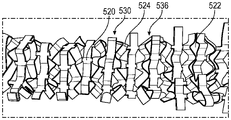
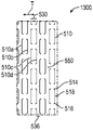
이중 슬릿 패턴의 일례가 도 4a에 도시된 것과 유사한 이중 슬릿 패턴을 포함하는 재료의 개략 평면도인 도 5a에 도시되어 있다. 재료(500)는 슬릿(510a, 510b, 510c, 510d)을 포함한다. 함께, 슬릿(510a, 510b)은 이중 슬릿을 형성한다. 또한, 함께, 슬릿(510c, 510d)은 다른 이중 슬릿을 형성한다. 슬릿(510a, 510b)은 제1 횡방향 빔(530a)의 일부분의 측부 또는 에지를 형성한다. 슬릿(510b, 510c)은 중첩 빔(536)의 일부분의 측부 또는 에지를 형성한다. 슬릿(510c, 510d)은 제2 횡방향 빔(530b)의 일부분의 측부 또는 에지를 형성한다. 제1 횡방향 빔(530a)이 중첩 빔(536)에 바로 인접한다. 중첩 빔(536)은 제2 횡방향 빔(530b)에 바로 인접한다. 슬릿(510a, 510b)은 서로 실질적으로 정렬된다. 슬릿(510c, 510d)은 서로 실질적으로 정렬된다. 슬릿(510b, 510c)은 서로 정렬되지 않는다. 대신에, 슬릿(510b, 510c)은 서로 위상 분리되거나 이격된다. 도 5a의 실시 형태에서, 슬릿(510)은 장력 축 (T)에 실질적으로 수직이다.An example of a double slit pattern is shown in Fig. 5A, which is a schematic top view of a material comprising a double slit pattern similar to that shown in Fig. 4A.
도 5b 및 도 5c는 장력 축(T)을 따른 장력에 노출되었을 때의, 도 5a의 슬릿 패턴을 포함하는 재료의 도면이다. 재료(500)가 장력 축(T)을 따라 장력 활성화되거나 전개될 때, 재료(500)의 일부분들은, 재료(500)가 그의 비인장된 형태에서의 재료(500)의 원래 평면 밖으로 이동하게 하는 인장 및/또는 압축을 겪는다. 장력 축을 따른 장력에 노출될 때, 종단 단부(514, 516)는 압축을 겪고 서로를 향해 당겨져, 재료(500)의 플랩 영역(550)이 재료의 사전인장된 상태(도 5a)에서의 재료(500)의 평면에 대해 상향으로 이동 또는 좌굴되게 하여서, 플랩(524)을 생성한다. 바로 실질적으로 정렬된 인접한 빔들 사이에 있는 횡방향 빔(530)의 일부분들은 재료의 사전인장된 상태(도 5a)에서의 재료(500)의 원래 평면 밖으로 기복하여 루프를 형성하면서, 장력 축에 공칭적으로 평행하게 유지된다. 횡방향 빔(530)의 인접한 부분들과 조합된 행(512) 내의 인접한 슬릿들(510) 사이의 축방향 빔(520)은 재료의 사전인장된 상태(도 5a)에서의 재료(500)의 원래 평면에 실질적으로 평행하게 유지된다. 중첩 빔(536)은 원래 재료 또는 시트의 평면 밖으로 좌굴 및 회전한다. 횡방향 빔(530)의 기복과 조합된 플랩 영역(550)의 운동은 개방 부분(522)을 생성한다.5B and 5C are diagrams of a material comprising the slit pattern of FIG. 5A when exposed to tension along the tension axis T; When the
당업자는, 여전히 본 발명의 범주 내에 속하면서 패턴 및 재료에 대해 많은 변경이 이루어질 수 있다는 것을 인식할 것이다. 예를 들어, 일부 실시 형태에서, 다중 슬릿 패턴은 이중 슬릿 패턴 대신에 삼중 슬릿, 사중 슬릿, 또는 다른 다중 슬릿일 것이다. 대안적으로, 슬릿 길이, 슬릿 크기, 슬릿 두께, 슬릿 형상, 행 크기 또는 형상, 횡방향 빔 크기 또는 형상, 및/또는 중첩 빔 크기 또는 형상이 달라질 수 있다. 추가로, 오프셋 또는 위상 오프셋의 정도가 도시된 것과는 다를 수 있다. 슬릿, 행, 또는 빔 피치가 달라질 수 있다. 장력 축과 슬릿 사이의 각도가 달라질 수 있다. 이들 변경들 중 많은 것이 전개 패턴을 변경할 수 있다.Those skilled in the art will recognize that many changes can be made to the pattern and material while still falling within the scope of the present invention. For example, in some embodiments, the multiple slit pattern will be a triple slit, a quadruple slit, or other multiple slits instead of a double slit pattern. Alternatively, the slit length, slit size, slit thickness, slit shape, row size or shape, transverse beam size or shape, and/or overlapping beam size or shape may vary. Additionally, the degree of offset or phase offset may be different from that shown. The slit, row, or beam pitch may vary. The angle between the tension axis and the slit may vary. Many of these changes can change the deployment pattern.
장력 활성화식 재료(500)가 물품 주위에 래핑되거나 그 자체에 바로 인접하게 배치될 때, 횡방향 빔(530) 및/또는 플랩(524)은 서로 그리고/또는 개방 부분(522)과 상호로킹되어 상호로킹 구조물을 생성한다. 상호로킹은 위에서 설명된 상호로킹 시험에서 언급된 바와 같이 측정될 수 있다.When the tension-activated
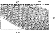
다른 이중 슬릿 패턴의 하나의 예시적인 실시 형태가 도 6a에 개략적으로 도시되어 있다. 이중 슬릿 패턴은 재료(600) 내에 형성되고, 제1 종단 단부(614), 제2 종단 단부(616) 및 중간점(618)을 각각 포함하는 복수의 슬릿(610)을 포함한다. 복수의 개별 슬릿(610)이 장력 축(T)에 대체적으로 수직인 행(612)을 형성하도록 정렬된다. "대체적으로 수직"은 본 명세서에서 5도의 오차 범위 또는 3도의 오차 범위 내의 각도를 포함하는 것으로 정의된다. 축방향 빔(620)을 한정하는 재료가 횡방향 빔(630)의 인접한 부분들과 조합하여 행(612) 내의 인접한 슬릿들(610) 사이에 존재한다. 도 6a의 예시적인 실시 형태에서, 슬릿(610)은 (도 5a의 슬릿 패턴의 슬릿(510)과 같은) 직선이 아니라, 대신에, 2개의 최고점(602, 604) 및 하나의 최저점(606)을 포함하는 만곡된 슬릿이다. 최고점 및 최저점은 극값의 예이며, 여기에서 극값은 축방향 피크(peak)(602, 604) 또는 축방향 밸리(valley)(606)를 한정하는 슬릿의 영역으로 정의된다. 최고점(602, 604) 및 최저점(606)은 종단 단부들(614, 616) 사이에서 연장되는 가상 직선으로부터 이격된다. 플랩 영역(626)은, 대체적으로, 종단 단부들(614, 616) 사이의 가상 직선과 슬릿(610)의 경로에 의해 둘러싸인 영역이다.One exemplary embodiment of another double slit pattern is schematically illustrated in FIG. 6A . The double slit pattern is formed in the
재료(600)는 슬릿(610a, 610b, 610c, 610d)을 포함한다. 슬릿(610a, 610b)은 제1 횡방향 빔(630a)의 일부분의 측부 또는 에지를 형성한다. 슬릿(610b, 610c)은 중첩 빔(636)의 일부분의 측부 또는 에지를 형성한다. 슬릿(610c, 610d)은 제2 횡방향 빔(630b)의 일부분의 측부 또는 에지를 형성한다. 제1 횡방향 빔(630a)이 중첩 빔(636)에 바로 인접한다. 중첩 빔(636)은 제2 횡방향 빔(630b)에 바로 인접한다. 슬릿(610a, 610b)은 서로 실질적으로 정렬된다. 슬릿(610c, 610d)은 서로 실질적으로 정렬된다. 슬릿(610b, 610c)은 서로 정렬되지 않는다. 대신에, 슬릿(610b, 610c)은 서로 위상 분리되거나 이격된다. 도 6a의 실시 형태에서, 슬릿(610)은 장력 축 (T)에 실질적으로 수직이다.
이러한 예시적인 실시 형태에서, 슬릿은 정확히 2개의 종단 단부를 갖는 슬릿으로 본 명세서에서 정의되는 "단순 슬릿"이다. 일부 다른 실시 형태에서, 슬릿들 중 적어도 일부는 2개 초과의 종단 단부를 갖는 슬릿인 "복합 슬릿"일 수 있다. 현재 예에서, 직선형 가상선이 이들 종단 단부들 사이에서 연장되고 그들을 연결한다. 이러한 실시 형태에서, 제1 슬릿의 종단 단부들 사이에서 연장되고 그들을 연결하는 직선형 가상선은, 동일한 행 내의 바로 인접한 슬릿의 종단 단부들 사이에서 연장되고 그들을 연결하는 직선형 가상선과 실질적으로 동일 선상에 있다. 이러한 예시적인 실시 형태에서, 단일 행 내의 슬릿 종단 단부들 사이에서 연장되고 그들을 연결하는 모든 직선형 가상선은 대략 동일 선상에 있다.In this exemplary embodiment, the slit is a “simple slit,” defined herein as a slit having exactly two terminal ends. In some other embodiments, at least some of the slits may be “composite slits,” which are slits having more than two terminal ends. In the present example, a straight imaginary line extends between and connects these longitudinal ends. In this embodiment, the straight imaginary line extending between and connecting the terminal ends of the first slit is substantially collinear with the straight imaginary line extending between and connecting the terminal ends of immediately adjacent slits in the same row. . In this exemplary embodiment, all straight imaginary lines extending between and connecting the slit terminal ends in a single row are approximately collinear.
도 6b 및 도 6c는 장력 축(T)을 따른 장력에 노출되었을 때의, 도 6a의 슬릿 패턴을 포함하는 재료를 도시한다. 재료(600)가 장력 축(T)을 따라 장력 활성화되거나 전개될 때, 재료(600)의 일부분들은, 재료(600)가 그의 비인장된 형태에서의 재료(600)의 원래 평면 밖으로 이동하게 하는 인장 및/또는 압축을 겪는다. 장력 축을 따른 장력에 노출될 때, 종단 단부(614, 616)는 압축을 겪고 서로를 향해 당겨져, 재료(600)의 플랩 영역(626)이 재료의 사전인장된 상태(도 6a)에서의 재료(600)의 평면에 대해 상향으로 이동 또는 좌굴되게 하여서, 플랩(624)을 생성한다. 횡방향 빔(630)의 일부분들은 재료의 사전인장된 상태(도 6a)에서의 재료(600)의 원래 평면 밖으로 기복하여 루프를 형성하면서, 장력 축에 공칭적으로 평행하게 유지된다. 횡방향 빔(630)의 인접한 부분들과 조합된 행(612) 내의 인접한 슬릿들(610) 사이의 축방향 빔(620)은 재료의 사전인장된 상태(도 6a)에서의 재료(600)의 원래 평면에 실질적으로 평행하게 유지된다. 중첩 빔(636)은 원래 재료 또는 시트의 평면 밖으로 좌굴 및 회전한다. 횡방향 빔(630)의 기복과 조합된 플랩 영역(626)의 운동은 개방 부분(622)을 생성한다.6b and 6c show the material comprising the slit pattern of FIG. 6a when exposed to tension along the tension axis T; When the
당업자는, 여전히 본 발명의 범주 내에 속하면서 패턴 및 재료에 대해 많은 변경이 이루어질 수 있다는 것을 인식할 것이다. 예를 들어, 일부 실시 형태에서, 다중 슬릿 패턴은 이중 슬릿 패턴 대신에 삼중 슬릿, 사중 슬릿, 또는 다른 다중 슬릿일 것이다. 대안적으로, 슬릿 길이, 슬릿 크기, 슬릿 두께, 슬릿 형상, 행 크기 또는 형상, 횡방향 빔 크기 또는 형상, 및/또는 중첩 빔 크기 또는 형상이 달라질 수 있다. 도 6a에 도시된 곡률의 정도 및 슬릿 길이는 달라질 수 있다. 추가로, 오프셋 또는 위상 오프셋의 정도가 도시된 것과는 다를 수 있다. 슬릿, 행, 또는 빔 피치가 달라질 수 있다. 장력 축과 슬릿 사이의 각도가 달라질 수 있다. 이들 변경들 중 많은 것이 전개 패턴을 변경할 수 있다.Those skilled in the art will recognize that many changes can be made to the pattern and material while still falling within the scope of the present invention. For example, in some embodiments, the multiple slit pattern will be a triple slit, a quadruple slit, or other multiple slits instead of a double slit pattern. Alternatively, the slit length, slit size, slit thickness, slit shape, row size or shape, transverse beam size or shape, and/or overlapping beam size or shape may vary. The degree of curvature and the slit length shown in FIG. 6A may vary. Additionally, the degree of offset or phase offset may be different from that shown. The slit, row, or beam pitch may vary. The angle between the tension axis and the slit may vary. Many of these changes can change the deployment pattern.
장력 활성화식 재료(600)가 물품 주위에 래핑되거나 그 자체에 바로 인접하게 배치될 때, 빔(630) 및/또는 플랩(624)은 서로 그리고/또는 개방 부분(622)과 상호로킹되어 상호로킹 구조물을 생성한다. 상호로킹은 위에서 설명된 상호로킹 시험에서 언급된 바와 같이 측정될 수 있다.When the tension-activated
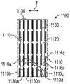
재료(700)의 시트 내의 다른 이중 슬릿 패턴의 하나의 예시적인 실시 형태가 도 7a에 개략적으로 도시되어 있다. 재료(700)의 시트는 축방향(x) 및 횡방향(y)을 한정하며, 여기에서 축방향은 장력 축(T)에 평행하다. 도 7a의 슬릿 패턴은, 상이한 행이 상이하게 위치된 슬릿을 가질 수 있음을 보여준다. 이러한 대체적인 개념의 구현예를 일례로 구체적으로 참조하면, 도 7a의 단일 슬릿 패턴은, 제1 형상 및 위치의 슬릿(710)을 포함하는 제1 세트의 행들(712a), 및 동일한 슬릿 형상을 포함하지만 슬릿(710)이 상이하게 위치되고(이 경우에, 반전됨) 축방향(x)으로 오프셋되는 제2 세트의 행들(712b)을 포함한다. 제1 세트의 행들(712a) 및 제2 세트의 행들(712b) 둘 모두에서의 슬릿 형상은 반전을 제외하고는 실질적으로 동일하다. 상이하게 위치되는 것에 더하여, 도 7a의 슬릿은, 인접한 행들 내의 슬릿(710)의 종단 단부가 횡축을 따라 정렬되도록, 또는 하나의 행 내의 슬릿(710)이 인접한 행 내의 슬릿(710)의 종단 단부에 의해 한정되는 축을 지나 연장되어 네스팅된 배열을 생성하도록 네스팅된다.One exemplary embodiment of another double slit pattern in a sheet of
이중 슬릿 패턴은 재료(700) 내에 형성되고, 제1 종단 단부(714), 제2 종단 단부(716) 및 중간점(718)을 각각 포함하는 복수의 슬릿(710)을 포함한다. 복수의 개별 슬릿(710)이 장력 축(T)에 대체적으로 수직인 행(712)을 형성하도록 정렬된다. 축방향 빔(720)을 형성하는 재료가 횡방향 빔(730)의 인접한 부분(들)과 조합하여 행(712) 내의 인접한 슬릿들(710) 사이에 존재한다. 도 7a의 예시적인 실시 형태에서, 슬릿(710)은 (도 6a의 슬릿 패턴의 슬릿(610)과 같은) 이산된 직선이 아니라, 대신에, 장력 축(T)에 대체적으로 평행하고 장력 축(T)에 대체적으로 수직인 대체적으로 횡방향인 부분(725)에 연결되는 2개의 대체적으로 축방향인 부분(721, 723)을 포함한다. 이러한 실시 형태에서, 슬릿(710)은 대체적으로 u자형이고, 축방향 부분(721, 723)과 대체적으로 횡방향인 부분(725)의 교차점은 서로 대체적으로 수직이다.The double slit pattern is formed in the
시트(700)를 통한 복수의 슬릿(710)은 시트의 축방향 길이를 따라 열로 배열되는 복수의 축방향 연장 빔(720)을 한정한다. 복수의 슬릿(710)은 제1 열(702a)을 형성하는 제1 복수의 축방향 빔(720a)을 형성한다. 복수의 슬릿들(710) 중 하나의 슬릿의 횡방향 부분(725)이 빔들(720a) 사이에 축방향으로 배치된다. 이전에 설명된 예와는 달리, 이러한 예에서, 각각의 빔은 슬릿(710)의 횡방향 부분(725)에 의해 분리되지 않는다. 오히려, 제1 열(702a) 내의 각각의 일련의 2개의 빔(720a)은 열 내의 대응하는 슬릿(710)의 일련의 2개의 횡방향 부분(725)과 교번한다. 이와 같이, 제1 열(702a)은 제1 복수의 빔(720a) 내의 빔들 사이에 축방향으로 있는 횡방향 부분(725a)을 각각 갖는 제1 그룹의 슬릿들(740a)을 갖는다.A plurality of
복수의 슬릿(710)은, 또한, 축방향(x)으로 연장되는 제2 복수의 빔(720b)을 한정한다. 제2 복수의 빔(720b)은 축방향(x)으로 시트(700)를 가로질러 연장되는 제2 열(702b)을 형성한다. 제2 복수의 빔(720b)은 횡방향(y)으로 제1 복수의 빔(720a)으로부터 이격된다. 축방향(x)으로 빔들(720b) 사이에는 복수의 슬릿들(710) 중 제2 그룹의 슬릿들(740b) 내의 하나의 슬릿의 횡방향 부분(725)이 있다. 제1 열(702a)과 유사하게, 이러한 예에서, 제2 열(702b)에서는, 열(702b)의 길이를 따라 슬릿의 2개의 연속 횡방향 부분(725)과 교번하는 일련의 2개의 연속 빔(720b)이 있다.The plurality of
제1 복수의 빔(720a)과 제2 복수의 빔(720b)은 축방향 및 횡방향으로 엇갈리게 배치된다. 현재 예에서, 제1 그룹의 슬릿들(740a) 내의 각각의 슬릿은 제2 복수의 빔들(720b) 중 하나의 빔을 한정하는 축방향 부분(721)(제1 축방향 부분(721))을 갖는다. 복수의 슬릿들(710) 중 제2 그룹의 슬릿들(740b) 내의 각각의 슬릿은 제1 복수의 빔들(720a) 중 하나의 빔을 한정하는 축방향 부분(723)(제2 축방향 부분(723))을 갖는다. 제1 복수의 빔들(720a) 중 각각의 빔은 제2 복수의 빔들(720b) 중 하나의 빔의 종단부(724b)에 의해 한정되는 축(일례로서, i1)과 정렬된다.The first plurality of
현재 실시 형태에서, 재료(700)의 시트는, 제1 열(702a) 내의 제1 복수의 빔(720a) 및 제2 열(702b) 내의 제2 복수의 빔(720b)을 한정하는 복수의 슬릿(710)을 한정한다. 제1 열(702a)과 제2 열(702b)은 횡방향(y)으로 시트의 폭을 가로질러 교번한다. 다시 말해서, 제1 복수의 빔(720a)과 제2 복수의 빔(720b)은 재료(700)의 시트의 횡방향 폭에 걸쳐 빔들의 반복 패턴을 형성한다. 일부 실시 형태에서, 복수의 슬릿(710)은, 유사하게, 시트의 폭을 가로질러 제1 열(702a) 및 제2 열(702b)과 교번하는 제3 열을 한정하는 제3 복수의 빔을 한정할 수 있다. 일부 실시 형태에서, 복수의 슬릿(710)은, 유사하게, 시트의 폭을 가로질러 제1 열(702a), 제2 열(702b) 및 제3 열과 교번하는 제4 열을 한정하는 제4 복수의 빔을 한정할 수 있다.In the present embodiment, the sheet of
재료(700)는 제1 슬릿(710a), 제2 슬릿(710b), 제3 슬릿(710c) 및 제4 슬릿(710d)을 포함하며, 이들 각각은 대응하는 제1 행(712a), 제2 행(712b), 제3 행(712c) 및 제4 행(712d)을 각각 형성한다. 슬릿들의 각각의 행은 횡방향(y)으로 재료(700)의 시트의 폭을 가로질러 연장된다. 제1 행(712a), 제2 행(712b), 제3 행(712c) 및 제4 행(712d)은 재료(700)의 시트의 축방향 길이를 따라 행들의 반복 패턴을 형성한다. 현재 예에서, 제2 슬릿(710b)은 제3 슬릿(710c)과 네스팅되고, 제1 슬릿(710a)은 제4 슬릿(710d)과 네스팅된다. 이와 같이, 제2 복수의 슬릿(710b) 내의 각각의 슬릿의 제1 종단 단부(714)를 한정하는 제1 종단 단부 세그먼트(제1 축방향 부분(721)에 대응함)가 제3 복수의 슬릿들(710c) 중 하나의 슬릿의 종단 단부들(714, 716)을 연결하는 가상선(i1)과 교차한다. 더 구체적으로, 제2 복수의 슬릿(710b) 내의 각각의 슬릿의 제1 종단 단부(714)가 제3 복수의 슬릿들(710c) 중 하나의 슬릿의 종단 단부들(714, 716)을 연결하는 가상선(i1)과 정렬된다. 유사하게, 제1 복수의 슬릿(710a) 내의 각각의 슬릿의 제1 종단 단부(714)를 한정하는 제1 종단 단부 세그먼트(제1 축방향 부분(721)에 대응함)가 제4 복수의 슬릿들(710d) 중 하나의 슬릿의 종단 단부들(714, 716)을 연결하는 가상선(i2)과 교차한다. 특히, 제1 복수의 슬릿(710a) 내의 각각의 슬릿의 제1 종단 단부(714)가 제4 복수의 슬릿들(710d) 중 하나의 슬릿의 종단 단부들(714, 716)을 연결하는 가상선(i2)과 정렬된다.
제1 슬릿(710a)과 제2 슬릿(710b)은 제1 횡방향 빔(730a)의 일부분의 횡방향 측부 또는 에지를 형성한다. 제1 횡방향 빔(730a)은 재료(700)의 횡방향 폭을 가로질러 연장된다. 재료의 폭에 걸친 제1 횡방향 빔(730a)의 길이는 개재 슬릿에 의해 중단되지 않는다. 제2 슬릿(710b)과 제3 슬릿(710c)은 폴딩 벽 영역(736)을 형성한다. 제3 슬릿(710c)과 제4 슬릿(710d)은 제2 횡방향 빔(730b)의 일부분의 횡방향 측부 또는 에지를 형성한다. 횡방향 빔(730a)은 폴딩 벽 영역(736)에 바로 인접한다. 폴딩 벽 영역(736)은 제2 횡방향 빔(730b)에 바로 인접한다. 폴딩 벽 영역은, 대체적으로, 인접한 슬릿들(710b, 710c) 사이의 축방향 빔(720)을 제외한, 제2 슬릿(710b) 및 제3 슬릿(710b)에 의해 둘러싸인 모든 영역을 포함한다. 횡방향 빔(730a, 730b)은 폴딩 벽 영역(736)에 바로 인접한다. 특히, 폴딩 벽 영역(736)은 제1 횡방향 빔(730a)과 제2 횡방향 빔(730b) 사이에 있다. 슬릿(710a, 710b)은 서로 실질적으로 정렬된다. 슬릿(710c, 710d)은 서로 실질적으로 정렬된다. 슬릿(710b, 710c)은 서로 정렬되지 않는다. 대신에, 슬릿(710b, 710c)은 서로 위상 분리되거나 이격된다. 도 7a의 실시 형태에서, 슬릿(710)은 장력 축 (T)에 실질적으로 수직이다.The
슬릿(710)이 바로 인접한 행들에서 서로에 대해 반전될 때, 이는, 슬릿(710)의 종단 단부들(714, 716) 중 하나 이상이 바로 인접한 행 내의 슬릿(710)의 종단 단부(714, 716)와 횡축(T)을 따라 정렬되도록 슬릿이 서로 정렬되거나 서로를 지나 이동할 기회를 만든다. 이들 고유한 패턴은 고유한 빔 폭, 크기 및 형상을 생성한다. 바로 인접한 행들(712a, 712b) 내의 슬릿(710)의 종단 단부(714, 716)가 장력 축(T)에 수직인, 본질적으로 직선형인 단일 가상선에 근접하도록 횡방향으로 정렬되기 때문에, 빔의 크기 및 형상은 본 명세서에서 이전에 설명된 실시 형태와는 다르다. 대체적으로 횡방향인 부분들(725)(이는 장력 축(T)에 실질적으로 수직임) 사이의 연속 횡방향 영역은 횡방향 빔(730)을 형성한다. 이러한 빔은 횡방향으로 정렬된 바로 인접한 행들(712a, 712b)의 모든 2개의 세트들 사이에서 한 번만 나타난다. 횡방향으로 정렬된 바로 인접한 행들(712a, 712b)은, 바로 인접한 횡방향으로 정렬된 행 내의 슬릿(710)의 종단 단부들(714, 716) 사이에 연속 횡방향 영역이 없도록 배열된다. 인접한 슬릿들(710) 사이의 축방향 빔(720)을 뺀, 횡방향으로 정렬된 종단 단부(714, 716)를 갖는 슬릿(710)이 그 내로 연장되는 재료(700)의 영역은 폴딩 벽 영역(736)을 포함한다. 폴딩 벽 영역(736)은 2개의 대체적으로 직사각형인 영역(731, 733)을 갖는 것으로 추가로 설명될 수 있으며, 여기에서 직사각형 영역(731)은 (1) 장력 축에 수직인 슬릿(710)의 바로 인접한 대체적으로 횡방향인 부분들(725) 및 (2) 바로 인접한 서로 반대편인 슬릿들(710) 상의 인접한 축방향 부분들(721, 723)에 의해 경계지어진다. 축방향 빔(720)은 단일 행(712) 내의 인접한 슬릿들(710) 사이에 존재한다. 빔(720) 및 대체적으로 횡방향인 부분(725)에 의해 축방향(x)으로 경계지어지고 2개의 대체적으로 직사각형인 영역(731)에 의해, 더 구체적으로는 인접한 축방향 부분들(721, 723)의 축방향 연장부에 의해 횡방향(y)으로 경계지어지는 폴딩 벽 영역(736) 내의 나머지 재료인 영역(733)이 축방향 빔(720)에 바로 인접한다.When the
이러한 예시적인 실시 형태에서, 슬릿은 2개의 종단 단부를 갖는다. 직선형 가상선이 이들 종단 단부들 사이에서 연장되고 그들을 연결한다. 이러한 실시 형태에서, 제1 슬릿의 종단 단부들 사이에서 연장되고 그들을 연결하는 직선형 가상선은, 바로 인접한 슬릿의 종단 단부들 사이에서 연장되고 그들을 연결하는 직선형 가상선과 실질적으로 동일 선상에 있다. 이러한 예시적인 실시 형태에서, 단일 행 내의 슬릿 종단 단부들 사이에서 연장되고 그들을 연결하는 모든 직선형 가상선은 대략 동일 선상에 있다.In this exemplary embodiment, the slit has two terminal ends. A straight imaginary line extends between and connects these longitudinal ends. In this embodiment, the straight imaginary line extending between and connecting the terminal ends of the first slit is substantially collinear with the straight imaginary line extending between and connecting the terminal ends of immediately adjacent slits. In this exemplary embodiment, all straight imaginary lines extending between and connecting the slit terminal ends in a single row are approximately collinear.
도 7b 내지 도 7d는 장력 축(T)을 따른 장력에 노출되었을 때의, 도 7a의 슬릿 패턴을 포함하는 재료를 도시한다. 재료(700)가 장력 축(T)을 따라 장력 활성화되거나 전개될 때, 재료(700)의 일부분들은, 재료가 그의 비인장된 형태에서의 재료(700)의 원래 평면 밖으로 이동하게 하는 인장 및/또는 압축을 겪는다. 장력 축을 따른 장력에 노출될 때, 횡방향 빔(730)은, 종단 단부(714, 716)를 재료의 사전인장된 상태에서의 재료(700)의 원래 평면에 평행한 단일 평면 내에 대략 유지하면서 인접한 슬릿들 사이의 축방향 빔(720)을 동일한 행 내의 인접한 빔(720)에 더 가깝게 하도록 기복하는 형상으로 구부러진다. 기복하는 횡방향 빔(730)은 장력 축에 평행하며, 구체적으로는, 사전인장된 상태에서 횡방향 빔(730) 상에 장력 축에 평행하게 그려진 임의의 선은 인장된 상태에서 여전히 장력 축에 실질적으로 평행할 것이다. 다시 말해서, 각각의 기복하는 슬릿 표면은, 실질적으로, 장력 축을 따라 연장된 단일 곡선이다. 폴딩 벽 영역(736)은, 2개의 대체적으로 직사각형인 영역(731) 및 영역(733) 모두가 공칭적으로 평평하고 모든 인접한 대체적으로 직사각형인 영역(731)과 영역(733) 사이에 폴딩부를 가지며, 모든 평평한 표면이 재료의 사전인장된 상태에서의 재료(700)의 원래 평면에 공칭적으로 직교하도록, 아코디언 유사 형상으로 회전하고 폴딩된다. 행(712) 내의 인접한 슬릿들(710) 사이의 축방향 빔(720)의 일부는, 주로, 장력 축(T)과 정렬된 장력을 받고, 이러한 장력은 동일한 횡방향 빔(730)에 인접해 있는 빔(720)의 인접한 일부에 의해 균형을 이루며, 따라서 이러한 영역 또는 구역은 평평하게 그리고 재료의 사전인장된 상태에서의 재료(700)의 원래 평면에 평행하게 유지되는 경향이 있다. 재료(700)에서의 이들 이동은, 도 7d에서 볼 수 있는 바와 같이, 2개의 별개의 폴딩된 빔, 즉 1) 장력 축에 평행한 기복하는 빔(730), 및 2) 재료의 사전인장된 상태에서의 재료(700)의 원래 평면에 직교하는 폴딩 벽 영역(736)을 형성한다.7B-7D show the material comprising the slit pattern of FIG. 7A when exposed to tension along the tension axis T. FIG. When the
도 7a 내지 도 7d의 특정 구현예와 같은 실시 형태는 고유한 이점을 갖는다. 예를 들어, 도 7a 내지 도 7d는, 전개되거나 장력 활성화될 때 재료의 일부분들이 법선 축(재료의 사전인장된 상태에서의 재료(700)의 원래 평면에 대해 실질적으로 90°이거나 그에 직교함)까지 회전하는 한 세트의 실시 형태들을 예시한다. 추가적으로, 이들 실시 형태들 중 일부는 파쇄되지 않고서 다른 다중 슬릿 패턴화된 구조물에 비해 법선 축에서 인가되는 더 큰 하중에 대한 노출을 견딜 수 있다. 이는, 그들이 배송되는 패키지 및 다른 응용과 같은 물건에 대한 증가되거나 향상된 보호를 제공할 수 있다는 것을 의미한다. 도 7a 내지 도 7d에 도시된 특정 구현예와 같은 다중 슬릿 패턴에 대한 다른 이점은, 일단 구성이 그의 (장력의 인가를 통한) 전개된 위치에 있으면, 장력이 더 이상 인가되지 않더라도 구성이 그의 연장된/인장된 위치로 실질적으로 유지된다는 것이다. 이러한 특징은 더 안정적인 구성을 제공할 수 있다. 이들 이점들 중 일부는 폴딩된 벽 기하학적 구조의 증가된 강도의 결과이다. 폴딩된 벽, 또는 아코디언 형상의 벽, 또는 회전/폴딩 빔은 전개된 물품(장력 또는 힘의 인가를 통해 전개됨)에서 큰 면적 관성 모멘트(면적 모멘트 또는 2차 관성 모멘트로도 불리움)를 가지며, 여기에서 면적 관성 모멘트는 원래 시트의 평면 내에 있다. 면적 관성 모멘트는, 폴딩부가 없는 직선형 수직 벽에 비해 증가된다.Embodiments such as the specific embodiment of FIGS. 7A-7D have unique advantages. For example, FIGS. 7A-7D show that portions of the material when deployed or tension activated have a normal axis (substantially 90° to or orthogonal to the original plane of the material 700 in the pretensioned state of the material). Illustrated is a set of embodiments rotating up to . Additionally, some of these embodiments can withstand exposure to greater loads applied at the normal axis compared to other multi-slit patterned structures without being fractured. This means that they can provide increased or improved protection for objects such as packages and other applications being shipped. Another advantage over a multi-slit pattern, such as the particular implementation shown in FIGS. 7A-7D , is that once the configuration is in its deployed position (via application of tension), the configuration is its extension even though no further tension is applied. is substantially maintained in a stretched/stretched position. This feature can provide a more stable configuration. Some of these benefits are a result of the increased strength of the folded wall geometry. A folded wall, or accordion-shaped wall, or rotating/folding beam, has a large areal moment of inertia (also called an areal moment or secondary moment of inertia) in a deployed article (deployed through the application of a tension or force), wherein The area moment of inertia is in the plane of the original sheet. The areal moment of inertia is increased compared to a straight vertical wall without folding.
당업자는, 여전히 본 발명의 범주 내에 속하면서 패턴 및 재료에 대해 많은 변경이 이루어질 수 있다는 것을 인식할 것이다. 예를 들어, 슬릿들의 하나의 행의 종단 단부는, 슬릿들의 인접한 행의 종단 단부와 동일 선상에 있는 대신에, 슬릿들의 인접한 행의 종단 단부를 지나 이동하여, 슬릿들의 네스팅된 또는 중첩 패턴을 생성할 수 있다. 일부 실시 형태에서, 다중 슬릿 패턴은 이중 슬릿 패턴 대신에 삼중 슬릿, 사중 슬릿, 또는 다른 다중 슬릿일 것이다. 대안적으로, 슬릿 길이, 슬릿 크기, 슬릿 두께, 슬릿 형상, 행 크기 또는 형상, 횡방향 빔 크기 또는 형상, 및/또는 중첩 빔 크기 또는 형상이 달라질 수 있다. 곡률의 정도 및 슬릿 길이가 달라질 수 있다. 추가로, 오프셋 또는 위상 오프셋의 정도가 도시된 것과는 다를 수 있다. 슬릿, 행, 또는 빔 피치가 달라질 수 있다. 추가로, 패턴은 2개의 행, 3개의 행, 4개의 행 등에서 교번할 수 있다. 장력 축과 슬릿 사이의 각도가 달라질 수 있다. 이들 변경들 중 많은 것이 전개 패턴을 변경할 수 있다.Those skilled in the art will recognize that many changes can be made to the pattern and material while still falling within the scope of the present invention. For example, the terminal end of one row of slits, instead of being collinear with the terminal end of an adjacent row of slits, moves past the terminal end of an adjacent row of slits to create a nested or overlapping pattern of slits. can create In some embodiments, the multiple slit pattern will be triple slits, quadruple slits, or other multiple slits instead of double slit patterns. Alternatively, the slit length, slit size, slit thickness, slit shape, row size or shape, transverse beam size or shape, and/or overlapping beam size or shape may vary. The degree of curvature and the slit length may vary. Additionally, the degree of offset or phase offset may be different from that shown. The slit, row, or beam pitch may vary. Additionally, the pattern may alternate in 2 rows, 3 rows, 4 rows, and the like. The angle between the tension axis and the slit may vary. Many of these changes can change the deployment pattern.
장력 활성화식 재료(700)가 물품 주위에 래핑되거나 그 자체에 바로 인접하게 배치될 때, 기복하는 빔(730) 및/또는 폴딩 벽 영역(736)은 서로 그리고/또는 개방 부분(722)과 상호로킹되어 상호로킹 구조물을 생성한다. 상호로킹은 위에서 설명된 상호로킹 시험에서 언급된 바와 같이 측정될 수 있다.When the tension-activated
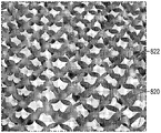
다른 이중 슬릿 패턴의 하나의 예시적인 실시 형태가 도 8a에 개략적으로 도시되어 있다. 도 8a의 패턴은, 슬릿이 행 내에서 위치 또는 형상이 변할 수 있음을 보여준다. 다시 말해서, 단일 행 내의 슬릿은 형상 및/또는 위치가 변하지만, 패턴은 인접한 행들에서 반복된다. 이러한 대체적인 개념의 구현예를 일례로 구체적으로 참조하면, 도 8a의 슬릿 패턴은, 제1 형상 및 위치와 제2 (반전된) 형상 및 위치의 슬릿(810)을 포함하는 제1 세트의 행들(812)을 포함한다. 단일 행 내의 슬릿들(810)은 제1 형상 또는 위치의 슬릿이 제2 형상 또는 위치의 슬릿 옆에 있도록 그들의 형상/위치가 교번하며, 이러한 패턴은 행을 따라 반복된다. 슬릿 형상은 반전을 제외하고는 실질적으로 동일하다.One exemplary embodiment of another double slit pattern is schematically illustrated in FIG. 8A . The pattern of FIG. 8A shows that the slits can vary in position or shape within a row. In other words, the slits within a single row change shape and/or position, but the pattern repeats in adjacent rows. Referring specifically to an implementation of this alternative concept by way of example, the slit pattern of FIG. 8A includes a first set of rows comprising a
이중 슬릿 패턴은 재료(800) 내에 형성되고, 제1 종단 단부(814), 제2 종단 단부(816) 및 중간점(818)을 각각 포함하는 복수의 슬릿(810)을 포함한다. 복수의 개별 슬릿(810)이 장력 축(T)에 대체적으로 수직인 행(812)을 형성하도록 정렬된다. 축방향 빔(820)을 형성하는 재료가 횡방향 빔(830a, 830b)의 인접한 부분들과 조합하여 행(812) 내의 인접한 슬릿들(810) 사이에 존재한다. 도 8a의 예시적인 실시 형태에서, 슬릿(810)은 (도 5a의 슬릿 패턴의 슬릿(510)과 같은) 직선이 아니라, 대신에 대체적으로 v자형 또는 커스프형이다. 슬릿(810)은, 대체적으로 장력 축(T)에 대해 45도 각도에 있고 대체적으로 사각으로 만곡된 제2 부분(823)과 연결되는 만곡된 제1 부분(821)을 포함한다. 제1 부분(821)과 제2 부분(823)은 중간점(818)에서 연결된다.The double slit pattern is formed in the
재료(800)는 슬릿(810a, 810b, 810c, 810d)을 포함한다. 슬릿(810a, 810b)은 제1 횡방향 빔(830a)의 일부분의 측부 또는 에지를 형성한다. 슬릿(810b, 810c)은 제1 중첩 빔(836a)의 일부분의 측부 또는 에지를 형성한다. 슬릿(810c, 810d)은 제2 횡방향 빔(830b)의 일부분의 측부 또는 에지를 형성한다. 제1 횡방향 빔(830a)은 제1 중첩 빔(836a) 및 제2 중첩 빔(836b)에 바로 인접한다. 제1 중첩 빔(836a) 및 제2 중첩 빔은 제2 횡방향 빔(830b)에 바로 인접한다. 제1 횡방향 빔(830a) 및 제2 횡방향 빔(830b)은 중첩 빔(836a, 836b)에 바로 인접한다. 슬릿(810a, 810b)은 서로 실질적으로 정렬된다. 슬릿(810c, 810d)은 서로 실질적으로 정렬된다. 슬릿(810b, 810c)은 서로 정렬되지 않는다. 대신에, 슬릿(810b, 810c)은 서로 위상 분리되거나 이격된다. 도 8a의 실시 형태에서, 슬릿(810)은 장력 축 (T)에 실질적으로 수직이다.
커스프형 슬릿들(810) 사이의 연속 횡방향 영역은 횡방향 빔(830)을 형성한다. 이러한 빔은 모든 2개의 인접한 행들(812, 812) 사이에서 한 번 나타난다. 중첩 빔(836a, 836b)은 행(812) 내의 인접한 슬릿들(810) 사이의 영역을 포함한다. 축방향 빔(820)이 횡방향 빔(830)의 인접한 부분들과 조합하여 단일 행(812) 내의 인접한 슬릿들(810) 사이에 존재한다.The continuous transverse region between the cusp-shaped
이러한 예시적인 실시 형태에서, 슬릿은 2개의 종단 단부를 갖는다. 직선형 가상선이 이들 종단 단부들 사이에서 연장되고 그들을 연결한다. 이러한 실시 형태에서, 제1 슬릿의 종단 단부들 사이에서 연장되고 그들을 연결하는 직선형 가상선은, 바로 인접한 슬릿의 종단 단부들 사이에서 연장되고 그들을 연결하는 직선형 가상선과 실질적으로 동일 선상에 있다. 이러한 예시적인 실시 형태에서, 단일 행 내의 슬릿 종단 단부들 사이에서 연장되고 그들을 연결하는 모든 직선형 가상선은 대략 동일 선상에 있다.In this exemplary embodiment, the slit has two terminal ends. A straight imaginary line extends between and connects these longitudinal ends. In this embodiment, the straight imaginary line extending between and connecting the terminal ends of the first slit is substantially collinear with the straight imaginary line extending between and connecting the terminal ends of immediately adjacent slits. In this exemplary embodiment, all straight imaginary lines extending between and connecting the slit terminal ends in a single row are approximately collinear.
도 8b 내지 도 8d는 장력 축(T)을 따른 장력에 노출되었을 때의, 도 8a의 슬릿 패턴을 포함하는 재료를 도시한다. 재료(800)가 장력 축(T)을 따라 장력 활성화되거나 전개될 때, 재료(800)의 일부분들은, 재료(800)가 그의 비인장된 형태에서의 재료(800)의 원래 평면 밖으로 이동하게 하는 인장 및/또는 압축을 겪는다. 장력 축을 따른 장력에 노출될 때, 종단 단부(814, 816)는 압축을 겪고 서로를 향해 당겨져, 횡방향 빔(830)의 일부분이 재료의 사전인장된 상태(도 8a)에서의 재료(800)의 원래 평면 밖으로 기복하여 루프를 형성하면서 장력 축에 공칭적으로 평행하게 유지되게 한다. 횡방향 빔(830)의 인접한 부분들과 조합된 행(812) 내의 인접한 슬릿들(810) 사이의 재료(820)는 재료의 사전인장된 상태(도 8a)에서의 재료(800)의 원래 평면에 실질적으로 평행하게 유지된다. 중첩 빔(836)은 원래 재료 또는 시트의 평면 밖으로 좌굴 및 회전한다. 횡방향 빔(830)의 기복과 조합된 중첩 빔(836)의 운동은 개방 부분(822)을 생성한다.8B-8D show the material comprising the slit pattern of FIG. 8A when exposed to tension along the tension axis T. FIG. When the
당업자는, 여전히 본 발명의 범주 내에 속하면서 패턴 및 재료에 대해 많은 변경이 이루어질 수 있다는 것을 인식할 것이다. 예를 들어, 슬릿들의 하나의 행의 종단 단부는, 슬릿들의 인접한 행의 종단 단부와 동일 선상에 있는 대신에, 슬릿들의 인접한 행의 종단 단부를 지나 이동하여, 슬릿들의 네스팅된 또는 중첩 패턴을 생성할 수 있다. 일부 실시 형태에서, 다중 슬릿 패턴은 이중 슬릿 패턴 대신에 삼중 슬릿, 사중 슬릿, 또는 다른 다중 슬릿일 것이다. 대안적으로, 슬릿 길이, 슬릿 크기, 슬릿 두께, 슬릿 형상, 행 크기 또는 형상, 횡방향 빔 크기 또는 형상, 및/또는 중첩 빔 크기 또는 형상이 달라질 수 있다. 도 8a에 도시된 곡률의 정도 및 슬릿 길이는 달라질 수 있다. 추가로, 오프셋 또는 위상 오프셋의 정도가 도시된 것과는 다를 수 있다. 슬릿, 행, 또는 빔 피치가 달라질 수 있다. 추가로, 패턴은 2개의 행, 3개의 행, 4개의 행 등에서 교번할 수 있다. 장력 축과 슬릿 사이의 각도가 달라질 수 있다. 이들 변경들 중 많은 것이 전개 패턴을 변경할 수 있다.Those skilled in the art will recognize that many changes can be made to the pattern and material while still falling within the scope of the present invention. For example, the terminal end of one row of slits, instead of being collinear with the terminal end of an adjacent row of slits, moves past the terminal end of an adjacent row of slits to create a nested or overlapping pattern of slits. can create In some embodiments, the multiple slit pattern will be triple slits, quadruple slits, or other multiple slits instead of double slit patterns. Alternatively, the slit length, slit size, slit thickness, slit shape, row size or shape, transverse beam size or shape, and/or overlapping beam size or shape may vary. The degree of curvature and the slit length shown in FIG. 8A may vary. Additionally, the degree of offset or phase offset may be different from that shown. The slit, row, or beam pitch may vary. Additionally, the pattern may alternate in 2 rows, 3 rows, 4 rows, and the like. The angle between the tension axis and the slit may vary. Many of these changes can change the deployment pattern.
장력 활성화식 재료(800)가 물품 주위에 래핑되거나 그 자체에 바로 인접하게 배치될 때, 루프 및 기복부는 서로 그리고/또는 개방 부분(822)과 상호로킹되어 상호로킹 구조물을 생성한다. 상호로킹은 위에서 설명된 상호로킹 시험에서 언급된 바와 같이 측정될 수 있다.When the tension-activated
슬릿이 선형 슬릿인 것 대신에 향상된 상호로킹 구조물 또는 특징부를 포함하는 것을 제외하고는 도 5a에 도시된 것과 유사한 이중 슬릿 패턴을 포함하는 재료의 개략 평면도인 도 9a에 이중 슬릿 패턴의 다른 예가 도시되어 있다. 더 구체적으로, 재료(900)는 슬릿(910a, 910b, 910c, 910d)을 포함한다. 슬릿(910a, 910b)은 제1 횡방향 빔(930a)의 일부분의 측부 또는 에지를 형성한다. 슬릿(910b, 910c)은 중첩 빔(936)의 일부분의 측부 또는 에지를 형성한다. 슬릿(910c, 910d)은 제2 횡방향 빔(930b)의 일부분의 측부 또는 에지를 형성한다. 제1 횡방향 빔(930a)이 중첩 빔(936)에 바로 인접한다. 중첩 빔(936)은 제2 횡방향 빔(930b)에 바로 인접한다. 슬릿(910a, 910b)은 서로 실질적으로 정렬된다. 슬릿(910c, 910d)은 서로 실질적으로 정렬된다. 슬릿(910b, 910c)은 서로 정렬되지 않는다. 대신에, 슬릿(910b, 910c)은 서로 위상 분리되거나 이격된다. 도 9a의 실시 형태에서, 슬릿(910)은 장력 축(T)에 실질적으로 수직이다. 도 9a의 특정 실시 형태에서, 슬릿(910)은 슬릿(910)의 상부 부분 및 슬릿(910)의 하부 부분에 직사각형 후크를 포함하거나 형성한다. 이들 구형파 후크 특징부 - 및 그들을 슬릿의 상부 부분 및 하부 부분 둘 모두에 포함하는 것 - 는 우수한 상호로킹을 가져올 수 있다. 이들 특징부는, 또한, 상부 부분 또는 하부 부분 중 하나에만 포함되면서 여전히 우수한 상호로킹을 제공할 수 있다.Another example of a double slit pattern is shown in FIG. 9A, which is a schematic plan view of a material comprising a double slit pattern similar to that shown in FIG. 5A except that the slits include improved interlocking structures or features instead of being linear slits. have. More specifically, material 900 includes
추가로, 이러한 예시적인 실시 형태에서, 슬릿은 2개의 종단 단부를 갖는다. 직선형 가상선이 이들 종단 단부들 사이에서 연장되고 그들을 연결한다. 이러한 실시 형태에서, 제1 슬릿의 종단 단부들 사이에서 연장되고 그들을 연결하는 직선형 가상선은, 바로 인접한 슬릿의 종단 단부들 사이에서 연장되고 그들을 연결하는 직선형 가상선과 실질적으로 동일 선상에 있다. 이러한 예시적인 실시 형태에서, 행 내의 슬릿 종단 단부들 사이에서 연장되고 그들을 연결하는 모든 직선형 가상선은 대략 동일 선상에 있다. 슬릿의 단부는 만곡된다.Additionally, in this exemplary embodiment, the slit has two terminal ends. A straight imaginary line extends between and connects these longitudinal ends. In this embodiment, the straight imaginary line extending between and connecting the terminal ends of the first slit is substantially collinear with the straight imaginary line extending between and connecting the terminal ends of immediately adjacent slits. In this exemplary embodiment, all straight imaginary lines extending between and connecting the slit terminal ends in a row are approximately collinear. The end of the slit is curved.
도 9b 내지 도 9d는 장력 축(T)을 따른 장력에 노출되었을 때의, 도 9a의 슬릿 패턴을 포함하는 재료의 사진이다. 재료(900)가 장력 축(T)을 따라 장력 활성화되거나 전개될 때, 재료(900)의 일부분들은, 재료(900)가 그의 비인장된 형태에서의 재료(900)의 원래 평면 밖으로 이동하게 하는 인장 및/또는 압축을 겪는다. 장력 축을 따른 장력에 노출될 때, 종단 단부(914, 916)는 압축을 겪고 서로를 향해 당겨진다. 횡방향 빔(930)의 일부분들은 재료의 사전인장된 상태(도 9a)에서의 재료(900)의 원래 평면 밖으로 기복하여 루프를 형성하면서, 장력 축에 공칭적으로 평행하게 유지된다. 횡방향 빔(930)의 인접한 부분들과 조합된 행(912) 내의 인접한 슬릿들(910) 사이의 축방향 빔(920)을 형성하는 재료는 재료의 사전인장된 상태(도 9a)에서의 재료(900)의 원래 평면에 실질적으로 평행하게 유지된다. 중첩 빔(936)은 원래 재료 또는 시트의 평면 밖으로 좌굴 및 회전한다. 횡방향 빔(930)의 기복과 조합된 중첩 빔(936)의 운동은 개방 부분(922)을 생성한다.9B-9D are photographs of the material comprising the slit pattern of FIG. 9A when exposed to tension along the tension axis T; When the material 900 is tension activated or unfolded along the tension axis T, portions of the material 900 cause the material 900 to move out of the original plane of the material 900 in its untensioned form. undergo tension and/or compression. When exposed to tension along the tension axis, the terminal ends 914 and 916 undergo compression and are pulled towards each other. Portions of
당업자는, 여전히 본 발명의 범주 내에 속하면서 패턴 및 재료에 대해 많은 변경이 이루어질 수 있다는 것을 인식할 것이다. 예를 들어, 일부 실시 형태에서, 다중 슬릿 패턴은 이중 슬릿 패턴 대신에 삼중 슬릿, 사중 슬릿, 또는 다른 다중 슬릿일 것이다. 대안적으로, 슬릿 길이, 슬릿 크기, 슬릿 두께, 슬릿 형상, 행 크기 또는 형상, 횡방향 빔 크기 또는 형상, 및/또는 중첩 빔 크기 또는 형상이 달라질 수 있다. 추가로, 오프셋 또는 위상 오프셋의 정도가 도시된 것과는 다를 수 있다. 슬릿, 행, 또는 빔 피치가 달라질 수 있다. 장력 축과 슬릿 사이의 각도가 달라질 수 있다. 이들 변경들 중 많은 것이 전개 패턴을 변경할 수 있다.Those skilled in the art will recognize that many changes can be made to the pattern and material while still falling within the scope of the present invention. For example, in some embodiments, the multiple slit pattern will be a triple slit, a quadruple slit, or other multiple slits instead of a double slit pattern. Alternatively, the slit length, slit size, slit thickness, slit shape, row size or shape, transverse beam size or shape, and/or overlapping beam size or shape may vary. Additionally, the degree of offset or phase offset may be different from that shown. The slit, row, or beam pitch may vary. The angle between the tension axis and the slit may vary. Many of these changes can change the deployment pattern.
장력 활성화식 재료(900)가 물품 주위에 래핑되거나 그 자체에 바로 인접하게 배치될 때, 플랩, 루프 및 기복부는 서로 그리고/또는 개방 부분(922)과 상호로킹되어 상호로킹 구조물을 생성한다. 상호로킹은 위에서 설명된 상호로킹 시험에서 언급된 바와 같이 측정될 수 있다.When the tension-activated material 900 is wrapped around an article or placed immediately adjacent to itself, the flaps, loops and reliefs interlock with each other and/or with the
슬릿이 선형 슬릿인 것 대신에 향상된 상호로킹 구조물 또는 특징부를 포함하는 것을 제외하고는 도 5a에 도시된 것과 유사한 이중 슬릿 패턴을 포함하는 재료의 개략 평면도인 도 10a 및 도 10b에 이중 슬릿 패턴의 다른 예가 도시되어 있다. 더 구체적으로, 재료(1000)는 슬릿(1010a, 1010b, 1010c, 1010d)을 포함한다. 슬릿(1010a, 1010b)은 제1 횡방향 빔(1030a)의 일부분의 측부 또는 에지를 형성한다. 슬릿(1010b, 1010c)은 중첩 빔(1036)의 일부분의 측부 또는 에지를 형성한다. 슬릿(1010c, 1010d)은 제2 횡방향 빔(1030b)의 일부분의 측부 또는 에지를 형성한다. 제1 횡방향 빔(1030a)이 중첩 빔(1036)에 바로 인접한다. 중첩 빔(1036)은 제2 횡방향 빔(1030b)에 바로 인접한다. 슬릿(1010a, 1010b)은 서로 실질적으로 정렬된다. 슬릿(1010c, 1010d)은 서로 실질적으로 정렬된다. 슬릿(1010b, 1010c)은 서로 정렬되지 않는다. 대신에, 슬릿(1010b, 1010c)은 서로 위상 분리되거나 이격된다. 도 10a의 실시 형태에서, 슬릿(1010)은 장력 축(T)에 실질적으로 수직이다. 도 10a의 특정 실시 형태에서, 슬릿(1010)은 슬릿(1010)의 상부 부분 및 슬릿(1010)의 하부 부분에 앵커형(anchor-shaped) 후크를 포함하거나 형성한다. 이들 앵커형 후크 특징부 - 및 그들을 슬릿의 상부 부분 및 하부 부분 둘 모두에 포함하는 것 - 는 우수한 상호로킹을 가져올 수 있다. 이들 특징부는, 또한, 상부 부분 또는 하부 부분 중 하나에만 포함되면서 여전히 우수한 상호로킹을 제공할 수 있다.Another example of a double slit pattern is shown in FIGS. 10A and 10B , which are schematic top views of a material comprising a double slit pattern similar to that shown in FIG. 5A except that the slits include improved interlocking structures or features instead of being linear slits. An example is shown. More specifically,
추가로, 이러한 예시적인 실시 형태에서, 슬릿은 2개의 종단 단부를 갖는다. 직선형 가상선이 이들 종단 단부들 사이에서 연장되고 그들을 연결한다. 이러한 실시 형태에서, 제1 슬릿의 종단 단부들 사이에서 연장되고 그들을 연결하는 직선형 가상선은, 바로 인접한 슬릿의 종단 단부들 사이에서 연장되고 그들을 연결하는 직선형 가상선과 실질적으로 동일 선상에 있다. 이러한 예시적인 실시 형태에서, 행 내의 슬릿 종단 단부들 사이에서 연장되고 그들을 연결하는 모든 직선형 가상선은 대략 동일 선상에 있다. 슬릿의 단부는 만곡된다.Additionally, in this exemplary embodiment, the slit has two terminal ends. A straight imaginary line extends between and connects these longitudinal ends. In this embodiment, the straight imaginary line extending between and connecting the terminal ends of the first slit is substantially collinear with the straight imaginary line extending between and connecting the terminal ends of immediately adjacent slits. In this exemplary embodiment, all straight imaginary lines extending between and connecting the slit terminal ends in a row are approximately collinear. The end of the slit is curved.
도 10c 내지 도 10e는 장력 축(T)을 따른 장력에 노출되었을 때의, 도 10a의 슬릿 패턴을 포함하는 재료의 사진이다. 재료(1000)가 장력 축(T)을 따라 장력 활성화되거나 전개될 때, 재료(1000)의 일부분들은, 재료(1000)가 그의 비인장된 형태에서의 재료(1000)의 원래 평면 밖으로 이동하게 하는 인장 및/또는 압축을 겪는다. 장력 축을 따른 장력에 노출될 때, 종단 단부(1014, 1016)는 압축을 겪고 서로를 향해 당겨진다. 횡방향 빔(1030)의 일부분들은 재료의 사전인장된 상태(도 10a)에서의 재료(1000)의 원래 평면 밖으로 기복하여 루프를 형성하면서, 장력 축에 공칭적으로 평행하게 유지된다. 횡방향 빔(1030)의 인접한 부분들과 조합된 행(1012) 내의 인접한 슬릿들(1010) 사이의 축방향 빔(1020)이 재료의 사전인장된 상태(도 10a)에서의 재료(1000)의 원래 평면에 실질적으로 평행하게 유지된다. 중첩 빔(1036)은 원래 재료 또는 시트의 평면 밖으로 좌굴 및 회전한다. 횡방향 빔(1030)의 기복과 조합된 중첩 빔(1036)의 운동은 개방 부분(1022)을 생성한다.10C-10E are photographs of material comprising the slit pattern of FIG. 10A when exposed to tension along the tension axis T; When the
당업자는, 여전히 본 발명의 범주 내에 속하면서 패턴 및 재료에 대해 많은 변경이 이루어질 수 있다는 것을 인식할 것이다. 예를 들어, 일부 실시 형태에서, 다중 슬릿 패턴은 이중 슬릿 패턴 대신에 삼중 슬릿, 사중 슬릿, 또는 다른 다중 슬릿일 것이다. 대안적으로, 슬릿 길이, 슬릿 크기, 슬릿 두께, 슬릿 형상, 행 크기 또는 형상, 횡방향 빔 크기 또는 형상, 및/또는 중첩 빔 크기 또는 형상이 달라질 수 있다. 추가로, 오프셋 또는 위상 오프셋의 정도가 도시된 것과는 다를 수 있다. 슬릿, 행, 또는 빔 피치가 달라질 수 있다. 장력 축과 슬릿 사이의 각도가 달라질 수 있다. 이들 변경들 중 많은 것이 전개 패턴을 변경할 수 있다.Those skilled in the art will recognize that many changes can be made to the pattern and material while still falling within the scope of the present invention. For example, in some embodiments, the multiple slit pattern will be a triple slit, a quadruple slit, or other multiple slits instead of a double slit pattern. Alternatively, the slit length, slit size, slit thickness, slit shape, row size or shape, transverse beam size or shape, and/or overlapping beam size or shape may vary. Additionally, the degree of offset or phase offset may be different from that shown. The slit, row, or beam pitch may vary. The angle between the tension axis and the slit may vary. Many of these changes can change the deployment pattern.
장력 활성화식 재료(1000)가 물품 주위에 래핑되거나 그 자체에 바로 인접하게 배치될 때, 플랩, 루프 및 기복부는 서로 그리고/또는 개방 부분(1022)과 상호로킹되어 상호로킹 구조물을 생성한다. 상호로킹은 위에서 설명된 상호로킹 시험에서 언급된 바와 같이 측정될 수 있다.When the tension-activated
슬릿이 다중빔 슬릿을 포함하는 것을 제외하고는 도 5a에 도시된 것과 유사한 이중 슬릿 패턴을 포함하는 재료의 개략 평면도인 도 11a에 이중 슬릿 패턴의 다른 예가 도시되어 있다. "다중빔 슬릿"은 단일 슬릿 또는 다중 슬릿 패턴에서 2개의 인접한 슬릿들 사이에 형성된 하나 이상의 단순 슬릿(슬릿이 2개 이하의 종단 단부를 가짐을 의미함)으로 정의되며, 여기에서 2개의 인접한 슬릿들은 동일한 행 또는 인접한 행들 내에 있다. 빔 영역, 및 더 구체적으로는 도 11a의 단부(1116a, 1114a)와 같은 인접한 행들 내의 2개의 인접한 슬릿들의 가장 가까운 종단 단부들 사이의 직접 경로는, 단일 슬릿 패턴화된 재료에 장력이 인가될 때 가장 높은 힘의 집중을 겪는다. 이와 같이, 이들 빔 영역은 재료의 전개(또는 장력 인가 또는 활성화) 동안 가장 큰 응력 집중을 겪는다. 이러한 높은 응력 집중은 전개 동안 재료의 인열을 초래할 수 있다. 인접한 행들 내의 가장 가까운 종단 단부들 사이의 직접 경로를 통해 가로지르는, 이러한 영역에 추가된 추가 슬릿은, 재료의 최대 힘 지지 용량을 증가시킬 수 있는 추가 응력 집중 종단 단부를 갖는 하나 이상의 추가 힘 전달 경로 또는 추가 빔을 생성할 수 있다. 다중빔 슬릿 패턴을 포함하는 재료 또는 물품은, 동일한 패턴의 빔들을 갖지만 다중빔이 없는 재료 또는 물품과 비교하여 더 큰 최대 장력을 갖는다. 본 명세서에서 사용되는 바와 같이, 용어 "최대 장력"은, 슬릿 패턴화된 재료의 샘플이 인열되기 전에 그에 인가될 수 있는 최대 인장력을 지칭한다. 대체적으로, 최대 장력은 슬릿 패턴화된 재료가 인열되기 직전에 발생한다. 최대 장력을 측정하기 위한 시험 방법은, 그 전체가 본 명세서에 참고로 포함되는, 본 양수인에게 양도된 미국 특허 출원 제62/953042호에 기재되어 있다. 최대 장력(예컨대, 인열력)은, 샘플이 신장됨에 따라 로드 셀에 의해 측정되는 최대 힘이다. 이는, 전형적으로, 재료가 인열되기 시작하기 직전이다. 일부 실시 형태에서, 다중빔 슬릿 패턴을 포함하는 재료 또는 물품은, 다중빔이 없는 것을 제외하고는 동일한 패턴을 갖는 재료 또는 물품과 비교하여 인열 없이 더 큰 장력을 견딜 수 있다.Another example of a double slit pattern is shown in FIG. 11A , which is a schematic plan view of a material comprising a double slit pattern similar to that shown in FIG. 5A except that the slit includes a multibeam slit. "Multibeam slit" is defined as one or more simple slits formed between two adjacent slits in a single slit or multiple slit pattern, meaning the slit has no more than two terminal ends, wherein two adjacent slits are in the same row or adjacent rows. A direct path between the beam region, and more specifically the nearest terminating ends of two adjacent slits in adjacent rows, such as
일부 실시 형태에서, 다중빔 슬릿 패턴을 갖는 재료 또는 물품은 동일하거나 더 낮은 전개력을 갖는다. 본 명세서에서 사용되는 바와 같이, 용어 "전개력"은 패턴화된 시트를 실질적으로 전개하는 데 필요한 힘을 지칭한다.In some embodiments, a material or article having a multibeam slit pattern has the same or lower deployment force. As used herein, the term “unfolding force” refers to the force required to substantially unfold a patterned sheet.
일부 실시 형태에서, 최대 장력(장력 축(T)을 따른 전개 또는 인장 동안 슬릿 패턴화된 재료를 인열하는 데 필요한 장력)을 전개력(샘플을 전개하는 데 필요한 힘)보다 크게 하는 것이 유리하다. Max-Deploy Ratio는 최대 장력을 전개력으로 나눈 비이다. 일부 실시 형태에서, 그 비는 패턴화된 시트를 전개하기 위해 인가되는 힘이 시트가 견딜 수 있는 최대 힘보다 훨씬 더 낮도록 가능한 한 큰 것이 유리하다. 이는, 시트의 사용자가 재료를 전개할 때 그를 우발적으로 인열하는 것을 방지한다.In some embodiments, it is advantageous to have the maximum tension (the tension required to tear the slit patterned material during deployment or tensioning along the tension axis T) greater than the deployment force (the force needed to unfold the sample). Max-Deploy Ratio is the ratio of the maximum tension divided by the deployment force. In some embodiments, it is advantageous for the ratio to be as large as possible so that the force applied to unfold the patterned sheet is much lower than the maximum force that the sheet can withstand. This prevents the user of the sheet from accidentally tearing the material as it unfolds.
도 11a는 도 11a의 실시예가 다중빔을 포함하는 것을 제외하고는 도 5a에 도시된 실시예와 실질적으로 동일하기 때문에, 도 5a의 설명이 여기에서 반복된다. 다중빔 슬릿(1180)(이 실시 형태에서, 2개의 다중빔 슬릿)이 중첩 빔(1136) 내에 형성된다. 이들 다중빔 슬릿(1180)은, 재료(1100)가 장력 축을 따른 장력에 노출될 때 다중빔의 형성을 가능하게 할 것이다. 도 11a의 다중빔 슬릿(1180) 및 생성된 다중빔은 실질적으로 선형이다.Since FIG. 11A is substantially identical to the embodiment shown in FIG. 5A except that the embodiment of FIG. 11A includes multiple beams, the description of FIG. 5A is repeated here. A multibeam slit 1180 (in this embodiment, two multibeam slits) is formed in the overlapping
당업자는, 여전히 본 발명의 범주 내에 속하면서 패턴에 대해 많은 변경이 이루어질 수 있다는 것을 인식할 것이다. 일부 실시 형태에서, 다중 슬릿 패턴은 이중 슬릿 패턴 대신에 삼중 슬릿, 사중 슬릿, 또는 다른 다중 슬릿일 것이다. 대안적으로, 슬릿 길이, 슬릿 크기, 슬릿 두께, 슬릿 형상, 행 크기 또는 형상, 횡방향 빔 크기 또는 형상, 및/또는 중첩 빔 크기 또는 형상이 달라질 수 있다. 추가로, 오프셋 또는 위상 오프셋의 정도가 도시된 것과는 다를 수 있다. 슬릿, 행, 또는 빔 피치가 달라질 수 있다. 장력 축과 슬릿 사이의 각도가 달라질 수 있다. 다중빔 슬릿 및/또는 다중빔의 수, 형상, 크기 등이 달라질 수 있다. 대안적으로, 행 크기 또는 형상 및 빔 크기 또는 형상이 달라질 수 있다. 추가로, 오프셋 또는 위상 오프셋의 정도가 도시된 것과는 다를 수 있다. 이들 변경들 중 많은 것이 전개 패턴을 변경할 수 있다.Those skilled in the art will recognize that many changes can be made to the pattern while still falling within the scope of the present invention. In some embodiments, the multiple slit pattern will be triple slits, quadruple slits, or other multiple slits instead of double slit patterns. Alternatively, the slit length, slit size, slit thickness, slit shape, row size or shape, transverse beam size or shape, and/or overlapping beam size or shape may vary. Additionally, the degree of offset or phase offset may be different from that shown. The slit, row, or beam pitch may vary. The angle between the tension axis and the slit may vary. The number, shape, size, etc. of the multi-beam slits and/or multi-beams may vary. Alternatively, the row size or shape and the beam size or shape may vary. Additionally, the degree of offset or phase offset may be different from that shown. Many of these changes can change the deployment pattern.
도 11b는 장력 축(T)을 따른 장력에 노출되었을 때의, 도 11a의 슬릿 패턴을 포함하는 재료의 도면이다. 재료(1100)가 장력 축(T)을 따라 장력 활성화되거나 전개될 때, 재료(1100)의 일부분들은, 재료(1100)가 그의 비인장된 형태에서의 재료(1100)의 원래 평면 밖으로 이동하게 하는 인장 및/또는 압축을 겪는다. 횡방향 빔(1130)의 일부분들은 재료의 사전인장된 상태(도 11a)에서의 재료(1100)의 원래 평면 밖으로 기복하여 루프를 형성하면서, 장력 축에 공칭적으로 평행하게 유지된다. 횡방향 빔(1130)의 인접한 부분들과 조합된 행(1112) 내의 인접한 슬릿들(1110) 사이의 축방향 빔(1120)은 재료의 사전인장된 상태(도 11a)에서의 재료(1100)의 원래 평면에 실질적으로 평행하게 유지된다. 중첩 빔(1136)은 원래 재료 또는 시트의 평면 밖으로 좌굴 및 회전한다. 2개의 다중빔 슬릿(1180)의 추가 때문에, 각각의 중첩 빔(1136)은, 각각 장력을 전달하고 서로 공칭적으로 평행하게 유지되며 그룹으로서 이동 또는 회전하는 3개의 별개의 다중빔(1182)으로 커팅된다. 횡방향 빔(1130)의 기복과 조합된 중첩 빔(1136)의 운동은 개방 부분(1122)을 생성한다. 이와 같이, 재료(1100)는, 다중빔(1182)이 형성되는 것을 제외하고는, 실질적으로 도 5a의 패턴과 관련하여 설명된 바와 같이 전개된다.FIG. 11B is a diagram of the material comprising the slit pattern of FIG. 11A when exposed to tension along the tension axis T. FIG. When the
장력 활성화식 재료(1100)가 물품 주위에 래핑되거나 그 자체에 바로 인접하게 배치될 때, 루프 및 기복부는 서로 그리고/또는 개방 부분(1122)과 상호로킹되어 상호로킹 구조물을 생성한다. 상호로킹은 위에서 설명된 상호로킹 시험에서 언급된 바와 같이 측정될 수 있다.When the tension-activated
다중빔을 포함하는 슬릿 패턴의 예시적인 실시 형태가 도 12a 내지 도 12e에 도시되어 있다. 도 12a는, 도 12a의 실시예가 다중빔을 포함하는 것을 제외하고는 도 8a에 도시된 실시 형태와 실질적으로 동일하다. 이와 같이, 도 8a의 설명이 여기에서 반복된다. 도 12b는 도 12a의 확대된 부분이다. 다중빔 슬릿(1280)(이 실시 형태에서, 하나의 다중빔 슬릿)이 중첩 빔(836) 내에 형성된다. 이들 다중빔 슬릿(1280)은, 재료(1200)가 장력 축을 따른 장력에 노출될 때 다중빔의 형성을 가능하게 할 것이다. 도 12a의 다중빔 슬릿(1280) 및 생성된 다중빔은, 슬릿(810)의 곡률을 따르거나 모사하도록 만곡된다.Exemplary embodiments of slit patterns comprising multiple beams are shown in FIGS. 12A-12E . FIG. 12A is substantially the same as the embodiment shown in FIG. 8A except that the embodiment of FIG. 12A includes multiple beams. As such, the description of FIG. 8A is repeated here. Figure 12b is an enlarged portion of Figure 12a. A multibeam slit 1280 (in this embodiment, one multibeam slit) is formed in the overlapping
당업자는, 여전히 본 발명의 범주 내에 속하면서 패턴에 대해 많은 변경이 이루어질 수 있다는 것을 인식할 것이다. 일부 실시 형태에서, 다중 슬릿 패턴은 이중 슬릿 패턴 대신에 삼중 슬릿, 사중 슬릿, 또는 다른 다중 슬릿일 것이다. 대안적으로, 슬릿 길이, 슬릿 크기, 슬릿 두께, 슬릿 형상, 행 크기 또는 형상, 횡방향 빔 크기 또는 형상, 및/또는 중첩 빔 크기 또는 형상이 달라질 수 있다. 추가로, 오프셋 또는 위상 오프셋의 정도가 도시된 것과는 다를 수 있다. 슬릿, 행, 또는 빔 피치가 달라질 수 있다. 장력 축과 슬릿 사이의 각도가 달라질 수 있다. 다중빔 슬릿 및/또는 다중빔의 수, 형상, 크기 등이 달라질 수 있다. 대안적으로, 행 크기 또는 형상 및 빔 크기 또는 형상이 달라질 수 있다. 추가로, 오프셋 또는 위상 오프셋의 정도가 도시된 것과는 다를 수 있다. 이들 변경들 중 많은 것이 전개 패턴을 변경할 수 있다.Those skilled in the art will recognize that many changes can be made to the pattern while still falling within the scope of the present invention. In some embodiments, the multiple slit pattern will be triple slits, quadruple slits, or other multiple slits instead of double slit patterns. Alternatively, the slit length, slit size, slit thickness, slit shape, row size or shape, transverse beam size or shape, and/or overlapping beam size or shape may vary. Additionally, the degree of offset or phase offset may be different from that shown. The slit, row, or beam pitch may vary. The angle between the tension axis and the slit may vary. The number, shape, size, etc. of the multi-beam slits and/or multi-beams may vary. Alternatively, the row size or shape and the beam size or shape may vary. Additionally, the degree of offset or phase offset may be different from that shown. Many of these changes can change the deployment pattern.
도 12c 내지 도 12e는 장력 축(T)을 따른 장력에 노출되었을 때의, 도 12a 및 도 12b의 슬릿 패턴을 포함하는 재료를 도시한다. 재료는, 다중빔(1282)이 형성되는 것을 제외하고는, 실질적으로 도 8a의 패턴과 관련하여 설명된 바와 같이 전개된다.12C-12E show the material comprising the slit pattern of FIGS. 12A and 12B when exposed to tension along the tension axis T. FIGS. The material is developed substantially as described with respect to the pattern of FIG. 8A, except that a multibeam 1282 is formed.
장력 활성화식 재료(1200)가 물품 주위에 래핑되거나 그 자체에 바로 인접하게 배치될 때, 플랩, 루프 및 기복부는 서로 그리고/또는 개방 부분(1222)과 상호로킹되어 상호로킹 구조물을 생성한다. 상호로킹은 위에서 설명된 상호로킹 시험에서 언급된 바와 같이 측정될 수 있다.When the tension-activated
만곡된 단부를 포함하는 슬릿 패턴의 예시적인 실시 형태가 도 13a 내지 도 13d에 도시되어 있다. 도 13a는, 슬릿(510)의 종단 단부가 만곡된 것 - 이는 슬릿의 종단 단부를 형성하는 슬릿의 단부 영역이 슬릿의 인접한 부분과 구별되는 곡률 반경을 갖는다는 것을 의미함 - 을 제외하고는 도 5a에 도시된 실시 형태와 실질적으로 동일하다. 단부 영역은, 대체적으로 슬릿의 총 길이의 10% 미만인 길이를 갖는다. 이와 같이, 도 5a의 설명이 여기에서 반복된다.Exemplary embodiments of slit patterns including curved ends are shown in FIGS. 13A-13D . 13A is a diagram except that the terminal end of the
당업자는, 여전히 본 발명의 범주 내에 속하면서 패턴에 대해 많은 변경이 이루어질 수 있다는 것을 인식할 것이다. 일부 실시 형태에서, 다중 슬릿 패턴은 이중 슬릿 패턴 대신에 삼중 슬릿, 사중 슬릿, 또는 다른 다중 슬릿일 것이다. 대안적으로, 슬릿 길이, 슬릿 크기, 슬릿 두께, 슬릿 형상, 행 크기 또는 형상, 횡방향 빔 크기 또는 형상, 및/또는 중첩 빔 크기 또는 형상이 달라질 수 있다. 추가로, 오프셋 또는 위상 오프셋의 정도가 도시된 것과는 다를 수 있다. 슬릿, 행, 또는 빔 피치가 달라질 수 있다. 장력 축과 슬릿 사이의 각도가 달라질 수 있다. 종단 단부의 곡률의 정도가 달라질 수 있다. 대안적으로, 행 크기 또는 형상 및 빔 크기 또는 형상이 달라질 수 있다. 추가로, 오프셋 또는 위상 오프셋의 정도가 도시된 것과는 다를 수 있다. 이들 변경들 중 많은 것이 전개 패턴을 변경할 수 있다.Those skilled in the art will recognize that many changes can be made to the pattern while still falling within the scope of the present invention. In some embodiments, the multiple slit pattern will be triple slits, quadruple slits, or other multiple slits instead of double slit patterns. Alternatively, the slit length, slit size, slit thickness, slit shape, row size or shape, transverse beam size or shape, and/or overlapping beam size or shape may vary. Additionally, the degree of offset or phase offset may be different from that shown. The slit, row, or beam pitch may vary. The angle between the tension axis and the slit may vary. The degree of curvature of the longitudinal end may vary. Alternatively, the row size or shape and the beam size or shape may vary. Additionally, the degree of offset or phase offset may be different from that shown. Many of these changes can change the deployment pattern.
도 13b 내지 도 13d는 장력 축(T)을 따른 장력에 노출되었을 때의, 도 13a의 슬릿 패턴을 포함하는 재료의 사진 및 사진으로부터의 도면이다. 재료는, 실질적으로 도 5a의 패턴과 관련하여 설명된 바와 같이 전개된다. 슬릿(1310)의 만곡된 단부는, 재료가 인열 없이 겪을 수 있는 최대 장력을 증가시킨다.13B-13D are photographs and diagrams from photographs of the material comprising the slit pattern of FIG. 13A when exposed to tension along the tension axis T; The material is developed substantially as described with respect to the pattern of FIG. 5A . The curved end of the slit 1310 increases the maximum tension the material can undergo without tearing.
장력 활성화식 재료(1300)가 물품 주위에 래핑되거나 그 자체에 바로 인접하게 배치될 때, 플랩, 루프 및 기복부는 서로 그리고/또는 개방 부분(522)과 상호로킹되어 상호로킹 구조물을 생성한다. 상호로킹은 위에서 설명된 상호로킹 시험에서 언급된 바와 같이 측정될 수 있다.When the tension-activated
만곡된 에지를 포함하는 슬릿 패턴의 예시적인 실시 형태가 도 14a 내지 도 14c에 도시되어 있다. 도 14a는, 슬릿(1410)의 종단 단부가 만곡된 것을 제외하고는 도 5a에 도시된 실시 형태와 실질적으로 동일하다. 이와 같이, 도 5a의 설명이 여기에서 반복된다.Exemplary embodiments of slit patterns including curved edges are shown in FIGS. 14A-14C . FIG. 14A is substantially the same as the embodiment shown in FIG. 5A except that the terminal end of the slit 1410 is curved. As such, the description of FIG. 5A is repeated here.
당업자는, 여전히 본 발명의 범주 내에 속하면서 패턴에 대해 많은 변경이 이루어질 수 있다는 것을 인식할 것이다. 일부 실시 형태에서, 다중 슬릿 패턴은 이중 슬릿 패턴 대신에 삼중 슬릿, 사중 슬릿, 또는 다른 다중 슬릿일 것이다. 대안적으로, 슬릿 길이, 슬릿 크기, 슬릿 두께, 슬릿 형상, 행 크기 또는 형상, 횡방향 빔 크기 또는 형상, 및/또는 중첩 빔 크기 또는 형상이 달라질 수 있다. 추가로, 오프셋 또는 위상 오프셋의 정도가 도시된 것과는 다를 수 있다. 슬릿, 행, 또는 빔 피치가 달라질 수 있다. 장력 축과 슬릿 사이의 각도가 달라질 수 있다. 종단 단부의 곡률의 정도가 달라질 수 있다. 대안적으로, 행 크기 또는 형상 및 빔 크기 또는 형상이 달라질 수 있다. 추가로, 오프셋 또는 위상 오프셋의 정도가 도시된 것과는 다를 수 있다. 이들 변경들 중 많은 것이 전개 패턴을 변경할 수 있다.Those skilled in the art will recognize that many changes can be made to the pattern while still falling within the scope of the present invention. In some embodiments, the multiple slit pattern will be triple slits, quadruple slits, or other multiple slits instead of double slit patterns. Alternatively, the slit length, slit size, slit thickness, slit shape, row size or shape, transverse beam size or shape, and/or overlapping beam size or shape may vary. Additionally, the degree of offset or phase offset may be different from that shown. The slit, row, or beam pitch may vary. The angle between the tension axis and the slit may vary. The degree of curvature of the longitudinal end may vary. Alternatively, the row size or shape and the beam size or shape may vary. Additionally, the degree of offset or phase offset may be different from that shown. Many of these changes can change the deployment pattern.
도 14b 및 도 14c는 장력 축(T)을 따른 장력에 노출되었을 때의, 도 14a의 슬릿 패턴을 포함하는 재료의 사진이다. 재료는, 실질적으로 도 5a의 패턴과 관련하여 설명된 바와 같이 전개된다. 슬릿(1410)의 만곡된 단부는, 재료가 인열 없이 겪을 수 있는 최대 장력을 증가시킨다.14B and 14C are photographs of the material comprising the slit pattern of FIG. 14A when exposed to tension along the tension axis T; The material is developed substantially as described with respect to the pattern of FIG. 5A . The curved end of the slit 1410 increases the maximum tension the material can undergo without tearing.
장력 활성화식 재료(1400)가 물품 주위에 래핑되거나 그 자체에 바로 인접하게 배치될 때, 플랩, 루프 및 기복부는 서로 그리고/또는 개방 부분(522)과 상호로킹되어 상호로킹 구조물을 생성한다. 상호로킹은 위에서 설명된 상호로킹 시험에서 언급된 바와 같이 측정될 수 있다.When the tension-activated
상호로킹 특징부 및 다중빔을 포함하는 슬릿 패턴의 예시적인 실시 형태가 도 15a 및 도 15b에 도시되어 있다. 도 15a는, 패턴이 중첩 빔(1036)에 다중빔 슬릿(1580)을 포함하는 것을 제외하고는 도 10a에 도시된 실시 형태와 실질적으로 동일하다. 이와 같이, 도 10a의 설명이 여기에서 반복된다. 도 15b는 도 15a의 확대된 섹션을 도시한다. 재료는, 도 15a의 슬릿 패턴을 포함하는 재료가 장력 축을 따른 장력에 노출될 때 다중빔 슬릿이 다중빔을 생성하는 것을 제외하고는, 실질적으로 도 10a의 패턴과 관련하여 설명된 바와 같이 전개된다. 다중빔들은 재료가 인열 없이 겪을 수 있는 최대 장력을 증가시키고, 그들은, 또한, 재료를 전개하는 데 필요한 장력의 양을 감소시킨다.Exemplary embodiments of slit patterns including interlocking features and multiple beams are shown in FIGS. 15A and 15B . FIG. 15A is substantially the same as the embodiment shown in FIG. 10A except that the pattern includes
당업자는, 여전히 본 발명의 범주 내에 속하면서 패턴에 대해 많은 변경이 이루어질 수 있다는 것을 인식할 것이다. 일부 실시 형태에서, 다중 슬릿 패턴은 이중 슬릿 패턴 대신에 삼중 슬릿, 사중 슬릿, 또는 다른 다중 슬릿일 것이다. 대안적으로, 슬릿 길이, 슬릿 크기, 슬릿 두께, 슬릿 형상, 행 크기 또는 형상, 횡방향 빔 크기 또는 형상, 및/또는 중첩 빔 크기 또는 형상이 달라질 수 있다. 추가로, 오프셋 또는 위상 오프셋의 정도가 도시된 것과는 다를 수 있다. 슬릿, 행, 또는 빔 피치가 달라질 수 있다. 장력 축과 슬릿 사이의 각도가 달라질 수 있다. 종단 단부의 곡률의 정도가 달라질 수 있다. 대안적으로, 행 크기 또는 형상 및 빔 크기 또는 형상이 달라질 수 있다. 추가로, 오프셋 또는 위상 오프셋의 정도가 도시된 것과는 다를 수 있다. 이들 변경들 중 많은 것이 전개 패턴을 변경할 수 있다.Those skilled in the art will recognize that many changes can be made to the pattern while still falling within the scope of the present invention. In some embodiments, the multiple slit pattern will be triple slits, quadruple slits, or other multiple slits instead of double slit patterns. Alternatively, the slit length, slit size, slit thickness, slit shape, row size or shape, transverse beam size or shape, and/or overlapping beam size or shape may vary. Additionally, the degree of offset or phase offset may be different from that shown. The slit, row, or beam pitch may vary. The angle between the tension axis and the slit may vary. The degree of curvature of the longitudinal end may vary. Alternatively, the row size or shape and the beam size or shape may vary. Additionally, the degree of offset or phase offset may be different from that shown. Many of these changes can change the deployment pattern.
장력 활성화식 재료(1500)가 물품 주위에 래핑되거나 그 자체에 바로 인접하게 배치될 때, 루프 및 기복부는 서로 그리고/또는 개방 부분(1022)과 상호로킹되어 상호로킹 구조물을 생성한다. 상호로킹은 위에서 설명된 상호로킹 시험에서 언급된 바와 같이 측정될 수 있다.When the tension-activated
도 16은 예시적인 삼중 슬릿 패턴을 포함하는 재료의 개략도이다. 이러한 삼중 슬릿 패턴은, 그가 이중 슬릿 대신에 삼중 슬릿을 포함하는 것을 제외하고는 도 5a에 도시된 것과 유사하다. 재료(1600)는 삼중 슬릿을 함께 형성하는 슬릿(1610a, 1610b, 1610c)을 포함한다. 재료(1600)는, 또한, 다른 삼중 슬릿을 형성하는 슬릿(1610d, 1610e, 1610f)을 포함한다. 각각의 삼중 슬릿은 2개의 횡방향 빔(1630a, 1630b)을 포함한다. 제1 횡방향 빔(1630a)은 슬릿(1610a, 1610b)에 의해 형성되고, 제2 횡방향 빔(1630b)은 슬릿(1610b, 1610c)에 의해 형성된다. 슬릿(1610c, 1610d)은 중첩 빔(1636)의 일부분의 측부 또는 에지를 형성한다. 횡방향 빔(1630b)은 중첩 빔(1636)에 바로 인접한다. 슬릿(1610a, 1610b, 1610c)은 서로 실질적으로 정렬된다. 슬릿(1610a, 1610b, 1610c)의 종단 단부(1614, 1616)는 서로 실질적으로 정렬된다. 슬릿(1610d, 1610e, 1610f)은 서로 실질적으로 정렬된다. 슬릿(1610d, 1610e, 1610f)의 종단 단부(1614, 1616)는 서로 실질적으로 정렬된다. 슬릿(1610a, 1610b, 1610c)은 슬릿(1610d, 1610e, 1610f)과 정렬되지 않는다. 대신에, 슬릿(1610a, 1610b, 1610c)은 슬릿(1610d, 1610e, 1610f)으로부터 위상 분리되거나 이격된다. 다시 말해서, 슬릿(1610a, 1610b, 1610c)을 포함하는 삼중 슬릿은 슬릿(1610d, 1610e, 1610f)을 포함하는 삼중 슬릿으로부터 위상 분리된다. 도 16의 실시 형태에서, 슬릿(1610)은 장력 축 (T)에 실질적으로 수직이다.16 is a schematic diagram of a material comprising an exemplary triple slit pattern. This triple slit pattern is similar to that shown in FIG. 5A except that it includes a triple slit instead of a double slit.
각각의 슬릿(1610)은 2개의 종단 단부(1614, 1616), 및 2개의 종단 단부들(1614, 1616) 사이의 중간점(1618)을 갖는다. 직선형 가상선이 이들 종단 단부들(1614, 1616) 사이에서 연장되고 그들을 연결한다. 이러한 실시 형태에서, 제1 슬릿의 종단 단부들 사이에서 연장되고 그들을 연결하는 직선형 가상선은, 횡방향으로 바로 인접한 슬릿의 종단 단부들 사이에서 연장되고 그들을 연결하는 직선형 가상선과 실질적으로 동일 선상에 있다. 이러한 예시적인 실시 형태에서, 행 내의 슬릿 종단 단부들 사이에서 연장되고 그들을 연결하는 모든 직선형 가상선은 대략 동일 선상에 있다.Each
도 17a는 예시적인 삼중 슬릿 패턴을 포함하는 재료의 개략도이다. 이러한 삼중 슬릿 패턴은, 각각의 삼중 슬릿 내의 슬릿들이 길이가 다른 것을 제외하고는 도 16a에 도시된 것과 유사하다. 재료(1700)는 삼중 슬릿을 함께 형성하는 슬릿(1710a, 1710b, 1710c)을 포함한다. 재료(1700)는, 또한, 다른 삼중 슬릿을 함께 형성하는 슬릿(1710d, 1710e, 1710f)을 포함한다. 슬릿(1710b, 1010e)은 슬릿(1710a, 1710c, 1710d, 1710f)보다 길다. 그러나, 이러한 구현예에서, 슬릿들(1710a, 1710b) 각각의 중간점(1718)은 실질적으로 정렬되고, 슬릿들(1710c, 1710d, 1710e, 1710f) 각각의 중간점(1718)은 실질적으로 정렬된다. 각각의 삼중 슬릿은 2개의 횡방향 빔(1730a, 1730b)을 포함한다. 제1 횡방향 빔(1730a)은 슬릿(1710a, 1710b)에 의해 형성되고, 제2 횡방향 빔(1730b)은 슬릿(1710b, 1710c)에 의해 형성된다. 슬릿(1710c, 1710d)은 중첩 빔(1736)의 일부분의 측부 또는 에지를 형성한다. 횡방향 빔(1730b)은 중첩 빔(1736)에 바로 인접한다. 슬릿(1710a, 1710c)의 대응하는 종단 단부(1714, 1716)는 서로 실질적으로 정렬된다. 슬릿(1710d, 1710f)의 대응하는 종단 단부(1714, 1716)는 서로 실질적으로 정렬된다. 슬릿(1710a, 1710b, 1710c)은 슬릿(1710d, 1710e, 1710f)과 정렬되지 않는다. 대신에, 슬릿(1710a, 1710b, 1710c)은 슬릿(1710d, 1710e, 1710f)으로부터 위상 분리되거나 이격된다. 다시 말해서, 슬릿(1710a, 1710b, 1710c)을 포함하는 삼중 슬릿은 슬릿(1710d, 1710e, 1710f)을 포함하는 삼중 슬릿으로부터 위상 분리된다. 도 17a의 실시 형태에서, 슬릿(1710)은 장력 축 (T)에 실질적으로 수직이다.17A is a schematic diagram of a material comprising an exemplary triple slit pattern. This triple slit pattern is similar to that shown in FIG. 16A except that the slits within each triple slit are of different lengths.
각각의 슬릿(1710)은 2개의 종단 단부(1714, 1716), 및 2개의 종단 단부들(1714, 1716) 사이의 중간점(1718)을 갖는다. 직선형 가상선이 각각의 슬릿(1710)의 종단 단부들(1714, 1716) 사이에서 연장되고 그들을 연결한다. 이러한 실시 형태에서, 제1 슬릿의 종단 단부들 사이에서 연장되고 그들을 연결하는 직선형 가상선은, 횡방향으로 바로 인접한 슬릿의 종단 단부들 사이에서 연장되고 그들을 연결하는 직선형 가상선과 실질적으로 동일 선상에 있다. 이러한 예시적인 실시 형태에서, 행 내의 슬릿 종단 단부들 사이에서 연장되고 그들을 연결하는 모든 직선형 가상선은 대략 동일 선상에 있다.Each
당업자는, 여전히 본 발명의 범주 내에 속하면서 패턴에 대해 많은 변경이 이루어질 수 있다는 것을 인식할 것이다. 일부 실시 형태에서, 다중 슬릿 패턴은 이중 슬릿 패턴 대신에 삼중 슬릿, 사중 슬릿, 또는 다른 다중 슬릿일 것이다. 대안적으로, 슬릿 길이, 슬릿 크기, 슬릿 두께, 슬릿 형상, 행 크기 또는 형상, 횡방향 빔 크기 또는 형상, 및/또는 중첩 빔 크기 또는 형상이 달라질 수 있다. 추가로, 오프셋 또는 위상 오프셋의 정도가 도시된 것과는 다를 수 있다. 슬릿, 행, 또는 빔 피치가 달라질 수 있다. 장력 축과 슬릿 사이의 각도가 달라질 수 있다. 종단 단부의 곡률의 정도가 달라질 수 있다. 대안적으로, 행 크기 또는 형상 및 빔 크기 또는 형상이 달라질 수 있다. 추가로, 오프셋 또는 위상 오프셋의 정도가 도시된 것과는 다를 수 있다. 이들 변경들 중 많은 것이 전개 패턴을 변경할 수 있다.Those skilled in the art will recognize that many changes can be made to the pattern while still falling within the scope of the present invention. In some embodiments, the multiple slit pattern will be triple slits, quadruple slits, or other multiple slits instead of double slit patterns. Alternatively, the slit length, slit size, slit thickness, slit shape, row size or shape, transverse beam size or shape, and/or overlapping beam size or shape may vary. Additionally, the degree of offset or phase offset may be different from that shown. The slit, row, or beam pitch may vary. The angle between the tension axis and the slit may vary. The degree of curvature of the longitudinal end may vary. Alternatively, the row size or shape and the beam size or shape may vary. Additionally, the degree of offset or phase offset may be different from that shown. Many of these changes can change the deployment pattern.
도 17b 내지 도 17d는 장력 축(T)을 따른 장력에 노출되었을 때의, 도 17a의 슬릿 패턴을 포함하는 재료의 사진이다. 재료는, 실질적으로 도 5a의 패턴과 관련하여 설명된 바와 같이 전개된다. 그러나, 이제는, 이전에 단일 기복 횡방향 빔(530)이 있었던 곳에 2개의 횡방향 빔(1730a, 1730b)이 있다.17B-17D are photographs of material comprising the slit pattern of FIG. 17A when exposed to tension along the tension axis T; The material is developed substantially as described with respect to the pattern of FIG. 5A . However, now there are two
장력 활성화식 재료(1700)가 물품 주위에 래핑되거나 그 자체에 바로 인접하게 배치될 때, 플랩, 루프 및 기복부는 서로 그리고/또는 개방 부분(1722)과 상호로킹되어 상호로킹 구조물을 생성한다. 상호로킹은 위에서 설명된 상호로킹 시험에서 언급된 바와 같이 측정될 수 있다.When the tension-activated
도 18은 예시적인 사중 슬릿 패턴을 포함하는 재료의 개략도이다. 이러한 사중 슬릿 패턴은, 그가 이중 또는 삼중 슬릿 대신에 사중 슬릿을 포함하는 것을 제외하고는 도 5a 또는 도 16에 도시된 것과 유사하다. 재료(1800)는 사중 슬릿을 함께 형성하는 슬릿(1810a, 1810b, 1810c, 1810d)을 포함한다. 재료(1800)는, 또한, 다른 사중 슬릿을 형성하는 슬릿(1810e, 1810f, 1810g, 1810h)을 포함한다. 각각의 사중 슬릿은 3개의 횡방향 빔(1830a, 1830b, 1830c)을 포함한다. 제1 횡방향 빔(1830a)은 슬릿(1810a, 1810b)에 의해 형성된다. 제2 횡방향 빔(1830b)은 슬릿(1810b, 1810c)에 의해 형성된다. 제3 횡방향 빔(1830c)은 슬릿(1810c, 1810d)에 의해 형성된다. 슬릿(1810d, 1810e)은 중첩 빔(1836)의 일부분의 측부 또는 에지를 형성한다. 횡방향 빔(1830c)은 중첩 빔(1836)에 바로 인접한다. 슬릿(1810a, 1810b, 1810c, 1810d)은 서로 실질적으로 정렬된다. 슬릿(1810e, 1810f, 1810g, 1810h)은 서로 실질적으로 정렬된다. 슬릿(1810a, 1810b, 1810c, 1810d)의 종단 단부(1814, 1816)는 서로 실질적으로 정렬된다. 슬릿(1810e, 1810f, 1810g, 1810h)의 종단 단부(1814, 1816)는 서로 실질적으로 정렬된다. 슬릿(1810a, 1810b, 1810c, 1810d)은 슬릿(1810e, 1810f, 1810g, 1810h)과 정렬되지 않는다. 대신에, 슬릿(1810a, 1810b, 1810c, 1810d)은 슬릿(1810e, 1810f, 1810g, 1810h)으로부터 위상 분리되거나 이격된다. 다시 말해서, 슬릿(1810a, 1810b, 1810c, 1810d)을 포함하는 삼중 슬릿은 슬릿(1810e, 1810f, 1810g, 1810h)을 포함하는 삼중 슬릿으로부터 위상 분리된다. 도 18의 실시 형태에서, 슬릿(1810)은 장력 축 (T)에 실질적으로 수직이다.18 is a schematic diagram of a material comprising an exemplary quadruple slit pattern. This quadruple slit pattern is similar to that shown in FIG. 5A or FIG. 16 except that it includes a quadruple slit instead of a double or triple slit.
각각의 슬릿(1810)은 2개의 종단 단부(1814, 1816), 및 2개의 종단 단부들(1814, 1816) 사이의 중간점(1818)을 갖는다. 직선형 가상선이 이들 종단 단부들(1814, 1816) 사이에서 연장되고 그들을 연결한다. 이러한 실시 형태에서, 제1 슬릿의 종단 단부들 사이에서 연장되고 그들을 연결하는 직선형 가상선은, 횡방향으로 바로 인접한 슬릿의 종단 단부들 사이에서 연장되고 그들을 연결하는 직선형 가상선과 실질적으로 동일 선상에 있다. 이러한 예시적인 실시 형태에서, 행 내의 슬릿 종단 단부들 사이에서 연장되고 그들을 연결하는 모든 직선형 가상선은 대략 동일 선상에 있다.Each slit 1810 has two terminal ends 1814 , 1816 , and a
도 19a는 예시적인 사중 슬릿 패턴을 포함하는 재료의 개략도이다. 이러한 사중 슬릿 패턴은, 각각의 사중 슬릿 내의 슬릿들이 길이가 다른 것을 제외하고는 도 18에 도시된 것과 동일하다. 재료(1900)는 사중 슬릿을 함께 형성하는 슬릿(1910a, 1910b, 1910c, 1910d)을 포함한다. 재료(1900)는, 또한, 다른 사중 슬릿을 형성하는 슬릿(1910e, 1910f, 1910g, 1910h)을 포함한다. 슬릿(1910b, 1910c, 1910f, 1910g)은 슬릿(1910a, 1910d, 1910e, 1910h)보다 길다. 슬릿(1910b, 1910c, 1910f, 1910g)은 모두 실질적으로 동일한 길이이다. 이러한 구현예에서, 슬릿들(1910a, 1910b, 1910c, 1910d) 각각의 중간점은 모두 실질적으로 정렬된다. 각각의 사중 슬릿은 3개의 횡방향 빔(1930a, 1930b, 1930c)을 포함한다. 제1 횡방향 빔(1930a)은 슬릿(1910a, 1910b)에 의해 형성된다. 제2 횡방향 빔(1930b)은 슬릿(1910b, 1910c)에 의해 형성된다. 제3 횡방향 빔(1930c)은 슬릿(1910c, 1910d)에 의해 형성된다. 슬릿(1910d, 1910e)은 중첩 빔(1936)의 일부분의 측부 또는 에지를 형성한다. 횡방향 빔(1930c)은 중첩 빔(1936)에 바로 인접한다. 슬릿(1910a, 1910d)의 대응하는 종단 단부(1914, 1916)는 서로 실질적으로 정렬되고, 슬릿(1910b, 1910c)의 대응하는 종단 단부(1914, 1916)는 서로 실질적으로 정렬된다. 슬릿(1910e, 1910h)의 종단 단부(1914, 1916)는 서로 실질적으로 정렬되고, 슬릿(1910f, 1910g)의 종단 단부(1914, 1916)는 서로 실질적으로 정렬된다. 슬릿(1910a, 1910b, 1910c, 1910d)은 슬릿(1910e, 1910f, 1910g, 1910h)과 정렬되지 않는다. 대신에, 슬릿(1910a, 1910b, 1910c, 1910d)은 슬릿(1910e, 1910f, 1910g, 1910h)으로부터 위상 분리되거나 이격된다. 다시 말해서, 슬릿(1910a, 1910b, 1910c, 1910d)을 포함하는 사중 슬릿은 슬릿(1910e, 1910f, 1910g, 1910h)을 포함하는 사중 슬릿으로부터 위상 분리된다. 도 19a의 실시 형태에서, 슬릿(1910)은 장력 축 (T)에 실질적으로 수직이다.19A is a schematic diagram of a material comprising an exemplary quadruple slit pattern. This quadruple slit pattern is the same as shown in FIG. 18 except that the slits in each quadruple slit have different lengths.
각각의 슬릿(1910)은 2개의 종단 단부(1914, 1916), 및 2개의 종단 단부들(1914, 1916) 사이의 중간점(1918)을 갖는다. 직선형 가상선이 이들 종단 단부들(1914, 1916) 사이에서 연장되고 그들을 연결한다. 이러한 실시 형태에서, 제1 슬릿의 종단 단부들 사이에서 연장되고 그들을 연결하는 직선형 가상선은, 횡방향으로 바로 인접한 슬릿의 종단 단부들 사이에서 연장되고 그들을 연결하는 직선형 가상선과 실질적으로 동일 선상에 있다. 이러한 예시적인 실시 형태에서, 행 내의 슬릿 종단 단부들 사이에서 연장되고 그들을 연결하는 모든 직선형 가상선은 대략 동일 선상에 있다.Each slit 1910 has two terminal ends 1914 , 1916 , and a
당업자는, 여전히 본 발명의 범주 내에 속하면서 패턴에 대해 많은 변경이 이루어질 수 있다는 것을 인식할 것이다. 일부 실시 형태에서, 다중 슬릿 패턴은 이중 슬릿 패턴 대신에 삼중 슬릿, 사중 슬릿, 또는 다른 다중 슬릿일 것이다. 대안적으로, 슬릿 길이, 슬릿 크기, 슬릿 두께, 슬릿 형상, 행 크기 또는 형상, 횡방향 빔 크기 또는 형상, 및/또는 중첩 빔 크기 또는 형상이 달라질 수 있다. 추가로, 오프셋 또는 위상 오프셋의 정도가 도시된 것과는 다를 수 있다. 슬릿, 행, 또는 빔 피치가 달라질 수 있다. 장력 축과 슬릿 사이의 각도가 달라질 수 있다. 종단 단부의 곡률의 정도가 달라질 수 있다. 대안적으로, 행 크기 또는 형상 및 빔 크기 또는 형상이 달라질 수 있다. 추가로, 오프셋 또는 위상 오프셋의 정도가 도시된 것과는 다를 수 있다. 이들 변경들 중 많은 것이 전개 패턴을 변경할 수 있다.Those skilled in the art will recognize that many changes can be made to the pattern while still falling within the scope of the present invention. In some embodiments, the multiple slit pattern will be triple slits, quadruple slits, or other multiple slits instead of double slit patterns. Alternatively, the slit length, slit size, slit thickness, slit shape, row size or shape, transverse beam size or shape, and/or overlapping beam size or shape may vary. Additionally, the degree of offset or phase offset may be different from that shown. The slit, row, or beam pitch may vary. The angle between the tension axis and the slit may vary. The degree of curvature of the longitudinal end may vary. Alternatively, the row size or shape and the beam size or shape may vary. Additionally, the degree of offset or phase offset may be different from that shown. Many of these changes can change the deployment pattern.
도 19b 내지 도 19d는 장력 축(T)을 따른 장력에 노출되었을 때의, 도 19a의 슬릿 패턴을 포함하는 재료의 사진이다. 재료는, 실질적으로 도 5a의 패턴과 관련하여 설명된 바와 같이 전개된다. 그러나, 이제는, 이전에 단일 기복 횡방향 빔(530)이 있었던 곳에 3개의 횡방향 빔(1930a, 1930b, 1930c)이 있다.19B-19D are photographs of material comprising the slit pattern of FIG. 19A when exposed to tension along the tension axis T; The material is developed substantially as described with respect to the pattern of FIG. 5A . However, now there are three
장력 활성화식 재료(1900)가 물품 주위에 래핑되거나 그 자체에 바로 인접하게 배치될 때, 플랩, 루프 및 기복부는 서로 그리고/또는 개방 부분(1922)과 상호로킹되어 상호로킹 구조물을 생성한다. 상호로킹은 위에서 설명된 상호로킹 시험에서 언급된 바와 같이 측정될 수 있다.When the tension-activated
일반 정보General information
본 명세서에 도시된 슬릿 패턴들 중 대부분은, 장력이 인가될 때 시트의 원래 평면에 대해 상향 또는 하향으로 이동하거나 좌굴되는 것으로 설명되는 영역을 갖는다. 상향 운동과 하향 운동의 구별은 첨부 도면과 실질적으로 매칭되도록 명확성을 위해 사용되는 임의의 설명이다. 샘플은 모두 뒤집혀 하향 운동을 상향 운동으로 그리고 그 반대로 전환할 수 있다. 게다가, 이전 영역에서 상향으로 이동한 유사한 특징부가 이제 하향으로 이동하고 있고 그 반대도 가능하도록 샘플의 영역이 뒤집힐 경우 가끔 반전이 발생하는 것이 정상적이며 예상된다. 이들 반전은 단일 슬릿만큼 작은 영역 또는 재료의 많은 부분에 대해 발생할 수 있다. 이들 반전은 무작위적이고 자연적이며, 그들은 재료, 제조 및 인가되는 힘의 자연적인 변화의 결과이다. 반전이 없는 재료의 영역을 나타내기 위한 일부 노력이 이루어졌지만, 모든 샘플은 이들 자연적인 변화가 존재하는 상태에서 시험되었으며, 성능은 반전의 수 또는 위치에 의해 크게 영향을 받지 않는다.Most of the slit patterns shown herein have regions that are described as buckling or moving upwards or downwards relative to the original plane of the sheet when tension is applied. The distinction between upward motion and downward motion is any description used for the sake of clarity so as to substantially match the accompanying drawings. The samples can all be turned over to convert downward motion to upward motion and vice versa. Moreover, it is normal and expected that inversions will occasionally occur when a region of the sample is flipped so that similar features that have moved upward in the previous region are now moving downward and vice versa. These inversions can occur for as little as a single slit or for large portions of the material. These reversals are random and natural, and they are the result of natural variations in materials, manufacture, and applied forces. Although some effort has been made to represent areas of the material without inversions, all samples were tested in the presence of these natural variations, and performance is not significantly affected by the number or location of inversions.
본 명세서에 도시된 모든 슬릿 패턴은 장력 축에 대체적으로 수직인 것으로 도시되어 있다. 많은 실시 형태에서, 이는 우수한 성능을 제공할 수 있지만, 본 명세서에 도시되거나 설명되는 슬릿 패턴들 중 임의의 것은 장력 축에 대해 일정 각도로 회전될 수 있다. 장력 축으로부터 45도 미만의 각도가 바람직하다.All slit patterns shown herein are shown generally perpendicular to the tension axis. In many embodiments, this may provide good performance, but any of the slit patterns shown or described herein may be rotated at an angle about the tension axis. An angle of less than 45 degrees from the tension axis is preferred.
추가로, 본 명세서에 도시된 모든 슬릿 패턴은 바로 인접한 슬릿들 사이의 횡방향 간격의 대략 1/2(또는 횡방향 간격의 50%)만큼 서로 위상이 다른 단일 슬릿을 포함한다. 그러나, 패턴은, 예를 들어 횡방향 간격의 1/3, 횡방향 간격의 1/4, 횡방향 간격의 1/6, 횡방향 간격의 1/8 등을 포함하는 임의의 원하는 양만큼 위상이 다를 수 있다. 일부 실시 형태에서, 위상 오프셋은 행 내의 바로 인접한 슬릿들의 횡방향 간격의 1 미만 또는 3/4 미만, 또는 1/2 미만이다. 일부 실시 형태에서, 위상 오프셋은 행 내의 바로 인접한 슬릿들의 횡방향 간격의 1/50 초과, 또는 1/20 초과, 또는 1/10 초과이다.Additionally, all slit patterns shown herein include a single slit that is out of phase with each other by approximately 1/2 the lateral spacing between immediately adjacent slits (or 50% of the lateral spacing). However, the pattern may be out of phase by any desired amount, including, for example, 1/3 of the lateral spacing, 1/4 of the lateral spacing, 1/6 of the lateral spacing, 1/8 of the lateral spacing, etc. can be different. In some embodiments, the phase offset is less than one, or less than three-quarters, or less than one-half the lateral spacing of immediately adjacent slits in a row. In some embodiments, the phase offset is greater than 1/50, or greater than 1/20, or greater than 1/10 of the lateral spacing of immediately adjacent slits in a row.
일부 실시 형태에서, 최소 위상 오프셋은, 교번하는 행들 내의 슬릿의 종단 단부가 인접한 행들 내의 슬릿의 종단 단부를 통해 장력 축에 평행한 선과 교차하도록 한다. 일부 실시 형태에서, 최대 위상 오프셋은 재료의 연속 경로의 생성에 의해 유사하게 제한된다. 장력 축에 직교하는 슬릿의 폭이 모든 슬릿에 대해 일정하고 일정 값 w를 가지며, 장력 축에 직교하는 슬릿들 사이의 갭이 일정하고 일정 값 g를 갖는 경우, 최소 위상 오프셋 및 최대 위상 오프셋은 다음과 같다:In some embodiments, the minimum phase offset causes the terminal ends of the slits in alternating rows to intersect a line parallel to the tension axis through the terminal ends of the slits in adjacent rows. In some embodiments, the maximum phase offset is similarly limited by the creation of a continuous path of material. If the width of a slit orthogonal to the tension axis is constant for all slits and has a constant value w, and the gap between slits orthogonal to the tension axis is constant and has a constant value g, then the minimum phase offset and maximum phase offset are like:
![]()
![]()
물품. 본 발명은, 또한, 본 명세서에서 설명되는 슬릿 패턴들 중 임의의 것을 포함하는 하나 이상의 물품 또는 재료에 관한 것이다. 본 명세서에서 설명되는 슬릿 패턴이 형성될 수 있는 일부 예시적인 재료는, 예를 들어, 종이(판지, 골판지, 코팅지 또는 비코팅지, 크라프트지(kraft paper), 코튼 본드지(cotton bond), 재생지를 포함함); 플라스틱; 직조 재료 및/또는 직물 및 부직 재료 및/또는 직물; 탄성 재료(천연 고무, 합성 고무, 니트릴 고무, 실리콘 고무, 우레탄 고무, 클로로프렌 고무, 에틸렌 비닐 아세테이트 또는 EVA 고무와 같은 고무를 포함함); 비탄성 재료(폴리에틸렌 및 폴리카보네이트를 포함함); 폴리에스테르; 아크릴; 및 폴리설폰을 포함한다. 물품은, 예를 들어, 재료, 시트, 필름, 또는 임의의 유사한 구성일 수 있다. article. The present invention also relates to one or more articles or materials comprising any of the slit patterns described herein. Some exemplary materials in which the slit patterns described herein can be formed include, for example, paper (cardboard, corrugated paper, coated or uncoated paper, kraft paper, cotton bond paper, recycled paper). included); plastic; woven and/or woven and non-woven materials and/or fabrics; elastic materials (including rubbers such as natural rubber, synthetic rubber, nitrile rubber, silicone rubber, urethane rubber, chloroprene rubber, ethylene vinyl acetate or EVA rubber); inelastic materials (including polyethylene and polycarbonate); Polyester; acryl; and polysulfones. The article may be, for example, a material, sheet, film, or any similar construction.
사용될 수 있는 열가소성 재료의 예는, 폴리올레핀(예컨대, 폴리에틸렌(고밀도 폴리에틸렌(HDPE), 중밀도 폴리에틸렌(MDPE), 저밀도 폴리에틸렌(LDPE), 선형 저밀도 폴리에틸렌(LLDPE)), 메탈로센 폴리에틸렌 등, 및 이들의 조합), 폴리프로필렌(예컨대, 어택틱 및 신디오택틱 폴리프로필렌), 폴리아미드(예컨대, 나일론), 폴리우레탄, 폴리아세탈(예를 들어, 미국 델라웨어주 윌밍턴 소재의 DuPont으로부터 입수가능한 DELRIN), 폴리아크릴레이트, 및 폴리에스테르(예를 들어, 폴리에틸렌 테레프탈레이트(PET), 폴리에틸렌 테레프탈레이트 글리콜(PETG), 및 지방족 폴리에스테르, 예를 들어 폴리락트산), 불소수지(예를 들어, 미국 미네소타주 세인트 폴 소재의 3M Company로부터 입수가능한 THV 시리즈), 및 이들의 조합 중 하나 이상을 포함한다. 열경화성 재료의 예는, 폴리우레탄, 실리콘, 에폭시, 멜라민, 페놀-포름알데히드 수지, 및 이들의 조합 중 하나 이상을 포함할 수 있다. 생분해성 중합체의 예는, 폴리락트산(PLA), 폴리글리콜산(PGA), 폴리(카프로락톤), 락타이드와 글리콜라이드의 공중합체, 폴리(에틸렌 석시네이트), 폴리하이드록시부티레이트, 및 이들의 조합 중 하나 이상을 포함할 수 있다.Examples of thermoplastic materials that can be used include polyolefins (eg, polyethylene (high density polyethylene (HDPE), medium density polyethylene (MDPE), low density polyethylene (LDPE), linear low density polyethylene (LLDPE)), metallocene polyethylene, etc., and these combination of), polypropylene (eg, atactic and syndiotactic polypropylene), polyamide (eg, nylon), polyurethane, polyacetal (eg, DELRIN available from DuPont, Wilmington, Del.) ), polyacrylates, and polyesters (e.g., polyethylene terephthalate (PET), polyethylene terephthalate glycol (PETG), and aliphatic polyesters such as polylactic acid), fluororesins (e.g., Minnesota, USA) THV series available from 3M Company of St. Paul, State), and combinations thereof. Examples of the thermosetting material may include one or more of polyurethane, silicone, epoxy, melamine, phenol-formaldehyde resin, and combinations thereof. Examples of biodegradable polymers include polylactic acid (PLA), polyglycolic acid (PGA), poly(caprolactone), copolymers of lactide and glycolide, poly(ethylene succinate), polyhydroxybutyrate, and their It may include one or more of the combinations.
단일 슬릿 패턴이 형성되는 재료는 임의의 원하는 두께의 것일 수 있다. 일부 실시 형태에서, 재료는 약 0.001 인치(0.025 mm) 내지 약 5 인치(127 mm)의 두께를 갖는다. 일부 실시 형태에서, 재료는 약 0.01 인치(0.25 mm) 내지 약 2 인치(51 mm)의 두께를 갖는다. 일부 실시 형태에서, 재료는 약 0.1 인치(2.5 mm) 내지 약 1 인치(25.4 mm)의 두께를 갖는다. 일부 실시 형태에서, 두께는 0.001 인치, 또는 0.01 인치, 또는 0.05 인치, 또는 0.1 인치, 또는 0.5 인치, 또는 1 인치, 또는 1.5 인치, 또는 2 인치, 또는 2.5 인치, 또는 3 인치(76.2 mm) 초과이다. 일부 실시 형태에서, 두께는 5 인치 또는 4 인치, 또는 3 인치(76.2 mm), 또는 2 인치, 또는 1 인치, 또는 0.5 인치, 또는 0.25 인치(6.4 mm), 또는 0.1 인치 미만이다.The material from which the single slit pattern is formed may be of any desired thickness. In some embodiments, the material has a thickness of from about 0.001 inches (0.025 mm) to about 5 inches (127 mm). In some embodiments, the material has a thickness of from about 0.01 inches (0.25 mm) to about 2 inches (51 mm). In some embodiments, the material has a thickness of from about 0.1 inch (2.5 mm) to about 1 inch (25.4 mm). In some embodiments, the thickness is greater than 0.001 inches, or 0.01 inches, or 0.05 inches, or 0.1 inches, or 0.5 inches, or 1 inch, or 1.5 inches, or 2 inches, or 2.5 inches, or 3 inches (76.2 mm) to be. In some embodiments, the thickness is less than 5 inches or 4 inches, or 3 inches (76.2 mm), or 2 inches, or 1 inch, or 0.5 inches, or 0.25 inches (6.4 mm), or 0.1 inches.
일부 실시 형태에서, 재료가 종이인 경우, 두께는 약 0.003 인치(0.076 mm) 내지 약 0.010 인치(0.25 mm)이다. 재료가 플라스틱인 일부 실시 형태에서, 두께는 약 0.005 인치(0.13 mm) 내지 약 0.125 인치(3.2 mm)이다.In some embodiments, when the material is paper, the thickness is from about 0.003 inches (0.076 mm) to about 0.010 inches (0.25 mm). In some embodiments where the material is plastic, the thickness is from about 0.005 inches (0.13 mm) to about 0.125 inches (3.2 mm).
일부 실시 형태에서, 슬릿 또는 컷 패턴은 시트, 필름 또는 재료의 에지들 중 하나 이상을 통해 연장된다. 일부 실시 형태에서, 이는, 특히 비신장성 재료로 제조될 때, 재료가 무제한의 길이의 것이도록 그리고 또한 장력에 의해 전개되도록 허용한다. "비신장성" 재료는, 대체적으로, 응집성 순수 구성(슬릿이 없음)에 있을 때 극한 연신율 값이 25% 미만, 10% 이하 또는 일부 실시 형태에서 5% 이하인 재료로 정의된다.In some embodiments, the slit or cut pattern extends through one or more of the edges of the sheet, film, or material. In some embodiments, this allows the material to be of unlimited length and also to unfold under tension, particularly when made from a non-extensible material. A "non-extensible" material is, broadly, defined as a material having an ultimate elongation value of less than 25%, 10% or less, or in some embodiments 5% or less when in a cohesive pure configuration (no slits).
일부 실시 형태에서, 슬릿 또는 컷 패턴은 시트, 필름 또는 재료의 에지들 중 하나 이상을 통해 연장된다. 일부 실시 형태에서, 이는, 특히 비신장성 재료로 제조될 때, 재료가 무제한의 길이의 것이도록 그리고 또한 장력에 의해 전개되도록 허용한다. 에지 재료의 양은, 단일 슬릿 패턴을 둘러싸고 그를 포함하지 않는 재료의 면적이다. 일부 실시 형태에서, 에지 재료 또는 다운 웨브(down-web) 경계의 양은, 장축이 장력 축에 평행하고 재료만큼 길 수 있으며 어떠한 슬릿과도 중첩되거나 접촉하지 않고서 기재 상에 그려질 수 있는 직사각형의 폭으로 정의될 수 있다. 일부 실시 형태에서, 에지 재료의 양은 .010 인치(.25 mm) 미만 또는 .001 인치(.025 mm) 미만이다. 일부 실시 형태에서, 다운 웨브 경계의 폭은 .010 인치(.25 mm) 미만 또는 .001 인치(.025 mm) 미만이다. 일부 실시 형태에서, 에지 재료의 양은 기재의 두께의 5배 미만이다. 일부 실시 형태에서, 다운 웨브 경계의 폭은 기재의 두께의 5배 미만이다.In some embodiments, the slit or cut pattern extends through one or more of the edges of the sheet, film, or material. In some embodiments, this allows the material to be of unlimited length and also to unfold under tension, particularly when made from a non-extensible material. The amount of edge material is the area of material surrounding and not including the single slit pattern. In some embodiments, the amount of edge material or down-web boundary is the width of a rectangle whose long axis is parallel to the tension axis and can be as long as the material and can be drawn on the substrate without overlapping or contacting any slits. can be defined as In some embodiments, the amount of edge material is less than .010 inches (.25 mm) or less than .001 inches (.025 mm). In some embodiments, the width of the down web boundary is less than .010 inches (.25 mm) or less than .001 inches (.025 mm). In some embodiments, the amount of edge material is less than 5 times the thickness of the substrate. In some embodiments, the width of the down web boundary is less than 5 times the thickness of the substrate.
크로스 웨브 슬래브(cross-web slab)는, 장축이 장력 축에 수직이고 재료만큼 길 수 있으며 폭이 어떤 유한수이고 어떠한 슬릿 또는 컷과도 중첩되거나 접촉하지 않고서 기재 상에 그려질 수 있는 직사각형을 갖는 직사각형 영역으로 정의될 수 있다. 일부 실시 형태에서, 임의의 폭의 크로스 웨브 슬래브는 패턴의 일체형 부분으로서 물품 내에 이미 존재할 수 있다. 일부 실시 형태에서, 임의의 폭의 크로스 웨브 슬래브가 물품을 전개하기 더 용이하게 만들기 위해 유한 길이 물품의 단부에 추가될 수 있다. 일부 실시 형태에서, 임의의 폭의 크로스 웨브 슬래브가 연속적으로 패턴화된 물품에 단속적으로 추가될 수 있다.A cross-web slab is a cross-web slab having a rectangle whose long axis is perpendicular to the tension axis, which can be as long as a material, any finite number of widths, and which can be drawn on a substrate without overlapping or contacting any slits or cuts. It can be defined as a rectangular area. In some embodiments, cross web slabs of any width may already be present in the article as an integral part of the pattern. In some embodiments, cross web slabs of any width may be added to the ends of the finite length article to make it easier to deploy the article. In some embodiments, cross web slabs of any width may be added intermittently to a continuously patterned article.
일부 실시 형태에서, 단일 슬릿의 종단 단부들 사이의 거리(슬릿 길이로도 지칭됨)는 약 0.25 인치(6.4 mm) 길이 내지 약 3 인치(76.2 mm) 길이, 또는 약 0.5 인치 내지 약 2 인치, 또는 약 1 인치 내지 약 1.5 인치이다. 일부 실시 형태에서, 단일 슬릿의 종단 단부들 사이의 거리(슬릿 길이로도 지칭됨)는 기재 두께의 50배 내지 기재 두께의 1000배, 또는 기재 두께의 100배 내지 500배이다. 일부 실시 형태에서, 슬릿 길이는 기재 두께의 1000배 미만, 또는 기재 두께의 900배 미만, 또는 800배 미만, 또는 700배 미만, 또는 600배 미만, 또는 500배 미만, 또는 400배 미만, 또는 300배 미만, 또는 200배 미만, 또는 100배 미만이다. 일부 실시 형태에서, 슬릿 길이는 기재 두께의 50배 초과, 또는 기재 두께의 100배 초과, 또는 200배 초과, 또는 300배 초과, 또는 400배 초과, 또는 500배 초과, 또는 600배 초과, 또는 700배 초과, 또는 800배 초과, 또는 900배 초과이다.In some embodiments, the distance between the terminal ends of a single slit (also referred to as slit length) is from about 0.25 inches (6.4 mm) long to about 3 inches (76.2 mm) long, or from about 0.5 inches to about 2 inches, or from about 1 inch to about 1.5 inches. In some embodiments, the distance between the terminal ends of a single slit (also referred to as slit length) is from 50 times the thickness of the substrate to 1000 times the thickness of the substrate, or from 100 times to 500 times the thickness of the substrate. In some embodiments, the slit length is less than 1000 times the thickness of the substrate, or less than 900 times the thickness of the substrate, or less than 800 times, or less than 700 times, or less than 600 times, or less than 500 times, or less than 400 times, or 300 times. less than twice, or less than 200 times, or less than 100 times. In some embodiments, the slit length is greater than 50 times the thickness of the substrate, or greater than 100 times the thickness of the substrate, or greater than 200 times, or greater than 300 times, or greater than 400 times, or greater than 500 times, or greater than 600 times, or 700 times. more than a fold, or more than 800 fold, or more than 900 fold.
제조 방법. 본 명세서에서 설명되는 슬릿 패턴 및 물품은 다수의 상이한 방식으로 제조될 수 있다. 예를 들어, 슬릿 패턴은 압출, 성형, 레이저 커팅, 워터 젯팅(water jetting), 기계가공, 스테레오리소그래피(stereolithography) 또는 다른 3D 인쇄 기법, 레이저 절제, 포토리소그래피(photolithography), 화학적 에칭, 회전 다이 커팅, 스탬핑(stamping), 다른 적합한 음각 또는 양각 가공 기법, 또는 이들의 조합에 의해 형성될 수 있다. 특히, 도 20을 참조하면, 종이 또는 다른 시트 재료(30)가 회전 다이(20) 및 앤빌(anvil)(10)로 구성된 닙(nip) 내로 공급될 수 있다. 이러한 예에서, 재료(30)는, 중심 코어를 포함할 수 있거나 생략할 수 있는 중심 축을 중심으로 재료가 롤링되는 롤 구성으로 보관된다. 회전 다이(20)는 그 상에 시트 재료(30) 내에 커팅될 원하는 슬릿 패턴에 대응하는 커팅 표면(22)을 갖는다. 다이(20)는 원하는 장소에서 재료(30)를 통해 커팅하고, 본 명세서에서 설명되는 슬릿 패턴을 형성한다. 동일한 공정이 플랫 다이 및 플랫 앤빌과 함께 사용될 수 있다. manufacturing method. The slit patterns and articles described herein can be made in a number of different ways. For example, the slit pattern can be formed by extrusion, molding, laser cutting, water jetting, machining, stereolithography or other 3D printing techniques, laser ablation, photolithography, chemical etching, rotary die cutting , stamping, other suitable engraving or embossing processing techniques, or combinations thereof. In particular, referring to FIG. 20 , paper or
사용 방법. 본 명세서에서 설명되는 물품 및 재료는 다양한 방식으로 사용될 수 있다. 일 실시 형태에서, 2차원 시트, 재료 또는 물품은 장력 축을 따라 인가되는 장력을 가지며, 이는, 슬릿이 본 명세서에서 설명되는 개방부 및/또는 플랩 및/또는 운동을 형성하게 한다. 일부 실시 형태에서, 장력은 손에 의해 또는 기계로 인가된다. How to use . The articles and materials described herein can be used in a variety of ways. In one embodiment, the two-dimensional sheet, material, or article has a tension applied along a tension axis, which causes the slit to form an opening and/or flap and/or motion as described herein. In some embodiments, the tension is applied by hand or machine.
용도. 본 발명은, 평평한 시트로서 시작하지만 힘/장력의 인가 시에 3차원 구성으로 전개되는 물품을 설명한다. 일부 실시 형태에서, 그러한 구성은 에너지 흡수 구조물을 형성한다. 본 명세서에서 설명되는 패턴, 물품 및 구성은 많은 잠재적인 용도를 가지며, 이들 중 적어도 일부가 본 명세서에서 설명된다. use . The present invention describes an article that starts as a flat sheet but develops into a three-dimensional configuration upon application of force/tension. In some embodiments, such a configuration forms an energy absorbing structure. The patterns, articles, and constructions described herein have many potential uses, at least some of which are described herein.
하나의 예시적인 용도는 배송 또는 보관을 위해 물체를 보호하는 것이다. 위에서 언급된 바와 같이, 기존의 배송 재료는, 예를 들어 그가 사용 전에 보관될 때 너무 많은 공간을 차지하고(예컨대, 버블 랩(bubble wrap), 패킹 피넛(packing peanut)) 그에 따라 배송 비용을 증가시키는 것; 그가 제조를 위해 특수 장비를 필요로 하는 것(예컨대, 팽창식 에어백); 그가 항상 효과적이지는 않은 것(예컨대, 구겨진 종이); 및/또는 그가 널리 재활용가능하지 않은 것(예컨대, 버블 랩, 패킹 피넛, 팽창식 에어백)을 포함하는 다양한 단점을 갖는다. 본 명세서에서 설명되는 장력 활성화식 확장 필름, 시트 및 물품은 위의 단점들 중 어느 것도 없이 배송 중에 물품을 보호하는 데 사용될 수 있다. 지속가능한 재료로 제조될 때, 본 명세서에서 설명되는 물품은 효과적이고 지속가능하다. 본 명세서에서 설명되는 물품은 제조, 배송, 판매 및 보관될 때 평평하고, 사용자에 의한 장력/힘으로 활성화될 때에만 3차원이 되기 때문에, 이러한 물품은, 보관 공간을 최대한 활용하고 배송/운송/패키징 비용을 최소화하는 데 더 효과적이고 효율적이다. 소매업자와 사용자는 원래 크기의 10배 또는 20배 또는 30배 또는 40배 이상으로 확장될 제품을 수용하는 데 비교적 적은 공간을 사용할 수 있다. 추가로, 본 명세서에서 설명되는 물품은 사용하기에 간단하고 매우 직관적이다. 사용자는, 단지, 제품을 롤로부터 떼어내거나 제품의 평평한 시트를 취하고, 장력 축을 따라 물품을 가로질러 장력을 인가하며(이는 손에 의해 또는 기계로 행해질 수 있음), 이어서 제품을 배송될 물품 주위에 래핑한다. 많은 실시 형태에서, 상호로킹 특징부가 제품으로 하여금 그 자체의 다른 층과 상호로킹될 수 있게 하기 때문에, 테이프가 필요하지 않다.One exemplary use is to protect objects for shipping or storage. As mentioned above, existing shipping materials, for example, take up too much space when they are stored before use (e.g. bubble wrap, packing peanuts) and thus increase shipping costs. thing; that he requires special equipment to manufacture (eg, inflatable airbags); that he is not always effective (eg, crumpled paper); and/or they are not widely recyclable (eg, bubble wrap, packing peanuts, inflatable airbags). The tension activated expandable films, sheets and articles described herein can be used to protect articles during shipment without any of the above disadvantages. When made from sustainable materials, the articles described herein are effective and sustainable. Because the articles described herein are flat when manufactured, shipped, sold, and stored, and only become three-dimensional when activated by tension/force by the user, such articles make the best use of storage space and ensure that they are shipped/transported/ It is more effective and efficient to minimize packaging costs. Retailers and users can use relatively little space to accommodate products that will expand to more than 10 or 20 or 30 or 40 times their original size. Additionally, the articles described herein are simple and very intuitive to use. The user simply removes the product from the roll or takes a flat sheet of product, applies a tension across the item along the tension axis (this may be done by hand or machine), and then places the product around the item to be shipped. wrap In many embodiments, no tape is required because the interlocking feature allows the article to interlock with its own other layer.
일부 실시 형태에서, 본 명세서에서 설명되는 슬릿 패턴은 기존의 제공물에 비해 이점을 제공하는 패키징 재료 및/또는 완충 필름을 생성한다. 예를 들어, 일부 실시 형태에서, 본 발명의 패키징 재료 및/또는 완충 필름은 향상된 완충 또는 제품 보호를 제공한다. 일부 실시 형태에서, 본 발명의 패키징 재료 및/또는 완충 필름은 기존의 제공물과 비교할 때 유사하거나 향상된 완충 또는 제품 보호를 제공하지만, 재활용가능하고/하거나 기존의 제공물보다 더 지속가능하거나 환경 친화적이다. 일부 실시 형태에서, 본 발명의 패키징 재료 및/또는 완충 필름은 기존의 제공물과 비교할 때 유사하거나 향상된 완충 또는 제품 보호를 제공하지만, 확장되고 배송될 물품 주위에 래핑될 수 있다. 일단 장력이 인가되면 형상을 유지하는 구성이 바람직할 수 있는데, 그 이유는, 그가 많은 응용에 대해 재료를 제자리에 유지시키기 위한 테이프의 필요성을 제거할 수 있기 때문이다.In some embodiments, the slit patterns described herein create packaging materials and/or cushioning films that provide advantages over existing offerings. For example, in some embodiments, the packaging materials and/or cushioning films of the present invention provide improved cushioning or product protection. In some embodiments, the packaging materials and/or cushioning films of the present invention provide similar or improved cushioning or product protection when compared to existing offerings, but are recyclable and/or more sustainable or environmentally friendly than existing offerings. to be. In some embodiments, packaging materials and/or cushioning films of the present invention provide similar or improved cushioning or product protection when compared to existing offerings, but may be expanded and wrapped around an article to be shipped. A configuration that retains shape once tension is applied may be desirable as it may eliminate the need for tape to hold the material in place for many applications.
본 명세서에서, 단수 형태("a" 또는 "an")의 용어는 특허 문헌에서 통상적인 바와 같이, "적어도 하나" 또는 "하나 이상"의 임의의 다른 사례 또는 사용에 관계없이, 하나 또는 하나보다 많은 것을 포함하도록 사용된다. 본 명세서에서, 용어 "또는"은 달리 지시되지 않는 한, 비배타적인 것 또는 "A 또는 B"가 "A이지만 B는 아닌 것", "B이지만 A는 아닌 것", 및 "A 및 B"를 포함하도록 하는 것을 지칭하도록 사용된다. 본 명세서에서, 용어 "구비하는" 및 "이 경우(in which)"는 각각의 용어 "포함하는" 및 "여기서(wherein)"의 평이한 동등어(plain-English equivalent)로서 사용된다. 또한, 하기의 청구범위에서, 용어 "구비하는" 및 "포함하는"은 개방적(open-ended)인데, 즉 청구항에서 그러한 용어 뒤에 열거되는 것에 추가되는 요소를 포함하는 시스템, 장치, 물품, 조성물, 제형, 또는 과정이 여전히 그 청구항의 범주 내에 속하는 것으로 여겨진다. 게다가, 하기의 청구범위에서, 용어 "제1", "제2" 및 "제3" 등은 단지 라벨(label)로서 사용되며, 그의 대상에 대한 수치적 요건을 부과하는 것으로 의도되지 않는다.As used herein, terms in the singular (“a” or “an”) refer to one or more than one or one, regardless of any other instance or use of “at least one” or “one or more”, as is customary in the patent literature. It is used to include many things. As used herein, unless otherwise indicated, the term "or" is non-exclusive or "A or B" is "A but not B", "B but not A", and "A and B" It is used to refer to to include. In this specification, the terms "comprising" and "in which" are used as plain-English equivalents of the terms "comprising" and "wherein" respectively. Also, in the claims that follow, the terms "comprising" and "comprising" are open-ended, i.e., systems, devices, articles, compositions, It is believed that the formulation, or process, still falls within the scope of the claims. Moreover, in the claims that follow, the terms “first,” “second,” and “third,” and the like, are used only as labels and are not intended to impose numerical requirements on their subject matter.
위의 설명은 제한이 아니라 예시적인 것으로 의도된다. 예를 들어, 전술된 실시 형태(또는 그의 하나 이상의 태양)는 서로 조합되어 사용될 수 있다. 요약서는 독자가 기술적 개시 내용의 특성을 신속하게 확인하는 것을 허용하도록 37 C.F.R. §1.72(b)를 준수하여 제공된다. 그것은 청구범위의 범주 또는 의미를 해석하거나 제한하는 데 사용되지 않을 것이라는 이해를 갖고서 제출된다. 또한, 위의 상세한 설명에서, 다양한 특징이 개시 내용을 간소화하기 위해 함께 그룹화될 수 있다. 이는 청구되지 않은 개시된 특징이 임의의 청구항에 필수적이라는 의도로서 해석되어서는 안 된다. 오히려, 본 발명의 발명 요지는 특정한 개시된 실시 형태의 모든 특징보다 적은 것에 있을 수 있다. 따라서, 하기의 청구범위는 이로써 상세한 설명에 예 또는 실시 형태로서 포함되며, 이때 각각의 청구항은 별개의 실시 형태로서 단독으로 독립적이고, 그러한 실시 형태가 다양한 조합 또는 치환으로 서로 조합될 수 있는 것이 고려된다. 본 명세서에 도시되거나 설명되는 실시 형태들 중 임의의 것은, 본 명세서에 도시되거나 설명되는 임의의 특정 특징부, 형상, 구조 또는 개념이 본 명세서에 도시되거나 설명되는 다른 특정 특징부, 형상, 구조 또는 개념과 조합될 수 있다는 것을 포함하여, 본 명세서에 도시되거나 설명되는 다른 실시 형태와 조합될 수 있다. 본 발명의 범주는 첨부된 청구범위가 부여되는 등가물의 전체 범주와 함께 그러한 첨부된 청구범위를 참조하여 결정될 수 있다.The above description is intended to be illustrative and not restrictive. For example, the above-described embodiments (or one or more aspects thereof) may be used in combination with each other. The abstract is written in 37 C.F.R. Provided in compliance with §1.72(b). It is submitted with the understanding that it will not be used to interpret or limit the scope or meaning of the claims. Also, in the Detailed Description above, various features may be grouped together to streamline the disclosure. It should not be construed as an intention that non-claimed disclosed features are essential to any claim. Rather, inventive subject matter may lie in less than all features of a particular disclosed embodiment. Accordingly, the following claims are hereby incorporated into the detailed description as examples or embodiments, with each claim standing alone as a separate embodiment, it is contemplated that such embodiments may be combined with each other in various combinations or permutations. do. Any of the embodiments shown or described herein indicates that any particular feature, shape, structure or concept shown or described herein is It can be combined with other embodiments shown or described herein, including those that can be combined with concepts. The scope of the invention may be determined by reference to the appended claims, along with the full scope of equivalents to which they are granted.
종점에 의한 모든 수치 범위의 언급은 그 범위 내에 포함되는 모든 수를 포함하도록 의도된다(즉, 범위 1 내지 10은, 예를 들어 1, 1.5, 3.33, 및 10을 포함한다).The recitation of all numerical ranges by endpoints is intended to include all numbers subsumed within that range (ie, the range 1 to 10 includes, for example, 1, 1.5, 3.33, and 10).
상세한 설명 및 청구범위에서 용어 '제1', '제2', '제3' 등은 유사한 요소들을 구별하기 위해 사용되며, 반드시 순차적 또는 발생적 순서를 설명하기 위한 것은 아니다. 그렇게 사용되는 용어들은 적절한 상황 하에서 상호교환 가능하며 본 명세서에 기술된 본 발명의 실시 형태는 본 명세서에 기술되거나 예시된 것 이외의 순서로 작용할 수 있는 것으로 이해되어야 한다.In the detailed description and claims, the terms 'first', 'second', 'third', etc. are used to distinguish similar elements, and are not necessarily intended to describe a sequential or occurrenceal order. It is to be understood that the terms so used are interchangeable under appropriate circumstances and that the embodiments of the invention described herein may operate in orders other than those described or illustrated herein.
더욱이, 상세한 설명 및 청구범위에서 용어 '상부', '하부', '위', '아래' 등은 설명적인 목적으로 사용되며 반드시 상대적인 위치를 설명하기 위한 것은 아니다. 그렇게 사용되는 용어들은 적절한 상황 하에서 상호교환 가능하며 본 명세서에 기재된 본 발명의 실시 형태는 본 명세서에 기재되거나 예시된 것 이외의 배향으로 작용할 수 있는 것으로 이해되어야 한다.Moreover, in the description and claims, the terms 'upper', 'lower', 'above', 'below', etc. are used for descriptive purposes and not necessarily to describe relative positions. It is to be understood that the terms so used are interchangeable under appropriate circumstances and that the embodiments of the invention described herein may operate in orientations other than those described or illustrated herein.
당업자는 전술된 실시 형태 및 구현 형태의 기본 원리로부터 벗어남이 없이 그러한 실시 형태 및 구현 형태의 상세 사항에 대해 많은 변경이 이루어질 수 있음을 이해할 것이다. 또한, 본 발명의 다양한 변형 및 변경이 본 발명의 사상 및 범주로부터 벗어나지 않고서 당업자에게 명백해질 것이다. 그러므로, 본 출원의 범주는 오직 하기의 청구범위 및 이의 등가물에 의해서만 결정되어야 한다.Those skilled in the art will appreciate that many changes can be made to the details of the above-described embodiments and implementations without departing from the basic principles thereof. In addition, various modifications and variations of the present invention will become apparent to those skilled in the art without departing from the spirit and scope of the present invention. Therefore, the scope of this application should be determined solely by the following claims and their equivalents.
Claims (41)
다중 슬릿 패턴을 형성하는 복수의 슬릿을 포함하는 재료를 포함하고, 상기 복수의 슬릿은 행으로 배열되고, 각각의 슬릿은 제1 종단 단부 및 제2 종단 단부를 포함하며,
가상 직선이 행 내의 상기 복수의 슬릿 내의 상기 슬릿들 각각의 제1 종단 단부와 제2 종단 단부를 연결하고, 슬릿들의 행과 관련된 상기 가상 직선은 모두 서로 동일 선상에 있지만 상기 종단 단부들 사이의 상기 슬릿들 각각의 영역과는 동일 선상에 있지 않은, 확장 재료.As an extension material,
a material comprising a plurality of slits forming a multi-slit pattern, wherein the plurality of slits are arranged in rows, each slit comprising a first terminal end and a second terminal end;
an imaginary straight line connects the first and second longitudinal ends of each of the slits in the plurality of slits in a row, and the imaginary straight lines associated with the row of slits are all collinear with each other but between the longitudinal ends Expanding material, not collinear with the area of each of the slits.
다중 슬릿 패턴을 형성하는 복수의 슬릿을 포함하는 재료를 포함하고, 상기 복수의 슬릿은 행으로 배열되고, 상기 재료는 장력 축을 한정하며,
상기 재료는 사전인장된 형태에서 실질적으로 평면형이지만, 상기 다중 슬릿 패턴은, 상기 장력 축을 따라 장력이 인가될 때 상기 재료의 적어도 일부분들이 상기 사전인장된 평면으로부터 45도 이상 회전할 수 있게 하는, 확장 재료.An expanding material having a pretensioned state defining a pretensioned plane, comprising:
a material comprising a plurality of slits forming a multi-slit pattern, wherein the plurality of slits are arranged in rows, the material defining an axis of tension;
While the material is substantially planar in its pretensioned configuration, the multiple slit pattern allows at least portions of the material to rotate more than 45 degrees from the pretensioned plane when tension is applied along the tension axis. ingredient.
다중 슬릿 패턴을 형성하는 복수의 슬릿을 포함하는 재료를 포함하고, 상기 복수의 슬릿은 행으로 배열되고, 각각의 슬릿은 제1 종단 단부 및 제2 종단 단부를 포함하며,
상기 슬릿은 상기 제1 종단 단부 및 상기 제2 종단 단부 중 적어도 하나를 향해 곡선을 형성하는, 확장 재료.As an extension material,
a material comprising a plurality of slits forming a multi-slit pattern, wherein the plurality of slits are arranged in rows, each slit comprising a first terminal end and a second terminal end;
and the slit curves towards at least one of the first and second longitudinal ends.
다중 슬릿 패턴을 형성하는 복수의 슬릿을 포함하는 재료를 포함하고, 상기 복수의 슬릿은 행으로 배열되고,
상기 복수의 슬릿 내의 상기 슬릿들 각각은 2개 이상의 극값(extremum)들을 포함하는, 확장 재료.As an extension material,
a material comprising a plurality of slits forming a multi-slit pattern, wherein the plurality of slits are arranged in rows;
and each of the slits in the plurality of slits comprises two or more extremes.
종이를 포함하고, 상기 종이는 다중 슬릿 패턴을 형성하는 복수의 슬릿을 갖고, 상기 복수의 슬릿은 행으로 배열되는, 장력 활성화식 확장 시트.A tension-activated extension sheet comprising:
A tension-activated expanded sheet comprising: a paper, the paper having a plurality of slits forming a multi-slit pattern, the plurality of slits being arranged in rows.
다중 슬릿 패턴을 형성하는 복수의 슬릿을 포함하는 재료를 포함하고, 상기 복수의 슬릿은 행으로 배열되고,
각각의 슬릿은 후크, 루프, 사인파, 구형파(square-wave) 또는 삼각파 중 적어도 하나를 포함하는, 확장 재료.As an extension material,
a material comprising a plurality of slits forming a multi-slit pattern, wherein the plurality of slits are arranged in rows;
wherein each slit comprises at least one of a hook, a loop, a sine wave, a square-wave, or a triangular wave.
다중 슬릿 패턴을 형성하는 복수의 슬릿을 포함하는 재료를 포함하고, 상기 복수의 슬릿은 행으로 배열되고,
상기 슬릿 패턴은 상기 재료의 에지들 중 하나 이상을 통해 연장되는, 확장 재료.As an extension material,
a material comprising a plurality of slits forming a multi-slit pattern, wherein the plurality of slits are arranged in rows;
and the slit pattern extends through one or more of the edges of the material.
압출, 성형, 레이저 커팅, 워터 젯팅(water jetting), 기계가공, 스테레오리소그래피(stereolithography), 레이저 절제, 포토리소그래피(photolithography), 화학적 에칭, 회전 다이 커팅, 스탬핑(stamping) 또는 이들의 조합 중 적어도 하나에 의해 상기 재료 내에 상기 다중 슬릿 패턴을 형성하는 단계를 포함하는, 방법.27. A method of making any of the expanding materials of any of claims 1-26, comprising:
at least one of extrusion, molding, laser cutting, water jetting, machining, stereolithography, laser ablation, photolithography, chemical etching, rotary die cutting, stamping, or a combination thereof forming the multi-slit pattern in the material by
상기 확장된 재료를 물품 주위에 래핑(wrapping)하는 단계를 추가로 포함하는, 방법.40. The method according to any one of claims 33 to 39,
and wrapping the expanded material around an article.
Applications Claiming Priority (3)
| Application Number | Priority Date | Filing Date | Title |
|---|---|---|---|
| US201962952806P | 2019-12-23 | 2019-12-23 | |
| US62/952,806 | 2019-12-23 | ||
| PCT/IB2020/062149 WO2021130628A1 (en) | 2019-12-23 | 2020-12-17 | Multi-slit tension-activated, expanding sheets |
Publications (1)
| Publication Number | Publication Date |
|---|---|
| KR20220116036A true KR20220116036A (en) | 2022-08-19 |
Family
ID=74194784
Family Applications (1)
| Application Number | Title | Priority Date | Filing Date |
|---|---|---|---|
| KR1020227025369A KR20220116036A (en) | 2019-12-23 | 2020-12-17 | Multi-slit tension-activated expansion seat |
Country Status (6)
| Country | Link |
|---|---|
| US (1) | US20230017683A1 (en) |
| EP (1) | EP4081467A1 (en) |
| JP (1) | JP2023507844A (en) |
| KR (1) | KR20220116036A (en) |
| CN (1) | CN114901564A (en) |
| WO (1) | WO2021130628A1 (en) |
Families Citing this family (3)
| Publication number | Priority date | Publication date | Assignee | Title |
|---|---|---|---|---|
| US11401090B2 (en) | 2017-06-26 | 2022-08-02 | David Paul Goodrich | Expanded slit sheet cushioning products with novel slit pattern and paper properties |
| US11702261B2 (en) | 2017-06-26 | 2023-07-18 | David Paul Goodrich | Expanded slit sheet cushioning products with novel reduced dimension slit patterns |
| USD1004290S1 (en) * | 2020-07-29 | 2023-11-14 | 3M Innovative Properties Company | Sheet with slits |
Family Cites Families (11)
| Publication number | Priority date | Publication date | Assignee | Title |
|---|---|---|---|---|
| CH500835A (en) * | 1968-03-26 | 1970-12-31 | Breveteam Sa | Slotted textile fabric in which one or both surfaces are provided with an adhesive layer and at least one surface has anti-slip properties |
| US3762629A (en) * | 1971-07-27 | 1973-10-02 | Mario Manetti | Latticed produce wrapper |
| GB1470196A (en) | 1974-11-13 | 1977-04-14 | Cooling Dev Ltd | Contact packing |
| JPH0450647U (en) * | 1990-09-04 | 1992-04-28 | ||
| US5667871A (en) | 1992-03-16 | 1997-09-16 | Geopax Ltd. | Slit sheet packing material |
| US7122238B2 (en) * | 2004-07-14 | 2006-10-17 | Unilever Home & Personal Care Usa, Division Of Conopco, Inc. | Cleansing article for personal care |
| US7740928B2 (en) * | 2007-01-22 | 2010-06-22 | Building Materials Investment Corporation | Peel and stick stretch wrap |
| US8486507B2 (en) * | 2009-06-26 | 2013-07-16 | Cryovac, Inc. | Expandable foam sheet that locks in expanded configuration |
| US8613993B2 (en) | 2009-11-12 | 2013-12-24 | Kucharco Corporation | Expandable web material |
| WO2014142061A1 (en) * | 2013-03-11 | 2014-09-18 | 三菱レイヨン株式会社 | Layered substrate and method for manufacturing same |
| CN208953724U (en) * | 2016-09-01 | 2019-06-07 | 3M创新有限公司 | Netted reflection product and the reflection product at least longitudinal size and width dimensions |
-
2020
- 2020-12-17 EP EP20845221.9A patent/EP4081467A1/en active Pending
- 2020-12-17 WO PCT/IB2020/062149 patent/WO2021130628A1/en unknown
- 2020-12-17 JP JP2022538718A patent/JP2023507844A/en active Pending
- 2020-12-17 KR KR1020227025369A patent/KR20220116036A/en unknown
- 2020-12-17 CN CN202080089207.4A patent/CN114901564A/en active Pending
- 2020-12-17 US US17/785,983 patent/US20230017683A1/en active Pending
Also Published As
| Publication number | Publication date |
|---|---|
| US20230017683A1 (en) | 2023-01-19 |
| CN114901564A (en) | 2022-08-12 |
| EP4081467A1 (en) | 2022-11-02 |
| WO2021130628A1 (en) | 2021-07-01 |
| JP2023507844A (en) | 2023-02-27 |
Similar Documents
| Publication | Publication Date | Title |
|---|---|---|
| KR20220116036A (en) | Multi-slit tension-activated expansion seat | |
| US20230020226A1 (en) | Tension-activated, expanding sheets with compound slits | |
| US20230022987A1 (en) | Single slit patterned, tension-activated, expanding articles | |
| US5667871A (en) | Slit sheet packing material | |
| US9963283B2 (en) | Cushioning wrap material and apparatus and methods of making same | |
| JP6422578B2 (en) | Apparatus and method for expanding slit sheet material to form an expanded packaged product | |
| US5688578A (en) | Composite packaging material having an expanded sheet with a separator sheet | |
| JPH08507025A (en) | Fan-shaped stock material for use with cushion converters | |
| US20220379575A1 (en) | Tension-activated, expanding articles with multibeam slits | |
| JP2759846B2 (en) | Article protection method and article protected by the method | |
| WO2015103251A1 (en) | Universal feedstock of strand packing material with cohesive | |
| US20220379576A1 (en) | Tension-activated, expanding articles with curved terminal edges | |
| US20220380107A1 (en) | Tension-activated, expanding sheets | |
| CN219488299U (en) | Expanding material, mould and packaging material with tension axis | |
| WO2024018422A1 (en) | Expandable sheet with shifted arrangements of slits | |
| CN115500075A (en) | Articles comprising adhesives |