KR20220080504A - Anaerobic Digestion System for Circulation and Mixed Crossing Operation with High-Efficiency Pyrolysis Reactor for Treating High-Concentration Organic - Google Patents
Anaerobic Digestion System for Circulation and Mixed Crossing Operation with High-Efficiency Pyrolysis Reactor for Treating High-Concentration Organic Download PDFInfo
- Publication number
- KR20220080504A KR20220080504A KR1020200169684A KR20200169684A KR20220080504A KR 20220080504 A KR20220080504 A KR 20220080504A KR 1020200169684 A KR1020200169684 A KR 1020200169684A KR 20200169684 A KR20200169684 A KR 20200169684A KR 20220080504 A KR20220080504 A KR 20220080504A
- Authority
- KR
- South Korea
- Prior art keywords
- anaerobic digestion
- tank
- liquid
- pyrolysis
- circulation
- Prior art date
Links
Images


Classifications
-
- C—CHEMISTRY; METALLURGY
- C02—TREATMENT OF WATER, WASTE WATER, SEWAGE, OR SLUDGE
- C02F—TREATMENT OF WATER, WASTE WATER, SEWAGE, OR SLUDGE
- C02F3/00—Biological treatment of water, waste water, or sewage
- C02F3/28—Anaerobic digestion processes
- C02F3/2866—Particular arrangements for anaerobic reactors
- C02F3/2893—Particular arrangements for anaerobic reactors with biogas recycling
-
- B—PERFORMING OPERATIONS; TRANSPORTING
- B02—CRUSHING, PULVERISING, OR DISINTEGRATING; PREPARATORY TREATMENT OF GRAIN FOR MILLING
- B02C—CRUSHING, PULVERISING, OR DISINTEGRATING IN GENERAL; MILLING GRAIN
- B02C18/00—Disintegrating by knives or other cutting or tearing members which chop material into fragments
- B02C18/06—Disintegrating by knives or other cutting or tearing members which chop material into fragments with rotating knives
-
- C—CHEMISTRY; METALLURGY
- C02—TREATMENT OF WATER, WASTE WATER, SEWAGE, OR SLUDGE
- C02F—TREATMENT OF WATER, WASTE WATER, SEWAGE, OR SLUDGE
- C02F11/00—Treatment of sludge; Devices therefor
- C02F11/02—Biological treatment
- C02F11/04—Anaerobic treatment; Production of methane by such processes
-
- C—CHEMISTRY; METALLURGY
- C02—TREATMENT OF WATER, WASTE WATER, SEWAGE, OR SLUDGE
- C02F—TREATMENT OF WATER, WASTE WATER, SEWAGE, OR SLUDGE
- C02F11/00—Treatment of sludge; Devices therefor
- C02F11/10—Treatment of sludge; Devices therefor by pyrolysis
-
- C—CHEMISTRY; METALLURGY
- C02—TREATMENT OF WATER, WASTE WATER, SEWAGE, OR SLUDGE
- C02F—TREATMENT OF WATER, WASTE WATER, SEWAGE, OR SLUDGE
- C02F11/00—Treatment of sludge; Devices therefor
- C02F11/12—Treatment of sludge; Devices therefor by de-watering, drying or thickening
-
- C—CHEMISTRY; METALLURGY
- C02—TREATMENT OF WATER, WASTE WATER, SEWAGE, OR SLUDGE
- C02F—TREATMENT OF WATER, WASTE WATER, SEWAGE, OR SLUDGE
- C02F3/00—Biological treatment of water, waste water, or sewage
- C02F3/006—Regulation methods for biological treatment
-
- C—CHEMISTRY; METALLURGY
- C05—FERTILISERS; MANUFACTURE THEREOF
- C05F—ORGANIC FERTILISERS NOT COVERED BY SUBCLASSES C05B, C05C, e.g. FERTILISERS FROM WASTE OR REFUSE
- C05F17/00—Preparation of fertilisers characterised by biological or biochemical treatment steps, e.g. composting or fermentation
- C05F17/50—Treatments combining two or more different biological or biochemical treatments, e.g. anaerobic and aerobic treatment or vermicomposting and aerobic treatment
-
- C—CHEMISTRY; METALLURGY
- C05—FERTILISERS; MANUFACTURE THEREOF
- C05F—ORGANIC FERTILISERS NOT COVERED BY SUBCLASSES C05B, C05C, e.g. FERTILISERS FROM WASTE OR REFUSE
- C05F3/00—Fertilisers from human or animal excrements, e.g. manure
- C05F3/06—Apparatus for the manufacture
-
- C—CHEMISTRY; METALLURGY
- C05—FERTILISERS; MANUFACTURE THEREOF
- C05F—ORGANIC FERTILISERS NOT COVERED BY SUBCLASSES C05B, C05C, e.g. FERTILISERS FROM WASTE OR REFUSE
- C05F9/00—Fertilisers from household or town refuse
- C05F9/02—Apparatus for the manufacture
-
- C—CHEMISTRY; METALLURGY
- C02—TREATMENT OF WATER, WASTE WATER, SEWAGE, OR SLUDGE
- C02F—TREATMENT OF WATER, WASTE WATER, SEWAGE, OR SLUDGE
- C02F2103/00—Nature of the water, waste water, sewage or sludge to be treated
- C02F2103/20—Nature of the water, waste water, sewage or sludge to be treated from animal husbandry
-
- Y—GENERAL TAGGING OF NEW TECHNOLOGICAL DEVELOPMENTS; GENERAL TAGGING OF CROSS-SECTIONAL TECHNOLOGIES SPANNING OVER SEVERAL SECTIONS OF THE IPC; TECHNICAL SUBJECTS COVERED BY FORMER USPC CROSS-REFERENCE ART COLLECTIONS [XRACs] AND DIGESTS
- Y02—TECHNOLOGIES OR APPLICATIONS FOR MITIGATION OR ADAPTATION AGAINST CLIMATE CHANGE
- Y02A—TECHNOLOGIES FOR ADAPTATION TO CLIMATE CHANGE
- Y02A40/00—Adaptation technologies in agriculture, forestry, livestock or agroalimentary production
- Y02A40/10—Adaptation technologies in agriculture, forestry, livestock or agroalimentary production in agriculture
- Y02A40/20—Fertilizers of biological origin, e.g. guano or fertilizers made from animal corpses
Abstract
본 발명은 고농도유기물 처리를 위한 고효율 열분해반응조가 구비된 순환과 혼합교차교반운전 혐기소화시스템에 관한 것으로, 더 상세하게는 열분해반응조 내부에 가열관을 나선형태로 배관하고 배관된 내측공간에 교반기를 설치하여 혼합물에 대한 신속한 가열이 이루어지도록 하여 고온고압 환경에서의 세포막파괴에 의한 탈수성 향상과 고분자물질의 저분자의 수용성 아미노산으로 성상을 변화시켜 혐기성미생물에 의해 분해가 어려웠던 섬유질 성분을 다량 포함하는 우분 등에 대해 분해효율을 높일 수 있는 순환과 혼합교차 교반운전이 이루어지는 혐기소화시스템에 관한 것이다. The present invention relates to an anaerobic digestion system equipped with a high-efficiency pyrolysis reactor for processing high-concentration organic matter, and more particularly, to an anaerobic digestion system with a circulating and mixed-stirring operation. By installing it so that the mixture can be heated quickly, dehydration is improved by cell membrane destruction in a high-temperature and high-pressure environment, and its appearance is changed to a low-molecular, water-soluble amino acid of a high molecular weight cow that contains a large amount of fibrous components that were difficult to decompose by anaerobic microorganisms. It relates to an anaerobic digestion system in which circulation and mixed cross agitation operation that can increase the decomposition efficiency for etc. are made.
Description
본 발명은 고농도유기물 처리를 위한 고효율 열분해반응조가 구비된 순환과 혼합교차교반운전 혐기소화시스템에 관한 것으로, 더 상세하게는 열분해반응조 내부에 가열관을 나선형태로 배관하고 배관된 내측공간에 교반기를 설치하여 혼합물에 대한 신속한 가열이 이루어지도록 하여 고온고압 환경에서의 세포막파괴에 의한 탈수성 향상과 고분자물질의 저분자의 수용성 아미노산으로 성상을 변화시켜 혐기성미생물에 의해 분해가 어려웠던 섬유질 성분을 다량 포함하는 우분 등에 대해 분해효율을 높일 수 있는 순환과 혼합교차 교반운전이 이루어지는 혐기소화시스템에 관한 것이다. The present invention relates to an anaerobic digestion system equipped with a high-efficiency pyrolysis reactor for processing high-concentration organic matter, and more particularly, to an anaerobic digestion system with a circulating and mixed-stirring operation. By installing it so that the mixture can be heated quickly, dehydration is improved by cell membrane destruction in a high-temperature and high-pressure environment, and its appearance is changed to a low-molecular, water-soluble amino acid of a high molecular weight cow that contains a large amount of fibrous components that were difficult to decompose by anaerobic microorganisms. It relates to an anaerobic digestion system in which circulation and mixed cross agitation operation that can increase the decomposition efficiency for etc. are made.
가축분뇨는 질소, 인의 비료로 이용되기 전에 유기물질 또한 고농도로 함유하고 있어 이에 대한 안정화가 필요하며 적절한 조치가 취해지지 않을 경우 수계에 오염원으로 작용하여 하천오염의 주요인으로 지목되고 있다.Livestock manure also contains high concentrations of organic substances before being used as nitrogen and phosphorus fertilizers, so it needs to be stabilized.
2007년 "가축분뇨관리 및 이용에 관한 법률"이 시행되면서 가축분뇨는 퇴, 액비 등의 자원으로 활용되어 농경지에 비료로 이용되어왔다. 그러나 우리나라의 제한된 농경지 사정과 계속 증가하는 가축사육두수에 따라 가축분뇨 자원의 비료 이외의 활용처에 대한 관심이 지속적으로 증대되고 있다. With the enforcement of the "Law on Livestock Manure Management and Use" in 2007, livestock manure has been used as a resource such as compost and liquid manure, which has been used as fertilizer in farmland. However, due to the limited agricultural land situation in Korea and the ever-increasing number of livestock breeding heads, interest in the use of livestock manure resources other than fertilizer is continuously increasing.
가축분뇨의 고농도 유기물질을 단순 처분이 아니라 에너지로 회수하는 방법이 개발되고 있는데 그 중심에 혐기성 소화를 통해 바이오가스 즉 메탄가스로 회수하여 연료나 발전에 사용하는 방법이 모색되어지고 있다. A method of recovering high-concentration organic matter from livestock manure as energy rather than simple disposal is being developed. At the center of this, a method of recovering biogas, that is, methane gas, through anaerobic digestion to be used for fuel or power generation is being sought.
그러나 가축분뇨에 대한 바이오가스 기술은 대부분 돈분에 적용되어지고 있으며, 방대하게 배출되어지고 우분에 대해서는 바이오가스 기술접목이 거의 없다. However, most of the biogas technology for livestock manure is applied to pig manure, and there is almost no biogas technology grafting for cattle manure.
상기 우분은 분뇨 자체에 상대적으로 함수율이 낮으며 생물학적 분해가 어려운 섬유질 성분이 많고 또한 우리나라의 전통적인 우사 관리방식이 깔짚 형태이어서 분뇨와 깔짚이 함께 배출되어 혐기성소화에 상당한 시간이 소요됨은 물론 탈수된 케이크에서도 수분함량이 높아 건조시간이 오래 소요되는 단점이 있다. The cow manure has a relatively low moisture content in the manure itself and contains a lot of fibrous components that are difficult to biodegrade, and since the traditional cattle management method in Korea is in the form of a litter, the manure and litter are discharged together, which takes a considerable amount of time for anaerobic digestion as well as dehydrated cake It also has a disadvantage in that it takes a long time to dry due to its high moisture content.
한국등록특허 10-2029117호(2019.09.30.등록; 이하 '선행문헌1'이라 함)는 유기성 폐기물 처리용 열가수분해 혐기소화장치를 제시하였다. 상기 선행문헌1은 유기성폐기물을 열가수분해방식을 적용하여 처리하는 것이나, 폐열보일러에서 생성된 스팀이나 반응기에서 회수된 폐열을 직접 유기성폐기물과 혼합하여 예열이 이루어지게 하기 때문에 각 반응기 내부의 혼합액의 함수율이 높아져 예열 및 가온시간이 오래 소요되어 처리효율이 낮아지는 단점이 있다. Korean Patent Registration No. 10-2029117 (registered on September 30, 2019; hereinafter referred to as 'Prior Document 1') suggests a thermal hydrolysis anaerobic digestion system for organic waste treatment. In
한국공개특허 제10-2020-0048220호(2020.05.08.공개; 이하 '선행문헌2'이라 함)은 유기성 폐기물의 열가수분해 혐기소화 시스템을 제시하였다. 상기 선행문헌2도 혐기소화 이전에 열가수분해 과정을 수행하여 바이오가스 발생량을 증가시키게 한 것이나, 선행문헌1과 마찬가지로 열가수분해과정에서 스팀을 직접 혼합하기 때문에 혼합액의 함수율이 높아져 예열 및 가온시간이 오래 소요되고 처리효율이 낮아지는 단점이 있다.Korean Patent Application Laid-Open No. 10-2020-0048220 (published on May 8, 2020; hereinafter referred to as 'Prior Document 2') proposes a thermal hydrolysis anaerobic digestion system for organic waste. The
따라서, 반응조를 신속하게 가온시켜 가수분해가 이루어지도록 하면서 열효율을 극대화시킬 수 있는 배관구조를 갖는 혐기소화시스템에 대한 필요성이 대두되었다. Therefore, the need for an anaerobic digestion system having a piping structure capable of maximizing thermal efficiency while rapidly heating the reaction tank for hydrolysis has emerged.
상기와 같은 종래기술의 문제점을 해결하기 위한 본 발명의 순환과 혼합교차교반운전 혐기소화시스템은,The circulation and mixed cross-stirring anaerobic digestion system of the present invention for solving the problems of the prior art as described above,
분해가 어려운 우사 배출 분뇨와 깔집 혼합 우분의 협기성 분해를 위해 전처리로 열분해를 수행하여 혐기성 소화가 이루어지도록 하고, 혐기성 소화에서 발생된 바이오가스로 열분해조로 스팀을 공급하는 스팀보일러를 구동하여 외부의 연료공급없이 자체적으로 열을 공급할 수 있는 시스템을 제공하는 것이다. For the aerobic decomposition of barn-discharged manure and bedding mixed cows that are difficult to decompose, pyrolysis is performed as a pre-treatment to achieve anaerobic digestion, and the biogas generated from anaerobic digestion is driven by a steam boiler that supplies steam to the pyrolysis tank. It is to provide a system that can supply heat by itself without fuel supply.
특히 열분해반응조는 스팀을 이동시키는 나선형태의 가열관을 배관하고 그 내측공간에 교반기를 설치하여 저장된 혼합액으로의 열전달이 용이하게 이루어져 신속한 가열이 가능하게 하는 구조를 제공할 수 있다. In particular, the thermal decomposition tank can provide a structure that enables rapid heating by piping a spiral heating tube for moving steam and installing a stirrer in the inner space to facilitate heat transfer to the stored mixed solution.
또한, 소화조에는 커팅-그라인더펌프에 의한 교반과 가스혼합교반을 같이 수행하여 혼합율을 높여 혐기소화율을 높일 수 있는 시스템의 제공을 목적으로 한다. In addition, the purpose of the digester is to provide a system capable of increasing the anaerobic digestion rate by increasing the mixing rate by performing agitation and gas mixing and agitation by the cutting-grinder pump together.
상기 과제를 해소하기 위한 본 발명의 순환과 혼합교차교반운전 혐기소화시스템은,The circulation and mixed cross-stirring anaerobic digestion system of the present invention for solving the above problems,
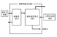
고농도유기물 처리를 위한 고효율 열분해반응조가 구비된 순환과 혼합교차교반운전 혐기소화시스템에 있어서, 고농도 가축분뇨 원료를 유입받아 가열시켜 세포막과 단백질효소의 고분자고리를 끊어 저분자로 전환시키는 열분해장치와; 상기 열분해장치에서 배출되는 혼합액을 분쇄하는 분쇄기와; 상기 분쇄기에서 분쇄된 혼합액으로부터 고액분리가 이루어지는 탈수기와; 상기 탈수기에서 분리된 액상물을 저장하여 혐기성미생물로 혐기성소화가 이루어지게 하는 혐기소화조와; 혐기소화조에서 생산된 바이오가스로 구동되어 생성된 고온스팀을 열분해장치로 공급해 열교환에 의해 혼합액이 가열되게 하는 스팀보일러와; 열분해장치에서 배출되어 분쇄기로 공급되는 혼합액과, 응축수탱크에서 스팀보일러로 공급되는 응축수를 열교환시키는 열교환기와; 각종 흐름을 제어하는 제어부;를 포함하여 구성될 수 있다.In an anaerobic digestion system for circulation and mixed cross-stir operation equipped with a high-efficiency thermal decomposition tank for processing high-concentration organic matter, the anaerobic digestion system comprising: a pyrolysis device for converting high-concentration livestock manure raw materials into low-molecular ones by breaking high molecular chains of cell membranes and protein enzymes; a pulverizer for pulverizing the mixed solution discharged from the pyrolysis device; a dehydrator for solid-liquid separation from the mixed solution pulverized by the pulverizer; an anaerobic digestion tank for storing the liquid separated in the dehydrator and performing anaerobic digestion with anaerobic microorganisms; a steam boiler that is driven by the biogas produced in the anaerobic digester and supplies the generated high-temperature steam to the pyrolysis device to heat the mixed solution by heat exchange; a heat exchanger for exchanging the mixed liquid discharged from the pyrolysis device and supplied to the grinder and the condensed water supplied from the condensate tank to the steam boiler; A control unit for controlling various flows; may be configured to include.
또한, 상기 열분해장치는, 공급받은 고농도 가축분뇨인 원료를 발전기 폐열을 이용하여 예열시키는 예열조와; 상기 예열조로부터 예열된 원료를 이송받아 고온고압에서 고분자 고리를 끊어 저분자로 변환하고, 세포막 파괴로 세포 내부수를 배출시키는 열분해가 이루어지게 하는 열분해반응조;로 이루어질 수 있다. In addition, the pyrolysis device includes: a preheating tank for preheating the supplied raw material, which is high-concentration livestock manure, using generator waste heat; It may consist of a pyrolysis reaction tank that receives the preheated raw material from the preheating tank, breaks the polymer ring at high temperature and high pressure, converts it to a low molecular weight, and pyrolyzes the cell membrane to release the water inside the cell.
또한, 상기 예열조 내부에는 나선형태로 감겨 발전기 폐열을 이송시키는 예열관이 배관되고, 상기 열분해반응조 내부에는 나선형태로 감겨 스팀보일러 스팀을 이송시키는 가열관이 배관되고, 상기 예열관과 가열관의 내측공간에는 교반기를 배치시켜 저장된 원료의 교반이 이루어질 수 있다.In addition, a preheating tube wound in a spiral shape to transfer generator waste heat is piped inside the preheating tank, and a heating tube wound in a spiral shape to transport steam boiler steam is piped in the pyrolysis reaction tank, and the preheating tube and the heating tube A stirrer may be arranged in the inner space to stir the stored raw materials.
또한, 상기 열분해반응조는 내부 반응온도를 150~155℃로 설정하여 열분해가 이루어지게 할 수 있다. In addition, the thermal decomposition reaction tank may be pyrolyzed by setting the internal reaction temperature to 150 ~ 155 ℃.
또한, 상기 혐기소화조는, 측면 하부에 펌프장치를 설치하여 저장된 액상물을 혼합하게 하되; 상기 펌프장치는, 혐기소화조와 연통되어 액상물을 인출하는 흡입관과; 상기 흡입관의 단부에 설치되어 액상물을 흡입하면서 흡입된 액상물에 포함된 고형물을 절단시키는 회전커팅날이 설치된 펌프와; 상기 펌프를 통과한 액상물을 혐기소화조로 토출시키는 토출관과; 상기 혐기소화조의 상부와 토출관의 중간지점을 연통시켜 혐기소화조 상부의 가스를 포집하여 토출관으로 공급하여 토출관으로 가스와 액상물을 함께 토출시키게 하는 가스공급관;을 포함하여 구성된다. In addition, the anaerobic digestion tank, by installing a pump device in the lower side to mix the stored liquid; The pump device includes: a suction pipe communicating with the anaerobic digestion tank to draw out the liquid; a pump installed at the end of the suction pipe and provided with a rotary cutting blade for cutting the solids contained in the sucked liquid while sucking the liquid; a discharge pipe for discharging the liquid that has passed through the pump to the anaerobic digestion tank; A gas supply pipe that connects the upper part of the anaerobic digestion tank with the middle point of the discharge pipe to collect the gas from the upper part of the anaerobic digestion tank and supply it to the discharge pipe to discharge the gas and liquid together through the discharge pipe; and is configured to include.
또한, 상기 펌프장치는 측면 하부에 2~4개를 등각으로 배치하고, 혐기소화조의 중심에서 일측으로 편향되는 방향으로 토출하여 저장된 액상물의 혼합이 이루어지게 할 수 있다. In addition, the pump device may be arranged at an angle of 2 to 4 at the lower side of the side, and discharged in a direction deflected from the center of the anaerobic digestion tank to one side to mix the stored liquid.
상기 해결수단에 의한 본 발명의 순환과 혼합교차교반운전 협기소화시스템은,The circulation and mixed cross stirring operation narrow air fire extinguishing system of the present invention by the above solution means,
내부에 나선형태의 가열관을 배관하고 그 중심공간에 교반기를 설치하여 교반되는 혼합액이 가열관의 내측과 외측을 자유롭게 왕래하면서 접촉면적을 증가시켜 열교환에 의한 신속한 가열이 가능하게 할 수 있다. A spiral heating tube is piped inside and a stirrer is installed in the central space, so that the stirred mixture moves freely inside and outside the heating tube while increasing the contact area, enabling rapid heating by heat exchange.
또한 혐기성소화조에는 커팅-그라인더펌프에 의한 교반시 가스혼합교반이 같이 수행되도록 함으로써 혼합율을 높여 혐기소화율을 높여 가연성가스인 메탄가스의 생산량을 증가시킬 수 있는 시스템의 제공이 가능하게 되었다.In addition, in the anaerobic digestion tank, gas mixing and agitation is performed together when agitating by the cutting-grinder pump, thereby increasing the mixing rate and increasing the anaerobic digestion rate to provide a system that can increase the production of methane gas, a combustible gas.
도 1은 본 발명의 바람직한 실시예에 따른 혐기소화시스템을 도시한 개략도.
도 2는 본 발명의 실시예에 따른 열분해반응조를 도시한 개략도.
도 3a와 도 3b는 본 발명에 따른 열분해반응조를 도시한 수직 및 수평 단면도.
도 4a는 본 발명에 따른 펌프장치가 설치된 혐기소화조를 도시한 수직단면도.
도 4b는 본 발명에 따른 펌프장치의 작동상태도.
도 5는 본 발명의 각 과정별로 가축분뇨 슬러지의 성장변화를 나타낸 사진.
도 6은 혐기소화조의 교반방법에 따른 메탄가스 유량을 나타낸 그래프.1 is a schematic diagram showing an anaerobic digestion system according to a preferred embodiment of the present invention.
Figure 2 is a schematic diagram showing a pyrolysis reactor according to an embodiment of the present invention.
3a and 3b are vertical and horizontal cross-sectional views showing a pyrolysis reactor according to the present invention.
Figure 4a is a vertical sectional view showing an anaerobic digestion tank installed with a pump device according to the present invention.
Figure 4b is an operating state diagram of the pump device according to the present invention.
5 is a photograph showing the growth change of livestock manure sludge for each process of the present invention.
6 is a graph showing the flow rate of methane gas according to the stirring method of the anaerobic digestion tank.
이하, 첨부한 도면을 참조하여 본 발명의 실시예에 대해 상세히 설명한다. 본 발명은 다양한 변경을 가할 수 있고 여러 가지 형태를 가질 수 있는 바, 특정 실시예들을 도면에 예시하고 본문에서 본 발명을 상세하게 설명하고자 한다. 그러나 이는 본 발명을 특정한 개시 형태에 대해 한정하려는 것이 아니며, 본 발명의 사상 및 기술 범위에 포함되는 모든 변경, 균등물 내지 대체물을 포함하는 것으로 이해되어야 한다. 각 도면을 설명하면서 유사한 참조부호를 유사한 구성요소에 대해 사용하였다. 첨부된 도면에 있어서, 구조물들의 치수는 본 발명의 명확성을 기하기 위하여 실제보다 확대 또는 축소하여 도시한 것이다.Hereinafter, embodiments of the present invention will be described in detail with reference to the accompanying drawings. Since the present invention can have various changes and can have various forms, specific embodiments are illustrated in the drawings and the present invention will be described in detail in the text. However, this is not intended to limit the present invention to the specific disclosed form, it should be understood to include all modifications, equivalents and substitutes included in the spirit and scope of the present invention. In describing each figure, like reference numerals have been used for like elements. In the accompanying drawings, the dimensions of the structures are enlarged or reduced than the actual size for clarity of the present invention.
본 출원에서 사용한 용어는 단지 특정한 실시 예를 설명하기 위해 사용된 것으로, 본 발명을 한정하려는 의도가 아니다. 단수의 표현은 문맥상 명백하게 다르게 뜻하지 않는 한, 복수의 표현을 포함한다. 본 출원에서, "포함하다", "구비하다" 또는 "가지다" 등의 용어는 명세서 상에 기재된 특징, 숫자, 단계, 동작, 구성요소 또는 이들을 조합한 것이 존재함을 지정하려는 것이지, 하나 또는 그 이상의 다른 특징들이나 숫자, 단계, 동작, 구성요소 또는 이들을 조합한 것들의 존재 또는 부가 가능성을 미리 배제하지 않는 것으로 이해되어야 한다.The terms used in the present application are only used to describe specific embodiments, and are not intended to limit the present invention. The singular expression includes the plural expression unless the context clearly dictates otherwise. In the present application, terms such as "comprise", "comprising" or "have" are intended to designate that a feature, number, step, operation, element, or combination thereof described in the specification exists, and is one or the It should be understood that the existence or addition of the above other features or numbers, steps, operations, elements or combinations thereof is not precluded in advance.
다르게 정의되지 않는 한, 기술적이거나 과학적인 용어를 포함해서 여기서 사용되는 모든 용어들은 본 발명이 속하는 기술 분야에서 통상의 지식을 가진 자에 의해 일반적으로 이해되는 것과 동일한 의미를 가지고 있다. 일반적으로 사용되고 사전에 정의되어 있는 것과 같은 용어들은 관련 기술의 문맥상 가지는 의미와 일치하는 의미를 가지는 것으로 해석되어야 하며, 본 출원에서 명백하게 정의하지 않는 한, 이상적이거나 과도하게 형식적인 의미로 해석되지 않는다.Unless defined otherwise, all terms used herein, including technical and scientific terms, have the same meaning as commonly understood by one of ordinary skill in the art to which this invention belongs. Terms such as those generally used and defined in the dictionary should be interpreted as having a meaning consistent with the meaning in the context of the related art, and are not to be interpreted in an ideal or excessively formal meaning unless explicitly defined in the present application. .
도 1은 본 발명의 바람직한 실시예에 따른 혐기소화시스템을 도시한 개략도이다.1 is a schematic diagram showing an anaerobic digestion system according to a preferred embodiment of the present invention.
참조한 바와같이 본 발명에 따른 고농도유기물 처리를 위한 고효율 열분해반응조가 구비된 순환과 혼합교차교반운전 혐기소화시스템(10)은, 고농도 가축분뇨를 원료로서 공급받아 예열시키는 열분해장치(20)를 구비한다. As referenced, the anaerobic digestion system 10 for circulation and mixing cross-stirring operation equipped with a high-efficiency pyrolysis reaction tank for processing high-concentration organic matter according to the present invention includes a pyrolysis device 20 for receiving high-concentration livestock manure as a raw material and preheating it. .
상기 열분해장치(20)는 공급받은 원료에 열을 가하여 세포막과 단백질효소의 고분자고리를 끊어 저분자로 전환시킨다. 즉, 원료를 가열시켜 고온(150℃)ㅇ고압(15kg/㎠)의 환경을 조성함으로써 물의 수소이온과 수산이온과 반응하여 고분자 고리를 끊어 저분자의 수용성 아미노산으로 성상을 변화시켜 혐기성 미생물이 난분해성 섬유질 셀룰로오스 등에 대한 소화율을 높일 수 있게 한 것이다. The thermal decomposition device 20 applies heat to the supplied raw material to break the high molecular chain of the cell membrane and the protein enzyme and convert it to a low molecular weight. In other words, by heating the raw material to create an environment of high temperature (150℃) and high pressure (15kg/cm2), it reacts with hydrogen ions and hydroxide ions of water to break the polymer ring and change the properties to low-molecular water-soluble amino acids, making the anaerobic microorganisms difficult to decompose. It is made possible to increase the digestibility of fibrous cellulose.
또한 이 과정에서 세포막이 파괴되어 내부수를 배출시킬 수 있으므로 탈수성이 향상되어 감량화가 가능해지고 고체생성물의 발열량을 높일 수 있어 고형연료로서 사용이 가능하게 할 수 있다. 또한 고온처리에 의해 슬러지내 병원균이 제거됨으로 열분해된 고형물은 퇴비로도 사용이 가능함으로 사용처를 확대시킬 수 있다. In addition, since the cell membrane is destroyed in this process and internal water can be discharged, the dehydration property is improved to reduce the weight, and the calorific value of the solid product can be increased, so that it can be used as a solid fuel. In addition, since pathogens in the sludge are removed by high-temperature treatment, the pyrolyzed solid can be used as compost, so the use can be expanded.
상기 열분해장치(20)에서 열분된 혼합액은 분쇄기(30)로 공급되고, 3500~4500rpm으로 작동하는 분쇄기에서 잔류하는 고형물을 분쇄하여 고형물크기를 작게 한다. The mixed solution pyrolyzed in the pyrolysis device 20 is supplied to the pulverizer 30, and the remaining solids are pulverized in the pulverizer operating at 3500 to 4500 rpm to reduce the size of the solids.
분쇄기를 통과한 혼합액은 탈수기(40)로 공급되어 고액분리가 이루어진다. 상기 분리된 고형물은 건조를 통해서 고형비료 또는 고형연료로서 사용되도록 하고, 액상물은 혐기소화조(50)로 공급된다.The mixed solution passing through the grinder is supplied to the dehydrator 40 to separate solid-liquid. The separated solid is dried to be used as a solid fertilizer or solid fuel, and the liquid is supplied to the
상기 혐기소화조(50)에서는 공급된 액상물을 저정하고 혐기성미생물에 의해 혐기성소화가 이루어지도록 하여 다량의 바이오가스를 생성하여 잔류물은 액상비료로 사용되도록 한다.In the
혐기소화조(50)에서 생성된 바이오가스는 스팀보일러(60)로 공급되어 연료로 사용되게 한다. 상기 스팀보일러(60)는 외부로부터 직접 급수가 이루어지게 하거나 응축수탱크(70)를 통해 수분공급이 이루어지게 할 수 있다. The biogas generated in the
스팀보일러(60)에서 생성된 스팀은 열분해장치(20)로 공급되어 원료와 열교환이 이루어지도록 하고, 열교환이 완료된 스팀은 응축수로 성상이 변화되어 응축수탱크(70)로 포집되고, 다시 스팀보일러를 통해 열분해장치로 공급되는 순환작용이 이루어진다. The steam generated in the
상기 응축수탱크(70) 전후에는 과잉응축수를 배출시키기 위한 배출밸브가 형성될 수 있고, 부족한 수분을 공급하는 급수라인이 연결될 수 있다. 열분해장치와 응축수탱크 사이에는 U트랩 등 다양한 트랩(71)이 설치되어 응축수가 역류하는 것을 방지할 수 있다. A discharge valve for discharging excess condensate may be formed before and after the condensate tank 70, and a water supply line for supplying insufficient moisture may be connected. Various traps 71 such as U traps are installed between the pyrolysis device and the condensate tank to prevent the condensate from flowing backward.
또한, 상기 열분해장치(20)에서 배출되어 분쇄기(30)로 공급되는 혼합액은 열교환기(80)를 통해서 응축수탱크(70)에서 스팀보일러(60)로 공급되는 응축수와 열교환이 이루어지게 하여 스팀보일러(60)로 공급되는 응축수의 온도를 높여 스팀생성에 소모되는 에너지소모량을 감소시킬 수 있다.In addition, the mixed solution discharged from the pyrolysis device 20 and supplied to the grinder 30 exchanges heat with the condensed water supplied from the condensate tank 70 to the
또한 상기 혐기소화시스템(10)에는 제어부(90)를 설치하여 각종 라인의 밸브를 단속하여 흐름을 제어하거나 온도나 압력 등을 제어하게 할 수 있다. In addition, a control unit 90 may be installed in the anaerobic digestion system 10 to control the flow by intermittent valves of various lines, or to control temperature or pressure.
도 2와 도 3a 및 도 3b를 참조하여 본 발명의 열분해장치를 설명하면, 본 발명의 열분해장치(20)는 예열조(21)와, 열분해반응조(22)로 분리구성된다. When the pyrolysis apparatus of the present invention is described with reference to FIGS. 2 and 3A and 3B , the pyrolysis apparatus 20 of the present invention is configured to be separated into a preheating
상기 예열조(21)는 공급받은 원료를 저장하여 예열시킨 다음 열분해반응조(22)로 이송시키는 것으로, 예열시키는 열원으로서 화력발전소나 간이 발전소 등의 발전기 폐열을 이용하여 예열이 이루어지도록 한다. The preheating
또한 상기 열분해반응조(22)는 상술한 바와같이 스팀보일러(60)에서 생성된 스팀을 제공받아 예열된 원료를 가열시켜 열분해가 이루어지도록 한다. 즉 공급받은 예열된 원료는 고온고압하에서 세포막과 단백질효소 등의 고분자고리를 끊어지게 하여 저분자로 변환시키고, 세포막을 파괴하여 세포 내부수를 배출시키는 열분해가 이루어지게 한다. In addition, the thermal
상기 예열조(21)와 열분해반응조(22)는 내부에는 내벽에 근접하여 나선형태로 감긴 예열관(211) 및 가열관(221)을 설치하여 발전기 폐열 및 스팀보일러의 스팀을 이송하게 한다. 즉, 예열조(21)의 내부에 나선 배관된 예열관(211)은 발전기 폐열을 공급받아 내부를 이동하도록 하고, 이동하는 과정에서 예열조(21)에 저장된 원료와의 열교환이 이루어져 원료를 예열시킨다. 이때 상기 원료와 예열관(211)으로 이송되는 폐열의 열교환을 촉진시키기 위해 상기 배관된 예열관(211)의 내측공간에는 교반기(212)를 배치하여 원료를 교반시키게 할 수 있다. 상기 예열조(21)는 발전기 폐열을 활용하는 것으로 기재하였으나 이에 한정하지 않고 스팀보일러에서 스팀을 공급받거나, 열분해반응조에서 배출되는 스팀을 공급받아 예열관을 통과시킨 다음 응축수로 이동되게 하는 방식으로 배관이 이루어지게 할 수 있다. The preheating
이와 마찬가지로 열분해반응조(22)에도 내벽에 근접하여 가열관(221)이 나선배관되고, 가열관의 중심공간에 교반기(222)를 설치하여 교반이 이루어지게 함으로써 저장된 원료 또는 혼합액과 가열관의 열교환량을 증가시켜 신속한 열교환이 가능하게 할 수 있다. Similarly, the
상기 예열관(211)과 가열관(221)은 예열조(21)와 열분해반응조(22) 내벽에 별도의 고정수단을 통해 내벽으로부터 일정거리 이격배치되게 함으로써 예열관 및 가열관 전체면적을 통한 열교환이 이루어지게 할 수 있다. The preheating
상기 열분해반응조(22)의 내부 반응온도는 150~155℃로 설정하여 열분해가 이루어지게 한다. 원료인 가축분노슬러지 및 고농도 가축분뇨는 150℃부터 슬러지의 플록과 세포벽 파괴에 의한 아미노산, 단백질, 핵산 등으로 구성된 EPS(Extracellular Polymeric Substances, 과세포질중합물질)의 배출에 의한 점성 증가로 탈수성능이 저하됨으로 탈수에 적합한 온도로는 150℃ 정도이다. 또한 상기 열분해반응조 내부의 반응온도는 승온시간과 감온시간을 부여하되 설정온도에서 30분 내외 예컨대 25~40분동안 반응시간을 유지하여 공급에너지 대비 효율성을 증가시키게 할 수 있다. The internal reaction temperature of the thermal
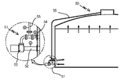
도 4a를 참조한 바와같이 상기 혐기소화조(50)에는 저장된 액상물을 혼합하기 위해 펌프장치(51)가 설치된다. As shown in Fig. 4a, a
상기 펌프장치(51)는 다양한 펌프를 사용하여 액상물의 혼합이 이루어지게 할 수 있으며, 대표적으로는 내부에 회전커팅날에 의해 흡입력을 제공하는 커팅-그라인더 펌프를 사용하여 액상물을 흡입 및 토출하는 과정에서 액상물에 잔류하는 유기물 덩어리를 작게 분쇄하여 혐기성미생물과의 접촉을 증가시켜 가스생산효율을 증대시키게 할 수 있다.The
상기 펌프장치(51)는, 혐기소화조 하부측에 연통설치하여 혐기소화조 내의 액상물을 인출하여 혐기소화조 외부로 이송시키는 흡입관(52)을 구비한다. 상기 흡입관에는 단속밸브를 설치하여 내부유로의 개폐가 이루어지게 할 수 있다. The
또한 혐기소화조 외부에 위치하는 흡입관 단부에는 펌프(53)가 설치된다. 상기 펌프는 모터구동에 의해 회전하여 흡입력을 발생시키는 부분이며 본 발명에서는 회전커팅날에 의해 흡입력을 발생시키는 커팅-그라인더 펌프를 사용한다.In addition, a
상기 펌프의 배출방향에는 토출관(54)의 일단이 연통된다. 상기 토출관은 혐기소화조로 나머지 단부가 연통되도록 설치되어 펌프에서 배출된 액상물을 혐기소화조 내부로 토출시켜 액상물의 혼합과 순환이 발생되게 할 수 있다. 상기 토출관에도 단속밸브를 설치하여 내부 유로를 단속할 수 있다.One end of the
또한 본 발명은 혐기소화조(50) 상부에 포집된 가스를 토출관(54)으로 공급하여 이송되는 액상물과 혼합하여 토출되도록 하는 가스공급관(55)이 더 설치된다. 상기 가스공급관(55)은 일단이 혐기소화조 상부와 연통되어 가스가 유입되도록하고, 다른 단부는 토출관(54)의 중간지점에 연통되어 혐기소화조 상부의 가스를 토출관으로 공급되게 한다. In the present invention, a
여기서 토출관(54)은 직선으로 배관되어 액상물이 고압으로 직진하여 토출이 이루어지며, 상기 가스공급관(55)은 토출관에 수직으로 배관되어 토출관의 토출압력에 의해 가스가 토출관으로 흡입되어 같이 토출이 이루어진다. 이때 토출관(54)으로부터 가스공급관으로의 액상물 역류를 방지하기 위해 가스공급관(55)에는 체크밸브를 장착하거나, 가스공급관과 토출관의 유입부분 사이의 각도를 예각으로 형성할 수 있다. Here, the
이외에 상기 가스공급관에 펌프를 추가로 장착하여 가스를 고압으로 토출관에 공급하여 가스혼합량을 증가시킬 수 있다. In addition, a pump may be additionally mounted on the gas supply pipe to supply gas to the discharge pipe at high pressure to increase the gas mixture amount.
상기 혐기소화조(50)에 설치되는 펌프장치(51)는, 2~4개를 등각으로 배치할 수 있다.Two to four
도 4b는 3개의 펌프장치(51)를 등각으로 설치하여 혐기소화조(50) 내부 교반이 이루어지게 한 것이다. 상기 각 펌프장치의 토출방향은 혐기소화조의 중심에서 일측으로 편향시켜 혐기소화조 내의 액상물이 일측방향으로 회전하면서 교반이 이루어지게 할 수 있다. Figure 4b shows that three
1. 열분해장치의 열분해반응기의 최적 운전온도 산정1. Estimation of optimum operating temperature of pyrolysis reactor of pyrolysis device
1-1) 실험조건1-1) Experimental conditions
실험장치로는 본 발명의 도 1와 도 2가 적용된 혐기소화시스템을 적용하였다. 예컨대 예열조와 열분해반응조를 구비한 열분해장치를 구비하고, 예열조는 발전기의 폐열을 공급받아 예열되도록 하고, 열분해반응조는 스팀보일러에 의해 스팀을 공급하여 가열하였다. 스팀보일러로 공급되는 수분은 응축수탱크로부터 제공되되 공급이전에 열교환기를 통해서 열분해반응조에서 배출되는 혼합액과 열교환이 이루어지게 하였다. 혼합액은 분쇄기를 통과하여 탈수기로 공급되어 고액분리가 이루어지고, 분리된 액상물은 혐기소화조로 공급하여 혐기소화가 이루어지도록 구성하였다. As an experimental device, the anaerobic digestion system to which FIGS. 1 and 2 of the present invention was applied was applied. For example, a pyrolysis device having a preheating tank and a pyrolysis tank is provided, the preheating tank is supplied with waste heat of a generator to be preheated, and the pyrolysis tank is heated by supplying steam by a steam boiler. Moisture supplied to the steam boiler is provided from the condensate tank, and heat exchange is made with the mixed solution discharged from the pyrolysis reactor through a heat exchanger before supply. The mixed solution was passed through a grinder and supplied to a dehydrator to perform solid-liquid separation, and the separated liquid was supplied to an anaerobic digestion tank to achieve anaerobic digestion.
가축분노 슬러지 혼합액의 TS는 22%, 함수율은 78%였으며, 고농도 가축분뇨의 TS는 8%, 함수율은 92%였으며 40kg씩 채취하여 장치에 투입하였다.The TS of the livestock dung sludge mixture was 22% and the moisture content was 78%, and the TS of the high-concentration livestock manure was 8% and the moisture content was 92%.
실험후 발생된 액상생성물 및 탈리액의 특성을 분석하기 위하여 수질오염공정시험기준에 따라 수질분석을 실시하였다. In order to analyze the characteristics of the liquid product and desorbent generated after the experiment, water quality analysis was performed according to the water pollution process test standards.
또한, 탈수과정 후 생성된 고체생성물의 화학적 조성을 분석하기 위해 Elemental Analyzer(Flash EA 1112 series)를 이용하여 원소분석을 진행하였다. In addition, elemental analysis was performed using an Elemental Analyzer (Flash EA 1112 series) to analyze the chemical composition of the solid product produced after the dehydration process.
또한, 연료로서의 가치를 평가하기 위해 KS E3709 규정에 근거하여 공업분석과 발열량을 측정하였다. In addition, in order to evaluate the value as a fuel, industrial analysis and calorific value were measured based on KS E3709 regulations.
또한, 환경 중 위해성을 평가하기 위하여 수질오염공정시험기준에 따라 중금속 함량을 분석하였다. In addition, in order to evaluate the environmental risk, the content of heavy metals was analyzed according to the water pollution process test standards.
열분해반응은 가축분뇨 및 슬러지의 탈수능력을 향상시켜 수분을 제거하는 감량화 목적 외에 열분해반응 후 발생되는 고체생성물의 발열량을 측정한 결과 고형연료로 이용할 수 있는 에너지화에 효과가 있다. In addition to the purpose of reducing moisture by improving the dehydration ability of livestock manure and sludge, the thermal decomposition reaction measures the calorific value of the solid product generated after the thermal decomposition reaction and is effective in converting energy that can be used as a solid fuel.
1-2) 성분분석1-2) Component Analysis
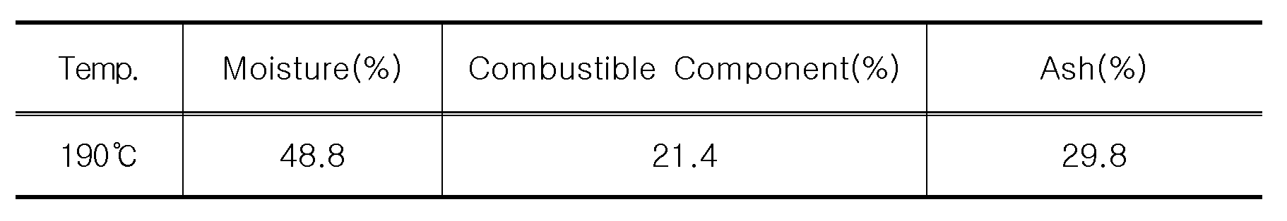
고체생성물의 특성과 연료화 가능성을 평가하기 위해 탈수가 가능한 반응온도 150℃이상의 가축분뇨 슬러지 탈수케이크를 대상으로 삼성분 분석과 원소분석, 발열량 분석을 실시하였고, 그 결과를 [표1-1]과 [표1-2]에 나타내었다. In order to evaluate the characteristics of solid products and the possibility of turning them into fuels, ternary analysis, elemental analysis, and calorific value analysis were performed on livestock manure sludge dewatered cakes with a reaction temperature of 150°C or higher for dehydration. The results are presented in [Table 1-1] and It is shown in [Table 1-2].
[표 1-1]은 가축분뇨 슬러지 탈수케이크의 분석이고, [표 1-2]는 가축분뇨 슬러지 탈수케이크의 원소분석 및 발열량 분석을 표시하였다. [Table 1-1] is the analysis of the dewatered cake of livestock manure sludge, and [Table 1-2] shows the elemental analysis and the calorific value analysis of the dehydrated cake of livestock manure sludge.
[표 1-1][Table 1-1]

[표 1-2][Table 1-2]
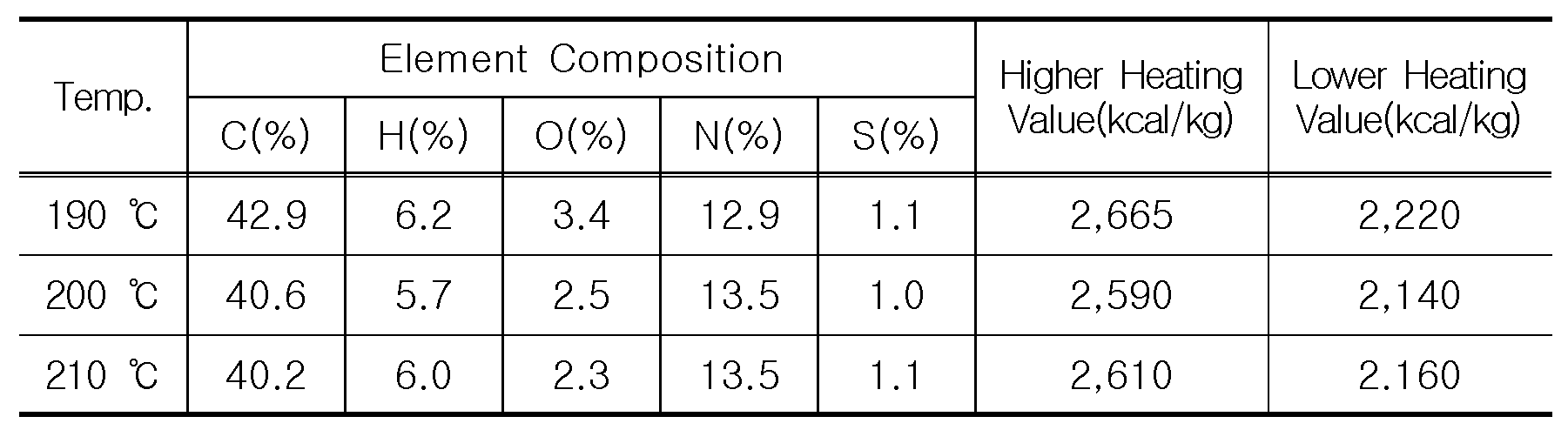
분석결과, 반응 온도별로 수분량과 회분량, 원소조성, 발열량에 큰 차이가 없었다. 수분은 47.8~49.2%로 50%이하를 나타냈으며, 가연분은 21.4~22.8%, 회분은 29.4~29.8%로 나타났다. 또한, 원소분석 결과 탄소(C)함량은 40%이상으로 다른 원소보다 높게 분석되었다. 회분함량이 비교적 높아 연료화 특성은 좋은 편은 아니지만, 반응온도 150℃일 때의 고위발열량은 2,665kcal/kg, 저위발열량은 2,220kcal/kg으로 연료로서 충분히 가치가 있는 것으로 판단된다. 따라서, 고형분은 폐열을 활용해 건조 후 열분해 설비의 자체 열원으로 사용이 가능하며, 발전설비에 공급하는 등 활용 가치를 높일 수 있다. As a result of the analysis, there was no significant difference in moisture content, ash content, elemental composition, and calorific value by reaction temperature. The moisture content was 47.8~49.2%, which was less than 50%, and the combustible content was 21.4~22.8%, and the ash content was 29.4~29.8%. In addition, as a result of elemental analysis, the carbon (C) content was analyzed to be more than 40% higher than other elements. Although the ash content is relatively high, the fuel conversion characteristics are not good, but when the reaction temperature is 150℃, the high calorific value is 2,665 kcal/kg and the low calorific value is 2,220 kcal/kg, which is judged to be sufficiently valuable as a fuel. Therefore, the solid content can be used as its own heat source for the pyrolysis facility after drying by using waste heat, and the utilization value can be increased by supplying it to the power generation facility.
상기 실험결과 반응온도 150℃가 최적 운전온도인 것으로 판단되어, 고농도 가축분뇨를 운전온도 150도로 운전하여 발생한 탈수케이크의 삼성분 분석과 원소분석, 발열량 분석을 실시하였고, 그 결과를 [표 1-3]과 [표 1-4]로 나타냈다. [Table 1-] 3] and [Table 1-4].
하기 [표 1-3]은 고농도 가축분뇨 탈수케이크의 공업분석이고, [표 1-4]는 고농도 가축분뇨 원소분석 및 발열량 분석을 표시하였다. The following [Table 1-3] is an industrial analysis of high-concentration livestock manure dehydrated cake, and [Table 1-4] shows the analysis of high-concentration livestock manure elements and calorific value.
[표 1-3][Table 1-3]
[표 1-4][Table 1-4]

참조한 바와같이 가축분뇨 슬러지 탈수케이크와 마찬가지로 함수율은 50%이하로 나타났고, 탄소함유량이 높게 나타났으며, 저위발열량이 2,160kcal/kg으로 건조 후 연료로서 활용가능성이 높은 것으로 나타났다. As mentioned, the moisture content was less than 50%, the carbon content was high, and the low calorific value was 2,160 kcal/kg, similar to the dewatered cake of livestock manure sludge.
2. 양돈분뇨 및 우분 투입에 따른 최적 운전조건 산정2. Estimation of optimal operating conditions according to pig manure and cow manure input
2-1) 실험방법2-1) Experimental method
양돈분뇨 및 우분 투입조건에 따른 최적의 열분해 반응기 온도, 압력조건, 반응시간, 운전방안 및 반응물의 온도변화에 대해 실험하였다.Experiments were conducted on the optimal pyrolysis reactor temperature, pressure conditions, reaction time, operation method, and temperature change of reactants according to pig manure and cattle manure input conditions.
가축분뇨 및 슬러지를 실험대상으로 하였으며, 가축분뇨 및 우분의 주성분은 단백질과 헤미셀룰로오스(hemicellulose)가 주성분이기 때문에 150℃이상에서 분해가 가능하고, 열분해 온도가 200℃이상일 경우에는 혐기성 소화 저해물질이 발생하여 메탄가스 발생이 저하되는 것으로 알려져 있다. 따라서 본 실험에서는 운전온도를 130℃에서 200℃까지 변화를 주면서 실행하였다.Livestock manure and sludge were tested. Since the main components of livestock manure and cow manure are protein and hemicellulose, it can be decomposed at 150℃ or higher, and when the thermal decomposition temperature is 200℃ or higher, anaerobic digestion inhibitors are generated. Therefore, it is known that the generation of methane gas is reduced. Therefore, in this experiment, the operating temperature was changed from 130°C to 200°C.
운전압력은 설정 운전온도 증가에 따라 12.72 ~ 22.20kg/cm2까지 증가되었다. 이때 반응기 내부의 압력은 슬러지의 부피증가로 인해 해당 온도의 포화수증기압보다 좀 더 높은 수증기압이 형성되게 된다. The operating pressure increased to 12.72 ~ 22.20kg/cm2 as the set operating temperature increased. At this time, the pressure inside the reactor is higher than the saturated water vapor pressure of the corresponding temperature due to the increase in the volume of the sludge.
운전에 총 소요된 시간은 승온시간 60분, 증기 투입시간 60분, 운전(반응)시간 30분, 감온ㅇ감압 시간 60분, 총 210분 실시하였다. 실험을 통해서 열분해 최적 운전시간은 30분으로 운전시간을 길게 하면 열가수분해 효율이 증가되기는 하지만, 반응 시간이 증가할수록 투입되는 에너지의 양 또한 증가되고, 30분 이상이 되면 효율 증가도 미미한 것으로 나타났다. 따라서 경제성을 고려하여 최적 운전시간인 30분간 운전을 진행하였다. The total time required for operation was 60 minutes for temperature increase, 60 minutes for steam input, 30 minutes for operation (reaction) time, 60 minutes for temperature reduction/decompression time, a total of 210 minutes. According to the experiment, the optimal operating time for pyrolysis is 30 minutes, and if the operating time is longer, the pyrohydrolysis efficiency increases, but as the reaction time increases, the amount of energy input also increases. . Therefore, in consideration of economic feasibility, the optimum operation time was operated for 30 minutes.
실험 후 발생된 액상생성물 및 탈리액의 특성을 분석하기 위하여 수질오염공정시험기준에 따라 수질분석을 실시하였다. In order to analyze the characteristics of the liquid product and desorbent generated after the experiment, water quality analysis was performed according to the water pollution process test standards.
2-2) 실험결과2-2) Experiment result
도 5는 가축분뇨 슬러지의 성상변화에 과정을 사진으로 나타내었다. 열분해과정을 통해서 다량의 수분이 분리됨을 확인할 수 있었다. 5 is a photograph showing the process of change in the properties of livestock manure sludge. It was confirmed that a large amount of moisture was separated through the pyrolysis process.
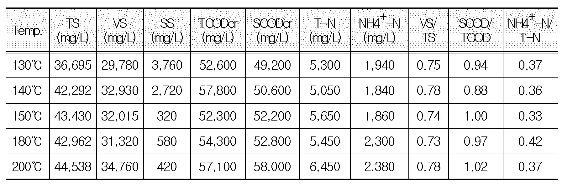
가축분뇨 슬러지의 열가수분해 반응 후 생성된 액상생성물의 수질분석 결과, 운전(반응) 온도가 올라감에 따라 가용화율이 높아지는 것을 확인 할 수 있었다. 가용화란 슬러지 내 미생물의 세포벽을 파괴하여 고상물질을 용존성 물질로 변화시키는 것으로 생분해성을 높여 혐기소화 시 바이오가스 발생률이 증가된다. 일반적으로 가용화 특성을 알아보는 대표적인 지표로서 사용되는 것이 SCODCr, NH4+-N과 SCODCr/TCODCr 비율의 증가를 들 수 있다. As a result of water quality analysis of the liquid product produced after the thermal hydrolysis reaction of livestock manure sludge, it was confirmed that the solubilization rate increased as the operating (reaction) temperature increased. Solubilization is to change the solid material into a soluble material by destroying the cell wall of microorganisms in the sludge. In general, SCOD Cr , NH4 + -N, and SCOD Cr /TCOD Cr ratio increase is used as a representative indicator to determine the solubilization characteristics.
하기 [표 2-1]은 가축분뇨 슬러지 처리 반응온도에 따른 액상생성물의 특성을 나타내었다. The following [Table 2-1] shows the characteristics of the liquid product according to the reaction temperature of the livestock manure sludge treatment.
[표 2-1][Table 2-1]

본 실험에서는 반응온도가 증가함에 따라 표 2-1과 같이 SCODCr, NH4+-N의 농도가 높아지는 것을 확인 할 수 있었으며, NH4+-N/T-N의 비율도 증가하였는데 열분해 반응이 진행되면서 유기성 질소들이 암모니아성 질소로 변환된 것으로 사료된다. In this experiment, as the reaction temperature increased, as shown in Table 2-1, it was confirmed that the concentrations of SCOD Cr , NH4 + -N increased, and the ratio of NH4 + -N/TN also increased. As the thermal decomposition reaction proceeded, organic nitrogen It is thought to have been converted to ammonia nitrogen.
또한, 반응온도가 높아짐에 따라 TS와 TCODCr은 증가하고 SS가 감소하는 것을 확인 할 수 있었는데 이는 열분해 반응을 통해 고형물의 액상화가 진행되고 용존성 물질이 증가한 것으로 판단된다. In addition, as the reaction temperature increased, it was confirmed that TS and TCOD Cr increased and SS decreased.
[표 2-2]는 고농도 가축분뇨 처리 반응온도에 따른 액상생성물 특성을 나타내었다.[Table 2-2] shows the characteristics of liquid products according to the reaction temperature of high concentration livestock manure.
[표 2-2][Table 2-2]

고농도 가축분뇨 슬러지(TS 8%)를 사용한 실험결과를 나타낸 [표 2-2]를 보면 가축분뇨 슬러지를 사용한 [표 2-1]과 비슷한 처리경향이 나타냄을 확인할 수 있었다. 즉, 운전반응온도가 올라감에 따라 가용화율이 높아지는 것을 확인할 수 있었다. Looking at [Table 2-2] showing the experimental results using high-concentration livestock manure sludge (TS 8%), it was confirmed that the treatment tendency was similar to that of [Table 2-1] using livestock manure sludge. That is, it was confirmed that the solubilization rate increased as the operating reaction temperature increased.
하기 [표 2-3]과 [표 2-4]는 가축분뇨 슬러지 및 고농도 가축분뇨 슬러지의 처리 반응온도에 따른 탈리액 특성을 나타내었다. The following [Table 2-3] and [Table 2-4] show the characteristics of the desorbent according to the treatment reaction temperature of livestock manure sludge and high-concentration livestock manure sludge.
[표 2-3][Table 2-3]
[표 2-4][Table 2-4]

상기 [표 2-3]과 [표 2-4]는 가축분뇨 슬러지 및 고농도 가축분뇨 처리 후 발생한 액상생성물을 탈수기로 탈수한 후 분리된 탈리액의 수질분석 결과이다. [Table 2-3] and [Table 2-4] are the results of water quality analysis of the desorbed liquid separated after dehydrating the liquid product generated after treatment of livestock manure sludge and high-concentration livestock manure with a dehydrator.
반응온도가 170 ℃, 180 ℃인 탈리액의 SS가 다른 온도보다 높은데, 이는 탈수가 원활하게 되지 않았기 때문이다. 열가수분해 반응은 슬러지의 플록과 세포벽을 파괴하여 탈수성을 높이는 방법이지만, 반응온도 190℃미만에서는 슬러지의 플록과 세포벽 파괴에 의한 아미노산, 단백질, 핵산 등으로 구성된 EPS(Extracellular Polymeric Substances, 과세포질중합물질)의 배출에 의한 점성 증가로 탈수성능을 저하하는 것으로 보인다. 150 ℃부터 EPS 물질이 파괴되기 시작하여 180 ℃부터는 EPS 물질이 대부분 파괴된 것으로 판단된다. The SS of the desorbent having reaction temperatures of 170 °C and 180 °C is higher than other temperatures, because dehydration was not smooth. Thermal hydrolysis reaction is a method to increase dehydration by destroying flocs and cell walls of sludge, but at a reaction temperature of less than 190℃, EPS (Extracellular Polymeric Substances, supercytoplasmic) composed of amino acids, proteins, nucleic acids, etc. It seems that the dehydration performance is lowered due to the increase in viscosity due to the discharge of polymeric substances). The EPS material starts to be destroyed at 150 °C, and it is judged that most of the EPS material is destroyed from 180 °C.
상기 결과를 종합하여 판단하면, 150 ℃가 탈수에 필요한 최소온도인 것으로 사료되며, 가용화율을 나타내는 지표인 SCODCr/TCODCr 비율 또한 150℃부터 1에 수렴하는 것을 봤을 때 경제성까지 고려한 열가수분해 반응 최적온도는 150 ℃인 것으로 판단된다. Judging from the above results, it is considered that 150 ° C is the minimum temperature required for dehydration, and when the SCOD Cr / TCOD Cr ratio, which is an index indicating the solubilization rate, also converges to 1 from 150 ° C., thermal hydrolysis considering economic feasibility. The optimum reaction temperature is determined to be 150 °C.
또한 탈수 후 고형물(TS) 제거율은 가축분뇨 슬러지의 경우 평균 81%의 제거율을 나타냈으며, 고농도 가축분뇨의 경우 평균 82%의 제거율로 높게 나타남을 알 수 있었다. In addition, the removal rate of solids (TS) after dehydration showed an average removal rate of 81% for livestock manure sludge, and it was found that the removal rate for high-concentration livestock manure was high with an average removal rate of 82%.
3. 커팅-그라인더 펌프 순환 및 가스혼합 교반을 교차운전하는 방법을 이용한 최적의 혐기소화 선정3. Selection of optimal anaerobic digestion using the method of cross-operation of cutting-grind pump circulation and gas mixing and agitation
소화조에 열가수분해 반응을 마친 원료를 투입하여 혐기소화 시 발생되는 메탄가스 유량 데이터를 수집하고 교반방법별 메탄가스 발생량을 측정하여 최적의 교반방법을 검토하였다.The optimal stirring method was reviewed by inputting the raw material after the thermal hydrolysis reaction into the digester, collecting methane gas flow data generated during anaerobic digestion, and measuring the amount of methane gas generated by each stirring method.
1) 측정방법1) Measurement method
메탄가스 발생 유량에 대한 데이터는 [표 3]과 같이 각각의 교반방법과 측정기간에 따라 측정하였다. The data on the flow rate of methane gas was measured according to each stirring method and measurement period as shown in [Table 3].
[표 3][Table 3]

상기 외부펌프 순환식 교반은 소화조의 외부에 펌프를 설치하여 소화조 내, 저부의 액상물질을 인출하여 다시 상부로 토출하는 방식이다.The external pump circulation type agitation is a method in which a pump is installed on the outside of the digester to withdraw the liquid material from the inside and the bottom of the digester and discharge it back to the upper part.
또한 커팅 그라인더 펌프 교반은 슬러지 부유물질을 절단, 교반하는 방법이다.Also, cutting grinder pump agitation is a method of cutting and stirring suspended sludge.
또한, 가스혼합은 벤츄리 원리로 가스와 슬러지를 혼합하여 노즐을 통해 토출하는 방법이다.In addition, gas mixing is a method of mixing gas and sludge according to the venturi principle and discharging it through a nozzle.
또한, 커팅 그라인더 펌프펌프 교반+가스혼합 교반은 커팅 그라인더 펌프 교반과 가스혼합 교반을 교차 운전하는 방법이다.In addition, the cutting grinder pump pump stirring + gas mixing stirring is a method of cross-operating the cutting grinder pump stirring and gas mixing stirring.
상기 교반측정은 2개의 혐기소화조(R1,R2)를 이용하여 각각 측정하였다. The stirring was measured using two anaerobic digestion tanks (R1, R2), respectively.
2) 측정결과2) Measurement result
각 방법마다 데이터 수집기간이 상이하여 메탄가스 발생량에 대한 평균유량으로 검토하였다.Since the data collection period is different for each method, the average flow rate for methane gas generation was reviewed.
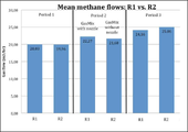
혐기소화 후 생성되는 메탄가스 평균 유량을 측정한 결과 그래프를 도 6에 나타내었다. The result of measuring the average flow rate of methane gas produced after anaerobic digestion is shown in FIG. 6 .
참조한 바와같이 1-R1 : 20.03㎥/hr, 1-R2 : 19.96㎥/hr, 2-R1 : 22.27㎥/hr, 2-R2 : 21.68㎥/hr, 3-R1 : 24.16㎥/hr, 3-R2 : 25.06㎥/hr로 나타났다.As referenced, 1-R1: 20.03㎥/hr, 1-R2: 19.96㎥/hr, 2-R1: 22.27㎥/hr, 2-R2: 21.68㎥/hr, 3-R1: 24.16㎥/hr, 3- R2: It was found to be 25.06 m3/hr.
외부펌프 순환식 교반의 메탄발생량 대비 커팅 그라인더 펌프 순환식 교반의 메탄발생량은 8%이상 증가한 것으로 나타났으며, 커팅 그라인더 펌프 순환식 교반의 메탄발생량 대비 커팅 그라인더 펌프 순환식+가스혼합 교반의 메탄발생량은 2%이상 증가한 것으로 나타났다. 또한 외부펌프 순환식 교반의 메탄발생량 대비 커팅 그라인더 펌프 순환식+가스혼합 교반의 메탄발생량은 23%이상 증가한 것으로 나타났다. It was found that the methane generation of the circulating agitation of the cutting grinder pump increased by more than 8% compared to the methane generation of the external pump circulation type agitation, and the methane generation amount of the cutting grinder pump circulation type + gas mixture stirring compared to the methane generation amount of the cutting grinder pump circulation type stirring showed an increase of more than 2%. In addition, compared to the amount of methane generated by external pump circulation type agitation, it was found that the methane generation amount of the cutting grinder pump circulation type + gas mixture stirring increased by more than 23%.
상기 결과를 종합적으로 판단하면, 커팅 그라인더 펌프 순환식+가스혼합 교반방법이 가장 효과적인 것으로 나타났다. Comprehensively judging the above results, the cutting grinder pump circulation type + gas mixture stirring method was found to be the most effective.
3) 커팅 그라인더 펌프 및 가스 혼합 교반 효과3) Cutting grinder pump and gas mixing stirring effect
커팅 그라인더 펌프 및 가스 혼합교반은, 유기물덩어리를 잘게 게 분쇄하여 혐기 미생물 접촉 증가로 발생가스를 증가시켜 가스효율을 증대시킬 수 있다. The cutting grinder pump and gas mixing and agitation can increase gas efficiency by finely pulverizing the organic mass and increasing the generated gas by increasing contact with anaerobic microorganisms.
또한 상부 메탄가스를 통해서 연속적으로 혼합공급함으로 스컴층을 제거할 수 있다. In addition, the scum layer can be removed by continuously mixing and supplying through the upper methane gas.
또한, 펌프가 외부에 설치되기 때문에 유지보수 및 관리운영 용이하고, 타 교반기보다 내구성이 높아 사용시간을 증가시킬 수 있다. In addition, since the pump is installed outside, maintenance and management are easy, and the use time can be increased because of its higher durability than other agitators.
또한, TS 10% 이상의 조건에서도 교반이 가능하고 스컴이나 침전이 생기지 않거나 최소화 할 수 있는 장점이 있다. In addition, stirring is possible even under conditions of 10% or more of TS, and there is an advantage that scum or precipitation does not occur or can be minimized.
10 : 혐기소화시스템
20 : 열분해장치
21 : 예열조
22 : 열분해반응조
211 : 예열관
212,222 : 교반기
221 : 가열관
30 : 분쇄기
40 : 탈수기
50 : 혐기소화조
51 : 펌프장치
52 : 흡입관
53 : 펌프
54 : 토출관
55 : 가스공급관
60 : 스팀보일러
70 : 응축수탱크
71 : 트랩
80 : 열교환기
90 : 제어부10: anaerobic digestion system
20: pyrolysis device
21: preheating tank 22: pyrolysis reaction tank
211: preheating tube 212,222: agitator
221: heating tube
30: grinder
40: dehydrator
50: anaerobic digestion tank
51: pump device 52: suction pipe
53: pump 54: discharge pipe
55: gas supply pipe
60: steam boiler
70: condensate tank
71 : trap
80: heat exchanger
90: control unit
Claims (6)
고농도 가축분뇨 원료를 유입받아 예열시켜 세포막과 단백질효소의 고분자고리를 끊어 저분자로 전환시키는 열분해장치(20)와;
상기 열분해장치에서 배출되는 혼합액을 분쇄하는 분쇄기(30)와;
상기 분쇄기에서 분쇄된 혼합액으로부터 고액분리가 이루어지는 탈수기(40)와;
상기 탈수기에서 분리된 액상물을 저장하여 혐기성미생물로 혐기성소화가 이루어지게 하는 혐기소화조(50)와;
혐기소화조에서 생산된 바이오가스로 구동되어 생성된 고온스팀을 열분해장치로 공급해 열교환에 의해 혼합액이 가열되게 하는 스팀보일러(60)와;
열분해장치(20)에서 배출되어 분쇄기(30)로 공급되는 혼합액과, 응축수탱크(70)에서 스팀보일러(60)로 공급되는 응축수를 열교환시키는 열교환기(80)와;
각종 흐름을 제어하는 제어부(90);를 포함하여 구성되는 것을 특징으로 하는 순환과 혼합교차교반운전 혐기소화시스템.In the anaerobic digestion system for circulation and mixed cross-stirring operation equipped with a high-efficiency pyrolysis tank for high-concentration organic matter treatment,
a thermal decomposition device 20 for receiving high-concentration livestock manure raw material and preheating it to break the high molecular chain between the cell membrane and the protein enzyme and convert it to a low molecular weight;
a pulverizer 30 for pulverizing the mixed solution discharged from the pyrolysis device;
a dehydrator 40 for solid-liquid separation from the mixed solution pulverized in the pulverizer;
an anaerobic digestion tank 50 for storing the liquid separated in the dehydrator and performing anaerobic digestion with anaerobic microorganisms;
a steam boiler 60 that is driven by biogas produced in the anaerobic digester and supplies the generated high-temperature steam to the pyrolysis device to heat the mixed solution by heat exchange;
a heat exchanger 80 for exchanging heat between the mixed liquid discharged from the pyrolysis device 20 and supplied to the grinder 30 and the condensed water supplied from the condensed water tank 70 to the steam boiler 60;
Anaerobic digestion system for circulation and mixed cross-stirring operation, characterized in that it includes; a control unit 90 for controlling various flows.
상기 열분해장치(20)는,
공급받은 고농도 가축분뇨인 원료를 발전기 폐열을 이용하여 예열시키는 예열조(21)와;
상기 예열조로부터 예열된 원료를 이송받아 고온고압에서 고분자 고리를 끊어 저분자로 변환하고, 세포막 파괴로 세포 내부수를 배출시키는 열분해가 이루어지게 하는 열분해반응조(22);로 이루어지는 것을 특징으로 하는 순환과 혼합교차교반운전 혐기소화시스템.According to claim 1,
The pyrolysis device 20,
a preheating tank 21 for preheating the supplied raw material, which is high-concentration livestock manure, using generator waste heat;
A pyrolysis reactor 22 that receives the preheated raw material from the preheating tank, breaks the polymer ring at high temperature and high pressure, converts it to a low molecular weight, and discharges the water inside the cell by breaking the cell membrane. Mixed cross agitation operation anaerobic digestion system.
상기 예열조(21) 내부에는 나선형태로 감겨 발전기 폐열을 이송시키는 예열관(211)이 배관되고,
상기 열분해반응조(22) 내부에는 나선형태로 감겨 스팀보일러 스팀을 이송시키는 가열관(221)이 배관되고,
상기 예열관(211)과 가열관(221)의 내측공간에는 교반기(212,222)를 배치시켜 저장된 원료의 교반이 이루어지도록 하는 것을 특징으로 하는 순환과 혼합교차교반운전 혐기소화시스템.3. The method of claim 2,
A preheating tube 211 is piped inside the preheating tank 21 to transfer waste heat from the generator wound in a spiral shape,
A heating tube 221 is piped inside the pyrolysis reaction tank 22, which is wound in a spiral shape to transport steam boiler steam,
Anaerobic digestion system for circulation and mixing cross-stirring operation, characterized in that by disposing agitators (212,222) in the inner space of the preheating tube (211) and the heating tube (221), the stored raw material is stirred.
상기 열분해반응조(22)는 내부 반응온도를 150~155℃로 설정하여 열분해가 이루어지게 한 것을 특징으로 하는 순환과 혼합교차교반운전 혐기소화시스템.3. The method of claim 2,
The pyrolysis reaction tank 22 is an anaerobic digestion system with circulation and mixed cross-stirring operation, characterized in that the internal reaction temperature is set to 150 ~ 155 ℃ so that the thermal decomposition is made.
상기 혐기소화조(50)는, 측면 하부에 펌프장치(51)를 설치하여 저장된 액상물을 혼합하게 하되;
상기 펌프장치(51)는,
혐기소화조와 연통되어 액상물을 인출하는 흡입관(52)과;
상기 흡입관의 단부에 설치되어 액상물을 흡입하면서 흡입된 액상물에 포함된 고형물을 절단시키는 회전커팅날이 설치된 펌프(53)와;
상기 펌프를 통과한 액상물을 혐기소화조로 토출시키는 토출관(54)과;
상기 혐기소화조의 상부와 토출관의 중간지점을 연통시켜 혐기소화조 상부의 가스를 포집하여 토출관으로 공급하여 토출관으로 가스와 액상물을 함께 토출시키게 하는 가스공급관(55);을 포함하여 구성되는 것을 특징으로 하는 순환과 혼합교차교반운전 혐기소화시스템.According to claim 1,
The anaerobic digestion tank 50, a pump device 51 is installed in the lower side to mix the stored liquid;
The pump device 51,
a suction pipe 52 communicating with the anaerobic digestion tank and withdrawing the liquid;
a pump 53 installed at the end of the suction pipe and provided with a rotary cutting blade for cutting the solids contained in the sucked liquid while sucking the liquid;
a discharge pipe 54 for discharging the liquid that has passed through the pump to the anaerobic digestion tank;
A gas supply pipe (55) that connects the upper part of the anaerobic digestion tank and the middle point of the discharge pipe to collect the gas at the upper part of the anaerobic digestion tank and supply it to the discharge pipe to discharge the gas and the liquid together through the discharge pipe; Anaerobic digestion system, characterized in that the circulation and mixed cross agitation operation.
상기 펌프장치(51)는 측면 하부에 2~4개를 등각으로 배치하고, 혐기소화조(50)의 중심에서 일측으로 편향되는 방향으로 토출하여 저장된 액상물의 혼합이 이루어지게 한 것을 특징으로 하는 순환과 혼합교차교반운전 혐기소화시스템.
6. The method of claim 5,
The pump device 51 is arranged at an angle of 2 to 4 in the lower side of the side, and discharged in a direction deflected from the center of the anaerobic digestion tank 50 to one side to mix the stored liquid. Circulation and Mixed cross agitation operation anaerobic digestion system.
Priority Applications (1)
| Application Number | Priority Date | Filing Date | Title |
|---|---|---|---|
| KR1020200169684A KR102422954B1 (en) | 2020-12-07 | 2020-12-07 | Anaerobic Digestion System for Circulation and Mixed Crossing Operation with High-Efficiency Pyrolysis Reactor for Treating High-Concentration Organic |
Applications Claiming Priority (1)
| Application Number | Priority Date | Filing Date | Title |
|---|---|---|---|
| KR1020200169684A KR102422954B1 (en) | 2020-12-07 | 2020-12-07 | Anaerobic Digestion System for Circulation and Mixed Crossing Operation with High-Efficiency Pyrolysis Reactor for Treating High-Concentration Organic |
Publications (2)
| Publication Number | Publication Date |
|---|---|
| KR20220080504A true KR20220080504A (en) | 2022-06-14 |
| KR102422954B1 KR102422954B1 (en) | 2022-07-20 |
Family
ID=81980231
Family Applications (1)
| Application Number | Title | Priority Date | Filing Date |
|---|---|---|---|
| KR1020200169684A KR102422954B1 (en) | 2020-12-07 | 2020-12-07 | Anaerobic Digestion System for Circulation and Mixed Crossing Operation with High-Efficiency Pyrolysis Reactor for Treating High-Concentration Organic |
Country Status (1)
| Country | Link |
|---|---|
| KR (1) | KR102422954B1 (en) |
Families Citing this family (2)
| Publication number | Priority date | Publication date | Assignee | Title |
|---|---|---|---|---|
| KR102542771B1 (en) * | 2022-10-11 | 2023-06-14 | 한국수자원공사 | Two Stage Hybrid Anaerobic Digestion System and Operating Method of the same |
| KR102542778B1 (en) * | 2022-10-12 | 2023-06-15 | 한국수자원공사 | Semi Dry Anaerobic Digestion System for non Discharge Water and Operating Method of the same |
Citations (6)
| Publication number | Priority date | Publication date | Assignee | Title |
|---|---|---|---|---|
| KR100943315B1 (en) * | 2009-06-09 | 2010-02-19 | (주)정봉 | Apparatus and method for treating organic sludge using thermal hydrolysis and high-temperature anaerobic digestion |
| KR20100043706A (en) * | 2008-10-21 | 2010-04-29 | 주성호 | The gas manufacture system which uses the organic waste |
| KR20140018770A (en) * | 2012-08-03 | 2014-02-13 | 주식회사 에코비젼 | Energy-saving sewage sludge solubilization device and method |
| KR20160006549A (en) * | 2014-07-09 | 2016-01-19 | 디에이치엠(주) | Organic waste heating system by using waste heat of liquid manure used in the anaerobic digester in winter, and method for increasing biogas |
| KR102029117B1 (en) | 2019-01-31 | 2019-11-08 | 황연수 | Anaerobic digestion apparatus for treating organic waste using the thermal hydrolysis |
| KR20200048220A (en) | 2018-10-29 | 2020-05-08 | 주식회사 포스코건설 | Thermal hydrolysis reaction anaerobic digestion system of organic waste |
-
2020
- 2020-12-07 KR KR1020200169684A patent/KR102422954B1/en active
Patent Citations (6)
| Publication number | Priority date | Publication date | Assignee | Title |
|---|---|---|---|---|
| KR20100043706A (en) * | 2008-10-21 | 2010-04-29 | 주성호 | The gas manufacture system which uses the organic waste |
| KR100943315B1 (en) * | 2009-06-09 | 2010-02-19 | (주)정봉 | Apparatus and method for treating organic sludge using thermal hydrolysis and high-temperature anaerobic digestion |
| KR20140018770A (en) * | 2012-08-03 | 2014-02-13 | 주식회사 에코비젼 | Energy-saving sewage sludge solubilization device and method |
| KR20160006549A (en) * | 2014-07-09 | 2016-01-19 | 디에이치엠(주) | Organic waste heating system by using waste heat of liquid manure used in the anaerobic digester in winter, and method for increasing biogas |
| KR20200048220A (en) | 2018-10-29 | 2020-05-08 | 주식회사 포스코건설 | Thermal hydrolysis reaction anaerobic digestion system of organic waste |
| KR102029117B1 (en) | 2019-01-31 | 2019-11-08 | 황연수 | Anaerobic digestion apparatus for treating organic waste using the thermal hydrolysis |
Also Published As
| Publication number | Publication date |
|---|---|
| KR102422954B1 (en) | 2022-07-20 |
Similar Documents
| Publication | Publication Date | Title |
|---|---|---|
| ES2383107T3 (en) | Procedure for the conversion of biomass from renewable raw materials into biogas into anaerobic fermenters | |
| US8043505B2 (en) | Treatment equipment of organic waste and treatment method | |
| KR100943315B1 (en) | Apparatus and method for treating organic sludge using thermal hydrolysis and high-temperature anaerobic digestion | |
| WO2015149520A1 (en) | Sludge dewatering system and process based on pyrohydrolysis technology | |
| KR102422954B1 (en) | Anaerobic Digestion System for Circulation and Mixed Crossing Operation with High-Efficiency Pyrolysis Reactor for Treating High-Concentration Organic | |
| US9409806B2 (en) | System and method for thermophilic anaerobic digester process | |
| CN109205971A (en) | A kind of livestock and poultry feces integrated treatment and the device utilized | |
| CN111333304A (en) | Integrated treatment method and system for sludge | |
| CN115286091B (en) | Controllable wet catalytic oxidation plug-flow type tubular reaction system for treating organic waste | |
| BR112015017052A2 (en) | wet biomass oxidation | |
| EP4046970A1 (en) | Process for treating residual biological sludge for the production of granular fertilizer | |
| KR102029117B1 (en) | Anaerobic digestion apparatus for treating organic waste using the thermal hydrolysis | |
| KR20120119346A (en) | How to handle wastewater evaporation | |
| US20210199287A1 (en) | Process and apparatus for removing impurities from solid biomass feeds | |
| KR101110143B1 (en) | Refuse disposal | |
| CN105540696B (en) | A kind of high-concentration industrial organic liquid waste thermocatalytic carbonization prepares the method and its device of solid-state derivatived fuel | |
| KR101007990B1 (en) | A method for production of carbonized solid and soluble liquid from food waste and a device for production of the same | |
| CN115231686B (en) | Controllable wet catalytic oxidation closed-loop tubular reaction system for treating organic waste | |
| CN111423097A (en) | Biomass quality-based utilization system and method based on hydrothermal technology | |
| CN212532729U (en) | Integrated treatment system of mud | |
| JP2005087977A (en) | Organic waste treatment method and organic waste treatment system | |
| CN208732883U (en) | sludge treatment system | |
| CN111019811A (en) | Two-phase anaerobic fermentation pre-deamination system device and method | |
| JP4945035B2 (en) | Methane gas generation system | |
| CN104001708A (en) | Method for production of carbonized solids and soluble liquid from food waste and device for production of same |