KR20220061188A - battery electrode with sensor - Google Patents
battery electrode with sensor Download PDFInfo
- Publication number
- KR20220061188A KR20220061188A KR1020227011703A KR20227011703A KR20220061188A KR 20220061188 A KR20220061188 A KR 20220061188A KR 1020227011703 A KR1020227011703 A KR 1020227011703A KR 20227011703 A KR20227011703 A KR 20227011703A KR 20220061188 A KR20220061188 A KR 20220061188A
- Authority
- KR
- South Korea
- Prior art keywords
- sensor
- electrode
- electrode tab
- battery
- tab
- Prior art date
Links
Images


Classifications
-
- H—ELECTRICITY
- H01—ELECTRIC ELEMENTS
- H01M—PROCESSES OR MEANS, e.g. BATTERIES, FOR THE DIRECT CONVERSION OF CHEMICAL ENERGY INTO ELECTRICAL ENERGY
- H01M50/00—Constructional details or processes of manufacture of the non-active parts of electrochemical cells other than fuel cells, e.g. hybrid cells
- H01M50/50—Current conducting connections for cells or batteries
- H01M50/531—Electrode connections inside a battery casing
-
- G—PHYSICS
- G01—MEASURING; TESTING
- G01K—MEASURING TEMPERATURE; MEASURING QUANTITY OF HEAT; THERMALLY-SENSITIVE ELEMENTS NOT OTHERWISE PROVIDED FOR
- G01K1/00—Details of thermometers not specially adapted for particular types of thermometer
- G01K1/02—Means for indicating or recording specially adapted for thermometers
- G01K1/026—Means for indicating or recording specially adapted for thermometers arrangements for monitoring a plurality of temperatures, e.g. by multiplexing
-
- G—PHYSICS
- G01—MEASURING; TESTING
- G01K—MEASURING TEMPERATURE; MEASURING QUANTITY OF HEAT; THERMALLY-SENSITIVE ELEMENTS NOT OTHERWISE PROVIDED FOR
- G01K1/00—Details of thermometers not specially adapted for particular types of thermometer
- G01K1/14—Supports; Fastening devices; Arrangements for mounting thermometers in particular locations
-
- G—PHYSICS
- G01—MEASURING; TESTING
- G01K—MEASURING TEMPERATURE; MEASURING QUANTITY OF HEAT; THERMALLY-SENSITIVE ELEMENTS NOT OTHERWISE PROVIDED FOR
- G01K15/00—Testing or calibrating of thermometers
- G01K15/007—Testing
-
- G—PHYSICS
- G01—MEASURING; TESTING
- G01K—MEASURING TEMPERATURE; MEASURING QUANTITY OF HEAT; THERMALLY-SENSITIVE ELEMENTS NOT OTHERWISE PROVIDED FOR
- G01K7/00—Measuring temperature based on the use of electric or magnetic elements directly sensitive to heat ; Power supply therefor, e.g. using thermoelectric elements
- G01K7/16—Measuring temperature based on the use of electric or magnetic elements directly sensitive to heat ; Power supply therefor, e.g. using thermoelectric elements using resistive elements
- G01K7/18—Measuring temperature based on the use of electric or magnetic elements directly sensitive to heat ; Power supply therefor, e.g. using thermoelectric elements using resistive elements the element being a linear resistance, e.g. platinum resistance thermometer
-
- G—PHYSICS
- G01—MEASURING; TESTING
- G01L—MEASURING FORCE, STRESS, TORQUE, WORK, MECHANICAL POWER, MECHANICAL EFFICIENCY, OR FLUID PRESSURE
- G01L9/00—Measuring steady of quasi-steady pressure of fluid or fluent solid material by electric or magnetic pressure-sensitive elements; Transmitting or indicating the displacement of mechanical pressure-sensitive elements, used to measure the steady or quasi-steady pressure of a fluid or fluent solid material, by electric or magnetic means
- G01L9/02—Measuring steady of quasi-steady pressure of fluid or fluent solid material by electric or magnetic pressure-sensitive elements; Transmitting or indicating the displacement of mechanical pressure-sensitive elements, used to measure the steady or quasi-steady pressure of a fluid or fluent solid material, by electric or magnetic means by making use of variations in ohmic resistance, e.g. of potentiometers, electric circuits therefor, e.g. bridges, amplifiers or signal conditioning
- G01L9/04—Measuring steady of quasi-steady pressure of fluid or fluent solid material by electric or magnetic pressure-sensitive elements; Transmitting or indicating the displacement of mechanical pressure-sensitive elements, used to measure the steady or quasi-steady pressure of a fluid or fluent solid material, by electric or magnetic means by making use of variations in ohmic resistance, e.g. of potentiometers, electric circuits therefor, e.g. bridges, amplifiers or signal conditioning of resistance-strain gauges
-
- G—PHYSICS
- G01—MEASURING; TESTING
- G01L—MEASURING FORCE, STRESS, TORQUE, WORK, MECHANICAL POWER, MECHANICAL EFFICIENCY, OR FLUID PRESSURE
- G01L9/00—Measuring steady of quasi-steady pressure of fluid or fluent solid material by electric or magnetic pressure-sensitive elements; Transmitting or indicating the displacement of mechanical pressure-sensitive elements, used to measure the steady or quasi-steady pressure of a fluid or fluent solid material, by electric or magnetic means
- G01L9/12—Measuring steady of quasi-steady pressure of fluid or fluent solid material by electric or magnetic pressure-sensitive elements; Transmitting or indicating the displacement of mechanical pressure-sensitive elements, used to measure the steady or quasi-steady pressure of a fluid or fluent solid material, by electric or magnetic means by making use of variations in capacitance, i.e. electric circuits therefor
-
- G—PHYSICS
- G01—MEASURING; TESTING
- G01R—MEASURING ELECTRIC VARIABLES; MEASURING MAGNETIC VARIABLES
- G01R31/00—Arrangements for testing electric properties; Arrangements for locating electric faults; Arrangements for electrical testing characterised by what is being tested not provided for elsewhere
- G01R31/36—Arrangements for testing, measuring or monitoring the electrical condition of accumulators or electric batteries, e.g. capacity or state of charge [SoC]
-
- H—ELECTRICITY
- H01—ELECTRIC ELEMENTS
- H01M—PROCESSES OR MEANS, e.g. BATTERIES, FOR THE DIRECT CONVERSION OF CHEMICAL ENERGY INTO ELECTRICAL ENERGY
- H01M10/00—Secondary cells; Manufacture thereof
- H01M10/42—Methods or arrangements for servicing or maintenance of secondary cells or secondary half-cells
- H01M10/48—Accumulators combined with arrangements for measuring, testing or indicating the condition of cells, e.g. the level or density of the electrolyte
- H01M10/486—Accumulators combined with arrangements for measuring, testing or indicating the condition of cells, e.g. the level or density of the electrolyte for measuring temperature
-
- H—ELECTRICITY
- H01—ELECTRIC ELEMENTS
- H01M—PROCESSES OR MEANS, e.g. BATTERIES, FOR THE DIRECT CONVERSION OF CHEMICAL ENERGY INTO ELECTRICAL ENERGY
- H01M50/00—Constructional details or processes of manufacture of the non-active parts of electrochemical cells other than fuel cells, e.g. hybrid cells
- H01M50/50—Current conducting connections for cells or batteries
- H01M50/531—Electrode connections inside a battery casing
- H01M50/533—Electrode connections inside a battery casing characterised by the shape of the leads or tabs
-
- H—ELECTRICITY
- H01—ELECTRIC ELEMENTS
- H01M—PROCESSES OR MEANS, e.g. BATTERIES, FOR THE DIRECT CONVERSION OF CHEMICAL ENERGY INTO ELECTRICAL ENERGY
- H01M50/00—Constructional details or processes of manufacture of the non-active parts of electrochemical cells other than fuel cells, e.g. hybrid cells
- H01M50/50—Current conducting connections for cells or batteries
- H01M50/569—Constructional details of current conducting connections for detecting conditions inside cells or batteries, e.g. details of voltage sensing terminals
-
- Y—GENERAL TAGGING OF NEW TECHNOLOGICAL DEVELOPMENTS; GENERAL TAGGING OF CROSS-SECTIONAL TECHNOLOGIES SPANNING OVER SEVERAL SECTIONS OF THE IPC; TECHNICAL SUBJECTS COVERED BY FORMER USPC CROSS-REFERENCE ART COLLECTIONS [XRACs] AND DIGESTS
- Y02—TECHNOLOGIES OR APPLICATIONS FOR MITIGATION OR ADAPTATION AGAINST CLIMATE CHANGE
- Y02E—REDUCTION OF GREENHOUSE GAS [GHG] EMISSIONS, RELATED TO ENERGY GENERATION, TRANSMISSION OR DISTRIBUTION
- Y02E60/00—Enabling technologies; Technologies with a potential or indirect contribution to GHG emissions mitigation
- Y02E60/10—Energy storage using batteries
-
- Y—GENERAL TAGGING OF NEW TECHNOLOGICAL DEVELOPMENTS; GENERAL TAGGING OF CROSS-SECTIONAL TECHNOLOGIES SPANNING OVER SEVERAL SECTIONS OF THE IPC; TECHNICAL SUBJECTS COVERED BY FORMER USPC CROSS-REFERENCE ART COLLECTIONS [XRACs] AND DIGESTS
- Y02—TECHNOLOGIES OR APPLICATIONS FOR MITIGATION OR ADAPTATION AGAINST CLIMATE CHANGE
- Y02P—CLIMATE CHANGE MITIGATION TECHNOLOGIES IN THE PRODUCTION OR PROCESSING OF GOODS
- Y02P70/00—Climate change mitigation technologies in the production process for final industrial or consumer products
- Y02P70/50—Manufacturing or production processes characterised by the final manufactured product
Landscapes
- Physics & Mathematics (AREA)
- General Physics & Mathematics (AREA)
- Chemical & Material Sciences (AREA)
- Chemical Kinetics & Catalysis (AREA)
- Electrochemistry (AREA)
- General Chemical & Material Sciences (AREA)
- Engineering & Computer Science (AREA)
- Manufacturing & Machinery (AREA)
- Connection Of Batteries Or Terminals (AREA)
- Measuring Fluid Pressure (AREA)
- Measuring Temperature Or Quantity Of Heat (AREA)
Abstract
전극 탭이 설명된다. 전극 탭은 베이스 층 및 베이스 층 상에 배치된 외부층을 포함한다. 베이스 층은 센서를 포함한다.An electrode tab is described. The electrode tab includes a base layer and an outer layer disposed on the base layer. The base layer contains the sensor.
Description
관련 출원의 상호 참조Cross-referencing of related applications
본 출원은 2020년 9월 10일 출원된 미국 특허 출원 제17/017,523호의 우선권을 주장하고, 또한 2019년 9월 13일 출원된 미국 가특허 출원 제62/900,419호 및 2019년 9월 16일 출원된 미국 가특허 출원 제62/901,162호를 우선권 주장하며, 이들 미국 출원의 각각은 그대로 본 명세서에 참조로서 합체되어 있다.This application claims priority to U.S. Patent Application Serial No. 17/017,523, filed September 10, 2020, and also U.S. Provisional Patent Application Serial No. 62/900,419, filed September 13, 2019 and filed September 16, 2019 priority to U.S. Provisional Patent Application No. 62/901,162, each of which is incorporated herein by reference in its entirety.
분야Field
본 발명의 실시예는 배터리에 관한 것이다. 특히, 본 발명의 실시예는 일반적으로 배터리용 센서에 관한 것이다.An embodiment of the present invention relates to a battery. In particular, embodiments of the present invention relate generally to sensors for batteries.
배터리는 자동차, 의료 디바이스, 모바일 전자 디바이스 등을 포함한, 다수의 디바이스의 동작에 매우 중요하다. 디바이스가 더 고성능화됨에 따라, 배터리에 대한 수요가 증가하고 배터리의 동작 특성이 더 중요해지고 있다. 디바이스에 전력을 더 효율적으로 제공하기 위해, 배터리를 손상시키거나 그 수명을 감소시키지 않고 충전 시간을 감소시키고 용량을 증가시키는 것이 바람직하다. 배터리의 동작 특성을 더 정확하게 검출하고 제어함으로써, 배터리의 수명과 배터리에 의존하는 디바이스의 동작에 영향을 미치는 것이 가능하다.Batteries are critical to the operation of many devices, including automobiles, medical devices, mobile electronic devices, and the like. As devices become more high-performance, the demand for batteries increases and the operating characteristics of the batteries become more important. In order to provide power to the device more efficiently, it is desirable to reduce the charging time and increase the capacity without damaging the battery or reducing its lifespan. By more accurately detecting and controlling the operating characteristics of a battery, it is possible to influence the life of the battery and the operation of devices that depend on the battery.
전극 탭이 설명된다. 전극 탭은 베이스 층의 각각의 측에 형성된 외부층을 갖는 베이스 층을 포함한다. 베이스 층은 센서를 포함한다.An electrode tab is described. The electrode tab includes a base layer having an outer layer formed on each side of the base layer. The base layer contains the sensor.
몇몇 실시예에 따르면, 센서는 저항 온도 검출기이다.According to some embodiments, the sensor is a resistance temperature detector.
몇몇 실시예에 따르면, 센서는 저항 온도 검출기의 어레이를 포함한다.According to some embodiments, the sensor comprises an array of resistive temperature detectors.
몇몇 실시예에 따르면, 저항 온도 검출기의 어레이는 전극 탭 상에 배치된 2개 이상의 용장성 저항 온도 검출기를 포함한다.According to some embodiments, the array of resistance temperature detectors includes two or more redundant resistance temperature detectors disposed on the electrode tabs.
몇몇 실시예에 따르면, 센서는 압력 센서이다.According to some embodiments, the sensor is a pressure sensor.
몇몇 실시예에 따르면, 압력 센서는 스트레인 게이지이다.According to some embodiments, the pressure sensor is a strain gauge.
몇몇 실시예에 따르면, 압력 센서는 용량성 센서이다.According to some embodiments, the pressure sensor is a capacitive sensor.
몇몇 실시예에 따르면, 센서는 베이스 층의 표면 상에 형성된다.According to some embodiments, the sensor is formed on the surface of the base layer.
몇몇 실시예에 따르면, 센서는 베이스 층의 표면 상에 에칭된다.According to some embodiments, the sensor is etched on the surface of the base layer.
몇몇 실시예에 따르면, 전극 탭은 베이스 층 상에 배치된 외부층을 포함한다. 실시예는 전극 탭용 센서를 형성하기 위한 방법을 포함하고, 이 방법은 베이스 층에 하나 이상의 센서를 형성하는 단계를 포함하고, 하나 이상의 센서는 배터리 내부에 배치되도록 구성된다.According to some embodiments, the electrode tab includes an outer layer disposed on the base layer. Embodiments include a method for forming a sensor for an electrode tab, the method comprising forming one or more sensors in a base layer, wherein the one or more sensors are configured to be disposed within a battery.
몇몇 실시예에 따르면, 방법은 베이스 층 상에 외부층을 형성하는 단계를 포함하고, 베이스 층 상에 외부층을 형성하는 단계는 액체 슬롯 다이 기술을 사용하여 외부층을 퇴적하는 단계를 포함한다.According to some embodiments, the method includes forming an outer layer on the base layer, and forming the outer layer on the base layer includes depositing the outer layer using a liquid slot die technique.
몇몇 실시예에 따르면, 베이스 층은 구리, 니켈 도금 구리, 및 알루미늄 중 하나이다.According to some embodiments, the base layer is one of copper, nickel plated copper, and aluminum.
몇몇 실시예에 따르면, 베이스 층에 하나 이상의 센서를 형성하는 단계는 베이스 층 위에 포토레지스트 층을 퇴적하는 단계; 포토레지스트 층을 패터닝하는 단계; 및 하나 이상의 센서를 형성하기 위해 베이스 층을 에칭하는 단계를 포함한다.According to some embodiments, forming the one or more sensors in the base layer includes depositing a layer of photoresist over the base layer; patterning the photoresist layer; and etching the base layer to form the one or more sensors.
몇몇 실시예에 따르면, 베이스 층에 하나 이상의 센서를 형성하는 단계는 레이저 어블레이션을 사용하여 베이스 층을 패터닝하는 단계를 포함한다.According to some embodiments, forming the one or more sensors in the base layer includes patterning the base layer using laser ablation.
실시예는 외부층; 베이스 층 상에 형성된 외부층을 갖는 베이스 층으로서, 베이스 층은 하나 이상의 센서를 포함하는, 베이스 층; 및 베이스 층 상에 형성된 기준 전극을 포함하는 전극 탭을 포함한다.Embodiments include an outer layer; a base layer having an outer layer formed thereon, the base layer comprising one or more sensors; and an electrode tab including a reference electrode formed on the base layer.
몇몇 실시예에 따르면, 기준 전극은 금속 베이스 층 및 금속 베이스 층 상에 형성된 코팅을 포함한다.According to some embodiments, the reference electrode includes a metal base layer and a coating formed on the metal base layer.
몇몇 실시예에 따르면, 코팅은 배터리 전해질과 화학적으로 매칭하도록 제조된다.According to some embodiments, the coating is prepared to chemically match the battery electrolyte.
몇몇 실시예에 따르면, 하나 이상의 센서는 저항 온도 검출기, 열전쌍(thermocouple), 열전쌍열(thermopile), 및 서미스터(thermistor)의 임의의 것 중 하나 이상으로서 구성된다.According to some embodiments, the one or more sensors are configured as one or more of any of a resistance temperature detector, a thermocouple, a thermopile, and a thermistor.
실시예는 배터리 전극; 및 배터리 전극에 부착된 센서를 포함하는 전극 탭을 포함한다.An embodiment is a battery electrode; and an electrode tab comprising a sensor attached to the battery electrode.
몇몇 실시예에 따르면, 센서는 배터리 전극의 표면에 구조적으로 부착된다.According to some embodiments, the sensor is structurally attached to the surface of the battery electrode.
몇몇 실시예에 따르면, 센서는 고온 용융 테이프에 의해 배터리 전극에 전기적으로 결합된다.According to some embodiments, the sensor is electrically coupled to the battery electrode by a hot melt tape.
몇몇 실시예에 따르면, 센서와 배터리 전극은 동일 평면에 있다.According to some embodiments, the sensor and the battery electrode are coplanar.
실시예는 이하의 리스트: 센서(들), 기준 전극(들), 가열기(들)로부터의 단수 또는 복수의 특징부들을 추가로 포함하는 전극 탭을 포함한다.Embodiments include electrode tabs further comprising singular or plural features from the following list: sensor(s), reference electrode(s), heater(s).
몇몇 실시예에 따르면, 센서(들)는 박막 기반 디바이스이다.According to some embodiments, the sensor(s) are thin film based devices.
몇몇 실시예에 따르면, 기준 전극(들)은 전극과 동일 평면에 있다.According to some embodiments, the reference electrode(s) are coplanar with the electrode.
실시예는 외부층; 및 베이스 층 상에 형성된 외부층을 갖는 베이스 층으로서, 베이스 층은 베이스 층 상에 형성된 하나 이상의 기준 전극을 포함하는, 베이스 층을 포함하는 전극 탭을 포함한다.Embodiments include an outer layer; and an electrode tab comprising a base layer having an outer layer formed on the base layer, the base layer including one or more reference electrodes formed on the base layer.
몇몇 실시예에 따르면, 기준 전극(들)은 금속 베이스 층 및 금속 베이스 층 상에 형성된 코팅을 포함한다.According to some embodiments, the reference electrode(s) include a metal base layer and a coating formed on the metal base layer.
몇몇 실시예에 따르면, 코팅은 배터리 전해질과 화학적으로 매칭하도록 제조된다.According to some embodiments, the coating is prepared to chemically match the battery electrolyte.
실시예는 본 명세서에 설명된 센서(들), 기준 전극(들), 및/또는 가열기 요소(들)의 임의의 조합으로 구성된 전극 탭 조립체를 포함한다.Embodiments include electrode tab assemblies comprised of any combination of sensor(s), reference electrode(s), and/or heater element(s) described herein.
본 발명의 실시예의 다른 특징 및 장점은 첨부 도면으로부터 그리고 이어지는 상세한 설명으로부터 명백해질 것이다.Other features and advantages of embodiments of the present invention will become apparent from the accompanying drawings and from the detailed description that follows.
본 발명의 실시예는 유사한 도면 부호가 유사한 요소를 지시하고 있는 첨부 도면에 한정이 아니라 예시로서 도시되어 있다.
도 1은 실시예에 따른 센서 부착 전극 탭을 도시하고 있다.
도 2는 실시예에 따른 센서 부착 전극 탭을 도시하고 있다.
도 3은 실시예에 따른 센서 부착 전극 탭을 도시하고 있다.
도 4는 실시예에 따른 센서 부착 전극 탭을 도시하고 있다.
도 5는 실시예에 따른 배터리의 일 양태에 부착된 센서 부착 전극 탭을 도시하고 있다.
도 6은 실시예에 따른 배터리의 일 양태에 부착된 센서 부착 전극 탭을 도시하고 있다.
도 7은 실시예에 따른 센서 부착 전극 탭을 도시하고 있다.
도 8은 실시예에 따른 온도 센서를 도시하고 있다.
도 9는 실시예에 따른 센서 부착 전극 탭을 도시하고 있다.
도 10은 실시예에 따른 센서 부착 전극 탭을 형성하기 위한 조립 프로세스를 도시하고 있다.
도 11은 실시예에 따른 필름 상의 센서를 도시하고 있다.
도 12는 실시예에 따른 필름 상의 센서의 패널을 도시하고 있다.
도 13은 실시예에 따른 센서 부착 전극 탭을 형성하기 위한 방법에 대한 흐름도를 도시하고 있다.
도 14는 실시예에 따른 센서 부착 전극 탭을 형성하기 위한 베이스 재료를 도시하고 있다.
도 15는 실시예에 따른 센서 부착 전극 탭을 형성하기 위한 코팅된 기판을 도시하고 있다.
도 16은 실시예에 따른 센서 부착 전극 탭을 형성하기 위한 패터닝된 기판을 도시하고 있다.
도 17은 실시예에 따른 센서 부착 전극 탭을 형성하기 위한 도금된 기판을 도시하고 있다.
도 18은 실시예에 따른 센서 부착 전극 탭을 형성하기 위한 코팅된 베이스 층 상에 형성된 패턴을 도시하고 있다.
도 19는 실시예에 따른 센서 부착 전극 탭을 형성하기 위한 코팅된 기판을 도시하고 있다.
도 20은 실시예에 따른 센서 부착 전극 탭을 형성하기 위한 도금된 기판을 도시하고 있다.
도 21은 실시예에 따른 센서 부착 전극 탭을 형성하기 위한 패널화된 기판을 도시하고 있다.
도 22는 실시예에 따른 센서 부착 전극 탭을 도시하고 있다.
도 23은 실시예에 따른 센서 부착 전극 탭의 패널을 도시하고 있다.BRIEF DESCRIPTION OF THE DRAWINGS Embodiments of the present invention are shown by way of illustration and not limitation in the accompanying drawings in which like reference numerals indicate like elements.
1 illustrates an electrode tab with a sensor according to an embodiment.
2 illustrates an electrode tab with a sensor according to an embodiment.
3 illustrates an electrode tab with a sensor according to an embodiment.
4 illustrates an electrode tab with a sensor according to an embodiment.
5 illustrates an electrode tab with a sensor attached to an aspect of a battery according to an embodiment.
6 illustrates an electrode tab with a sensor attached to an aspect of a battery according to an embodiment.
7 illustrates an electrode tab with a sensor according to an embodiment.
8 shows a temperature sensor according to an embodiment.
9 illustrates an electrode tab with a sensor according to an embodiment.
10 illustrates an assembly process for forming a sensored electrode tab according to an embodiment.
11 shows a sensor on film according to an embodiment.
12 shows a panel of sensors on film according to an embodiment.
13 shows a flow chart for a method for forming a sensored electrode tab according to an embodiment.
14 illustrates a base material for forming a sensor-attached electrode tab according to an embodiment.
15 illustrates a coated substrate for forming a sensor-attached electrode tab according to an embodiment.
16 illustrates a patterned substrate for forming sensor-attached electrode tabs according to an embodiment.
17 illustrates a plated substrate for forming a sensor-attached electrode tab according to an embodiment.
18 illustrates a pattern formed on a coated base layer for forming a sensor-attached electrode tab according to an embodiment.
19 illustrates a coated substrate for forming a sensor attached electrode tab according to an embodiment.
20 illustrates a plated substrate for forming a sensor-attached electrode tab according to an embodiment.
21 illustrates a panelized substrate for forming sensor-attached electrode tabs according to an embodiment.
22 illustrates an electrode tab with a sensor according to an embodiment.
23 shows a panel of an electrode tab with a sensor according to an embodiment.
본 발명의 실시예에 따른 센서 부착 전극 탭 및 제조 방법이 설명된다. 센서 부착 전극 탭은 배터리에 연결된 전력 관리 시스템에 대한 온도, 전압, 커패시턴스 등을 포함하는 센서 정보에 액세스를 가능하게 한다. 센서 부착 전극 탭의 실시예는 이에 한정되는 것은 아니지만, 원통형 배터리(예를 들어, 젤리 롤), 파우치 배터리, 및 다른 배터리 구성을 포함하는 배터리 유형과 함께 사용되도록 구성된다. 다양한 실시예에서, 센서 부착 전극 탭은 배터리의 전해질에 삽입되어 배터리가 충전 및/또는 방전되는 전극 지점에서 배터리의 내부에 대한 센서 정보를 제공할 수도 있다. 전력 관리 시스템은 배터리 온도, 충전율, 충전 시간 등을 조절하여 배터리 성능을 개선시키기 위해 이 센서 정보를 사용한다.A sensor-attached electrode tab and a manufacturing method according to an embodiment of the present invention are described. The sensor-attached electrode tab allows access to sensor information including temperature, voltage, capacitance, and the like for a power management system connected to the battery. Embodiments of sensored electrode tabs are configured for use with battery types including, but not limited to, cylindrical batteries (eg, jelly rolls), pouch batteries, and other battery configurations. In various embodiments, sensored electrode tabs may be inserted into the electrolyte of the battery to provide sensor information about the interior of the battery at the electrode points where the battery is charging and/or discharging. Power management systems use this sensor information to improve battery performance by regulating battery temperature, charge rate, and charging time.
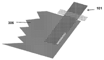
도 1 내지 도 4는 실시예에 따른 센서 부착 전극 탭을 도시하고 있다. 전극 탭(101)은 단일편 구성으로 일체화된 하나 이상의 센서(202), 기준 전극(204), 및 배터리 전극 인터페이스(206)와 같은 하나 이상의 특징부를 포함한다. 센서 부착 전극 탭(101)은 베이스 재료 위에 형성된 제1 외부층(110)을 포함한다. 외부층(110)은 폴리머 필름일 수도 있다. 다양한 실시예에서, 외부층(110)은 폴리이미드의 층을 포함하는 유전체 폴리머 필름이다. 외부층(110)은 배터리 전극 단자(102), 하나 이상의 센서 단자(104), 기준 전극 단자(106), 및 배터리 전극 인터페이스(108)를 노출하도록 베이스 재료 위에 형성될 수도 있다. 베이스 재료는 금속 또는 유전체 재료일 수도 있다.1 to 4 illustrate an electrode tab with a sensor according to an embodiment. The
배터리 전극 단자(102) 및 배터리 전극 인터페이스(108)는 배터리 전극과 인터페이싱한다. 다양한 실시예에서, 배터리 전극 인터페이스(108)는 조립된 배터리 내부에 포함되고 배터리 전극 단자(102)는 배터리 외부에 있다. 도 5 및 도 6에 도시되어 있는 바와 같이, 배터리 전극 인터페이스(108)는 구리 배터리 포일(306) 또는 배터리의 다른 구성요소에 접합된다. 하나 이상의 센서 단자(104)는 배터리에 대한 센서 정보에 액세스하는 것을 가능하게 하기 위해 전극 탭(101) 내에 포함된 하나 이상의 센서(202)를 전력 관리 시스템과 결합하도록 구성된다. 기준 전극 단자(106)는 배터리에 대한 센서 정보에 액세스하는 것을 가능하게 하기 위해 기준 전극(302)을 전력 관리 시스템과 결합하도록 구성된다. 다양한 실시예에서, 기준 전극(204)은 화학물, 전압, 및 다른 센서 정보를 제공하기 위해 조립된 배터리 내부에 위치되도록 구성된다.The
하나 이상의 센서(202)는, 다양한 실시예에 따르면, 베이스 재료 상에 형성된다. 다양한 실시예에서, 하나 이상의 센서(202)는 관련 기술 분야에 알려진 것들을 포함하는 퇴적 및 에칭 기술을 사용하여 전극 탭(101)의 베이스 재료 상에 형성된다. 다양한 실시예에서, 하나 이상의 센서(202)는 전극 탭(101)으로부터 분리되고 전극 탭(101)에 부착된 필름 상에 형성된다. 예를 들어, 하나 이상의 센서(202)는 필름 상에 형성되고 적층 기술 또는 접착제를 사용하여 전극 탭(101)에 부착된다. 아래의 도 7 및 도 9는 전극 탭(101)으로부터 분리된 필름 상에 형성된 하나 이상의 센서(202)를 갖는 실시예를 도시하고 있다.One or
몇몇 실시예의 경우, 센서(202)는 다수의 센서의 어레이로서 구성된다. 센서(202)는 하나 이상의 전기 트레이스에 연결되고 하나 이상의 센서 단자(104)와 전기적으로 결합된다. 센서 단자(104)는 전기 접점, 예를 들어 이들에 한정되는 것은 아니지만, 접촉 패드, 제로 삽입력 연결부, 또는 다른 회로와 전기 통신을 만드는 다른 방식을 포함할 수도 있다. 센서 단자는 센서(202)가 배터리 외부의 하나 이상의 회로와 전기 통신할 수 있도록, 몇몇 실시예에 따라, 외부층(102)을 넘어 연장하도록 구성된다. 하나 이상의 회로는 제어 회로 및 모니터링 회로를 포함할 수 있지만, 이들에 한정되지 않는다. 예를 들어, 배터리 외부의 하나 이상의 회로는 배터리의 성능을 최적화하도록 구성될 수 있다.For some embodiments,
전극 탭의 베이스 재료 상에 배치된 하나 이상의 센서(202)는 온도 센서, 스트레인 게이지, 및 커패시턴스 센서를 포함할 수 있지만, 이들에 한정되지 않는다. 스트레인 게이지는 배터리 내의 하나 이상의 섹션의 내부 압력 검출을 제공하도록 구성된다. 예를 들어, 하나 이상의 스트레인 게이지는 사용하여 배터리 팽창을 야기할 수 있는 배터리 내의 가스 발생을 결정하는 데 사용될 수 있다. 가스는 전해질의 전기화학적 산화로 인해 생성된다. 이러한 산화는 일반적으로 결함이 있는 배터리 또는 디바이스 또는 배터리 충전기의 결함이 있는 충전 전자 기기로 인한 배터리의 과충전으로 인해 발생한다. 커패시턴스 센서는 배터리 내의 하나 이상의 섹션의 내부 압력 검출을 제공하도록 구성된다. 커패시턴스 센서는 본 명세서에 설명된 바와 같이 배터리 내의 가스 발생을 결정하는 데 사용될 수 있다.The one or
온도 센서는 저항 온도 검출기, 열전쌍, 열전쌍열 및 서미스터를 포함하지만, 이들에 한정되는 것은 아니다. 온도 센서는 배터리 내에 형성된 배터리 셀의 하나 이상의 섹션의 온도 정보를 제공하도록 구성된다. 하나 이상의 유형의 센서는 몇몇 실시예에 따르면, 하나 이상의 유형의 센서가 배터리 셀 전극에 접촉하거나 근접한 배터리 셀의 상이한 섹션에 대한 정보를 제공하게 구성되도록 어레이로 형성된다. 다양한 실시예에서, 하나 이상의 센서는 신뢰성 및 증가된 에러 검출을 위해 이중이거나 용장성일 수 있다. 하나 이상의 센서는 일체형 저항기 또는 게이지, 예를 들어 이에 한정되는 것은 아니지만, 저항을 감지하는 휘트스톤 브리지 회로에 독립적으로 동작할 수 있다. 다양한 실시예에서, RTD와 같은 하나 이상의 센서는 배터리 성능을 개선하기 위해 배터리의 하나 이상의 영역을 워밍업하는 가열기로서 기능하도록 구성될 수도 있다.Temperature sensors include, but are not limited to, resistance temperature detectors, thermocouples, thermocouple columns, and thermistors. The temperature sensor is configured to provide temperature information of one or more sections of battery cells formed within the battery. The one or more types of sensors are formed in an array such that the one or more types of sensors are configured to provide information about different sections of a battery cell in contact with or proximate to a battery cell electrode, according to some embodiments. In various embodiments, one or more sensors may be redundant or redundant for reliability and increased error detection. The one or more sensors may operate independently of an integral resistor or gauge, such as, but not limited to, a Wheatstone bridge circuit sensing resistance. In various embodiments, one or more sensors, such as an RTD, may be configured to function as a heater to warm up one or more regions of the battery to improve battery performance.
통상의 기술자는 본 명세서에 설명된 하나 이상의 센서(202)가 화학적 감지, 생체 인식 감지, 연료 전지, 에너지 수확기, 약물 전달 디바이스, 마이크로유체 디바이스, 마이크로조작기, 마이크로액추에이터, 태양 전지, 및 유기 LED, LED 및 다른 디스플레이를 포함하는 다양한 용례에서 사용될 수 있다는 것을 인식할 수 있을 것이다. 하나 이상의 센서(202)는 특정 배터리 셀, 배터리, 또는 배터리 스택에 특정할 수도 있다. 배터리 스택의 각각의 배터리의 배터리 셀에 하나 이상의 센서를 갖는 전극 탭을 포함하는 것은 배터리 스택 내의 각각의 셀의 성능을 나타내는 센서 정보에 대한 액세스를 가능하게 함으로써 배터리 스택 성능의 분해능을 증가시킬 수 있다.One of ordinary skill in the art would be aware that one or more of the
다양한 실시예에서, 하나 이상의 센서(202)는 기준 전극(302)과 일체화될 수 있다. 기준 전극(302)은 배터리 전극 및/또는 집전체로부터 전기적으로 절연되도록 구성되고 배터리에 포함된 전해질과 화학적으로 매칭하도록 제조될 수도 있다. 다양한 실시예에서, 기준 전극(302)은 기준 전극이 배터리 셀에 직접적으로 단락되는 것을 방지하기 위해 배터리 전극 인터페이스(108)에 대향하는 전극 탭의 이면에서 노출되도록 구성된다. 기준 전극(302)은 예를 들어, 베이스 재료의 에칭, 레이저 어블레이션 등에 의해 및/또는 유전체 층, 예를 들어 폴리이미드 층의 퇴적에 의해 노출될 수도 있다.In various embodiments, one or
기준 전극은 전도성 금속, 예를 들어 구리, 니켈 도금 구리 등일 수도 있다. 다양한 실시예에서, 기준 전극(302)은 대안적인 금속 및/또는 금속 산화물 물질, 예를 들어 금, 은, 백금, 이리듐, 이리듐 산화물(IrOX), 알루미늄 등으로 도금될 수도 있다. 기준 전극은 리튬 금속 산화물 조성(LiMOx), 예를 들어 리튬 코발트 산화물(LiCoO2), 리튬 철 인산염(FeLiO4P) 등으로 도금될 수도 있다. 기준 전극(302)은 배터리 내부에 조립될 수도 있고 배터리 셀에 대한 화학 센서 정보에 액세스하는 것을 가능하게 하기 위해 전해질과 접촉할 수도 있다. 화학 센서 정보는 전해질 또는 전해질로부터 전기화학적으로 합성될 수도 있는 물질의 조성과 매칭하는 기준 상에 퇴적된 필름 또는 다른 물질의 존재 및/또는 특성을 포함할 수도 있다. 다양한 실시예에서, 기준 전극(302)은 내부 배터리 저항 및/또는 임피던스를 감지하기 위해 기준 전극(302)에 전류를 전달하기 위한 상대 전극을 포함한다.The reference electrode may be a conductive metal, such as copper, nickel plated copper, or the like. In various embodiments, the
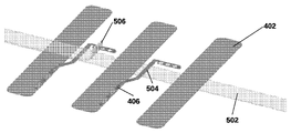
도 7은 일 실시예에 따른 센서 부착 전극 탭을 도시하고 있다. 센서 부착 전극 탭은 전극(402)에 고정된 하나 이상의 센서(406)를 포함한다. 전극(402)은 얇은 금속 전극, 예를 들어 니켈 또는 구리 전극이다. 다양한 실시예에서, 구리 전극은 구리보다 덜 전도성인 금속, 예를 들어 니켈로 도금될 수도 있다. 몇몇 실시예에 따르면, 전극(402)은 2 내지 10 mm 폭 및 50 내지 200 미크론(㎛) 두께이다. 다양한 실시예에서, 전극(402)은 6 mm 폭 및 80 ㎛ 두께이다. 전극(402)은 전극(402)을 배터리에 부착하기 위한 하나 이상의 구역을 포함할 수도 있다. 다양한 실시예에서, 전극은 열, 예를 들어 초음파 접합, 레이저 용접 등을 사용하여 전극을 구리 포일에 접합함으로써 배터리에 부착된다.7 illustrates an electrode tab with a sensor according to an embodiment. The sensor-attached electrode tab includes one or
도 8은 실시예에 따른 온도 센서를 도시하고 있다. 온도 센서(406)는 하나 이상의 전기 트레이스와 전기적으로 결합된 저항 온도 검출기로서 구성된다. 온도 센서(406)는 폴리머 필름 상에 배치된 사행형 라인으로서 구성된다. 다양한 실시예에서, 사행형 라인은 사행형 라인의 제1 단부에서 제1 전기 트레이스와 전기적으로 결합되고 사행형 라인의 제2 단부에서 제2 전기 트레이스와 전기적으로 결합된다. 온도 센서(406)는 배터리 외부의 하나 이상의 회로와 인터페이싱할 수도 있는 하나 이상의 센서 단자(408)에 연결된다. 다양한 실시예에서, 온도 센서는 동일한 온도를 유지하기 위해 짜맞춰진 2개 이상의 저항 온도 검출기(RTD)를 갖는 용장성 RTD일 수도 있다. 용장성 RTD는 온도 센서 내의 에러를 검출하는 데 사용할 수도 있고, 예를 들어 2개의 RTD 사이의 불일치는 센서 고장으로서 해석될 수도 있고, 배터리의 성능은 배터리 동작에 관한 온도 종속 문제를 회피하기 위해 변경될 수도 있다. 예를 들어, 충전율이 감소될 수도 있다.8 shows a temperature sensor according to an embodiment. The
온도 센서(406)는 열, 예를 들어 초음파 접합, 레이저 용접 등을 사용하여 구조적으로 전극(402)에 부착될 수도 있다. 선택적으로, 온도 센서(406)는 또한 접합 접착제를 사용하여 전극(402)에 부착될 수도 있다. 예를 들어, 고온 용융 필름(404)이 온도 센서 회로와 전극의 접합 표면에 도포된다.The
도 9에 도시되어 있는 바와 같이, 온도 센서는 센서 회로의 단부에 부착된 하나 이상의 동일 평면 센서 단자를 갖는 직선형 센서(602)일 수도 있다. 전극 상에 센서를 적층하는 것을 회피하여, 이에 의해 센서의 결과로서 전극 두께의 임의의 변화를 최소화하고 그리고/또는 패널 제조 장치를 위한 센서 밀도를 최대화한다. 다양한 실시예에서, 센서(406)는 전극(402)과 동일 평면에 있고 그리고/또는 전극(402)에 구조적으로 독립적으로 구성될 수도 있다. 센서(406)는 패널로부터 절단될 수도 있고 고온 용융 테이프를 사용하여 전극에 조립될 수도 있다. 도 12는 몇몇 실시예에 따른 센서의 패널을 도시하고 있다. 선택적으로, 센서는 도 11에 도시되어 있는 바와 같이 전극에 독립적인 독립형 센서 디바이스일 수도 있다.As shown in FIG. 9 , the temperature sensor may be a
도 10은 도 7의 센서 부착 배터리 탭을 형성하기 위한 프로세스를 도시하고 있다. 전극(402)은 연속 조립 프로세스에서 릴로부터 교차 공급될 수도 있다. 전극(402)은 릴로부터 절단되고 열을 사용하여 제1 밀봉 테이프(502)에 접합된다. 센서(406)는 이어서 전극 위에 온도 센서가 있는 상태로 전극 상에 배치되고 센서 회로(504)는 열을 사용하여 제1 테이프에 부착된다. 밀봉 테이프(506)의 제2 층은 이어서 열, 예를 들어 열간 압연 적층을 사용하여 전극(402) 및 센서 회로(504)에 고정된다. 다양한 실시예에서, 밀봉 테이프의 제1 및 제2 층은 연속 롤에서 처리되는 5 밀리미터(mm) 폭의 고온 용융 테이프이다.FIG. 10 depicts a process for forming the sensored battery tab of FIG. 7 .
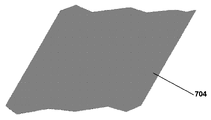
도 13 내지 도 23은 본 개시내용의 몇몇 실시예에 따른 애노드 탭(702)을 형성하는 방법을 설명하고 있다. 도 14를 참조하면, 베이스 재료의 롤(604)이 제공된다. 몇몇 실시예의 경우, 베이스 재료(604)는 니켈보다 더 높은 전도성을 갖는 재료이다. 몇몇 실시예의 경우, 베이스 재료(604)는 구리 포일이다. 몇몇 실시예의 경우, 구리 포일은 폴리이미드 코팅의 직접 접합을 지원하기 위해 크로메이트 처리되어 있다. 구리 포일은 20 내지 50 ㎛의 두께를 가질 수 있다. 몇몇 실시예의 경우, 구리 포일은 35 ㎛의 두께를 가질 수 있다.13-23 illustrate a method of forming an
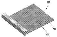
도 15는 베이스 재료(704) 상에 배치된 폴리이미드 코팅(706)과 같은 유전체 층을 도시하고 있다. 몇몇 실시예의 경우, 폴리이미드 코팅(706)은 베이스 재료(704)의 포일 측(710)이 아니라, 베이스 재료(704)의 분리막 측(708)에만 배치된다. 몇몇 실시예의 경우, 폴리이미드 코팅(706)은 애노드 탭(702)의 두께를 최소화하기 위해 5 내지 10 ㎛의 두께로 도포될 수 있다. 폴리이미드 코팅(706)은 이들에 한정되는 것은 아니지만, 액체 슬롯 다이, 롤러 코트(roller coat), 스프레이, 커튼 코트(curtain coat), 건식 필름 적층 및 스크린 인쇄 기술을 포함하는 기술을 사용하여 도포된다. 몇몇 실시예의 경우, 폴리이미드 코팅(706)은 액체 슬롯 다이 퇴적에 의해 도포된다. 몇몇 실시예에 따르면, 폴리이미드 코팅(706)은 광이미징 가능 폴리이미드이고 자외선(UV) 광에 노광되고, 현상되고, 경화된다.15 shows a dielectric layer, such as
도 16은 패턴(712)이 그 위에 에칭되어 있는 베이스 재료(704)의 분리막 측(708) 상에 배치된 폴리이미드 코팅을 도시하고 있다. 폴리이미드 코팅(706) 상에 에칭된 패턴(712)은 기준 전극 단자(714), RTD 단자(716), 기준 전극(718), 및 메인 애노드 단자(720)에 대한 액세스 지점을 포함한다.16 shows a polyimide coating disposed on the
몇몇 실시예의 경우, 폴리이미드 코팅(706) 상에 패턴(712)을 형성하기 위해, 포토레지스트 층이 폴리이미드 코팅(706) 상에 형성된다. 포토레지스트 층은 몇몇 실시예에 따르면, 관련 기술 분야에 알려진 것들을 포함하는 포토리소그래피 기술을 사용하여 노광되고 관련 기술 분야에 알려진 것들을 포함하는 습식 에칭 기술을 사용하여 현상된다. 이 패터닝된 포토레지스트 층은 이어서 폴리이미드 제거 프로세스(에칭) 동안 폴리이미드 코팅(706)을 위한 패턴을 제공하는데, 습식 또는 건식 기술이 사용될 수 있다. 포토레지스트 층은 이어서 관련 기술 분야에 알려진 기술에 의해 박리될 수 있다. 또 다른 패터닝 방법은 원하지 않는 유전체의 레이저 어블레이션이다.For some embodiments, a photoresist layer is formed on the
도 17은 베이스 재료(704)의 포일 측(724) 상에 에칭된 패턴(722)을 도시하고 있다. 몇몇 실시예의 경우, 패턴(722)이 그 위에 에칭된 후에 애노드 탭(702)은 메인 애노드(726), 2개의 RTD 리드(728), 및 기준 전극 리드(728)를 가질 것이다.17 shows an
몇몇 실시예의 경우, 베이스 재료(704)의 포일 측(724)의 패턴(722)을 에칭하기 위해, 방법은 레지스트 층을 코팅하는 단계, 레지스트 층을 UV 광에 노출하는 단계, 레지스트 층을 현상하는 단계, 베이스 재료를 에칭하는 단계, 및 레지스트 층을 박리하는 단계를 더 포함한다. 레지스트 코팅이 이들에 한정되는 것은 아니지만, 액체 슬롯 다이, 롤러 코트, 스프레이, 커튼 코트, 건식 필름 적층 및 스크린 인쇄 기술을 포함하는 기술을 사용하여 베이스 재료(704) 상에 도포된다. 레지스트 코팅은 이어서 포토리소그래피 및 관련 기술 분야에 알려진 것들을 포함하는 에칭 기술을 사용하여 UV 광에 노광되고, 현상되고, 에칭되고(즉, 베이스 재료(704)는 레지스트 패턴에 의해 보호되지 않는 영역에서 에칭됨), 박리된다.For some embodiments, to etch the
몇몇 실시예의 경우, 방법은 크로메이트 처리를 제거하기 위해 애노드 탭(702)을 마이크로 에칭하는 단계를 더 포함한다. 마이크로 에칭은 산화 프로세스를 사용하여 또는 관련 기술 분야에 알려진 다른 기술에 의해 수행될 수 있다.For some embodiments, the method further includes micro-etching the
도 18은 베이스 재료(702)의 포일 측(724)의 노출된 구리 위에 배치된 니켈 층(730)을 도시하고 있다. 몇몇 실시예의 경우, 방법은 포일 측(724)의 니켈을 스퍼터링하는 단계를 포함한다. 몇몇 실시예의 경우, 니켈 층(730)은 약 1 내지 5 ㎛ 두께이다. 바람직하게는, 니켈 층(730)은 약 2 ㎛ 두께이다. 포일 측(724)의 니켈을 스퍼터링하는 단계는 관련 기술 분야에 잘 알려진 기술을 사용하여 수행될 수 있다.18 shows a
도 19는 니켈 층(730) 내의 에칭된 패턴(732)을 도시하고 있다. 몇몇 실시예의 경우, 니켈 층(730) 상에 패턴(732)을 에칭하기 위해, 방법은 레지스트 층을 코팅하는 단계, 레지스트 층을 UV 광에 노출하는 단계, 레지스트 층을 현상하는 단계, 베이스 재료를 에칭하는 단계, 및 레지스트 층을 박리하는 단계를 더 포함한다. 레지스트 코팅이 이들에 한정되는 것은 아니지만, 액체 슬롯 다이, 롤러 코트, 스프레이, 커튼 코트, 건식 필름 적층 및 스크린 인쇄 기술을 포함하는 기술을 사용하여 니켈 층(730) 상에 도포된다. 레지스트 코팅은 이어서 포토리소그래피 및 관련 기술 분야에 알려진 것들을 포함하는 에칭 기술을 사용하여 UV 광에 노광되고, 현상되고, 에칭되고(즉, 니켈 층(730)은 레지스트 패턴에 의해 보호되지 않는 영역에서 에칭됨), 박리된다.19 shows an
도 20은 패턴(736)이 그 위에 에칭되어 있는 포일 측(724) 위에 배치된 폴리이미드 층(734)과 같은 제2 유전체 층을 도시하고 있다. 몇몇 실시예의 경우, 폴리이미드 코팅(734)은 애노드 탭(702)의 두께를 최소화하기 위해 5 내지 10 ㎛의 두께로 도포될 수 있다. 제2 폴리이미드 코팅(734)은 이들에 한정되는 것은 아니지만, 액체 슬롯 다이, 롤러 코트, 스프레이, 커튼 코트, 건식 필름 적층 및 스크린 인쇄 기술을 포함하는 기술을 사용하여 도포된다. 몇몇 실시예의 경우, 제2 폴리이미드 코팅(46)은 액체 슬롯 다이에 의해 도포된다. 몇몇 실시예에 따르면, 제2 폴리이미드 코팅(734)은 광이미징 가능 폴리이미드이고 UV 광에 노광되고, 현상되고, 경화된다. 제2 폴리이미드 코팅(734) 상에 에칭된 패턴(736)은 4개의 핀 아웃(pin outs)(738) 및 메인 포일 부착면(740)에 대한 액세스 지점을 포함한다. 패턴(736)은 본 개시내용에서 설명된 기술 또는 관련 기술 분야에 알려진 다른 기술에 의해 에칭될 수 있다.20 shows a second dielectric layer, such as
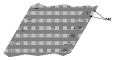
도 21은 애노드 탭(702) 상의 전기도금된 니켈 층(742)을 도시하고 있다. 몇몇 실시예에서, 방법은 애노드 탭(702)의 양 측(즉, 포일 측 및 분리막 측)에 니켈을 전기도금하는 단계를 포함한다. 몇몇 실시예의 경우, 니켈 층(742)은 연질 니켈이고 애노드 탭(702)의 모든 노출된 니켈면을 커버한다. 몇몇 실시예의 경우, 니켈 층(742)은 약 1 내지 5 ㎛ 두께이다. 바람직하게는, 니켈 층(742)은 약 2 내지 3 ㎛ 두께이다. 애노드 탭(702) 상에 니켈을 전기도금하는 단계는 마스크 없이 관련 기술 분야에 잘 알려진 기술을 사용하여 수행될 수 있다.21 shows an electroplated
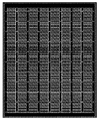
도 22는 패널화되고, 자동 광학 검사(AOI) 검사되고, 결함 마킹되는 애노드 탭(702)을 도시하고 있다. 이러한 단계들은 관련 기술 분야에 잘 알려진 기술을 사용하여 수행될 수 있다.22 shows an
또한, 방법은 기준 전극 재료(744)를 선택적으로 도포하는 단계를 포함할 수 있다. 몇몇 실시예의 경우, 흑연 슬러리 재료의 얇은 코팅이 잉크젯, 제트, 주사기 분배, 스텐실, 및 관련 기술 분야에 알려진 다른 유사한 기술에 의해, 노출된 기준 전극(746)에 선택적으로 도포된다. 방법은 또한 기준 전극 재료(744)를 선택적으로 도포한 후에 애노드 탭(702)을 베이킹하는 단계를 더 포함할 수 있다. 베이킹은 관련 기술 분야에 알려진 조건에서 수행될 수 있다.The method may also include selectively applying a
도 23은 애노드 탭(702)의 단축 상에서 밀봉재(748)가 그 위에 도포되어 있는 애노드 탭(702)을 도시하고 있다. 몇몇 실시예의 경우, 방법은 애노드 탭(702)을 싱귤레이팅(singulating)하고 그 위에 밀봉재(748)를 도포하는 단계를 포함한다. 밀봉재(748)는 애노드 탭(702)의 제1 측 및 제2 측에서 애노드 탭(702)의 단축을 따라 도포될 수 있다. 몇몇 실시예의 경우, 밀봉재(748)는 열 밀봉 테이프이다. 관련 기술 분야에 알려진 다른 밀봉재가 또한 사용될 수 있다.23 shows the
애노드 탭(702)을 형성하기 위한 방법과 동일한 유사한 캐소드 탭을 형성하기 위한 방법이 수행될 수 있다. 통상의 기술자는 애노드 탭(702)을 형성하기 위한 방법에 기초하여 캐소드 탭을 제조하기 위한 변형예를 즉시 이해할 수 있을 것이다. 예를 들어, RTD는 기준 전극으로 교체되고 리튬 산화물 재료와 같은 상이한 슬러리 재료가 기준 전극 상에 도포될 것이다. 몇몇 실시예의 경우, 캐소드 탭을 위한 베이스 층은 알루미늄이다.A method for forming the cathode tab similar to the method for forming the
이들 실시예와 관련하여 설명되었지만, 통상의 기술자는 본 발명의 사상 및 범주로부터 벗어나지 않고 변경이 형태 및 상세에 이루어질 수 있다는 것을 인식할 수 있을 것이다.Although described in connection with these embodiments, those skilled in the art will recognize that changes may be made in form and detail without departing from the spirit and scope of the present invention.
Claims (20)
센서를 포함하는 베이스 층을 포함하는, 전극 탭.electrode tab,
An electrode tab comprising a base layer comprising a sensor.
배터리 전극; 및
배터리 전극에 부착된 센서를 포함하는, 전극 탭.electrode tab,
battery electrode; and
An electrode tab comprising a sensor attached to a battery electrode.
외부층; 및
베이스 층 상에 형성된 외부층을 갖는 베이스 층으로서, 베이스 층은 베이스 층 상에 형성된 하나 이상의 기준 전극을 포함하는, 베이스 층을 포함하는, 전극 탭.electrode tab,
outer layer; and
An electrode tab comprising a base layer having an outer layer formed on the base layer, the base layer comprising one or more reference electrodes formed on the base layer.
Applications Claiming Priority (7)
| Application Number | Priority Date | Filing Date | Title |
|---|---|---|---|
| US201962900419P | 2019-09-13 | 2019-09-13 | |
| US62/900,419 | 2019-09-13 | ||
| US201962901162P | 2019-09-16 | 2019-09-16 | |
| US62/901,162 | 2019-09-16 | ||
| US17/017,523 | 2020-09-10 | ||
| US17/017,523 US11322806B2 (en) | 2019-09-13 | 2020-09-10 | Sensored battery electrode |
| PCT/US2020/050561 WO2021050999A1 (en) | 2019-09-13 | 2020-09-11 | Sensored battery electrode |
Publications (1)
| Publication Number | Publication Date |
|---|---|
| KR20220061188A true KR20220061188A (en) | 2022-05-12 |
Family
ID=74865924
Family Applications (1)
| Application Number | Title | Priority Date | Filing Date |
|---|---|---|---|
| KR1020227011703A KR20220061188A (en) | 2019-09-13 | 2020-09-11 | battery electrode with sensor |
Country Status (6)
| Country | Link |
|---|---|
| US (1) | US11322806B2 (en) |
| EP (1) | EP4029073A4 (en) |
| JP (1) | JP2022548860A (en) |
| KR (1) | KR20220061188A (en) |
| CN (1) | CN114730904A (en) |
| WO (1) | WO2021050999A1 (en) |
Families Citing this family (3)
| Publication number | Priority date | Publication date | Assignee | Title |
|---|---|---|---|---|
| US11791521B2 (en) | 2019-09-13 | 2023-10-17 | Hutchinson Technology Incorporated | Electrode tabs and methods of forming |
| CN113097590B (en) * | 2021-04-01 | 2022-10-14 | 电子科技大学 | Lithium battery current collector with temperature sensing function and preparation method thereof |
| CN113432742A (en) * | 2021-06-22 | 2021-09-24 | 上海科技大学 | Resistance type temperature sensor and preparation method and application thereof |
Family Cites Families (33)
| Publication number | Priority date | Publication date | Assignee | Title |
|---|---|---|---|---|
| US6379865B1 (en) | 2000-04-11 | 2002-04-30 | 3M Innovative Properties Company | Photoimageable, aqueous acid soluble polyimide polymers |
| US8133604B1 (en) | 2006-04-05 | 2012-03-13 | Hiroshi Nakahara | Electrochemical device assembly having electrode tabs connected to a clad spacer |
| EP2260524B1 (en) * | 2008-03-24 | 2020-01-08 | Lightening Energy | A modular battery, an interconnector for such batteries and methods related to modular batteries |
| KR101093612B1 (en) * | 2008-11-12 | 2011-12-15 | 전자부품연구원 | The capacitance type humidity sensor and fabrication method thereof |
| DE102010046307B4 (en) * | 2010-09-15 | 2018-04-12 | Fraunhofer-Gesellschaft zur Förderung der angewandten Forschung e.V. | Electrochemical cell of a rechargeable battery |
| EP2442400A1 (en) | 2010-10-13 | 2012-04-18 | Fraunhofer-Gesellschaft zur Förderung der angewandten Forschung e.V. | Electrochemical cell based on lithium technology with internal reference electrode, process for its production and methods for simultaneous monitoring the voltage or impedance of the anode and the cathode thereof |
| US8828570B2 (en) | 2011-06-29 | 2014-09-09 | Hewlett-Packard Development Company, L.P. | Battery temperature sensor |
| KR20130061979A (en) * | 2011-12-02 | 2013-06-12 | 삼성에스디아이 주식회사 | Rechargeable battery pack |
| CN102496750B (en) * | 2011-12-20 | 2014-10-08 | 华为技术有限公司 | Battery |
| JP5978718B2 (en) * | 2012-03-30 | 2016-08-24 | 三菱マテリアル株式会社 | Battery with temperature control function |
| DE102012209271A1 (en) * | 2012-06-01 | 2013-12-05 | Robert Bosch Gmbh | Battery management system for a battery cell with pressure-sensitive film sensor |
| US9203122B2 (en) * | 2012-09-28 | 2015-12-01 | Palo Alto Research Center Incorporated | Monitoring and management for energy storage devices |
| KR101547403B1 (en) | 2013-01-11 | 2015-08-25 | 주식회사 엘지화학 | Secondary battery comprising unified positive lead and negative lead and the method for preparing thereof |
| US10292263B2 (en) | 2013-04-12 | 2019-05-14 | The Board Of Trustees Of The University Of Illinois | Biodegradable materials for multilayer transient printed circuit boards |
| KR101577387B1 (en) | 2013-05-06 | 2015-12-16 | 주식회사 엘지화학 | Secondary battery, and secondary battery module and secondary battery pack comprising the same |
| JP2014225406A (en) * | 2013-05-17 | 2014-12-04 | 本田技研工業株式会社 | Humidity measuring device for fuel cell |
| US9419313B2 (en) * | 2013-10-18 | 2016-08-16 | Ford Global Technologies, Llc | Lithium battery with reference electrode plated on an interior surface of a neutral metal can |
| US10211443B2 (en) | 2014-09-10 | 2019-02-19 | Cellink Corporation | Battery interconnects |
| CN107405084B (en) | 2014-12-31 | 2021-11-19 | 蓝色火花科技有限公司 | Body temperature recording patch |
| CN104900932A (en) * | 2015-04-23 | 2015-09-09 | 四川长虹电源有限责任公司 | Novel lithium-ion storage battery |
| WO2017087807A1 (en) | 2015-11-19 | 2017-05-26 | The Regents Of The University Of Michigan | State of battery health estimation based on swelling characteristics |
| TWI719110B (en) | 2016-01-15 | 2021-02-21 | 日商Jx金屬股份有限公司 | Manufacturing methods of copper foil, copper-clad laminates, printed wiring boards, manufacturing methods of electronic devices, manufacturing methods of transmission lines, and manufacturing methods of antennas |
| WO2017136719A1 (en) * | 2016-02-03 | 2017-08-10 | Hutchinson Technology Incorporated | Miniature pressure/force sensor with integrated leads |
| CN106159364B (en) * | 2016-08-29 | 2019-06-14 | 淄博火炬能源有限责任公司 | The on-line monitoring method and device of rectangular lithium ion battery internal temperature |
| US10714795B2 (en) * | 2017-05-01 | 2020-07-14 | Infineon Technologies Ag | Monitoring battery cell internal pressure |
| CN107026282A (en) * | 2017-06-02 | 2017-08-08 | 中天储能科技有限公司 | A kind of lithium ion battery three-electrode system and its method of testing |
| IN201741021696A (en) | 2017-06-21 | 2018-12-28 | ||
| KR102175734B1 (en) * | 2018-01-24 | 2020-11-06 | 주식회사 아모그린텍 | Sensor for detecting the pressure of battery and device having the same |
| US11355824B2 (en) * | 2018-05-11 | 2022-06-07 | The Regents Of The University Of Michigan | Detection of an internal short circuit in a battery |
| CN108987659A (en) * | 2018-06-26 | 2018-12-11 | 桑顿新能源科技有限公司 | A kind of four electrode system of lithium ion soft-package battery and preparation method thereof |
| CN109065961B (en) * | 2018-08-09 | 2020-07-24 | 北京理工大学 | Manufacturing method of multi-point internal temperature monitoring integrated battery |
| US20200076016A1 (en) | 2018-09-04 | 2020-03-05 | Hutchinson Technology Incorporated | Sensored Battery Pouch |
| US11791521B2 (en) | 2019-09-13 | 2023-10-17 | Hutchinson Technology Incorporated | Electrode tabs and methods of forming |
-
2020
- 2020-09-10 US US17/017,523 patent/US11322806B2/en active Active
- 2020-09-11 WO PCT/US2020/050561 patent/WO2021050999A1/en unknown
- 2020-09-11 EP EP20862151.6A patent/EP4029073A4/en active Pending
- 2020-09-11 JP JP2022516167A patent/JP2022548860A/en active Pending
- 2020-09-11 CN CN202080078776.9A patent/CN114730904A/en active Pending
- 2020-09-11 KR KR1020227011703A patent/KR20220061188A/en unknown
Also Published As
| Publication number | Publication date |
|---|---|
| WO2021050999A1 (en) | 2021-03-18 |
| JP2022548860A (en) | 2022-11-22 |
| EP4029073A4 (en) | 2023-10-18 |
| US20210083258A1 (en) | 2021-03-18 |
| CN114730904A (en) | 2022-07-08 |
| EP4029073A1 (en) | 2022-07-20 |
| US11322806B2 (en) | 2022-05-03 |
Similar Documents
| Publication | Publication Date | Title |
|---|---|---|
| US20200076016A1 (en) | Sensored Battery Pouch | |
| US11322806B2 (en) | Sensored battery electrode | |
| JP6198804B2 (en) | Strain sensor for multipoint measurement and its manufacturing method | |
| US20150255834A1 (en) | Battery cell with integrated sensing platform | |
| JP5494967B2 (en) | Battery with temperature sensor | |
| EP1398297A2 (en) | Electronic component with carbon nanotube interconnects and method of manufacturing the same | |
| CN1199467A (en) | Condition tester for battery | |
| US9291543B1 (en) | PC board mount corrosion sensitive sensor | |
| CN115266848A (en) | Multi-channel gas sensor and preparation method thereof | |
| JP4586413B2 (en) | Fuel cell | |
| WO2021050997A2 (en) | Electrode tabs and methods of forming | |
| JP2886343B2 (en) | Method of manufacturing parts on metal film base | |
| US20210247218A1 (en) | Systems And Methods To Increase Sensor Robustness | |
| KR100516774B1 (en) | Pouch type Lithium secondary battery | |
| US10608454B2 (en) | Electrochemical device, such as a microbattery, and fabrication method thereof | |
| CN114295160B (en) | Flexible sensing array for monitoring multiple physical fields in lithium battery | |
| JP7488279B2 (en) | Two-part reference electrode | |
| CN107256746A (en) | The manufacture method and chip type thermal resistor of chip type thermal resistor | |
| KR20230122615A (en) | Battery cell and battery having means for detecting state of health (SoH) and state of charge (SoC) | |
| JP2001056257A (en) | Temperature sensor element, manufacture thereof and temperature sensor | |
| CN114122540B (en) | Temperature detector, preparation method thereof and lithium battery structure combination | |
| US20240060921A1 (en) | Flexible PH Sensor and Improved Methods of Manufacture | |
| KR101237962B1 (en) | Multi-function sensor and manufacturing method thereof | |
| CN117769125A (en) | Flexible circuit board and manufacturing method thereof | |
| CN106953106B (en) | Microbattery design and diagnostics |