KR20220050902A - Damping valve device with gradual damping force characteristic curve - Google Patents
Damping valve device with gradual damping force characteristic curve Download PDFInfo
- Publication number
- KR20220050902A KR20220050902A KR1020227006255A KR20227006255A KR20220050902A KR 20220050902 A KR20220050902 A KR 20220050902A KR 1020227006255 A KR1020227006255 A KR 1020227006255A KR 20227006255 A KR20227006255 A KR 20227006255A KR 20220050902 A KR20220050902 A KR 20220050902A
- Authority
- KR
- South Korea
- Prior art keywords
- valve
- damping
- pressure control
- control valve
- ring element
- Prior art date
Links
- 238000013016 damping Methods 0.000 title claims abstract description 60
- 230000001105 regulatory effect Effects 0.000 claims description 3
- 230000000694 effects Effects 0.000 description 5
- 238000004519 manufacturing process Methods 0.000 description 4
- 238000007789 sealing Methods 0.000 description 4
- 238000010276 construction Methods 0.000 description 3
- 238000000034 method Methods 0.000 description 2
- 229920000742 Cotton Polymers 0.000 description 1
- 230000004323 axial length Effects 0.000 description 1
- 230000000903 blocking effect Effects 0.000 description 1
- 230000006835 compression Effects 0.000 description 1
- 238000007906 compression Methods 0.000 description 1
- 230000007423 decrease Effects 0.000 description 1
- 230000001627 detrimental effect Effects 0.000 description 1
- 238000010586 diagram Methods 0.000 description 1
- 229920001971 elastomer Polymers 0.000 description 1
- 239000000806 elastomer Substances 0.000 description 1
- 239000013536 elastomeric material Substances 0.000 description 1
- 238000001746 injection moulding Methods 0.000 description 1
- 239000000463 material Substances 0.000 description 1
- 239000002184 metal Substances 0.000 description 1
- 230000003534 oscillatory effect Effects 0.000 description 1
- 230000010412 perfusion Effects 0.000 description 1
- 230000000750 progressive effect Effects 0.000 description 1
Images


Classifications
-
- F—MECHANICAL ENGINEERING; LIGHTING; HEATING; WEAPONS; BLASTING
- F16—ENGINEERING ELEMENTS AND UNITS; GENERAL MEASURES FOR PRODUCING AND MAINTAINING EFFECTIVE FUNCTIONING OF MACHINES OR INSTALLATIONS; THERMAL INSULATION IN GENERAL
- F16F—SPRINGS; SHOCK-ABSORBERS; MEANS FOR DAMPING VIBRATION
- F16F9/00—Springs, vibration-dampers, shock-absorbers, or similarly-constructed movement-dampers using a fluid or the equivalent as damping medium
- F16F9/32—Details
- F16F9/50—Special means providing automatic damping adjustment, i.e. self-adjustment of damping by particular sliding movements of a valve element, other than flexions or displacement of valve discs; Special means providing self-adjustment of spring characteristics
- F16F9/512—Means responsive to load action, i.e. static load on the damper or dynamic fluid pressure changes in the damper, e.g. due to changes in velocity
-
- F—MECHANICAL ENGINEERING; LIGHTING; HEATING; WEAPONS; BLASTING
- F16—ENGINEERING ELEMENTS AND UNITS; GENERAL MEASURES FOR PRODUCING AND MAINTAINING EFFECTIVE FUNCTIONING OF MACHINES OR INSTALLATIONS; THERMAL INSULATION IN GENERAL
- F16F—SPRINGS; SHOCK-ABSORBERS; MEANS FOR DAMPING VIBRATION
- F16F9/00—Springs, vibration-dampers, shock-absorbers, or similarly-constructed movement-dampers using a fluid or the equivalent as damping medium
- F16F9/32—Details
- F16F9/34—Special valve constructions; Shape or construction of throttling passages
- F16F9/348—Throttling passages in the form of annular discs or other plate-like elements which may or may not have a spring action, operating in opposite directions or singly, e.g. annular discs positioned on top of the valve or piston body
-
- F—MECHANICAL ENGINEERING; LIGHTING; HEATING; WEAPONS; BLASTING
- F16—ENGINEERING ELEMENTS AND UNITS; GENERAL MEASURES FOR PRODUCING AND MAINTAINING EFFECTIVE FUNCTIONING OF MACHINES OR INSTALLATIONS; THERMAL INSULATION IN GENERAL
- F16F—SPRINGS; SHOCK-ABSORBERS; MEANS FOR DAMPING VIBRATION
- F16F2230/00—Purpose; Design features
- F16F2230/42—Multiple pistons
-
- F—MECHANICAL ENGINEERING; LIGHTING; HEATING; WEAPONS; BLASTING
- F16—ENGINEERING ELEMENTS AND UNITS; GENERAL MEASURES FOR PRODUCING AND MAINTAINING EFFECTIVE FUNCTIONING OF MACHINES OR INSTALLATIONS; THERMAL INSULATION IN GENERAL
- F16F—SPRINGS; SHOCK-ABSORBERS; MEANS FOR DAMPING VIBRATION
- F16F9/00—Springs, vibration-dampers, shock-absorbers, or similarly-constructed movement-dampers using a fluid or the equivalent as damping medium
- F16F9/32—Details
- F16F9/34—Special valve constructions; Shape or construction of throttling passages
- F16F9/348—Throttling passages in the form of annular discs or other plate-like elements which may or may not have a spring action, operating in opposite directions or singly, e.g. annular discs positioned on top of the valve or piston body
- F16F9/3482—Throttling passages in the form of annular discs or other plate-like elements which may or may not have a spring action, operating in opposite directions or singly, e.g. annular discs positioned on top of the valve or piston body the annular discs being incorporated within the valve or piston body
-
- F—MECHANICAL ENGINEERING; LIGHTING; HEATING; WEAPONS; BLASTING
- F16—ENGINEERING ELEMENTS AND UNITS; GENERAL MEASURES FOR PRODUCING AND MAINTAINING EFFECTIVE FUNCTIONING OF MACHINES OR INSTALLATIONS; THERMAL INSULATION IN GENERAL
- F16F—SPRINGS; SHOCK-ABSORBERS; MEANS FOR DAMPING VIBRATION
- F16F9/00—Springs, vibration-dampers, shock-absorbers, or similarly-constructed movement-dampers using a fluid or the equivalent as damping medium
- F16F9/32—Details
- F16F9/34—Special valve constructions; Shape or construction of throttling passages
- F16F9/348—Throttling passages in the form of annular discs or other plate-like elements which may or may not have a spring action, operating in opposite directions or singly, e.g. annular discs positioned on top of the valve or piston body
- F16F9/3488—Throttling passages in the form of annular discs or other plate-like elements which may or may not have a spring action, operating in opposite directions or singly, e.g. annular discs positioned on top of the valve or piston body characterised by features intended to affect valve bias or pre-stress
-
- F—MECHANICAL ENGINEERING; LIGHTING; HEATING; WEAPONS; BLASTING
- F16—ENGINEERING ELEMENTS AND UNITS; GENERAL MEASURES FOR PRODUCING AND MAINTAINING EFFECTIVE FUNCTIONING OF MACHINES OR INSTALLATIONS; THERMAL INSULATION IN GENERAL
- F16F—SPRINGS; SHOCK-ABSORBERS; MEANS FOR DAMPING VIBRATION
- F16F9/00—Springs, vibration-dampers, shock-absorbers, or similarly-constructed movement-dampers using a fluid or the equivalent as damping medium
- F16F9/32—Details
- F16F9/50—Special means providing automatic damping adjustment, i.e. self-adjustment of damping by particular sliding movements of a valve element, other than flexions or displacement of valve discs; Special means providing self-adjustment of spring characteristics
- F16F9/512—Means responsive to load action, i.e. static load on the damper or dynamic fluid pressure changes in the damper, e.g. due to changes in velocity
- F16F9/5126—Piston, or piston-like valve elements
Abstract
본 발명은, 감쇠 매체의 유속이 증가하는 제1 작동 영역에서 통과 작동 위치로 변경되는 제1 감쇠 밸브를 포함하는, 피스톤 로드를 구비한 진동 감쇠기용 감쇠 밸브 장치에 관한 것이며, 점진적인 감쇠력 특성 곡선을 갖는 제2 작동 영역은, 진동 감쇠기 내에서의 피스톤 로드의 양정 위치와 무관하게 스로틀 위치 내에서의 유속에 따라 통과 위치로부터 스로틀링 위치로 변경 가능한 밸브 몸체와 연결된 스로틀링부에 의해 영향을 받고, 밸브 몸체는 감쇠 매체의 유속이 증가함에 따라 폐쇄 위치로 이동하고, 유압식으로 감쇠 밸브에 대해 직렬로 배열되고, 밸브 몸체는, 규정된 최소 통과 횡단면이 유지되는 유동 안내면의 방향으로 반경 방향 폐쇄 이동을 실행하는, 직경이 변화 가능한 링 요소로서 형성되고, 스로틀링부에는 압력 제어 밸브가 유압식으로 병렬 접속된다.The present invention relates to a damping valve arrangement for a vibration damper with a piston rod, comprising a first damping valve that changes from a first operating region in which the flow rate of a damping medium increases to a through-acting position, wherein a gradual damping force characteristic curve is provided. a second operating region with a throttling portion associated with the valve body that is changeable from a through position to a throttling position according to a flow rate in the throttle position irrespective of the lift position of the piston rod in the vibration damper; The body moves to the closed position as the flow velocity of the damping medium increases, and is hydraulically arranged in series with the damping valve, the valve body performing a radial closing movement in the direction of the flow guide surface in which a prescribed minimum pass-through cross-section is maintained. which is formed as a variable-diameter ring element, to which a pressure control valve is hydraulically connected in parallel to the throttling part.
Description
본 발명은 특허 청구항 제1항의 전제부에 따른 점진적인 감쇠력 특성 곡선을 갖는 감쇠 밸브 장치에 관한 것이다.The present invention relates to a damping valve device having a gradual damping force characteristic curve according to the preamble of
DE 10 2016 210 790 A1호는 감쇠 매체의 유속이 증가하는 제1 작동 영역에서 통과 작동 위치로 변경되는 제1 감쇠 밸브를 포함하는 진동 감쇠기용 감쇠 밸브 장치를 설명한다. 이러한 제1 감쇠 밸브는 예를 들어 진동 감쇠기의 바닥 밸브 또는 피스톤 밸브에 의해 형성된다. 진동 감쇠기의 점진적인 감쇠력 특성 곡선을 갖는 제2 작동 영역은, 진동 감쇠기의 피스톤 로드의 양정 위치와 무관하게 스로틀 위치 내에서의 유속에 따라 통과 위치로부터 스로틀링 위치로 변경 가능한 밸브 몸체와 연결된 스로틀링부에 의해 영향을 받고, 밸브 몸체는 감쇠 매체의 유속이 증가함에 따라 폐쇄 위치로 이동한다. 이에 따라, 피스톤 로드의 최종 위치에서만 작용하는 종래의 인장 정지부 또는 가압 정지부의 사용이 불필요하도록 하는 추가 감쇠력이 생성된다.DE 10 2016 210 790 A1 describes a damping valve arrangement for a vibration damper comprising a first damping valve which is changed to the through-acting position in a first operating region in which the flow rate of the damping medium increases. This first damping valve is formed, for example, by a bottom valve or a piston valve of a vibration damper. A second operating region having a gradual damping force characteristic curve of the vibration damper includes a throttling portion connected to the valve body that is changeable from the passing position to the throttling position according to the flow rate in the throttle position, irrespective of the lifting position of the piston rod of the vibration damper. , the valve body moves to the closed position as the flow rate of the damping medium increases. An additional damping force is thus created which renders the use of conventional tension or pressure stops acting only in the final position of the piston rod unnecessary.
스로틀링부와 댐핑 밸브는 유압식으로 직렬 배열되고, 밸브 몸체는, 규정된 최소 통과 횡단면이 유지되는 유동 안내면의 방향으로 반경 방향 폐쇄 이동을 실행하는, 직경이 변화 가능한 링 요소로서 형성된다.The throttling part and the damping valve are arranged hydraulically in series, and the valve body is formed as a variable-diameter ring element which carries out a radial closing movement in the direction of the flow guide surface in which a defined minimum passage cross-section is maintained.
이러한 스로틀링부의 근본적인 문제는, 원하는 감쇠 효과를 달성할 수 있도록 하기 위해 링 요소와 유동 안내면 사이의 간격이 비교적 작게 유지되어야 한다는 것이다. 그렇지 않으면, 링 요소가 자신의 전체 둘레에 걸쳐 유동 안내면과 완전히 접촉한다는 것이, 최악의 경우 진동 감쇠기의 완전 파손을 의미할 것이다. 따라서, 링 요소는 높은 정밀도로 제조되어야 하지만, 이로 인해 상당한 제조 비용이 발생한다.A fundamental problem with these throttling elements is that the distance between the ring element and the flow guide surface must be kept relatively small in order to be able to achieve the desired damping effect. Otherwise, the complete contact of the ring element with the flow guide surface over its entire circumference would mean complete failure of the vibration damper in the worst case. Accordingly, the ring element must be manufactured with high precision, but this incurs significant manufacturing costs.
본 발명의 과제는 종래 기술로부터 공지된 문제를 해결하는 것이다.The object of the present invention is to solve the problem known from the prior art.
이러한 과제는 스로틀링부에 압력 제어 밸브가 유압식으로 병렬 접속됨으로써 해결된다.This problem is solved by hydraulically parallel connection of the pressure control valve to the throttling unit.
압력 제어 밸브에 의해서는 차단의 위험이 해소된다. 결과적으로, 스로틀링부를 위한 제조 비용은 감소될 수 있다.The risk of blockage is eliminated by the pressure control valve. As a result, the manufacturing cost for the throttling portion can be reduced.
이동 경로 상의 장애물들이 진동 감쇠기의 작동 속도를 주로 결정한다. 그러나, 고속에서의 반발 이동도 발생할 수 있으므로, 스로틀링부의 2개의 관류 방향들을 위해 압력 제어 밸브가 존재하는 것이 바람직하다.Obstacles in the path of movement largely determine the operating speed of the vibration damper. However, it is preferable that a pressure control valve be present for the two flow directions of the throttling part, since a repulsive movement at high speed can also occur.
바람직한 추가의 일 실시예에서, 압력 제어 밸브는, 하나 이상의 탄성 밸브 디스크에 의해 커버된 유출 횡단면을 포함할 수 있다. 유출 횡단면에 밸브 디스크들을 장착함으로써, 사전 결정된 감쇠력 특성 곡선이 달성될 수 있다. 이러한 감쇠력은 예를 들어 압력 제어 밸브의 개방 시에 더욱 상승할 수 있으며, 단순히 급작스럽게 제한될 수 없다.In a further preferred embodiment, the pressure control valve may comprise an outlet cross-section covered by one or more resilient valve discs. By mounting the valve discs in the outlet cross-section, a predetermined damping force characteristic curve can be achieved. This damping force may rise further, for example upon opening of the pressure control valve, and cannot simply be limited abruptly.
압력 제어 밸브의 가능한 한 콤팩트한 구성과 관련하여, 링 요소는 그루브 내에 배열되고, 이러한 그루브는 압력 제어 밸브의 구성 요소를 형성한다.With regard to the possible compact construction of the pressure control valve, the ring element is arranged in a groove, which groove forms a component of the pressure control valve.
대안적으로, 압력 제어 밸브는 스로틀링부의 구조 공간으로부터 떨어져 있는 감쇠 밸브 장치의 구조 공간 영역 내에 배열될 수 있다. 스로틀링부의 검증된 구조 형상이 변화될 필요가 없다.Alternatively, the pressure control valve may be arranged in a structural space region of the damping valve device remote from the structural space of the throttling part. The verified structural shape of the throttling section does not need to be changed.
추가의 일 변형예에서, 링 요소는 압력 제어 밸브의 구성 요소를 형성한다.In a further variant, the ring element forms a component of the pressure control valve.
이러한 구성 원리의 일 실시예는 예를 들어, 링 요소가 상이한 스프링 비를 갖는 2개 이상의 체적 영역들을 포함하고, 더 부드러운 체적 영역은 압력 제어 밸브의 밸브 요소를 형성하는 방식으로 실행될 수 있다.An embodiment of this construction principle can be implemented in such a way that, for example, the ring element comprises two or more volumetric regions with different spring ratios, the softer volumetric region forming the valve element of the pressure control valve.
링 요소는 압력 제어 밸브의 밸브 몸체를 형성하는 탄성 립을 포함할 수 있다. 정상 압력 범위에서 립은 자신의 밀봉 기능 또는 스로틀링 기능을 실행한다. 그러나, 규정된 압력 레벨을 초과하도록 압력이 상승하는 경우, 립은 변형될 수 있고, 이 경우 스로틀링부는 확대될 수 있다.The ring element may comprise a resilient lip forming the valve body of the pressure control valve. In the normal pressure range, the lip performs its sealing function or throttling function. However, when the pressure rises to exceed the prescribed pressure level, the lip may deform, in which case the throttling portion may be enlarged.
추가의 일 구조 형상은, 링 요소가, 압력 제어 밸브의 유출 횡단면을 결정하는 변형 가능한 체적 영역을 포함하는 캐리어 디스크 내에 배열되는 것을 특징으로 한다. 캐리어 디스크는 예를 들어, 스로틀링부의 통상적 작동 영역 내에서 자신의 형상을 유지하는 엘라스토머 재료로 구성될 수 있다. 더 높은 압력에서 캐리어 디스크는, 링 요소가 유동 안내면으로부터 뒤로 밀려나도록 유도하는 차폐부를 포함할 수 있다.A further structural shape is characterized in that the ring element is arranged in a carrier disk comprising a deformable volumetric region which determines the outlet cross-section of the pressure control valve. The carrier disk may, for example, be constructed of an elastomeric material that retains its shape within the normal operating area of the throttling portion. At higher pressures the carrier disk may include a shield that directs the ring element to be pushed back from the flow guide surface.
압력 제어 밸브의 일 대안 실시예는, 캐리어 디스크가 틸팅 이동을 실행하도록 하는 변형 가능한 체적 영역을 캐리어 디스크가 포함하는 것을 기초로 한다. 이를 통해, 마찬가지로 링 요소는 유동 안내면으로부터 멀리 떨어지고, 이에 따라 스로틀링부의 스로틀링 효과는 제한된다.An alternative embodiment of the pressure control valve is based on the carrier disc comprising a deformable volume area which allows the carrier disc to carry out a tilting movement. In this way, the ring element likewise moves away from the flow guide surface, so that the throttling effect of the throttling part is limited.
캐리어 디스크가 축방향으로 이동 가능하게 장착되고, 이를 통해 조절 이동이 압력 제어 밸브의 밸브 몸체로서 실행되는 것도 가능하다.It is also possible for the carrier disk to be mounted movably in the axial direction, whereby a regulating movement is effected as the valve body of the pressure control valve.
하기 도면 설명에 의하여 본 발명은 더 상세히 설명될 것이다.BRIEF DESCRIPTION OF THE DRAWINGS The present invention will be explained in more detail by the following drawings.
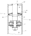
도 1은 감쇠 밸브 장치의 영역의 진동 감쇠기의 일부를 도시한 도면이다.
도 2는 밸브 디스크들을 구비한 압력 제어 밸브를 도시한 도면이다.
도 3 및 도 4는 스로틀링부의 그루브 내의 압력 제어 밸브를 도시한 도면이다.
도 5는 스로틀링부의 링 요소의 밀봉 립을 구비한 압력 제어 밸브를 도시한 도면이다.
도 6 내지 도 8은 압력 제어 밸브의 구성 요소로서 스로틀링부의 캐리어 디스크를 구비한 압력 제어 밸브를 도시한 도면이다.1 is a view showing a part of a vibration damper in the region of a damping valve device;
Figure 2 shows a pressure control valve with valve disks;
3 and 4 are views illustrating a pressure control valve in a groove of a throttling unit.
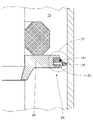
5 shows a pressure control valve with a sealing lip of a ring element of a throttling part;
6 to 8 are views illustrating a pressure control valve having a carrier disk of a throttling unit as a component of the pressure control valve.
도 1은 부분적으로만 도시된 임의 구조의 진동 감쇠기(3)를 위한 감쇠 밸브 장치(1)를 도시한다. 감쇠 밸브 장치(1)는, 피스톤 로드(9)에 고정되는, 피스톤(7)으로서 형성된 감쇠 밸브 몸체를 구비한 제1 감쇠 밸브(5)를 포함한다.1 shows a
감쇠 밸브 몸체(7)는 진동 감쇠기의 실린더(11)를 피스톤 로드 측의 작업 챔버(13) 및 피스톤 로드에서 멀리 떨어진 작업 챔버(15)로 분할하고, 이러한 두 작업 챔버들은 감쇠 매체로 채워져 있다. 감쇠 밸브 몸체(7) 내에는 각각 하나의 관류 방향을 위한 통과 채널들이 상이한 피치 원들 상에 형성된다. 통과 채널들의 구성은 단지 예시적인 것으로 간주되어야 한다. 통과 채널(17; 19)들의 출구 측면은 하나 이상의 밸브 디스크(21; 23)에 의하여 적어도 부분적으로 커버된다.The
추가적으로, 진동 감쇠기는 피스톤 로드(9)의 규정된 상승 이동에서부터 실린더 측의 정지면, 예를 들어 피스톤 로드 안내부(27)에 접하는 인장 정지부(25)를 가질 수 있다.Additionally, the vibration damper may have a
인장 정지부(25)는, 형태 결합식 연결부를 통해 피스톤 로드에 직접 고정되는 캐리어 디스크(29)를 포함한다. 인장 정지부 캐리어 디스크(29)의 상부 측면에는 예를 들어 환형 엘라스토머 요소(31)가 놓여지고, 이러한 환형 엘라스토머 요소는 약간의 반경 방향 초기 응력을 통해 피스톤 로드(9)의 진동 이동 시에도 홀딩된다. 엘라스토머 요소(31)는 정지면 상의 정지점에서부터 추가적인 지지 스프링으로서 작용한다.The
캐리어 디스크(29)는 직경이 변화 가능한 링 요소(35)가 안내되는 원주 방향 그루브(33)를 포함한다. 이러한 링 요소(35)는 반경 방향으로 탄성을 갖고, 감쇠 밸브 장치(1)의 일부로서 스로틀링부(37)를 위한 밸브 몸체를 형성한다. 링 요소(35)는 실린더(11)의 내부 벽부와 함께 스로틀링부를 형성하고, 내부 벽부(39)는 유동 안내면을 나타낸다.The
외부측에서 링 요소는 예를 들어 리테이닝 링 형태의 제한 링(41)을 지지한다. 링 요소의 반경 방향 내부에는, 링 요소(35)의 외부 재킷면(45)을 원주 방향 그루브(33)의 하나의 그루브 바닥과 연결하는 압력 보상 채널(43)들이 형성된다.On the outside the ring element supports a limiting
제1 작동 영역, 예를 들어 1m/s 미만의 피스톤 로드 속도에서, 스로틀링부(37)는 완전히 개방된다. 이 경우, 감쇠력은 밸브 디스크(21; 23)들과 연결된 통과 채널(17; 19)들에 의해서만 생성된다. 밸브 디스크(21; 23)들에 대한 접근 유동 시에, 밸브 디스크(21; 23)들은 자신들의 밸브 시트면(47; 49)으로부터 들어 올려진다. 이러한 리프팅 이동은 각각 지지 디스크(51; 53)에 의해 제한된다.In the first operating region, for example at a piston rod speed of less than 1 m/s, the throttling
제1 작동 영역의 한계 속도보다 더 빠른, 즉 예를 들어 설명된 1m/s보다 더 빠른 피스톤 로드 속도를 갖는 제2 작동 영역에서, 링 요소(35)는 스로틀링 위치로 변경되고, 이 경우 유동 안내면(39)의 방향으로의 폐쇄 이동을 실행한다. 환형 간극으로서 형성된 스로틀링부(37) 내에서의 감쇠 매체의 높은 유속으로 인해, 링 요소(35)의 반경 방향 확장을 야기하는 부압이 형성된다. 그러나, 스로틀링부(37)의 차단이 어떠한 경우에도 발생할 수 없도록, 규정된 최소 통과 횡단면이 제한 링(41)에 의해 유지된다.In the second working region with a piston rod speed higher than the limit speed of the first working region, ie higher than the described 1 m/s for example, the
한편으로, 규정된 최소 횡단면은 스로틀링 효과를 달성하기 위해 비교적 작아야 한다. 다른 한편으로, 예를 들어 링 요소(35)의 외부 직경; 링 요소(35)의 제한을 다시 결정하는 제한 링(41)의 치수; 또는 실린더(11)의 내부 직경;도 제조 공차가 발생한다. 관련된 구성 요소의 모든 공차들이 바람직하지 않은 조합으로 발생하는 경우, 스로틀링부(37) 내의 스로틀링 효과가 너무 클 수 있을 것이고, 경우에 따라서는 진동 감쇠기 또는 부품들에 유해한 영향을 미칠 수 있을 것이다. 이러한 위험을 최소화하기 위하여, 스로틀링부에는 압력 제어 밸브(55; 57)가 유압식으로 병렬 접속된다. 이러한 도면에서, 압력 제어 밸브(55; 57)는 대체 표식으로서 기입되어 있다. 스로틀링부(37)가 실린더(11)로부터의 피스톤 로드 하강 이동 시에서 뿐만 아니라 피스톤 로드 상승 이동 시에도 관류되기 때문에, 스로틀링부(37)의 2개의 관류 방향들을 위해 압력 제어 밸브(55; 57)가 존재한다는 것이 쉽게 확인 가능할 것이다.On the one hand, the specified minimum cross-section must be relatively small in order to achieve the throttling effect. On the other hand, for example, the outer diameter of the
도 2a에는, 압력 제어 밸브(55)가, 하나 이상의 탄성 밸브 디스크(61)에 의해 커버된 유출 횡단면(59)을 포함하는 것이 예시적으로 도시되어 있다. 이러한 구조 형상도 2개의 관류 방향들을 위해 구성될 수 있다. 밸브 디스크의 수, 직경 및 두께에 따라 압력 제어 밸브(55)의 개방 거동이 형성될 수 있다.2A , it is exemplarily shown that the
도 2b는 감쇠 밸브 장치(1)의 힘-속도 다이어그램을 단순화하여 도시한다. 속도(v0)에서 시작하여, 감쇠 밸브(5)는 속도(v1)에 이르기까지의 실선에 상응하는 점진적인 특성 곡선을 갖는다. 그 이후, 스로틀링부(37)의 작용이 파선 특성 곡선에 상응하게 사용된다. 속도(V2)에서부터 압력 제어 밸브(55; 57)는 개방된다. 압력 제어 밸브(55; 57)가 오리피스판으로서 형성되는 경우, 감쇠력은 V2에서부터의 수평 특성 곡선에 의해 도시되는 바와 같이 속도 증가 시에도 일정하게 유지된다.2b shows a simplified force-velocity diagram of the damping
그러나, 도 2a에 따른 밸브 디스크(61)가 사용되는 경우, 특성 곡선은 쇄선의 특성 곡선 섹션들이 도시하는 바와 같이 속도(V2) 너머에서 더욱 가변적으로 형성될 수 있다.However, if the
도 3은 스로틀링부(37)의 링 요소(35)를 위한 그루브(33)가 압력 제어 밸브의 구성 요소를 형성하는 변형예의 압력 제어 밸브(55)를 구비한 감쇠 밸브 장치의 일부를 도시한다. 그루브(33)는 유입 채널(63) 및 유출 채널(65)에 연결된다. 그루브(33)와 연결된 2개의 채널(63; 65)들을 통해, 작업 챔버 섹션들은 피스톤 로드 측의 작업 챔버(13)의 캐리어 디스크(29)의 2개의 측면들을 향해 서로 연결될 것이다. 그러나, 이러한 2개의 채널(63; 65)들의 개방형 연결부는 링 요소(35)에 의해 적어도 확실히 스로틀링되므로, 링 요소는 압력 제어 밸브(55)의 구성 요소를 형성한다.3 shows a part of a damping valve arrangement with a
예를 들어, 링 요소(35)는 상이한 스프링 비를 갖는 2개 이상의 체적 영역(67; 69)들을 포함하고, 이러한 체적 영역들은 서로 동심으로 배열되고, 서로 직접 연결된다. 링 요소(35)는 예를 들어 사출 성형 기술에 의해 2개 구성 요소 공정으로 제조될 수 있다. V2까지의 속도 영역에서, 반경 방향 내부 체적 성분(67)은 그루브(33)의 그루브 측면(71)에서 시작하는 유출 채널(65)을 폐쇄한다. 유입 채널(63)은 그루브(33)의 그루브 바닥면(73)으로 이어진다. V2에서부터 시작되는 내부 체적 성분(67)의 더 높은 압축 시에, 유출 채널(65)은 내부 체적 성분(67)으로부터 자유로워진다. 이를 통해, 더 부드러운 체적 영역(67)은 압력 제어 밸브(55)의 밸브 요소를 형성한다. 링 요소(35)의 외부 체적 성분(69)은 제한 링(41)을 통해 지지된다. 이에 따라, 외부 체적 성분(69)은 반경 방향 외부를 향해 더 변위될 수 없다.For example, the
유입 채널(63)로부터의 압력 레벨이 다시 감소하는 경우, 탄성 체적 성분(67)은 다시 그루브 바닥면(73) 상의 자신의 초기 위치를 취할 수 있으며, 유출 채널(65)과 이에 따라 압력 제어 밸브(55)도 폐쇄할 수 있다.When the pressure level from the
도 4에 따른 스로틀링부(37)의 구성에서는 예를 들어 2개의 유입 채널(63)들과 2개의 유출 채널(65)들이 도시되어 있다. 링 요소(35)의 반경 방향 확장에 따라, 더 많거나 더 적은 유입- 및 유출 채널(63; 65)들이 작용하거나 링 요소(35)에 의해 활성화된다. 유입 채널(63)들 대 유출 채널(65)들의 유효 횡단면 비를 통해, 그루브(33) 내부의 압력 레벨이 결정될 수 있다. 다시 이러한 압력 레벨은 링 요소의 반경 방향 확장에 대해 그리고 이에 따라 스로틀링부(37)의 횡단면에 대해 결정적이다. 예를 들어, 유입 채널(63)들이 상이한 피치 원들 상에 배열되고, 유입 채널(63)들의 횡단면은 더 작은 피치 원 직경 상에서보다, 더 큰 피치 원 직경 상에서 더 작은 것이 제공된다. 다른 한편으로, 유출 채널(65)들의 횡단면들은 피치 원 직경이 증가함에 따라 증가할 수 있다. 이로 인해, 조정 효과가 달성된다. 제한 링은 그루브(33)의 방향으로의 링 요소(35)의 복원 이동을 제공한다. 결과적으로, 유입 채널(63)들, 유출 채널(65)들, 그루브(33), 링 요소(35) 및 제한 링(41)은 압력 제어 밸브(57)를 형성한다.In the configuration of the throttling
압력 제어 밸브(55; 57)의 부분으로서의 스로틀링부(37)의 링 요소(35)를 사용하는 또 다른 가능성은, 링 요소(35)가, 압력 제어 밸브(55; 57)의 밸브 몸체를 형성하는 탄성 립(75)을 포함하는 것이다. 도 5에는 이러한 원리가 구현된다. 이러한 발상은, 축방향 압력 하중이 너무 클 때 탄성 립(75)이 변형되고, 이에 따라 스로틀링 횡단면이 확대되는 것이다. 제한 링(41)은 밀봉 립(75)의 반경 방향 외부에 배열되지만, 밀봉 립(75)을 위한 틸팅 에지를 형성할 수 있다.Another possibility of using the
스로틀링부(37)의 구조 공간으로부터 떨어져 있는 감쇠 밸브 장치의 구조 공간 영역 내에 압력 제어 밸브(55; 57)가 배열되는, 즉 링 요소(35) 또는 그루브(33)가 압력 제어 밸브(55; 57)와 관련되지 않는 도 2의 실시예에 추가하여, 도 6은 이러한 기준에 따른 추가 구성 가능성을 도시한다. 이 경우, 캐리어 디스크(29)는 압력 제어 기능을 위한 필수 구성 요소이다.A
도 6에서, 링 요소(35)는 캐리어 디스크 내에 배열되고, 이를 통해 압력 제어 밸브(55; 57)의 유출 횡단면이 결정된다. 캐리어 디스크(29)는, 피스톤 로드(9)와 형태 결합식으로 연결된 중앙 캐리어 슬리브(77)를 포함한다. 반경 방향 외측으로, 캐리어 슬리브(77)는 디스크 몸체(79)와 견고하게 연결되고, 이러한 디스크 몸체는 예를 들어 플라스틱으로 구성됨으로써 경계부들 내에서 축방향으로 탄성 변형 가능하다. V2 위에서 발생하는 상응하는 높이의 압력 인가 시에, 디스크 몸체(79)는 자체적으로 차폐되고, 이와 같이 자신의 외부 직경을 감소시킨다. 결과적으로, 실린더(11)의 내부 벽부(39)와 링 요소(35) 사이의 스로틀링 간극도 확대된다. 이로 인해, 스로틀링부(37)는 자체적으로 조정되고, 즉 스로틀링부(37)는 압력 제어 밸브(55; 57)를 즉시 형성한다.In FIG. 6 , a
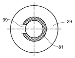
도 7에 따른 실시예에서, 캐리어 디스크(29)는, 바람직하게는 금속 디스크에 의해 형성된 강성의 기본 몸체를 갖는다. 캐리어 디스크(29)는, 캐리어 디스크(29)가 틸팅 이동을 실행하도록 하는 변형 가능한 체적 영역(81; 83)을 포함한다. 이를 위해, 변형 가능한 체적 영역(81; 83)은 예를 들어 c자형 엘라스토머 몸체로서 형성되고, 이러한 엘라스토머 몸체는 캐리어 디스크(29)의 커버 측면(89; 91)의 상응하는 그루브(85; 87) 내에 자신의 챔버를 갖는다. 피스톤 로드의 종축(93)에 대해 점대칭으로, 대향 배치된 커버 측면(91)에서는 변형 가능한 c자형 제2 엘라스토머 몸체(83)가 자신의 챔버를 갖는다. 예를 들어, 2개의 리테이닝 링(95; 97)들이 캐리어 디스크(29)의 축방향 지지를 담당한다. 리테이닝 링(95; 97)들의 외부 직경은 엘라스토머 몸체(81; 83)들의 각각의 외부 직경보다 더 작다. 결과적으로, 캐리어 디스크(29)는 틸팅 이동을 실행할 수 있다. 엘라스토머 몸체(81; 83)들의 단부들 사이의 남아있는 잔여 웹(99)으로 인하여, 캐리어 디스크(29)의 축방향 이동이 방지된다. 각각의 리테이닝 링(95; 97)과 연결된 잔여 웹(99)은 캐리어 디스크(29)의 틸팅점을 결정한다.In the embodiment according to FIG. 7 , the
도 8에 따른 실시예에 의해서는, 캐리어 디스크(29)가 축방향으로 이동 가능하게 장착될 수 있고, 이를 통해 조절 이동이 압력 제어 밸브(55; 57)의 밸브 몸체로서 실행되는 것이 도시될 것이다. 이를 위해, 피스톤 로드(9)는 예를 들어 2개의 대향 배치된 밸브 시트면(103; 105)들을 포함하는 환형 직경 확대부(101)를 갖는다. 제조 공차의 범주 내에서, 직경 확대부(101)의 축방향 길이는 캐리어 디스크(29)의 재료 두께에 상응한다. 밸브 시트면(103; 105)들의 양측에는, 밸브 시트면(103; 105) 및 캐리어 디스크(29)의 할당된 커버 측면(89; 91)과 반경 방향으로 중첩된 밸브 디스크(107; 109)가 배열된다. 반경 방향으로, 밸브 디스크들은 피스톤 로드(9) 상의 반경 방향 웹들을 통해 중심 설정된다. 밸브 디스크(103; 105) 상에는 각각 하나의 커버 디스크(111; 113)가 놓여지고, 이러한 커버 디스크는 반경 방향 내부를 향한 웹들을 마찬가지로 포함하고, 이러한 웹들의 간극들은 유동 횡단면(115; 117)을 형성한다. 커버 디스크(111; 113) 상에는, 스프링 요소(119; 121), 바람직하게는 접시 스프링 또는 주름형 스프링이 배열된다. 내부 링으로부터 시작하여 반경 방향 외부를 향하는 웹들을 포함하는 커버 디스크(123; 125)가 이에 후속된다. 이러한 커버 디스크(123; 125)는 리테이닝 링(127; 129)에 축방향으로 지지된다. 전체적으로, 커버 디스크들은 규정된 유동 횡단면을 형성하기 위해 사용된다. 이러한 기능은 스프링 요소(119; 121)의 형상을 통해서도 구현될 수 있다.It will be shown by the embodiment according to FIG. 8 that the
캐리어 디스크(29)에 대한 접근 유동이 V2 미만일 때, 캐리어 디스크(29)는 피스톤 로드(9)에 대한 그리고 이에 따라 밸브 시트면(103; 105)들에 대한 도시된 축방향 위치를 유지한다. 이러한 접근 유동이 속도(V2)를 초과하는 경우, 캐리어 디스크(29)는 예를 들어 밸브 디스크(107)와 함께 스프링 요소(119)의 힘에 대항하여 이동된다. 이 경우, 밸브 디스크(107)는 밸브 시트면(103)으로부터 들어 올려진다. 대향 배치된 밸브 시트면(105) 상의 밸브 디스크(109)는 자신의 현재 위치를 유지한다. 이를 통해, 캐리어 디스크의 커버 측면(91)과 밸브 디스크(109) 사이에 환형 간극이 생성된다. 캐리어 디스크(29)의 안내부(127)와 직경 확대부(101) 사이에는 축방향 채널(129)이 존재하므로, 캐리어 디스크(29) 양측의 작업 챔버 영역들 사이의 연결부가 개방된다.When the approach flow to the
접근 유동이 V2보다 낮은 레벨로 되돌아오면, 더욱 강한 초기 응력이 가해지는 스프링 요소(119)는 캐리어 디스크(29)와, 밸브 시트면(103)으로부터 들어 올려지는 밸브 디스크(107)를 도시된 초기 위치로 다시 가압한다.When the approach flow returns to a level lower than V 2 , the
커버 측면(89)에 대한 접근 유동 시에, 밸브 디스크(109)는 밸브 시트면(105)으로부터 들어 올려지는 동시에, 밸브 시트면(103)에 홀딩되는 밸브 디스크(107)와 커버 측면(89) 사이의 환형 간극을 형성한다. 이에 따라, 압력 제어 밸브(55; 57)들은 캐리어 디스크의 2개의 접근 유동 방향들을 위해 구현된다.Upon flow approaching the
1
감쇠 밸브 장치
67
체적 영역
3
진동 감쇠기
69
체적 영역
5
제1 감쇠 밸브
71
그루브 측면
7
감쇠 밸브 몸체
73
그루브 바닥면
9
피스톤 로드
75
립
11
실린더
77
캐리어 슬리브
13
피스톤 로드 측의 작업 챔버
79
디스크 몸체
15
피스톤 로드에서 멀리 떨어진 작업 챔버
81
체적 영역
17
통과 채널
83
체적 영역
19
통과 채널
85
그루브
21
밸브 디스크
87
그루브
23
밸브 디스크
89
커버 측면
25
인장 정지부
91
커버 측면
27
피스톤 로드 안내부
93
종축
29
캐리어 디스크
95
리테이닝 링
31
엘라스토머 요소
97
리테이닝 링
33
그루브
99
잔여 웹
35
링 요소
101
직경 확대부
37
스로틀링부
103
밸브 시트면
39
내부 벽부
105
밸브 시트면
41
제한 링
107
밸브 디스크
43
압력 보상 채널
109
밸브 디스크
45
재킷면
111
커버 디스크
47
밸브 시트면
113
커버 디스크
49
밸브 시트면
115
유동 횡단면
51
지지 디스크
117
유동 횡단면
53
지지 디스크
119
스프링 요소
55
압력 제어 밸브
121
스프링 요소
57
압력 제어 밸브
123
커버 디스크
59
유출 횡단면
125
커버 디스크
61
밸브 디스크
127
안내부
63
유입 채널
129
축방향 채널
65
유출 채널1 Damping
3
5
7 Damping
9
11
13 Working chamber on
15
17
19
21
23
25
27
29
31
33
35
37
39
41
43
45
47
49
51
53
55
57
59
61
63
65 Outflow Channels
Claims (11)
스로틀링부(39)에는 압력 제어 밸브(55; 57)가 유압식으로 병렬 접속되는 것을 특징으로 하는, 감쇠 밸브 장치.A damping valve arrangement (1) for a vibration damper (3) with a piston rod (9) comprising a first damping valve (5) which is changed into a through-acting position in a first operating region in which the flow rate of the damping medium is increased. , a second operating region with a gradual damping force characteristic curve from the passing position to the throttling position according to the flow rate in the throttle position 37 , irrespective of the lifting position of the piston rod 9 in the vibration damper 3 . Affected by a throttling portion 37 connected with a changeable valve body 35 , the valve body 35 moves to a closed position as the flow rate of the damping medium increases, hydraulically in series with respect to the damping valve 5 . A damping valve arrangement, wherein the valve body (35) is formed as a variable-diameter ring element, which is arranged as a ,
A damping valve arrangement, characterized in that the throttling part (39) is connected in parallel hydraulically with a pressure control valve (55; 57).
Applications Claiming Priority (3)
| Application Number | Priority Date | Filing Date | Title |
|---|---|---|---|
| DE102019212966.8A DE102019212966A1 (en) | 2019-08-29 | 2019-08-29 | Damping valve device with progressive damping force characteristic |
| DE102019212966.8 | 2019-08-29 | ||
| PCT/EP2020/073632 WO2021037798A1 (en) | 2019-08-29 | 2020-08-24 | Damping valve device having a progressive damping force characteristic curve |
Publications (1)
| Publication Number | Publication Date |
|---|---|
| KR20220050902A true KR20220050902A (en) | 2022-04-25 |
Family
ID=72234862
Family Applications (1)
| Application Number | Title | Priority Date | Filing Date |
|---|---|---|---|
| KR1020227006255A KR20220050902A (en) | 2019-08-29 | 2020-08-24 | Damping valve device with gradual damping force characteristic curve |
Country Status (5)
| Country | Link |
|---|---|
| US (1) | US20220403910A1 (en) |
| KR (1) | KR20220050902A (en) |
| CN (1) | CN114341522A (en) |
| DE (1) | DE102019212966A1 (en) |
| WO (1) | WO2021037798A1 (en) |
Families Citing this family (18)
| Publication number | Priority date | Publication date | Assignee | Title |
|---|---|---|---|---|
| DE102020209108A1 (en) | 2020-07-21 | 2022-01-27 | Zf Friedrichshafen Ag | throttle point |
| DE102021201436B4 (en) | 2021-02-16 | 2024-01-11 | Zf Friedrichshafen Ag | Damping valve device with progressive damping force characteristic |
| DE102021201438B3 (en) | 2021-02-16 | 2022-05-12 | Zf Friedrichshafen Ag | Damping valve device with progressive damping force characteristic |
| DE102021201440A1 (en) | 2021-02-16 | 2022-08-18 | Zf Friedrichshafen Ag | Damping valve device with progressive damping force characteristic |
| DE102021201430A1 (en) | 2021-02-16 | 2022-08-18 | Zf Friedrichshafen Ag | Damping valve device for a vibration damper |
| DE102021201421B4 (en) | 2021-02-16 | 2023-02-02 | Zf Friedrichshafen Ag | Damping valve device for a vibration damper |
| DE102021201426B3 (en) | 2021-02-16 | 2022-05-25 | Zf Friedrichshafen Ag | Damping valve device with progressive damping force characteristic |
| DE102021201441A1 (en) | 2021-02-16 | 2022-08-18 | Zf Friedrichshafen Ag | Damping valve device with progressive damping force characteristic |
| DE102021201425A1 (en) | 2021-02-16 | 2022-08-18 | Zf Friedrichshafen Ag | Damping valve device with progressive damping force characteristic |
| DE102021213455B4 (en) | 2021-11-30 | 2023-07-20 | Zf Friedrichshafen Ag | damping valve device |
| DE102021213457B4 (en) | 2021-11-30 | 2023-07-20 | Zf Friedrichshafen Ag | damping valve device |
| DE102022200699B4 (en) | 2022-01-21 | 2023-09-28 | Zf Friedrichshafen Ag | Damping valve device with progressive damping force characteristic |
| DE102022204982A1 (en) | 2022-05-19 | 2023-11-23 | Zf Friedrichshafen Ag | Damping valve device for a vibration damper |
| DE102022204988A1 (en) | 2022-05-19 | 2023-11-23 | Zf Friedrichshafen Ag | Damping valve device with progressive damping force characteristic |
| DE102022204984A1 (en) | 2022-05-19 | 2023-11-23 | Zf Friedrichshafen Ag | Method for adjusting a damping valve device |
| DE102022204997A1 (en) | 2022-05-19 | 2023-11-23 | Zf Friedrichshafen Ag | Damping valve device with an overload valve |
| DE102022204993A1 (en) | 2022-05-19 | 2023-11-23 | Zf Friedrichshafen Ag | Damping valve device for a vibration damper |
| DE102022204980A1 (en) | 2022-05-19 | 2023-11-23 | Zf Friedrichshafen Ag | Damping valve device with a progressive damping force characteristic |
Family Cites Families (11)
| Publication number | Priority date | Publication date | Assignee | Title |
|---|---|---|---|---|
| DE10318018B4 (en) * | 2002-05-24 | 2015-06-11 | Zf Friedrichshafen Ag | Kolbendämpfventil |
| ES2246138B1 (en) * | 2004-04-28 | 2007-03-16 | Kyb Suspensions Europe, S.A. | HYDRAULIC REBOOT BUMPER FOR HYDRAULIC SHOCK ABSORBERS. |
| DE102004054474B3 (en) * | 2004-11-11 | 2006-06-08 | Zf Friedrichshafen Ag | Vibration damper with adjustable damping force |
| DE102005046276B3 (en) * | 2005-09-27 | 2007-06-14 | Thyssenkrupp Bilstein Suspension Gmbh | Damping valve device with progressive Dämpfkraftverlauf |
| DE102012212684B3 (en) * | 2012-07-19 | 2013-11-28 | Zf Friedrichshafen Ag | Vibration damper, has auxiliary piston and main piston fitted with damping valves, where damping force generated by auxiliary piston through its entire stroke is always greater than damping force of main piston at same stroke speed |
| DE102014203598A1 (en) * | 2014-02-27 | 2015-08-27 | Zf Friedrichshafen Ag | Vibration damper with an end stop |
| DE102016210790A1 (en) * | 2016-06-16 | 2017-12-21 | Zf Friedrichshafen Ag | Damping valve device with progressive damping force characteristic |
| JP6731537B2 (en) * | 2017-02-22 | 2020-07-29 | Kyb株式会社 | Shock absorber |
| DE102017204923A1 (en) * | 2017-03-23 | 2018-09-27 | Zf Friedrichshafen Ag | Slotted sealing ring, in particular for a vibration damper |
| DE102017211300B3 (en) * | 2017-07-04 | 2018-10-04 | Zf Friedrichshafen Ag | Vibration damper for a motor vehicle |
| WO2019048179A1 (en) * | 2017-09-06 | 2019-03-14 | Zf Friedrichshafen Ag | Piston-cylinder unit |
-
2019
- 2019-08-29 DE DE102019212966.8A patent/DE102019212966A1/en active Pending
-
2020
- 2020-08-24 KR KR1020227006255A patent/KR20220050902A/en unknown
- 2020-08-24 CN CN202080060060.6A patent/CN114341522A/en active Pending
- 2020-08-24 US US17/638,438 patent/US20220403910A1/en active Pending
- 2020-08-24 WO PCT/EP2020/073632 patent/WO2021037798A1/en active Application Filing
Also Published As
| Publication number | Publication date |
|---|---|
| US20220403910A1 (en) | 2022-12-22 |
| CN114341522A (en) | 2022-04-12 |
| WO2021037798A1 (en) | 2021-03-04 |
| DE102019212966A1 (en) | 2021-03-04 |
Similar Documents
| Publication | Publication Date | Title |
|---|---|---|
| KR20220050902A (en) | Damping valve device with gradual damping force characteristic curve | |
| KR102374626B1 (en) | Damping valve device with a damping force characteristic curve | |
| US8132654B2 (en) | Hydraulic damper with compensation chamber | |
| EP1600662B1 (en) | Hydraulic shock absorber | |
| US8066105B2 (en) | Hydraulic suspension damper | |
| US11300174B2 (en) | Damping valve device for a vibration damper | |
| EP2233775B1 (en) | Hydraulic suspension damper | |
| JP5183096B2 (en) | Shock absorber check valve | |
| KR20090093813A (en) | Damper | |
| KR20080045759A (en) | Shock absorber | |
| CN112483579B (en) | Hydraulic damper with pull stop and push stop | |
| US6179100B1 (en) | Blockable piston-cylinder unit | |
| CN117083472A (en) | Damping valve device with progressive damping force characteristic line | |
| CN113958643A (en) | Limiting body of vibration damper | |
| CN113958644A (en) | Damping valve device with increasing damping force characteristic curve | |
| CN108700154B (en) | Bi-directional soft open valve arrangement for shock absorber | |
| US7111711B2 (en) | Vibration damper with stroke-dependent damping force | |
| US6202979B1 (en) | Valve | |
| CN109154351B (en) | Damping valve, in particular for a vibration damper | |
| US20220128114A1 (en) | Hydraulic damper assembly and a piston for a hydraulic damper assembly | |
| US7182190B2 (en) | Vibration damper with fire safety device | |
| CN116888379A (en) | Damping valve device with progressive damping force characteristic curve | |
| CN114941678A (en) | Damper valve device for a damper | |
| CN113958645A (en) | Damping valve device for vibration damper | |
| CN114941677A (en) | Damping valve device for shock absorber |