KR20220005431A - Systems and methods for imaging and detecting vibrations - Google Patents
Systems and methods for imaging and detecting vibrations Download PDFInfo
- Publication number
- KR20220005431A KR20220005431A KR1020217027417A KR20217027417A KR20220005431A KR 20220005431 A KR20220005431 A KR 20220005431A KR 1020217027417 A KR1020217027417 A KR 1020217027417A KR 20217027417 A KR20217027417 A KR 20217027417A KR 20220005431 A KR20220005431 A KR 20220005431A
- Authority
- KR
- South Korea
- Prior art keywords
- processor
- illumination
- sensor
- pixels
- output signal
- Prior art date
Links
- 238000000034 method Methods 0.000 title claims abstract description 91
- 238000003384 imaging method Methods 0.000 title abstract description 7
- 238000005286 illumination Methods 0.000 claims abstract description 82
- 230000008859 change Effects 0.000 claims description 61
- 230000007423 decrease Effects 0.000 claims description 14
- 238000012795 verification Methods 0.000 claims description 8
- 230000003247 decreasing effect Effects 0.000 claims description 6
- 238000005259 measurement Methods 0.000 description 34
- 238000010586 diagram Methods 0.000 description 22
- 230000002123 temporal effect Effects 0.000 description 16
- 238000004891 communication Methods 0.000 description 11
- 238000001514 detection method Methods 0.000 description 9
- 230000005540 biological transmission Effects 0.000 description 8
- 238000004364 calculation method Methods 0.000 description 8
- 238000012545 processing Methods 0.000 description 8
- 238000010200 validation analysis Methods 0.000 description 8
- 230000008901 benefit Effects 0.000 description 5
- 230000005670 electromagnetic radiation Effects 0.000 description 5
- 238000012986 modification Methods 0.000 description 5
- 230000004048 modification Effects 0.000 description 5
- 230000004044 response Effects 0.000 description 5
- 238000012544 monitoring process Methods 0.000 description 4
- 239000000835 fiber Substances 0.000 description 3
- 230000006870 function Effects 0.000 description 3
- 230000001788 irregular Effects 0.000 description 3
- 238000013507 mapping Methods 0.000 description 3
- 230000010355 oscillation Effects 0.000 description 3
- 238000005070 sampling Methods 0.000 description 3
- 230000006978 adaptation Effects 0.000 description 2
- 230000008878 coupling Effects 0.000 description 2
- 238000010168 coupling process Methods 0.000 description 2
- 238000005859 coupling reaction Methods 0.000 description 2
- 238000013016 damping Methods 0.000 description 2
- 230000010354 integration Effects 0.000 description 2
- 230000003287 optical effect Effects 0.000 description 2
- 230000009467 reduction Effects 0.000 description 2
- 230000003068 static effect Effects 0.000 description 2
- 230000001360 synchronised effect Effects 0.000 description 2
- 230000001960 triggered effect Effects 0.000 description 2
- 230000002159 abnormal effect Effects 0.000 description 1
- 238000009825 accumulation Methods 0.000 description 1
- 239000003990 capacitor Substances 0.000 description 1
- 230000001427 coherent effect Effects 0.000 description 1
- 238000010276 construction Methods 0.000 description 1
- 238000012217 deletion Methods 0.000 description 1
- 230000037430 deletion Effects 0.000 description 1
- 230000001747 exhibiting effect Effects 0.000 description 1
- 238000001914 filtration Methods 0.000 description 1
- 230000006872 improvement Effects 0.000 description 1
- 238000003780 insertion Methods 0.000 description 1
- 230000037431 insertion Effects 0.000 description 1
- 238000010606 normalization Methods 0.000 description 1
- 239000013307 optical fiber Substances 0.000 description 1
- 230000002093 peripheral effect Effects 0.000 description 1
- 238000012805 post-processing Methods 0.000 description 1
- 230000005855 radiation Effects 0.000 description 1
- 230000008707 rearrangement Effects 0.000 description 1
- 230000035945 sensitivity Effects 0.000 description 1
Images


Classifications
-
- G—PHYSICS
- G01—MEASURING; TESTING
- G01H—MEASUREMENT OF MECHANICAL VIBRATIONS OR ULTRASONIC, SONIC OR INFRASONIC WAVES
- G01H9/00—Measuring mechanical vibrations or ultrasonic, sonic or infrasonic waves by using radiation-sensitive means, e.g. optical means
-
- G—PHYSICS
- G01—MEASURING; TESTING
- G01H—MEASUREMENT OF MECHANICAL VIBRATIONS OR ULTRASONIC, SONIC OR INFRASONIC WAVES
- G01H9/00—Measuring mechanical vibrations or ultrasonic, sonic or infrasonic waves by using radiation-sensitive means, e.g. optical means
- G01H9/002—Measuring mechanical vibrations or ultrasonic, sonic or infrasonic waves by using radiation-sensitive means, e.g. optical means for representing acoustic field distribution
-
- G—PHYSICS
- G01—MEASURING; TESTING
- G01D—MEASURING NOT SPECIALLY ADAPTED FOR A SPECIFIC VARIABLE; ARRANGEMENTS FOR MEASURING TWO OR MORE VARIABLES NOT COVERED IN A SINGLE OTHER SUBCLASS; TARIFF METERING APPARATUS; MEASURING OR TESTING NOT OTHERWISE PROVIDED FOR
- G01D5/00—Mechanical means for transferring the output of a sensing member; Means for converting the output of a sensing member to another variable where the form or nature of the sensing member does not constrain the means for converting; Transducers not specially adapted for a specific variable
- G01D5/26—Mechanical means for transferring the output of a sensing member; Means for converting the output of a sensing member to another variable where the form or nature of the sensing member does not constrain the means for converting; Transducers not specially adapted for a specific variable characterised by optical transfer means, i.e. using infrared, visible, or ultraviolet light
Abstract
본 개시내용은 일반적으로 물체의 진동을 이미징하고 감지하기 위한 시스템 및 방법에 관한 것이다. 하나의 구현예에서, 복수의 픽셀을 가진 센서를 포함하는 시스템이 진동을 검출하기 위해 제공되고, 각각의 픽셀은 적어도 하나의 감광성 구성요소를 포함한다. 센서는 각각의 픽셀의 조명과 관련된 신호를 출력하도록 구성된다. 시스템은 또한 센서로부터 출력 신호를 수신하고 출력 신호에 기초하여, 하나 이상의 극성을 검출하도록 구성된 적어도 하나의 프로세서를 포함한다. 적어도 하나의 프로세서는 또한 출력 신호와 연관된 타임스탬프를 결정하고, 타임스탬프 및 극성을 분석하여 센서의 시야 내 물체의 진동을 검출하고, 검출된 진동의 하나 이상의 주파수를 결정하도록 구성된다.The present disclosure relates generally to systems and methods for imaging and sensing vibrations of objects. In one implementation, a system comprising a sensor having a plurality of pixels is provided for detecting vibration, each pixel comprising at least one photosensitive component. The sensor is configured to output a signal related to the illumination of each pixel. The system also includes at least one processor configured to receive an output signal from the sensor and detect one or more polarities based on the output signal. The at least one processor is also configured to determine a timestamp associated with the output signal, analyze the timestamp and polarity to detect a vibration of an object within a field of view of the sensor, and determine one or more frequencies of the detected vibration.
Description
본 개시내용은 일반적으로 물체의 이미징 및 감지 특성의 분야에 관한 것이다. 더 구체적으로 그리고 제한 없이, 본 개시내용은 물체의 진동을 검출하고 분석하기 위한 컴퓨터 구현 이미징 시스템 및 방법에 관한 것이다. 본 개시내용은 부가적으로 진동 검출 및 분석을 위한 픽셀 기반 센서를 구현하고 사용하는 것에 관한 것이다. 본 명세서에 개시된 센서 및 기법은 회전 터빈 또는 샤프트와 같은, 움직이는 기계적 구성요소의 분석과 같은, 다양한 적용 및 시스템, 엔진 또는 차량의 상태를 모니터링하기 위한 시스템, 및 정확하고 효율적인 진동 분석으로부터 이익을 얻는 다른 적용 및 시스템에서 사용될 수도 있다.The present disclosure relates generally to the field of imaging and sensing properties of objects. More specifically and without limitation, the present disclosure relates to computer-implemented imaging systems and methods for detecting and analyzing vibrations of objects. The present disclosure additionally relates to implementing and using a pixel-based sensor for vibration detection and analysis. The sensors and techniques disclosed herein benefit from a variety of applications and systems, such as the analysis of moving mechanical components, such as rotating turbines or shafts, systems for monitoring the condition of engines or vehicles, and accurate and efficient vibration analysis. It may be used in other applications and systems.
현존하는 진동 센서, 예컨대, 가속도계는 진동이 측정되는 디바이스 또는 구성요소와 직접적으로 접촉한다. 이러한 센서는 이 장치의 기계적 특성을 변경하므로 정확도가 부족하다. 진동 부품 또는 구성요소가 뜨겁거나 접근할 수 없거나 너무 작아서 접촉 센서의 적용이 불가능한 경우에 측정을 수행할 수 없는 것과 같은 다른 단점도 있다.Existing vibration sensors, such as accelerometers, are in direct contact with the device or component whose vibration is being measured. These sensors alter the mechanical properties of the device and therefore lack accuracy. There are other disadvantages, such as not being able to perform measurements when the vibrating part or component is hot, inaccessible, or too small for the application of a contact sensor.
일부 적용에서, 비간섭성 광(예컨대, 발광 다이오드(light emitted diode: LED)) 및 광검출기를 가진 광섬유는 비접촉 진동 검출기를 제공하기 위해 사용될 수도 있다. 그러나, 이러한 구현은 공간에 걸친 진동을 해결할 수 없다. 게다가, 정확도는 일반적으로 비간섭성 광의 조명의 변화에 대한 광검출기의 감도로 제한된다. In some applications, optical fibers with incoherent light (eg, light emitted diodes (LEDs)) and photodetectors may be used to provide a non-contact vibration detector. However, this implementation cannot address oscillations over space. Furthermore, accuracy is generally limited by the sensitivity of the photodetector to changes in illumination of incoherent light.
충분한 정확도 없이, 진동 패턴(예를 들어, 주파수, 진폭 등)의 느린 변화가 검출되지 않을 수도 있기 때문에 기계 구성요소 및 기계의 느린 감쇠를 검출하는 것은 어렵다. 게다가, 공간적 해상도 없이, 기계의 상이한 부분이 상이한 진동 패턴을 나타내는 경우 다중 부품 기계를 정확하게 모니터링할 수 없다. Without sufficient accuracy, it is difficult to detect slow damping of machine components and machines because slow changes in vibration patterns (eg, frequency, amplitude, etc.) may not be detected. Moreover, without spatial resolution, it is not possible to accurately monitor multi-part machines when different parts of the machine exhibit different vibration patterns.
따라서, 높은 정확도(예를 들어, 높은 시간적 해상도에 기초함)뿐만 아니라 개선된 공간적 해상도를 가진 진동 감지 해결책이 바람직하다.Accordingly, vibration sensing solutions with improved spatial resolution as well as high accuracy (eg, based on high temporal resolution) are desirable.
본 개시내용의 실시형태는 위에서 언급된 단점을 해결하는 컴퓨터 구현 시스템, 방법 및 비일시적인 컴퓨터 저장 매체를 제공한다. 본 개시내용의 실시형태는 높은 시간적 해상도에 의한 진동 검출 및 분석을 위한 실시형태를 포함한다. 또한, 본 개시내용의 실시형태는 공간에 걸쳐 주파수 및 진폭을 구별하는 능력을 가진, 진동 검출 및 분석을 위한 시스템 및 방법을 제공한다. 본 개시내용의 이 특징 및 다른 특징, 양상 및 실시형태는 도 3 내지 도 9를 참조하여 본 명세서에서 상세히 설명된다.Embodiments of the present disclosure provide computer-implemented systems, methods, and non-transitory computer storage media that address the above-mentioned shortcomings. Embodiments of the present disclosure include embodiments for vibration detection and analysis with high temporal resolution. Embodiments of the present disclosure also provide systems and methods for vibration detection and analysis, with the ability to discriminate frequencies and amplitudes across space. This and other features, aspects and embodiments of the present disclosure are described in detail herein with reference to FIGS. 3-9 .
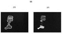
일부 실시형태에서, 생성된 데이터는 복수의 주파수 및 진폭을 포함하여, 장면에서 진동의 2차원 이미지가 예를 들어, 진동 맵으로서 생성되게 할 수도 있다. 이러한 맵의 실시예가 도 9에 예시되고 아래에서 더 설명된다. 부가적으로, 본 개시내용의 실시형태가 기계적 구성요소 및 물체, 예컨대, 공장 기계, 차량 등을 모니터링하기 위해 사용될 수도 있으므로, 컴포넌트의 감쇠가 현존하는 기법보다 더 정확하게 진동 패턴의 변화를 식별함으로써 조기에 검출될 수도 있다.In some embodiments, the generated data may include a plurality of frequencies and amplitudes, such that a two-dimensional image of vibrations in the scene is generated, for example, as a vibration map. An embodiment of such a map is illustrated in FIG. 9 and described further below. Additionally, since embodiments of the present disclosure may be used to monitor mechanical components and objects, such as factory machinery, vehicles, etc., the damping of components can be used to identify changes in vibration patterns more accurately than existing techniques, resulting in early detection of changes in vibration patterns. may be detected in
본 개시내용의 실시형태는 진동을 겪는 물체의 자연광 또는 인공 조명을 사용할 수도 있고/있거나 센서에서 물체의 반사를 생성하기 위해 전자기 펄스(균일하든 또는 구조화되든)를 투사할 수도 있다. 일부 실시형태에서, 센서는 복수의 픽셀을 포함할 수도 있고 반사를 수신하는 픽셀(들)의 위치(들)에 의해 수신된 반사를 인덱싱할 수도 있다. 따라서, 본 개시내용의 실시형태는 픽셀(들)의 공간 좌표에 기초하여 장면의 2차원 투사에 대한 진동 및 진폭을 계산할 수도 있고 매핑할 수도 있다. Embodiments of the present disclosure may use natural or artificial illumination of an object that undergoes vibration and/or may project electromagnetic pulses (whether uniform or structured) to create a reflection of the object at a sensor. In some embodiments, the sensor may include a plurality of pixels and may index the received reflection by the location(s) of the pixel(s) receiving the reflection. Accordingly, embodiments of the present disclosure may calculate and map the vibration and amplitude for a two-dimensional projection of a scene based on the spatial coordinates of the pixel(s).
주파수를 더 정확하게 처리하기 위해, 본 개시내용의 실시형태는 비논리적인 이벤트를 폐기하기 위해 이벤트 카운터를 적용할 수도 있다. 따라서, 진동은 주파수 계산의 정확도를 증가시키기 위해 잡음을 제거하는 동안 검출될 수도 있다. 따라서, 본 개시내용의 실시형태는 위에서 설명된 바와 같이, 현존하는 기법의 일부 단점을 해결할 수도 있다.To more accurately handle frequencies, embodiments of the present disclosure may apply an event counter to discard illogical events. Thus, vibrations may be detected while removing noise to increase the accuracy of the frequency calculation. Accordingly, embodiments of the present disclosure may address some shortcomings of existing techniques, as described above.
일부 실시형태에서, 시간적 해상도는 이벤트 기반 이미지 센서를 사용함으로써 더 증가될 수도 있다. 이러한 센서는 문턱값을 초과하는 특정 픽셀의 조명 변화에 기초하여 장면에서 이벤트를 캡처할 수도 있다. 센서는 비동기식으로 작동할 수 있고 생성되는 데이터의 양을 감소시키면서 장면의 반사로부터 이벤트를 검출할 수 있다. 따라서, 시간적 해상도가 증가될 수도 있다. In some embodiments, temporal resolution may be further increased by using an event-based image sensor. Such sensors may capture events in the scene based on changes in lighting of certain pixels that exceed a threshold. Sensors can operate asynchronously and detect events from reflections of the scene while reducing the amount of data generated. Accordingly, the temporal resolution may be increased.
위에서 설명된 바와 같은 이벤트 기반 이미지 센서의 사용으로 인한 데이터의 감소는 각각의 픽셀에서의 광 샘플링의 속도를 예를 들어, 초당 30회 또는 초당 60회(즉, 일반적인 CMOS 이미지 센서의 프레임 속도)로부터 더 높은 속도, 예컨대, 초당 1,000회, 초당 10,000회 이상으로 증가시키는 것을 허용할 수도 있다. 더 높은 광 샘플링 속도는 현존하는 기법에 비해 주파수 계산의 정확도를 증가시킨다.Reduction of data due to the use of event-based image sensors as described above can increase the rate of light sampling at each pixel, for example, from 30 times per second or 60 times per second (i.e. the frame rate of typical CMOS image sensors). It may allow increments to higher rates, such as 1,000 times per second, 10,000 times per second or more. The higher optical sampling rate increases the accuracy of the frequency calculation compared to existing techniques.
본 개시내용의 실시형태는 또한 현존하는 방식과 달리, 주파수의 공간적 해상도를 제공할 수도 있다. 예를 들어, 이벤트는 전체 이미지 센서에 걸친 조명 또는 다른 특성의 일반적인 변화에 의존하기보다는 개별적인 픽셀에서 검출될 수 있다(그리고 따라서 주파수가 또한 개별적인 픽셀에 대해 계산될 수도 있음). 게다가, 이벤트 기반 센서의 사용은 이러한 공간적 해상도를 더 개선시킨다.Embodiments of the present disclosure may also provide spatial resolution of frequencies, unlike existing schemes. For example, events may be detected at individual pixels (and thus frequencies may also be calculated for individual pixels) rather than relying on general changes in lighting or other characteristics across the entire image sensor. Moreover, the use of event-based sensors further improves this spatial resolution.
본 개시내용의 실시형태는 이미지의 진폭뿐만 아니라 주파수를 검출할 수도 있다. 예를 들어, 본 개시내용의 실시형태는 진폭을 결정하기 위해 검출된 이벤트의 수에 의해 계산된 주파수를 정규화할 수도 있다. 따라서 계산된 진폭의 정확도는 주파수의 정확도가 증가함에 따라 증가할 수도 있다. 게다가, 이벤트가 개별적인 픽셀에서 검출되기 때문에, 진폭은 일반적으로 전체 센서가 아닌 공간에 걸쳐 결정될 수도 있다. 또한, 이벤트 기반 센서를 사용하면 진폭을 더 정확하게 검출할 수도 있다. Embodiments of the present disclosure may detect frequency as well as amplitude of an image. For example, embodiments of the present disclosure may normalize a calculated frequency by a number of detected events to determine amplitude. Therefore, the accuracy of the calculated amplitude may increase as the accuracy of the frequency increases. Furthermore, since events are detected at individual pixels, amplitudes may generally be determined across space rather than the entire sensor. In addition, the use of event-based sensors allows for more accurate detection of amplitude.
본 개시내용의 양상에 따르면, 센서를 포함하는, 진동을 검출하기 위한 시스템이 제공된다. 센서는 복수의 픽셀을 포함하는 센서로서, 각각의 픽셀은 적어도 하나의 감광성 구성요소를 포함할 수도 있다. 센서는 각각의 픽셀의 조명과 관련된 신호를 출력하도록 구성될 수도 있다. 시스템은 센서로부터 출력 신호를 수신하고; 출력 신호에 기초하여, 조명의 하나 이상의 변화를 결정하고, 하나 이상의 변화는 극성 정보를 포함하고, 극성 정보는 조명의 변화가 조명의 증가 또는 감소와 연관되는지를 나타내고; 하나 이상의 변화와 연관된 타임스탬프를 결정하고; 타임스탬프 및 극성 정보를 분석하여 센서의 시야 내 물체의 진동을 검출하고; 그리고 검출된 진동의 하나 이상의 주파수를 결정하도록 구성되는 적어도 하나의 프로세서를 더 포함할 수도 있다.According to an aspect of the present disclosure, there is provided a system for detecting vibration, comprising a sensor. The sensor is a sensor comprising a plurality of pixels, each pixel comprising at least one photosensitive component. The sensor may be configured to output a signal related to the illumination of each pixel. The system receives an output signal from the sensor; determine, based on the output signal, one or more changes in illumination, wherein the one or more changes include polarity information, wherein the polarity information indicates whether the change in illumination is associated with an increase or decrease in illumination; determine a timestamp associated with the one or more changes; analyze the timestamp and polarity information to detect vibrations of objects within the sensor's field of view; and at least one processor configured to determine one or more frequencies of the detected vibrations.
이러한 실시형태에서, 적어도 하나의 프로세서는 조명의 변화가 조명의 증가를 나타낼 때 양의 극성을 결정하고, 조명의 변화가 조명의 감소를 나타낼 때 음의 극성을 결정하도록 구성될 수도 있다.In such an embodiment, the at least one processor may be configured to determine a positive polarity when a change in illumination indicates an increase in illumination, and determine a negative polarity when a change in illumination indicates a decrease in illumination.
이 실시형태 중 임의의 실시형태에서, 조명의 변화는 센서의 복수의 픽셀 중 픽셀의 세트와 연관될 수도 있다. 예를 들어, 하나 이상의 주파수는 조명의 변화에 기초하여 픽셀의 세트와 연관될 수도 있다.In any of these embodiments, the change in illumination may be associated with a set of pixels of a plurality of pixels of the sensor. For example, one or more frequencies may be associated with a set of pixels based on changes in lighting.
이 실시형태 중 임의의 실시형태에서, 적어도 하나의 프로세서는 센서와 연관된 판독 시스템으로부터 복수의 타임스탬프를 추출함으로써 타임스탬프를 결정하도록 구성될 수도 있다. 예를 들어, 판독 시스템은 어드레스 이벤트 표현(address-event representation: AER) 프로토콜에 기초하여 하나 이상의 타임스탬프를 인코딩할 수도 있다. 부가적으로 또는 대안적으로, 판독 시스템은 각각의 출력 신호에 대한 연관된 픽셀을 식별하는 어드레스를 인코딩할 수도 있다.In any of these embodiments, the at least one processor may be configured to determine the timestamps by extracting the plurality of timestamps from a reading system associated with the sensor. For example, the reading system may encode one or more timestamps based on an address-event representation (AER) protocol. Additionally or alternatively, the read system may encode an address identifying an associated pixel for each output signal.
이 실시형태 중 임의의 실시형태에서, 적어도 하나의 프로세서는 복수의 타임스탬프를 사용하여 하나 이상의 극성의 변화 간의 시간 간격을 계산함으로써 타임스탬프를 분석하고, 계산된 시간 간격에 기초하여 하나 이상의 주파수를 결정하도록 구성될 수도 있다. 이러한 실시형태에서, 적어도 하나의 프로세서는 평균값 또는 중앙값, 및 계산된 시간 간격과 연관된 편차를 계산하고; 평균값이 계산될 때 평균값의 역수에 기초하여 하나 이상의 주파수를 결정하거나 또는 중앙값이 계산될 때 중간값에 기초하여 하나 이상의 주파수를 결정하고; 그리고 편차가 검증 문턱값 미만일 때 하나 이상의 주파수를 검증하도록 더 구성될 수도 있다. 예를 들어, 검증 문턱값은 평균값 또는 중앙값의 대략 1% 내지 10%일 수도 있다. 검증 문턱값은, 경우에 따라서, 평균값 또는 중앙값의 1% 이상 내지 10% 이하일 수도 있다.In any of these embodiments, the at least one processor analyzes the timestamps by calculating time intervals between changes in one or more polarities using the plurality of timestamps, and calculates the one or more frequencies based on the calculated time intervals. may be configured to determine. In such an embodiment, the at least one processor calculates a mean or median and a deviation associated with the calculated time interval; determining one or more frequencies based on the reciprocal of the average value when the average value is calculated or determining the one or more frequencies based on the median value when the median value is calculated; and verify the one or more frequencies when the deviation is less than a verification threshold. For example, the validation threshold may be approximately 1% to 10% of the mean or median value. The validation threshold may, in some cases, be greater than or equal to 1% and less than or equal to 10% of the mean or median.
이 실시형태 중 임의의 실시형태에서, 적어도 하나의 프로세서는 진동의 하나 이상의 진폭을 결정하기 위해 복수의 픽셀 중 하나 이상의 픽셀과 연관된 출력 신호를 분석하도록 구성될 수도 있다. 예를 들어, 적어도 하나의 프로세서는 복수의 픽셀로부터 출력 신호에 공간 필터를 적용하고, 적용된 공간 필터에 기초하여, 하나 이상의 진폭을 결정하도록 구성될 수도 있다. 부가적으로 또는 대안적으로, 적어도 하나의 프로세서는 진동을 겪는 물체의 형상을 결정하고, 출력 신호에 대한 2차원 형상 추적을 수행하여 하나 이상의 진폭을 결정하도록 구성될 수도 있다. 예를 들어, 적어도 하나의 프로세서는 반복적인 최근접점 알고리즘을 적용함으로써 2차원 형상 추적을 수행하도록 구성될 수도 있다.In any of these embodiments, the at least one processor may be configured to analyze an output signal associated with one or more pixels of the plurality of pixels to determine one or more amplitudes of vibrations. For example, the at least one processor may be configured to apply a spatial filter to the output signal from the plurality of pixels and to determine, based on the applied spatial filter, one or more amplitudes. Additionally or alternatively, the at least one processor may be configured to determine a shape of an object undergoing vibration and perform two-dimensional shape tracking on the output signal to determine one or more amplitudes. For example, the at least one processor may be configured to perform two-dimensional shape tracking by applying an iterative nearest-neighbor algorithm.
부가적으로 또는 대안적으로, 적어도 하나의 프로세서는 시간 단위 내에서 복수의 픽셀 중 적어도 하나의 픽셀로부터 조명의 변화의 수를 결정하고, 적어도 하나의 픽셀과 연관된 하나 이상의 주파수 중 결정된 주파수에 의해 변화의 수를 정규화하여 하나 이상의 진폭을 결정하도록 구성될 수도 있다. 예를 들어, 시간 단위는 대략 1㎳ 이하일 수도 있다. 시간 단위는 1㎳ 이하일 수도 있다.Additionally or alternatively, the at least one processor determines a number of changes in illumination from at least one pixel of the plurality of pixels within a unit of time, the change by the determined frequency of one or more frequencies associated with the at least one pixel. may be configured to normalize the number of to determine one or more amplitudes. For example, a unit of time may be approximately 1 ms or less. The time unit may be 1 ms or less.
이 실시형태 중 임의의 실시형태에서, 시스템은 센서의 시야 내 물체에 광을 투사하는 외부 광원을 더 포함할 수도 있다. 예를 들어, 외부 광원은 균일한 광 또는 구조광을 투사할 수도 있다. 외부 광원은 일정한 조명을 가진 광을 투사할 수도 있다. 외부 광원은 구조화된 조명 패턴을 포함하는 광을 투사할 수도 있다. 이러한 실시형태에서, 외부 광원은 물체의 적어도 하나의 표면에 대해 비스듬한 각으로 광을 투사할 수도 있다.In any of these embodiments, the system may further include an external light source that projects light to objects within the sensor's field of view. For example, an external light source may project uniform or structured light. An external light source may project light with constant illumination. An external light source may project light comprising a structured illumination pattern. In such embodiments, the external light source may project light at an oblique angle with respect to at least one surface of the object.
이 실시형태 중 임의의 실시형태에서, 적어도 하나의 프로세서는 비논리적인 변화를 제거하기 위해 조명의 하나 이상의 변화를 필터링하도록 구성될 수도 있다.In any of these embodiments, the at least one processor may be configured to filter the one or more changes in illumination to remove illogical changes.
이 실시형태 중 임의의 실시형태에서, 적어도 하나의 프로세서는 시간 문턱값 이상의 차를 가진 타임스탬프를 제거하도록 구성될 수도 있다. 예를 들어, 타임스탬프를 제거하기 위해 사용되는 시간 문턱값은 1㎳ 이상일 수도 있다.In any of these embodiments, the at least one processor may be configured to remove timestamps with differences greater than or equal to a time threshold. For example, the time threshold used to remove the timestamp may be greater than or equal to 1 ms.
일부 실시형태에서, 진동을 검출하기 위한 시스템은 센서를 포함할 수도 있다. 센서는 구성요소 상의 조명 레벨을 검출하도록 구성된 복수의 감광성 구성요소; 감광성 구성요소 중 하나 이상의 감광성 구성요소 상의 검출된 조명 레벨의 변화가 문턱값을 초과할 때 신호를 출력하도록 구성된 복수의 변화 검출기를 포함하는, 센서; 및 적어도 하나의 프로세서를 포함할 수도 있다. 적어도 하나의 프로세서는 출력 신호를 수신하고; 출력 신호에 기초하여, 극성을 결정하고, 극성은 조명이 조명의 증가하는지 또는 감소하는지를 나타내고; 복수의 변화 검출기로부터의 출력 신호와 연관된 타임스탬프를 결정하고; 타임스탬프 및 극성 정보를 분석하여 센서의 시야 내 물체의 진동을 검출하고; 그리고 검출된 진동의 하나 이상의 주파수를 결정하도록 구성될 수도 있다.In some embodiments, a system for detecting vibration may include a sensor. The sensor includes a plurality of photosensitive components configured to detect an illumination level on the component; a sensor comprising a plurality of change detectors configured to output a signal when a detected change in illumination level on one or more of the photosensitive components exceeds a threshold value; and at least one processor. the at least one processor receives the output signal; based on the output signal, determine a polarity, the polarity indicating whether the illumination increases or decreases the illumination; determine a timestamp associated with an output signal from the plurality of change detectors; analyze the timestamp and polarity information to detect vibrations of objects within the sensor's field of view; and determine one or more frequencies of the detected vibrations.
이러한 실시형태에서, 양의 극성은 조명의 증가와 연관되고, 음의 극성은 조명의 감소와 연관된다.In this embodiment, a positive polarity is associated with an increase in illumination and a negative polarity is associated with a decrease in illumination.
이 실시형태 중 임의의 실시형태에서, 극성은 픽셀의 세트와 연관될 수도 있고, 각각의 픽셀은 복수의 감광성 구성요소 중 적어도 하나의 감광성 구성요소를 포함할 수도 있다. 따라서, 하나 이상의 주파수는 극성에 기초하여 픽셀의 세트와 연관될 수도 있다.In any of these embodiments, a polarity may be associated with a set of pixels, and each pixel may include at least one photosensitive component of a plurality of photosensitive components. Accordingly, one or more frequencies may be associated with a set of pixels based on polarity.
이 실시형태 중 임의의 실시형태에서, 적어도 하나의 프로세서는 센서와 연관된 판독 시스템으로부터 복수의 타임스탬프를 추출함으로써 타임스탬프를 결정하도록 구성될 수도 있다. 예를 들어, 판독 시스템은 어드레스 이벤트 표현(AER) 프로토콜에 기초하여 하나 이상의 타임스탬프를 인코딩할 수도 있다. 부가적으로 또는 대안적으로, 판독 시스템은 각각의 출력 신호에 대한 연관된 픽셀을 식별하는 어드레스를 인코딩할 수도 있다.In any of these embodiments, the at least one processor may be configured to determine the timestamps by extracting the plurality of timestamps from a reading system associated with the sensor. For example, the reading system may encode one or more timestamps based on an Address Event Representation (AER) protocol. Additionally or alternatively, the read system may encode an address identifying an associated pixel for each output signal.
이 실시형태 중 임의의 실시형태에서, 적어도 하나의 프로세서는 복수의 타임스탬프를 사용하여 하나 이상의 극성의 변화 간의 시간 간격을 계산하기 위해 타임스탬프를 분석하고, 계산된 시간 간격에 기초하여 하나 이상의 주파수를 결정하도록 구성될 수도 있다. 이러한 실시형태에서, 적어도 하나의 프로세서는 평균값 또는 중앙값, 및 계산된 시간 간격과 연관된 편차를 계산하고, 평균값이 계산될 때 평균값의 역수에 기초하여 하나 이상의 주파수를 결정하거나 또는 중앙값이 계산될 때 중간값의 역수에 기초하여 하나 이상의 주파수를 결정하고, 그리고 편차가 검증 문턱값 미만일 때 하나 이상의 주파수를 검증하도록 더 구성될 수도 있다. 예를 들어, 검증 문턱값은 평균값 또는 중앙값의 대략 1% 내지 10%일 수도 있다. 검증 문턱값은, 경우에 따라서, 평균값 또는 중앙값의 1% 이상 내지 10% 이하일 수도 있다.In any of these embodiments, the at least one processor analyzes the timestamps using the plurality of timestamps to calculate a time interval between the one or more changes in polarity, and based on the calculated time interval, the one or more frequencies may be configured to determine In such embodiments, the at least one processor calculates a mean or median, and a deviation associated with the calculated time interval, and determines one or more frequencies based on the reciprocal of the mean when the mean is calculated or the median when the mean is calculated. and determine the one or more frequencies based on the reciprocal of the values, and verify the one or more frequencies when the deviation is less than a verification threshold. For example, the validation threshold may be approximately 1% to 10% of the mean or median value. The validation threshold may, in some cases, be greater than or equal to 1% and less than or equal to 10% of the mean or median.
이 실시형태 중 임의의 실시형태에서, 적어도 하나의 프로세서는 진동의 하나 이상의 진폭을 결정하기 위해 출력 신호를 분석하도록 구성될 수도 있다. 예를 들어, 적어도 하나의 프로세서는 출력 신호에 공간 필터를 적용하고, 적용된 공간 필터에 기초하여, 하나 이상의 진폭을 결정하도록 구성될 수도 있다. 부가적으로 또는 대안적으로, 적어도 하나의 프로세서는 진동을 겪는 물체의 형상을 결정하고, 출력 신호에 대한 2차원 형상 추적을 수행하여 하나 이상의 진폭을 결정하도록 구성될 수도 있다. 예를 들어, 적어도 하나의 프로세서는 반복적인 최근접점 알고리즘을 적용함으로써 2차원 형상 추적을 수행하도록 구성될 수도 있다.In any of these embodiments, the at least one processor may be configured to analyze the output signal to determine one or more amplitudes of vibrations. For example, the at least one processor may be configured to apply a spatial filter to the output signal and to determine, based on the applied spatial filter, one or more amplitudes. Additionally or alternatively, the at least one processor may be configured to determine a shape of an object undergoing vibration and perform two-dimensional shape tracking on the output signal to determine one or more amplitudes. For example, the at least one processor may be configured to perform two-dimensional shape tracking by applying an iterative nearest-neighbor algorithm.
부가적으로 또는 대안적으로, 적어도 하나의 프로세서는 시간 단위 내에서 복수의 픽셀 중 적어도 하나의 픽셀로부터 조명의 변화의 수를 결정하고, 적어도 하나의 픽셀과 연관된 하나 이상의 주파수 중 결정된 주파수에 의해 변화의 수를 정규화하여 하나 이상의 진폭을 결정하도록 구성된다. 예를 들어, 시간 단위는 대략 1㎳ 이하일 수도 있다. 시간 단위는 1㎳ 이하일 수도 있다.Additionally or alternatively, the at least one processor determines a number of changes in illumination from at least one pixel of the plurality of pixels within a unit of time, the change by the determined frequency of one or more frequencies associated with the at least one pixel. is configured to determine one or more amplitudes by normalizing the number of For example, a unit of time may be approximately 1 ms or less. The time unit may be 1 ms or less.
이 실시형태 중 임의의 실시형태에서, 센서의 시야 내 물체에 광을 투사하도록 구성된 외부 광원을 더 포함할 수도 있다. 예를 들어, 외부 광원은 균일한 광 또는 구조광을 투사할 수도 있다. 외부 광원은 일정한 조명을 가진 광과 관련될 수도 있다. 구조광은 구조화된 조명 패턴을 포함하는 광과 관련될 수도 있다. 이러한 실시형태에서, 외부 광원은 물체의 적어도 하나의 표면에 대해 비스듬한 각으로 광을 투사할 수도 있다.In any of these embodiments, it may further comprise an external light source configured to project light to an object within the field of view of the sensor. For example, an external light source may project uniform or structured light. The external light source may be associated with light with constant illumination. Structured light may relate to light comprising a structured illumination pattern. In such embodiments, the external light source may project light at an oblique angle with respect to at least one surface of the object.
이 실시형태 중 임의의 실시형태에서, 적어도 하나의 프로세서는 비논리적인 신호를 제거하기 위해 하나 이상의 변화 출력 신호를 필터링하도록 구성될 수도 있다.In any of these embodiments, the at least one processor may be configured to filter the one or more change output signals to remove illogical signals.
이 실시형태 중 임의의 실시형태에서, 적어도 하나의 프로세서는 시간 문턱값 이상의 시간 차와 연관된 타임스탬프를 제거하도록 구성될 수도 있다. 예를 들어, 시간 문턱값은 대략 1㎳ 이상일 수도 있다. 시간 문턱값은 1㎳ 이상일 수도 있다.In any of these embodiments, the at least one processor may be configured to remove a timestamp associated with a time difference greater than or equal to a time threshold. For example, the time threshold may be approximately 1 ms or greater. The time threshold may be greater than or equal to 1 ms.
본 개시내용의 양상에 따르면, 진동을 검출하기 위한 방법이 제공된다. 방법은 복수의 픽셀을 포함하는 센서로부터, 픽셀 중 하나 이상의 픽셀의 조명과 연관된 출력 신호를 수신하는 단계로서, 픽셀의 각각은 적어도 하나의 감광성 구성요소를 포함하는, 수신하는 단계; 출력 신호에 기초하여, 극성을 결정하는 단계로서, 극성은 하나 이상의 픽셀의 조명이 증가하거나 또는 감소하는지를 나타내는, 결정하는 단계; 출력 신호와 연관된 타임스탬프를 결정하는 단계; 타임스탬프 및 극성을 분석하여 센서의 시야 내 물체의 진동을 검출하는 단계; 및 검출된 진동의 하나 이상의 주파수를 결정하는 단계를 포함할 수도 있다.According to an aspect of the present disclosure, a method for detecting vibration is provided. The method includes receiving, from a sensor comprising a plurality of pixels, an output signal associated with illumination of one or more of the pixels, each pixel comprising at least one photosensitive component; based on the output signal, determining a polarity, the polarity indicating whether illumination of one or more pixels is increasing or decreasing; determining a timestamp associated with the output signal; analyzing the timestamp and polarity to detect vibration of an object within the sensor's field of view; and determining one or more frequencies of the detected vibrations.
이러한 실시형태에서, 방법은 하나 이상의 픽셀의 조명이 증가할 때 양의 극성을 결정하고, 하나 이상의 픽셀의 조명이 감소할 때 음의 극성을 결정하는 단계를 더 포함할 수도 있다.In such an embodiment, the method may further include determining a positive polarity when the illumination of the one or more pixels increases, and determining a negative polarity when the illumination of the one or more pixels decreases.
이 실시형태 중 임의의 실시형태에서, 출력 신호는 복수의 픽셀 중 픽셀의 세트와 연관될 수도 있다. 따라서, 하나 이상의 주파수는 출력 신호에 기초하여 픽셀의 세트와 연관될 수도 있다.In any of these embodiments, the output signal may be associated with a set of pixels of the plurality of pixels. Accordingly, one or more frequencies may be associated with a set of pixels based on the output signal.
이 실시형태 중 임의의 실시형태에서, 방법은 센서와 연관된 판독 시스템으로부터 복수의 타임스탬프를 추출함으로써 타임스탬프를 결정하는 단계를 더 포함할 수도 있다. 이러한 실시형태에서, 판독 시스템은 어드레스 이벤트 표현(AER) 프로토콜에 기초하여 하나 이상의 타임스탬프를 인코딩할 수도 있다. 부가적으로 또는 대안적으로, 판독 시스템은 각각의 출력 신호에 대한 연관된 픽셀을 식별하는 어드레스를 인코딩할 수도 있다.In any of these embodiments, the method may further comprise determining the timestamps by extracting the plurality of timestamps from a reading system associated with the sensor. In such an embodiment, the reading system may encode one or more timestamps based on an Address Event Representation (AER) protocol. Additionally or alternatively, the read system may encode an address identifying an associated pixel for each output signal.
이 실시형태 중 임의의 실시형태에서, 방법은 복수의 타임스탬프를 사용하여 하나 이상의 극성의 변화 간의 시간 간격을 계산함으로써 타임스탬프를 분석하고, 계산된 시간 간격에 기초하여 하나 이상의 주파수를 결정하는 단계를 더 포함할 수도 있다. 이러한 실시형태에서, 방법은 평균값 또는 중앙값, 및 계산된 시간 간격과 연관된 편차를 계산하는 단계, 평균값이 계산될 때 평균값의 역수에 기초하여 하나 이상의 주파수를 결정하거나 또는 중앙값이 계산될 때 중간값의 역수에 기초하여 하나 이상의 주파수를 결정하는 단계, 및 편차가 검증 문턱값 미만일 때 하나 이상의 주파수를 검증하는 단계를 더 포함할 수도 있다. 예를 들어, 검증 문턱값은 평균값 또는 중앙값의 대략 1% 내지 10%일 수도 있다. 검증 문턱값은, 경우에 따라서, 평균값 또는 중앙값의 1% 이상 내지 10% 이하일 수도 있다.In any of these embodiments, the method further comprises: analyzing the timestamps by calculating time intervals between changes of one or more polarities using the plurality of timestamps, and determining one or more frequencies based on the calculated time intervals. may further include. In such embodiments, the method comprises calculating the mean or median and a deviation associated with the calculated time interval, determining one or more frequencies based on the reciprocal of the mean when the mean is calculated, or of the median when the mean is calculated. The method may further include determining the one or more frequencies based on the reciprocal number, and verifying the one or more frequencies when the deviation is less than a verify threshold. For example, the validation threshold may be approximately 1% to 10% of the mean or median value. The validation threshold may, in some cases, be greater than or equal to 1% and less than or equal to 10% of the mean or median.
이 실시형태 중 임의의 실시형태에서, 방법은 진동의 하나 이상의 진폭을 결정하기 위해 출력 신호를 분석하는 단계를 더 포함할 수도 있다. 이러한 실시형태에서, 방법은 출력 신호에 공간 필터를 적용하고, 적용된 공간 필터에 기초하여, 하나 이상의 진폭을 결정하는 단계를 더 포함할 수도 있다. 부가적으로 또는 대안적으로, 방법은 진동을 겪는 물체의 형상을 결정하고, 출력 신호에 대한 2차원 형상 추적을 수행하여 하나 이상의 진폭을 결정하는 단계를 더 포함할 수도 있다. 예를 들어, 방법은 반복적인 최근접점 알고리즘을 적용함으로써 2차원 형상 추적을 수행하는 단계를 더 포함할 수도 있다.In any of these embodiments, the method may further comprise analyzing the output signal to determine one or more amplitudes of the vibrations. In such an embodiment, the method may further comprise applying a spatial filter to the output signal and determining, based on the applied spatial filter, one or more amplitudes. Additionally or alternatively, the method may further comprise determining a shape of the object undergoing vibration and performing two-dimensional shape tracking on the output signal to determine one or more amplitudes. For example, the method may further comprise performing two-dimensional shape tracking by applying an iterative nearest-neighbor algorithm.
이 실시형태 중 임의의 실시형태에서, 방법은 시간 단위 내에서 복수의 픽셀 중 적어도 하나의 픽셀로부터 조명의 변화의 수를 결정하고, 적어도 하나의 픽셀과 연관된 하나 이상의 주파수 중 결정된 주파수에 의해 변화의 수를 정규화하여 하나 이상의 진폭을 결정하는 단계를 더 포함할 수도 있다. 예를 들어, 시간 단위는 대략 1㎳ 이하이다. 시간 단위는 1㎳ 이하일 수도 있다.In any of these embodiments, the method determines a number of changes in illumination from at least one pixel of the plurality of pixels within a unit of time, wherein: Normalizing the number may further comprise determining the one or more amplitudes. For example, a unit of time is approximately 1 ms or less. The time unit may be 1 ms or less.
이 실시형태 중 임의의 실시형태에서, 방법은 센서의 시야 내 물체에 광을 투사하는 단계를 더 포함할 수도 있다. 예를 들어, 균일한 광 또는 구조광을 투사. 균일한 광은 일정한 조명을 가진 광과 관련될 수도 있고, 구조광은 구조화된 조명 패턴을 가진 광과 관련될 수도 있다. 이러한 실시형태에서, 방법은 물체의 적어도 하나의 표면에 대해 비스듬한 각으로 광을 투사하는 단계를 더 포함할 수도 있다.In any of these embodiments, the method may further comprise projecting light onto an object within the field of view of the sensor. For example, projecting uniform or structured light. Uniform light may relate to light having a constant illumination, and structured light may relate to light having a structured illumination pattern. In such an embodiment, the method may further comprise projecting the light at an oblique angle with respect to at least one surface of the object.
부가적으로 또는 대안적으로, 방법은 시간 문턱값 이상인 시간 차와 연관된 타임스탬프를 제거하는 단계를 더 포함할 수도 있다. 예를 들어, 시간 문턱값은 대략 1㎳ 이상일 수도 있다. 시간 문턱값은 1㎳ 이상일 수도 있다.Additionally or alternatively, the method may further include removing a timestamp associated with a time difference greater than or equal to a time threshold. For example, the time threshold may be approximately 1 ms or greater. The time threshold may be greater than or equal to 1 ms.
본 개시내용의 추가의 양상에 따르면, 적어도 하나의 프로세서에 의해 실행될 때, 이전에 설명된 방법을 수행하기 위해 적어도 하나의 프로세서를 구성하는 명령어를 포함하는, 비일시적인 컴퓨터 판독 가능한 매체가 제공된다.According to a further aspect of the present disclosure, there is provided a non-transitory computer-readable medium comprising instructions that, when executed by at least one processor, configure the at least one processor to perform a previously described method.
본 개시내용의 부가적인 목적 및 이점이 다음의 상세한 설명에서 부분적으로 제시될 것이고, 부분적으로 설명으로부터 분명하게 도출 가능할 것이며, 또는 본 개시내용의 실시에 의해 학습될 수도 있다. 본 개시내용의 목적 및 이점의 적어도 일부는 첨부된 청구범위에서 특정하게 지적된 구성요소 및 조합에 의해 실현되고 획득될 것이다.Additional objects and advantages of the disclosure will be set forth in part in the detailed description that follows, and in part will be clearly derived from the description, or may be learned by practice of the disclosure. At least some of the objects and advantages of the present disclosure will be realized and attained by means of the elements and combinations particularly pointed out in the appended claims.
전술한 일반적인 설명 및 다음의 상세한 설명이 예시 및 설명에 불과하며, 개시된 실시형태로 제한하지 않음이 이해된다.It is understood that the foregoing general description and the following detailed description are illustrative and explanatory only, and not limiting to the disclosed embodiments.
설명과 함께, 이 명세서의 일부를 구성하고, 다양한 실시형태를 예시하는 첨부 도면은 개시된 실시형태의 원리 및 특징을 설명하는 역할을 한다. 도면에서:
도 1은 기술에 알려진 예시적인 가속도계 기반 진동 센서의 개략도.
도 2는 기술에 알려진 예시적인 광섬유 진동 센서의 개략도.
도 3은 본 개시내용의 실시형태에 따른, 진동 검출기로서 픽셀 기반 센서를 사용하는 시스템의 개략도.
도 4a는 본 개시내용의 실시형태에 따른, 예시적인 센서 픽셀의 개략도.
도 4b는 본 개시내용의 실시형태에 따른, 예시적인 비동기식 센서 픽셀의 개략도.
도 4c는 본 개시내용의 실시형태에 따른, 예시적인 센서 픽셀의 개략도.
도 5a는 본 개시내용의 실시형태에 따른, 이벤트 기반 센서를 사용함으로써 증가하는 시간적 해상도의 그래픽도.
도 5b는 본 개시내용의 실시형태에 따른, 극성 정보에 주파수를 관련시키는 그래픽도.
도 6은 본 개시내용의 실시형태에 따른, 진동 주파수를 검출하기 위한 예시적인 방법의 흐름도.
도 7은 본 개시내용의 실시형태와 일치하는, 센서로부터의 이벤트를 클러스터에 연결시키기 위한 예시적인 방법의 흐름도.
도 8은 본 개시내용의 실시형태와 일치하는, 센서로부터의 이벤트를 클러스터에 연결시키기 위한 예시적인 방법의 흐름도.
도 9는 본 개시내용의 실시형태에 의해 생성된 주파수 및 진폭의 예시적인 2차원 이미지의 그래픽도.BRIEF DESCRIPTION OF THE DRAWINGS The accompanying drawings, which, together with the description, constitute a part of this specification, and which illustrate various embodiments, serve to explain the principles and features of the disclosed embodiments. From the drawing:
1 is a schematic diagram of an exemplary accelerometer-based vibration sensor known in the art;
2 is a schematic diagram of an exemplary fiber optic vibration sensor known in the art.
3 is a schematic diagram of a system using a pixel-based sensor as a vibration detector, in accordance with an embodiment of the present disclosure;
4A is a schematic diagram of an exemplary sensor pixel, in accordance with an embodiment of the present disclosure;
4B is a schematic diagram of an exemplary asynchronous sensor pixel, in accordance with an embodiment of the present disclosure;
4C is a schematic diagram of an exemplary sensor pixel, in accordance with an embodiment of the present disclosure;
5A is a graphical diagram of temporal resolution increasing by using an event-based sensor, in accordance with an embodiment of the present disclosure;
5B is a graphical diagram of associating frequency to polarity information, in accordance with an embodiment of the present disclosure;
6 is a flow diagram of an exemplary method for detecting an oscillation frequency, in accordance with an embodiment of the present disclosure.
7 is a flow diagram of an exemplary method for coupling an event from a sensor to a cluster, consistent with an embodiment of the present disclosure.
8 is a flow diagram of an exemplary method for coupling events from a sensor to a cluster, consistent with an embodiment of the present disclosure.
9 is a graphical diagram of an exemplary two-dimensional image of frequency and amplitude generated by an embodiment of the present disclosure;
본 개시내용의 실시형태는 진동을 검출하고 분석하기 위한 시스템 및 방법에 관한 것이다. 일부 실시형태에서, 이벤트 기반 센서 및/또는 비동기식 센서는 진동 검출 및 이미징을 위해 사용될 수도 있다. 유리하게는, 예시적인 실시형태는 빠르고 정확한 진동 감지 및 이미징을 제공할 수 있다. 본 개시내용의 실시형태는 회전 터빈 또는 샤프트와 같은, 움직이는 기계적 구성요소의 분석과 같은, 다양한 적용 및 시스템, 엔진 또는 차량의 상태를 모니터링하기 위한 시스템, 및 정확하고 효율적인 진동 분석으로부터 이익을 얻는 다른 시스템에서 구현될 수도 있고 사용될 수도 있다.Embodiments of the present disclosure relate to systems and methods for detecting and analyzing vibrations. In some embodiments, event-based sensors and/or asynchronous sensors may be used for vibration detection and imaging. Advantageously, exemplary embodiments can provide fast and accurate vibration sensing and imaging. Embodiments of the present disclosure are useful in a variety of applications and systems, such as the analysis of moving mechanical components, such as rotating turbines or shafts, systems for monitoring the condition of engines or vehicles, and other systems that benefit from accurate and efficient vibration analysis. It may be implemented or used in a system.
본 개시내용의 실시형태가 감광성 구성요소를 가진 픽셀 기반 센서를 일반적으로 참조하여 설명되지만, 개시된 실시형태가 디지털 카메라, LIDAR, 또는 다른 이미징 시스템과 함께 구현될 수도 있다는 것이 이해될 것이다. 게다가, 일부 실시형태가 프로젝터(예컨대, 레이저 프로젝터)와 결합하여 설명되지만, 본 개시내용의 실시형태가 프로젝터와 조합하여 또는 프로젝터를 대신하여 주변 조명으로 구현될 수도 있다는 것이 이해될 것이다. 또한, 일부 실시형태는 본 명세서에서 설명된 센서 및/또는 프로세서로부터 분리된 이러한 컴포넌트를 채용할 수도 있다.Although embodiments of the present disclosure are described with general reference to a pixel-based sensor having a photosensitive component, it will be understood that the disclosed embodiments may be implemented with a digital camera, LIDAR, or other imaging system. Moreover, while some embodiments are described in combination with a projector (eg, a laser projector), it will be understood that embodiments of the present disclosure may be implemented with ambient lighting in combination with or on behalf of a projector. Additionally, some embodiments may employ such components separate from the sensors and/or processors described herein.
본 개시내용의 실시형태는 이미지 센서의 하나 이상의 픽셀에서 진동 주파수를 결정하기 위해 이벤트를 검출할 수도 있다. 예를 들어, 이벤트는 극성 변화를 포함할 수도 있다. 또한, 일부 실시형태는 하나 이상의 픽셀에서 진동의 진폭을 더 결정할 수도 있다. 본 명세서에서 사용될 때, "극성"은 검출된 조명 레벨의 변화가 조명 증가 또는 조명 감소와 연관되는지를 나타낼 수도 있다. Embodiments of the present disclosure may detect events to determine vibration frequencies in one or more pixels of an image sensor. For example, an event may include a polarity change. Also, some embodiments may further determine the amplitude of vibrations in one or more pixels. As used herein, “polarity” may indicate whether a detected change in illumination level is associated with an increase in illumination or a decrease in illumination.
본 명세서에서 사용될 때, "주파수"는 진동 신호를 규정하는 임의의 시간적 특성을 나타낼 수도 있다. 예를 들어, 주파수는 파장의 역수(예를 들어, 피크 대 피크 거리 또는 트로프 대 트로프 거리) 등을 포함할 수도 있다. 게다가, 진동 표시가 단일의 파장을 나타내지 않는다면 주파수는 평균일 수도 있거나 푸리에 공간(또한 "k-공간"으로 불림)에서 복수의 성분을 포함할 수도 있다. 따라서 "주파수"는 단수일 필요는 없지만 대신에 다수의 측정 또는 다수의 측정 자체의 결합 측정을 포함할 수도 있다. As used herein, “frequency” may refer to any temporal characteristic that defines a vibration signal. For example, a frequency may include the reciprocal of a wavelength (eg, peak-to-peak distance or trough-to-trough distance), and the like. Moreover, if the vibration indication does not represent a single wavelength, the frequency may be averaged or may contain multiple components in Fourier space (also called "k-space"). Thus, "frequency" need not be singular, but may instead include multiple measurements or a combined measure of the multiple measurements itself.
도 1은 가속기 기반 검출기(100)를 도시한다. 도 1의 실시예에서, 진동 장치(101)는 공장 기계, 자동차의 일부, 또는 진동을 나타내는 임의의 다른 기계적 컴포넌트 또는 디바이스를 포함할 수도 있다. 이러한 진동을 모니터링하기 위해, 가속도계(103)는 도 1에 도시된 바와 같이 장치(101)의 표면에 부착될 수도 있다. 1 shows an accelerator-based
따라서, 가속도계(103)는 장치(101)에 부착되고 이에 따라 장치(101)의 임의의 진동 표시를 수정한다. 임의의 이러한 수정을 정정하는 것은 비용이 많이 드는 후처리를 필요로 할 수도 있다. 진동 표시의 추가 중단을 방지하기 위해, 가속도계(103)로부터의 데이터를 사용하는 프로세서(107)는 가속도계(103)와 통합되기 보다는 개별적으로 구현될 수도 있다. Accordingly, the
결과를 전달하기 위해, 가속도계(103)는 진동 표시를 결정하기 위해 프로세서(107)(또는 가속도계(103)로부터의 데이터를 사용하는 임의의 다른 디바이스)에 연결된 적어도 하나의 와이어(105)를 갖는다. 그러나, 와이어(105)는 (도 1에 도시된 바와 같이) 장치(101)와 접촉할 수도 있고 장치(101)의 진동 표시 또는 특성을 수정할 수도 있다. 대안적으로, 가속도계(103)는 무선 통신(109)(예를 들어, 무선 주파수(radio frequency: RF) 신호 등)을 사용하여 프로세서(107)에 결과를 전달할 수도 있다. 그러나, 무선 통신을 사용하는 것은 가속도계(103)로부터의 데이터 밀도의 감소, 전송 전에 결과를 저장하는 가속도계(103)에 부착된 메모리(장치(101)의 진동 표시를 추가로 수정), 및/또는 전송을 허용하기 위한 장치(101)의 비연속적 모니터링을 필요로 할 수도 있다.To communicate the results, the
진동을 겪는 물체와의 접촉에 의존하는 (100)과 같은 시스템에 대한 하나의 개선예가 도 2에 도시된다. 도 2에서, 광섬유 진동 검출기(200)의 개략도가 제공된다. 도 2의 실시예에서, 진동 장치(201)는 공장 기계, 자동차의 일부, 또는 진동을 나타내는 임의의 다른 컴포넌트 또는 디바이스를 포함할 수도 있다. 이러한 진동을 모니터링하기 위해, 비간섭성 광원(예를 들어, 발광 다이오드(LED)(203))은 장치(201)의 표면에서 전자기 방사선(예를 들어, 투과(209a))을 전송할 수도 있다. 도 2에 도시되지 않았지만, 부가적으로 또는 대안적으로, 간섭성 광원(예를 들어, 레이저 공급원 등)은 전자기 방사선(209a)을 전송할 수도 있다. 광검출기(205)(예를 들어, 하나 이상의 광다이오드, 전하 결합 검출기(charge coupled detectors: CCD) 등)는 투과된 방사선의 반사(예를 들어, 반사(209b))를 검출할 수도 있다. 도 2에 더 도시된 바와 같이, 하나 이상의 광섬유 케이블(예를 들어, 케이블(207a 및 207b))은 장치(200)의 표면으로의 투과 및/또는 그로부터의 반사를 안내할 수도 있다.One improvement to a system such as 100 that relies on contact with an object undergoing vibration is shown in FIG. 2 . In FIG. 2 , a schematic diagram of a fiber
광검출기(205)는 시간에 걸쳐 반사(예를 들어, 반사(209))의 강도의 변화에 기초하여 진동을 검출할 수도 있다. 그러나, 이 계산의 정확도는 여전히 낮을 수도 있다. 게다가, 투과가 반사되는 장치(201)의 전체 표면에 대해 단일의 주파수가 결정된다. 따라서, 어떤 종류의 복잡성(예를 들어, 단일의 기계에 대한 1개 초과의 주파수)을 가진 진동은 시스템(200)을 사용하여 적절하게 모니터링될 수 없다. 또한, 다수의 광다이오드가 장치(201) 표면의 진폭을 모니터링하기 위해 필요할 것이고, 단일의 기계에 대한 1개 초과의 진폭은 여전히 시스템(200)을 사용하여 적절하게 모니터링될 수 없다.The
따라서, 도 1 및 도 2에 도시된 것과 같은 진동 모니터링 기법은 정확도가 낮다. 게다가, 이 기법은 공간적 해상도가 부족하고 다른 단점이 있다. 예를 들어, 도 1의 시스템(100)의 공간적 해상도는 장치(101)의 진동 표시를 방해하는, 복수의 가속도계를 사용하는 일 없이 증가될 수 없다. 게다가, 도 2의 시스템(200)은 장치(201)의 표면에서 주파수와 진폭을 구별할 수 없다(그리고 종종 심지어 진폭을 측정할 수 없다). 또한, 도 1에 대해, 장치(101)의 진동 표시의 변화는 장치(101) 자체보다는 가속도계 중 하나 이상의 가속도계(예를 들어, 가속도계(103))의 문제를 나타낼 수도 있다. Therefore, the vibration monitoring technique as shown in FIGS. 1 and 2 has low accuracy. Moreover, this technique lacks spatial resolution and has other drawbacks. For example, the spatial resolution of the
본 개시내용의 실시형태는 검출된 주파수 및 진폭의 더 큰 정확도 및 공간적 해상도를 제공한다. 하나의 예시적인 실시형태가 도 3에 도시되고, 이는 아래에서 더 설명된다. Embodiments of the present disclosure provide greater accuracy and spatial resolution of detected frequencies and amplitudes. One exemplary embodiment is shown in FIG. 3 , which is further described below.
도 3은 본 개시내용의 실시형태와 일치하는, 진동 검출을 위한 시스템(300)의 개략도이다. 도 3에 도시된 바와 같이, 프로젝터(301)는 전자기 방사선(예를 들어, 조명(303))을 진동 장치(305)의 표면을 향해 전송할 수도 있다. 실시예로서, 진동 장치(305)는 공장 기계, 자동차의 일부, 또는 진동을 나타내는 임의의 다른 컴포넌트 또는 디바이스를 포함할 수도 있다.3 is a schematic diagram of a
프로젝터(301)는 하나 이상의 레이저 발생기, 자외선 램프, 가시광선 램프, 또는 표면을 향해 전자기 방사선을 투사하도록 구성된 임의의 다른 디바이스를 포함할 수도 있다. 일부 실시형태에서, 프로젝터(301)는 진동 장치(305)의 표면을 향해 구조광을 투사할 수도 있다. 본 문맥 내에서, 구조광은 특정한 조명 패턴을 포함하는 광을 나타낼 수도 있다. 예를 들어, 프로젝터(301)는 도트 프로젝터 또는 임의의 다른 구조의 광 프로젝터를 포함할 수도 있다. 부가적으로 또는 대안적으로, 프로젝터(301)는 진동 장치(305)의 표면을 향해 균일한 광을 투사할 수도 있다. 본 문맥 내에서, "균일한 광"은 임의의 고정 조명된 타겟 영역에 대해, 측정된 입사광의 강도가 실질적으로 일정하도록, 실질적으로 일정한 광 출력을 갖는 광원으로부터 방출된 일정한 강도를 가진 광을 나타낼 수도 있다. 예를 들어, 프로젝터(301)는 발광 다이오드(LED) 또는 임의의 다른 균일한 광 프로젝터를 포함할 수도 있다.
일부 실시형태에서, 도 3에 도시된 바와 같이, 프로젝터(301)는 진동 장치(305)의 표면의 적어도 일부에 대해 수직인 조명(303)을 전송할 수도 있다. 부가적으로 또는 대안적으로, 도 3에 도시되지 않았지만, 프로젝터(301)는 진동 장치(305)의 표면의 적어도 일부에 비스듬히 조명(303)을 전송할 수도 있다. In some embodiments, as shown in FIG. 3 , the
단일 프로젝터(301)로 도시되어 있지만, 일부 실시형태는 복수의 프로젝터를 포함할 수도 있다. 예를 들어, 복수의 프로젝터는 전자기 방사선을 상이한 각으로 전송할 수도 있다. 이러한 실시형태에서, 진동 및 진폭은 상이한 깊이뿐만 아니라 길이 및 폭과 연관될 수도 있다. 게다가, 일부 실시형태에서, 센서(309)에 대해 측면인 평면 내의 진동(도 3에 도시된 바와 같음)은 투사 및 반사의 상이한 각을 사용하여 검출될 수도 있다. Although shown as a
일부 실시형태에서, 프로젝터(301)는 복수의 주파수를 투사하도록 구성될 수도 있다. 다른 실시형태에서, 프로젝터(301)는 단일의 주파수 또는 주파수 범위를 사용하도록 구성될 수도 있다. 이러한 실시형태는 패턴에 의해 유발된 반사를 시스템(300)의 잡음으로부터 구별하기 위해 사용될 수도 있다. 이를 위해, 센서(309)는 프로젝터(301)에 의해 투사된 주파수(또는 주파수들)와 매칭되지 않는(또는 문턱값 주파수 내) 들어오는 광을 감소시키거나 또는 제거하기 위해, 하드웨어 기반 필터, 소프트웨어 기반 필터, 및/또는 광필터를 사용하여 구성될 수도 있다. 예를 들어, 주파수는 50㎐ 내지 수 ㎑(예를 들어, 1㎑, 2㎑, 3㎑ 등)일 수도 있다.In some embodiments, the
도 3의 실시형태가 프로젝터(301)를 사용하는 것으로 도시되어 있지만, 다른 실시형태는 프로젝터(301)로부터의 조명(303)에 더하여 또는 그 대신에 주변광을 사용할 수도 있다. Although the embodiment of FIG. 3 is shown using a
도 3에 도시된 바와 같이, 투사된 조명(303)(및/또는 주변광)은 진동 장치(305)의 표면으로부터 반사(307)를 유발할 수도 있다. 반사는 센서(309)에 의해 캡처될 수도 있다. 일부 실시형태에서, 센서(309)는 이벤트 기반 센서일 수도 있다. 아래에서 설명되는 바와 같이, 센서(309)는 판독 시스템과 결합된, 픽셀(400)의 어레이(도 4a를 참조), 픽셀(450)의 어레이(도 4b를 참조), 픽셀(470)의 어레이(도 4c를 참조), 또는 임의의 다른 픽셀의 어레이를 포함할 수도 있다. 센서(309)의 각각의 픽셀은 적어도 하나의 감광성 구성요소를 포함할 수도 있다. 센서(309)에 의해 생성된 신호는 진동 장치(305)에 대한 주파수를 계산하기 위해 아래에서 더 설명되는 바와 같이 처리될 수도 있다. 주파수는 센서(309)의 픽셀과 연관될 수도 있고, 프로젝터(301) 및 픽셀의 위치가 알려져 있는 경우, 시스템은 진동 장치(305) 표면의 2차원 투사에서의 위치에 주파수를 매핑할 수도 있다. 본 명세서에서 설명된 다른 기법은 진동 장치(305) 표면의 2차원 투사에서의 위치와 연관된 진폭 및/또는 주파수 맵에 대한 깊이를 계산하기 위해 사용될 수도 있다. 깊이는 삼각 측량 또는 비행 시간 측정에 의해 계산될 수도 있는, 센서(309)로부터 장치(305)의 거리를 의도한다.As shown in FIG. 3 , the projected illumination 303 (and/or ambient light) may cause a reflection 307 from the surface of the vibrating device 305 . The reflection may be captured by the sensor 309 . In some embodiments, sensor 309 may be an event-based sensor. As described below, the sensor 309 is coupled to a readout system, an array of pixels 400 (see FIG. 4A ), an array of pixels 450 (see FIG. 4B ), an array of
도 4a는 본 개시내용의 실시형태와 일치하는, 센서 픽셀(400)의 개략도이다. 픽셀(400)은 센서의 어레이 내 복수의 픽셀 중 하나(예를 들어, 정사각형, 원형, 또는 어레이된 픽셀에 의해 형성되는 임의의 다른 규칙적이거나 또는 불규칙한 형상)일 수도 있다. 4A is a schematic diagram of a
본 명세서에서 사용될 때, "픽셀"은 픽셀에 충돌하는 광에 기초하여 데이터를 출력하는 센서의 가장 작은 구성요소를 나타낸다. 일부 실시형태에서, 픽셀은 예를 들어, 아래에서 설명되는, 도 4b에 도시된 바와 같이 2개 이상의 감광성 구성요소, 다른 회로망 등을 포함할 수도 있기 때문에 종래의 "픽셀"보다 더 클 수도 있거나 또는 더 많은 컴포넌트를 포함할 수도 있다.As used herein, “pixel” refers to the smallest component of a sensor that outputs data based on light impinging on the pixel. In some embodiments, a pixel may be larger than a conventional “pixel” because it may include two or more photosensitive components, other circuitry, etc., for example as shown in FIG. 4B , described below, or It may contain more components.
본 개시내용이 투사된 패턴에 의해 유발되는 반사가 단일의 픽셀에서 수신되는 것으로 설명하였지만, 투사된 패턴은 복수의 픽셀을 커버하고 복수의 픽셀에 의해 수신되기 위해 충분한 수의 광자를 포함할 수도 있다. 따라서, 본 명세서에 설명된 삼각 측량은 복수의 픽셀의 평균 위치에 기초할 수도 있고/있거나 복수의 픽셀 중 각각의 픽셀의 위치를 포함하는 복수의 삼각 측량을 포함할 수도 있다.Although this disclosure has described that the reflection caused by the projected pattern is received at a single pixel, the projected pattern may cover the plurality of pixels and include a sufficient number of photons to be received by the plurality of pixels. . Accordingly, the triangulation described herein may be based on an average position of a plurality of pixels and/or may include a plurality of triangulations comprising the position of each pixel of the plurality of pixels.
도 4a에 도시된 바와 같이, 센서 픽셀(400)은 감광성 구성요소(401)를 포함한다. 감광성 구성요소(401)는 구성요소(401)에 충돌하는 광의 휘도에 기초하여 전기 신호(예를 들어, 전압, 전류 등)를 생성할 수도 있다. 본 명세서에서 사용될 때, 감광성 구성요소는 광다이오드(예를 들어, p-n 접합부 또는 PIN 구조체) 또는 광을 전기 신호로 변환하도록 구성된 임의의 다른 구성요소를 포함할 수도 있다. 광다이오드는 광다이오드에 충돌하는 광의 강도에 비례하는 전류(예를 들어, I ph )를 생성할 수도 있다.As shown in FIG. 4A , the
도 4a에 더 도시된 바와 같이, 센서 픽셀(400)은 또한 측정 회로(405)를 포함한다. 측정 회로(405)는 판독을 위해 구성요소(401)로부터의 전류를 아날로그 신호로 변환할 수도 있다. 측정 회로(405)는 외부 제어 신호(예를 들어, 외부 클록 사이클)에 응답하여 활성화될 수도 있다. 부가적으로 또는 대안적으로, 측정 회로(405)는 구성요소(401)로부터의 신호를 외부 제어 신호가 수신될 때까지 (예를 들어, 온-칩 그리고/또는 픽셀(400)에 의해 액세스되는 오프-칩 메모리(미도시)에) 저장되는 아날로그 신호로 변환할 수도 있다. 외부 제어 신호에 응답하여, 측정 회로(405)는 저장된 아날로그 신호(도 4a의 "픽셀 데이터")를 판독 시스템으로 전송할 수도 있다. As further shown in FIG. 4A , the
도 4a에 도시되지는 않았지만, 픽셀(400)을 사용하는 센서가 행 및 열 중재기 또는 다른 타이밍 회로망을 포함할 수도 있어서 픽셀의 어레이가 클록 사이클에 따라 트리거링된다. 게다가, 타이밍 회로망이 위에서 설명된 바와 같이, 판독 시스템으로의 아날로그 신호의 전송을 관리할 수도 있어서 충돌이 방지된다. 판독 시스템은 픽셀 어레이로부터의 아날로그 신호를 처리에 사용되는 디지털 신호로 변환할 수도 있다.Although not shown in FIG. 4A , a sensor using the
도 4b는 본 개시내용의 실시형태에 따른, 센서 픽셀(450)의 개략도이다. 픽셀(450)은 센서의 어레이 내 복수의 픽셀 중 하나(예를 들어, 정사각형, 원형, 또는 어레이된 픽셀에 의해 형성되는 임의의 다른 규칙적이거나 또는 불규칙한 형상)일 수도 있다.4B is a schematic diagram of a
도 4b에 도시된 바와 같이, 픽셀(450)은 적어도 하나의 감광성 구성요소(451)를 포함할 수도 있다. 감광성 구성요소(451)는 구성요소(451)에 충돌하는 광의 휘도에 기초하여 전기 신호를 생성할 수도 있다. 픽셀(450)은 상태 검출기(455)(CD)를 더 포함할 수도 있다. 도 4b의 실시예에 도시된 바와 같이. 검출기(455)는 감광성 구성요소(451)(PDCD)에 전기적으로 연결되고 감광성 구성요소(451)에 충돌하는 광의 휘도에 비례하는 아날로그 신호가 조건과 매칭될 때 트리거 신호(도 4b에서 "트리거"로 표시됨)를 생성하도록 구성된다. 예를 들어, 조건은 아날로그 신호가 문턱값(예를 들어, 전압 또는 전류 레벨)을 초과하는지를 포함할 수도 있다. 이러한 실시예에서, 문턱값은 고정된 문턱값 또는 동적 문턱값을 포함할 수도 있다. 예를 들어, 동적 문턱값은 휘도(또는 휘도의 로그)의 변동에 기초하여, 예를 들어, 최근 휘도 레벨의 비율로서 설정될 수도 있다. 부가적으로 또는 대안적으로, 하나의 정적 또는 동적 문턱값은 양의 변동에 대해 사용될 수도 있는 반면 또 다른 정적 또는 동적 문턱값은 음의 변동에 대해 사용될 수도 있다. 아날로그 신호는 전압 신호 또는 전류 신호를 포함할 수도 있다.As shown in FIG. 4B ,
도 4b에 더 도시된 바와 같이, 픽셀(450)은 또한 구성요소(453)에 충돌하는 광의 휘도에 기초하여 전기 신호를 생성하는 감광성 구성요소(453)를 포함할 수도 있다. 픽셀(450)은 노출 측정 회로(457)를 더 포함할 수도 있다. 도 4b에 도시된 바와 같이, 노출 측정 회로(457)는 감광성 구성요소(453)(PDEM)에 충돌하는 광의 휘도의 함수인 측정값을 생성하도록 구성될 수도 있다. 노출 측정 회로(457)는 트리거 신호에 응답하여 측정값을 생성할 수도 있다. 도 4b에서 노출 측정 회로(457)를 사용하는 것으로 도시되지만, 일부 실시형태는 감광성 구성요소(453)로부터 출력 신호를 직접적으로(예를 들어, 제어 및 판독(459)을 사용하여) 분석할 수도 있고 노출 측정 회로(457)를 생략할 수도 있다. As further shown in FIG. 4B ,
일부 실시형태에서, 노출 측정 회로는 아날로그-대-디지털 변환기를 포함할 수도 있다. 이러한 실시형태의 실시예는 미국 특허 가출원 제62/690,948호(출원일: 2018년 6월 27일, 발명의 명칭: "Image Sensor with a Plurality of Super-Pixels"); 미국 특허 가출원 제62/780,913호(출원일: 2018년 12월 17일, 발명의 명칭: "Image Sensor with a Plurality of Super-Pixels"); 및 위에서 언급한 2개의 미국 특허 가출원의 우선권을 주장하는, 국제 공보 제WO 2020/002562 A1호(공개일: 2020년 1월 2일, 발명의 명칭: "Image Sensor with a Plurality of Super Pixels")에 개시된다. 이 출원의 개시내용은 참조에 의해 본 명세서에 분명히 원용된다. 이러한 실시형태에서, 노출 측정 회로(457)는 측정이 완료되고/되거나 외부 판독 시스템으로 전송될 때 상태 검출기(455)를 (예를 들어, 도 4b에 도시되지 않은 "클리어" 신호를 사용하여) 재설정할 수도 있다.In some embodiments, the exposure measurement circuitry may include an analog-to-digital converter. Examples of this embodiment are disclosed in U.S. Provisional Patent Application Nos. 62/690,948 (filed June 27, 2018, titled "Image Sensor with a Plurality of Super-Pixels"); U.S. Provisional Patent Application No. 62/780,913 (filed on December 17, 2018, entitled "Image Sensor with a Plurality of Super-Pixels"); and International Publication No. WO 2020/002562 A1, published on January 2, 2020, entitled "Image Sensor with a Plurality of Super Pixels", claiming priority to the above-mentioned two U.S. Provisional Patent Applications. is disclosed in The disclosure of this application is expressly incorporated herein by reference. In this embodiment, the exposure measurement circuitry 457 triggers the status detector 455 (eg, using a “clear” signal not shown in FIG. 4B ) when the measurement is complete and/or sent to an external readout system. You can also reset it.
일부 실시형태에서, 노출 측정 회로(457)는 예를 들어, 어드레스 이벤트 표현(AER) 통신 프로토콜을 사용하여 측정값을 제어 및 판독 시스템(459)으로 비동기식으로 출력할 수도 있다. 다른 실시형태에서, 노출 측정 회로(457)로부터의 판독은 외부 제어 신호(예를 들어, 도 4b에서 "제어"로 표시됨)를 사용하여 클록될 수도 있다. 게다가, 도 4b에 도시된 바와 같이, 일부 실시형태에서, 검출기(455)로부터의 트리거는 또한 예를 들어, 비동기식 이벤트 판독(AER) 통신 프로토콜을 사용하여 제어 및 판독 시스템(459)으로 출력될 수도 있다.In some embodiments, exposure measurement circuitry 457 may asynchronously output measurements to control and
도 4b에 도시된 픽셀(450)의 예는 미국 특허 제8,780,240호 및 미국 특허 제9,967,479호에 개시된다. 이 특허는 참조에 의해 본 명세서에 분명히 원용된다.Examples of
상이한 감광성 구성요소로 도시되어 있지만, 일부 실시형태에서, 감광성 구성요소(451 및 453)는 상태 검출기(455)와 노출 측정 회로(457) 사이에서 공유되는 단일의 구성요소를 포함할 수도 있다. 이러한 실시형태의 실시예는 유럽 특허 출원 제18170201.0호(출원일: 2018년 4월 30일, 발명의 명칭: "Systems and Methods for Asynchronous, Time-Based Image Sensing"), 및 위에서 언급한 유럽 특허 출원의 우선권을 주장하는, 국제 공보 제WO 2019/211317 A1호(공개일: 2019년 11월 7일)에 개시된다. 이 출원 둘 다의 개시내용은 참조에 의해 본 명세서에 분명히 원용된다.Although shown as different photosensitive components, in some embodiments, photosensitive components 451 and 453 may include a single component shared between state detector 455 and exposure measurement circuitry 457 . Examples of this embodiment are described in European Patent Application No. 18170201.0 (filed 30 April 2018, titled "Systems and Methods for Asynchronous, Time-Based Image Sensing"), and European Patent Application cited above. It is disclosed in International Publication No. WO 2019/211317 A1 (published on 7 November 2019), claiming priority. The disclosures of both these applications are expressly incorporated herein by reference.
게다가, 하나의 상태 검출기 및 하나의 노출 측정 회로를 갖게 도시되었지만, 일부 실시형태가 상태 검출기를 공유하는 복수의 노출 측정 회로를 포함하여, 트리거 신호가 복수의 측정이 캡처되게 할 수도 있다. 이러한 실시형태의 실시예는 미국 특허 가출원 제62/690,948호(출원일: 2018년 6월 27일, 발명의 명칭: "Image Sensor with a Plurality of Super-Pixels"); 미국 특허 가출원 제62/780,913호(출원일: 2018년 12월 17일, 발명의 명칭: "Image Sensor with a Plurality of Super-Pixels"); 및 위에서 언급한 미국 특허 가출원 둘 다의 우선권을 주장하는, 국제 공보 제WO 2020/002562 A1호(공개일: 2020년 1월 2일, 발명의 명칭: "Image Sensor with a Plurality of Super Pixels")에 개시된다. 이 출원의 개시내용은 참조에 의해 본 명세서에 분명히 원용된다.Moreover, although shown with one condition detector and one exposure metering circuit, some embodiments may include multiple exposure metering circuits that share a condition detector such that a trigger signal causes a plurality of measurements to be captured. Examples of this embodiment are disclosed in U.S. Provisional Patent Application Nos. 62/690,948 (filed June 27, 2018, titled "Image Sensor with a Plurality of Super-Pixels"); U.S. Provisional Patent Application No. 62/780,913 (filed on December 17, 2018, entitled "Image Sensor with a Plurality of Super-Pixels"); and International Publication No. WO 2020/002562 A1 (published January 2, 2020, titled "Image Sensor with a Plurality of Super Pixels"), claiming priority to both the above-mentioned U.S. Provisional Patent Application. is disclosed in The disclosure of this application is expressly incorporated herein by reference.
도 4b에 도시되지는 않았지만, 픽셀(450)을 사용하는 센서가 행 및 열 라인 또는 다른 판독 회로망을 포함하여 픽셀(450)에 의해 생성된 이벤트가 센서에서 판독될 수도 있다. 게다가, 타이밍 회로망이 위에서 설명된 바와 같이, 판독 시스템으로의 아날로그 신호의 전송을 관리할 수도 있어서 충돌이 방지된다. 판독 시스템은 픽셀 어레이로부터의 아날로그 신호를 처리에 사용되는 디지털 신호로 변환할 수도 있다.Although not shown in FIG. 4B , the sensor using the
도 4c는 본 개시내용의 실시형태와 일치하는, 센서 픽셀(470)의 개략도이다. 픽셀(470)은 센서의 어레이 내 복수의 픽셀 중 하나(예를 들어, 정사각형, 원형, 또는 어레이된 픽셀에 의해 형성되는 임의의 다른 규칙적이거나 또는 불규칙한 형상)일 수도 있다.4C is a schematic diagram of a
도 4c에 도시된 바와 같이, 센서 픽셀(470)은 감광성 구성요소(473)를 포함한다. 감광성 구성요소(473)는 구성요소(473)에 충돌하는 광의 휘도에 기초하여 전기 신호(예를 들어, 전압, 전류 등)를 생성할 수도 있다. 본 명세서에서 개시된 바와 같이, 감광성 구성요소는 광다이오드(예를 들어, pn 접합부 또는 PIN 구조체) 또는 광을 전기 신호로 변환하도록 구성된 임의의 다른 구성요소를 포함할 수도 있다. 광다이오드는 광다이오드에 충돌하는 광의 강도에 비례하는 전류를 생성할 수도 있다.As shown in FIG. 4C , the
도 4a에 더 도시된 바와 같이, 센서 픽셀(407)은 또한 변화 검출기(475)를 포함한다. 변화 검출기(475)는 감광성 구성요소(473)의 검출된 조명 레벨의 변화가 문턱값을 초과할 때 신호를 출력하도록 구성될 수도 있다. 변화 검출기(475)는 제어 신호(예를 들어, 판독 시스템으로부터의 클록 사이클 또는 다른 제어 신호)에 응답하여 활성화될 수도 있다. 변화 검출기(475)는 출력 신호(도 4c의 "픽셀 데이터")를 판독 시스템으로 전송할 수도 있다. As further shown in FIG. 4A , the sensor pixel 407 also includes a change detector 475 . The change detector 475 may be configured to output a signal when a change in the detected illumination level of the photosensitive component 473 exceeds a threshold. Change detector 475 may be activated in response to a control signal (eg, a clock cycle or other control signal from a read system). Change detector 475 may send an output signal (“pixel data” in FIG. 4C ) to a readout system.
도 4c에 도시되지는 않았지만, 픽셀(470)을 사용하는 센서가 행 및 열 중재기 또는 다른 타이밍 회로망을 포함할 수도 있어서 픽셀의 어레이가 클록 사이클에 따라 트리거링된다. 게다가, 타이밍 회로망이 위에서 설명된 바와 같이, 판독 시스템으로의 출력 신호의 전송을 관리할 수도 있어서 충돌이 방지된다. 판독 시스템은 픽셀 어레이로부터의 출력 신호를 처리의 사용을 위해 (예를 들어, 아날로그 대 디지털 변환기를 사용하여) 변환할 수도 있다.Although not shown in FIG. 4C , a
일부 실시형태에서, 하나 이상의 변화 검출기는 픽셀 어레이의 복수의 감광성 구성요소에 의해 공유될 수도 있다. 클록 사이클 또는 다른 제어 신호가 (예를 들어, 제어 및 판독 시스템으로부터) 제공되어 감광성 구성요소의 검출된 조명 레벨에 기초하여 변화 검출기(들)의 동작 및 출력 신호를 조절할 수도 있다. In some embodiments, the one or more change detectors may be shared by a plurality of photosensitive components of the pixel array. A clock cycle or other control signal may be provided (eg, from a control and readout system) to adjust the operation and output signals of the change detector(s) based on the detected illumination level of the photosensitive component.
일부 실시형태에서, 변화 검출기(475)가 어드레스 이벤트 표현(AER) 통신 프로토콜을 사용하여 출력 신호를 외부 판독 시스템(도 4c에 미도시)에 제공한다. In some embodiments, change detector 475 provides an output signal to an external readout system (not shown in FIG. 4C ) using an Address Event Expression (AER) communication protocol.
도 5a는 본 개시내용의 실시형태와 일치하는, 이벤트 기반 센서를 사용함으로써 증가하는 시간적 해상도의 그래픽도이다. 위에서 설명된 바와 같이, 이벤트 기반 센서는 더 큰 시간적 해상도를 제공할 수 있으므로 검출된 진동 주파수의 정확도를 증가시킬 수 있다. 이러한 증가된 정확도의 실시예가 도 5a의 실시예(500)에 도시되어 있다. 종래의 카메라 픽셀의 노출 속도(503)는 음영을 사용하여 그리고 고정된 프레임 속도로서, 카메라의 시야 내 물체의 진동의 주파수를 도시한다(즉, 도 5a의 실시예(500)에서 사인 곡선이지만, 임의의 다른 함수를 포함할 수도 있음). y축은 0 내지 1의 범위의 정규화된 스케일에 대한 강도를 나타낸다. 따라서, 실시예(500)의 사인파는 진동으로 인해 카메라에 의해 수용된 광의 시간적 변동을 나타내고, 각각의 음영 상자의 길이는 종래의 카메라 픽셀의 적분 시간을 나타낸다. 게다가, 각각의 음영 상자의 높이는 적분 시간 동안 충돌하는 결과적으로 발생된 광의 누적을 나타낸다. 5A is a graphical diagram of increasing temporal resolution by using an event-based sensor, consistent with an embodiment of the present disclosure. As described above, event-based sensors can provide greater temporal resolution and thus increase the accuracy of detected vibration frequencies. An embodiment of this increased accuracy is illustrated in
주파수가 노출 속도(503)의 절반(예를 들어, 종래의 픽셀의 나이퀴스트 샘플링 속도)을 초과하면, 카메라는 기록된 프레임에 기초하여 신호를 재현할 수 없다. 게다가, 실시예(500)에 도시된 바와 같이, 노출 속도(503)는 단일의 프레임에서 파장의 많은 부분을 캡처할 수도 있어서, 카메라의 시간 분해능을 더 제한하고, 이는 그로부터의 임의의 주파수 계산이 낮은 정확도를 갖게 한다. If the frequency exceeds half of the exposure rate 503 (eg, the Nyquist sampling rate of a conventional pixel), the camera cannot reproduce the signal based on the recorded frame. Moreover, as shown in
현존하는 해결책은 종래의 카메라에 대한 프레임 속도를 증가시키는 것이지만; 이것은 높은 주파수에서 진동하는 많은 기계와 물체에는 비실용적이다. 게다가, 프레임 속도가 증가함에 따라, 더 짧은 노출 시간 내에서 신호 변동을 해결하기 위해 카메라의 시야 내 물체의 더 큰 조명이 필요하다. 그러나, 이것은 필요한 조명 수준에 및/또는 물체가 사용되는 환경에 따라 비실용적일 수도 있다.Existing solutions are to increase the frame rate for conventional cameras; This is impractical for many machines and objects vibrating at high frequencies. Moreover, as frame rates increase, greater illumination of objects within the camera's field of view is required to account for signal fluctuations within shorter exposure times. However, this may be impractical depending on the level of illumination required and/or the environment in which the object will be used.
한편, 본 개시내용의 이벤트 기반 센서는 현존하는 카메라가 단일의 프레임을 캡처할 수도 있는 것과 동시에 복수의 이벤트(예를 들어, 도 5a에서 표기된 이벤트(501a, 501b) 등)를 캡처할 수도 있다. 따라서, 센서의 비동기식 픽셀은 신호 진폭이 이전의 펄스에서의 진폭에 대한 문턱값을 넘을 때마다 펄스를 생성한다(예를 들어, 도 4b에 대해 위에서 설명된 바와 같음). 따라서, 도 5a에 도시된 바와 같이, 진동 주파수는 파동 패턴 또는 다른 유사한 진동 표시를 나타내는 이벤트 패턴 간의 타임스탬프의 차에 기초하여 훨씬 더 정확하게 결정될 수도 있다. 게다가, 종래의 카메라로 이전에 추적할 수 없었던 더 높은 주파수가 이벤트 기반 센서를 사용하여 추적될 수 있다. 생성된 이벤트로부터, 진동을 나타내는 신호는 충분한 정보가 캡처되었기 때문에 재현될 수도 있다. On the other hand, the event-based sensor of the present disclosure may capture a plurality of events (eg, events 501a , 501b indicated in FIG. 5A , etc.) at the same time as an existing camera may capture a single frame. Thus, the asynchronous pixel of the sensor generates a pulse whenever the signal amplitude crosses a threshold for the amplitude in the previous pulse (eg, as described above with respect to FIG. 4B ). Accordingly, as shown in FIG. 5A , the vibration frequency may be determined even more accurately based on the difference in timestamps between the event patterns representing the wave patterns or other similar vibration indications. Furthermore, higher frequencies that could not previously be tracked with conventional cameras can be tracked using event-based sensors. From the generated event, a signal indicative of vibration may be reproduced because sufficient information has been captured.
도 5b는 극성 정보에 주파수를 관련시키는 그래픽도이다. 도 5b에 도시된 바와 같이, 이벤트는 연관된 극성을 가질 수도 있다. 예를 들어, 양의 극성을 가진 이벤트는 문턱값을 초과하는 진폭의 증가를 나타낼 수도 있다(도 4a의 이미지 센서(400)의 출력으로부터 결정되거나 또는 도 4b의 이미지 센서(450)로부터의 이벤트 출력에서 인코딩된 바와 같이). 게다가, 극성의 변화는 양에서 음으로 또는 음에서 양으로 변할 수도 있다. 도 5b에 도시된 바와 같이, 파장은 동일한 유형의 대응하는 극성 변화(예를 들어, 하나의 음에서 양으로의 변화에서 대응하는 변화로 또는 하나의 양에서 음으로의 변화에서 대응하는 변화로)에 기초하여 계산될 수도 있다. 따라서, 도 6의 방법(600)에 대해 아래에서 설명되는 바와 같이, 결정된 이벤트는 이벤트에 의해 표현되는 대응하는 진동의 주파수를 계산하기 위해 사용될 수도 있다. 5B is a graphic diagram of associating frequency with polarity information. As shown in FIG. 5B , an event may have an associated polarity. For example, an event with positive polarity may indicate an increase in amplitude above a threshold (determined from the output of
도 6은 본 개시내용의 실시형태와 일치하는, 진동을 검출하기 위한 예시적인 방법(600)의 흐름도이다. 도 6의 방법(600)은 픽셀 기반 센서(예를 들어, 도 4a의 픽셀(400) 중 하나 이상의 픽셀을 가진 센서, 도 4b의 픽셀(450) 중 하나 이상의 픽셀을 가진 센서, 도 4c의 픽셀(470) 중 하나 이상의 픽셀을 가진 센서 등)와 동일한 칩에 프로세서로서 집적되든 또는 처리 시스템의 부분으로서 별도로 제공되든 적어도 하나의 프로세서를 사용하여 수행될 수도 있다. 적어도 하나의 프로세서는 본 명세서에 더 개시되는 바와 같이, 신호를 전송하고 수신할 목적으로 센서와 전기적으로 통신할 수도 있다.6 is a flow diagram of an
단계(601)에서, 적어도 하나의 프로세서는 센서로부터 출력 신호를 수신할 수도 있다. 센서는 복수의 픽셀을 포함할 수도 있고, 각각의 픽셀은 감광성 구성요소를 포함하고, 각각의 픽셀에 대한 조명의 변화를 나타내는 신호를 출력할 수도 있다(예를 들어, 도 4a 내지 도 4c에 대해 위에서 설명된 바와 같음). 예를 들어, 적어도 하나의 프로세서는 (예를 들어, 적어도 하나의 네트워크를 통해 적어도 하나의 메모리 등으로 통신하도록 구성된 적어도 하나의 전송기에 연결된 온-칩 버스를 사용하여) 적어도 하나의 센서로부터의 이벤트를 나타내는 디지털 신호를 수신할 수도 있다. 부가적으로 또는 대안적으로, 적어도 하나의 프로세서는 센서의 픽셀에 충돌하는 광의 진폭이 인코딩된 디지털 신호를 수신할 수도 있고 이벤트를 검출하기 위해 시간에 따른 진폭을 추적할 수도 있다. In
예를 들어, 측정 회로(405)(도 4a를 참조)는 감광성 구성요소(401)로부터의 신호를 감광성 구성요소(401)에 충돌하는 광의 휘도에 비례하는 아날로그 신호로 변환할 수도 있다. 적어도 하나의 프로세서는 하나 이상의 제1 신호로서 아날로그 신호를 측정 회로(405)로부터 수신할 수도 있거나 또는 측정 회로(405)와 통신하는 아날로그-디지털 변환기로부터의 아날로그 신호에 기초하여 디지털 신호를 수신할 수도 있다. 부가적으로 또는 대안적으로, 위에서 설명된 바와 같이, 상태 검출기(455)(CD)는 감광성 구성요소(451)에 충돌하는 광에 기초한 제1 아날로그 신호가 미리 결정된 문턱값을 초과할 때 트리거 신호(예를 들어, 도 4b의 실시예에서 "트리거")를 생성할 수도 있고, 노출 측정 회로(457)는 감광성 구성요소(453)로부터의 신호를 트리거 신호에 응답하여 감광성 구성요소(453)에 충돌하는 광의 휘도에 비례하는 제2 아날로그 신호로 변환할 수도 있다. 적어도 하나의 프로세서는 하나 이상의 제1 신호로서 제2 아날로그 신호를 노출 측정 회로(457)로부터 수신할 수도 있거나 또는 노출 측정 회로(457)와 통신하는(또는 그의 일부를 형성하는) 아날로그-대-디지털 변환기로부터의 제2 아날로그 신호에 기초하여 디지털 신호를 수신할 수도 있다. 또 추가의 실시예로서, 변화 검출기(475)(도 4c를 참조)는 감광성 구성요소(473) 상의 검출된 조명 레벨의 변화가 문턱값을 초과할 때 신호를 출력하도록 구성될 수도 있다. 적어도 하나의 프로세서는 변화 검출기로부터 출력 신호를 수신하고, 출력 신호에 기초하여 극성을 결정하도록 구성될 수도 있고, 극성은 검출된 조명 레벨의 변화가 증가하는지 또는 감소하는지를 나타낸다.For example, measurement circuitry 405 (see FIG. 4A ) may convert a signal from photosensitive component 401 to an analog signal that is proportional to the brightness of light impinging on photosensitive component 401 . The at least one processor may receive an analog signal from the measurement circuitry 405 as one or more first signals or may receive a digital signal based on the analog signal from an analog-to-digital converter in communication with the measurement circuitry 405 . have. Additionally or alternatively, as described above, the condition detector 455 (CD) triggers a trigger signal when a first analog signal based on light impinging on the photosensitive component 451 exceeds a predetermined threshold. (eg, a “trigger” in the embodiment of FIG. 4B ), wherein the exposure measurement circuitry 457 transmits a signal from the photosensitive component 453 to the photosensitive component 453 in response to the trigger signal. It may be converted into a second analog signal proportional to the luminance of the colliding light. The at least one processor may receive a second analog signal from the exposure measurement circuitry 457 as one or more first signals or an analog-to-digital analog-to-digital signal in communication with (or forming part of) the exposure measurement circuitry 457 . A digital signal may be received based on the second analog signal from the converter. As a still further embodiment, change detector 475 (see FIG. 4C ) may be configured to output a signal when a detected change in illumination level on photosensitive component 473 exceeds a threshold. The at least one processor may be configured to receive an output signal from the change detector and determine a polarity based on the output signal, the polarity indicating whether the detected change in the illumination level is increasing or decreasing.
적어도 하나의 프로세서는 복수 회에 걸쳐 출력 신호를 수신할 수도 있다. 예를 들어, 동기식 센서를 사용하는 실시형태에서, 출력 신호는 복수의 클록 사이클에서 캡처될 수도 있다. 또 다른 실시예로서, 비동기식 센서를 사용하는 실시형태에서, 출력 신호는 상이한 시간에 캡처될 수도 있다. 비동기식 센서를 사용하는 일부 실시형태에서, 판독은 적어도 하나의 프로세서가 다른 출력 신호를 수신한 것과 상이한 클록 사이클에서 출력 신호의 일부를 수신하도록 클록될 수도 있다. The at least one processor may receive the output signal multiple times. For example, in embodiments using a synchronous sensor, the output signal may be captured in multiple clock cycles. As another example, in embodiments using an asynchronous sensor, the output signal may be captured at different times. In some embodiments using asynchronous sensors, the read may be clocked to receive a portion of the output signal at a different clock cycle than at least one processor received the other output signal.
단계(603)에서, 적어도 하나의 프로세서는 출력 신호에 기초하여, 조명의 하나 이상의 변화를 검출할 수도 있다. 하나 이상의 변화는 극성 정보와 연관될 수도 있다. 예를 들어, 적어도 하나의 프로세서는 하나 이상의 문턱값 등보다 더 큰 크기를 가진 센서로부터 수신된 2개의 출력 신호 간의 진폭 변화에 기초하여 이벤트를 검출할 수도 있고, 이어서 극성을 검출된 이벤트와 연관시킬 수도 있다. "극성"은 검출된 조명 레벨의 변화가 조명 증가 또는 감소와 연관되는지를 나타낼 수도 있고, 이는 연속적인 출력 신호의 비교에 의해 결정될 수도 있다. 픽셀 중 하나 이상의 픽셀을 가진 센서(예를 들어, 도 4a의 픽셀(400) 중 하나 이상의 픽셀을 가진 센서, 도 4b의 픽셀(450) 중 하나 이상의 픽셀을 가진 센서, 도 4c의 픽셀(470) 중 하나 이상의 픽셀을 가진 센서 등)를 사용하는 실시형태에서, 출력 신호는 자체적으로 이벤트(뿐만 아니라 연관된 극성)를 인코딩할 수도 있다. 일부 실시형태에서, 출력 신호는 예를 들어, 도 4b에 도시된 것과 같지만 도 4a 및 도 4c의 실시예에 적용 가능한, 어드레스 이벤트 표현(AER)을 사용하여 인코딩될 수도 있다. 이러한 실시형태에서, 각각의 이벤트는 x 및 y가 출력 신호가 비롯되는 픽셀의 2차원 좌표인 투플(x, y, t, p)로서 인코딩될 수도 있고, t는 픽셀이 이벤트를 캡처하는(또는 판독 시스템(예컨대, 시스템(459))이 이벤트를 디지털 출력으로 변환하는) 타임스탬프이고, p는 이벤트의 극성(예를 들어, 영(0))은 음의 극성, 예컨대, 진폭의 감소에 대한 것이고, 일(1)은 양의 극성, 예컨대, 진폭의 증가에 대한 것임)이다. 따라서, 적어도 하나의 프로세서는 출력 신호의 이벤트와 연관된 극성을 결정함으로써 극성 정보를 검출할 수도 있다. At
일부 실시형태에서, 적어도 하나의 프로세서는 조명의 변화가 증가하는 변화일 때 센서로부터 양의 극성을 검출하고 조명의 변화가 감소하는 변화일 때 센서로부터 음의 극성을 검출하도록 구성될 수도 있다. 게다가, 이들 극성은 센서의 복수의 픽셀 중 픽셀의 세트와 연관될 수도 있다. 따라서, 적어도 하나의 프로세서는 극성에 기초하여 픽셀의 세트와 연관된 하나 이상의 주파수(아래에서 단계(611)에서 설명되는 바와 같음)를 결정할 수도 있다. 예를 들어, 결정된 주파수는 센서의 2차원 평면에서 결정된 주파수의 이미지가 공식화될 수도 있도록 픽셀의 위치에 매핑될 수도 있다. In some embodiments, the at least one processor may be configured to detect a positive polarity from the sensor when the change in illumination is an increasing change and detect a negative polarity from the sensor when the change in illumination is a decreasing change. Furthermore, these polarities may be associated with a set of pixels of a plurality of pixels of the sensor. Accordingly, the at least one processor may determine one or more frequencies (as described in
일부 실시형태에서, 적어도 하나의 프로세서는 센서에 의해 출력 신호로 인코딩된 어드레스에 기초하여 결정된 주파수를 매핑할 수도 있다. 예를 들어, 센서(또는 센서와 통신하는 판독 시스템)는 출력 신호가 비롯되는 픽셀(들)의 어드레스를 인코딩할 수도 있다. 따라서, 적어도 하나의 프로세서는 출력 신호로 인코딩된 어드레스에 기초하여 출력 신호를 센서의 특정한 픽셀과 연관시킬 수도 있다. In some embodiments, the at least one processor may map a frequency determined based on an address encoded into an output signal by the sensor. For example, a sensor (or a reading system in communication with the sensor) may encode the address of the pixel(s) from which the output signal originates. Accordingly, the at least one processor may associate the output signal with a particular pixel of the sensor based on the address encoded into the output signal.
단계(605)에서, 적어도 하나의 프로세서는 조명의 하나 이상의 변화와 연관된 타임스탬프를 결정할 수도 있다. 타임스탬프는 글로벌 시간(예를 들어, 그리니치 표준시(Greenwich mean time: GMT), 협정 세계시(coordinated universal time: UTC) 등), 시스템 시간(예를 들어, 판독 시스템 등과 관련됨), 또는 출력 신호 간의 시간적 거리의 또 다른 표시자를 인코딩할 수도 있다.At 605 , the at least one processor may determine a timestamp associated with one or more changes in lighting. Timestamps may be in global time (eg, Greenwich mean time (GMT), coordinated universal time (UTC), etc.), system time (eg related to reading systems, etc.), or between output signals. Another indicator of temporal distance may be encoded.
일부 실시형태에서, 적어도 하나의 프로세서는 센서에 연결되거나 또는 그렇지 않으면 센서와 연관된 판독 시스템(예를 들어, 제어 및 판독(459))으로부터 복수의 타임스탬프를 추출함으로써 타임스탬프를 결정할 수도 있다. 예를 들어, 판독 시스템은 어드레스 이벤트 표현(AER) 프로토콜에 기초하여 하나 이상의 타임스탬프를 인코딩할 수도 있다. 또한, 위에서 설명된 바와 같이, 판독 시스템은 각각의 측정에 대해 연관된 픽셀을 식별하는 어드레스를 인코딩하도록 더 구성될 수도 있다. In some embodiments, the at least one processor may determine the timestamps by extracting the plurality of timestamps from a reading system coupled to or otherwise associated with the sensor (eg, control and read 459 ). For example, the reading system may encode one or more timestamps based on an Address Event Representation (AER) protocol. Also, as described above, the reading system may be further configured to encode an address identifying for each measurement an associated pixel.
단계(607)에서, 적어도 하나의 프로세서는 타임스탬프 및 극성 정보를 분석하여 센서의 시야 내 물체의 진동을 검출할 수도 있다. 하나의 실시예에서, 적어도 하나의 프로세서는 복수의 타임스탬프를 사용하여 하나 이상의 극성의 변화 간의 시간 간격을 결정할 수도 있다. 이러한 시간 간격은 진동하는 물체(예를 들어, 도 3의 진동 장치(305))의 파장(또는 진동을 나타내는 함수의 주기성의 다른 측정)을 나타낼 수도 있다. 적어도 하나의 프로세서는 결정된 시간 간격과 연관된 결합값을 더 계산할 수도 있다. 예를 들어, 결합값은 평균값, 중앙값, 또는 시간 간격의 다른 통계적 조합을 포함할 수도 있다. 적어도 하나의 프로세서는 결합값의 역수에 기초하여 진동의 하나 이상의 주파수를 더 결정할 수도 있다. 시간 간격이 파장의 분수(또는 배수) 또는 주기성의 다른 척도를 나타내는 실시형태에서, 하나 이상의 진동 주파수는 분수(또는 배수)에 대해 조정된 주파수에 기초하여 결정될 수도 있다. 예를 들어, 하나 이상의 극성의 상이한 변화 간의(예를 들어, 양에서 음으로의 변화에서 음에서 양으로의 변화로 또는 음에서 양에서 양으로의 변화에서 양에서 음으로의 변화로) 시간 간격은 파장의 일부를 나타낼 수도 있고(예를 들어, 피크에서 트로프로 또는 트로프에서 피크로) 따라서 파장을 계산하기 위해 대응하는 배수로 조정될 수도 있다.In
일부 실시형태에서, 적어도 하나의 프로세서는 시간 간격과 연관된 편차값을 더 결정할 수도 있다. 예를 들어, 편차값은 표준 편차 또는 시간 간격의 다른 오류 측정을 포함할 수도 있다. 부가적으로 또는 대안적으로, 적어도 하나의 프로세서는 각각의 시간 간격과 연관된 주파수를 결정할 수도 있고 이어서 주파수와 연관된 편차값을 결정할 수도 있다. 이러한 실시형태에서, 적어도 하나의 프로세서는 편차가 검증 문턱값 미만일 때에 기초하여 하나 이상의 주파수를 검증할 수도 있다. 예를 들어, 검증 문턱값은 평균값 또는 중앙값의 대략 1% 내지 10%일 수도 있다. 편차가 문턱값 미만이 아닌 경우에, 적어도 하나의 프로세서는 0 주파수를 출력할 수도 있거나, 오류 메시지를 출력할 수도 있거나, 예외를 발생시킬 수도 있거나, 그렇지 않으면 시간 간격이 일관된 빈도를 나타내지 않았음을 나타낼 수도 있다. In some embodiments, the at least one processor may further determine a deviation value associated with the time interval. For example, the deviation values may include standard deviations or other measures of error in time intervals. Additionally or alternatively, the at least one processor may determine a frequency associated with each time interval and then determine a deviation value associated with the frequency. In such an embodiment, the at least one processor may verify the one or more frequencies based on when the deviation is less than a verify threshold. For example, the validation threshold may be approximately 1% to 10% of the mean or median value. If the deviation is not below the threshold, the at least one processor may output a zero frequency, output an error message, raise an exception, or otherwise indicate that the time interval did not exhibit a consistent frequency. may indicate
일부 실시형태에서, 적어도 하나의 프로세서는 단계(607)를 수행하기 전에 먼저 시간 간격을 클러스터링할 수도 있다. 예를 들어, 적어도 하나의 프로세서는 크기에 기초하여 시간 간격을 클러스터링할 수도 있다. 따라서, 적어도 하나의 프로세서는 가장 많은 수의 시간 간격을 가진 클러스터와 연관된 1차 주파수 및 더 적은 수의 시간 간격을 가진 클러스터와 연관된 하나 이상의 2차 주파수를 결정하기 위해 위에서 설명된 계산을 사용할 수도 있다. In some embodiments, the at least one processor may first cluster the time intervals before performing
단계(609)에서, 적어도 하나의 프로세서는 분석된 타임스탬프가 하나 이상의 안정성 기준을 충족하는지를 결정할 수도 있다. 예를 들어, 단계(607)에 대해 위에서 설명된 바와 같이, 검증 문턱값은 일관된 빈도를 나타내지 않는 시간 간격을 배제할 수도 있다. 부가적으로 또는 대안적으로, 너무 짧거나 또는 너무 긴 시간 간격 자체가 비정상적인 것으로 배제될 수도 있다. 부가적으로 또는 대안적으로, 안정성 기준은 주기성 측정, 타임스탬프에 기초하여 결정된 주파수 내 또는 주파수의 변화율의 변동, 픽셀에 걸친 타임스탬프의 이동, 주파수의 각각의 기간 내에서 검출된 이벤트 수의 변동 중 하나 이상을 포함할 수도 있다. 게다가, 분석된 타임스탬프가 안정적인 주파수 또는 주파수들을 반영하지 않을 때, 적어도 하나의 프로세서는 0 주파수를 출력할 수도 있거나, 오류 메시지를 출력할 수도 있거나, 예외를 발생시킬 수도 있거나, 그렇지 않으면 시간 간격이 일관된 빈도를 나타내지 않았음을 나타낼 수도 있다. 그러나, 일부 실시형태는 단계(609)를 완전히 배제할 수도 있다. At 609 , the at least one processor may determine whether the analyzed timestamp meets one or more stability criteria. For example, as described above for
단계(611)에서, 적어도 하나의 프로세서는 검출된 진동의 하나 이상의 주파수를 결정할 수도 있다. 예를 들어, 단계(607)에 대해 위에서 설명된 바와 같이, 하나 이상의 주파수는 시간 간격의 결합값의 역수를 포함할 수도 있다. 또 다른 실시예에서, 적어도 하나의 프로세서는 진동 표시의 부분을 증가 또는 감소시키는 것을 나타내는 출력 신호로부터 일련의 이벤트를 식별할 수도 있다. 이어서, 적어도 하나의 프로세서는 이벤트를 예측된 진동 표시의 포인트에 매핑할 수도 있고 하나의 파장(또는 파장의 분수 또는 파장의 배수만큼 떨어져 있음)일 것으로 예상되는 포인트를 식별할 수도 있다. 적어도 하나의 프로세서는 하나 이상의 주파수를 결정하기 위해 식별된 포인트 간의 시간 간격의 역수를 사용할 수도 있다.At
일부 실시형태에서, 방법(600)은 부가적인 단계를 포함할 수도 있다. 예를 들어, 적어도 하나의 프로세서는 비논리적인 이벤트를 제거하기 위해 조명의 변화를 필터링할 수도 있다. 예를 들어, 위에서 설명된 바와 같이, 적어도 하나의 프로세서는 너무 길고/길거나 너무 짧은 시간 간격을 제거할 수도 있다. 이러한 실시예에서, 적어도 하나의 프로세서는 시간 문턱값보다 더 큰 시간 간격만큼 분리된 차를 가진 타임스탬프를 제거할 수도 있고/있거나 시간 문턱값보다 더 큰 이러한 시간 간격을 제거할 수도 있다. 따라서, 적어도 하나의 프로세서는 타임스탬프 자체를 삭제(또는 그렇지 않으면 무시)할 수도 있거나 또는 다른 타임스탬프에 대한 시간 문턱값 내의 시간 간격을 계산하기 위해 여전히 타임스탬프를 사용하면서 시간 문턱값을 초과하는 시간 간격을 무시할 수도 있다. 예를 들어, 시간 문턱값은 대략 1㎳ 이상일 수도 있다. 따라서, 1㎳ 이상의 시간 간격을 가진 임의의 대응하는 이벤트는 진동 표시의 파장(또는 이의 분수 또는 배수)을 나타내기에는 너무 멀리 떨어져 있다. 시간 문턱값은 시스템에서 측정될 것으로 예상되는 주파수의 범위에 따라 조정될 수도 있다. In some embodiments,
도 6에 도시되지 않은 일부 실시형태에서, 방법(600)은 재귀적일 수도 있다. 예를 들어, 적어도 하나의 프로세서는 센서로부터의 출력 신호의 각각의 새로운 세트(예를 들어, 다음의 클록 사이클에서 생성되고/되거나 수신됨)에 대해 단계(601, 603, 605, 607 및 609)를 반복할 수도 있다. 새로운 출력 신호는 새로운 주파수의 계산 및/또는 새로운 출력 신호와 연관된 하나 이상의 주파수와 단계(611)의 이전의 반복에서 계산된 하나 이상의 주파수의 비교를 생성할 수도 있다. 따라서, 적어도 하나의 프로세서는 이전의 하나 이상의 주파수 및 새로운 주파수 또는 주파수들로부터 임의의 변화를 검출할 수도 있고 변화가 예상되지 않는 경우에 경보 또는 다른 오류 메시지를 생성할 수도 있다. 부가적으로 또는 대안적으로, 적어도 하나의 프로세서는 이전의 하나 이상의 주파수 및 새로운 주파수 또는 주파수들로부터의 임의의 변화가 예상되는 이벤트(예를 들어, 전원 켜기, 전원 끄기 등)와 연관되어 있는지를 결정할 수도 있고 이에 따라 메시지를 생성할 수도 있다. In some embodiments not shown in FIG. 6 ,
일부 실시형태에서, 적어도 하나의 프로세서는 하나 이상의 주파수와 연관된 깊이를 더 결정할 수도 있다. 예를 들어, 주파수를 결정하는 데 사용되는 극성 변화를 생성하는 특정한 픽셀에 주파수를 매핑하는 것에 더하여, 적어도 하나의 프로세서는 전송된 광이 비롯되는 알려진 위치(예를 들어, 도 3의 프로젝터(301)와 연관된 위치)에 기초하여 비행 시간 알고리즘, 삼각 측량 또는 다른 계산을 사용하여 픽셀과 연관된 깊이를 결정할 수도 있다. 따라서, 주파수의 다차원 매핑이 생성될 수도 있다.In some embodiments, the at least one processor may further determine a depth associated with one or more frequencies. For example, in addition to mapping a frequency to a particular pixel that produces a polarity change that is used to determine the frequency, at least one processor may be configured to map a frequency to a known location from which the transmitted light originates (eg,
방법(600)이 주파수를 결정하지만, 본 개시내용의 실시형태는 또한 진폭을 결정할 수도 있다. 따라서, 적어도 하나의 프로세서는 진동의 하나 이상의 진폭을 결정하기 위해 복수의 픽셀 중 하나 이상의 픽셀과 연관된 측정을 더 분석할 수도 있다. 예를 들어, 적어도 하나의 프로세서는 공간 필터(예를 들어, 가우시안 필터 등)를 복수의 픽셀로부터의 측정에 적용할 수도 있고 적용된 공간 필터에 기초하여, 하나 이상의 진폭을 결정할 수도 있다. 진동 물체의 형상이 알려진 실시형태에서(예를 들어, 적어도 하나의 프로세서에 의해 액세스 가능한 데이터베이스에 저장됨; 포트, 예컨대, 네트워크 포트 또는 주변 장치 포트; 등을 통해 적어도 하나의 프로세서에 의해 수신됨), 적어도 하나의 프로세서는 진동을 겪고 있는 물체의 형상을 검색할 수도 있고 측정에 대해 2차원 형상 추적을 수행하여 하나 이상의 진폭을 결정할 수도 있다. 예를 들어, 2차원 형상 추적은 반복적인 최근접점 알고리즘을 적용하는 것을 포함할 수도 있다.Although
부가적으로 또는 대안적으로, 도 7은 픽셀 기반 센서, 예를 들어, 도 4a의 픽셀(400) 중 하나 이상의 픽셀을 가진 센서, 도 4b의 픽셀(450) 중 하나 이상의 픽셀을 가진 센서(450) 등으로부터의 신호에 적용되는, 예를 들어, 방법(600)을 사용하여 검출된 주파수에 기초하여 진동의 진폭을 결정하기 위한 예시적인 방법(700)을 도시한다. Additionally or alternatively, FIG. 7 illustrates a pixel-based sensor, eg, a sensor having one or more pixels of
위에서 언급된 바와 같이, 도 7은 본 개시내용의 실시형태와 일치하는, 검출된 주파수를 사용하여 진동의 진폭을 결정하기 위한 예시적인 방법(700)의 흐름도를 예시한다. 도 7의 방법(700)은 센서(예를 들어, 도 4a의 픽셀(400) 중 하나 이상의 픽셀을 가진 센서, 도 4b의 픽셀(450) 중 하나 이상의 픽셀을 가진 센서(450), 도 4c의 픽셀(470) 중 하나 이상의 픽셀을 가진 센서 등)와 동일한 칩에 프로세서로서 집적되든 또는 처리 시스템의 부분으로서 별도로 제공되든 적어도 하나의 프로세서를 사용하여 수행될 수도 있다. 적어도 하나의 프로세서는 본 명세서에 더 개시되는 바와 같이, 신호를 전송하고 수신할 목적으로 센서와 전기적으로 통신할 수도 있다.As noted above, FIG. 7 illustrates a flow diagram of an
단계(701)에서, 적어도 하나의 프로세서는 센서(예를 들어, 도 4a의 픽셀(400) 중 하나 이상의 픽셀을 가진 센서, 도 4b의 픽셀(450) 중 하나 이상의 픽셀을 가진 센서(450), 도 4c의 픽셀(470) 중 하나 이상의 픽셀을 가진 센서 등)로부터 이벤트를 수신할 수도 있거나 또는 결정할 수도 있다. 방법(600)의 단계(603)에 대해 위에서 설명된 바와 같이, 이벤트는 이벤트 기반 이미지 센서로부터의 출력 신호 또는 (예를 들어, 클록 회로를 사용하여) 연속 센서의 출력 신호로부터 추출된 이벤트를 포함할 수도 있다.In
단계(703)에서, 적어도 하나의 프로세서는 시간 단위 내에 복수의 픽셀 중 적어도 하나의 픽셀로부터 조명의 변화의 수를 결정할 수도 있다. 일부 실시형태에서, 시간 단위는 대략 1㎳ 이하일 수도 있다. 조명의 변화는 이벤트로서 인코딩될 수도 있다. 예를 들어, 적어도 하나의 프로세서는 센서(예를 들어, 도 4a의 픽셀(400) 중 하나 이상의 픽셀을 가진 센서, 도 4b의 픽셀(450) 중 하나 이상의 픽셀을 가진 센서(450), 도 4c의 픽셀(470) 중 하나 이상의 픽셀을 가진 센서 등)로부터 이벤트를 수신할 수도 있거나 또는 디코딩할 수도 있다. 방법(600)의 단계(603)에 대해 위에서 설명된 바와 같이, 이벤트는 이벤트 기반 이미지 센서로부터의 신호 또는 (예를 들어, 클록 회로를 사용하여) 연속 센서의 신호로부터 추출된 이벤트를 포함할 수도 있다.At 703 , the at least one processor may determine a number of changes in illumination from at least one of the plurality of pixels within a unit of time. In some embodiments, units of time may be approximately 1 ms or less. A change in lighting may be encoded as an event. For example, the at least one processor may include a sensor (eg, a sensor having one or more pixels of
단계(705)에서, 적어도 하나의 프로세서는 적어도 하나의 픽셀과 연관된 하나 이상의 주파수들 중 하나의 주파수를 결정할 수도 있다. 예를 들어, 주파수는 방법(600) 또는 이벤트(또는 극성 변화)를 주파수로 변환하는 유사한 계산을 사용하여 결정될 수도 있다. At 705 , the at least one processor may determine one of the one or more frequencies associated with the at least one pixel. For example, the frequency may be determined using
단계(707)에서, 적어도 하나의 프로세서는 결정된 주파수에 의한 변화의 수를 정규화할 수도 있다. 예를 들어, 적어도 하나의 프로세서는 변화의 수를 결정된 주파수로 나눌 수도 있다.In
단계(709)에서, 적어도 하나의 프로세서는 정규화를 사용하여 결정된 주파수와 연관된 하나 이상의 진폭을 결정할 수도 있다. 예를 들어, 진폭은 단계(707)의 출력을 포함할 수도 있거나 또는 예를 들어, 진동 등을 겪고 있는 물체의 알려진 형상에 기초한 인자에 따라 스케일링된 단계(707)의 출력을 포함할 수도 있다.At 709 , the at least one processor may determine one or more amplitudes associated with the determined frequency using normalization. For example, amplitude may include the output of
도 8은 본 개시내용의 실시형태와 일치하는, 이벤트 버스트를 검출하기 위한 예시적인 방법(800)의 흐름도이다. 도 8의 방법(800)은 센서(예를 들어, 도 4a의 픽셀(400) 중 하나 이상의 픽셀을 가진 센서, 도 4b의 픽셀(450) 중 하나 이상의 픽셀을 가진 센서(450), 도 4c의 픽셀(470) 중 하나 이상의 픽셀을 가진 센서 등)와 동일한 칩에 프로세서로서 집적되든 또는 처리 시스템의 부분으로서 별도로 제공되든 적어도 하나의 프로세서를 사용하여 수행될 수도 있다. 적어도 하나의 프로세서는 본 명세서에 더 개시되는 바와 같이, 신호를 전송하고 수신할 목적으로 센서와 전기적으로 통신할 수도 있다.8 is a flow diagram of an
단계(801)에서, 적어도 하나의 프로세서는 센서(예를 들어, 도 4a의 픽셀(400) 중 하나 이상의 픽셀을 가진 센서, 도 4b의 픽셀(450) 중 하나 이상의 픽셀을 가진 센서(450), 도 4c의 픽셀(470) 중 하나 이상의 픽셀을 가진 센서 등)로부터 이벤트를 수신할 수도 있거나 또는 결정할 수도 있다. 방법(600)의 단계(603)에 대해 위에서 설명된 바와 같이, 이벤트는 이벤트 기반 센서로부터의 출력 신호 또는 (예를 들어, 클록 회로를 사용하여) 연속 센서의 출력 신호로부터 결정된 이벤트를 포함할 수도 있다.In
단계(803)에서, 적어도 하나의 프로세서는 이벤트의 극성을 결정할 수도 있거나 또는 검증할 수도 있다. 예를 들어, 적어도 하나의 프로세서는 극성이 이벤트에 대해 예상되는 극성과 매칭되는지, 복수의 증가 또는 감소가 예상되는 경우에 이전의 이벤트와 동일한지 또는 극성 변화가 예상되는 경우에 이전의 이벤트와 상이한지를 결정할 수도 있다. 예를 들어, 투사된 패턴은 증가된 신호 또는 감소된 신호를 시그널링하기 위해 복수(예컨대, 2개, 3개 등)의 이벤트를 항상 생성하도록 구성될 수도 있다. 이러한 복수는 단계(803)에서 잡음의 필터링을 허용할 수도 있다. 극성이 유효하지 않다면, 적어도 하나의 프로세서는 이벤트를 폐기할 수도 있고 단계(801)에서 새로운 이벤트로 다시 시작할 수도 있다. 부가적으로 또는 대안적으로, 극성이 유효하지 않다면, 적어도 하나의 프로세서는 현재의 버스트를 폐기할 수도 있고 새로운 잠재적인 버스트의 시작으로서 단계(801)로부터의 이벤트를 사용할 수도 있다.At 803 , the at least one processor may determine or verify the polarity of the event. For example, the at least one processor determines whether a polarity matches a polarity expected for an event, is the same as a previous event when a plurality of increases or decreases are expected, or is different from a previous event when a polarity change is expected. may decide whether For example, the projected pattern may be configured to always generate a plurality of (eg, two, three, etc.) events to signal an increased signal or a decreased signal. This plurality may allow filtering of noise in
단계(805)에서, 적어도 하나의 프로세서는 이전의 이벤트로부터 시간상 너무 멀리 떨어져 있다면(예를 들어, 시간차가 문턱값을 초과한다면) 수신된 이벤트를 폐기할 수도 있다. 따라서, 적어도 하나의 프로세서는 단일의 버스트의 일부를 형성하기에는 시간상 너무 멀리 떨어진 이벤트를 연결시키는 것을 방지할 수도 있다. 이벤트가 너무 떨어져 있다면, 적어도 하나의 프로세서는 이벤트를 폐기할 수도 있고 새로운 이벤트로 단계(801)에서 다시 시작할 수도 있다. 부가적으로 또는 대안적으로, 이벤트가 너무 떨어져 있다면, 적어도 하나의 프로세서는 현재의 버스트를 폐기할 수도 있고 새로운 잠재적인 버스트의 시작으로서 단계(801)로부터의 이벤트를 사용할 수도 있다.At
단계(807)에서, 적어도 하나의 프로세서는 연관된 픽셀의 이벤트 카운터를 증가시킬 수도 있다. 예를 들어, 연관된 픽셀은 단계(801)의 이벤트가 수신하는 픽셀을 포함할 수도 있다. 이벤트 카운터는 동일한 버스트 내에서와 같이, 단계(803 및 805)하에서 자격을 갖춘 단계(801)의 재귀적인 실행에서 수신된 정수 카운팅 이벤트를 포함할 수도 있다.At 807 , the at least one processor may increment an event counter of the associated pixel. For example, the associated pixel may include a pixel for which the event of
단계(809)에서, 적어도 하나의 프로세서는 이벤트 카운터가 이벤트 문턱값을 초과할 때 버스트를 추출할 수도 있다. 예를 들어, 이벤트 문턱값은 2 내지 10개의 이벤트를 포함할 수도 있다. 다른 실시형태에서, 더 큰 이벤트 문턱값이 사용될 수도 있다. 버스트가 추출되면, 적어도 하나의 프로세서는 이벤트 카운터를 재설정할 수도 있다. 이벤트 카운터가 이벤트 문턱값을 초과하지 않는다면, 적어도 하나의 프로세서는 이벤트 카운터를 재설정하는 일 없이 단계(801)로 복귀될 수도 있다. 따라서, 동일한 버스트 내에서와 같이 단계(803 및 805)하에서 자격을 갖춘 부가적인 이벤트가 검출되고 단계(807)에서 이벤트 카운터에 부가될 수도 있다.At
일부 실시형태에서, 방법(800)은 현재의 버스트의 제1 이벤트로부터 시간상 너무 멀다면 수신된 이벤트를 폐기하는 단계를 더 포함할 수도 있다. 따라서, 방법(800)은 버스트가 문턱값을 넘어서 부주의하게 확장되는 것으로부터 잡음을 방지할 수도 있다.In some embodiments, the
부가적으로 또는 대안적으로, 방법(800)은 버스트가 단일의 픽셀 또는 전체 센서에 걸쳐서가 아니라 영역 내에서만 검출되도록 영역별로 복수의 이벤트를 추적할 수도 있다. 따라서, 방법(800)은 센서의 상이한 부분에서 동시 버스트의 검출을 허용할 수도 있다.Additionally or alternatively, the
이벤트가 폐기될 때마다, 적어도 하나의 프로세서가 이벤트 카운터를 재설정할 수도 있다. 대안적으로, 일부 실시형태에서, 적어도 하나의 프로세서는 이벤트가 폐기되는 경우에도 대응하는 이벤트 카운터를 저장할 수도 있다. 일부 실시형태는 저장 및 폐기의 조합을 사용할 수도 있다. 예를 들어, 이벤트 카운터는 이벤트가 단계(803)에서 폐기된다면 저장될 수도 있지만 이벤트가 단계(805)에서 폐기된다면 재설정될 수도 있다.Whenever an event is discarded, the at least one processor may reset the event counter. Alternatively, in some embodiments, the at least one processor may store a corresponding event counter even when an event is discarded. Some embodiments may use a combination of storage and disposal. For example, the event counter may be stored if the event is discarded at
개별적인 이벤트보다 버스트를 검출함으로써, 적어도 하나의 프로세서는 극성 변화 간의 시간 간격을 더 정확하게 측정할 수도 있다. 예를 들어, 적어도 하나의 프로세서는 계산된 주파수(그리고 따라서 또한 진폭)의 정확도를 감소시킬 측정에서 잡음 또는 다른 불완전성을 나타내는 비논리적인 이벤트를 제거하기 위해 방법(800)을 사용할 수도 있다. 방법(800)을 구현하기 위한 예시적인 실시형태 및 특징은 국제 특허 출원 제PCT/EP2019/051919호(출원일: 2019년 1월 30일, 발명의 명칭: "Method and Apparatus of Processing a Signal from an Event-Based Sensor", 국제 공보 제WO 2019/145516 A1호로서 공개일: 2019년 8월 1일)에 설명된다. 이 출원 및 이의 공보의 개시내용은 참조에 의해 본 명세서에 분명히 원용된다.By detecting bursts rather than individual events, the at least one processor may measure the time interval between polarity changes more accurately. For example, the at least one processor may use the
방법(800)과 함께 또는 이에 대안적으로, 적어도 하나의 프로세서는 주파수에 대한 클러스터를 분석하기 전에 이벤트를 클러스터링할 수도 있다. 예를 들어, 적어도 하나의 프로세서는 적어도 하나의 연결 또는 다른 기준이 충족되는 이벤트를 클러스터링할 수도 있다. 예를 들어, 적어도 하나의 프로세서는 새로운 이벤트와 하나 이상의 최근의 이벤트 간의 시간적 거리를 결정할 수도 있고, 시간적 거리가 문턱값를 충족한다면 이들을 연결시킬 수도 있다. 부가적으로 또는 대안적으로, 적어도 하나의 프로세서는 새로운 이벤트와 하나 이상의 최근의 이벤트 간의 공간적 거리를 결정할 수도 있고, 공간적 거리가 문턱값를 충족한다면 이들을 연결시킬 수도 있다. 따라서, 적어도 하나의 연결 기준은 시간적 문턱값, 공간적 문턱값, 또는 이들의 임의의 조합을 포함할 수도 있다. 하나의 결합적 실시예에서, 공간적 문턱값은 복수의 시간적 문턱값 중 어느 것이 충족되는지에 기초하여 조정될 수도 있다. 이러한 실시예에서 시간적으로 더 가까운 이벤트는 공간적으로 더 가깝다고 예상될 수도 있다. 또 다른 결합적 실시예에서, 시간적 문턱값은 복수의 공간적 문턱값 중 어느 것이 충족되는지에 기초하여 조정될 수도 있다. 이러한 실시예에서 공간적으로 더 가까운 이벤트는 시간적으로 더 가깝다고 예상될 수도 있다. 예시적인 클러스터링 알고리즘은 유럽 특허 출원 제19154401.4호(출원일: 2019년 1월 30일, 발명의 명칭: "Method of Processing Information from an Event-Based Sensor")에 설명된다. 이 출원의 개시내용은 참조에 의해 본 명세서에 분명히 원용된다.In conjunction with or alternatively to
시간에 걸쳐 이벤트를 클러스터링하고 클러스터링되지 않은 이벤트를 폐기(또는 그렇지 않으면 무시)함으로써, 적어도 하나의 프로세서는 계산된 주파수(그리고 따라서 또한 진폭)의 정확도를 감소시킬 측정에서 잡음 또는 다른 불완전성을 나타내는 극성 변화 간의 비논리적인 시간 간격을 제거할 수도 있다. 공간에 걸쳐 이벤트를 클러스터링하고 클러스터링되지 않은 이벤트를 폐기(또는 그렇지 않으면 무시)함으로써, 적어도 하나의 프로세서는 픽셀에 걸쳐 픽셀의 시야 내 물체(예를 들어, 도 3의 진동 장치(305))의 표면에 의해 나타나는 진동 패턴을 추적할 수도 있다(예를 들어, 진동의 진폭이 충분히 커서 진동 물체(또는 컴포넌트)에 의해 유발된 적어도 일부 반사가 진동 물체(또는 컴포넌트)에 의해 유발된 다른 반사와는 상이한 픽셀에 의해 수신되는 경우).By clustering events over time and discarding (or otherwise ignoring) non-clustered events, the at least one processor determines the polarity exhibiting noise or other imperfections in the measurement that will reduce the accuracy of the calculated frequency (and thus also the amplitude). It is also possible to eliminate illogical time intervals between changes. By clustering events across space and discarding (or otherwise ignoring) non-clustered events, the at least one processor controls the surface of an object (eg, vibrating device 305 in FIG. 3 ) within the pixel's field of view across pixels. (e.g., the amplitude of the vibration is sufficiently large that at least some reflections caused by the vibrating object (or component) if received by a pixel).
도 9는 Sisley® 카메라의 출력으로부터 진폭을 결정하기 전에 극성 매핑(위에서 설명된 바와 같음) 및 클러스터링을 사용하는 주파수 검출의 실시예(900)를 예시한다. 도시된 물체(예를 들어, 모터)는 주파수 또는 진폭의 예상치 못한 이동에 의해 조기에 검출될 수도 있고, 이러한 이동은 전체 표면에 대한 전체 평균 내에서보다는 2차원 이미지 내에서 검출될 수도 있다. 실시예(900)는 검출된 주파수의 2차원 이미지 및 검출된 진폭의 유사한 2차원 이미지를 포함한다.9 illustrates an
센서의 실시형태가 도 4a 내지 도 4c의 실시예를 참조하여 본 명세서에서 설명되었지만, 하나 이상의 감광성 구성요소(예를 들어, 픽셀)에 충돌하는 광의 휘도에 기초하여 신호를 캡처하도록 구성된 임의의 형태의 이미지 센서가 사용될 수도 있다. 따라서, 트랜지스터, 커패시터, 스위치 및/또는 이러한 캡처를 수행하도록 배열된 다른 회로 컴포넌트의 임의의 조합이 본 개시내용의 시스템에서 사용될 수도 있다. 게다가, 본 개시내용의 실시형태는 임의의 동기식 센서(예컨대, 도 4a의 픽셀(400) 중 하나 이상의 픽셀을 가진 센서) 또는 임의의 이벤트 기반 센서(예컨대, 도 4b의 픽셀(450) 중 하나 이상의 픽셀을 가진 센서) 또는 이들의 임의의 변형(예컨대, 도 4c의 픽셀(470) 중 하나 이상의 픽셀을 가진 센서)을 사용할 수도 있다.Although embodiments of the sensor have been described herein with reference to the embodiments of FIGS. 4A-4C , any form configured to capture a signal based on the luminance of light impinging on one or more photosensitive components (eg, pixels). of image sensor may be used. Accordingly, any combination of transistors, capacitors, switches, and/or other circuit components arranged to perform such capture may be used in the systems of the present disclosure. In addition, embodiments of the present disclosure may include any synchronous sensor (eg, a sensor having one or more of
전술한 설명은 예시의 목적을 위해 제공되었다. 이것은 총망라하지 않으며 개시된 정확한 형태 또는 실시형태로 제한되지 않는다. 실시형태의 수정 및 조정은 개시된 실시형태의 사양 및 실시를 고려함으로써 명백해질 것이다. 예를 들어, 설명된 구현예가 하드웨어를 포함하지만, 본 개시내용과 일치하는 시스템 및 방법은 하드웨어 및 소프트웨어로 구현될 수 있다. 또한, 특정한 컴포넌트가 서로 결합되는 것으로 설명되었지만, 이러한 컴포넌트는 서로 통합되거나 또는 임의의 적합한 방식으로 분산될 수도 있다.The foregoing description has been presented for purposes of illustration. It is not exhaustive and is not limited to the precise form or embodiment disclosed. Modifications and adaptations of the embodiments will become apparent upon consideration of the specification and practice of the disclosed embodiments. For example, although the described implementations include hardware, systems and methods consistent with this disclosure may be implemented in hardware and software. Also, although certain components have been described as being coupled to each other, such components may be integrated with each other or distributed in any suitable manner.
게다가, 예시적인 실시형태가 본 명세서에서 설명되었지만, 그 범위는 본 개시내용에 기초한 동일한 구성요소, 수정, 생략, (예를 들어, 다양한 실시형태에 걸친 양상의) 조합, 조정 및/또는 대안을 가진 임의의 실시형태 및 모든 실시형태를 포함한다. 청구범위의 구성요소는 청구범위에서 사용된 언어에 기초하여 광범위하게 해석되어야 하며 본 명세서에 설명된 실시예로 또는 본 출원의 진행 동안 제한되지 않고, 이 실시예는 배타적이지 않은 것으로 해석되어야 한다. 게다가, 개시된 방법의 단계는 재배열 단계 및/또는 삽입 또는 삭제 단계를 포함하여, 임의의 방식으로 수정될 수 있다.Moreover, while exemplary embodiments have been described herein, their scope is to encompass the same elements, modifications, omissions, combinations (eg, of aspects across various embodiments), adaptations, and/or alternatives based on the present disclosure. Any and all embodiments with The elements of the claims are to be construed broadly based on the language used in the claims and are not to be construed as limited to the embodiments described herein or during the course of the present application, which embodiments are to be construed as not exclusive. Moreover, the steps of the disclosed methods may be modified in any manner, including rearrangement steps and/or insertion or deletion steps.
본 개시내용의 특징 및 이점이 상세한 설명으로부터 명백하고, 따라서 첨부된 청구범위는 본 개시내용의 진정한 정신 및 범주 내에 포함되는 모든 시스템 및 방법을 포함하는 것으로 의도된다. 본 명세서에서 사용될 때, 단수 표현은 "하나 이상"을 의미한다. 유사하게, 복수형 용어의 사용은 주어진 문맥에서 모호하지 않는 한 반드시 복수형을 나타내지는 않는다. 달리 분명하게 지정하지 않는 한 "및" 또는 "또는"과 같은 단어는 "및/또는"을 의미한다. 게다가, 다수의 수정 및 변형이 본 개시내용을 연구하는 것으로부터 손쉽게 발생할 것이지만, 본 개시내용을 예시되고 설명된 정확한 구성 및 작동으로 제한하고자 함이 아니고, 따라서 모든 적합한 수정 및 등가물이 본 개시내용의 범위 내에 포함되도록 여겨질 수도 있다.The features and advantages of the present disclosure will be apparent from the detailed description, and thus the appended claims are intended to cover all systems and methods included within the true spirit and scope of the present disclosure. As used herein, the expression "a" or "a" means "one or more." Similarly, the use of a plural term does not necessarily indicate a plural unless the context in which it is unambiguous is unambiguous. Words such as "and" or "or" mean "and/or" unless expressly indicated otherwise. Moreover, while many modifications and variations will readily arise from a study of this disclosure, it is not intended to limit the disclosure to the precise construction and operation illustrated and described, and thus, all suitable modifications and equivalents of this disclosure It may be considered to be included within the scope.
다른 실시형태는 본 명세서에 개시된 실시형태의 사양 및 실시의 고려사항으로부터 명백해질 것이다. 명세서 및 실시예가 오직 실시예로서 고려되고, 개시된 실시형태의 진정한 범위 및 정신이 다음의 청구범위에 의해 나타나는 것으로 의도된다.Other embodiments will become apparent from consideration of the specification and practice of the embodiments disclosed herein. It is intended that the specification and examples be considered by way of example only, with the true scope and spirit of the disclosed embodiments being indicated by the following claims.
Claims (69)
복수의 픽셀을 포함하는 센서로서, 각각의 픽셀은 적어도 하나의 감광성 구성요소를 포함하고, 각각의 픽셀의 조명과 관련된 신호를 출력하도록 구성되는, 상기 센서; 및
적어도 하나의 프로세서
를 포함하되, 상기 적어도 하나의 프로세서는,
상기 센서로부터 출력 신호를 수신하고;
상기 출력 신호에 기초하여, 조명의 하나 이상의 변화를 결정하고, 상기 하나 이상의 변화는 극성 정보를 포함하고, 상기 극성 정보는 상기 조명의 변화가 조명의 증가 또는 감소와 연관되는지를 나타내고;
상기 하나 이상의 변화와 연관된 타임스탬프를 결정하고;
상기 타임스탬프 및 상기 극성 정보를 분석하여 상기 센서의 시야 내 물체의 진동을 검출하고; 그리고
검출된 진동의 하나 이상의 주파수를 결정하도록 구성되는, 진동을 검출하기 위한 시스템.A system for detecting vibration, comprising:
a sensor comprising a plurality of pixels, each pixel comprising at least one photosensitive component and configured to output a signal related to illumination of each pixel; and
at least one processor
Including, wherein the at least one processor,
receive an output signal from the sensor;
determine, based on the output signal, one or more changes in illumination, wherein the one or more changes include polarity information, wherein the polarity information indicates whether the change in illumination is associated with an increase or decrease in illumination;
determine a timestamp associated with the one or more changes;
analyzing the timestamp and the polarity information to detect vibration of an object within a field of view of the sensor; and
A system for detecting vibrations, configured to determine one or more frequencies of the detected vibrations.
평균값 또는 중앙값, 및 상기 계산된 시간 간격과 연관된 편차를 계산하고;
상기 평균값이 계산될 때 상기 평균값의 역수에 기초하여 상기 하나 이상의 주파수를 결정하거나 또는 상기 중앙값이 계산될 때 상기 중간값에 기초하여 상기 하나 이상의 주파수를 결정하고; 그리고
상기 편차가 검증 문턱값 미만일 때 상기 하나 이상의 주파수를 검증하도록 더 구성되는, 진동을 검출하기 위한 시스템.The method of claim 8, wherein the at least one processor comprises:
calculate a mean or median and a deviation associated with the calculated time interval;
determining the one or more frequencies based on a reciprocal of the average value when the average value is calculated or determining the one or more frequencies based on the median value when the median value is calculated; and
and verify the one or more frequencies when the deviation is less than a verification threshold.
센서로서,
구성요소 상의 조명 레벨을 검출하도록 구성된 복수의 감광성 구성요소; 및
상기 감광성 구성요소 중 하나 이상의 감광성 구성요소 상의 검출된 조명 레벨의 변화가 문턱값을 초과할 때 신호를 출력하도록 구성된 복수의 변화 검출기를 포함하는, 상기 센서; 및
적어도 하나의 프로세서
를 포함하되, 상기 적어도 하나의 프로세서는,
상기 출력 신호를 수신하고;
상기 출력 신호에 기초하여, 극성을 결정하고, 상기 극성은 상기 조명이 조명의 증가하는지 또는 감소하는지를 나타내고;
상기 복수의 변화 검출기로부터의 상기 출력 신호와 연관된 타임스탬프를 결정하고;
상기 타임스탬프 및 상기 극성 정보를 분석하여 상기 센서의 시야 내 물체의 진동을 검출하고; 그리고
상기 검출된 진동의 하나 이상의 주파수를 결정하도록 구성되는, 진동을 검출하기 위한 시스템.A system for detecting vibration, comprising:
As a sensor,
a plurality of photosensitive components configured to detect an illumination level on the component; and
the sensor comprising a plurality of change detectors configured to output a signal when a detected change in illumination level on one or more of the photosensitive components exceeds a threshold; and
at least one processor
Including, wherein the at least one processor,
receive the output signal;
determine, based on the output signal, a polarity, the polarity indicating whether the illumination increases or decreases the illumination;
determine a timestamp associated with the output signal from the plurality of change detectors;
analyzing the timestamp and the polarity information to detect vibration of an object within a field of view of the sensor; and
and determine one or more frequencies of the detected vibrations.
평균값 또는 중앙값, 및 상기 계산된 시간 간격과 연관된 편차를 계산하고;
상기 평균값이 계산될 때 상기 평균값의 역수에 기초하여 상기 하나 이상의 주파수를 결정하거나 또는 상기 중앙값이 계산될 때 상기 중간값의 역수에 기초하여 상기 하나 이상의 주파수를 결정하고; 그리고
상기 편차가 검증 문턱값 미만일 때 상기 하나 이상의 주파수를 검증하도록 더 구성되는, 진동을 검출하기 위한 시스템.32. The method of claim 31, wherein the at least one processor comprises:
calculate a mean or median and a deviation associated with the calculated time interval;
determining the one or more frequencies based on the reciprocal of the average value when the average value is calculated or determining the one or more frequencies based on the reciprocal of the median value when the median value is calculated; and
and verify the one or more frequencies when the deviation is less than a verification threshold.
복수의 픽셀을 포함하는 센서로부터, 픽셀 중 하나 이상의 픽셀의 조명과 연관된 출력 신호를 수신하는 단계로서, 상기 픽셀의 각각은 적어도 하나의 감광성 구성요소를 포함하는, 상기 수신하는 단계;
상기 출력 신호에 기초하여, 극성을 결정하는 단계로서, 상기 극성은 상기 하나 이상의 픽셀의 상기 조명이 증가하거나 또는 감소하는지를 나타내는, 상기 결정하는 단계;
상기 출력 신호와 연관된 타임스탬프를 결정하는 단계;
상기 타임스탬프 및 상기 극성을 분석하여 상기 센서의 시야 내 물체의 진동을 검출하는 단계; 및
검출된 진동의 하나 이상의 주파수를 결정하는 단계
를 포함하는, 진동을 검출하기 위한 방법.A method for detecting vibration, comprising:
receiving, from a sensor comprising a plurality of pixels, an output signal associated with illumination of one or more of the pixels, each pixel comprising at least one photosensitive component;
based on the output signal, determining a polarity, the polarity indicating whether the illumination of the one or more pixels is increasing or decreasing;
determining a timestamp associated with the output signal;
detecting vibration of an object within a field of view of the sensor by analyzing the timestamp and the polarity; and
determining one or more frequencies of the detected vibrations;
A method for detecting vibration, comprising:
평균값 또는 중앙값, 및 상기 계산된 시간 간격과 연관된 편차를 계산하는 단계;
상기 평균값이 계산될 때 상기 평균값의 역수에 기초하여 상기 하나 이상의 주파수를 결정하거나 또는 상기 중앙값이 계산될 때 상기 중간값의 역수에 기초하여 상기 하나 이상의 주파수를 결정하는 단계; 및
상기 편차가 검증 문턱값 미만일 때 상기 하나 이상의 주파수를 검증하는 단계
를 더 포함하는, 진동을 검출하기 위한 방법.55. The method of claim 54,
calculating a mean or median and a deviation associated with the calculated time interval;
determining the one or more frequencies based on the reciprocal of the average value when the average value is calculated or determining the one or more frequencies based on the reciprocal of the median value when the median value is calculated; and
verifying the one or more frequencies when the deviation is less than a verification threshold.
A method for detecting vibration, further comprising a.
Applications Claiming Priority (3)
| Application Number | Priority Date | Filing Date | Title |
|---|---|---|---|
| US201962838769P | 2019-04-25 | 2019-04-25 | |
| US62/838,769 | 2019-04-25 | ||
| PCT/EP2020/061566 WO2020216953A1 (en) | 2019-04-25 | 2020-04-24 | Systems and methods for imaging and sensing vibrations |
Publications (1)
| Publication Number | Publication Date |
|---|---|
| KR20220005431A true KR20220005431A (en) | 2022-01-13 |
Family
ID=70465094
Family Applications (1)
| Application Number | Title | Priority Date | Filing Date |
|---|---|---|---|
| KR1020217027417A KR20220005431A (en) | 2019-04-25 | 2020-04-24 | Systems and methods for imaging and detecting vibrations |
Country Status (6)
| Country | Link |
|---|---|
| US (1) | US11885669B2 (en) |
| EP (1) | EP3903074A1 (en) |
| JP (1) | JP2022532014A (en) |
| KR (1) | KR20220005431A (en) |
| CN (1) | CN113412413A (en) |
| WO (1) | WO2020216953A1 (en) |
Families Citing this family (4)
| Publication number | Priority date | Publication date | Assignee | Title |
|---|---|---|---|---|
| KR102555161B1 (en) * | 2021-02-25 | 2023-07-14 | 중앙대학교 산학협력단 | An Ultra-Low-Power Strain Sensing and Visualization Module for Long-term Structural Health Monitoring |
| JPWO2022190622A1 (en) * | 2021-03-08 | 2022-09-15 | ||
| US20230204409A1 (en) * | 2021-12-27 | 2023-06-29 | ConcurrentData, Inc. | System and non-contact method for measuring vibration on surface of an object |
| US20240073376A1 (en) * | 2022-08-26 | 2024-02-29 | Meta Platforms Technologies, Llc | Authentic Eye Region Capture through Artificial Reality Headset |
Family Cites Families (18)
| Publication number | Priority date | Publication date | Assignee | Title |
|---|---|---|---|---|
| JPH02151729A (en) * | 1988-12-02 | 1990-06-11 | Mitsubishi Electric Corp | Apparatus for detecting vibration of car body |
| AT502551B1 (en) * | 2005-06-15 | 2010-11-15 | Arc Seibersdorf Res Gmbh | METHOD AND PICTURE EVALUATION UNIT FOR SCENE ANALYSIS |
| JP5152613B2 (en) * | 2006-04-12 | 2013-02-27 | 株式会社ニコン | Encoder |
| AT504582B1 (en) * | 2006-11-23 | 2008-12-15 | Arc Austrian Res Centers Gmbh | METHOD FOR GENERATING AN IMAGE IN ELECTRONIC FORM, PICTURE ELEMENT FOR AN IMAGE SENSOR FOR GENERATING AN IMAGE AND PICTOR SENSOR |
| FR2985065B1 (en) * | 2011-12-21 | 2014-01-10 | Univ Paris Curie | OPTICAL FLOAT ESTIMATING METHOD FROM LIGHT ASYNCHRONOUS SENSOR |
| CN104101420B (en) * | 2013-04-01 | 2017-02-08 | 北京师范大学 | Vibration sample internal reflection point small amplitude measurement method |
| JP6110718B2 (en) * | 2013-04-22 | 2017-04-05 | 日本電信電話株式会社 | Optical signal processing circuit |
| US9967479B2 (en) | 2013-09-16 | 2018-05-08 | Chronocam | Dynamic, single photodiode pixel circuit and operating method thereof |
| CN107864667A (en) * | 2014-12-27 | 2018-03-30 | 贾迪安光学技术有限公司 | For the system and method for the multiple vibrations for detecting surface |
| JP6555712B2 (en) * | 2015-06-09 | 2019-08-07 | 国立大学法人 新潟大学 | Plane vibration measuring apparatus and plane vibration measuring method |
| CN109069859B (en) * | 2016-02-02 | 2021-04-27 | 医科达有限公司 | Radiation therapy system and imaging method for determining precise movement of an anatomical region |
| WO2017144647A1 (en) * | 2016-02-24 | 2017-08-31 | 3Shape A/S | Detecting and monitoring development of a dental condition |
| US20190011310A1 (en) * | 2016-03-10 | 2019-01-10 | Stanley Convergent Security Solutions, Inc. | System and method for vibration compliance monitoring |
| WO2018042424A1 (en) * | 2016-08-29 | 2018-03-08 | Elbit Systems Land And C4I Ltd. | Optical detection of vibrations |
| CN108574793B (en) | 2017-03-08 | 2022-05-10 | 三星电子株式会社 | Image processing apparatus configured to regenerate time stamp and electronic apparatus including the same |
| JP7357624B2 (en) | 2018-01-26 | 2023-10-06 | プロフジー | Method and apparatus for processing signals from event-based sensors |
| US11412162B2 (en) | 2018-04-30 | 2022-08-09 | Prophesee | Systems and methods for asynchronous, time-based image sensing |
| EP3917134B1 (en) | 2018-06-27 | 2023-11-15 | Prophesee | Image sensor with a plurality of super-pixels |
-
2020
- 2020-04-24 KR KR1020217027417A patent/KR20220005431A/en unknown
- 2020-04-24 CN CN202080013102.0A patent/CN113412413A/en active Pending
- 2020-04-24 US US17/594,551 patent/US11885669B2/en active Active
- 2020-04-24 WO PCT/EP2020/061566 patent/WO2020216953A1/en unknown
- 2020-04-24 EP EP20721584.9A patent/EP3903074A1/en active Pending
- 2020-04-24 JP JP2021552249A patent/JP2022532014A/en active Pending
Also Published As
| Publication number | Publication date |
|---|---|
| CN113412413A (en) | 2021-09-17 |
| US11885669B2 (en) | 2024-01-30 |
| JP2022532014A (en) | 2022-07-13 |
| US20220205835A1 (en) | 2022-06-30 |
| WO2020216953A1 (en) | 2020-10-29 |
| EP3903074A1 (en) | 2021-11-03 |
Similar Documents
| Publication | Publication Date | Title |
|---|---|---|
| US11885669B2 (en) | Systems and methods for imaging and sensing vibrations | |
| US7791713B2 (en) | Distance measurement | |
| CN109100702B (en) | Photoelectric sensor and method for measuring distance to object | |
| US9316735B2 (en) | Proximity detection apparatus and associated methods having single photon avalanche diodes for determining a quality metric based upon the number of events | |
| JP6246131B2 (en) | Improvements in or relating to processing of time-of-flight signals | |
| US11592537B2 (en) | Optical crosstalk mitigation in LIDAR using digital signal processing | |
| US20060197937A1 (en) | Methods and system to quantify depth data accuracy in three-dimensional sensors using single frame capture | |
| US10914817B2 (en) | Multipath interference error correction in a time of flight sensor | |
| JP5760167B2 (en) | Spatial information detector | |
| JP6261681B2 (en) | Improvements in or relating to processing of time-of-flight signals | |
| CN107238727B (en) | Photoelectric type rotation speed sensor based on dynamic vision sensor chip and detection method | |
| CN111965658B (en) | Distance measurement system, method and computer readable storage medium | |
| US20220092804A1 (en) | Three-dimensional imaging and sensing using a dynamic vision sensor and pattern projection | |
| CN112740065A (en) | Enhanced depth mapping using visual inertial ranging | |
| JP2020160044A (en) | Distance measuring device and distance measuring method | |
| US20220120560A1 (en) | Three-dimensional imaging and sensing using a dynamic vision sensor and pattern projection | |
| CN111965659B (en) | Distance measurement system, method and computer readable storage medium | |
| CN112066907B (en) | Depth imaging device | |
| JPWO2020021914A1 (en) | Distance measuring device and reliability judgment method | |
| CN116299496A (en) | Method, processing device and storage medium for estimating reflectivity of object | |
| Shi et al. | Event-Based Vibration Frequency Measurement with Laser-Assisted Illumination Based on Mixture Gaussian Distribution | |
| WO2023279618A1 (en) | Distance measurement system, and method for shielding fuzzy distance value | |
| WO2023176646A1 (en) | Information processing device, information processing method, and program | |
| KR20220101209A (en) | A test data generation device for testing distance determination during optical runtime measurement, a measurement device for testing distance determination during optical runtime measurement, and a test data generation method for testing distance determination during optical runtime measurement. |