KR20220002893A - electrosurgical system - Google Patents
electrosurgical system Download PDFInfo
- Publication number
- KR20220002893A KR20220002893A KR1020217033185A KR20217033185A KR20220002893A KR 20220002893 A KR20220002893 A KR 20220002893A KR 1020217033185 A KR1020217033185 A KR 1020217033185A KR 20217033185 A KR20217033185 A KR 20217033185A KR 20220002893 A KR20220002893 A KR 20220002893A
- Authority
- KR
- South Korea
- Prior art keywords
- distal
- tip portion
- microwave energy
- electrosurgical
- proximal
- Prior art date
Links
Images


Classifications
-
- A—HUMAN NECESSITIES
- A61—MEDICAL OR VETERINARY SCIENCE; HYGIENE
- A61B—DIAGNOSIS; SURGERY; IDENTIFICATION
- A61B18/00—Surgical instruments, devices or methods for transferring non-mechanical forms of energy to or from the body
- A61B18/18—Surgical instruments, devices or methods for transferring non-mechanical forms of energy to or from the body by applying electromagnetic radiation, e.g. microwaves
- A61B18/1815—Surgical instruments, devices or methods for transferring non-mechanical forms of energy to or from the body by applying electromagnetic radiation, e.g. microwaves using microwaves
-
- A—HUMAN NECESSITIES
- A61—MEDICAL OR VETERINARY SCIENCE; HYGIENE
- A61B—DIAGNOSIS; SURGERY; IDENTIFICATION
- A61B1/00—Instruments for performing medical examinations of the interior of cavities or tubes of the body by visual or photographical inspection, e.g. endoscopes; Illuminating arrangements therefor
- A61B1/00064—Constructional details of the endoscope body
- A61B1/00071—Insertion part of the endoscope body
- A61B1/0008—Insertion part of the endoscope body characterised by distal tip features
- A61B1/00087—Tools
-
- A—HUMAN NECESSITIES
- A61—MEDICAL OR VETERINARY SCIENCE; HYGIENE
- A61B—DIAGNOSIS; SURGERY; IDENTIFICATION
- A61B1/00—Instruments for performing medical examinations of the interior of cavities or tubes of the body by visual or photographical inspection, e.g. endoscopes; Illuminating arrangements therefor
- A61B1/012—Instruments for performing medical examinations of the interior of cavities or tubes of the body by visual or photographical inspection, e.g. endoscopes; Illuminating arrangements therefor characterised by internal passages or accessories therefor
- A61B1/018—Instruments for performing medical examinations of the interior of cavities or tubes of the body by visual or photographical inspection, e.g. endoscopes; Illuminating arrangements therefor characterised by internal passages or accessories therefor for receiving instruments
-
- A—HUMAN NECESSITIES
- A61—MEDICAL OR VETERINARY SCIENCE; HYGIENE
- A61B—DIAGNOSIS; SURGERY; IDENTIFICATION
- A61B8/00—Diagnosis using ultrasonic, sonic or infrasonic waves
- A61B8/12—Diagnosis using ultrasonic, sonic or infrasonic waves in body cavities or body tracts, e.g. by using catheters
-
- A—HUMAN NECESSITIES
- A61—MEDICAL OR VETERINARY SCIENCE; HYGIENE
- A61B—DIAGNOSIS; SURGERY; IDENTIFICATION
- A61B1/00—Instruments for performing medical examinations of the interior of cavities or tubes of the body by visual or photographical inspection, e.g. endoscopes; Illuminating arrangements therefor
- A61B1/005—Flexible endoscopes
-
- A—HUMAN NECESSITIES
- A61—MEDICAL OR VETERINARY SCIENCE; HYGIENE
- A61B—DIAGNOSIS; SURGERY; IDENTIFICATION
- A61B17/00—Surgical instruments, devices or methods, e.g. tourniquets
- A61B2017/00017—Electrical control of surgical instruments
- A61B2017/00137—Details of operation mode
- A61B2017/00154—Details of operation mode pulsed
- A61B2017/00181—Means for setting or varying the pulse energy
- A61B2017/0019—Means for setting or varying the pulse width
-
- A—HUMAN NECESSITIES
- A61—MEDICAL OR VETERINARY SCIENCE; HYGIENE
- A61B—DIAGNOSIS; SURGERY; IDENTIFICATION
- A61B17/00—Surgical instruments, devices or methods, e.g. tourniquets
- A61B2017/00017—Electrical control of surgical instruments
- A61B2017/00137—Details of operation mode
- A61B2017/00154—Details of operation mode pulsed
- A61B2017/00194—Means for setting or varying the repetition rate
-
- A—HUMAN NECESSITIES
- A61—MEDICAL OR VETERINARY SCIENCE; HYGIENE
- A61B—DIAGNOSIS; SURGERY; IDENTIFICATION
- A61B18/00—Surgical instruments, devices or methods for transferring non-mechanical forms of energy to or from the body
- A61B2018/00005—Cooling or heating of the probe or tissue immediately surrounding the probe
- A61B2018/00011—Cooling or heating of the probe or tissue immediately surrounding the probe with fluids
-
- A—HUMAN NECESSITIES
- A61—MEDICAL OR VETERINARY SCIENCE; HYGIENE
- A61B—DIAGNOSIS; SURGERY; IDENTIFICATION
- A61B18/00—Surgical instruments, devices or methods for transferring non-mechanical forms of energy to or from the body
- A61B2018/00053—Mechanical features of the instrument of device
- A61B2018/00059—Material properties
- A61B2018/00071—Electrical conductivity
-
- A—HUMAN NECESSITIES
- A61—MEDICAL OR VETERINARY SCIENCE; HYGIENE
- A61B—DIAGNOSIS; SURGERY; IDENTIFICATION
- A61B18/00—Surgical instruments, devices or methods for transferring non-mechanical forms of energy to or from the body
- A61B2018/00053—Mechanical features of the instrument of device
- A61B2018/00107—Coatings on the energy applicator
- A61B2018/0013—Coatings on the energy applicator non-sticking
-
- A—HUMAN NECESSITIES
- A61—MEDICAL OR VETERINARY SCIENCE; HYGIENE
- A61B—DIAGNOSIS; SURGERY; IDENTIFICATION
- A61B18/00—Surgical instruments, devices or methods for transferring non-mechanical forms of energy to or from the body
- A61B2018/00053—Mechanical features of the instrument of device
- A61B2018/00166—Multiple lumina
-
- A—HUMAN NECESSITIES
- A61—MEDICAL OR VETERINARY SCIENCE; HYGIENE
- A61B—DIAGNOSIS; SURGERY; IDENTIFICATION
- A61B18/00—Surgical instruments, devices or methods for transferring non-mechanical forms of energy to or from the body
- A61B2018/00053—Mechanical features of the instrument of device
- A61B2018/00184—Moving parts
- A61B2018/00196—Moving parts reciprocating lengthwise
-
- A—HUMAN NECESSITIES
- A61—MEDICAL OR VETERINARY SCIENCE; HYGIENE
- A61B—DIAGNOSIS; SURGERY; IDENTIFICATION
- A61B18/00—Surgical instruments, devices or methods for transferring non-mechanical forms of energy to or from the body
- A61B2018/00315—Surgical instruments, devices or methods for transferring non-mechanical forms of energy to or from the body for treatment of particular body parts
- A61B2018/00333—Breast
-
- A—HUMAN NECESSITIES
- A61—MEDICAL OR VETERINARY SCIENCE; HYGIENE
- A61B—DIAGNOSIS; SURGERY; IDENTIFICATION
- A61B18/00—Surgical instruments, devices or methods for transferring non-mechanical forms of energy to or from the body
- A61B2018/00315—Surgical instruments, devices or methods for transferring non-mechanical forms of energy to or from the body for treatment of particular body parts
- A61B2018/00482—Digestive system
-
- A—HUMAN NECESSITIES
- A61—MEDICAL OR VETERINARY SCIENCE; HYGIENE
- A61B—DIAGNOSIS; SURGERY; IDENTIFICATION
- A61B18/00—Surgical instruments, devices or methods for transferring non-mechanical forms of energy to or from the body
- A61B2018/00315—Surgical instruments, devices or methods for transferring non-mechanical forms of energy to or from the body for treatment of particular body parts
- A61B2018/00529—Liver
-
- A—HUMAN NECESSITIES
- A61—MEDICAL OR VETERINARY SCIENCE; HYGIENE
- A61B—DIAGNOSIS; SURGERY; IDENTIFICATION
- A61B18/00—Surgical instruments, devices or methods for transferring non-mechanical forms of energy to or from the body
- A61B2018/00315—Surgical instruments, devices or methods for transferring non-mechanical forms of energy to or from the body for treatment of particular body parts
- A61B2018/00541—Lung or bronchi
-
- A—HUMAN NECESSITIES
- A61—MEDICAL OR VETERINARY SCIENCE; HYGIENE
- A61B—DIAGNOSIS; SURGERY; IDENTIFICATION
- A61B18/00—Surgical instruments, devices or methods for transferring non-mechanical forms of energy to or from the body
- A61B2018/00571—Surgical instruments, devices or methods for transferring non-mechanical forms of energy to or from the body for achieving a particular surgical effect
- A61B2018/00577—Ablation
-
- A—HUMAN NECESSITIES
- A61—MEDICAL OR VETERINARY SCIENCE; HYGIENE
- A61B—DIAGNOSIS; SURGERY; IDENTIFICATION
- A61B18/00—Surgical instruments, devices or methods for transferring non-mechanical forms of energy to or from the body
- A61B2018/00636—Sensing and controlling the application of energy
- A61B2018/00696—Controlled or regulated parameters
- A61B2018/00702—Power or energy
-
- A—HUMAN NECESSITIES
- A61—MEDICAL OR VETERINARY SCIENCE; HYGIENE
- A61B—DIAGNOSIS; SURGERY; IDENTIFICATION
- A61B18/00—Surgical instruments, devices or methods for transferring non-mechanical forms of energy to or from the body
- A61B2018/00636—Sensing and controlling the application of energy
- A61B2018/00696—Controlled or regulated parameters
- A61B2018/00714—Temperature
-
- A—HUMAN NECESSITIES
- A61—MEDICAL OR VETERINARY SCIENCE; HYGIENE
- A61B—DIAGNOSIS; SURGERY; IDENTIFICATION
- A61B18/00—Surgical instruments, devices or methods for transferring non-mechanical forms of energy to or from the body
- A61B2018/00636—Sensing and controlling the application of energy
- A61B2018/00696—Controlled or regulated parameters
- A61B2018/00726—Duty cycle
-
- A—HUMAN NECESSITIES
- A61—MEDICAL OR VETERINARY SCIENCE; HYGIENE
- A61B—DIAGNOSIS; SURGERY; IDENTIFICATION
- A61B18/00—Surgical instruments, devices or methods for transferring non-mechanical forms of energy to or from the body
- A61B2018/00636—Sensing and controlling the application of energy
- A61B2018/00696—Controlled or regulated parameters
- A61B2018/00732—Frequency
-
- A—HUMAN NECESSITIES
- A61—MEDICAL OR VETERINARY SCIENCE; HYGIENE
- A61B—DIAGNOSIS; SURGERY; IDENTIFICATION
- A61B18/00—Surgical instruments, devices or methods for transferring non-mechanical forms of energy to or from the body
- A61B2018/00636—Sensing and controlling the application of energy
- A61B2018/00696—Controlled or regulated parameters
- A61B2018/00761—Duration
-
- A—HUMAN NECESSITIES
- A61—MEDICAL OR VETERINARY SCIENCE; HYGIENE
- A61B—DIAGNOSIS; SURGERY; IDENTIFICATION
- A61B18/00—Surgical instruments, devices or methods for transferring non-mechanical forms of energy to or from the body
- A61B2018/00636—Sensing and controlling the application of energy
- A61B2018/00773—Sensed parameters
- A61B2018/00779—Power or energy
- A61B2018/00785—Reflected power
-
- A—HUMAN NECESSITIES
- A61—MEDICAL OR VETERINARY SCIENCE; HYGIENE
- A61B—DIAGNOSIS; SURGERY; IDENTIFICATION
- A61B18/00—Surgical instruments, devices or methods for transferring non-mechanical forms of energy to or from the body
- A61B2018/00636—Sensing and controlling the application of energy
- A61B2018/00773—Sensed parameters
- A61B2018/00791—Temperature
-
- A—HUMAN NECESSITIES
- A61—MEDICAL OR VETERINARY SCIENCE; HYGIENE
- A61B—DIAGNOSIS; SURGERY; IDENTIFICATION
- A61B18/00—Surgical instruments, devices or methods for transferring non-mechanical forms of energy to or from the body
- A61B2018/00636—Sensing and controlling the application of energy
- A61B2018/00773—Sensed parameters
- A61B2018/00875—Resistance or impedance
-
- A—HUMAN NECESSITIES
- A61—MEDICAL OR VETERINARY SCIENCE; HYGIENE
- A61B—DIAGNOSIS; SURGERY; IDENTIFICATION
- A61B18/00—Surgical instruments, devices or methods for transferring non-mechanical forms of energy to or from the body
- A61B2018/00982—Surgical instruments, devices or methods for transferring non-mechanical forms of energy to or from the body combined with or comprising means for visual or photographic inspections inside the body, e.g. endoscopes
-
- A—HUMAN NECESSITIES
- A61—MEDICAL OR VETERINARY SCIENCE; HYGIENE
- A61B—DIAGNOSIS; SURGERY; IDENTIFICATION
- A61B18/00—Surgical instruments, devices or methods for transferring non-mechanical forms of energy to or from the body
- A61B2018/00994—Surgical instruments, devices or methods for transferring non-mechanical forms of energy to or from the body combining two or more different kinds of non-mechanical energy or combining one or more non-mechanical energies with ultrasound
-
- A—HUMAN NECESSITIES
- A61—MEDICAL OR VETERINARY SCIENCE; HYGIENE
- A61B—DIAGNOSIS; SURGERY; IDENTIFICATION
- A61B18/00—Surgical instruments, devices or methods for transferring non-mechanical forms of energy to or from the body
- A61B18/18—Surgical instruments, devices or methods for transferring non-mechanical forms of energy to or from the body by applying electromagnetic radiation, e.g. microwaves
- A61B18/1815—Surgical instruments, devices or methods for transferring non-mechanical forms of energy to or from the body by applying electromagnetic radiation, e.g. microwaves using microwaves
- A61B2018/1823—Generators therefor
-
- A—HUMAN NECESSITIES
- A61—MEDICAL OR VETERINARY SCIENCE; HYGIENE
- A61B—DIAGNOSIS; SURGERY; IDENTIFICATION
- A61B18/00—Surgical instruments, devices or methods for transferring non-mechanical forms of energy to or from the body
- A61B18/18—Surgical instruments, devices or methods for transferring non-mechanical forms of energy to or from the body by applying electromagnetic radiation, e.g. microwaves
- A61B18/1815—Surgical instruments, devices or methods for transferring non-mechanical forms of energy to or from the body by applying electromagnetic radiation, e.g. microwaves using microwaves
- A61B2018/183—Surgical instruments, devices or methods for transferring non-mechanical forms of energy to or from the body by applying electromagnetic radiation, e.g. microwaves using microwaves characterised by the type of antenna
- A61B2018/1853—Monopole antennas
-
- A—HUMAN NECESSITIES
- A61—MEDICAL OR VETERINARY SCIENCE; HYGIENE
- A61B—DIAGNOSIS; SURGERY; IDENTIFICATION
- A61B18/00—Surgical instruments, devices or methods for transferring non-mechanical forms of energy to or from the body
- A61B18/18—Surgical instruments, devices or methods for transferring non-mechanical forms of energy to or from the body by applying electromagnetic radiation, e.g. microwaves
- A61B18/1815—Surgical instruments, devices or methods for transferring non-mechanical forms of energy to or from the body by applying electromagnetic radiation, e.g. microwaves using microwaves
- A61B2018/1861—Surgical instruments, devices or methods for transferring non-mechanical forms of energy to or from the body by applying electromagnetic radiation, e.g. microwaves using microwaves with an instrument inserted into a body lumen or cavity, e.g. a catheter
-
- A—HUMAN NECESSITIES
- A61—MEDICAL OR VETERINARY SCIENCE; HYGIENE
- A61B—DIAGNOSIS; SURGERY; IDENTIFICATION
- A61B18/00—Surgical instruments, devices or methods for transferring non-mechanical forms of energy to or from the body
- A61B18/18—Surgical instruments, devices or methods for transferring non-mechanical forms of energy to or from the body by applying electromagnetic radiation, e.g. microwaves
- A61B18/1815—Surgical instruments, devices or methods for transferring non-mechanical forms of energy to or from the body by applying electromagnetic radiation, e.g. microwaves using microwaves
- A61B2018/1869—Surgical instruments, devices or methods for transferring non-mechanical forms of energy to or from the body by applying electromagnetic radiation, e.g. microwaves using microwaves with an instrument interstitially inserted into the body, e.g. needles
-
- A—HUMAN NECESSITIES
- A61—MEDICAL OR VETERINARY SCIENCE; HYGIENE
- A61B—DIAGNOSIS; SURGERY; IDENTIFICATION
- A61B18/00—Surgical instruments, devices or methods for transferring non-mechanical forms of energy to or from the body
- A61B18/18—Surgical instruments, devices or methods for transferring non-mechanical forms of energy to or from the body by applying electromagnetic radiation, e.g. microwaves
- A61B18/1815—Surgical instruments, devices or methods for transferring non-mechanical forms of energy to or from the body by applying electromagnetic radiation, e.g. microwaves using microwaves
- A61B2018/1876—Surgical instruments, devices or methods for transferring non-mechanical forms of energy to or from the body by applying electromagnetic radiation, e.g. microwaves using microwaves with multiple frequencies
-
- A—HUMAN NECESSITIES
- A61—MEDICAL OR VETERINARY SCIENCE; HYGIENE
- A61B—DIAGNOSIS; SURGERY; IDENTIFICATION
- A61B18/00—Surgical instruments, devices or methods for transferring non-mechanical forms of energy to or from the body
- A61B18/18—Surgical instruments, devices or methods for transferring non-mechanical forms of energy to or from the body by applying electromagnetic radiation, e.g. microwaves
- A61B18/1815—Surgical instruments, devices or methods for transferring non-mechanical forms of energy to or from the body by applying electromagnetic radiation, e.g. microwaves using microwaves
- A61B2018/1884—Surgical instruments, devices or methods for transferring non-mechanical forms of energy to or from the body by applying electromagnetic radiation, e.g. microwaves using microwaves with non-uniform emissions
-
- A—HUMAN NECESSITIES
- A61—MEDICAL OR VETERINARY SCIENCE; HYGIENE
- A61B—DIAGNOSIS; SURGERY; IDENTIFICATION
- A61B18/00—Surgical instruments, devices or methods for transferring non-mechanical forms of energy to or from the body
- A61B18/18—Surgical instruments, devices or methods for transferring non-mechanical forms of energy to or from the body by applying electromagnetic radiation, e.g. microwaves
- A61B18/1815—Surgical instruments, devices or methods for transferring non-mechanical forms of energy to or from the body by applying electromagnetic radiation, e.g. microwaves using microwaves
- A61B2018/1892—Details of electrical isolations of the antenna
Abstract
다양한 실시예는 생물학적 조직을 치료하기 위한 전기 수술 시스템을 개시한다. 전기 수술 시스템은, 마이크로파 에너지를 공급하도록 구성된 전기 수술용 생성기; 신체 내의 치료 부위에 최소 침습적 삽입을 위한 조향 가능한 삽입 코드를 갖는 수술용 관찰 디바이스; 및 상기 삽입 코드 내에 위치된 기기 채널에 맞는 크기의 전기 수술 기기를 포함한다. 상기 전기 수술 기기는 마이크로파 에너지를 운반하도록 배열된 가요성 동축 케이블; 및 상기 동축 케이블의 원위 단부에 연결되고 마이크로파 에너지를 수신하도록 구성된 방사 팁 부분을 포함하고, 상기 방사 팁 부분의 최대 외부 직경은 1.0mm 이하이고, 상기 방사 팁 부분의 최대 외부 직경은 상기 동축 케이블의 외부 직경보다 더 작다. 또한, 상기 방사 팁 부분은 마이크로파 에너지를 운반하기 위한 근위 동축 전송 라인; 및 상기 근위 동축 전송 라인의 원위 단부에 장착된 원위 바늘 팁을 포함하고, 상기 전기 수술 기기는 상기 기기 채널의 원위 단부를 넘어 상기 원위 바늘 팁을 연장시켜 생물학적 조직을 천공하도록 상기 기기 채널 내에서 활주 가능하고, 상기 원위 바늘 팁은 마이크로파 에너지를 생물학적 조직으로 전달하도록 배열된다.Various embodiments disclose an electrosurgical system for treating biological tissue. An electrosurgical system comprising: an electrosurgical generator configured to supply microwave energy; a surgical observation device having a steerable insertion cord for minimally invasive insertion into a treatment site within the body; and an electrosurgical instrument sized to fit an instrument channel positioned within the insert cord. The electrosurgical instrument includes a flexible coaxial cable arranged to carry microwave energy; and a radiating tip portion connected to the distal end of the coaxial cable and configured to receive microwave energy, wherein a maximum outer diameter of the radiating tip portion is less than or equal to 1.0 mm, and a maximum outer diameter of the radiating tip portion is that of the coaxial cable. smaller than the outer diameter. The radiating tip portion also includes a proximal coaxial transmission line for carrying microwave energy; and a distal needle tip mounted to the distal end of the proximal coaxial transmission line, wherein the electrosurgical instrument slides within the instrument channel to extend the distal needle tip beyond the distal end of the instrument channel to puncture biological tissue. Possibly, the distal needle tip is arranged to deliver microwave energy to the biological tissue.
Description
본 발명은 표적 조직을 절제하기 위해 생물학적 조직에 전자기 에너지를 전달하기 위한 전기 수술 시스템에 관한 것이다. 전기 수술 시스템은 마이크로파 에너지를 공급하기 위한 전기 수술용 생성기, 및 마이크로파 에너지를 수신하고 표적 조직으로 전달하도록 배열된 전기 수술 기기를 포함한다. 전기 수술 기기는 종양, 낭종 또는 기타 병변과 같은 조직을 절제하도록 배열될 수 있다. 시스템은 특히 췌장, 폐 또는 간의 조직을 치료하는 데 적합할 수 있다.The present invention relates to an electrosurgical system for delivering electromagnetic energy to biological tissue to ablate target tissue. An electrosurgical system includes an electrosurgical generator for supplying microwave energy, and an electrosurgical instrument arranged to receive and deliver microwave energy to a target tissue. Electrosurgical instruments may be arranged to ablate tissue, such as tumors, cysts, or other lesions. The system may be particularly suitable for treating tissue of the pancreas, lung or liver.
전자기(EM) 에너지, 특히 마이크로파 및 무선 주파수(RF) 에너지는 신체 조직을 절단, 응고 및 절제하는 능력으로 인해 전기 수술 시술에 유용한 것으로 밝혀졌다. 전형적으로, 신체 조직에 EM 에너지를 전달하기 위한 장치는 EM 에너지의 소스를 포함하는 생성기, 및 생성기에 연결되고 조직으로 에너지를 전달하기 위한 전기 수술 기기를 포함한다. 기존의 전기 수술 기기는 종종 환자의 신체에 경피적으로 삽입되도록 설계되었다. 그러나, 예를 들어 표적 부위가 위장(GI) 관의 얇은 벽 부분 또는 움직이는 폐에 있는 경우 신체에서 경피적으로 기기를 찾는 것이 어려울 수 있다. 다른 전기 수술 기기는 기도 또는 식도 또는 결장의 내강과 같은 신체의 채널을 통해 이어질 수 있는 수술용 관찰 디바이스(예를 들어, 내시경)에 의해 표적 부위로 전달될 수 있다. 이것은 환자의 사망률을 줄이고 수술 중 및 수술 후 합병증을 줄일 수 있는 최소 침습적 치료를 허용한다.Electromagnetic (EM) energy, particularly microwave and radio frequency (RF) energy, has been found useful in electrosurgical procedures due to its ability to cut, coagulate, and ablate body tissue. Typically, an apparatus for delivering EM energy to body tissue includes a generator comprising a source of EM energy, and an electrosurgical instrument coupled to the generator and for delivering energy to the tissue. Conventional electrosurgical instruments are often designed to be inserted percutaneously into a patient's body. However, it can be difficult to find the device percutaneously in the body, for example, when the target site is in the thin-walled portion of the gastrointestinal (GI) tract or in the moving lung. Other electrosurgical instruments may be delivered to the target site by means of a surgical viewing device (eg, an endoscope) that may lead through an airway or a channel in the body, such as the lumen of the esophagus or colon. This allows for minimally invasive treatment that can reduce patient mortality and reduce intraoperative and postoperative complications.
마이크로파 EM 에너지를 이용한 조직 절제는 생물학적 조직이 주로 물로 구성되어 있다는 사실에 근거한다. 인간의 연기관 조직은 일반적으로 70% 내지 80%의 수분을 함유한다. 물 분자는 영구적인 전기 쌍극자 모멘트를 가지는 데, 이는 분자에 걸쳐 전하 불균형이 존재함을 의미한다. 이 전하 불균형은 인가된 전계의 극성과 분자의 전기 쌍극자 모멘트를 정렬하기 위해 분자가 회전하기 때문에 시변 전계를 인가하는 것에 의해 생성된 힘에 응답하여 분자가 움직이게 한다. 마이크로파 주파수에서 빠른 분자 진동은 마찰 가열을 일으켜 열 형태로 전계 에너지를 소산시킨다. 이것은 유전체 가열로 알려져 있다.Tissue ablation using microwave EM energy is based on the fact that biological tissue is mainly composed of water. Human organ tissue generally contains between 70% and 80% water. Water molecules have a permanent electric dipole moment, meaning that there is a charge imbalance across the molecule. This charge imbalance causes the molecule to move in response to the force generated by applying a time-varying electric field as the molecule rotates to align the molecule's electric dipole moment with the polarity of the applied electric field. Rapid molecular vibrations at microwave frequencies cause frictional heating, dissipating electric field energy in the form of heat. This is known as dielectric heating.
이 원리는 마이크로파 주파수의 전자기장을 국소 인가함으로써 표적 조직의 물 분자를 빠르게 가열하여, 조직 응고 및 세포 사멸을 초래하는 마이크로파 절제 요법에 활용된다. 폐 및 기타 기관의 다양한 질환을 치료하기 위해 마이크로파 방출 탐침을 사용하는 것이 알려져 있다. 예를 들어, 마이크로파 복사선을 사용하여 폐의 천식을 치료하고 종양이나 병변을 절제할 수 있다.This principle is utilized in microwave ablation therapy, which rapidly heats water molecules in a target tissue by locally applying an electromagnetic field of microwave frequency, resulting in tissue coagulation and cell death. It is known to use microwave emission probes to treat various diseases of the lungs and other organs. For example, microwave radiation can be used to treat asthma in the lungs and to excise tumors or lesions.
가장 일반적으로, 본 발명은 작은 직경의 방사 팁(radiating tip)이 수술용 관찰 디바이스의 기기 채널의 원위 단부를 넘어 연장되어 조직을 천공하여 도달하기 어려운 치료 부위, 예를 들어, 췌장이나 폐의 조직을 치료하는 데 적합한 전기 수술 기기를 제공한다. 기기는 수술용 관찰 디바이스의 기기 채널을 통해 보호 카테터 내에서 안내될 수 있다. 보호 카테터는 치료 부위로 이동하는 동안 기기가 조직이나 관찰 디바이스에 원치 않는 손상을 가하는 것을 방지할 수 있다. 이 양태는 통로로부터 기관지 분지(bronchial tree)를 통해 멀리 있는 폐 종양을 절제하는 데 특히 유용할 수 있다. 이 예에서, 기기는 기관지 분지의 벽을 천공하여 해면질 폐 조직을 통해 치료 부위로 이동할 수 있다. 기기의 위치는 초음파 이미징을 사용하여, 예를 들어, 초음파 가능 기관지경에 제공된 초음파 트랜스듀서를 사용하여 모니터링될 수 있다. Most generally, the present invention relates to a method in which a small diameter radiating tip extends beyond the distal end of an instrument channel of a surgical observation device to puncture tissue to a difficult-to-reach treatment site, eg, tissue in the pancreas or lung. An electrosurgical device suitable for treating The instrument may be guided within the protective catheter through the instrument channel of the surgical viewing device. The protective catheter may prevent the instrument from inflicting unwanted damage to the tissue or viewing device during transit to the treatment site. This aspect may be particularly useful for resecting lung tumors distal from the passageway through the bronchial tree. In this example, the device may puncture the wall of the bronchial bifurcation and travel through the spongy lung tissue to the treatment site. The position of the instrument may be monitored using ultrasound imaging, for example using an ultrasound transducer provided on an ultrasound capable bronchoscope.
따라서, 본 발명에 따르면, 생물학적 조직을 치료하기 위한 전기 수술 시스템이 제공되고, 상기 전기 수술 시스템은 마이크로파 에너지를 공급하도록 구성된 전기 수술용 생성기; 신체 내의 치료 부위에 최소 침습적 삽입을 위한 조향 가능한 삽입 코드를 갖는 수술용 관찰 디바이스; 및 상기 삽입 코드 내에 위치된 기기 채널에 맞는 치수의 전기 수술 기기를 포함하고, 상기 전기 수술 기기는 마이크로파 에너지를 운반하도록 배열된 가요성 동축 케이블; 및 상기 동축 케이블의 원위 단부에 연결되어 마이크로파 에너지를 수신하도록 구성된 방사 팁 부분을 포함하고, 상기 방사 팁 부분의 최대 외부 직경은 1.0mm 이하이고, 상기 방사 팁 부분의 최대 외부 직경은 상기 동축 케이블의 외부 직경보다 작으며, 상기 방사 팁 부분은 마이크로파 에너지를 운반하기 위한 근위 동축 전송 라인; 및 상기 근위 동축 전송 라인의 원위 단부에 장착된 원위 바늘 팁(distal needle tip)포함하고, 상기 전기 수술 기기는 상기 기기 채널의 원위 단부를 넘어 상기 원위 바늘 팁을 연장시켜 생물학적 조직을 천공하도록 상기 기기 채널 내에서 활주 가능하고, 상기 원위 바늘 팁은 마이크로파 에너지를 생물학적 조직으로 전달하도록 배열된다.Accordingly, according to the present invention, there is provided an electrosurgical system for treating biological tissue, the electrosurgical system comprising: an electrosurgical generator configured to supply microwave energy; a surgical observation device having a steerable insertion cord for minimally invasive insertion into a treatment site within the body; and an electrosurgical instrument dimensioned to fit an instrument channel positioned within the insert cord, the electrosurgical instrument comprising: a flexible coaxial cable arranged to carry microwave energy; and a radiating tip portion connected to the distal end of the coaxial cable and configured to receive microwave energy, wherein a maximum outer diameter of the radiating tip portion is less than or equal to 1.0 mm, and a maximum outer diameter of the radiating tip portion is that of the coaxial cable. smaller than the outer diameter, the radiating tip portion comprising: a proximal coaxial transmission line for carrying microwave energy; and a distal needle tip mounted to the distal end of the proximal coaxial transmission line, wherein the electrosurgical instrument extends the distal needle tip beyond the distal end of the instrument channel to puncture biological tissue. slidable within the channel, the distal needle tip being arranged to deliver microwave energy to the biological tissue.
전기 수술 기기는 카테터 내에서 운반될 수 있다. 전기 수술 기기는 방사 팁 부분이 카테터의 원위 단부를 넘어 돌출되는 노출된 위치와, 방사 팁 부분이 카테터 내에 포함되는 후퇴된 위치 사이에서 카테터에 대해 이동 가능할 수 있다. 이러한 방식으로, 방사 팁 부분은 사용 중이 아닐 때 카테터 내로 후퇴될 수 있다. 이것은 방사 팁 부분을 보호하는 역할을 할 수 있고, 방사 팁 부분이 수술용 관찰 디바이스의 기기 채널에 삽입될 때 방사 팁 부분이 걸리는 것을 방지할 수 있다. 카테터는 예를 들어, PTFE 또는 다른 적절한 저 마찰 재료의 가요성 외피(flexible sheath)를 포함할 수 있다. 가요성 외피는 0.1mm 이하의 벽 두께를 가질 수 있다.The electrosurgical instrument may be carried within the catheter. The electrosurgical instrument may be movable relative to the catheter between an exposed position in which the radiating tip portion projects beyond the distal end of the catheter and a retracted position in which the radiating tip portion is contained within the catheter. In this way, the radial tip portion can be withdrawn into the catheter when not in use. This may serve to protect the radiation tip portion and prevent the radiation tip portion from jamming when the radiation tip portion is inserted into the instrument channel of the surgical viewing device. The catheter may include a flexible sheath of, for example, PTFE or other suitable low friction material. The flexible sheath may have a wall thickness of 0.1 mm or less.
"수술용 관찰 디바이스"라는 용어는 본 명세서에서 침습적 시술 동안 환자의 신체에 도입되는 강성 또는 가요성(예를 들어, 조향 가능한) 도관인 삽입 코드가 제공된 임의의 수술 디바이스를 의미하는 것으로 사용될 수 있다. 삽입 코드는 (예를 들어, 삽입 튜브의 원위 단부에서 치료 부위의 이미지를 조명 및/또는 캡처하기 위해 광을 전송하기 위해) 기기 채널 및 광학 채널을 포함할 수 있다. 기기 채널은 침습적 수술 도구를 수용하기에 적합한 직경을 가질 수 있다. 기기 채널의 직경은 5mm 이하일 수 있다. 본 발명의 실시예에서, 수술용 관찰 디바이스는 초음파 가능 내시경일 수 있다. 예를 들어, 수술용 관찰 디바이스는 초음파 가능 기관지경일 수 있으며, 여기서 삽입 코드는 환자의 기도를 통해 기관지 분지로 삽입되도록 구성된다. 기관지경은 삽입 코드의 원위 단부에 하나 이상의 초음파 트랜스듀서를 포함할 수 있다. 초음파 트랜스듀서는 전기 수술 기기의 삽입 및 배치를 보조하도록 동작될 수 있다. 특히, 트랜스듀서는 방사 팁이 기기 채널의 원위 단부로부터 (카테터를 넘어) 연장되어 치료 부위로 가는 도중 조직을 관통할 때 방사 팁의 초음파 이미지를 생성하도록 배열될 수 있다.The term "surgical observation device" may be used herein to mean any surgical device provided with an insertion cord that is a rigid or flexible (eg, steerable) conduit introduced into the body of a patient during an invasive procedure. . The insertion cord may include an instrument channel and an optical channel (eg, to transmit light to illuminate and/or capture an image of the treatment site at the distal end of the insertion tube). The instrument channel may have a diameter suitable to receive an invasive surgical instrument. The diameter of the instrument channel may be 5 mm or less. In an embodiment of the present invention, the surgical observation device may be an ultrasound capable endoscope. For example, the surgical viewing device may be an ultrasound capable bronchoscope, wherein the insertion cord is configured to be inserted through a patient's airway into a bronchial branch. The bronchoscope may include one or more ultrasound transducers at the distal end of the insertion cord. The ultrasound transducer may be operable to assist in insertion and placement of an electrosurgical instrument. In particular, the transducer may be arranged to produce an ultrasound image of the radiating tip as it extends from the distal end of the instrument channel (beyond the catheter) and penetrates tissue en route to the treatment site.
전기 수술용 생성기는 펄스형 마이크로파 에너지, 즉 높은 전력을 갖는 이산 에너지 부분을 공급하도록 구성될 수 있다. 따라서 전기 수술 기기는 작은 직경(예를 들어, 1.0mm 이하) 방사 팁 부분을 통해 펄스형 마이크로파 에너지를 생물학적 조직에 전달하도록 배열될 수 있다. 작은 직경의 방사 팁 부분을 사용하는 경우의 이점은 방사 팁 부분을 표적 조직에 삽입할 때 생성된 삽입 구멍의 크기를 최소화할 수 있어 출혈을 줄이고 치유를 용이하게 할 수 있다는 것이다. 그러나, 이러한 작은 직경의 방사 팁 부분을 사용하는 경우의 단점은 방사 팁 부분을 통해 마이크로파 에너지를 전달하면 방사 팁 부분이 과열될 수 있다는 것이다. 이러한 과열은 화상을 유발하여 건강한 조직을 손상시킬 수 있다. 본 발명자들은 펄스 방식으로 마이크로파 에너지를 전달하도록 전기 수술 시스템을 구성함으로써 이러한 단점을 극복하였다. 펄스 방식으로 마이크로파 에너지를 전달함으로써, 방사 팁 부분이 과열되는 것을 피할 수 있다. 이것은 주변의 건강한 조직이 손상되는 것을 방지하면서 방사 팁 부분으로 표적 생물학적 조직을 효과적으로 치료할 수 있게 한다.The electrosurgical generator may be configured to supply pulsed microwave energy, ie, a discrete energy portion having a high power. Thus, the electrosurgical instrument may be arranged to deliver pulsed microwave energy to biological tissue through a small diameter (eg, 1.0 mm or less) radiating tip portion. An advantage of using a small diameter spinning tip part is that the size of the insertion hole created when the spinning tip part is inserted into the target tissue can be minimized, thereby reducing bleeding and facilitating healing. However, a disadvantage of using such a small diameter radiating tip portion is that transmitting microwave energy through the radiating tip portion may result in overheating of the radiating tip portion. This overheating can cause burns and damage healthy tissue. The present inventors overcome this shortcoming by configuring the electrosurgical system to deliver microwave energy in a pulsed manner. By delivering the microwave energy in a pulsed manner, it is possible to avoid overheating the radiating tip portion. This makes it possible to effectively treat the target biological tissue with the radiating tip portion while preventing the surrounding healthy tissue from being damaged.
간을 치료하는 데 사용될 수 있는 기존의 전기 수술 기기의 방사 팁 부분은 일반적으로 2mm 내지 3mm의 외부 직경을 갖는다. 본 발명자들은 간에 이러한 전기 수술 기기를 사용하면 수술 시술 동안 제어하기 어려울 수 있는 과도한 출혈이 발생할 수 있음을 발견하였다. 외과의가 수술 시술 동안 이러한 출혈을 제어할 수 없는 경우 전기 수술 기기를 제거하고 다른 수단으로 시술을 계속하려고 시도해야 할 수도 있다.The radial tip portion of an existing electrosurgical instrument that may be used to treat the liver generally has an outer diameter of 2 mm to 3 mm. The inventors have discovered that the use of such electrosurgical instruments in the liver can result in excessive bleeding that can be difficult to control during surgical procedures. If the surgeon is unable to control this bleeding during the surgical procedure, it may be necessary to remove the electrosurgical instrument and attempt to continue the procedure by other means.
이와 달리, 본 발명의 이러한 양태의 전기 수술 시스템은 방사 팁 부분에 의해 생성된 작은 삽입 구멍이 출혈을 피하거나 감소시킬 수 있기 때문에 신체에서 매우 혈관이 많은 영역(예를 들어, 조직을 관통될 때 과도한 출혈이 있을 수 있는 곳)의 조직을 치료하는 데 특히 적합할 수 있다. 따라서, 작은 직경의 방사 팁 부분과 펄스형 마이크로파 에너지의 전달을 조합하면 신체에서 매우 혈관이 많은 영역을 마이크로파 에너지로 치료하는 것이 가능할 수 있다. 특히, 본 발명자들은 본 발명의 전기 수술 시스템의 작은 직경의 방사 팁 부분을 사용하면 간의 표적 조직을 치료하는 데 사용될 때 과도한 출혈을 피할 수 있다는 것을 발견하였다. 따라서, 본 발명의 전기 수술 시스템은 간 조직을 치료하는 데 사용하기에 특히 적합할 수 있다. 추가적으로, 작은 직경의 방사 팁 부분은 흉터가 문제 시 될 수 있는 경우에 유용할 수 있다. 예를 들어, 본 발명의 전기 수술 기기는 유방 또는 폐의 종양을 절제하는데 사용될 때 흉터를 감소시킬 수 있다.In contrast, the electrosurgical system of this aspect of the present invention can be used in highly vascularized areas of the body (e.g., when penetrating tissue It may be particularly suitable for treating tissues where there may be excessive bleeding). Thus, combining a small diameter radiating tip portion with the delivery of pulsed microwave energy may make it possible to treat highly vascularized areas of the body with microwave energy. In particular, the inventors have found that the use of a small diameter radial tip portion of the electrosurgical system of the present invention can avoid excessive bleeding when used to treat target tissues of the liver. Accordingly, the electrosurgical system of the present invention may be particularly suitable for use in treating liver tissue. Additionally, a small diameter radial tip portion may be useful where scarring may be an issue. For example, the electrosurgical instrument of the present invention can reduce scarring when used to ablate a tumor of the breast or lung.
본 발명자들은, 방사 팁 부분의 최대 외부 직경을 1.0mm 이하로 함으로써, 방사 팁 부분이 표적 조직에 삽입될 때 출혈을 현저히 감소시키거나 피할 수 있음을 발견하였다. 위에서 논의된 바와 같이, 펄스형 마이크로파 에너지를 사용하면 마이크로파 에너지가 방사 팁 부분으로 전달될 때 방사 팁 부분에서 과열이 발생하지 않는 것을 보장할 수 있다. 방사 팁 부분을 빠르게 가열시킬 수 있는 연속파로 마이크로파 에너지를 전달하는 것과 달리, 펄스형 마이크로파 에너지는 방사 팁 부분을 허용 가능한 온도로 유지하는 것을 용이하게 할 수 있다. 또한 펄스형 마이크로파 에너지를 전달하면 예를 들어 짧은 고전력 펄스를 전달함으로써 마이크로파 에너지가 방사 팁 부분으로 전달되는 총 시간 기간을 감소시킬 수 있다. 이러한 방식으로, 전기 수술 시스템은 인근 건강한 조직이 손상되는 것을 피하면서 표적 조직을 효과적으로 치료(예를 들어, 절제)하는데 사용될 수 있다.The present inventors have found that, by making the maximum outer diameter of the spinning tip part 1.0 mm or less, bleeding can be significantly reduced or avoided when the spinning tip part is inserted into a target tissue. As discussed above, the use of pulsed microwave energy can ensure that overheating does not occur in the radiating tip portion when the microwave energy is delivered to the radiating tip portion. As opposed to delivering microwave energy as a continuous wave that can rapidly heat the radiating tip portion, pulsed microwave energy can facilitate maintaining the radiating tip portion at an acceptable temperature. Also, delivering pulsed microwave energy can reduce the total time period for which microwave energy is delivered to the radiating tip portion, for example by delivering short high-power pulses. In this way, the electrosurgical system can be used to effectively treat (eg, resection) target tissue while avoiding damaging nearby healthy tissue.
전기 수술용 생성기는 마이크로파 에너지를 제어 가능하게 공급하기 위한 임의의 적절한 생성기일 수 있다. 이 목적에 적합한 생성기는 WO 2012/076844(전체 내용이 본 명세서에 기재된 것처럼 병합됨)에 설명되어 있다. 전기 수술용 생성기는 일련의 "오프" 기간에 의해 분리된 (마이크로파 펄스에 대응하는) 일련의 "온" 기간을 갖는 프로파일(또는 파형)을 생성하기 위해 마이크로파 에너지원을 변조함으로써 펄스형 마이크로파 에너지를 생성할 수 있다. 일반적으로 말하면, 펄스형 마이크로파 에너지는 마이크로파 에너지가 없는 기간에 의해 분리된 마이크로파 에너지의 복수의 펄스(또는 버스트)를 포함하는 프로파일을 갖는 마이크로파 에너지일 수 있다. 펄스형 마이크로파 에너지는 주기적일 수 있으며, 예를 들어, "온" 기간과 "오프" 기간이 있는 주기적인 사이클을 가질 수 있다.The electrosurgical generator may be any suitable generator for controllably supplying microwave energy. A suitable generator for this purpose is described in WO 2012/076844, the entire contents of which are incorporated as described herein. An electrosurgical generator generates pulsed microwave energy by modulating the microwave energy source to produce a profile (or waveform) having a series of "on" periods (corresponding to microwave pulses) separated by a series of "off" periods. can create Generally speaking, pulsed microwave energy may be microwave energy having a profile comprising a plurality of pulses (or bursts) of microwave energy separated by periods of absence of microwave energy. Pulsed microwave energy may be periodic, for example, it may have a periodic cycle with an “on” period and an “off” period.
상이한 펄스형 마이크로파 에너지 프로파일이 사용될 수 있다. 예를 들어, 모든 마이크로파 펄스는 지속 시간이 같을 수도 있고 지속 시간이 다를 수도 있다. 유사하게, 펄스 사이의 기간은 모두 같을 수도 있고, 시간에 따라 변할 수도 있다. 펄스는 미리 결정된 전력 프로파일(즉, 전력 대 시간)을 가질 수 있다. 일부 경우에, 원하는 에너지 전달 프로필에 따라 다른 펄스는 다른 전력 프로필을 가질 수 있다.Different pulsed microwave energy profiles may be used. For example, all microwave pulses may have the same duration or different durations. Similarly, the duration between pulses may all be the same, or may vary with time. A pulse may have a predetermined power profile (ie, power versus time). In some cases, different pulses may have different power profiles depending on the desired energy transfer profile.
가요성 동축 케이블은 펄스형 마이크로파 에너지를 수신하기 위해 근위 단부에서 전기 수술용 생성기에 연결될 수 있는 기존의 저손실 동축 케이블일 수 있다. 일부 경우에, 동축 케이블은 전기 수술용 생성기에 영구적으로 연결될 수 있다. 동축 케이블은 유전체 재료에 의해 외부 전도체와 분리된 중심 전도체를 가질 수 있다. 동축 케이블은 케이블을 절연 및 보호하기 위한 외부 보호 외피를 더 포함할 수 있다. 일부 예에서, 보호 외피는 조직이 보호 외피에 달라붙는 것을 방지하고/하거나 수술용 관찰 디바이스의 기기 채널 내로 기기의 삽입을 용이하게 하기 위해 비점착성 재료로 제조되거나 코팅될 수 있다. 방사 팁 부분은 동축 케이블의 원위 단부에 위치되고, 동축 케이블을 따라 운반되는 펄스형 마이크로파 에너지를 수신하도록 연결된다.The flexible coaxial cable may be a conventional low loss coaxial cable that may be connected to an electrosurgical generator at the proximal end to receive pulsed microwave energy. In some cases, the coaxial cable may be permanently connected to the electrosurgical generator. A coaxial cable may have a center conductor separated from the outer conductor by a dielectric material. The coaxial cable may further include an outer protective sheath to insulate and protect the cable. In some examples, the protective sheath may be made of or coated with a non-stick material to prevent tissue from sticking to the protective sheath and/or to facilitate insertion of an instrument into an instrument channel of a surgical observation device. The radiating tip portion is located at the distal end of the coaxial cable and is connected to receive pulsed microwave energy carried along the coaxial cable.
근위 동축 전송 라인은 펄스형 마이크로파 에너지를 수신하고 이를 원위 바늘 팁으로 운반하기 위해 동축 케이블의 원위 단부에 전기적으로 연결될 수 있으며, 여기서 펄스형 마이크로파 에너지는 표적 조직에 전달된다. 근위 동축 전송 라인에 사용되는 재료는 동축 케이블에 사용되는 재료와 동일하거나 상이할 수 있다. 근위 동축 전송 라인에 사용되는 재료는 근위 동축 전송 라인의 원하는 가요성 및/또는 임피던스를 제공하도록 선택될 수 있다. 예를 들어, 근위 동축 전송 라인의 유전체 재료는 표적 조직과의 임피던스 매칭을 개선하기 위해 선택될 수 있다.A proximal coaxial transmission line may be electrically connected to a distal end of a coaxial cable to receive pulsed microwave energy and transport it to a distal needle tip, where the pulsed microwave energy is delivered to a target tissue. The material used for the proximal coaxial transmission line may be the same as or different from the material used for the coaxial cable. The material used for the proximal coaxial transmission line may be selected to provide the desired flexibility and/or impedance of the proximal coaxial transmission line. For example, the dielectric material of the proximal coaxial transmission line may be selected to improve impedance matching with the target tissue.
원위 바늘 팁은 근위 동축 전송 라인의 원위 단부에 형성된다. 원위 바늘 팁은 근위 동축 전송 라인으로부터 펄스형 마이크로파 에너지를 수신하고 이 에너지를 표적 조직으로 전달하도록 배열된 방출기 구조를 포함할 수 있다. 방출기 구조는 표적 조직에서 원하는 절제 프로파일을 생성하도록 구성될 수 있다. 예를 들어, 방출기 구조는 마이크로파 에너지를 주변 조직으로 방사하기 위한 모노폴라 또는 바이폴라 마이크로파 안테나일 수 있다. 일부 경우에, 방출기 구조는 또한 펄스형 마이크로파 에너지와는 별도로 또는 이와 조합하여 표적 조직에 무선 주파수 에너지를 전달할 수 있다.A distal needle tip is formed at the distal end of the proximal coaxial transmission line. The distal needle tip may include an emitter structure arranged to receive pulsed microwave energy from a proximal coaxial transmission line and deliver the energy to a target tissue. The emitter structure may be configured to produce a desired ablation profile in the target tissue. For example, the emitter structure may be a monopolar or bipolar microwave antenna for radiating microwave energy into surrounding tissue. In some cases, the emitter structure may also deliver radio frequency energy to the target tissue separately from or in combination with pulsed microwave energy.
원위 바늘 팁은 표적 조직 내로 방사 팁 부분의 삽입을 용이하게 하기 위해 뾰족한 원위 팁을 포함할 수 있다.The distal needle tip may include a pointed distal tip to facilitate insertion of the radial tip portion into the target tissue.
방사 팁 부분의 최대 외부 직경은 1.0mm 이하이다. 예를 들어, 방사 팁 부분은 19 게이지일 수 있다. 일부 예에서, 최대 외부 직경은 0.95mm, 0.9mm 또는 그 이하일 수 있다. 최대 외부 직경은 방사 팁 부분의 길이에 따라 방사 팁 부분의 최대 외부 직경을 의미할 수 있다.The maximum outer diameter of the spinning tip portion is 1.0 mm or less. For example, the spinning tip portion may be 19 gauge. In some examples, the maximum outer diameter may be 0.95 mm, 0.9 mm or less. The maximum outer diameter may mean a maximum outer diameter of the spinning tip portion according to the length of the spinning tip portion.
방사 팁 부분의 외부 직경은 동축 케이블의 외부 직경보다 작다. 작은 직경의 방사 팁 부분을 사용함으로써, 방사 팁 부분은 동축 케이블보다 더 가요성일 수 있다. 이것은, 예를 들어, 타이트한 굴곡부 주위에 디바이스를 안내해야 할 필요가 있는 경우 원위 바늘 팁을 원하는 위치로 안내하는 것을 용이하게 할 수 있다. 방사 팁 부분의 외부 직경보다 큰 외부 직경을 갖는 동축 케이블을 사용하는 경우의 이점은 가열이 일반적으로 동축 케이블의 직경과 관련되기 때문에 동축 케이블이 가열되는 것을 감소시킬 수 있다는 것이다.The outer diameter of the radiating tip portion is smaller than the outer diameter of the coaxial cable. By using a smaller diameter radiating tip portion, the radiating tip portion may be more flexible than a coaxial cable. This may facilitate guiding the distal needle tip into a desired position, for example, if there is a need to guide the device around a tight bend. An advantage of using a coaxial cable having an outer diameter greater than the outer diameter of the radiating tip portion is that the coaxial cable can be reduced in heating because heating is generally related to the diameter of the coaxial cable.
펄스형 마이크로파 에너지의 펄스 지속 시간은 방사 팁 부분의 열 응답 시간보다 짧을 수 있다. 이것은 방사 팁 부분이 펄스 지속 시간의 시간 프레임 내에서 펄스형 마이크로파 에너지의 크기에 열적으로 반응하지 않을 수 있기 때문에 방사 팁 부분이 가열되는 것을 감소시킬 수 있다. 이것은 방사 팁 부분의 길이에 따른 가열 효과를 감소(예를 들어, 마이크로파 에너지의 소산)시킬 수 있기 때문에 마이크로파 에너지를 원위 바늘 팁으로 전달시킬 수 있는 효율을 개선할 수 있다. 이것은 마이크로파 에너지를 표적 조직으로 전달할 수 있는 전반적인 효율성을 향상시키는 역할을 할 수 있다.The pulse duration of the pulsed microwave energy may be shorter than the thermal response time of the radiating tip portion. This may reduce heating of the radiating tip portion as the radiating tip portion may not thermally respond to the magnitude of the pulsed microwave energy within the time frame of the pulse duration. This can improve the efficiency with which microwave energy can be delivered to the distal needle tip because it can reduce the effect of heating along the length of the radiating tip portion (eg, dissipation of microwave energy). This can serve to improve the overall efficiency of delivering microwave energy to the target tissue.
펄스 지속 시간은 전기 수술용 생성기에 의해 공급되는 펄스형 마이크로파 에너지에서 마이크로파 에너지의 펄스의 지속 시간에 대응할 수 있다. 열 응답 시간은 주어진 전력 레벨의 마이크로파 에너지가 방사 팁 부분에 전달될 때 방사 팁 부분의 온도가 반응하는 데 (예를 들어, 주어진 양만큼 변화하는 데) 걸리는 시간 기간에 대응할 수 있다. 방사 팁 부분의 열 응답 시간은 방사 팁 부분의 열용량에 따라 달라질 수 있고, 예를 들어, 열용량이 클수록 열 응답 시간이 더 커진다. 방사 팁 부분의 열 응답 시간은 적절한 펄스 지속 시간을 결정하기 위해 실험적으로 측정될 수 있다.The pulse duration may correspond to a duration of a pulse of microwave energy in pulsed microwave energy supplied by the electrosurgical generator. The thermal response time may correspond to the period of time it takes for the temperature of the radiating tip portion to respond (eg, change by a given amount) when microwave energy at a given power level is delivered to the radiating tip portion. The thermal response time of the radiating tip portion may depend on the thermal capacity of the radiating tip portion, for example, the greater the thermal capacity, the greater the thermal response time. The thermal response time of the radiating tip portion can be measured experimentally to determine an appropriate pulse duration.
일부 실시예에서, 전기 수술용 생성기는 25% 이하의 듀티 사이클(duty cycle)로 펄스형 마이크로파 에너지를 공급하도록 구성될 수 있다. 펄스형 마이크로파 에너지의 듀티 사이클을 25% 이하로 하면 방사 팁 부분에서 가열 효과를 피하거나 감소시킬 수 있다. 예를 들어, 25% 이하의 듀티 사이클은 마이크로파 펄스가 충분히 짧아서 방사 팁 부분이 펄스에 열적으로 반응할 시간이 충분치 않는 것을 보장할 수 있다. 여기서, 듀티 사이클은 펄스형 마이크로파 에너지의 주기에서 마이크로파 에너지가 전기 수술용 생성기에 공급되는 분율을 의미할 수 있다(주기의 나머지 시간은 마이크로파 에너지가 공급되지 않는 "오프" 기간에 대응할 수 있다). 따라서, 25% 이하의 듀티 사이클에서는 펄스형 마이크로파 에너지 주기의 적어도 75% 동안 마이크로파 에너지가 전달되지 않을 수 있다. 이것은 마이크로파 에너지의 펄스 사이의 일시 정지 기간이 충분히 길어서 다수의 펄스에 걸쳐 열 효과가 거의 또는 전혀 축적되지 않는 것을 보장할 수 있다.In some embodiments, the electrosurgical generator may be configured to supply pulsed microwave energy with a duty cycle of 25% or less. If the duty cycle of the pulsed microwave energy is 25% or less, the heating effect at the radiating tip portion can be avoided or reduced. For example, a duty cycle of 25% or less can ensure that the microwave pulse is short enough that the radiating tip portion does not have enough time to thermally respond to the pulse. Here, the duty cycle may mean a fraction in which microwave energy is supplied to the electrosurgical generator in a cycle of pulsed microwave energy (the remaining time of the cycle may correspond to an “off” period in which microwave energy is not supplied). Accordingly, no microwave energy may be delivered for at least 75% of the pulsed microwave energy cycle at duty cycles of 25% or less. This can ensure that the pause period between pulses of microwave energy is sufficiently long that little or no thermal effect accumulates over a number of pulses.
펄스형 마이크로파 에너지의 펄스 지속 시간은 10ms 내지 200ms일 수 있다. 본 발명자들은 10ms 내지 200ms의 펄스 지속 시간을 사용함으로써 방사 팁 부분에서 가열 효과를 피하거나 감소시켜 방사 팁 부분을 허용 가능한 온도에 유지시킬 수 있다는 것을 발견하였다. 10ms 내지 200ms의 펄스 지속 시간과 25% 이하의 듀티 사이클을 결합하면 가열 효과를 방지하거나 감소시키는 것을 더 보장할 수 있다.The pulse duration of the pulsed microwave energy may be between 10 ms and 200 ms. The inventors have found that by using a pulse duration of 10 ms to 200 ms it is possible to avoid or reduce the heating effect in the spinning tip portion, thereby keeping the spinning tip portion at an acceptable temperature. Combining a pulse duration of 10 ms to 200 ms with a duty cycle of 25% or less can further ensure that the heating effect is prevented or reduced.
일부 실시예에서, 펄스형 마이크로파 에너지는 다음의 사이클 중 하나에 따라 전달될 수 있다:In some embodiments, pulsed microwave energy may be delivered according to one of the following cycles:
a) 10ms 펄스 지속 시간, 펄스 간 90ms;a) 10 ms pulse duration, 90 ms between pulses;
b) 10ms 펄스 지속 시간, 펄스 간 50ms;b) 10 ms pulse duration, 50 ms between pulses;
c) 10ms 펄스 지속 시간, 펄스 간 30ms;c) 10 ms pulse duration, 30 ms between pulses;
d) 100ms 펄스 지속 시간, 펄스 간 900ms;d) 100 ms pulse duration, 900 ms between pulses;
e) 100ms 펄스 지속 시간, 펄스 간 500ms;e) 100 ms pulse duration, 500 ms between pulses;
f) 100ms 펄스 지속 시간, 펄스 간 300ms; 및f) 100 ms pulse duration, 300 ms between pulses; and
g) 200ms 펄스 지속 시간, 펄스 간 800ms.g) 200 ms pulse duration, 800 ms between pulses.
사이클 a) 및 d)는 10%의 듀티 사이클에 대응한다; 사이클 b) 및 e)는 16.67%의 듀티 사이클에 대응한다; 사이클 c) 및 f)는 25%의 듀티 사이클에 대응한다; 사이클 g)는 20%의 듀티 사이클에 대응한다. 이들 듀티 사이클은 표적 조직을 효과적으로 치료할 수 있으면서 표적 조직을 치료하는 동안 방사 팁 부분을 허용 가능한 온도에 유지할 수 있게 할 수 있다.Cycles a) and d) correspond to a duty cycle of 10%; Cycles b) and e) correspond to a duty cycle of 16.67%; Cycles c) and f) correspond to a duty cycle of 25%; Cycle g) corresponds to a duty cycle of 20%. These duty cycles can effectively treat the target tissue while maintaining the spinning tip portion at an acceptable temperature while treating the target tissue.
일부 실시예에서, 방사 팁 부분의 길이는 140mm 이상일 수 있다. 일반적으로 전기 수술 기기에 사용되는 동축 케이블(예를 들어, Sucoform 86 동축 케이블)은 케이블의 길이 방향 작동을 가능하게 하기 위해 두껍게 주석 도금된 외부 재킷을 종종 갖는다. 그러나, 이는 동축 케이블이 상대적으로 뻣뻣해지게 하는 결과를 초래하여 동축 케이블을 구부리는데 큰 힘이 필요할 수 있다. 이것은 예를 들어 수술용 관찰 디바이스의 기기 채널에서 디바이스가 굴곡부를 통과할 때 많은 마찰을 일으킬 수 있다. 이는 방사 팁 부분의 위치를 정확히 제어하는 것을 방해할 수 있다. 본 발명자들은 방사 팁 부분을 길게 하면 방사 팁 부분이 동축 케이블에 비해 큰 가요성을 가질 수 있기 때문에 원위 단부 근처에서 기기가 용이하게 구부러질 수 있다는 것을 발견하였다. 방사 팁 부분을 140mm 이상으로 함으로써 수술용 관찰 디바이스의 굴곡진 원위 단부를 통해 동축 케이블을 이동해야 하는 것을 피할 수 있다. 이것은 예를 들어 수술용 관찰 디바이스의 원위 부분이 역굴곡된 곳에서 방사 팁 부분이 전개되는 것을 용이하게 할 수 있다. 이 구성은 기기의 원위 부분이 역굴곡될 필요가 있는 췌장에서 사용하는 데 특히 유용할 수 있다.In some embodiments, the length of the radiating tip portion may be at least 140 mm. Coaxial cables commonly used in electrosurgical instruments (eg, Sucoform 86 coaxial cables) often have a thick tinned outer jacket to allow longitudinal actuation of the cable. However, this can result in the coaxial cable becoming relatively stiff, requiring great force to bend the coaxial cable. This can create a lot of friction as the device passes through bends, for example in the instrument channel of a surgical viewing device. This may interfere with accurately controlling the position of the spinning tip portion. The present inventors have discovered that elongating the spinning tip portion allows the device to bend easily near the distal end because the spinning tip portion can have greater flexibility compared to a coaxial cable. Having the radiating tip portion of 140 mm or more avoids having to run the coaxial cable through the curved distal end of the surgical viewing device. This may facilitate deployment of the radial tip portion, for example where the distal portion of the surgical viewing device is reversed. This configuration may be particularly useful for use in the pancreas where the distal portion of the device needs to be reverse flexed.
일부 실시예에서, 근위 동축 전송 라인은, 가요성 동축 케이블의 원위 단부로부터 연장되는 내부 전도체로서, 가요성 동축 케이블의 중심 전도체에 전기적으로 연결된 내부 전도체; 상기 내부 전도체 주위에 장착된 근위 유전체 슬리브; 및 상기 근위 유전체 주위에 장착된 외부 전도체를 포함할 수 있고, 원위 바늘 팁은 내부 전도체 주위에 장착된 원위 유전체 슬리브를 포함하고, 외부 전도체의 원위 부분은 원위 유전체 슬리브의 근위 부분 위에 놓인다.In some embodiments, the proximal coaxial transmission line comprises: an inner conductor extending from a distal end of the flexible coaxial cable, the inner conductor electrically connected to a center conductor of the flexible coaxial cable; a proximal dielectric sleeve mounted around the inner conductor; and an outer conductor mounted about the proximal dielectric, the distal needle tip comprising a distal dielectric sleeve mounted about the inner conductor, the distal portion of the outer conductor overlying the proximal portion of the distal dielectric sleeve.
외부 전도체는, 예를 들어, 표적 조직을 관통할 수 있는 힘을 전달하기에 충분한 길이 방향 강성을 나타내는 재료인 니티놀로 형성된, 전도성 튜브일 수 있다. 바람직하게는 전도성 튜브는 또한 기기가 수술용 관찰 디바이스의 기기 채널을 통해 이동할 수 있도록 하는 데 적합한 측방향 굴곡성을 나타낸다. 유리하게는, 니티놀은 높은 정도의 측방향 가요성을 여전히 제공하면서도 십이지장 벽을 관통하기에 충분한 길이 방향 강성을 제공하여 췌장 조직을 치료할 수 있게 할 수 있다. 원위 바늘 팁은 생물학적 조직으로 삽입되는 것을 용이하게 하기 위해 실질적으로 강성일 수 있다.The outer conductor may be, for example, a conductive tube, formed of nitinol, a material that exhibits sufficient longitudinal stiffness to transmit a force capable of penetrating a target tissue. Preferably the conductive tube also exhibits suitable lateral flexibility to allow the instrument to move through the instrument channel of the surgical observation device. Advantageously, nitinol may provide sufficient longitudinal stiffness to penetrate the duodenal wall while still providing a high degree of lateral flexibility to allow treatment of pancreatic tissue. The distal needle tip may be substantially rigid to facilitate insertion into biological tissue.
내부 전도체는 높은 전도성을 갖는 재료(예를 들어, 은)로 형성될 수 있다. 내부 전도체는 가요성 동축 케이블의 중심 전도체의 직경보다 작은 직경을 가질 수 있다. 이것은 방사 팁 부분이 용이하게 굴곡될 수 있게 할 수 있다. 예를 들어, 내부 전도체의 직경은 0.25mm일 수 있다. 바람직한 직경은 방사 팁 부분을 따라 손실(및 가열)을 결정하는 주요 파라미터가 내부 전도체의 직경의 함수인 전도체 손실인 것을 고려할 수 있다. 다른 관련 파라미터는 원위 및 근위 유전체 슬리브의 유전 상수, 및 외부 전도체에 사용되는 직경 및 재료이다. 근위 동축 전송 라인의 구성 요소의 치수는 가요성 동축 케이블의 임피던스(예를 들어, 약 50Ω)와 동일하거나 유사한 임피던스를 전송 라인에 제공하도록 선택될 수 있다.The inner conductor may be formed of a material having high conductivity (eg, silver). The inner conductor may have a diameter that is less than a diameter of the center conductor of the flexible coaxial cable. This may allow the spinning tip portion to be bent easily. For example, the diameter of the inner conductor may be 0.25 mm. The preferred diameter contemplates that the main parameter determining the loss (and heating) along the radiating tip portion is the conductor loss as a function of the diameter of the inner conductor. Other relevant parameters are the dielectric constant of the distal and proximal dielectric sleeves, and the diameter and material used for the outer conductor. The dimensions of the components of the proximal coaxial transmission line may be selected to provide the transmission line with an impedance that is equal to or similar to that of the flexible coaxial cable (eg, about 50 Ω).
방사 팁 부분은 중간 접합부 위에 장착된 칼라(collar)에 의해 가요성 동축 케이블에 고정될 수 있다. 칼라는 전기 전도성일 수 있고, 예를 들어, 황동으로 형성될 수 있다. 칼라는 외부 전도체를 가요성 동축 케이블의 외부 전도체와 전기적으로 연결할 수 있다.The radiating tip portion may be secured to the flexible coaxial cable by a collar mounted over the intermediate splice. The collar may be electrically conductive and may be formed of, for example, brass. The collar may electrically connect the outer conductor with the outer conductor of the flexible coaxial cable.
원위 유전체 슬리브의 원위 단부는 날카롭게 형성될 수 있고, 예를 들어, 뾰족한 점으로 테이퍼질 수 있다. 대안적으로, 분리된 뾰족한 팁 요소는 원위 유전체 슬리브의 원위 단부에 장착될 수 있다. 이것은 기기가 표적 조직으로, 예를 들어, 십이지장 또는 위장 벽을 통해 췌장으로 삽입되는 것을 용이하게 할 수 있다.The distal end of the distal dielectric sleeve may be sharpened, eg, may be tapered to a point. Alternatively, a separate pointed tip element may be mounted to the distal end of the distal dielectric sleeve. This may facilitate insertion of the device into the target tissue, eg, through the duodenum or stomach wall and into the pancreas.
원위 유전체 슬리브는 근위 유전체 슬리브와는 다른 재료로 만들어질 수 있다. 근위 유전체 슬리브는 가요성 동축 케이블, 예를 들어, PTFE 등의 유전체 재료와 동일한 재료로 만들어질 수 있다. 이와 달리, 원위 유전체 슬리브는 세라믹, 폴리에테르 에테르 케톤(PEEK), 유리 충전 PEEK 중 임의의 것으로 만들어질 수 있다. 이들 재료는 원하는 강성을 나타낼 수 있으며, 날카롭게 형성될 수 있다. 이는 또한 전기적 길이를 유지하면서 방사 팁 부분의 물리적 길이를 제어(예를 들어, 감소 또는 최적화)할 수 있다. 따라서, 원위 유전체 슬리브는 근위 유전체 슬리브보다 높은 강성을 가질 수 있다. 원위 유전체 슬리브의 높은 강성은 방사 팁 부분이 표적 조직 내로 삽입되는 것을 용이하게 할 수 있는 반면, 근위 유전체 슬리브의 큰 가요성은 예를 들어 굴곡부 주위로 방사 팁 부분을 조종하는 것을 용이하게 할 수 있다. The distal dielectric sleeve may be made of a different material than the proximal dielectric sleeve. The proximal dielectric sleeve may be made of the same material as the flexible coaxial cable, eg, a dielectric material such as PTFE. Alternatively, the distal dielectric sleeve may be made of any of ceramic, polyether ether ketone (PEEK), glass filled PEEK. These materials can exhibit the desired stiffness and can be sharpened. It can also control (eg, reduce or optimize) the physical length of the radiating tip portion while maintaining the electrical length. Accordingly, the distal dielectric sleeve may have a higher stiffness than the proximal dielectric sleeve. The high stiffness of the distal dielectric sleeve may facilitate insertion of the radiating tip portion into target tissue, while the greater flexibility of the proximal dielectric sleeve may facilitate maneuvering the radiating tip portion around, for example, a bend.
일부 실시예에서, 원위 유전체 슬리브의 근위 단부는 내부 전도체 주위에 배치된 돌출부를 포함할 수 있고, 돌출부는 근위 유전체 슬리브의 원위 단부에서 상보적으로 형성된 공동에 수용될 수 있다. 이러한 구성은 근위 유전체 슬리브와 원위 유전체 슬리브 사이의 기계적 연결을 개선할 수 있다. 더욱이, 돌출부는 근위 유전체 슬리브와 원위 유전체 슬리브 사이의 접합부에서 방사 팁 부분의 항복 전압을 증가시키는 역할을 할 수 있으며, 이는 방사 팁 부분의 전기적 안전성을 향상시킬 수 있다. In some embodiments, the proximal end of the distal dielectric sleeve may include a protrusion disposed about the inner conductor, and the protrusion may be received in a cavity formed complementarily at the distal end of the proximal dielectric sleeve. Such a configuration may improve the mechanical connection between the proximal dielectric sleeve and the distal dielectric sleeve. Moreover, the protrusion may serve to increase the breakdown voltage of the radiating tip portion at the junction between the proximal dielectric sleeve and the distal dielectric sleeve, which may improve the electrical safety of the radiating tip portion.
원위 바늘 팁은 원위 바늘 팁으로부터 마이크로파 에너지를 전달하기 위해 반파장 변환기로서 동작하도록 구성될 수 있다. 원위 바늘 팁을 반파장 변환기로 구성하는 경우의 이점은 구성 요소들 사이, 예를 들어, 동축 케이블과 근위 동축 전송 라인 사이, 그리고 근위 동축 전송 라인과 원위 바늘 팁 사이의 인터페이스에서 반사를 최소화할 수 있다. 후자의 인터페이스에서의 반사 계수는 임피던스의 변동이 큰 것으로 인해 일반적으로 크다. 반파장 구성은 지배적 반사 계수가 근위 동축 전송 라인과 조직 사이의 인터페이스의 반사 계수가 되도록 이러한 반사를 최소화할 수 있다. 근위 동축 전송 라인의 임피던스는 마이크로파 에너지의 주파수에서 양호한 매칭을 제공하기 위해 예상되는 조직 임피던스와 동일하거나 근접하도록 선택될 수 있다.The distal needle tip may be configured to operate as a half-wavelength transducer to deliver microwave energy from the distal needle tip. An advantage of configuring the distal needle tip as a half-wavelength transducer is that reflections can be minimized at the interface between components, e.g., between the coaxial cable and the proximal coaxial transmission line, and between the proximal coaxial transmission line and the distal needle tip. have. The reflection coefficient at the latter interface is generally large due to the large variation in impedance. A half-wavelength configuration can minimize these reflections so that the dominant reflection coefficient is that of the interface between the proximal coaxial transmission line and the tissue. The impedance of the proximal coaxial transmission line may be selected to be equal to or close to the expected tissue impedance to provide a good match at the frequency of microwave energy.
본 명세서에서 "내부"라는 용어는 기기 채널 및/또는 동축 케이블의 중심(예를 들어, 축)에 반경 방향으로 더 가까운 것을 의미한다. "외부"라는 용어는 기기 채널 및/또는 동축 케이블의 중심(축)으로부터 반경 방향으로 더 먼 것을 의미한다.As used herein, the term "inside" means radially closer to the center (eg, axis) of the instrument channel and/or coaxial cable. The term “outer” means radially farther from the center (axis) of the instrument channel and/or coaxial cable.
본 명세서에서 "전도성"이라는 용어는 문맥에서 달리 지시하지 않는 한, 전기 전도성을 의미하는 것으로 사용된다.The term "conductive" is used herein to mean electrically conductive, unless the context dictates otherwise.
본 명세서에서 "근위" 및 "원위"라는 용어는 세장형 기기의 단부를 나타낸다. 사용 시, 근위 단부는 RF 및/또는 마이크로파 에너지를 제공하는 생성기에 더 가까운 것인 반면, 원위 단부는 생성기로부터 더 먼 것이다.The terms “proximal” and “distal” herein refer to the end of the elongate instrument. In use, the proximal end is closer to the generator providing RF and/or microwave energy, while the distal end is further away from the generator.
본 명세서에서 "마이크로파"는 400MHz 내지 100GHz의 주파수 범위를 나타내기 위해 광범위하게 사용될 수 있지만, 바람직하게는 1GHz 내지 60GHz 범위이다. 마이크로파 EM 에너지에 대해 선호되는 스폿 주파수는 915MHz, 2.45GHz, 3.3GHz, 5.8GHz, 10GHz, 14.5GHz 및 24GHz를 포함한다. 5.8GHz가 선호될 수 있다. 디바이스는 이러한 마이크로파 주파수 중 둘 이상의 주파수에서 에너지를 전달할 수 있다.Although "microwave" may be used broadly herein to refer to the frequency range of 400 MHz to 100 GHz, it is preferably in the range of 1 GHz to 60 GHz. Preferred spot frequencies for microwave EM energy include 915 MHz, 2.45 GHz, 3.3 GHz, 5.8 GHz, 10 GHz, 14.5 GHz and 24 GHz. 5.8 GHz may be preferred. The device may deliver energy at two or more of these microwave frequencies.
"무선 주파수" 또는 "RF"라는 용어는 300kHz와 400MHz 사이의 주파수를 나타내는 데 사용될 수 있다. "저주파수" 또는 "LF"라는 용어는 30kHz 내지 300kHz 범위의 주파수를 의미할 수 있다.The term "radio frequency" or "RF" may be used to denote a frequency between 300 kHz and 400 MHz. The term “low frequency” or “LF” may refer to a frequency in the range of 30 kHz to 300 kHz.
본 발명의 실시예는 첨부 도면을 참조하여 아래에서 논의된다.
도 1은 본 발명의 일 실시예인 조직 절제를 위한 전기 수술 시스템의 개략도이다.
도 2는 본 발명에서 사용될 수 있는 내시경의 삽입 코드의 개략적인 단면도이다.
도 3은 본 발명의 전기 수술 시스템에서 사용될 수 있는 전기 수술 기기의 개략적인 측면도이다.
도 4는 도 3의 전기 수술 기기의 단면도로서, 예시를 위해 외부 전도체가 생략된 것을 도시한다.
도 5는 도 3의 전기 수술 기기의 원위 구획의 단면도이다.
도 6은 본 발명의 전기 수술 시스템의 일부인 전기 수술용 생성기에 의해 공급되는 펄스형 마이크로파 에너지의 전력 전달 프로파일을 나타내는 그래프이다.
도 7은 본 발명의 전기 수술 시스템에 사용될 수 있는 방사 팁 부분의 개략적인 단면도이다.
도 8a는 본 발명의 전기 수술 시스템에서 사용될 수 있는 방사 팁 부분의 개략적인 단면도이다.
도 8b는 도 8a의 방사 팁 부분의 원위 팁의 사시도이다.
도 9a는 본 발명의 전기 수술 시스템에서 사용될 수 있는 방사 팁 부분의 개략적인 단면도이다.
도 9b는 도 9a의 방사 팁 부분의 원위 부분의 개략적인 단면도이다.
도 10은 본 발명의 전기 수술 시스템에서 사용될 수 있는 방사 팁 부분의 개략적인 단면도이다.
도 11은 본 발명의 전기 수술 시스템에서 사용될 수 있는 방사 팁 부분의 개략적인 단면도이다.
도 12는 본 발명의 다른 실시예에 따라 수술용 관찰 디바이스의 기기 채널에 위치된 전기 수술 기기의 개략적인 단면도이다.BRIEF DESCRIPTION OF THE DRAWINGS Embodiments of the present invention are discussed below with reference to the accompanying drawings.
1 is a schematic diagram of an electrosurgical system for tissue resection, which is an embodiment of the present invention.
2 is a schematic cross-sectional view of an insertion cord of an endoscope that can be used in the present invention.
3 is a schematic side view of an electrosurgical instrument that may be used in the electrosurgical system of the present invention;
FIG. 4 is a cross-sectional view of the electrosurgical instrument of FIG. 3 , with an outer conductor omitted for illustration;
5 is a cross-sectional view of the distal compartment of the electrosurgical instrument of FIG. 3 ;
6 is a graph showing the power delivery profile of pulsed microwave energy supplied by an electrosurgical generator that is part of the electrosurgical system of the present invention.
7 is a schematic cross-sectional view of a portion of a radiating tip that may be used in the electrosurgical system of the present invention.
8A is a schematic cross-sectional view of a portion of a radiating tip that may be used in the electrosurgical system of the present invention.
8B is a perspective view of the distal tip of the radial tip portion of FIG. 8A ;
9A is a schematic cross-sectional view of a portion of a radiating tip that may be used in the electrosurgical system of the present invention.
9B is a schematic cross-sectional view of a distal portion of the radial tip portion of FIG. 9A ;
10 is a schematic cross-sectional view of a portion of a radiating tip that may be used in the electrosurgical system of the present invention.
11 is a schematic cross-sectional view of a portion of a radiating tip that may be used in the electrosurgical system of the present invention.
12 is a schematic cross-sectional view of an electrosurgical instrument positioned in an instrument channel of a surgical observation device in accordance with another embodiment of the present invention.
도 1은 본 발명의 일 실시예인 전기 수술 시스템(100)의 개략도이다. 전기 수술 시스템(100)은 조직 절제를 수행하기 위해 침습적 전기 수술 기기의 원위 단부에 마이크로파 에너지를 공급할 수 있다. 전기 수술 시스템은 또한 침습적 전기 수술 기기의 원위 단부에 유체, 예를 들어, 액체 약물 또는 냉각 유체를 공급할 수 있다. 시스템(100)은 마이크로파 에너지를 제어 가능하게 공급하기 위한 전기 수술용 생성기(102)를 포함한다. 전기 수술용 생성기는 아래에서 보다 상세히 논의되는 바와 같이 펄스형 마이크로파 에너지를 공급하도록 구성된다. 이 목적에 적합한 생성기는 WO 2012/076844(전체 내용이 본 명세서에 기재된 것처럼 병합됨)에 설명되어 있다. 전기 수술용 생성기(102)는 전달할 적절한 전력 레벨을 결정하기 위해 기기로부터 되 수신된 반사 신호를 모니터링하도록 배열될 수 있다. 예를 들어, 생성기(102)는 최적의 전달 전력 레벨을 결정하기 위해 기기의 원위 단부에서 보이는 임피던스를 계산하도록 배열될 수 있다.1 is a schematic diagram of an
전기 수술 시스템(100)은 인터페이스 케이블(104)을 통해 전기 수술용 생성기(102)에 연결된 인터페이스 조인트(106)를 더 포함한다. 인터페이스 조인트(106)는 또한 유체 흐름 라인(107)을 통해 주사기와 같은 유체 전달 디바이스(108)에 연결된다. 일부 예에서, 시스템은 추가적으로 또는 대안적으로 치료 부위로부터 유체를 흡인하도록 배열될 수 있다. 이 시나리오에서, 유체 흐름 라인(107)은 인터페이스 조인트(106)로부터 적절한 수집기(도시되지 않음)로 유체를 운반할 수 있다. 흡인 기구는 유체 흐름 라인(107)의 근위 단부에 연결될 수 있다.The
인터페이스 조인트(106)는 전기 수술 기기의 위치를 제어하기 위한 기기 제어 기구를 수용할 수 있다. 제어 기구는 전기 수술 기기의 길이 방향 위치, 및/또는 전기 수술 기기의 원위 단부의 굴곡을 제어하는 데 사용될 수 있다. 제어 기구는 하나 이상의 제어 와이어 또는 푸시 로드(도시되지 않음)의 길이 방향(전후) 움직임을 제어하기 위해 트리거를 활주시킴으로써 동작 가능할 수 있다. 제어 와이어가 복수 개 있는 경우 전체 제어를 제공하기 위해 인터페이스 조인트에 다수의 활주 트리거가 있을 수 있다. 인터페이스 조인트(106)의 기능은 생성기(102), 유체 전달 디바이스(108) 및 기기 제어 기구로부터의 입력을 인터페이스 조인트(106)의 원위 단부로부터 연장되는 단일 가요성 샤프트(또는 전기 수술 기기)(112) 내로 결합시키는 것이다.The interface joint 106 may receive an instrument control mechanism for controlling the position of an electrosurgical instrument. The control mechanism may be used to control the longitudinal position of the electrosurgical instrument, and/or curvature of the distal end of the electrosurgical instrument. The control mechanism may be operable by sliding the trigger to control the longitudinal (forward and backward) movement of one or more control wires or push rods (not shown). If there are multiple control wires, there may be multiple slide triggers at the interface joint to provide total control. The function of the
전기 수술 시스템은 본 발명의 실시예에서 내시경 초음파 디바이스를 포함할 수 있는 수술용 관찰 디바이스(114)를 더 포함한다. 가요성 샤프트(112)는 수술용 관찰 디바이스(114)의 기기 (작업) 채널의 전체 길이를 통해 삽입될 수 있다.The electrosurgical system further includes a
수술용 관찰 디바이스(114)는 다수의 입력 포트, 및 삽입 코드(120)가 연장되는 지점인 출력 포트를 갖는 몸체(116)를 포함한다. 도 2에 더 상세히 도시된 삽입 코드(120)는 복수의 루멘을 둘러싸는 외부 재킷을 포함한다. 복수의 루멘은 몸체(116)로부터 삽입 코드(120)의 원위 단부까지 다양한 것을 운반한다. 복수의 루멘 중 하나는 위에서 논의된 기기 채널이다. 다른 루멘은, 예를 들어, 원위 단부에 조명을 제공하거나 원위 단부로부터 이미지를 수집하기 위해 광학 복사선을 운반하기 위한 채널을 포함할 수 있다. 몸체(116)는 원위 단부를 관찰하기 위한 접안경(122)을 포함할 수 있다.The
내시경 초음파 디바이스는 일반적으로 삽입 코드의 원위 팁 상의 초음파 트랜스듀서를 기기 채널의 출구 애퍼처를 넘어 제공한다. 초음파 트랜스듀서로부터의 신호는 적절한 케이블(126)에 의해 삽입 코드를 따라 프로세서(124)로 되 운반될 수 있으며, 프로세서는 알려진 방식으로 이미지를 생성할 수 있다. 기기 채널은 기기가 초음파 시스템의 시야를 통해 기기 채널을 빠져나가며 표적 부위에서 기기의 위치에 대한 정보를 제공하도록 삽입 코드 내에 형성될 수 있다.Endoscopic ultrasound devices generally provide an ultrasound transducer on the distal tip of the insertion cord beyond the exit aperture of the instrument channel. The signal from the ultrasound transducer may be carried back to the
가요성 샤프트(112)는 수술용 관찰 디바이스(114)의 기기 채널을 통과시키고 삽입 코드의 원위 단부에서 (예를 들어, 환자 내부로) 돌출하도록 형성된 원위 조립체(118)(도 1에서는 축척에 맞게 그려지지 않음)를 갖는다.The
아래에서 논의되는 원위 조립체(118)의 구조는 특히 내시경 초음파(EUS) 디바이스와 함께 사용하도록 설계될 수 있다. 원위 조립체(118)의 최대 외부 직경은 1.0mm 이하, 예를 들어, 0.95mm 또는 0.90mm 미만이다. 가요성 샤프트의 길이는 1.2m 이상일 수 있다.The structure of the
몸체(116)는 가요성 샤프트(112)에 연결하기 위한 입력 포트(128)를 포함한다. 아래에서 설명된 바와 같이, 가요성 샤프트의 근위 부분은 펄스형 마이크로파 에너지를 전기 수술용 생성기(102)로부터 원위 조립체(118)로 운반할 수 있는 기존의 동축 케이블을 포함할 수 있다. EUS 디바이스의 기기 채널에 물리적으로 맞을 수 있는 동축 케이블의 예로는 다음과 같은 외부 직경, 즉 1.19mm(0.047"), 1.35mm(0.053"), 1.40mm(0.055"), 1.60mm(0.063"), 1.78mm(0.070")과 함께 이용 가능할 수 있다. 맞춤 크기의 동축 케이블(즉, 주문 제작)이 또한 사용될 수 있다.The
삽입 코드(120)의 원위 단부의 위치를 제어하기 위해, 몸체(116)는 삽입 코드(120)를 통해 연장되는 하나 이상의 제어 와이어(도시되지 않음)에 의해 삽입 코드(120)의 원위 단부에 기계적으로 결합되는 제어 액추에이터를 더 포함할 수 있다. 제어 와이어는 기기 채널 또는 자체 전용 채널 내에서 이동할 수 있다. 제어 액추에이터는 레버 또는 회전 가능한 손잡이, 또는 임의의 다른 알려진 카테터 조작 디바이스일 수 있다. 삽입 코드(120)의 조작은 예를 들어, 컴퓨터 단층 촬영(CT) 이미지로부터 조립된 가상 3차원 지도를 사용하여 소프트웨어로 보조될 수 있다. To control the position of the distal end of the
본 발명은 췌장을 치료하는 데 특히 적합할 수 있다. 췌장의 표적 부위에 도달하기 위해 삽입 코드(120)는 입, 위 및 십이지장을 통해 안내될 필요가 있을 수 있다. 전기 수술 기기는 십이지장 벽을 통과함으로써 췌장에 접근하도록 배열된다. 본 발명은 또한 간 조직을 치료하는 데 특히 적합할 수 있다.The present invention may be particularly suitable for treating the pancreas.
도 2는 삽입 코드(120)의 축 아래를 본 도면이다. 이 실시예에서 삽입 코드(120) 내에 4개의 루멘이 있다. 가장 큰 루멘은 가요성 샤프트(112)가 수용되는 기기 채널(132)이다. 다른 루멘은 초음파 신호 채널(134), 조명 채널(136), 및 카메라 채널(138)을 포함하지만, 본 발명은 이러한 구성으로 제한되지 않는다. 예를 들어, 제어 와이어 또는 유체 전달 또는 흡입을 위한 다른 루멘이 있을 수 있다. FIG. 2 is a view looking down the axis of the
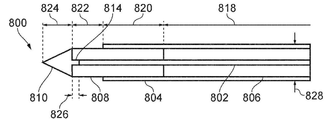
이제 도 3 및 도 4를 참조하여 본 발명의 전기 수술 시스템의 일부일 수 있는 전기 수술 기기(300)를 설명한다. 도 3 및 도 4는 위에서 언급된 원위 조립체(118)에 대응할 수 있는 전기 수술 기기(300)의 원위 부분의 측면도를 도시한다. 전기 수술 기기(300)는 가요성 동축 케이블(302), 및 동축 케이블(302)의 원위 단부에 연결되는 방사 팁 부분(304)을 포함한다. 동축 케이블(302)은 마이크로파 에너지를 운반하기에 적합한 기존의 가요성 50Ω 동축 케이블일 수 있다. 동축 케이블은 유전체 재료로 분리된 중심 전도체와 외부 전도체를 포함한다. 동축 케이블(302)은 근위 단부에서 마이크로파 에너지를 수신하기 위해 생성기에, 예를 들어, 생성기(102)에 연결될 수 있다. An
방사 팁 부분(304)은 근위 동축 전송 라인(306), 및 근위 동축 전송 라인(306)의 원위 단부에 형성된 원위 바늘 팁(308)을 포함한다. 근위 동축 전송 라인(306)은 동축 케이블(302)로부터 전자기 에너지를 수신하고 이를 원위 바늘 팁(308)으로 운반하기 위해 동축 케이블(302)의 원위 단부에 전기적으로 연결된다. 원위 바늘 팁(308)은 수신된 전자기 에너지를 표적 생물학적 조직으로 전달하도록 구성된다. 본 예에서, 원위 바늘 팁(308)은 마이크로파 에너지를 표적 생물학적 조직으로 전달하여 표적 조직을 절제하도록 반파장 변환기로서 구성된다. 다시 말해, 원위 바늘 팁(308)의 전기적 길이는 (예를 들어, 5.8GHz의) 마이크로파 에너지의 반파장에 대응한다. 마이크로파 에너지가 원위 바늘 팁(308)으로 전달될 때, 원위 바늘 팁은 마이크로파 에너지를 그 길이를 따라 주변의 생물학적 조직으로 방사할 수 있다.The
근위 동축 전송 라인(306)의 내부 전도체(310)는 동축 케이블(302)의 중심 전도체에 전기적으로 연결된다. 방사 팁 부분(304)은 동축 케이블(302)과 방사 팁 부분(304) 사이의 접합부 위에 장착된 칼라(312)를 통해 동축 케이블(302)에 고정된다. 칼라(312)는 전도성 재료(예를 들어, 황동)로 만들어지고, 동축 케이블(302)의 외부 전도체를 근위 동축 전송 라인(306)의 외부 전도체(314)에 전기적으로 연결한다. 외부 전도체(314)는 니티놀 튜브로 형성되어, 가요성이고 조직(예를 들어, 십이지장 벽)을 관통하기에 충분한 길이 방향 강성을 제공한다. 예시를 위해, 외부 전도체(314)는 방사 팁 부분(304)의 내부 구조를 드러내기 위해 도 4에서 생략되어 있다. 또한 예시를 위해, 근위 동축 전송 라인(306)의 길이는 파선(307)으로 표시된 바와 같이 도 3 및 도 4에서 생략되었다. The
근위 동축 전송 라인(306)은, 내부 전도체(310) 주위에 배치되고 외부 전도체(314)로부터 내부 전도체(310)를 이격시키는 근위 유전체 슬리브(320)를 포함한다. 외부 전도체(314)는 근위 유전체 슬리브(320)의 외부 표면에 형성된다. 원위 유전체 슬리브(322)는 원위 바늘 팁(308)을 형성하기 위해 내부 전도체(310)의 원위 부분 주위에 배치된다. 원위 바늘 팁(308)은 표적 조직 내로 방사 팁 부분이 용이하게 삽입될 수 있도록 원위 단부에 뾰족한 팁(324)을 더 포함한다. 원위 유전체 슬리브(322)는 근위 유전체 슬리브(504)에 비해 상이한 유전체 재료로 제조될 수 있다. 일례에서, 근위 유전체 슬리브(504)는 PTFE로 만들어질 수 있고(예를 들어, PTFE 튜브일 수 있음) 원위 유전체 슬리브는 PEEK로 만들어질 수 있다. 방사 팁 부분(304)에 사용될 수 있는 재료의 특정 예는 도 7 내지 도 11과 관련하여 아래에서 논의된다. The proximal
외부 전도체(314)의 원위 부분은 원위 유전체 슬리브(322)의 근위 부분 위에 놓인다. 이러한 방식으로, 근위 동축 전송 라인(306)의 원위 부분은 원위 유전체 슬리브(322)의 근위 부분을 포함한다. 근위 및 원위 유전체 슬리브의 재료 및 외부 전도체(314)와 원위 유전체 슬리브(322) 사이의 중첩 길이는 방사 팁 부분(308)의 전기적 길이 및 표적 조직과의 임피던스 매칭을 조정하기 위해 선택될 수 있다.A distal portion of
칼라(312)는, 동축 케이블(302)의 원위 단부에 장착되고 동축 케이블(302)의 외부 전도체에 전기적으로 연결된 실질적으로 원통형인 몸체(316)를 포함한다. 칼라(312)는 칼라(312)의 몸체(316)로부터 근위 동축 전송 라인(306)의 외부 전도체(314)의 근위 단부까지 연장되는 원위 부분(318)을 더 포함한다. 칼라(312)의 원위 부분(318)은 둥근 원위 표면을 포함한다. 이것은 동축 케이블(302)과 방사 팁 부분(304) 사이의 인터페이스에서 날카로운 에지를 피함으로써 전기 수술 기기(300)가 채널을 따라 이동할 때 전기 수술 기기(300)와 수술용 관찰 디바이스의 기기 채널 사이의 마찰을 감소시킬 수 있다. 이것은 또한 채널이 역굴곡될 때 채널을 따라 전기 수술 기기를 이동시키는 것을 용이하게 할 수 있다.The
방사 팁 부분(304)의 최대 외부 직경은 도 3에 화살표(326)로 표시되어 있다. 본 예에서, 방사 팁 부분(304)의 최대 외부 직경은 외부 전도체가 가장 큰 외부 직경을 갖는 방사 팁 부분(304)의 구성 요소이기 때문에 외부 전도체(314)의 외부 직경에 대응한다. 방사 팁 부분(304)의 최대 외부 직경은 1.0mm 이하이다. 예를 들어, 최대 외부 직경은 1.0mm, 0.95mm 또는 0.90mm일 수 있다. 이것은 방사 팁 부분이 표적 조직에 삽입될 때 방사 팁 부분(304)에 의해 생성되는 삽입 구멍의 크기를 작게 하여 출혈을 최소화할 수 있는 것을 보장할 수 있다. 이것은 과도한 출혈이 문제 시 될 수 있는 영역, 즉 신체에서 매우 혈관이 많은 영역, 예를 들어, 간에 전기 수술 기기(300)를 사용하기에 특히 적합하게 할 수 있다.The maximum outer diameter of the
동축 케이블(302)의 외부 직경은 도 3에서 화살표(328)로 표시되어 있다. 동축 케이블(302)의 외부 직경은 방사 팁 부분(304)의 최대 외부 직경보다 크다. 예를 들어, 동축 케이블(302)의 외부 직경은 1.19mm 내지 2.0mm일 수 있고, 또는 2.0mm보다 클 수 있다. 동축 케이블보다 작은 최대 외부 직경을 갖는 방사 팁 부분(304)을 제공함으로써, 동축 케이블(302)에 대한 방사 팁 부분(304)의 가요성을 증가시키는 것이 가능하다. 이것은 방사 팁 부분(304)을 특정 치료 위치로 조종하는 것을 용이하게 할 수 있다. 동시에, 전송 손실은 일반적으로 동축 케이블(302)의 직경과 관련되기 때문에, 큰 직경을 갖는 동축 케이블(302)을 제공함으로써, 동축 케이블(302)에서 (예를 들어, 가열로 인한) 전송 손실을 감소시킬 수 있다. 이것은 동축 케이블(302)을 따라 방사 팁 부분(304)으로 마이크로파 에너지를 보다 효율적으로 운반할 수 있다.The outer diameter of the
일부 실시예에서, 전기 수술 기기(300)는 카테터(도시되지 않음)에 수용될 수 있다. 전기 수술 기기(300)는 방사 팁 부분(304)이 사용 중이 아닐 때 카테터 내부로 후퇴될 수 있도록 카테터에 대해 이동 가능할 수 있다. 이것은 방사 팁 부분을 보호하는 역할을 할 수 있고, 방사 팁 부분이 수술용 관찰 디바이스의 삽입 코드에 삽입될 때 방사 팁 부분이 삽입 코드에 걸리는 것을 방지할 수 있다.In some embodiments, the
방사 팁 부분(304)은 30mm 이상의 길이, 예를 들어, 40mm의 길이를 가질 수 있다. 이러한 방식으로, 방사 팁 부분(304)은 동축 케이블(302)의 일부를 조직에 삽입할 필요 없이 원위 바늘 팁(308)이 치료 부위에 도달하기에 충분히 길 수 있다. 일부 경우에, 방사 팁 부분(304)은 140mm 이상의 길이를 가질 수 있다. 본 발명자들은 이것이 삽입 코드의 원위 부분을 통해 보다 강성인 동축 케이블(302)을 밀어야 하는 것을 피할 수 있기 때문에, 삽입 코드의 원위 부분이 역굴곡되는 곳에서 삽입 코드 내로 전기 수술 기기(300)를 삽입하는 것을 용이하게 할 수 있다는 것을 발견하였다.The radiating
도 5는 근위 유전체 슬리브(320)와 원위 유전체 슬리브(322) 사이의 인터페이스를 보다 상세하게 도시한다. 도 5는 방사 팁 부분(304)의 원위 구획의 단면도를 도시한다. 예시를 위해, 외부 전도체(314)는 도 5에서 생략되어 있다. 원위 유전체 슬리브(322)의 근위 단부는 원위 유전체 슬리브(322)의 근위 단부로부터 연장되는 돌출부(502)를 포함한다. 돌출부(502)는 원위 유전체 슬리브(322)의 외부 직경보다 작은 외부 직경을 갖는 일반적으로 원통형인 형상을 갖고, 내부 전도체(310) 주위에 배치된다. 근위 유전체 슬리브(320)는, 돌출부(502)의 형상과 상보적인 형상을 갖고 돌출부(502)를 수용하는 공동을 포함한다. 따라서, 근위 유전체 슬리브(320)는 돌출부(502) 주위를 단계적으로 이동한다. 원위 유전체 슬리브(322)의 돌출부(502)가 근위 유전체 슬리브(320)에 수용될 때, 이는 원위 유전체 슬리브와 근위 유전체 슬리브 사이에 강력한 기계적 연결을 제공하는 역할을 한다. 추가적으로, 돌출부(502)는 원위 유전체 슬리브(322)와 근위 유전체 슬리브(320) 사이의 인터페이스에서 방사 팁 부분(304)의 항복 전압을 증가시키는 역할을 할 수 있다. 이것은 방사 팁 부분(304)의 전기적 안전성을 향상시킬 수 있다.5 shows the interface between the proximal
전기 수술 기기의 방사 팁 부분(304)은 작은 직경(즉, 1.0mm 이하)을 가지므로 방사 팁 부분에 마이크로파 에너지가 전달될 때 방사 팁 부분은 빠르게 가열될 수 있다. 이것은 원위 바늘 팁에 마이크로파 에너지의 전달 효율을 저하시킬 수 있다. 또한 방사 팁 부분(304)이 가열되면 건강한 주변 조직에 손상을 일으킬 수 있다. 본 발명자들은 마이크로파 에너지를 펄스로 전달하도록 본 발명의 전기 수술 시스템의 전기 수술용 생성기(예를 들어, 전기 수술용 생성기(102))를 구성함으로써 이러한 단점을 극복하였다. 본 발명자들은 마이크로파 에너지를 펄스로 전달하면 방사 팁 부분이 가열되는 효과를 피하거나 감소시켜 수술 시술 동안 방사 팁 부분을 허용 가능한 온도로 유지할 수 있다는 것을 발견하였다.Since the
마이크로파 에너지를 인가하는 동안 방사 팁 부분이 가열되는 것을 피하기 위해, 마이크로파 펄스의 펄스 지속 시간은 방사 팁 부분의 열 응답 시간보다 크게 설정될 수 있다. 이러한 방식으로, 방사 팁 부분은 마이크로파 펄스의 시간 규모에서 펄스형 마이크로파 에너지에 열적으로 반응할 시간이 없을 수 있다. 방사 팁 부분의 열 응답 시간은 주어진 전력 레벨(예를 들어, 전기 수술 시술 동안 사용되는 전력 레벨)의 마이크로파 에너지가 방사 팁 부분에 전달될 때 방사 팁 부분의 온도가 주어진 양(예를 들어, 5℃)만큼 증가하는 데 드는 시간 기간을 결정함으로써 실험적으로 측정될 수 있다. 이에 따라 펄스 지속 시간은 방사 팁 부분의 온도가 전기 수술 시술 동안 허용 가능한 온도로 유지되는 것을 보장하도록 설정될 수 있다.In order to avoid heating the radiation tip portion while applying microwave energy, the pulse duration of the microwave pulse may be set to be greater than the thermal response time of the radiation tip portion. In this way, the radiating tip portion may not have time to thermally respond to pulsed microwave energy on the time scale of the microwave pulse. The thermal response time of the radiating tip portion is such that the temperature of the radiating tip portion is a given amount (e.g., 5 °C) can be determined empirically by determining the period of time it takes to increase by Accordingly, the pulse duration can be set to ensure that the temperature of the radiating tip portion is maintained at an acceptable temperature during the electrosurgical procedure.
본 발명자들은 25% 이하의 듀티 사이클로 펄스형 마이크로파 에너지를 전달하도록 전기 수술용 생성기를 구성하면 사용 동안 방사 팁 부분이 가열되는 효과를 피하거나 감소시켜 방사 팁 부분을 허용 가능한 온도로 유지할 수 있다는 것을 발견하였다. 전기 수술용 생성기는 다음의 예시적인 사이클 중 하나에 따라 마이크로파 에너지를 전달하도록 구성될 수 있다:The inventors have found that configuring an electrosurgical generator to deliver pulsed microwave energy with a duty cycle of 25% or less can avoid or reduce the effect of heating the radiating tip portion during use, thereby maintaining the radiating tip portion at an acceptable temperature. did The electrosurgical generator may be configured to deliver microwave energy according to one of the following exemplary cycles:
a) 10ms 펄스 지속 시간, 펄스 간 90ms;a) 10 ms pulse duration, 90 ms between pulses;
b) 10ms 펄스 지속 시간, 펄스 간 50ms;b) 10 ms pulse duration, 50 ms between pulses;
c) 10ms 펄스 지속 시간, 펄스 간 30ms;c) 10 ms pulse duration, 30 ms between pulses;
d) 100ms 펄스 지속 시간, 펄스 간 900ms;d) 100 ms pulse duration, 900 ms between pulses;
e) 100ms 펄스 지속 시간, 펄스 간 500ms;e) 100 ms pulse duration, 500 ms between pulses;
f) 100ms 펄스 지속 시간, 펄스 간 300ms; 및f) 100 ms pulse duration, 300 ms between pulses; and
g) 200ms 펄스 지속 시간, 펄스 간 800ms.g) 200 ms pulse duration, 800 ms between pulses.
사이클 a) 및 d)는 10%의 듀티 사이클에 대응한다; 사이클 b) 및 e)는 16.67%의 듀티 사이클에 대응한다; 사이클 c) 및 f)는 25%의 듀티 사이클에 대응한다; 사이클 g)는 20%의 듀티 사이클에 대응한다.Cycles a) and d) correspond to a duty cycle of 10%; Cycles b) and e) correspond to a duty cycle of 16.67%; Cycles c) and f) correspond to a duty cycle of 25%; Cycle g) corresponds to a duty cycle of 20%.
도 6은 위에 주어진 사이클 a)에 따른 전력 전달 프로파일을 예시한다. 도 6의 전력 전달 프로파일은 시간에 따른 전기 수술용 생성기에 의해 공급되는 마이크로파 에너지의 전력을 나타낸다. 전력 전달 프로파일은 10ms의 지속 시간을 각각 갖는 일련의 마이크로파 펄스(600)를 포함한다. 마이크로파 펄스(600)는 90ms의 지속 시간을 각각 갖는 간격(602)에 의해 분리된다. 마이크로파 펄스(600)는 각각 도 6에 나타낸 바와 같이 전력(P)을 갖는다. 간격(602) 동안에는 전기 수술용 생성기에 의해 마이크로파 에너지가 공급되지 않는다(즉, 공급된 전력은 0W이다). 펄스(600) 각각은 동일하고 일정한 전력 레벨을 포함한다. 도 6의 전력 전달 프로파일은 축척에 맞게 그려진 것이 아닌 것으로 이해된다. 다른 예에서, 마이크로파 펄스의 전력 레벨은 원하는 에너지 전달 프로파일에 따라 펄스 동안 변할 수 있다. 일부 경우에, 마이크로파 펄스 사이클은 상이한 지속 시간 및/또는 전력 레벨을 갖는 펄스를 포함할 수 있다.6 illustrates the power delivery profile according to cycle a) given above. The power delivery profile of FIG. 6 represents the power of microwave energy supplied by the electrosurgical generator over time. The power delivery profile includes a series of
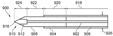
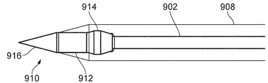
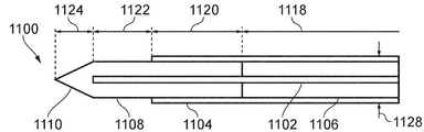
이제 도 7 내지 도 11을 참조하여 본 발명의 전기 수술 시스템에서 사용될 수 있는 전기 수술 기기의 방사 팁 부분의 특정 예를 설명한다. 아래에 설명된 방사 팁 부분은, 예를 들어, 위에서 설명된 전기 수술 기기(300)의 방사 팁 부분(304) 대신에 사용될 수 있다. 아래에서 논의되는 방사 팁 부분(700, 800, 900, 1000 및 1100)은 각각 유사한 전체 구성을 갖는다. 방사 팁 부분(304)과 유사하게, 각각의 방사 팁 부분(700, 800, 900, 1000, 1100)은 동축 케이블(도시되지 않음)의 중심 전도체에 전기적으로 연결된 내부 전도체, 및 동축 케이블의 외부 전도체에 전기적으로 연결된 외부 전도체를 갖는다. 방사 팁 부분(700, 800, 900, 1000 및 1100) 각각은, 방사 팁 부분(304)과 관련하여 위에서 논의된 근위 전송 라인 및 원위 바늘 팁을 형성하기 위해, 내부 전도체 주위에 배치된 근위 유전체 슬리브 및 원위 유전체 슬리브를 더 포함한다.A specific example of a radiating tip portion of an electrosurgical instrument that may be used in the electrosurgical system of the present invention will now be described with reference to FIGS. 7 to 11 . The radiating tip portion described below may be used, for example, in place of the
도 7은 방사 팁 부분(700)의 원위 구획의 단면도를 도시한다. 방사 팁 부분(700)의 근위 유전체 슬리브(706)는 가요성 절연 재료, 예를 들어, PTFE로 제조될 수 있다. 방사 팁 부분(700)의 원위 유전체 슬리브(708)는 지르코니아의 원통형 부재로 만들어진다. 원위 유전체 슬리브(708)의 원위 팁(710)은 조직 내로 방사 팁 부분(700)이 삽입되는 것을 용이하게 하기 위해 날카롭게 형성된다. 지르코니아로 원위 유전체 슬리브(708)를 제조하면 방사 팁 부분(700)에 강성의 원위 바늘 팁을 제공할 수 있어서 조직의 관통을 용이하게 할 수 있다. 또한 지르코니아를 사용하면 원하는 전기적 길이를 유지하면서 방사 팁 부분의 물리적 길이를 단축시킬 수 있다.7 shows a cross-sectional view of the distal section of the
방사 팁 부분(700)의 예시적인 치수가 도 7에 도시되어 있다. 근위 유전체 슬리브(706)의 길이에 대응하는 참조 번호(712)로 표시된 치수는 37mm일 수 있다. 근위 유전체 슬리브(706)의 전체 길이는 도 7에 도시되어 있지 않는 것으로 이해된다. 방사 팁 부분(700)의 외부 전도체(704)와 원위 유전체 슬리브(708) 사이의 중첩 부분에 대응하는 참조 번호(714)로 표시된 치수는 3.6mm일 수 있다. 외부 전도체(704)의 원위 단부를 넘어 돌출된 방사 팁 부분(700)의 내부 전도체(702)의 길이에 대응하는 참조 번호(716)로 표시된 치수는 1.5mm일 수 있다. 원위 팁(710)의 길이에 대응하는 참조 번호(718)로 표시된 치수는 1.5mm일 수 있다. 참조 번호(720)로 표시된 방사 팁 부분(700)의 최대 외부 직경은 1.0mm 이하이다.Exemplary dimensions of a
도 8a는 방사 팁 부분(800)의 원위 구획의 단면도를 도시한다. 방사 팁 부분(800)의 근위 유전체 슬리브(806)는 절연 재료, 예를 들어, PTFE의 가요성 튜브로 제조될 수 있다. 방사 팁 부분(800)의 원위 유전체 슬리브(808)는 지르코니아의 원통형 부재로 만들어진다. 원위 유전체 슬리브(808)는 내부 전도체를 수용하는 보어를 포함한다. 지르코니아로 만들어진 원위 팁(810)은 원위 유전체 슬리브(808)의 원위 단부에 장착된다. 원위 팁(810)의 사시도가 도 8b에 도시되어 있다. 원위 팁(810)은 조직 내로 방사 팁 부분(800)이 삽입되는 것을 용이하게 하기 위해 뾰족한 팁을 형성하는 원추형 몸체(812)를 갖는다. 원위 팁(810)은 원추형 몸체(812)의 근위면(816)으로부터 연장되는 돌출부(814)를 포함한다. 원위 팁(810)의 돌출부는 원위 유전체 슬리브(808)의 보어에 수용되고 여기서 제자리에 (예를 들어, 접착제로) 고정된다.8A shows a cross-sectional view of the distal section of the
방사 팁 부분(800)의 예시적인 치수가 도 8a에 도시되어 있다. 근위 유전체 슬리브(806)의 길이에 대응하는 참조 번호(818)로 표시된 치수는 37mm일 수 있다. 근위 유전체 슬리브(806)의 전체 길이는 도 8a에 도시되어 있지 않는 것으로 이해된다. 방사 팁 부분(800)의 외부 전도체(804)와 원위 유전체 슬리브(808) 사이의 중첩 부분에 대응하는 참조 번호(820)로 표시된 치수는 3.6mm일 수 있다. 외부 전도체(804)의 원위 단부를 넘어 돌출되는 원위 유전체 슬리브(808)의 길이에 대응하는 참조 번호(822)로 표시된 치수는 2.0mm일 수 있다. 원위 팁(810)의 원추형 몸체(812)의 길이에 대응하는 참조 번호(824)로 표시된 치수는 1.5mm일 수 있다. 돌출부(814)의 길이에 대응하는 참조 번호(826)로 표시된 치수는 0.5mm일 수 있다. 참조번호(828)로 표시된 방사 팁 부분(800)의 최대 외부 직경은 1.0mm 이하이다.Exemplary dimensions of a
도 9a는 방사 팁 부분(900)의 원위 구획의 단면도를 도시한다. 방사 팁 부분(900)의 근위 유전체 슬리브(906)는 절연 재료, 예를 들어, PTFE의 가요성 튜브로 제조될 수 있다. 방사 팁 부분(900)의 원위 유전체 슬리브(908)는 폴리에테르 에테르 케톤(PEEK)의 원통형 부재로 만들어진다. 원위 유전체 슬리브(908)는 지르코니아로 제조된 원위 팁(910)을 수용하는 공동을 원위 단부에 포함한다. 원위 팁(910)과 원위 유전체 슬리브(908) 사이에 "압입(push-fit)" 연결이 형성된다.9A shows a cross-sectional view of the distal section of the
도 9b는 원위 팁(910)과 원위 유전체 슬리브(908) 사이의 연결을 보다 상세하게 도시한다. 원위 팁은 원위 유전체 슬리브(908)의 공동에 수용되는 몸체(912)를 포함한다. 몸체(912)는 공동 내에 원위 팁(910)을 유지하기 위해 원위 유전체 슬리브(908)에 대해 외측으로 가압하도록 배열된 범프(914)를 외부 표면에 포함한다. 따라서, 원위 팁(910)은 일단 공동 내로 삽입되면 공동 내에 자동으로 유지될 수 있다. 나아가 원위 팁(910)은 접착제를 사용하여 공동 내에 고정될 수 있다. 원위 팁(910)은 방사 팁 부분(900)의 원위 단부에서 뾰족한 팁을 형성하는 원추형 부분(916)을 더 포함한다. 원위 유전체 슬리브(908)의 외부 표면은 방사 팁 부분(900)의 외부 표면이 평활하도록 원추형 부분(916)의 테이퍼링 각도와 일치하는 각도로 테이퍼링진다. 지르코니아는 PEEK보다 높은 강성을 가질 수 있기 때문에 원위 팁(910)을 지르코니아로 만들면 더 날카로운 원위 팁을 제공할 수 있다.9B shows the connection between the
방사 팁 부분(900)의 예시적인 치수가 도 9a에 도시되어 있다. 근위 유전체 슬리브(906)의 길이에 대응하는 참조 번호(918)로 표시된 치수는 37mm일 수 있다. 근위 유전체 슬리브(906)의 전체 길이는 도 9a에 도시되어 있지 않은 것으로 이해된다. 방사 팁 부분(900)의 외부 전도체(904)와 원위 유전체 슬리브(908) 사이의 중첩 부분에 대응하는 참조 번호(920)로 표시된 치수는 7.0mm일 수 있다. 외부 전도체(904)의 원위 단부를 넘어 돌출된 방사 팁 부분(900)의 내부 전도체(902)의 길이에 대응하는 참조 번호(922)로 표시된 치수는 5.0mm일 수 있다. 원위 팁(910)의 길이에 대응하는 참조 번호(924)로 표시된 치수는 2.0mm일 수 있다. 참조 번호(926)로 표시된 방사 팁 부분(900)의 최대 외부 직경은 1.0mm 이하이다.Exemplary dimensions of a
도 10은 방사 팁 부분(1000)의 원위 구획의 단면도를 도시한다. 방사 팁 부분(1000)의 근위 유전체 슬리브(1006)는 절연 재료, 예를 들어, PTFE의 가요성 튜브로 제조될 수 있다. 방사 팁 부분(1000)의 원위 유전체 슬리브(1008)는 PEEK의 원통형 부재로 만들어진다. 방사 팁 부분(800)과 유사하게, 방사 팁(1000)은 원위 유전체 슬리브(1008)의 원위 단부에 장착된 지르코니아로 제조된 원위 팁(1010)을 포함한다. 원위 팁(1010)은 도 8b에 도시된 원위 팁(810)과 유사한 구성을 갖고, 즉 원위 팁은 원위 유전체 슬리브(1008)의 보어에 수용되는 돌출부(1014) 및 원추형 몸체를 포함한다.10 shows a cross-sectional view of the distal section of the radiating tip portion 1000 . The
방사 팁 부분(1000)의 예시적인 치수가 도 10에 도시되어 있다. 근위 유전체 슬리브(1006)의 길이에 대응하는 참조 번호(1018)로 표시된 치수는 37mm일 수 있다. 근위 유전체 슬리브(1006)의 전체 길이는 도 10에 도시되어 있지 않은 것으로 이해된다. 방사 팁 부분(1000)의 외부 전도체(1004)와 원위 유전체 슬리브(1008) 사이의 중첩 부분에 대응하는 참조 번호(1020)로 표시된 치수는 6.0mm일 수 있다. 외부 전도체(1004)의 원위 단부를 넘어 돌출된 원위 유전체 슬리브(1008)의 길이에 대응하는 참조 번호(1022)로 표시된 치수는 5.5mm일 수 있다. 원위 팁(810)의 원추형 몸체의 길이에 대응하는 참조 번호(1024)로 표시된 치수는 1.5mm일 수 있다. 돌출부(1014)의 길이에 대응하는 참조 번호(1026)의 치수는 0.5mm일 수 있다. 참조 번호(1028)로 표시된 방사 팁 부분(1000)의 최대 외부 직경은 1.0mm 이하이다.Exemplary dimensions of a radiating tip portion 1000 are shown in FIG. 10 . The dimension indicated by
도 11은 방사 팁 부분(1100)의 원위 구획의 단면도를 도시한다. 방사 팁 부분(1100)의 근위 유전체 슬리브(1106)는 절연 재료, 예를 들어, PTFE의 가요성 튜브로 제조될 수 있다. 방사 팁 부분(1100)의 원위 유전체 슬리브(1108)는 PEEK의 원통형 부재로 만들어진다. 원위 유전체 슬리브(1108)의 원위 팁(1110)은 조직 내로 방사 팁 부분(1100)이 삽입되는 것을 용이하게 하기 위해 날카롭게 형성된다. 11 shows a cross-sectional view of the distal section of the
방사 팁 부분(1100)의 예시적인 치수가 도 11에 도시되어 있다. 근위 유전체 슬리브(1106)의 길이에 대응하는 참조 번호(1118)로 표시된 치수는 37mm일 수 있다. 근위 유전체 슬리브(1106)의 전체 길이는 도 11에 도시되어 있지 않은 것으로 이해된다. 방사 팁 부분(1000)의 외부 전도체(1104)와 원위 유전체 슬리브(1108) 사이의 중첩 부분에 대응하는 참조 번호(1120)로 표시된 치수는 6.0mm일 수 있다. 외부 전도체(1004)의 원위 단부를 넘어 돌출된 방사 팁 부분(1100)의 내부 전도체(1102)의 길이에 대응하는 참조 번호(1122)로 표시된 치수는 5.5mm일 수 있다. 원위 팁(1110)의 길이에 대응하는 참조 번호(1024)로 표시된 치수는 1.5mm일 수 있다. 참조 번호(1028)로 표시된 방사 팁 부분(1100)의 최대 외부 직경은 1.0mm 이하이다.Exemplary dimensions of a
도 12는 초음파 가능 기관지경과 같은 수술용 관찰 디바이스의 삽입 코드(120)의 원위 단부의 개략적인 단면도이다. 삽입 코드(120)는 전기 수술 기기(700)를 수용하기 위한 기기 채널(132)을 형성하는 루멘을 포함한다. 이 예에서는 도 7의 기기가 도시되어 있지만, 위에 설명된 구성 중 임의의 구성을 사용할 수 있다. 이 예에서 전기 수술 기기(700)는 전기 수술 기기(700)의 외부 표면 주위에 놓인 가요성 튜브인 보호 카테터(1202)를 포함한다. 보호 카테터(1202)는 기기의 뾰족한 팁(710)으로부터 기기 채널(132)의 내부 표면을 보호한다. 이것은 삽입 코드가 치료 부위로 가는 도중에 구부러진 경우에 특히 유용할 수 있다. 보호 카테터(1202)는 방사 팁이 기기 채널의 내부 표면에 걸리지 않고 기기 채널 주위를 만곡하는 것을 도울 수 있다.12 is a schematic cross-sectional view of the distal end of an
사용 시, 기기(700)는 보호 카테터(1202)를 넘어 삽입 코드(120)의 원위 단부로부터 돌출하도록 연장 가능(예를 들어, 활주 가능)하고, 여기서 조직을 관통하여 이 치료 부위에 도달할 수 있다. 치료 부위에 정확히 배치되는 것을 돕기 위해 기관지경의 초음파 이미징 기능을 사용하여 방사 팁을 관찰할 수 있다.In use, the
Claims (11)
마이크로파 에너지를 공급하도록 구성된 전기 수술용 생성기;
신체 내의 치료 부위에 최소 침습적 삽입을 위한 조향 가능한 삽입 코드를 갖는 수술용 관찰 디바이스; 및
상기 삽입 코드 내에 위치된 기기 채널에 맞는 치수의 전기 수술 기기를 포함하고,
상기 전기 수술 기기는,
상기 마이크로파 에너지를 운반하도록 배열된 가요성 동축 케이블; 및
상기 동축 케이블의 원위 단부에 연결되고 상기 마이크로파 에너지를 수신하도록 구성된 방사 팁 부분(radiating tip portion)을 포함하고, 상기 방사 팁 부분의 최대 외부 직경은 1.0mm 이하이고, 상기 방사 팁 부분의 최대 외부 직경은 상기 동축 케이블의 외부 직경보다 더 작고,
상기 방사 팁 부분은,
상기 마이크로파 에너지를 운반하기 위한 근위 동축 전송 라인; 및
상기 근위 동축 전송 라인의 원위 단부에 장착된 원위 바늘 팁을 포함하고, 상기 전기 수술 기기는 상기 기기 채널의 원위 단부를 넘어 상기 원위 바늘 팁을 연장시켜 생물학적 조직을 천공하도록 상기 기기 채널 내에서 활주 가능하고, 상기 원위 바늘 팁은 상기 마이크로파 에너지를 생물학적 조직으로 전달하도록 배열된, 전기 수술 시스템.An electrosurgical system for treating biological tissue, comprising:
an electrosurgical generator configured to supply microwave energy;
a surgical observation device having a steerable insertion cord for minimally invasive insertion into a treatment site within the body; and
an electrosurgical instrument dimensioned to fit an instrument channel positioned within the insert cord;
The electrosurgical device comprises:
a flexible coaxial cable arranged to carry the microwave energy; and
a radiating tip portion connected to the distal end of the coaxial cable and configured to receive the microwave energy, the maximum outer diameter of the radiating tip portion being less than or equal to 1.0 mm, the maximum outer diameter of the radiating tip portion being is smaller than the outer diameter of the coaxial cable,
The radiation tip portion,
a proximal coaxial transmission line for carrying the microwave energy; and
a distal needle tip mounted to the distal end of the proximal coaxial transmission line, wherein the electrosurgical instrument is slidable within the instrument channel to extend the distal needle tip beyond the distal end of the instrument channel to puncture biological tissue and wherein the distal needle tip is arranged to deliver the microwave energy to a biological tissue.
상기 가요성 동축 케이블의 원위 단부로부터 연장되는 내부 전도체로서, 상기 가요성 동축 케이블의 중심 전도체에 전기적으로 연결된 상기 내부 전도체;
상기 내부 전도체 주위에 장착된 근위 유전체 슬리브; 및
상기 근위 유전체 주위에 장착된 외부 전도체를 포함하고,
상기 원위 바늘 팁은 상기 내부 전도체 주위에 장착된 원위 유전체 슬리브를 포함하고,
상기 외부 전도체의 원위 부분은 상기 원위 유전체 슬리브의 근위 부분 위에 놓인, 전기 수술 시스템.8. The method of any one of claims 1 to 7, wherein the proximal coaxial transmission line comprises:
an inner conductor extending from the distal end of the flexible coaxial cable, the inner conductor electrically connected to a center conductor of the flexible coaxial cable;
a proximal dielectric sleeve mounted around the inner conductor; and
an outer conductor mounted around the proximal dielectric;
wherein the distal needle tip comprises a distal dielectric sleeve mounted around the inner conductor;
and the distal portion of the outer conductor overlies the proximal portion of the distal dielectric sleeve.
Applications Claiming Priority (3)
| Application Number | Priority Date | Filing Date | Title |
|---|---|---|---|
| GB1906008.6A GB2583490A (en) | 2019-04-30 | 2019-04-30 | Electrosurgical system |
| GB1906008.6 | 2019-04-30 | ||
| PCT/EP2020/061762 WO2020221749A1 (en) | 2019-04-30 | 2020-04-28 | Electrosurgical system |
Publications (1)
| Publication Number | Publication Date |
|---|---|
| KR20220002893A true KR20220002893A (en) | 2022-01-07 |
Family
ID=66809117
Family Applications (1)
| Application Number | Title | Priority Date | Filing Date |
|---|---|---|---|
| KR1020217033185A KR20220002893A (en) | 2019-04-30 | 2020-04-28 | electrosurgical system |
Country Status (11)
| Country | Link |
|---|---|
| US (1) | US20220202490A1 (en) |
| EP (1) | EP3962391A1 (en) |
| JP (1) | JP2022531099A (en) |
| KR (1) | KR20220002893A (en) |
| CN (1) | CN113710185A (en) |
| AU (1) | AU2020264738A1 (en) |
| CA (1) | CA3136874A1 (en) |
| GB (1) | GB2583490A (en) |
| IL (1) | IL287309A (en) |
| SG (1) | SG11202111407SA (en) |
| WO (1) | WO2020221749A1 (en) |
Families Citing this family (6)
| Publication number | Priority date | Publication date | Assignee | Title |
|---|---|---|---|---|
| GB2601789A (en) | 2020-12-10 | 2022-06-15 | Creo Medical Ltd | Raman spectroscopy probe, Raman spectroscopy apparatus including the Raman spectroscopy probe and elongate assembly |
| GB2603789A (en) | 2021-02-12 | 2022-08-17 | Creo Medical Ltd | Raman spectroscopy probe, Raman spectroscopy apparatus including the Raman spectroscopy probe and elongate assembly |
| GB202114356D0 (en) | 2021-10-07 | 2021-11-24 | Creo Medical Ltd | Raman spectroscopy probe and raman spectroscopy apparatus |
| US20230210579A1 (en) * | 2021-12-30 | 2023-07-06 | Verb Surgical Inc. | Real-time surgical tool presence/absence detection in surgical videos |
| CN114569242A (en) * | 2022-03-05 | 2022-06-03 | 南京德文医学科技有限公司 | Non-water-cooled microwave ablation catheter |
| CN115778526B (en) * | 2022-07-11 | 2023-08-29 | 南京康友医疗科技有限公司 | Microwave, radio frequency and temperature measurement integrated ablation needle |
Family Cites Families (13)
| Publication number | Priority date | Publication date | Assignee | Title |
|---|---|---|---|---|
| US5403311A (en) * | 1993-03-29 | 1995-04-04 | Boston Scientific Corporation | Electro-coagulation and ablation and other electrotherapeutic treatments of body tissue |
| US8068921B2 (en) * | 2006-09-29 | 2011-11-29 | Vivant Medical, Inc. | Microwave antenna assembly and method of using the same |
| US8343149B2 (en) * | 2008-06-26 | 2013-01-01 | Vivant Medical, Inc. | Deployable microwave antenna for treating tissue |
| CN102245119B (en) * | 2008-10-21 | 2017-06-06 | 微立方有限责任公司 | Energy is applied to the method and device of bodily tissue |
| GB201021032D0 (en) | 2010-12-10 | 2011-01-26 | Creo Medical Ltd | Electrosurgical apparatus |
| WO2013149245A1 (en) * | 2012-03-31 | 2013-10-03 | Microcube, Llc | Returned power for microwave applications |
| US20160051221A1 (en) * | 2014-08-25 | 2016-02-25 | Covidien Lp | System and Method for Planning, Monitoring, and Confirming Treatment |
| GB2545465A (en) * | 2015-12-17 | 2017-06-21 | Creo Medical Ltd | Electrosurgical probe for delivering microwave energy |
| US11000332B2 (en) * | 2016-08-02 | 2021-05-11 | Covidien Lp | Ablation cable assemblies having a large diameter coaxial feed cable reduced to a small diameter at intended site |
| EP3381393A1 (en) * | 2017-03-31 | 2018-10-03 | National University of Ireland Galway | An ablation probe |
| US20180360538A1 (en) * | 2017-06-20 | 2018-12-20 | Covidien Lp | Tapered tubular members for laparoscopic microwave ablation instruments |
| GB2569812A (en) * | 2017-12-27 | 2019-07-03 | Creo Medical Ltd | Electrosurgical ablation instrument |
| GB2578576B (en) * | 2018-10-30 | 2022-08-24 | Creo Medical Ltd | Electrosurgical instrument |
-
2019
- 2019-04-30 GB GB1906008.6A patent/GB2583490A/en not_active Withdrawn
-
2020
- 2020-04-28 CN CN202080030117.8A patent/CN113710185A/en active Pending
- 2020-04-28 US US17/594,510 patent/US20220202490A1/en active Pending
- 2020-04-28 KR KR1020217033185A patent/KR20220002893A/en unknown
- 2020-04-28 CA CA3136874A patent/CA3136874A1/en active Pending
- 2020-04-28 WO PCT/EP2020/061762 patent/WO2020221749A1/en unknown
- 2020-04-28 EP EP20722563.2A patent/EP3962391A1/en active Pending
- 2020-04-28 AU AU2020264738A patent/AU2020264738A1/en active Pending
- 2020-04-28 JP JP2021562018A patent/JP2022531099A/en active Pending
- 2020-04-28 SG SG11202111407SA patent/SG11202111407SA/en unknown
-
2021
- 2021-10-17 IL IL287309A patent/IL287309A/en unknown
Also Published As
| Publication number | Publication date |
|---|---|
| SG11202111407SA (en) | 2021-11-29 |
| CN113710185A (en) | 2021-11-26 |
| CA3136874A1 (en) | 2020-11-05 |
| EP3962391A1 (en) | 2022-03-09 |
| GB2583490A (en) | 2020-11-04 |
| WO2020221749A1 (en) | 2020-11-05 |
| JP2022531099A (en) | 2022-07-06 |
| IL287309A (en) | 2021-12-01 |
| US20220202490A1 (en) | 2022-06-30 |
| GB201906008D0 (en) | 2019-06-12 |
| AU2020264738A1 (en) | 2021-11-11 |
Similar Documents
| Publication | Publication Date | Title |
|---|---|---|
| CN108495596B (en) | Electrosurgical probe for delivering microwave energy | |
| KR20220002893A (en) | electrosurgical system | |
| JP7427263B2 (en) | electrosurgical equipment | |
| EP3890639B1 (en) | Electrosurgical instrument | |
| KR20220002906A (en) | electrosurgical system | |
| KR20210010898A (en) | Electrosurgical resection instruments | |
| RU2779032C1 (en) | Electrosurgical instrument | |
| RU2772684C1 (en) | Electrosurgical instrument | |
| GB2605551A (en) | Handpiece for an electrosurgical instrument |