KR20210141714A - Filter media with improved dust loading - Google Patents
Filter media with improved dust loading Download PDFInfo
- Publication number
- KR20210141714A KR20210141714A KR1020217034989A KR20217034989A KR20210141714A KR 20210141714 A KR20210141714 A KR 20210141714A KR 1020217034989 A KR1020217034989 A KR 1020217034989A KR 20217034989 A KR20217034989 A KR 20217034989A KR 20210141714 A KR20210141714 A KR 20210141714A
- Authority
- KR
- South Korea
- Prior art keywords
- layer
- fibers
- filter material
- filter
- downstream
- Prior art date
Links
Images


Classifications
-
- B—PERFORMING OPERATIONS; TRANSPORTING
- B01—PHYSICAL OR CHEMICAL PROCESSES OR APPARATUS IN GENERAL
- B01D—SEPARATION
- B01D39/00—Filtering material for liquid or gaseous fluids
- B01D39/14—Other self-supporting filtering material ; Other filtering material
- B01D39/16—Other self-supporting filtering material ; Other filtering material of organic material, e.g. synthetic fibres
- B01D39/1607—Other self-supporting filtering material ; Other filtering material of organic material, e.g. synthetic fibres the material being fibrous
- B01D39/1623—Other self-supporting filtering material ; Other filtering material of organic material, e.g. synthetic fibres the material being fibrous of synthetic origin
-
- B—PERFORMING OPERATIONS; TRANSPORTING
- B01—PHYSICAL OR CHEMICAL PROCESSES OR APPARATUS IN GENERAL
- B01D—SEPARATION
- B01D39/00—Filtering material for liquid or gaseous fluids
- B01D39/14—Other self-supporting filtering material ; Other filtering material
- B01D39/16—Other self-supporting filtering material ; Other filtering material of organic material, e.g. synthetic fibres
- B01D39/18—Other self-supporting filtering material ; Other filtering material of organic material, e.g. synthetic fibres the material being cellulose or derivatives thereof
-
- B—PERFORMING OPERATIONS; TRANSPORTING
- B01—PHYSICAL OR CHEMICAL PROCESSES OR APPARATUS IN GENERAL
- B01D—SEPARATION
- B01D2239/00—Aspects relating to filtering material for liquid or gaseous fluids
- B01D2239/06—Filter cloth, e.g. knitted, woven non-woven; self-supported material
- B01D2239/065—More than one layer present in the filtering material
- B01D2239/0654—Support layers
-
- B—PERFORMING OPERATIONS; TRANSPORTING
- B01—PHYSICAL OR CHEMICAL PROCESSES OR APPARATUS IN GENERAL
- B01D—SEPARATION
- B01D2239/00—Aspects relating to filtering material for liquid or gaseous fluids
- B01D2239/06—Filter cloth, e.g. knitted, woven non-woven; self-supported material
- B01D2239/069—Special geometry of layers
-
- B—PERFORMING OPERATIONS; TRANSPORTING
- B01—PHYSICAL OR CHEMICAL PROCESSES OR APPARATUS IN GENERAL
- B01D—SEPARATION
- B01D2239/00—Aspects relating to filtering material for liquid or gaseous fluids
- B01D2239/12—Special parameters characterising the filtering material
- B01D2239/1233—Fibre diameter
Abstract
본원에 개시하는 실시예들은 필터 재료의 하류층과 섬유들의 상류층을 갖는 필터 매체에 관한 것이다. 필터 재료의 하류층은 적어도 10%의 포집 효율을 갖고, 섬유들의 상류층은 적어도 10 ㎛의 평균 섬유 직경 및 10% 미만의 고형도를 갖는다. 이격 구조는 섬유들의 상류층과 필터 재료의 하류층 사이의 평균 공극 거리를 정의한다.Embodiments disclosed herein relate to filter media having a downstream layer of filter material and an upstream layer of fibers. The downstream layer of filter material has a trapping efficiency of at least 10% and the upstream layer of fibers has an average fiber diameter of at least 10 μm and a solidity of less than 10%. The spacing structure defines the average void distance between the upstream layer of fibers and the downstream layer of filter material.
Description
본원은, 전문이 본원에 참고로 원용되는 2019년 3월 28일자로 출원된 미국 가특허출원번호 제62/825,188호에 대한 우선권을 주장하는 PCT 국제특허출원으로서 제출되는 것이다.This application is filed as a PCT international patent application claiming priority to U.S. Provisional Patent Application No. 62/825,188, filed March 28, 2019, which is incorporated herein by reference in its entirety.
본원에 개시하는 기술은 일반적으로 필터 매체에 관한 것이다. 더욱 구체적으로, 본원에 개시하는 기술은 먼지 적재가 개선된 필터 매체에 관한 것이다.The technology disclosed herein relates generally to filter media. More particularly, the techniques disclosed herein relate to filter media with improved dust loading.
필터 매체의 수명은 적어도 부분적으로 필터 매체에 의한 먼지 및 기타 미립자의 수집으로 인해 제한된다. 상류면 상에 있고 또한 필터 매체 내부에 있는 미립자의 부피와 질량이 증가함에 따라, 필터 매체는 유체 흐름을 수용하는 데 점점 더 저항하게 된다. 필터 매체를 통한 기류의 저항은, 유속이 일정한 경우 필터 매체의 상류측과 하류측 사이의 차압 측정에 의해 반영되고, 차압이 일정한 경우 기류 속도의 감소에 의해 반영된다. 차압 측정값의 증가는 유체 흐름에 대한 저항의 증가를 나타내고, 상대적으로 높은 차압 측정값은 필터 매체의 수명이 종료됨을 나타낸다.The life of filter media is limited, at least in part, due to the collection of dust and other particulates by the filter media. As the volume and mass of particulates on the upstream side and also within the filter medium increase, the filter medium becomes increasingly resistant to receiving fluid flow. The resistance of the airflow through the filter medium is reflected by the measurement of the differential pressure between the upstream and downstream sides of the filter medium when the flow rate is constant, and by a decrease in the airflow velocity when the differential pressure is constant. An increase in the differential pressure measurement indicates an increase in resistance to fluid flow, and a relatively high differential pressure measurement indicates the end of life of the filter medium.
본원에 개시하는 기술은 필터 매체의 상류면 상에서 개선된 먼지 적재를 나타내는 필터 매체에 관한 것이다. 개선된 먼지 적재는 필터 매체의 유효 수명을 연장할 수 있다.The techniques disclosed herein relate to filter media exhibiting improved dust loading on the upstream side of the filter media. Improved dust loading can extend the useful life of the filter media.
일부 실시예에서, 필터 매체는, 피크와 밸리를 정의하는 주름형 구성의 필터 재료의 하류층, 및 필터 재료의 하류층의 피크를 가로질러 연장되는 섬유들의 상류층을 갖는다. 필터 재료의 하류층은 적어도 10%의 포집 효율을 갖는다. 필터 재료의 하류층은 2.0 mm 미만의 평균 주름 깊이를 갖는다. 섬유들의 상류층은 적어도 10 ㎛의 평균 섬유 직경을 갖는다. 섬유들의 상류층은 10% 미만의 고형도(solidity)를 갖는다.In some embodiments, the filter medium has a downstream layer of filter material in a pleated configuration defining peaks and valleys, and an upstream layer of fibers extending across the peak of the downstream layer of filter material. The downstream layer of filter material has a capture efficiency of at least 10%. The downstream layer of filter material has an average pleat depth of less than 2.0 mm. The upstream layer of fibers has an average fiber diameter of at least 10 μm. The upstream layer of fibers has a solidity of less than 10%.
이러한 일부 실시예에서, 섬유들의 상류층에 있는 복수의 섬유는 권축(crimp)된다. 추가로 또는 대안으로, 필터 재료의 하류층은 20% 내지 40%의 포집 효율을 갖는다. 추가로 또는 대안으로, 필터 재료의 하류층은 셀룰로오스 섬유들을 포함한다. 추가로 또는 대안으로, 셀룰로오스 섬유는 습식-적층된 셀룰로오스 섬유를 포함한다. 추가로 또는 대안으로, 필터 재료의 하류층은 합성 섬유들을 포함한다. 추가로 또는 대안으로, 섬유들의 상류층은 중합체 섬유들을 포함한다. 추가로 또는 대안으로, 필터 재료의 하류층은 4 ㎛ 내지 30 ㎛의 평균 섬유 직경을 갖는 섬유들을 포함한다. 추가로 또는 대안으로, 섬유들의 상류층은 자기 지지형(self-supporting)이 아니다. 추가로 또는 대안으로, 섬유들의 상류층은 단부층 또는 최상류층이고, 섬유들의 상류층은 필터 재료의 하류층과 직접 접촉한다. 추가로 또는 대안으로, 필터 재료의 하류층은 0.23 mm 초과의 평균 주름 깊이를 갖는 주름을 정의한다. 추가로 또는 대안으로, 섬유들의 상류층은 비주름형이다.In some such embodiments, the plurality of fibers in the upstream layer of fibers are crimped. Additionally or alternatively, the downstream layer of filter material has a capture efficiency of 20% to 40%. Additionally or alternatively, the downstream layer of filter material comprises cellulosic fibers. Additionally or alternatively, the cellulosic fibers include wet-laid cellulosic fibers. Additionally or alternatively, the downstream layer of filter material comprises synthetic fibers. Additionally or alternatively, the upstream layer of fibers comprises polymer fibers. Additionally or alternatively, the downstream layer of filter material comprises fibers having an average fiber diameter between 4 μm and 30 μm. Additionally or alternatively, the upstream layer of fibers is not self-supporting. Additionally or alternatively, the upstream layer of fibers is an end layer or an upstream layer, wherein the upstream layer of fibers is in direct contact with the downstream layer of filter material. Additionally or alternatively, the downstream layer of filter material defines pleats having an average pleat depth greater than 0.23 mm. Additionally or alternatively, the upstream layer of fibers is non-corrugated.
본원에 개시하는 기술의 일부 실시예는 필터 매체를 구축하는 방법에 관한 것이다. 필터 재료의 층 상에는 이격 구조가 생성된다. 섬유들의 층은 필터 재료의 이격 구조를 가로질러 증착된다. 필터 재료는 적어도 10%의 포집 효율을 갖는다. 섬유들의 층은 적어도 10 ㎛의 평균 섬유 직경을 갖는다.Some embodiments of the techniques disclosed herein relate to methods of constructing filter media. A spacing structure is created on the layer of filter material. A layer of fibers is deposited across the spacing structure of the filter material. The filter material has a collection efficiency of at least 10%. The layer of fibers has an average fiber diameter of at least 10 μm.
이러한 일부 실시예에서는, 섬유들의 층의 복수의 섬유가 권축된다. 추가로 또는 대안으로, 필터 재료의 층은 20% 내지 40%의 포집 효율을 갖는다. 추가로 또는 대안으로, 필터 재료의 층은 습식-적층된 셀룰로오스 섬유들을 포함한다. 추가로 또는 대안으로, 필터 재료의 층은 합성 섬유들을 포함한다. 추가로 또는 대안적으로, 섬유들의 층은 자기 지지형이 아니다. 추가로 또는 대안으로, 필터 재료의 층은 4 ㎛ 내지 30 ㎛의 평균 섬유 직경을 갖는 섬유들을 포함한다. 추가로 또는 대안으로, 이격 구조를 형성하는 단계는 필터 재료에 주름을 형성하는 단계를 포함한다. 추가로 또는 대안으로, 필터 재료의 층은 0.23 mm 초과의 평균 주름 깊이를 갖도록 주름진다. 추가로 또는 대안으로, 필터 재료의 층은 1.0 mm 미만의 평균 주름 깊이를 갖도록 주름진다. 추가로 또는 대안으로, 이격 구조를 형성하는 단계는 필터 재료의 상류면 상에 이격 구조를 증착하는 단계를 포함한다.In some such embodiments, a plurality of fibers of the layer of fibers are crimped. Additionally or alternatively, the layer of filter material has a capture efficiency of 20% to 40%. Additionally or alternatively, the layer of filter material comprises wet-laid cellulosic fibers. Additionally or alternatively, the layer of filter material comprises synthetic fibers. Additionally or alternatively, the layer of fibers is not self-supporting. Additionally or alternatively, the layer of filter material comprises fibers having an average fiber diameter between 4 μm and 30 μm. Additionally or alternatively, forming the spacing structure includes forming pleats in the filter material. Additionally or alternatively, the layer of filter material is pleated to have an average pleat depth greater than 0.23 mm. Additionally or alternatively, the layer of filter material is pleated to have an average pleat depth of less than 1.0 mm. Additionally or alternatively, forming the spacing structure includes depositing the spacing structure on the upstream side of the filter material.
본원에 개시하는 다른 일부 실시예는 필터 재료의 하류층 및 섬유들의 상류층을 갖는 다른 필터 매체에 관한 것이다. 필터 재료의 하류층은 적어도 10%의 포집 효율을 갖고, 섬유들의 상류층은 적어도 10 ㎛의 평균 섬유 직경 및 10% 미만의 고형도를 갖는다. 이격 구조는 섬유들의 상류층과 필터 재료의 하류층 사이의 0.11 mm 초과의 평균 공극 거리를 정의한다.Some other embodiments disclosed herein relate to other filter media having a downstream layer of filter material and an upstream layer of fibers. The downstream layer of filter material has a trapping efficiency of at least 10% and the upstream layer of fibers has an average fiber diameter of at least 10 μm and a solidity of less than 10%. The spacing structure defines an average void distance greater than 0.11 mm between the upstream layer of fibers and the downstream layer of filter material.
이러한 일부 실시예에서, 필터 재료의 하류층은 필터 매체의 길이와 폭에 수직인 방향으로 돌출되는 이격 구조를 갖는다. 추가로 또는 대안으로, 이격 구조는 필터 재료의 하류층에 의해 정의되는 주름을 갖는다. 추가로 또는 대안으로, 이격 구조는 필터 재료의 하류층에 의해 정의되는 엠보싱(embossment)부이다. 추가로 또는 대안으로, 이격 구조는 섬유들의 상류층과 필터 재료의 하류층 사이에 배치되는 증착물이다. 추가로 또는 대안으로, 섬유들의 상류층은 자기 지지형이 아니다. 추가로 또는 대안적으로, 섬유들의 상류층은 비주름형이다. 추가로 또는 대안으로, 필터 재료의 하류층은 비주름형이다. 추가로 또는 대안으로, 섬유들의 상류층과 필터 재료의 하류층 사이의 평균 공극 거리는 1.0mm 미만이다.In some such embodiments, the downstream layer of filter material has a spacing structure that projects in a direction perpendicular to the length and width of the filter medium. Additionally or alternatively, the spacing structure has pleats defined by a downstream layer of filter material. Additionally or alternatively, the spacing structure is an embossment defined by a downstream layer of filter material. Additionally or alternatively, the spacing structure is a deposit disposed between an upstream layer of fibers and a downstream layer of filter material. Additionally or alternatively, the upstream layer of fibers is not self-supporting. Additionally or alternatively, the upstream layer of fibers is non-corrugated. Additionally or alternatively, the downstream layer of filter material is pleated-free. Additionally or alternatively, the average void distance between the upstream layer of fibers and the downstream layer of filter material is less than 1.0 mm.
사용시 필터 매체의 하류 및 상류 기능부들이 필터 매체에 의해 필터링되는 유체의 흐름 방향에 있어서 상류 및 하류에 각각 배열되도록 이러한 기능부들(예를 들어, 층, 표면, 측면 등) 또는 이들의 구성요소가 배열된다는 점을 이해할 것이다.These functions (eg, layer, surface, side, etc.) or components thereof are such that in use the functions downstream and upstream of the filter medium are respectively arranged upstream and downstream in the flow direction of the fluid being filtered by the filter medium. You will understand that they are arranged.
포집 효율은, 20 ft./min(6.1 meters/min)에서의 0.78 ㎛ 단분산 폴리스티렌 라텍스 구형 입자를 이용한 ASTM 표준 F1215-89에 따라 (주름형일 수 있거나 주름형이 아닐 수 있는) 비물결형(non-pleated) 평평 시트에 대해 결정될 수 있다.The capture efficiency was determined according to ASTM standard F1215-89 using 0.78 μm monodisperse polystyrene latex spherical particles at 20 ft./min (6.1 meters/min), non-corrugated (which may or may not be corrugated). may be determined for a non-pleated) flat sheet.
본원에서 사용되는 바와 같은 "고형도"는, 특정 압력에서 측정되는 두께에서 (기체 및 공간보다는) 고체 재료로 구성된 층의 전체 부피의 백분율이다."Solidity" as used herein is the percentage of the total volume of a layer composed of a solid material (rather than gas and space) at a thickness measured at a particular pressure.
"ISO 미세 테스트 먼지"(ISO Fine Test Dust)는 표준 ISO 12103-1(2016)에 따른 크기 분포를 갖는 먼지이다."ISO Fine Test Dust" is dust having a size distribution according to the standard ISO 12103-1 (2016).
본원에서 사용되는 바와 같은 "이격 구조"라는 문구는, 필터 재료의 하류층과 섬유들의 상류층 사이의 공극 공간 또는 비어 있는 공간의 영역을 정의하는 구조이며, 여기서 공극 공간 또는 비어 있는 공간은, 필터 매체의 층, 섬유들의 층, 또는 다른 재료나 구조 등의 고체 구조가 아니라 기체 및 공간을 정의하는 부피이다. 이격 구조는, 필터 재료의 하류층의 구성에 의해 정의될 수 있거나, 필터 재료의 하류층과 섬유들의 상류층 사이에 배치된 별도의 구성요소/재료일 수 있다.The phrase “separate structure” as used herein is a structure that defines a region of void space or void space between a downstream layer of filter material and an upstream layer of fibers, wherein the void space or void space is the It is not a solid structure such as a layer, a layer of fibers, or another material or structure, but a volume that defines a gas and space. The spacing structure may be defined by the construction of the downstream layer of filter material, or it may be a separate component/material disposed between the downstream layer of filter material and the upstream layer of fibers.
도 1은 본원에 개시하는 기술과 일치하는 예시적인 필터 매체를 도시한다.
도 2는 본원에 개시하는 기술과 일치하는 다른 예시적인 필터 매체를 도시한다.
도 3은 필터 매체 예에 따라 차압과 집진된 먼지 간의 관계를 도시하는 그래프이다.
도 4는 다른 필터 매체 예에 따라 차압과 집진된 먼지 간의 관계를 도시하는 그래프이다.
도 5는 또 다른 필터 매체 예에 따라 차압과 집진된 먼지 간의 관계를 도시하는 그래프이다.
도 6은 또 다른 필터 매체 예에 따라 차압과 집진된 먼지 간의 관계를 도시하는 그래프이다.
도 7은 다양한 필터 매체 예에 대하여 층들 사이의 평균 공극 거리와 먼지 보유 능력의 개선 간의 관계를 도시하는 그래프이다.
도 8은 본원에 개시하는 기술과 일치하는 또 다른 예시적인 필터 매체이다.
도 9는 본원에 개시하는 기술과 일치하는 또 다른 예시적인 필터 매체이다.
도 10은 본원에 개시하는 기술과 일치하는 예시적인 흐름도이다.
도 11은 다양한 필터 재료의 층들의 주름 깊이에 따라 차압과 집진된 먼지 간의 관계를 도시하는 그래프이다.
도 12는 다양한 필터 매체에 따라 차압과 집진된 먼지 간의 관계를 도시하는 그래프이다.
도 13은 예시적인 필터 매체 구조를 도시한다.
도면은 주로 명확성을 위해 구성된 것이며 그 결과 축척에 맞게 도시된 것은 아니라는 점에 주목한다. 또한, 파스너 등을 포함하지만 이에 제한되지 않는 다양한 구조/구성요소는, 도시된 실시예들의 양태를 더 잘 예시하도록 또는 본원에 설명된 예시적인 실시예의 이해를 위해 이러한 구조/구성요소의 포함이 필요하지 않은 경우에 도면의 일부 또는 전부에서 개략적으로 도시되거나 제거될 수 있다. 그러나, 특정 도면에서 이러한 구조/구성요소의 예시/설명의 부족을, 다양한 실시예의 범위를 어떤 식으로든 제한하는 것으로 해석해서는 안 된다.
본 기술은 첨부 도면과 함께 이하의 다양한 실시예에 대한 상세한 설명을 고려함으로써 보다 완전하게 이해되고 파악될 수 있을 것이다.1 depicts an exemplary filter media consistent with the techniques disclosed herein.
2 depicts another exemplary filter media consistent with the techniques disclosed herein.
3 is a graph showing the relationship between the differential pressure and the dust collected according to an example of a filter medium.
4 is a graph showing the relationship between the differential pressure and the dust collected according to another example of a filter medium.
5 is a graph showing the relationship between the differential pressure and the dust collected according to another example of a filter medium.
6 is a graph showing the relationship between the differential pressure and the dust collected according to another example of a filter medium.
7 is a graph depicting the relationship between average void distance between layers and improvement in dust retention capacity for various filter media examples.
8 is another exemplary filter media consistent with the techniques disclosed herein.
9 is another exemplary filter media consistent with the techniques disclosed herein.
10 is an exemplary flow diagram consistent with the techniques disclosed herein.
11 is a graph showing the relationship between the differential pressure and the dust collected according to the pleat depth of the layers of various filter materials.
12 is a graph showing the relationship between the differential pressure and the dust collected according to various filter media.
13 shows an exemplary filter media structure.
It is noted that the drawings have been primarily constructed for clarity and as a result have not been drawn to scale. In addition, various structures/components, including, but not limited to, fasteners and the like, require the inclusion of such structures/components to better illustrate aspects of the illustrated embodiments or for an understanding of the exemplary embodiments described herein. If not, it may be schematically shown or removed from some or all of the drawings. However, the lack of illustration/description of these structures/components in the specific drawings should not be construed as limiting the scope of the various embodiments in any way.
The present technology may be more fully understood and appreciated by considering the detailed description of various embodiments below in conjunction with the accompanying drawings.
본원에 개시하는 기술은 필터 매체의 상류면 상에서 개선된 먼지 적재를 나타내는 필터 매체에 관한 것이다. 개선된 먼지 적재는 필터 매체의 유효 수명을 연장할 수 있다. 본원에 개시하는 기술과 일치하는 필터 매체는 일반적으로 유체 필터이다. 다양한 구현예에서, 필터 매체는 특히 공기와 같은 기체 유체용 미립자 필터에 관한 것이다.The techniques disclosed herein relate to filter media exhibiting improved dust loading on the upstream side of the filter media. Improved dust loading can extend the useful life of the filter media. Filter media consistent with the techniques disclosed herein are generally fluid filters. In various embodiments, the filter media relates to particulate filters, particularly for gaseous fluids such as air.
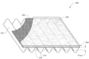
도 1은 본원에 개시하는 기술과 일치하는 예시적인 필터 매체(100)를 도시한다. 필터 매체(100)는 필터 재료(110)의 하류층 및 섬유들(120)의 상류층을 갖는다. 필터 재료(110)의 하류층은 주름형 또는 세로 홈(flute)이 있는 구성으로 되어 있다. 섬유들(120)의 상류층은 일반적으로 주름형이 아니다(세로 홈이 없다). 예시적인 필터 매체(100) 및 대응하는 구성요소는, 명시적으로 모순되는 경우를 제외하고는 본원에 기재된 다른 예와 동일한 구성요소, 파라미터, 및 특성을 가질 수 있다.1 depicts an
필터 재료(110)의 하류층은 다양한 유형의 필터 재료 및 필터 재료 유형들의 조합일 수 있다. 일부 실시예에서, 필터 재료(110)의 하류층은 셀룰로오스 섬유들을 함유한다. 일부 실시예에서, 필터 재료(110)의 하류층은 합성 섬유들을 포함한다. 일부 실시예에서, 필터 재료(110)의 하류층은 중합체 섬유들을 함유한다. 필터 재료(110)의 하류층은 다양한 실시예에서 필터 재료의 다중 층을 포함할 수 있다. 다양한 실시예에서, 필터 재료(110)의 하류층은 자기 지지형이며, 이는, 물결화가 진행될 때, 필터 재료(110)의 하류층이 중력의 힘 및/또는 필터링 작업 동안 겪게 되는 힘을 받는 상태에서 물결형 구성을 유지할 수 있게 하는 강성을 나타낸다는 것을 의미한다. 일부 실시예에서, 필터 재료(110)의 하류층에 의해 형성되는 주름은, 자기 지지형으로 되도록 필터 재료(110)의 강성을 증가시킨다. 일례로, 필터 재료(110)의 강성은 걸리(Gurley) 강성을 사용하여 정량화될 수 있으며, 이러한 걸리 강성은 일부 경우에 적어도 2000 mg일 수 있다. 그러나, 다른 일부의 경우에는, 걸리 강성이 2000 mg 미만일 수 있다. 걸리 강성은, 산업 표준 TAPPI #T543 OM-16(2016) 및 ASTM D6125-97(2007)을 충족하는 걸리 강성 테스터를 사용하여 계산될 수 있다.The downstream layer of
필터 재료(110)의 하류층에 혼입된 섬유들의 크기는 섬유 유형에 의존할 수 있다. 일반적으로, 필터 재료(110)의 하류층에 혼입된 섬유들은 섬유 직경들의 범위를 갖는다. 필터 재료(110)의 하류층에 혼입된 섬유들은 약 4 ㎛ 내지 30 ㎛ 범위의 평균 섬유 직경을 가질 수 있다. 평균 섬유 직경은, 미국 콜로라도 골든에 소재하는 ResAlta Research Technologies의 Scandium M 소프트웨어를 사용하여 결정된다. 필터 매체의 일부는, 30개의 샘플 섬유와 대표 직경이 사용자에 의해 식별되고 소프트웨어에 기록될 수 있도록 주사 전자 현미경(SEM)을 통해 관찰된다. 소프트웨어는, 각 섬유의 단면을 측정하고, 선택한 모든 섬유의 평균, 최소, 최대, 및 표준 편차를 계산한다. 일부 실시예에서, 필터 재료의 하류층의 섬유들은 적어도 20 ㎛의 평균 섬유 직경을 갖는다. 필터 재료(110)의 하류층에 혼입된 섬유들은, 예컨대, 4 ㎛ 내지 20 ㎛, 10 ㎛ 내지 15 ㎛, 15 ㎛ 내지 20 ㎛, 20 ㎛ 내지 25 ㎛, 또는 10 ㎛ 내지 30 ㎛의 평균 섬유 직경을 가질 수 있다.The size of the fibers incorporated in the downstream layer of
필터 재료(110)의 하류층은 적어도 10%의 포집 효율을 가지며, 포집 효율은, 20 ft./min(6.1 meters/min)에서의 0.78 ㎛ 단분산 폴리스티렌 라텍스 구형 입자를 이용한 ASTM 표준 F1215-89에 따라 (주름형일 수 있거나 주름형이 아닐 수 있는) 비물결형 평평 시트에 대해 결정된다. 일부 실시예에서, 필터 재료(110)의 하류층은 적어도 20%의 포집 효율을 갖는다. 일부 실시예에서, 필터 재료(110)의 하류층은 적어도 90%의 포집 효율을 갖는다. 일부 실시예에서, 필터 재료(110)의 하류층은 10% 내지 80%, 20% 내지 40%, 60% 내지 99%, 또는 30% 내지 70%의 포집 효율을 갖는다.The downstream layer of
일례로, 필터 재료(110)의 하류층은 중량 기준으로 약 80%의 셀룰로오스 섬유들을 갖는다. 일부 예에서, 필터 재료(110)의 하류층은 약 20중량%의 결합제를 갖는다. 결합제는, 예를 들어, 라텍스 또는 아크릴일 수 있다. 필터 재료(110)의 하류층의 평량은 가변적이나, 일례로, 평량은 96 g/m2이다.In one example, the downstream layer of
필터 재료(110)의 하류층의 주름(116)은, 필터 매체(100)의 길이(L)에 걸쳐 교번하는 복수의 피크(112)와 밸리(114)를 정의한다. 본원에서 사용되는 바와 같은 "피크"와 "밸리"는, 공간에서의 주름의 특정 방향을 나타내는 것이 아니며, 오히려, "피크"와 "밸리"라는 용어는 본원에서 반대 방향으로 돌출되는 주름들을 설명하도록 사용되는 것이다. 본원에서 설명되는 주름은 일반적으로 사인파형이지만, 주름은 다른 형상을 가질 수 있다. 일부 실시예에서, 주름은 세로 홈의 길이 아래로 연장되는 하나 이상의 접힘 선과 같은 세로 홈의 곡률에 있어서 불연속부를 혼입할 수 있다. 또한, 피크와 밸리는 일반적으로 동일하고 반대이지만, 일부 실시예에서 피크는 밸리와는 다른 크기를 가질 수 있다.The
필터 재료(110)의 하류층의 주름은 0.23 mm 초과의 평균 주름 깊이를 가질 수 있다. 필터 재료(110)의 하류층의 주름은 일반적으로 4.0 mm 미만의 평균 주름 깊이를 갖는다. 다양한 실시예에서, 필터 재료(110)는 2.0 mm 미만의 평균 주름 깊이를 갖는다. 필터 재료(110)의 하류층의 주름은 1.5 mm 미만의 평균 주름 깊이를 가질 수 있다. 일부 실시예에서, 필터 재료(110)의 하류층의 주름은 0.23 mm 내지 0.65 mm의 평균 주름 깊이를 갖는다. 주름 깊이(D)는 필터 재료(110)의 피크(112)와 인접하는 밸리(114) 사이의 z-방향 거리로서 정의되며, 여기서 z-방향은 필터 재료(110)의 길이(L) 및 폭(W)에 수직이다. 평균 주름 깊이는 필터 재료(110)에 걸쳐 측정된 주름 깊이들의 샘플의 평균이며, 이는 필터 재료(110)의 총 주름 깊이의 적어도 5%, 10%, 15%, 또는 20%의 샘플 크기를 가질 수 있다.The pleats of the downstream layer of
섬유들(120)의 상류층은 일반적으로 필터 재료(110)의 하류층의 피크(112)를 가로질러 연장된다. 다양한 실시예에서, 섬유들(120)의 상류층은 필터 재료(110)의 하류층에 접착되지 않고 이러한 하류층으로부터 결합 해제된 상태로 유지된다. 대안으로, 섬유들(120)의 상류층은 일부 실시예에서 접착제에 의해 피크(112)에 결합될 수 있고, 다른 실시예에서, 섬유들(120)의 상류층 내의 섬유들의 적어도 일부를 형성하는 재료는 피크(112)를 형성하는 필터 재료(110)의 하류층에 자기 접착된다. 섬유들(120)의 상류층은, 예를 들어, 미경화(또는 습윤) 섬유들이 필터 재료(110)의 하류층에 걸쳐 증착되고 경화(또는 건조)되도록 방치될 때 자기 접착될 수 있다. 일부 실시예에서, 섬유들(120)의 상류층은 느슨한 섬유들이며, 이는 섬유들(120)의 상류층에 있는 섬유들이 서로 실질적으로 결합되지 않음을 의미한다. 이러한 일부 실시예에서, 섬유들(120)의 상류층에 있는 섬유들은 서로 전혀 결합되지 않는다. 일부 실시예에서, 섬유들(120)의 상류층은 스크림 재료일 수 있다. 스크림 재료는, 예를 들어, 직조된 섬유, 부직 섬유, 또는 편직 섬유일 수 있다. 일부 실시예에서, 섬유들(120)의 상류층은, 예를 들어, 섬유들의 제1 층을 스크림 재료와 결합하는 하나 이상의 층을 가질 수 있다.The upstream layer of
섬유들(120)의 상류층은 일반적으로 필터 재료(110)의 하류층의 상당 부분에 걸쳐 연장된다. 일부 실시예에서, 섬유들(120)의 상류층은 필터 재료(110)의 전체 하류층에 걸쳐 연장된다. 필터 재료(110)의 하류층은 주름지는 반면, 섬유들(120)의 상류층은 비주름형이며 대략 평면이다. 그러나, 섬유들(120)의 상류층은 완전하게 평면은 아닌데, 그 이유는 필터 재료(110)의 하류층의 인접한 피크들(112) 사이에 위치하는 섬유들(120)의 상류층의 부분이 중력에 반응하여 처질 수 있기 때문이다. 또한, 섬유들(120)의 상류층에 있는 일부 섬유는, 필터 매체(100)의 길이(L) 및 폭(W) 방향에 의해 정의되는 평면으로부터 외측으로 연장될 수 있고, 섬유들(120)의 상류층에 의해 정의되는 대략적 평면을 넘어 연장될 수 있다. 일반적으로 말해서, 섬유들(120)의 상류층은 필터 재료(110)의 하류층의 밸리(114)로부터 실질적으로 존재하지 않는다.The upstream layer of
필터 재료(110)의 하류층에 의해 정의되는 주름(116)는, 필터 재료(110)의 하류층과 섬유들(120)의 상류층 사이의 공극 공간을 정의하는 일종의 이격 구조이다. 특히, 주름(116)는 이격 구조를 정의한다. 다양한 실시예에서, 층들 사이의 이러한 공극 공간은, 필터 재료(110)의 하류층과 섬유들(120)의 상류층 사이에 정의된 평균 공극 거리(Dmean)에 따라 특징지어질 수 있다. 현재 도시된 예에서, 필터 재료(110)의 하류층과 섬유들(120)의 상류층 사이에 폭 방향(W)으로 정의된 공극 거리는 대략 일정하다. 이와 같이, 평균 공극 거리(Dmean)는, 길이(L)를 따라 필터 재료(110)의 하류층과 섬유들(120)의 상류층 사이의 (길이(L) 및 z-방향으로 연장되는 평면에서의) 총 단면적(A)을 결정한 후 단면적(A)을 필터 매체(100)의 길이(L)로 제산함으로써, 계산될 수 있다.The
일부 실시예에서, 필터 재료(110)의 하류층과 섬유들(120)의 상류층 사이의 평균 공극 거리(Dmean)는 0.11 mm 초과이다. 필터 재료(110)의 하류층과 섬유들(120)의 상류층 사이의 평균 공극 거리(Dmean)는 대략 2.0 mm 미만이다. 다양한 실시예에서, 필터 재료(110)의 하류층과 섬유들(120)의 상류층 사이의 평균 공극 거리(Dmean)는 1.0 mm 미만일 수 있다. 필터 재료(110)의 하류층과 섬유들(120)의 상류층 사이의 평균 공극 거리(Dmean)는 0.7 mm 미만일 수 있다. In some embodiments, the average pore distance (D mean ) between the downstream layer of
본 개시 내용을 위해, 필터 재료(110)의 하류층과 섬유들(120)의 상류층 사이의 총 단면적과 평균 공극 거리(Dmean)는, 섬유들(120)의 상류층에 있는 섬유들이 필터 재료(110)의 하류층의 밸리(114)를 향하여 (층들(110, 120) 사이의 공극 공간 내로) 피크(112)를 지나 연장되지 않는다고 가정하는 이론적 계산이다. 다시 말해서, 계산은 섬유들(120)의 상류층의 하류측이 완벽하게 평면인 것으로 가정한다. For purposes of this disclosure, the total cross-sectional area and the mean void distance (D mean ) between the downstream layer of
일반적으로, 섬유들(120)의 상류층의 고형도는 필터 재료(110)의 하류층의 고형도보다 작다. 본원에서 사용되는 바와 같은 "고형도"는, 특정 압력에서 측정되는 두께에서 (기체 및 공간보다는) 고체 재료로 구성된 층의 전체 부피의 백분율이다. 고형도는 다음에 따르는 등식에 의해 계산된다.In general, the solidity of the upstream layer of
![]()
![]()
여기서, (필터 재료(110)의 층 또는 섬유들(120)의 층과 같은) 재료의 밀도는, (섬유들(120)의 층의 섬유 밀도와 같이) 재료를 형성하는 구성 성분들의 밀도에 의해 제산된다. 재료의 밀도는 다음 등식에 의해 계산될 수 있다.Here, the density of a material (such as a layer of
![]()
![]()
여기서, 두께는 (섬유들(120)의 층과 같은) 재료의 두께이다. 본 개시내용을 위해, 재료의 두께는, 재료에 대하여 0.07 psi를 가하며 직경이 1.129"(1제곱인치)인 노로드 캘리퍼(no-load caliper)(특히, 미국 매사추세츠주 프레이밍햄에 소재하는 B.C. Ames Incorporated에서 제조한 Ames Thickness Tester)를 이용하여 결정된다. 이와 같이, 본원에서 개시되는 바와 같은 재료의 고형도는, 두께 측정을 달성하기 위해 재료에 가해지는 0.07 psi에 기초하여 계산되는 것으로 이해된다.Here, the thickness is the thickness of the material (such as the layer of fibers 120 ). For purposes of this disclosure, the thickness of the material is a no-load caliper having a diameter of 1.129" (1 square inch) applying 0.07 psi to the material (particularly BC Ames, Framingham, Massachusetts, USA). Ames Thickness Tester manufactured by Incorporated) As such, it is understood that the solidity of a material as disclosed herein is calculated based on 0.07 psi applied to the material to achieve a thickness measurement.
섬유들(120)의 상류층은 일반적으로 10% 미만의 고형도를 갖는다. 일부 실시예에서, 섬유들(120)의 상류층은 8% 미만의 고형도를 갖는다. 일부 실시예에서, 섬유들(120)의 상류층은 2% 내지 9%의 고형도를 갖는다.The upstream layer of
섬유들(120)의 상류층은 일반적으로 필터 재료(110)의 하류층의 평량보다 작은 평량을 갖는다. 섬유들(120)의 상류층은 1 g/m2 내지 45 g/m2 또는 15 g/m2 내지 40 g/m2의 평량을 가질 수 있다. 일부 실시예에서, 섬유들의 상류층의 평량은 약 21 g/m2 또는 30 g/m2이다. 일부 실시예에서, 섬유들(120)의 상류층의 평량은 2 g/m2 내지 10 g/m2의 평량 범위를 가질 수 있다.The upstream layer of
다양한 실시예에서, 섬유들(120)의 상류층은 10 ㎛ 초과의 평균 섬유 직경을 갖는 섬유들을 함유한다. 다양한 실시예에서, 섬유들(120)의 상류층은 적어도 15 ㎛의 평균 섬유 직경을 갖는 섬유들을 함유한다. 일부 실시예에서, 섬유들(120)의 상류층은, 표준 편차가 2이면서 적어도 20 ㎛의 평균 섬유 직경을 갖는 섬유들을 함유한다. 섬유들(120)의 상류층은 1.0 mm 미만의 평균 섬유 직경을 갖는 섬유들을 함유한다. 섬유들(120)의 상류층은 일반적으로 0.5 mm 미만의 평균 섬유 직경을 갖는 섬유들을 함유한다. 섬유들(120)의 상류층은 0.1 mm 미만의 평균 섬유 직경을 갖는 섬유들을 함유할 수 있다. 일부 실시예에서, 섬유들(120)의 상류층은 필터 재료(110)의 하류층에 함유된 섬유들보다 거친 섬유들을 함유할 수 있다.In various embodiments, the upstream layer of
섬유들(120)의 상류층은 다양한 유형의 섬유 및 섬유들의 조합을 함유할 수 있다. 섬유들(120)의 상류층에 있는 섬유는, 멜트블로운 또는 스펀본드 섬유와 같이 실질적으로 연속적일 수 있고, 불연속적일 수 있고, 또는 이들의 조합일 수 있다. 일부 실시예에서, 섬유들(120)의 상류층은 중합체 섬유들이다. 일부 실시예에서, 섬유들(120)의 상류층에 있는 복수의 섬유는 예시적인 크림프(122)와 같이 권축된다. 섬유의 크림프(122)는 접힘 또는 구김과 유사한 섬유 곡률의 불연속부이다. 이러한 권축된 섬유들은 섬유들(120)의 상류층에 로프트(loft)를 추가할 수 있으며, 이는, 예를 들어, 섬유들(120)의 상류층의 두께를 증가시키거나 동일한 두께의 섬유들(120)의 상류층의 평량을 감소시킴으로써 상대적 고형도를 감소시킬 수 있다.The upstream layer of
다양한 실시예에서, 섬유들(120)의 상류층은 자기 지지형이 아니며, 이는 섬유들(120)의 상류층이 강성을 나타내지 않고 중력 하에서 물결형 구성을 유지하기 위해 물결화될 수 없음을 의미한다. 섬유들(120)의 상류층은 필터 재료(110)의 하류층과 직접 접촉할 수 있다. 섬유들(120)의 상류층은 필터 재료(110)의 하류층에 직접 결합될 수 있으며, 이는 (접착제가 사용되는 경우) 접착제를 제외하고는 섬유들(120)의 상류층과 필터 재료(110)의 하류층 사이에 개재 재료가 없음을 의미한다.In various embodiments, the upstream layer of
본원의 필터 매체(100)는 다양한 다른 구성 층을 혼입할 수 있지만, 다양한 실시예에서, 섬유들(120)의 상류층은 필터 매체의 단부층(최상류층)이다. 이와 같이, 섬유들(120)의 상류층은 필터 매체(100)에 진입하는 먼지에 대한 노출을 최대화하도록 위치한다.While the
위에서 논의된 바와 같이, 일부 실시예에서, 섬유들의 상류층은 도 2에 도시된 스크림 재료 상에 배치된 섬유들의 제1 층과 같은 다중 층을 가질 수 있다. 도 1을 참조하여 전술한 실시예와 유사하게, 현재 설명되는 필터 매체(200)는 필터 재료(210)의 하류층 및 섬유들(220)의 상류층을 갖는다. 필터 재료(210)의 하류층은, 주름형 구성이고, 자신의 길이를 따라 교번하는 복수의 피크(212)와 밸리(214)를 정의한다. 섬유들(220)의 상류층은 필터 재료(210)의 하류층의 피크(212)를 가로질러 연장된다. 섬유들(220)의 상류층은 일반적으로 주름형이 아니며 대략 평면인 것으로 간주될 수 있다. 예시적인 필터 매체(200) 및 대응하는 구성요소는, 명시적으로 모순되는 경우를 제외하고는 본원에서 설명되는 기재된 다른 예와 동일한 구성요소, 파라미터, 및 특성을 가질 수 있다.As discussed above, in some embodiments, the upstream layer of fibers may have multiple layers, such as the first layer of fibers disposed on the scrim material shown in FIG. 2 . Similar to the embodiment described above with reference to FIG. 1 , the presently described filter medium 200 has a downstream layer of
도 1을 참조하여 설명되는 실시예와는 달리, 현재 예에서, 섬유들(220)의 상류층은 섬유들(222)의 제1 층 및 지지층(224)을 갖는다. 지지층(224)은 필터 재료(210)의 하류층과 섬유들(222)의 제1 층 사이에 배치된다. 지지층(224)은 필터 재료(210)의 하류층의 주름에 의해 정의된 피크(212)와 접촉한다. 지지층(224)은, 접착제로 또는 대체 방안을 통해 피크(212)에 결합될 수 있고, 일부 실시예에서, 지지층(224)과 필터 재료(210)의 하류층은 결합 해제된다. 일부 예에서, 지지층(224)은 일반적으로 자기 지지형이며, 이는 지지층(224)이 지지층(224)이 물결화될 수 있는 강성을 갖는 반면, 다른 실시예에서는 지지층(224)이 자기 지지형이 아님을 의미한다. 지지층(224)은 다양한 재료 및 재료들의 조합일 수 있고, 일부 실시예에서, 지지층(224)은 와이어 또는 중합체 메시와 같은 메시이다. 일반적으로, 지지층(224) 자체는 0.78 ㎛ 입자를 필터링할 때 필터링 효율 또는 압력 강하를 나타내지 않는다.Unlike the embodiment described with reference to FIG. 1 , in the present example, the upstream layer of
도 3은, ISO 미세 테스트 먼지를 사용하여 3개의 상이한 예시적인 필터 매체에 대해 집진된 먼지 및 차압을 측정하는 테스트 결과를 도시한다. 제1 비교예(310), 제2 비교예(320), 및 제3 비교예(330) 각각은, 셀룰로오스 매체의 상대적 하류 시트와 맞닿는 상대적 상류 스크림 층을 갖는 비주름형 필터 재료의 하류층을 혼입한다. 비주름형 필터 재료의 하류층 각각은 동일한 조성 및 필터링 특성을 갖는다.3 shows the test results of measuring the dust collected and the differential pressure for three different exemplary filter media using the ISO fine test dust. Comparative Example 1 310, Comparative Example 2 320, and Comparative Example 3 330 each incorporate a downstream layer of a pleated filter material having a relatively upstream scrim layer abutting a relatively downstream sheet of cellulosic media. do. Each of the downstream layers of pleated filter material has the same composition and filtering properties.
제1 비교예(310)는 필터 재료 단독의 하류층이다. 제2 비교예(320) 및 제3 비교예(330)는 각각 필터 재료의 하류층과 접하는 섬유들의 상류층을 혼입한다. 섬유들의 상류층 각각은 스크림 층의 상류 표면 상에 습식-적층된 폴리에틸렌-폴리프로필렌(PE/PP) 이성분 섬유들을 함유한다. 제2 비교예(320)에 사용된 섬유들의 제1 상류층은 12%의 고형도, 21.5 g/m2의 평량, 및 30.45 ㎛의 평균 섬유 직경을 갖는다. 제3 비교예(330)에서 섬유들의 제2 상류층은 3%의 고형도, 21.5 g/m2의 평량, 및 27 ㎛의 평균 섬유 직경을 갖는다. 각각의 비교예를 테스트하기 위해, (제2 및 제3 비교예에 대한 섬유들의 상류층을 갖는) 스크림의 둘레 및 셀룰로오스 매체의 시트를 테스트 장비에 의해 함께 클램핑한다. 비교예(310, 320, 330) 각각을 2회 테스트하였다.The first comparative example 310 is a downstream layer of filter material alone. Comparative Example 2 320 and Comparative Example 330 each incorporate an upstream layer of fibers adjoining a downstream layer of filter material. Each upstream layer of fibers contains polyethylene-polypropylene (PE/PP) bicomponent fibers wet-laid onto the upstream surface of the scrim layer. The first upstream layer of fibers used in Comparative Example 2 320 had a solidity of 12%, a basis weight of 21.5 g/m 2 , and an average fiber diameter of 30.45 μm. The second upstream layer of fibers in Comparative Example 3 330 has a solidity of 3%, a basis weight of 21.5 g/m 2 , and an average fiber diameter of 27 μm. To test each comparative example, the perimeter of the scrim (with the upstream layer of fibers for the second and third comparative examples) and a sheet of cellulosic media are clamped together by means of a test rig. Each of Comparative Examples 310, 320, and 330 was tested twice.
도 3의 그래프는, 제3 비교예(330)가 약 50 g/m2 초과의 먼지를 적재한 후 제1 비교예(310) 및 제2 비교예(320)보다 필터 매체에 걸쳐 더 낮은 차압을 갖는다는 점을 입증한다. 데이터는 12%의 고형도를 갖는 섬유들의 상류층의 존재가 필터 매체의 수명에 주목할만한 영향을 미치지 않지만, 3%의 고형도를 갖는 섬유들의 상류층의 존재는 필터 매체의 수명에 현저한 영향을 미친다는 점을 시사한다. 현재 기술과 일치하는 다양한 실시예에서, 섬유들의 상류층은 10% 미만의 고형도를 갖는다.The graph of FIG. 3 shows that Comparative Example 3 330 has a lower differential pressure across the filter media than Comparative Example 1 310 and Comparative Example 2 320 after loading greater than about 50 g/m 2 of dust. prove that it has The data show that the presence of an upstream layer of fibers with a solids of 12% has no appreciable effect on the lifetime of the filter media, whereas the presence of an upstream layer of fibers with a solids of 3% has a significant effect on the lifetime of the filter media. points to the point In various embodiments consistent with the current art, the upstream layer of fibers has a solidity of less than 10%.
도 4는, ISO 미세 테스트 먼지를 사용하여 3개의 상이한 예시적인 필터 매체에 대해 집진된 먼지 및 차압을 측정하는 추가 테스트 결과를 도시한다. 제4 비교예(410), 제5 비교예(420), 및 제6 비교예(430) 각각은 (셀룰로오스 매체의 상대적 하류 시트와 맞닿는 상대적 상류 스크림 층을 갖는) 도 3을 참조하여 전술한 비주름형 필터 재료의 하류층을 사용한다. 제4 비교예(410)는 필터 재료 단독의 하류층이며, 여기서 스크림 층 및 셀룰로오스 매체는 테스트를 위해 이들의 둘레 주위에서 함께 클램핑된다. 제5 비교예(420)와 제6 비교예 각각은 스크림 층 상에 습식-적층된 섬유들의 상류층을 혼입한다. 제5 비교예(420)의 섬유들의 제3 상류층은, 21.5 g/m2의 평량, 6%의 고형도를 갖는 폴리에틸렌 테레프탈레이트(co-PET) 이성분 섬유들, 및 15 ㎛의 평균 섬유 직경을 갖는 섬유들이다. 제6 비교예(430)의 섬유들의 제4 상류층은, 21.5 g/m2의 평량, 3%의 고형도, 및 30 ㎛의 평균 섬유 직경을 갖는 섬유들을 갖는 PE/PP 이성분 섬유들이다. 테스트 장비는, 테스트를 위해 각각의 둘레 주위로 셀룰로오스 매체의 시트에 대하여 섬유들의 상류층을 갖는 스크림을 클램핑한다.Figure 4 shows the results of a further test using the ISO fine test dust to measure the collected dust and differential pressure for three different exemplary filter media. Comparative Example 4 410, Comparative Example 5 420, and Comparative Example 6 430 each have the ratios described above with reference to FIG. 3 (with a relatively upstream scrim layer abutting a relatively downstream sheet of cellulosic medium). Use a downstream layer of pleated filter material. A fourth comparative example 410 is a downstream layer of filter material alone, wherein the scrim layer and cellulosic media are clamped together around their perimeter for testing. Comparative Examples 5 420 and 6 each incorporate an upstream layer of fibers wet-laid onto the scrim layer. The third upstream layer of fibers of Comparative Example 5 420 was polyethylene terephthalate (co-PET) bicomponent fibers having a basis weight of 21.5 g/m 2 , a solidity of 6%, and an average fiber diameter of 15 μm. fibers with The fourth upstream layer of fibers of Comparative Example 6 430 is PE/PP bicomponent fibers having fibers having a basis weight of 21.5 g/m 2 , a solids content of 3%, and an average fiber diameter of 30 μm. Test equipment, and clamps the scrim with the upper class of the fibers with respect to the sheet of each of the two rail cellulose medium around to test.
도 4의 그래프는, 제6 비교예(430)가 적어도 약 50 g/m2 초과의 먼지를 적재한 후 제4 비교예(410) 및 제5 비교예(420)보다 낮은 차압을 갖는다는 점을 입증한다. 데이터는, 15 ㎛의 평균 섬유 직경을 갖는 섬유들의 상류층의 존재가 필터 매체의 수명에 유리하게 영향을 미치지 않지만, 30 ㎛의 평균 섬유 직경을 갖는 섬유들의 상류층의 존재는 필터 매체의 수명에 유리하게 영향을 미치는 것으로 보인다는 점을 시사한다. 일부 실시예에서, 섬유들의 상류층은 15 ㎛ 초과의 평균 섬유 직경을 갖는다. 현재 기술과 일치하는 다양한 실시예에서, 섬유들의 상류층은 2의 표준 편차와 함께 적어도 20 ㎛의 평균 섬유 직경을 갖는다.The graph of FIG. 4 shows that Comparative Example 6 430 has a lower differential pressure than Comparative Example 4 410 and Comparative Example 5 420 after loading of at least about 50 g/m 2 of dust. prove the The data show that the presence of an upstream layer of fibers with an average fiber diameter of 15 μm does not favorably affect the lifetime of the filter media, whereas the presence of an upstream layer of fibers with an average fiber diameter of 30 μm favorably affects the lifetime of the filter media. suggest that it appears to have an impact. In some embodiments, the upstream layer of fibers has an average fiber diameter greater than 15 μm. In various embodiments consistent with the present art, the upstream layer of fibers has an average fiber diameter of at least 20 μm with a standard deviation of two.
전술한 바와 같이, ISO 미세 테스트 먼지를, 먼지 입자가 특정 크기 범위와 분포를 갖는 도 4에 연관된 테스트에서 사용하였다. 필터링될 입자가 ISO 미세 테스트 먼지와는 다른 크기 범위 및/또는 크기 분포를 갖는 다른 일부 구현예에서, 섬유들의 상류층에 있는 섬유들의 상이한 평균 섬유 직경은 섬유들의 상류층이 없는 매체에 비해 필터 매체 수명이 개선된다는 점을 입증할 수 있다. 일부 이러한 구현예에서, 섬유들의 상류층은 10 ㎛, 12 ㎛, 14 ㎛, 또는 15 ㎛의 평균 섬유 직경을 가질 수 있다. 일부 이러한 구현예에서, 섬유들의 상류층은 적어도 10 ㎛, 12 ㎛, 14 ㎛, 또는 15 ㎛의 평균 섬유 직경을 가질 수 있다.As described above, ISO fine test dust was used in the test associated with FIG. 4 where the dust particles had a specific size range and distribution. In some other embodiments where the particles to be filtered have a different size range and/or size distribution than the ISO fine test dust, the different average fiber diameters of the fibers in the upstream layer of fibers result in a longer filter media life compared to media without the upstream layer of fibers. improvement can be demonstrated. In some such embodiments, the upstream layer of fibers can have an average fiber diameter of 10 μm, 12 μm, 14 μm, or 15 μm. In some such embodiments, the upstream layer of fibers can have an average fiber diameter of at least 10 μm, 12 μm, 14 μm, or 15 μm.
도 5는, ISO 미세 테스트 먼지를 사용하여 4개의 상이한 예시적인 필터 매체에 대해 집진된 먼지 및 차압을 측정하는 추가 테스트 결과를 도시한다. 비교예들의 각각은 셀룰로오스 매체의 시트인 필터 재료의 하류층을 혼입한다. 셀룰로오스 매체의 각 시트는, 중량 기준으로 약 80%의 셀룰로오스 섬유와 20%의 결합제를 가지며, 평균 섬유 직경은 15.8 ㎛이다.5 shows the results of a further test using ISO fine test dust to measure the collected dust and differential pressure for four different exemplary filter media. Each of the comparative examples incorporates a downstream layer of filter material that is a sheet of cellulosic media. Each sheet of cellulosic media had about 80% cellulosic fibers and 20% binder by weight, and had an average fiber diameter of 15.8 μm.
제7 비교예(510)와 제8 비교예(520) 각각은, 평량이 약 96.1g/m2이고 포집 효율이 25%인 비주름형 셀룰로오스 매체의 시트를 갖는다. 제7 비교예(510)는 셀룰로오스 매체 단독의 시트이다. 제8 비교예(520)는, 30g/m2의 평량, 7%의 고형도를 갖는 폴리에틸렌 테레프탈레이트/폴리프로필렌(PET/PP) 이성분 섬유로 구축된 스크림 층인 섬유들의 상류층을 혼입하며, 38 ㎛의 평균 섬유 직경을 갖는 섬유들을 함유한다.Each of the seventh comparative example 510 and the eighth comparative example 520 had a sheet of non-corrugated cellulosic medium having a basis weight of about 96.1 g/m 2 and a collecting efficiency of 25%. The seventh comparative example 510 is a sheet of cellulosic medium alone. The eighth comparative example 520 incorporates an upstream layer of fibers, a scrim layer constructed of polyethylene terephthalate/polypropylene (PET/PP) bicomponent fibers having a basis weight of 30 g/m 2 and a solidity of 7%, 38 It contains fibers having an average fiber diameter of μm.
제9 비교예(530)와 제10 비교예(540)의 셀룰로오스 매체 시트 각각은 평량이 114.5g/m2이고 포집 효율이 33%이다. 제9 비교예(530) 및 제10 비교예(540)의 셀룰로오스 매체 시트 각각은 0.58 mm의 평균 주름 깊이를 정의하도록 주름진다. 제9 비교예(530)는 주름형 구성의 셀룰로오스 매체 단독 시트이다. 제10 비교예(540)는 주름형 필터 재료의 상류측에 맞닿는 섬유들의 상류층을 추가로 갖는다. 제10 비교예(540)의 섬유들의 상류층은 제8 비교예(520)의 섬유들의 상류층과 동일하다. 이와 같이, 제10 비교예(540)의 섬유들의 층은, 30 g/m2의 평량, 7%의 고형도를 갖고, 38 ㎛의 평균 섬유 직경을 갖는 섬유들을 함유한다.Each of the cellulose media sheets of Comparative Example 9 530 and Comparative Example 10 540 had a basis weight of 114.5 g/m 2 and a collection efficiency of 33%. Each of the cellulosic media sheets of Comparative Example 9 530 and Comparative Example 10 540 were corrugated to define an average wrinkle depth of 0.58 mm. The ninth comparative example 530 is a single sheet of cellulosic medium in a pleated configuration. A tenth comparative example 540 further has an upstream layer of fibers against the upstream side of the pleated filter material. The upstream layer of fibers of Comparative Example 10 540 is the same as the upstream layer of fibers of Comparative Example 8 520 . As such, the layer of fibers of Comparative Example 10 540 contains fibers having a basis weight of 30 g/m 2 , a solidity of 7%, and an average fiber diameter of 38 μm.
테스트를 위해, 각 예의 필터 매체는 해당 필터 매체 각각의 둘레 주위로 클램핑된다. 예가 섬유들의 상류층을 혼입하는 경우, 섬유들의 상류층이 셀룰로오스 매체의 주름형 시트의 상류측과 맞닿도록, 섬유들의 상류층과 셀룰로오스 매체 시트는 테스트를 위해 자신들의 둘레 주위로 함께 클램핑된다.For testing, the filter media of each example is clamped around the perimeter of each of the respective filter media. If the example incorporates an upstream layer of fibers, the upstream layer of fibers and the cellulosic media sheet are clamped together around their perimeter for testing, such that the upstream layer of fibers abuts the upstream side of the pleated sheet of cellulosic media.
도 5는, (제10 비교예(540)의) 주름형 매체 하류층과 비주름형 섬유들의 상류층의 조합이 약 100 g/m2 초과의 먼지를 적재한 후 더 낮은 차압을 갖고, 이는 필터 매체의 수명에 유리하게 영향을 미친다는 점을 입증하는 것으로 보인다.5 shows that the combination of a pleated media downstream layer (of Comparative Example 10 540) and an upstream layer of non-corrugated fibers has a lower differential pressure after loading greater than about 100 g/m 2 dust, which is the filter media appears to prove that it favorably affects the lifespan of
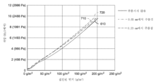
도 6은 6개의 상이한 예시적인 필터 매체에 대해 집진된 먼지 및 차압을 다시 측정하는 테스트 결과를 도시한다. 각각의 예시적인 필터 매체는, 전술한 제7 비교예 및 제8 비교예와 일치하는 셀룰로오스 매체의 시트인 필터 재료의 하류층을 갖는다. 제11 비교예(610)는 셀룰로오스 매체 단독의 비주름형 시트이다. 제12 비교예(620)는 섬유들의 상류층과 맞닿는 셀룰로오스 매체의 비주름형 시트이다. 제13 비교예(630), 제14 비교예(640), 제15 비교예(650), 및 제16 비교예(660) 각각은 섬유들의 상류층과 맞닿는 셀룰로오스 매체의 주름형 하류 시트이다. 도 6의 관련 비교예 각각에서 섬유들의 상류층은 전술한 제10 비교예(540)의 섬유들의 층과 동일하다.Fig. 6 shows the test results of measuring the dust collected and the differential pressure again for six different exemplary filter media. Each exemplary filter media has a downstream layer of filter material that is a sheet of cellulosic media consistent with Comparative Examples 7 and 8 described above. The eleventh comparative example 610 is a non-corrugated sheet of cellulosic medium alone. A twelfth comparative example 620 is a non-corrugated sheet of cellulosic media abutting an upstream layer of fibers. Comparative Example 13 630 , Comparative Example 14 640 , Comparative Example 15 650 , and Comparative Example 16 660 are each a pleated downstream sheet of cellulosic medium abutting an upstream layer of fibers. The upstream layer of fibers in each of the related comparative examples of FIG. 6 is the same as the layer of fibers of the tenth comparative example 540 described above.
제13 비교예, 제14 비교예, 제15 비교예, 및 제16 비교예는, 평균 주름 깊이가 상이한 주름을 갖는다. 제13 비교예(630)에 의해 정의된 주름의 평균 주름 깊이는 0.23 mm이다. 제14 비교예(640)에 의해 정의된 주름의 평균 주름 깊이는 0.39 mm이다. 제15 비교예(650)에 의해 정의된 주름의 평균 주름 깊이는 0.52 mm이다. 제16 비교예(660)에 의해 정의된 주름의 평균 주름 깊이는 0.65 mm이다.Comparative Example 13, Comparative Example 14, Comparative Example 15, and Comparative Example 16 had wrinkles having different average wrinkle depths. The average wrinkle depth of the wrinkles defined by the thirteenth comparative example 630 is 0.23 mm. The average wrinkle depth of the wrinkles defined by the fourteenth comparative example 640 is 0.39 mm. The average wrinkle depth of the corrugations defined by the fifteenth comparative example 650 is 0.52 mm. The average wrinkle depth of the wrinkles defined by the sixteenth comparative example 660 is 0.65 mm.
데이터는, 섬유들의 상류층을 비주름형 필터 재료의 하류층(제12 비교예(620))에 혼입함으로써 비주름형 필터 재료의 층 단독(제11 비교예(610))에 비해 필터 수명이 현저히 증가함을 반영한다. 또한, 비주름형 섬유들의 상류층을 혼입하는 필터 매체 구조에서, (제13 비교예(630)의) 0.23 mm의 최대 주름 깊이를 갖는 하류 필터 재료는, 각각의 필터 매체 상에 먼지가 적재됨에 따라 주름이 없는 하류 필터 재료와 섬유들의 상류층을 갖는 필터 매체 구조(제12 비교예(620))와 비교해 볼 때, 차압이 매우 유사한 것으로(또는 아주 약간만 감소된 것으로) 보인다.The data show that incorporating an upstream layer of fibers into a downstream layer of pleated filter material (comparative example 12 620) significantly increases filter life compared to a layer of pleated filter material alone (comparative example 11 610). reflect that Also, in the filter media structure incorporating an upstream layer of non-pleated fibers, the downstream filter material having a maximum pleat depth of 0.23 mm (of the 13th comparative example 630) is, as the dust is loaded on each filter media, When compared to a filter media structure having an upstream layer of fibers and a pleated-free downstream filter material (comparative example twelfth 620), the differential pressure appears to be very similar (or only slightly reduced).
주름진 필터 재료의 하류층을 혼입하는 각 비교예(제13 비교예 내지 제16 비교예)는, (제16 비교예의 경우에) 적어도 150 g/m2의 최소 먼지 적재에 있어서 그러나 일부 예에서는 50 g/m2 또는 100 g/m2의 최소 먼지 적재에 있어서 비주름형 하류층을 갖는 비교예(제12 비교예(620))보다 작은 압력 강하를 갖는다.Each comparative example incorporating a downstream layer of pleated filter material (comparative examples 13 to 16) has a minimum dust loading of at least 150 g/m 2 (in the case of comparative example 16) but in some instances 50 g It has a smaller pressure drop than the comparative example (12th comparative example 620) with a non-corrugated downstream layer at a minimum dust loading of /m 2 or 100 g/m 2 .
도 6에 반영된 그 결과는 놀랍다. 제16 비교예(660)는, 약 70 g/m2의 먼지 적재에서 나머지 비교예들의 압력 강하를 초과하는 압력 강하를 갖는 것으로 보인다. (제13 비교예(630)의) 최대 주름 깊이가 0.23 mm인 매체는, 각 필터 매체 상에 먼지가 적재됨에 따라 주름이 없는 하류 필터 재료를 갖는 필터 매체 구조를 비주름형 필터 매체 구조(제12 비교예(620))와 매우 유사하게 기능한다.The results reflected in FIG. 6 are surprising. The sixteenth comparative example 660 appears to have a pressure drop exceeding that of the remaining comparative examples at a dust loading of about 70 g/m 2 . The media with a maximum pleat depth of 0.23 mm (of Comparative Example 13 630) was compared to the filter media structure with the downstream filter material free from pleats as the dust was loaded on each filter medium to the non-corrugated filter medium structure (No. 12 It functions very similarly to Comparative Example 620).
도 6에 반영된 압력 강하 개선이 필터 재료의 하류층의 평균 주름 깊이의 함수인지 여부를 결정하기 위해 테스트를 수행하였다. 도 11은, 상이한 평균 주름 깊이를 갖는 셀룰로오스 매체 단독(각 매체는 섬유들의 상류층을 갖지 않음)의 두 개의 주름형 시트에 비해 (섬유들의 상류층 없이) 셀룰로오스 매체 단독의 비주름형 시트인 도 6의 제11 비교예(610)에 연관된 데이터를 반영한다. 제1 셀룰로오스 매체(710)는 0.65 mm의 평균 주름 깊이를 갖고, 제2 셀룰로오스 매체(720)는 0.23 mm의 평균 주름 깊이를 갖는다. 놀랍게도, 도 11은, 섬유들의 상류층이 없는 경우, 셀룰로오스 매체 만의 평균 주름 깊이로는 매체 상에 먼지가 적재될 때 매체의 차압을 감소시키는 것으로 보이지 않음을 입증하는 것으로 보인다. 실제로, 제1 셀룰로오스 매체(710)와 제2 셀룰로오스 매체(720)의 주름은, 제11 비교예(610)의 비주름형 셀룰로오스 매체에 비해, 매체 상에 먼지가 적재됨에 따라 차압이 약간 증가한 것으로 보인다.A test was performed to determine whether the pressure drop improvement reflected in FIG. 6 was a function of the average pleat depth of the downstream layer of filter material. 11 is an uncorrugated sheet of FIG. 6 of cellulosic media alone (without an upstream layer of fibers) compared to two pleated sheets of cellulosic media alone (each media not having an upstream layer of fibers) having different average wrinkle depths; Data related to the eleventh comparative example 610 is reflected. The first
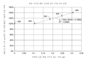
한편, 도 7은, 섬유들의 상류층과 필터 재료의 하류층 사이의 평균 공극 거리에 따른 (도 6을 참조하여 전술한) 제12 비교예(620), 제13 비교예(630), 제14 비교예(640), 제15 비교예(650), 및 제16 비교예(660)의 먼지 보유 능력의 개선을 반영한다. 먼지 보유 용량은, ISO 미세 테스트 먼지를 사용하여 9.6인치-H2O(2388 Pa) 압력 강하, 10.5 ft/min(5.33 cm/sec)의 유속에서 결정된다. 먼지 보유 능력의 개선은, 필터 재료의 하류층이 비주름형이기 때문에 섬유들의 상류층과 필터 재료의 하류층 사이의 평균 공극 거리가 0인 제12 비교예(620)의 먼지 보유 능력에 기초하는 한 백분율이다. 제13 비교예(630), 제14 비교예(640), 제15 비교예(650), 및 제16 비교예(660)의 각각은, 도 1의 Dmean 계산에 대한 논의에서 전술한 바와 같이 계산된 섬유들의 상류층과 필터 재료의 하류층 사이의 평균 공극 거리를 가졌다. Meanwhile, FIG. 7 shows Comparative Example 12 620, Comparative Example 13 630, and Comparative Example 14 (described above with reference to FIG. 6) according to the average pore distance between the upstream layer of fibers and the downstream layer of the filter material. (640), the fifteenth comparative example (650), and the sixteenth comparative example (660) reflect the improvement of the dust holding capacity. Dust holding capacity was determined using ISO fine test dust at a 9.6 inch-H 2 O (2388 Pa) pressure drop, flow rate of 10.5 ft/min (5.33 cm/sec). The improvement of the dust holding capacity is a percentage based on the dust holding capacity of the twelfth comparative example 620, where the average pore distance between the upstream layer of fibers and the downstream layer of the filter material is zero because the downstream layer of the filter material is non-corrugated. . Each of the thirteenth comparative example 630 , the fourteenth comparative example 640 , the fifteenth comparative example 650 , and the sixteenth comparative example 660 , as described above in the discussion of the D mean calculation in FIG. 1 , is Calculated average void distance between the upstream layer of fibers and the downstream layer of filter material.
도 7의 그래프는, 전술한 테스트 파라미터에서, 평균 공극 거리가 0.11 mm 초과일 때 섬유들의 상류층과 필터 재료의 하류층 사이의 평균 공극 거리가 증가함에 따라 먼지 보유 능력이 거의 선형으로 개선된다는 것을 반영한다. 섬유들의 상류층 및/또는 필터 재료의 하류층이 (섬유들의 조합과 섬유들의 교번 유형으로 구축되는 것과 같은) 대체 구성을 가는 경우, 최소 평균 공극 거리는 0.11 mm와 다를 수 있다. "최소 평균 공극 거리"는, 층들 사이의 평균 공극 거리가 약 0인 경우에 비해, 매체의 먼지 보유 용량이 개선을 나타내는 층들 사이의 평균 공극 거리로서 정의된다.The graph of FIG. 7 reflects that, in the test parameters described above, the dust holding capacity improves almost linearly as the average pore distance between the upstream layer of fibers and the downstream layer of filter material increases when the average pore distance is greater than 0.11 mm . If the upstream layer of fibers and/or the downstream layer of filter material has an alternative configuration (such as being built with a combination of fibers and alternating types of fibers), the minimum average pore distance may differ from 0.11 mm. "Minimum average void distance" is defined as the average void distance between layers at which the dust holding capacity of the medium exhibits an improvement compared to the case where the average void distance between the layers is about zero.
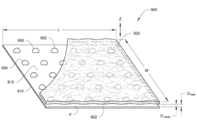
도 8은 본원에 개시하는 기술과 일치하는 다른 예시적인 필터 매체(800)를 도시한다. 도 1과 도 2에 도시된 예시적인 실시예와 유사하게, 필터 매체(800)는 섬유들(820)의 상류층과 맞닿는 필터 재료(810)의 하류층을 갖는다. 섬유들(820)의 상류층은 도 2를 참조하여 전술한 바와 유사한 지지층을 가질 수 있다. 섬유들(820)의 상류층은 필터 재료(810)의 하류층 상의 이격 구조(830)와 직접 접촉할 수 있다. 예시적인 필터 매체(800) 및 대응하는 구성요소는, 명시적으로 모순되는 경우를 제외하고는 본원에 설명되는 다른 예와 동일한 구성요소, 파라미터, 및 특성을 가질 수 있다.8 depicts another
필터 재료(810)의 하류층은 비주름형인 반면, 현재 도시되어 있는 예시적인 필터 매체(800)는, z-방향에 있어서 섬유들(820)의 상류층과 필터 재료(810)의 하류층 사이의 특정 평균 공극 거리(Dmean), 예컨대, 0.11 mm 초과 2.0 mm, 1.0 mm 또는 0.7mm 미만의 평균 공극 거리(Dmean)를 달성하기 위한 다른 구조를 예시한다. 특히, 필터 재료(810)의 하류층 상의 이격 구조(830)는 섬유들(820)의 상류층을 향해 z-방향으로 돌출된다. 현재 예에서, 이격 구조(830)는, 필터 매체(800)의 폭(W)을 따라 연장되고 필터 매체(800)의 길이(L)에 걸쳐 특정 증분으로 이격되는 일련의 이격 세장형 리브(rib)이다.While the downstream layer of
이격 구조(830)는 필터 재료(810) 자체의 하류층에 의해 정의될 수 있다. 예를 들어, 이격 구조(830)는 엠보싱을 통해서와 같이 필터 재료(810)의 하류층을 형상화함으로써 형성될 수 있다. 다른 일부 실시예에서, 이격 구조(830)는, 섬유들(820)의 상류층이 필터 재료(810)의 하류층의 상류측(812) 상에 증착되기 전에, 필터 재료(810)의 하류층의 상류측(812) 또는 섬유들(820)의 상류층의 하류면(822) 상에 증착되는 별도의 구성요소일 수 있다. 예를 들어, 이격 구조(830)는, 미경화 상태로 증착된 후 경화되도록 허용되는 핫 멜트 중합체, 에폭시 수지, 또는 접착제일 수 있다. 다른 일례로, 이격 구조는, 섬유들(820)의 상류층과 필터 재료(810)의 하류층 중 하나 또는 모두에 결합되는 미리 형성된 구조적 구성요소일 수 있다.The
필터 매체(800)의 층들 사이의 간격이 폭(W) 방향을 따라 대략 균일하기 때문에, 섬유들(820)의 상류층과 필터 재료(810)의 하류층 사이의 평균 공극 거리(Dmean)는 길이(L) 방향으로의 평균 공극 거리(Dmean)와 대략 동일할 것이다. 길이(L) 방향으로의 평균 공극 거리(Dmean)는, 도 1을 참조하여 전술한 바와 같이 필터 재료의 하류층과 유사하게, 예를 들어, 층들 사이의 공극의 (길이(L)와 z-방향으로 연장되는 평면에서의) 총 단면적(A)을 계산하고 단면적(A)을 길이(L)로 제산함으로써 계산될 수 있다. 평균 공극 거리(Dmean)는 일반적으로 층들 사이의 최대 공극 거리(Dmax)보다 작을 것이며, 여기서 층들 사이의 최대 공극 거리(Dmax)는, 이격 구조(830)의 피크(832)와 필터 재료(810)의 하류층의 상류측(812) 사이의 z-방향 공극 거리에 기초하여 계산될 수 있다.Because the spacing between the layers of
최대 공극 거리(Dmax)는, 도 1을 참조하여 전술한 바와 같이 평균 주름 깊이와 유사한 평균으로서 계산될 수 있다. 이격 구조(830)가 필터 재료(810)의 하류층 및 섬유들(820)의 상류층과 접촉하는 위치에서, 층들(810, 820) 사이의 공극 거리는, 이격 구조(830)에서 층들(810, 820) 사이에 공극이 없기 때문에, 0이다. 일부 실시예에서, 평균 최대 공극 거리(Dmax)는 4.0 mm 미만이다. 일부 실시예에서, 평균 최대 공극 거리(Dmax)는 2.0 mm 미만이다. 일부 실시예에서, 평균 최대 공극 거리(Dmax)는 1.5 mm 미만이다.The maximum void distance D max can be calculated as an average similar to the average wrinkle depth as described above with reference to FIG. 1 . At the location where the
도 9는 본원에 개시하는 기술과 일치하는 다른 예시적인 필터 매체(900)를 도시한다. 이러한 예시적인 필터 매체(900)는, 일반적으로 도 8을 참조하여 전술한 예시적인 필터 매체와 일치하며, 명시적으로 모순되는 경우를 제외하고는 본원에 설명되는 다른 예와 동일한 구성요소, 파라미터, 및 특성을 가질 수 있다. 필터 매체(900)는 섬유들(920)의 상류층 상의 이격 구조(930)와 맞닿는 필터 재료(910)의 하류층을 갖는다. 섬유들(920)의 상류층은 지지층을 가질 수 있거나 갖지 않을 수 있다.9 depicts another
필터 재료(910)의 하류층이 비주름형인 반면, 현재 도시된 예시적인 필터 매체(900)는, 섬유들(920)의 상류층과 필터 재료(910)의 하류층 사이의 특정 평균 공극 거리(Dmean), 예를 들어 0.11 mm 초과 및 2.0 mm, 1.0 mm 또는 0.7 mm 미만의 평균 공극 거리(Dmean)를 달성하기 위한 또 다른 구조를 예시한다. 특히, 필터 재료(910)의 하류층 상의 이격 구조(930)는 섬유들(920)의 상류층을 향해 z-방향으로 돌출된다. 현재 예에서, 이격 구조(930)는 필터 매체(900)의 폭(W)과 길이(L)에 걸쳐 이격된 일련의 이산 벌지(bulge)를 갖는다. 도 8의 예와 유사하게, 이격 구조(930)는 필터 재료(910) 자체의 하류층에 의해 정의될 수 있고, 또는 이격 구조(930)는, 전술한 섬유들(920)의 상류층의 하류면(922) 또는 필터 재료(910)의 하류층의 상류측(912) 상에 증착되는 별도의 구성요소일 수 있다.While the downstream layer of
필터 매체(900)의 층들 사이의 간격이 폭(W) 또는 길이(L) 방향을 따라 균일하지 않기 때문에, 평균 공극 거리(Dmean)는 양측 방향에서의 측정에 기초하여 계산된다. 특히, 평균 공극 거리(Dmean)는, 섬유들(920)의 상류층과 필터 재료(910)의 하류층 사이의 총 부피(V)를 계산하고 총 부피(V)를 (길이(L)와 폭(W)의 승산인) 샘플 면적으로 제산함으로써 계산될 수 있다. 평균 공극 거리(Dmean)는 일반적으로 층들 사이의 최대 공극 거리(Dmax)보다 작을 것이며, 여기서 층들 사이의 최대 공극 거리(Dmax)는, 이격 구조의 피크(932)와 필터 재료(910)의 하류층의 상류측(912) 사이의 z-방향 공극 거리에 기초하여 계산될 수 있다. 최대 공극 거리(Dmax)는, 도 1을 참조하여 전술한 바와 같이 평균 주름 깊이와 유사한 방식으로 필터 매체(900)에 걸친 복수의 샘플 위치에서의 평균으로서 계산될 수 있다. 일부 실시예에서, 평균 최대 공극 거리(Dmax)는 4.0 mm 미만이다. 일부 실시예에서, 평균 최대 공극 거리(Dmax)는 2.0 mm 미만이다. 일부 실시예에서, 평균 최대 공극 거리(Dmax)는 1.5 mm 미만이다.Since the spacing between the layers of
도 10은 본원에 개시하는 기술의 실시예들과 일치하는 방법(1000)을 도시한다. 필터 재료를 대략 취득하고(1010), 이격 구조를 생성하고(1020), 섬유들의 층을 필터 재료 상에 증착한다(1030).10 illustrates a
필터 재료는 본원에 설명된 필터 재료와 일치할 수 있다. 일반적으로, 필터 재료는 적어도 10%의 포집 효율을 갖고, 일부 실시예에서, 필터 재료는 20% 내지 40%의 포집 효율을 갖는다. 필터 재료는, 일반적으로 섬유들을 혼입하고, 일부 실시예에서, 4 ㎛ 내지 30 ㎛의 평균 섬유 직경을 가질 수 있다. 필터 재료는 셀룰로오스 섬유, 합성 섬유 등을 포함할 수 있다. 일부 실시예에서, 필터 재료는 셀룰로오스 섬유와 같은 습식-적층된 섬유들에 의해 구축되며, 여기서 섬유들로 형성된 슬러리는 필터 재료를 생성하도록 건조된다.The filter material may be consistent with the filter material described herein. Generally, the filter material has a capture efficiency of at least 10%, and in some embodiments, the filter material has a capture efficiency of 20% to 40%. The filter material generally incorporates fibers and, in some embodiments, may have an average fiber diameter between 4 μm and 30 μm. The filter material may include cellulosic fibers, synthetic fibers, and the like. In some embodiments, the filter material is constructed by wet-laid fibers, such as cellulosic fibers, wherein the slurry formed from the fibers is dried to produce the filter material.
이격 구조는 일반적으로 필터 재료에 대해 생성되고(1020), 이격 구조는 다양한 방안을 통해 생성될 수 있다(1020). 예를 들어, 필터 재료는 주름형일 수 있다. 이러한 예에서, 필터 재료의 길이는 (도 1 및 도 2에 도시된 것과 같은) 필터 재료의 길이에 걸쳐 교번하는 피크와 밸리를 생성하는 주름형 장비를 통과한다. 주름은 본 명세서 전체에 걸쳐 논의되는 주름으로 이루어질 수 있다. 다른 일례로, 필터 재료의 상류면 상에 핫 멜트 중합체를 증착함으로써 이격 구조가 생성된다(1020). 또 다른 일례로, 미리 형성된 구조를 필터 재료 상에 결합함으로써 이격 구조가 생성된다(1020).A spacing structure is generally created for the filter material (1020), and the spacing structure can be created (1020) in a variety of ways. For example, the filter material may be pleated. In this example, the length of the filter material is passed through a pleated device that creates alternating peaks and valleys across the length of the filter material (such as those shown in FIGS. 1 and 2 ). The pleats may consist of the pleats discussed throughout this specification. In another example, a spacing structure is created 1020 by depositing a hot melt polymer on the upstream side of the filter material. In another example, a spacing structure is created 1020 by bonding a preformed structure onto a filter material.
섬유들의 층은 이격 구조 상에 증착된다(1030). 특히, 섬유들의 층은, 필터 재료의 상류측 상에, 보다 구체적으로, 필터 재료 상의 이격 구조에 걸쳐 증착된다(1030). 필터 재료가 주름진 실시예들에서, 섬유들의 층은 필터 재료의 주름들의 피크들에 걸쳐 연장되도록 증착된다(1030). 섬유들의 층은, 섬유들의 층을 미리 형성한 한 후 미리 형성된 섬유들의 층을 이격 구조에 걸쳐 배치함으로써 이격 구조 상에 증착될 수 있다(1030). 예를 들어, 섬유들의 층은 습식-적층 공정에 의해 형성될 수 있고, 습식-적층된 섬유들의 층은 이격 구조에 걸쳐 증착될 수 있다(1030). 일부 대체 실시예에서, 전술한 바와 같이, 이격 구조는 섬유들의 상류층의 하류면 상에 증착될 수 있다. 이러한 실시예에서, 이격 구조를 갖는 섬유들의 상류층은 필터 재료의 하류층에 결합될 수 있다.A layer of fibers is deposited 1030 on the spacing structure. In particular, a layer of fibers is deposited ( 1030 ) on the upstream side of the filter material, and more specifically over the spacing structure on the filter material. In embodiments where the filter material is pleated, a layer of fibers is deposited 1030 to extend over the peaks of the pleats of the filter material. The layer of fibers may be deposited 1030 on the spacing structure by preforming the layer of fibers and then disposing the preformed layer of fibers over the spacing structure. For example, a layer of fibers may be formed by a wet-laid process, and a layer of wet-laid fibers may be deposited 1030 over the spacing structure. In some alternative embodiments, as described above, the spacing structure may be deposited on the downstream side of the upstream layer of fibers. In such an embodiment, an upstream layer of fibers having a spacing structure may be coupled to a downstream layer of filter material.
일부 실시예에서, 섬유는, 외피/코어 구조 또는 나란한 구조를 갖는 이성분 섬유와 같은 다양한 구성을 생성하기 위해 공압출 공정을 사용하여 구축된다. 이러한 실시예에서, 섬유들은, 스테이플 섬유들로서 절단될 수 있고, 지지층 상에 습식-적층되어 섬유들의 층을 형성할 수 있다.In some embodiments, the fibers are constructed using a coextrusion process to create various configurations, such as bicomponent fibers having a sheath/core structure or a side-by-side structure. In this embodiment, the fibers may be cut as staple fibers and wet-laid onto a support layer to form a layer of fibers.
대안으로, 이격 구조 상에 섬유들을 증착(1030)하는 동작은 섬유들의 층을 형성할 수 있다. 일부 실시예에서, 섬유들의 층은 이격 구조 상으로 섬유들을 전기방사함으로써 증착된다(1030). 일부 실시예에서, 섬유들의 층은 중합체 섬유를 이격 구조 상에 멜트-블로잉함으로써 증착된다(1030). 일부 실시예에서, 섬유들의 층은 스펀본드 기술을 사용하여 이격 구조 상에 중합체 섬유들을 증착함으로써 증착된다(1030). 다양한 실시예에서, 섬유들의 층은 필터 재료의 이격 구조에 자기 접착된다. 섬유들의 층은, 전술한 바와 같이, 반드시 완벽하게 평면일 필요는 없지만, 대략 평면의 구성을 정의하도록 증착된다(1030).Alternatively, the act of depositing 1030 fibers onto the spacing structure may form a layer of fibers. In some embodiments, a layer of fibers is deposited 1030 by electrospinning the fibers onto a spacing structure. In some embodiments, a layer of fibers is deposited 1030 by melt-blowing polymeric fibers onto the spacing structure. In some embodiments, a layer of fibers is deposited 1030 by depositing polymer fibers onto the spacing structure using a spunbond technique. In various embodiments, the layer of fibers is self-adhesive to the spacing structure of the filter material. A layer of fibers is deposited 1030 to define an approximately planar configuration, although not necessarily perfectly planar, as described above.
다양한 실시예에서, 섬유들의 층은 필터 재료의 이격 구조 상에 직접 증착된다(1030). 다른 일부 실시예에서, (도 2에 도시된 바와 유사한 구성을 달성하기 위해) 섬유들의 층은 지지층 상에 증착되고(1030) 지지층은 필터 재료의 이격 구조에 결합된다. 일부 실시예에서, 지지층은, 필터 재료의 이격 구조에 결합되지 않고, 필터 재료의 이격 구조에 맞닿도록 위치된다. 지지층은 도 2를 참조하여 전술한 지지층과 유사할 수 있다. In various embodiments, a layer of fibers is deposited ( 1030 ) directly on the spacing structure of the filter material. In some other embodiments, a layer of fibers is deposited (1030) on a support layer (to achieve a configuration similar to that shown in FIG. 2) and the support layer is bonded to a spacing structure of filter material. In some embodiments, the support layer is positioned against the spacing structure of the filter material, but not coupled to the spacing structure of the filter material. The support layer may be similar to the support layer described above with reference to FIG. 2 .
전술한 바와 같이, 섬유들의 층의 섬유들은, 적어도 10 ㎛ 및 더욱 상세히 전술한 범위에서의 평균 섬유 직경을 갖는다. 일부 실시예에서는, 섬유들의 층의 복수의 섬유가 권축된다. 또한, 전술한 바와 같이, 일부 실시예에서, 섬유들의 층은 자기 지지형이 아니다.As mentioned above, the fibers of the layer of fibers have an average fiber diameter of at least 10 μm and more particularly in the range described above. In some embodiments, a plurality of fibers of the layer of fibers are crimped. Also, as noted above, in some embodiments, the layer of fibers is not self-supporting.
도 12는 제15 비교예(650)의 차압을 제17 비교예(670)와 비교하는 테스트 결과를 반영하며, 여기서 제15 비교예(650)는, 30 g/m2의 평량과 7%의 고형도를 갖는 PET/PP 이성분 섬유들로 구축된 스크림 층인 실질적으로 평면의 섬유들의 상류층과 맞닿으며 0.52 mm의 평균 깊이까지 주름진 셀룰로오스 매체의 하류 시트를 갖고, 38 ㎛의 평균 섬유 직경을 갖는 섬유들을 함유한다. 제17 비교예(670)는, 섬유들의 상류층이 또한 0.52 mm의 평균 주름 깊이를 갖도록 주름진 것을 제외하고는 제15 비교예와 동일한 주름진 셀룰로오스 매체의 하류 시트 및 섬유들의 동일한 상류층을 사용한다. 섬유들의 상류층은, 셀룰로오스 매체에 의해 정의된 주름의 피크가 도 13에 도시된 구조와 유사하게 섬유들의 상류층에 의해 정의된 주름의 밸리와 맞닿도록 셀룰로오스 매체의 하류층에 위치된다. 테스트를 위해, 섬유들의 주름진 상류층은 각자의 둘레 주위로 셀룰로오스 매체의 하류 시트에 클램핑된다. 이러한 구성은 섬유들의 상류층과 필터 재료의 하류층 사이의 평균 공극 거리를 증가시킨다.12 reflects the test results of comparing the differential pressure of the fifteenth comparative example 650 with the seventeenth comparative example 670, where the fifteenth comparative example 650 has a basis weight of 30 g/m 2 and a basis weight of 7%. Fibers having an average fiber diameter of 38 μm, having a downstream sheet of cellulosic media corrugated to an average depth of 0.52 mm, abutting an upstream layer of substantially planar fibers, a scrim layer constructed of PET/PP bicomponent fibers having a solidity. contain them Comparative Example 17 670 uses the same downstream sheet of corrugated cellulosic media and the same upstream layer of fibers as Comparative Example 15, except that the upstream layer of fibers is also corrugated to have an average wrinkle depth of 0.52 mm. The upstream layer of fibers is positioned in the downstream layer of the cellulosic medium such that the peak of the pleat defined by the cellulosic medium abuts the valley of the pleat defined by the upstream layer of fibers, similar to the structure shown in FIG. 13 . For testing, a corrugated upstream layer of fibers is clamped to a downstream sheet of cellulosic media around their respective perimeters. This configuration increases the average void distance between the upstream layer of fibers and the downstream layer of filter material.
제17 비교예(670)를 테스트하였고, 제15 비교예(650)에 연관된 두 세트의 데이터와 비교하였다. 도 12는, 먼지가 각 매체 상에 적재됨에 따라 두 매체에 걸친 차압에 현저한 차이가 없음을 시사한다. 특히, 섬유들의 상류층을 주름지게 하는 것에 연관된 이점이 없는 것으로 보인다.A seventeenth comparative example 670 was tested and compared with two sets of data associated with a fifteenth comparative example 650 . Figure 12 suggests that there is no significant difference in the pressure differential across the two media as dust is loaded onto each media. In particular, there appears to be no benefit associated with pleating the upstream layer of fibers.
예시적인 exemplary 실시예Example
실시예 1. 필터 매체로서, Example 1. A filter medium comprising:
피크와 밸리를 정의하는 주름형 구성의 필터 재료의 하류층으로서, 필터 재료의 하류층은 적어도 10%의 포집 효율 및 2.0 mm 미만의 평균 주름 깊이를 갖는, 필터 재료의 하류층; 및 a downstream layer of filter material in a pleated configuration defining peaks and valleys, the downstream layer of filter material having a capture efficiency of at least 10% and an average pleat depth of less than 2.0 mm; and
필터 재료의 하류층의 피크들에 걸쳐 연장되는 섬유들의 상류층을 포함하고, an upstream layer of fibers extending over peaks of the downstream layer of filter material;
섬유들의 상류층은, 적어도 10 ㎛의 평균 섬유 직경 및 10% 미만의 고형도를 갖는, 필터 매체.wherein the upstream layer of fibers has an average fiber diameter of at least 10 μm and a solidity of less than 10%.
실시예 2. 실시예 1 및 실시예 3 내지 실시예 13 중 어느 한 실시예에 있어서, 섬유들의 상류층의 복수의 섬유가 권축되는, 필터 매체.Example 2. The filter medium of any of Examples 1 and 3-13, wherein a plurality of fibers of the upstream layer of fibers are crimped.
실시예 3. 실시예 1과 실시예 2 및 실시예 4 내지 실시예 13 중 어느 한 실시예에 있어서, 필터 재료의 하류층은 20% 내지 40%의 포집 효율을 갖는, 필터 매체.Example 3. The filter medium of any of Examples 1 and 2 and Examples 4-13, wherein the downstream layer of filter material has a capture efficiency of 20% to 40%.
실시예 4. 실시예 1 내지 실시예 3 및 실시예 5 내지 실시예 13 중 어느 한 실시예에 있어서, 필터 재료의 하류층은 셀룰로오스 섬유들을 포함하는, 필터 매체.Example 4. The filter medium of any of Examples 1-3 and 5-13, wherein the downstream layer of filter material comprises cellulosic fibers.
실시예 5. 실시예 4에 있어서, 셀룰로오스 섬유들은 습식-적층된 셀룰로오스 섬유들을 포함하는, 필터 매체.Example 5 The filter media of Example 4, wherein the cellulosic fibers comprise wet-laid cellulosic fibers.
실시예 6. 실시예 1 내지 실시예 5 및 실시예 7 내지 실시예 13 중 어느 한 실시예에 있어서, 필터 재료의 하류층은 합성 섬유들을 포함하는, 필터 매체.Example 6. The filter medium of any of Examples 1-5 and 7-13, wherein the downstream layer of filter material comprises synthetic fibers.
실시예 7. 실시예 1 내지 실시예 6 및 실시예 8 내지 실시예 13 중 어느 한 실시예에 있어서, 섬유들의 상류층은 중합체 섬유들을 포함하는, 필터 매체.Example 7. The filter media of any of Examples 1-6 and 8-13, wherein the upstream layer of fibers comprises polymeric fibers.
실시예 8. 실시예 1 내지 실시예 7 및 실시예 9 내지 실시예 13 중 어느 한 실시예에 있어서, 필터 재료의 하류층은 4 ㎛ 내지 30 ㎛의 평균 섬유 직경을 갖는 섬유들을 포함하는, 필터 매체.Example 8. The filter medium of any of Examples 1-7 and 9-13, wherein the downstream layer of filter material comprises fibers having an average fiber diameter of 4 μm to 30 μm. .
실시예 9. 실시예 1 내지 실시예 8 및 실시예 10 내지 실시예 13 중 어느 한 실시예에 있어서, 섬유들의 상류층은 자기 지지형이 아닌, 필터 매체.Example 9 The filter medium of any of Examples 1-8 and 10-13, wherein the upstream layer of fibers is not self-supporting.
실시예 10. 실시예 1 내지 실시예 9 및 실시예 11 내지 실시예 13 중 어느 한 실시예에 있어서, 섬유들의 상류층은 단부층이고, 섬유들의 상류층은 필터 재료의 하류층과 직접 접촉하는, 필터 매체.Example 10. The filter medium of any of Examples 1-9 and 11-13, wherein the upstream layer of fibers is an end layer, and wherein the upstream layer of fibers is in direct contact with the downstream layer of filter material. .
실시예 11. 실시예 1 내지 실시예 10 및 실시예 12 내지 실시예 13 중 어느 한 실시예에 있어서, 필터 재료의 하류층은 0.23 mm 초과의 평균 주름 깊이를 갖는 주름을 정의하는, 필터 매체.Example 11 The filter media of any of Examples 1-10 and 12-13, wherein the downstream layer of filter material defines pleats having an average pleat depth greater than 0.23 mm.
실시예 12. 실시예 1 내지 실시예 11 및 실시예 13 중 어느 한 실시예에 있어서, 섬유들의 상류층은 비주름형인, 필터 매체.Example 12 The filter media of any of Examples 1-11 and 13, wherein the upstream layer of fibers is pleated-free.
실시예 13. 실시예 1 내지 실시예 12 중 어느 한 실시예에 있어서, 필터 재료의 하류층은 자기 지지형인, 필터 매체.Example 13 The filter medium of any of examples 1-12, wherein the downstream layer of filter material is self-supporting.
실시예 14. 필터 매체를 구성하는 방법으로서, Example 14. A method of constructing a filter media, comprising:
필터 재료의 층 상에 이격 구조를 생성하는 단계로서, 필터 재료는 적어도 10%의 포집 효율을 갖는, 단계; 및 creating a spacing structure on the layer of filter material, wherein the filter material has a trapping efficiency of at least 10%; and
필터 재료의 이격 구조에 걸쳐 섬유들의 층을 증착하는 단계를 포함하고, depositing a layer of fibers over the spacing structure of the filter material;
섬유들의 층은 적어도 10 ㎛의 평균 섬유 직경을 갖는, 방법.wherein the layer of fibers has an average fiber diameter of at least 10 μm.
실시예 15. 실시예 14 및 실시예 16 내지 실시예 24 중 어느 한 실시예에 있어서, 섬유들의 층의 복수의 섬유가 권축되는, 방법.Example 15 The method of any of Examples 14 and 16-24, wherein a plurality of fibers in the layer of fibers are crimped.
실시예 16. 실시예 14 내지 실시예 15 및 실시예 17 내지 실시예 24 중 어느 한 실시예에 있어서, 필터 재료의 층은 20% 내지 40%의 포집 효율을 갖는, 방법.Example 16. The method of any of Examples 14-15 and 17-24, wherein the layer of filter material has a capture efficiency of 20% to 40%.
실시예 17. 실시예 14 내지 실시예 16 및 실시예 18 내지 실시예 24 중 어느 한 실시예에 있어서, 필터 재료의 층은 습식-적층된 셀룰로오스 섬유들을 포함하는, 방법.Example 17. The method of any of Examples 14-16 and 18-24, wherein the layer of filter material comprises wet-laid cellulosic fibers.
실시예 18. 실시예 14 내지 실시예 17 및 실시예 19 내지 실시예 24 중 어느 한 실시예에 있어서, 필터 재료의 층은 합성 섬유들을 포함하는, 방법.Example 18. The method of any of Examples 14-17 and 19-24, wherein the layer of filter material comprises synthetic fibers.
실시예 19. 실시예 14 내지 실시예 18 및 실시예 20 내지 실시예 24 중 어느 한 실시예에 있어서, 섬유들의 층은 자기 지지형이 아닌, 방법.Example 19. The method of any of Examples 14-18 and 20-24, wherein the layer of fibers is not self-supporting.
실시예 20. 실시예 14 내지 실시예 19 및 실시예 21 내지 실시예 24 중 어느 한 실시예에 있어서, 필터 재료의 층은 4 ㎛ 내지 30 ㎛의 평균 섬유 직경을 갖는 섬유들을 포함하는, 방법.Example 20 The method of any of Examples 14-19 and 21-24, wherein the layer of filter material comprises fibers having an average fiber diameter of 4 μm to 30 μm.
실시예 21. 실시예 14 내지 실시예 20 및 실시예 22 내지 실시예 24 중 어느 한 실시예에 있어서, 이격 구조를 형성하는 단계는 필터 재료의 층에 주름을 형성하는 단계를 포함하는, 방법.Example 21. The method of any of Examples 14-20 and 22-24, wherein forming the spacing structure comprises forming pleats in the layer of filter material.
실시예 22. 실시예 14 내지 실시예 21 및 실시예 23 내지 실시예 24 중 어느 한 실시예에 있어서, 필터 재료의 층은 0.23 mm 초과의 평균 주름 깊이를 갖도록 주름지는, 방법.Example 22. The method of any of Examples 14-21 and 23-24, wherein the layer of filter material is pleated to have an average pleat depth greater than 0.23 mm.
실시예 23. 실시예 14 내지 실시예 22 및 실시예 24 중 어느 한 실시예에 있어서, 필터 재료의 층은 0.23 mm 초과의 평균 주름 깊이를 갖도록 주름지는, 방법.Example 23 The method of any of Examples 14-22 and 24, wherein the layer of filter material is pleated to have an average pleat depth greater than 0.23 mm.
실시예 24. 실시예 14 내지 실시예 23 중 어느 한 실시예에 있어서, 이격 구조를 형성하는 단계는 필터 재료의 층의 상류면 상에 이격 구조를 증착하는 단계를 포함하는, 방법.Embodiment 24 The method of any of Embodiments 14-23, wherein forming the spacing structure comprises depositing the spacing structure on an upstream side of the layer of filter material.
실시예 25. 필터 매체로서, Example 25. A filter medium comprising:
적어도 10%의 포집 효율을 갖는 필터 재료의 하류층; a downstream layer of filter material having a capture efficiency of at least 10%;
적어도 10 ㎛의 평균 섬유 직경 및 10% 미만의 고형도를 갖는 섬유들의 상류층; 및 an upstream layer of fibers having an average fiber diameter of at least 10 μm and a solidity of less than 10%; and
섬유들의 상류층과 필터 재료의 하류층 사이의 0.11 mm 초과의 평균 공극 거리를 정의하는 이격 구조를 포함하는, 필터 매체.A filter media comprising: a spacing structure defining an average pore distance greater than 0.11 mm between an upstream layer of fibers and a downstream layer of filter material.
실시예 26. 실시예 25 및 실시예 27 내지 실시예 34 중 어느 한 실시예에 있어서, 필터 재료의 하류층은 필터 매체의 길이와 폭에 수직인 방향으로 돌출되는 이격 구조를 갖는, 필터 매체.Embodiment 26 The filter media of any of Embodiments 25 and 27-34, wherein the downstream layer of filter material has a spaced-apart structure that projects in a direction perpendicular to the length and width of the filter media.
실시예 27. 실시예 25 내지 실시예 26 및 실시예 28 내지 실시예 34 중 어느 한 실시예에 있어서, 이격 구조는 필터 재료의 하류층에 의해 정의되는 주름인, 필터 매체.Embodiment 27 The filter media of any of embodiments 25-26 and 28-34, wherein the spacing structure is a pleat defined by a downstream layer of filter material.
실시예 28. 실시예 25 내지 실시예 27 및 실시예 29 내지 실시예 34 중 어느 한 실시예에 있어서, 이격 구조는 상기 필터 재료의 하류층에 의해 정의되는 엠보싱부인, 필터 매체.Embodiment 28 The filter medium of any of embodiments 25-27 and 29-34, wherein the spacing structure is an embossing defined by a downstream layer of filter material.
실시예 29. 실시예 25 내지 실시예 28 및 실시예 30 내지 실시예 34 중 어느 한 실시예에 있어서, 이격 구조는 섬유들의 상류층과 필터 재료의 하류층 사이에 배치되는 증착부인, 필터 매체.Embodiment 29 The filter medium of any of embodiments 25-28 and 30-34, wherein the spacing structure is a deposition disposed between an upstream layer of fibers and a downstream layer of filter material.
실시예 30. 실시예 25 내지 실시예 29 및 실시예 31 내지 실시예 34 중 어느 한 실시예에 있어서, 섬유들의 상류층은 자기 지지형이 아닌, 필터 매체.Example 30 The filter media of any of Examples 25-29 and 31-34, wherein the upstream layer of fibers is not self-supporting.
실시예 31. 실시예 25 내지 실시예 30 및 실시예 32 내지 실시예 34 중 어느 한 실시예에 있어서, 섬유들의 상류층은 비주름형인, 필터 매체.Example 31 The filter media of any of Examples 25-30 and 32-34, wherein the upstream layer of fibers is non-pleated.
실시예 32. 실시예 25 내지 실시예 31 및 실시예 33 내지 실시예 34 중 어느 한 실시예에 있어서, 필터 재료의 하류층은 비주름형인, 필터 매체.Embodiment 32 The filter medium of any of embodiments 25-31 and 33-34, wherein the downstream layer of filter material is non-pleating.
실시예 33. 실시예 25 내지 실시예 32 및 실시예 34 중 어느 한 실시예에 있어서, 필터 재료의 하류층은 자기 지지형인, 필터 매체.Embodiment 33. The filter medium of any of embodiments 25-32 and 34, wherein the downstream layer of filter material is self-supporting.
실시예 34. 실시예 25 내지 실시예 33 중 어느 한 실시예에 있어서, 섬유들의 상류층과 필터 재료의 하류층 사이의 평균 공극 거리는 1.0 mm 미만인, 필터 매체.Example 34 The filter media of any of Examples 25-33, wherein the average void distance between the upstream layer of fibers and the downstream layer of filter material is less than 1.0 mm.
또한, 본 명세서 및 첨부된 청구범위에 사용되는 바와 같이, "구성된"이라는 문구는, 특정 작업을 수행하거나 특정 구성을 채택하도록 구축 또는 구성되는 시스템, 장치, 또는 기타 구조를 설명한다는 점에 주목해야 한다. "구성된"이라는 단어는, "배열된", "구축된", "제조된" 등과 같은 유사한 단어와 상호교환 가능하게 사용될 수 있다.It should also be noted that, as used herein and in the appended claims, the phrase "configured" describes a system, apparatus, or other structure that is built or configured to perform a particular task or adopt a particular configuration. do. The word “consisting of” may be used interchangeably with similar words such as “arranged,” “constructed,” “manufactured,” and the like.
본 명세서의 모든 간행물 및 특허 출원은 본 기술이 속하는 기술 분야의 통상의 기술 수준을 나타낸다. 모든 간행물 및 특허 출원은, 본원에서 각각의 개별 간행물 또는 특허 출원이 참고로 구체적이고 개별적으로 표시된 것과 동일한 정도로 참고로 원용된다.All publications and patent applications in this specification are indicative of the level of ordinary skill in the art to which this technology pertains. All publications and patent applications are herein incorporated by reference to the same extent as if each individual publication or patent application was specifically and individually indicated to be incorporated herein by reference.
본원은 본 주제의 수정 또는 변형을 포함하도록 의도된 것이다. 위 설명은 예시하기 위한 것이며 제한적인 것이 아님을 이해해야 한다.This application is intended to cover modifications or variations of this subject matter. It is to be understood that the above description is illustrative and not restrictive.
Claims (34)
피크와 밸리를 정의하는 주름형 구성의 필터 재료의 하류층으로서, 상기 필터 재료의 하류층은 적어도 10%의 포집 효율 및 2.0 mm 미만의 평균 주름 깊이를 갖는, 필터 재료의 하류층; 및
상기 필터 재료의 하류층의 피크들에 걸쳐 연장되는 섬유들의 상류층을 포함하고,
상기 섬유들의 상류층은, 적어도 10 ㎛의 평균 섬유 직경 및 10% 미만의 고형도(solidity)를 갖는, 필터 매체.A filter medium comprising:
a downstream layer of filter material in a pleated configuration defining peaks and valleys, the downstream layer of filter material having a capture efficiency of at least 10% and an average pleat depth of less than 2.0 mm; and
an upstream layer of fibers extending over peaks of the downstream layer of filter material;
wherein the upstream layer of fibers has an average fiber diameter of at least 10 μm and a solidity of less than 10%.
필터 재료의 층 상에 이격 구조를 생성하는 단계로서, 상기 필터 재료는 적어도 10%의 포집 효율을 갖는, 단계; 및
상기 필터 재료의 이격 구조에 걸쳐 섬유들의 층을 증착하는 단계를 포함하고,
상기 섬유들의 층은 적어도 10 ㎛의 평균 섬유 직경을 갖는, 방법.A method of constructing a filter media comprising:
creating a spacing structure on the layer of filter material, the filter material having a capture efficiency of at least 10%; and
depositing a layer of fibers over the spacing structure of the filter material;
wherein the layer of fibers has an average fiber diameter of at least 10 μm.
적어도 10%의 포집 효율을 갖는 필터 재료의 하류층;
적어도 10 ㎛의 평균 섬유 직경 및 10% 미만의 고형도를 갖는 섬유들의 상류층; 및
상기 섬유들의 상류층과 상기 필터 재료의 하류층 사이의 0.11 mm 초과의 평균 공극 거리를 정의하는 이격 구조를 포함하는, 필터 매체.A filter medium comprising:
a downstream layer of filter material having a capture efficiency of at least 10%;
an upstream layer of fibers having an average fiber diameter of at least 10 μm and a solidity of less than 10%; and
and a spacing structure defining an average void distance greater than 0.11 mm between the upstream layer of fibers and the downstream layer of filter material.
Applications Claiming Priority (3)
| Application Number | Priority Date | Filing Date | Title |
|---|---|---|---|
| US201962825188P | 2019-03-28 | 2019-03-28 | |
| US62/825,188 | 2019-03-28 | ||
| PCT/US2020/025467 WO2020198681A1 (en) | 2019-03-28 | 2020-03-27 | Filter media with improved dust loading |
Publications (1)
| Publication Number | Publication Date |
|---|---|
| KR20210141714A true KR20210141714A (en) | 2021-11-23 |
Family
ID=70465307
Family Applications (1)
| Application Number | Title | Priority Date | Filing Date |
|---|---|---|---|
| KR1020217034989A KR20210141714A (en) | 2019-03-28 | 2020-03-27 | Filter media with improved dust loading |
Country Status (7)
| Country | Link |
|---|---|
| US (1) | US20220152537A1 (en) |
| EP (1) | EP3946678A1 (en) |
| JP (2) | JP7412439B2 (en) |
| KR (1) | KR20210141714A (en) |
| CN (1) | CN114040811A (en) |
| AU (1) | AU2020248478A1 (en) |
| WO (1) | WO2020198681A1 (en) |
Families Citing this family (1)
| Publication number | Priority date | Publication date | Assignee | Title |
|---|---|---|---|---|
| CN117881466A (en) | 2021-08-27 | 2024-04-12 | 约翰斯曼维尔公司 | Corrugated filter media |
Family Cites Families (16)
| Publication number | Priority date | Publication date | Assignee | Title |
|---|---|---|---|---|
| JPH0340335Y2 (en) * | 1985-07-29 | 1991-08-26 | ||
| JPH0634719U (en) * | 1992-10-20 | 1994-05-10 | 日本バイリーン株式会社 | filter |
| JP3516979B2 (en) * | 1994-03-23 | 2004-04-05 | 日本バイリーン株式会社 | Filter media for air filter |
| US7115150B2 (en) * | 2000-09-05 | 2006-10-03 | Donaldson Company, Inc. | Mist filtration arrangement utilizing fine fiber layer in contact with media having a pleated construction and floor filter method |
| DE602006003647D1 (en) * | 2005-04-22 | 2008-12-24 | 3M Innovative Properties Co | AIR FILTER DEVICES FOR PASSENGER CELLS |
| US8257459B2 (en) * | 2007-02-28 | 2012-09-04 | Hollingsworth & Vose Company | Waved filter media and elements |
| EP2125158B1 (en) * | 2007-02-28 | 2014-01-15 | Hollingsworth & Vose Company | Waved filter media and elements |
| US8202340B2 (en) * | 2007-02-28 | 2012-06-19 | Hollingsworth & Vose Company | Waved filter media and elements |
| US20130341290A1 (en) * | 2012-06-20 | 2013-12-26 | Hollingsworth & Vose Company | Fibrillated fibers for liquid filtration media |
| CN103505942A (en) * | 2013-09-30 | 2014-01-15 | 天津工业大学 | Nanofiber filter material |
| US10653979B2 (en) * | 2014-04-10 | 2020-05-19 | Donaldson Company, Inc. | Pleated fluid filter element and methods |
| US10441909B2 (en) * | 2014-06-25 | 2019-10-15 | Hollingsworth & Vose Company | Filter media including oriented fibers |
| US10300420B2 (en) * | 2014-12-19 | 2019-05-28 | The Procter & Gamble Company | Method of filtering particulates from the air using a composite filter substrate comprising a mixture of fibers |
| SG11201706080PA (en) * | 2015-01-29 | 2017-08-30 | 3M Innovative Properties Co | Conformable pleated air filter with bridging filaments |
| JP6895829B2 (en) * | 2017-07-10 | 2021-06-30 | タイガースポリマー株式会社 | Non-woven filter material and its manufacturing method |
| US20200368654A1 (en) * | 2019-05-24 | 2020-11-26 | Hollingsworth & Vose Company | Filter media comprising elastomeric fibers |
-
2020
- 2020-03-27 CN CN202080024402.9A patent/CN114040811A/en active Pending
- 2020-03-27 US US17/598,585 patent/US20220152537A1/en active Pending
- 2020-03-27 EP EP20721934.6A patent/EP3946678A1/en active Pending
- 2020-03-27 JP JP2021557391A patent/JP7412439B2/en active Active
- 2020-03-27 KR KR1020217034989A patent/KR20210141714A/en unknown
- 2020-03-27 AU AU2020248478A patent/AU2020248478A1/en active Pending
- 2020-03-27 WO PCT/US2020/025467 patent/WO2020198681A1/en unknown
-
2023
- 2023-12-26 JP JP2023219884A patent/JP2024041800A/en active Pending
Also Published As
| Publication number | Publication date |
|---|---|
| JP2024041800A (en) | 2024-03-27 |
| AU2020248478A1 (en) | 2021-10-14 |
| US20220152537A1 (en) | 2022-05-19 |
| EP3946678A1 (en) | 2022-02-09 |
| CN114040811A (en) | 2022-02-11 |
| WO2020198681A1 (en) | 2020-10-01 |
| JP7412439B2 (en) | 2024-01-12 |
| JP2022527283A (en) | 2022-06-01 |
Similar Documents
| Publication | Publication Date | Title |
|---|---|---|
| JP5346301B2 (en) | Wave filter material and filter element | |
| ES2809826T3 (en) | Liquid filters | |
| JP6516971B2 (en) | Fiber structure of filtration medium and method for producing the same | |
| KR102331811B1 (en) | Filtration media, pleated media pack, filter cartridge, and methods for manufacturing | |
| US9492775B2 (en) | Air filtration media, media constructions and methods | |
| KR20030092053A (en) | A combination filter for filtering fluids | |
| EP3538247B1 (en) | Filter media having a density variation | |
| JP2024041800A (en) | Filtration media with improved dust loading | |
| WO2015054097A1 (en) | Air filter comprising a microperforated film, and method of using | |
| JP2016508866A (en) | Non-woven electret fiber web and method for producing the same | |
| KR20160046797A (en) | Filter Medium | |
| CN117379875A (en) | Composite media for fuel flow | |
| US20190170098A1 (en) | Filter Medium and Filter Element Having a Filter Medium | |
| JP2023052207A (en) | Air-filter media including relofted spunbonded web, and methods of making and using the same | |
| CN113039002A (en) | Filter media with irregular structure | |
| US20230364546A1 (en) | Filter element with improved dust loading | |
| CN111809307A (en) | Filter media and method of making same | |
| WO2020026062A1 (en) | Air-filter media comprising a relofted spunbonded web, and methods of making and using | |
| JP7321799B2 (en) | Multilayer composite filter medium and manufacturing method thereof | |
| US20240082763A1 (en) | Filtration media and filters | |
| WO2024069057A1 (en) | A filter medium and a method of manufacturing the filter medium | |
| CA3228159A1 (en) | Corrugated filter media | |
| WO2022133220A1 (en) | Undulated filter media | |
| CN115397539A (en) | Filter media with irregular structure and/or reversibly stretchable layer |