KR20210123391A - Filter Seal Assemblies and Systems - Google Patents
Filter Seal Assemblies and Systems Download PDFInfo
- Publication number
- KR20210123391A KR20210123391A KR1020217028681A KR20217028681A KR20210123391A KR 20210123391 A KR20210123391 A KR 20210123391A KR 1020217028681 A KR1020217028681 A KR 1020217028681A KR 20217028681 A KR20217028681 A KR 20217028681A KR 20210123391 A KR20210123391 A KR 20210123391A
- Authority
- KR
- South Korea
- Prior art keywords
- opening
- filter
- end cap
- sealing surface
- peripheral sealing
- Prior art date
Links
- 230000000712 assembly Effects 0.000 title abstract description 10
- 238000000429 assembly Methods 0.000 title abstract description 10
- 238000007789 sealing Methods 0.000 claims abstract description 164
- 230000002093 peripheral effect Effects 0.000 claims abstract description 142
- 239000012530 fluid Substances 0.000 claims abstract description 39
- 238000004891 communication Methods 0.000 claims abstract description 30
- 239000000463 material Substances 0.000 claims description 40
- 238000001914 filtration Methods 0.000 claims description 31
- 230000013011 mating Effects 0.000 claims description 16
- 238000000034 method Methods 0.000 claims description 12
- 230000006835 compression Effects 0.000 claims description 11
- 238000007906 compression Methods 0.000 claims description 11
- 229910052751 metal Inorganic materials 0.000 claims description 4
- 239000002184 metal Substances 0.000 claims description 4
- 238000005516 engineering process Methods 0.000 abstract description 8
- 238000011144 upstream manufacturing Methods 0.000 description 3
- 230000008901 benefit Effects 0.000 description 2
- 239000000706 filtrate Substances 0.000 description 2
- 238000005259 measurement Methods 0.000 description 2
- 238000012986 modification Methods 0.000 description 2
- 230000004048 modification Effects 0.000 description 2
- 238000000926 separation method Methods 0.000 description 2
- JOYRKODLDBILNP-UHFFFAOYSA-N Ethyl urethane Chemical compound CCOC(N)=O JOYRKODLDBILNP-UHFFFAOYSA-N 0.000 description 1
- 229910052782 aluminium Inorganic materials 0.000 description 1
- XAGFODPZIPBFFR-UHFFFAOYSA-N aluminium Chemical compound [Al] XAGFODPZIPBFFR-UHFFFAOYSA-N 0.000 description 1
- 238000010276 construction Methods 0.000 description 1
- 239000011152 fibreglass Substances 0.000 description 1
- 238000009434 installation Methods 0.000 description 1
- 239000007788 liquid Substances 0.000 description 1
Images


Classifications
-
- B—PERFORMING OPERATIONS; TRANSPORTING
- B01—PHYSICAL OR CHEMICAL PROCESSES OR APPARATUS IN GENERAL
- B01D—SEPARATION
- B01D46/00—Filters or filtering processes specially modified for separating dispersed particles from gases or vapours
- B01D46/02—Particle separators, e.g. dust precipitators, having hollow filters made of flexible material
- B01D46/023—Pockets filters, i.e. multiple bag filters mounted on a common frame
-
- B—PERFORMING OPERATIONS; TRANSPORTING
- B01—PHYSICAL OR CHEMICAL PROCESSES OR APPARATUS IN GENERAL
- B01D—SEPARATION
- B01D46/00—Filters or filtering processes specially modified for separating dispersed particles from gases or vapours
- B01D46/0084—Filters or filtering processes specially modified for separating dispersed particles from gases or vapours provided with safety means
- B01D46/009—Identification of filter type or position thereof, e.g. by transponders or bar codes
-
- B—PERFORMING OPERATIONS; TRANSPORTING
- B01—PHYSICAL OR CHEMICAL PROCESSES OR APPARATUS IN GENERAL
- B01D—SEPARATION
- B01D46/00—Filters or filtering processes specially modified for separating dispersed particles from gases or vapours
- B01D46/02—Particle separators, e.g. dust precipitators, having hollow filters made of flexible material
-
- B—PERFORMING OPERATIONS; TRANSPORTING
- B01—PHYSICAL OR CHEMICAL PROCESSES OR APPARATUS IN GENERAL
- B01D—SEPARATION
- B01D46/00—Filters or filtering processes specially modified for separating dispersed particles from gases or vapours
- B01D46/24—Particle separators, e.g. dust precipitators, using rigid hollow filter bodies
- B01D46/2403—Particle separators, e.g. dust precipitators, using rigid hollow filter bodies characterised by the physical shape or structure of the filtering element
- B01D46/2411—Filter cartridges
- B01D46/2414—End caps including additional functions or special forms
-
- B—PERFORMING OPERATIONS; TRANSPORTING
- B01—PHYSICAL OR CHEMICAL PROCESSES OR APPARATUS IN GENERAL
- B01D—SEPARATION
- B01D46/00—Filters or filtering processes specially modified for separating dispersed particles from gases or vapours
- B01D46/52—Particle separators, e.g. dust precipitators, using filters embodying folded corrugated or wound sheet material
- B01D46/521—Particle separators, e.g. dust precipitators, using filters embodying folded corrugated or wound sheet material using folded, pleated material
-
- B—PERFORMING OPERATIONS; TRANSPORTING
- B01—PHYSICAL OR CHEMICAL PROCESSES OR APPARATUS IN GENERAL
- B01D—SEPARATION
- B01D2271/00—Sealings for filters specially adapted for separating dispersed particles from gases or vapours
- B01D2271/02—Gaskets, sealings
-
- B—PERFORMING OPERATIONS; TRANSPORTING
- B01—PHYSICAL OR CHEMICAL PROCESSES OR APPARATUS IN GENERAL
- B01D—SEPARATION
- B01D2275/00—Filter media structures for filters specially adapted for separating dispersed particles from gases or vapours
- B01D2275/20—Shape of filtering material
- B01D2275/208—Oval shape
-
- B—PERFORMING OPERATIONS; TRANSPORTING
- B01—PHYSICAL OR CHEMICAL PROCESSES OR APPARATUS IN GENERAL
- B01D—SEPARATION
- B01D46/00—Filters or filtering processes specially modified for separating dispersed particles from gases or vapours
- B01D46/0002—Casings; Housings; Frame constructions
- B01D46/0005—Mounting of filtering elements within casings, housings or frames
Abstract
본원에 개시된 기술은 부분적으로 필터 조립체에 관한 것이다. 필터 매체는 중심 매체 개구 둘레에 배치되고, 필터 매체는 제1 단부와 제2 단부를 갖는다. 중심 매체 개구는 제2 단부를 향하여 제1 단부로부터 축방향으로 연장된다. 엔드캡은 필터 매체의 제1 단부에 결합된다. 엔드캡은, 중심 매체 개구와 유체 연통하는 개구, 엔드캡 개구를 둘러싸면서 맞닿는 내면, 및 엔드캡 둘레의 주변 밀봉면을 정의한다. 주변 밀봉면의 제1 부분은 엔드캡 개구를 향하여 내측으로 돌출되고, 주변 밀봉면의 제2 부분은 엔드캡 개구로부터 외측으로 돌출된다. 제1 부분과 제2 부분은 축방향으로 정렬되고, 주변 밀봉면은 축방향에 직교하는 제1 단면에 있어서 길쭉한 형상의 루프를 형성한다.The technology disclosed herein relates in part to filter assemblies. A filter medium is disposed around the central medium opening, the filter medium having a first end and a second end. The central media opening extends axially from the first end towards the second end. An end cap is coupled to the first end of the filter media. The end cap defines an opening in fluid communication with the central media opening, an inner surface surrounding and abutting the end cap opening, and a peripheral sealing surface around the end cap. A first portion of the peripheral sealing surface projects inwardly toward the end cap opening, and a second portion of the peripheral sealing surface projects outwardly from the endcap opening. The first portion and the second portion are axially aligned, and the peripheral sealing surface forms an elongated loop in a first cross-section orthogonal to the axial direction.
Description
본원은, 2019년 2월 8일에 출원된 미국 가특허출원번호 제62/803,097호의 이점을 주장하며, 그 전문은 본원에 참고로 원용된다.This application claims the benefit of U.S. Provisional Patent Application No. 62/803,097, filed on February 8, 2019, the entirety of which is incorporated herein by reference.
본 개시 내용은 일반적으로 필터 시스템에 관한 것이다. 더욱 구체적으로, 본 개시 내용은 필터 밀봉 조립체에 관한 것이다.The present disclosure relates generally to filter systems. More specifically, the present disclosure relates to a filter seal assembly.
본원에 개시된 기술은 부분적으로 필터 조립체에 관한 것이다. 필터 매체는 중심 매체 개구 둘레에 배치되며, 필터 매체는 제1 단부와 제2 단부를 갖는다. 중심 매체 개구는 제1 단부로부터 제2 단부를 향하여 축방향으로 연장된다. 엔드캡은 필터 매체의 제1 단부에 결합된다. 엔드캡은, 중심 매체 개구와 유체 연통하는 개구, 엔드캡 개구를 둘러싸면서 맞닿는 내면, 및 엔드캡 둘레의 주변 밀봉면을 정의한다. 주변 밀봉면의 제1 부분은 엔드캡 개구를 향하여 내측으로 돌출되고, 주변 밀봉면의 제2 부분은 엔드캡 개구로부터 외측으로 돌출된다. 제1 부분과 제2 부분은 축방향으로 정렬되고, 주변 밀봉면은 축방향에 직교하는 제1 단면에서 길쭉한 형상의 루프를 형성한다.The technology disclosed herein relates in part to filter assemblies. A filter medium is disposed about the central medium opening, the filter medium having a first end and a second end. The central media opening extends axially from the first end toward the second end. An end cap is coupled to the first end of the filter media. The end cap defines an opening in fluid communication with the central media opening, an inner surface surrounding and abutting the end cap opening, and a peripheral sealing surface around the end cap. A first portion of the peripheral sealing surface projects inwardly toward the end cap opening, and a second portion of the peripheral sealing surface projects outwardly from the endcap opening. The first portion and the second portion are axially aligned, and the peripheral sealing surface forms an elongated loop in a first cross-section orthogonal to the axial direction.
이러한 일부 실시예에서, 엔드캡 개구는 제1 단면에서 길쭉한 형상이다. 추가로 또는 대안으로, 중심 매체 개구는 축방향에 직교하는 제2 단면에서 길쭉한 형상이다. 추가로 또는 대안으로, 조립체는 외면을 정의하는 확장 삽입부 및 삽입부 개구를 갖고, 확장 삽입부의 외면은 엔드캡의 내면과의 압축 끼워맞춤(compression fit)을 정의하도록 구성된다. 추가로 또는 대안으로, 확장 삽입부는 중심 매체 개구와 유체 연통하는 제3 흐름 채널(tertiary flow channel)을 정의한다. 추가로 또는 대안으로, 확장 삽입부의 외면은 삽입부 개구를 향해 내측으로 연장되는 오목부 및 삽입부 개구로부터 외측으로 연장되는 돌출부를 정의하며, 오목부와 돌출부는 축방향으로 정렬되고, 내면은 정합 기능부(mating feature)들을 정의한다. 추가로 또는 대안으로, 주변 밀봉면의 제1 단면은 제1 단부, 제2 단부, 제1 세장형 측부(elongate side), 및 제2 세장형 측부를 정의하고, 제1 부분과 제2 부분은 제1 세장형 측부 상에 정의된다.In some such embodiments, the end cap opening is elongated in the first cross-section. Additionally or alternatively, the central media opening is elongated in a second cross-section orthogonal to the axial direction. Additionally or alternatively, the assembly has an enlarged insert and an insert opening defining an outer surface, the outer surface of the enlarged insert being configured to define a compression fit with an inner surface of the endcap. Additionally or alternatively, the expansion insert defines a tertiary flow channel in fluid communication with the central media opening. Additionally or alternatively, an outer surface of the enlarged insert defines a recess extending inward toward the insert opening and a projection extending outwardly from the insert opening, the recess and the projection being axially aligned and the inner surface mating Define mating features. Additionally or alternatively, the first cross-section of the peripheral sealing surface defines a first end, a second end, a first elongate side, and a second elongate side, the first portion and the second portion comprising: defined on the first elongate side.
추가로 또는 대안으로, 주변 밀봉면의 제1 부분은 주변 밀봉면의 제2 부분과 맞닿는다. 추가로 또는 대안으로, 엔드캡은 주변 밀봉면의 복수의 제1 부분 및 주변 밀봉면의 제2 부분들을 정의한다. 추가로 또는 대안으로, 제1 부분과 제2 부분은 교번한다. 추가로 또는 대안으로, 필터 매체는 백(bag) 구성으로 되어 있다. 추가로 또는 대안으로, 필터 매체는 주름진 구성으로 되어 있다.Additionally or alternatively, a first portion of the peripheral sealing surface abuts a second portion of the peripheral sealing surface. Additionally or alternatively, the end cap defines a plurality of first portions of the peripheral sealing surface and second portions of the peripheral sealing surface. Additionally or alternatively, the first portion and the second portion alternate. Additionally or alternatively, the filter media is in a bag configuration. Additionally or alternatively, the filter media is of a pleated configuration.
본 기술의 일부 실시예는 튜브시트에 관한 것이다. 실질적으로 평면인 재료 시트는, 길이 및 폭을 가지며, 재료 시트의 길이 및 폭에 걸쳐 일련의 필터 개구를 정의한다. 일련의 필터 개구의 필터 개구 각각은, 재료 시트를 통해 축방향으로 연장되고, 축방향에 직교하는 길쭉한 형상의 프로파일을 갖는다. 재료 시트는, 각각의 필터 개구 내로 연장되는 돌출부 및 각각의 필터 개구로부터 외측으로 연장되는 오목부를 정의하며, 돌출부와 오목부는 축방향으로 정렬된다.Some embodiments of the present technology relate to tubesheets. The substantially planar sheet of material has a length and a width and defines a series of filter openings over the length and width of the sheet of material. Each of the filter openings in the series of filter openings extends axially through the sheet of material and has an elongated profile that is orthogonal to the axial direction. The sheet of material defines a projection extending into each filter opening and a depression extending outwardly from each filter opening, the projections and recesses being axially aligned.
이러한 일부 실시예에서, 필터 개구 각각은 축방향으로 정렬된 복수의 돌출부 및 복수의 오목부를 정의하며, 돌출부는 각 필터 개구의 일부 둘레에서 오목부와 교번한다. 추가로 또는 대안으로, 복수의 돌출부 및 복수의 오목부는 곡선을 따라 연장되는 굴곡부(undulation)를 형성한다. 추가로 또는 대안으로, 재료 시트는 금속 시트이다. 추가로 또는 대안으로, 각각의 필터 개구의 프로파일은 제1 세장형 측부, 제2 세장형 측부, 제1 단부, 및 제2 단부를 정의하고, 돌출부는 제1 세장형 측부에서 필터 개구로부터 외측으로 연장된다. 추가로 또는 대안으로, 오목부는 제2 세장형 측부 상에서 각 필터 개구 내로 연장된다. 추가로 또는 대안으로, 각각의 필터 개구의 프로파일은 대칭이다. 추가로 또는 대안으로, 튜브시트에 정의된 제1 필터 개구는 제1 길이방향 축을 갖고, 튜브시트에 정의된 제2 필터 개구는 제2 길이방향 축을 갖고, 제1 길이방향 축과 제2 길이방향 축은 10도 내지 90도 떨어져 있다.In some such embodiments, each of the filter openings defines a plurality of axially aligned projections and a plurality of recesses, wherein the projections alternate with recesses around a portion of each filter opening. Additionally or alternatively, the plurality of projections and the plurality of recesses define an undulation extending along the curve. Additionally or alternatively, the sheet of material is a sheet of metal. Additionally or alternatively, the profile of each filter opening defines a first elongate side, a second elongate side, a first end, and a second end, the protrusion outwardly from the filter opening at the first elongate side. is extended Additionally or alternatively, the recess extends into each filter opening on the second elongate side. Additionally or alternatively, the profile of each filter opening is symmetrical. Additionally or alternatively, a first filter opening defined in the tubesheet has a first longitudinal axis and a second filter opening defined in the tubesheet has a second longitudinal axis, the first longitudinal axis and the second longitudinal axis The axes are 10 to 90 degrees apart.
본원에 기재된 일부 실시예는 여과 시스템에 관한 것이다. 튜브시트는, 길이와 폭을 갖고, 필터 개구를 정의하는 실질적으로 평면인 재료 시트를 갖는다. 필터 매체는, 제1 단부 및 제2 단부를 갖고, 제1 단부로부터 제2 단부를 향하여 축방향으로 연장되는 중심 매체 개구를 정의한다. 엔드캡은 필터 매체의 제1 단부에 결합된다. 엔드캡은, 중심 매체 개구와 유체 연통하는 엔드캡 개구, 엔드캡 개구를 둘러싸면서 맞닿는 내면, 및 필터 개구 둘레에서 튜브시트와 정합하도록 구성된 엔드캡 둘레의 주변 밀봉면을 정의한다. 주변 밀봉면의 제1 부분은 엔드캡 개구를 향하여 내측으로 돌출되고, 주변 밀봉면의 제2 부분은 엔드캡 개구로부터 외측으로 돌출되며, 제1 부분과 제2 부분은 축방향으로 정렬된다. 필터 개구는, 주변 밀봉면의 제2 부분을 수용하도록 구성된 대응하는 외측 돌출부 및 주변 밀봉면의 제1 부분을 수용하도록 구성된 대응하는 내측 돌출부를 정의한다.Some embodiments described herein relate to filtration systems. The tubesheet has a substantially planar sheet of material having a length and a width and defining a filter opening. The filter medium has a first end and a second end and defines a central medium opening extending axially from the first end toward the second end. An end cap is coupled to the first end of the filter media. The end cap defines an end cap opening in fluid communication with the central media opening, an inner surface surrounding and abutting the end cap opening, and a peripheral sealing surface around the end cap configured to mate with the tubesheet about the filter opening. A first portion of the peripheral sealing surface projects inwardly toward the end cap opening, and a second portion of the peripheral sealing surface projects outwardly from the endcap opening, the first portion and the second portion being axially aligned. The filter opening defines a corresponding outer projection configured to receive a second portion of the peripheral sealing surface and a corresponding inner projection configured to receive a first portion of the peripheral sealing surface.
이러한 일부 실시예에서, 여과 시스템은 외면을 정의하는 확장 삽입부 및 중심 매체 개구와 유체 연통하는 삽입부 개구를 갖고, 확장 삽입부의 외면은 엔드캡의 내면과 압축 끼워맞춤을 정의하도록 구성된다. 확장 삽입부의 외면은, 삽입부 개구를 향하여 내측으로 연장되는 오목부 및 삽입부 개구로부터 외측으로 연장되는 돌출부를 정의하며, 오목부와 돌출부는 축방향으로 정렬되고, 내면은 정합 기능부들을 정의한다.In some such embodiments, the filtration system has an enlarged insert defining an outer surface and an insert opening in fluid communication with the central media opening, the outer surface of the enlarged insert being configured to define a compression fit with an inner surface of the endcap. An outer surface of the expansion insert defines a recess extending inward toward the insert opening and a projection extending outwardly from the insert opening, the recess and the projection being axially aligned and the inner surface defining mating features .
추가로 또는 대안으로, 주변 밀봉면은 제1 단부, 제2 단부, 제1 세장형 측부, 및 제2 세장형 측부를 정의하고, 제1 부분 및 제2 부분은 제1 세장형 측부 상에 정의된다. 추가로 또는 대안으로, 주변 밀봉면의 제1 부분은 주변 밀봉면의 제2 부분과 맞닿는다. 추가로 또는 대안으로, 엔드캡은 주변 밀봉면의 복수의 제1 부분 및 주변 밀봉면의 제2 부분들을 정의한다. 추가로 또는 대안으로, 제1 부분과 제2 부분은 교번한다.Additionally or alternatively, the peripheral sealing surface defines a first end, a second end, a first elongate side, and a second elongate side, the first portion and the second portion defining on the first elongate side do. Additionally or alternatively, a first portion of the peripheral sealing surface abuts a second portion of the peripheral sealing surface. Additionally or alternatively, the end cap defines a plurality of first portions of the peripheral sealing surface and second portions of the peripheral sealing surface. Additionally or alternatively, the first portion and the second portion alternate.
추가로 또는 대안으로, 주변 밀봉면은 축방향에 직교하는 제1 단면에서 길쭉한 형상의 루프를 형성한다. 추가로 또는 대안으로, 엔드캡 개구는 제1 단면에서 길쭉한 형상이다. 추가로 또는 대안으로, 중심 매체 개구는 축방향에 직교하는 제2 단면에서 길쭉한 형상이다. 추가로 또는 대안으로, 확장 삽입부는 중심 매체 개구와 유체 연통하는 제3 흐름 채널을 정의한다. 추가로 또는 대안으로, 필터 개구는 축방향으로 튜브시트를 통해 연장되고, 필터 개구는 축방향에 직교하는 제2 단면에서 길쭉한 형상이다.Additionally or alternatively, the peripheral sealing surface forms a loop of elongated shape in a first cross-section orthogonal to the axial direction. Additionally or alternatively, the end cap opening is elongated in the first cross-section. Additionally or alternatively, the central media opening is elongated in a second cross-section orthogonal to the axial direction. Additionally or alternatively, the expanding insert defines a third flow channel in fluid communication with the central media opening. Additionally or alternatively, the filter opening extends through the tubesheet in an axial direction, the filter opening being elongated in a second cross-section orthogonal to the axial direction.
추가로 또는 대안적으로, 튜브시트는 필터 개구 내로 연장되는 돌출부 및 필터 개구로부터 외측으로 연장되는 오목부를 정의하며, 돌출부 및 오목부는 축방향으로 정렬된다. 추가로 또는 대안으로, 튜브시트는 축방향으로 정렬된 복수의 돌출부와 복수의 오목부를 정의하고, 돌출부는 각 필터 개구 둘레에서 오목부와 교번한다. 추가로 또는 대안으로, 복수의 돌출부 및 복수의 오목부는 곡선을 따라 연장되는 굴곡부를 형성한다. 추가로 또는 대안적으로, 재료 시트는 재료 시트의 길이와 폭에 걸쳐 일련의 필터 개구를 정의한다. 추가로 또는 대안으로, 일련의 필터 개구의 필터 개구 각각은 축방향에 직교하는 길쭉한 형상의 프로파일을 갖는다. 추가로 또는 대안으로, 각각의 필터 개구의 프로파일은 대칭이다.Additionally or alternatively, the tubesheet defines a projection extending into the filter opening and a depression extending outwardly from the filter opening, the projection and depression being axially aligned. Additionally or alternatively, the tubesheet defines a plurality of axially aligned projections and a plurality of recesses, wherein the projections alternate with recesses around each filter opening. Additionally or alternatively, the plurality of projections and the plurality of recesses define a bend extending along the curve. Additionally or alternatively, the sheet of material defines a series of filter openings over the length and width of the sheet of material. Additionally or alternatively, each of the filter openings of the series of filter openings has a profile of an elongated shape orthogonal to the axial direction. Additionally or alternatively, the profile of each filter opening is symmetrical.
일부 실시예에서, 본 기술은 필터 조립체에 관한 것이다. 필터 매체는 중심 매체 개구 둘레에 배치된다. 필터 매체는 제1 단부 및 제2 단부를 갖고, 중심 매체 개구는 제1 단부로부터 제2 단부를 향하여 축방향으로 연장된다. 엔드캡은 필터 매체의 제1 단부에 결합된다. 엔드캡은, 중심 매체 개구와 유체 연통하는 엔드캡 개구, 엔드캡 개구를 둘러싸면서 맞닿는 내면, 및 엔드캡 둘레의 주변 밀봉면을 정의한다. 확장 삽입부는 외면 및 삽입부 개구를 정의하며, 확장 삽입부의 외면은 엔드캡의 내면과의 압축 끼워맞춤을 정의하도록 구성된다. 확장 삽입부의 외면은, 삽입부 개구를 향하여 내측으로 연장되는 오목부 및 삽입부 개구로부터 외측으로 연장되는 돌출부를 정의하며, 오목부와 돌출부는 축방향으로 정렬되고, 내면은 정합 기능부들을 정의한다.In some embodiments, the present technology relates to filter assemblies. A filter media is disposed around the central media opening. The filter media has a first end and a second end, and the central media opening extends axially from the first end toward the second end. An end cap is coupled to the first end of the filter media. The end cap defines an end cap opening in fluid communication with the central media opening, an inner surface surrounding and abutting the end cap opening, and a peripheral sealing surface around the end cap. The enlarged insert defines an outer surface and an insert opening, the outer surface of the enlarged insert is configured to define a compression fit with an inner surface of the endcap. An outer surface of the expansion insert defines a recess extending inward toward the insert opening and a projection extending outwardly from the insert opening, the recess and the projection being axially aligned and the inner surface defining mating features .
이러한 일부 실시예에서, 주변 밀봉면의 제1 부분은 엔드캡 개구를 향하여 내측으로 돌출되고, 주변 밀봉면의 제2 부분은 엔드캡 개구로부터 외측으로 돌출되고, 제1 부분과 제2 부분은 축방향으로 정렬된다. 추가로 또는 대안으로, 주변 밀봉면의 제1 부분은 주변 밀봉면의 제2 부분과 맞닿는다. 추가로 또는 대안으로, 엔드캡은 주변 밀봉면의 복수의 제1 부분 및 주변 밀봉면의 제2 부분들을 정의한다. 추가로 또는 대안으로, 주변 밀봉면은 축방향에 직교하는 제1 단면에서 길쭉한 형상의 루프를 형성한다. 추가로 또는 대안으로, 확장 삽입부는 중심 매체 개구와 유체 연통하는 제3 흐름 채널을 정의한다. 추가로 또는 대안으로, 주변 밀봉면의 제1 단면은 제1 단부, 제2 단부, 제1 세장형 측부, 및 제2 세장형 측부를 정의하고, 제1 부분과 제2 부분은 제1 세장형 측부 상에 정의된다.In some such embodiments, a first portion of the perimeter sealing surface protrudes inwardly towards the end cap opening, a second portion of the perimeter sealing surface protrudes outwardly from the end cap opening, and the first and second portions are axial aligned in the direction Additionally or alternatively, a first portion of the peripheral sealing surface abuts a second portion of the peripheral sealing surface. Additionally or alternatively, the end cap defines a plurality of first portions of the peripheral sealing surface and second portions of the peripheral sealing surface. Additionally or alternatively, the peripheral sealing surface forms a loop of elongated shape in a first cross-section orthogonal to the axial direction. Additionally or alternatively, the expanding insert defines a third flow channel in fluid communication with the central media opening. Additionally or alternatively, the first cross-section of the peripheral sealing surface defines a first end, a second end, a first elongate side, and a second elongate side, the first portion and the second portion defining a first elongate side defined on the side.
상술한 개요는 각 실시예 또는 모든 구현예를 설명하려는 것이 아니다. 오히려, 예시적인 실시예의 더욱 완전한 이해는, 첨부 도면의 해당 도면을 고려하여 다음에 따르는 예시적인 실시예의 상세한 설명 및 청구범위를 참조함으로써 명백해지고 이해될 것이다.The above summary is not intended to describe each embodiment or every implementation. Rather, a more complete understanding of exemplary embodiments will be apparent and understood by reference to the following detailed description and claims of exemplary embodiments in consideration of the corresponding drawings in the accompanying drawings.
본 기술은 첨부 도면과 함께 이하의 다양한 실시예의 상세한 설명을 고려함으로써 보다 완전하게 이해되고 파악될 수 있을 것이다.
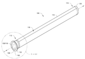
도 1은 본 기술의 일부 실시예에 따른 예시적인 필터 조립체의 사시도이다.
도 2는 도 1에 따른 예시적인 필터 조립체의 제2 사시도이다.
도 3은 도 1의 상세도이다.
도 4는 도 2의 상세도이다.
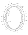
도 5는 도 3의 단면도이다.
도 6은 다른 예시적인 실시예의 단면도이다.
도 7은 또 다른 예시적인 실시예의 단면도이다.
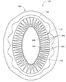
도 8은 도 3에 따른 예시적인 실시예의 단면도이다.
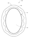
도 9는 도 3에 따른 다른 예시적인 실시예의 다른 단면도이다.
도 10은 예시적인 시스템의 일부의 대면도이다.
도 11은 일부 실시예에 따른 예시적인 시스템의 일부의 분해 사시도이다.
도 12는 일부 실시예에 따른 다른 예시적인 시스템의 일부의 분해 사시도이다.
도 13은 도 12에 따른 예시적인 시스템의 측면도이다.
도면은, 주로 명확성을 위해 제공된 것이며, 그 결과, 반드시 축척대로 도시된 것은 아니다. 또한, 파스너 전기적 구성요소(배선, 케이블 등) 등을 포함하지만 이에 제한되지 않는 다양한 구조/구성요소는, 도시된 실시예의 양태를 더 잘 예시하기 위해 또는 본원에서 설명되는 다양한 예시적인 실시예를 이해하는 데 이러한 구조/구성요소를 포함할 필요가 없는 경우에는 개략적으로 도시될 수 있거나 일부 또는 모든 도면에서 제거될 수 있다. 그러나, 특정 도면에서 이러한 구조/구성요소의 예시/설명의 부재를, 다양한 실시예의 범위를 어떤 식으로든 제한하는 것으로서 해석해서는 안 된다.The subject technology may be more fully understood and appreciated by consideration of the following detailed description of various embodiments in conjunction with the accompanying drawings.
1 is a perspective view of an exemplary filter assembly in accordance with some embodiments of the present technology.
FIG. 2 is a second perspective view of the exemplary filter assembly according to FIG. 1 ;
3 is a detailed view of FIG. 1 .
FIG. 4 is a detailed view of FIG. 2 .
FIG. 5 is a cross-sectional view of FIG. 3 .
6 is a cross-sectional view of another exemplary embodiment.
7 is a cross-sectional view of another exemplary embodiment.
Fig. 8 is a cross-sectional view of the exemplary embodiment according to Fig. 3;
Fig. 9 is another cross-sectional view of another exemplary embodiment according to Fig. 3;
10 is a front view of a portion of an example system.
11 is an exploded perspective view of a portion of an example system in accordance with some embodiments.
12 is an exploded perspective view of a portion of another example system in accordance with some embodiments.
13 is a side view of the exemplary system according to FIG. 12 ;
The drawings are provided primarily for clarity and, as a result, are not necessarily drawn to scale. In addition, various structures/components, including, but not limited to, fastener electrical components (wiring, cables, etc.), etc., may be used to better illustrate aspects of the illustrated embodiments or to understand the various exemplary embodiments described herein. Where it is not necessary to include such structures/components for construction purposes, they may be shown schematically or may be removed from some or all of the drawings. However, the absence of illustration/description of such structures/components in specific drawings should not be construed as limiting the scope of the various embodiments in any way.
도 1은 본 기술의 일부 실시예에 따른 예시적인 필터 조립체(100)의 사시도이고, 도 2는 예시적인 필터 조립체(100)의 제2 사시도를 도시한다. 필터 조립체(100)는 제1 단부(112)와 제2 단부(114)를 갖는 필터 매체(110)를 구비한다. 엔드캡(130)은 필터 매체의 제1 단부(112)에 결합된다. 엔드캡(130)은 중심 매체 개구(116)와 연통하는 엔드캡 개구(136)를 정의한다.1 is a perspective view of an
필터 매체(110)는 일반적으로 예를 들어 기상 유체와 같은 유체를 여과하도록 구성되지만, 일부 다른 실시예에서는, 필터 매체(110)가 액체를 여과하도록 구성된다. 필터 매체(110)는 일반적으로 중심 매체 개구(116) 둘레에 배치된다. 필터 매체(110)와 중심 매체 개구(116)는 필터 매체(110)의 제1 단부(112)로부터 필터 매체(110)의 제2 단부(114)를 향하여 축방향(a)으로 연장된다.
필터 매체(110)는 다양한 유형의 재료 및 재료들의 조합으로 구성될 수 있다. 일부 실시예에서, 필터 매체(110)는 주름진 구성(아래에서 도 8을 참조하여 더 상세히 설명됨)으로 된다. 일부 실시예에서, 필터 매체(110)는, 제1 단부(112)에서의 개방 단부, 제2 단부(114)를 향한 폐쇄 단부, 및 중심 매체 개구(116)를 정의하는 필터 매체의 하나 이상의 층인 백 구성이다. 다른 유형의 필터 매체(110)도 사용될 수 있다.
폐쇄부(120)는 필터 매체(110)의 제2 단부(114)를 향하여 정의될 수 있다. 폐쇄부(120)는 일반적으로 필터 매체(110)의 제2 단부(114)에서 중심 매체 개구(116)를 차단하도록 구성된다. 특히, 폐쇄부(120)는, 필터 매체(110)를 통해 필터 조립체(100)의 외부와 중심 매체 개구(116) 사이에서 연장되는 유체 흐름 경로를 정의하는 것을 돕는다. 폐쇄부(120)는, 필터 매체(110)가 주름진 구성으로 된 실시예와 같은 일부 실시예에서 필터 매체(110)의 제2 단부(114)에 결합된 제2 엔드캡일 수 있다. 다른 실시예에서, 폐쇄부(120)는, 필터 매체(110)가 백 구성으로 된 경우와 같이 필터 매체(110) 자체의 일부일 수 있다.The
일부 실시예에서, 중심 매체 개구(116)는 필터 조립체(100)의 하류측을 정의하고, 필터 매체(110)의 외면(118)은 필터 조립체(100)의 상류측을 정의한다. 다른 일부 실시예에서, 중심 매체 개구(116)는 필터 조립체(100)의 상류측을 정의하고 필터 매체(110)의 외면(118)은 필터 조립체(100)의 하류측을 정의한다.In some embodiments,
필터 조립체(100)는 일반적으로 여과 시스템에 설치되도록 구성된다. 그리고, 특히, 엔드캡(130)은, 일반적으로 시스템 구성요소 및 필터 매체(110)와의 밀봉을 형성하도록 구성되어 여과액이 여과되지 않은 유체로부터 격리되도록 구성되며, 이는 아래에서 더 자세히 설명할 것이다. 엔드캡(130)은 필터 매체(110)의 제1 단부(112)를 수용하도록 구성된 필터 매체 리셉터클(134)을 정의한다. 엔드캡 개구(136)는, 유체가 중심 매체 개구(116)를 통과할 수 있도록 중심 매체 개구(116)와 유체 연통한다. 엔드캡(130)은, 엔드캡 개구(136)를 둘러싸면서 맞닿는 내면(138)을 정의하며, 이는 특히 도 2의 상세도인 도 4에서 볼 수 있다.
엔드캡(130)은, 또한, 엔드캡(130) 둘레에 주변 밀봉면(140)을 정의하며, 이는 도 1의 상세도인 도 4에서 볼 수 있다. 주변 밀봉면(140)은 튜브시트 개구와 같은 여과 시스템의 구성요소에 의해 밀봉 가능하게 수용되도록 구성되며, 이는 아래에서 더 자세히 설명할 것이다. 주변 밀봉면(140)은 축방향으로 깊이(d)를 갖는다. 깊이(d)는, 주변 밀봉면(140)과의 밀봉을 형성하도록 구성된 시스템 구성요소를 수용하도록 크기가 정해질 수 있다. 일부 실시예에서, 깊이(d)의 범위는 3 mm 내지 30 mm, 4 mm 내지 15 mm, 또는 5 mm 내지 10 mm일 수 있다. 예시적인 일 실시예에서, 깊이(d)는 약 6 mm이다. 주변 밀봉면(140)은 엔드캡 개구(136) 주위로 연장되는 길이를 갖는다. 주변 밀봉면(140)의 제1 부분(142)은 엔드캡 개구(136)를 향하여 내측으로 돌출되고 따라서 오목부를 형성한다. 주변 밀봉면(140)의 제2 부분(144)은 엔드캡 개구(136)로부터 외측으로 돌출되고 따라서 돌출부를 형성한다. 제1 부분(142)과 제2 부분(144)은 축방향으로 정렬되어 있다.The
엔드캡 림(rim; 132)은 주변 밀봉면(140)으로부터 외측으로 연장된다. 일부 실시예에서, 엔드캡 림(132)은 엔드캡(130) 둘레의 주변 밀봉면(140)의 길이 둘레에서 주변 밀봉면(140)과 맞닿는다. 엔드캡 림(132)은, 또한, 일부 실시예에서 시스템 구성요소와의 밀봉을 형성하도록 구성될 수 있다. 예를 들어, 엔드캡 림(132)은 주변 밀봉면(140)과 맞닿는 밀봉 지지면(133)을 정의할 수 있다. 일부 실시예에서, 밀봉 지지면(133)은 평면이다. 밀봉 지지면(133)은 주변 밀봉면(140)에 직교할 수 있다.An
엔드캡(130)은 다양한 상이한 유형의 재료 및 재료들의 조합으로 구성될 수 있다. 일부 실시예에서. 엔드캡(130)은 우레탄으로 구성된다. 일부 실시예에서, 엔드캡(130)은, 주변 밀봉면(140) 주위의 밀봉 지지면(133)의 적어도 일부 및 주변 밀봉면(140) 둘레와 같은 하나 이상의 표면을 가로질러 배치된 개스킷 재료를 갖는 주조 알루미늄으로 구성된다. 일부 실시예에서, 엔드캡(130)은 적어도 부분적으로 약 30 Shore A 내지 70 Shore A의 경도계를 갖는 재료로 구성된다.
도 5는 축방향(a)에 직교하는 평면에서 엔드캡(130)의 단면도를 도시한다. 이 도면에서, 주변 밀봉면(140)은 엔드캡 개구(136) 주위에 루프를 형성하는 라인이다. 주변 밀봉면(140)에 의해 형성된 루프는 길이방향 축(L)에 평행한 방향으로 길쭉한 형상이다. 유사하게, 엔드캡 개구(136)도 길이방향(L)으로 길쭉한 형상이다.5 shows a cross-sectional view of the
특히, 본 도면에서는 주변 밀봉면(140)의 제1 부분(142)과 제2 부분(144)의 프로파일을 볼 수 있다. 또한, 엔드캡(130)이 주변 밀봉면(140)의 복수의 제1 부분(142) 및 주변 밀봉면(140)의 제2 부분들(144)을 형성한다는 점을 알 수 있다. 적어도 하나의 제1 부분(142)은 주변 밀봉면(140)의 적어도 하나의 제2 부분(144)과 맞닿는다. 실제로, 복수의 제1 부분(142)은 복수의 제2 부분(144)과 교번한다. 복수의 제1 부분(142)과 제2 부분들(144)은 곡선(c)을 따라 연장되는 굴곡부를 누적 형성한다.In particular, the profile of the
주변 밀봉면(140)의 단면은 제1 단부(143), 제2 단부(145), 제1 세장형 측부(147), 및 제2 세장형 측부(149)를 정의한다. 제1 부분(142) 및 제2 부분(144)은 제1 세장형 측부(147) 상에 정의된다. 제1 부분(142) 및 제2 부분(144)은 제2 세장형 측부(149) 상에도 정의된다.A cross-section of the
본 실시예에서, 주변 밀봉면(140)은 길이방향 축(L)에 대해 대칭이지만, 일부 실시예에서 주변 밀봉면(140)은 대칭이 아니다. 또한, 주변 밀봉면(140)의 제1 부분(142)과 제2 부분(144) 각각은 반복되는 규칙적인 프로파일 형상을 갖지만, 일부 실시예에서, 제1 부분(142)과 제2 부분(144)의 프로파일 형상은 규칙적이지 않으며/않거나 반복되지 않는다. 또한, 적어도 하나의 제1 부분(142)은 다른 제1 부분(142)과는 상이한 프로파일 형상을 가질 수 있다. 유사하게, 적어도 하나의 제2 부분(144)은 다른 제2 부분(144)과는 상이한 프로파일 형상을 가질 수 있다.In this embodiment, the
주변 밀봉면(140)은, 본원에 참고로 원용되는 "Filter Cartridges: Air Cleaner Assemblies; Housings; Features; Components; and, Methods라는 명칭으로 2018년 8월 8일에 출원된 국제출원번호 PCT/US2018/045819에 개시된 밀봉면에 따른 기하학적 구조, 측정값, 및 비(ratio)를 갖는 돌출부와 오목부를 통합하는 구조를 가질 수 있다.
주변 밀봉면(140)의 총 길이는 P1이라고 칭할 수 있고, 돌출부와 오목부에 의해 정의된 주변 밀봉면(140)의 부분들의 총 길이는 P2라고 칭할 수 있으며, 여기서 "총 길이"는 이 맥락에서 윤곽을 포함한 밀봉면 거리를 가리킨다. 현재 도면에서, P2는, 예를 들어, 오목부들과 맞닿는 돌출부들을 정의하는 제2 섹션의 단부 지점들(10c, 10d) 사이의 주변 밀봉면(140)의 길이가 더해진, 오목부들과 맞닿는 돌출부들을 정의하는 제1 섹션의 단부 지점들(10a, 10b) 사이의 주변 밀봉면(140)의 길이이다. P1 대 P2의 비는 일반적으로 1.0보다 크지만, 일부 실시예에서, P1 대 P2의 비는 약 1.0과 동일하다. 일부 실시예에서, P1 대 P2의 비는 1.1 내지 3.0이다. 일부 실시예에서, P1 대 P2의 비는 1.2 내지 1.7이다. 일례로, P1 대 P2의 비는 약 1.5와 같다.The total length of the
돌출부와 오목부의 크기는, 특정 돌출부와 인접하는 오목부 사이의 깊이(D1)에 의한 것과 같은 다양한 방식으로 특징화될 수 있다. 통상적으로, 돌출부/오목부 깊이(D1)는 70 mm 이하, 종종 50 mm 이하, 일반적으로 30 mm 이하이다. 통상적으로, 돌출부/오목부 깊이(D1)는 적어도 5 mm, 적어도 10 mm, 때로는 적어도 15 mm이다. 돌출부/오목부 깊이(D1)는 6 mm 또는 9 mm와 같이 일부 실시예에서 5 mm 내지 15 mm일 수 있다. 대안도 가능하다.The size of protrusions and recesses can be characterized in a variety of ways, such as by the depth D1 between a particular protrusion and an adjacent recess. Typically, the protrusion/recess depth D1 is 70 mm or less, often 50 mm or less, typically 30 mm or less. Typically, the projection/recess depth D1 is at least 5 mm, at least 10 mm, sometimes at least 15 mm. The protrusion/recess depth D1 may be between 5 mm and 15 mm in some embodiments, such as 6 mm or 9 mm. Alternatives are possible.
일부 실시예에서, 제1 부분(142)의 오목부는 반경(R1)을 정의한다. 제1 부분(R1)의 반경 범위는 4 mm 내지 40 mm일 수 있다. 일부 실시예에서, 제1 부분(R1)의 반경은 약 4 mm, 6 mm, 12 mm, 16 mm, 24 mm, 33 mm, 또는 39 mm일 수 있다. 일부 실시예에서, 제2 부분(144)의 돌출부는 반경(R2)을 정의한다. 제2 부분(R2)의 반경 범위는 4 mm 내지 40 mm일 수 있다. 일부 실시예에서, 제2 부분(R2)의 반경은 약 4 mm, 5 mm, 6 mm, 11 mm, 16 mm, 17 mm, 19 mm, 또는 26 mm일 수 있다. 또한, 인접한 제1 부분들 또는 인접한 제2 부분들 사이의 거리, 예를 들어, 도 5의 거리(dd)는 일반적으로 10 mm보다 길다. 일부 실시예에서, 거리(dd) 범위는 15 mm 내지 70 mm, 30 mm 내지 50 mm, 또는 35 mm 내지 45 mm일 수 있다. 일례로, 거리(dd)는 약 42 mm일 수 있다. 주변 밀봉면(140)의 다수의 제1 부분과 제2 부분이 있는 경우, 각각의 제1 부분(또는 제2 부분)은 반드시 동일한 깊이, 반경, 및/또는 기하학적 구조를 가질 필요가 없으며, 인접한 제1 부분들 및 인접한 제2 부분들 사이의 거리는 가변될 수 있다는 점에 주목한다.In some embodiments, the recess of the
도 6은 필터 조립체의 다른 예시적인 엔드캡(200)을 통한 단면도를 도시한다. 필터 조립체는, 모순되는 경우를 제외하고는 본원에서 설명되는 다른 필터 조립체를 따를 수 있다. 도 5에 도시된 단면과 같이, 여기서 단면은 필터 조립체의 축방향에 직교하는 평면에 있다. 엔드캡(200)은 엔드캡 개구(230) 및 엔드캡(200) 둘레의 주변 밀봉면(220)을 정의한다. 주변 밀봉면(220)은 엔드캡 개구(230) 주위로도 연장된다. 엔드캡(200)은, 또한, 주변 밀봉면(220)으로부터 외측으로 연장되는 엔드캡 림(210)을 갖는다.6 shows a cross-sectional view through another
주변 밀봉면(220)은, 엔드캡 개구(230) 및 엔드캡(200)으로부터 외측으로 연장되는 제1 돌출부(222)와 제2 돌출부(224)를 갖는다. 이 예에서, 주변 밀봉면(220)의 프로파일은 (도 5에 도시된 예와는 달리) 대칭이 아니다. 제1 오목부(226)와 제2 오목부(228)는 제1 돌출부(222)의 돌출 형상으로 인해 제1 돌출부(222)의 각 측부와 맞닿는다. 돌출부와 오목부에 의해 정의된 주변 밀봉면(220)의 총 길이에 대한 주변 밀봉면(220)의 총 길이의 비는 도 5를 참조하여 전술한 비와 유사할 수 있다.The
돌출부/오목부 깊이(D2)는 제1 돌출부(222)와 (제1 오목부(226)와 같은) 인접한 오목부 사이에 정의될 수 있다. 돌출부/오목부 깊이는 도 5를 참조하여 전술한 깊이와 유사할 수 있다. 제1 돌출부(222)는 반경(R3)을 정의할 수 있다. 제1 돌출부(R3)의 반경은 도 5를 참조하여 전술한 제1 부분(R1)의 반경과 유사할 수 있다. 제2 돌출부(224)는 제1 돌출부(R3)의 반경과 유사하거나 상이한 반경을 정의할 수 있다. 제2 오목부(228)는 반경(R4)을 정의할 수 있다. 제2 오목부(228)의 반경(R4)은 도 5를 참조하여 전술한 제2 부분(R2)의 반경과 유사할 수 있다. 제1 오목부(226)는 제2 오목부(228)와 유사하거나 상이한 반경을 정의할 수 있다.The protrusion/recess depth D2 may be defined between the
도 7은 필터 조립체의 다른 예시적인 엔드캡(300)을 통한 단면도를 도시한다. 필터 조립체는, 모순되는 경우를 제외하고는 본원에서 설명되는 다른 필터 조립체를 따를 수 있다. 도 5에 도시된 단면과 같이, 여기서 단면은 필터 조립체의 축방향에 직교하는 평면에 있다. 엔드캡(300)은 엔드캡 개구(330) 및 엔드캡(300) 주위의 주변 밀봉면(320)을 정의한다. 주변 밀봉면(320)은 엔드캡 개구(330) 둘레로도 연장된다. 엔드캡(300)은, 또한, 주변 밀봉면(320)으로부터 외측으로 연장되는 엔드캡 림(310)을 갖는다.7 shows a cross-sectional view through another
주변 밀봉면(320)은 엔드캡(300)으로부터 외측으로 연장하는 제1 돌출부(322)와 제2 돌출부(324)를 갖는다. 제1 돌출부(322)는 주변 밀봉면(320)에 의해 정의된 맞닿는 제1 오목부(326)에 의해 그 자체로 특징화될 수 있다. 제2 돌출부(324)도 유사하게 형성된다. 주변 밀봉면(320)은, 또한, 제3 돌출부(328) 및 제2 오목부(342)와 맞닿는 제4 돌출부(340)를 갖는다.The
돌출부와 오목부에 의해 정의된 주변 밀봉면(320)의 총 길이에 대한 주변 밀봉면(320)의 총 길이의 비는 도 5를 참조하여 전술한 비와 유사할 수 있다. 돌출부/오목부 깊이(D3)는 제1 돌출부(322)와 제1 오목부(326)(인접한 오목부임) 사이에 정의될 수 있다. 돌출부/오목부 깊이(D3)는 도 5를 참조하여 전술한 깊이와 유사할 수 있다. 제1 돌출부(322)는 반경(R5)을 정의할 수 있다. 제1 돌출부(R5)의 반경은 도 5를 참조하여 전술한 제1 부분(R1)의 반경과 유사할 수 있다. 제2 돌출부(324)는 제1 돌출부(R5)의 반경과 유사하거나 상이한 반경을 정의할 수 있다. 제1 오목부(326)는 반경(R6)을 정의할 수 있다. 제1 오목부(326)의 반경(R6)은 도 5를 참조하여 전술한 제2 부분(R2)의 반경과 유사할 수 있다. 제1 오목부(326)는 제2 오목부(342)와 유사하거나 상이한 반경을 정의할 수 있고, 제3 및 제4 돌출부(328, 340)는 각각 제1 돌출부(322)와 유사하거나 상이한 반경을 정의할 수 있다.The ratio of the total length of the
도 5 내지 도 7의 예시적인 주변 밀봉면의 프로파일은 반경을 정의하는 돌출부와 오목부를 갖는 반면, 일부 다른 실시예에서, 돌출부 및/또는 오목부 중 하나 이상은 곡률을 정의하지 않는 직선 세그먼트를 갖는다. 이러한 실시예에서, 주변 밀봉면의 프로파일은, 직선 세그먼트를 다른 직선 세그먼트에 연결하거나 직선 세그먼트를 곡선 세그먼트에 연결하는 코너를 정의할 수 있다.The profile of the exemplary peripheral sealing surface of FIGS. 5-7 has projections and recesses defining a radius, while in some other embodiments, one or more of the projections and/or recesses have straight segments that do not define a curvature. . In such an embodiment, the profile of the peripheral sealing surface may define a corner connecting a straight segment to another straight segment or connecting a straight segment to a curved segment.
도 8은 도 1 내지 도 5에 따른 필터 조립체(100)의 제2 단면도의 일례이다. 단면은 도 3의 필터 매체(110)를 통과하며 축방향에 직교한다. 본 예에서, 필터 매체(110)는 주름진 필터 매체이다. 주름진 필터 매체는 축방향으로 연장되는 복수의 주름(306)을 갖는다. 주름 접힘부의 제1 세트(302)는 필터 매체(110)의 외주에 근접하고, 주름 접힘부의 제2 세트(304)는 중심 매체 개구(116)를 정의한다. 본 실시예에서, 라이너(308)는, 주름진 필터 매체(110) 내에 배치되고 중심 매체 개구(116)를 상호 정의한다. 일부 실시예에서, 라이너(308)는 생략될 수 있다. 중심 매체 개구(116)는 길쭉한 형상이고 대략 타원형이다.8 is an example of a second cross-sectional view of the
도 9는 도 1 내지 도 5에 따른 필터 조립체(100)의 제2 단면도의 다른 일례이다. 단면은 도 3의 필터 매체(110)를 통과하며 축방향에 직교한다. 현재 예에서, 필터 매체(110)는, 백 구성으로 되어 있고, 유사하게 길쭉한 형상인 중심 매체 개구(116)를 형성한다. 도 8의 예와는 달리, 여기서 필터 매체는 주름진 구조를 갖지 않는다.9 is another example of a second cross-sectional view of the
도 10은 일부 실시예에 따른 예시적인 시스템의 일부의 대면도이고, 도 11은 이러한 시스템의 일부의 분해 사시도이다. 시스템(400)은, 필터 개구(420)를 정의하는 튜브시트(410), 및 필터 개구(420) 둘레에서 튜브시트(410)와 정합하도록 구성된 필터 조립체(100)를 갖는다.10 is a front view of a portion of an exemplary system in accordance with some embodiments, and FIG. 11 is an exploded perspective view of a portion of such a system.
필터 조립체(100)는, 필터 조립체(100)가 축방향(a)으로 연장되는 필터 매체(110) 및 필터 매체(110)의 제1 단부(112)에 결합된 엔드캡(130)을 갖는다는 점에서 본원의 다른 곳에서 설명된 필터 조립체를 따를 수 있다. 엔드캡(130)은 필터 매체(110)의 중심 매체 개구와 연통하는 엔드캡 개구(136)를 정의하고, 엔드캡(130)은 엔드캡 개구(136)로부터 외측으로 연장되는 엔드캡 림(132)을 갖는다. 현재 설명되는 도면에서는 보이지 않지만, 필터 조립체(100)는 도 5에 도시된 프로파일을 따르는 프로파일을 갖는 주변 밀봉면(140)을 갖는다.The
튜브시트(410)는 일반적으로 하나 이상의 필터 조립체를 수용하도록 구성된다. 튜브시트(410)는, 일반적으로 길이방향의 길이(L) 및 폭방향의 폭(W)을 갖는 실질적으로 평면인 재료 시트이다. 튜브시트(410)는 다양한 재료 및 재료들의 조합으로 구성되고, 일례로,튜브시트(410)는 금속으로 구성된다. 다른 일례로, 튜브시트(410)는 유리 섬유로 구성된다. 길이(L) 및 폭(W)은 일반적으로 필터 조립체(100)의 축방향(a)에 직교하는 평면에 있다. 재료 시트는 재료 시트의 길이(L)와 폭(W)에 걸쳐 일련의 필터 개구(420)를 정의한다. 일련의 필터 개구의 필터 개구(420) 각각은 축방향(a)으로 재료 시트를 통해 연장된다.
필터 개구(420) 각각은 축방향(a)에 직교하는 길쭉한 형상의 프로파일을 가질 수 있으며, 이는 특히 도 10에서 볼 수 있다. 이와 같이, 필터 개구(420) 각각은 길이방향 축(l)을 가질 수 있다. 튜브시트(410) 상에 원하는 수의 필터 개구(420)를 수용하기 위해, 필터 개구들(420) 중 일부는 튜브시트 상의 다른 필터 개구들(420)과는 상이하게 정렬될 수 있다. 일부 실시예에서, 제1 복수의 필터 개구(430)는, 각각의 대응하는 길이방향 축(l1)이 튜브시트(410)를 가로질러 반경 방향으로 배열되도록 튜브시트(410)에 정의된다. 일부 실시예에서, 제2 복수의 필터 개구(440)는, 각각의 대응하는 길이방향 축(l2)이 튜브시트(410)를 가로질러 반경 방향에 대한 접선 방향으로 배열되도록 튜브시트(410)를 가로질러 반경 방향으로 정의된다. 일부 실시예에서, 튜브시트(410)에 의해 정의된 제1 필터 개구(460)는 제1 길이방향 축(l1)을 갖고, 튜브시트(410)에 의해 정의된 제2 필터 개구(462)는 제2 길이방향 축(l2)을 갖고, 제1 길이방향 축(l1)과 제2 길이방향 축(l2)은 10도 내지 90도 떨어져 있다.Each of the
필터 개구는, 필터 개구(420) 각각으로부터 외측으로 연장되는 돌출부(422) 및 필터 개구(420) 각각 내로 연장되는 오목부(424)를 형성한다. 돌출부(422)와 오목부(424)는 축방향으로 정렬된다.The filter openings define a
다양한 실시예에서, 필터 조립체(100)의 엔드캡(130)은 일반적으로 필터 개구(420) 둘레에서 튜브시트(410)와 정합하도록 구성된다. 특히, 엔드캡(130)의 주변 밀봉면(140)(도 3 참조)은 튜브시트(410)와 밀봉을 형성하도록 구성된다. 일부 실시예에서, 튜브시트(410)는 주변 밀봉면(140)과 압축 끼워맞춤을 형성한다. 도 5의 주변 밀봉면의 단면도와 도 10의 필터 개구의 프로파일을 비교함으로써 알 수 있는 바와 같이, 필터 개구(420)는 주변 밀봉면(140)을 수용하도록 구성된다. 도 5에 대해 설명한 바와 같이, 주변 밀봉면은, 적어도 엔드캡 개구(136)를 향하여 내측으로 돌출되는 제1 부분(142) 및 엔드캡 개구(136)로부터 외측으로 돌출되는 제2 부분(144)을 정의한다. 필터 조립체(100)를 수용하도록 구성된 필터 개구(420)는, 주변 밀봉면(140)의 제2 부분(144)을 수용하도록 구성된 대응하는 외향 돌출부(422) 및 주변 밀봉면(140)의 제1 부분(142)을 수용하도록 구성된 대응하는 오목부(424)를 정의한다.In various embodiments, the
본 예에서, 필터 개구(420) 각각은 축방향으로 정렬된 복수의 돌출부(422) 및 복수의 오목부(424)를 정의한다. 여기서, 돌출부(422)는 각각의 필터 개구(420)의 일부에 대해 오목부(424)와 교번한다. 각각의 필터 개구(420)의 프로파일은 제1 세장형 측부(452), 제2 세장형 측부(454), 제1 단부(456), 및 제2 단부(458)를 정의한다. 돌출부(422)는 제1 세장형 측부(452) 상의 필터 개구(420)로부터 연장된다. 이러한 특정 예에서, 필터 개구(420)의 각각의 세장형 측부(452, 454)는, 곡선을 따라 연장되는 굴곡부를 누적 형성하는 복수의 돌출부(422)와 복수의 오목부(424)를 갖는다. 오목부(424)는 제2 세장형 측부(454) 상의 각 필터 개구 내로 연장된다. 도 5를 참조하여 전술한 주변 밀봉면의 프로파일과 유사하게, 여기서 각 필터 개구(420)의 프로파일은 대칭이다.In this example, each of the
본원에 개시된 기술을 따르는 필터 개구(420) 및 필터 엔드캡(130)의 주변 밀봉면의 구성은 다양한 이점을 가질 수 있다. 예를 들어, 필터 개구(420) 구성은, 사용자가 부적합한 필터 조립체를 필터 개구(420)에 설치할 수 없도록 하는 안전 기능일 수 있다. 다른 일례로, 시스템 동작 동안의 유체 흐름은, 필터 조립체(100)와 튜브시트(410) 간의 밀봉을 제거하기 위해 튜브시트(410)에 대해 필터 조립체(100)를 이동시킬 수 있는 힘을 필터 조립체(100)에 가할 수 있다. 주변 밀봉면(140)(도 5) 및 튜브시트(410)에 의해 상호 정의되는 계면의 구조는, 엔드캡(130)과 튜브시트(410) 간의 구조적 강성을 개선하여 시스템 동작 동안 필터 조립체(100)가 튜브시트(410)로부터 분리될 가능성을 감소시킬 수 있다. 이러한 개선된 구조적 강성은, 또한, 유체가 필터 조립체(100)(특히 엔드캡(130))와 튜브시트(410) 간의 밀봉 영역의 일부를 통해 누출됨으로써 필터 조립체(100)를 우회하는 것을 방지할 수 있다.The configuration of the
일부 실시예에서, 엔드캡 림(132)에 의해 정의된 밀봉 지지면(133)(도 3)은, 필터 개구(420) 둘레에서 튜브시트(410)의 주면(412)(도 11)과 맞닿도록 구성된다. 이러한 모든 실시예는 아니지만 일부 실시예에서, 밀봉 지지면(133) 및 주면(412)은 밀봉을 형성하도록 구성된다.In some embodiments, the sealing support surface 133 ( FIG. 3 ) defined by the
엔드캡의 주변 밀봉면과 튜브시트는 일반적으로 엔드캡과 튜브시트 간에 정합하여 유체 밀봉을 형성하도록 구성된다는 점에 주목한다. 이와 같이, 주변 밀봉면에 의해 정의된 루프가 (도 6 및 도 7과 같이) 도 5에 도시된 형상으로부터 벗어나는 프로파일 형상을 갖는 실시예에서, 튜브시트에 의해 정의된 필터 개구는, 튜브시트가 엔드캡의 주변 밀봉면 및 밀봉 지지면과 정합할 수 있도록 대응하는 프로파일 형상을 갖는다. 엔드캡과 튜브시트 간의 유체 밀봉은 상류측의 미리 여과된 유체와 여과액 간의 시스템 분리를 제공한다.It is noted that the tubesheet and the peripheral sealing surface of the endcap are generally configured to mate between the endcap and the tubesheet to form a fluid seal. As such, in embodiments where the loop defined by the peripheral sealing surface has a profile shape that deviates from the shape shown in FIG. 5 (such as in FIGS. 6 and 7 ), the filter opening defined by the tubesheet is It has a corresponding profile shape to be able to mate with the peripheral sealing surface and sealing support surface of the end cap. The fluid seal between the endcap and tubesheet provides system separation between the upstream pre-filtered fluid and the filtrate.
본원에 개시된 기술의 예시적인 일부 구현예에서, 튜브시트는 공간에서 수평면에 대략 평행하게 배향되고, 튜브시트에 설치된 필터 조립체는 대략 수직인 축방향을 갖는다. 그러나 다른 일부 구현예는 대체 배향을 가질 수 있다.In some exemplary embodiments of the techniques disclosed herein, the tubesheet is oriented approximately parallel to the horizontal plane in space, and the filter assembly installed in the tubesheet has an axial direction approximately perpendicular. However, some other embodiments may have alternative orientations.
도 12는 일부 실시예에 따른 예시적인 대체 시스템(500)의 일부의 분해 사시도이고, 도 13은 이러한 예시적인 시스템(500)의 측면도이다. 예시적인 시스템(500)은 튜브시트(510) 및 필터 조립체(600)를 갖고, 필터 조립체(600)는 필터 매체(610), 엔드캡(630), 및 확장 삽입부(700)를 갖는다.12 is an exploded perspective view of a portion of an
전술한 예와 유사하게, 필터 조립체(600)는 필터 매체(610)의 제1 단부에서 엔드캡(630)에 결합된 필터 매체(610)를 갖는다. 튜브시트(510)는 필터 엔드캡(630)과 정합하도록 구성된 복수의 필터 개구(520)를 정의한다. 필터 매체(610), 엔드캡(630), 및 튜브시트(510)는, 전술한 예를 따를 수 있고, 전술한 바와 같이 수정을 통합할 수 있다. 예를 들어, 튜브시트(510)의 필터 개구(520)는 도 11에 관하여 전술한 특정 구성을 보여주고 있으나, 필터 개구(520)는 대체 구성을 가질 수 있다.Similar to the example described above, the
이전의 예들과는 달리, 예시적인 본 시스템(500)은, 엔드캡(630)의 내면(638)과 압축 끼워맞춤을 형성하도록 구성된 확장 삽입부(700)를 통합하며, 여기서, 엔드캡(630)의 내면(638)은 엔드캡 개구(636)를 둘러싸면서 맞닿는다. 일부 실시예에서, 확장 삽입부(700)는 엔드캡 개구(636)를 통해 엔드캡(630)에 확장력을 가하도록 구성된다. 일부 실시예에서, 확장 삽입부(700) 및 튜브시트(510)는 엔드캡(630)에 압축력을 가하도록 구성될 수 있다. 이러한 압축력은 필터 조립체(600)를 튜브시트(510)에 고정하는 것을 도울 수 있다.Unlike previous examples, the present
확장 삽입부(700)는 엔드캡 개구(636) 내로 삽입되도록 구성된 삽입 부분(702)을 갖는다. 삽입 부분(702)은 외면(720) 및 삽입부 개구(710)를 정의한다. 외면(720)은 엔드캡(630)의 내면(638)과의 압축 끼워맞춤을 정의하도록 구성된다. 삽입부 개구(710)는, (필터 매체(610)에 의해 정의된 중심 매체 개구와 유체 연통하는) 엔드캡 개구(636)와 유체 연통하도록 구성된다. 확장 삽입부(700)는 삽입부 개구(710) 주위로 연장되는 플랜지(730)를 갖는다. 플랜지(730)는, 엔드캡(630) 림(632)의 대향면(640)과 맞닿도록 구성된 플랜지 표면(733)(도 13)을 정의한다. 일부 실시예에서, 플랜지 표면(733)은 실질적으로 평면이다.
확장 삽입부(700)의 외면(720)과 엔드캡(630)의 내면(638) 사이의 계면은, 전술한 튜브시트와 엔드캡의 주변 밀봉면 사이의 계면과 유사한 기하학적 구조, 측정값, 및 구성을 가질 수 있다. 특히, 확장 삽입부(700)의 외면(720)은, 삽입부 개구(710)를 향하여 내측으로 연장되는 오목부(724) 및 삽입부 개구(710)로부터 외측으로 연장되는 돌출부(722)를 정의한다. 오목부(724)와 돌출부(722)는 축방향으로 정렬되어 있다.The interface between the
엔드캡(630)의 내면(638)은 외면(720)과 정합하도록 구성된 결합 기능부를 정의한다. 특히, 엔드캡(630)의 내면(638)은 엔드캡 개구(636) 내로 연장되는 정합 돌출부(644)를 정의한다. 정합 돌출부(644)는 확장 삽입부(700)의 외면(720)의 오목부(724)에 의해 수용되도록 구성된다. 엔드캡(630)의 내면(638)은 엔드캡 개구(636)로부터 외측으로 연장되는 정합 오목부(642)를 정의하며, 정합 오목부(642)는 확장 삽입부(700)의 외면(720)의 돌출부(722)를 수용하도록 구성된다.An
다양한 실시예에서, 확장 삽입부(700)의 삽입 부분(702)의 외면(720)은 복수의 오목부(724) 및 돌출부들(722)을 정의할 수 있다. 일부 실시예에서, 오목부(724)와 돌출부(722)는 외면(720)의 길이의 일부를 따라 교번할 수 있다. 일부 실시예에서, 오목부(724)와 돌출부(722)는 굴곡형 밀봉면을 정의할 수 있다. 이러한 실시예에서, 엔드캡(630)의 내면(638)은 확장 삽입부(700)의 삽입 부분(702)을 수용하도록 대응하는 정합 기능부를 정의한다.In various embodiments, the
현재 예를 따르는 예들에서, 확장 삽입부(700)는 중심 매체 개구와 유체 연통하는 제3 흐름 채널(732)을 정의한다. 제3 흐름 채널(732)은, 엔드캡 개구(636)(및 이에 따른 삽입부 개구(710))를 통해 필터 매체 개구 내로 압축 공기를 펄싱함으로써 필터 매체(610)가 세정되는 시스템에서 기류를 용이하게 하는 데 사용될 수 있다.In examples according to the present example, the
다양한 실시예에서, 확장 삽입부(700)는 복수의 제3 흐름 채널(732)을 정의한다. 제3 흐름 채널(들)(732)은 엔드캡 개구(636)와 유체 연통할 수 있다. 제3 흐름 채널(들)(732)은 축방향(a)으로 연장될 수 있다. 일부 실시예에서, 제3 흐름 채널(들)(732)은 삽입부 개구(710)에 평행하다. 제3 흐름 채널(들)(732)은 플랜지(730) 및 확장 삽입부(700)의 삽입 부분(702)을 통해 연장될 수 있다. 제3 흐름 채널(들)(732)은 돌출부(722)를 정의하는 삽입 부분(702)의 외면(720)의 일부를 통해 연장될 수 있다.In various embodiments, the
본 실시예에서는 삽입 부분(702)의 외면(720)이 오목부 및 돌출부를 정의하는 반면, 다른 일부 실시예에서는 삽입 부분의 외면(및 이에 따른 엔드캡의 내면)이 오목부 및 돌출부를 정의하지 않는다는 점에 주목한다. 또한, 본 실시예에서는 튜브시트(510)의 필터 개구(520)가 오목부 및 돌출부(엔드캡의 주변 밀봉면의 오목부 및 돌출부에 대응함)를 정의하지만, 다른 일부 실시예에서는 필터 개구(520) 및 주변 밀봉면이 오목부 및 돌출부를 정의하지 않는다.In this embodiment, the
실시예의 재작성Rewrite of Examples
실시예 1. 필터 조립체로서, Example 1. A filter assembly comprising:
중심 매체 개구의 둘레에 배치되고 제1 단부와 제2 단부를 갖는 필터 매체로서, 상기 중심 매체 개구는 상기 제2 단부를 향하여 상기 제1 단부로부터 축방향으로 연장되는, 필터 매체; a filter medium disposed around a central media opening and having a first end and a second end, the central media opening extending axially from the first end toward the second end;
상기 필터 매체의 상기 제1 단부에 결합되고, 상기 중심 매체 개구와 유체 연통하는 개구를 정의하는 엔드캡; an end cap coupled to the first end of the filter media and defining an opening in fluid communication with the central media opening;
상기 엔드캡 개구를 둘러싸면서 맞닿는 내면; 및 an inner surface abutting while enclosing the end cap opening; and
상기 엔드캡 둘레의 주변 밀봉면을 포함하고, a peripheral sealing surface around the end cap;
상기 주변 밀봉면의 제1 부분은 상기 엔드캡 개구를 향하여 내측으로 돌출되고, 상기 주변 밀봉면의 제2 부분은 상기 엔드캡 개구로부터 외측으로 돌출되고, 상기 제1 부분과 상기 제2 부분은 축방향으로 정렬되고, 상기 주변 밀봉면은 상기 축방향에 직교하는 제1 단면에 있어서 길쭉한 형상의 루프를 형성하는, 필터 조립체.A first portion of the perimeter sealing surface protrudes inwardly toward the end cap opening, a second portion of the perimeter sealing surface protrudes outwardly from the end cap opening, and the first portion and the second portion are axial directionally aligned, and wherein the peripheral sealing surface forms an elongated loop in a first cross-section orthogonal to the axial direction.
실시예 2. 실시예 1 및 3 내지 12 중 어느 한 실시예에 있어서, 상기 엔드캡 개구는 상기 제1 단면에 있어서 길쭉한 형상인, 필터 조립체.Embodiment 2. The filter assembly of any of Embodiments 1 and 3-12, wherein the end cap opening is elongated in the first cross-section.
실시예 3. 실시예 1, 2 및 4 내지 12 중 어느 한 실시예에 있어서, 상기 중심 매체 개구는 상기 축방향에 직교하는 제2 단면에 있어서 길쭉한 형상인, 필터 조립체.Embodiment 3. The filter assembly of any of Embodiments 1, 2 and 4-12, wherein the central media opening is elongated in a second cross-section orthogonal to the axial direction.
실시예 4. 실시예 1 내지 3 및 5 내지 12 중 어느 한 실시예에 있어서, 외면과 삽입부 개구를 정의하는 확장 삽입부를 더 포함하고, 상기 확장 삽입부의 외면은 상기 엔드캡의 내면과의 압축 끼워맞춤을 정의하도록 구성된, 필터 조립체.Embodiment 4. The embodiment of any of Embodiments 1-3 and 5-12, further comprising an expanding insert defining an outer surface and an insert opening, wherein the outer surface of the expanded insert is compressed with an inner surface of the endcap A filter assembly configured to define a fit.
실시예 5. 실시예 1 내지 4 및 6 내지 12 중 어느 한 실시예에 있어서, 상기 확장 삽입부는 상기 중심 매체 개구와 유체 연통하는 제3 흐름 채널을 정의하는, 필터 조립체.Embodiment 5 The filter assembly of any of Embodiments 1-4 and 6-12, wherein the expanding insert defines a third flow channel in fluid communication with the central media opening.
실시예 6. 실시예 1 내지 5 및 7 내지 12 중 어느 한 실시예에 있어서, 상기 확장 삽입부의 외면은 상기 삽입부 개구를 향하여 내측으로 연장되는 오목부 및 상기 삽입부 개구로부터 외측으로 연장되는 돌출부를 정의하고, 상기 오목부와 상기 돌출부는 축방향으로 정렬되고, 상기 내면은 정합 기능부들을 정의하는, 필터 조립체.Embodiment 6. The embodiment according to any one of Embodiments 1 to 5 and 7 to 12, wherein the outer surface of the expansion insert has a concave portion extending inward toward the insert opening and a protrusion extending outwardly from the insert opening wherein the recess and the protrusion are axially aligned and the inner surface defines mating features.
실시예 7. 실시예 1 내지 6 및 8 내지 12 중 어느 한 실시예에 있어서, 상기 주변 밀봉면의 제1 단면은 제1 단부, 제2 단부, 제1 세장형 측부, 및 제2 세장형 측부를 정의하고, 상기 제1 부분과 상기 제2 부분은 상기 제1 세장형 측부 상에 정의되는, 필터 조립체.Embodiment 7. The embodiment of any of Embodiments 1-6 and 8-12, wherein the first cross-section of the peripheral sealing surface comprises a first end, a second end, a first elongate side, and a second elongate side and wherein the first portion and the second portion are defined on the first elongate side.
실시예 8. 실시예 1 내지 7 및 9 내지 12 중 어느 한 실시예에 있어서, 상기 주변 밀봉면의 제1 부분은 상기 주변 밀봉면의 제2 부분과 맞닿는, 필터 조립체.Embodiment 8 The filter assembly of any of Embodiments 1-7 and 9-12, wherein a first portion of the peripheral sealing surface abuts a second portion of the peripheral sealing surface.
실시예 9. 실시예 1 내지 8 및 10 내지 12 중 어느 한 실시예에 있어서, 상기 엔드캡은 상기 주변 밀봉면의 복수의 제1 부분 및 상기 주변 밀봉면의 제2 부분들을 정의하는, 필터 조립체.Embodiment 9 The filter assembly of any of embodiments 1-8 and 10-12, wherein the end cap defines a plurality of first portions of the peripheral sealing surface and second portions of the peripheral sealing surface .
실시예 10. 실시예 1 내지 9, 11 및 12 중 어느 한 실시예에 있어서, 상기 제1 부분들과 상기 제2 부분들은 교번하는, 필터 조립체.Embodiment 10 The filter assembly of any of embodiments 1-9, 11 and 12, wherein the first portions and the second portions alternate.
실시예 11. 실시예 1 내지 10 및 12 중 어느 한 실시예에 있어서, 상기 필터 매체는 백 구성으로 된, 필터 조립체.
실시예 12. 실시예 1 내지 11 중 어느 한 실시예에 있어서, 상기 필터 매체는 주름진 구성으로 된, 필터 조립체.
실시예 13. 튜브시트로서, Example 13. A tubesheet comprising:
실질적으로 평면형의 재료 시트를 포함하고, a substantially planar sheet of material;
상기 재료 시트는, 길이와 폭을 갖고, 상기 재료 시트의 길이와 폭에 걸쳐 일련의 필터 개구를 정의하고, the sheet of material has a length and a width and defines a series of filter openings over the length and width of the sheet of material;
상기 일련의 필터 개구에 있는 필터 개구 각각은, 상기 재료 시트를 통해 축방향으로 연장되고, 상기 축방향에 직교하는 길쭉한 형상의 프로파일을 갖고, each filter opening in said series of filter openings extending axially through said sheet of material and having an elongated profile that is orthogonal to said axial direction;
상기 재료 시트는, 상기 필터 개구 각각 내로 연장되는 돌출부 및 상기 필터 개구 각각으로부터 외측으로 연장되는 오목부를 정의하고, wherein the sheet of material defines a projection extending into each of the filter openings and a recess extending outwardly from each of the filter openings;
상기 돌출부와 상기 오목부는 축방향으로 정렬된, 튜브시트.and the protrusion and the recess are axially aligned.
실시예 14. 실시예 13 및 15 내지 20 중 어느 한 실시예에 있어서, 상기 필터 개구 각각은 축방향으로 정렬되는 복수의 돌출부와 복수의 오목부를 정의하고, 상기 돌출부들은 상기 필터 개구 각각의 일부의 둘레에서 상기 오목부들과 교번하는, 튜브시트.Embodiment 14. The method of any one of Embodiments 13 and 15-20, wherein each of the filter openings defines a plurality of axially aligned projections and a plurality of recesses, wherein the projections define a portion of each of the filter openings. A tubesheet alternating with the recesses at the perimeter.
실시예 15. 실시예 13, 14 및 16 내지 20 중 어느 한 실시예에 있어서, 상기 복수의 돌출부와 상기 복수의 오목부는 곡선을 따라 연장되는 굴곡부(undulation)를 형성하는, 튜브시트.Embodiment 15 The tubesheet of any one of Embodiments 13, 14 and 16-20, wherein the plurality of projections and the plurality of recesses form an undulation extending along a curve.
실시예 16. 실시예 13 내지 15 및 17 내지 20 중 어느 한 실시예에 있어서, 상기 재료 시트는 금속 시트를 포함하는, 튜브시트.Example 16 The tubesheet of any of Examples 13-15 and 17-20, wherein the sheet of material comprises a sheet of metal.
실시예 17. 실시예 13 내지 16 및 18 내지 20 중 어느 한 실시예에 있어서, 상기 필터 개구 각각의 프로파일은, 제1 세장형 측부, 제2 세장형 측부, 제1 단부, 및 제2 단부를 정의하고, 상기 돌출부는 상기 제1 세장형 측부에서 상기 필터 개구로부터 외측으로 연장되는, 튜브시트.Embodiment 17 The profile of each of Embodiments 13-16 and 18-20, wherein the profile of each of the filter openings comprises a first elongate side, a second elongate side, a first end, and a second end. and wherein the protrusion extends outwardly from the filter opening at the first elongate side.
실시예 18. 실시예 13 내지 17, 19, 및 20 중 어느 한 실시예에 있어서, 상기 오목부는 상기 제2 세장형 측부 상에서 필터 개구 각각 내로 연장되는, 튜브시트.Embodiment 18 The tubesheet of any of embodiments 13-17, 19, and 20, wherein the recesses extend into each of the filter openings on the second elongate side.
실시예 19. 실시예 13 내지 18 및 20 중 어느 한 실시예에 있어서, 상기 필터 개구 각각의 프로파일은 대칭인, 튜브시트.Example 19 The tubesheet of any of Examples 13-18 and 20, wherein the profile of each of the filter openings is symmetrical.
실시예 20. 실시예 13 내지 19 중 어느 한 실시예에 있어서, 상기 튜브시트에 정의된 제1 필터 개구는 제1 길이방향 축을 갖고, 상기 튜브시트에 정의된 제2 필터 개구는 제2 길이방향 축을 갖고, 상기 제1 길이방향 축과 상기 제2 길이방향 축은 10도 내지 90도 떨어진, 튜브시트.Embodiment 20. The tubesheet of any one of embodiments 13-19, wherein a first filter opening defined in the tubesheet has a first longitudinal axis, and wherein a second filter opening defined in the tubesheet has a second longitudinal axis. an axis, wherein the first longitudinal axis and the second longitudinal axis are 10 degrees to 90 degrees apart.
실시예 21. 여과 시스템으로서, Example 21. A filtration system comprising:
실질적으로 평면형의 재료 시트를 포함하는 튜브시트로서, 상기 재료 시트는, 길이와 폭을 갖고 필터 개구를 정의하는, 튜브시트; A tubesheet comprising: a tubesheet comprising a substantially planar sheet of material, the sheet of material having a length and a width and defining a filter opening;
제1 단부, 제2 단부를 갖고, 상기 제2 단부를 향하여 상기 제1 단부로부터 축방향으로 연장되는 중심 매체 개구를 정의하는 필터 매체; 및 a filter medium having a first end and a second end and defining a central medium opening extending axially from the first end towards the second end; and
상기 필터 매체의 상기 제1 단부에 결합된 엔드캡을 포함하고, 상기 엔드캡은, an end cap coupled to the first end of the filter media, the end cap comprising:
상기 중심 매체 개구와 유체 연통하는 엔드캡 개구; an end cap opening in fluid communication with the central media opening;
상기 엔드캡 개구를 둘러싸면서 맞닿는 내면; 및 an inner surface abutting while enclosing the end cap opening; and
상기 필터 개구 둘레에서 상기 튜브시트와 정합하도록 구성된 상기 엔드캡 둘레에 주변 밀봉면을 정의하고, the end cap configured to mate with the tubesheet around the filter opening define a peripheral sealing surface around the perimeter,
상기 주변 밀봉면의 제1 부분은 상기 엔드캡 개구를 향하여 내측으로 돌출되고, 상기 주변 밀봉면의 제2 부분은 상기 엔드캡 개구로부터 외측으로 돌출되고, 상기 제1 부분과 상기 제2 부분은 축방향으로 정렬되고, A first portion of the perimeter sealing surface protrudes inwardly toward the end cap opening, a second portion of the perimeter sealing surface protrudes outwardly from the end cap opening, and the first portion and the second portion are axial aligned in the direction
상기 필터 개구는, 상기 주변 밀봉면의 상기 제2 부분을 수용하도록 구성된 대응하는 외향 돌출부 및 상기 주변 밀봉면의 상기 제1 부분을 수용하도록 구성된 대응하는 내향 돌출부를 정의하는, 여과 시스템.wherein the filter opening defines a corresponding outward projection configured to receive the second portion of the peripheral sealing surface and a corresponding inward projection configured to receive the first portion of the peripheral sealing surface.
실시예 22. 실시예 21 및 23 내지 37 중 어느 한 실시예에 있어서, 외면 및 상기 중심 매체 개구와 유체 연통하는 삽입부 개구를 정의하는 확장 삽입부를 더 포함하고, 상기 확장 삽입부의 외면은 상기 엔드캡의 내면과의 압축 끼워맞춤을 정의하도록 구성되고, 상기 확장 삽입부의 외면은 상기 삽입부 개구를 향하여 내측으로 연장되는 오목부 및 상기 삽입부 개구로부터 외측으로 연장되는 돌출부를 정의하고, 상기 오목부와 상기 돌출부는 축방향으로 정렬되고, 상기 내면은 정합 기능부들을 정의하는, 여과 시스템.Embodiment 22. The method of any one of Embodiments 21 and 23-37, further comprising an expanding insert defining an outer surface and an insert opening in fluid communication with the central media opening, wherein the outer surface of the expanding insert is in fluid communication with the end configured to define a compression fit with an inner surface of the cap, the outer surface of the expandable insert defining a recess that extends inwardly toward the insert opening and a projection that extends outwardly from the insert opening, the recess and the protrusion is axially aligned and the inner surface defines mating features.
실시예 23. 실시예 21, 22 및 24 내지 37 중 어느 한 실시예에 있어서, 상기 주변 밀봉면은 제1 단부, 제2 단부, 제1 세장형 측부, 및 제2 세장형 측부를 정의하고, 상기 제1 부분과 상기 제2 부분은 상기 제1 세장형 측부 상에 정의되는, 여과 시스템.Embodiment 23 The perimeter sealing surface of any one of Embodiments 21, 22 and 24-37, wherein the peripheral sealing surface defines a first end, a second end, a first elongate side, and a second elongate side; wherein the first portion and the second portion are defined on the first elongate side.
실시예 24. 실시예 21 내지 23 및 25 내지 37 중 어느 한 실시예에 있어서, 상기 주변 밀봉면의 상기 제1 부분은 상기 주변 밀봉면의 상기 제2 부분과 맞닿는, 여과 시스템.Embodiment 24 The filtration system of any of embodiments 21-23 and 25-37, wherein the first portion of the peripheral sealing surface abuts the second portion of the peripheral sealing surface.
실시예 25. 실시예 21 내지 24 및 26 내지 37 중 어느 한 실시예에 있어서, 상기 엔드캡은 상기 주변 밀봉면의 복수의 제1 부분 및 상기 주변 밀봉면의 제2 부분들을 정의하는, 여과 시스템.Embodiment 25 The filtration system of any of embodiments 21-24 and 26-37, wherein the end cap defines a plurality of first portions of the peripheral sealing surface and second portions of the peripheral sealing surface .
실시예 26. 실시예 21 내지 25 및 27 내지 37 중 어느 한 실시예에 있어서, 상기 제1 부분들과 상기 제2 부분들은 교번하는, 여과 시스템.Embodiment 26. The filtration system of any of embodiments 21-25 and 27-37, wherein the first portions and the second portions alternate.
실시예 27. 실시예 21 내지 26 및 28 내지 37 중 어느 한 실시예에 있어서, 상기 주변 밀봉면은 상기 축방향에 직교하는 제1 단면에 있어서 길쭉한 형상의 루프를 형성하는, 여과 시스템.Embodiment 27 The filtration system of any of Embodiments 21-26 and 28-37, wherein the peripheral sealing surface forms an elongated loop in a first cross-section orthogonal to the axial direction.
실시예 28. 실시예 21 내지 27 및 29 내지 37 중 어느 한 실시예에 있어서, 상기 엔드캡 개구는 제1 단면에 있어서 길쭉한 형상인, 여과 시스템.Embodiment 28 The filtration system of any of embodiments 21-27 and 29-37, wherein the end cap opening is elongated in a first cross-section.
실시예 29. 실시예 21 내지 28 및 30 내지 37 중 어느 한 실시예에 있어서, 상기 중심 매체 개구는 상기 축방향에 직교하는 제2 단면에 있어서 길쭉한 형상인, 여과 시스템.Embodiment 29. The filtration system of any of embodiments 21-28 and 30-37, wherein the central media opening is elongated in a second cross-section orthogonal to the axial direction.
실시예 30. 실시예 21 내지 29 및 31 내지 37 중 어느 한 실시예에 있어서, 상기 확장 삽입부는 상기 중심 매체 개구와 유체 연통하는 제3 흐름 채널을 정의하는, 여과 시스템.Embodiment 30 The filtration system of any of embodiments 21-29 and 31-37, wherein the expanding insert defines a third flow channel in fluid communication with the central media opening.
실시예 31. 실시예 21 내지 30 및 32 내지 37 중 어느 한 실시예에 있어서, 상기 필터 개구는 상기 축방향으로 상기 튜브시트를 통해 연장되고, 상기 필터 개구는 상기 축방향에 직교하는 제2 단면에 있어서 길쭉한 형상인, 여과 시스템.Embodiment 31 The filter opening of any of Embodiments 21-30 and 32-37, wherein the filter opening extends through the tubesheet in the axial direction, and wherein the filter opening has a second cross-section orthogonal to the axial direction. In the shape of an elongated, filtration system.
실시예 32. 실시예 21 내지 31 및 33 내지 37 중 어느 한 실시예에 있어서, 상기 튜브시트는 상기 필터 개구 내로 연장되는 돌출부 및 상기 필터 개구로부터 외측으로 연장되는 오목부를 정의하고, 상기 돌출부와 상기 오목부는 축방향으로 정렬되는, 여과 시스템.Embodiment 32 The tubesheet of any one of Embodiments 21-31 and 33-37, wherein the tubesheet defines a projection extending into the filter opening and a recess extending outward from the filter opening, the projection and the and the recesses are axially aligned.
실시예 33. 실시예 21 내지 32 및 34 내지 37 중 어느 한 실시예에 있어서, 상기 튜브시트는 축방향으로 정렬된 복수의 돌출부 및 복수의 오목부를 정의하고, 상기 돌출부들은 각 필터 개구 둘레에서 상기 오목부들과 교번하는, 여과 시스템.Embodiment 33 The tubesheet of any one of Embodiments 21-32 and 34-37, wherein the tubesheet defines a plurality of axially aligned protrusions and a plurality of recesses, wherein the protrusions define the plurality of protrusions around each filter opening. Filtration system, alternating with recesses.
실시예 34. 실시예 21 내지 33 및 35 내지 37 중 어느 한 실시예에 있어서, 상기 복수의 돌출부와 상기 복수의 오목부는 곡선을 따라 연장되는 굴곡부를 형성하는, 여과 시스템.Embodiment 34 The filtration system of any one of Embodiments 21-33 and 35-37, wherein the plurality of protrusions and the plurality of recesses form bends extending along a curve.
실시예 35. 실시예 21 내지 34, 36 및 37 중 어느 한 실시예에 있어서, 상기 재료 시트는, 상기 재료 시트의 길이와 폭에 걸쳐 일련의 필터 개구를 정의하는, 여과 시스템.Embodiment 35 The filtration system of any of embodiments 21-34, 36 and 37, wherein the sheet of material defines a series of filter openings over the length and width of the sheet of material.
실시예 36. 실시예 21 내지 35 및 37 중 어느 한 실시예에 있어서, 상기 일련의 필터 개구에 있는 필터 개구 각각은 상기 축방향에 직교하는 길쭉한 형상의 프로파일을 갖는, 여과 시스템.Embodiment 36 The filtration system of any of Embodiments 21-35 and 37, wherein each filter opening in the series of filter openings has an elongated shaped profile orthogonal to the axial direction.
실시예 37. 실시예 21 내지 36 중 어느 한 실시예에 있어서, 상기 필터 개구 각각의 프로파일은 대칭인, 여과 시스템.Embodiment 37 The filtration system of any of Embodiments 21-36, wherein the profile of each of the filter openings is symmetrical.
실시예 38. 필터 조립체로서, Example 38. A filter assembly comprising:
중심 매체 개구 둘레에 배치된 필터 매체로서, 상기 필터 매체는 제1 단부와 제2 단부를 갖고, 상기 중심 매체 개구는 상기 제2 단부를 향하여 상기 제1 단부로부터 축방향으로 연장되는, 필터 매체; a filter media disposed about a central media opening, the filter media having a first end and a second end, the central media opening extending axially from the first end toward the second end;
상기 필터 매체의 상기 제1 단부에 결합된 엔드캡; 및 an end cap coupled to the first end of the filter media; and
확장 삽입부를 포함하고, an extension insert;
상기 엔드캡은, The end cap is
상기 중심 매체 개구와 유체 연통하는 엔드캡 개구; 및 an end cap opening in fluid communication with the central media opening; and
상기 엔드캡 개구를 둘러싸면서 맞닿는 내면; an inner surface abutting while enclosing the end cap opening;
상기 엔드캡 둘레의 주변 밀봉면을 정의하고, defining a peripheral sealing surface around the end cap;
상기 확장 삽입부는 외면과 삽입부 개구를 정의하고, 상기 확장 삽입부의 외면은 상기 엔드캡의 내면과의 압축 끼워맞춤을 정의하도록 구성되고, 상기 확장 삽입부의 외면은, 상기 삽입부 개구를 향하여 내측으로 연장되는 오목부 및 상기 삽입부 개구로부터 외측으로 연장되는 돌출부를 정의하고, 상기 오목부와 상기 돌출부는 축방향으로 정렬되고, 상기 내면은 정합 기능부들을 정의하는, 필터 조립체.The expanded insert defines an outer surface and an insert opening, the outer surface of the expanded insert is configured to define a compression fit with an inner surface of the end cap, and the outer surface of the expandable insert is inwardly toward the insert opening a filter assembly defining an extending recess and a projection extending outwardly from the insert opening, the recess and the projection being axially aligned, and the inner surface defining mating features.
실시예 39. 실시예 38 및 40 내지 44 중 어느 한 실시예에 있어서, 상기 주변 밀봉면의 제1 부분은 상기 엔드캡 개구를 향하여 내측으로 돌출되고, 상기 주변 밀봉면의 제2 부분은 상기 엔드캡 개구로부터 외측으로 돌출되고, 상기 제1 부분과 상기 제2 부분은 축방향으로 정렬되는, 필터 조립체.Embodiment 39 The first portion of any of Embodiments 38 and 40-44, wherein a first portion of the peripheral sealing surface protrudes inwardly toward the end cap opening, and a second portion of the peripheral sealing surface comprises the end cap opening. and projecting outwardly from the cap opening, wherein the first portion and the second portion are axially aligned.
실시예 40. 실시예 38, 39 및 41 내지 44 중 어느 한 실시예에 있어서, 상기 주변 밀봉면의 상기 제1 부분은 상기 주변 밀봉면의 상기 제2 부분과 맞닿는, 필터 조립체.Embodiment 40 The filter assembly of any of Embodiments 38, 39 and 41-44, wherein the first portion of the peripheral sealing surface abuts the second portion of the peripheral sealing surface.
실시예 41. 실시예 38 내지 40 및 42 내지 44 중 어느 한 실시예에 있어서, 상기 엔드캡은 상기 주변 밀봉면의 복수의 제1 부분 및 상기 주변 밀봉면의 제2 부분들을 정의하는, 필터 조립체.Embodiment 41 The filter assembly of any of embodiments 38-40 and 42-44, wherein the end cap defines a plurality of first portions of the peripheral sealing surface and second portions of the peripheral sealing surface .
실시예 42. 실시예 38 내지 41, 43, 및 44 중 어느 한 실시예에 있어서, 상기 주변 밀봉면은 상기 축방향에 직교하는 제1 단면에 있어서 길쭉한 형상의 루프를 형성하는, 필터 조립체.Embodiment 42 The filter assembly of any of Embodiments 38-41, 43, and 44, wherein the peripheral sealing surface forms an elongated loop in a first cross-section orthogonal to the axial direction.
실시예 43. 실시예 38 내지 42 및 44 중 어느 한 실시예에 있어서, 상기 확장 삽입부는 상기 중심 매체 개구와 유체 연통하는 제3 흐름 채널을 정의하는, 필터 조립체.Embodiment 43 The filter assembly of any of embodiments 38-42 and 44, wherein the expanding insert defines a third flow channel in fluid communication with the central media opening.
실시예 44. 실시예 38 내지 43 중 어느 한 실시예에 있어서, 상기 주변 밀봉면의 제1 단면은, 제1 단부, 제2 단부, 제1 세장형 측부, 및 제2 세장형 측부를 정의하고, 상기 제1 부분과 상기 제2 부분은 상기 제1 세장형 측부 상에 정의되는, 필터 조립체.Embodiment 44 The first cross-section of the peripheral sealing surface of any of embodiments 38-43, wherein the first cross-section defines a first end, a second end, a first elongate side, and a second elongate side, , wherein the first portion and the second portion are defined on the first elongate side.
또한, 본 명세서 및 첨부된 청구범위에서 사용되는 바와 같이, "구성된"이라는 문구는, 특정 작업을 수행하거나 특정 구성을 채택하도록 구축되거나 구성된 시스템, 장치, 또는 기타 구조를 설명한다는 점에 주목해야 한다. "구성된"이라는 단어는, "배치된", "구축된", "제조된" 등과 같은 유사한 단어와 상호교환 가능하게 사용될 수 있다.It should also be noted that, as used in this specification and the appended claims, the phrase "configured" describes a system, apparatus, or other structure constructed or configured to perform a particular task or adopt a particular configuration. . The word "consisting of" may be used interchangeably with similar words such as "disposed", "established", "manufactured", and the like.
본 명세서의 모든 간행물 및 특허 출원은, 본 기술이 속하는 기술 분야의 통상의 기술 수준을 나타낸다. 모든 간행물 및 특허 출원은, 각각의 개별 간행물 또는 특허 출원이 참고로 특정하게 개별적으로 표시되는 것과 동일한 정도로 본원에 참고로 원용된 것이다. 본원의 개시 내용과 본원에 참고로 원용된 임의의 문헌의 개시 내용(들) 간에 임의의 불일치가 존재하는 경우, 본원의 개시 내용이 우선한다.All publications and patent applications in this specification represent the level of ordinary skill in the art to which this technology pertains. All publications and patent applications are incorporated herein by reference to the same extent as if each individual publication or patent application was specifically and individually indicated to be incorporated by reference. In the event of any inconsistency between the disclosure herein and the disclosure(s) of any document incorporated herein by reference, the disclosure herein shall control.
본원은 본 주제의 수정 또는 변형을 포함하도록 의도된 것이다. 위 설명은 제한적이지 않고 예시적인 것으로 의도된 것이며, 청구범위는 본원에 설명된 바와 같은 예시적인 실시예로 제한되지 않는다는 점을 이해해야 한다.This application is intended to cover modifications or variations of this subject matter. It is to be understood that the above description is intended to be illustrative and not restrictive, and that the claims are not limited to the exemplary embodiments as described herein.
Claims (44)
중심 매체 개구의 둘레에 배치되고 제1 단부와 제2 단부를 갖는 필터 매체로서, 상기 중심 매체 개구는 상기 제2 단부를 향하여 상기 제1 단부로부터 축방향으로 연장되는, 필터 매체;
상기 필터 매체의 상기 제1 단부에 결합되고, 상기 중심 매체 개구와 유체 연통하는 개구를 정의하는 엔드캡;
상기 엔드캡 개구를 둘러싸면서 맞닿는 내면; 및
상기 엔드캡 둘레의 주변 밀봉면을 포함하고,
상기 주변 밀봉면의 제1 부분은 상기 엔드캡 개구를 향하여 내측으로 돌출되고, 상기 주변 밀봉면의 제2 부분은 상기 엔드캡 개구로부터 외측으로 돌출되고, 상기 제1 부분과 상기 제2 부분은 축방향으로 정렬되고, 상기 주변 밀봉면은 상기 축방향에 직교하는 제1 단면에 있어서 길쭉한 형상의 루프를 형성하는, 필터 조립체.A filter assembly comprising:
a filter medium disposed around a central media opening and having a first end and a second end, the central media opening extending axially from the first end toward the second end;
an end cap coupled to the first end of the filter media and defining an opening in fluid communication with the central media opening;
an inner surface abutting while enclosing the end cap opening; and
a peripheral sealing surface around the end cap;
A first portion of the perimeter sealing surface protrudes inwardly toward the end cap opening, a second portion of the perimeter sealing surface protrudes outwardly from the end cap opening, and the first portion and the second portion are axial directionally aligned, and wherein the peripheral sealing surface forms an elongated loop in a first cross-section orthogonal to the axial direction.
실질적으로 평면형의 재료 시트를 포함하고,
상기 재료 시트는, 길이와 폭을 갖고, 상기 재료 시트의 길이와 폭에 걸쳐 일련의 필터 개구를 정의하고,
상기 일련의 필터 개구에 있는 필터 개구 각각은, 상기 재료 시트를 통해 축방향으로 연장되고, 상기 축방향에 직교하는 길쭉한 형상의 프로파일을 갖고,
상기 재료 시트는, 상기 필터 개구 각각 내로 연장되는 돌출부 및 상기 필터 개구 각각으로부터 외측으로 연장되는 오목부를 정의하고,
상기 돌출부와 상기 오목부는 축방향으로 정렬된, 튜브시트.A tubesheet comprising:
a substantially planar sheet of material;
the sheet of material has a length and a width and defines a series of filter openings over the length and width of the sheet of material;
each filter opening in the series of filter openings extending axially through the sheet of material and having an elongated profile that is orthogonal to the axial direction;
wherein the sheet of material defines a projection extending into each of the filter openings and a recess extending outwardly from each of the filter openings;
and the protrusion and the recess are axially aligned.
실질적으로 평면형의 재료 시트를 포함하는 튜브시트로서, 상기 재료 시트는 길이와 폭을 갖고 필터 개구를 정의하는, 튜브시트;
제1 단부, 제2 단부를 갖고, 상기 제2 단부를 향하여 상기 제1 단부로부터 축방향으로 연장되는 중심 매체 개구를 정의하는 필터 매체; 및
상기 필터 매체의 상기 제1 단부에 결합된 엔드캡을 포함하고,
상기 엔드캡은,
상기 중심 매체 개구와 유체 연통하는 엔드캡 개구;
상기 엔드캡 개구를 둘러싸면서 맞닿는 내면; 및
상기 필터 개구 둘레에서 상기 튜브시트와 정합하도록 구성된 상기 엔드캡 둘레로 주변 밀봉면을 정의하고,
상기 주변 밀봉면의 제1 부분은 상기 엔드캡 개구를 향하여 내측으로 돌출되고, 상기 주변 밀봉면의 제2 부분은 상기 엔드캡 개구로부터 외측으로 돌출되고, 상기 제1 부분과 상기 제2 부분은 축방향으로 정렬되고,
상기 필터 개구는, 상기 주변 밀봉면의 상기 제2 부분을 수용하도록 구성된 대응하는 외향 돌출부 및 상기 주변 밀봉면의 상기 제1 부분을 수용하도록 구성된 대응하는 내향 돌출부를 정의하는, 여과 시스템.A filtration system comprising:
a tubesheet comprising a substantially planar sheet of material, the sheet of material having a length and a width and defining a filter opening;
a filter medium having a first end and a second end, the filter medium defining a central medium opening extending axially from the first end towards the second end; and
an end cap coupled to the first end of the filter media;
The end cap is
an end cap opening in fluid communication with the central media opening;
an inner surface abutting while enclosing the end cap opening; and
the end cap configured to mate with the tubesheet around the filter opening define a peripheral sealing surface as the perimeter,
A first portion of the perimeter sealing surface protrudes inwardly toward the end cap opening, a second portion of the perimeter sealing surface protrudes outwardly from the end cap opening, and the first portion and the second portion are axial aligned in the direction
wherein the filter opening defines a corresponding outward projection configured to receive the second portion of the peripheral sealing surface and a corresponding inward projection configured to receive the first portion of the peripheral sealing surface.
중심 매체 개구 둘레에 배치된 필터 매체로서, 상기 필터 매체는 제1 단부와 제2 단부를 갖고, 상기 중심 매체 개구는 상기 제2 단부를 향하여 상기 제1 단부로부터 축방향으로 연장되는, 필터 매체;
상기 필터 매체의 상기 제1 단부에 결합된 엔드캡; 및
확장 삽입부를 포함하고,
상기 엔드캡은,
상기 중심 매체 개구와 유체 연통하는 엔드캡 개구; 및
상기 엔드캡 개구를 둘러싸면서 맞닿는 내면;
상기 엔드캡 둘레의 주변 밀봉면을 정의하고,
상기 확장 삽입부는 외면과 삽입부 개구를 정의하고, 상기 확장 삽입부의 외면은 상기 엔드캡의 내면과의 압축 끼워맞춤을 정의하도록 구성되고, 상기 확장 삽입부의 외면은, 상기 삽입부 개구를 향하여 내측으로 연장되는 오목부 및 상기 삽입부 개구로부터 외측으로 연장되는 돌출부를 정의하고, 상기 오목부와 상기 돌출부는 축방향으로 정렬되고, 상기 내면은 정합 기능부들을 정의하는, 필터 조립체.A filter assembly comprising:
a filter media disposed about a central media opening, the filter media having a first end and a second end, the central media opening extending axially from the first end toward the second end;
an end cap coupled to the first end of the filter media; and
an extension insert;
The end cap is
an end cap opening in fluid communication with the central media opening; and
an inner surface abutting while enclosing the end cap opening;
defining a peripheral sealing surface around the end cap;
The expanded insert defines an outer surface and an insert opening, the outer surface of the expanded insert is configured to define a compression fit with an inner surface of the end cap, and the outer surface of the expandable insert is inwardly toward the insert opening a filter assembly defining an extending recess and a projection extending outwardly from the insert opening, the recess and the projection being axially aligned, and the inner surface defining mating features.
Applications Claiming Priority (3)
| Application Number | Priority Date | Filing Date | Title |
|---|---|---|---|
| US201962803097P | 2019-02-08 | 2019-02-08 | |
| US62/803,097 | 2019-02-08 | ||
| PCT/US2020/017184 WO2020163697A1 (en) | 2019-02-08 | 2020-02-07 | Filter seal assembly and system |
Publications (1)
| Publication Number | Publication Date |
|---|---|
| KR20210123391A true KR20210123391A (en) | 2021-10-13 |
Family
ID=69784532
Family Applications (1)
| Application Number | Title | Priority Date | Filing Date |
|---|---|---|---|
| KR1020217028681A KR20210123391A (en) | 2019-02-08 | 2020-02-07 | Filter Seal Assemblies and Systems |
Country Status (15)
| Country | Link |
|---|---|
| US (1) | US20220126229A1 (en) |
| EP (2) | EP4144430A1 (en) |
| JP (1) | JP2022520726A (en) |
| KR (1) | KR20210123391A (en) |
| CN (1) | CN113727770A (en) |
| BR (1) | BR112021015134A2 (en) |
| CA (1) | CA3126713A1 (en) |
| CL (1) | CL2021002066A1 (en) |
| EA (1) | EA202192031A1 (en) |
| ES (1) | ES2936018T3 (en) |
| HU (1) | HUE060676T2 (en) |
| MX (1) | MX2021009338A (en) |
| PL (1) | PL3921059T3 (en) |
| WO (1) | WO2020163697A1 (en) |
| ZA (1) | ZA202106550B (en) |
Family Cites Families (15)
| Publication number | Priority date | Publication date | Assignee | Title |
|---|---|---|---|---|
| DE4024898A1 (en) * | 1990-08-06 | 1992-02-13 | Mann & Hummel Filter | INTAKE AIR FILTER FOR THE COMBUSTION ENGINE OF A VEHICLE |
| US6726735B1 (en) * | 1994-05-06 | 2004-04-27 | Bha Group Holdings, Inc. | Unitary filter cartridge |
| US6440188B1 (en) * | 2000-07-07 | 2002-08-27 | Bha Group, Holdings, Inc. | Air filter assembly capable of top and bottom loading |
| EP1754525B1 (en) * | 2005-08-16 | 2011-01-19 | Donaldson Company, Inc. | Air cleaner having anti-rotational arrangement and method |
| US8097061B2 (en) * | 2008-09-18 | 2012-01-17 | Cummins Filtration Ip, Inc. | Elliptical seal interface for filter assembly |
| US7927392B2 (en) * | 2008-10-28 | 2011-04-19 | Bha Group, Inc. | Twist and lock connection for pleated filter element with flange-to-flange locking means |
| US8961637B2 (en) * | 2009-01-14 | 2015-02-24 | Donaldson Company, Inc. | Filter element; components thereof; and methods |
| RU2641818C2 (en) * | 2011-10-26 | 2018-01-22 | Дональдсон Компани, Инк. | Assembled filters, their elements and distinctive features, methods of their use and assembly |
| KR102032001B1 (en) * | 2011-10-31 | 2019-10-14 | 도날드슨 컴파니, 인코포레이티드 | Air filter assembly |
| EP3795232B1 (en) * | 2013-05-31 | 2023-07-19 | Donaldson Company, Inc. | Filter cartridge arrangements |
| KR102249334B1 (en) * | 2013-06-28 | 2021-05-10 | 도날드슨 컴파니, 인코포레이티드 | Filter cartridge for an air cleaner assembly |
| US9616371B1 (en) * | 2014-05-06 | 2017-04-11 | iFil USA, LLC | Cartridge filter with flow transition insert |
| ES2925798T3 (en) * | 2015-04-10 | 2022-10-19 | Mann & Hummel Gmbh | Filter element and filter arrangement |
| PL3413993T3 (en) * | 2016-02-12 | 2024-02-12 | Donaldson Company, Inc. | Filter elements and air cleaner assemblies |
| EP3311902B1 (en) * | 2016-10-24 | 2020-06-24 | Donaldson Company, Inc. | Air filter element and method for producing same |
-
2020
- 2020-02-07 EP EP22204637.7A patent/EP4144430A1/en active Pending
- 2020-02-07 MX MX2021009338A patent/MX2021009338A/en unknown
- 2020-02-07 HU HUE20710653A patent/HUE060676T2/en unknown
- 2020-02-07 EP EP20710653.5A patent/EP3921059B1/en active Active
- 2020-02-07 EA EA202192031A patent/EA202192031A1/en unknown
- 2020-02-07 PL PL20710653.5T patent/PL3921059T3/en unknown
- 2020-02-07 BR BR112021015134-6A patent/BR112021015134A2/en unknown
- 2020-02-07 WO PCT/US2020/017184 patent/WO2020163697A1/en unknown
- 2020-02-07 JP JP2021543456A patent/JP2022520726A/en active Pending
- 2020-02-07 ES ES20710653T patent/ES2936018T3/en active Active
- 2020-02-07 US US17/429,223 patent/US20220126229A1/en active Pending
- 2020-02-07 CA CA3126713A patent/CA3126713A1/en active Pending
- 2020-02-07 CN CN202080012984.9A patent/CN113727770A/en active Pending
- 2020-02-07 KR KR1020217028681A patent/KR20210123391A/en unknown
-
2021
- 2021-08-05 CL CL2021002066A patent/CL2021002066A1/en unknown
- 2021-09-07 ZA ZA2021/06550A patent/ZA202106550B/en unknown
Also Published As
| Publication number | Publication date |
|---|---|
| EA202192031A1 (en) | 2021-11-26 |
| EP3921059B1 (en) | 2022-11-23 |
| EP3921059A1 (en) | 2021-12-15 |
| WO2020163697A1 (en) | 2020-08-13 |
| ES2936018T3 (en) | 2023-03-13 |
| JP2022520726A (en) | 2022-04-01 |
| MX2021009338A (en) | 2021-09-08 |
| HUE060676T2 (en) | 2023-04-28 |
| CL2021002066A1 (en) | 2022-03-11 |
| US20220126229A1 (en) | 2022-04-28 |
| CN113727770A (en) | 2021-11-30 |
| CA3126713A1 (en) | 2020-08-13 |
| EP4144430A1 (en) | 2023-03-08 |
| PL3921059T3 (en) | 2023-02-20 |
| ZA202106550B (en) | 2022-08-31 |
| BR112021015134A2 (en) | 2021-09-28 |
Similar Documents
| Publication | Publication Date | Title |
|---|---|---|
| JP7277515B2 (en) | Filter cartridge and air purifier assembly | |
| AU2022203739B2 (en) | Filter cartridge for an air cleaner assembly | |
| AU2022287577B2 (en) | Filter elements, air cleaner assemblies, and methods of use and assembly | |
| RU2764582C2 (en) | Filtering cartridge and assembled gas filter | |
| CN113795321B (en) | Curved lobe seal locking air filter system | |
| KR20210123391A (en) | Filter Seal Assemblies and Systems | |
| CN110958909A (en) | Radially sealed air filter | |
| CN215085596U (en) | Filter element support | |
| US20240091691A1 (en) | Filter Cartridge Including U-Shaped Canted Inlet Frame; Filter System Including Same | |
| US20230390687A1 (en) | Arched air filter | |
| RU2817594C1 (en) | Filtering elements, air cleaning units and methods of application and assembly |