KR20210103719A - Electrode cutting apparatus for secondary battery - Google Patents
Electrode cutting apparatus for secondary battery Download PDFInfo
- Publication number
- KR20210103719A KR20210103719A KR1020200018238A KR20200018238A KR20210103719A KR 20210103719 A KR20210103719 A KR 20210103719A KR 1020200018238 A KR1020200018238 A KR 1020200018238A KR 20200018238 A KR20200018238 A KR 20200018238A KR 20210103719 A KR20210103719 A KR 20210103719A
- Authority
- KR
- South Korea
- Prior art keywords
- electrode
- electrode sheet
- roller
- cutter
- notching
- Prior art date
Links
Images


Classifications
-
- B—PERFORMING OPERATIONS; TRANSPORTING
- B26—HAND CUTTING TOOLS; CUTTING; SEVERING
- B26D—CUTTING; DETAILS COMMON TO MACHINES FOR PERFORATING, PUNCHING, CUTTING-OUT, STAMPING-OUT OR SEVERING
- B26D9/00—Cutting apparatus combined with punching or perforating apparatus or with dissimilar cutting apparatus
-
- B—PERFORMING OPERATIONS; TRANSPORTING
- B26—HAND CUTTING TOOLS; CUTTING; SEVERING
- B26D—CUTTING; DETAILS COMMON TO MACHINES FOR PERFORATING, PUNCHING, CUTTING-OUT, STAMPING-OUT OR SEVERING
- B26D1/00—Cutting through work characterised by the nature or movement of the cutting member or particular materials not otherwise provided for; Apparatus or machines therefor; Cutting members therefor
- B26D1/0006—Cutting members therefor
-
- B—PERFORMING OPERATIONS; TRANSPORTING
- B26—HAND CUTTING TOOLS; CUTTING; SEVERING
- B26D—CUTTING; DETAILS COMMON TO MACHINES FOR PERFORATING, PUNCHING, CUTTING-OUT, STAMPING-OUT OR SEVERING
- B26D7/00—Details of apparatus for cutting, cutting-out, stamping-out, punching, perforating, or severing by means other than cutting
- B26D7/26—Means for mounting or adjusting the cutting member; Means for adjusting the stroke of the cutting member
- B26D7/2614—Means for mounting the cutting member
-
- B—PERFORMING OPERATIONS; TRANSPORTING
- B26—HAND CUTTING TOOLS; CUTTING; SEVERING
- B26F—PERFORATING; PUNCHING; CUTTING-OUT; STAMPING-OUT; SEVERING BY MEANS OTHER THAN CUTTING
- B26F1/00—Perforating; Punching; Cutting-out; Stamping-out; Apparatus therefor
- B26F1/02—Perforating by punching, e.g. with relatively-reciprocating punch and bed
- B26F1/06—Perforating by punching, e.g. with relatively-reciprocating punch and bed with punching tools moving with the work
- B26F1/08—Perforating by punching, e.g. with relatively-reciprocating punch and bed with punching tools moving with the work wherein the tools are carried by, and in operation move relative to, a rotative drum or similar support
-
- B—PERFORMING OPERATIONS; TRANSPORTING
- B26—HAND CUTTING TOOLS; CUTTING; SEVERING
- B26F—PERFORATING; PUNCHING; CUTTING-OUT; STAMPING-OUT; SEVERING BY MEANS OTHER THAN CUTTING
- B26F1/00—Perforating; Punching; Cutting-out; Stamping-out; Apparatus therefor
- B26F1/02—Perforating by punching, e.g. with relatively-reciprocating punch and bed
- B26F1/06—Perforating by punching, e.g. with relatively-reciprocating punch and bed with punching tools moving with the work
- B26F1/10—Roller type punches
-
- B—PERFORMING OPERATIONS; TRANSPORTING
- B26—HAND CUTTING TOOLS; CUTTING; SEVERING
- B26F—PERFORATING; PUNCHING; CUTTING-OUT; STAMPING-OUT; SEVERING BY MEANS OTHER THAN CUTTING
- B26F1/00—Perforating; Punching; Cutting-out; Stamping-out; Apparatus therefor
- B26F1/02—Perforating by punching, e.g. with relatively-reciprocating punch and bed
- B26F1/12—Perforating by punching, e.g. with relatively-reciprocating punch and bed to notch margins of work
-
- B—PERFORMING OPERATIONS; TRANSPORTING
- B26—HAND CUTTING TOOLS; CUTTING; SEVERING
- B26F—PERFORATING; PUNCHING; CUTTING-OUT; STAMPING-OUT; SEVERING BY MEANS OTHER THAN CUTTING
- B26F1/00—Perforating; Punching; Cutting-out; Stamping-out; Apparatus therefor
- B26F1/38—Cutting-out; Stamping-out
- B26F1/40—Cutting-out; Stamping-out using a press, e.g. of the ram type
- B26F1/42—Cutting-out; Stamping-out using a press, e.g. of the ram type having a pressure roller
-
- B—PERFORMING OPERATIONS; TRANSPORTING
- B26—HAND CUTTING TOOLS; CUTTING; SEVERING
- B26F—PERFORATING; PUNCHING; CUTTING-OUT; STAMPING-OUT; SEVERING BY MEANS OTHER THAN CUTTING
- B26F1/00—Perforating; Punching; Cutting-out; Stamping-out; Apparatus therefor
- B26F1/38—Cutting-out; Stamping-out
- B26F1/44—Cutters therefor; Dies therefor
-
- B—PERFORMING OPERATIONS; TRANSPORTING
- B26—HAND CUTTING TOOLS; CUTTING; SEVERING
- B26D—CUTTING; DETAILS COMMON TO MACHINES FOR PERFORATING, PUNCHING, CUTTING-OUT, STAMPING-OUT OR SEVERING
- B26D1/00—Cutting through work characterised by the nature or movement of the cutting member or particular materials not otherwise provided for; Apparatus or machines therefor; Cutting members therefor
- B26D1/0006—Cutting members therefor
- B26D2001/0053—Cutting members therefor having a special cutting edge section or blade section
-
- B—PERFORMING OPERATIONS; TRANSPORTING
- B26—HAND CUTTING TOOLS; CUTTING; SEVERING
- B26F—PERFORATING; PUNCHING; CUTTING-OUT; STAMPING-OUT; SEVERING BY MEANS OTHER THAN CUTTING
- B26F1/00—Perforating; Punching; Cutting-out; Stamping-out; Apparatus therefor
- B26F1/38—Cutting-out; Stamping-out
- B26F1/44—Cutters therefor; Dies therefor
- B26F2001/4427—Cutters therefor; Dies therefor combining cutting and forming operations
-
- B—PERFORMING OPERATIONS; TRANSPORTING
- B26—HAND CUTTING TOOLS; CUTTING; SEVERING
- B26F—PERFORATING; PUNCHING; CUTTING-OUT; STAMPING-OUT; SEVERING BY MEANS OTHER THAN CUTTING
- B26F2210/00—Perforating, punching, cutting-out, stamping-out, severing by means other than cutting of specific products
- B26F2210/08—Perforating, punching, cutting-out, stamping-out, severing by means other than cutting of specific products of ceramic green sheets, printed circuit boards and the like
Abstract
Description
본 발명은 이차전지용 전극 커팅장치에 관한 것으로, 더욱상세하게는 이송되는 전극시트에 노칭과 커팅이 연속적으로 이루어지도록 하는 이차전지용 전극 커팅장치에 관한 것이다.The present invention relates to an electrode cutting device for a secondary battery, and more particularly, to an electrode cutting device for a secondary battery that continuously performs notching and cutting on a transferred electrode sheet.
최근, 화석연료의 고갈에 의한 에너지원의 가격 상승, 환경 오염의 관심이 증폭되며, 친환경 대체 에너지원에 대한 요구가 미래생활을 위한 필수 불가결한 요인이 되고 있다. 이에 원자력, 태양광, 풍력, 조력 등 다양한 전력 생산기술들에 대한 연구가 지속되고 있으며, 이렇게 생산된 에너지를 더욱 효율적으로 사용하기 위한 전력 저장장치 또한 지대한 관심이 이어지고 있다.Recently, an increase in the price of an energy source due to the depletion of fossil fuels, interest in environmental pollution is increasing, and the demand for an eco-friendly alternative energy source is becoming an indispensable factor for future life. Accordingly, research on various power generation technologies such as nuclear power, solar power, wind power, and tidal power is continuing, and power storage devices for using the generated energy more efficiently are also of great interest.
특히, 모바일 기기에 대한 기술 개발과 수요가 증가함에 따라 에너지원으로서의 전지의 수요가 급격히 증가하고 있고, 그에 따라 다양한 요구에 부응할 수 있는 전지에 대한 많은 연구가 행해지고 있다.In particular, as technology development and demand for mobile devices increase, the demand for batteries as an energy source is rapidly increasing, and accordingly, many studies on batteries capable of meeting various needs are being conducted.
대표적으로 전지의 형상 면에서는 얇은 두께로 휴대폰 등과 같은 제품들에 적용될 수 있는 각형 이차전지와 파우치형 이차전지에 대한 수요가 높고, 재료 면에서는 높은 에너지 밀도, 방전 전압, 출력 안정성 등의 장점을 가진 리튬이온 전지, 리튬이온 폴리머 전지 등과 같은 리튬 이차전지에 대한 수요가 높다.Typically, in terms of battery shape, there is a high demand for prismatic secondary batteries and pouch-type secondary batteries that can be applied to products such as mobile phones with thin thickness, and in terms of materials, they have advantages such as high energy density, discharge voltage, and output stability. Demand for lithium secondary batteries such as lithium ion batteries and lithium ion polymer batteries is high.
또한, 이차전지는 양극, 음극, 및 양극과 음극 사이에 개재되는 분리막이 적층된 구조의 전극조립체가 어떠한 구조로 이루어져 있는지에 따라 분류되기도 하는 바, 대표적으로는, 긴 시트형의 양극들과 음극들을 분리막이 개재된 상태에서 권취한 구조의 젤리-롤형(권취형) 전극조립체, 소정 크기의 단위로 절취한 다수의 양극과 음극들을 분리막을 개재한 상태로 순차적으로 적층한 스택형(적층형) 전극조립체 등을 들 수 있으며, 최근에는, 상기 젤리-롤형 전극조립체 및 스택형 전극조립체가 갖는 문제점을 해결하기 위해, 상기 젤리-롤형과 스택형의 혼합 형태인 진일보한 구조의 전극조립체로서, 소정 단위의 양극과 음극들을 분리막을 개재한 상태로 적층한 단위셀들을 분리필름 상에 위치시킨 상태에서 순차적으로 권취한 구조의 스택/폴딩형 전극조립체가 개발되었다.In addition, secondary batteries are classified according to the structure of an electrode assembly in which a positive electrode, a negative electrode, and a separator interposed between the positive and negative electrodes are stacked. A jelly-roll type (winding type) electrode assembly with a structure wound with a separator interposed therebetween, a stack type (stacked type) electrode assembly in which a plurality of positive and negative electrodes cut in units of a predetermined size are sequentially stacked with a separator interposed therebetween and the like. A stack/folding type electrode assembly has been developed in which unit cells in which positive and negative electrodes are stacked with a separator interposed therebetween are sequentially wound on a separator film.
또한, 이차전지는 전지케이스의 형상에 따라, 전극조립체가 원통형 또는 각형의 금속 캔에 내장되어 있는 원통형 전지 및 각형 전지와, 전극조립체가 알루미늄 라미네이트 시트의 파우치형 케이스에 내장되어 있는 파우치형 전지로 분류된다.In addition, depending on the shape of the battery case, the secondary battery consists of a cylindrical battery and a prismatic battery in which the electrode assembly is embedded in a cylindrical or prismatic metal can, and a pouch-type battery in which the electrode assembly is embedded in a pouch-type case of an aluminum laminate sheet. classified.
특히, 최근에는 스택형 또는 스택/폴딩형 전극조립체를 알루미늄 라미네이트 시트의 파우치형 전지케이스에 내장한 구조의 파우치형 전지가, 낮은 제조비, 작은 중량, 용이한 형태 변형 등을 이유로, 많은 관심을 모으고 있고 또한 그것의 사용량이 점차적으로 증가하고 있다.In particular, recently, a pouch-type battery having a structure in which a stack-type or stack/folding-type electrode assembly is embedded in a pouch-type battery case of an aluminum laminate sheet has attracted a lot of attention due to reasons such as low manufacturing cost, small weight, and easy shape deformation. and its usage is gradually increasing.
일반적으로, 이러한 이차전지는 전극 집전체 상에 전극 활물질, 도전제, 바인더 등이 혼합된 전극 합제를 도포한 후 건조하여, 전극을 제조하고, 제조된 전극을 분리막과 함께 적층한 후, 전해액과 함께 전지케이스에 내장 및 밀봉함으로써, 완성된다.In general, such a secondary battery applies an electrode mixture in which an electrode active material, a conductive agent, a binder, etc. are mixed on an electrode current collector and then dries to manufacture an electrode, and laminates the prepared electrode together with a separator, and then the electrolyte and By embedding and sealing together in a battery case, it is completed.
이때, 전극은 긴 시트 형상으로 이루어진 전극 집전체 상에 전극 활물질이 도포되어 제조된 전극시트를 타발 방식으로 노칭(notching)한 후, 설정된 길이로 커팅함으로써 제조된다.In this case, the electrode is manufactured by notching an electrode sheet prepared by coating an electrode active material on an electrode current collector having a long sheet shape, and then cutting it to a set length.
그러나, 위와 같은 전극 제조방식은 프레스를 통한 노칭과 커팅이 이루어지기 때문에, 타발시 전극시트에 도포된 전극활물질이 충격에 의해 깨지거나 또는 크랙이 발생하고, 더하여 절단면이 고르지 못한 문제가 있다.However, since the above electrode manufacturing method is notched and cut through a press, the electrode active material applied to the electrode sheet is broken or cracked by impact during punching, and in addition, there is a problem that the cut surface is uneven.
또한, 타발시 발생하는 분진이 전극에 고착됨에 따라 전극의 품질을 저하시키는 요인으로 작용하기 때문에 반드시 분진을 석션하기 위한 별도의 배기장치가 필요하다.In addition, since the dust generated during punching acts as a factor to deteriorate the quality of the electrode as it adheres to the electrode, a separate exhaust device for suctioning the dust is required.
본 발명은 상기와 같은 문제점 및 기술적 편견을 해소하기 위해 안출된 것으로, 하나의 공정라인에서 전극시트의 노칭과 커팅이 연속적으로 이루어지도록 하고, 전극시트의 노칭이 프레스방식이 아닌 롤러의 회전에 의해 이루어지도록 하여 전극활물질의 크랙 및 깨짐을 방지하며, 분진의 발생을 억제하는 이차전지용 전극 커팅장치를 제공하는 데 그 목적이 있다.The present invention has been devised to solve the above problems and technical biases, so that notching and cutting of an electrode sheet are continuously performed in one process line, and notching of the electrode sheet is performed by rotation of a roller rather than a press method. An object of the present invention is to provide an electrode cutting device for a secondary battery that prevents cracks and cracks of the electrode active material and suppresses the generation of dust.
상기의 목적을 달성하기 위한 본 발명의 이차전지용 전극 커팅장치는, 공급되는 상기 전극시트를 노칭과 커팅이 이루어질 수 있도록 가압하면서 이송시키는 적어도 하나의 이송부; 상기 전극시트의 상하로 배열된 제1롤러와 제2롤러로 구성되어 상기 이송부에 이웃하게 배치되며, 이송되는 상기 전극시트의 폭방향 양측에 리드를 성형하면서 연속적으로 노칭하는 노칭유닛; 및 상기 이송부의 일측에 배치되며, 상기 리드가 성형된 상태로 노칭된 상기 전극시트를 단일의 전극으로 제조될 수 있도록 하는 커팅유닛;을 포함하여 구성된다.The electrode cutting apparatus for a secondary battery of the present invention for achieving the above object, at least one transfer unit for transferring the supplied electrode sheet while pressing so that notching and cutting can be made; a notching unit comprising a first roller and a second roller arranged in the top and bottom of the electrode sheet and arranged adjacent to the transfer unit, continuously forming leads while forming leads on both sides of the transferred electrode sheet in the width direction; and a cutting unit disposed on one side of the transfer unit and configured to manufacture the notched electrode sheet in a state in which the lead is formed into a single electrode.
이때, 상기 제1롤러와 제2롤러에는 각각 탈부착 가능하게 결합되며, 이송되는 상기 전극시트에 연속적인 노칭이 이루어질 수 있도록 복수개의 성형지그와 가이드지그가 구비된 것이 바람직하다.At this time, it is preferable that the first roller and the second roller are respectively detachably coupled and provided with a plurality of forming jigs and guide jigs so that continuous notching can be made on the transferred electrode sheet.
또한, 상기 제1롤러 및 제2롤러 중 어느 하나의 롤러에는 상기 전극시트 노칭시 리드가 성형될 수 있는 간격이 유지되도록 상기 성형지그가 등간격으로 결합되고, 다른 하나의 롤러에는 상기 가이드지그가 결합된 것이 바람직하다.In addition, the forming jig is coupled to any one of the first roller and the second roller at equal intervals so that an interval at which a lead can be formed is maintained when the electrode sheet is notched, and the guide jig is provided on the other roller. Combined is preferred.
더하여, 상기 성형지그는, 소정의 길이를 갖는 몸체와, 상기 몸체의 양단으로부터 각각 돌출되어 상기 전극시트의 폭방향 양측을 노칭하는 성형커터,를 포함하며, 상기 성형커터는, 상기 몸체의 폭방향 곡률을 따라 이격되게 형성되며, 성형되는 상기 리드의 일측과 타측을 노칭하는 한 쌍의 리드성형커터와, 상기 리드성형커터들의 일측을 연결하며, 상기 전극시트로부터 리드를 제외한 영역을 노칭하는 노칭커터,로 구성된 것이 바람직하다.In addition, the molding jig includes a body having a predetermined length, and a molding cutter protruding from both ends of the body and notching both sides of the electrode sheet in the width direction, wherein the molding cutter is in the width direction of the body A pair of lead molding cutters formed to be spaced apart along the curvature and notching one side and the other side of the lead to be molded, and a notching cutter connecting one side of the lead molding cutters, and notching an area excluding the lead from the electrode sheet It is preferable to consist of ,
그리고, 상기 가이드지그의 외주면에는, 상기 성형커터와 대응하는 형상으로 상기 성형커터의 단부가 수용될 수 있도록 홈으로 이루어진 복수개의 성형슬롯이 형성된 것이 바람직하다.In addition, it is preferable that a plurality of forming slots made of grooves are formed on the outer peripheral surface of the guide jig so that an end of the forming cutter can be accommodated in a shape corresponding to the forming cutter.
한편, 상기 제1롤러는 상기 전극시트를 노칭하기 위해 승강하는 것이 바람직하다.On the other hand, it is preferable that the first roller is raised and lowered in order to notch the electrode sheet.
또한, 커팅유닛은, 상기 전극시트를 사이에 두고 상하에서 승강 가능하게 배치된 상부커터와 하부커터로 구성되며, 상기 상부커터와 하부커터의 칼날은 서로 엇갈리게 배열된 것이 바람직하다.In addition, the cutting unit is composed of an upper cutter and a lower cutter that are arranged to be liftable from the top and bottom with the electrode sheet therebetween, and the blades of the upper cutter and the lower cutter are preferably alternately arranged.
더하여, 상기 상부커터의 하측 단부는 길이방향 양측에서 중심으로 향할수록 하측으로 만곡지게 형성되고, 상기 하부커터의 상측 단부는 수평으로 형성된 것이 바람직하다.In addition, it is preferable that the lower end of the upper cutter is curved downward toward the center from both sides in the longitudinal direction, and the upper end of the lower cutter is formed horizontally.
마지막으로, 상기 이송부는 상기 전극시트의 길이방향을 따라 전극의 상하면을 가압한 상태로 이송시키는 복수개의 이송롤러 또는 이송컨베이어 인 것이 바람직하다.Finally, it is preferable that the conveying part is a plurality of conveying rollers or conveying conveyors for conveying the upper and lower surfaces of the electrodes in a pressurized state along the longitudinal direction of the electrode sheet.
상기와 같은 구성을 가진 본 발명의 이차전지용 전극 커팅장치에 의하면, 전극을 제조하기 위한 전극시트의 노칭이 롤러의 회전에 의해 점진적으로 절단 되도록 함으로써 전극시트에 도포된 전극활물질의 크랙 및 깨짐을 방지함과 동시에 분진의 발생을 억제하고, 하나의 공정라인에서 전극시트의 노칭과 커팅이 연속적으로 이루어질 수 있도록 하여 생산성을 향상시키는 탁월한 효과가 있다.According to the electrode cutting device for a secondary battery of the present invention having the above configuration, the notching of the electrode sheet for manufacturing the electrode is gradually cut by the rotation of the roller, thereby preventing cracks and cracks of the electrode active material applied to the electrode sheet At the same time, it suppresses the generation of dust and has an excellent effect of improving productivity by allowing notching and cutting of the electrode sheet to be continuously performed in one process line.
또한, 노칭유닛의 제1롤러와 제2롤러에 구비된 성형커터와 가이드지그의 교체가 가능함에 따라 상시적인 유지보수가 가능한 기술적 효과 또한 탁월하다.In addition, as the forming cutter and guide jig provided on the first and second rollers of the notching unit can be replaced, the technical effect of enabling constant maintenance is also excellent.
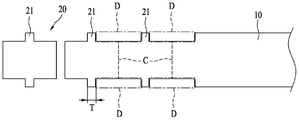
도 1은 본 발명에 따른 전극 커팅장치를 나타낸 개략도이고,
도 2는 본 발명의 전극 커팅장치에 의해 제조되는 전극과 전극시트를 나타낸 참고도이며,
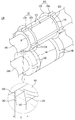
도 3은 본 발명에 따른 전극 커팅장치의 구성중 노칭유닛의 구조를 보여주는 요부사시도이고,
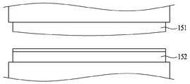
도 4는 본 발명에 따른 전극 커팅장치의 구성중 커팅유닛의 구조를 보여주는 요부측면도이며,
도 5 내지 도 7은 노칭유닛을 통해 전극시트에 노칭이 이루어지는 과정을 보여주는 공정도이다.1 is a schematic view showing an electrode cutting device according to the present invention,
2 is a reference view showing an electrode and an electrode sheet manufactured by the electrode cutting device of the present invention,
3 is a partial perspective view showing the structure of a notching unit in the configuration of the electrode cutting device according to the present invention;
4 is a main part side view showing the structure of a cutting unit in the configuration of the electrode cutting device according to the present invention;
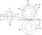
5 to 7 are process diagrams showing a process of notching the electrode sheet through the notching unit.
이하, 본 발명의 바람직한 실시 예들을 첨부된 도면을 참고하여 더욱 상세히 설명한다. 본 발명의 실시 예들은 여러 가지 형태로 변형될 수 있으며, 본 발명의 범위가 아래에서 설명하는 실시 예들에 한정되는 것으로 해석되어서는 안 된다. 본 실시 예들은 당해 발명이 속하는 기술 분야에서 통상의 지식을 가진 자에게 본 발명을 더욱 상세하게 설명하기 위해서 제공되는 것이다. 따라서 도면에 나타난 각 요소의 형상은 보다 분명한 설명을 강조하기 위하여 과장될 수 있다.Hereinafter, preferred embodiments of the present invention will be described in more detail with reference to the accompanying drawings. Embodiments of the present invention may be modified in various forms, and the scope of the present invention should not be construed as being limited to the embodiments described below. These embodiments are provided to explain the present invention in more detail to those of ordinary skill in the art to which the present invention pertains. Accordingly, the shape of each element shown in the drawings may be exaggerated to emphasize a clearer description.
제1, 제2 등의 용어는 다양한 구성요소들을 설명하는데 사용될 수 있지만, 구성요소들은 용어들에 의해 한정되어서는 안 된다. 용어들은 하나의 구성요소를 다른 구성요소로부터 구별하는 목적으로만 사용된다. Terms such as first, second, etc. may be used to describe various elements, but the elements should not be limited by the terms. The terms are used only for the purpose of distinguishing one component from another.
본 출원에서 사용한 용어는 단지 특정한 실시 예를 설명하기 위해 사용된 것으로, 본 발명을 한정하려는 의도가 아니다. 단수의 표현은 문맥상 명백하게 다르게 뜻하지 않는 한, 복수의 표현을 포함한다. 본 출원에서, "포함하다" 또는 "가지다" 등의 용어는 명세서상에 기재된 특징, 숫자, 단계, 동작, 구성요소, 부품 또는 이들을 조합한 것이 존재함을 지정하려는 것이지, 하나 또는 그 이상의 다른 특징들이나 숫자, 단계, 동작, 구성요소, 부품 또는 이들을 조합한 것들의 존재 또는 부가 가능성을 미리 배제하지 않는 것으로 이해되어야 한다.The terms used in the present application are only used to describe specific embodiments, and are not intended to limit the present invention. The singular expression includes the plural expression unless the context clearly dictates otherwise. In the present application, terms such as “comprise” or “have” are intended to designate that a feature, number, step, operation, component, part, or combination thereof described in the specification exists, but one or more other features It should be understood that this does not preclude the existence or addition of numbers, steps, operations, components, parts, or combinations thereof.
도 1은 본 발명에 따른 전극 커팅장치를 나타낸 개략도이고, 도 2는 본 발명의 전극 커팅장치에 의해 제조되는 전극과 전극시트를 나타낸 참고도이며, 도 3은 본 발명에 따른 전극 커팅장치의 구성중 노칭유닛의 구조를 보여주는 요부사시도이고, 도 4는 본 발명에 따른 전극 커팅장치의 구성중 커팅유닛의 구조를 보여주는 요부측면도이며, 도 5 내지 도 7은 노칭유닛을 통해 전극시트에 노칭이 이루어지는 과정을 보여주는 공정도이다.1 is a schematic diagram showing an electrode cutting device according to the present invention, FIG. 2 is a reference diagram showing an electrode and an electrode sheet manufactured by the electrode cutting device of the present invention, and FIG. 3 is a configuration of the electrode cutting device according to the present invention It is a major perspective view showing the structure of the middle notching unit, and FIG. 4 is a main side view showing the structure of the cutting unit among the components of the electrode cutting device according to the present invention, and FIGS. 5 to 7 are notched electrode sheets through the notching unit. This is a flowchart showing the process.
도 1 내지 도 7에 나타낸 바와 같이 본 발명의 전극 커팅장치(100)는, 공급되는 상기 전극시트(10)를 노칭과 커팅이 이루어질 수 있도록 가압하면서 이송시키는 적어도 하나의 이송부(110); 상기 전극시트(10)의 상하로 배열된 제1롤러(130)와 제2롤러(140)로 구성되어 상기 이송부(110)에 이웃하게 배치되며, 이송되는 상기 전극시트(10)의 폭방향 양측에 리드(21)를 성형하면서 연속적으로 노칭하는 노칭유닛(120); 및 상기 이송부(110)의 일측에 배치되며, 상기 리드가 성형된 상태로 노칭된 상기 전극시트(10)를 단일의 전극(20)으로 제조될 수 있도록 하는 커팅유닛(150);을 포함하여 구성된다.1 to 7, the
설명에 앞서, 본 발명 전극 커팅장치(100)의 가장 큰 특징은 전극시트(10) 의 노칭이 종래와 같은 프레스방식을 적용한 것이 아니라 롤러의 회전에 의해 가위 절단방식과 같이 점진적으로 오려지면서 절단되는 것에 있다.Prior to the description, the biggest feature of the
또한, 전극 커팅장치(100)의 후술하는 각 구성은 도시하지 않은 콘트롤러에 셋팅된 제어값에 의해 제어됨은 물론이다. In addition, each configuration to be described later of the
본 발명의 전극 커팅장치(100)는 단일의 공정라인 상에서 공급되는 전극활물질이 도포된 전극시트(10)의 노칭과 커팅이 순차적으로 이루어지도록 하여 단일의 전극(20)을 연속적으로 제조한다.The
전극 커팅장치(100)는 도 1에 도시된 바와 같이, 도면상 우측방향에서 좌측방향으로 전극시트(10)가 공급된다.As shown in FIG. 1 , the
이때, 전극시트(10)는 별도의 회전장치에 롤타입으로 거치되어 계속적인 공급이 이루어진다.At this time, the
전극시트(10)는 두 개의 이송부(110)에 의해 도면상 좌측방향으로 이송된다.The
이송부(110) 사이에는 이송되는 전극시트(10)를 노칭하는 노칭유닛(120)이 배치되어 있다.A
도면상 좌측에는 이송 간에 노칭유닛(120)을 통과하면서 노칭된 전극시트(10)를 단일의 전극(20)으로 제조하기 위해 전극시트(10)를 커팅하기 위한 커팅유닛(150)이 배치되어 있다.On the left side of the drawing, a
즉 전극 커팅장치(100)는, 이송되는 전극시트(10)를 일차적으로 노칭한 후 이차적으로 커팅하여 단일의 전극(20)을 연속적으로 제조하는 것이다.That is, the
한편, 도 2에는 후술하는 노칭유닛(120)에 의해 전극(20)의 폭방향 양측이 노칭된 노칭영역(D)이 도시되어 있으며, 이 노칭영역(D)은 이송되는 전극시트(10)에 계속적으로 가공된다.On the other hand, FIG. 2 shows a notched area D in which both sides of the
이하에서는 본 발명 전극 커팅장치(100)의 구조를 보다 상세히 설명하기로 한다.Hereinafter, the structure of the
이송부(110)는 외부로부터 공급되는 전극시트(10)를 후술하는 노칭유닛(120)과 커팅유닛(150)을 통해 순차적인 노칭과 커팅이 이루어질 수 있도록 전극시트(10)를 가압하면서 이송시킨다.The
이때, 이송부(110)는 도 1과 같이 이송부(110) 사이로 노칭유닛(120)이 배치될 수 있도록 두 개가 수평방향으로 이격되게 설치되는 것이 바람직하다.At this time, it is preferable that two
이 경우, 이송부(110)는 전극시트(10)의 길이방향을 따라 전극(20)의 상하면을 가압한 상태로 이송킬 수 있도록, 전극시트(10)의 상,하면에 밀착될 수 있는 복수개의 이송롤러로 구성되거나 또는 탄성을 갖는 벨트로 구성되는 이송컨베이어로 구성될 수 있다.In this case, the
본 실시예에서는 전극시트(10)의 상,하면과 면적촉을 높일수 있는 이송컨베이어로 구성된 것으로 도시하고 있으나, 그 구성을 반드시 한정하지 않는다.In the present embodiment, the upper and lower surfaces of the
따라서, 이송부(110)는 도 1과 같이 전극시트(10)를 밀착된 상태로 가압하면서 이송시키기 때문에 이송간 유동을 잡아줌으로써 노칭 및 커팅이 안정적으로 이루어지도로 한다.Therefore, since the
노칭유닛(120)은 도 1 및 도 3과 같이, 전극시트(10)를 사이에 두고 도면상 상하로 마주하게 배열된 제1롤러(130)와 제2롤러(140)로 구성된 상태로 두 개의 이송부(110)와 이웃하게 배치되며, 제1롤러(130)와 제2롤러(140)의 회전을 통해 이송되는 전극시트(10)의 폭방향 양측에 리드(21)를 성형하면서 연속적으로 노칭이 이루어지도록 한다.The notching
즉, 노칭유닛(120)은 후술하는 커팅유닛(150)에서 단일의 전극(20)을 제조할 수 있도록, 제1롤러(130)와 제2롤러(140)의 회전을 통해 전극시트(10)의 폭방향 양측에 연속적으로 리드(21)를 성형함과 동시에 노칭(도 2의 노칭영역 참조)이 이루어지도록 하는 것이다.That is, the notching
이를 위해, 이송되는 전극시트(10)의 도면상 상측에는 제1롤러(130)가 회전가능하게 배치되고, 제1롤러(130)와 대응하는 도면상 전극시트(10)의 하측으로는 제2롤러(140)가 회전가능하게 배치된다.To this end, a
이때, 제1롤러(130)와 제2롤러(140)는 각각 개별 회전을 위한 구동모터(M)가 구비되고, 각 구동모터(M)는 도시하지 않은 벨트 또는 풀리 등을 통해 제1롤러(130)와 제2롤러(140)를 회전시킨다.At this time, the
더하여, 제1롤러(130)는 전극시트(10)를 노칭하기 위해 하강할 수 있도록 실린더 또는 로봇이송장치 등의 구조를 갖는 승강장치(F)에 도 1에 도시된 바와 같이 구동모터(M)와 함께 고정되며, 이 승강장치(F)의 구동에 의해 제1롤러(130)가 노칭을 위한 하강을 하게 된다.In addition, the
그리고, 제1롤러(130)에는 도 3과 같이 제1롤러(130)의 길이방향을 따라 탈부착 가능하게 결합되며, 이송되는 전극시트(10)에 연속적인 노칭이 이루어질 수 있도록 등간격으로 배열된 4개의 성형지그(131)가 구비되어 있으며, 이에 대응하여 제2롤러(140)에는 후술하는 성형지그(131)의 성형커터(133) 단부가 수용되는 성형슬롯(142)이 형성된 가이드지그(141)가 각각 구비되어 있다.In addition, the
여기서, 제1롤러(130)에 등간격으로 배치된 성형지그(131)들 사이의 간격(T)은 제조되는 전극(20)의 리드(21)가 성형될 수 있는 간격(T)을 유지하는 것이 바람직하다. 정확하게는 도 3의 확대도와 같이 각 성형커터(133)의 리드성형커터(134) 사이의 간격(T)이 리드(21)가 성형될 수 있는 간격을 유지도록 함으로써, 전극시트(10)의 노칭이 이루어질 때 리드성형커터(134)에 의해 리드(21)가 성형될 수 있도록 하기 위함이다.Here, the interval (T) between the forming
한편, 제1롤러(130) 외주면에는 성형지그(131)가 수용된 상태로 도시하지 않은 별도의 고정수단에 의해 고정될 수 있도록 각 4개의 결합홈(B)이 형성되어 있으며, 가이드지그(141)는 제2롤러(140)의 양측으로 삽입되며 역시 별도의 고정수단에 의해 고정된다.On the other hand, on the outer peripheral surface of the
위와 같은 성형지그(131)와 가이드지그(141)는 각각 제1롤러(130)와 제2롤러(140)로부터 쉽게 결합 및 분리되는 구조를 이루기 때문에 성형지그(131)와 가이드지그(141)의 교체 및 유지보수가 용이하게 이루어질 수 있다.Since the forming
더하여, 4개의 성형지그(131)는 제1롤러(130) 및 제2롤러(140) 중 어느 하나의 롤러에 결합되고, 4개의 가이드지그(141)는 성형지그(131)들과 대향하는 위치로 다른 하나의 롤러에 결합될 수도 있다.In addition, the four forming
본실시예에서는 4개의 성형지그(131)가 제1롤러(130)에 결합되고, 4개의 가이드지그(141)가 제2롤러(140)에 결합된 것으로 도시하고 있으나, 그 위치는 반드시 한정하지 않는다.In this embodiment, four forming
한편, 성형지그(131)는 도 3과 같이 몸체(132)와 성형커터(133)로 구성된다.On the other hand, the forming
몸체(132)는 곡면으로 이루어진 소정의 면적과 전극시트(10)의 폭방향과 대응하는 길이를 유지하고 있으며, 제1롤러(130)의 결합홈(B)에 삽입되어 고정된다.The
성형커터(133)는, 몸체(132)의 길이방향 양단으로부터 각각 제1롤러(130)의 직경방향 외측을 향하여 돌출되며 이송되는 전극시트(10)의 폭방향 양측을 노칭함과 동시에 리드(21)를 성형하는 것으로, 대략적인 'ㄷ'자 형상을 갖는 리드성형커터(134)와 노칭커터(135)를 포함한다.The
여기서, 성형커터(133)의 외측 둘레는 도 3과 같이 전체적으로 곡률을 이루고 있는데, 이는 각 성형지그(131)에 형성된 4개의 성형커터(133))가 제1롤러(130)에 결합된 상태에서 동일한 원주를 이루도록 함으로써, 제1롤러(130)의 회전에 의한 성형커터(133)의 위치가 바뀌면서 전극시트(10)의 노칭이 계속적으로 이루어지도록 하기 위함이다.Here, the outer periphery of the forming
리드성형커터(134)는 두 개가 한조를 이루는 한 쌍으로 구성되며, 몸체(132)의 폭방향 곡률을 따라 소정거리 이격된 상태로 몸체(132)의 길이방향을 향하도록 돌출되게 형성되어 있다.The
이때, 리드성형커터(134)는 도 3과 같이 몸체(132)의 길이방향으로 형성됨에 따라, 제1롤러(130)의 회전에 의해 성형커터(133)의 노칭이 이루어질 때 리드(21)의 일측과 타측을 순차적으로 노칭함으로써 리드(21)를 성형하게 된다(도 7 참조). At this time, as the
노칭커터(135)는 도 3과 같이 두 개의 리드성형커터(134)의 일측을 연결하는 것으로, 전극시트(10)로부터 리드(21)를 제외한 영역의 노칭이 이루어지도록 한다.The notching
정확하게는, 노칭커터(135)가 두 개의 리드성형커터(134)를 연결하여 'ㄷ'자 형상을 갖는 단일의 형상을 이룰수 있도록 함으로써, 도 2에 도시된 바와 같이 전극시트(10)의 폭방향 양측(도면상 상측과 하측)의 노칭영역(D)이 노칭될 수 있도록 하는 것이다.Precisely, the
여기서, 리드성형커터(134) 및 노칭커터(135)는 제1롤러(130)의 회전에 의해 전극시트(10)의 노칭영역(D)을 노칭할 수 있도록 말단부가 예민한 커터로 형성됨은 물론이다.Here, the
따라서, 복수개의 성형커터(133)들은 회전을 통해 이송되는 전극시트(10)의 폭방향 양측의 노칭영역(D)을 순차적으로 노칭하고, 리드성형커터(134)의 노칭에 의해 노칭영역(D)과 노칭영역(D) 사이로 리드(21)가 성형될 수 있도록 한다.Accordingly, the plurality of shaping
가이드지그(141)는 원통 형상을 이룬 상태로 이송되는 전극시트(10)의 하면과 접촉되며, 성형커터(133)가 배치된 위치와 대응되게 제2롤러(140)의 양측으로 삽입되어 결합된다. The
가이드지그(141)에는 성형커터(133)와 대응하는 'ㄷ'자 형상의 성형슬롯(142) 4개가 외주면을 따라 형성되어 있다.In the
이때, 성형슬롯(142)은 성형커터(133) 즉 리드성형커터(134)와 노칭커터(135)의 단부가 도 3의 확대도와 같이 수용되어 맞물림이 이루어질 수 있도록 제2롤러(140)를 향하는 홈으로 형성된다.At this time, the forming
따라서, 가이드지그(141)는 성형슬롯(142)을 성형커터(133)와 동일 선상을 이루도록 하여 전극시트(10)의 노칭이 이루어질 때 성형슬롯(142)과 성형커터(133)의 단부를 맞물려 전극시트(10)의 안정적인 노칭이 이루어지도록 한다.Therefore, the
또한, 가이드지그(141)는 전극시트(10) 하면과 접촉된 상태임에 따라 전극시트(10)의 노칭시 전극시트(10)의 하면을 안정적으로 지지함으로써, 노칭을 위한 성형커터(133)의 압력이 작용될 때 전극시트(10)가 하측방향으로 처지는 것을 원천적으로 방지한다.In addition, the
따라서, 노칭유닛(120)은 제1,2롤러(130,140)의 회전을 통한 성형커터(133)와 성형슬롯(142)에 의해 전극시트(10)의 노칭영역(D)이 가위 절단방식과 같이 점진적으로 오려지면서 절단되도록 함으로써, 전극시트에 도포된 전극활물질의 크랙 및 깨짐을 방지하고, 더하여 분진의 발생을 최대한 억제하게 된다.Accordingly, in the notching
본 실시예에서는 성형슬롯(142)이 가이드지그(141)에 형성된 것으로 도시하고 있으나, 제2롤러(140)의 외주면에 직접 형성될 수도 있기 때문에 성형슬롯(142)의 형성 위치는 한정하지 않는다. In this embodiment, although the forming
또한, 본 실시예에서는 성형지그(131)와 성형슬롯(142)이 각각 4개인 것으로 도시하고 있으나, 그 개수는 전극의 길이에 따라 달라질 수 있기 때문에 반드시 한정하지 않는다.In addition, although the present embodiment shows that the forming
커팅유닛(150)은 도 1과 같이 도면상 좌측의 이송부(110)의 일측으로 배치되며, 노칭유닛(120)을 통해 도 2와 같이 리드(21)가 성형된 상태로 노칭이 완료된 전극시트(10)를 단일의 전극(20)으로 제조될 수 있도록 설정된 커팅라인(C)를 커팅한다.The
커팅유닛(150)은 전극시트(10)를 사이에 두고 상하에서 승강 가능하게 배치된 상부커터(151)와 하부커터(152)로 구성된다.The
이때, 상부커터(151)와 하부커터(152)의 칼날은 서로 엇갈리게 배열된 것이 바람직한데, 이는 도 1과 같이 상부커터(151)와 하부커터(152)의 칼날 경사면이 서로 반대하는 방향을 향하도록 함으로써 전극시트(10)의 정교한 커팅이 이루어지도록 하기 위함이다.At this time, it is preferable that the blades of the
또한, 상부커터(151)와 하부커터(152)는 전극시트(10)의 커팅을 위해 각각 승강할 수 있도록 실린더 또는 로봇이송장치 등의 구조를 갖는 승강장치(F)에 도 1과 같이 고정된다.In addition, the
한편, 상부커터(151)의 하측 단부의 칼날은 도 4와 같이 길이방향 양측에서 중심으로 향할수록 하측으로 만곡지게 형성되고, 하부커터(152)의 상측 단부의 칼날은 수평으로 형성된 것이 바람직한데, 이는 전극시트(10)의 하부에 수평의 하부커터(152)가 배치되도록한 상태에서 하강하는 상부커터(151)의 칼날이 전극시트(10)의 중심으로부터 외측방향으로 향할수록 점진적으로 절단되도록 하여 종래와 같은 프레스방식의 충격이 전극시트(10)로 전달되는 것을 방지하기 위함이다.On the other hand, the blade of the lower end of the
따라서, 커팅유닛(150)은 상부커터(151)와 하부커터(152)의 칼날이 서로 엇갈리게 배열된 상태에서 칼날과 칼날이 교차하는 가위질과 같은 방식으로 점진적인 커팅이 이루어지기 때문에 전극시트(10)의 안정적인 커팅이 담보된다.Therefore, in the
본 실시예에서는 상부커터(151)의 칼날이 만곡진 것으로 도시하고 있으나, 상부커터(151)와 하부커터(152)의 칼날이 서로 엇갈리게 배열된 것이라면 만곡된 칼날의 형상 및 위치 등은 한정하지 않는다.In this embodiment, although the blade of the
이하, 첨부된 도면들을 참조하여 본 발명에 따른 전극 커팅장치(100)를 이용하여전극(20)을 제조하는 과정을 설명하면 다음과 같다.Hereinafter, a process of manufacturing the
먼저, 권취된 띠 형상의 전극시트(10)가 도 1과 같이 도면상 우측에 배치된 이송부(110)를 통해 도면상 좌측으로 공급된다.First, the wound strip-shaped
이때, 노칭유닛(120)의 제1롤러(130)와 제2롤러(140)는 이송되는 전극시트(10)와 함께 회전하게 되며, 제1롤러(130)의 성형커터(133)와 제2롤러(140)의 가이드지그(141)의 회전주기는 동일하게 이루어진다. 즉, 성형커터(133)와 가이드지그(141)가 마주하는 타이밍이 전극시트(10)를 사이에 두고 일치되게 이루어지는 것이다.At this time, the
또한, 성형커터(133)의 단부가 가이드지그(141)의 성형슬롯(142)에 수용되는 것이 이송되는 전극시트(10) 양측의 폭방향 양측이 노칭되는 시점이며, 이를 위해 제1,2롤러(130,140)의 회전과 전극시트(10)의 이송속도는 도시한지 않은 콘트롤러에 의해 제어된다.In addition, the end of the forming
먼저, 초기의 전극 커팅장치(100)는 도 1과 같이 커팅유닛(150)의 상부커터(151)와 하부커터(152)는 승강장치(F)에 의해 서로 이격된 상태이고, 제1롤러(130)는 이송되는 전극시트(10)의 상부면으로부터 소정간격으로 이격된 상태로 제2롤러(140)와 동일한 속도로 회전하며, 제2롤러(140)는 전극시트(10) 하면과 접촉된 채로 회전하는 상태이다.First, in the initial
위와 같은 상태에서 도 5와 같이 전극시트(10)의 이송이 이루어지면서 제1롤러(130)가 하강하게 된다.In the above state, as shown in FIG. 5 , the
제1롤러(130)의 하강은 도 6과 같이 성형커터(133)의 노칭커터(135) 단부가 성형슬롯(142)의 홈으로 일부 삽입될 때까지 이루어지게 되고, 이 과정에서 노칭커터(135) 단부는 전극시트(10)를 절단하면서 성형슬롯(142)의 홈으로 수용된다.The lowering of the
이때, 제1롤러(130)와 제2롤러(140)는 동일한 속도로 회전하고 있는 상태이다.At this time, the
도 6과 같이 노칭커터(135) 단부가 성형슬롯(142)의 홈으로 수용되면, 제1롤러(130)와 제2롤러(140)의 계속적인 회전과 전극시트(10)의 도면상 좌측방향으로의 이송에 따라 전극시트(10)의 폭방향 양측의 노칭이 시작된다.When the end of the notching
제1롤러(130)와 제2롤러(140)의 계속적인 회전에 의해 노칭커터(135)의 노칭은 계속적으로 이루어지고, 어느 순간 도 7과 같이 리드성형커터(134)가 리드(21)의 일측을 노칭함으로써, 전극시트(10) 폭방향 양측의 노칭을 완료된다.The notching of the notching
이후, 계속되는 제1롤러(130)와 제2롤러(140)의 회전에 의해 인접한 성형커터(133)의 리드성형커터(134)가 리드(21)의 타측을 노칭하여 리드(21)를 성형하면서 노칭커터(135)의 노칭을 통해 전극시트(10)의 폭방향 양측에 계속적으로 리드(21)를 성형하면서 도 2와 같이 노칭영역(D)을 노칭해 나간다.Thereafter, the
노칭유닛(130)을 통해 노칭공정이 완료된 전극시트(10)는 계속되는 이송에 의해 커팅유닛(150)에 도달하게 되고, 이때 전극시트(10)의 커팅라인(C)이 상부커터(151)와 하부커터(152)의 직하방에 위치하게 된다.The
하부커터(152)는 승강장치(F)에 의해 상승하면서 하부커터(152)의 칼날을 전극시트(10) 커팅라인(C)의 하면에 밀착시킨다.As the
이후, 상부커터(151)가 승강장치(F)에 의해 하강하면서 전극시트(10)의 커팅라인(C)을 커팅하여 단일의 전극(20)을 제조를 하게 되고, 이러한 커팅공정은 전극시트(10)의 이송속도에 맞춰 계속적으로 이루어진다.Thereafter, while the
지금까지 서술된 바와 같이 본 발명의 이차전지용 전극 커팅장치는, 전극을 제조하기 위한 전극시트의 노칭이 롤러의 회전에 의해 점진적으로 절단 되도록 함으로써 전극시트에 도포된 전극활물질의 크랙 및 깨짐을 방지함과 동시에 분진의 발생을 억제하고, 하나의 공정라인에서 전극시트의 노칭과 커팅이 연속적으로 이루어질 수 있도록 하여 생산성을 향상시키는 탁월한 효과가 있다.As described so far, the electrode cutting device for a secondary battery of the present invention prevents cracks and cracks of the electrode active material applied to the electrode sheet by allowing the notching of the electrode sheet for manufacturing the electrode to be cut gradually by the rotation of the roller. At the same time, it suppresses the generation of dust, and it has an excellent effect of improving productivity by allowing notching and cutting of the electrode sheet to be continuously performed in one process line.
또한, 노칭유닛의 제1롤러와 제2롤러에 구비된 성형커터와 가이드지그의 교체가 가능함에 따라 상시적인 유지보수가 가능한 기술적 효과 또한 탁월하다.In addition, as the forming cutter and guide jig provided on the first and second rollers of the notching unit can be replaced, the technical effect of enabling constant maintenance is also excellent.
이상, 본 발명의 이차전지용 전극 커팅장치를 바람직한 실시예 및 첨부된 도면에 의해 설명하였으나, 이는 발명의 이해를 돕고자 하는 것일 뿐 발명의 기술적 범위를 이에 한정하고자 함이 아님은 물론이다.As described above, the electrode cutting device for a secondary battery of the present invention has been described with reference to the preferred embodiment and the accompanying drawings, but it goes without saying that this is only intended to help the understanding of the present invention and is not intended to limit the technical scope of the present invention.
즉, 본 발명의 기술적 요지를 벗어나지 않고도 당해 발명이 속하는 기술 분야에서 통상의 지식을 가진 자라면 다양한 변형이나 개조가 가능함은 물론이고, 그와 같은 변경이나 개조는 청구범위의 해석상 본 발명의 기술적 범위 내에 있음은 말할 나위가 없다.That is, without departing from the technical gist of the present invention, various modifications and alterations are possible by those skilled in the art to which the present invention pertains. It goes without saying that it is within.
10 : 전극시트
20 : 전극
21 : 리드
100 : 전극 커팅장치
110 : 이송부
120 : 노칭유닛
130 : 제1롤러
131 : 성형지그
132 : 몸체
133 : 성형커터
134 : 리드성형커터
135 : 노칭커터
140 : 제2롤러
141 : 가이드지그
142 : 삽입슬롯
150 : 커팅유닛
151 : 상부커터
152 : 하부커터
B : 결합홈
C : 커팅라인
D : 노칭영역
F : 승강장치
M : 구동모터
T : 간격10: electrode sheet 20: electrode
21: lead 100: electrode cutting device
110: transfer unit 120: notching unit
130: first roller 131: forming jig
132: body 133: molding cutter
134: lead molding cutter 135: notching cutter
140: second roller 141: guide jig
142: insertion slot 150: cutting unit
151: upper cutter 152: lower cutter
B : coupling groove C : cutting line
D : Notching area F : Elevating device
M : drive motor T : gap
Claims (9)
공급되는 상기 전극시트(10)를 노칭과 커팅이 이루어질 수 있도록 가압하면서 이송시키는 적어도 하나의 이송부(110);
상기 전극시트(10)의 상하로 배열된 제1롤러(130)와 제2롤러(140)로 구성되어 상기 이송부(110)에 이웃하게 배치되며, 이송되는 상기 전극시트(10)의 폭방향 양측에 리드(21)를 성형하면서 연속적으로 노칭하는 노칭유닛(120); 및
상기 이송부(110)의 일측에 배치되며, 상기 리드가 성형된 상태로 노칭된 상기 전극시트(10)를 단일의 전극(20)으로 제조될 수 있도록 하는 커팅유닛(150);을 포함하여 구성된 것을 특징으로 하는 이차전지용 전극 커팅장치.
In the electrode cutting device 100 for a secondary battery for manufacturing a single electrode 20 from the transferred electrode sheet 10,
at least one transfer unit 110 for transferring the supplied electrode sheet 10 while pressing it so that notching and cutting can be performed;
It is composed of a first roller 130 and a second roller 140 arranged vertically of the electrode sheet 10 and is disposed adjacent to the transfer unit 110, both sides in the width direction of the transferred electrode sheet 10. A notching unit 120 for continuously notching while forming the lead 21; and
A cutting unit 150 disposed on one side of the transfer unit 110 and configured to allow the electrode sheet 10 notched in a molded state to be manufactured as a single electrode 20; Electrode cutting device for secondary batteries, characterized in that.
상기 제1롤러(130)와 제2롤러(140)에는 각각 탈부착 가능하게 결합되며, 이송되는 상기 전극시트(10)에 연속적인 노칭이 이루어질 수 있도록 복수개의 성형지그(131)와 가이드지그(141)가 구비된 것을 특징으로 하는 이차전지용 전극 커팅장치.
According to claim 1,
A plurality of forming jigs 131 and guide jigs 141 are respectively detachably coupled to the first roller 130 and the second roller 140 so that continuous notching can be made on the transferred electrode sheet 10 . ) electrode cutting device for secondary batteries, characterized in that it is provided.
상기 제1롤러(130) 및 제2롤러(140) 중 어느 하나의 롤러에는 상기 전극시트(10) 노칭시 리드(21)가 성형될 수 있는 간격이 유지되도록 상기 성형지그(131)가 등간격으로 결합되고, 다른 하나의 롤러에는 상기 가이드지그(141)가 결합된 것을 특징으로 하는 이차전지용 전극 커팅장치.
3. The method of claim 2,
The forming jig 131 is equally spaced on any one of the first roller 130 and the second roller 140 so that a gap at which the lead 21 can be formed is maintained when the electrode sheet 10 is notched. The electrode cutting device for secondary batteries, characterized in that the guide jig 141 is coupled to the other roller.
상기 성형지그(131)는, 소정의 길이를 갖는 몸체(132)와, 상기 몸체(132)의 양단으로부터 각각 돌출되어 상기 전극시트(10)의 폭방향 양측을 노칭하는 성형커터(133),를 포함하며,
상기 성형커터(133)는,
상기 몸체(132)의 폭방향 곡률을 따라 이격되게 형성되며, 성형되는 상기 리드(21)의 일측과 타측을 노칭하는 한 쌍의 리드성형커터(134)와,
상기 리드성형커터(134)들의 일측을 연결하며, 상기 전극시트(10)로부터 리드를 제외한 영역을 노칭하는 노칭커터(135),로 구성된 것을 특징으로 하는 이차전지용 전극 커팅장치.
3. The method of claim 2,
The forming jig 131 includes a body 132 having a predetermined length, and a forming cutter 133 protruding from both ends of the body 132 and notching both sides of the electrode sheet 10 in the width direction. includes,
The molding cutter 133,
A pair of lead molding cutters 134 formed to be spaced apart along the width direction curvature of the body 132 and notching one side and the other side of the lead 21 to be molded;
A notch cutter (135) for connecting one side of the lead forming cutters (134) and notching an area excluding the lead from the electrode sheet (10), an electrode cutting device for a secondary battery.
상기 가이드지그(141)의 외주면에는, 상기 성형커터(133)와 대응하는 형상으로 상기 성형커터(133)의 단부가 수용될 수 있도록 홈으로 이루어진 복수개의 성형슬롯(142)이 형성된 것을 특징으로 하는 이차전지용 전극 커팅장치.
5. The method of claim 4,
On the outer peripheral surface of the guide jig 141, a plurality of forming slots 142 made of grooves to accommodate the end of the forming cutter 133 in a shape corresponding to the forming cutter 133 is formed, characterized in that Electrode cutting device for secondary batteries.
상기 제1롤러(130)는 상기 전극시트(10)를 노칭하기 위해 승강하는 것을 특징으로 하는 이차전지용 전극(20)판 커팅장치.
According to claim 1,
The first roller 130 is an electrode (20) plate cutting device for a secondary battery, characterized in that the lifting in order to notch the electrode sheet (10).
커팅유닛(150)은, 상기 전극시트(10)를 사이에 두고 상하에서 승강 가능하게 배치된 상부커터(151)와 하부커터(152)로 구성되며, 상기 상부커터(151)와 하부커터(152)의 칼날은 서로 엇갈리게 배열된 것을 특징으로 하는 이차전지용 전극 커팅장치.
According to claim 1,
The cutting unit 150 is composed of an upper cutter 151 and a lower cutter 152 arranged so as to be liftable from the top and bottom with the electrode sheet 10 interposed therebetween, the upper cutter 151 and the lower cutter 152 . ) of an electrode cutting device for secondary batteries, characterized in that the blades are alternately arranged.
상기 상부커터(151)의 하측 단부는 길이방향 양측에서 중심으로 향할수록 하측으로 만곡지게 형성되고, 상기 하부커터(152)의 상측 단부는 수평으로 형성된 것을 특징으로 하는 이차전지용 전극 커팅장치.
8. The method of claim 7,
The lower end of the upper cutter (151) is formed to be curved downward toward the center from both sides in the longitudinal direction, and the upper end of the lower cutter (152) is formed horizontally.
상기 이송부(110)는 상기 전극시트(10)의 길이방향을 따라 전극(20)의 상하면을 가압한 상태로 이송시키는 복수개의 이송롤러 또는 이송컨베이어 인 것을 특징으로 하는 이차전지용 극판 커팅장치.According to claim 1,
The transfer unit 110 is an electrode plate cutting device for a secondary battery, characterized in that it is a plurality of transfer rollers or transfer conveyors for transferring the upper and lower surfaces of the electrode 20 in a pressurized state along the longitudinal direction of the electrode sheet (10).
Priority Applications (1)
| Application Number | Priority Date | Filing Date | Title |
|---|---|---|---|
| KR1020200018238A KR102300705B1 (en) | 2020-02-14 | 2020-02-14 | Electrode cutting apparatus for secondary battery |
Applications Claiming Priority (1)
| Application Number | Priority Date | Filing Date | Title |
|---|---|---|---|
| KR1020200018238A KR102300705B1 (en) | 2020-02-14 | 2020-02-14 | Electrode cutting apparatus for secondary battery |
Publications (2)
| Publication Number | Publication Date |
|---|---|
| KR20210103719A true KR20210103719A (en) | 2021-08-24 |
| KR102300705B1 KR102300705B1 (en) | 2021-09-10 |
Family
ID=77506878
Family Applications (1)
| Application Number | Title | Priority Date | Filing Date |
|---|---|---|---|
| KR1020200018238A KR102300705B1 (en) | 2020-02-14 | 2020-02-14 | Electrode cutting apparatus for secondary battery |
Country Status (1)
| Country | Link |
|---|---|
| KR (1) | KR102300705B1 (en) |
Cited By (1)
| Publication number | Priority date | Publication date | Assignee | Title |
|---|---|---|---|---|
| CN114833401A (en) * | 2022-04-19 | 2022-08-02 | 三一技术装备有限公司 | Pole piece roller, roller cutting mechanism and pole piece roller cutting method |
Citations (6)
| Publication number | Priority date | Publication date | Assignee | Title |
|---|---|---|---|---|
| JP2001266857A (en) * | 2000-03-22 | 2001-09-28 | Toyota Motor Corp | Manufacturing method of battery electrode and manufacturing device |
| KR20120060704A (en) | 2010-12-02 | 2012-06-12 | 주식회사 엘지화학 | Novel Device for Cutting Electrode Sheet and Secondary Battery Manufactured Using the Same |
| KR20120060706A (en) | 2010-12-02 | 2012-06-12 | 주식회사 엘지화학 | Novel Device for Notching and Secondary Battery Manufactured Using the Same |
| KR20150004557A (en) * | 2013-07-03 | 2015-01-13 | 주식회사 엠플러스 | Secondary battery electrode deviation correction apparatus |
| KR20170048757A (en) * | 2015-10-27 | 2017-05-10 | 주식회사 엘지화학 | Device for Manufacturing Electrode Comprising Notching Roller |
| JP2017196669A (en) * | 2016-04-25 | 2017-11-02 | 株式会社豊田自動織機 | Electrode manufacturing facility |
-
2020
- 2020-02-14 KR KR1020200018238A patent/KR102300705B1/en active IP Right Grant
Patent Citations (6)
| Publication number | Priority date | Publication date | Assignee | Title |
|---|---|---|---|---|
| JP2001266857A (en) * | 2000-03-22 | 2001-09-28 | Toyota Motor Corp | Manufacturing method of battery electrode and manufacturing device |
| KR20120060704A (en) | 2010-12-02 | 2012-06-12 | 주식회사 엘지화학 | Novel Device for Cutting Electrode Sheet and Secondary Battery Manufactured Using the Same |
| KR20120060706A (en) | 2010-12-02 | 2012-06-12 | 주식회사 엘지화학 | Novel Device for Notching and Secondary Battery Manufactured Using the Same |
| KR20150004557A (en) * | 2013-07-03 | 2015-01-13 | 주식회사 엠플러스 | Secondary battery electrode deviation correction apparatus |
| KR20170048757A (en) * | 2015-10-27 | 2017-05-10 | 주식회사 엘지화학 | Device for Manufacturing Electrode Comprising Notching Roller |
| JP2017196669A (en) * | 2016-04-25 | 2017-11-02 | 株式会社豊田自動織機 | Electrode manufacturing facility |
Cited By (1)
| Publication number | Priority date | Publication date | Assignee | Title |
|---|---|---|---|---|
| CN114833401A (en) * | 2022-04-19 | 2022-08-02 | 三一技术装备有限公司 | Pole piece roller, roller cutting mechanism and pole piece roller cutting method |
Also Published As
| Publication number | Publication date |
|---|---|
| KR102300705B1 (en) | 2021-09-10 |
Similar Documents
| Publication | Publication Date | Title |
|---|---|---|
| CN109004260B (en) | Preparation method of cutting lamination winding type flexible package lithium ion battery cell | |
| KR102182307B1 (en) | Device for Manufacturing Electrode Comprising Pattern Zig and Scrap Outlet Portion | |
| KR102026126B1 (en) | Device for Manufacturing Electrode Comprising Notching Roller | |
| KR20180133235A (en) | Manufacturing system and method for electrode assembly | |
| CN105742688A (en) | Device for automatically winding wound laminated battery | |
| KR102300705B1 (en) | Electrode cutting apparatus for secondary battery | |
| CN114976188A (en) | Circulating type multi-station laminated battery cell circulation production line | |
| KR20140029808A (en) | Winding apparatus for electrode assembly | |
| US6997228B2 (en) | Lamination apparatus for automated manufacturing system of lithium secondary battery | |
| CN105932339A (en) | Fast preparation method of wound lithium-ion laminated battery | |
| EP4050688A1 (en) | Apparatus and method for improving foldability of separator in prismatic secondary battery cell manufacturing equipment | |
| KR101873198B1 (en) | Apparatus For Connecting Meterial Of Rechargeable Battery | |
| KR20220012615A (en) | Apparatus for taping battery cell | |
| CN217009271U (en) | Laminating device for secondary battery | |
| KR102389191B1 (en) | Battery pack manufacturing devide and manufacturing method of battery pack | |
| CN108028351B (en) | Secondary battery electrode manufacturing apparatus including electrode mixture layer forming mold | |
| KR102476548B1 (en) | Conveyor for manufacturing battery cell | |
| KR102285417B1 (en) | Manufacturing apparatus for pocketing positive electrode used in battery | |
| KR20210150896A (en) | The Apparatus And The Method For Manufacturing Electrode Assembly | |
| KR20210144311A (en) | The Electrode, The Secondary Battery, The Apparatus And The Method For Manufacturing Electrode | |
| KR20210125281A (en) | The Apparatus And The Method For Manufacturing Electrode | |
| CN217485522U (en) | Circulating type multi-station laminated battery cell circulation production line | |
| CN217848033U (en) | Circulating type multi-station battery core lamination production line | |
| KR20210063843A (en) | The Slitter | |
| KR102629066B1 (en) | Brushing method and apparatus |
Legal Events
| Date | Code | Title | Description |
|---|---|---|---|
| E701 | Decision to grant or registration of patent right | ||
| GRNT | Written decision to grant |