KR20210098870A - Weaving method, weft selector for implementing such a method and weaving loom incorporating such a weft selector - Google Patents
Weaving method, weft selector for implementing such a method and weaving loom incorporating such a weft selector Download PDFInfo
- Publication number
- KR20210098870A KR20210098870A KR1020210014390A KR20210014390A KR20210098870A KR 20210098870 A KR20210098870 A KR 20210098870A KR 1020210014390 A KR1020210014390 A KR 1020210014390A KR 20210014390 A KR20210014390 A KR 20210014390A KR 20210098870 A KR20210098870 A KR 20210098870A
- Authority
- KR
- South Korea
- Prior art keywords
- weft
- clamp
- selector
- along
- gripper
- Prior art date
Links
Images


Classifications
-
- D—TEXTILES; PAPER
- D03—WEAVING
- D03D—WOVEN FABRICS; METHODS OF WEAVING; LOOMS
- D03D47/00—Looms in which bulk supply of weft does not pass through shed, e.g. shuttleless looms, gripper shuttle looms, dummy shuttle looms
- D03D47/12—Looms in which bulk supply of weft does not pass through shed, e.g. shuttleless looms, gripper shuttle looms, dummy shuttle looms wherein single picks of weft thread are inserted, i.e. with shedding between each pick
- D03D47/125—Weft holding devices
-
- D—TEXTILES; PAPER
- D03—WEAVING
- D03D—WOVEN FABRICS; METHODS OF WEAVING; LOOMS
- D03D47/00—Looms in which bulk supply of weft does not pass through shed, e.g. shuttleless looms, gripper shuttle looms, dummy shuttle looms
- D03D47/34—Handling the weft between bulk storage and weft-inserting means
-
- D—TEXTILES; PAPER
- D03—WEAVING
- D03D—WOVEN FABRICS; METHODS OF WEAVING; LOOMS
- D03D49/00—Details or constructional features not specially adapted for looms of a particular type
- D03D49/24—Mechanisms for inserting shuttle in shed
- D03D49/50—Miscellaneous devices or arrangements concerning insertion of weft and not otherwise provided for
-
- D—TEXTILES; PAPER
- D03—WEAVING
- D03D—WOVEN FABRICS; METHODS OF WEAVING; LOOMS
- D03D47/00—Looms in which bulk supply of weft does not pass through shed, e.g. shuttleless looms, gripper shuttle looms, dummy shuttle looms
- D03D47/34—Handling the weft between bulk storage and weft-inserting means
- D03D47/38—Weft pattern mechanisms
-
- D—TEXTILES; PAPER
- D03—WEAVING
- D03C—SHEDDING MECHANISMS; PATTERN CARDS OR CHAINS; PUNCHING OF CARDS; DESIGNING PATTERNS
- D03C9/00—Healds; Heald frames
- D03C9/02—Healds
-
- D—TEXTILES; PAPER
- D03—WEAVING
- D03D—WOVEN FABRICS; METHODS OF WEAVING; LOOMS
- D03D41/00—Looms not otherwise provided for, e.g. for weaving chenille yarn; Details peculiar to these looms
- D03D41/004—Looms for three-dimensional fabrics
-
- D—TEXTILES; PAPER
- D03—WEAVING
- D03D—WOVEN FABRICS; METHODS OF WEAVING; LOOMS
- D03D47/00—Looms in which bulk supply of weft does not pass through shed, e.g. shuttleless looms, gripper shuttle looms, dummy shuttle looms
- D03D47/12—Looms in which bulk supply of weft does not pass through shed, e.g. shuttleless looms, gripper shuttle looms, dummy shuttle looms wherein single picks of weft thread are inserted, i.e. with shedding between each pick
- D03D47/20—Constructional features of the thread-engaging device on the inserters
- D03D47/23—Thread grippers
-
- D—TEXTILES; PAPER
- D03—WEAVING
- D03D—WOVEN FABRICS; METHODS OF WEAVING; LOOMS
- D03D47/00—Looms in which bulk supply of weft does not pass through shed, e.g. shuttleless looms, gripper shuttle looms, dummy shuttle looms
- D03D47/27—Drive or guide mechanisms for weft inserting
- D03D47/271—Rapiers
-
- D—TEXTILES; PAPER
- D03—WEAVING
- D03D—WOVEN FABRICS; METHODS OF WEAVING; LOOMS
- D03D47/00—Looms in which bulk supply of weft does not pass through shed, e.g. shuttleless looms, gripper shuttle looms, dummy shuttle looms
- D03D47/27—Drive or guide mechanisms for weft inserting
- D03D47/275—Drive mechanisms
-
- D—TEXTILES; PAPER
- D03—WEAVING
- D03D—WOVEN FABRICS; METHODS OF WEAVING; LOOMS
- D03D47/00—Looms in which bulk supply of weft does not pass through shed, e.g. shuttleless looms, gripper shuttle looms, dummy shuttle looms
- D03D47/34—Handling the weft between bulk storage and weft-inserting means
- D03D47/36—Measuring and cutting the weft
-
- D—TEXTILES; PAPER
- D03—WEAVING
- D03D—WOVEN FABRICS; METHODS OF WEAVING; LOOMS
- D03D49/00—Details or constructional features not specially adapted for looms of a particular type
- D03D49/70—Devices for cutting weft threads
-
- D—TEXTILES; PAPER
- D03—WEAVING
- D03J—AUXILIARY WEAVING APPARATUS; WEAVERS' TOOLS; SHUTTLES
- D03J1/00—Auxiliary apparatus combined with or associated with looms
- D03J1/04—Auxiliary apparatus combined with or associated with looms for treating weft
Abstract
Description
본 발명은 제직기에서 경사들 및 제직 위사들로 직물을 제직하는 방법에 관한 것이다. 본 발명은 또한, 이러한 방법을 구현하도록 하는 위사 선택기, 및 무엇보다도 이러한 위사 선택기를 포함하는 제직기에 관한 것이다.The present invention relates to a method for weaving a fabric with warps and weft yarns on a weaving machine. The invention also relates to a weft selector which makes it possible to implement such a method, and above all to a weaving machine comprising such a weft selector.
본 발명의 기술 분야는 2차원 또는 3차원 직물의 제직 분야로, 다양한 위사들, 예를 들어, 다양한 탄소 원사들(carbon yarns)은 다중 위사 선택기(multi-weft selector) 덕분에 제직된다.The technical field of the present invention is the field of weaving of two-dimensional or three-dimensional fabrics, wherein various weft yarns, for example various carbon yarns, are woven thanks to a multi-weft selector.
EP-A-3 121317로부터 위사의 길이를 조절할 수 있는 공정을 사용하여 다양한 크기의 탄소 위사들을 제직하는 방법이 알려져 있다. 이것은 위사 재료의 과소비를 방지한다. 위사 전달 유닛이 제공된다. 이의 구조는 다음 위입(pick)에 사용할 위사를 쉽게 선택하는 것을 허용하지 않는다.It is known from EP-A-3 121317 a method for weaving carbon weft yarns of various sizes using a process capable of controlling the length of the weft yarns. This prevents overconsumption of the weft material. A weft transfer unit is provided. Its structure does not allow easy selection of the weft to use for the next pick.
반면에, US-A-2012/0125476은 두 개의 다른 위사 재료들 중 하나를 개구(shed)에 삽입하기 위해 두 개의 회전 암(swivel arms)의 회전 운동을 사용하는 방법을 개시한다. 이 회전 운동은 상대적으로 부정확한다. 이 접근법은 두 개의 서로 다른 위 사들로만 제한된다. 위사 재료의 단부(extremity)는 절단 후 느슨해져서 짧은 길이로 회전 유닛에서 돌출하므로, 삽입 레이피어(rapier)의 그리퍼(gripper)가 놓칠 수 있다. 또한, 이 장치에서는, 모터가 각각의 회전 유닛마다 필요하며, 비싸고 부피가 크다. 더욱이, 테이프는 통상적으로, 다소 오목할 수 있는 특정 클램프 형상 덕분에, 그것의 주축 주위로 구부러져, 그것의 단부에 강성(stiffness)을 가져 오는데, 이는 부정확(imprecise)하고, 보편적(universal)이지 않다.On the other hand, US-A-2012/0125476 discloses a method using the rotational motion of two swivel arms to insert one of the two different weft yarn materials into the shed. This rotational motion is relatively inaccurate. This approach is limited to only two different weft yarns. The extremity of the weft material loosens after cutting and protrudes from the rotating unit for a short length, so that the gripper of the insert rapier may miss. Also, in this device, a motor is required for each rotating unit, and is expensive and bulky. Moreover, the tape typically bends around its main axis, thanks to a specific clamp shape, which may be somewhat concave, resulting in stiffness at its ends, which is imprecise and not universal. .
또한 DE-A-2531954로부터 알려진 바와 같이, 일부 위사들을 제직기의 개구 내로 인입시키기 위해 여러 선택기들이 제공되는 위사 선택 장치를 사용한다. 이 위사 선택 장치의 문제점은, 공급 장치가 위사 방향으로 전진 이동하고 위사를 취하도록 적합화(adapted)되지 않는다는 점이다. 추가적으로, 이 공지된 선택기에서, 위사는 위사 삽입 방향에 수직으로 제공되는데, 이는 부서지기 쉬운 원사들로는 불가능하다.Also known from DE-A-2531954, a weft selection device is used in which several selectors are provided for drawing some of the weft yarns into the opening of the weaving machine. A problem with this weft selection device is that the feeding device moves forward in the weft direction and is not adapted to take the weft yarn. Additionally, in this known selector, the weft yarn is provided perpendicular to the weft insertion direction, which is not possible with brittle yarns.
전통적인 제직에 적합한 다중 위사 선택기는 FR-A-2 520 011에서 공지되어 있다. 수직 포크(vertical fork)에는 서로 다른 위사들이 위사 삽입 부재(weft insertion member)의 이동 방향에 수직으로 연장하는 편평한 공간을 한정하는 두 개의 가지가 제공된다. 포크는 위사들 중 하나를 위사 삽입 부재 앞에 위치시키기 위해 수직으로 이동가능하다. 이 위사 선택기는 탄소 위사들과 같은 비교적 강성인(rigid) 위사들과는 함께 사용할 수 없다. 실제로, 위사 삽입 부재의 경로와 포크의 가지들 사이에 위치된 위사들 사이의 직각성 때문에, 위사 재료에 비교적 강한 전단력(shearing force)이 가해진다. 위사 재료를 손상시키지 않기 위해, 이 장치는 개구를 통해 위사들을 떼어놓는데(tear), 이는, 잘 잘리고 자유 단부(free extremity)에서 픽업(pick up)되어야 하는 탄소 원사들(carbon yarns) 및 다른 위사들의 경우에는 가능하지 않다.A multiple weft selector suitable for traditional weaving is known from FR-A-2 520 011. The vertical fork is provided with two branches defining a flat space in which different weft yarns extend perpendicular to the direction of movement of the weft insertion member. The fork is vertically movable to position one of the weft yarns in front of the weft insert member. This weft selector cannot be used with relatively rigid wefts such as carbon wefts. Indeed, because of the perpendicularity between the weft yarns located between the branches of the fork and the path of the weft inserting member, a relatively strong shearing force is applied to the weft material. In order not to damage the weft material, the device tears the weft yarns through an opening, which is used for carbon yarns and other weft yarns that must be well cut and picked up at the free extremity. In their case, it is not possible.
본 발명은, 특히, 다중 탄소 위사들을 사용하여, 매우 다재다능하고 많은 위사 재료들과 양립되는 새로운 제직 방법을 제공함으로써 상기 열거된 문제들을 해결하는 것을 목표로 한다.The present invention aims to solve the above-listed problems by providing a novel weaving method that is very versatile and compatible with many weft materials, especially using multi-carbon weft yarns.
이를 위해, 본 발명은 제직기에서 경사들 및 제직 위사들로 직물을 제직하는 방법에 관한 것으로, 제직기는 개구를 형성하기 위해 경사들을 이동시키기 위한 종광들(heddles), 종광들을 이동시키기 위한 개구 형성 메커니즘, 제직기에 위사를 제공하는 위사 보빈들(weft bobbins), 위사를, 픽업(pick-up) 위치로부터 개구 내로, 위사 삽입 축을 따라 그리고 전진 방향으로, 인입시키기 위한 위사 삽입 메커니즘으로서, 픽업 위치에서 개방 가능한 그리퍼를 포함하는 위사 삽입 메커니즘, 및 위사 삽입 축에 평행한 여러 개의 선택가능한 분배 채널들을 한정하는 위사 선택기로서, 각각의 선택가능한 분배 채널은 위사를 그리퍼 쪽으로 안내하기 위한 전진 방향 안내 부재(forward guiding member), 및 클램프를 포함한다. 이 방법은 적어도:To this end, the present invention relates to a method for weaving a fabric with warps and woven wefts on a weaving machine, wherein the weaving machine forms heddles for moving the warps to form an opening, an opening for moving the heaps. A mechanism, weft bobbins for providing weft yarn on a weaving machine, a weft yarn insertion mechanism for drawing weft yarn from a pick-up position into an opening, along a weft insertion axis and in a forward direction, at a pick-up position. A weft insertion mechanism comprising an openable gripper, and a weft selector defining a plurality of selectable dispensing channels parallel to a weft insertion axis, each selectable dispensing channel comprising a forward direction guiding member for guiding the weft toward the gripper. guiding member), and a clamp. At least this way:
a) 그리퍼를 개방하는 단계;a) opening the gripper;
b) 선택된 분배 채널을 위사 삽입 축에 정렬시킴으로써, 위사 선택기의 이동식 캐리지(movable carriage)를, 그리퍼가 선택된 위사와 정렬되도록, 위치시키는 단계;b) positioning the movable carriage of the weft selector such that the gripper is aligned with the selected weft by aligning the selected dispensing channel to the weft insertion axis;
c) 선택된 분배 채널 내의 위사를, 이 채널의 클램프로, 클램핑(clamping)하는 단계;c) clamping the weft yarns in the selected distribution channel with clamps in the channel;
d) 선택된 분배 채널을 따라 클램프를 이동시킴으로써, 그리퍼가 개방된 동안, 선택된 분배 채널을 따라 위사를 그리퍼 쪽으로 이동시키는 단계;d) moving the clamp along the selected dispensing channel, thereby moving the weft yarn along the selected dispensing channel towards the gripper while the gripper is open;
e) 픽업 위치에서 그리퍼로 선택된 위사를 잡는 단계;e) grabbing the selected weft with a gripper at the pickup location;
f) 위사 삽입 메커니즘으로 위사를, 픽업 위치로부터 개구 내로, 위사 삽입 축을 따라 그리고 전진 방향으로, 인입(drawing-in)시키는 단계; 및f) drawing-in the weft yarn from the pickup position into the opening, along the weft insertion axis and in the forward direction with the weft insertion mechanism; and
g) 위사를 절단하는 단계;를 포함된다.g) cutting the weft yarn; includes.
본 발명의 의미에서, 경사는 원형, 타원형 또는 직사각형 단면, 또는 둥근 모서리를 갖는 직사각형 단면을 갖는 임의의 공지된 유형일 수 있고, 임의의 재료, 특히 비교적 강성인 재료, 예를 들어, 탄소, 유리, 세라믹, 아라미드 또는 케블라(Kevlar)로 제조될 수 있다. 경사의 단면이 직사각형 또는 타원형인 경우, 리본, 테이프 또는 밴드로 또한 명명될 수 있다.In the sense of the present invention, the bevel may be of any known type with a circular, oval or rectangular cross-section, or a rectangular cross-section with rounded corners, and may be of any material, in particular a relatively rigid material, for example carbon, glass, ceramic. , aramid or Kevlar. When the cross section of the bevel is rectangular or oval, it may also be termed a ribbon, tape or band.
본 발명에 따라, 이들 위사들을 구부릴(bending) 필요없이, 위사 삽입 축에 정렬된 다양한 위사들을 갖는 위사 삽입 메커니즘을 공급하기 위해 위사 선택기의 선택가능한 분배 채널들이 사용될 수 있다. 실제로, 선택된 분배 채널이 위사 삽입 축과 정렬되기 때문에, 위사는 분배 채널에서 개구 내로 직진할 수 있다. 또한, 위사를 클램핑하고 선택한 분배 채널을 따라 이동하면 위사 삽입 메커니즘의 그리퍼에 의해 자유 단부(free extremity)를 쉽게 잡을 수 있다.In accordance with the present invention, the selectable dispensing channels of the weft selector can be used to supply a weft insertion mechanism with various weft yarns aligned to the weft insertion axis, without the need for bending these weft yarns. Indeed, since the selected dispensing channel is aligned with the weft insertion axis, the weft yarns can run straight into the opening in the dispensing channel. In addition, clamping the weft yarn and moving it along the selected distribution channel allows easy gripping of the free extremity by the gripper of the weft insertion mechanism.
본 발명의 유리한 선택적(optional) 측면들에 따르면, 이러한 방법은 임의의 기술적으로 허용가능한 구성으로 고려되는, 다음 특징들 중 하나 또는 여러 가지를 포함할 수 있다:According to advantageous optional aspects of the present invention, such a method may comprise one or several of the following features, which are considered in any technically acceptable configuration:
- 위사의 클램핑은 단계 f) 동안 해제되는 방법.- the clamping of the weft yarn is released during step f).
- 단계 e) 이후에, 다음 단계를 포함하는 방법:- after step e), a method comprising:
h) 선택된 분배 채널 내의 위사를, 위사 삽입 축을 따라, 그리퍼로부터 멀어지는 방향으로, 후진 방향 이동시키는 단계로서, 바람직하게는 상기 후진 방향 이동은, 상기 후진 방향 이동을 시작하기 전에 위사 삽입 축을 따라 위사가 전진 방향 안내 부재로부터 그리퍼를 향해 돌출하는 거리보다 짧은 스트로크(stroke)로, 이루어지는, 단계.h) moving the weft yarns in the selected dispensing channel in a backward direction along the weft insertion axis, away from the gripper, preferably wherein the backward movement comprises: with a stroke shorter than the distance projecting from the forward direction guide member towards the gripper.
- 단계 h) 동안, 위사가 전진 방향 안내 부재에 의해 안내되는 방법.- during step h), the weft yarns are guided by the forward direction guide element.
- 단계 h) 동안, 위사가 선택한 분배 채널의 클램프에 의해 클램핑되는 방법.- during step h), the weft yarns are clamped by clamps in the selected distribution channel.
- 선택된 분배 채널의 위사가 단계 f) 동안 제동되는 방법.- how the weft yarns of the selected distribution channel are braked during step f).
- 단계 g) 동안, 선택된 분배 채널의 위사는 미리 설정된 길이에서 절단되고, 이 방법은, 단계 g) 후에:- during step g), the weft yarns of the selected distribution channel are cut at a preset length, the method comprising, after step g):
i) 절단된 위사를 미리 설정된 위치에서 개구 내로, 전진 방향으로, 인입시키는 단계를 포함한다.i) drawing the cut weft yarn, in a forward direction, into the opening at a preset position.
- 이 방법은, 단계 b) 전에:- this method, before step b):
j) 위사 삽입 메커니즘 및 위사 선택기를 수직으로 상승시키거나 또는 이들을 하나의 수직 위치에서 유지하여, 위사 삽입 축의 수직 위치 및 선택된 분배 채널의 수직 위치를 조정하는 단계;를 포함한다.j) vertically raising the weft thread insertion mechanism and the weft thread selector or holding them in one vertical position to adjust the vertical position of the weft insertion axis and the vertical position of the selected distribution channel.
- 이 방법은, 단계 e) 후에 그리고 단계 g) 전에:- this method, after step e) and before step g):
j) 선택된 분배 채널 내의 클램프를, 위사 삽입 축을 따라, 그리퍼로부터 멀어지는 방향으로, 후진 방향 이동시키는 단계;를 포함한다.j) moving the clamp in the selected dispensing channel backwards, along the weft insertion axis, away from the gripper.
- 이 방법은, 단계 d) 후에 그리고 단계 e) 전에:- this method, after step d) and before step e):
d1) 클램프를 개방하는 단계;d1) opening the clamp;
d2) 클램프를 선택된 분배 채널을 따라 후진 방향 이동시키는 단계;d2) moving the clamp backward along the selected distribution channel;
d3) 위사를 클램프로 클램핑하는 단계;d3) clamping the weft yarn with a clamp;
d4) 클램프를 선택된 분배 채널을 따라 이동시킴으로써, 그리퍼가 픽업 위치에서 개방된 동안, 위사를, 선택된 분배 채널을 따라, 단계 d)에서보다 더 멀리, 그리퍼 내로 이동시키는 단계;를 포함한다.d4) moving the clamp along the selected dispensing channel, while the gripper is open in the pick-up position, moving the weft yarn along the selected dispensing channel and further into the gripper than in step d).
다른 측면에 따르면, 본 발명은 또한, 위사를 픽업 위치로부터 제직기의 개구 내로, 위사 삽입 축을 따라 전진 방향으로, 인입시키기 위한 위사 삽입 메커니즘에 위사를 전달하기 위한 위사 선택기에 관한 것으로, 위사 삽입 메커니즘은, 픽업 위치에서 개방가능하고 위사 삽입 축을 따라 이동가능한 그리퍼를 포함하고, 위사 선택기는 이동식 캐리지를 포함한다. 이동식 캐리지는 위사 삽입 축을 따라 오프셋(offset)되어 있는 두 개의 평면들, 즉, 전진 방향 평면(forward plane) 및 후진 방향 평면(backward plane)을 한정하며, 전진 방향 안내 부재들은 전진 방향 평면에 배치되며 후진 방향 안내 부재들은 후진 방향 평면에 배치된다. 더욱이, 이동식 캐리지는 위사 삽입 축에 평행한 여러 개의 분배 채널들을 한정하고, 분배 채널들의 각각은 전진 방향 안내 부재와 후진 방향 안내 부재 사이에서 연장한다. 이동식 캐리지는 선택한 분배 채널을 위사 삽입 축에 정렬시키도록 구성되고, 각각의 분배 채널은 클램프를 구비하며, 이때, 클램프는 분배 채널 내의 위사를 붙잡도록 구성되고, 또한 클램프는, 분배 채널을 따라 전진 방향 및 후진 방향으로, 위사가 픽업 위치 내로 연장하는 공급 위치(feeding position)와 위사가 위사 삽입 축을 따라 픽업 위치로부터 벗어난 후퇴 위치(retracted position) 사이에서, 이동가능하도록 구성된다. 구동기(drive)는 선택된 분배 채널의 클램프를 위사 삽입 축을 따라 이동시킨다. According to another aspect, the present invention also relates to a weft selector for transferring weft yarn to a weft insertion mechanism for drawing weft yarn from a pickup position into an opening of a weaving machine, in a forward direction along a weft insertion axis, The silver includes a gripper openable in the pick-up position and movable along a weft insertion axis, and the weft selector includes a movable carriage. The movable carriage defines two planes offset along the weft insertion axis, a forward plane and a backward plane, the forward direction guide members being arranged in the forward direction plane, The backward direction guide members are arranged in the reverse direction plane. Furthermore, the movable carriage defines a plurality of dispensing channels parallel to the weft insertion axis, each of the dispensing channels extending between the forward direction guide member and the backward direction guide member. The movable carriage is configured to align a selected dispensing channel to a weft insertion axis, each dispensing channel having a clamp, wherein the clamp is configured to catch the weft yarn in the dispensing channel, and wherein the clamp is advanced along the dispensing channel. and configured to be movable between a feeding position in which the weft yarns extend into the pick-up position and a retracted position in which the weft yarns deviate from the pick-up position along the weft insertion axis, in the direction and the retract direction. A drive moves the clamp of the selected dispensing channel along the weft insertion axis.
이 위사 선택기는 위에서 언급한 방법과 실질적으로 동일한 이점들을 제공한다. 특히, 레이피어(rapier) 또는 다른 유형의 위사 삽입 수단과 정렬된 상태에서, 위사 삽입 메커니즘에 다양한 위사 재료들을 제공함으로써, 위사는, 위사 선택기와 위사 삽입 메카니즘 사이에서의 이동 중에, 손상되거나 꼬이지 않고 고정될 수 있다.This weft selector offers substantially the same advantages as the above-mentioned method. In particular, by providing various weft materials to the weft thread insertion mechanism, aligned with a rapier or other type of weft insertion means, the weft yarn is secured without being damaged or twisted during movement between the weft selector and the weft insertion mechanism. can be
본 발명의 일부 다른 유리하지만 선택적인(optional) 측면들에 따르면, 이러한 위사 선택기는, 임의의 기술적으로 허용가능한 조합들로 고려되는, 다음의 특징들 중 하나 또는 여러 개를 포함할 수 있다:According to some other advantageous but optional aspects of the present invention, such a weft selector may comprise one or several of the following features, considered in any technically acceptable combinations:
- 이동식 캐리지는 위사 삽입 축에 수직인 축을 따라 이동 가능하다.- The movable carriage is movable along an axis perpendicular to the weft insertion axis.
- 클램프의 공급 위치와 클램프의 후퇴 위치 사이에서, 클램프는 12 mm 이하, 바람직하게는 10 mm 이하, 여전히 바람직하게는 5 mm 이하의 스트로크(stroke)를 갖는다.- Between the feeding position of the clamp and the retracted position of the clamp, the clamp has a stroke of 12 mm or less, preferably 10 mm or less, still preferably 5 mm or less.
- 위사 선택기는 단일 클램프 구동기(single clamp drive)를 포함하고, 단일 클램프 구동기는, 위사 삽입 축과 정렬된 분배 채널의 클램프에 개방력을 선택적으로(selectively) 인가하도록 구성된다.- the weft selector comprises a single clamp drive, the single clamp drive being configured to selectively apply an opening force to the clamp of the distribution channel aligned with the weft insertion axis.
- 분배 채널들의 각각은- each of the distribution channels is
- 클램프를 지지하는 위사 제공기(weft presenter), 및- a weft presenter supporting the clamp, and
- 위사 제공기를 클램프의 후퇴 위치쪽으로 다시 밀도록(push back) 구성된 탄성 복귀 수단(elastic return means)을 구비하고, - elastic return means configured to push back the weft yarn feeder towards the retracted position of the clamp;
위사 선택기는 위사 삽입 축을 따라 이동하기 위한 단일 구동 어셈블리를 포함하고, 임의의 분배 채널의 위사 제공기는 위사 삽입 축과 정렬된다.The weft selector includes a single drive assembly for movement along the weft insertion axis, and the weft provider of any dispensing channel is aligned with the weft insertion axis.
- 위사 선택기는 픽업 위치에서 그리퍼를 안내하도록 구성된 바스켓(basket)을 포함한다.- the weft selector comprises a basket configured to guide the gripper in the pick-up position;
- 위사 선택기는 3개의 구동 어셈블리들: 즉,- the weft selector consists of three drive assemblies:
- 이동식 캐리지를 위치시키기 위한 제1 구동 어셈블리;- a first drive assembly for positioning the movable carriage;
- 위사 삽입 축과 정렬된 분배 채널의 클램프를, 이 클램프가 공급 위치에 있을 때, 개방시키기 위한 제2 구동 어셈블리;- a second drive assembly for opening the clamp of the dispensing channel aligned with the weft insertion axis, when the clamp is in the feeding position;
- 위사 삽입 축과 정렬된 분배 채널의 클램프를, 위사 삽입 축을 따라, 공급 위치를 향해 이동시키기 위한 제3 구동 어셈블리;를 포함한다.- a third drive assembly for moving the clamp of the distribution channel aligned with the weft insertion axis, along the weft insertion axis, towards the feeding position.
제3 측면에 따르면, 본 발명은 제직기에 관한 것으로, 제직기는: 개구를 형성하기 위해 경사들을 이동시키기 위한 종광들; 종광들을 이동시키기 위한 개구 형성 메커니즘; 제직기에 위사들을 제공하는 위사 보빈들(weft bobbins); 위사를, 픽업 위치로부터 개구 내로, 위사 삽입 방향을 따라, 인입시키기 위한 위사 삽입 메커니즘으로서, 픽업 위치에서 개방가능한 그리퍼를 포함하는 위사 삽입 메커니즘; 및 위에서 언급한 위사 선택기;를 포함한다.According to a third aspect, the present invention relates to a weaving machine comprising: heeds for moving warps to form an opening; an aperture forming mechanism for moving the healds; weft bobbins providing weft yarns on the weaving machine; A weft insertion mechanism for drawing weft yarn from a pickup position into an opening, along a weft insertion direction, comprising: a weft insertion mechanism comprising a gripper openable at the pickup position; and the above-mentioned weft selector.
이 제직기는 본 발명의 방법 및 위사 선택기와 동일한 이점을 제공한다.This weaving machine offers the same advantages as the method and weft selector of the present invention.
본 발명에 따른 제직 방법, 위사 선택기 및 제직기의 일 구현예에 대한 다음 설명을 읽으면 본 발명이 더 잘 이해되고 다른 이점들이 더 명확하게 나타날 것이고, 다음 설명은 단지 예로서만 제공되며, 다음과 같은 첨부 도면을 참조하여 작성되었다:
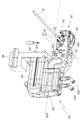
- 도 1은 본 발명에 따른 제직기의 도식적인 사시도이다;
- 도 2는 도 1의 상세부분 II의 확대도로서, 단순함을 위해 하니스(harness)가 생략되어 있다;
- 도 3은, 도 1 및 2의 제직기에 속하는 본 발명에 따른 위사 선택기의 일부 부분들의 두 가지 다른 구성의 확대 사시도이다;
- 도 4는, 위사 선택기 및 제직기가 제1 작업 구성에 있을 때, 도 3에 나타낸 부분들의 일부 및 제직기의 레이피어(rapier)의 일 부분에 대한 위에서 본 사시도이다;
- 도 5는 도 4의 P5 평면을 따른 부분 절단면도(cut view)이다;
- 도 6은, 위사 선택기 및 제직기가 제2 작업 구성에 있을 때의, 도 4와 유사한, 위에서 본 사시도이다;
- 도 7은 도 6의 P7 평면을 따른 부분 단면도이다;
- 도 8은, 위사 선택기 및 제직기가 제3 작업 구성에 있을 때의, 도 7과 유사한 절단면도이다;
- 도 9는, 위사 선택기 및 제직기가 제4 작업 구성에 있을 때의, 도 7과 유사한 절단면도이다;
- 도 10은, 위사 선택기 및 제직기가 제5 작업 구성에 있을 때의, 도 7과 유사한 절단면도이다;
- 도 11은 본 발명의 위사 선택기의 일부 부분들의, 다른 각도를 따른 사시도이다;
- 도 12는 본 발명의 위사 선택기에 속하는 절단 도구(cutting tool) 및 위사 제공기(weft presenter)의 사시도이다;
- 도 13은 도 1의 제직기의 일부 부분들의 높이를 조절하기 위한 구동 어셈블리의 사시도이다;
- 도 14는 도 1의 제직기에 속하는 바디(reed) 및 관련 구동기(associated drive)의 사시도이다.A better understanding of the present invention and other advantages will become more apparent upon reading the following description of an embodiment of the weaving method, the weft selector and the weaving machine according to the present invention, the following description is provided by way of example only, It was prepared with reference to the accompanying drawings as follows:
1 is a schematic perspective view of a weaving machine according to the invention;
FIG. 2 is an enlarged view of detail II of FIG. 1 , with the harness omitted for simplicity;
3 is an enlarged perspective view of two different configurations of some parts of a weft selector according to the invention belonging to the weaving machine of FIGS. 1 and 2 ;
FIG. 4 is a perspective view from above of some of the parts shown in FIG. 3 and a part of a rapier of the weaving machine when the weft selector and the weaving machine are in a first working configuration;
FIG. 5 is a partial cut view along plane P5 of FIG. 4 ;
FIG. 6 is a perspective view from above, similar to FIG. 4 , when the weft selector and the weaving machine are in a second working configuration;
FIG. 7 is a partial cross-sectional view along plane P7 of FIG. 6 ;
FIG. 8 is a cross-sectional view similar to FIG. 7 , when the weft selector and the weaving machine are in a third working configuration;
- Figure 9 is a cross-sectional view similar to Figure 7, when the weft selector and the weaving machine are in the fourth working configuration;
- Figure 10 is a cross-sectional view similar to Figure 7, when the weft selector and the weaving machine are in the fifth working configuration;
- Figure 11 is a perspective view, taken from another angle, of some parts of the weft selector of the invention;
12 is a perspective view of a cutting tool and a weft presenter belonging to the weft selector of the present invention;
FIG. 13 is a perspective view of a drive assembly for adjusting the height of some parts of the weaving machine of FIG. 1 ;
FIG. 14 is a perspective view of a reed and associated drive belonging to the weaving machine of FIG. 1 ;
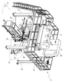
도 1에 도시된 제직기(2)는 갠트리(gantry)(4)를 포함하는데, 갠트리(4)는 지면(G)에 고정된 제직 기계(10) 위에 자카드 기계(Jacquard machine)(6) 및 일부 제어 캐비닛(8)을 지지한다. 갠트리(4)는 또한 지면에 고정된 여러 개의 포스트(12)를 가지며, 이것은 플랫폼(14)을 함께 지지하며, 플랫폼(14)에는 자카드 기계(6) 및 제어 캐비닛(8)이 위치된다.The weaving
종광들(17) 및 도시되지 않은 코드들(cords)로 만들어진 하니스(16)는, 제직기(10)의 레벨에서, 도시되지 않은 크릴(creel)에서 나오는 경사(18)를 사용하여, 도시되지 않은 개구를 형성하도록 수직으로 이동가능하다.A
하니스 코드들 및 종광들(17)의 대안적인 수직 이동은 도 1에서 이중 화살표(A1)로 표시된다.An alternative vertical movement of the harness cords and the heds 17 is indicated by the double arrow A1 in FIG. 1 .
레이피어(20)는 직물(22)을 제직하기 위해 개구 내로 위사(34)를 삽입하기 위해 사용된다. 도 1 및 2에서, 이중 화살표(A2)는, 레이피어 유닛(200)의 레일(201)에 의해 안내될 때, 위사 삽입 축(Y20)을 따라 레이피어(20)의 대안적인 수평 이동을 나타내며, 이때, 레이피어 유닛(200)은 위사 삽입 메커니즘를 형성하고, 또한, 위사 삽입 축(Y20)을 따라 레이피어(20)를 앞뒤로 이동시키기 위한 도시되지 않은 구동기를 포함한다.The
화살표(A3)는 권취 캐리지(take-up carriage)(24)를 향한 제직 직물(22)의 일방향 변위(unidirectional displacement)를 나타낸다.Arrow A3 represents the unidirectional displacement of the woven
바디(reed)(23)는 각각의 위입(pick) 후에 위사들(34)을 직물(22) 내로 바디침(beating)하기 위해 사용된다. 이중 화살표(A23)는 도 2 및 14에서 바디의 바디침 운동(beating movement)을 나타낸다.A
위사(34)는 제직 기계(10) 옆에 위치된 보빈들(26)으로부터 풀리고, 그 자체로 알려져 있고 위사들의 공급에서 흔들림을 방지하도록 설계된 보상기(compensator)(30)를 경유하여 보빈들로부터 공급되어 위사 선택기(28)에 의해 레이피어(20)에 제공된다. 보상기(30)는 이 보상기를 떠나는 위사들(34)의 실질적으로 일정한 장력을 보장한다.The
도면들의 실시예에서, 6개의 보빈들(26)이 지면(G)에 고정된 지지 브래킷(32)위에, 위사 선택기(28) 옆에 그리고 보상기(30) 옆에 장착된다. 위사 선택기(28)에는 최대 12개의 보빈들(26)으로부터 나오는 위사들이 공급될 수 있다. 보빈들(26)의 수는 제직기(2)에서 사용되는 상이한 위사들의 수를 맞추기 위해 증가될 수 있다.In the embodiment of the figures, six
이 실시예에서, 경사들(18)은 폴리에스테르, 폴리아미드 또는 다른 비교적 저렴한 열가소성 재료로 제조된다. 대안적으로, 이들 경사들은 유리, 탄소, 또는 예를 들어, 프로펠러의 블레이드를 위한 3차원 기술의 다층 직물 또는 예를 들어, 자동차의 기술 부품을 위한 2차원의 다층 직물을 생성하기 위한 다른 더 정교한 재료로 만들 수 있다.In this embodiment, the
위사들(34)은 강화 플라스틱, 또는 탄소, 케블라, 세라믹, 아라미드 또는 유리와 같은 섬유로 만들어진다. 전술된 바와 같이, 이들 원사들은 원형, 타원형, 직사각형의 단면, 또는 둥근 모서리가 있는 거의 직사각형의 단면을 가질 수 있다. 원사들은 원형 원사, 테이프, 밴드 또는 리본을 형성할 수 있으며, 너비는 0.014 mm 내지 5 mm 사이이다.The
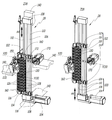
위사 선택기(28)는 수직 축(Z28)을 따라 지면(G)에 대해 변위될 수 있는 수직으로 이동가능한 캐리지(102)를 포함한다. 위사 선택기(28)는 전기 모터(104), 벨트(106), 및 상부 및 하부 방향 변경 박스(108)에 통합된 도시되지 않은 풀리(pulleys)를 포함하는 전기 구동 어셈블리(103)에 의해 변위될 수 있다. 2개의 가이드 레일들(110)은 2개의 박스들(108) 사이에서 수직으로 연장하고, 또한, 구동 어셈블리(103)에 속한다. 구동 어셈블리(103)는 캐비닛들(8) 중 하나에 통합된, 전자 제어 유닛(electronic control unit), 또는 ECU(82)에 의해 조종된다. 이 ECU는 위사 선택기(28)를 조종하기 위한 프로그램을 사용하여, 적어도 하나의 마이크로프로세서 및 메모리를 포함한다.The
수직 이동식 캐리지(102)는 벨트(106)에 의해 상향 또는 하향으로 당겨질 때 가이드 레일들(110)을 따라 활주하도록 적합화된 상부 크로스 빔(upper cross beam 112)(112) 및 하부 크로스 빔(lower cross beam)(114)을 포함한다. 캐리지(102)는 또한, 전진 방향 브래킷(116) 및 후진 방향 브래킷(118)을 포함한다. "전진 방향" 및/또는 "후진 방향"의 개념은, 레이피어(20)가, 위사 삽입 축(Y20)을 따라, 위사 픽업 위치로부터 경사(18)에 의해 형성된 개구 내로 이동할 때, 레이피어(20)의 이동 방향과 관련된다. 레이피어(20)의 전진 방향 이동은 도 1 내지 10에서, 축(Y20)을 따라 오른쪽으로부터 왼쪽으로 진행된다. 이것이 브래킷(116)이 축(Y20)을 따라 브래킷(118)의 전진 방향에 위치되는 이유이다.The vertically
전진 방향 브래킷(116)에는 축(Z28)에 평행한 축(Z116)을 따라 정렬된 전진 방향 아일렛들(eyelets)(126)이 제공된다. 유사하게, 후진 방향 브래킷(118)에는 축(Z28)에 평행한 축(Z118)을 따라 정렬된 후진 방향 아일렛들(128)이 제공된다.
전진 방향 브래킷(116)의 중앙 평면(P116)은 전진 방향 및 후진 방향 표면들 사이에서 한정되며, 이들 두 표면과 동일한 거리에 있다. 후진 방향 브래킷(118)의 중앙 평면(P118)은 전진 방향 평면 및 후진 방향 표면 사이에서 한정되며, 이들 두 표면과 동일한 거리에 있다. 이들 2개의 중앙 평면들(P116 및 P118)은 평행하고 각각 이동식 캐리지(102)를 위한 전진 방향 평면 및 후진 방향 평면을 형성한다. 이들은 축(Y20)에 수직이며 이 축을 따라 오프셋(offset)되어 있다. 전진 방향 및 후진 방향 아일렛들(126 및 128)은 각각 전진 방향 평면(P116) 및 후진 방향 평면(P118)에 위치된다. 즉, 전진 방향 및 후진 방향 아일렛들(126 및 128)은 각각 중앙 평면들(P116 및 P118)과 교차한다.A central plane P116 of the
각각의 전진 방향 아일렛(126)은 축(Y20)에 평행한 종축(Y130)의 방향으로 후진 방향 아일렛(128)과 함께 정렬된다. 전진 방향 아일렛(126) 및 축(Y130)을 따라 이 전진 방향 아일렛과 정렬된 후진 방향 아일렛(128)은, 함께 이 종축(Y130)을 따라 전진 방향 및 후진 방향 브래킷들(116 및 118) 사이에서 연장하는, "분배 채널"이라고 불리는 원통형 용적(130)을 한정한다. 분배 채널의 각각은 축(Y20)에 평행한다. 대안적으로 분배 채널의 각각은 축(Y20)에 평행할 수 있다. 각각의 분배 채널(130)의 종축(Y130)은 이 분배 채널을 한정하는 2개의 아일렛들(126 및 128)의 하부에 접(tangent)한다. 따라서, 분배 채널(130)의 2개의 아일렛들(126 및 128)의 하부에 놓인 위사(34)는 그 종축(Y130)을 따라 연장한다.Each
예를 들어, 분배 채널(130)은 도 4에서 회색 영역으로 식별된다.For example,
이하에서 설명되는 바와 같이, 위사(34)는, 이 분배 채널(130)의 외부의, 픽업 위치에서, 레이피어(20)의 그리퍼(40)에 의해 잡히기 위해, 각각의 분배 채널(130)을 따라 종축(Y130)의 방향으로 활주할 수 있다.As will be described below,
전진 방향 및 후진 방향 아일렛들(126 및 128)은 전진 방향 및 후진 방향 브래킷들(116 및 118)에 만들어진 개구부들에 장착된 링들에 의해 만들어지며, 이들 브래킷들은 축(Y20)에 평행하게 측정하였을 때 두께가 약 5 mm인 반면, 아일렛들은 직경이 약 3 mm이고 가장자리가 둥글다. 따라서, 아일렛들은 2개의 정렬된 아일렛들(126 및 128) 사이에 한정된 분배 채널(130)을 따라 활주하는 위사(34)를 위한 매끄러운 안내 표면들을 제공한다.Forward and
대안적으로, 아일렛들(126 및 128)은 브래킷들(116 및 118)을 통해 직접 천공된 개구부들에 의해 만들어지며, 이들 개구부들은 또한, 위사(34)를 위한 매끄러운 안내 표면을 제공하기 위해 둥근 모서리를 갖는다.Alternatively, eyelets 126 and 128 are made by openings drilled directly through
도면의 실시예에서, 모든 아일렛들(126 및 128)은 동일하다. 이것은 강제적인 것은 아니며, 아일렛의 크기 및 형상은, 분배 채널(130)을 통해 이동하는 위사(34)의 크기 및 단면에 적응하기 위해, 브래킷들(116 또는 118)의 높이를 따라 개조될 수 있다.In the embodiment of the figure, all
이 실시예에서, 전진 방향 또는 후진 방향 브래킷(116 또는 118)의 각각에는 12개의 전진 방향 또는 후진 방향 아일렛들(126 또는 128)이 제공되어, 12개의 분배 채널들(130)이 이 브래킷들 사이에 한정된다; 하나는, 축(Z28)방향으로, 다른 하나 위에 있다. 따라서, 12개의 다른 보빈들(26)으로부터 나오는 12개의 다른 위사들(34)은 위사 선택기(28)에서 취급될 수 있다.In this embodiment, each of the forward or reverse
브래킷 당 아일렛들의 수, 따라서, 분배 채널들(130)의 수는, 제한되지 않으며, 이 수는 적어도 2개이다. 바람직하게는 분배 채널들(130)의 수는 적어도 3개, 더욱 바람직하게는 적어도 5개, 및 더욱더 바람직하게는 적어도 12개이다.The number of eyelets per bracket, and thus the number of
프레임(140)은 위사 선택기(28)의 프레임을 나타내며, 이 프레임은 단순성과 명확성을 위해, 도 3의 왼쪽 및 도 4에만 부분적으로 표시된다. 박스(108) 및 안내 레일(110)은 프레임(140)에 대해 고정되어 있다.
구동 어셈블리(103) 덕분에, 캐리지(102)를 축(Z28)을 따라 프레임(140) 및 지면(G)에 대해, 상향 또는 하향으로, 도 3의 이중 화살표(A4)로 나타낸 바와 같이, 이동하는 것이 가능하다.Thanks to the
이는, 선택된 분배 채널(130)을 위사 삽입 축(Y20)과 정렬시키는 것을 가능하게 하며, 이때, 선택된 분배 채널(130)은 다음 위입(pick) 동안 제직에 사용될 다음 위사에 해당한다. 보다 정확하게는, 선택된 분배 채널(130)의 종축(Y130)은 캐리지(102)의 수직 이동에 의해 축(Y20)과 정렬될 수 있다. 캐리지(102)의 이러한 수직 상향 또는 하향 이동은 프레임(140)에 대해 이루어지며, 도 3에 나타낸 위사 선택기(28)의 두 구성의 비교에 의해 이해될 수 있다. 이 설명에서, 분배 채널(130)은, 분배 채널(130)의 종축(Y130)이 위사 삽입 축(Y20)과 정렬될 때, 이 위사 삽입 축(Y20)과 정렬된다고 한다. 도 3의 왼쪽 구성에서, 캐리지(102)의 상부 분배 채널(130)은 축(Y20)과 정렬되는 반면, 오른쪽 구성에서, 캐리지(102)의 상부에서 시작하는 제5 분배 채널(130)은 축(Y20)과 정렬된다.This makes it possible to align the selected dispensing
캐리지(102)의 이동 스트로크는 구동 어셈블리(103)에 의해 한정된다. 이 스트로크는 도 3의 왼쪽에 표시된 위치와 최하단 분배 채널(130)이 위사 삽입 축(Y20)과 정렬되는 위치 사이의 캐리지(102)의 이동에 해당한다. 이 스트로크는 12개의 분배 채널(130)들을 포함하는, 도면의 실시예의 캐리지(102)에 대해 약 140 mm이다.The travel stroke of the
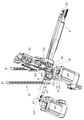
바스켓(150)은 다중 위사 선택기(28)의 프레임(140)에 의해 지지되고, 그리퍼(40)를 운반하는 레이피어(20)의 헤드(202)를 수용하도록 구성된다.
그리퍼(40)는 2개의 턱들(jaws)(42)을 갖는다.The
바스켓(150)은 레이피어 헤드(202)를 위사 선택기(28)에 대해 경사 방향(warp-wise)으로 그리고 수직으로 위치시키기 위한 2개의 안내 표면들을 갖는다. 보다 정확하게는, 바스켓은 축(Y20)에 평행한 수평 하부 표면(152) 및 위사 선택기(28)의 방향으로 축(Y20)을 향해 경사진 상부 경사 표면(154)을 포함한다. 바스켓(150)은 레이피어 헤드(202)를 축(Y20)을 따라, 도 5의 화살표(A5) 방향으로, 즉 전진 방향 브래킷(116)에 가까운 위사를 픽업하기 위한 픽업 위치를 향하도록 안내하는데 적합하다. 이것은, 도 5에 도시된 바와 같이, 축(Y20)과 정렬된 분배 채널의 전진 방향 아일렛(126)에 대해 그리퍼(20)를 정확하게 위치시키는 것을 허용한다.The
본 발명의 도시되지 않은 대안적인 구현예에 따르면, 그리고 레이피어(20)가 도 4 및 5에 표시된 픽업 위치에 도달할 만큼 충분히 강성(stiff)이면, 바스켓(150)은 생략될 수 있다. 대안적으로, 바스켓은, 레이피어를 위치시키기 위한 안내 수단들, 예를 들어, 슬롯(slot), 램프(ramp), 모션 링크(motion link) 또는 크랭크(crank)가 장착된 임의의 다른 대안 해결책에 의해 대체될 수 있다.According to an alternative, not shown, embodiment of the present invention, and provided that the
분배 채널(130)의 각각은 축(Y130)을 따라 활주 가능하게 이동가능하고 이 축에 평행한 2개의 레일들(132 및 134)에 의해 안내되는 위사 제공기(160)를 구비한다. 위사 제공기(160)는 대응하는 분배 채널(130)의 용적 내에 완전히 둘러싸여 있지 않지만, 부분적으로는 이 채널에, 그리고 부분적으로는 이 채널 외부에, 브래킷들(116 및 118) 사이에 위치된다. 명확성을 위해, 2개의 레일들은 도 5 및 도 7 내지 도 10에만 표시되어 있다. 도 11에서는 이들은 이들의 각각의 축들(Y132 및 Y134)에 의해 표시된다. 2개의 하우징(1626 및 1628)은, 작은 방사상 유격으로 레일들(132 및 134)의 일부를 수용하기 위해, 각각의 위사 제공기(160)의 본체(162) 내에 제공되어, 본체(162)가 2개의 레일들(132, 134)을 따라 활주하도록 한다.Each of the
단순함을 위해, 단지 하나의 위사 제공기(160)가 도 4 및 6에 표시되었다. 그러나, 12개의 위사 제공기들(160)은 도 3에서 볼 수 있는 바와 같이 캐리지(102)에 장착될 수 있다.For simplicity, only one
각각의 위사 제공기(160)는 전진 방향 및 후진 방향 브래킷들(116 및 118) 사이에서 분배 채널(130)을 따라 이동가능하다. 보다 정확하게는, 각각의 위사 제공기(160)는, 위사 제공기(160)가 후진 방향 브래킷(118)에 근접하는 도 4 및 5에 표시된 후진방향 또는 후퇴 위치와, 위사 제공기(160)가 전진 방향 브래킷(116)에 근접하는 도 6 내지 10에 도시된 전진 방향 위치 사이에서 레일들(132 및 134)을 따라 활주할 수 있다. 위사 제시기(160)의 전진 방향 위치는, 또한 이 위치에서 위사 제시기(160)가 위사(34)를 그리퍼(40)에 공급할 수 있기 때문에 공급 위치이다.Each
각각의 위사 제공기(160)의 변위는, 위사 제공기(160)가 체결되는 분배 채널(130)을 따라, 전진 방향 및 후진 방향 브래킷들(116 및 118) 사이에서, 이 분배 채널(130)의 종축(Y130)을 따라 그리고 위사 삽입 축(Y20)을 따라 발생한다. 이 변위는, 크랭크 메카니즘(174)을 통해, 축들(Y20, Y130, Y132 및 Y134)에 평행한 축(Y172)을 따라 병진 방향으로(in translation) 로드(rod)(172)를 구동하는 전기 모터(170)에 의해 얻어진다. 전기 모터(170)는 프레임(140)에 고정적으로 장착되고 ECU(82)에 의해 조종된다. 전기 모터(170), 로드(172) 및 크랭크 메커니즘(174)은 함께, 선택된 위사 제공기(160)를, 폰트 브래킷(font bracket)(116)을 향해 이동시키기 위한 전기 구동 어셈블리(173)를 형성한다.The displacement of each
스프링(176)은 위사 제공기(160)와 전진 방향 브래킷(116) 사이에 개재된다.A
도 5의 위치로부터 도 7의 위치로의 위사 제공기(160)의 전진 방향 이동은, 크랭크 메카니즘(174)에 의해 작동되는 로드(172)에 의해 가해지는 힘(F6)의 작용하에, 도 5의 화살표(A6)의 방향으로 발생하며, 이 힘은 축(Y172)을 따라 정렬된다. 이 힘(F6)은 위사 제공기(160)의 본체(162)의 후면(1622)에 가해지는 미는 힘(pushing force)이다. 위사 제공기(160)를 화살표(A6)의 방향으로 이동시키기 위해, 본체(162)에 놓인 전기 모터(172), 크랭크기구(174) 및 로드(172)를 포함하는 전기 구동 어셈블리(173)를 사용하는 것은, 공압 구동기(pneumatic drive)로 얻을 수 있는 것보다, 더 원활한 위사 제공기(160)의 전진 방향 이동을 제공한다. 따라서, 보빈(26)으로부터 위사(34)를 풀어내기 위해 연관된 위사 제공기(160)에 의해 위사(34)에 가해지는 잡아당기는 작업이 더 원활하게 된다.The forward movement of the
도 7의 위치로부터 도 5의 위치로의 위사 제공기(160)의 후진 방향 이동은, 후진 방향 브래킷(118)을 향해 그리고 본체(162)의 전면(1624)에서 스프링(176)에 의해 가해지는 탄성력(F6')의 작용 하에서, 도 5의 화살표(A6')의 방향으로 발생한다. 따라서, 스프링(176)은 위사 제공기(160)를 도 4 및 5에 도시된 후퇴 위치를 향해 다시 밀어 내도록 구성된 탄성 복귀 수단들을 구성한다.The backward movement of the
위사 제공기(160)는 또한, 고정식 클램프 턱(1642) 및 이동식 클램프 턱(1644)으로 형성된 클램프(164)를 포함한다. 고정식 턱(1642)은 본체(162)에 대해 고정되어 있다. 이동식 턱(1644)은 축들(Y132 및 Y134)에 수직인 비-가시적인 축 주위로 본체에 접합된다.The
각각의 클램프(164)는 위사 제공기(160)에 속하기 때문에, 분배 채널(130)의 종축(Y130)을 따라 그리고 이 위사 제공기의 본체(162)와 함께, 도 4와 5에 도시된 후진 방향 또는 후퇴 위치와 도 6에서 10에 도시된 전진 방향 또는 공급 위치 사이에서, 이동가능하다.Since each
스프링(166)은 각각의 위사 제공기(160)의 본체(162)에 장착되며, 클램프(164)가 위사 제공기(160)에 대해 고정된 위사(34)의 일부를 유지하는 위치에서, 기본적으로(by default) 이동식 턱(1644)을 고정식 턱(1642)을 향해 밀어 낸다. 즉, 기본적으로, 위사(34)는 도 11의 화살표(A11)로 나타낸 바와 같이 클램프(164)에 의해 클램핑된다.A
고정식 턱(1642)는 이동식 턱(1644)의 코 부분(nose part)(1643)을 수용하도록 구성된 U자 형상의 홈을 갖는다. 2개의 턱들(1642 및 1644), 특히 코 부분(1643)의 기하학적 구조는, 클램프(164)에 의해 클램핑된 위사(34)의 손상 위험을 제한하기 위해 선택된다. 고정식 턱(1642)의 U자 형상은 특히 상이한 종류의 위사 재료를 안내하고 본체(164)에 대해 위사(34)를 고정하도록 적합화됨으로써, 느슨한 실 또는 흔들리는 실의 경우, 위사가 클램프(164)로부터 미끄러지는 것을 방지한다.The
도면의 실시예에서, 모든 위사 제공기(160)의 모든 클램프들(164) 및 모든 스프링들(166 및 176)은 동일하다. 그러나, 도시되지 않은 대안적인 구현예에서, 클램프(164) 및 스프링들(166 및 176)은, 대응하는 분배 채널(130)을 통과하는 위사(34)의 형상 및 유형 재료를 완벽하게 맞추기 위해 각각의 위사 제공기(160)에 대해 맞춤화될 수 있다.In the embodiment of the figure, all clamps 164 and all
대응하는 스프링(166)에 의해 가해지는 탄성력에 대항하여, 각각의 클램프들(164)의 개방 운동을 제어하기 위해 전기 모터(180)가 제공된다. 이 전기 모터(180)는 프레임(140)에 견고하게 장착되고, ECU(82)에 의해 조종된다. 이것은 바스켓(150) 옆에 배치되며, 위사 제공기가 전진 방향 위치로 이동되었을 때, 위사 삽입 축(Y120)과 정렬된 단일 분배 채널(130)의 위사 제공기(160)의 클램프(164)와 상호작용할 수 있도록 위치된다. 즉, ECU(82)에 의해 적합하게 조종되는 단일 전기 모터(180)는, 이러한 위사 제공기(160)가 레이피어(20), 특히 그리퍼(40)와 정렬된 분배 채널(130)에 위치할 때, 그리고 위사 제공기가 공급 위치에 있을 때, 임의의 위사 제공기(160)의 클램프(164)를 선택적으로(selectively) 작동시키기 위해 사용된다. An
전기 모터(180)는 편심기(eccentric)(184)를 통해 롤러(182)를 구동한다. 부품들(180, 182 및 184)은 함께 전진 방향 또는 공급 위치에서 위사 제공기의 클램프(164)를 조작하기 위한 전기 구동기(183)를 형성한다. 롤러(182)는, 약 3 mm의 거리에서, 고정식 턱(1642)에 대해 이동식 턱(1644)을 선택적으로(selectively) 들어올리도록 설계된다.The
전기 구동기(183)가 클램프(164)에 작용하지 않을 때, 이 클램프(164)는, 스프링(166)에 의해 가해지는 탄성력 하에서, 수평면에 대해 폐쇄되어, 클램프된 위사(34)는 대응하는 분배 채널(130)에서 실질적으로 직선 상태를 유지한다. 즉, 위사를 클램핑하기 위해 분배 채널(130)을 통과하는 이 위사(34)를 구부릴 필요가 없다.When the
프레임(140)에 대한 전기 모터(180)의 위치 때문에, 롤러(182)는, 도 6 내지 10에 도시된 전진 방향 또는 공급 위치에 도달하기 위해, 위사 제공기가 전기 모터(170)에 의해 전진 방향으로 밀렸을 때만, 위사 제공기(160)의 클램프(164)와 상호작용한다. 즉, 위사 제공기(160)의 클램프(164)는, 위사 제공기가 축(Y20)에 정렬된 분배 채널(130)에 위치하는 경우 및 이 위사 제공기(160)가 전기 구동 어셈블리(173)에 의해 공급 위치로 전진 방향으로 이전에(previously) 밀려 난 경우에만, 전기 모터(180)에 의해서 개방될 수 있다.Because of the position of the
도 5에서만 볼 수 있고 화살표(A190)로 표시된 관측 방향을 갖는, 수직 배향된 광학 센서(190)는, 위사 선택기(28)의 하부, 이동식 캐리어(102)의 아래에 설치되고, 프레임(140)에 의해 지지된다. 이 센서(190)는 적어도 하나의 위사 제공기가 전진 방향 또는 공급 위치에 있는지 또는 모든 위사 제공기들(160)이 후진 방향 또는 후퇴 위치에 있는지를 결정할 수 있게 한다. 이 센서(190)는 또한, 이 클램프가 전진 방향 또는 공급 위치에 있는 위사 제공기에 속할 때, 클램프(164)의 개방 상태를 확인할 수 있다. 대안적으로, 클램프(164)의 상태를 확인하는 것은 다른 도시되지 않은 센서로 이루어질 수 있다.A vertically oriented
센서(190)의 출력 신호는 전기 구동기(103, 173 및 183)를 작동시키기 위해 ECU(82)에 의해 고려된다. 특히, 클램프 중 하나가 전진 방향 위치에 있으면 전기 구동기(103)가 작동될 수 없고, 개방된 경우에는 더욱더 그렇다.The output signal of the
절단 도구(210)는 바스켓(150) 옆에 설치되며 상부 블레이드(212) 및 하부 블레이드(214)를 포함한다. 상부 블레이드는 절단 유닛(220)의 몸체(222)에 대해 고정되어 있으며, 절단 유닛(220)을 축(Y20)에 수직인 수평축(X220)을 따라 이동시키기 위한, 제1 선형 공압 구동기(224), 및 위사(34) 절단이 필요할 때, 상부 블레이드(212)에 대해 하부 블레이드(214)를 이동시키기 위한 제2 공압 구동기(226)를 포함한다. 유체 커넥터들(2262 및 2264)은 공압 구동기(226)를 도시되지 않은 공기 튜브들에 연결한다.The
이 실시예에서, 단일 절단 유닛(220), 따라서, 단일 절단 도구(210)는 위사 삽입 축(Y20)에 정렬된 이동식 캐리지의 임의의 분배 채널(130)을 통과하는 위사들(34)을 선택적으로(selectively) 절단하기 위해 사용된다.In this embodiment, a
공압 구동기(224 및 226)에 공기를 제공하기 위해 도시되지 않은 압력하의 공기 공급원도 또한, ECU(82)에 의해 제어된다. An air supply under pressure, not shown, to provide air to the
도 12에만 표시되고 관찰 방향이 화살표(A230)의 방향으로 연장하는 광학 센서(230)는, 특히 블레이드들의 교차가 발생할 때, 즉, 위사(34)가 절단될 때, 서로에 대한 블레이드들(212 및 214)의 위치를 감지할 수 있도록 한다. 그것의 출력 신호도 또한, ECU(82)에 제공된다.The
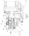
3차원 제직 영역에서, 특히 이중 레이피어 시스템이 사용될 때. 중첩된(superposed) 위사를 삽입하는 것이 문제이다. 이러한 용도에서는 최종 직물이 상대적으로 두껍기 때문에, 자카드 시스템(Jacquard system)은, 지면(G)에 대해 높이가 다른 제직 기계(10)의 프레임에 대해 상이한 높이에 있는 상이한 연속 개구들을 개방한다. 한편, 제직 공정을 최적화하기 위해서는, 개구 높이를 비교적 작게 유지하는 것이 더 좋다.In the realm of three-dimensional weaving, especially when dual rapier systems are used. Inserting superposed weft is a problem. Because the final fabric is relatively thick in this application, the Jacquard system opens different successive openings at different heights relative to the frame of the weaving
상이한 높이에 위치된 상이한 개구들에 위사 삽입을 용이하게 하기 위해, 본 발명의 제직기(2)는 승강 시스템(elevation system)(300)을 포함하며, 승강 시스템(300)은 레이피어 유닛(200)을 수직으로 이동시키기 위한 제1 상승 장치(310) 및 위사 선택기(28)를 수직으로 상승하기 위한 제2 상승 장치(320)를 포함한다.To facilitate weft insertion in different openings located at different heights, the loom 2 of the present invention comprises an
승강 시스템(300)만이 개략적으로 도시된 도 13에서, 가이드 레일(201)은 레이피어 유닛(200)을 나타내고 프레임(140)은 위사 선택기(28)를 나타낸다.13 , in which only the
제1 상승 유닛(310)은 지면(G)에 고정된 고정 프레임(312) 및 레이피어 유닛을 지지하기 위한 이동식 프레임(314)을 포함한다. 서보 구동기(servo-drive)(316)는 3개의 각진 기어 박스들(318)을 통해 3개의 웜 기어들(worm gears)을 구동한다. 이것은 3개의 볼 스크류 스핀들(319)을 수직으로 그리고 동시에 이동시킬 수 있게 한다. 따라서, 이동식 프레임(314)을 지면(G)에 평행하게 유지하면서 이동식 프레임(314)의 수직 상승이 제어될 수 있다.The
한편, 제2 상승 장치(320)는 지면(G)에 고정된 고정식 프레임(322) 및 위사 선택기(28)의 프레임(140)을 지지하는 이동식 프레임(324)을 포함한다. 서보 구동기(326)는 이동식 프레임(324)을 수직으로 이동시키기 위해 기어 박스(328) 및 볼-스크류 스핀들(329)을 구동한다.Meanwhile, the
두 개의 상승 장치(310, 320), 특히 이들의 각각의 서보 구동기(316 및 326)는, 방향, 속도 및 가속도의 관점에서, 언제든지 2개의 이동식 프레임(314 및 324)의 동일한 변위를 얻기 위해, ECU(82)에 의해 전자 제어된다. 하나의 서보 구동기는 마스터(master)가 될 수 있고 다른 하나는 슬레이브(slave)가 될 수 있다.The two
또한, 위사들이 중첩된 개구들 내에 연속적으로 삽입될 때, 이중 화살표(A200)으로 표시된 바와 같은 위사 삽입 메커니즘(200) 및 이중 화살표(A28)로 표시된 바와 같은 위사 선택기(28)를 수직으로 함께 이동시킴으로써, 위사 선택기(28)가 위사 삽입 메커니즘(200)와 항상 수평으로 정렬되도록 유지하는 것을 허용한다. 시스템(300) 덕분에, 위사 삽입 메커니즘(200) 및 위사 선택기(28)의 수직 위치, 따라서, 위사 삽입 축(Y20) 및 선택된 분배 채널(130)의 수직 위치를 지면(G) 및 제직 기계(10), 특히 제직된 직물(woven fabric)(22)에 대해 조정할 수 있다. 위사 삽입 메커니즘(200) 및 위사 선택기의 상승은, 이동식 캐리지(102)의 위치를 조정하는 것과, 시간 상으로 중첩되어, 가동 중지 시간을 감소시킬 수 있다.Also, when the weft yarns are successively inserted into the overlapping openings, the
대안적으로, 2개의 상승 장치들은 공통 축(common shaft)을 통해 기계적으로 결합될 수 있다. 이러한 경우, 예를 들어, 서보 구동기(316)과 같은 단일 구동기를 사용할 수 있다. 공통 축은 여기 아래에서 고려되고 도 14에 도시된 바디의 서보 구동기 축와 동축일 수 있다.Alternatively, the two lifting devices may be mechanically coupled via a common shaft. In this case, for example, a single driver such as
기계적인 캠(cam) 연결을 통해 제직 기계의 주축에 접합된 슬리(sley)라고도 불리는 바디를 사용하는 것이 종래 기술로부터 알려져 있다. 바디는 그 위치를 안정시키기 위해 각각의 위사를 직물로 바디침(beating-up)한다. 바디의 운동은 캠 프로파일(cam profile)에 따라 달라지며, 기계적인 캠 연결을 변경하지 않고는 적합화할 수 없으며, 이는 복잡하다. 바디의 운동은 기본적으로 원형 운동이며, 이는 일부 위사 재료, 특히 탄소 구조를 포함하는 위사 재료에 대해 바람직하지 않다.It is known from the prior art to use a body, also called a sley, bonded to the main shaft of a weaving machine via a mechanical cam connection. The body beats-up each weft with the fabric to stabilize its position. The motion of the body depends on the cam profile and cannot be adapted without changing the mechanical cam connection, which is complex. The motion of the body is essentially a circular motion, which is undesirable for some weft materials, especially weft materials comprising a carbon structure.
본 발명의 제직기(2)에서, 양방향 화살표(A23)로 표시된 바디(reed)(23)의 대안적인 운동(movement)은 독립적인 구동 메커니즘(400)에 의해 얻어지며, 구동 메커니즘(400)은, 전기 모터(412), 일 세트의 연결 로드들(414), 크랭크 메커니즘(416), 및 2개의 브래킷(brackets)(422)을 통해 주축(main shaft)(420)에 관절식으로 연결(articulated)되는 서브프레임(sub-frame)(418)을 포함한다. 플라이휠(444)도 구동 메커니즘(400)에 속한다.In the weaving
이 구동 메커니즘(400)은, 전기 모터(412)의 연속적인 회전 운동을, 도 2 및 14에서 화살표(A23)로 표시된 대안적인 수평 운동으로 변환하는 것을 가능하게 한다. 바디의 일측 만이 구동 메커니즘(400)에 연결되어 있기 때문에, 구동 메커니즘(400)의 구조는 바디(23)의 일 구역(section)이 돌출(overhang)되도록 한다.This
구동 메커니즘(400)를 통해 획득된 운동의 변환 덕분에, 바디(23)의 운동은 주로 수평적이며, 이는 상당한 두께를 갖는 다층 직물(22)을 제직하고 바디침(beating-up)하는 데 유리하다. 이렇게 얻어진 결과는, 가장 많이 바디침된 부분이 직물의 가장 높은 층인 회전식 바디를 사용한 경우보다 더 우수하다. Thanks to the transformation of the motion obtained via the
모터(412)는 전기 모터이기 때문에, 그것의 작업 조건은 ECU(82)에 의해 조종(piloted)될 수 있고 쉽게 맞춤화(customized)될 수 있다. 이 전기 모터(412)의 회전 방향은 빠르게 반전될 수 있다. 바디 운동의 스트로크(stroke), 속도, 및 가속도를 조정할 수 있으므로, 바디 운동의 지속시간 및 가속도를 쉽게 변경할 수 있다. 바디(23)가 서보 구동되기 때문에, 그것의 운동은 자카드 기계(6)의 운동 법칙으로부터 그리고 절단 및 위사 삽입 공정으로부터 독립적이다. 바디(23)의 운동의 가속도, 속도, 위치, 및 진폭은, 제직 공정, 실의 재료, 및 제직된 직물(22)의 실제 구조에 쉽게 적합화될 수 있다.Since the
또한, 바디(23)에 의해 직물에 가해지는 힘은 측정되거나, 또는, 특히 모터(412)에 의해 생성된 토크에 기초하여, 계산에 의해 산정될 수 있다. 이는, 제직될 직물, 실의 재료, 제직 공정의 속도 등에 따라, 바디의 스트로크를 적합화(adapting)하는 것을 가능하게 한다. 특히, 제직기(2)의 ECU(82)에 의한 토크 측정 및 그 해석은 실의 장력에 대한 정보를 제공하고, 이는 도시되지 않은 수단에 의해 모니터링 및 조정될 수 있다.Furthermore, the force exerted on the fabric by the
이하에서는, 도 1 내지 도 14에 나타낸 제직기로 구현된 제직 방법이 설명된다.Hereinafter, a weaving method implemented with the weaving machine shown in FIGS. 1 to 14 is described.
필요한 경우, 시스템(300)은, 지면(ground)(G)을 기준으로 한 개구(shed)의 실제 높이 및 위사들의 위치에 적합화되기 위해, 위사 삽입 메커니즘(200) 및 위사 선택기(28)를 상승시키는 데 사용될 수 있다. 이는, 새로운 직물의 제직을 시작할 때 또는 제직 동안에, 특히 두 번의 위사 삽입 사이클들 사이에서, 수행될 수 있다.If necessary, the
레이피어 헤드(rapier head)(202)가 픽업 위치로 돌아갈 때마다, 그것의 그리퍼는, 알려져 있는 도시되지 않은 메커니즘에 의해 개방되며, 그에 따라, 위사 단부(weft extremity)의 폐쇄가능한 수용 부피(closable volume of reception)가 형성된다. 대안적으로, 레이피어 헤드(202)는 위사 축을 따라 픽업 위치에 도달하기 전에 개방될 수 있다.Each time the
센서(190)는, 어떠한 위사 제공기(160) 및 어떠한 클램프(164)도 그것의 전진 또는 공급 위치에 있지 않다는 것을 확인하기 위해 각각의 분배 채널들(130) 내의 모든 위사 제공기들(160)의 위치를 모니터링하는데 사용된다. 이는, 이동식 캐리지(102)의 수직 변위 동안 위사(34) 및 이동식 캐리지(102) 사이의 충돌을 방지하는 것을 가능하게 한다. The
"선택된 실(selected yarn)"이라고 불리는 다음 위입(pick)에서의 위사 삽입에 사용될 다음 위사에 따라, 분배 채널들(130) 중 하나가 ECU(82)에 의해 선택된다. 선택된 분배 채널은 선택된 실이 위치되는 분배 채널이다.One of the
그 다음, 구동 어셈블리(103)는, 선택된 분배 채널(103)을 위사 삽입 축(Y20)에 정렬하기 위해 이동식 캐리지(102)를 수직으로 이동 또는 유지하도록, ECU(82)에 의해 조종된다. 즉, 선택된 위사(34)는 그리퍼와 정렬된다. 이는, 개구 개방 동안에 발생할 수 있다. 선택된 실이 이전 위입에서 사용된 실과 다르다면, 이는 이동식 캐리지(102)의 수직 운동을 의미한다. 선택된 위사가 이전 위입에서 사용된 것과 동일한 경우에는, 이동식 캐리지(102)는 이동되지 않은 것이고, 이전에 선택된 분배 채널(130)은 위사 삽입 축과 정렬된 상태로 유지된다. 레이피어 헤드는, 위사 선택기(28)의 이동식 캐리지(102)를 위치시키기 전에, 개방된다. 대안적으로, 레이피어 헤드 개방은 이동식 캐리지(102)의 위치 설정과 시간적으로 중첩될 수 있으며, 그에 따라, 그리퍼(40)는 선택된 위사(34)와 정렬된다.The
그 다음, 전동 모터(170)가 작동되어, 미는 힘(F6)을 가하는 로드(172)를 통해, 선택된 분배 채널(130)에 위치된 위사 제공기(160)를 전진 방향으로(즉, 전진 방향 브래킷(forward bracket)(116) 쪽으로) 밀게 된다. 클램프(164)는, 기본적으로(by default), 도 11의 화살표(A11)로 나타낸 바와 같이, 스프링(166)에 의해 폐쇄되기 때문에, 화살표(A6)으로 표시된 위사 제공기(160)의 이러한 전진 방향 이동은, 위사(34)의 유사한 전진 방향 이동을 유도하며, 이때, 위사(34)는 클램프(164)에 의해 클램핑되고, 대응하는 보빈(26)으로부터 잡아당겨진다. 여기서, 선택된 분배 채널(130) 내의 위사 제공기(160)의 클램프(164)는, ECU(82)에 의해 조종되는 전기 구동 어셈블리(173)에 의해, 그것의 후퇴 위치로부터 그것의 전진 방향 위치로 이동된다. 클램프(164) 및 클램프(164) 내의 클램핑된 위사(34)의 이러한 전진 이동 동안, 그리퍼(40)는 도 7에 도시된 바와 같이 개방된 상태로 유지된다.Then, the
이는, 스프링(176)에 의해 가해지는 탄성력(F6')에 대항하여, 위사 제공기(160) 및 클램프(164)가 도 6 및 7의 전진 방향 위치에 도달하는 것을 가능하게 한다. 이 위치에서, 도 7에 도시된 바와 같이, 위사(34)는 클램프(164)에 의해 클램핑되고, 그것의 자유 단부(342)는, 축(Y20)에 평행하게 측정된 거리(d) 상에서, 캐리지(102)로부터 돌출한다. 거리(d)는, 자유 단부(342)가 그리퍼(40)의 턱들(jaws)(42) 사이에서 연장하기에 충분히 크다.This enables the
따라서, 도 6 및 7의 전진 방향 위치에서, 클램프(164)는, 그리퍼(40)의 공급을 허용하는 위치에서, 위사(34)를 유지한다.Accordingly, in the forward direction position of FIGS. 6 and 7 , the
그 다음, 도 8의 화살표(A8)로 나타낸 바와 같이, 미도시된 작동 수단에 의해 그리퍼(40)의 턱들(42)을 서로를 향해 이동시킴으로써, 그리퍼(40)를 닫는 것이 가능하다. Then, as indicated by arrow A8 in FIG. 8 , by moving the
그 다음, 도 9의 화살표(A9)로 나타낸 바와 같이, 전기 구동 어셈블리(183)의 작용에 의해, 앞에서 설명한 대로, 클램프(164)가 개방된다. 이는 선택된 위사(34)의 클램핑을 해제하고, 위사를 위사 제공기(160)로부터 분리한다.Then, as indicated by arrow A9 in FIG. 9 , by the action of the
그 다음, 도 10에 도시된 바와 같이, 레이피어(20)는 바스켓(150)을 떠나고, 위사(34)를 개구 내로, 화살표(A10)으로 표시된 전진 방향으로, 당긴다. 개구를 통한 레이피어의 이러한 이동 동안, 위사(34)는 그것의 보빈으로부터 풀린다. 필요한 경우, 위사를 장력 상태로 유지하기 위해, 클램프(164)에 의해 제동 노력(braking effort)이 가해질 수 있다. 이를 위해, 전기 구동 어셈블리(183)는, 제어된 제동 노력을 발휘하기 위해, 스프링(166)에 의해 가해지는 탄성력하에 이동식 턱(1644)을 고정식 턱(1642)을 향해 이동시키도록, ECU(82)에 의해 작동될 수 있다.Then, as shown in FIG. 10 , the
위사가 절단되는 위치는, 위사 삽입 축(Y20)을 따른 절단 도구(210)의 위치에 의해 설정된다. 여기서, 직물(22)에 다양한 길이의 위사들을 제직하기 위해, EP-A-3121317의 가르침을 사용할 수 있다. 그러나, 이는 강제적인 것은 아니다. 이러한 경우, 위사(34)는 미리 설정된 길이로 절단되고, 그 후, 절단된 위사(34)는, 전진 방향(A10)으로, 미리 설정된 위치에서 개구 내로 인입된다.The position at which the weft is cut is set by the position of the
레이피어 헤드(202)가 개구 내로의 설정 위치에 도달하면, 스프링(166)의 작용하에 클램프(164)가 닫히도록 하기 위해, ECU(82)에 의해 전기 모터(180)가 다시 작동된다. 그 다음, 위사를, 절단하기 위해 그리고 절단 후에도 손실되지 않도록 하기 위해, 다시 클램핑한다. When the
도 10에 도시된 단계 후에 그리고 위사를 클램핑한 후에, 제1 공압 구동기(pneumatic drive)(224)가 작동되어, 절단 유닛(220)을, 축(X220)을 따라, 바스켓(150)을 통해 연장하는 실(34)을 향해, 이동시킨다.After the step shown in FIG. 10 and after clamping the weft, a first
그 다음, 하부 블레이드(214)를 이동시켜 위사(34)를 절단하기 위해, 제2 공압 구동기(226)가 작동된다. 센서(230)를 사용하여, 다음 단계로 이동하기 전에 위사 절단이 완료되는 것을 제어할 수 있다. 그 다음 절단 도구는 구동기(226)에 의해 다시 개방되고, 구동기(224)에 의해 그것의 원래 위치로 다시 이동된다.The second
그 다음, 전기 구동 어셈블리(173)가 작동되어 로드(172)를 후진 방향 이동시키며, 이는, 스프링(176)이, 탄성력(F6')을 통해, 위사 제공기(160)를 후진 방향으로, 그것의 후퇴 위치 내로, 후진 방향 브래킷(118)을 향해, 화살표(A6') 방향으로, 미는 것을 가능하게 한다. 이러한 후진 방향 이동 동안, 클램프(164)가 모터(180)의 이전 작동에 의해 닫혔기 때문에, 클램프(164)는 위사(34)를 클램핑하고, 전진 방향 아일렛(forward eyelet)(126)은 위사(34)를 안내한다.Then, the
대안적으로, 클램프(164)는, 그것의 전진 방향 위치 및 롤러(182)와의 접촉 위치를 떠나는 것에 의해 닫힐 수 있다. 대안적으로, 클램프는 위사를 절단하기 직전에 후진 방향 이동을 시작할 수 있으며, 그에 따라, 그리퍼와 클램프 사이에서 위사 유지의 필요한 장력이 생성되도록 하여, 효율적인 절단 작업이 수행되도록 할 수 있다. 절단 후, 클램프는 그것의 후퇴 위치로의 그것의 후진 방향 이동을 종료한다.Alternatively, clamp 164 may be closed by leaving its forward position and contact position with
이는, 위사 제공기(160), 클램프(164) 및 위사(34)를 도 4 및 5의 위치로 되돌리고, 거기에서, 위사 단부(342)는, 이동식 캐리지(102)로부터, 전진 방향 아일렛(126)을 통해, 거리(d)보다 작은 거리(d')만큼, 여전히 돌출하며, 클램프(164)는 위사(34)를 여전히 클램핑한다.This returns the
실제로, 도 6 내지 10의 위치와 도 4 및 5의 위치 사이의 위사 제공기(160)의 후진 방향 이동의 스트로크(S)는 거리(d)와 거리(d') 사이의 차이와 동일하다. 다음 방정식이 적용된다:In practice, the stroke S of the backward movement of the
S = d - d' (방정식 1)S = d - d' (Equation 1)
스트로크(S)는 거리(d')가 0보다 엄밀하게(strictly) 크게 유지되도록 선택된다. 다음 방정식이 적용된다:The stroke S is chosen such that the distance d' remains strictly greater than zero. The following equation applies:
S < d (방정식 2)S < d (Equation 2)
d' > 0 (방정식 3)d' > 0 (Equation 3)
즉, 선택된 분배 채널(130)에서의 위사 제공기(160) 및 클램프(164)의 후진 방향 이동의 종료시에, 위사 단부(342)는, 영이 아닌 거리(d')에 걸쳐, 위사 삽입 메커니즘(200)의 방향으로, 전진 방향 아일렛(126)으로부터 돌출한다. 따라서, 위사(34)는 대응하는 분배 채널(130)의 전진 방향 아일렛(126)에 의해 안내되고, 클램프(164)의 후진 방향 이동 동안 클램프(164)에 의해 클램핑된다. 위사는 이러한 후진 방향 이동의 종료시에 전진 방향 아일렛(126)으로부터 체결해제(disengaged)되지 않는다. 따라서, 다음에 이 분배 채널의 위사(34)가 다음 위입을 위해 사용될 때, 클램프(164)가 그것의 공급 위치를 향한 그것의 이동을 시작할 때, 자유 단부(342)가 이동식 캐리지(102)로부터 이미 돌출할 것이며, 이는 그리퍼가 닫힐 때 그리퍼가 위사를 확실히 붙잡게 되는 것과 같은 방식이다. That is, at the end of the backward movement of the
스트로크(S)의 값은 12 mm 이하, 바람직하게는 10 mm 이하, 더욱 바람직하게는 5 mm 이하로 선택된다.The value of the stroke S is chosen to be 12 mm or less, preferably 10 mm or less, more preferably 5 mm or less.
거리(d')는 또한, 레이피어 헤드(202)가 바스켓(150) 내에 있을 때, 그리퍼(40)와 전진 방향 브래킷(116) 사이에서, 축 Y20을 따라 측정된 거리(d40)보다 더 작게 선택된다. 따라서, 레이피어 헤드(202)가 이미 그것의 픽업 위치에 있더라도, 캐리지(102)가 축(Z28)을 따라 이동할 때 각각의 위사 단부들(342)을 아밍(arming)할 위험이 없다.The distance d' is also chosen to be less than the distance d40 measured along the axis Y20, between the
유리하게는, 거리(d)는 1 cm보다 크도록, 바람직하게는 1.2 cm와 같도록 선택되는 반면, 거리(d')는 1 mm 초과 5 mm 미만이 되도록, 바람직하게는 2 mm와 같도록 선택된다.Advantageously, the distance d is chosen to be greater than 1 cm, preferably equal to 1.2 cm, while the distance d' is greater than 1 mm and less than 5 mm, preferably equal to 2 mm. is chosen
대안적으로, 본 발명의 방법의 도시되지 않은 제1 구현예에 따르면, 클램프(164)가 전기 구동 어셈블리(183)의 작용에 의해 개방된 후, 그리고 위사(34)가 개구 내로 당겨지는 동안, 전기 구동 어셈블리(173)는, 클램프(164)가, 선택된 분배 채널(130)에서, 위사 삽입 축(Y20)을 따라, 예를 들어 2 mm와 동일한 거리(이것은, 예를 들어 10 mm와 동일한 스트로크(S)보다 작은 스트로크(S1)이다) 상에서, 후진 방향 이동되도록 작동될 수 있다. 클램프(164)는 정지되고, 위사(34)는 미리 설정된 길이로 절단되기 전에 클램핑된다. 그 다음, 전기 구동 어셈블리(173)는, 위사 제공기(160)가 스프링(176)에 의해 가해지는 탄성력(F6')을 통해 화살표(A6') 방향으로 후퇴 위치로 밀리도록 작동되며, 이때, 스트로크(S2)는 스트로크(S)와 스트로크(S1)의 차이와 같고, 즉, S2 = S - S1이고, 이 예에서느, 10 mm - 2 mm = 8 mm이다. 전진 방향 아일렛(126)과, 이동식 캐리지(102) 밖으로 돌출하는 위사 단부(342) 사이에서 측정된 거리(d'')는, 앞에서 확인된 거리(d')보다 더 크고, 그에 따라, 다음 방정식이 적용된다: d'' = d' + 2 mm = d' + S1. 위사 제공기(160)의 예비 후진 방향 스트로크로 간주될 수 있는 스트로크(S1)는, 위사 단부(342)를, 위사 제공기(160)로부터 더 멀리, 그리퍼(40)의 턱들(jaws)(42) 내로, 이동시키는 것을 가능하게 하며, 그에 따라, 거리(d'')는 도면들에 도시된 구현예의 거리(d')에 비해 증가하게 된다. 즉, 위사 단부(342)는 도면들에 도시된 구현예에서보다 더 많이 돌출한다. 스트로크(S1)는 그리퍼를 더 깊게 공급하는 데 유리하고, 특히, 위사 단부(342)를 픽업하여 턱들(jaws)(42) 내에 유지하는 것을 더 쉽게 만드는 데 유리하다. 이 제1 대안적인 구현예는, 그리퍼(40)에 더 긴 위사 단부(342)를 제공하기 위해, 절단 유닛(220)과 위사 제공기(160) 사이의 지오메트리 또는 거리를 변경할 필요성을 방지한다. Alternatively, according to a first, not shown embodiment of the method of the present invention, after
본 발명의 방법의 도시되지 않은 제2 대안적 구현예에서, 전기 구동 어셈블리(173)가, 클램프(164)가 위사(34)를 고정하고 있는 상태에서, 위사 제공기(160)를 그것의 전진 방향 위치 내로 이동시킨 후, 위사 삽입 축(Y20)을 따른 위사(34)의 제2 전진 방향 이동은, 그리퍼가 픽업 위치에서 개방되는 동안, 위사 선택기(28)에 의해 작동될 수 있다.In a second, alternative embodiment, not shown, of the method of the present invention, the
위사 삽입 축(Y20)을 따른 위사(34)의 이러한 제2 전진 방향 이동은, 클램프(164)를 그것의 전진 방향 위치에서 개방한 후에, 그리고 클램프(164)를 선택된 분배 채널(130)에서 후진 방향 이동시킨 후에, 실행된다. 그 다음, 위사(34)는 클램프(164)에 의해 후퇴 위치에서 클램핑되고, 그것의 전진 방향 위치까지, 선택된 분배 채널(130) 내의 위사 삽입 축(Y20)을 따라, 그리퍼(40) 내로, 스프링(176)에 의해 가해지는 탄성력(F6')에 대항하여 전기 구동 어셈블리(173)를 작동시킴으로써 이동되며, 그러는 동안, 그리퍼는 픽업 위치에서 개방되어 있다. This second forward movement of the
클램프(164)의 제2 전진 방향 이동은, 그것이 위사(34)를 클램핑하는 동안, 위사 단부(342)를 위사 제공기(160)로부터 더 멀리, 그리퍼(40)의 턱들(jaws)(42) 내로 이동시키는 것을 가능하게 하며, 그에 따라, 위사 제공기(160)의 그것의 전진 방향 위치 내로의 제1 이동에 비해, 거리(d')가 증가된다. 그 다음, 그리퍼(40)를 닫아서, 턱들(42) 내에 더 많은 위사 재료가 위치하도록, 위사(34)를 붙잡는 것이 가능하다. 이 작업은, 위사(34)를 그리퍼(40) 내로 이동시키는 두 단계 모드(two-step mode)에 해당한다.A second forward movement of the
본 발명의 방법의 도시되지 않은 제3 대안적인 구현예에서, 위사(34)를 턱들(42) 내로 더 이동시키기 위해, 세 단계들 또는 세개 초과의 단계들이, 선택된 분배 채널(130)의 위사 제공기(160) 및 클램프(164)에 의해, 연속적으로 작동될 수 있다.In a third alternative embodiment, not shown, of the method of the present invention, three steps or more than three steps are performed to further move the
각각의 전진 방향 이동의 스트로크, 위사 제공기(160)의 전진 위치, 및 축(Y20)을 따른 후퇴 위치는, ECU(82) 덕분에, 전기 구동 어셈블리(173)의 적절한 구동을 통해, 적합화(adapted)될 수 있다.The stroke of each forward movement, the forward position of the
대안적으로, 그리퍼(40)의 턱들(jaws)(42)은 서로를 향해 이동하여 위사(34)를 붙잡을 수 있고, 이때, 위사 제공기(160)는 클램프(164)의 후진 방향 이동을 작동시켜, 위사(34)가 후진 방향으로 이동되거나 손실되지 않도록 한다.Alternatively, the
본 발명의 위사 제공기(28)의 구성 덕분에, 위사 분배 채널들(130)이 위사 삽입 축(Y20)에 평행한 상태에서 그리고 클램프들(164)이 정밀하게 제어된 병진 운동을 갖는 상태에서, 개구(shed) 내로 도입되는 위사의 자유 단부(342)(이것은 항상 이러한 분배 채널(130)의 전진 방향 아일렛(126)으로부터 돌출한다)가, 레이피어(20)의 픽업 위치에서 그리퍼(40)에 의해 효율적으로 픽업될 수 있는 것이 보장될 수 있다.Thanks to the configuration of the
위사가 절단되고, 대응하는 위사 제공기(160)가 그것의 후퇴 위치 내로 다시 이동된 후에, 레이피어(20)는 개구로부터 당겨지고, 바디(23)는 제직된 직물(22)을 바디침하며, 그 다음, 새로운 위사 삽입 사이클이 시작된다. After the weft yarns have been cut and the
본 발명은 다음을 포함하는 많은 이점들을 갖는다:The present invention has many advantages including:
- 본 발명은 기술적 제직기(technical weaving loom)(2)에 다양한 종류의 위사 재료를 제공하는 것을 가능하게 한다.- The present invention makes it possible to provide different types of weft material for a technical weaving loom (2).
- 본 발명은, 위사 재료가 위사 선택기(28)에 의해 또는 위사 삽입 메커니즘(200)에 의해 꼬이지(twisted) 않는다는 것을 보장한다.- The invention ensures that the weft material is not twisted by the
- 위사 선택기(28)의 구조는 위사 재료를 레이피어 턱들(rapier jaws)(42)로 직접 전달하는 것을 보장하며, 실 재료를 구부릴 필요가 없다.- The structure of the
- 본 발명은, 재료의 강성의 평활도(material smoothness of stiffness)에 관계없이, 위사(34)를 잡기 위해 레이피어 헤드(202)에 상당한 길이의 위사를 제공하는 것을 가능하게 한다.The invention makes it possible to provide a significant length of weft yarn to the
- 위사 재료가 테이프(tape)와 같이 직사각형 단면을 갖는 경우, 이것은 클램핑되어, 실질적으로 평평한 평면을 따라, 개구내로 삽입된다.- if the weft material has a rectangular cross-section, such as a tape, it is clamped and inserted into the opening, along a substantially flat plane.
- 본 발명은 또한, 위사의 강성(rigidity)이 얼마이든지 간에, 레이피어 헤드(202) 내에서의 임의의 종류의 위사 재료의 올바른 위치를 보장한다.- The present invention also ensures the correct positioning of any kind of weft material within the
- 위사 선택기(28)의 구조 때문에, 위사의 전달이 보장되며, 이는 위사를 오랫동안 사용하지 않았더라도 그러한데, 이는, 각각의 클램프(164)가 선택된 채널 내에 있지 않는 한, 그리고 각각의 클램프(164)가 그것의 전진 방향 위치 내로 밀리지 않은 한, 각각의 클램프(164)가 닫힌 상태로 유지되기 때문이다.- because of the structure of the
- 본 발명은 또한, 바스켓(150)의 사용으로 인해, 전면 아일렛들(126)에 의해 형성된 전진 방향 안내 수단에 대한 그리퍼 헤드(202)의 정확한 위치 설정을 보장한다.The invention also ensures, due to the use of the
- 본 발명은, 자유 단부(342)에서 턱들(42)을 닫음으로써 재료가 손실되지 않기 때문에, 최적의 양의 위사 재료를 사용하는 것을 가능하게 한다. 이에 의해, 종래의 해결책에 비해, 다소의 원사 재료가 절약된다.- The invention makes it possible to use an optimal amount of weft material, since no material is lost by closing the
- 본 발명은 또한, 그리퍼(40)가 바스켓(150)에 있고 이동식 캐리지(102)가 이동하는 경우, 위사 단부들(342)이 아밍되는(armed) 것을 방지한다(다만, 이 구성에서, 각각의 위사들(34)의 자유 단부들(342)이 상대적으로 작은 거리(d') 상에서 캐리지(102)로부터 돌출하는 한도 내에서 그러하다).The invention also prevents the weft ends 342 from arming when the
- 본 발명은 또한, 필요한 경우, 클램프(164)에 의해 제공되는 제동 가능성 덕분에 그리고 클램프로 위사를 붙잡을 수 있는 가능성 덕분에, 삽입 동안 위사 전달을 최적화하는 것을 가능하게 한다. The invention also makes it possible to optimize the weft transfer during insertion, if necessary, thanks to the braking possibility provided by the
- 본 발명은 또한, 위입(pick) 동안 위사 절단을 관리하는 것을 가능하게 한다.- The invention also makes it possible to manage the weft cut during pick.
- 게다가, 본 발명의 위사 선택기(28)는 신속하게 작동하고, 제직기(2)에 대해 주로 숨겨진 시간(hidden time)에 작동할 수 있다.- Besides, the
- 본 발명의 위사 선택기는 다른 공지된 시스템들에 비해 콤팩트(compact)하다.- The weft selector of the present invention is compact compared to other known systems.
본 발명의 도시되지 않은 대안적인 구현예에서, 위사 삽입 메커니즘(200)은 레이피어와 다른 위사 제공기를 사용할 수 있다.In an alternative, not shown, embodiment of the present invention, the
본 발명의 대안적인 구현예들에 따르면, 자카드 기계(Jacquard machine) 대신에, 경사들의 수직 위치를 제어하는 종광을 이동시키기 위한 도비(dobby), 캠 기계(cam machine), 또는 전기 액추에이터(electrical actuators)와 같은 다른 유형의 개구 기계(shedding machine)를 사용할 수 있다.According to alternative embodiments of the present invention, instead of a Jacquard machine, dobby, cam machine, or electrical actuators for moving the heal that controls the vertical position of the bevels ), other types of shedding machines may be used.
본 발명의 다른 대안적인 구현예에 따르면, 위사 분배 채널들(130)의 기하학적 배열은 도면들에 나타난 것과 다를 수 있다. 축(Z28)은 경사지거나 수평일 수 있다.According to another alternative embodiment of the present invention, the geometry of the
위사 선택기(28)는, 도면들에 도시된 바와 같이, 제직기(10)의 오른쪽에 위치될 수 있으며, 또는 다른 쪽에 위치될 수 있다.The
본 발명의 도시되지 않은 다른 구현예에 따르면, 2개의 위사 제공기(160)는 그것들의 각각의 클램프들(164)을 각각의 공급 위치들 내로 가져오기 위해 병렬로 이동할 수 있으며, 그에 따라, 2개의 위사 단부들(342)은 2개의 평행하고 중첩된 레이피어들의 그리퍼들(40)에 의해 붙잡힐 수 있다. 2개의 레이피어들이 나란히 이동하는 해결책도 본 발명과 양립한다.According to another unillustrated embodiment of the present invention, the two
구동기 해결책들이 변화될 수 있다. 모터들은 전기(electric), 공압(pneumatic), 또는 유압(hydraulic) 방식일 수 있다. 특히, 절단 도구(210)는 크랭크 메커니즘을 갖는 전기 모터에 의해 구동될 수 있으며, 그에 따라, 이동식 블레이드의 궤적이 변화될 수 있고, 절단 유닛의 블레이드들은 블레이드들을 따른 다양한 위치들에서 위사를 절단할 수 있으며, 그에 따라, 블레이드들은 정확한 위치에서 마모되지 않는다. 이는, 절단 도구(210)의 수명을 증가시킨다. 하나의 채널(130)에 대해 하나의 클램프 구동기(183)를 갖는 해결책은 본 발명과 양립되지만, 모든 채널들에 대해 단일 구동기를 갖는 경우보다 덜 경제적이다.Actuator solutions may vary. The motors may be electric, pneumatic, or hydraulic. In particular, the
특히, 제1 선형 공압 구동기(224)는 수평축(X220)을 따라 절단 유닛(220)을 이동시키기 위한 서보 구동기로 대체될 수 있다. 이러한 경우, 위사(34) 및 축(Y20)에 대한 하부 블레이드(214) 및 상부 블레이드(212)의 위치 설정이 정확하게 제어되며, 그에 따라, 위사(34)의 절단 지점의 위치는, 위사 특성, 실 개수, 등의 함수로서, ECU(82)에 의해, 조정될 수 있다. 유리하게는, 위사에 대한, 서보 구동기에 의한 절단 유닛(220)의 위치 설정에서, 확률적 미세 변화(stochastic micro-variations)를 사용할 수 있다. 이는, 연속적인 절단 작업들을 위해 사용되는 하부 블레이드(214)와 상부 블레이드(212)의 접촉 표면을 변경하는 것을 가능하게 한다. 따라서, 하부 블레이드(214) 및 상부 블레이드(212)의 수명이 향상될 수 있다.In particular, the first linear
데이터 교환은, ECU(82) 또는 제직기(2)의 다른 제어 유닛을 통해, 작동될 수 있다. 독립적인 제어기를 통한 위사 선택기(28)의 제어도 가능하다. ECU는 제어 캐비닛(8) 외부에 위치되거나, 상이한 캐비닛들에 있는 여러 ECU들로 나뉠 수 있다. The data exchange can be activated via the
본 발명의 방법의 각각의 단계들은 본 방법의 전체 속도를 증가시키기 위해 중첩될 수 있다.Each of the steps of the method of the present invention can be overlapped to increase the overall speed of the method.
본 방법은 특히, EP-A-3121317에서 고려된 바와 같이, 제직된 직물(22)의 전체 폭보다 작은 미리 결정된 길이를 갖는 위사를 삽입하는 데 적합화된다. 그러나, 전체 폭 위사(full width weft yarns)도 본 발명과 양립한다. The method is particularly suitable for inserting weft yarns having a predetermined length less than the overall width of the woven
본 발명의 위사 선택기(28)는 위에서 언급한 것 이외의 다른 종류의 실 및 다른 제직 기술에 사용될 수 있다. 예를 들어, 카펫 제직기의 레이피어에 다른 유형의 위사를 대안적으로 제공하기 위해, 유사한 위사 선택기가 사용될 수 있다.The
위사 단부(342)는 그것의 주축 주위로 구부러질 수 있으며, 그에 따라, 위사 선택기(28)를 통과할 때 위사는 더 강성(stiff)이다. 예를 들어, 클램프(160)는 둥근 형상을 가질 수 있으며, 이는 세미-튜브 형상으로 위사 단부를 변형시키는데, 이러한 형상은, 그것의 자체 중량에 굴복된(submitted) 편평한 위사 단부과 같이 아래로 구부러지는 경향이 없다.The
위사 단부(342)가 긴 채널에서 안내되는 경우, 아일렛들(126) 및 클램프(164)에 의해 만들어진 전진 방향 안내 수단들이 조립될 수 있다.If the
전진 방향 안내 수단(126)은, 이동식 캐리지(102)의 전면(front side)에서, 및 레이피어(20)의 궤적 상에서, 탄성 시스템 상에 장착될 수 있으며, 그에 따라, 레이피어(20)는 작은 스트로크 상에서 전진 방향 브래킷(116)을 밀 수 있다.The forward direction guiding means 126 can be mounted on the elastic system, on the trajectory of the
위에서 언급된 구현예들 및 변형예들은, 첨부된 청구범위의 틀 안에서, 본 발명의 새로운 구현예들을 생성하기 위해 결합될 수 있다.The above-mentioned embodiments and variations can be combined to create new embodiments of the invention within the framework of the appended claims.
Claims (18)
상기 제직기(2)는:
- 개구(shed)를 형성하기 위해 상기 경사들을 이동시키기 위한 종광들(heddles)(17);
- 상기 종광들을 이동시키기 위한 개구 형성 메커니즘(6);
- 상기 제직기에 위사들을 제공하는 위사 보빈들(weft bobbins)(26);
- 위사를, 픽업(pick-up) 위치로부터 상기 개구 내로, 위사 삽입 축(Y20)을 따라 그리고 전진 방향(A10)으로, 인입시키기 위한 위사 삽입 메커니즘(weft insertion mechanism)(200)으로서, 상기 픽업 위치에서 개방가능한 그리퍼(gripper)(40)를 포함하는 위사 삽입 메커니즘;
- 상기 위사 삽입 축(Y20)에 평행한 여러 개(several)의 선택가능한 분배 채널들(130)을 한정하는 위사 선택기(28)로서, 상기 선택가능한 분배 채널들의 각각은, 위사를 상기 그리퍼쪽으로 안내하기 위한 전진 방향 안내 부재(forward guiding member)(126), 및 클램프(164)를 포함하는, 위사 선택기(28);를 포함하고,
상기 방법은 적어도:
a) 상기 그리퍼를 개방하는 단계;
b) 선택된 분배 채널(130)을 상기 위사 삽입 축(Y120)에 정렬시킴으로써, 상기 위사 선택기의 이동식 캐리지(movable carriage)(102)를, 상기 그리퍼(40)가 선택된 위사(34)와 정렬되도록, 위치시키는 단계;
c) 상기 선택된 분배 채널(130) 내의 상기 위사를, 이 채널의 클램프(164)로, 클램핑(clamping)(A11)하는 단계;
d) 상기 선택된 분배 채널(130)을 따라 상기 클램프를 이동시킴으로써, 상기 그리퍼가 개방된 동안, 상기 선택된 분배 채널(130)을 따라 상기 위사(34)를 상기 그리퍼(40)를 향하여 이동(A6)시키는 단계;
e) 상기 픽업 위치에서 상기 그리퍼로 상기 선택된 위사를 잡는 단계;
f) 상기 위사 삽입 메커니즘으로 상기 위사를, 상기 픽업 위치로부터 상기 개구 내로, 상기 위사 삽입 축을 따라 그리고 상기 전진 방향으로, 인입(drawing-in)(A10)시키는 단계; 및
g) 상기 위사를 절단하는 단계;를 포함하는,
방법. A method of weaving a fabric (22) with warps (18) and in-woven weft yarns (34) on a loom (2), comprising:
The weaving machine (2) comprises:
- heddles 17 for moving said bevels to form a shed;
- an aperture forming mechanism (6) for moving said healds;
- weft bobbins (26) for providing weft yarns to the weaving machine;
- a weft insertion mechanism (200) for drawing a weft yarn from a pick-up position into the opening, along a weft insertion axis (Y20) and in a forward direction (A10), the pick-up a weft insertion mechanism comprising a gripper (40) openable in position;
- a weft selector (28) defining several selectable dispensing channels (130) parallel to the weft insertion axis (Y20), each of which guides the weft yarn towards the gripper a weft selector 28, comprising a forward guiding member 126 for weaving, and a clamp 164;
The method comprises at least:
a) opening the gripper;
b) aligning a selected dispensing channel (130) to the weft insertion axis (Y120), thereby aligning the movable carriage (102) of the weft selector (102) with the selected weft (34), such that the gripper (40) is aligned with the selected weft (34); positioning;
c) clamping (A11) the weft yarn in the selected distribution channel (130) with a clamp (164) of this channel;
d) moving the weft yarn 34 along the selected dispensing channel 130 towards the gripper 40 while the gripper is open by moving the clamp along the selected dispensing channel 130 (A6) making;
e) gripping the selected weft with the gripper at the pickup location;
f) drawing-in (A10) said weft yarn with said weft insertion mechanism from said pickup position into said opening, along said weft insertion axis and in said forward direction; and
g) cutting the weft yarn; comprising,
method.
h) 상기 선택된 분배 채널(130) 내의 상기 위사(34)를, 상기 위사 삽입 축을 따라, 상기 그리퍼(40)로부터 멀어지는 방향으로, 후진 방향 이동(A6')시키는 단계로서, 바람직하게는 상기 후진 방향 이동은, 상기 후진 방향 이동을 시작하기 전에 상기 위사 삽입 축(Y20)을 따라 상기 위사가 상기 전진 방향 안내 부재(126)로부터 상기 그리퍼(40)를 향해 돌출하는 거리(d)보다 짧은 스트로크(stroke)(S)로, 이루어지는, 단계.The method according to claim 1, comprising after step g):
h) moving the weft yarns (34) in the selected distribution channel (130) in a backward direction (A6′) along the weft insertion axis, away from the gripper (40), preferably in the backward direction Movement is a stroke shorter than a distance d of which the weft yarn projects from the forward direction guide member 126 towards the gripper 40 along the weft insertion axis Y20 before starting the backward movement. ), consisting of (S).
단계 g) 동안, 상기 선택된 분배 채널(130)의 상기 위사(34)는 미리 설정된 길이에서 절단되고,
상기 방법은, 단계 g) 후에:
i) 상기 절단된 위사를 미리 설정된 위치에서 상기 개구 내로, 상기 전진 방향으로, 인입시키는 단계;를 포함하는,
방법.6. The method according to any one of claims 1 to 5,
During step g), the weft yarns 34 of the selected distribution channel 130 are cut at a preset length,
Said method, after step g):
i) drawing the cut weft yarn into the opening at a preset position, in the forward direction;
method.
j) 상기 위사 삽입 메커니즘(200) 및 상기 위사 선택기(28)를 수직으로 상승(A200, A28)시키거나 또는 이들을 하나의 수직 위치에서 유지하여, 상기 위사 삽입 축(Y20)의 수직 위치 및 상기 선택된 분배 채널(130)의 수직 위치를 조정하는 단계;를 포함하는,
방법.6. The method according to any one of claims 1 to 5, wherein the method comprises, before step b):
j) vertically raising (A200, A28) the weft thread insertion mechanism (200) and the weft thread selector (28) or holding them in one vertical position, the vertical position of the weft thread insertion axis (Y20) and the selected Including; adjusting the vertical position of the distribution channel (130).
method.
j) 상기 선택된 분배 채널(130) 내의 상기 클램프(164)를, 상기 위사 삽입 축(Y20)을 따라, 상기 그리퍼(40)로부터 멀어지는 방향으로, 후진 방향 이동(A6')시키는 단계;를 포함하는,
방법.6. The method according to any one of claims 1 to 5, wherein the method comprises: after step e) and before step g):
j) moving the clamp (164) in the selected distribution channel (130) in a backward direction (A6') along the weft insertion axis (Y20) away from the gripper (40); ,
method.
d1) 클램프(164)를 개방하는 단계;
d2) 상기 클램프(164)를 상기 선택된 분배 채널(130)을 따라 후진 방향 이동시키는 단계;
d3) 상기 위사(34)를 상기 클램프(164)로 클램핑하는 단계; 및
d4) 상기 클램프(164)를 상기 선택된 분배 채널을 따라 이동시킴으로써, 상기 그리퍼가 상기 픽업 위치에서 개방된 동안, 상기 위사(34)를, 상기 선택된 분배 채널(130)을 따라, 단계 d)에서보다 더 멀리, 상기 그리퍼(40) 내로 이동시키는 단계.6. The method according to any one of claims 1 to 5, comprising, after step d) and before step e):
d1) opening the clamp 164;
d2) moving the clamp (164) backward along the selected distribution channel (130);
d3) clamping the weft yarn (34) with the clamp (164); and
d4) by moving the clamp 164 along the selected dispensing channel, while the gripper is opened in the pick-up position, the weft thread 34 is moved along the selected dispensing channel 130, more than in step d). further, moving into the gripper (40).
- 상기 위사 선택기는 이동식 캐리지(102)를 포함하며;
- 상기 이동식 캐리지는, 상기 위사 삽입 축(Y20)을 따라 오프셋(offset)되어 있는 두 개의 평면들(P116, P118), 즉, 전진 방향 평면(forward plane)(P116) 및 후진 방향 평면(backward plane)(P118)을 한정하며;
- 전진 방향 안내 부재들(126)은 상기 전진 방향 평면에 배치되며;
- 후진 방향 안내 부재들(128)은 상기 후진 방향 평면에 배치되며;
- 상기 이동식 캐리지(102)는 상기 위사 삽입 축에 평행한 여러 개의 분배 채널들(130)을 한정하고, 상기 분배 채널들의 각각은 전진 방향 안내 부재와 후진 방향 안내 부재 사이에서 연장하며;
- 상기 이동식 캐리지는, 선택된 분배 채널(130)을 상기 위사 삽입 축(Y20)에 정렬시키도록 구성되며;
- 상기 분배 채널들의 각각은, 상기 분배 채널 내의 위사(34)를 붙잡도록 구성되고, 그리고 상기 분배 채널을 따라 전진 방향(A6) 및 후진 방향(A6')으로, 상기 위사가 상기 픽업 위치 내로 연장하는 공급 위치(feeding position)와 상기 위사가 상기 위사 삽입 축을 따라 상기 픽업 위치로부터 벗어난 후퇴 위치(retracted position) 사이에서, 이동가능하도록 구성된 클램프(164)를 구비하며;
- 구동 어셈블리(drive assembly)(173)는, 상기 선택된 분배 채널(130)의 상기 클램프(164)를 상기 위사 삽입 축(Y20)을 따라 이동시키는;
위사 선택기.for transferring the weft yarn 34 to the weft yarn insertion mechanism 200 for drawing the weft yarn 34 from the pickup position of the weaving machine 2 into the opening, in the forward direction A10 along the weft insertion axis Y20 a weft selector (28), the weft insertion mechanism comprising a gripper (40) openable in the pick-up position and movable along the weft insertion axis;
- said weft selector comprises a movable carriage (102);
- the movable carriage has two planes P116, P118 offset along the weft insertion axis Y20, namely a forward plane P116 and a backward plane ) (P118);
- the forward direction guide members 126 are arranged in said forward direction plane;
- the backward direction guide members 128 are arranged in said reverse direction plane;
- said movable carriage (102) defines a plurality of dispensing channels (130) parallel to said weft insertion axis, each of said dispensing channels extending between a forward direction guide member and a backward direction guide member;
- said movable carriage is configured to align a selected dispensing channel (130) to said weft insertion axis (Y20);
- each of the dispensing channels is configured to catch the weft yarn 34 in the dispensing channel, and along the dispensing channel in a forward direction (A6) and a backward direction (A6'), the weft yarn extends into the pickup position a clamp (164) configured to be movable between a feeding position where the weft yarns are removed from the pick-up position along the weft insertion axis;
- a drive assembly 173 for moving the clamp 164 of the selected distribution channel 130 along the weft insertion axis Y20;
weft selector.
상기 분배 채널들(130)의 각각은
- 상기 클램프(164)를 지지하는 위사 제공기(weft presenter)(160); 및
- 상기 위사 제공기를 상기 클램프의 상기 후퇴 위치쪽으로 다시 밀도록(push back)(F6') 구성된 탄성 복귀 수단(elastic return means)(176);을 구비하고,
상기 위사 선택기(28)는 상기 위사 삽입 축(Y20)을 따라 이동하기 위한 단일 구동 어셈블리(173)를 포함하고, 상기 분배 채널들(130)의 상기 위사 제공기(160)는 상기 위사 삽입 축과 정렬된,
위사 선택기.13. The method according to claim 11 or 12,
Each of the distribution channels 130 is
- a weft presenter (160) for supporting said clamp (164); and
- elastic return means (176) configured to push back (F6') the weft donor to the retracted position of the clamp;
The weft selector 28 comprises a single drive assembly 173 for movement along the weft insertion axis Y20, the weft provider 160 of the distribution channels 130 being coupled to the weft insertion axis Y20. sorted,
weft selector.
- 상기 이동식 캐리지(102)를 위치시키기 위한 제1 구동 어셈블리(103);
- 상기 위사 삽입 축과 정렬된 분배 채널(130)의 상기 클램프(164)를, 이 클램프가 상기 공급 위치에 있을 때, 개방시키기 위한 제2 구동 어셈블리(183); 및
- 상기 위사 삽입 축(Y20)과 정렬된 상기 분배 채널(130)의 상기 클램프(164)를, 상기 위사 삽입 축(Y20)을 따라, 상기 공급 위치를 향해 이동시키기 위한 제3 구동 어셈블리(173);를 포함하는,
위사 선택기.13. The weft selector according to claim 11 or 12, wherein the weft selector comprises three drive assemblies:
- a first drive assembly (103) for positioning the movable carriage (102);
- a second drive assembly (183) for opening said clamp (164) of a distribution channel (130) aligned with said weft insertion axis, when said clamp is in said feeding position; and
- a third drive assembly 173 for moving the clamp 164 of the distribution channel 130 aligned with the weft insertion axis Y20, along the weft insertion axis Y20 towards the feeding position including;
weft selector.
- 개구를 형성하기 위해 경사들(18)을 이동시키기 위한 종광들(17);
- 상기 종광들을 이동시키기 위한 개구 형성 메커니즘(6);
- 상기 제직기에 위사들(34)을 제공하는 위사 보빈들(26);
- 위사를, 픽업 위치로부터 상기 개구 내로, 위사 삽입 방향(A10)을 따라, 인입시키기 위한 위사 삽입 메커니즘(200)으로서, 상기 픽업 위치에서 개방가능한 그리퍼(40)를 포함하는 위사 삽입 메커니즘; 및
- 위사 선택기(28;를 포함하고,
상기 위사 선택기(28)는 제 11 항 내지 제 17 항 중 어느 한 항에 따른 것인,
제직기.A loom (2) comprising:
- Healds 17 for moving the bevels 18 to form an opening;
- an aperture forming mechanism (6) for moving said healds;
- weft bobbins 26 providing weft yarns 34 on the weaving machine;
- a weft insertion mechanism (200) for drawing weft yarn from a pickup position into the opening, along a weft insertion direction (A10), the weft insertion mechanism (200) comprising an openable gripper (40) in the pickup position; and
- a weft selector 28;
The weft selector (28) is according to any one of claims 11 to 17,
weaving machine.
Applications Claiming Priority (2)
| Application Number | Priority Date | Filing Date | Title |
|---|---|---|---|
| EP20155203.1 | 2020-02-03 | ||
| EP20155203.1A EP3859066B1 (en) | 2020-02-03 | 2020-02-03 | Weaving method and weft selector for implementing such a method |
Publications (1)
| Publication Number | Publication Date |
|---|---|
| KR20210098870A true KR20210098870A (en) | 2021-08-11 |
Family
ID=69467458
Family Applications (1)
| Application Number | Title | Priority Date | Filing Date |
|---|---|---|---|
| KR1020210014390A KR20210098870A (en) | 2020-02-03 | 2021-02-01 | Weaving method, weft selector for implementing such a method and weaving loom incorporating such a weft selector |
Country Status (5)
| Country | Link |
|---|---|
| US (1) | US11453962B2 (en) |
| EP (1) | EP3859066B1 (en) |
| JP (1) | JP2021123841A (en) |
| KR (1) | KR20210098870A (en) |
| CN (1) | CN113279119A (en) |
Families Citing this family (2)
| Publication number | Priority date | Publication date | Assignee | Title |
|---|---|---|---|---|
| CN115247312B (en) * | 2022-01-05 | 2023-11-21 | 浙江理工大学 | Multilayer weft yarn cutting method |
| CN114575020B (en) * | 2022-03-21 | 2023-05-23 | 武汉纺织大学 | Loom with automatic weft insertion device |
Family Cites Families (15)
| Publication number | Priority date | Publication date | Assignee | Title |
|---|---|---|---|---|
| CS166597B1 (en) * | 1974-07-25 | 1976-03-29 | ||
| US4458729A (en) * | 1979-08-06 | 1984-07-10 | Leesona Corporation | Strand delivery and storage system |
| FR2520011A1 (en) | 1982-01-21 | 1983-07-22 | Gagey Etienne | Weft-selector mechanism for shuttleless loom - holds ladder-like array of yarns at adjustable height |
| BE1009297A3 (en) * | 1993-04-16 | 1997-02-04 | Nissan Texsys Co Ltd | System integration frame for business jet fluid. |
| FR2893532B1 (en) * | 2005-11-23 | 2008-02-15 | Messier Dowty Sa Sa | METHOD FOR MANUFACTURING A CHAPE ON A STRUCTURAL ELEMENT IN COMPOSITE MATERIAL, IN PARTICULAR A ROD |
| FR2893683B1 (en) * | 2005-11-23 | 2008-02-01 | Messier Dowty Sa Sa | METHOD FOR MANUFACTURING A ROD IN COMPOSITE MATERIAL |
| FR2907475B1 (en) * | 2006-10-18 | 2008-12-05 | Messier Dowty Sa Sa | 3D COMPOSITE FABRIC |
| US7879195B2 (en) * | 2007-09-06 | 2011-02-01 | Voith Patent Gmbh | Structured forming fabric and method |
| US8002950B2 (en) * | 2008-06-11 | 2011-08-23 | Voith Patent Gmbh | Structured fabric for papermaking and method |
| DE102009036589A1 (en) | 2009-08-07 | 2011-02-10 | Lindauer Dornier Gmbh | Device for transferring a band-shaped weft material |
| RU2612927C2 (en) * | 2011-12-14 | 2017-03-13 | Снекма | Fibrous structure woven as single part by 3d braiding and its application for making part from composite material |
| EP3121317B1 (en) | 2015-07-23 | 2021-01-06 | STÄUBLI BAYREUTH GmbH | Method for weaving a fabric, near-net shape fabric woven via such a method and weaving loom for implementing this method |
| DE102015217356B3 (en) * | 2015-09-10 | 2016-10-20 | Lindauer Dornier Gesellschaft Mit Beschränkter Haftung | Weaving machine with a device and method for holding, feeding and entering weft threads in a shed |
| IT201800003084A1 (en) * | 2018-02-27 | 2019-08-27 | Itema Spa | DEVICE FOR CUTTING WEFT THREADS IN A CLIP-ON TEXTILE LOOM WITHOUT FORMATION OF FALSE SELVEDGE |
| EP3702500B1 (en) * | 2019-02-26 | 2022-04-06 | STÄUBLI BAYREUTH GmbH | Method for weaving pile fabrics and pile fabric woven with such a method |
-
2020
- 2020-02-03 EP EP20155203.1A patent/EP3859066B1/en active Active
-
2021
- 2021-01-28 JP JP2021011743A patent/JP2021123841A/en active Pending
- 2021-02-01 KR KR1020210014390A patent/KR20210098870A/en unknown
- 2021-02-01 US US17/163,670 patent/US11453962B2/en active Active
- 2021-02-02 CN CN202110146003.6A patent/CN113279119A/en active Pending
Also Published As
| Publication number | Publication date |
|---|---|
| EP3859066A1 (en) | 2021-08-04 |
| US20210238780A1 (en) | 2021-08-05 |
| EP3859066B1 (en) | 2024-01-24 |
| JP2021123841A (en) | 2021-08-30 |
| US11453962B2 (en) | 2022-09-27 |
| CN113279119A (en) | 2021-08-20 |
Similar Documents
| Publication | Publication Date | Title |
|---|---|---|
| KR102635459B1 (en) | Method for weaving a fabric, near-net shape fabric woven via such a method and weaving loom for implementing this method | |
| KR20210098870A (en) | Weaving method, weft selector for implementing such a method and weaving loom incorporating such a weft selector | |
| JP2017025467A5 (en) | ||
| US10472745B2 (en) | Weaving machine with an apparatus as well as method for holding, feeding and inserting weft threads in a loom shed | |
| US10400365B2 (en) | Two-dimensional fabric and method for the production thereof | |
| US11795589B2 (en) | Rapier, method for drawing in a weft yarn with such a rapier and weaving loom comprising such a rapier | |
| JP2941798B2 (en) | Controllable weft yarn gripping device and device for minimizing weft waste when weaving on looms, especially gripper looms | |
| CZ200452A3 (en) | The title is not available | |
| US7318456B2 (en) | Modular weaving system with individual yarn control | |
| EP0461524B2 (en) | Weft yarn presenting device for gripper looms | |
| CN109208158B (en) | Weft operating device without false edge in gripper loom | |
| US7231943B2 (en) | Device for a weaving machine | |
| EP0295700A2 (en) | Automatic cop exchanging apparatus for shuttle loom | |
| US11486066B2 (en) | Weaving loom and method for weaving a multilayer fabric | |
| CN101454491B (en) | Method and apparatus for forming a selvedge on a gripper weaving machine | |
| US4655263A (en) | Apparatus for presenting weft threads to the clamps of gripper rods in shuttleless looms | |
| WO2019192631A1 (en) | Distance fabric, a method of forming the distance fabric and a weaving machine for performing the method | |
| CN112323229B (en) | Draw shuttle clamp, draw machine and method for drawing warp | |
| EP2184389B1 (en) | Weft insertion method and weft insertion device of rapier loom | |
| US20040154686A1 (en) | Method and device for opening a gripper clip of a mechanical-loom gripper | |
| CN210215721U (en) | Weft yarn separating device | |
| CN111670277A (en) | Single needle rotary weft yarn presenter |