KR20210097172A - Compression molded fiber composite parts and manufacturing methods - Google Patents
Compression molded fiber composite parts and manufacturing methods Download PDFInfo
- Publication number
- KR20210097172A KR20210097172A KR1020217020359A KR20217020359A KR20210097172A KR 20210097172 A KR20210097172 A KR 20210097172A KR 1020217020359 A KR1020217020359 A KR 1020217020359A KR 20217020359 A KR20217020359 A KR 20217020359A KR 20210097172 A KR20210097172 A KR 20210097172A
- Authority
- KR
- South Korea
- Prior art keywords
- preform
- section
- layup
- fiber
- fibers
- Prior art date
Links
Images


Classifications
-
- B—PERFORMING OPERATIONS; TRANSPORTING
- B29—WORKING OF PLASTICS; WORKING OF SUBSTANCES IN A PLASTIC STATE IN GENERAL
- B29C—SHAPING OR JOINING OF PLASTICS; SHAPING OF MATERIAL IN A PLASTIC STATE, NOT OTHERWISE PROVIDED FOR; AFTER-TREATMENT OF THE SHAPED PRODUCTS, e.g. REPAIRING
- B29C65/00—Joining or sealing of preformed parts, e.g. welding of plastics materials; Apparatus therefor
- B29C65/02—Joining or sealing of preformed parts, e.g. welding of plastics materials; Apparatus therefor by heating, with or without pressure
-
- B—PERFORMING OPERATIONS; TRANSPORTING
- B29—WORKING OF PLASTICS; WORKING OF SUBSTANCES IN A PLASTIC STATE IN GENERAL
- B29C—SHAPING OR JOINING OF PLASTICS; SHAPING OF MATERIAL IN A PLASTIC STATE, NOT OTHERWISE PROVIDED FOR; AFTER-TREATMENT OF THE SHAPED PRODUCTS, e.g. REPAIRING
- B29C65/00—Joining or sealing of preformed parts, e.g. welding of plastics materials; Apparatus therefor
- B29C65/70—Joining or sealing of preformed parts, e.g. welding of plastics materials; Apparatus therefor by moulding
-
- B—PERFORMING OPERATIONS; TRANSPORTING
- B29—WORKING OF PLASTICS; WORKING OF SUBSTANCES IN A PLASTIC STATE IN GENERAL
- B29C—SHAPING OR JOINING OF PLASTICS; SHAPING OF MATERIAL IN A PLASTIC STATE, NOT OTHERWISE PROVIDED FOR; AFTER-TREATMENT OF THE SHAPED PRODUCTS, e.g. REPAIRING
- B29C66/00—General aspects of processes or apparatus for joining preformed parts
- B29C66/01—General aspects dealing with the joint area or with the area to be joined
- B29C66/05—Particular design of joint configurations
- B29C66/10—Particular design of joint configurations particular design of the joint cross-sections
- B29C66/11—Joint cross-sections comprising a single joint-segment, i.e. one of the parts to be joined comprising a single joint-segment in the joint cross-section
- B29C66/112—Single lapped joints
-
- B—PERFORMING OPERATIONS; TRANSPORTING
- B29—WORKING OF PLASTICS; WORKING OF SUBSTANCES IN A PLASTIC STATE IN GENERAL
- B29C—SHAPING OR JOINING OF PLASTICS; SHAPING OF MATERIAL IN A PLASTIC STATE, NOT OTHERWISE PROVIDED FOR; AFTER-TREATMENT OF THE SHAPED PRODUCTS, e.g. REPAIRING
- B29C66/00—General aspects of processes or apparatus for joining preformed parts
- B29C66/01—General aspects dealing with the joint area or with the area to be joined
- B29C66/05—Particular design of joint configurations
- B29C66/10—Particular design of joint configurations particular design of the joint cross-sections
- B29C66/11—Joint cross-sections comprising a single joint-segment, i.e. one of the parts to be joined comprising a single joint-segment in the joint cross-section
- B29C66/114—Single butt joints
- B29C66/1142—Single butt to butt joints
-
- B—PERFORMING OPERATIONS; TRANSPORTING
- B29—WORKING OF PLASTICS; WORKING OF SUBSTANCES IN A PLASTIC STATE IN GENERAL
- B29C—SHAPING OR JOINING OF PLASTICS; SHAPING OF MATERIAL IN A PLASTIC STATE, NOT OTHERWISE PROVIDED FOR; AFTER-TREATMENT OF THE SHAPED PRODUCTS, e.g. REPAIRING
- B29C66/00—General aspects of processes or apparatus for joining preformed parts
- B29C66/01—General aspects dealing with the joint area or with the area to be joined
- B29C66/05—Particular design of joint configurations
- B29C66/10—Particular design of joint configurations particular design of the joint cross-sections
- B29C66/11—Joint cross-sections comprising a single joint-segment, i.e. one of the parts to be joined comprising a single joint-segment in the joint cross-section
- B29C66/116—Single bevelled joints, i.e. one of the parts to be joined being bevelled in the joint area
- B29C66/1162—Single bevel to bevel joints, e.g. mitre joints
-
- B—PERFORMING OPERATIONS; TRANSPORTING
- B29—WORKING OF PLASTICS; WORKING OF SUBSTANCES IN A PLASTIC STATE IN GENERAL
- B29C—SHAPING OR JOINING OF PLASTICS; SHAPING OF MATERIAL IN A PLASTIC STATE, NOT OTHERWISE PROVIDED FOR; AFTER-TREATMENT OF THE SHAPED PRODUCTS, e.g. REPAIRING
- B29C66/00—General aspects of processes or apparatus for joining preformed parts
- B29C66/50—General aspects of joining tubular articles; General aspects of joining long products, i.e. bars or profiled elements; General aspects of joining single elements to tubular articles, hollow articles or bars; General aspects of joining several hollow-preforms to form hollow or tubular articles
- B29C66/51—Joining tubular articles, profiled elements or bars; Joining single elements to tubular articles, hollow articles or bars; Joining several hollow-preforms to form hollow or tubular articles
- B29C66/52—Joining tubular articles, bars or profiled elements
- B29C66/524—Joining profiled elements
- B29C66/5241—Joining profiled elements for forming coaxial connections, i.e. the profiled elements to be joined forming a zero angle relative to each other
-
- B—PERFORMING OPERATIONS; TRANSPORTING
- B29—WORKING OF PLASTICS; WORKING OF SUBSTANCES IN A PLASTIC STATE IN GENERAL
- B29C—SHAPING OR JOINING OF PLASTICS; SHAPING OF MATERIAL IN A PLASTIC STATE, NOT OTHERWISE PROVIDED FOR; AFTER-TREATMENT OF THE SHAPED PRODUCTS, e.g. REPAIRING
- B29C66/00—General aspects of processes or apparatus for joining preformed parts
- B29C66/50—General aspects of joining tubular articles; General aspects of joining long products, i.e. bars or profiled elements; General aspects of joining single elements to tubular articles, hollow articles or bars; General aspects of joining several hollow-preforms to form hollow or tubular articles
- B29C66/51—Joining tubular articles, profiled elements or bars; Joining single elements to tubular articles, hollow articles or bars; Joining several hollow-preforms to form hollow or tubular articles
- B29C66/52—Joining tubular articles, bars or profiled elements
- B29C66/524—Joining profiled elements
- B29C66/5243—Joining profiled elements for forming corner connections, e.g. for making window frames or V-shaped pieces
- B29C66/52431—Joining profiled elements for forming corner connections, e.g. for making window frames or V-shaped pieces with a right angle, e.g. for making L-shaped pieces
-
- B—PERFORMING OPERATIONS; TRANSPORTING
- B29—WORKING OF PLASTICS; WORKING OF SUBSTANCES IN A PLASTIC STATE IN GENERAL
- B29C—SHAPING OR JOINING OF PLASTICS; SHAPING OF MATERIAL IN A PLASTIC STATE, NOT OTHERWISE PROVIDED FOR; AFTER-TREATMENT OF THE SHAPED PRODUCTS, e.g. REPAIRING
- B29C66/00—General aspects of processes or apparatus for joining preformed parts
- B29C66/50—General aspects of joining tubular articles; General aspects of joining long products, i.e. bars or profiled elements; General aspects of joining single elements to tubular articles, hollow articles or bars; General aspects of joining several hollow-preforms to form hollow or tubular articles
- B29C66/51—Joining tubular articles, profiled elements or bars; Joining single elements to tubular articles, hollow articles or bars; Joining several hollow-preforms to form hollow or tubular articles
- B29C66/52—Joining tubular articles, bars or profiled elements
- B29C66/524—Joining profiled elements
- B29C66/5244—Joining profiled elements for forming fork-shaped connections, e.g. for making window frames or Y-shaped pieces
- B29C66/52441—Joining profiled elements for forming fork-shaped connections, e.g. for making window frames or Y-shaped pieces with two right angles, e.g. for making T-shaped pieces
-
- B—PERFORMING OPERATIONS; TRANSPORTING
- B29—WORKING OF PLASTICS; WORKING OF SUBSTANCES IN A PLASTIC STATE IN GENERAL
- B29C—SHAPING OR JOINING OF PLASTICS; SHAPING OF MATERIAL IN A PLASTIC STATE, NOT OTHERWISE PROVIDED FOR; AFTER-TREATMENT OF THE SHAPED PRODUCTS, e.g. REPAIRING
- B29C66/00—General aspects of processes or apparatus for joining preformed parts
- B29C66/50—General aspects of joining tubular articles; General aspects of joining long products, i.e. bars or profiled elements; General aspects of joining single elements to tubular articles, hollow articles or bars; General aspects of joining several hollow-preforms to form hollow or tubular articles
- B29C66/51—Joining tubular articles, profiled elements or bars; Joining single elements to tubular articles, hollow articles or bars; Joining several hollow-preforms to form hollow or tubular articles
- B29C66/52—Joining tubular articles, bars or profiled elements
- B29C66/524—Joining profiled elements
- B29C66/5245—Joining profiled elements for forming cross-shaped connections, e.g. for making window frames or X-shaped pieces
- B29C66/52451—Joining profiled elements for forming cross-shaped connections, e.g. for making window frames or X-shaped pieces with four right angles, e.g. for making +-shaped pieces
-
- B—PERFORMING OPERATIONS; TRANSPORTING
- B29—WORKING OF PLASTICS; WORKING OF SUBSTANCES IN A PLASTIC STATE IN GENERAL
- B29C—SHAPING OR JOINING OF PLASTICS; SHAPING OF MATERIAL IN A PLASTIC STATE, NOT OTHERWISE PROVIDED FOR; AFTER-TREATMENT OF THE SHAPED PRODUCTS, e.g. REPAIRING
- B29C66/00—General aspects of processes or apparatus for joining preformed parts
- B29C66/50—General aspects of joining tubular articles; General aspects of joining long products, i.e. bars or profiled elements; General aspects of joining single elements to tubular articles, hollow articles or bars; General aspects of joining several hollow-preforms to form hollow or tubular articles
- B29C66/51—Joining tubular articles, profiled elements or bars; Joining single elements to tubular articles, hollow articles or bars; Joining several hollow-preforms to form hollow or tubular articles
- B29C66/52—Joining tubular articles, bars or profiled elements
- B29C66/526—Joining bars
- B29C66/5261—Joining bars for forming coaxial connections, i.e. the bars to be joined forming a zero angle relative to each other
-
- B—PERFORMING OPERATIONS; TRANSPORTING
- B29—WORKING OF PLASTICS; WORKING OF SUBSTANCES IN A PLASTIC STATE IN GENERAL
- B29C—SHAPING OR JOINING OF PLASTICS; SHAPING OF MATERIAL IN A PLASTIC STATE, NOT OTHERWISE PROVIDED FOR; AFTER-TREATMENT OF THE SHAPED PRODUCTS, e.g. REPAIRING
- B29C66/00—General aspects of processes or apparatus for joining preformed parts
- B29C66/50—General aspects of joining tubular articles; General aspects of joining long products, i.e. bars or profiled elements; General aspects of joining single elements to tubular articles, hollow articles or bars; General aspects of joining several hollow-preforms to form hollow or tubular articles
- B29C66/51—Joining tubular articles, profiled elements or bars; Joining single elements to tubular articles, hollow articles or bars; Joining several hollow-preforms to form hollow or tubular articles
- B29C66/52—Joining tubular articles, bars or profiled elements
- B29C66/526—Joining bars
- B29C66/5263—Joining bars for forming corner connections, e.g. for making V-shaped pieces
- B29C66/52631—Joining bars for forming corner connections, e.g. for making V-shaped pieces with a right angle, e.g. for making L-shaped pieces
-
- B—PERFORMING OPERATIONS; TRANSPORTING
- B29—WORKING OF PLASTICS; WORKING OF SUBSTANCES IN A PLASTIC STATE IN GENERAL
- B29C—SHAPING OR JOINING OF PLASTICS; SHAPING OF MATERIAL IN A PLASTIC STATE, NOT OTHERWISE PROVIDED FOR; AFTER-TREATMENT OF THE SHAPED PRODUCTS, e.g. REPAIRING
- B29C66/00—General aspects of processes or apparatus for joining preformed parts
- B29C66/50—General aspects of joining tubular articles; General aspects of joining long products, i.e. bars or profiled elements; General aspects of joining single elements to tubular articles, hollow articles or bars; General aspects of joining several hollow-preforms to form hollow or tubular articles
- B29C66/51—Joining tubular articles, profiled elements or bars; Joining single elements to tubular articles, hollow articles or bars; Joining several hollow-preforms to form hollow or tubular articles
- B29C66/52—Joining tubular articles, bars or profiled elements
- B29C66/526—Joining bars
- B29C66/5264—Joining bars for forming fork-shaped connections, e.g. for making Y-shaped pieces
- B29C66/52641—Joining bars for forming fork-shaped connections, e.g. for making Y-shaped pieces with two right angles, e.g. for making T-shaped pieces
-
- B—PERFORMING OPERATIONS; TRANSPORTING
- B29—WORKING OF PLASTICS; WORKING OF SUBSTANCES IN A PLASTIC STATE IN GENERAL
- B29C—SHAPING OR JOINING OF PLASTICS; SHAPING OF MATERIAL IN A PLASTIC STATE, NOT OTHERWISE PROVIDED FOR; AFTER-TREATMENT OF THE SHAPED PRODUCTS, e.g. REPAIRING
- B29C66/00—General aspects of processes or apparatus for joining preformed parts
- B29C66/50—General aspects of joining tubular articles; General aspects of joining long products, i.e. bars or profiled elements; General aspects of joining single elements to tubular articles, hollow articles or bars; General aspects of joining several hollow-preforms to form hollow or tubular articles
- B29C66/51—Joining tubular articles, profiled elements or bars; Joining single elements to tubular articles, hollow articles or bars; Joining several hollow-preforms to form hollow or tubular articles
- B29C66/52—Joining tubular articles, bars or profiled elements
- B29C66/526—Joining bars
- B29C66/5265—Joining bars for forming cross-shaped connections, e.g. for making X-shaped pieces
- B29C66/52651—Joining bars for forming cross-shaped connections, e.g. for making X-shaped pieces with four right angles, e.g. for making +-shaped pieces
-
- B—PERFORMING OPERATIONS; TRANSPORTING
- B29—WORKING OF PLASTICS; WORKING OF SUBSTANCES IN A PLASTIC STATE IN GENERAL
- B29C—SHAPING OR JOINING OF PLASTICS; SHAPING OF MATERIAL IN A PLASTIC STATE, NOT OTHERWISE PROVIDED FOR; AFTER-TREATMENT OF THE SHAPED PRODUCTS, e.g. REPAIRING
- B29C66/00—General aspects of processes or apparatus for joining preformed parts
- B29C66/70—General aspects of processes or apparatus for joining preformed parts characterised by the composition, physical properties or the structure of the material of the parts to be joined; Joining with non-plastics material
- B29C66/71—General aspects of processes or apparatus for joining preformed parts characterised by the composition, physical properties or the structure of the material of the parts to be joined; Joining with non-plastics material characterised by the composition of the plastics material of the parts to be joined
- B29C66/712—General aspects of processes or apparatus for joining preformed parts characterised by the composition, physical properties or the structure of the material of the parts to be joined; Joining with non-plastics material characterised by the composition of the plastics material of the parts to be joined the composition of one of the parts to be joined being different from the composition of the other part
-
- B—PERFORMING OPERATIONS; TRANSPORTING
- B29—WORKING OF PLASTICS; WORKING OF SUBSTANCES IN A PLASTIC STATE IN GENERAL
- B29C—SHAPING OR JOINING OF PLASTICS; SHAPING OF MATERIAL IN A PLASTIC STATE, NOT OTHERWISE PROVIDED FOR; AFTER-TREATMENT OF THE SHAPED PRODUCTS, e.g. REPAIRING
- B29C66/00—General aspects of processes or apparatus for joining preformed parts
- B29C66/70—General aspects of processes or apparatus for joining preformed parts characterised by the composition, physical properties or the structure of the material of the parts to be joined; Joining with non-plastics material
- B29C66/72—General aspects of processes or apparatus for joining preformed parts characterised by the composition, physical properties or the structure of the material of the parts to be joined; Joining with non-plastics material characterised by the structure of the material of the parts to be joined
- B29C66/721—Fibre-reinforced materials
- B29C66/7212—Fibre-reinforced materials characterised by the composition of the fibres
-
- B—PERFORMING OPERATIONS; TRANSPORTING
- B29—WORKING OF PLASTICS; WORKING OF SUBSTANCES IN A PLASTIC STATE IN GENERAL
- B29C—SHAPING OR JOINING OF PLASTICS; SHAPING OF MATERIAL IN A PLASTIC STATE, NOT OTHERWISE PROVIDED FOR; AFTER-TREATMENT OF THE SHAPED PRODUCTS, e.g. REPAIRING
- B29C66/00—General aspects of processes or apparatus for joining preformed parts
- B29C66/70—General aspects of processes or apparatus for joining preformed parts characterised by the composition, physical properties or the structure of the material of the parts to be joined; Joining with non-plastics material
- B29C66/72—General aspects of processes or apparatus for joining preformed parts characterised by the composition, physical properties or the structure of the material of the parts to be joined; Joining with non-plastics material characterised by the structure of the material of the parts to be joined
- B29C66/721—Fibre-reinforced materials
- B29C66/7214—Fibre-reinforced materials characterised by the length of the fibres
- B29C66/72141—Fibres of continuous length
-
- B—PERFORMING OPERATIONS; TRANSPORTING
- B29—WORKING OF PLASTICS; WORKING OF SUBSTANCES IN A PLASTIC STATE IN GENERAL
- B29C—SHAPING OR JOINING OF PLASTICS; SHAPING OF MATERIAL IN A PLASTIC STATE, NOT OTHERWISE PROVIDED FOR; AFTER-TREATMENT OF THE SHAPED PRODUCTS, e.g. REPAIRING
- B29C66/00—General aspects of processes or apparatus for joining preformed parts
- B29C66/70—General aspects of processes or apparatus for joining preformed parts characterised by the composition, physical properties or the structure of the material of the parts to be joined; Joining with non-plastics material
- B29C66/73—General aspects of processes or apparatus for joining preformed parts characterised by the composition, physical properties or the structure of the material of the parts to be joined; Joining with non-plastics material characterised by the intensive physical properties of the material of the parts to be joined, by the optical properties of the material of the parts to be joined, by the extensive physical properties of the parts to be joined, by the state of the material of the parts to be joined or by the material of the parts to be joined being a thermoplastic or a thermoset
- B29C66/737—General aspects of processes or apparatus for joining preformed parts characterised by the composition, physical properties or the structure of the material of the parts to be joined; Joining with non-plastics material characterised by the intensive physical properties of the material of the parts to be joined, by the optical properties of the material of the parts to be joined, by the extensive physical properties of the parts to be joined, by the state of the material of the parts to be joined or by the material of the parts to be joined being a thermoplastic or a thermoset characterised by the state of the material of the parts to be joined
- B29C66/7375—General aspects of processes or apparatus for joining preformed parts characterised by the composition, physical properties or the structure of the material of the parts to be joined; Joining with non-plastics material characterised by the intensive physical properties of the material of the parts to be joined, by the optical properties of the material of the parts to be joined, by the extensive physical properties of the parts to be joined, by the state of the material of the parts to be joined or by the material of the parts to be joined being a thermoplastic or a thermoset characterised by the state of the material of the parts to be joined uncured, partially cured or fully cured
- B29C66/73753—General aspects of processes or apparatus for joining preformed parts characterised by the composition, physical properties or the structure of the material of the parts to be joined; Joining with non-plastics material characterised by the intensive physical properties of the material of the parts to be joined, by the optical properties of the material of the parts to be joined, by the extensive physical properties of the parts to be joined, by the state of the material of the parts to be joined or by the material of the parts to be joined being a thermoplastic or a thermoset characterised by the state of the material of the parts to be joined uncured, partially cured or fully cured the to-be-joined area of at least one of the parts to be joined being partially cured, i.e. partially cross-linked, partially vulcanized
- B29C66/73754—General aspects of processes or apparatus for joining preformed parts characterised by the composition, physical properties or the structure of the material of the parts to be joined; Joining with non-plastics material characterised by the intensive physical properties of the material of the parts to be joined, by the optical properties of the material of the parts to be joined, by the extensive physical properties of the parts to be joined, by the state of the material of the parts to be joined or by the material of the parts to be joined being a thermoplastic or a thermoset characterised by the state of the material of the parts to be joined uncured, partially cured or fully cured the to-be-joined area of at least one of the parts to be joined being partially cured, i.e. partially cross-linked, partially vulcanized the to-be-joined areas of both parts to be joined being partially cured
-
- B—PERFORMING OPERATIONS; TRANSPORTING
- B29—WORKING OF PLASTICS; WORKING OF SUBSTANCES IN A PLASTIC STATE IN GENERAL
- B29C—SHAPING OR JOINING OF PLASTICS; SHAPING OF MATERIAL IN A PLASTIC STATE, NOT OTHERWISE PROVIDED FOR; AFTER-TREATMENT OF THE SHAPED PRODUCTS, e.g. REPAIRING
- B29C66/00—General aspects of processes or apparatus for joining preformed parts
- B29C66/70—General aspects of processes or apparatus for joining preformed parts characterised by the composition, physical properties or the structure of the material of the parts to be joined; Joining with non-plastics material
- B29C66/73—General aspects of processes or apparatus for joining preformed parts characterised by the composition, physical properties or the structure of the material of the parts to be joined; Joining with non-plastics material characterised by the intensive physical properties of the material of the parts to be joined, by the optical properties of the material of the parts to be joined, by the extensive physical properties of the parts to be joined, by the state of the material of the parts to be joined or by the material of the parts to be joined being a thermoplastic or a thermoset
- B29C66/739—General aspects of processes or apparatus for joining preformed parts characterised by the composition, physical properties or the structure of the material of the parts to be joined; Joining with non-plastics material characterised by the intensive physical properties of the material of the parts to be joined, by the optical properties of the material of the parts to be joined, by the extensive physical properties of the parts to be joined, by the state of the material of the parts to be joined or by the material of the parts to be joined being a thermoplastic or a thermoset characterised by the material of the parts to be joined being a thermoplastic or a thermoset
- B29C66/7392—General aspects of processes or apparatus for joining preformed parts characterised by the composition, physical properties or the structure of the material of the parts to be joined; Joining with non-plastics material characterised by the intensive physical properties of the material of the parts to be joined, by the optical properties of the material of the parts to be joined, by the extensive physical properties of the parts to be joined, by the state of the material of the parts to be joined or by the material of the parts to be joined being a thermoplastic or a thermoset characterised by the material of the parts to be joined being a thermoplastic or a thermoset characterised by the material of at least one of the parts being a thermoplastic
- B29C66/73921—General aspects of processes or apparatus for joining preformed parts characterised by the composition, physical properties or the structure of the material of the parts to be joined; Joining with non-plastics material characterised by the intensive physical properties of the material of the parts to be joined, by the optical properties of the material of the parts to be joined, by the extensive physical properties of the parts to be joined, by the state of the material of the parts to be joined or by the material of the parts to be joined being a thermoplastic or a thermoset characterised by the material of the parts to be joined being a thermoplastic or a thermoset characterised by the material of at least one of the parts being a thermoplastic characterised by the materials of both parts being thermoplastics
-
- B—PERFORMING OPERATIONS; TRANSPORTING
- B29—WORKING OF PLASTICS; WORKING OF SUBSTANCES IN A PLASTIC STATE IN GENERAL
- B29C—SHAPING OR JOINING OF PLASTICS; SHAPING OF MATERIAL IN A PLASTIC STATE, NOT OTHERWISE PROVIDED FOR; AFTER-TREATMENT OF THE SHAPED PRODUCTS, e.g. REPAIRING
- B29C66/00—General aspects of processes or apparatus for joining preformed parts
- B29C66/70—General aspects of processes or apparatus for joining preformed parts characterised by the composition, physical properties or the structure of the material of the parts to be joined; Joining with non-plastics material
- B29C66/73—General aspects of processes or apparatus for joining preformed parts characterised by the composition, physical properties or the structure of the material of the parts to be joined; Joining with non-plastics material characterised by the intensive physical properties of the material of the parts to be joined, by the optical properties of the material of the parts to be joined, by the extensive physical properties of the parts to be joined, by the state of the material of the parts to be joined or by the material of the parts to be joined being a thermoplastic or a thermoset
- B29C66/739—General aspects of processes or apparatus for joining preformed parts characterised by the composition, physical properties or the structure of the material of the parts to be joined; Joining with non-plastics material characterised by the intensive physical properties of the material of the parts to be joined, by the optical properties of the material of the parts to be joined, by the extensive physical properties of the parts to be joined, by the state of the material of the parts to be joined or by the material of the parts to be joined being a thermoplastic or a thermoset characterised by the material of the parts to be joined being a thermoplastic or a thermoset
- B29C66/7394—General aspects of processes or apparatus for joining preformed parts characterised by the composition, physical properties or the structure of the material of the parts to be joined; Joining with non-plastics material characterised by the intensive physical properties of the material of the parts to be joined, by the optical properties of the material of the parts to be joined, by the extensive physical properties of the parts to be joined, by the state of the material of the parts to be joined or by the material of the parts to be joined being a thermoplastic or a thermoset characterised by the material of the parts to be joined being a thermoplastic or a thermoset characterised by the material of at least one of the parts being a thermoset
- B29C66/73941—General aspects of processes or apparatus for joining preformed parts characterised by the composition, physical properties or the structure of the material of the parts to be joined; Joining with non-plastics material characterised by the intensive physical properties of the material of the parts to be joined, by the optical properties of the material of the parts to be joined, by the extensive physical properties of the parts to be joined, by the state of the material of the parts to be joined or by the material of the parts to be joined being a thermoplastic or a thermoset characterised by the material of the parts to be joined being a thermoplastic or a thermoset characterised by the material of at least one of the parts being a thermoset characterised by the materials of both parts being thermosets
-
- B—PERFORMING OPERATIONS; TRANSPORTING
- B29—WORKING OF PLASTICS; WORKING OF SUBSTANCES IN A PLASTIC STATE IN GENERAL
- B29C—SHAPING OR JOINING OF PLASTICS; SHAPING OF MATERIAL IN A PLASTIC STATE, NOT OTHERWISE PROVIDED FOR; AFTER-TREATMENT OF THE SHAPED PRODUCTS, e.g. REPAIRING
- B29C66/00—General aspects of processes or apparatus for joining preformed parts
- B29C66/90—Measuring or controlling the joining process
- B29C66/91—Measuring or controlling the joining process by measuring or controlling the temperature, the heat or the thermal flux
- B29C66/919—Measuring or controlling the joining process by measuring or controlling the temperature, the heat or the thermal flux characterised by specific temperature, heat or thermal flux values or ranges
- B29C66/9192—Measuring or controlling the joining process by measuring or controlling the temperature, the heat or the thermal flux characterised by specific temperature, heat or thermal flux values or ranges in explicit relation to another variable, e.g. temperature diagrams
- B29C66/91921—Measuring or controlling the joining process by measuring or controlling the temperature, the heat or the thermal flux characterised by specific temperature, heat or thermal flux values or ranges in explicit relation to another variable, e.g. temperature diagrams in explicit relation to another temperature, e.g. to the softening temperature or softening point, to the thermal degradation temperature or to the ambient temperature
- B29C66/91941—Measuring or controlling the joining process by measuring or controlling the temperature, the heat or the thermal flux characterised by specific temperature, heat or thermal flux values or ranges in explicit relation to another variable, e.g. temperature diagrams in explicit relation to another temperature, e.g. to the softening temperature or softening point, to the thermal degradation temperature or to the ambient temperature in explicit relation to Tg, i.e. the glass transition temperature, of the material of one of the parts to be joined
- B29C66/91943—Measuring or controlling the joining process by measuring or controlling the temperature, the heat or the thermal flux characterised by specific temperature, heat or thermal flux values or ranges in explicit relation to another variable, e.g. temperature diagrams in explicit relation to another temperature, e.g. to the softening temperature or softening point, to the thermal degradation temperature or to the ambient temperature in explicit relation to Tg, i.e. the glass transition temperature, of the material of one of the parts to be joined higher than said glass transition temperature
-
- B—PERFORMING OPERATIONS; TRANSPORTING
- B29—WORKING OF PLASTICS; WORKING OF SUBSTANCES IN A PLASTIC STATE IN GENERAL
- B29C—SHAPING OR JOINING OF PLASTICS; SHAPING OF MATERIAL IN A PLASTIC STATE, NOT OTHERWISE PROVIDED FOR; AFTER-TREATMENT OF THE SHAPED PRODUCTS, e.g. REPAIRING
- B29C70/00—Shaping composites, i.e. plastics material comprising reinforcements, fillers or preformed parts, e.g. inserts
- B29C70/04—Shaping composites, i.e. plastics material comprising reinforcements, fillers or preformed parts, e.g. inserts comprising reinforcements only, e.g. self-reinforcing plastics
- B29C70/06—Fibrous reinforcements only
- B29C70/10—Fibrous reinforcements only characterised by the structure of fibrous reinforcements, e.g. hollow fibres
- B29C70/16—Fibrous reinforcements only characterised by the structure of fibrous reinforcements, e.g. hollow fibres using fibres of substantial or continuous length
- B29C70/20—Fibrous reinforcements only characterised by the structure of fibrous reinforcements, e.g. hollow fibres using fibres of substantial or continuous length oriented in a single direction, e.g. roofing or other parallel fibres
- B29C70/205—Fibrous reinforcements only characterised by the structure of fibrous reinforcements, e.g. hollow fibres using fibres of substantial or continuous length oriented in a single direction, e.g. roofing or other parallel fibres the structure being shaped to form a three-dimensional configuration
-
- B—PERFORMING OPERATIONS; TRANSPORTING
- B29—WORKING OF PLASTICS; WORKING OF SUBSTANCES IN A PLASTIC STATE IN GENERAL
- B29C—SHAPING OR JOINING OF PLASTICS; SHAPING OF MATERIAL IN A PLASTIC STATE, NOT OTHERWISE PROVIDED FOR; AFTER-TREATMENT OF THE SHAPED PRODUCTS, e.g. REPAIRING
- B29C70/00—Shaping composites, i.e. plastics material comprising reinforcements, fillers or preformed parts, e.g. inserts
- B29C70/04—Shaping composites, i.e. plastics material comprising reinforcements, fillers or preformed parts, e.g. inserts comprising reinforcements only, e.g. self-reinforcing plastics
- B29C70/28—Shaping operations therefor
- B29C70/30—Shaping by lay-up, i.e. applying fibres, tape or broadsheet on a mould, former or core; Shaping by spray-up, i.e. spraying of fibres on a mould, former or core
- B29C70/34—Shaping by lay-up, i.e. applying fibres, tape or broadsheet on a mould, former or core; Shaping by spray-up, i.e. spraying of fibres on a mould, former or core and shaping or impregnating by compression, i.e. combined with compressing after the lay-up operation
- B29C70/345—Shaping by lay-up, i.e. applying fibres, tape or broadsheet on a mould, former or core; Shaping by spray-up, i.e. spraying of fibres on a mould, former or core and shaping or impregnating by compression, i.e. combined with compressing after the lay-up operation using matched moulds
-
- B—PERFORMING OPERATIONS; TRANSPORTING
- B29—WORKING OF PLASTICS; WORKING OF SUBSTANCES IN A PLASTIC STATE IN GENERAL
- B29C—SHAPING OR JOINING OF PLASTICS; SHAPING OF MATERIAL IN A PLASTIC STATE, NOT OTHERWISE PROVIDED FOR; AFTER-TREATMENT OF THE SHAPED PRODUCTS, e.g. REPAIRING
- B29C70/00—Shaping composites, i.e. plastics material comprising reinforcements, fillers or preformed parts, e.g. inserts
- B29C70/04—Shaping composites, i.e. plastics material comprising reinforcements, fillers or preformed parts, e.g. inserts comprising reinforcements only, e.g. self-reinforcing plastics
- B29C70/28—Shaping operations therefor
- B29C70/40—Shaping or impregnating by compression not applied
- B29C70/42—Shaping or impregnating by compression not applied for producing articles of definite length, i.e. discrete articles
- B29C70/46—Shaping or impregnating by compression not applied for producing articles of definite length, i.e. discrete articles using matched moulds, e.g. for deforming sheet moulding compounds [SMC] or prepregs
- B29C70/465—Shaping or impregnating by compression not applied for producing articles of definite length, i.e. discrete articles using matched moulds, e.g. for deforming sheet moulding compounds [SMC] or prepregs and impregnating by melting a solid material, e.g. sheets, powders of fibres
Abstract
섬유 강화 복합물 부품은 복수의 공동 정렬된 섬유를 포함하는 선택 부분을 포함한다. 부품은, 레이업을 형성하도록 실질적으로 프리폼을 몰드 캐비티 안으로 배치하고, 섬유 강화 복합물 부품을 제공하기 위해서 프리폼을 통합하도록 레이업을 압축 성형함으로써 제작된다. 부품의 서로 다른 섹션들은 서로 다른 형상과 서로 다른 조성을 갖는 프리폼들로부터 유래될 수 있다.The fiber reinforced composite part includes an optional portion comprising a plurality of co-aligned fibers. The part is fabricated by substantially placing the preform into a mold cavity to form a layup and compression molding the layup to incorporate the preform to provide a fiber reinforced composite part. Different sections of the part can be derived from preforms with different shapes and different compositions.
Description
관련 출원의 진술STATEMENT OF RELATED APPLICATIONS
본 건은 2018년 11월 30일에 출원된 미국 임시 출원 제62/773,871호, 2017년 6월 2일에 출원된 미국 특허 출원 제15/612,720호, 및 2017년 12월 12일에 출원된 미국 특허 출원 제15/840,826호의 우선권을 주장하며, 이들 모두는 본원에 인용되어 포함된다. 만약, 인용에 의해서 포함되는 하나 이상 건과 본 명세서 사이의 표현에 어떠한 모순 또는 불일치가 있다면, 본 명세서의 표현이 우선되고 본원의 청구범위의 해석을 통제한다.This application is based on U.S. Provisional Application Serial No. 62/773,871, filed November 30, 2018, U.S. Patent Application Serial No. 15/612,720, filed June 2, 2017, and U.S. Patent Application Serial No. 15/612,720, filed December 12, 2017 Priority is claimed in Patent Application No. 15/840,826, all of which are incorporated herein by reference. If there is any contradiction or inconsistency in the language of this specification and one or more matters incorporated by reference, the language of this specification shall prevail and control the interpretation of the claims herein.
본 발명은 섬유 복합물 부품에 관한 것이다.The present invention relates to a fiber composite part.
섬유 강화 복합물 부품을 생산하기 위해 다양한 제조 방법이 개발되었다. 종래의 방법은 시간 소모적이고, 특정 재료의 사용에 한정되고/되거나 부품의 기하학적 형상에 의해 제한될 수 있다. 그리고, 이러한 제조 방법은 섬유 강화 복합물 부품을 대량으로 효율적으로 제조하는 데 적합하지 않다.Various manufacturing methods have been developed to produce fiber-reinforced composite parts. Conventional methods are time consuming, limited to the use of specific materials and/or may be limited by the geometry of the part. And, these manufacturing methods are not suitable for efficiently manufacturing fiber reinforced composite parts in large quantities.
본 발명은 섬유 강화 복합물 부품("섬유 복합물"), 및 종래기술의 일부 손실 및 단점을 회피하는 제조 방법을 제공한다.The present invention provides fiber reinforced composite parts (“fiber composites”), and methods of manufacturing that avoid some of the losses and disadvantages of the prior art.
예시적인 실시형태에 따르면, 섬유 복합물은 비교적 경질 섬유 다발 기반 프리폼(preform)으로 형성된다. 이러한 프리폼은 토우프레그(towpreg)로 형성된다. 즉, 프리폼은 토우프레그의 사이징된, 또는 사이징되고 형상화된 부분이다. 토우프레그, 및 따라서 프리폼은 폴리머 수지와 같은 매트릭스 재료로 함침된 수천 개의 섬유를 포함한다.According to an exemplary embodiment, the fiber composite is formed from a relatively rigid fiber bundle based preform. These preforms are formed from towpregs. That is, the preform is a sized, or sized and shaped portion of the towpreg. A towpreg, and thus a preform, comprises thousands of fibers impregnated with a matrix material such as a polymer resin.
가장 기본적인 실시형태에서, 프리폼은 단순한 선형 형상(즉, 로드(rod))을 갖는다. 일부 대안적인 실시형태에서, 프리폼은, 특정 몰드 및 이로부터 제조되는 부품에 적합하도록, 비선형 형상, 폐쇄형 형상, 평면 형상, 비평면(3D) 형상, 및 다층 형상을 포함하나 이에 한정되지 않는 비교적 복잡한 다양한 형상 중 어느 하나를 가질 수 있다.In the most basic embodiment, the preform has a simple linear shape (ie, a rod). In some alternative embodiments, the preform may be adapted to a particular mold and parts made therefrom, including, but not limited to, non-linear shapes, closed shapes, planar shapes, non-planar (3D) shapes, and multi-layer shapes. It can have any one of a variety of complex shapes.
일부 실시형태에 따르면, 프리폼은 암형 몰드 하프(half)의 몰드 캐비티 내에서 특정 배열 및 배향(레이업(layup))으로 구성된다. 다음으로, 몰드는 폐쇄되고, 압축 성형 기술(즉, 압력 및 열의 적용)을 통해 부품이 제작된다.According to some embodiments, the preform is configured in a specific arrangement and orientation (layup) within the mold cavity of the female mold half. Next, the mold is closed and the part is fabricated through compression molding techniques (ie, application of pressure and heat).
일부 실시형태에서, 프리폼은 압축 성형 프로세스 동안 상당한 정도까지 몰드 캐비티 내에서 형상 및 위치를 유지한다. 결과적으로, 임의의 주어진 프리폼으로부터의 섬유 및 매트릭스는 제조되는 부품의 희망 부피 영역으로 지향될 수 있다. 본 교시에 따르면, 프리폼은, 매트릭스 재료(예를 들어, 서로 다른 열가소성 수지들, 서로 다른 충전제들 등), 섬유 유형(예를 들어, 탄소 섬유 대 유리, 등) 및 섬유 분포를 포함하나 이에 한정되지 않는 다양한 특성 중 임의의 하나 이상에서 상이하도록 제조될 수 있다. 또한, 본원에 개시된 섬유 다발 기반 프리폼은 리본(ribbon) 또는 시트가 할 수 없는 방식으로 벤딩될 수 있다. 이러한 특징에 비추어 볼 때, 섬유 다발 기반 프리폼을 레이업의 구성요소로 사용하는 것은 부품 내 임의의 부피 위치에서 섬유 정렬을 제어하는 전례 없는 기능을 제공한다. 따라서, 본 발명은, 국부적인 스트레스 문제를 해결하거나, 또는 부품의 서로 다른 영역에 서로 다른 정도의 강성을 부여하거나, 부품의 영역에 전기 및/또는 열 전도도 또는 전기 및/또는 열 절연을 선택적으로 제공하는 것과 같이, 지금까지 가능하지 않았던 범위까지 부품의 임의의 영역의 특성/속성/성질이 제어될 수 있게 한다.In some embodiments, the preform retains its shape and position within the mold cavity to a significant extent during the compression molding process. As a result, fibers and matrices from any given preform can be directed to a desired volumetric area of the part being fabricated. According to the present teachings, a preform includes, but is not limited to, a matrix material (eg, different thermoplastics, different fillers, etc.), a fiber type (eg, carbon fiber to glass, etc.), and a fiber distribution. can be made to differ in any one or more of a variety of properties that do not. In addition, the fiber bundle based preforms disclosed herein can be bent in ways that a ribbon or sheet cannot. In light of these features, the use of fiber bundle-based preforms as components of a layup provides an unprecedented ability to control fiber alignment at any volumetric location within the part. Accordingly, the present invention provides for solving local stress problems, or imparting different degrees of stiffness to different regions of a part, or selectively providing electrical and/or thermal conductivity or electrical and/or thermal insulation to regions of a part. As such, it allows the properties/attributes/properties of any area of the part to be controlled to a extent not heretofore possible.
일부 실시형태에서, 본 발명은 섬유 복합물 부품을 제조하기 위한 방법을 제공하며, 이 방법은In some embodiments, the present invention provides a method for making a fiber composite part, the method comprising:
레이업(layup)을 형성하는 단계 - 상기 레이업은 제1 섬유 다발 기반 프리폼 및 제2 섬유 다발 기반 프리폼을 포함하며, forming a layup, the layup comprising a first fiber bundle based preform and a second fiber bundle based preform;
(a) 상기 제1 프리폼은 경질이고, 제1 형상을 갖고, 제1 매트릭스 재료로 함침된 제1 복수의 연속적인 공동 정렬된(co-aligned) 섬유를 포함하며,(a) the first preform is rigid, having a first shape, and comprising a first plurality of continuous co-aligned fibers impregnated with a first matrix material;
(b) 상기 제2 프리폼은 경질이고, 제2 형상을 갖고, 제2 매트릭스 재료로 함침된 제2 복수의 연속적인 공동 정렬된 섬유를 포함함 -;(b) the second preform is rigid, has a second shape, and includes a second plurality of continuous co-aligned fibers impregnated with a second matrix material;
열과 압력의 적용을 통해 몰드 캐비티에서 상기 제1 프리폼 및 상기 제2 프리폼을 통합하는 단계; 및integrating the first preform and the second preform in a mold cavity through application of heat and pressure; and
상기 통합된 제1 프리폼 및 제2 프리폼을 냉각하고, 이로써 섬유 복합물 부품을 제공하는 단계를 포함한다.cooling the integrated first and second preforms, thereby providing a fiber composite part.
일부 실시형태에서, 본 발명은 섬유 복합물 부품을 제조하기 위한 방법을 제공하며, 이 방법은In some embodiments, the present invention provides a method for making a fiber composite part, the method comprising:
레이업(layup)을 형성하는 단계 - 상기 레이업은 제1 섬유 다발 기반 프리폼 및 제2 섬유 다발 기반 프리폼을 포함하며, forming a layup, the layup comprising a first fiber bundle based preform and a second fiber bundle based preform;
(a) 상기 제1 프리폼은 경질이고, 비평면형인 제1 형상을 가지며, 상기 제1 형상은 서로에 대해 평면외인 두 개의 굴곡부를 포함하고, 열가소성 수지 매트릭스로 함침된 제1 복수의 연속적인 섬유를 포함하며,(a) the first preform has a rigid, non-planar first shape, the first shape comprising two bends that are out-of-plane with respect to each other, and wherein the first plurality of continuous fibers are impregnated with a thermoplastic matrix. includes,
(b) 상기 제2 프리폼은 경질이고, 제2 형상을 갖고, 열가소성 수지 매트릭스로 함침된 제2 복수의 연속적인 섬유를 포함함 -;(b) the second preform is rigid, has a second shape, and includes a second plurality of continuous fibers impregnated with a thermoplastic resin matrix;
열과 압력의 적용을 통해 몰드 캐비티에서 상기 제1 프리폼 및 상기 제2 프리폼을 통합하는 단계; 및integrating the first preform and the second preform in a mold cavity through application of heat and pressure; and
상기 통합된 제1 프리폼 및 제2 프리폼을 냉각하고, 이로써 섬유 복합물 부품을 제공하는 단계를 포함한다.cooling the integrated first and second preforms, thereby providing a fiber composite part.
일부 실시형태에서, 본 발명은 섬유 복합물 부품을 제공하며, 이 부품은In some embodiments, the present invention provides a fiber composite part, the part comprising:
상기 섬유 복합물 부품의 제1 부피 영역에 있는 제1 섹션 - 상기 제1 섹션은a first section in a first volumetric region of said fiber composite part, said first section comprising:
(a) 제1 복수의 공동 정렬된 섬유를 포함하는 제1 부분;(a) a first portion comprising a first plurality of co-aligned fibers;
(b) 제2 복수의 공동 정렬된 섬유를 포함하는 제2 부분을 가짐 -; 및(b) having a second portion comprising a second plurality of co-aligned fibers; and
상기 섬유 복합물 부품의 제2 부피 영역에 있는 제2 섹션 - 상기 제1 섹션 및 상기 제2 섹션은 서로 근접하며, 상기 제2 섹션은a second section in a second volumetric region of said fiber composite part, said first section and said second section proximate to each other, said second section comprising:
(a) 상기 제1 복수의 공동 정렬된 섬유를 포함하는 상기 제2 섹션의 제1 부분;(a) a first portion of the second section comprising the first plurality of co-aligned fibers;
(b) 제3 복수의 공동 정렬된 섬유를 포함하는 상기 제2 섹션의 제2 부분을 가짐 -;을 포함하되, 상기 제2 복수의 공동 정렬된 섬유와 상기 제3 복수의 공동 정렬된 섬유는 섬유 유형, 섬유 부피 분율, 및 섬유 분포로 구성된 그룹에서 선택된 특성이 서로 다르다.(b) having a second portion of the second section comprising a third plurality of co-aligned fibers; wherein the second plurality of co-aligned fibers and the third plurality of co-aligned fibers are of a fiber type; The properties selected from the group consisting of fiber volume fraction, and fiber distribution differ from each other.
도 1a는 본 발명의 실시형태와 함께 사용되기 위한 토우프레그를 도시한다.
도 1b는, 선형 프리폼인 도 1a의 토우프레그의 세그먼트를 도시한다.
도 2a는 도 1b의 프리폼의 제1 실시형태의 길이 방향 단면을 도시한다.
도 2b는 도 1b의 프리폼의 제1 실시형태의 횡단면을 도시한다.
도 3a는 도 1b의 프리폼의 제2 실시형태의 길이 방향 단면을 도시한다.
도 3b는 도 1b의 프리폼의 제2 실시형태의 횡단면을 도시한다.
도 4는 본 발명에 따른 개방형 평면적 비선형 프리폼의 일 실시형태를 도시한다.
도 5는 본 발명에 따른 폐쇄형 평면적 비선형 프리폼의 제1 실시형태를 도시한다.
도 6은 본 발명에 따른 폐쇄형 평면적 비선형 프리폼의 제2 실시형태를 도시한다.
도 7은 본 발명에 따른 폐쇄형 평면적 비선형 프리폼의 제3 실시형태를 도시한다.
도 8은 본 발명에 따른 개방형 비평면적 비선형 프리폼의 일 실시형태를 도시한다.
도 9a는 본 교시에 따른 프리폼의 레이업의 제1 실시형태를 도시한다.
도 9b는 본 교시에 따른 프리폼의 레이업의 제2 실시형태를 도시한다.
도 9c는 도 9a 또는 도 9b의 레이업으로부터 형성된 부품을 도시한다.
도 10a는 도 9b의 레이업의 세그먼트를 도시한다.
도 10b는 도 10a에 도시된 레이업의 세그먼트로부터 형성된 부품의 영역의 길이 방향 단면을 도시한다.
도 10c는 도 10b의 A-A 축선을 따른 횡단면을 도시한다.
도 10d는 도 10b의 B-B 축선을 따른 횡단면을 도시한다.
도 10e는 부품의 섹션 및 부분을 도시하는 도 9c의 부품의 분해도를 도시한다.
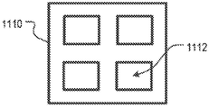
도 11a 내지 도 11e는 본 교시에 따라 제조될 수 있는 복잡한 개방 프레임워크 부품의 실시형태를 도시한다.1A illustrates a towpreg for use with an embodiment of the present invention.
FIG. 1B shows a segment of the towpreg of FIG. 1A that is a linear preform.
Fig. 2a shows a longitudinal section of a first embodiment of the preform of Fig. 1b;
FIG. 2B shows a cross-section of a first embodiment of the preform of FIG. 1B .
Fig. 3a shows a longitudinal section of a second embodiment of the preform of Fig. 1b;
Fig. 3b shows a cross section of a second embodiment of the preform of Fig. 1b;
4 shows an embodiment of an open planar nonlinear preform according to the present invention.
5 shows a first embodiment of a closed planar non-linear preform according to the invention;
6 shows a second embodiment of a closed planar nonlinear preform according to the present invention.
7 shows a third embodiment of a closed planar nonlinear preform according to the present invention.
8 shows an embodiment of an open non-planar area non-linear preform in accordance with the present invention.
9A illustrates a first embodiment of a layup of a preform according to the present teachings.
9B illustrates a second embodiment of a layup of a preform according to the present teachings.
Fig. 9c shows a part formed from the layup of Fig. 9a or 9b;
Fig. 10A shows a segment of the layup of Fig. 9B;
FIG. 10B shows a longitudinal section of a region of a part formed from the segment of the layup shown in FIG. 10A ;
FIG. 10C shows a cross-section along axis AA of FIG. 10B .
FIG. 10D shows a cross-section along the BB axis of FIG. 10B .
FIG. 10E shows an exploded view of the part of FIG. 9C showing sections and parts of the part.
11A-11E illustrate embodiments of complex open framework parts that may be fabricated in accordance with the present teachings.
다음 용어는 본 개시내용 및 첨부된 청구범위에서 사용되기 위해 아래에서 정의된다:The following terms are defined below for use in this disclosure and the appended claims:
ㆍ "섬유 복합물"은 매트릭스 재료 및 섬유 재료의 두 가지 주요 구성요소를 포함하는 재료이다. 섬유 재료(섬유)는 일반적으로 이에 의해서 기여되는 다른 특성 외에도 복합물의 강도에 크게 연관된다. 일반적으로 폴리머 수지로 형성된 매트릭스는 섬유를 둘러싸고 지지하여 섬유의 상대적 위치를 유지하고 마모 및 환경에 의한 공격(environmental attack)을 방지한다. 섬유와 수지의 조합은 시너지 효과를 나타내며, 결과적인 특성은 특정한 섬유, 수지 및 섬유 부피 분율에 의존된다.• A “fiber composite” is a material comprising two main components: a matrix material and a fiber material. The fibrous material (fiber) is generally highly related to the strength of the composite in addition to the other properties contributed thereby. In general, a matrix formed of a polymer resin surrounds and supports the fibers to maintain the relative position of the fibers and prevent abrasion and environmental attack. The combination of fibers and resins exhibits a synergistic effect, and the resulting properties depend on the particular fiber, resin and fiber volume fraction.
ㆍ "섬유"는 섬유 재료의 개별 가닥을 의미한다. 섬유는 직경보다 훨씬 더 큰 길이를 갖는다.• "Fiber" means an individual strand of fibrous material. The fibers have a length that is much greater than their diameter.
ㆍ "매트릭스 재료"는 폴리머 수지, 일반적으로 열가소성 또는 b-스테이지(즉, 부분적으로 경화된) 열경화성 수지이다. 매트릭스 재료는 또한 세라믹일 수 있다.• "Matrix material" is a polymeric resin, usually a thermoplastic or b-stage (ie, partially cured) thermosetting resin. The matrix material may also be ceramic.
ㆍ "공동 정렬된 섬유"는 동일한 방향으로 배향된 복수의 섬유를 지칭한다.• "Co-aligned fibers" refers to a plurality of fibers oriented in the same direction.
ㆍ "토우(tow)"는 "섬유의 다발"을 의미하고, 이러한 용어들은 달리 명시되지 않는 한 본원에서 상호교환 가능하게 사용된다. 토우는 일반적으로 1K 토우, 3K 토우, 6K 토우 등 수천의 섬유 번호로 이용 가능하다. 용어 "필라멘트"는 또한 본원에서 "토우"와 동의어로 사용될 수 있다.• "tow" means "bundle of fibers" and these terms are used interchangeably herein unless otherwise specified. Tows are generally available in thousands of fiber numbers, including 1K tows, 3K tows, and 6K tows. The term “filament” may also be used synonymously with “tow” herein.
ㆍ "프리프레그"는 수지로 함침된 섬유를 의미한다.• "Prepreg" means a fiber impregnated with a resin.
ㆍ "토우프레그" 또는 "프리프레그 토우(Prepreg Tow)"는 수지로 함침된 섬유 다발(즉, 토우)을 의미한다.• "Towpreg" or "Prepreg Tow" means a fiber bundle (ie, tow) impregnated with a resin.
ㆍ "프리폼" 또는 "필라멘트 서브유닛(subunit)"은 토우/토우-프레그의 크기가 정해진 또는 크기가 정해지고 형상화된 부분을 의미하며, 여기서 섬유 다발의 단면은 약 0.25 내지 약 6의 종횡비(폭 : 두께)를 갖는다. 본원에서 사용되기 위해, 용어 프리폼 및 필라멘트 서브유닛은 일반적으로 약 10 내지 약 30의 종횡비(위와 같이, 단면)를 갖는 크기/형상의 "테이프"를 명시적으로 배제한다. 용어, 프리폼 및 필라멘트 서브유닛은 또한, 섬유 및 라미네이트의 시트도 명시적으로 제외한다."Preform" or "filament subunit" means a sized or sized and shaped portion of a tow/tow-preg, wherein the cross-section of the fiber bundle has an aspect ratio (width) of from about 0.25 to about 6. : thickness). As used herein, the terms preform and filament subunits explicitly exclude “tape” of a size/shape that generally has an aspect ratio (cross-section, as above) of from about 10 to about 30. The terms preform and filament subunit also explicitly exclude sheets of fibers and laminates.
ㆍ "연속적인 섬유"는 프리폼/필라멘트 서브유닛의 일 단부로부터 다른 단부까지 연장되는 섬유를 지칭한다. 일부 맥락(즉, 출원인의 다른 특허 출원 중 일부)에서, 연속적인 섬유/연속적인 프리폼은 섬유/다발이 배치되는 몰드의 주요 피처의 길이와 거의 동일한 길이를 갖는 섬유/프리폼을 지칭한다. 당 업계에서 일반적으로 사용되는 바와 같이, 연속적인 섬유는 "?h(chopped) 섬유" 또는 "절단된 섬유"와 구별된다. ?h 섬유 또는 절단된 섬유는 몰드 및 최종 부품에서 랜덤 방향을 갖고, 금형/부품의 어떠한 피처 길이에 대해서 사전 정의된 관계를 갖지 않는다. 본 교시에 따른 섬유-다발 기반 프리폼은 ?h 섬유 또는 절단된 섬유를 포함하지 않는다. • "Continuous fiber" refers to fibers extending from one end of the preform/filament subunit to the other. In some contexts (ie, some of Applicants' other patent applications), continuous fiber/continuous preform refers to a fiber/preform having a length approximately equal to the length of the main feature of the mold in which the fiber/bundle is disposed. As commonly used in the art, continuous fibers are distinguished from “chopped fibers” or “chopped fibers”. ?h Fibers or chopped fibers have a random orientation in the mold and final part, and have no predefined relationship to any feature length of the mold/part. Fiber-bundle based preforms according to the present teachings do not include ?h fibers or chopped fibers.
ㆍ "연속적인 매트릭스"는(예를 들어, 프리폼의, 부품의, 부품의 특정 영역의) 단면 전체에 걸쳐서 균질한 매트릭스를 지칭한다.• "Continuous matrix" refers to a matrix that is homogeneous throughout its cross-section (eg, of a preform, of a part, of a particular area of a part).
ㆍ "격자"는 빈 공간을 교차하고 둘러싸는 직선 세그먼트 또는 만곡된 세그먼트로 구성된 프레임워크를 지칭한다.• "Grid" refers to a framework composed of straight or curved segments intersecting and enclosing an empty space.
ㆍ "약" 또는 "실질적으로"는 명시된 수치 또는 공칭 값에 대해 +/- 20%를 의미한다.• "About" or "substantially" means +/- 20% of the stated numerical or nominal value.
추가 정의는 문맥에 따라 명세서에서 제공된다.Additional definitions are provided in the specification depending on the context.
실시예에서, 또는 달리 지시된 경우를 제외하고, 예를 들어 명세서 및 청구범위에서 사용된 성분의 양을 표현하는 모든 숫자는 모든 경우에 용어 "약"에 의해 수식된 것으로 이해될 것이다. 따라서, 반대로 지시되지 않는 한, 하기 명세서 및 첨부된 청구범위에 기재된 수치 파라미터는 당업자가 이해할 수 있는 방식으로 수득될 원하는 특성에 따라 달라질 수 있는 근사치인 것으로 이해된다. 일반적으로, 이것은 적어도 +/- 20%의 변동을 의미한다. Except in the Examples, or where otherwise indicated, all numbers expressing quantities of ingredients used, for example, in the specification and claims, will be understood as modified in all instances by the term "about." Accordingly, it is understood that, unless indicated to the contrary, the numerical parameters set forth in the following specification and appended claims are approximations which may vary depending upon the desired properties to be obtained in a manner understood by those skilled in the art. In general, this means a variation of at least +/- 20%.
또한, 본원에 언급된 임의의 수치 범위는 이 안에 포함된 모든 하위 범위를 포함하도록 의도된다는 점이 이해되어야 한다. 예를 들어, "1 내지 10"의 범위는 약 1의 언급된 최소 값과 약 10의 언급된 최대 값 사이의, 즉 약 1과 같거나 보다 큰 최소 값, 및 약 10과 같거나 보다 작은 최대 값을 갖는 모든 하위 범위를 포함하도록 의도된다.It should also be understood that any numerical range recited herein is intended to include all subranges subsumed therein. For example, a range of “1 to 10” is between a stated minimum value of about 1 and a stated maximum value of about 10, i.e., a minimum value greater than or equal to about 1, and a maximum value less than or equal to about 10. It is intended to include all subranges with values.
도 1a는 토우프레그(100)를 도시한다. 토우프레그는, 일반적으로 폴리머 수지 매트릭스로 함침된 천의 배수(예를 들어, 1k, 10k, 24k 등)로 제공되는 많은 개별 섬유를 포함한다. 토우프레그는 예를 들어, 원형, 오벌, 트라이로발(trilobal), 다각형 등을 포함하는 다양한 단면 형상 중 하나를 가질 수 있다.1A shows a
토우프레그는 텍사스주 어빙의 Celanese Corporation 등과 같은 공급자로부터 구입되거나, 또는 인발, 압출 또는 공압출과 같은 잘 알려진 프로세스를 통해 현장(on-site)에서 형성될 수 있다. 인발 프로세스에서, 섬유 "토우" 형태의 복수의 섬유는 다이를 통해 당겨지고 압력 및 온도 하에서 폴리머(일반적으로 열가소성 또는 열경화성) 수지로 함침된다. 상기 프로세스는 위에서 언급된 바와 같이 연속적인 매트릭스 재료 내에 매립된 복수의 섬유를 제공한다. Towpregs may be purchased from suppliers such as Celanese Corporation of Irving, Texas, or formed on-site through well-known processes such as drawing, extrusion or coextrusion. In the drawing process, a plurality of fibers in the form of fibrous “tows” are pulled through a die and impregnated with a polymer (usually a thermoplastic or thermoset) resin under pressure and temperature. The process provides a plurality of fibers embedded in a continuous matrix material as mentioned above.
이제 도 1b를 참조하면, 섬유 다발 기반 프리폼(102)은 토우프레그(100)의 세그먼트를 제거함으로써 형성된다. 도 1b에서, 프리폼(102)은 짧은 선형 세그먼트이다. 이것은 본 발명의 실시형태가 지향되는 프리폼들 중 가장 기본적인 실시형태이다. 본 명세서의 후반부에 더 상세히 설명되는 바와 같이, 다른 실시형태에서, 프리폼은 제조되는 부품에 적절하게 비선형 형상, 폐쇄 형태 형상, 3D 형상 및 다층 형상을 포함하는 더 복잡한 형상을 가질 수 있다. 실제로, 이러한 프리폼은, 본 교시에 따른 섬유 강화 부품을 제조하기 위한 "구축 블록(building block)"이다.Referring now to FIG. 1B , a fiber bundle based
프리폼은 일반적으로 폭보다 실질적으로 더 크고 두께보다 실질적으로 더 큰 길이를 갖는다(도 1b는 축척에 따르지 않음). 프리폼의 길이는 제조되는 부품의 속성에 기반하여 결정된다. 프리폼 길이에 대한 주요 영향은 부품의 사이즈이다. 일반적으로, 더 긴 프리폼은 더 긴 연속적인 길이의 섬유를 포함할 수 있기 때문에 임의의 주어진 응용분야에 대해 가능한 가장 긴 프리폼을 사용하는 것이 바람직하다. 주어진 부품에 대해, 더 긴 연속적인 섬유는 일반적으로 더 짧은 길이의 섬유보다 더 강한 부품으로 귀결된다. 따라서, 매우 작은 부품의 경우, 프리폼은 약 5 mm의 길이를 가질 수 있는 한편, 큰 부품(예를 들어, 비행기 날개, 차체 패널 등)의 경우, 프리폼은 수 미터의 길이를 가질 수 있다. 간단히 말해, 프리폼 길이는 응용분야 특이적이다.The preform generally has a length substantially greater than the width and substantially greater than the thickness ( FIG. 1B is not to scale). The length of the preform is determined based on the properties of the part being manufactured. The main influence on preform length is the size of the part. In general, it is desirable to use the longest possible preform for any given application because longer preforms may include fibers of longer continuous lengths. For a given part, longer continuous fibers generally result in a stronger part than shorter length fibers. Thus, for very small parts, the preform can have a length of about 5 mm, while for large parts (eg airplane wings, body panels, etc.) the preform can have a length of several meters. Simply put, the preform length is application specific.
프리폼은, 제조되는 부품에 적합한 임의의 적절한 단면(즉, 폭 및 높이/두께) 치수를 가질 수 있다. 일부 실시형태에서, 프리폼의 폭 및 높이(두께)는 거의 동일하다(예를 들어, 원형 단면, 정사각형 단면 등). 본 발명의 실시형태에서, 프리폼의 단면 형상은 위에서 논의된 토우프레그의 단면 형상에 의해 결정된다. 프리폼의 형상, 높이 및 폭은 길이를 따라 실질적으로 일정하거나, 변할 수 있다.The preform may have any suitable cross-sectional (ie, width and height/thickness) dimensions suitable for the part being manufactured. In some embodiments, the width and height (thickness) of the preforms are approximately the same (eg, circular cross-section, square cross-section, etc.). In an embodiment of the present invention, the cross-sectional shape of the preform is determined by the cross-sectional shape of the towpreg discussed above. The shape, height and width of the preform may be substantially constant or vary along its length.
예를 들어, 몰드 캐비티 내 로봇 장치에 의한 배치를 위해서 프리폼이 쉽게 조작되는 것이 바람직하다. 결과적으로, 프리폼을 형성하는 재료는 사용 온도(일반적으로 약 20℃ 내지 30℃)에서 쉽게 핸들링될 수 있는 상태(예를 들어, 고체, 강성 등)에 있어야 한다. 대안적으로, 프리폼의 온도는 핸들링을 용이하게 하기 위해 필요에 따라 변경될 수 있다.For example, it is desirable for the preform to be easily manipulated for placement by a robotic device in a mold cavity. As a result, the material from which the preform is formed must be in a state (eg, solid, rigid, etc.) that can be easily handled at the temperature of use (typically between about 20° C. and 30° C.). Alternatively, the temperature of the preform may be varied as needed to facilitate handling.
프리폼 조성. 프리폼의 조성/내부 구조는 공급되는 토우프레그의 것과 동일하다는 점이 이해될 것이다. Preform composition. It will be appreciated that the composition/internal structure of the preform is the same as that of the supplied towpreg.
섬유와 관련하여, 토우프레그(100)의 개별 섬유는, 일반적으로, 그러나 반드시 그런 것은 아닌, 약 1 내지 약 100 마이크론의 범위 내에 있는 임의의 직경을 가질 수 있다. 개별 섬유는, 프로세싱을 용이하게 하거나, 바인더의 접착을 촉진하거나, 섬유의 자기 접착을 최소화하거나, 특정 특성(예를 들어, 전기적 전도도 등)을 부여하기 위해 사이징(sizing)과 같은 외부 코팅을, 한정됨 없이, 포함할 수 있다.With respect to fibers, the individual fibers of the
각각의 개별 섬유는 중실 또는 중공 코어일 수 있다. 각각의 개별 섬유는 단일 재료 또는 다수의 재료(예를 들어, 아래 나열된 재료들)로 형성될 수 있거나, 또는 자체적으로 복합물일 수 있다. 예를 들어, 개별 섬유는 전기 전도성 재료, 전기 절연 재료, 열 전도성 재료 또는 열 절연 재료와 같은 제2 재료로 코팅된(제1 재료의) 코어를 포함할 수 있다.Each individual fiber may be a solid or hollow core. Each individual fiber may be formed of a single material or multiple materials (eg, the materials listed below), or may itself be a composite. For example, the individual fibers may include a core coated (of a first material) with a second material, such as an electrically conductive material, an electrically insulating material, a thermally conductive material, or a thermally insulating material.
조성 측면에서, 각각의 개별 섬유는 예를 들어, 한정됨 없이, 탄소, 유리, 천연 섬유, 아라미드, 붕소, 금속, 세라믹, 폴리머 필라멘트 등일 수 있다. 금속 섬유의 비제한적인 예는 강철, 티타늄, 텅스텐, 알루미늄, 금, 은, 상술된 것 중 임의의 것의 합금, 및 형상 기억 합금을 포함한다. "세라믹"은 모든 무기 재료 및 비금속 재료를 지칭한다. 세라믹 섬유의 비제한적인 예는 유리(예를 들어, S-유리, E-유리, AR-유리 등), 석영, 금속 산화물(예를 들어, 알루미나), 알루미노 규산염, 규산 칼슘, 암면, 질화 붕소, 실리콘 카바이드 및 상술된 것 중 임의의 것의 조합을 포함한다. 또한, 탄소 나노튜브가 사용될 수 있다. 개별 프리폼 내에서, 모든 섬유는 일반적으로 동일한 조성을 갖는다.In terms of composition, each individual fiber can be, for example, without limitation, carbon, glass, natural fiber, aramid, boron, metal, ceramic, polymer filament, or the like. Non-limiting examples of metal fibers include steel, titanium, tungsten, aluminum, gold, silver, alloys of any of the foregoing, and shape memory alloys. "Ceramic" refers to all inorganic and non-metallic materials. Non-limiting examples of ceramic fibers include glass (eg, S-glass, E-glass, AR-glass, etc.), quartz, metal oxides (eg, alumina), aluminosilicate, calcium silicate, rock wool, nitride boron, silicon carbide, and combinations of any of the foregoing. Also, carbon nanotubes may be used. Within an individual preform, all fibers generally have the same composition.
매트릭스 재료와 관련하여, 열 및/또는 압력 하에서 자체적으로 본딩되는 임의의 폴리머수지(열가소성 또는 열경화성)가 사용될 수 있다. 본 발명의 실시형태와 관련하여 유용한 예시적인 열가소성 수지는, 한정됨 없이, 아크릴로니트릴 부타디엔 스티렌(ABS), 나일론, 폴리아릴에테르케톤(PAEK), 폴리부틸렌 테레프탈레이트(PBT), 폴리카보네이트(PC) 및 폴리카보네이트-ABS(PC-ABS), 폴리에테르에테르케톤(PEEK), 폴리에테르이미드(PEI), 폴리에테르 설폰(PES), 폴리에틸렌(PE), 폴리에틸렌 테레프탈레이트(PET), 폴리페닐렌 설파이드(PPS), 폴리페닐설폰(PPSU), 폴리인산(PPA), 폴리프로필렌(PP), 폴리설폰(PSU), 폴리우레탄(PU), 폴리염화비닐(PVC)을 포함한다. 예시적인 열경화성 수지는 에폭시이다. 일부 실시형태에서, 세라믹이 매트릭스로서 사용될 수 있다.As for the matrix material, any polymer resin (thermoplastic or thermosetting) that bonds to itself under heat and/or pressure may be used. Exemplary thermoplastic resins useful in connection with embodiments of the present invention include, but are not limited to, acrylonitrile butadiene styrene (ABS), nylon, polyaryletherketone (PAEK), polybutylene terephthalate (PBT), polycarbonate (PC ) and polycarbonate-ABS (PC-ABS), polyetheretherketone (PEEK), polyetherimide (PEI), polyether sulfone (PES), polyethylene (PE), polyethylene terephthalate (PET), polyphenylene sulfide (PPS), polyphenylsulfone (PPSU), polyphosphoric acid (PPA), polypropylene (PP), polysulfone (PSU), polyurethane (PU), polyvinyl chloride (PVC). An exemplary thermosetting resin is an epoxy. In some embodiments, a ceramic may be used as the matrix.
특정 폴리머 수지의 사용에 대한 적합성은, 적어도 부분적으로, 제조되는 부품의 요구 사항에 의존된다. 이러한 요구 사항은 부품의 희망 속성/특성/성질(예를 들어, 미학적, 밀도, 내식성, 열적 성질 등)을 포함할 수 있다.The suitability of a particular polymeric resin for use depends, at least in part, on the requirements of the part being manufactured. These requirements may include desired properties/properties/properties (eg, aesthetics, density, corrosion resistance, thermal properties, etc.) of the part.
폴리머 수지뿐만 아니라, 매트릭스 재료는 예를 들어, 제한 없이, 충전제, 접착 촉진제, 유변학 조절제, 착색제 및 상술된 것의 임의의 조합과 같은 다른 성분을 포함할 수 있다.In addition to the polymer resin, the matrix material may include other ingredients such as, for example, without limitation, fillers, adhesion promoters, rheology modifiers, colorants, and any combination of the foregoing.
필러의 유형과 양은 인장 강도, 연신율, 열 안정성, 저온 유연성, 내화학성, 저밀도, 전기 전도도, 열 전도도, EMI/RFI 차폐, 정전기 소산성, 또는 상술된 것의 조합과 같은 희망 성질을 얻도록 선택될 수 있다. 적합한 충전제의 비제한적인 예는, 실리카 및 탄산칼슘과 같은 무기 충전제, 열가소성 비드와 같은 유기 충전제, 금속, 흑연 및 그래핀과 같은 전기 전도성 충전제, 및 열팽창성 마이크로 캡슐과 같은 저밀도 충전제를 포함한다. 충전제는 비드, 입자, 분말, 소편장(platelet), 시트 또는 플레이크와 같은 임의의 적합한 형태를 가질 수 있다.The type and amount of filler may be selected to obtain desired properties, such as tensile strength, elongation, thermal stability, low temperature flexibility, chemical resistance, low density, electrical conductivity, thermal conductivity, EMI/RFI shielding, static dissipation, or a combination of the above. can Non-limiting examples of suitable fillers include inorganic fillers such as silica and calcium carbonate, organic fillers such as thermoplastic beads, electrically conductive fillers such as metals, graphite and graphene, and low density fillers such as thermally expandable microcapsules. The filler may have any suitable form, such as beads, particles, powders, platelets, sheets or flakes.
일부 실시형태에서, 충전제는 프리폼의 단부들 사이에서 완전히 연장되지 않는 비정렬 섬유 및/또는 불연속적인 섬유를 포함한다. 이러한 비정렬된 섬유는 촙 섬유, 밀링된 섬유 또는 이들의 조합을 포함할 수 있다. 비정렬된 섬유는 예를 들어, 섬유 직물, 꼬인 섬유 등을 포함하는 복수의 비정렬된 연속적인 섬유를 포함할 수 있다.In some embodiments, the filler comprises non-aligned fibers and/or discontinuous fibers that do not fully extend between the ends of the preform. Such unaligned fibers may include chopped fibers, milled fibers, or combinations thereof. Unaligned fibers may include a plurality of unaligned continuous fibers including, for example, fibrous fabrics, twisted fibers, and the like.
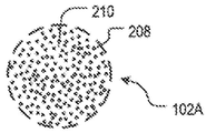
프리폼 내부 구조. 프리폼은 균일 또는 비균일 내부 구조를 가질 수 있다. 도 2a 및 도 2b는 도 1a/1b의 토우프레그(100)의 제1 실시형태의 프리폼(102A)을 도시한다. 도 2a 및 도 2b에 도시된 실시형태에서, 프리폼(102A)은 균일한 내부 구조를 갖는다(왜냐하면 이것을 공급하는 토우프레그가 균일한 내부 구조를 갖기 때문). Preform internal structure. The preform may have a uniform or non-uniform internal structure. 2A and 2B show a
도 2a는 프리폼(102A)의 길이 방향 단면을 도시한다. 프리폼(102A)은 선형이며, 이는 섬유 다발 기반 프리폼의 가장 기본적인 구현이다. 프리폼(102A)은 복수의 섬유(208)를 포함한다. 이 섬유들은, 프리폼(102A)의 제1 단부(204A)로부터 제2 단부(206A)로 연장되기 때문에 "연속적"이다. 또한, 섬유(208)는 모두 동일한 방향으로 배향되기 때문에 "공동 정렬"된다. 프리폼(102A)은 또한, 섬유(208)를 둘러싸고 적시는 폴리머 수지 매트릭스(210)를 포함한다.2A shows a longitudinal cross-section of the
도 2b는 프리폼(102A)의 횡단면을 도시한다. 이러한 실시형태에서, 복수의 공동 정렬된 섬유(208)는 프리폼(102A)의 횡단면에 걸쳐(즉, 방사상으로) 실질적으로 균일하게 분포된다.2B shows a cross-section of
도 3a 및 도 3b는 도 1a/도 1b의 토우프레그(100)의 제2 실시형태의 프리폼(102B)을 도시한다. 도 3a 및 도 3b에 도시된 실시형태에서, 프리폼(102B)은 비균일한 내부 구조를 갖는다(왜냐하면 이것을 공급하는 토우프레그가 비균일한 내부 구조를 갖기 때문). 3A and 3B show a preform 102B of a second embodiment of the
도 3a는 프리폼(102B)의 길이 방향 단면을 도시한다. 프리폼(102A)과 같이, 프리폼(102B)은 프리폼(102B)의 단부들(204B 및 206B) 사이에서 완전히 연장되기 때문에 연속적인 복수의 섬유(208)를 포함한다. 프리폼(102B)의 섬유는 또한, 프리폼(102A)에서와 같이 공동 정렬된다.3A shows a longitudinal cross-section of the preform 102B. Like
도 3a를 계속 참조하면서, 이제 도 3b를 참조하면, 섬유(208)가 프리폼(102B)에서 방사상으로 균일하게 분포되지 않는다는 점을 알 수 있다. 특히, 섬유(208)는 프리폼(102B)의 매트릭스(210)로 매립된 밴드로 배열된다. 즉, 프리폼(102B)은 방사상 방향으로 비균일한 조성을 갖는다. 일부 다른 실시형태에서, 프리폼은 섬유의 다른 비균일 분포를 가질 수 있다.With continued reference to FIG. 3A , referring now to FIG. 3B , it can be seen that the
프리폼 외부 아키텍처. 도 4 내지 도 8은 도 2a/도 2b 및 도 3a/도 3b의 프리폼(102A 및 102B)의 단순한 선형 아키텍처에 더하여 여러 프리폼 아키텍처를 도시한다.Freeform external architecture. 4-8 show several preform architectures in addition to the simple linear architecture of
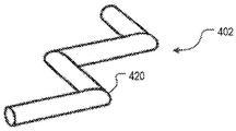
도 4는 본 발명에 따른 개방형 평면적 비선형 프리폼인 프리폼(402)을 도시한다. 프리폼(402)은 하나 이상의 굴곡부(420)를 포함하기 때문에 비선형이다. 프리폼(402)은 굴곡부들이 동일한 평면 내에 있기 때문에 평면적이다. 각각의 굴곡부(420)는 0° <굴곡부 각도(420) < 180° 범위의 각도로부터 독립적으로 선택된 각도를 가질 수 있다.4 shows a
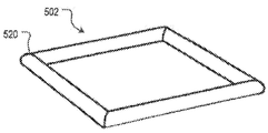
프리폼(402)과 같은 비선형 프리폼은 내부의 매트릭스 재료의 연화점 위로 토우-프레그의 일 부분을 가열한 다음, 예를 들어, 자동 벤딩 도구를 통해 토우-프레그를 벤딩함으로써 형성될 수 있다. 적절한 수의 굴곡부가 만들어진 후, 토우-프레그는 사이즈가 조정되어/절단되어, 프리폼을 생성한다. 프리폼을 제조하는 방법은 미국 특허 출원 제15/612,720호 및 제16/600,131호에 개시되며, 이들은 본원에 참조로 포함된다. 도 5는 본 발명에 따른 폐쇄형 평면적 비선형 프리폼인 프리폼(502)을 도시한다. 폐쇄형 프리폼은 일반적으로, 두 단부가 서로 인접하게 위치되어, 둘러싸인 영역을 획정하도록 벤딩된, 단일 길이의 사이즈가 조정된 토우-프레그를 포함한다. 일부 실시형태에서, 두 개의 단부는, 예를 들어, 접착제 또는 열적 본딩을 통해 함께 택킹(tack)된다. (프리폼(402)은 두 개의 단부가 서로 인접하지 않고 밀폐된 영역을 획정하지 않기 때문에 "개방형"이다.) 프리폼(502)은 네 개의(즉, 하나 이상의) 굴곡부(520)를 포함하기 때문에 비선형이다. 프리폼(502)은 굴곡부들이 동일한 평면 내에 있기 때문에 평면적이다.A non-linear preform, such as
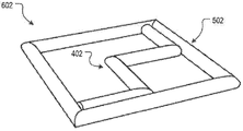
도 6은 프리폼(402) 및 프리폼(502)의 조합인 프리폼(602)을 도시한다. 프리폼(602)은 평면적이고 비선형이고, 개방형 요소 및 폐쇄형 요소를 모두 포함한다. 프리폼(602)은 프리폼들(402 및 502)을 형성한 다음 함께 택킹함으로써 제조될 수 있다.6 shows a
프리폼(502, 602, 702)과 같은 "폐쇄형"인 것을 특징으로 하는 프리폼은 일반적으로, 그러나 반드시 그런 것은 아니지만, 추가적으로 또는 대안적으로, "개방 프레임워크" 또는 "개방 부피부" 프리폼인 것을 특징으로 한다. 일부 실시형태에서, 이러한 개방형 프레임워크 프리폼은 도 11a 내지 도 11e와 관련하여 본 개시내용에서 후술되는 바와 같이 "개방형 프레임워크" 부품을 제조하기 위해서 사용된다. Preforms characterized as being "closed", such as
도 7은, 폐쇄형이고, 평면적이고 비선형인 프리폼(702)을 도시한다. 프리폼(702)은 적층된 요소들(730)을 포함하지만, 그럼에도 불구하고 모든 굴곡부가 동일한 평면 또는 평행 평면들 내에 있기 때문에 평면적인 것으로 간주된다. 프리폼(702)은, 각각 외측 정사각형 요소(732) 및 내측 정사각형 요소(734)를 포함하는 요소(730)의 두 개의 사례를 포함한다.7 shows a closed, planar,
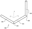
도 8은 개방형 비평면형적 비선형 프리폼인 프리폼(802)을 도시한다. 프리폼(802)은 적어도 하나의 굴곡부가 다른 굴곡부에 대해 평면외이기 때문에 비평면적인 것으로 간주된다. 특히, 세그먼트(840)와 세그먼트(844) 사이의 굴곡부(842)는 y-x 평면에 있고(즉, 굴곡부는 y-x 평면에 속하는 두 개의 세그먼트를 생성함), 세그먼트(844)와 세그먼트(848) 사이의 굴곡부(846)는 x-z 평면 내에 있다. 이러한 평면들은 본원에서 서로에 대해 "평면외"인 것으로 정의된다. 프리폼(702)과 관련하여 위에서 암시되고, 여기에서 명시된 바와 같이, 특징 "평면외"는 "굴곡부"를 포함하는 층상 요소 또는 적층형 요소를 제외하며, 이러한 적층형 요소들은 서로 실질적으로 평행하다(평행 평면 내에 있음).8 shows a
프리폼(802)에서, 굴곡부들은 서로 직교하는 평면들 내에 있다. 그러나, 일부 다른 실시형태에서, 굴곡부들은 서로에 대해 평면외이지만, 서로 직교하지 않는 평면들 내에 있다. 도 4의 프리폼(402)에 대해 개시된 바와 같이, 각각의 굴곡부에 대한 굴곡부 각도는 개별적으로 선택될 수 있다. 따라서, 굴곡부(846)는 0°보다 크고 180°보다 작은 임의의 각도를 가질 수 있다.In the
도 4 내지 도 8에 도시된 프리폼은 하나의 0이 아닌 벡터 성분(즉, x, y 또는 z 축을 따라 그리고 x-y, z-x 또는 y-z 평면 내)에 의해 정의된 임의의 주어진 굴곡부를 묘사하지만, 일부 다른 실시형태에서, 굴곡부는 0이 아닌 x, y 또는 z 벡터 구성요소의 임의의 조합으로 정의될 수 있다.The preforms shown in Figures 4-8 depict any given bend defined by one non-zero vector component (i.e., along the x, y or z axis and in the xy, zx or yz plane), but some other In embodiments, a bend may be defined as any combination of non-zero x, y, or z vector components.
일부 다른 실시형태에서, 프리폼은 비평면적 비선형이고 폐쇄형이다. 또한, 비평면적 비선형 프리폼은 비평면적 비선형 요소 및 평면적 비선형 요소를 포함할 수 있다. 이러한 프리폼의 일 예는, 예를 들어, 도 5의 프리폼(502)과 도 8의 프리폼(802)을 결합한 프리폼이다.In some other embodiments, the preform is non-planar non-linear and closed. Further, the non-planar non-linear preform may include non-planar non-linear elements and planar non-linear elements. An example of such a preform is, for example, a preform combining the
본 방법에 따른 압축 성형. 앞서 언급된 바와 같이, 본 교시에 따르면, 섬유 다발 기반 프리폼은 압축 성형을 통해 부품을 제조하기 위해서 사용된다. 보다 구체적으로, 본 교시에 따르면, 매트릭스 재료가 유동되는 "즉, 용융 유동" 정도까지 연화되게끔 하도록, 몰드 캐비티에 두 개 이상의 이러한 프리폼을 배치하고, 몰드 캐비티를 폐쇄하여 가압하고, 몰드 캐비티의 내용물의 온도를 상승시킴으로써, 부품이 제조된다. 이와 같이 가해진 압력과 온도 하에서, 두 개 이상의 프리폼은 통합되고, 냉각 후 완성된 부품이 생성된다.Compression molding according to the method. As mentioned above, in accordance with the present teachings, fiber bundle based preforms are used to manufacture parts through compression molding. More specifically, according to the present teachings, two or more such preforms are placed in a mold cavity, closed and pressed against the mold cavities, to soften the matrix material to the extent of "i.e., melt flow," to which it flows. By raising the temperature of the contents, the part is manufactured. Under this applied pressure and temperature, the two or more preforms are consolidated and, after cooling, a finished part is produced.
잘 알려진 바와 같이, 압축 성형은 일반적으로, 적어도 약 100 psi의 압력에서 수행된다. 프로세스에 대한 온도 요건은 사용된 매트릭스 재료의 함수이다. 예를 들어, 열가소성 수지를 포함하는 매트릭스의 경우, 온도는 수지가 유동될 수 있도록 수지의 유리 전이 온도를 만족하거나 초과해야 지만, 분해 온도 이하로 유지되어야 한다. B-스테이지 열경화성 수지 또는 B-스테이지 세라믹을 포함하는 매트릭스의 경우, 매트릭스 재료는 유동될 수 있을 만큼 충분히 가열되어야 하고, 또한 공반응물의 반응 온도를 만족하거나 초과해야 한다.As is well known, compression molding is generally performed at a pressure of at least about 100 psi. The temperature requirement for the process is a function of the matrix material used. For example, in the case of a matrix comprising a thermoplastic resin, the temperature must meet or exceed the glass transition temperature of the resin so that the resin can flow, but must remain below the decomposition temperature. In the case of a matrix comprising a B-stage thermoset or B-stage ceramic, the matrix material must be heated sufficiently to allow it to flow, and must also meet or exceed the reaction temperature of the co-reactant.
앞서 언급된 바와 같이, 본 교시에 따르면, 두 개 이상의 섬유 다발 기반 프리폼이 몰드 캐비티에서 특정 배열 및/또는 배향으로("레이업") 배치된다. 배열/배향 세부사항은 원하는 전체 부품 성질(예를 들어, 기계적 성질, 미관 등) 또는 부품의 특정 영역의 성질에 적어도 부분적으로 기반한다. 레이업으로 배치하는 동안, 프리폼은 제조된 형상을 유지한다. 이러한 특성은 섬유를 특정 프리폼으로부터 부품의 특정 부피 영역으로 지향시키는 것을 용이하게 한다.As noted above, in accordance with the present teachings, two or more fiber bundle based preforms are disposed in a particular arrangement and/or orientation (“layup”) in a mold cavity. The arrangement/orientation details are based, at least in part, on the desired overall part properties (eg, mechanical properties, aesthetics, etc.) or the properties of specific regions of the part. During placement into the layup, the preform retains its manufactured shape. This property facilitates directing the fibers from a specific preform to a specific volume area of the part.
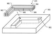
도 9a 및 도 9b는 압축 성형을 통해 섬유 복합물 부품(972)(도 9c)을 제조하는 데 사용되기 위한, 두 개의 예시적인 섬유 다발 기반 프리폼 레이업(958 및 970)뿐만 아니라, 몰드 캐비티(952)를 갖는 암형 몰드 하프(half)(950)를 각각 도시한다.9A and 9B show two exemplary fiber bundle based
도 9a에 도시된 레이업(958)은 다음을 포함한다: (i) 다각형(정사각형) 횡단면을 가지며 각각 세 개의 프리폼으로 구성된 두 개의 층으로 배열된 여섯 개의 선형 프리폼(954), 및 (ii) 원형 횡단면을 가지며 각각 세 개의 프리폼으로 구성된 두 개의 층으로 배열된 여섯 개의 선형 프리폼(956). 이 두 그룹의 프리폼은 서로 직각으로 배향되며, 프리폼(956) 각각의 일 단부가 적층된 프리폼들(954) 중 두 개의 프리폼의 일 측부에 접한다.The
도 9b에 도시된 레이업(970)은 레이업(958)보다 더 복잡한 배열체이고, 다음을 포함한다: (i) 두 개의 적층된 "L" 형상(비선형) 프리폼(960), (ii) 각각 두 개의 프리폼으로 구성된 두 개 층으로 구성된 네 개의 선형 프리폼(962), (iii) 하나의 선형 프리폼(964), (iv) 각각 두 개의 프리폼으로 구성된 두 개의 층으로 구성된 네 개의 선형 프리폼(966), 및 (v) 각각 두 개의 프리폼으로 구성된 두 개의 레이어로 구성된 두 개의 선형 프리폼(968). 프리폼들(966 및 968)은 프리폼(964)의 길이의 약 절반이다. 이러한 상이한 레이업은 부품이 사용 중에 겪는 힘의 결과로서 부품의 주어진 부피 영역에서 발생되는 응력의 함수로서 사용될 수 있다.The
도시된 두 개의 실시형태 각각에서, 프리폼은 몰드 캐비티(952)의 형상과 일치되는 레이업(958 또는 970)을 형성하기 위해 "L"의 형상으로 배열된다. 일부 실시형태에서, 레이업은 캐비티(952)에 프리폼을 하나씩 추가함으로써 형성되어, 레이업이 캐비티 내에 형성된다. 일부 다른 실시형태에서, 프리폼의 일부 또는 전부는 캐비티(952) 안으로 배치되기 전에 함께 택킹되어 "프리폼 장전물(charge)"을 형성한다. 모든 프리폼이 프리폼 장전물 안으로 조립되는 실시형태에서, 레이업(이후에 프리폼 장전물과 동의어임)이 조립된 다음 단일 유닛으로서 몰드 캐비티 안에 배치된다.In each of the two embodiments shown, the preforms are arranged in the shape of an “L” to form a
몰드 내에 배치된 각각의 프리폼의 조성, 내부 구조 및 외부 아키텍처는 일반적으로 제조되는 부품의 희망 성질을 달성하기 위해 적절하게 개별적으로 선택될 수 있다. 예를 들어, 레이업에서 복수의 프리폼이 주어지면, 적어도 하나의 프리폼은 다음의 비제한적인 방식으로 다른 프리폼과 상이할 수 있다:The composition, internal structure, and external architecture of each preform disposed within the mold can generally be individually selected as appropriate to achieve the desired properties of the part being manufactured. For example, given a plurality of preforms in a layup, at least one preform may differ from another preform in the following non-limiting manner:
ㆍ 서로 다른 매트릭스 재료(예를 들어, 두 개의 서로 다른 열가소성 수지들, 서로 다른 충전제들 등);• different matrix materials (eg, two different thermoplastics, different fillers, etc.);
ㆍ 서로 다른 섬유 유형(예를 들어, 탄소 섬유 대 유리 등);• different fiber types (eg carbon fiber versus glass, etc.);
ㆍ 서로 다른 섬유 부피 분율;ㆍ different fiber volume fractions;
ㆍ 섬유의 균일한 분포 대 비균일한 분포;• Uniform versus non-uniform distribution of fibers;
ㆍ 선형 대 비선형;• Linear versus non-linear;
ㆍ 평면 대 비평면.• Flat to non-planar.
매트릭스 재료는 레이업에서 하나의 프리폼과 다음 프리폼에서 다른 만큼, 이러한 상이한 매트릭스 재료들은 서로 호환 가능해야 한다. 본 문맥에서, "호환 가능"은 서로 다른 매트릭스 재료들이 서로 본딩될 것임을 의미한다.As the matrix material differs from one preform to the next in a layup, these different matrix materials must be compatible with each other. In this context, "compatible" means that different matrix materials will be bonded to each other.
부품 내부 구조. 본 발명의 실시형태에 따른 상술된 바와 같은 서로 다를 수 있는 섬유 다발 기반 프리폼들의 선택적 위치결정은 부품의 상이한 영역들에서 상이한 재료 성질들을 갖는 부품을 제조하는 능력을 제공한다. 이것은, 임의의 다른 고려 사항 중에서, 부품 상의 사용 중 부하가 부품의 상이한 영역들에서 종종 달라 지며, 내부에서 상이한 응력 벡터로 발생되므로, 매우 유리하다. 또한, 부품의 특정 영역에서 특정 강성 또는 원하는 전기적 특성에 대한 설계는 상술된 내용에 의해 용이하게 된다.Part internal structure. The selective positioning of fiber bundle based preforms, which may be different from each other, as described above in accordance with embodiments of the present invention provides the ability to manufacture parts with different material properties in different regions of the part. This is very advantageous, as the in-use loads on the part often vary in different areas of the part and are generated with different stress vectors inside, among any other considerations. In addition, the design for a specific stiffness or desired electrical property in a specific area of a component is facilitated by the foregoing.
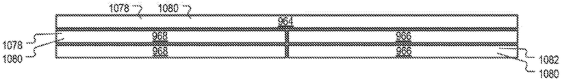
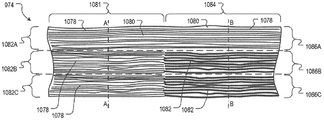
본 교시에 따라 형성된 부품은 두 개 이상의 "섹션"을 포함하는 것으로 간주된다. 도 10b는 도 9c의 부품(972)의 아암(974)의 세그먼트를 통한 길이 방향 단면을 도시한다. 이 세그먼트는 두 개의 이러한 섹션을 갖는다: 섹션(1081) 및 섹션(1084). 부품의 다양한 섹션은 서로 인접하여 부품을 형성하지만, 이러한 섹션은 부품의 외부 또는 내부 검사 시 서로 분리된 것으로서 반드시 식별 가능하지는 않다. 즉, 인접한 섹션들은, 일 섹션을 인접 섹션으로부터 분리하는 구별되는 인터페이스가 있지 않을 수 있다는 의미에서 연속적일 수 있다. 예를 들어, 이것은, 인접한 섹션들의 매트릭스 재료가 동일하고 인접한 섹션들의 섬유들이 동일하지 않을 때 발생될 것이다. 인터페이스가 쉽게 식별 가능한지 여부에 관계 없이, "섹션"의 개념은 교육적 목적을 위해서 유용하고, 본원에서 균일한 조성을 갖는(부품의) 부피부를 지칭하기 위해서 사용된다. 즉, 주어진 섹션의 길이를 따라 임의의 위치에서 취해진 횡단면은 실질적으로 동일한 섬유 및 매트릭스 조성/분포/정렬을 나타낼 것이다.A part formed in accordance with the present teachings is considered to include two or more “sections”. FIG. 10B shows a longitudinal section through a segment of
본 교시에 따르면, 각각의 섹션은 적어도 하나의 "부분"을 포함한다. 다시 도 10b를 참조하면, 섹션(1081)은 부분들(1082A, 1082B 및 1082C)로 구성되고, 섹션(1084)은 부분들(1086A, 1086B 및 1086C)로 구성된다. "부분"은 특정 프리폼으로부터 유래된 부품의 부피부를 지칭한다. 즉, 프리폼은 주어진 부분에 대한 섬유 및 매트릭스 재료의 공급원이다. 따라서, 예를 들어, 일 섹션이 두 개의 프리폼으로부터 유래된 경우, 이 섹션은 두 개의 부분을 포함하는 것으로 간주된다. 마찬가지로, 섹션이 세 개의 프리폼으로부터 유래된 경우, 이 섹션은 세 개의 부분 등을 포함하는 것으로 간주된다. 이러한 실시형태에서, 섹션의 각각의 부분의 조성은 따라서, 섹션이 유래된 프리폼의 조성에 의해 결정된다.In accordance with the present teachings, each section includes at least one “portion”. Referring again to FIG. 10B ,
도 10a 및 도 10b의 비교에 의해 이해되는 바와 같이, 프리폼들과 부분들 사이에 반드시 일대일 대응이 있는 것은 아니다. 도 10a는 도 9b의 레이업(970)의 세그먼트를 도시한다. 세그먼트 내의 프리폼은 부품(972)의 아암(974)을 형성하는 섬유 및 매트릭스 재료의 일부의 공급원이다. 레이업의 이러한 세그먼트는 프리폼(964), 두 개의 적층된 프리폼(968) 및 두 개의 적층된 프리폼(966)을 포함한다. 프리폼(964)은 프리폼들(966 및 968)의 상부 상에 배치된다. 프리폼(964 및 968)은 제1 섬유 유형(1078)을 포함하고, 프리폼(966)은 제2 섬유 유형(1082)을 포함한다. 이 실시예에서, 모든 프리폼은 동일한 매트릭스 재료(1080)를 포함하는 것으로 가정된다. 일부 다른 실시형태에서, 매트릭스 재료가 서로 양립할 수 있는 한, 상이한 프리폼들(및 상이한 부분들)의 매트릭스 재료는 다를 수 있다. 도 10b의 축척(특히, 두께)이 도 10a에 비해 확대되었다는 점이 주의된다.There is not necessarily a one-to-one correspondence between the preforms and the parts, as will be understood by the comparison of FIGS. 10A and 10B . FIG. 10A shows a segment of
프리폼(964)으로부터의 공동 정렬된 섬유(1078)는 섹션(1081)의 부분(1082A) 및 섹션(1084)의 부분(1086A) 모두에서 나타난다. 여전히 섹션(1081)을 참조하면, "상측" 프리폼(968)으로부터의 공동 정렬된 섬유(1078)가 부분(1082B)에 나타나고, "하측" 프리폼(968)으로부터의 공동 정렬된 섬유(1078)가 부분(1082C)에 나타난다.
그리고 섹션(1084)에서, "상측" 프리폼(966)으로부터의 공동 정렬된 섬유(1082)가 부분(1086B)에 나타나고 "하측" 프리폼(966)으로부터의 공동 정렬된 섬유(1082)가 부분(1086C)에 나타난다. 매트릭스는 섹션들(1081 및 1084) 전반에 걸쳐서 연속적이다.And in
도 10a 및 도 10b로부터 명백한 바와 같이, 섹션의 각각의 부분의 길이는 이 섹션에 섬유를 기여하는 프리폼의 길이와 반드시 일치되지 않는다(섹션(1081)의 부분(1082A)의 길이를 프리폼(964)의 길이와 비교함). 또한, 프리폼의 두께 또는 폭은 반드시 부분의 두께 또는 폭과 일치되지 않을 것이다. 그러나 일 부분의 형상은 프리폼의 형상에 의해 영향을 받을 것이다. "섹션"의 상황과 유사하게, 인접된 "부분들" 사이의 인터페이스는 식별 가능하거나 식별 가능하지 않을 수 있다.As is apparent from FIGS. 10A and 10B , the length of each portion of the section does not necessarily match the length of the preform that contributes the fibers to that section (preform 964 by the length of
섹션은 인접한 섹션과 동일한 조성 또는 상이한 조성을 가질 수 있다. 후자의 상황과 관련하여, 섹션으로부터 섹션으로, 조성은 매트릭스 재료 조성, 섬유 조성, 함량, 및/또는 섬유 분포뿐만 아니라 다른 조성 변수(들) 관점에서 변할 수 있다. 또한, 인접된 섹션들은 동일하거나 서로 다른 섬유 정렬을 가질 수 있다.A section may have the same composition or a different composition as an adjacent section. With respect to the latter situation, from section to section, composition may vary in terms of matrix material composition, fiber composition, content, and/or fiber distribution, as well as other composition variable(s). Also, adjacent sections may have the same or different fiber alignments.
섹션(1081)의 조성은 섹션(1084)의 조성과 다르다. 특히, 섹션(1081)의 부분들(1082B 및 1082C)은 섬유(1078)를 포함하는 반면, 섹션(1084)의 부분들(1086B 및 1086C)은 섬유(1082)를 포함한다. 이것은 도 10b의 축 A-A 및 축 B-B를 따른 각각의 횡단면을 도시하는 도 10c 및 도 10d로부터 더욱 입증된다. 섹션(1081)의 임의의 곳에서 취해진 횡단면은 도 10c에 도시된 바와 같이 나타날 것이다. 유사하게, 섹션(1084)의 임의의 곳에서 취해진 횡단면은 도 10d에 도시된 바와 같이 나타날 것이다. 그러나, 섹션들(1081 및 1084) 사이의 인터페이스 영역의 횡단면은 도 10c 및 도 10d에 나타난 횡단면과 다소 다르게 보일 수 있다.The composition of
도 10b에 도시된 바와 같이 "수직" 방향 및 "길이" 방향으로 연장되는 것에 추가하여, 일 섹션이 "횡" 방향으로도 연장될 수 있다는 점이 이해될 것이다. 도 10b의 맥락에서, 이것은, 예를 들어, 부분들(1082A, 1082B, 1082C)에 인접하고 "페이지 안으로" 연장되는 추가 부분들을 포함할 것이다. 이것은 도 10e에서 더 구체적으로 묘사된다.It will be appreciated that in addition to extending in the “vertical” and “longitudinal” directions as shown in FIG. 10B , a section may also extend in a “transverse” direction. In the context of FIG. 10B , this would include, for example, additional portions adjacent to
도 10e는 부분(972)의 "분해도"를 섹션별로 도시한다. 섹션의 지정은, 어느 정도, 임의적으로, 위에 제공된 정의에 종속된다. 그러나, 기술어로서 "섹션" 및 "부분"의 사용은 본 발명의 실시형태들을 설명하고 정의하는 것과 관련하여 유용한 교육적 도구를 제공하고, 종래 기술의 부품들과 본 교시에 따라 만들어진 부품들 사이의 차이점을 강조하는 역할을 한다.10E shows an “exploded view” of
도 10e에 도시된 실시형태에서, 다섯 개의 "섹션"(1081, 1084, 1088, 1092 및 1098)은 부품(1072)에 대해 정의된다. 섹션(1081 및 1084)은 도 9b 및 도 10a 내지 도 10d와 관련하여 설명되었다. 도 10e는, 섹션(1081)이 부분들(1082D 및 1082E)을 포함하고 섹션(1084)이 부분들(1086D 및 1086E)을 포함한다는 점을 추가적으로 나타내며, 이 부분들은 도 10b에서 각각의 섹션에 포함되는 것으로서 도시되지 않았다. 도 9b를 참조하면, 적어도 추가 부분(1086D 및 1086E)을 담당하는 프리폼이 쉽게 가시화될 수 있다.In the embodiment shown in FIG. 10E , five “sections” 1081 , 1084 , 1088 , 1092 and 1098 are defined for component 1072 .
부품(1072)은 또한, 부분들(1090A 내지 1090D)을 포함하는 섹션(1088)을 포함한다. 도 9b에 도시된 네 개의 프리폼(962)은 이 부분들에 대한 재료의 공급원이다.Part 1072 also includes a
섹션(1092 및 1096)은 적층된 L자 형상 프리폼(960)으로부터 유래된다(도 9b). 프리폼(960) 내의 섬유는 연속적이고 동일 직선상에 있는 것으로 가정되지만, 이 프리폼은, 이러한 프리폼으로부터 공급되고 아암(974) 및 아암(976)에 존재하는 섬유가 서로에 대해 직각으로 배향되기 때문에 하나가 아닌 두 개의 섹션을 발생시킨다. 섹션(1092)은 부분들(1094A 및 1094B)을 포함하고, 섹션(1096)은 부분들(1098A 및 1098B)를 포함한다.
이전에 개시된 바와 같이, 부품의 다양한 섹션/부분에 대한 재료의 공급원인 섬유 다발 기반 프리폼은 본 교시에 따라 다음이 가능하다:As previously disclosed, a fiber bundle based preform that is a source of material for various sections/portions of a part is capable of:
(i) 사실상 임의의 원하는 형상 및/또는 사이즈로 개별적으로 형성될 수 있고;(i) can be individually formed into virtually any desired shape and/or size;
(ii) 첨가제뿐만 아니라, 섬유 및/또는 매트릭스 재료 조성이 개별적으로 변할 수 있고;(ii) the composition of the fibers and/or matrix material as well as the additives may vary individually;
(iii) 레이업으로 배치될 때 형상과 섬유 배향을 유지할 수 있고;(iii) maintain shape and fiber orientation when placed in a layup;
(iv) 레이업에서 재료 관련 제한(예를 들어, 테이프 및 시트)없이 자유롭게 위치결정될 수 있다.(iv) can be positioned freely in the layup without material-related restrictions (eg, tapes and sheets);
특성 (i), (iii) 및 (iv) 때문에, 본 발명의 실시형태는 임의의 주어진 프리폼으로부터 제조되는 부품의 임의의 부피 영역으로 섬유 및 매트릭스 재료를 지향시킬 수 있는 대체로 방해받지 않는 능력을 제공한다. 특성 (ii) 때문에, 본 발명의 실시형태는 부품의 속성/특성을 조정할 수 있는 전례 없는 능력을 제공한다. 이러한 특성은, 결합되어, 제조업체가 부품의 임의의 부피 위치에서 원하는 속성/특성을 갖는 섬유 복합물 부품을 제조할 수 있게 한다. 이것은 도 10e로부터 쉽게 명백해질 것이다.Because of properties (i), (iii) and (iv), embodiments of the present invention provide a generally undisturbed ability to direct fiber and matrix materials to any volume region of a part made from any given preform. do. Because of property (ii), embodiments of the present invention provide an unprecedented ability to tune the properties/properties of a part. These properties, combined, allow manufacturers to produce fiber composite parts with desired properties/properties at any volume location of the part. This will be readily apparent from FIG. 10E .
상술된 내용에 비추어 볼 때, 본원에 설명된 방법은, (i) 부품의 서로 다른 섹션에서, (ii) 부품의 주어진 섹션의 서로 다른 길이 방향 부분에서 그리고/또는 (iii) 부품의 주어진 섹션의 서로 다른 방사상 위치/깊이 위치에서 서로 다른 재료 성질을 갖는 부품을 제조하기 위해서 사용될 수 있다는 점이 이해될 것이다.In light of the foregoing, the methods described herein can be used for (i) in different sections of a part, (ii) in different longitudinal portions of a given section of a part, and/or (iii) in a given section of a part. It will be appreciated that it can be used to manufacture parts having different material properties at different radial locations/depth locations.
예를 들어, 도 10b 내지 도 10e를 참조하면, 섹션(1081)의 적어도 일부 성질은 섹션(1084)의 이러한 성질과, 두 섹션 내의 상이한 유형의 섬유의 존재 때문에, 다를 것으로 예상될 수 있다. 그리고 섹션(1081)의 부분(1082B -1082E)의 적어도 일부 성질은 섹션(1084)의 부분(1086B - 1086E)의 이러한 성질과, 이 부분들의 서로 다른 섬유로 인해, 다를 것으로 예상된다. 예를 들어, 섬유(1078)는 탄소 섬유이고, 섬유(1082)는 유리 섬유인 경우, 부품은 부분(1082A-1082E 및 1086A)보다 부분(1086B - 1086E)에서 더 약할 것으로 예상될 수 있다. 또한, 섹션들(1092 및 1096) 사이의 섬유의 연속성 때문에, 프리폼(960)의 형상의 결과로서, 부품(972)의 두 개의 아암(974 및 976)이 교차하는 영역은 부품의 내측 코너보다 "외측" 코너 근처에서 더 강할 것으로 예상된다(섬유가 섹션들(1088 및 1081) 사이에서 연속적이지 않기 때문).For example, with reference to FIGS. 10B-10E , at least some properties of
성질의 차이는 예를 들어, 섬유, 충전제 재료 등의 선택을 통해 부품의 하나 이상의 섹션에 전기 전도성을 부여하는 것과 같이 기능적일 수 있다. 또는, 예를 들어 섬유(예를 들어, 탄소 섬유 등)의 적절한 선택에 의해 부품의 섹션(들)에 높은 기계적 강도를 부여함으로써, 그리고/또는, 모든 섬유를 공동 정렬함으로써, 그리고/또는 섬유 부피 분율을 증가시킴으로써, 차이는 기계적일 수 있다.The difference in properties can be functional, for example, to impart electrical conductivity to one or more sections of a part through the choice of fibers, filler materials, and the like. or by imparting high mechanical strength to the section(s) of the part, for example by appropriate selection of fibers (eg carbon fibers, etc.), and/or by co-aligning all fibers, and/or by fiber volume By increasing the fraction, the difference can be mechanical.
프리폼 외부 아키텍처 및 내부 구조에 대한 논의를 상기하고, 섬유 다발 기반 프리폼이 현재의 교시에 따른 부품의 구축 블록이라는 사실에 비추어, 부품의 인접한 섹션들은 동일 선상 또는 비동일 선상, 동일 평면 또는 비동일 평면일 수 있고, 인접 섹션들의 섬유는 공동 정렬되거나 또는 비공동 정렬될 수 있고, 균일하게 또는 비균일하게 분포될 수 있다.Recalling the discussion of preform external architecture and internal structure, and in light of the fact that fiber bundle based preforms are the building blocks of a part according to current teachings, adjacent sections of a part may be collinear or non-collinear, coplanar or non-coplanar. may be, and the fibers of adjacent sections may be co-aligned or non-co-aligned, and may be uniformly or non-uniformly distributed.
본 명세서에 개시된 방법은 섬유 다발 기반 프리폼의 사용으로 인해, 부품의 중실 섹션들 사이에 그리고/또는 내부에 있는 개방 부피부를 특징으로 하는 부품을 포함하여, 복잡한 부품을 제조하는 데 매우 적합하다. 도 11a 내지 도 11e는 개방형 프레임워크 부품(즉, 개방형 부피부를 갖는 부품)의 비제한적인 실시예를 도시한다. Due to the use of fiber bundle based preforms, the methods disclosed herein are well suited for manufacturing complex parts, including parts featuring open volumes between and/or within solid sections of the part. 11A-11E illustrate non-limiting embodiments of an open framework part (ie, a part having an open volume).
도 11a는 개방된 중앙 영역(1102)을 갖는 프레임(1100)을 도시한다. 도 11b는 개방 부피부(1112)를 포함하는 격자(1110)를 도시한다. 도 11c는 개방 부피부(1122)를 포함하는 격자(1120)를 도시한다. 도 11d는 개방 부피부(1132)를 갖는 트러스(1130)를 도시한다. 그리고 도 11e는 개방 부피부(1142)를 포함하는 하니컴(honeycomb)(1140)을 도시한다.11A shows a
개시내용이 몇 가지 실시형태를 설명하고 있다는 점, 본 발명의 많은 변형예가 이 개시내용을 읽은 후 본 기술분야에서 숙련된 자들에 의해서 용이하게 고안될 수 있다는 점, 및 본 발명의 범위가 다음의 청구항에 의해서 결정될 것이라는 점이 이해될 것이다.That the disclosure describes several embodiments, that many modifications of the present invention can be readily devised by those skilled in the art after reading this disclosure, and that the scope of the present invention is as follows: It will be understood that this will be determined by the claims.
Claims (24)
레이업(layup)을 형성하는 단계 - 상기 레이업은 제1 섬유 다발 기반 프리폼 및 제2 섬유 다발 기반 프리폼을 포함하며,
(a) 상기 제1 프리폼은 경질이고, 제1 형상을 갖고, 제1 매트릭스 재료로 함침된 제1 복수의 연속적인 공동 정렬된(co-aligned) 섬유를 포함하며,
(b) 상기 제2 프리폼은 경질이고, 제2 형상을 갖고, 제2 매트릭스 재료로 함침된 제2 복수의 연속적인 공동 정렬된 섬유를 포함함 -;
열과 압력의 적용을 통해 몰드 캐비티에서 상기 제1 프리폼 및 상기 제2 프리폼을 통합하는 단계; 및
상기 통합된 제1 프리폼 및 제2 프리폼을 냉각하고, 이로써 섬유 복합물 부품을 제공하는 단계를 포함하는 방법.A method for making a fiber composite part comprising:
forming a layup, the layup comprising a first fiber bundle based preform and a second fiber bundle based preform;
(a) the first preform is rigid, having a first shape, and comprising a first plurality of continuous co-aligned fibers impregnated with a first matrix material;
(b) the second preform is rigid, has a second shape, and includes a second plurality of continuous co-aligned fibers impregnated with a second matrix material;
integrating the first preform and the second preform in a mold cavity through application of heat and pressure; and
cooling the integrated first and second preforms, thereby providing a fiber composite part.
상기 제1 형상 및 상기 제2 형상은 선형, 비선형, 평면형, 비평면형, 개방 형태 및 폐쇄 형태로 이루어진 그룹으로부터의 하나 이상의 비모순적 특성에 의해 개별적으로 정의되는, 방법.According to claim 1,
wherein the first shape and the second shape are individually defined by one or more non-contradictory properties from the group consisting of linear, non-linear, planar, non-planar, open and closed.
상기 제1 형상은 제1 굴곡부 및 제2 굴곡부를 포함하는, 방법.According to claim 1,
wherein the first shape comprises a first flexure and a second flexure.
상기 제1 굴곡부 및 상기 제2 굴곡부는 서로에 대해 평면외(out-of-plane)이고, 따라서 상기 제1 프리폼은 비평면형인, 방법.4. The method of claim 3,
wherein the first flexure and the second flexure are out-of-plane with respect to each other, such that the first preform is non-planar.
상기 제1 굴곡부 및 상기 제2 굴곡부는 서로 직교하는, 방법.5. The method of claim 4,
and the first flexure and the second flexure are orthogonal to each other.
상기 제1 매트릭스 재료 및 상기 제2 매트릭스 재료는 서로 다른, 방법.According to claim 1,
wherein the first matrix material and the second matrix material are different.
상기 제1 프리폼 및 상기 제2 프리폼은 섬유 유형, 섬유 부피 분율, 섬유 분포, 매트릭스 조성으로 이루어진 군으로부터 선택되는 적어도 하나의 특성이 서로 다른, 방법.According to claim 1,
wherein the first preform and the second preform differ from each other in at least one property selected from the group consisting of fiber type, fiber volume fraction, fiber distribution, and matrix composition.
레이업을 형성하는 단계는 상기 제2 프리폼의 적어도 일 부분이 상기 제1 프리폼의 적어도 일 부분에 인접하도록 상기 제1 및 제2 프리폼을 위치결정하는 단계를 더 포함하는 방법.According to claim 1,
Forming a layup further comprises positioning the first and second preforms such that at least a portion of the second preform is adjacent to at least a portion of the first preform.
상기 제1 형상은 상기 제2 형상과 상이한, 방법.According to claim 1,
wherein the first shape is different from the second shape.
상기 섬유 복합물 부품은
(a) 제1 부분을 갖는 제1 섹션 - 상기 제1 부분은 상기 제1 프리폼으로부터 공급된 상기 제1 복수의 공동 정렬된 섬유를 포함함 -;
(b) 제1 부분을 갖는 제2 섹션 - 상기 제2 섹션의 상기 제1 부분은 상기 제2 프리폼으로부터 공급된 상기 제2 복수의 공동 정렬된 섬유를 포함함 -;을 포함하며,
(c) 상기 제1 섹션과 상기 제2 섹션은 근접하며,
(d) 상기 섬유 복합물이 사용 중일 때 적용된 힘으로 인해 상기 제1 섹션은 제1 응력을 경험하고, 상기 제2 섹션은 제2 응력을 경험하며, 상기 제1 섹션은 상기 섬유 복합물 부품의 제1 부피 영역에 있고, 상기 제2 섹션은 상기 섬유 복합물 부품의 제2 부피 영역에 있으며,
(e) 상기 제1 응력 및 상기 제2 응력은 방향 및 크기 중 적어도 하나가 서로 다르고,
상기 레이업을 형성하는 단계는, 상기 제1 복수의 공동 정렬된 섬유가 상기 제1 부피 영역을 차지하도록 상기 레이업에서 상기 제1 프리폼을 위치결정하는 단계, 및 상기 제2 복수의 공동 정렬된 섬유가 상기 제2 부피 영역을 차지하도록 상기 레이업에서 상기 제2 프리폼를 위치결정하는 단계를 더 포함하는, 방법.According to claim 1,
The fiber composite part is
(a) a first section having a first portion, wherein the first portion comprises the first plurality of co-aligned fibers supplied from the first preform;
(b) a second section having a first portion, said first portion of said second section comprising said second plurality of co-aligned fibers supplied from said second preform;
(c) the first section and the second section are adjacent;
(d) the first section experiences a first stress and the second section experiences a second stress due to a force applied when the fiber composite is in use, wherein the first section experiences a first stress of the fiber composite part in a volume region, wherein the second section is in a second volume region of the fiber composite part;
(e) the first stress and the second stress are different from each other in at least one of a direction and a magnitude,
Forming the layup includes positioning the first preform in the layup such that the first plurality of co-aligned fibers occupy the first volumetric area, and the second plurality of co-aligned fibers. and positioning the second preform in the layup such that fibers occupy the second volumetric area.
상기 제1 복수의 섬유는 상기 제2 복수의 섬유와 상이한 재료를 포함하는, 방법.11. The method of claim 10,
wherein the first plurality of fibers comprises a different material than the second plurality of fibers.
상기 제1 프리폼 내의 상기 제1 복수의 섬유의 섬유 부피 분율이 상기 제2 프리폼 내의 상기 제2 복수의 섬유의 섬유 부피 분율과 상이한, 방법.11. The method of claim 10,
and a fiber volume fraction of the first plurality of fibers in the first preform is different from a fiber volume fraction of the second plurality of fibers in the second preform.
상기 레이업을 형성하는 단계는, 상기 제1 프리폼 및 상기 제2 프리폼이 상기 레이업에서 서로에 대해 동일 직선상(co-linear)에 있지 않도록 상기 제1 및 제2 프리폼을 위치결정하는 단계를 더 포함하는, 방법.11. The method of claim 10,
Forming the layup includes positioning the first and second preforms such that the first and second preforms are not co-linear with each other in the layup. further comprising the method.
상기 레이업을 형성하는 단계는, 상기 제1 프리폼 및 상기 제2 프리폼이 상기 레이업에서 서로에 대해 평행하지 않도록 상기 제1 및 제2 프리폼을 위치결정하는 단계를 더 포함하는, 방법.11. The method of claim 10,
wherein forming the layup further comprises positioning the first and second preforms such that the first and second preforms are not parallel to each other in the layup.
상기 레이업을 형성하는 단계는, 상기 제1 프리폼 및 상기 제2 프리폼이 상기 레이업에서 서로에 대해 직교하도록 상기 제1 및 제2 프리폼을 위치결정하는 단계를 더 포함하는, 방법.11. The method of claim 10,
wherein forming the layup further comprises positioning the first and second preforms such that the first and second preforms are orthogonal to each other in the layup.
상기 섬유 복합물 부품은
(a) 제1 부분을 갖는 제1 섹션 - 상기 제1 부분은 상기 제1 프리폼으로부터 공급된 상기 제1 복수의 공동 정렬된 섬유를 포함함 -;
(b) 제1 부분을 갖는 제2 섹션 - 상기 제2 섹션의 상기 제1 부분은 상기 제2 프리폼으로부터 공급된 상기 제2 복수의 공동 정렬된 섬유를 포함함 -;을 포함하며,
(c) 상기 제1 섹션과 상기 제2 섹션은 근접하며,
(d) 상기 제1 프리폼과 상기 제2 프리폼 사이의 적어도 하나의 특성의 차이에 의해서, 상기 부품의 상기 제1 섹션은 상기 부품의 상기 제2 섹션보다 상대적으로 더 강성이며, 상기 제1 섹션은 상기 섬유 복합물 부품의 제1 부피 영역에 있고, 상기 제2 섹션은 상기 섬유 복합물 부품의 제2 부피 영역에 있으며,
상기 레이업을 형성하는 단계는, 상기 제1 복수의 공동 정렬된 섬유가 상기 제1 부피 영역을 차지하도록 상기 레이업에서 상기 제1 프리폼을 위치결정하는 단계, 및 상기 제2 복수의 공동 정렬된 섬유가 상기 제2 부피 영역을 차지하도록 상기 레이업에서 상기 제2 프리폼를 위치결정하는 단계를 더 포함하는, 방법.According to claim 1,
The fiber composite part is
(a) a first section having a first portion, wherein the first portion comprises the first plurality of co-aligned fibers supplied from the first preform;
(b) a second section having a first portion, said first portion of said second section comprising said second plurality of co-aligned fibers supplied from said second preform;
(c) the first section and the second section are adjacent;
(d) by a difference in at least one property between the first preform and the second preform, the first section of the part is relatively stiffer than the second section of the part, the first section comprising: in a first volumetric area of the fiber composite part, and the second section is in a second volumetric area of the fiber composite part;
Forming the layup includes positioning the first preform in the layup such that the first plurality of co-aligned fibers occupy the first volumetric area, and the second plurality of co-aligned fibers. and positioning the second preform in the layup such that fibers occupy the second volumetric area.
상기 섬유 복합물 부품은
(a) 제1 부분을 갖는 제1 섹션 - 상기 제1 부분은 상기 제1 프리폼으로부터 공급된 상기 제1 복수의 공동 정렬된 섬유를 포함함 -;
(b) 제1 부분을 갖는 제2 섹션 - 상기 제2 섹션의 상기 제1 부분은 상기 제2 프리폼으로부터 공급된 상기 제2 복수의 공동 정렬된 섬유를 포함함 -;을 포함하며,
(c) 상기 제1 섹션과 상기 제2 섹션은 근접하며,
(d) 상기 제1 프리폼과 상기 제2 프리폼 사이의 적어도 하나의 특성의 차이에 의해서, 상기 부품의 상기 제1 섹션은 상기 부품의 상기 제2 섹션보다 상대적으로 더 전기 전도성이며, 상기 제1 섹션은 상기 섬유 복합물 부품의 제1 부피 영역에 있고, 상기 제2 섹션은 상기 섬유 복합물 부품의 제2 부피 영역에 있으며,
상기 레이업을 형성하는 단계는, 상기 제1 복수의 공동 정렬된 섬유가 상기 제1 부피 영역을 차지하도록 상기 레이업에서 상기 제1 프리폼을 위치결정하는 단계, 및 상기 제2 복수의 공동 정렬된 섬유가 상기 제2 부피 영역을 차지하도록 상기 레이업에서 상기 제2 프리폼를 위치결정하는 단계를 더 포함하는, 방법.According to claim 1,
The fiber composite part is
(a) a first section having a first portion, wherein the first portion comprises the first plurality of co-aligned fibers supplied from the first preform;
(b) a second section having a first portion, said first portion of said second section comprising said second plurality of co-aligned fibers supplied from said second preform;
(c) the first section and the second section are adjacent;
(d) a difference in at least one property between the first preform and the second preform, whereby the first section of the component is relatively more electrically conductive than the second section of the component, wherein the first section is in a first volumetric area of the fiber composite part, and the second section is in a second volumetric area of the fiber composite part;
Forming the layup includes positioning the first preform in the layup such that the first plurality of co-aligned fibers occupy the first volumetric area, and the second plurality of co-aligned fibers. and positioning the second preform in the layup such that fibers occupy the second volumetric area.
상기 섬유 복합물 부품은
(a) 제1 부분을 갖는 제1 섹션 - 상기 제1 부분은 상기 제1 프리폼으로부터 공급된 상기 제1 복수의 공동 정렬된 섬유를 포함함 -;
(b) 제1 부분을 갖는 제2 섹션 - 상기 제2 섹션의 상기 제1 부분은 상기 제2 프리폼으로부터 공급된 상기 제2 복수의 공동 정렬된 섬유를 포함함 -;을 포함하며,
(c) 상기 제1 섹션과 상기 제2 섹션은 근접하며,
(d) 상기 제1 프리폼과 상기 제2 프리폼 사이의 적어도 하나의 특성의 차이에 의해서, 상기 부품의 상기 제1 섹션은 상기 부품의 상기 제2 섹션보다 상대적으로 더 열 전도성이며, 상기 제1 섹션은 상기 섬유 복합물 부품의 제1 부피 영역에 있고, 상기 제2 섹션은 상기 섬유 복합물 부품의 제2 부피 영역에 있으며,
상기 레이업을 형성하는 단계는, 상기 제1 복수의 공동 정렬된 섬유가 상기 제1 부피 영역을 차지하도록 상기 레이업에서 상기 제1 프리폼을 위치결정하는 단계, 및 상기 제2 복수의 공동 정렬된 섬유가 상기 제2 부피 영역을 차지하도록 상기 레이업에서 상기 제2 프리폼를 위치결정하는 단계를 더 포함하는, 방법.According to claim 1,
The fiber composite part is
(a) a first section having a first portion, wherein the first portion comprises the first plurality of co-aligned fibers supplied from the first preform;
(b) a second section having a first portion, said first portion of said second section comprising said second plurality of co-aligned fibers supplied from said second preform;
(c) the first section and the second section are adjacent;
(d) a difference in at least one property between the first preform and the second preform, whereby the first section of the component is relatively more thermally conductive than the second section of the component, wherein the first section is in a first volumetric area of the fiber composite part, and the second section is in a second volumetric area of the fiber composite part;
Forming the layup includes positioning the first preform in the layup such that the first plurality of co-aligned fibers occupy the first volumetric area, and the second plurality of co-aligned fibers. and positioning the second preform in the layup such that fibers occupy the second volumetric area.
레이업(layup)을 형성하는 단계 - 상기 레이업은 제1 섬유 다발 기반 프리폼 및 제2 섬유 다발 기반 프리폼을 포함하며,
(a) 상기 제1 프리폼은 경질이고, 비평면형인 제1 형상을 가지며, 상기 제1 형상은 서로에 대해 평면외인 2개의 굴곡부를 포함하고, 열가소성 수지 매트릭스로 함침된 제1 복수의 연속적인 섬유를 포함하며,
(b) 상기 제2 프리폼은 경질이고, 제2 형상을 갖고, 열가소성 수지 매트릭스로 함침된 제2 복수의 연속적인 섬유를 포함함 -;
열과 압력의 적용을 통해 몰드 캐비티에서 상기 제1 프리폼 및 상기 제2 프리폼을 통합하는 단계; 및
상기 통합된 제1 프리폼 및 제2 프리폼을 냉각하고, 이로써 섬유 복합물 부품을 제공하는 단계를 포함하는 방법.A method for making a fiber composite part comprising:
forming a layup, the layup comprising a first fiber bundle based preform and a second fiber bundle based preform;
(a) the first preform has a rigid, non-planar first shape, the first shape comprising two bends that are out-of-plane with respect to each other, and wherein the first plurality of continuous fibers are impregnated with a thermoplastic resin matrix. includes,
(b) the second preform is rigid, has a second shape, and includes a second plurality of continuous fibers impregnated with a thermoplastic resin matrix;
integrating the first preform and the second preform in a mold cavity through application of heat and pressure; and
cooling the integrated first and second preforms, thereby providing a fiber composite part.
레이업을 형성하는 단계는 상기 제1 및 제2 프리폼을 몰드 캐비티에 배치하는 단계를 더 포함하는 방법.20. The method of claim 19,
Forming the layup further comprises placing the first and second preforms in a mold cavity.
레이업을 형성하는 단계는 상기 제1 프리폼으로부터의 상기 제1 복수의 연속적인 섬유가 상기 섬유 복합물 부품의 제1 부피 영역을 차지하도록 상기 레이업에서 상기 제1 프리폼을 위치결정하는 단계를 더 포함하며, 상기 제1 부피 영역은 상기 섬유 복합물 부품이 사용 중일 때 제1 응력을 경험하며, 상기 방법은,
상기 제1 부피 영역이 상기 제1 응력을 견딜 수 있도록 적절한 섬유 유형, 섬유 부피 분율 및/또는 섬유 분포를 포함하게끔 상기 제1 프리폼을 제조하는 단계를 더 포함하는, 방법.20. The method of claim 19,
Forming the layup further comprises positioning the first preform in the layup such that the first plurality of continuous fibers from the first preform occupy a first volumetric area of the fiber composite part. wherein the first volumetric region experiences a first stress when the fiber composite part is in use, the method comprising:
and fabricating the first preform such that the first volumetric region comprises an appropriate fiber type, fiber volume fraction, and/or fiber distribution to withstand the first stress.
레이업을 형성하는 단계는 상기 제2 프리폼으로부터의 상기 제2 복수의 연속적인 섬유가 상기 섬유 복합물 부품의 제2 부피 영역을 차지하도록 상기 레이업에서 상기 제2 프리폼을 위치결정하는 단계를 더 포함하며, 상기 제2 부피 영역은 상기 섬유 복합물 부품이 사용 중일 때 상기 제1 응력과 상이한 제2 응력을 경험하며, 상기 방법은,
상기 제2 부피 영역이 상기 제2 응력을 견딜 수 있도록 적절한 섬유 유형, 섬유 부피 분율 및/또는 섬유 분포를 포함하게끔 상기 제2 프리폼을 제조하는 단계를 더 포함하며, 상기 제2 프리폼의 섬유 유형, 섬유 부피 분율, 또는 섬유 분포 중 적어도 하나는 상기 제1 프리폼과 상이한, 방법.22. The method of claim 21,
Forming the layup further comprises positioning the second preform in the layup such that the second plurality of continuous fibers from the second preform occupy a second volumetric area of the fiber composite part. wherein the second volumetric region experiences a second stress different from the first stress when the fiber composite part is in use, the method comprising:
manufacturing the second preform such that the second volume region comprises an appropriate fiber type, fiber volume fraction and/or fiber distribution to withstand the second stress, the fiber type of the second preform; at least one of a fiber volume fraction, or a fiber distribution, is different from the first preform.
상기 제2 형상은 상기 제1 형상과 상이한, 방법.20. The method of claim 19,
wherein the second shape is different from the first shape.
상기 섬유 복합물 부품의 제1 부피 영역에 있는 제1 섹션 - 상기 제1 섹션은
(a) 제1 복수의 공동 정렬된 섬유를 포함하는 제1 부분;
(b) 제2 복수의 공동 정렬된 섬유를 포함하는 제2 부분을 가짐 -; 및
상기 섬유 복합물 부품의 제2 부피 영역에 있는 제2 섹션 - 상기 제1 제2 및 상기 제2 섹션은 서로 근접하며, 상기 제2 섹션은
(a) 상기 제1 복수의 공동 정렬된 섬유를 포함하는 상기 제2 섹션의 제1 부분;
(b) 제3 복수의 공동 정렬된 섬유를 포함하는 상기 제2 섹션의 제2 부분을 가짐 -;을 포함하되,
상기 제2 복수의 공동 정렬된 섬유와 상기 제3 복수의 공동 정렬된 섬유는 섬유 유형, 섬유 부피 분율, 및 섬유 분포로 구성된 그룹에서 선택된 특성이 서로 다른, 섬유 복합물 부품.A fiber composite part comprising:
a first section in a first volumetric region of said fiber composite part, said first section comprising:
(a) a first portion comprising a first plurality of co-aligned fibers;
(b) having a second portion comprising a second plurality of co-aligned fibers; and
a second section in a second volumetric region of said fiber composite part, said first second and said second section proximate to each other, said second section comprising:
(a) a first portion of the second section comprising the first plurality of co-aligned fibers;
(b) having a second portion of said second section comprising a third plurality of co-aligned fibers;
wherein the second plurality of co-aligned fibers and the third plurality of co-aligned fibers have different properties selected from the group consisting of fiber type, fiber volume fraction, and fiber distribution.
Applications Claiming Priority (5)
| Application Number | Priority Date | Filing Date | Title |
|---|---|---|---|
| US201862773871P | 2018-11-30 | 2018-11-30 | |
| US62/773,871 | 2018-11-30 | ||
| US16/695,955 | 2019-11-26 | ||
| PCT/US2019/063285 WO2020123145A1 (en) | 2018-11-30 | 2019-11-26 | Compression-molded fiber-composite parts and methods of fabrication |
| US16/695,955 US20200171763A1 (en) | 2018-11-30 | 2019-11-26 | Compression-molded fiber-composite parts and methods of fabrication |
Publications (1)
| Publication Number | Publication Date |
|---|---|
| KR20210097172A true KR20210097172A (en) | 2021-08-06 |
Family
ID=70848811
Family Applications (1)
| Application Number | Title | Priority Date | Filing Date |
|---|---|---|---|
| KR1020217020359A KR20210097172A (en) | 2018-11-30 | 2019-11-26 | Compression molded fiber composite parts and manufacturing methods |
Country Status (9)
| Country | Link |
|---|---|
| US (1) | US20200171763A1 (en) |
| EP (1) | EP3887132A1 (en) |
| JP (1) | JP7417607B2 (en) |
| KR (1) | KR20210097172A (en) |
| CN (1) | CN113365800A (en) |
| AU (1) | AU2019396247A1 (en) |
| CA (1) | CA3121160A1 (en) |
| SG (1) | SG11202105583TA (en) |
| WO (1) | WO2020123145A1 (en) |
Families Citing this family (7)
| Publication number | Priority date | Publication date | Assignee | Title |
|---|---|---|---|---|
| EP3595853A4 (en) | 2017-03-16 | 2020-12-23 | Guerrilla Industries LLC | Composite structures and methods of forming composite structures |
| US11225035B2 (en) * | 2019-06-24 | 2022-01-18 | Arris Composites Inc. | Method for flowing fiber to form regions of randomized fiber alignment in a fiber-composite part |
| CN114746489A (en) * | 2019-11-29 | 2022-07-12 | 东丽株式会社 | Prepreg, preform, fiber-reinforced composite material, and methods for producing these |
| KR20230017867A (en) | 2020-05-28 | 2023-02-06 | 애리스 컴포지트 아이엔씨. | Method and system for bending tow preg |
| EP4161309A1 (en) | 2020-06-08 | 2023-04-12 | Arris Composites Inc. | Fiber-composite-reinforced footwear |
| WO2022192355A1 (en) | 2021-03-09 | 2022-09-15 | Guerrilla Industries LLC | Composite structures and methods of forming composite structures |
| WO2024035423A2 (en) | 2021-11-29 | 2024-02-15 | Arris Composites Inc. | Apparatus and method for forming arbitrarily-shaped fiber-bundle-based preforms |
Family Cites Families (97)
| Publication number | Priority date | Publication date | Assignee | Title |
|---|---|---|---|---|
| US2621140A (en) * | 1940-08-28 | 1952-12-09 | Comp Generale Electricite | Method for molding propeller blades |
| US2906656A (en) * | 1956-11-16 | 1959-09-29 | James W Case | Method of producing a glass-reinforced plastic article |
| US3210230A (en) * | 1961-11-21 | 1965-10-05 | Polystructures Inc | Process for forming a laminated plastic structure |
| US3428518A (en) * | 1963-01-24 | 1969-02-18 | Freeman Chemical Corp | Filamentary reinforcement for laminated articles and related methods |
| US3641230A (en) * | 1969-01-21 | 1972-02-08 | Dura Fiber | Method for making prestressed laminated fiber glass structures |
| US3655863A (en) * | 1970-01-09 | 1972-04-11 | Monsanto Co | Method of making a contoured composite product |
| EP0016248B1 (en) * | 1978-10-24 | 1984-02-15 | Dainippon Ink And Chemicals, Inc. | Method for producing prepreg rovings and method for producing fibre reinforced plastic articles |
| FR2474395A1 (en) * | 1980-01-28 | 1981-07-31 | Aerospatiale | METHOD FOR MANUFACTURING A FLEXIBLE AND TORSIBLE ELEMENT AND ELEMENTS OBTAINED THEREBY |
| DE3373783D1 (en) * | 1982-06-14 | 1987-10-29 | Cousin Freres Sa | Tennis racket frame and method of manufacturing it |
| US6045906A (en) * | 1984-03-15 | 2000-04-04 | Cytec Technology Corp. | Continuous, linearly intermixed fiber tows and composite molded article thereform |
| US4791018A (en) * | 1986-03-10 | 1988-12-13 | The Goodyear Tire & Rubber Company | Chopped textile reinforced shock absorber bumper |
| JPS62257839A (en) * | 1986-05-06 | 1987-11-10 | 町田 輝史 | Fiber-reinforced plastic composite thin-board and molding method thereof |
| US4804427A (en) * | 1986-11-05 | 1989-02-14 | Allied-Signal Inc. | Composites via in-situ polymerization of composite matrices using a polymerization initiator bound to a fiber coating |
| US4783234A (en) * | 1986-12-15 | 1988-11-08 | Fremont Special Machine Company, Inc. | Tubelet panel and method of and apparatus for manufacture thereof |
| US5192330A (en) * | 1987-01-20 | 1993-03-09 | Smith & Nephew Richards, Inc. | Orthopedic device of biocompatible polymer with oriented fiber reinforcement |
| US4927481A (en) * | 1988-04-14 | 1990-05-22 | Morton Thiokol, Inc. | Method of making continuous reinforcement for flexible bearing laminate |
| US4937032A (en) * | 1988-05-31 | 1990-06-26 | Phillips Petroleum Company | Method for molding a composite with an integrally molded rib |
| US5053263A (en) * | 1988-05-31 | 1991-10-01 | Phillips Petroleum Company | Composite with integrally molded rib and manufacture thereof |
| US5041318A (en) * | 1988-06-23 | 1991-08-20 | Hulls John R | Composite structural member with integral load bearing joint-forming structure |
| JPH03104799A (en) * | 1989-09-20 | 1991-05-01 | Fuji Heavy Ind Ltd | Manufacture of composite material blade |
| US6001300A (en) * | 1989-12-06 | 1999-12-14 | C.A. Lawton Company | Method for making rigid three-dimensional preforms using directed electromagnetic energy |
| US5111579A (en) * | 1989-12-14 | 1992-05-12 | Steelcase Inc. | Method for making a frameless acoustic cover panel |
| US5080851A (en) * | 1990-09-06 | 1992-01-14 | United Technologies Corporation | Method for stabilizing complex composite preforms |
| US5462620A (en) * | 1991-01-29 | 1995-10-31 | Universal Design | Continuous pultrusion method of making friction units |
| JP3027225B2 (en) * | 1991-05-27 | 2000-03-27 | 日石三菱株式会社 | Manufacturing method of prepreg |
| US5418035A (en) * | 1991-09-12 | 1995-05-23 | Honda Giken Kogyo Kabushiki Kaisha | Thermoplastic composite fabrics and formed article produced therefrom |
| US5203940A (en) * | 1991-11-22 | 1993-04-20 | Phillips Petroleum Company | Method and apparatus for thermoforming plastic sheets |
| US5714105A (en) * | 1992-06-04 | 1998-02-03 | Sulzer Medizinaltechnik | Method of making an endoprosthesis of compact thermoplastic composite material |
| FR2699449B1 (en) * | 1992-12-17 | 1995-03-24 | Eurocopter France | Method for manufacturing connections made of composite material of lattice-shaped structures or lattice elements, and lattice obtained by this method. |
| US5547629A (en) * | 1994-09-27 | 1996-08-20 | Competition Composites, Inc. | Method for manufacturing a one-piece molded composite airfoil |
| US5651474A (en) * | 1994-12-22 | 1997-07-29 | The United States Of America As Represented By The Secretary Of The Air Force | Cryogenic structures |
| US6592979B1 (en) * | 1997-08-04 | 2003-07-15 | The Regents Of The University Of California | Hybrid matrix fiber composites |
| US6649109B1 (en) * | 1999-11-30 | 2003-11-18 | Patent Holding Company | Method for molding an impact resistant automotive part |
| DE60114096T2 (en) * | 2000-07-17 | 2006-07-06 | Conception Et Development Michelin S.A. | Continuous impregnation of very long fibers with resin for the production of elongated composite elements |
| US6730382B2 (en) * | 2000-10-23 | 2004-05-04 | Kazak Composites, Incorporated | Stiff composite structures |
| US20050025948A1 (en) * | 2001-04-06 | 2005-02-03 | Johnson David W. | Composite laminate reinforced with curvilinear 3-D fiber and method of making the same |
| AU2003258443A1 (en) * | 2002-09-15 | 2004-04-30 | Rcc Regional Compact Car Ag | Structural component consisting of fibre-reinforced thermoplastic |
| US7431978B2 (en) * | 2004-12-22 | 2008-10-07 | General Electric Company | Reinforced matrix composite containment duct |
| US10232532B1 (en) * | 2006-02-02 | 2019-03-19 | The Boeing Company | Method for fabricating tapered thermoplastic composite parts |
| US9102103B2 (en) * | 2006-02-02 | 2015-08-11 | The Boeing Company | Thermoplastic composite parts having integrated metal fittings and method of making the same |
| US20100064946A1 (en) * | 2007-03-01 | 2010-03-18 | Cas Holdings Australia Pty Ltd | Material handling platform, components and methods of production thereof |
| US8043543B2 (en) * | 2007-03-28 | 2011-10-25 | GM Global Technology Operations LLC | Method for molding of polymer composites comprising three-dimensional carbon reinforcement using a durable tool |
| EP1995034A3 (en) * | 2007-05-24 | 2009-03-11 | Novem Car Interior Design GmbH | Moulded part, in particular decorative part and/or trim for the interior of vehicles and method for manufacturing moulded parts |
| US20080290547A1 (en) * | 2007-05-25 | 2008-11-27 | Kashikar Sanjay P | Methods of forming muffler preforms |
| EP2033769A1 (en) * | 2007-09-04 | 2009-03-11 | Lm Glasfiber A/S | A method of producing a composite structure via intermediate products and a composite structure obtainable by the method |
| EP2217748B1 (en) * | 2007-11-09 | 2011-09-21 | Vestas Wind Systems A/S | Method for manufacturing a wind turbine blade and use of a structural mat for reinforcing a wind turbine blade structure |
| GB0805268D0 (en) * | 2008-03-25 | 2008-04-30 | Airbus Uk Ltd | Composite joint protection |
| CN102123852B (en) * | 2008-04-30 | 2014-03-19 | 维斯塔斯风力系统有限公司 | A consolidated composite pre-from |
| US7790284B2 (en) * | 2008-09-24 | 2010-09-07 | Davies Robert M | Flexible composite prepreg materials |
| US8834668B2 (en) * | 2008-11-19 | 2014-09-16 | The Boeing Company | Staged cocuring of composite structures |
| FR2940174B1 (en) * | 2008-12-24 | 2013-03-01 | Conseil Et Tech | L COMPOSITE FERRIDE |
| US20100196671A1 (en) * | 2009-02-02 | 2010-08-05 | 3M Innovative Properties Company | Polymeric composite article and method of making the same |
| FR2962933B1 (en) * | 2010-07-22 | 2012-09-14 | Hexcel Reinforcements | NEW INTERMEDIATE REINFORCING MATERIAL CONSISTING OF A SET OF SPACED SAIL THREADS |
| ITMI20101380A1 (en) * | 2010-07-27 | 2012-01-28 | Dow Global Technologies Inc | COMPOSITE POLYURETHANE PANEL WITH LOW ENVIRONMENTAL IMPACT |
| US9144944B1 (en) * | 2010-09-09 | 2015-09-29 | Groen Brothers Aviation, Inc. | Rotor blade spar manufacturing apparatus and method |
| WO2012078179A1 (en) * | 2010-11-16 | 2012-06-14 | The Nordam Group, Inc. | Hybrid frame co-mold manufacture |
| WO2012103504A2 (en) * | 2011-01-28 | 2012-08-02 | Smarter Planet Llc | Hybrid thermoplastic composite components and products |
| CH704406A1 (en) * | 2011-01-31 | 2012-07-31 | Kringlan Composites Ag | A process for the manufacture of preforms. |
| PT2702092T (en) * | 2011-04-26 | 2017-11-27 | Bekaert Sa Nv | Steel fiber reinforced composites |
| US20140205831A1 (en) * | 2011-07-29 | 2014-07-24 | Toho Tenax Europe Gmbh | Flexible reinforcing fiber yarn pre-impregnated with resin |
| US9381675B2 (en) * | 2011-11-30 | 2016-07-05 | The Boeing Company | Stabilized dry preform and method |
| DE112012005141A5 (en) * | 2011-12-07 | 2014-09-11 | Leichtbau-Zentrum Sachsen Gmbh | Connecting arrangement of a fiber composite component with a second component |
| US8917809B2 (en) * | 2012-02-28 | 2014-12-23 | Tsukasa NOZAWA | Honeycomb structure having honeycomb core arranged parallel to a panel surface and a manufacturing process therefor |
| FR2987304B1 (en) * | 2012-02-29 | 2018-03-02 | Daher Aerospace | PROCESS FOR STAMPING A THERMOPLASTIC COMPOSITE MATERIAL WITH CONTINUOUS FIBROUS REINFORCING |
| WO2013188347A2 (en) * | 2012-06-12 | 2013-12-19 | Ticona Llc | Rod assembly and method for forming rod assembly |
| TWI490104B (en) * | 2012-09-10 | 2015-07-01 | Mitsubishi Rayon Co | Method for fabricating fiber-reinforced composite material molded product and fiber-reinforced composite material molded product |
| US20160345563A1 (en) * | 2012-09-18 | 2016-12-01 | Oc10, Llc | Method and apparatus for joining lines |
| GB2507080B (en) * | 2012-10-18 | 2016-02-17 | Rolls Royce Plc | Composite product manufacturing system and method |
| US20150289425A1 (en) * | 2012-10-23 | 2015-10-08 | Mitsubishi Rayon Co., Ltd. | Molded fiber-reinforced composite material product and method of producing the same |
| KR20150100607A (en) * | 2012-12-26 | 2015-09-02 | 도레이 카부시키가이샤 | Fiber-reinforced resin sheet, integrated molded product and process for producing same |
| US9278748B2 (en) * | 2012-12-28 | 2016-03-08 | Embraer S.A. | Processes to fabricate composite tubular-reinforced panels integrating skin and stringers and the panels thereby fabricated |
| US20190194404A1 (en) * | 2013-03-11 | 2019-06-27 | Aonix Advanced Materials Corp. | Compositions and methods for making thermoplastic composite materials |
| WO2014147222A2 (en) * | 2013-03-22 | 2014-09-25 | Hexcel Holding Gmbh | Improvements in or relating to fibre reinforced composites |
| EP3130444B1 (en) * | 2013-06-05 | 2020-04-01 | Markforged, Inc. | Method for fiber reinforced additive manufacturing |
| US20160101543A1 (en) | 2013-12-03 | 2016-04-14 | The Boeing Company | Hybrid Laminate and Molded Composite Structures |
| JP6264905B2 (en) * | 2014-01-31 | 2018-01-24 | 住友電気工業株式会社 | Composite member and method of manufacturing composite member |
| US10626235B2 (en) * | 2014-02-11 | 2020-04-21 | Robert M Davies | Flexible composite prepreg materials |
| US10227464B2 (en) * | 2014-03-20 | 2019-03-12 | Teijin Limited | Fiber-reinforced plastic shaped product |
| US10272619B2 (en) * | 2014-05-19 | 2019-04-30 | The Boeing Company | Manufacture of a resin infused one-piece composite truss structure |
| US9796117B2 (en) * | 2014-06-03 | 2017-10-24 | Gkn Aerospace Services Structures Corporation | Apparatus for forming a flange |
| JP6563009B2 (en) * | 2014-06-04 | 2019-08-21 | ブライト ライト ストラクチャーズ エルエルシー | Multi-element polymer resin, coating method thereof, and composite laminate structure including the same |
| US20150355111A1 (en) * | 2014-06-09 | 2015-12-10 | Hexcel Corporation | Tracers for use in compression molding of unidirectional discontinuous fiber composite molding compound |
| US20150376946A1 (en) * | 2014-06-27 | 2015-12-31 | Jershon, Inc. | Thermoplastic pultruded process and related products |
| DE102014011943A1 (en) * | 2014-08-14 | 2016-02-18 | Thomas Gmbh + Co. Technik + Innovation Kg | Method and device for producing a plastic profile |
| DE102014115461A1 (en) * | 2014-10-23 | 2016-04-28 | Benteler Sgl Gmbh & Co. Kg | Method and device for producing a leaf spring |
| GB2536255B (en) * | 2015-03-10 | 2017-11-01 | Gurit (Uk) Ltd | Moulding material for composite panels |
| US20180036970A1 (en) * | 2015-03-10 | 2018-02-08 | Zephyros, Inc. | Pultruded articles and methods for making same |
| JP6222370B2 (en) * | 2015-07-08 | 2017-11-01 | 三菱ケミカル株式会社 | Manufacturing method of fiber reinforced composite material |
| US20170036375A1 (en) * | 2015-08-07 | 2017-02-09 | Hexcel Corporation | Multi-sectional composite tooling |
| US10836121B2 (en) * | 2016-02-08 | 2020-11-17 | Bell Helicopter Textron Inc. | Methods of manufacture of a composite wing structure |
| US10479477B2 (en) * | 2016-02-08 | 2019-11-19 | Bell Helicopter Textron Inc. | Engagement member for splicing a spar assembly |
| EP3431272B1 (en) * | 2016-03-16 | 2021-02-17 | Toray Industries, Inc. | Manufacturing method for fiber-reinforced plastic |
| GB201700913D0 (en) * | 2017-01-19 | 2017-03-08 | Univ Leuven Kath | Continuous prepregs for natural fibre-reinforced composites |
| US20180345604A1 (en) * | 2017-06-02 | 2018-12-06 | Arris Composites Llc | Aligned fiber reinforced molding |
| US10814566B2 (en) * | 2017-09-12 | 2020-10-27 | The Boeing Company | Stiffened panels |
| WO2019060440A2 (en) * | 2017-09-19 | 2019-03-28 | Riley Reese | Fiber-reinforced metal-,ceramic-, and metal/ceramic-matrix composite materials and methods therefor |
| SG11202100251TA (en) * | 2018-07-12 | 2021-02-25 | Arris Composites Inc | Methods and compositions for compression molding |
-
2019
- 2019-11-26 CN CN201980087946.7A patent/CN113365800A/en active Pending
- 2019-11-26 AU AU2019396247A patent/AU2019396247A1/en active Pending
- 2019-11-26 WO PCT/US2019/063285 patent/WO2020123145A1/en unknown
- 2019-11-26 US US16/695,955 patent/US20200171763A1/en active Pending
- 2019-11-26 CA CA3121160A patent/CA3121160A1/en active Pending
- 2019-11-26 EP EP19872248.0A patent/EP3887132A1/en active Pending
- 2019-11-26 KR KR1020217020359A patent/KR20210097172A/en active Search and Examination
- 2019-11-26 SG SG11202105583TA patent/SG11202105583TA/en unknown
- 2019-11-26 JP JP2021530960A patent/JP7417607B2/en active Active
Also Published As
| Publication number | Publication date |
|---|---|
| JP7417607B2 (en) | 2024-01-18 |
| CN113365800A (en) | 2021-09-07 |
| WO2020123145A1 (en) | 2020-06-18 |
| CA3121160A1 (en) | 2020-06-18 |
| EP3887132A1 (en) | 2021-10-06 |
| SG11202105583TA (en) | 2021-06-29 |
| JP2022510286A (en) | 2022-01-26 |
| AU2019396247A1 (en) | 2021-06-10 |
| US20200171763A1 (en) | 2020-06-04 |
Similar Documents
| Publication | Publication Date | Title |
|---|---|---|
| KR20210097172A (en) | Compression molded fiber composite parts and manufacturing methods | |
| US10946595B2 (en) | Method for composite flow molding | |
| US11633926B2 (en) | Aligned fiber reinforced molding | |
| KR20210086676A (en) | How to Design and Efficiently Fabricate Fiber Composite Parts | |
| US10464257B2 (en) | Printing method and device, composite material | |
| KR102474952B1 (en) | Method and apparatus for forming composite ribs and rib-and-sheets | |
| EP3513947A1 (en) | Method for manufacturing an aeronautical structure | |
| US11225035B2 (en) | Method for flowing fiber to form regions of randomized fiber alignment in a fiber-composite part | |
| US20230311372A1 (en) | Method and Article for an improved Compression-Molding Process | |
| US11623416B2 (en) | Multi-part molds and methods for forming complex fiber-composite parts | |
| US20210023744A1 (en) | Method and Apparatus for Composite Rib and Sheet Molding II | |
| EP3986690A1 (en) | Multi-part molds and methods for forming complex fiber-composite parts |
Legal Events
| Date | Code | Title | Description |
|---|---|---|---|
| A201 | Request for examination |