KR20210033660A - Apparatus for monitoring bus bar performance - Google Patents
Apparatus for monitoring bus bar performance Download PDFInfo
- Publication number
- KR20210033660A KR20210033660A KR1020190115214A KR20190115214A KR20210033660A KR 20210033660 A KR20210033660 A KR 20210033660A KR 1020190115214 A KR1020190115214 A KR 1020190115214A KR 20190115214 A KR20190115214 A KR 20190115214A KR 20210033660 A KR20210033660 A KR 20210033660A
- Authority
- KR
- South Korea
- Prior art keywords
- housing
- performance monitoring
- busbar
- core
- accommodating
- Prior art date
Links
Images


Classifications
-
- H—ELECTRICITY
- H02—GENERATION; CONVERSION OR DISTRIBUTION OF ELECTRIC POWER
- H02B—BOARDS, SUBSTATIONS OR SWITCHING ARRANGEMENTS FOR THE SUPPLY OR DISTRIBUTION OF ELECTRIC POWER
- H02B1/00—Frameworks, boards, panels, desks, casings; Details of substations or switching arrangements
- H02B1/20—Bus-bar or other wiring layouts, e.g. in cubicles, in switchyards
-
- G—PHYSICS
- G01—MEASURING; TESTING
- G01K—MEASURING TEMPERATURE; MEASURING QUANTITY OF HEAT; THERMALLY-SENSITIVE ELEMENTS NOT OTHERWISE PROVIDED FOR
- G01K1/00—Details of thermometers not specially adapted for particular types of thermometer
- G01K1/02—Means for indicating or recording specially adapted for thermometers
- G01K1/022—Means for indicating or recording specially adapted for thermometers for recording
Abstract
Description
본 발명은 부스바 성능감시장치에 관한 것으로서, 더욱 상세하게는 별도의 전원이 필요하지 않은 부스바 성능감시장치에 관한 것이다.The present invention relates to a busbar performance monitoring device, and more particularly, to a busbar performance monitoring device that does not require a separate power supply.
전력공급처에서 생산된 특고압 전력은 가공전선 또는 지중 송전 선로를 통해 각각의 수요처로 공급된다. 송전선로를 통해 공급되는 전력은 배전설비를 통해 각 수요처에 공급된다.Extra-high voltage power produced by the power supply source is supplied to each consumer through overhead power lines or underground transmission lines. Electricity supplied through the transmission line is supplied to each consumer through distribution facilities.
배전설비는 차단기나 개폐기 및 계전기 등이 구비되어 외부의 전력을 개폐 또는 제어하거나 전력설비를 보호하기 위한 장치로서, 외부로부터 공급되는 전력을 배분하기 위해 패널 또는 프레임 등에 설치된 메인 차단기와 다수개의 분기 차단기에 연결된 부스바(bus-bar)를 통하여 옥내 또는 관내의 각종 설비로 전력을 공급함과 동시에 공급전력을 개폐하는 기능을 수행한다.Distribution equipment is a device for opening or controlling external power or protecting power facilities by having circuit breakers, switchgear, and relays.Main circuit breakers and multiple branch circuit breakers installed on panels or frames to distribute power supplied from the outside It supplies electric power to various facilities indoors or in a hall through a bus-bar connected to and at the same time opens and closes the supplied electric power.
부스바는 전원 케이블을 대신하여 사용되는 긴 금속의 제품을 총칭하며, 케이블에 비해 방열 효과가 크고 또한 그 표면적이 넓어 도체의 표면에 흐르는 고주파 전류의 임피던스를 낮추어 줄 수 있어 전류가 큰 고전력의 배전설비에 주로 사용된다.Busbar is a generic term for long metal products that are used in place of power cables, and has a large heat dissipation effect compared to cables and has a wider surface area, so it can lower the impedance of high-frequency current flowing through the surface of a conductor. It is mainly used for equipment.
부스바는 외관의 형상에 따른 직사각형의 막대 구조로 이루어진 판상형과, 동심원의 파이프 구조로 이루어진 원통형으로 구분된다. 배전설비에 설치된 부스바 조립체는 수용가측의 전류가 많아질수록 그에 따른 과전류에 부응하여 자체에서 발열이 발생하게 된다. 부스바가 과열되면 전력손실이 발생되고, 도전율이 크게 떨어져 전압이 불안정하고 쉽게 변형될 뿐만 아니라 심할 경우에는 부스바 자체가 용융되어 전력의 공급이 아예 차단되는 문제점이 있다. 또한, 부스바로부터 발생된 열은 수배전설비 내부를 일정온도 이상으로 상승시킴으로써, 다른 각종 부품 및 설비기기들의 동작 효율성을 크게 저하시키는 문제가 있다. 또한, 배전설비나 수용가측 설비에 문제가 발생한 경우에도 과전류에 의해 부스바의 온도가 상승할 수 있다.The busbar is divided into a plate-shaped shape made of a rectangular rod structure according to the shape of the exterior and a cylindrical shape made of a concentric pipe structure. The busbar assembly installed in the distribution facility generates heat by itself in response to the overcurrent according to the increase of the current on the customer side. When the busbar is overheated, power loss occurs, the electrical conductivity is greatly reduced, and the voltage is unstable and easily deformed. In severe cases, the busbar itself is melted and the supply of power is completely cut off. In addition, there is a problem that the heat generated from the busbar raises the inside of the power distribution facility to a certain temperature or higher, thereby greatly reducing the operating efficiency of other various parts and equipment. In addition, even when a problem occurs in the power distribution facility or the customer-side facility, the temperature of the busbar may increase due to overcurrent.
따라서, 부스바의 온도를 상시 감시할 필요가 있으나, 고전압으로 인해 부스바에 센서를 직접 연결하는데는 어려운 점이 있다, 이를 감안하여 휴대용 적외선 온도계 또는 열화상 카메라 등의 적외선 온도센서를 사용하여 부스바에 접촉하지 아니하고 부스바의 온도를 측정하는 간접측정방식을 사용할 수 있다. 이 방법은 고전압에 의한 영향이 적다는 장점이 있으나, 금속의 낮은 복사율 및 금속 표면의 산화로 인한 복사율의 변화로 인하여 정확한 측정이 어려운 문제가 있다. Therefore, it is necessary to monitor the temperature of the busbar at all times, but it is difficult to directly connect the sensor to the busbar due to high voltage.In consideration of this, contact the busbar using an infrared temperature sensor such as a portable infrared thermometer or thermal imaging camera. Without doing so, an indirect measurement method that measures the temperature of the busbar can be used. This method has the advantage of being less affected by high voltage, but there is a problem in that accurate measurement is difficult due to the low emissivity of the metal and the change in the emissivity due to oxidation of the metal surface.
이를 해결하기 위해서는 배전선로나 부스바에 센서를 설치하여 설비에 이상이 생겼을 경우 즉각적으로 설비의 상황을 파악할 수 있도록 하는 직접 측정방식을 사용하여야 한다. 그러나, 고압의 배전선로에 센서를 설치하는 것은 위험한 작업이며, 설치 작업에 시간과 비용이 많이 소요된다. 또한, 주변 온도, 날씨 등의 주변 환경에 따라 측정되는 선로의 온도값이 크게 변동될 우려가 있다.In order to solve this problem, it is necessary to use a direct measurement method in which a sensor is installed on a distribution line or a bus bar so that when an abnormality occurs in the facility, the situation of the facility can be immediately identified. However, installing a sensor on a high-voltage distribution line is a dangerous operation, and it takes a lot of time and cost for the installation work. In addition, there is a concern that the temperature value of the measured line may vary greatly depending on the surrounding environment such as ambient temperature and weather.
본 발명은 이러한 점을 감안하여 이루어진 것으로서, 설치 작업이 간편하고 상대적으로 덜 위험하면서도 배전설비의 성능을 감시할 수 있는 부스바 성능감시장치를 제공하는 것을 목적으로 한다. The present invention has been made in view of these points, and an object of the present invention is to provide a busbar performance monitoring value capable of monitoring the performance of a power distribution facility while the installation work is simple and relatively less dangerous.
본 발명의 다른 목적은, 주변 환경에 따른 측정 결과의 오차를 줄일 수 있는 부스바 성능감시장치를 제공하는 것이다. Another object of the present invention is to provide a busbar performance monitoring value capable of reducing an error in a measurement result according to a surrounding environment.
본 발명의 다른 목적은, 부스바 성능감시장치에 필요한 전력을 간편하게 공급받을 수 있는 부스바 성능감시장치를 제공하는 것이다. Another object of the present invention is to provide a busbar performance monitoring value capable of simply receiving power required for a busbar performance monitoring device.
본 발명의 일 실시예에 따른 부스바 성능감시장치는, 부스바를 감싸도록 구성된 철심 코어; 및 상기 부스바의 온도를 측정하여 전송하는 성능감시부를 구비한다. 성능감시부는, 상기 철심 코어에 감겨진 코일; 상기 코일을 통해 유기되는 유도 전압을 원하는 레벨의 전압으로 변환하는 변압부; 상기 변압부에서 출력되는 교류 전압을 직류 전압으로 변환하는 정류부; 온도센서를 포함하며 정류부로부터의 직류 전압을 공급받아서 온도를 감지하는 온도 감지부; 및 온도 감지부로부터의 온도 신호를 광케이블을 통해 외부 수신장치로 전송하는 광전송부를 포함한다. Busbar performance monitoring value according to an embodiment of the present invention, an iron core configured to surround the busbar; And a performance monitoring unit that measures and transmits the temperature of the bus bar. The performance monitoring unit may include a coil wound around the iron core; A transformer converting the induced voltage induced through the coil into a voltage of a desired level; A rectifier converting the AC voltage output from the transformer into a DC voltage; A temperature sensing unit that includes a temperature sensor and senses a temperature by receiving a DC voltage from the rectifying unit; And an optical transmission unit for transmitting a temperature signal from the temperature sensing unit to an external receiving device through an optical cable.
철심 코어와 성능감시부는 하우징 내에 수용될 수 있다. 상기 하우징에는 철심 코어를 수용하는 공간과, 상기 성능감시부를 수용하는 공간이 형성될 수 있다. 일 실시예에서, 상기 철심 코어를 수용하는 공간과 상기 성능감시부를 수용하는 공간은 통로를 통해 연통되며, 이 통로를 통해 코일이 철심 코어에서 변압부로 연결된다.The core core and the performance monitoring unit may be accommodated in the housing. A space for accommodating the core core and a space for accommodating the performance monitoring unit may be formed in the housing. In one embodiment, the space accommodating the core core and the space accommodating the performance monitoring unit are communicated through a passage, through which the coil is connected from the core core to the transformer.
일 실시예에서, 온도센서는 부스바를 향하도록 회로기판에 실장된다. 하우징에는 온도센서가 설치되는 곳에 온도센서가 부스바를 향하여 노출되도록 개구부가 형성되어 있다. In one embodiment, the temperature sensor is mounted on the circuit board to face the busbar. An opening is formed in the housing so that the temperature sensor is exposed toward the busbar where the temperature sensor is installed.
일 실시예에서, 하우징은 제1 하우징과 제2 하우징을 구비할 수 있다. 이 경우에, 철심 코어는 제1 하우징에 수용되는 부분과 제2 하우징에 수용되는 부분으로 구성되며, 제1 하우징과 제2 하우징은 결합수단에 의해 분리 및 결합되도록 구성된다.In one embodiment, the housing may have a first housing and a second housing. In this case, the iron core core is composed of a portion accommodated in the first housing and a portion accommodated in the second housing, and the first housing and the second housing are configured to be separated and coupled by a coupling means.
본 발명에 따르면, 절연물질로 구성된 하우징 내에 철심 코어와 성능감시부가 수용되어 있고, 하우징 내의 통로를 통해 철심 코어와 성능감시부가 연결되므로 설치 작업이 간편하고 상대적으로 덜 위험하다. According to the present invention, since the core core and the performance monitoring unit are accommodated in a housing made of an insulating material, and the core core and the performance monitoring unit are connected through a passage in the housing, installation work is simple and relatively less dangerous.
또한, 온도 센서가 하우징 내에서 철심 코어에 근접하여 설치되므로, 주변 환경의 영향을 상대적으로 줄일 수 있다. 또한, 부스바를 통해 흐르는 전류로부터 전력을 공급받으므로 별도의 전원장치가 배터리가 필요없다. In addition, since the temperature sensor is installed in the housing close to the iron core, the influence of the surrounding environment can be relatively reduced. In addition, since power is supplied from the current flowing through the bus bar, a separate power supply device does not require a battery.
도 1은 본 발명의 일 실시예에 따른 부스바 성능감시장치의 설명을 위한 개념도이다.
도 2는 본 발명의 일 실시예에 따른 부스바 성능감시장치의 설명을 위한 개념도이다.
도 3은 본 발명의 일 실시예에 따른 부스바 성능감시장치의 기능 블록도이다.
도 4는 본 발명의 일 실시예에 따른 부스바 성능감시장치의 회로도이다.
도 5는 본 발명의 일 실시예에 따른 부스바 성능감시장치의 종단면도 및 평단면도이다.1 is a conceptual diagram for explaining a busbar performance monitoring device according to an embodiment of the present invention.
2 is a conceptual diagram for explaining a busbar performance monitoring device according to an embodiment of the present invention.
3 is a functional block diagram of a busbar performance monitoring device according to an embodiment of the present invention.
4 is a circuit diagram of a busbar performance monitoring device according to an embodiment of the present invention.
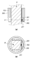
5 is a longitudinal sectional view and a plan sectional view of a busbar performance monitoring device according to an embodiment of the present invention.
이하, 도면을 참조하여 본 발명의 바람직한 실시예를 상세히 설명한다.Hereinafter, preferred embodiments of the present invention will be described in detail with reference to the drawings.
도 1 및 도 2는 본 발명의 일 실시예에 따른 부스바 성능감시장치의 설명을 위한 개념도이다.1 and 2 are conceptual diagrams for explaining a busbar performance monitoring device according to an embodiment of the present invention.
본 발명의 부스바 성능감시장치(10)는 부스바(Bus Bar)(B)를 감싸도록 설치된다. 부스바(B)는 예를 들면 22.9kV급의 고전압 부스바일 수 있다. 이하의 설명에서는 판상형 부스바(B)를 예로 들어 설명하지만, 본 발명은 원통형 부스바에도 적용 가능하다.The bus bar
본 발명의 부스바 성능감시장치(10)는 철심 코어(100)와 성능감시부(200)를 구비한다. 철심 코어(100) 및/또는 성능감시부(200)는 하우징 내에 수용될 수 있다. 하우징 수용 구조에 대해서는 도 5를 참조하여 후술한다.The busbar
본 발명의 부스바 성능감시장치(10)는 부스바(B)에 흐르는 전류로부터 전력을 공급받는다. 이를 위하여 본 발명의 부스바 성능감시장치(10)는 부스바(B)를 감싸도록 설치되는 철심 코어(100)를 구비한다. 철심 코어(100)에는 코일(210)이 권선되어 있어서, 부스바(B)를 통해 흐르는 교류 전류에 의해 코일(210)에 유도전류가 유기된다. The busbar
코일(210)을 통해 흐르는 유도전류는 성능감시부(200)에 공급된다. 성능감시부(200)는 도 3에 도시한 것처럼 코일(210)을 통해 유기되는 유도전압을 원하는 레벨의 전압으로 변환하기 위한 변압부(220)와, 변압부(220)에서 출력되는 교류 전압을 직류 전압으로 변환하는 정류부(230)와, 정류부(230)로부터의 직류 전압을 공급받아서 온도를 감지하는 온도 감지부(240)와 온도 감지부(240)로부터의 온도 신호를 광케이블(O)을 통해 외부 수신장치(R)로 전송하는 광전송부(250)를 구비한다. 부스바(B)에 흐르는 고압의 교류 전류에 의해 야기되는 강한 자기장의 영향으로부터 벗어나기 위하여 본 발명에서는 측정된 온도 신호를 광케이블(O)을 통해 외부 수신장치(R)로 전송한다. 외부 수신장치(R)는 광케이블(O)을 통해 수신한 온도 신호를 사용하여 부스바(B)의 성능을 감시한다. 성능감시부(200)에는 광케이블(O)의 연결을 위한 커넥터가 구비될 수 있다.The induced current flowing through the
도 4에 성능감시부(200)의 한가지 예가 도시되어 있다. 코일(210)로부터의 유도 전류는 저항(R9, R10, R11) 및 바리스터(D12, D13)로 구성되는 과전압 및 과전류 보호회로를 거쳐 전압 변환을 위한 트랜스포머(T1, T2)의 1차측에 인가되고, 트랜스포머(T1, T2)의 1차측 및 2차측의 권선비에 의해 결정되는 변환비에 따라 변환된 전압이 커넥터(J1, J3)를 통해 정류부(230)로 전달된다. 도 4에서 정류부(230)는 다이오드 D3, D4, D8, D9 및 커패시터 C1으로 구성되는 전파정류회로에서 전파 정류되어 직류전압 Vcc로서 온도감지부(240) 및 광전송부(250)의 각 소자에 공급된다. One example of the
온도감지센서(U1)에서 출력되는 측정 신호는 광다이오드부(251)를 구동하는 광다이오드 구동부(252)로 전달되고, 광다이오드(D2)에서 광신호로 변환되어 광케이블(O)을 통해 외부 수신장치(R)로 전송된다.The measurement signal output from the temperature sensor (U1) is transmitted to the
부스바(B)에는 예를 들면 22.9kV 정도의 고전압이 인가된다. 따라서, 고전압으로 인해 부스바에 센서를 직접 연결하는데는 어려운 점이 있다. 이를 감안하여 본 발명에서는 철심 코어(100)와 성능감시부(200)를 절연물질로 이루어진 하우징(300) 내에 실장하여 부스바(B)에 설치한다.A high voltage of, for example, about 22.9kV is applied to the busbar (B). Therefore, it is difficult to directly connect the sensor to the busbar due to the high voltage. In view of this, in the present invention, the
도 5에 하우징을 구비하는 부스바 성능감시장치(10)의 한가지 실시예가 도시되어 있다. 도 5의 (a)는 본 발명의 일 실시예에 따른 부스바 성능감시장치의 종단면도이고 (b)는 평단면도이다.One embodiment of a busbar
하우징(300)은 철심 코어(100)를 수용하는 공간과 성능감시부(200)를 수용하는 공간(302)을 구비하며, 내부에 철심 코어(100)와 성능감시부(200)를 수용한다. 바람직하게는, 철심 코어(100)를 수용하는 공간과 성능감시부(200)를 수용하는 공간이 통로(301)를 통해 연통된다. 철심 코어(100)에 감겨져 있는 코일(210)은 이 통로(301)를 통해 회로기판(260)으로 연결된다. 하우징(300)은 실리콘, 플라스틱 등의 절연물질로 구성된다. The
성능감시부(200)의 각 회로소자는 회로기판(260)에 실장된다. 온도센서(241)는 바람직하게는 부스바(B)를 향하도록 회로기판(260)에 실장되어 있다. 예를 들어, 회로기판의 상면이 부스바(B)를 향하도록 실장되는 경우에는 온도센서(241)는 회로기판(260)의 상면에 실장되고, 회로기판의 하면이 부스바(B)를 향하도록 실장되는 경우에는 온도센서(241)는 회로기판(260)의 하면에 실장된다. 실장부스바(B)의 온도를 보다 정확하게 측정하기 위하여 온도센서(241)가 설치된 곳의 하우징에 온도센서(241)가 부스바(B)를 향하여 노출되도록 개구부를 형성하는 것이 바람직하다. Each circuit element of the
일 실시예에서 하우징(300)은 제1 하우징과 제2 하우징을 구비할 수 있다. 제1 하우징과 제2 하우징은 힌지에 의해 개방상태 및 결합상태로 개폐되도록 구성할 수도 있고, 또는 별도의 결합수단에 의해 분리 및 결합되도록 구성할 수도 있다. 이 경우에 철심 코어(100)는 제1 하우징에 수용되는 부분과 제2 하우징에 수용되는 부분으로 구성된다. 회로기판(260)은 제1 하우징 또는 제2 하우징 중의 어느 하나에 실장된다. 회로기판(260)을 수용하기 위한 별도의 하우징을 더 마련할 수도 있다.In one embodiment, the
절연물질로 구성된 하우징(300) 내에 철심 코어(100)와 성능감시부(200)를 내장함으로써 부스바 성능감시장치(10)의 설치 및 유지보수가 간편해지고 안전해진다. 또한, 온도센서(241)가 하우징(300) 내에서 부스바(B)를 향하도록 회로기판(260)에 실장되어 있으므로, 외부 환경의 영향이 감소되고 온도 측정값이 보다 정확해진다.By embedding the
한편, 도 5에서는 하우징(300)의 철심 코어(100)가 내장되는 부분의 지름과 성능감시부(200)가 내장되는 부분의 지름이 다른 경우를 도시하고 있지만, 양 부분의 지름을 동일하게 구성할 수도 있다. 또한, 철심 코어(100)가 내장되는 부분을 성능감시부(200)가 내장되는 부분보다 아래에 위치하도록 구성할 수도 있다.On the other hand, Fig. 5 shows a case where the diameter of the part in which the
이상 본 발명을 몇가지 예를 들어 설명하였으나, 본 발명은 예시된 특정 구성에 한정되는 것은 아니다. 예를 들면 철심 코어 대신에 페라이트 코어를 사용할 수도 있다. 하우징의 형태도 원통형이 아닌 사각기둥형, 육각기둥형 등 다양한 형태로 구성할 수 있다.Although the present invention has been described by way of example, the present invention is not limited to the specific configuration illustrated. For example, a ferrite core may be used instead of the iron core core. The shape of the housing can also be configured in a variety of shapes, such as a square column shape and a hexagonal column shape instead of a cylindrical shape.
이상에서 실시예들에 설명된 특징, 구조, 효과 등은 본 발명의 하나의 실시예에 포함되며, 반드시 하나의 실시예에만 한정되는 것은 아니다. 나아가, 각 실시예에서 예시된 특징, 구조, 효과 등은 실시예들이 속하는 분야의 통상의 지식을 가지는 자에 의해 다른 실시예들에 대해서도 조합 또는 변형되어 실시 가능하다. 따라서 이러한 조합과 변형에 관계된 내용들은 본 발명의 범위에 포함되는 것으로 해석되어야 할 것이다.Features, structures, effects, and the like described in the above embodiments are included in one embodiment of the present invention, and are not necessarily limited to only one embodiment. Furthermore, the features, structures, effects, and the like illustrated in each embodiment may be combined or modified for other embodiments by a person having ordinary knowledge in the field to which the embodiments belong. Therefore, contents related to such combinations and modifications should be construed as being included in the scope of the present invention.
또한, 이상에서 실시예를 중심으로 설명하였으나 이는 단지 예시일 뿐 본 발명을 한정하는 것이 아니며, 본 발명이 속하는 분야의 통상의 지식을 가진 자라면 본 실시예의 본질적인 특성을 벗어나지 않는 범위에서 이상에 예시되지 않은 여러 가지의 변형과 응용이 가능함을 알 수 있을 것이다. 예를 들어, 실시예에 구체적으로 나타난 각 구성 요소는 변형하여 실시할 수 있는 것이다. 그리고 이러한 변형과 응용에 관계된 차이점들은 첨부된 청구 범위에서 규정하는 본 발명의 범위에 포함되는 것으로 해석되어야 할 것이다.In addition, although the embodiments have been described above, these are only examples and do not limit the present invention, and those of ordinary skill in the field to which the present invention pertains are illustrated above within the scope not departing from the essential characteristics of the present embodiment. It will be seen that various modifications and applications that are not available are possible. For example, each component specifically shown in the embodiment can be modified and implemented. And differences related to these modifications and applications should be construed as being included in the scope of the present invention defined in the appended claims.
10
부스바 성능감시장치,
100
철심 코어,
200
성능감시부,
210
코일,
220
변압부,
230
정류부,
240
온도 감지부,
241
온도센서,
250
광전송부,
260
회로기판10 Busbar performance monitoring device,
100 iron core core,
200 Performance monitoring unit,
210 coils,
220 transformer,
230 rectification part,
240 temperature sensing unit,
241 temperature sensor,
250 optical transmission unit,
260 circuit board
Claims (6)
상기 부스바의 온도를 측정하여 전송하는 성능감시부를 구비하며,
상기 성능감시부는,
상기 철심 코어에 감겨진 코일;
상기 코일을 통해 유기되는 유도 전압을 원하는 레벨의 전압으로 변환하는 변압부;
상기 변압부에서 출력되는 교류 전압을 직류 전압으로 변환하는 정류부;
온도센서를 포함하며 정류부로부터의 직류 전압을 공급받아서 온도를 감지하는 온도 감지부; 및
온도 감지부로부터의 온도 신호를 광케이블을 통해 외부 수신장치로 전송하는 광전송부를 포함하는,
부스바 성능감시장치.
An iron core configured to surround the busbar; And
It has a performance monitoring unit that measures and transmits the temperature of the bus bar,
The performance monitoring unit,
A coil wound around the iron core;
A transformer converting the induced voltage induced through the coil into a voltage of a desired level;
A rectifier converting the AC voltage output from the transformer into a DC voltage;
A temperature sensing unit that includes a temperature sensor and senses a temperature by receiving a DC voltage from the rectifying unit; And
Including an optical transmission unit for transmitting the temperature signal from the temperature sensing unit to an external receiving device through an optical cable,
Busbar performance monitoring device.
상기 철심 코어와 성능감시부를 수용하는 하우징을 더 구비하는, 부스바 성능감시장치.
The method of claim 1,
A busbar performance monitoring device further comprising a housing for accommodating the core core and the performance monitoring unit.
상기 하우징에는 철심 코어를 수용하는 공간과, 상기 성능감시부를 수용하는 공간이 형성되어 있으며,
상기 철심 코어를 수용하는 공간과 상기 성능감시부를 수용하는 공간은 통로를 통해 연통되며, 상기 통로를 통해 상기 코일이 상기 철심 코어에서 상기 변압부로 연결되는, 부스바 성능감시장치.
The method of claim 2,
A space for accommodating the core core and a space for accommodating the performance monitoring unit are formed in the housing,
The space accommodating the core core and the space accommodating the performance monitoring unit are communicated through a passage, and the coil is connected from the iron core to the transformer through the passage.
상기 온도센서는 부스바를 향하도록 회로기판에 실장되는, 부스바 성능감시장치.
The method of claim 2,
The temperature sensor is mounted on a circuit board so as to face the bus bar.
상기 하우징의 상기 온도센서가 설치된 곳에는 상기 온도센서가 부스바를 향하여 노출되도록 개구부가 형성되어 있는, 부스바 성능감시장치.
The method of claim 4,
Where the temperature sensor of the housing is installed, an opening is formed so that the temperature sensor is exposed toward the busbar.
상기 하우징은 제1 하우징과 제2 하우징을 구비하며,
상기 철심 코어는 제1 하우징에 수용되는 부분과 제2 하우징에 수용되는 부분으로 구성되며,
상기 제1 하우징과 제2 하우징은 결합수단에 의해 분리 및 결합되도록 구성되는, 부스바 성능감시장치.
The method according to any one of claims 2 to 5,
The housing has a first housing and a second housing,
The iron core core is composed of a portion received in the first housing and a portion received in the second housing,
The first housing and the second housing are configured to be separated and coupled by a coupling means, busbar performance monitoring device.
Priority Applications (1)
| Application Number | Priority Date | Filing Date | Title |
|---|---|---|---|
| KR1020190115214A KR20210033660A (en) | 2019-09-19 | 2019-09-19 | Apparatus for monitoring bus bar performance |
Applications Claiming Priority (1)
| Application Number | Priority Date | Filing Date | Title |
|---|---|---|---|
| KR1020190115214A KR20210033660A (en) | 2019-09-19 | 2019-09-19 | Apparatus for monitoring bus bar performance |
Publications (1)
| Publication Number | Publication Date |
|---|---|
| KR20210033660A true KR20210033660A (en) | 2021-03-29 |
Family
ID=75249982
Family Applications (1)
| Application Number | Title | Priority Date | Filing Date |
|---|---|---|---|
| KR1020190115214A KR20210033660A (en) | 2019-09-19 | 2019-09-19 | Apparatus for monitoring bus bar performance |
Country Status (1)
| Country | Link |
|---|---|
| KR (1) | KR20210033660A (en) |
Cited By (2)
| Publication number | Priority date | Publication date | Assignee | Title |
|---|---|---|---|---|
| CN114577363A (en) * | 2021-09-18 | 2022-06-03 | 常州亚盾测控技术有限公司 | Bus temperature rise on-line monitoring feedback system |
| KR102411422B1 (en) * | 2022-03-25 | 2022-06-22 | 주식회사 아이파워 | Powerless Busbar Performance Monitoring Device for Switchboard |
-
2019
- 2019-09-19 KR KR1020190115214A patent/KR20210033660A/en not_active Application Discontinuation
Cited By (3)
| Publication number | Priority date | Publication date | Assignee | Title |
|---|---|---|---|---|
| CN114577363A (en) * | 2021-09-18 | 2022-06-03 | 常州亚盾测控技术有限公司 | Bus temperature rise on-line monitoring feedback system |
| CN114577363B (en) * | 2021-09-18 | 2023-08-11 | 常州亚盾测控技术有限公司 | Bus temperature rise on-line monitoring feedback system |
| KR102411422B1 (en) * | 2022-03-25 | 2022-06-22 | 주식회사 아이파워 | Powerless Busbar Performance Monitoring Device for Switchboard |
Similar Documents
| Publication | Publication Date | Title |
|---|---|---|
| US7633262B2 (en) | Power supply for underground and pad mounted power distribution systems | |
| JP3071220B2 (en) | Self-powered power line sensor | |
| US4420752A (en) | Real-time parameter sensor-transmitter | |
| US4268818A (en) | Real-time parameter sensor-transmitter | |
| KR101604110B1 (en) | Busbar of switchgear integrated management system by using non contackt type integrated temperature and humidity sensor | |
| KR20210033660A (en) | Apparatus for monitoring bus bar performance | |
| US10014679B2 (en) | Electrical switching apparatus including alternating current electronic trip circuit with arc fault detection circuit and power supply | |
| KR101606704B1 (en) | Distributing Panel Having Power Line Checking Device and Protective Relay Operation Sound Warning Device | |
| KR102230392B1 (en) | Self cooling device | |
| US9698609B2 (en) | Testing device power induced by current transformer | |
| KR101386406B1 (en) | Distributing board having wireless temperature sensor module for detecting surface temperature on busbar | |
| WO2013166428A1 (en) | A current sensor having an integral voltage clamp | |
| CA3089157A1 (en) | Apparatus, system and method for temperature measurement for dry-type transformer | |
| KR101582828B1 (en) | Proximity Sound Warning Device Using Single-Loop Type Optical Communication By Measuring Temperature of Power Supply | |
| KR102411422B1 (en) | Powerless Busbar Performance Monitoring Device for Switchboard | |
| KR102212166B1 (en) | High output power supply easily installed in underground transmission line with improved waterproof/dustproof function | |
| KR100855743B1 (en) | A safety Apparatus for indicating running state of transformer | |
| CN208316315U (en) | A kind of device of self energizing | |
| KR101126291B1 (en) | Current and voltage sensor mounted to a pole transformer | |
| CN214589718U (en) | Wire outlet terminal and inflatable cabinet with same | |
| JP2002313450A (en) | Electricity measuring wire fitting and power converting method | |
| KR200293060Y1 (en) | A temperature measuring device for high power cable using electromagnetic induction | |
| US20230402832A1 (en) | Integrator for protective relay | |
| KR102469436B1 (en) | Temperature Measuring Device Using High Density Magnetic Field at the Bent Point of the Switchboard Busbar | |
| CN211265256U (en) | Safe, convenient and pollution-resistant voltage transformer |
Legal Events
| Date | Code | Title | Description |
|---|---|---|---|
| E601 | Decision to refuse application |