KR20210027368A - R&A bioreactor for in vitro transcription - Google Patents
R&A bioreactor for in vitro transcription Download PDFInfo
- Publication number
- KR20210027368A KR20210027368A KR1020217001173A KR20217001173A KR20210027368A KR 20210027368 A KR20210027368 A KR 20210027368A KR 1020217001173 A KR1020217001173 A KR 1020217001173A KR 20217001173 A KR20217001173 A KR 20217001173A KR 20210027368 A KR20210027368 A KR 20210027368A
- Authority
- KR
- South Korea
- Prior art keywords
- reaction vessel
- bioreactor
- rna
- dna
- magnetic particles
- Prior art date
Links
- 238000000338 in vitro Methods 0.000 title claims abstract description 94
- 238000013518 transcription Methods 0.000 title claims abstract description 86
- 230000035897 transcription Effects 0.000 title claims abstract description 86
- 238000006243 chemical reaction Methods 0.000 claims abstract description 404
- 238000000034 method Methods 0.000 claims abstract description 157
- 239000000203 mixture Substances 0.000 claims abstract description 71
- 238000004519 manufacturing process Methods 0.000 claims abstract description 42
- 238000009472 formulation Methods 0.000 claims abstract description 17
- 108020004414 DNA Proteins 0.000 claims description 262
- 239000006249 magnetic particle Substances 0.000 claims description 225
- 230000005291 magnetic effect Effects 0.000 claims description 163
- 239000012530 fluid Substances 0.000 claims description 76
- 238000002156 mixing Methods 0.000 claims description 66
- 230000008569 process Effects 0.000 claims description 45
- 238000004140 cleaning Methods 0.000 claims description 40
- 239000002699 waste material Substances 0.000 claims description 37
- 108091032973 (ribonucleotides)n+m Proteins 0.000 claims description 36
- 230000033001 locomotion Effects 0.000 claims description 34
- 238000010584 magnetic trap Methods 0.000 claims description 24
- 238000010438 heat treatment Methods 0.000 claims description 23
- 239000011324 bead Substances 0.000 claims description 22
- 239000000872 buffer Substances 0.000 claims description 21
- 239000002245 particle Substances 0.000 claims description 16
- 238000001816 cooling Methods 0.000 claims description 15
- 238000000151 deposition Methods 0.000 claims description 15
- 230000008021 deposition Effects 0.000 claims description 14
- 230000001954 sterilising effect Effects 0.000 claims description 12
- 102000004163 DNA-directed RNA polymerases Human genes 0.000 claims description 11
- 108090000626 DNA-directed RNA polymerases Proteins 0.000 claims description 11
- TWRXJAOTZQYOKJ-UHFFFAOYSA-L Magnesium chloride Chemical compound [Mg+2].[Cl-].[Cl-] TWRXJAOTZQYOKJ-UHFFFAOYSA-L 0.000 claims description 10
- 230000001419 dependent effect Effects 0.000 claims description 10
- -1 ribonucleoside triphosphates Chemical class 0.000 claims description 10
- 230000006820 DNA synthesis Effects 0.000 claims description 9
- 230000005298 paramagnetic effect Effects 0.000 claims description 9
- 235000011178 triphosphate Nutrition 0.000 claims description 8
- 239000001226 triphosphate Substances 0.000 claims description 8
- 150000003839 salts Chemical class 0.000 claims description 7
- RTAQQCXQSZGOHL-UHFFFAOYSA-N Titanium Chemical compound [Ti] RTAQQCXQSZGOHL-UHFFFAOYSA-N 0.000 claims description 6
- 239000013612 plasmid Substances 0.000 claims description 6
- 238000006116 polymerization reaction Methods 0.000 claims description 6
- 229910052719 titanium Inorganic materials 0.000 claims description 6
- 239000010936 titanium Substances 0.000 claims description 6
- 108010090804 Streptavidin Proteins 0.000 claims description 5
- UDMBCSSLTHHNCD-KQYNXXCUSA-N adenosine 5'-monophosphate Chemical compound C1=NC=2C(N)=NC=NC=2N1[C@@H]1O[C@H](COP(O)(O)=O)[C@@H](O)[C@H]1O UDMBCSSLTHHNCD-KQYNXXCUSA-N 0.000 claims description 5
- 239000003963 antioxidant agent Substances 0.000 claims description 5
- 210000000988 bone and bone Anatomy 0.000 claims description 5
- 238000001914 filtration Methods 0.000 claims description 5
- 229910001629 magnesium chloride Inorganic materials 0.000 claims description 5
- 239000011148 porous material Substances 0.000 claims description 5
- 239000003161 ribonuclease inhibitor Substances 0.000 claims description 5
- 230000033228 biological regulation Effects 0.000 claims description 4
- 238000007481 next generation sequencing Methods 0.000 claims description 4
- 108090000765 processed proteins & peptides Proteins 0.000 claims description 4
- FYYHWMGAXLPEAU-UHFFFAOYSA-N Magnesium Chemical compound [Mg] FYYHWMGAXLPEAU-UHFFFAOYSA-N 0.000 claims description 3
- 239000002202 Polyethylene glycol Substances 0.000 claims description 3
- 102000007327 Protamines Human genes 0.000 claims description 3
- 108010007568 Protamines Proteins 0.000 claims description 3
- 102000009609 Pyrophosphatases Human genes 0.000 claims description 3
- 108010009413 Pyrophosphatases Proteins 0.000 claims description 3
- 108091028664 Ribonucleotide Proteins 0.000 claims description 3
- 239000000654 additive Substances 0.000 claims description 3
- 230000000996 additive effect Effects 0.000 claims description 3
- 230000003078 antioxidant effect Effects 0.000 claims description 3
- 238000004108 freeze drying Methods 0.000 claims description 3
- 238000003306 harvesting Methods 0.000 claims description 3
- 229910052749 magnesium Inorganic materials 0.000 claims description 3
- 239000011777 magnesium Substances 0.000 claims description 3
- 230000035515 penetration Effects 0.000 claims description 3
- 229920000768 polyamine Polymers 0.000 claims description 3
- 229920001223 polyethylene glycol Polymers 0.000 claims description 3
- 229920000642 polymer Polymers 0.000 claims description 3
- 238000012545 processing Methods 0.000 claims description 3
- 229940048914 protamine Drugs 0.000 claims description 3
- 239000002342 ribonucleoside Substances 0.000 claims description 3
- 239000002336 ribonucleotide Substances 0.000 claims description 3
- 238000001694 spray drying Methods 0.000 claims description 3
- UNXRWKVEANCORM-UHFFFAOYSA-N triphosphoric acid Chemical compound OP(O)(=O)OP(O)(=O)OP(O)(O)=O UNXRWKVEANCORM-UHFFFAOYSA-N 0.000 claims description 3
- 102000053602 DNA Human genes 0.000 claims description 2
- 229910019142 PO4 Inorganic materials 0.000 claims description 2
- 101710141795 Ribonuclease inhibitor Proteins 0.000 claims description 2
- 229940122208 Ribonuclease inhibitor Drugs 0.000 claims description 2
- 102100037968 Ribonuclease inhibitor Human genes 0.000 claims description 2
- 238000005251 capillar electrophoresis Methods 0.000 claims description 2
- 230000006698 induction Effects 0.000 claims description 2
- 238000004949 mass spectrometry Methods 0.000 claims description 2
- NBIIXXVUZAFLBC-UHFFFAOYSA-K phosphate Chemical compound [O-]P([O-])([O-])=O NBIIXXVUZAFLBC-UHFFFAOYSA-K 0.000 claims description 2
- 239000010452 phosphate Substances 0.000 claims description 2
- 230000002040 relaxant effect Effects 0.000 claims description 2
- 125000002652 ribonucleotide group Chemical group 0.000 claims description 2
- 238000012546 transfer Methods 0.000 claims description 2
- 230000003252 repetitive effect Effects 0.000 abstract description 5
- 230000002194 synthesizing effect Effects 0.000 abstract 1
- 229920002477 rna polymer Polymers 0.000 description 226
- 239000007789 gas Substances 0.000 description 25
- 238000010586 diagram Methods 0.000 description 21
- 239000000047 product Substances 0.000 description 20
- 210000004027 cell Anatomy 0.000 description 19
- 238000003752 polymerase chain reaction Methods 0.000 description 18
- 102000004190 Enzymes Human genes 0.000 description 15
- 108090000790 Enzymes Proteins 0.000 description 15
- 238000000746 purification Methods 0.000 description 15
- 230000008901 benefit Effects 0.000 description 14
- 238000011049 filling Methods 0.000 description 13
- 230000001976 improved effect Effects 0.000 description 13
- 238000004378 air conditioning Methods 0.000 description 10
- 239000000463 material Substances 0.000 description 10
- 125000003729 nucleotide group Chemical group 0.000 description 10
- 238000009295 crossflow filtration Methods 0.000 description 9
- 239000003814 drug Substances 0.000 description 7
- 108090000623 proteins and genes Proteins 0.000 description 7
- 102000004169 proteins and genes Human genes 0.000 description 7
- 238000004128 high performance liquid chromatography Methods 0.000 description 6
- 230000000670 limiting effect Effects 0.000 description 6
- 239000002773 nucleotide Substances 0.000 description 6
- 239000004055 small Interfering RNA Substances 0.000 description 6
- 238000004659 sterilization and disinfection Methods 0.000 description 6
- 238000003756 stirring Methods 0.000 description 6
- 230000008961 swelling Effects 0.000 description 6
- 238000005842 biochemical reaction Methods 0.000 description 5
- 230000000593 degrading effect Effects 0.000 description 5
- 230000002255 enzymatic effect Effects 0.000 description 5
- 239000012634 fragment Substances 0.000 description 5
- 108020004999 messenger RNA Proteins 0.000 description 5
- 238000004007 reversed phase HPLC Methods 0.000 description 5
- 238000011144 upstream manufacturing Methods 0.000 description 5
- 108091033409 CRISPR Proteins 0.000 description 4
- 108091028075 Circular RNA Proteins 0.000 description 4
- 230000004913 activation Effects 0.000 description 4
- 238000013019 agitation Methods 0.000 description 4
- 230000015572 biosynthetic process Effects 0.000 description 4
- 230000005672 electromagnetic field Effects 0.000 description 4
- 239000011810 insulating material Substances 0.000 description 4
- 239000007788 liquid Substances 0.000 description 4
- 230000005415 magnetization Effects 0.000 description 4
- 102000039446 nucleic acids Human genes 0.000 description 4
- 108020004707 nucleic acids Proteins 0.000 description 4
- 150000007523 nucleic acids Chemical class 0.000 description 4
- 230000000737 periodic effect Effects 0.000 description 4
- 238000003908 quality control method Methods 0.000 description 4
- 239000000126 substance Substances 0.000 description 4
- 238000011282 treatment Methods 0.000 description 4
- 102000040650 (ribonucleotides)n+m Human genes 0.000 description 3
- UDMBCSSLTHHNCD-UHFFFAOYSA-N Coenzym Q(11) Natural products C1=NC=2C(N)=NC=NC=2N1C1OC(COP(O)(O)=O)C(O)C1O UDMBCSSLTHHNCD-UHFFFAOYSA-N 0.000 description 3
- HEMHJVSKTPXQMS-UHFFFAOYSA-M Sodium hydroxide Chemical compound [OH-].[Na+] HEMHJVSKTPXQMS-UHFFFAOYSA-M 0.000 description 3
- 229950006790 adenosine phosphate Drugs 0.000 description 3
- 238000011109 contamination Methods 0.000 description 3
- 235000011180 diphosphates Nutrition 0.000 description 3
- 230000006870 function Effects 0.000 description 3
- 239000011521 glass Substances 0.000 description 3
- 238000012544 monitoring process Methods 0.000 description 3
- 108091027963 non-coding RNA Proteins 0.000 description 3
- 102000042567 non-coding RNA Human genes 0.000 description 3
- 230000002829 reductive effect Effects 0.000 description 3
- 230000001105 regulatory effect Effects 0.000 description 3
- 238000007789 sealing Methods 0.000 description 3
- 239000000243 solution Substances 0.000 description 3
- 238000013022 venting Methods 0.000 description 3
- XLYOFNOQVPJJNP-UHFFFAOYSA-N water Substances O XLYOFNOQVPJJNP-UHFFFAOYSA-N 0.000 description 3
- JKMHFZQWWAIEOD-UHFFFAOYSA-N 2-[4-(2-hydroxyethyl)piperazin-1-yl]ethanesulfonic acid Chemical compound OCC[NH+]1CCN(CCS([O-])(=O)=O)CC1 JKMHFZQWWAIEOD-UHFFFAOYSA-N 0.000 description 2
- 108020005544 Antisense RNA Proteins 0.000 description 2
- 238000010354 CRISPR gene editing Methods 0.000 description 2
- KRKNYBCHXYNGOX-UHFFFAOYSA-K Citrate Chemical compound [O-]C(=O)CC(O)(CC([O-])=O)C([O-])=O KRKNYBCHXYNGOX-UHFFFAOYSA-K 0.000 description 2
- 230000004544 DNA amplification Effects 0.000 description 2
- LYCAIKOWRPUZTN-UHFFFAOYSA-N Ethylene glycol Chemical compound OCCO LYCAIKOWRPUZTN-UHFFFAOYSA-N 0.000 description 2
- 239000007995 HEPES buffer Substances 0.000 description 2
- 108090000604 Hydrolases Proteins 0.000 description 2
- 102000004157 Hydrolases Human genes 0.000 description 2
- 108700011259 MicroRNAs Proteins 0.000 description 2
- 108091007412 Piwi-interacting RNA Proteins 0.000 description 2
- 229920002684 Sepharose Polymers 0.000 description 2
- 102000039471 Small Nuclear RNA Human genes 0.000 description 2
- 108020003224 Small Nucleolar RNA Proteins 0.000 description 2
- 102000042773 Small Nucleolar RNA Human genes 0.000 description 2
- 108091027967 Small hairpin RNA Proteins 0.000 description 2
- 108020004459 Small interfering RNA Proteins 0.000 description 2
- 239000007983 Tris buffer Substances 0.000 description 2
- ISAKRJDGNUQOIC-UHFFFAOYSA-N Uracil Chemical compound O=C1C=CNC(=O)N1 ISAKRJDGNUQOIC-UHFFFAOYSA-N 0.000 description 2
- 230000003321 amplification Effects 0.000 description 2
- 239000005388 borosilicate glass Substances 0.000 description 2
- 239000007795 chemical reaction product Substances 0.000 description 2
- 230000003750 conditioning effect Effects 0.000 description 2
- 239000000470 constituent Substances 0.000 description 2
- 239000002826 coolant Substances 0.000 description 2
- 238000005260 corrosion Methods 0.000 description 2
- 230000007797 corrosion Effects 0.000 description 2
- OPTASPLRGRRNAP-UHFFFAOYSA-N cytosine Chemical compound NC=1C=CNC(=O)N=1 OPTASPLRGRRNAP-UHFFFAOYSA-N 0.000 description 2
- 238000011161 development Methods 0.000 description 2
- 230000029087 digestion Effects 0.000 description 2
- 238000009826 distribution Methods 0.000 description 2
- 238000002474 experimental method Methods 0.000 description 2
- 230000005484 gravity Effects 0.000 description 2
- UYTPUPDQBNUYGX-UHFFFAOYSA-N guanine Chemical compound O=C1NC(N)=NC2=C1N=CN2 UYTPUPDQBNUYGX-UHFFFAOYSA-N 0.000 description 2
- 230000003100 immobilizing effect Effects 0.000 description 2
- 230000003308 immunostimulating effect Effects 0.000 description 2
- 230000001939 inductive effect Effects 0.000 description 2
- 230000010354 integration Effects 0.000 description 2
- 230000005389 magnetism Effects 0.000 description 2
- 238000005259 measurement Methods 0.000 description 2
- 239000002679 microRNA Substances 0.000 description 2
- 238000003199 nucleic acid amplification method Methods 0.000 description 2
- 229920002530 polyetherether ketone Polymers 0.000 description 2
- 238000001556 precipitation Methods 0.000 description 2
- 230000002441 reversible effect Effects 0.000 description 2
- 108091029842 small nuclear ribonucleic acid Proteins 0.000 description 2
- 239000011343 solid material Substances 0.000 description 2
- ATHGHQPFGPMSJY-UHFFFAOYSA-N spermidine Chemical compound NCCCCNCCCN ATHGHQPFGPMSJY-UHFFFAOYSA-N 0.000 description 2
- 238000011146 sterile filtration Methods 0.000 description 2
- 230000008093 supporting effect Effects 0.000 description 2
- 230000001225 therapeutic effect Effects 0.000 description 2
- 238000013060 ultrafiltration and diafiltration Methods 0.000 description 2
- 238000005406 washing Methods 0.000 description 2
- UVBYMVOUBXYSFV-XUTVFYLZSA-N 1-methylpseudouridine Chemical compound O=C1NC(=O)N(C)C=C1[C@H]1[C@H](O)[C@H](O)[C@@H](CO)O1 UVBYMVOUBXYSFV-XUTVFYLZSA-N 0.000 description 1
- ZXIATBNUWJBBGT-JXOAFFINSA-N 5-methoxyuridine Chemical compound O=C1NC(=O)C(OC)=CN1[C@H]1[C@H](O)[C@H](O)[C@@H](CO)O1 ZXIATBNUWJBBGT-JXOAFFINSA-N 0.000 description 1
- LRSASMSXMSNRBT-UHFFFAOYSA-N 5-methylcytosine Chemical compound CC1=CNC(=O)N=C1N LRSASMSXMSNRBT-UHFFFAOYSA-N 0.000 description 1
- GFFGJBXGBJISGV-UHFFFAOYSA-N Adenine Chemical compound NC1=NC=NC2=C1N=CN2 GFFGJBXGBJISGV-UHFFFAOYSA-N 0.000 description 1
- 229930024421 Adenine Natural products 0.000 description 1
- 229920000936 Agarose Polymers 0.000 description 1
- 108091023037 Aptamer Proteins 0.000 description 1
- 101150077194 CAP1 gene Proteins 0.000 description 1
- 108090000994 Catalytic RNA Proteins 0.000 description 1
- 102000053642 Catalytic RNA Human genes 0.000 description 1
- 229910000976 Electrical steel Inorganic materials 0.000 description 1
- 108020005004 Guide RNA Proteins 0.000 description 1
- 206010028980 Neoplasm Diseases 0.000 description 1
- 101100438378 Neurospora crassa (strain ATCC 24698 / 74-OR23-1A / CBS 708.71 / DSM 1257 / FGSC 987) fac-1 gene Proteins 0.000 description 1
- 108091028043 Nucleic acid sequence Proteins 0.000 description 1
- 108091034117 Oligonucleotide Proteins 0.000 description 1
- 239000004698 Polyethylene Substances 0.000 description 1
- 229930185560 Pseudouridine Natural products 0.000 description 1
- PTJWIQPHWPFNBW-UHFFFAOYSA-N Pseudouridine C Natural products OC1C(O)C(CO)OC1C1=CNC(=O)NC1=O PTJWIQPHWPFNBW-UHFFFAOYSA-N 0.000 description 1
- 230000006819 RNA synthesis Effects 0.000 description 1
- 229940123752 RNA synthesis inhibitor Drugs 0.000 description 1
- 108091030084 RNA-OUT Proteins 0.000 description 1
- 238000011529 RT qPCR Methods 0.000 description 1
- 102000006382 Ribonucleases Human genes 0.000 description 1
- 108010083644 Ribonucleases Proteins 0.000 description 1
- 238000012300 Sequence Analysis Methods 0.000 description 1
- 238000003723 Smelting Methods 0.000 description 1
- 108091046869 Telomeric non-coding RNA Proteins 0.000 description 1
- 108020004566 Transfer RNA Proteins 0.000 description 1
- 108091034135 Vault RNA Proteins 0.000 description 1
- 108020000999 Viral RNA Proteins 0.000 description 1
- FHHZHGZBHYYWTG-INFSMZHSSA-N [(2r,3s,4r,5r)-5-(2-amino-7-methyl-6-oxo-3h-purin-9-ium-9-yl)-3,4-dihydroxyoxolan-2-yl]methyl [[[(2r,3s,4r,5r)-5-(2-amino-6-oxo-3h-purin-9-yl)-3,4-dihydroxyoxolan-2-yl]methoxy-hydroxyphosphoryl]oxy-hydroxyphosphoryl] phosphate Chemical compound N1C(N)=NC(=O)C2=C1[N+]([C@H]1[C@@H]([C@H](O)[C@@H](COP([O-])(=O)OP(O)(=O)OP(O)(=O)OC[C@@H]3[C@H]([C@@H](O)[C@@H](O3)N3C4=C(C(N=C(N)N4)=O)N=C3)O)O1)O)=CN2C FHHZHGZBHYYWTG-INFSMZHSSA-N 0.000 description 1
- JLCPHMBAVCMARE-UHFFFAOYSA-N [3-[[3-[[3-[[3-[[3-[[3-[[3-[[3-[[3-[[3-[[3-[[5-(2-amino-6-oxo-1H-purin-9-yl)-3-[[3-[[3-[[3-[[3-[[3-[[5-(2-amino-6-oxo-1H-purin-9-yl)-3-[[5-(2-amino-6-oxo-1H-purin-9-yl)-3-hydroxyoxolan-2-yl]methoxy-hydroxyphosphoryl]oxyoxolan-2-yl]methoxy-hydroxyphosphoryl]oxy-5-(5-methyl-2,4-dioxopyrimidin-1-yl)oxolan-2-yl]methoxy-hydroxyphosphoryl]oxy-5-(6-aminopurin-9-yl)oxolan-2-yl]methoxy-hydroxyphosphoryl]oxy-5-(6-aminopurin-9-yl)oxolan-2-yl]methoxy-hydroxyphosphoryl]oxy-5-(6-aminopurin-9-yl)oxolan-2-yl]methoxy-hydroxyphosphoryl]oxy-5-(6-aminopurin-9-yl)oxolan-2-yl]methoxy-hydroxyphosphoryl]oxyoxolan-2-yl]methoxy-hydroxyphosphoryl]oxy-5-(5-methyl-2,4-dioxopyrimidin-1-yl)oxolan-2-yl]methoxy-hydroxyphosphoryl]oxy-5-(4-amino-2-oxopyrimidin-1-yl)oxolan-2-yl]methoxy-hydroxyphosphoryl]oxy-5-(5-methyl-2,4-dioxopyrimidin-1-yl)oxolan-2-yl]methoxy-hydroxyphosphoryl]oxy-5-(5-methyl-2,4-dioxopyrimidin-1-yl)oxolan-2-yl]methoxy-hydroxyphosphoryl]oxy-5-(6-aminopurin-9-yl)oxolan-2-yl]methoxy-hydroxyphosphoryl]oxy-5-(6-aminopurin-9-yl)oxolan-2-yl]methoxy-hydroxyphosphoryl]oxy-5-(4-amino-2-oxopyrimidin-1-yl)oxolan-2-yl]methoxy-hydroxyphosphoryl]oxy-5-(4-amino-2-oxopyrimidin-1-yl)oxolan-2-yl]methoxy-hydroxyphosphoryl]oxy-5-(4-amino-2-oxopyrimidin-1-yl)oxolan-2-yl]methoxy-hydroxyphosphoryl]oxy-5-(6-aminopurin-9-yl)oxolan-2-yl]methoxy-hydroxyphosphoryl]oxy-5-(4-amino-2-oxopyrimidin-1-yl)oxolan-2-yl]methyl [5-(6-aminopurin-9-yl)-2-(hydroxymethyl)oxolan-3-yl] hydrogen phosphate Polymers Cc1cn(C2CC(OP(O)(=O)OCC3OC(CC3OP(O)(=O)OCC3OC(CC3O)n3cnc4c3nc(N)[nH]c4=O)n3cnc4c3nc(N)[nH]c4=O)C(COP(O)(=O)OC3CC(OC3COP(O)(=O)OC3CC(OC3COP(O)(=O)OC3CC(OC3COP(O)(=O)OC3CC(OC3COP(O)(=O)OC3CC(OC3COP(O)(=O)OC3CC(OC3COP(O)(=O)OC3CC(OC3COP(O)(=O)OC3CC(OC3COP(O)(=O)OC3CC(OC3COP(O)(=O)OC3CC(OC3COP(O)(=O)OC3CC(OC3COP(O)(=O)OC3CC(OC3COP(O)(=O)OC3CC(OC3COP(O)(=O)OC3CC(OC3COP(O)(=O)OC3CC(OC3COP(O)(=O)OC3CC(OC3COP(O)(=O)OC3CC(OC3CO)n3cnc4c(N)ncnc34)n3ccc(N)nc3=O)n3cnc4c(N)ncnc34)n3ccc(N)nc3=O)n3ccc(N)nc3=O)n3ccc(N)nc3=O)n3cnc4c(N)ncnc34)n3cnc4c(N)ncnc34)n3cc(C)c(=O)[nH]c3=O)n3cc(C)c(=O)[nH]c3=O)n3ccc(N)nc3=O)n3cc(C)c(=O)[nH]c3=O)n3cnc4c3nc(N)[nH]c4=O)n3cnc4c(N)ncnc34)n3cnc4c(N)ncnc34)n3cnc4c(N)ncnc34)n3cnc4c(N)ncnc34)O2)c(=O)[nH]c1=O JLCPHMBAVCMARE-UHFFFAOYSA-N 0.000 description 1
- 230000001133 acceleration Effects 0.000 description 1
- 239000002253 acid Substances 0.000 description 1
- 230000009471 action Effects 0.000 description 1
- 239000008186 active pharmaceutical agent Substances 0.000 description 1
- 229960000643 adenine Drugs 0.000 description 1
- 238000001261 affinity purification Methods 0.000 description 1
- 229910045601 alloy Inorganic materials 0.000 description 1
- 239000000956 alloy Substances 0.000 description 1
- 238000004458 analytical method Methods 0.000 description 1
- 239000000427 antigen Substances 0.000 description 1
- 108091007433 antigens Proteins 0.000 description 1
- 102000036639 antigens Human genes 0.000 description 1
- 229910000963 austenitic stainless steel Inorganic materials 0.000 description 1
- 238000010923 batch production Methods 0.000 description 1
- WGDUUQDYDIIBKT-UHFFFAOYSA-N beta-Pseudouridine Natural products OC1OC(CN2C=CC(=O)NC2=O)C(O)C1O WGDUUQDYDIIBKT-UHFFFAOYSA-N 0.000 description 1
- 239000007853 buffer solution Substances 0.000 description 1
- 201000011510 cancer Diseases 0.000 description 1
- 210000004671 cell-free system Anatomy 0.000 description 1
- 239000000919 ceramic Substances 0.000 description 1
- 230000008859 change Effects 0.000 description 1
- 239000003153 chemical reaction reagent Substances 0.000 description 1
- 150000001860 citric acid derivatives Chemical class 0.000 description 1
- 238000005345 coagulation Methods 0.000 description 1
- 230000015271 coagulation Effects 0.000 description 1
- 239000002299 complementary DNA Substances 0.000 description 1
- 239000003184 complementary RNA Substances 0.000 description 1
- 150000001875 compounds Chemical class 0.000 description 1
- 230000001143 conditioned effect Effects 0.000 description 1
- 239000004020 conductor Substances 0.000 description 1
- 230000001276 controlling effect Effects 0.000 description 1
- 229940104302 cytosine Drugs 0.000 description 1
- 230000007547 defect Effects 0.000 description 1
- 238000011033 desalting Methods 0.000 description 1
- 238000013461 design Methods 0.000 description 1
- 238000011026 diafiltration Methods 0.000 description 1
- 238000000502 dialysis Methods 0.000 description 1
- XPPKVPWEQAFLFU-UHFFFAOYSA-J diphosphate(4-) Chemical compound [O-]P([O-])(=O)OP([O-])([O-])=O XPPKVPWEQAFLFU-UHFFFAOYSA-J 0.000 description 1
- MYRTYDVEIRVNKP-UHFFFAOYSA-N divinylbenzene Substances C=CC1=CC=CC=C1C=C MYRTYDVEIRVNKP-UHFFFAOYSA-N 0.000 description 1
- 229940079593 drug Drugs 0.000 description 1
- 229940126534 drug product Drugs 0.000 description 1
- 229940088679 drug related substance Drugs 0.000 description 1
- 230000000694 effects Effects 0.000 description 1
- 238000010292 electrical insulation Methods 0.000 description 1
- 230000006862 enzymatic digestion Effects 0.000 description 1
- 238000006911 enzymatic reaction Methods 0.000 description 1
- 238000001976 enzyme digestion Methods 0.000 description 1
- 238000004880 explosion Methods 0.000 description 1
- 230000005294 ferromagnetic effect Effects 0.000 description 1
- 239000003302 ferromagnetic material Substances 0.000 description 1
- 239000012467 final product Substances 0.000 description 1
- 238000007667 floating Methods 0.000 description 1
- 238000001415 gene therapy Methods 0.000 description 1
- 238000010362 genome editing Methods 0.000 description 1
- 239000003102 growth factor Substances 0.000 description 1
- 229910000856 hastalloy Inorganic materials 0.000 description 1
- 239000008240 homogeneous mixture Substances 0.000 description 1
- WGCNASOHLSPBMP-UHFFFAOYSA-N hydroxyacetaldehyde Natural products OCC=O WGCNASOHLSPBMP-UHFFFAOYSA-N 0.000 description 1
- 238000009169 immunotherapy Methods 0.000 description 1
- 239000012774 insulation material Substances 0.000 description 1
- 230000003993 interaction Effects 0.000 description 1
- 150000002632 lipids Chemical class 0.000 description 1
- 238000010907 mechanical stirring Methods 0.000 description 1
- 239000012528 membrane Substances 0.000 description 1
- 108091070501 miRNA Proteins 0.000 description 1
- 230000000813 microbial effect Effects 0.000 description 1
- 230000000116 mitigating effect Effects 0.000 description 1
- 230000004048 modification Effects 0.000 description 1
- 238000012986 modification Methods 0.000 description 1
- 238000000465 moulding Methods 0.000 description 1
- 239000002105 nanoparticle Substances 0.000 description 1
- 239000002907 paramagnetic material Substances 0.000 description 1
- 230000036961 partial effect Effects 0.000 description 1
- 238000005192 partition Methods 0.000 description 1
- 230000002093 peripheral effect Effects 0.000 description 1
- 239000000825 pharmaceutical preparation Substances 0.000 description 1
- 239000006187 pill Substances 0.000 description 1
- 230000008488 polyadenylation Effects 0.000 description 1
- 229920006260 polyaryletherketone Polymers 0.000 description 1
- 229920000573 polyethylene Polymers 0.000 description 1
- 229920002223 polystyrene Polymers 0.000 description 1
- 238000002360 preparation method Methods 0.000 description 1
- PTJWIQPHWPFNBW-GBNDHIKLSA-N pseudouridine Chemical compound O[C@@H]1[C@H](O)[C@@H](CO)O[C@H]1C1=CNC(=O)NC1=O PTJWIQPHWPFNBW-GBNDHIKLSA-N 0.000 description 1
- 230000005180 public health Effects 0.000 description 1
- 239000012429 reaction media Substances 0.000 description 1
- 108091008146 restriction endonucleases Proteins 0.000 description 1
- 230000000717 retained effect Effects 0.000 description 1
- 230000001177 retroviral effect Effects 0.000 description 1
- 238000010839 reverse transcription Methods 0.000 description 1
- 108091092562 ribozyme Proteins 0.000 description 1
- 239000000523 sample Substances 0.000 description 1
- 238000000926 separation method Methods 0.000 description 1
- 229910052709 silver Inorganic materials 0.000 description 1
- 239000004332 silver Substances 0.000 description 1
- 229940063673 spermidine Drugs 0.000 description 1
- 239000007921 spray Substances 0.000 description 1
- 239000007858 starting material Substances 0.000 description 1
- 230000003746 surface roughness Effects 0.000 description 1
- 230000002195 synergetic effect Effects 0.000 description 1
- 229920003002 synthetic resin Polymers 0.000 description 1
- 239000000057 synthetic resin Substances 0.000 description 1
- 230000002123 temporal effect Effects 0.000 description 1
- 229920001169 thermoplastic Polymers 0.000 description 1
- 239000004416 thermosoftening plastic Substances 0.000 description 1
- 238000006276 transfer reaction Methods 0.000 description 1
- 230000001960 triggered effect Effects 0.000 description 1
- LENZDBCJOHFCAS-UHFFFAOYSA-N tris Chemical compound OCC(N)(CO)CO LENZDBCJOHFCAS-UHFFFAOYSA-N 0.000 description 1
- 238000000108 ultra-filtration Methods 0.000 description 1
- 229940035893 uracil Drugs 0.000 description 1
- 238000002255 vaccination Methods 0.000 description 1
- 229960005486 vaccine Drugs 0.000 description 1
- 239000011534 wash buffer Substances 0.000 description 1
- 239000002912 waste gas Substances 0.000 description 1
Images


Classifications
-
- C—CHEMISTRY; METALLURGY
- C12—BIOCHEMISTRY; BEER; SPIRITS; WINE; VINEGAR; MICROBIOLOGY; ENZYMOLOGY; MUTATION OR GENETIC ENGINEERING
- C12M—APPARATUS FOR ENZYMOLOGY OR MICROBIOLOGY; APPARATUS FOR CULTURING MICROORGANISMS FOR PRODUCING BIOMASS, FOR GROWING CELLS OR FOR OBTAINING FERMENTATION OR METABOLIC PRODUCTS, i.e. BIOREACTORS OR FERMENTERS
- C12M21/00—Bioreactors or fermenters specially adapted for specific uses
- C12M21/18—Apparatus specially designed for the use of free, immobilized or carrier-bound enzymes
-
- C—CHEMISTRY; METALLURGY
- C12—BIOCHEMISTRY; BEER; SPIRITS; WINE; VINEGAR; MICROBIOLOGY; ENZYMOLOGY; MUTATION OR GENETIC ENGINEERING
- C12Q—MEASURING OR TESTING PROCESSES INVOLVING ENZYMES, NUCLEIC ACIDS OR MICROORGANISMS; COMPOSITIONS OR TEST PAPERS THEREFOR; PROCESSES OF PREPARING SUCH COMPOSITIONS; CONDITION-RESPONSIVE CONTROL IN MICROBIOLOGICAL OR ENZYMOLOGICAL PROCESSES
- C12Q1/00—Measuring or testing processes involving enzymes, nucleic acids or microorganisms; Compositions therefor; Processes of preparing such compositions
- C12Q1/68—Measuring or testing processes involving enzymes, nucleic acids or microorganisms; Compositions therefor; Processes of preparing such compositions involving nucleic acids
- C12Q1/6844—Nucleic acid amplification reactions
- C12Q1/6865—Promoter-based amplification, e.g. nucleic acid sequence amplification [NASBA], self-sustained sequence replication [3SR] or transcription-based amplification system [TAS]
-
- B01F13/0818—
-
- B01F15/00896—
-
- B—PERFORMING OPERATIONS; TRANSPORTING
- B01—PHYSICAL OR CHEMICAL PROCESSES OR APPARATUS IN GENERAL
- B01F—MIXING, e.g. DISSOLVING, EMULSIFYING OR DISPERSING
- B01F33/00—Other mixers; Mixing plants; Combinations of mixers
- B01F33/45—Magnetic mixers; Mixers with magnetically driven stirrers
- B01F33/451—Magnetic mixers; Mixers with magnetically driven stirrers wherein the mixture is directly exposed to an electromagnetic field without use of a stirrer, e.g. for material comprising ferromagnetic particles or for molten metal
-
- B—PERFORMING OPERATIONS; TRANSPORTING
- B01—PHYSICAL OR CHEMICAL PROCESSES OR APPARATUS IN GENERAL
- B01F—MIXING, e.g. DISSOLVING, EMULSIFYING OR DISPERSING
- B01F33/00—Other mixers; Mixing plants; Combinations of mixers
- B01F33/45—Magnetic mixers; Mixers with magnetically driven stirrers
- B01F33/452—Magnetic mixers; Mixers with magnetically driven stirrers using independent floating stirring elements
-
- B—PERFORMING OPERATIONS; TRANSPORTING
- B01—PHYSICAL OR CHEMICAL PROCESSES OR APPARATUS IN GENERAL
- B01F—MIXING, e.g. DISSOLVING, EMULSIFYING OR DISPERSING
- B01F35/00—Accessories for mixers; Auxiliary operations or auxiliary devices; Parts or details of general application
- B01F35/50—Mixing receptacles
- B01F35/53—Mixing receptacles characterised by the configuration of the interior, e.g. baffles for facilitating the mixing of components
- B01F35/531—Mixing receptacles characterised by the configuration of the interior, e.g. baffles for facilitating the mixing of components with baffles, plates or bars on the wall or the bottom
- B01F35/5312—Mixing receptacles characterised by the configuration of the interior, e.g. baffles for facilitating the mixing of components with baffles, plates or bars on the wall or the bottom with vertical baffles mounted on the walls
-
- B—PERFORMING OPERATIONS; TRANSPORTING
- B01—PHYSICAL OR CHEMICAL PROCESSES OR APPARATUS IN GENERAL
- B01F—MIXING, e.g. DISSOLVING, EMULSIFYING OR DISPERSING
- B01F35/00—Accessories for mixers; Auxiliary operations or auxiliary devices; Parts or details of general application
- B01F35/90—Heating or cooling systems
- B01F35/92—Heating or cooling systems for heating the outside of the receptacle, e.g. heated jackets or burners
-
- C—CHEMISTRY; METALLURGY
- C12—BIOCHEMISTRY; BEER; SPIRITS; WINE; VINEGAR; MICROBIOLOGY; ENZYMOLOGY; MUTATION OR GENETIC ENGINEERING
- C12M—APPARATUS FOR ENZYMOLOGY OR MICROBIOLOGY; APPARATUS FOR CULTURING MICROORGANISMS FOR PRODUCING BIOMASS, FOR GROWING CELLS OR FOR OBTAINING FERMENTATION OR METABOLIC PRODUCTS, i.e. BIOREACTORS OR FERMENTERS
- C12M27/00—Means for mixing, agitating or circulating fluids in the vessel
- C12M27/02—Stirrer or mobile mixing elements
-
- C—CHEMISTRY; METALLURGY
- C12—BIOCHEMISTRY; BEER; SPIRITS; WINE; VINEGAR; MICROBIOLOGY; ENZYMOLOGY; MUTATION OR GENETIC ENGINEERING
- C12M—APPARATUS FOR ENZYMOLOGY OR MICROBIOLOGY; APPARATUS FOR CULTURING MICROORGANISMS FOR PRODUCING BIOMASS, FOR GROWING CELLS OR FOR OBTAINING FERMENTATION OR METABOLIC PRODUCTS, i.e. BIOREACTORS OR FERMENTERS
- C12M41/00—Means for regulation, monitoring, measurement or control, e.g. flow regulation
- C12M41/48—Automatic or computerized control
-
- C—CHEMISTRY; METALLURGY
- C12—BIOCHEMISTRY; BEER; SPIRITS; WINE; VINEGAR; MICROBIOLOGY; ENZYMOLOGY; MUTATION OR GENETIC ENGINEERING
- C12N—MICROORGANISMS OR ENZYMES; COMPOSITIONS THEREOF; PROPAGATING, PRESERVING, OR MAINTAINING MICROORGANISMS; MUTATION OR GENETIC ENGINEERING; CULTURE MEDIA
- C12N15/00—Mutation or genetic engineering; DNA or RNA concerning genetic engineering, vectors, e.g. plasmids, or their isolation, preparation or purification; Use of hosts therefor
- C12N15/09—Recombinant DNA-technology
- C12N15/10—Processes for the isolation, preparation or purification of DNA or RNA
- C12N15/1003—Extracting or separating nucleic acids from biological samples, e.g. pure separation or isolation methods; Conditions, buffers or apparatuses therefor
- C12N15/1006—Extracting or separating nucleic acids from biological samples, e.g. pure separation or isolation methods; Conditions, buffers or apparatuses therefor by means of a solid support carrier, e.g. particles, polymers
- C12N15/1013—Extracting or separating nucleic acids from biological samples, e.g. pure separation or isolation methods; Conditions, buffers or apparatuses therefor by means of a solid support carrier, e.g. particles, polymers by using magnetic beads
-
- C—CHEMISTRY; METALLURGY
- C12—BIOCHEMISTRY; BEER; SPIRITS; WINE; VINEGAR; MICROBIOLOGY; ENZYMOLOGY; MUTATION OR GENETIC ENGINEERING
- C12P—FERMENTATION OR ENZYME-USING PROCESSES TO SYNTHESISE A DESIRED CHEMICAL COMPOUND OR COMPOSITION OR TO SEPARATE OPTICAL ISOMERS FROM A RACEMIC MIXTURE
- C12P19/00—Preparation of compounds containing saccharide radicals
- C12P19/26—Preparation of nitrogen-containing carbohydrates
- C12P19/28—N-glycosides
- C12P19/30—Nucleotides
- C12P19/34—Polynucleotides, e.g. nucleic acids, oligoribonucleotides
-
- C—CHEMISTRY; METALLURGY
- C12—BIOCHEMISTRY; BEER; SPIRITS; WINE; VINEGAR; MICROBIOLOGY; ENZYMOLOGY; MUTATION OR GENETIC ENGINEERING
- C12Q—MEASURING OR TESTING PROCESSES INVOLVING ENZYMES, NUCLEIC ACIDS OR MICROORGANISMS; COMPOSITIONS OR TEST PAPERS THEREFOR; PROCESSES OF PREPARING SUCH COMPOSITIONS; CONDITION-RESPONSIVE CONTROL IN MICROBIOLOGICAL OR ENZYMOLOGICAL PROCESSES
- C12Q1/00—Measuring or testing processes involving enzymes, nucleic acids or microorganisms; Compositions therefor; Processes of preparing such compositions
- C12Q1/68—Measuring or testing processes involving enzymes, nucleic acids or microorganisms; Compositions therefor; Processes of preparing such compositions involving nucleic acids
- C12Q1/6876—Nucleic acid products used in the analysis of nucleic acids, e.g. primers or probes
- C12Q1/6888—Nucleic acid products used in the analysis of nucleic acids, e.g. primers or probes for detection or identification of organisms
- C12Q1/6895—Nucleic acid products used in the analysis of nucleic acids, e.g. primers or probes for detection or identification of organisms for plants, fungi or algae
-
- B—PERFORMING OPERATIONS; TRANSPORTING
- B01—PHYSICAL OR CHEMICAL PROCESSES OR APPARATUS IN GENERAL
- B01F—MIXING, e.g. DISSOLVING, EMULSIFYING OR DISPERSING
- B01F35/00—Accessories for mixers; Auxiliary operations or auxiliary devices; Parts or details of general application
- B01F35/90—Heating or cooling systems
- B01F2035/98—Cooling
-
- B—PERFORMING OPERATIONS; TRANSPORTING
- B01—PHYSICAL OR CHEMICAL PROCESSES OR APPARATUS IN GENERAL
- B01F—MIXING, e.g. DISSOLVING, EMULSIFYING OR DISPERSING
- B01F35/00—Accessories for mixers; Auxiliary operations or auxiliary devices; Parts or details of general application
- B01F35/90—Heating or cooling systems
- B01F2035/99—Heating
-
- B—PERFORMING OPERATIONS; TRANSPORTING
- B01—PHYSICAL OR CHEMICAL PROCESSES OR APPARATUS IN GENERAL
- B01F—MIXING, e.g. DISSOLVING, EMULSIFYING OR DISPERSING
- B01F2101/00—Mixing characterised by the nature of the mixed materials or by the application field
- B01F2101/22—Mixing of ingredients for pharmaceutical or medical compositions
-
- C—CHEMISTRY; METALLURGY
- C12—BIOCHEMISTRY; BEER; SPIRITS; WINE; VINEGAR; MICROBIOLOGY; ENZYMOLOGY; MUTATION OR GENETIC ENGINEERING
- C12Q—MEASURING OR TESTING PROCESSES INVOLVING ENZYMES, NUCLEIC ACIDS OR MICROORGANISMS; COMPOSITIONS OR TEST PAPERS THEREFOR; PROCESSES OF PREPARING SUCH COMPOSITIONS; CONDITION-RESPONSIVE CONTROL IN MICROBIOLOGICAL OR ENZYMOLOGICAL PROCESSES
- C12Q2521/00—Reaction characterised by the enzymatic activity
- C12Q2521/10—Nucleotidyl transfering
- C12Q2521/119—RNA polymerase
-
- C—CHEMISTRY; METALLURGY
- C12—BIOCHEMISTRY; BEER; SPIRITS; WINE; VINEGAR; MICROBIOLOGY; ENZYMOLOGY; MUTATION OR GENETIC ENGINEERING
- C12Q—MEASURING OR TESTING PROCESSES INVOLVING ENZYMES, NUCLEIC ACIDS OR MICROORGANISMS; COMPOSITIONS OR TEST PAPERS THEREFOR; PROCESSES OF PREPARING SUCH COMPOSITIONS; CONDITION-RESPONSIVE CONTROL IN MICROBIOLOGICAL OR ENZYMOLOGICAL PROCESSES
- C12Q2563/00—Nucleic acid detection characterized by the use of physical, structural and functional properties
- C12Q2563/143—Magnetism, e.g. magnetic label
Landscapes
- Chemical & Material Sciences (AREA)
- Life Sciences & Earth Sciences (AREA)
- Engineering & Computer Science (AREA)
- Health & Medical Sciences (AREA)
- Organic Chemistry (AREA)
- Zoology (AREA)
- Wood Science & Technology (AREA)
- Genetics & Genomics (AREA)
- Bioinformatics & Cheminformatics (AREA)
- Biotechnology (AREA)
- Biomedical Technology (AREA)
- General Engineering & Computer Science (AREA)
- Chemical Kinetics & Catalysis (AREA)
- Microbiology (AREA)
- Analytical Chemistry (AREA)
- Biochemistry (AREA)
- General Health & Medical Sciences (AREA)
- Molecular Biology (AREA)
- Biophysics (AREA)
- Physics & Mathematics (AREA)
- Proteomics, Peptides & Aminoacids (AREA)
- Crystallography & Structural Chemistry (AREA)
- Plant Pathology (AREA)
- Sustainable Development (AREA)
- Immunology (AREA)
- General Chemical & Material Sciences (AREA)
- Computer Hardware Design (AREA)
- Botany (AREA)
- Mycology (AREA)
- Apparatus Associated With Microorganisms And Enzymes (AREA)
- Preparation Of Compounds By Using Micro-Organisms (AREA)
- Saccharide Compounds (AREA)
Abstract
본 발명은 RNA 시험관 내 전사를 위한 바이오리액터, RNA 시험관 내 전사를 위한 방법, DNA를 RNA로 전사하는 모듈 및 RNA 제조를 위한 자동화 장치에 관한 것이다. 또한, 본 명세서에서 설명된 RNA 시험관 내 전사를 위한 바이오리액터의 이용은 본 발명의 일부이다. 본 발명은 GMP-준수 조건하에서 자동화 방식으로 동작 가능하도록 고안된 RNA 시험관 내 전사를 위한 바이오리액터에 관한 것이다. 특히, 상기 RNA 시험관 내 전사 리액터는 다양한 RNA 시험관 내 전사 반응에 대해 DNA 템플릿의 반복적인 이용을 허용한다. 또한, 본 발명은 (a) 템플릿 DNA 합성을 위한 모듈, (b) 상기 RNA 시험관 내 전사 리액터를 구비한, DNA를 RNA로 전사하는 모듈 및, 선택적으로, (c) RNA 제형화를 위한 모듈을 구비한 RNA 제조 장치에 관한 것이다. The present invention relates to a bioreactor for RNA in vitro transcription, a method for RNA in vitro transcription, a module for transcribing DNA into RNA, and an automated device for RNA production. In addition, the use of bioreactors for RNA in vitro transcription described herein is part of the present invention. The present invention relates to a bioreactor for RNA in vitro transcription designed to operate in an automated manner under GMP-compliant conditions. In particular, the RNA in vitro transcription reactor allows repetitive use of DNA templates for various RNA in vitro transcription reactions. In addition, the present invention includes (a) a module for synthesizing template DNA, (b) a module for transcribing DNA into RNA, provided with the RNA in vitro transcription reactor, and optionally, (c) a module for RNA formulation. It relates to an equipped RNA production apparatus.
Description
본 발명은 RNA 시험관 내 전사(RNA in vitro transcription)를 위한 바이오리액터(bioreactor)와, DNA를 RNA로 전사하는 모듈 및 RNA 제조를 위한 자동화 장치에 관한 것이다. 또한, 본 명세서에서 설명된 RNA 시험관 내 전사를 위한 바이오리액터의 이용은 본 발명의 일부이다. 본 발명은, GMP-준수 조건하에서 자동화 방식으로 동작 가능하도록 고안된 RNA 시험관 내 전사 리액터에 관한 것이다. 특히, 상기 RNA 시험관 내 전사 리액터는, 다양한 RNA 시험관 내 전사 반응들에 대해 DNA 템플릿(template)을 반복적으로 사용할 수 있게 한다. 또한, 본 발명은 (a) 템플릿 DNA 합성, (b) 상기 RNA 시험관 내 전사 리액터를 구비한, DNA를 RNA로 전사하는 모듈, 및 선택적으로 (c) RNA 제형화를 위한 모듈을 구비한 RNA 제조 방법에 관한 것이다.The present invention relates to a bioreactor for RNA in vitro transcription, a module for transcribing DNA into RNA, and an automated device for producing RNA. In addition, the use of bioreactors for RNA in vitro transcription described herein is part of the present invention. The present invention relates to an RNA in vitro transcription reactor designed to operate in an automated manner under GMP-compliant conditions. In particular, the RNA in vitro transcription reactor makes it possible to repeatedly use a DNA template for various RNA in vitro transcription reactions. In addition, the present invention comprises (a) template DNA synthesis, (b) a module for transcribing DNA into RNA, provided with the RNA in vitro transcription reactor, and optionally (c) RNA preparation with a module for RNA formulation. It's about the method.
RNA 분자들을 포함하는 치료용 핵산들은 새로운 부류의 약물을 나타낸다. RNA-기반 치료제는 백신으로서 사용하기 위한, 항원들을 인코딩(encoding)한 mRNA 분자들을 포함한다(Fotin-Mleczek et al. 2012. J. Gene Med. 14(6):428-439). 또한, 예를 들어, 환자에게 성장 인자들(growth factors) 또는 효소와 같은 손실 단백질을 제공하는, 대체 치료를 위해 RNA 분자들을 이용할 것으로 예상된다(Kariko et al., 2012. Mol. Ther. 20(5):948-953; Kormann et al., 2012. Nat. Biotechnol. 29(2):154-157). 또한, 비-코딩(noncoding) 면역자극성 RNA 분자들(예를 들어, WO2009/095226A2)과, 마이크로 RNA들 및 길이가 긴 비-코딩(long noncoding) RNA들(Esteller, 2011. Nat. Rev. Genet. 12(12):861-74) 또는 유전자 편집에 적합한 RNA들(예를 들어, CRISPR/Cas9 guide RNAs)과 같은 다른 비-코딩 RNA들의 치료 이용이 고려된다. 따라서, RNA 기반 치료제는, 면역 요법, 유전자 치료 및 백신 접종에서의 이용과 함께 현대 의학에 있어서 가장 촉망되고 빠르게 진전되는 치료 분야에 속한다. Therapeutic nucleic acids, including RNA molecules, represent a new class of drugs. RNA-based therapeutics include mRNA molecules encoding antigens for use as vaccines (Fotin-Mleczek et al. 2012. J. Gene Med. 14(6):428-439). It is also expected to use RNA molecules for alternative treatments, for example, providing the patient with lossy proteins such as growth factors or enzymes (Kariko et al., 2012. Mol. Ther. 20( 5):948-953; Kormann et al., 2012. Nat. Biotechnol. 29(2):154-157). In addition, noncoding immunostimulatory RNA molecules (eg, WO2009/095226A2), micro RNAs and long noncoding RNAs (Esteller, 2011. Nat. Rev. Genet 12(12):861-74) or other non-coding RNAs such as RNAs suitable for gene editing (eg CRISPR/Cas9 guide RNAs) are contemplated. Thus, RNA-based therapeutics, along with their use in immunotherapy, gene therapy and vaccination, are among the most promising and rapidly advancing therapeutic fields in modern medicine.
규제 당국이 승인한, 현재 수립된 RNA 분자들에 대한 제조 프로세스들은 많은 개별적인 제조 단계들을 이행한다. 특히, 각각의 제조 단계들은 여러개의 서로 다른 디바이스들에 의해 수행된다. 또한, WO2016/180430A1에 상세하게 설명되어 있는 바와 같이, DNA 레벨 및 RNA 레벨에 대해 다양한 개별적인 품질 제어들이 수행된다.The manufacturing processes currently established for RNA molecules, approved by regulatory authorities, implement many individual manufacturing steps. In particular, each of the manufacturing steps is carried out by several different devices. In addition, as detailed in WO2016/180430A1, various individual quality controls are performed on the DNA level and the RNA level.
RNA 생산에 있어서의 중요한 단계는 산업적 규모에서 주요한 비용 요소인 적절한 DNA 템플릿의 생성이다. 오늘날, DNA 템플릿은 단지 단일의 RNA 시험관 내 전사 반응에 대해서만 이용될 수 있으며, RNA 기반 치료제의 효능 및 안전성을 보장하기 위해, 후속적으로 DNA 분해 효소(DNAse) 증해(digestion)에 의해 파괴되고 결국에는 RNA 정제에 의해 제거될 필요가 있다. An important step in RNA production is the creation of an appropriate DNA template, a major cost factor on an industrial scale. Today, DNA templates can only be used for a single RNA in vitro transcription reaction, and subsequently destroyed by DNA digestion to ensure the efficacy and safety of RNA-based therapeutics. Need to be removed by RNA purification.
RNA의 제조는 잘 훈련된 기술진들에 의해 실행되는 GMP-규제 실험실에서의 높은 등급의 수동 조작을 요구한다. 결과적으로, 오늘날 수립된 제조 프로세스들은 시간 소모적이고, 비용 집약적이며, 많은 실험실 공간 및 실험실 장비를 요구한다. The production of RNA requires a high degree of manual manipulation in GMP-regulated laboratories carried out by well trained technicians. As a result, the manufacturing processes established today are time consuming, cost intensive, and require a lot of laboratory space and laboratory equipment.
상술한 바와 같이, 현재 RNA 시험관 내 전사가 잘 훈련된 기술진의 높은 등급의 수동 조작을 요구하는 공통 제조 디바이스들 및 프로세스들과 연관된 문제가 있다. 따라서, 시간, 공간, 장비 및 인원을 절약하기 위해 RNA 시험관 내 전사를 위한 개선된 바이오리액터 및 RNA 생산을 위한 자동화 장치를 제공할 필요가 있다.As mentioned above, there are currently problems associated with common manufacturing devices and processes where RNA in vitro transcription requires a high degree of manual manipulation by a well-trained technician. Therefore, there is a need to provide an improved bioreactor for RNA in vitro transcription and an automated device for RNA production in order to save time, space, equipment and personnel.
개선된 바이오리액터의 장점은, 여러 RNA 생산 프로세스들에 있어서 DNA 템플릿의 반복적인 사용이 가능하여, 보다 적은 시재료(즉, DNA 템플릿)가 이용될 수 밖에 없고 DNA 분해 효소 처치가 생략되거나 실질적으로 최소화될 수 있음에 따라 비용을 감소시킨다는 것이다. 또한, 개선된 바이오리액터는 보다 높은 순도 프로파일(purity profile)(잔차 DNA 분해 효소 없음, 최종 RNA 생성물에 있어서 잔차 DNA 절편(fragment)들이 없음)을 가진 RNA의 견고한 생산이 가능하다. RNA 생산을 위한 자동화 장치의 장점은, 전체적인 제조 프로세스가 (인간의 실수를 최소화함에 따라) 보다 견고하고 신뢰성 있으며, RNA의 생산이 가속화될 수 있다는 것이다. The advantage of the improved bioreactor is that it allows the repetitive use of DNA templates in several RNA production processes, so fewer starting materials (i.e., DNA templates) are inevitably used, and DNA degrading enzyme treatment is omitted or substantially As it can be minimized, it reduces costs. In addition, the improved bioreactor allows robust production of RNA with a higher purity profile (no residual DNA degrading enzyme, no residual DNA fragments in the final RNA product). The advantage of automated devices for RNA production is that the overall manufacturing process is more robust and reliable (by minimizing human error), and the production of RNA can be accelerated.
또한, RNA 제조의 가속화는 높은 장점이며, 특히 팬더믹 시나리오(pandemic scenarios)의 맥락에 있어서 공중 보건을 위해 아주 중요하다. 그러한 맥락에 있어서의 추가적인 장점은, 그 발생 지역에서의 RNA 치료제의 생산이지만, 이는 휴대용 RNA 생산 장치를 필요로 한다. In addition, the acceleration of RNA production is a high advantage, and is of great importance for public health, especially in the context of pandemic scenarios. An additional advantage in that context is the production of RNA therapeutics in the area of occurrence, but this requires portable RNA production devices.
상술한 문제들은 독립항들의 주제에 의해 해결되며, 추가적인 실시 예들은 종속항들에 포함된다. 이하에서 설명할 본 발명의 특성들은 RNA 시험관 내 전사를 위한 바이오리액터, RNA 시험관 내 전사를 위한 방법, DNA를 RNA로 전사하는 모듈, RNA 제조를 위한 자동화 장치 및 본 명세서에서 설명된 이용들에 동일하게 적용된다. The above-described problems are solved by the subject of the independent claims, and additional embodiments are included in the dependent claims. The characteristics of the present invention to be described below are the same as a bioreactor for RNA in vitro transcription, a method for RNA in vitro transcription, a module for transcribing DNA into RNA, an automated device for RNA production, and the uses described herein. Is applied.
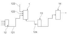
제 1 측면에 있어서, 본 발명은 RNA 시험관 내 전사를 위한 바이오리액터관 관한 것으로, 그 바이오리액터는,In the first aspect, the present invention relates to a bioreactor tube for RNA in vitro transcription, the bioreactor,
반응 베셀(reaction vessel); 및Reaction vessel; And
반응 베셀에 배치된 자석 유닛(magnet unit)을 구비한다.It has a magnet unit disposed on the reaction vessel.
반응 베셀은 자성 입자들, DNA 템플릿들, DNA 부동화 버퍼(immobilization buffer), DNA 자성 입자들 및 RNA 시험관 내 전사(In Vitro Transcription: IVT) 마스터 혼합물(master mix) 중 적어도 하나를 수용하는데 적합하다. 그에 의해, DNA 자성 입자들은 자유 유동 자성 입자들(free-floating magnetic particles)상에 고정된 DNA 템플릿들로 된다. 자석 유닛은 반응 베셀에 수용된 자성 입자들 및 DNA 자성 입자의 이동을 억류 또는 도입하도록 구성된다. 그러한 이동과 함께, 자성 입자 및/또는 DNA 자성 입자들의 혼합 또는 교반(stirring)이 유도될 수 있다. 따라서, 반응 베셀에 수용된 추가적인 구성 요소들의 개수에 의거하여, 자성 입자들 및/또는 DNA 자성 입자들 뿐만이 아니라, DNA 템플릿들, DNA 부동화 버퍼 및 IVT 마스터 혼합물 중 적어도 하나의 혼합 또는 교반이 자석 유닛에 의해 유도될 수 있다. 예를 들어, 반응 베셀에 수용된 구성 요소로서의 DNA 템플릿들 및 자유-유동 자성 입자들과 함께, 자석 유닛에 의해 유도된 자성 입자들의 혼합 및 교반은 혼합된 DNA 자성 입자를 이끌 수 있으며, DNA 자성 입자들은 자성 입자들상에 고정된 DNA 템플릿들이다. 자석 유닛에 의해 유도된 DNA 자성 입자들의 이동에 기인하여 DNA 자성 입자들과 IVT 마스터 혼합물이 혼합되거나 교반되는 경우, 그에 의해 수립된 DNA 자성 입자와 IVT 마스터 혼합물의 보다 균질한 혼합물(homogeneous mixture)이 템플릿 DNA에서 RNA로의 RNA 시험관 내 전사를 지원한다.The reaction vessel is suitable for receiving at least one of magnetic particles, DNA templates, DNA immobilization buffer, DNA magnetic particles, and RNA In Vitro Transcription (IVT) master mix. Thereby, the DNA magnetic particles become DNA templates immobilized on free-floating magnetic particles. The magnet unit is configured to confine or introduce movement of magnetic particles and DNA magnetic particles accommodated in the reaction vessel. With such movement, mixing or stirring of magnetic particles and/or DNA magnetic particles can be induced. Therefore, depending on the number of additional components accommodated in the reaction vessel, mixing or stirring not only magnetic particles and/or DNA magnetic particles, but also of at least one of DNA templates, DNA immobilization buffer, and IVT master mixture is performed in the magnetic unit. Can be induced by For example, mixing and agitation of magnetic particles induced by the magnet unit, together with DNA templates and free-flowing magnetic particles as constituent elements housed in the reaction vessel, can lead to the mixed DNA magnetic particles, and DNA magnetic particles Are DNA templates immobilized on magnetic particles. When the DNA magnetic particles and the IVT master mixture are mixed or agitated due to the movement of the DNA magnetic particles induced by the magnetic unit, a more homogeneous mixture of the DNA magnetic particles and the IVT master mixture established thereby is obtained. Supports RNA in vitro transcription from template DNA to RNA.
본 발명에 따른 바이오리액터는 제약 애플리케이션(예를 들어, 제약 핵산 생산)에 적절한 규제 조건하의 이용(GMP)에 적합할 수 있다. 바이오리액터는 액상 핵산 조성물, 바람직하기로는, 리보핵산(RNA) 조성물의 연속적인 생산 또는 반복적인 배치 생산을 할 수 있게 한다. 본 발명의 문맥에서, 용어 RNA는 임의 유형의 리보핵산(RNA)을 나타내는데 이용된다. 따라서, 용어 "RNA"는 롱-체인(long-chain) RNA, 코딩(coding) RNA, 비-코딩 RNA, ssRNA(single stranded RNA), dsRNA(double stranded RNA), linRNA(linear RNA), circRNA(circular RNA), mRNA(messenger RNA), RNA 올리고핵산염들(oligonucleotides), siRNA(small interfering RNA), shRNA(small hairpin RNA), asRNA(antisense RNA), CRISPR/Cas9 안내 RNA, 리보스위치들(riboswitchs), isRNA(immunostimulating RNA), 리보자임들(ribozymes), 앱타머들(aptamers), rRNA(ribosomal RNA), tRNA(transfer RNA), vRNA(viral RNA), 리트로바이러스(retroviral) RNA 또는 레플리콘(replicon) RNA, snRNA(small nuclear RNA), snoRNA(small nucleolar RNA), miRNA(microRNA), circRNA(circular RNA) 및 piRNA(Piwi-interacting RNA)로 이루어진 그룹으로부터 선택된 분자 또는 분자 종(molecule species)을 지칭한다. The bioreactor according to the invention may be suitable for use under regulatory conditions (GMP) suitable for pharmaceutical applications (eg pharmaceutical nucleic acid production). The bioreactor allows for continuous or repeated batch production of liquid nucleic acid compositions, preferably ribonucleic acid (RNA) compositions. In the context of the present invention, the term RNA is used to refer to any type of ribonucleic acid (RNA). Thus, the term "RNA" refers to long-chain RNA, coding RNA, non-coding RNA, ssRNA (single stranded RNA), dsRNA (double stranded RNA), linRNA (linear RNA), circRNA ( circular RNA), mRNA (messenger RNA), RNA oligonucleotides, siRNA (small interfering RNA), shRNA (small hairpin RNA), asRNA (antisense RNA), CRISPR/Cas9 guidance RNA, riboswitchs ), isRNA (immunostimulating RNA), ribozymes, aptamers, rRNA (ribosomal RNA), tRNA (transfer RNA), vRNA (viral RNA), retroviral RNA or replicon (replicon) a molecule or molecular species selected from the group consisting of RNA, small nuclear RNA (snRNA), small nucleolar RNA (snoRNA), microRNA (microRNA), circular RNA (circRNA), and piwi-interacting RNA (piRNA) Refers to.
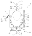
일 실시 예에 있어서, 반응 베셀의 내표면은 타원체 또는 달걀형의 내부 기하학적 구조를 가진다. 본 발명자들이 알게 된 것은, 타원 형상 또는 달걀형의 내부 기하학적 구조가 보다 좋은 혼합 결과를 가져올 수 있게 한다는 것이다. 추가적으로, 그러한 형상은 유체들의 보다 양호한 적하(drip off) 또는 배출(drain)를 할 수 있게 하고, 보다 양호한 세정 기능을 할 수 있게 한다. 후자는, 바이오리액터의 내표면에서 불리하게도 건조될 수 있는 방울들의 형성을 방지할 수 있다. 이것은, 예를 들어, 37℃ 이상의 온도에서 경화되거나 응고될 수 있는, 반응 베셀에 의해 수용된, 예를 들어, 단백질 잔류물에 특히 적용될 수 있다. In one embodiment, the inner surface of the reaction vessel has an ellipsoid or oval-shaped inner geometry. What the inventors have learned is that an oval-shaped or oval-shaped internal geometry can lead to better mixing results. Additionally, such a shape allows for better drip off or drain of fluids and a better cleaning function. The latter can prevent the formation of droplets that can undesirably dry out on the inner surface of the bioreactor. This is particularly applicable to, for example, protein residues received by the reaction vessel, which can be cured or solidified, for example at temperatures above 37°C.
일 실시 예에 있어서, 반응 베셀의 내표면은 계란 형상의 내부 기하학적 구조를 가진다. 그러한 계란 형상은 타원 형상의 문맥에서 서술한 장점과 동일한 장점을 제공하거나, 그 장점을 개선할 수 있다. 계란 형상은, 세정 프로세스 동안 반응 베셀 내표면에서의 자성 구슬들을 유지하기 위해, 혼합 또는 교반 동안 자성 구슬들의 최적의 압력 분배 및 최적의 작용을 제공할 수 있다. 계란 형상은, 예를 들어, 동일한 베이스 반경(base radius)을 가진 2개의 반-회전 타원체들(half-spheroids)로부터 획득될 수 있는데, 그 회전 타원체들 중 하나는 베이스 반경과 동일한 높이를 가진 반구체(half-sphere)이고, 다른 회전 타원체는 베이스 반경보다 큰 높이를 가진다. 대안적으로, 반응 베셀의 내표면은, 회전 타원체 형상, 특히, 구체 형상(shape of sphere)을 가지거나, 알약(pill) 형태를 가질 수 있다. 또한, 반응 베셀의 내표면은 계란 형상과 타원의 조합으로부터의 형상을 가질 수 있거나, 계란 형상과 원통 형상의 조합으로부터의 형상을 가질 수 있다. 그러한 조합에 의해 반응 베셀의 내표면의 한 부분은, 예를 들어, 계란 형상을 가진 반면, 그 내표면의 잔여 부분은, 예를 들어, 원통 형상을 가질 수 있다. In one embodiment, the inner surface of the reaction vessel has an oval-shaped inner geometry. Such an egg shape can provide the same advantages as described in the context of the ellipse shape, or can improve the advantages. The egg shape can provide an optimum pressure distribution and optimum action of the magnetic beads during mixing or stirring, in order to retain the magnetic beads at the inner surface of the reaction vessel during the cleaning process. The egg shape can be obtained, for example, from two half-spheroids with the same base radius, one of which is a half-spheroid with a height equal to the base radius. It is a half-sphere, and other spheroids have a height greater than the base radius. Alternatively, the inner surface of the reaction vessel may have a spheroid shape, in particular a shape of sphere, or may have a pill shape. Further, the inner surface of the reaction vessel may have a shape from a combination of an egg shape and an ellipse, or may have a shape from a combination of an egg shape and a cylindrical shape. By such a combination, one part of the inner surface of the reaction vessel may have, for example, an egg shape, while the remaining part of the inner surface may have, for example, a cylindrical shape.
일 실시 예에 있어서, 반응 베셀의 내표면은 구면 형상의 내부 기하학적 구조를 가질 수 있다. 그러한 구면 형상은 계란 형상 반응 베셀의 문맥에서 서술한 장점과 동일한 것을 제공하거나 그 장점을 개선할 수 있다.In one embodiment, the inner surface of the reaction vessel may have a spherical inner geometry. Such a spherical shape may provide the same advantages as described in the context of an egg-shaped reaction vessel or may improve the advantages.
일 실시 예에 있어서, 반응 베셀의 내표면은 에지들이 없는 형상(예를 들어, 둥근 에지들을 가진 직육면체)을 가질 수 있다. 유사하게, 이러한 형상은 방울(drop)들의 최적 배출을 지원하고, 그에 의해 반응 베셀에 수용된 유체의 단백질 잔여물의 경화를 방지한다. (에지없는) 그러한 형상은 효율적인 세정 절차를 할 수 있게 한다.In one embodiment, the inner surface of the reaction vessel may have a shape without edges (eg, a rectangular parallelepiped with rounded edges). Similarly, this shape supports optimal discharge of the drops, thereby preventing curing of the protein residues of the fluid contained in the reaction vessel. Such a shape (edgeless) allows for an efficient cleaning procedure.
일 실시 예에 있어서, 반응 베셀은 넓은 갭이나 틈이 없는 내표면을 가질 수 있다. 그 문맥에 있어서, 2㎛보다 큰 갭 또는 틈, 바람직하게는 1㎛보다 큰 갭 또는 틈, 보다 바람직하게는 0.8㎛보다 큰 갭 또는 틈이 "넓은" 갭 또는 틈인 것으로 간주된다. 보다 큰 갭이 미생물 오염 및 바이오필름(biofilm) 또는 잔유물에 틈새(niche)를 제공하기 때문에, (넓은 갭이 없는) 그러한 형상은 효과적인 세정 절차를 할 수 있게 한다.In one embodiment, the reaction vessel may have an inner surface without a wide gap or gap. In that context, a gap or gap greater than 2 μm, preferably greater than 1 μm, more preferably greater than 0.8 μm, is considered to be a “wide” gap or gap. Because the larger gap provides microbial contamination and niche in the biofilm or residue, such a shape (without wide gaps) allows for an effective cleaning procedure.
일 실시 예에 있어서, 자성 입자 및/또는 DNA 자성 입자들의 이동은, 반응 베셀에 수용된 입자들의 퇴적이 회피되도록 구성된다. 추가적으로 또는 대안적으로, 자성 입자 및/또는 DNA 자성 입자들의 이동은, 반응 베셀의 바닥에서의 퇴적이 방지될 수 있는 방식으로 그 입자들이 반응 베셀상에 포함된 입자들이 자유 유동 상태를 유지하도록 구성된다. 또한, 베셀내의 입자들을 자유 유동 상태로 유지시킴으로써 혼합 및 스웰링(swirling) 프로세스가 개선되고/되거나 구슬들의 응고가 방지되거나 감소된다. 바람직하게, 자성 입자들 및/또는 DNA 자성 입자들을 자유 유동 상태로 유지시키고/시키거나 자성 입자 및/또는 DNA 자성 입자들의 퇴적을 회피하면 바이오리액터에 있어서의 생화학적 반응, 즉, DNA 부동화 및 RNA 시험관 내 전사가 개선된다. In one embodiment, the movement of magnetic particles and/or DNA magnetic particles is configured such that deposition of particles accommodated in the reaction vessel is avoided. Additionally or alternatively, the movement of magnetic particles and/or DNA magnetic particles is configured such that the particles contained on the reaction vessel maintain a free flowing state in a way that deposition at the bottom of the reaction vessel can be prevented. do. In addition, by keeping the particles in the vessel in a free flowing state, the mixing and swelling process is improved and/or coagulation of the beads is prevented or reduced. Preferably, the biochemical reaction in the bioreactor, i.e. DNA immobilization and RNA, if the magnetic particles and/or DNA magnetic particles are kept in a free flowing state and/or the deposition of the magnetic particles and/or DNA magnetic particles is avoided. In vitro transcription is improved.
일 실시 예에 있어서, 바이오리액터의 자석 유닛은 전자석들의 어레이에 의해 주어진다. 후자는 반응 베셀의 외표면상에 또는 외표면에 근접하게 배치될 수 있다. 그 어레이중의 개별적인 전자석들은 개별적으로 스위칭 온 또는 오프될 수 있다. 그러한 방식에서는, 반응 베셀내에 수용된 자성 입자들 및/또는 DNA 자성 입자들의 혼합 및 스웰링이 개선되고 보다 잘 제어될 수 있다. 상기 전자석들의 어레이는, 바람직하게, 움직일 수 없으며, 바이오리액터 그 자체도 움직일 수 없고(쉐이킹(shaking) 없음), 혼합 또는 스웰링은 자성 입자 및/또는 DNA 자성 입자들과 자석 유닛의 공조에 의해 도입된다. In one embodiment, the magnet unit of the bioreactor is given by an array of electromagnets. The latter can be placed on or close to the outer surface of the reaction vessel. Individual electromagnets in the array can be individually switched on or off. In such a manner, mixing and swelling of magnetic particles and/or DNA magnetic particles contained in the reaction vessel can be improved and better controlled. The array of electromagnets, preferably, cannot move, the bioreactor itself cannot move (no shaking), and mixing or swelling is performed by the magnetic particles and/or the DNA magnetic particles and the magnetic unit. Is introduced.
대안적으로, 또 다른 실시 예에 있어서, 자석 유닛은 반응 베셀의 종축을 따라 종방향으로 이동 가능한 영구 자석 또는 전자석일 수 있다. 추가적으로 또는 그러한 종방향 이동 대신에, 영구 자석 또는 전자석이 반응 베셀을 향해 및 반응 베셀로부터 멀어지도록 횡방향으로 이동할 수 있다. 전자석들의 어레이의 경우와 유사하게, 종방향 및/또는 횡방향으로 이동할 수 있는 영구 자석 또는 전자석은 보다 양호한 혼합/스웰링 제어를 할 수 있게 하고 보다 양호한 혼합 결과를 가져온다. Alternatively, in another embodiment, the magnet unit may be a permanent magnet or an electromagnet that is movable longitudinally along the longitudinal axis of the reaction vessel. Additionally or instead of such longitudinal movement, a permanent magnet or electromagnet can be moved transversely toward and away from the reaction vessel. Similar to the case of an array of electromagnets, a permanent magnet or electromagnet that can move longitudinally and/or transversely allows better mixing/swelling control and results in better mixing results.
대안적으로 또 다른 실시 예에 있어서, 자석 유닛은 전자석과 바람직하게 적어도 하나의 유도 코일(induction coil)에 의해 주어진다. 이 경우, 자석 유닛은 반응 베셀의 종축을 따라 종방향으로 이동 가능하다. 추가적으로, 자석 유닛은 반응 베셀의 종축을 중심으로 회전 가능하다.Alternatively in another embodiment, the magnet unit is provided by an electromagnet and preferably at least one induction coil. In this case, the magnet unit is movable in the longitudinal direction along the longitudinal axis of the reaction vessel. Additionally, the magnet unit is rotatable about the longitudinal axis of the reaction vessel.
적절히, 자석 유닛은 적어도 하나의 헬름홀츠 코일(Helmholtz coil) 형태로 배열될 수 있다.Suitably, the magnet units may be arranged in the form of at least one Helmholtz coil.
반응 베셀 근처의 자석 유닛의 위치를 자석 유닛과 반응 베셀간의 거리라 지칭하며, 이것은 자석 유닛이 턴 온(turn on)될 때 반응 베셀 내부에 적당한 자기장이 수립되게 한다. 자기장은, 자성 입자들의 스웰링/혼합이 유도될 수 있고/있거나 자성 입자들이 반응 베셀의 내표면상에 억류될 수 있게 하는 세기 및 형태를 가진다. The position of the magnet unit near the reaction vessel is referred to as the distance between the magnet unit and the reaction vessel, which causes a suitable magnetic field to be established inside the reaction vessel when the magnet unit is turned on. The magnetic field has an intensity and shape such that swelling/mixing of magnetic particles can be induced and/or magnetic particles can be trapped on the inner surface of the reaction vessel.
일 실시 예에 있어서, 자석 유닛은 반응 베셀의 종축을 중심으로 회전하도록 구성되며, 자석 유닛의 회전 방향은 혼합 동안에 절환 가능하다. 자석 유닛은 반응 베셀의 종축에 대해 방사 방향으로 자성 입자들을 유도함에 의해, 반응 베셀의 방사 방향으로 자성 입자들의 이동을 도입할 수 있다. 자기력은 회전을 유발시키기 위해 반응 베셀을 중심으로 자석 유닛을 회전시킴으로써 정적 또는 동적으로 생성될 수 있으며, 그에 따라 자성 입자들의 혼합이 이루어진다. 자석 유닛의 회전 방향은 반응 베셀의 종축에 대해 시계 방향 또는 반 시계 방향이고/이거나 대안적으로 변경될 수 있다. 따라서, 자성 입자들은 무접촉 방식으로 계속적으로 자유 유동 상태일 수 있고, 그에 따라, 구성 요소들의 혼합이 개선될 수 있다. 자석 유닛의 회전이 멈추면 곧바로, 자성 입자들(예를 들어, DNA 자성 입자들)은 반응 베셀의 내표면에 억류되며, 더이상 회전하지 않게 된다. 따라서, 자석 유닛은 (ⅰ) 상술한 바와 같이 자성 입자들의 이동을 도입하기 위해 반응 베셀의 종축을 중심으로 회전하고, (ⅱ) 회전이 멈추면 자성 입자들을 억류하도록 구성된다.In one embodiment, the magnet unit is configured to rotate about the longitudinal axis of the reaction vessel, and the rotation direction of the magnet unit is switchable during mixing. The magnet unit may introduce movement of the magnetic particles in the radial direction of the reaction vessel by inducing the magnetic particles in the radial direction with respect to the longitudinal axis of the reaction vessel. The magnetic force can be generated statically or dynamically by rotating the magnet unit around the reaction vessel to induce rotation, and the magnetic particles are mixed accordingly. The direction of rotation of the magnet unit is clockwise or counterclockwise with respect to the longitudinal axis of the reaction vessel and/or can alternatively be changed. Thus, the magnetic particles can be in a free flowing state continuously in a contactless manner, and accordingly, mixing of the components can be improved. As soon as the magnet unit stops rotating, magnetic particles (eg, DNA magnetic particles) are trapped on the inner surface of the reaction vessel and will no longer rotate. Accordingly, the magnet unit is configured to (i) rotate around the longitudinal axis of the reaction vessel to introduce movement of the magnetic particles as described above, and (ii) hold the magnetic particles when the rotation stops.
일 실시 예에 있어서, 자석 유닛은 자기 링(magnetic ring)을 구비하며, 자기 링은 반응 베셀을 에워싸도록 고안된다. 반응 베셀을 중심으로 하여 자석 유닛을 쉽게 어셈블링(assembling)하고 회전시킬 수 있도록 하기 위하여, 자석 유닛은 링 형상으로 형성될 수 있다. 다시 말해, 반응 베셀은, 자석 유닛이 반응 베셀을 에워싸도록 링 형상의 자석 유닛의 중심에 배치될 수 있다. In one embodiment, the magnet unit has a magnetic ring, which is designed to surround the reaction vessel. In order to be able to easily assemble and rotate the magnet unit around the reaction vessel, the magnet unit may be formed in a ring shape. In other words, the reaction vessel may be disposed at the center of the ring-shaped magnet unit so that the magnet unit surrounds the reaction vessel.
일 실시 예에 있어서, 자기 링은, 제 1 막대(rod)와 제 2 막대의 자유 단부들(free ends)이 서로 마주하도록, 자기 링의 내부 원주에서 자기 링의 중심으로 연장되는 적어도 제 1 막대와 제 2 막대를 구비한다. 일 실시 예에 있어서, 제 1 막대의 자유 단부는 N극을 가진 자석을 구비하며, 제 2 막대의 자유 단부는 S극을 가진 자석을 구비한다. In one embodiment, the magnetic ring is at least a first rod extending from the inner circumference of the magnetic ring to the center of the magnetic ring such that free ends of the first rod and the second rod face each other. And a second rod. In one embodiment, the free end of the first rod has a magnet with an N pole, and the free end of the second rod has a magnet with an S pole.
디스크 형상 또는 링 형상의 자석 유닛은 자기 링의 원주 방향으로 배열된 자석을 구비할 수 있다. 그 자석은, 자석과 반응 베셀간의 갭을 줄이기 위해, 자기 링에 접촉하여 직접 배치되거나 자기 링의 중심에 배치된 반응 베셀에 보다 밀접하게 자기 링으로부터 오프셋되어 배치될 수 있다. 링으로부터 멀리 자석을 유지시키기 위해, 내표면에 접속되고 링의 중심으로 연장되는 자석 홀더(magnet holder)가 이용될 수 있다. 자석 홀더는 홀딩 막대(holding rod)로서 고안되며, 그에 따라, 홀딩 막대의 일측 단부는 자기 링의 내부 원주에 부착되고 홀딩 막대의 다른측 단부는 자석을 지탱하게 된다. 자기 링과 홀딩 막대는 개별적으로 생산되어, 서로 부착되거나 예를 들어 주조(molding)에 의해 일체로 제조될 수 있다.The disk-shaped or ring-shaped magnet unit may include magnets arranged in the circumferential direction of the magnetic ring. The magnet may be placed directly in contact with the magnetic ring, or offset from the magnetic ring more closely to the reaction vessel disposed at the center of the magnetic ring, in order to reduce the gap between the magnet and the reaction vessel. To keep the magnet away from the ring, a magnet holder connected to the inner surface and extending to the center of the ring can be used. The magnet holder is designed as a holding rod, whereby one end of the holding rod is attached to the inner circumference of the magnetic ring and the other end of the holding rod supports the magnet. The magnetic ring and holding rod can be produced separately and attached to each other or made integrally, for example by molding.
자성 입자들의 이동을 효과적으로 유도하기 위하여, 자기 링은 자기 링의 원주를 따라 서로 이격된 적어도 2개의 막대들을 구비할 수 있으며, 막대들의 자유 단부들이 서로 마주한다. 막대들의 각각의 자유 단부에, N극과 S극을 가진 영구 자석이 교번적으로 부착될 수 있다. 따라서, 자기 링을 회전시킬 때, 자성 입자들은 반응 베셀의 주변에 회전 가능하게 유도될 수 있으며, 그에 따라 반응 베셀내의 구성 요소들의 개선된 혼합이 이루어진다.In order to effectively induce the movement of magnetic particles, the magnetic ring may have at least two rods spaced apart from each other along the circumference of the magnetic ring, and the free ends of the rods face each other. At each free end of the rods, permanent magnets having N and S poles may be attached alternately. Thus, when rotating the magnetic ring, the magnetic particles can be rotatably induced around the reaction vessel, resulting in an improved mixing of the components within the reaction vessel.
자성 입자들을 효과적으로 억류하기 위하여, 반응 베셀내의 구성 요소들이 혼합된 후 자기 링의 회전이 중지될 수 있다.In order to effectively retain the magnetic particles, the rotation of the magnetic ring can be stopped after the components in the reaction vessel are mixed.
또 다른 실시 예에 있어서, 자기 링은, 다수의 막대들을 구비할 수 있으며, 다수의 막대들은, 자기 링의 내부 원주에서 자기 링의 중심으로 연장되고, 서로 균등하게 이격된 스타(star) 형상으로 배열된다. 바람직하게, N극을 가진 자석과 S극을 가진 자석이 막대들의 각 자유 단부에 교번적으로 배열된다.In another embodiment, the magnetic ring may include a plurality of rods, and the plurality of rods extend from the inner circumference of the magnetic ring to the center of the magnetic ring, and have a star shape that is evenly spaced from each other. Are arranged. Preferably, a magnet with an N pole and a magnet with an S pole are alternately arranged at each free end of the rods.
바람직한 실시 예에 있어서, 자기 링은 짝수개의 막대들을 구비하며, 다수의 막대들과, 그에 따른 막대들의 각 자유 단부에 부착된 다수의 자석들은 이질적(heterogeneous) 또는 주기적 자기장을 제공하기 위해 페어(pair)를 이루는 방식으로 배열된다. 또한, 자기 링의 원주를 따라 균등하게 이격된 막대들은 반응 베셀내부에 자성 입자들을 유도하는 대칭적 자기장이 이루어질 수 있게 한다. In a preferred embodiment, the magnetic ring has an even number of rods, and a plurality of rods and thus a plurality of magnets attached to each free end of the rods are paired to provide a heterogeneous or periodic magnetic field. ). In addition, the rods evenly spaced along the circumference of the magnetic ring enable a symmetrical magnetic field to induce magnetic particles inside the reaction vessel.
일 실시 예에 있어서, 자기 링과 막대들은 주변 구성 요소들을 자기장으로부터 차폐하는 적층 스택(laminated stack)을 형성하도록 구성된다. 자기 링과 막대들은 자화 가능한(magnetisable) 다수의 적층 전기 시트들(laminated electrical sheets)로 이루어질 수 있다. 적층 전기 시트들은 전기 스틸(electrical steel)을 구비할 수 있으며, 전기적 절연을 위해 이용될 수 있다. 적층 스택은 막대들의 자유 단부들에 부착된 영구 자석들에 의해 생성된 자기장을 차단하고 반응 베셀을 제외한 다른 디바이스들에게는 영향을 미치지 않는다. 자기장의 차폐는, 특히 바람직하며, 자기장에 의해 영향을 받을 수 있는 다른 디바이스들/구성 요소들을 구비한 장치에 있어서 바이어리액터의 집적화가 이루어질 수 있게 한다. In one embodiment, the magnetic rings and rods are configured to form a laminated stack that shields surrounding components from the magnetic field. The magnetic rings and rods may consist of a number of magnetisable laminated electrical sheets. Laminated electrical sheets may have electrical steel and may be used for electrical insulation. The stacked stack blocks the magnetic field created by the permanent magnets attached to the free ends of the rods and has no effect on other devices except the reaction vessel. Shielding of the magnetic field is particularly desirable and allows integration of the bias reactor in a device with different devices/components that can be affected by the magnetic field.
일 실시 예에 있어서, 자기 링은 자기 링의 내부 원주에서 자기 링의 중심으로 연장되는 다수의 가이드 플레이트들(guide plates)을 구비한다. 바람직하게, 각각의 가이드 플레이트는 자기장을 생성하도록 구성된 전기 코일(electric coil)을 구비한다. 자기 링은, 바람직하게, 전자기 코일에 의해 자기장을 생성하는 다수의 전자석들 중 적어도 하나를 구비할 수 있다. 가이드 플레이트는 자기 링의 원주를 따라 스타 형상으로 배열되고 자기 링의 중심으로 연장되며, 거기에는 반응 베셀이 배치될 수 있다. 전자기 코일들은 전류량을 제어함에 의해 자기장이 신속하게 변경되게 한다. In one embodiment, the magnetic ring has a plurality of guide plates extending from the inner circumference of the magnetic ring to the center of the magnetic ring. Preferably, each guide plate has an electric coil configured to generate a magnetic field. The magnetic ring may preferably have at least one of a number of electromagnets that generate a magnetic field by means of an electromagnetic coil. The guide plate is arranged in a star shape along the circumference of the magnetic ring and extends to the center of the magnetic ring, on which a reaction vessel can be arranged. Electromagnetic coils allow the magnetic field to change rapidly by controlling the amount of current.
일 실시 예에 있어서, 자기 링은 냉각 수단을 가진 하우징(housing)내에 배열된다. 냉각 수단은 자기 링의 원주를 따라 자기 링의 하우징내에 집적화됨으로써, 전자기 코일들을 통과하는 높은 전류들에 의해 유발된 열을 제거한다. 냉각 수단은 물과 같은 냉각 매체가 순환하는 냉각 채널일 수 있다. 냉각 수단은, 바람직하게, 전자기 코일을 구비한 자기 링들내에 집적화된다. 냉각 수단은 영구 자석을 구비한(전자기 코일을 구비하지 않은) 자기 링들내에 집적화되지 않을 수도 있다.In one embodiment, the magnetic ring is arranged in a housing with cooling means. The cooling means are integrated in the housing of the magnetic ring along the circumference of the magnetic ring, thereby removing heat caused by high currents passing through the electromagnetic coils. The cooling means may be a cooling channel through which a cooling medium such as water circulates. The cooling means are preferably integrated in magnetic rings with an electromagnetic coil. The cooling means may not be integrated in magnetic rings with permanent magnets (without electromagnetic coils).
일 실시 예에 있어서, 자석 유닛은, 반응 베셀의 종축을 중심으로 자기 링을 회전시키도록 구성된 제 1 구동 수단과, 반응 베셀의 종축을 따라 종방향으로 자기 링을 이동시키도록 구성된 제 2 구동 수단을 추가로 구비한다. 자기 링은 반응 베셀의 종축 방향으로 이동하는 프레임(frame)에 의해 지탱될 수 있다. 따라서, 자기 링이 수직하게 회전하고 이동할 때 반응 베셀의 종방향과 방사 방향으로 자기장이 제공되고 변경될 수 있으며, 이는 반응 베셀내의 구성 요소들의 보다 양호한 균질 혼합을 이끈다.In one embodiment, the magnet unit includes a first driving means configured to rotate the magnetic ring about a longitudinal axis of the reaction vessel, and a second driving means configured to move the magnetic ring in a longitudinal direction along the longitudinal axis of the reaction vessel It additionally includes. The magnetic ring can be supported by a frame moving in the longitudinal direction of the reaction vessel. Thus, when the magnetic ring rotates and moves vertically, the magnetic field can be provided and changed in the longitudinal and radial directions of the reaction vessel, which leads to a better homogeneous mixing of the components in the reaction vessel.
자기 링을 회전시키는 구동 수단과 수직 방향으로 자기 링을 이동시키는 구동 수단은 개별적으로 제공될 수 있다. 자기 링을 회전시키는 제 1 구동 수단은 자기 링에 직접 배열되고 반응 베셀 위에 배치될 수 있는 반면, 자기 링을 수직으로 이동시키는 제 2 구동 수단은 자기 링을 고정되게 지탱하고 자기 링이 수직하게 이동할 수 있게 하는 프레임을 통해 자기 링에 접속될 수 있다. The drive means for rotating the magnetic ring and the drive means for moving the magnetic ring in the vertical direction may be provided separately. The first driving means for rotating the magnetic ring can be arranged directly on the magnetic ring and disposed on the reaction vessel, while the second driving means for moving the magnetic ring vertically supports the magnetic ring fixedly and the magnetic ring moves vertically. It can be connected to the magnetic ring through a frame to enable it.
일 실시 예에 있어서, 반응 베셀은 상자성(paramagnetic)이며, 따라서, 자성 입자들과 DNA 자성 입자들은 반응 베셀에 배치된 자석 유닛과 상자성 베셀의 공조에 의해 내부 반응 베셀 벽상에 감금된다. 그 때문에, 전체 반응 베셀은 상자성일 수 있으며, 또는 반응 베셀의 내표면이 상자성 물질 또는 자기적 도전 물질(magnetically conductive material)을 구비함으로써, 상자성으로 될 수 있다. 용어 "자화 가능"은, 본 발명의 전체에 걸쳐, 자성 입자들이 반응 베셀 벽에 끌어당겨져 감금되도록, 반응 베셀 또는 그의 내표면이 일시적으로 자화되는 것을 나타낸다. 그러나, 반응 베셀 또는 그의 내표면의 자화는, 반응 베셀 벽에 감금된 자성 입자들 또는 DNA 자성 입자들이 해제되도록 역전될 수 있다. 그러므로, 자석 유닛을 스위칭 온함에 의해 바이오리액터의 물질 및/또는 바이오리액터의 내표면이 영구적으로 자화되지 않는 것(즉, 강자성(ferromagnetic)이 아님)이 중요하다.In one embodiment, the reaction vessel is paramagnetic, and thus, magnetic particles and DNA magnetic particles are confined on the inner reaction vessel wall by air conditioning between the magnetic unit disposed in the reaction vessel and the paramagnetic vessel. For that reason, the entire reaction vessel can be paramagnetic, or can be made paramagnetic by the inner surface of the reaction vessel having a paramagnetic material or a magnetically conductive material. The term “magnetizable” denotes that throughout the present invention, the reaction vessel or its inner surface is temporarily magnetized such that magnetic particles are attracted and confined to the reaction vessel wall. However, the magnetization of the reaction vessel or its inner surface can be reversed so that the magnetic particles or DNA magnetic particles confined to the reaction vessel wall are released. Therefore, it is important that the material of the bioreactor and/or the inner surface of the bioreactor are not permanently magnetized (ie, not ferromagnetic) by switching on the magnet unit.
따라서, 바람직한 실시 예에 있어서, 반응 베셀은 상자성이다. 다른 실시 예에 있어서, 반응 베셀은 자화되지 않으면서 자기장의 침투를 허용하도록 구성된다.Thus, in a preferred embodiment, the reaction vessel is paramagnetic. In another embodiment, the reaction vessel is configured to allow penetration of the magnetic field without being magnetized.
일 실시 예에 있어서, 자석 유닛은 자성 입자들 및/또는 DNA 자성 입자들을 혼합하기 위해 주기적으로 활성화되도록 구성된다. 자석 유닛의 주기적 활성화는 자석 유닛의 연속적인 활성화에 비해 구성 요소들의 개선된 혼합을 야기한다. 구성 요소들의 개선된 혼합을 야기하는 자석 유닛의 주기적 활성화는 자성 입자 또는 DNA 자성 입자들의 자유 유동을 유지시키는 방식으로 조정되어야 하며, 생화학적 반응이 최적화된 방식으로 발생하는 방식으로 혼합이 이루어질 수 있도록 조정되어야 한다(RNA 합성이 발생하는 생화학 반응에 수반된, 예를 들어, RNA 시험관 내 전사에 수반된 모든 구성 요소들이 혼합되어 서로 접촉함). 마찬가지로, 원치않은 전단력(shear force)이 최소화되고 열의 전개(heat development)가 감소되는 방식으로 (열의 전개는 자기 에너지가 열로 변환됨에 의해 유도되거나 마찰열에 의해 유도될 수 있음) 주기적으로 활성화되는 자석과, DNA 자성 입자들/자성 입자들에 의해 유도되는 혼합을 조정하는 것이 중요하다. In one embodiment, the magnet unit is configured to be activated periodically to mix magnetic particles and/or DNA magnetic particles. The periodic activation of the magnet unit results in an improved mixing of the components compared to the continuous activation of the magnet unit. The periodic activation of the magnetic unit, which results in an improved mixing of the components, must be adjusted in such a way that the free flow of magnetic particles or DNA magnetic particles is maintained, so that mixing can take place in such a way that the biochemical reaction takes place in an optimized manner. It must be coordinated (all components involved in the biochemical reaction in which RNA synthesis occurs, e.g., involved in RNA transcription in vitro, are mixed and brought into contact with each other). Similarly, a magnet that is periodically activated in such a way that undesired shear forces are minimized and heat development is reduced (heat development may be induced by conversion of magnetic energy into heat or may be induced by frictional heat) and In other words, it is important to adjust the mixing induced by the DNA magnetic particles/magnetic particles.
일 실시 예에 있어서, 자석 유닛은 (DNA 자성 입자들 형태로 제공된) 동일 DNA 템플릿들상에서의 2개 이상의 후속하는 RNA 시험관 내 전사들간에 DNA 자성 입자들을 억류하도록 활성화되는 구성을 가진다. 그러한 억류는 반응 베셀의 내표면에 DNA 자성 입자들을 감금하게 하는 반응 베셀의 자화와 연관될 수 있으며/있거나, 반응 베셀내의 자화 가능하되 화학적으로 불활성인 막대들 또는 구체들의 자화와 연관될 수 있다. 바람직하게, 그러한 억류는 2 이상의 RNA 시험관 내 전사 반응시에 DNA 자성 입자들의 재-사용을 가능하게 하며, 그에 의해, RNA 생성물의 템플릿 공급 스케일 및 비용을 저감함으로써 생산 시간을 감축시킨다(DNA 템플릿들은 여러번 이용될 수 있음).In one embodiment, the magnetic unit has a configuration that is activated to retain DNA magnetic particles between two or more subsequent RNA in vitro transcriptions on the same DNA templates (provided in the form of DNA magnetic particles). Such detention may be associated with the magnetization of the reaction vessel to confine the DNA magnetic particles to the inner surface of the reaction vessel and/or may be associated with the magnetization of magnetizable but chemically inert rods or spheres within the reaction vessel. Preferably, such detention allows re-use of DNA magnetic particles in two or more RNA in vitro transcription reactions, thereby reducing production time by reducing the template supply scale and cost of the RNA product (DNA templates are Can be used multiple times).
일 실시 예에 있어서, 자석 유닛은 자성 입자들과 DNA 자성 입자들을 제거하도록 활성화되는 구성을 가진다. 자성 입자들 및 DNA 자성 입자들의 그러한 제거는 반응 베셀의 세정을 위한 것일 수 있다. DNA 자성 입자들의 제거는, (예를 들어, 자기 링의 회전을 중지시킴에 의해) 마지막 RNA 시험관 내 전사 반응 후에 실행될 수 있다. DNA 자성 입자들의 그러한 제거는, 예를 들어, DNA 분해 효소를 통한 효소 증해없이 DNA가 제거될 수 있어서, 최종 RNA 생성물에 있어서 DNA 오염과 효소 오염을 감소시키고(DNA 증해 생성물이 없고, DNA 분해 효소가 없음) RNA 생성물의 비용을 줄이게 된다(최종 생성물에 있어서 DNA 분해 효소의 제어가 필요치 않고, DNA 분해 효소가 필요치 않음)는 장점이 있다. In one embodiment, the magnet unit has a configuration that is activated to remove magnetic particles and DNA magnetic particles. Such removal of magnetic particles and DNA magnetic particles may be for cleaning of the reaction vessel. Removal of DNA magnetic particles can be performed after the last RNA in vitro transcription reaction (eg, by stopping the rotation of the magnetic ring). Such removal of magnetic DNA particles, for example, can remove DNA without enzymatic digestion via DNA degrading enzymes, thereby reducing DNA contamination and enzymatic contamination in the final RNA product (no DNA digestion products, DNA degrading enzymes There is an advantage of reducing the cost of the RNA product (there is no need to control the DNA-degrading enzyme in the final product, and no DNA-degrading enzyme is required).
일 실시 예에서는, 자성 입자들과 DNA 자성 입자들에 대한 기계적 움직임 도입 수단이 구비되지 않는다. 이러한 실시 예에 따르면, 반응 베셀내의 수용된 구성 요소들의 혼합 또는 교반을 유도할 수 있는, 추가적인 기계적 교반기(stirrers) 또는 휘젓개(agitator)가 없으며, 그에 따라, 그 혼합은 자석 유닛에 의해서만 유도된다. 이것은, 반응 베셀 내부에 배치된 기계적 움직임 도입 수단이 원치않은 침전(예를 들어, 기계적 교반 수단상에의 침전)의 형성을 유발할 수 있기 때문에, 본 발명의 문맥에서 특히 바람직하다. 또한, 기계적 움직임 도입 수단이 없으면, 바이오리액터의 세정이 개선된다(표면 감소, 반응 베셀내에 에지 없음). In one embodiment, a means for introducing mechanical motion for magnetic particles and DNA magnetic particles is not provided. According to this embodiment, there are no additional mechanical stirrers or agitators, which can induce mixing or agitation of the contained components in the reaction vessel, so that the mixing is induced only by the magnetic unit. This is particularly preferred in the context of the present invention, since the means for introducing mechanical motion arranged inside the reaction vessel can lead to the formation of undesired precipitation (eg precipitation on the mechanical stirring means). In addition, without the means for introducing mechanical motion, the cleaning of the bioreactor is improved (reduced surface, no edges in the reaction vessel).
대안적인 실시 예에 있어서, 자성 입자들 및 DNA 자성 입자들의 기계적 움직임 도입 수단은 쉐이커(shaker)(예를 들어, 궤도 쉐이커) 형태로 구성되는데, 그 쉐이커는 바람직하게 반응 베셀 외부에 배치된다. In an alternative embodiment, the means for introducing the mechanical motion of the magnetic particles and the DNA magnetic particles is configured in the form of a shaker (eg, an orbital shaker), which shaker is preferably arranged outside the reaction vessel.
일 실시 예에 있어서, 반응 베셀내에 수용된 구성 요소들의 혼합 또는 교반은 (ⅰ) 자성 입자들과 자석 유닛의 공조, (ⅱ) 기계적 움직임 도입 수단, 및/또는 (ⅲ) 반응 베셀 내부로의 프로세스 가스 또는 프로세스 유체의 지향의 조합에 의해 도입될 수 있다. In one embodiment, mixing or stirring of the constituent elements contained in the reaction vessel is (i) air conditioning of the magnetic particles and the magnetic unit, (ii) a means for introducing mechanical movement, and/or (iii) a process gas into the reaction vessel. Or it can be introduced by a combination of the orientation of the process fluid.
일 실시 예에 있어서, 반응 베셀은 반응 베셀의 종방향으로, 적어도 부분적으로 반응 베셀의 내표면을 따라 배열된 적어도 하나의 흐름 차단기(flow breaker)를 구비한다. 흐름 차단기는 반응 베셀내의 구성 요소들의 균일한 흐름을 교란시킬 수 있으며, 그에 따라, 혼합을 개선한다. 또한, 흐름 차단기는, 자기 링이 회전을 멈추고/멈추거나 회전 방향을 변경할 때, 자성 입자들의 퇴적을 방지할 수 있다. 따라서, 흐름 차단기는, 특히, 반응 베셀의 종방향에 수직한 수평 방향으로, 자성 입자들이 누적될 수 있는, 어떠한 그루브(groove) 없이 연속성을 가지고 고안될 수 있다. In one embodiment, the reaction vessel has at least one flow breaker arranged in the longitudinal direction of the reaction vessel, at least partially along the inner surface of the reaction vessel. The flow blocker can disturb the uniform flow of the components within the reaction vessel, thus improving mixing. Further, the flow blocker can prevent the deposition of magnetic particles when the magnetic ring stops rotating and/or changes the direction of rotation. Thus, the flow blocker can be designed with continuity without any grooves, in which magnetic particles can accumulate, in particular in a horizontal direction perpendicular to the longitudinal direction of the reaction vessel.
흐름 차단기는 반응 베셀의 방사 방향으로 반응 베셀의 내표면으로부터 돌출되어 반응 베셀의 종방향을 따라 연장된다. 흐름 차단기는 반응 베셀의 상부에서 하부로 계속적으로 연장되거나, 반응 베셀의 종방향을 따라 서로 개별적으로 배열된 다수의 소자들을 구비할 수 있다. 따라서, 흐름 차단기는 바람직하게 서로간에 이격된 다수의 돌출부들을 구비할 수 있다. The flow blocker protrudes from the inner surface of the reaction vessel in the radial direction of the reaction vessel and extends along the longitudinal direction of the reaction vessel. The flow interrupter may have a plurality of elements that extend continuously from the top to the bottom of the reaction vessel, or are arranged individually from each other along the longitudinal direction of the reaction vessel. Thus, the flow breaker may preferably have a plurality of protrusions spaced from each other.
일 실시 예에 있어서, 반응 베셀은 반응 베셀의 원주를 따라 서로 이격된 2개의 흐름 차단기들을 구비한다. 반응 베셀은 적어도 하나, 정확하게는 2개 이상의 흐름 차단기들을 구비할 수 있다. 흐름 차단기들은, 바람직하게, 반응 베셀의 방사 방향으로 반응 베셀의 내표면을 따라 균등하게 분포됨으로써, 혼합을 개선하고, 자성 입자들의 퇴적을 방지한다.In one embodiment, the reaction vessel has two flow breakers spaced apart from each other along the circumference of the reaction vessel. The reaction vessel may have at least one, precisely two or more flow breakers. The flow blockers are preferably evenly distributed along the inner surface of the reaction vessel in the radial direction of the reaction vessel, thereby improving mixing and preventing deposition of magnetic particles.
일 실시 예에 있어서, 흐름 차단기는 립(rib) 형상이며, 립 형상의 흐름 차단기는, 바람직하게, T 형상 또는 L 형상의 단면(cross section)을 구비할 수 있다. 내표면에서 반응 베셀의 중심 방향으로 돌출하는 흐름 차단기는 반응 베셀의 곡선형의 내표면을 따라 아크 형상(arc shape)으로 형성될 수 있으며, 반응 베셀의 타원형의 내부 기하학적 구조를 따라 다수의 곡률 반경들을 구비한다. 반응 베셀의 종축에 대한 흐름 차단기의 방사 단면은 가변될 수 있다. 예를 들어, 방사 단면은 T 형상, L 형상 또는 볼록 형상으로서 형성될 수 있다. 흐름 차단기의 방사 단면의 돌출 길이는 반응 베셀의 상부에서 하부로 내표면을 따라 가변될 수 있다. 일 실시 예에 있어서, 흐름 차단기는 물결 형상일 수 있다. 립 형상의 흐름 차단기는 반응 베셀의 내표면을 따르는 파-형상(wave-shap)일 수 있으며, 이는 자성 입자들의 퇴적을 방지한다. 물결 형상의 흐름 차단기의 파-형상 표면은 반응 베셀의 내표면에 수직하게 정렬될 수 있다.In one embodiment, the flow circuit breaker has a rib shape, and the lip shape flow circuit breaker may preferably have a T-shaped or L-shaped cross section. The flow blocker protruding from the inner surface toward the center of the reaction vessel may be formed in an arc shape along the curved inner surface of the reaction vessel, and a plurality of radii of curvature along the elliptical inner geometry of the reaction vessel Have them. The radial cross section of the flow blocker with respect to the longitudinal axis of the reaction vessel can be varied. For example, the radial cross section may be formed as a T shape, an L shape, or a convex shape. The protruding length of the radial section of the flow blocker can be varied along the inner surface from top to bottom of the reaction vessel. In one embodiment, the flow breaker may have a wavy shape. The lip-shaped flow blocker may be wave-shap along the inner surface of the reaction vessel, which prevents the deposition of magnetic particles. The wave-shaped surface of the wave-shaped flow blocker can be aligned perpendicular to the inner surface of the reaction vessel.
일 실시 예에 있어서, 반응 베셀의 내표면과 외표면 사이에 반응 베셀의 온도를 조정하기 위한 온도 소자가 배치된다. 다시 말해, 반응 베셀은 내표면과 외표면 사이에 온도 소자의 집적화가 가능하도록 한 고체 물질로 이루어진 두꺼운 벽을 구비할 수 있다. 따라서, 반응 베셀의 가열 및 냉각에 관한 고속 온도 조정이 도모될 수 있다.In one embodiment, a temperature element for adjusting the temperature of the reaction vessel is disposed between the inner surface and the outer surface of the reaction vessel. In other words, the reaction vessel may have a thick wall made of a solid material that enables integration of temperature elements between the inner and outer surfaces. Therefore, high-speed temperature adjustment regarding heating and cooling of the reaction vessel can be achieved.
일 실시 예에 있어서, 온도 소자는 반응 베셀의 방사 방향으로 반응 베셀을 적어도 부분적으로 나선형으로 에워싸는 열 교환 채널을 구비한다. 열 교환 채널은 내표면과 외표면 사이에 집적화될 수 있고 반응 베셀에 있어서의 온도를 조정할 수 있다. 효율적이고 일정한 가열 또는 냉각을 제공하기 위하여, 열 교환 채널은 반응 베셀을 완벽하게 에워쌀 수 있으며, 열 교환 매체가 열 교환 채널내에서 흐를 수 있다. In one embodiment, the temperature element has a heat exchange channel at least partially helically surrounding the reaction vessel in the radial direction of the reaction vessel. The heat exchange channels can be integrated between the inner and outer surfaces and the temperature in the reaction vessel can be adjusted. In order to provide efficient and constant heating or cooling, the heat exchange channel can completely surround the reaction vessel, and the heat exchange medium can flow within the heat exchange channel.
일 실시 예에 있어서, 열 교환 채널은 제 1 단부 및 제 2 단부를 구비하며, 제 1 단부는 반응 베셀의 상부 부분에 배열되고, 제 2 단부는 반응 베셀의 하부 부분에 배열된다. 나선형으로 배열된 열 교환 채널은 열 교환 매체의 유입 및/또는 유출을 위한 적어도 2개의 포트(port)들을 가질 수 있으며, 하나의 포트가 반응 베셀의 상부 부분에 배열되고 다른 포트가 반응 베셀의 하부 부분에 배열되어, 중력을 적용할 때, 열 교환 매체의 효율적인 분배를 도모할 수 있게 한다. In one embodiment, the heat exchange channel has a first end and a second end, the first end being arranged in the upper portion of the reaction vessel, and the second end being arranged in the lower portion of the reaction vessel. The helically arranged heat exchange channel may have at least two ports for the inflow and/or outflow of the heat exchange medium, one port is arranged in the upper part of the reaction vessel and the other port is the lower part of the reaction vessel. It is arranged in part, when applying gravity, it makes it possible to achieve efficient distribution of the heat exchange medium.
일 실시 예에 있어서, 열 교환 채널 및/또는 반응 베셀은 적층 제조 프로세스(additive manufacturing process)에 의해 제조된다. 따라서, 반응 베셀의 내표면과 외표면 사이에서 반응 베셀을 나선형으로 에워싼 열 교환 채널을 포함하는 반응 베셀의 복잡한 기하학적 구조가 쉽게 실현될 수 있다. In one embodiment, the heat exchange channels and/or reaction vessels are manufactured by an additive manufacturing process. Accordingly, a complex geometry of the reaction vessel including a heat exchange channel spirally surrounding the reaction vessel between the inner and outer surfaces of the reaction vessel can be easily realized.
일 실시 예에 있어서, 반응 베셀은 반응 베셀의 종축에 대해 방사 방향으로 반응 베셀을 적어도 부분적으로 나선형으로 에워싼 가열 와이어(heating wire)를 구비한, 온도 소자를 구비한다. 열 교환 채널에 대한 대안으로서, 가열 와이어는 반응 베셀상에 배열되어, 반응 베셀내의 구성 요소들의 온도를 조정한다. 가열 와이어는 일정한 열을 제공하기 위해 반응 베셀을 나선형으로 에워싼다.In one embodiment, the reaction vessel is provided with a temperature element having a heating wire at least partially helically surrounding the reaction vessel in a radial direction with respect to the longitudinal axis of the reaction vessel. As an alternative to the heat exchange channel, heating wires are arranged on the reaction vessel to regulate the temperature of the components within the reaction vessel. Heating wires spirally surround the reaction vessel to provide constant heat.
일 실시 예에 있어서, 가열 와이어는 반응 베셀의 외표면에 적어도 부분적으로 집적화되거나 반응 베셀의 외표면상에 적어도 부분적으로 코팅(coating)된다. 열 손실을 최소화하고 가열 와이어에 의한 효과적인 열을 제공하기 위하여, 가열 와이어는 반응 베셀의 외표면에 고착될 수 있다. 대안적으로 또는 그에 추가하여, 반응 베셀의 외표면은 열 절연 물질로 코팅되고, 가열 와이어는 열 절연 물질내에 적어도 부분적으로 삽입될 수 있다.In one embodiment, the heating wire is at least partially integrated on the outer surface of the reaction vessel or at least partially coated on the outer surface of the reaction vessel. In order to minimize heat loss and provide effective heat by the heating wire, the heating wire can be adhered to the outer surface of the reaction vessel. Alternatively or in addition to it, the outer surface of the reaction vessel is coated with a thermally insulating material, and the heating wire can be inserted at least partially within the thermally insulating material.
일 실시 예에 있어서, 반응 베셀은, 적어도 20ml의 유체, 적어도 50ml의 유체, 적어도 100ml의 유체 또는 적어도 500ml의 유체를 흡수(uptake)할 수 있는 크기를 가진다. 바람직하게, 그것은 20ml 내지 100ml 또는 20ml 내지 50ml의 유체를 흡수할 수 있다. 그것은 또한 50ml 내지 100ml의 유체를 흡수하도록 구성될 수 있다. 주목할 것은, 제 2 측면에서 특정된 방법에서 이용될 경우, 상기 반응 베셀은 액체의 충분한 쉐이킹이 가능하도록 단지 대략 60% 내지 대략 80%만 충진된다는 것이다. 특정 실시 예에 있어서, 반응 베셀은 대략 100ml의 유체를 흡수할 수 있는 크기를 가지며, 단지 대략 60% 내지 80%만이 충진되는 반응 베셀에 대응하여, 단지 60ml 내지 80ml의 유체만이 반응 베셀내에 충진된다. 다른 특정 실시 예에 있어서, 반응 베셀은 대략 20ml 내지 50ml의 유체를 흡수할 수 있으며, 이 경우에 그 반응 베셀은 대략 60%까지 충진된다.In one embodiment, the reaction vessel is sized to uptake at least 20 ml of fluid, at least 50 ml of fluid, at least 100 ml of fluid, or at least 500 ml of fluid. Preferably, it is capable of absorbing 20 ml to 100 ml or 20 ml to 50 ml of fluid. It can also be configured to absorb 50 ml to 100 ml of fluid. It should be noted that when used in the method specified in the second aspect, the reaction vessel is only filled with approximately 60% to approximately 80% to allow sufficient shaking of the liquid. In certain embodiments, the reaction vessel has a size capable of absorbing approximately 100 ml of fluid, corresponding to a reaction vessel in which only approximately 60% to 80% of the fluid is filled, only 60 ml to 80 ml of fluid is filled in the reaction vessel. do. In another specific embodiment, the reaction vessel is capable of absorbing approximately 20 ml to 50 ml of fluid, in which case the reaction vessel is filled to approximately 60%.
IVT 마스터 혼합물은, 일 실시 예에 따르면, 리보뉴클레오시드 3인산염(ribonnucleoside triphosphates) 및 DNA 의존성 RNA 중합 효소(DNA dependent RNA polymerase)를 구비한다. 일 실시 예에 따르면, DNA 부동화 버퍼는 DNA 및 소금 함유 버퍼들을 구비한다. DNA 템플릿들은, 바람직하게 PCR 증폭 DNA 템플릿들인, 선형 이중 가닥 DNA 템플릿들(linear double stranded DNA templates)에 의해 주어진다. 일 실시 예에 있어서, 자성 입자들은 자성 구슬, 바람직하게는 스트렙타비딘 자성 구슬들 또는 화학적 기능성 자성 구슬들, 가장 바람직하게는 상자성의 스트렙타비딘 또는 화학적 기능성 자성 구슬들에 의해 주어질 수 있다.The IVT master mixture, according to one embodiment, comprises ribonucleoside triphosphates and DNA dependent RNA polymerase. According to an embodiment, the DNA immobilization buffer includes buffers containing DNA and salt. DNA templates are given by linear double stranded DNA templates, preferably PCR amplified DNA templates. In one embodiment, the magnetic particles may be given by magnetic beads, preferably streptavidin magnetic beads or chemically functional magnetic beads, most preferably paramagnetic streptavidin or chemically functional magnetic beads.
일 실시 예에 있어서, 반응 베셀의 내표면은 표면 거칠기 값(Ra값) Ra ≤0.8, 바람직하게는 Ra≤0.6을 가진다. 내표면은, 상술한 Ra 값들이 달성되도록, 예를 들어, 전해 연마되거나 화학적 또는 기계적으로 처리될 수 있다. 그러한 Ra 값들은 특히 바람직한데, 이는 예를 들어, 그러한 물질이, 반응 베셀의 내표면에서의 단백질성 잔유물 또는 바이오필름의 침착(deposition) 및 경화를 방지하거나 감소시킬 수 있어서, 리액터의 세정력을 개선할 수 있기 때문이다. In one embodiment, the inner surface of the reaction vessel has a surface roughness value (Ra value) Ra ≤ 0.8, preferably Ra ≤ 0.6. The inner surface may be electropolished or chemically or mechanically treated, for example, so that the above-described Ra values are achieved. Such Ra values are particularly preferred, which, for example, can prevent or reduce the deposition and curing of proteinaceous residues or biofilms on the inner surface of the reaction vessel, thereby improving the cleaning power of the reactor. Because you can.
일 실시 예에 있어서, 바이오리액터는 반응 베셀내로 충진 매체를 도입할 수 있게 하는 유입 포트를 구비한다. 그 때문에, 유입 포트는 최대 유체 크기(maximal fluid amplitude) 또는 유체 레벨보다 낮게 배열된다. 본 발명의 문맥에 있어서, 최대 유체 크기는, 반응 베셀내에 포함되어 쉐이킹 또는 회전 이동되는 유체가 반응 베셀의 내표면상에서 최대로 도달하는 크기인 것으로 간주된다. 회전 이동의 경우, 유체 분자에 작용하는 원심력은 반응 베셀의 내표면 위로 유체를 밀어올린다. 내표면상의 습윤 영역(moistened area)과 건조 영역(dry area)간의 경계는 최대 유체 크기를 제공하는 라인을 정의한다. 다시 말해, 최대 유체 크기는 반응 베셀내에 포함된 유체의 쉐이킹 또는 회전 이동 과정에서 적셔진 라인 또는 영역과 연관될 수 있다. 반응 베셀의 유입 포트를 통해 도입될 충진 매체는 자성 입자들, DNA 템플릿들, 부동화 버퍼 및/또는 IVT 마스터 혼합물에 의해 주어질 수 있다. 추가적인 충진 매체는 세정, 세탁 및 프로세스 유체 등일 수 있다. 유입 포트를 최대 유체 크기 아래에 배치하면, 예를 들어, 약 37℃ 온도에서의 단백질에 대한 경우에, 반응 베셀의 내표면에 있는 물질(예를 들어, 단백질, DNA 또는 입자들, 또는 소금 등)의 침착 및 경화를 방지한다. In one embodiment, the bioreactor is provided with an inlet port through which the filling medium can be introduced into the reaction vessel. To that end, the inlet ports are arranged below the maximal fluid amplitude or fluid level. In the context of the present invention, the maximum fluid size is considered to be the size at which the fluid contained within the reaction vessel and which is shaken or moved in rotation reaches its maximum on the inner surface of the reaction vessel. In the case of rotational movement, the centrifugal force acting on the fluid molecules pushes the fluid over the inner surface of the reaction vessel. The boundary between the moistened area and the dry area on the inner surface defines a line that provides the maximum fluid size. In other words, the maximum fluid size may be related to a line or area wetted during the shaking or rotational movement of the fluid contained in the reaction vessel. The fill medium to be introduced through the inlet port of the reaction vessel may be given by magnetic particles, DNA templates, immobilization buffer and/or IVT master mixture. Additional fill media may be cleaning, washing and process fluids, and the like. If the inlet port is placed below the maximum fluid size, for example, for proteins at a temperature of about 37° C., material on the inner surface of the reaction vessel (e.g., protein, DNA or particles, or salt, etc.) ) To prevent the deposition and hardening.
일 실시 예에 있어서, 반응 베셀은 매체를 반응 베셀내로 공급하고/하거나 반응 베셀로부터 제거하는, 반응 베셀의 하부에 있는 매체 포트를 구비할 수 있으며, 그 포트는 밸브 수단(valve means)에 접속 가능하다. 다시 말해, 바이오리액터는, 바람직하게 반응 베셀의 최하위 포인트(lowermost point)에 배치된 조합된 유입 및 유출 포트(유입/유출 포트)를 구비한다. 그 밸브 수단은 충진 매체가 반응 베셀내로 도입될 수 있게 하고, 그 매체가 반응 베셀로부터 배출될 수 있게 한다. 바람직하게, 그 밸브 수단은 밸브 수단이 폐쇄되면 반응 베셀내에, 예를 들어, 자성 입자들 및 DNA 입자들을 유지시키거나, 밸브 수단이 개방되면, 예를 들어, RNA 생성물을 구비하는 유체들의 통과를 허용하도록 구성된다. In one embodiment, the reaction vessel may have a media port at the bottom of the reaction vessel that feeds medium into and/or removes from the reaction vessel, the port being accessible to valve means. Do. In other words, the bioreactor has a combined inlet and outlet ports (inlet/outlet ports), preferably arranged at the lowermost point of the reaction vessel. The valve means allows the filling medium to be introduced into the reaction vessel and the medium to be discharged from the reaction vessel. Preferably, the valve means retains, for example, magnetic particles and DNA particles, in the reaction vessel when the valve means is closed, or when the valve means is opened, it prevents passage of fluids containing, for example, RNA products. Is configured to allow.
일 실시 예에 있어서, 밸브 수단은 자기 트랩(magnetic trap)을 구비한다. 후자는 매체 포트에 배치되어, 자성 입자들과 DNA 자성 입자들을 붙잡도록 구성된다. 그러한 방식에서는, 자성 입자들과 DNA 자성 입자들이 반응 베셀을 세정할 때 붙잡힌다. 추가적으로 또는 대안적으로, 반응 베셀내에 원치않게 남아있는 자성 입자들 및 DNA 자성 입자들이 붙잡히고, 그에 의해, 예를 들어, 생산된 RNA와 분리된다. 자기 트랩은 반응 베셀의 외부에 배치될 수 있으며, 매체 파이프를 적어도 부분적으로 에워쌀 수 있다. 후자의 파이프는 반응 배셀의 매체 포트에 접속되며, 그의 하류에 인접한다. 매체 포트는 반응 베셀의 최하위 포인트에 배치될 수 있다, 그러한 방식에서는, 중력에 의해 구동된 유체들이 반응 베셀 밖으로 쉽게 흘러나간다. In one embodiment, the valve means comprises a magnetic trap. The latter is placed in the media port and is configured to hold magnetic particles and DNA magnetic particles. In that way, magnetic particles and DNA magnetic particles are caught when cleaning the reaction vessel. Additionally or alternatively, magnetic particles and DNA magnetic particles undesirably remaining in the reaction vessel are captured and thereby separated, for example, from the produced RNA. The magnetic trap may be disposed outside the reaction vessel and may at least partially surround the media pipe. The latter pipe is connected to the medium port of the reaction vessel and is adjacent downstream thereof. The media port can be located at the lowest point of the reaction vessel, in such a way that fluids driven by gravity easily flow out of the reaction vessel.
일 실시 예에 있어서, 자기 트랩은 자성 입자들 및/또는 DNA 자성 입자들을 자화 가능 또는 자기 구체들, 또는 자화 가능 또는 자기 링들 및/또는 반-투수 필터들을 구비하여, 자성 입자들 및/또는 DNA 자성 입자들이 유지될 수 있게 한다. 자기 트랩은 전자석 또는 영구 자석을 구비할 수 있다. 자기 트랩은 반응 베셀로부터 자성 입자들 및/또는 DNA 자성 입자들의 탈출을 방지하도록 제어할 수 있다. 그러한 제어는, 바람직하게, 자성 입자들 및 DNA 자성 입자들로부터 생산된 RNA를 분리할 때 이용될 수 있다.In one embodiment, the magnetic trap is provided with magnetic particles and/or DNA magnetic particles magnetizable or magnetic spheres, or magnetizable or magnetic rings and/or semi-permeable filters, such that magnetic particles and/or DNA It allows magnetic particles to be retained. Magnetic traps can be equipped with electromagnets or permanent magnets. The magnetic trap can be controlled to prevent escape of magnetic particles and/or DNA magnetic particles from the reaction vessel. Such control can preferably be used when separating the RNA produced from magnetic particles and DNA magnetic particles.
일 실시 예에 있어서, 바이오리액터는 다위치 밸브(multi position valve)를 구비한다. 후자는 자기 트랩의 하류에 배치되고, 포트를 통해 세정 가스 또는 세정 유체를 지향시키도록 구성된다. 이러한 구성은, 자성 입자들과 DNA 자성 입자들, 또는 후자로부터 그 포트에 수집된 다른 퇴적물을 제거하는 작용을 한다.In one embodiment, the bioreactor has a multi position valve. The latter is disposed downstream of the magnetic trap and is configured to direct the cleaning gas or cleaning fluid through the port. This configuration serves to remove magnetic particles and DNA magnetic particles, or other deposits collected in the port from the latter.
일 실시 예에 있어서, 상술한 다위치 밸브는 반응 베셀내로 프로세스 가스 또는 프로세스 유체를 지향시키도록 구성된다. 반응 베셀내로 지향되는 그 프로세스 가스 또는 프로세스 유체는 자성 입자들 또는 DNA 자성 입자들의 혼합, 교반 또는 스웰링을 이끌 수 있다. In one embodiment, the multi-position valve described above is configured to direct a process gas or process fluid into the reaction vessel. The process gas or process fluid directed into the reaction vessel may lead to mixing, stirring or swelling of magnetic particles or DNA magnetic particles.
일 실시 예에 있어서, 바이오리액터는 유출 포트, 유입 포트 및/또는 유입/유출 포트에 배치된 밸브 수단을 구비하고, 밸브 수단이 폐쇄될 때 반응 베셀내에, 예를 들어, 자성 입자들과 DNA 자성 입자들을 유지시키거나, 밸브 수단이 개방될 때, 예를 들어, RNA 생성물을 구비한 유체들의 통과를 허용하도록 구성된다. 바람직하게, 밸브 수단은 유출 포트 및/또는 유입 포트 또는 조합된 유입/유출 포트의 폐쇄 및 개방을 허용하도록 구성될 수 있다. 적당하게, 그러한 밸브 수단은 볼 밸브(ball valve), 버터플라이 밸브(butterfly valve), 제어 밸브, 격막 밸브(diaphragm valve), 게이트 밸브, 니들 밸브(needle valve) 또는 핀치 밸브(pinch valve) 또는 그들의 조합일 수 있다.In one embodiment, the bioreactor has an outlet port, an inlet port and/or a valve means disposed at the inlet/outlet port, and when the valve means is closed, in the reaction vessel, for example, magnetic particles and DNA magnetism. It is configured to hold the particles or to allow passage of fluids with, for example, RNA product when the valve means is opened. Preferably, the valve means can be configured to allow closing and opening of the outlet port and/or the inlet port or a combined inlet/outlet port. Suitably, such valve means are ball valves, butterfly valves, control valves, diaphragm valves, gate valves, needle valves or pinch valves or their It can be a combination.
일 실시 예에 있어서, 바이오리액터는 바이오리액터를 (반응 베셀의 종방향을 따라) 수직하게 지지하는 적어도 제 1 레그(leg)와 제 2 레그를 구비한다. 제 1 레그는 제 1 도관(conduit)를 구비하고, 제 2 레그는 제 2 도관을 구비한다. 제 1 도관은 밸브 수단과 유체 유통되도록 구성되고, 제 2 도관은 온도 소자의 열 교환 채널의 일측 단부와 유체 유통되도록 구성된다. 제 1 레그와 제 2 레그는 반응 베셀의 하부 부분에 배치되어, 반응 베셀을 수직하게 안정화시키도록 구성된다. 또한, 제 1 및 제 2 레그는 각각의 레그내에 도관을 구비할 수 있다. 제 1 레그에 위치한 제 1 도관의 제 1 단부는 밸브 수단에 접속되어, 반응 구성 요소들을 공급 및/또는 배출할 수 있으며, 제 1 도관의 제 2 단부는 반응 매체를 공급 및/또는 배출하는 주변 디바이스에 접속될 수 있다. 또한, 제 2 레그에 배치된 제 2 도관의 제 1 단부는 반응 베셀을 나선형으로 감은 열 교환 채널의 제 2 단부에 접속될 수 있으며, 제 2 도관의 제 2 단부는 열 교환 매체를 공급 및/또는 배출하는 주변 디바이스에 접속될 수 있다. 따라서, 반응 베셀은 콤팩트하게 고안될 수 있다.In one embodiment, the bioreactor has at least a first leg and a second leg vertically supporting the bioreactor (along the longitudinal direction of the reaction vessel). The first leg has a first conduit and the second leg has a second conduit. The first conduit is configured to flow in fluid with the valve means, and the second conduit is configured to flow in fluid with one end of the heat exchange channel of the temperature element. The first leg and the second leg are disposed in the lower portion of the reaction vessel, and are configured to vertically stabilize the reaction vessel. In addition, the first and second legs may have conduits within each leg. The first end of the first conduit located in the first leg is connected to the valve means to supply and/or discharge the reaction components, and the second end of the first conduit supplies and/or discharges the reaction medium. It can be connected to the device. Further, a first end of the second conduit disposed on the second leg may be connected to a second end of a heat exchange channel spirally wound around the reaction vessel, and the second end of the second conduit supplies and/or supplies the heat exchange medium. Or it can be connected to a peripheral device that discharges. Thus, the reaction vessel can be designed to be compact.
일 실시 예에 있어서, 바이오리액터는 출구 포트(exit port)를 구비한다. 출구 포트는 배기 덕트(exhaust duct)와 폐기 채널(waste channel) 중 적어도 하나에 접속된다. 예를 들어, 출구 포트는 다위치 밸브에 의해 적어도 배기 덕트와 폐기 채널 둘 모두에 접속될 수 있다. 출구 포트는 반응 베셀내에 출현한 배기 가스 또는 배기 가스들을 수취하여 분기(venting)할 수 있다. 출구 포트, 배기 덕트 및/또는 폐기 채널은 압력을 측정 및/또는 조정하는 적어도 하나의 수단을 수용할 수 있다.In one embodiment, the bioreactor has an exit port. The outlet port is connected to at least one of an exhaust duct and a waste channel. For example, the outlet port can be connected to at least both the exhaust duct and the waste channel by a multi-position valve. The outlet port may receive and vent the exhaust gas or exhaust gases that have appeared in the reaction vessel. The outlet port, exhaust duct and/or waste channel may contain at least one means for measuring and/or adjusting the pressure.
일 실시 예에 있어서, 바이오리액터는 홀 센서(Hall sensor)를 구비한다. 후자는 자기 트랩 하류에 구성되어 자기장을 검출하는 작용을 한다. 홀 센서는 자기 트랩 하류의 모세관으로 들어가는 생성물들, 예를 들어, 유체들에 자기 입자들 및/또는 DNA 자기 입자들이 없는지를 주시하거나 없도록 제어할 수 있다. 홀 센서에 의해, 예를 들어, 자성 입자들 또는 DNA 자성 입자들로부터 출현한 자기장을 측정한 결과로서, 결함 신호가 주어질 수 있다. In one embodiment, the bioreactor includes a Hall sensor. The latter is constructed downstream of the magnetic trap and acts to detect the magnetic field. The Hall sensor can monitor or control the absence of magnetic particles and/or DNA magnetic particles in the products, for example fluids, entering the capillaries downstream of the magnetic trap. A defect signal may be given by a Hall sensor, for example as a result of measuring the magnetic field emerging from magnetic particles or DNA magnetic particles.
본 발명의 문맥에서, "하류" 및 "상류"는 본 발명에 의해 커버되는 프로세스들 내에서 유체들 또는 가스들의 움직임 방향을 지칭한다. 예를 들어, 홀 센서가 자기 트랩의 하류에 구성된다고 할 때, 이것은 유체들 또는 가스들이 안내되는 모세관의, 예를 들어, 서라운드(surround)에 자기 트랩 및 홀 센서가 배열되고, 모세관내에서 안내되는 유체 또는 가스가 먼저 자기 트랙에 의해 통과되고, 나중에 홀 센서에 의해 통과됨을 암시한다. In the context of the present invention, “downstream” and “upstream” refer to the direction of movement of fluids or gases within the processes covered by the invention. For example, suppose a Hall sensor is configured downstream of a magnetic trap, this means that a magnetic trap and a Hall sensor are arranged, e.g., in the surround of the capillary through which fluids or gases are guided, and guided in the capillary. It implies that the fluid or gas being passed is first passed by the magnetic track and later passed by the Hall sensor.
일 실시 예에 있어서, 반응 베셀은 티탄(Titan)을 구비한다. 티탄은 낮은 잔류 자기(lower remanence), 다시 말해, 외부 자기장이 제거된 후 강자성 물질에 남겨진 자화를 나타내는 낮은 잔류 자성을 구비한다. 따라서, 티탄으로 이루어진 반응 베셀은 반응 베셀 내부에 포함된 자성 입자들과 자기 링에 의해 생성된 자력간에 즉각적인 상호작용을 제공할 수 있다.In one embodiment, the reaction vessel is equipped with titanium. Titanium has a lower remanence, that is, a low residual magnetism that represents the magnetization left in the ferromagnetic material after the external magnetic field has been removed. Accordingly, the reaction vessel made of titanium can provide an immediate interaction between the magnetic particles contained in the reaction vessel and the magnetic force generated by the magnetic ring.
적절하게, 반응 베셀은, 예를 들어, 세정 절차에 강하고(내화학성), 극한 온도(예를 들어, 세정 절차를 위한 75℃ 및 85℃), 극한의 pH 값들(산염기, 예를 들어, NaOH를 가진 리액터의 세정), 기계력(예를 들어, 자성 입자들에 의해 유발된 마찰) 및/또는 부식에 강한 물질을 가진다. 또한, 반응 베셀의 물질들은 대략 20℃의 작업 온도에서 열전도(temperature conductive)성(예를 들어, 적어도 10, 바람직하게는 적어도 15의 W/(mK) 값)이어야 한다. Suitably, the reaction vessel is, for example, resistant to cleaning procedures (chemical resistance), extreme temperatures (eg 75° C. and 85° C. for cleaning procedures), and extreme pH values (acid base, eg, It has a material that is resistant to cleaning of reactors with NaOH), mechanical forces (eg friction caused by magnetic particles) and/or corrosion. In addition, the materials of the reaction vessel must be temperature conductive (eg a W/(mK) value of at least 10, preferably at least 15) at an operating temperature of approximately 20°C.
적절하게 및 특히 중요한 본 발명의 문맥에 있어서, 반응 베셀의 내표면은 말단 생성물을 오염시킬 수 있는 원치않은 화합물을 방출하지 않은 표면 물질을 가진다. 반응 베셀 및/또는 반응 베셀의 내표면의 적당한 물질은, 상자성, 내화학성, 내pH성, 내열성 및 열전도성인, 오스테나이트 스테인리스강(austenitic stainless steel)(예를 들어, 1.4404(AISI 316L), 1.4435(AISI 316L)), 무철 Hastelloy® 합금 또는 티탄(Ti1)이다. Appropriately and particularly important in the context of the present invention, the inner surface of the reaction vessel has a surface material that does not release unwanted compounds that may contaminate the end product. Suitable materials for the reaction vessel and/or the inner surface of the reaction vessel are austenitic stainless steel (e.g., 1.4404 (AISI 316L), 1.4435), which is paramagnetic, chemical resistance, pH resistance, heat resistance and thermal conductivity. (AISI 316L)), an iron-free Hastelloy® alloy or titanium (Ti1).
반응 베셀 및/또는 반응 베셀의 내표면의 추가적인 적당한 물질은, 유리(예를 들어, 붕규산 유리), 산업용 세라믹(technical ceramics)(예를 들어, FRIDURIT®), 폴리아릴에테르케톤(Polyaryletherketone)(예를 들어, PEEK(Polyetheretherketon)), 열가소성플라스틱(예를 들어, DuraForm® Pa 또는 DuraForm® GF)이며, 그들 모두는 비-자화성, 내화학성, 내 pH성 및 내열성이다. 유리(예를 들어, 붕규산 유리)의 장점은 반응 베셀이 시각적으로 검사될 수 있다는 것이다.Additional suitable materials of the reaction vessel and/or the inner surface of the reaction vessel are glass (e.g. borosilicate glass), technical ceramics (e.g. FRIDURIT®), polyaryletherketone (e.g. For example, PEEK (Polyetheretherketon)), thermoplastics (eg DuraForm® Pa or DuraForm® GF), all of which are non-magnetizable, chemical resistant, pH resistant and heat resistant. The advantage of glass (eg borosilicate glass) is that the reaction vessel can be visually inspected.
일 실시 예에 있어서, 바이오리액터는 매체 포트 또는 매체 파이프에 있는 (반투수성(semipermeable)의) 필터 소자를 추가로 구비한다. 그 필터는 반응 베셀내에 자성 입자들 또는 DNA 자성 입자들을 감금하는데 도움을 줄 수 있다. 필터 소자는 효과적인 필터링을 위해 1㎛보다 작은 공극 크기를 가질 수 있다. 반투성 필터는 자성 입자들 및/또는 DNA 자성 입자들을 감금하는데 적절한 MWCO(molecular weight cutoff)를 가진 필터 멤브레인(filter membrane)을 구비할 수 있다. 밀폐식 필터(clogged filter)에 의한 필터의 밀폐를 방지하기 위해, 그 필터는 바람직하게 일회용 필터일 수 있다.In one embodiment, the bioreactor further comprises a (semipermeable) filter element in the media port or media pipe. The filter can help confine magnetic particles or DNA magnetic particles in the reaction vessel. The filter element may have a pore size smaller than 1 μm for effective filtering. The semipermeable filter may have a filter membrane with a molecular weight cutoff (MWCO) suitable for confining magnetic particles and/or DNA magnetic particles. In order to prevent sealing of the filter by a closed filter, the filter may preferably be a disposable filter.
일 실시 예에 있어서, 온도 소자는 20℃ 내지 37℃의 DNA 부동화 또는 RNA 전사 온도로 반응 베셀내의 온도를 조정하도록 구성된다. 또한, 온도 소자는 75℃ 내지 85℃의 세정 온도로 반응 베셀내의 온도를 조정하도록 구성된다. 적당한 온도(예를 들어, 20℃ 내지 37℃, 또는 75℃ 내지 85℃)는 온도를 측정하고/하거나 조정하는 적어도 하나의 수단(예를 들어, 온도 센서)에 의해 제어될 수 있으며, 상기 적어도 하나의 수단은 반응 베셀의 내표면에 및/또는 반응 베셀의 근처에 및/또는 온도 소자의 근처에 배치되는 것이 적당하다. 온도 소자와, 온도를 측정 및/또는 조정하는 수단은, 예를 들어, 자기 에너지 또는 마찰이 생화학 반응을 방해할 수 있는 원치않은 열을 생성할 수 있기 때문에(예를 들어, 반응시에 원치않은 온도가 상승함), 특히 중요하다.In one embodiment, the temperature element is configured to adjust the temperature in the reaction vessel with a DNA immobilization or RNA transcription temperature of 20°C to 37°C. Further, the temperature element is configured to adjust the temperature in the reaction vessel to a cleaning temperature of 75°C to 85°C. A suitable temperature (eg 20°C to 37°C, or 75°C to 85°C) can be controlled by at least one means (eg temperature sensor) for measuring and/or adjusting the temperature, said at least One means is suitably arranged on the inner surface of the reaction vessel and/or in the vicinity of the reaction vessel and/or in the vicinity of the temperature element. The temperature element and the means for measuring and/or adjusting the temperature are, for example, because magnetic energy or friction can generate unwanted heat that can interfere with biochemical reactions (e.g., unwanted Temperature rises), especially important.
일 실시 예에 있어서, 바이오리액터는 유입 흐름 셀 및/또는 유출 흐름 셀 및/또는 출구 흐름 셀을 구비한다. 유입 흐름 셀은 유입 포트의 상류에 배열되고, 유출 흐름 셀은 유출 포트의 하류에 배열되고, 출구 흐름 셀은 출구 포트의 하류에 배열될 수 있다. 유입 흐름 셀 및/또는 유출 흐름 셀 및/또는 출구 흐름 셀은 캘리브레이션(calibration) 가능하며, 반응 베셀내로 또는 그 밖으로 흐르는 유체 또는 가스의 흐름율을 모니터링하도록 배열된다. 후자는 본 발명의 문맥에서 바이오리액터의 RNA 전사 또는 세정 프로세스의 부분적인 제어에 기여할 수 있다.In one embodiment, the bioreactor has an inlet flow cell and/or an outlet flow cell and/or an outlet flow cell. The inlet flow cell may be arranged upstream of the inlet port, the outlet flow cell is arranged downstream of the outlet port, and the outlet flow cell may be arranged downstream of the outlet port. The inlet flow cell and/or the outlet flow cell and/or the outlet flow cell are calibrated and arranged to monitor the flow rate of a fluid or gas flowing into or out of the reaction vessel. The latter may contribute to partial control of the RNA transcription or cleaning process of the bioreactor in the context of the present invention.
일 실시 예에 있어서, 반응 베셀은 RNA 시험관 내 전사에 적당한 버퍼에 의해 주어진 이하의 요소들 중 하나, 즉, 리보뉴클레오시드 3인산염(ribonucleoside triphosphates), 캡 아날로그(cap analogue), 수정된 리보뉴클레오시드 3인산염, 리보뉴클레아제 억제제(ribonuclease inhibitor), 피로인산가수분해효소(pyrophosphatase), MgCl2, 산화방지제, 폴리아민과, 세정 및/또는 살균액 중 적어도 하나를 추가적으로 수용하도록 구성된다. In one embodiment, the reaction vessel is one of the following elements given by a buffer suitable for RNA in vitro transcription, i.e. ribonucleoside triphosphates, cap analogues, modified ribonuces. Cleoside triphosphate, ribonuclease inhibitor, pyrophosphatase, MgCl2, antioxidant, polyamine, and at least one of a washing and/or sterilizing solution.
일 실시 예에 있어서, 반응 베셀은 함유된 구성 요소들의 pH 또는 농도, 마그네슘 농도, 인산염 농도, 온도, 압력, 흐름 속도, RNA 농도 및/또는 리보뉴클레오티드 3인산염(ribonucleotide triphosphate) 농도를 측정 및/또는 조정하는 적어도 하나의 수단을 수용하도록 추가로 구성된다. 그 수단은, 각각의 센서들 또는 각각의 프로브(probe)에 의해 주어진다. 그러한 수단 또는 수단들은 본 발명에 의해 커버되는 프로세스들의 모니터링에 기여할 수 있다. 측정 수단은 측정 디바이스 또는 센서일 수 있으며, 조정 수단은 투약 디바이스(dosage device)일 수 있다. 예를 들어, 그 수단은 반응 베셀내에 포함된 구성 요소들의 pH를 측정하는 센서 또는 마그네슘 또는 소금 농도를 측정하는 센서일 수 있다. 또한, 예시적으로, 그 수단은 온도, 압력 또는 흐름 속도를 측정하는 디바이스일 수 있다. 후자의 경우, 그 수단은, 예를 들어, 반응 베셀 내부에 있는 또는 그의 유출에 있는 흐름-셀일 수 있다.In one embodiment, the reaction vessel measures the pH or concentration, magnesium concentration, phosphate concentration, temperature, pressure, flow rate, RNA concentration and/or ribonucleotide triphosphate concentration of the contained components and/or It is further configured to accommodate at least one means of adjusting. The means are given by individual sensors or by respective probes. Such means or means can contribute to the monitoring of the processes covered by the invention. The measuring means can be a measuring device or a sensor, and the adjusting means can be a dosage device. For example, the means may be a sensor that measures the pH of the components contained in the reaction vessel or a sensor that measures the concentration of magnesium or salt. Also, by way of example, the means may be a device that measures temperature, pressure or flow rate. In the latter case, the means can be, for example, a flow-cell inside the reaction vessel or at its outlet.
일 실시 예에 있어서, 바이오리액터는 배치(batch), 반복적 배치(repeated batch), 연속 모드 또는 반-연속 또는 연속 모드로 동작하도록 고안된다. 반복적 배치 RNA 시험관 내 전사(IVT)는, 본 명세서에서 이미 설명한 장점과 함께, 동일 DNA 템플릿들상에서의 다수의 반응을 허용하기 때문에, 바람직하다. In one embodiment, the bioreactor is designed to operate in batch, repeated batch, continuous mode or semi-continuous or continuous mode. Repetitive batch RNA in vitro transcription (IVT), with the advantages already described herein, is preferred because it allows multiple reactions on the same DNA templates.
바이오리액터가 기계적 움직임 도입 수단을 구비하는 실시 예에 있어서, 바이오리액터는 반응 베셀을 회전시키는 회전 수단을 구비할 수 있다. 그러한 회전은 유출 포트에서의 자성 입자들 및 DNA 자성 입자들의 퇴적을 방지하는데 도움을 줄 수 있다.In an embodiment in which the bioreactor includes a means for introducing mechanical motion, the bioreactor may include a rotation means for rotating the reaction vessel. Such rotation can help prevent deposition of magnetic particles and DNA magnetic particles at the outlet port.
제 2 측면에 있어서, 본 발명은 RNA 시험관 내 전사를 위한 방법에 관한 것이다. 그 방법은,In a second aspect, the present invention relates to a method for RNA in vitro transcription. That way,
- 바이오리액터의 반응 베셀내에 DNA 자성 입자들 및 IVT 마스트 혼합물을 제공하는 단계(S3a) (바이오 리액터는 제 1 측면의 상술한 실시 예들 중 적어도 하나에 따라 고안됨); 및-Providing a mixture of DNA magnetic particles and IVT mast in the reaction vessel of the bioreactor (S3a) (the bioreactor is designed according to at least one of the above-described embodiments of the first aspect); And
- DNA 자성 입자들과 바이오 리액터의 자석 유닛의 공조에 의해 및/또는 쉐이커에 의해 자유-유동 DNA 자성 입자들을 IVT 마스터 혼합물과 혼합하는 단계를 구비한다. 이를 위해, 자석 유닛은 적당한 전자기장에 의해 IVT 마스터의 구성 요소들과 DNA 자성 입자들의 이동을 유도하도록 구성된다. 혼합의 결과로서, 시험관 내 전사된 RNA가 획득된다(S3b).-Mixing the free-flowing DNA magnetic particles with the IVT master mixture by air conditioning of the DNA magnetic particles and the magnetic unit of the bioreactor and/or by a shaker. To this end, the magnet unit is configured to induce the movement of the components of the IVT master and the DNA magnetic particles by a suitable electromagnetic field. As a result of mixing, in vitro transcribed RNA is obtained (S3b).
제 2 측면의 방법은,The method of the second aspect is,
- 바이오리액터의 반응 베셀내에 자성 입자들, DNA 템플릿들 및 DNA 부동화 버퍼를 제공하는 단계 (S1) (바이오 리액터는 제 1 측면의 상술한 실시 예들 중 적어도 하나에 따라 고안됨); 및-Providing magnetic particles, DNA templates and DNA immobilization buffer in the reaction vessel of the bioreactor (S1) (the bioreactor is designed according to at least one of the above-described embodiments of the first aspect); And
- 자성 입자들, DNA 템플릿들 및 DNA 부동화 버퍼를 혼합하는 단계를 추가로 구비한다. 그 혼합은 자성 입자들과 자석 유닛의 공조에 의해 및/또는 쉐이커에 의해 실행된다(S2). 이를 위해, 자석 유닛은 적당한 전자기장에 의해 자성 입자들과 DNA 자성 입자들의 이동을 유도하도록 구성된다. 혼합의 결과로서, 자유-유동 자성 입자들상에 고정된 DNA 템플릿들인 DNA 자성 입자들이 획득된다. 자유-유동 자성 입자들상에 고정된 상기 DNA 템플릿들은 IVT 마스터 혼합물과 혼합되어, (상술한 바와 같이) RNA가 획득된다(S3). 따라서, 단계 S1 및 S2는 단계 S3 전에 실행된다.-Further comprising the step of mixing magnetic particles, DNA templates and DNA immobilization buffer. The mixing is carried out by air conditioning of the magnetic particles and the magnetic unit and/or by a shaker (S2). To this end, the magnetic unit is configured to induce the movement of magnetic particles and DNA magnetic particles by a suitable electromagnetic field. As a result of mixing, DNA magnetic particles, which are DNA templates immobilized on free-flowing magnetic particles, are obtained. The DNA templates immobilized on free-flowing magnetic particles are mixed with the IVT master mixture to obtain RNA (as described above) (S3). Thus, steps S1 and S2 are executed before step S3.
제 2 측면의 방법은,The method of the second aspect is,
- 자석 유닛에 의해 DNA 자성 입자들을 억류하고, 예를 들어, 유출 포트를 통해, 획득된 시험관 내 전사된 RNA를 수집/수확하는 단계(S4a);-Retaining the DNA magnetic particles by the magnet unit, for example, through the outlet port, collecting/harvesting the obtained in vitro transcribed RNA (S4a);
- 제 1 측면의 바이오리액터의 반응 베셀내에 새로운 IVT 마스터 혼합물을 제공하는 단계 (S4b);-Providing a fresh IVT master mixture in the reaction vessel of the bioreactor of the first aspect (S4b);
- 억류된 DNA 자성 입자들을 해제하여, 자유-유동 DNA 자성 입자들을 제공하는 단계(S4c);-Releasing the held DNA magnetic particles to provide free-flowing DNA magnetic particles (S4c);
- DNA 자성 입자들과 자석 유닛의 공조에 의해 및/또는 쉐이커에 의해 자유-유동 DNA 자성 입자들을 IVT 마스터 혼합물과 혼합하여, RNA를 획득하는 단계(S4d)를 추가로 구비한다.-A step (S4d) of obtaining RNA by mixing the free-flowing DNA magnetic particles with the IVT master mixture by air conditioning of the DNA magnetic particles and the magnetic unit and/or by a shaker.
바람직하게, 단계 S4a-S4d는 단계 S3 이후에 실행된다. 상기 방법의 단계들(S4)은, 둘 이상의 RNA 시험관 내 전사 반응이 실행되는 실시 예들에 특히 적합하다. 바람직하게, 상기 방법의 단계들은 적어도 2회, 예를 들어, 2,3,4,5,6,7,8,9,10 또는 최대 30회 실행될 수 있다.Preferably, steps S4a-S4d are executed after step S3. Steps (S4) of the method are particularly suitable for embodiments in which two or more RNA in vitro transcription reactions are carried out. Preferably, the steps of the method can be carried out at least twice, for example 2,3,4,5,6,7,8,9,10 or up to 30 times.
일 실시 예에 있어서, 본 발명에 따른 방법은 pH 및/또는 소금 농도를 조정하는 단계를 더 구비한다.In one embodiment, the method according to the invention further comprises adjusting the pH and/or salt concentration.
일 실시 예에 있어서, 본 발명에 따른 방법은 반응 베셀을 20℃와 37℃ 사이의 온도로 완화시키는 단계를 더 구비한다. 그러한 온도는 RNA 시험관 내 전사에 적합하다. 완화는 반응 베셀을 충진하기 전에 실행될 수 있다.In one embodiment, the method according to the invention further comprises the step of relaxing the reaction vessel to a temperature between 20°C and 37°C. Such temperatures are suitable for RNA in vitro transcription. Relief can be carried out prior to filling the reaction vessel.
반응 베셀은, 자성 입자들상에 DNA 템플릿을 고정시키는 방법 단계에 추가하여, 20℃와 25℃ 사이의 온도, 바람직하게는 22℃의 온도로 완화될 수 있다. 또한, 추가적인 방법 단계에 있어서, 반응 베셀은, 반응 베셀의 세정 프로세스 동안, 75℃와 85℃ 사이의 온도로 완화될 수 있다.The reaction vessel can be relaxed to a temperature between 20° C. and 25° C., preferably 22° C., in addition to the method step of immobilizing the DNA template on magnetic particles. Further, in an additional method step, the reaction vessel may be relaxed to a temperature between 75° C. and 85° C. during the cleaning process of the reaction vessel.
일 실시 예에 있어서, 그 방법은, 세정 가스 및/또는 세정 유체에 의해 반응 베셀을 세정하는 단계를 더 구비할 수 있다. 세정 전 또는 세정 동안에, 반응 베셀은, 예를 들어, 상술한 75℃와 85℃ 사이의 온도로 가열될 수 있다. 시험관 내 전사된 RNA를 획득한 후, DNA 자성 입자들은, DNA 자성 입자들과 자석 유닛의 공조에 의해 제거될 수 있다. 이 방법 단계는, 예를 들어, DNA 분해 효소 증해를 실행하지 않고서, DNA 템플릿을 제거할 수 있게 한다.In one embodiment, the method may further comprise cleaning the reaction vessel with a cleaning gas and/or cleaning fluid. Before or during cleaning, the reaction vessel may be heated to a temperature between, for example, 75° C. and 85° C. described above. After obtaining the transcribed RNA in vitro, the magnetic DNA particles can be removed by co-operation of the magnetic DNA particles and the magnetic unit. This method step makes it possible to remove the DNA template, for example, without carrying out DNA degrading enzyme digestion.
자성 입자들 또는 DNA 자성 입자들의 혼합 또는 억류/해제를 할 수 있도록 하기 위해, 자성 입자들이 상자성으로 되어, 예를 들어, 자석 유닛에 의해 도입된 혼합 동안에, 반응 베셀의 벽에 불가역적으로 부착되지 못하게 하는 것이 중요하다. 적당한 자성 입자들의 예로는 Dynabead® 자성 구슬이 있다(ThermoFisher Scientific).In order to be able to mix or detain/disengage the magnetic particles or DNA magnetic particles, the magnetic particles are made paramagnetic so that they are not irreversibly attached to the walls of the reaction vessel, e.g. during mixing introduced by the magnetic unit. It is important to not let it go. An example of suitable magnetic particles is Dynabead® magnetic beads (ThermoFisher Scientific).
그 방법은, RNA 신원, RNA 무결성, RNA 순도 등을 평가할 수 있게 하는 다른 품질 제어 단계를 추가로 구비할 수 있다. 상기 품질 제어들은 인-라인(in-line) 또는 엣-라인(at-line)으로 구현될 수 있다.The method may further comprise other quality control steps that allow assessing RNA identity, RNA integrity, RNA purity, and the like. The quality controls may be implemented in-line or at-line.
본 명세서에서 설명한 RNA 시험관 내 전사를 위한 방법은 하나의 RNA 종을 구비한 RNA 조성물(composition)을 생성하기 위해 하나의 DNA 템플릿에 대해 실행될 수 있다. 다른 실시 예에 있어서, RNA 시험관 내 전사를 위한 방법은, 적어도 2개의 RNA 종들을 구비한 조성물을 생성하기 위해 적어도 2개의 다른 DNA 템플릿들에 대해 실행될 수 있다. 예를 들어, WO2017/1090134A1에 설명된 방법들이 적합하며, 제 1 측면의 바이오리액터의 반응 베셀에서 실행될 수 있다. The methods for RNA in vitro transcription described herein can be run on one DNA template to create an RNA composition with one RNA species. In another embodiment, the method for RNA in vitro transcription can be run on at least two different DNA templates to produce a composition comprising at least two RNA species. For example, the methods described in WO2017/1090134A1 are suitable and can be carried out in the reaction vessel of the bioreactor of the first aspect.
그 방법은 제 1 측면의 바이오리액터의 반응 베셀에서 실행될 수 있는 효소 RNA 캐핑(enzymatic RNA capping) 단계를 추가로 구비할 수 있다(예를 들어, 자성 입자들 상의 고정된 캐핑 효소를 이용; WO2016/193226에 개시된 방법을 이용하여 고정된 캐핑 효소들이 획득될 수 있음). 자석 유닛은 적당한 전자기장에 의해 자성 입자들상의 캐핑 효소들과 RNA의 이동을 유도하도록 구성될 수 있다.The method may further comprise an enzymatic RNA capping step that can be carried out in the reaction vessel of the bioreactor of the first aspect (e.g., using an immobilized capping enzyme on magnetic particles; WO2016/ Immobilized capping enzymes can be obtained using the method disclosed in 193226). The magnetic unit can be configured to induce the movement of RNA and capping enzymes on the magnetic particles by a suitable electromagnetic field.
그 방법은 제 1 측면의 바이오리액터의 반응 베셀에서 실행될 수 있는 효소 RNA 아데닐산중합반응(Polyadenylation) 단계를 더 구비할 수 있다(예를 들어, 자성 구슬들상의 고정된 폴리에이 중합효소(PolyA polymerases)를 이용하여; 고정된 폴리에이 중합효소는 WO2016/174271에 개시된 방법을 이용하여 획득될 수 있다). 자석 유닛은 적당한 전자기장에 의해 자성 입자들상의 폴리에이 중합효소와 RNA의 이동을 유도하도록 구성될 수 있다. 혼합의 결과로서, 아데닐산중합반응된 RNA가 획득된다.The method may further comprise an enzyme RNA polyadenylation step that can be carried out in the reaction vessel of the bioreactor of the first aspect (e.g., immobilized PolyA polymerases on magnetic beads. ); the immobilized polyA polymerase can be obtained using the method disclosed in WO2016/174271). The magnetic unit can be configured to induce the movement of polya polymerase and RNA on the magnetic particles by a suitable electromagnetic field. As a result of mixing, adenylic acid polymerization reaction RNA is obtained.
제 3 측면에 있어서, 본 발명은 상술한 방법에서의 상술한 바이오리액터의 이용에 관한 것이다.In a third aspect, the present invention relates to the use of the above-described bioreactor in the above-described method.
추가적으로, 제 1 측면의 바이오리액터는 RNA 시험관 내 전사 반응에 이용될 수 있으며, 거기에서는, DNA가 구속되지 않거나 비-자성 입자들(예를 들어, 아가로스 구슬(agarose beads), 세파로스 구슬(sepharose beads), 폴리스타이롤 구슬(polystyrol beads) 및 다른 적당한 합성 수지들) 상에 고정되며, 그 혼합은 제 1 측면의 바이오리액터의 자석 유닛과 DNA 템플릿들을 운반하지 않은 자성 입자들의 공조에 의해 도입된다. 그러한 실시 예에 있어서, RNA 시험관 내 전사 반응은 단지 일회 실행될 수 있다. 또한, 바이오리액터는 핵산을 수반한 임의 효소 방법(예를 들어, PCR(Polymerase Chain Reaction), 등온(isothermal) DNA 증폭, RNA의 cDNA로의 역전사)에 이용될 수 있으며, 거기에서는 혼합이 제 1 측면의 바이오리액터의 자석 유닛과 자성 입자들의 공조에 의해 도입된다.Additionally, the bioreactor of the first aspect can be used for RNA in vitro transcription reactions, where DNA is unconstrained or non-magnetic particles (e.g., agarose beads, sepharose beads ( sepharose beads), polystyrol beads and other suitable synthetic resins), and the mixture is introduced by air conditioning of the magnetic unit of the bioreactor on the first side and the magnetic particles that do not carry the DNA templates. do. In such an embodiment, the RNA in vitro transcription reaction can be run only once. In addition, the bioreactor can be used for any enzymatic method involving nucleic acids (e.g., PCR (Polymerase Chain Reaction), isothermal DNA amplification, reverse transcription of RNA to cDNA), where mixing is the first aspect. It is introduced by air conditioning of the magnetic unit and magnetic particles of the bioreactor.
제 4 측면에 있어서, 본 발명은 템플릿 DNA를 RNA로 전사하는 모듈에 관한 것이다. 그 모듈은 제 1 측면의 상기 실시 예들 중 적어도 하나에 따른 바이오리액터를 구비하고, IVT 마스터 혼합을 마련하는 유닛과, 부동화 버퍼를 마련하는 유닛과, 획득된 RNA 생성물을 정제하는 디바이스와, RNA 조절을 위한 디바이스 및/또는 RNA 살균 여과를 위한 디바이스 중 적어도 하나를 추가로 구비한다.In a fourth aspect, the present invention relates to a module for transcribing template DNA into RNA. The module includes a bioreactor according to at least one of the above embodiments of the first aspect, a unit for preparing an IVT master mix, a unit for providing an immobilization buffer, a device for purifying the obtained RNA product, and RNA control. It further comprises at least one of a device for sterilizing and/or a device for sterilizing RNA.
바람직한 실시 예에 있어서, 획득된 RNA 생성물을 정제하는 디바이스는, HPLC 유닛, 바람직하게는, RP-HPLC를 실행하는 유닛을 구비한다. 그 문맥에서 특히 바람직한 것은, 바람직하게 다공성 비-알킬화된 폴리(스티렌-디비닐벤젠(stryrene-divinylbenzene)) 역 위상을 이용하는 WO2008/077592에 개시된 방법을 이용하는 RP-HPLC이며, 역위상은 구슬들에 의해 형성되거나 중합 블럭(polymerized block)(예를 들어, 모놀리식)으로서 발생한다. 대안적으로 또는 추가적으로, 획득된 RNA 생성물을 정제하는 디바이스는 (예를 들어, WO2014152031A1에 설명된) 올리고 dT 기능성 매트릭스들(matrices) 또는 구슬들 또는 컬럼(column)들을 통해 획득된 아데닐산중합반응된 RNA의 친화 정제를 위한 올리고 dT 정제 유닛을 구비할 수 있다.In a preferred embodiment, the device for purifying the obtained RNA product comprises an HPLC unit, preferably, a unit for executing RP-HPLC. Particularly preferred in that context is RP-HPLC using the method disclosed in WO2008/077592, preferably using a porous non-alkylated poly(stryrene-divinylbenzene) reverse phase, the reverse phase being Formed by or occurs as a polymerized block (eg, monolithic). Alternatively or additionally, the device for purifying the obtained RNA product is adenylic acid polymerization reaction obtained through oligo dT functional matrices or beads or columns (for example, described in WO2014152031A1). An oligo dT purification unit for affinity purification of RNA may be provided.
바람직할 실시 예에 있어서, RNA 조절 디바이스는 접선-흐름 여과 유닛(tangential-flow filtration unit)을 구비한다. 그 문맥에 있어서 특히 바람직한 것은 WO2016/193206에 설명된 접선 흐름 여과로서, 거기에서는 RNA의 탈염(diafiltration) 및/또는 농축 및/또는 정제를 위해 TFF가 이용된다.In a preferred embodiment, the RNA conditioning device is provided with a tangential-flow filtration unit. Particularly preferred in that context is the tangential flow filtration described in WO2016/193206, where TFF is used for diafiltration and/or concentration and/or purification of RNA.
일 실시 예에 있어서, 그 모듈은 매체 공급 유닛을 더 구비한다. 후자의 유닛은 IVT 마스터 혼합물을 마련하는 유닛에게 IVT 마스터 혼합물의 구성 요소들을 공급하도록 구성된다.In one embodiment, the module further comprises a media supply unit. The latter unit is configured to supply the components of the IVT master mixture to the unit preparing the IVT master mixture.
일 실시 예에 있어서, DNA 템플릿들은 말단 수정 또는 말단 기능성 PCR 생성 DNA 템플릿(end-modified or end-functionalised PCR-generated DNA template)이다. 바람직하게, DNA 템플릿은 비오틴이 부착된(biotinylated) PCR-생성 DNA 템플릿, 비-수정 또는 말단-수정 선형 플라스미드(plasmid) DNA, 또는 비-수정 또는 말단-수정 선형 개뼈(doggy bone) DNA이다.In one embodiment, the DNA templates are end-modified or end-functionalised PCR-generated DNA templates. Preferably, the DNA template is a biotinylated PCR-generated DNA template, a non-modified or end-modified linear plasmid DNA, or a non-modified or end-modified linear doggy bone DNA.
제 5 측면에 있어서, 본 발명은 제 1 측면의 상술한 바이오리액터 또는 제 4 측면의 모듈을 구비한 RNA 제조를 위한 자동화 장치에 관한 것으로, 그 장치는 DNA 합성을 위한 모듈과 RNA 제형화를 위한 모듈 중 적어도 하나를 구비한다. In a fifth aspect, the present invention relates to an automated device for RNA production having the above-described bioreactor of the first aspect or the module of the fourth aspect, the apparatus comprising a module for DNA synthesis and a module for RNA formulation. At least one of the modules is provided.
일 실시 예에 있어서, DNA 합성을 위한 모듈은 제 1 측면의 바이오리액터에 이용하기에 적당한 상당량의 DNA를 생성하도록 구성되거나, 제 2 측면의 DNA 템플릿을 RNA로 전사하는 모듈이다. 바람직한 실시 예에 있어서, DNA 합성을 위한 모듈은 PCR 기반 DNA 증폭을 위한 서모사이클러(thermocycler) 소자와 획득된 PCR 생성물을 정제하는 소자를 구비할 수 있다. 적당하게, DNA 합성을 위한 상기 모듈은 비오틴이 부착된 DNA 템플릿, 바람직하게는 PCR 기반 비오틴 부착 DNA 템플릿들을 생성할 수 있다.In one embodiment, the module for DNA synthesis is configured to generate a significant amount of DNA suitable for use in the bioreactor of the first aspect, or is a module that transcribes the DNA template of the second aspect into RNA. In a preferred embodiment, the module for DNA synthesis may include a thermocycler device for PCR-based DNA amplification and a device for purifying the obtained PCR product. Suitably, the module for DNA synthesis can generate biotin-attached DNA templates, preferably PCR-based biotin-attached DNA templates.
일 실시 예에 있어서, RNA 제형화를 위한 모듈은 지방 나노입자(lipid nanoparticle: LNP) 캡슐화된 RNA를 생성하도록 구성된다. 따라서, RNA 제형화를 위한 모듈은 LNP 제형화 모듈을 구비하며, LNP 제형화 모듈은, 예를 들어, 펌프 소자(예를 들어, 시린지 펌프(syringe pump)), 접선 흐름 소자 및 여과 소자(예를 들어, 살균 필터를 구비함)를 구비할 수 있다.In one embodiment, the module for RNA formulation is configured to generate a lipid nanoparticle (LNP) encapsulated RNA. Accordingly, the module for RNA formulation includes an LNP formulation module, and the LNP formulation module includes, for example, a pump element (e.g., a syringe pump), a tangential flow element, and a filtration element (e.g. For example, it may be provided with a sterilization filter).
일 실시 예에 있어서, RNA 제형화를 위한 모듈은 다중양이온 펩티드(plycationic peptide) 또는 단백질(예를 들어, WO2012/013326에 따른, 프로타민(protamine) 또는 중합 캐리어(polymeric carrier), 예를 들어, 폴리에틸렌 글리콜(polyethylene glycol)/펩티드 중합체)과 복합된 RNA를 생성하도록 구성된다. 따라서, RNA 제형화를 위한 모듈은 프로타민 제형화/복합 모듈 및/또는 폴리에틸렌 글리콜/펩티드 중합체 제형화/복합 모듈 중 적어도 하나를 구비한다. 그 문맥에 있어서, RNA 제형화를 위한 모듈은 WO2016165825A1 및/또는 WO2018041921A1에 따른 방법들과 수단들을 적당하게 이용할 수 있다.In one embodiment, the module for RNA formulation is a polycationic peptide or protein (e.g., according to WO2012/013326, protamine or a polymeric carrier, e.g., polyethylene It is configured to produce RNA complexed with glycol (polyethylene glycol/peptide polymer). Thus, the module for RNA formulation comprises at least one of a protamine formulation/complex module and/or a polyethylene glycol/peptide polymer formulation/complex module. In that context, the module for RNA formulation can suitably use methods and means according to WO2016165825A1 and/or WO2018041921A1.
일 실시 예에 있어서, 자동화 장치는 폐쇄 컨테이너(closed container) 및 바람직하게 단일 컨테이너에 배열되며, 그 컨테이너는 층류 공기 흐름(laminar airflow) 생성을 위한 유닛을 구비한다. 단일 컨테이너내의 그러한 구성은, 특히, 설비 및 인원에 추가하여, 공간을 절약하는데 도움을 준다. 또한, 상기 자동화 장치는, 예를 들어, 팬더믹 발생 지역으로의 운송이 가능한 방식의 크기를 갖도록 휴대형으로 구성될 수 있다.In one embodiment, the automation device is arranged in a closed container and preferably in a single container, the container having a unit for generating a laminar airflow. Such a configuration in a single container helps to save space, especially in addition to equipment and personnel. In addition, the automation device may be configured as a portable type, for example, so as to have a size capable of being transported to an area where a pandemic occurs.
일 실시 예에 있어서, 자동화 장치는, 예를 들어, PCT/EP2017/084264 또는 PCT/EP2018/086684에 설명된 플라스미드(plasmid) DNA를 고정시키는 DNA 부동화 모듈, 예를 들어, 플라스미드 DNA 또는 개뼈 DNA의 선형화를 위한 DNA 선형화 모듈, 예를 들어, 시험관 내 전사된 RNA에 cap0 또는 cap 1 구조를 추가하는 RNA 캐핑 모듈, 예를 들어, 시험관 내 전사된 RNA에 폴리에이 테일(polyA tail)을 추가하는 RNA 아데닐산 중합 반응 모듈, 예를 들어, 적어도 2개의 서로 다른 RNA 종들을 혼합하는 RNA 혼합 모듈, 예를 들어, WO2016/184575 또는 WO2016184576에 따른 분무 건조 또는 동결 분무 건조(spray-dried or freeze-spray dried) RNA를 생성하는 RNA 분무 건조 모듈, 예를 들어, WO2016/165831 또는 WO2011/069586에 따른, 냉동 건조 RNA를 생성하는 RNA 냉동 건조 모듈 및/또는 말단-생성물 저장을 위한 모듈 중 적어도 하나를 더 구비한다. In one embodiment, the automated device is, for example, a DNA immobilization module for immobilizing the plasmid DNA described in PCT/EP2017/084264 or PCT/EP2018/086684, for example, of plasmid DNA or dog bone DNA. DNA linearization module for linearization, e.g., an RNA capping module that adds a cap0 or
일 실시 예에 있어서, 자동화 장치는, 예를 들어, 시퀀스 분석을 위한 NGS(next generation sequencing) 모듈, MS(mass-spectrometry) 모듈, (예를 들어, 분석적 HPLC를 위한 HPLC 유닛을 구비한) 품질 제어 모듈, qPCR 또는 ddPCR 모듈, 모세관 전기 이동 모듈(capillary electrophoresis module), 매체 공급 랙(rack) 또는 매체 공급 모듈, 문서화 모듈 및/또는 고차 제어 및 문서화 시스템에 대한 인터페이스 및 모든 프로세싱 단계들에 대한 컴퓨터 지원 제어를 위한 모듈 중 적어도 하나를 더 구비한다. In one embodiment, the automated device is, for example, a next generation sequencing (NGS) module for sequence analysis, a mass-spectrometry (MS) module, (e.g., with an HPLC unit for analytical HPLC) quality Control module, qPCR or ddPCR module, capillary electrophoresis module, media supply rack or media supply module, documentation module and/or interface to higher-order control and documentation system and computer for all processing steps It further comprises at least one of the modules for support control.
요약하면, 경제적이고, 제어 가능하며, 재생산 가능하고, 연속적이며, GMP 호환 가능한 RNA 생산을 위한 디바이스들 및 방법이 안출된다. 설명된 방법 및 수단들은 여러 RNA (대량) 생산 프로세스들에서 DNA 템플릿들의 반복적 이용을 허용한다. 그러므로, 상술한 그 디바이스는, 예를 들어, RNA 제조의 가속화된 생산을 허용한다. 추가적으로, 상술한 바와 같은, 적절한 크기에 기인한 휴대형 RNA 생산의 자동화 장치는 펜더믹 발생 지역에서의 RNA 치료제의 생산 맥락에서 바람직하다.In summary, devices and methods for the production of economical, controllable, reproducible, continuous, and GMP compatible RNA are devised. The described methods and measures allow the repetitive use of DNA templates in several RNA (bulk) production processes. Therefore, the device described above allows for an accelerated production of, for example, RNA production. Additionally, as described above, a device for automating portable RNA production due to its appropriate size is desirable in the context of production of RNA therapeutics in the area of fendermic occurrence.
독립 청구항들에 따른, RNA 시험관 내 전사를 위한 바이오리액터, RNA 시험관 내 전사를 위한 방법, 그 방법에 따른 바이오리액터의 이용, DNA를 RNA로 전사하는 모듈 및 RNA 제조를 위한 자동화 장치는, 특히 종속 청구항들에 정의된, 유사하고/하거나 동일한 바람직한 실시 예들을 가짐을 알아야 한다. 또한, 본 발명의 바람직한 실시 예는 각각의 독립 청구항과 종속 청구항의 임의 조합일 수 있음을 알아야 한다.According to the independent claims, a bioreactor for RNA in vitro transcription, a method for RNA in vitro transcription, the use of a bioreactor according to the method, a module for transcribing DNA into RNA, and an automated device for RNA production, are particularly dependent. It should be noted that, as defined in the claims, they have similar and/or identical preferred embodiments. In addition, it should be noted that preferred embodiments of the present invention may be any combination of each independent claim and dependent claim.
본 발명의 이들 측면 및 다른 측면들은 아래에서 설명한 실시 예들을 참조하여 설명되고, 그 참조에 의해 명백해질 것이다. These and other aspects of the present invention are described with reference to the embodiments described below, and will become apparent by reference thereto.
이하에 도시된 도면들은 단지 예시적인 것이며, 추가적인 방식으로 본 발명을 설명할 것이다. 이 도면들이 본 발명을 그에 국한하는 것으로 이해해서는 안된다.
도 1은 본 발명의 실시 예에 따른 바이오리액터의 개략도이다.
도 2는 본 발명의 실시 예에 따른 반응 베셀의 개략도이다.
도 3a 및 도 3b는 본 발명의 실시 예에 따른 반응 베셀의 개략도이다.
도 4는 본 발명의 실시 예에 따른 자석 유닛의 개략도이다.
도 5는 본 발명의 또 다른 실시 예에 따른 자석 링의 개략도이다.
도 6은 본 발명의 또 다른 실시 예에 따른 자석 유닛의 개략도이다.
도 7a 내지 7c는 본 발명의 또 다른 실시 예에 따른 바이오리액터의 개략도이다.
도 8a 내지 8c는 본 발명의 또 다른 실시 예에 따른 바이오리액터의 개략도이다.
도 9a 내지 9h는 본 발명의 또 다른 실시 예에 따른 바이오리액터의 개략도이다.
도 10은 본 발명의 또 다른 실시 예에 따른 바이오리액터의 개략도이다.
도 11은 본 발명의 또 다른 실시 예에 따른 바이오리액터의 개략도이다.
도 12a 및 12b는 본 발명의 실시 예에 따른 이동 가능 자석 유닛을 가진 바이오리액터의 개략도이다.
도 13은 본 발명의 실시 예에 따른 회전 가능 자석 유닛을 가진 바이오리액터의 개략도이다.
도 14a 및 14b는 궤도 쉐이커를 가진 바이오리액터의 개략도이다.
도 15는 DNA를 RNA로 전사하는 모듈의 예시적인 구성 요소들을 도시한 도면이다.
도 16은 실시 예에 따른, DNA를 RNA로 전사하는 방법의 예시를 도시한 도면이다.
도 17은 실시 예에 따른, 자동화 RNA 생산을 위한 예시적인 장치를 도시한 도면이다.
도 18은, 실시 예에 따른 RNA 생산을 위한 예시적인 프로세스 개요를 도시한 도면이다.
도 19는, 3번의 IVT 반응에 걸쳐 동일한 고정된 DNA 템플릿을 이용하는 반복된 배치 RNA 시험관 내 전사의 결과를 도시한 도면이다. 그 실험은 예시 1에 설명된 대로 실행되었다.
도 20a 및 20b는, HepG2 셀들에 나타난 생성된 RNA(RAVG mRNA)에 대한 효능을 도시한 도면이다. 실험은 예시 1에 설명된 대로 실행되었다. The drawings shown below are merely exemplary and will explain the invention in an additional manner. These drawings are not to be understood as limiting the invention thereto.
1 is a schematic diagram of a bioreactor according to an embodiment of the present invention.
2 is a schematic diagram of a reaction vessel according to an embodiment of the present invention.
3A and 3B are schematic diagrams of a reaction vessel according to an embodiment of the present invention.
4 is a schematic diagram of a magnet unit according to an embodiment of the present invention.
5 is a schematic diagram of a magnet ring according to another embodiment of the present invention.
6 is a schematic diagram of a magnet unit according to another embodiment of the present invention.
7A to 7C are schematic diagrams of a bioreactor according to another embodiment of the present invention.
8A to 8C are schematic diagrams of a bioreactor according to another embodiment of the present invention.
9A to 9H are schematic diagrams of a bioreactor according to another embodiment of the present invention.
10 is a schematic diagram of a bioreactor according to another embodiment of the present invention.
11 is a schematic diagram of a bioreactor according to another embodiment of the present invention.
12A and 12B are schematic diagrams of a bioreactor having a movable magnet unit according to an embodiment of the present invention.
13 is a schematic diagram of a bioreactor having a rotatable magnet unit according to an embodiment of the present invention.
14A and 14B are schematic diagrams of a bioreactor with an orbital shaker.
15 is a diagram showing exemplary components of a module for transcribing DNA into RNA.
16 is a diagram illustrating an example of a method of transcribing DNA into RNA according to an embodiment.
17 is a diagram illustrating an exemplary apparatus for automated RNA production according to an embodiment.
18 is a diagram showing an overview of an exemplary process for RNA production according to an embodiment.
19 is a diagram showing the results of repeated batch RNA in vitro transcription using the same immobilized DNA template over three IVT reactions. The experiment was run as described in Example 1.
20A and 20B are diagrams showing the efficacy of the generated RNA (RAVG mRNA) shown in HepG2 cells. The experiment was run as described in Example 1.
정의Justice
명확성 및 쉬운 읽기를 위해, 이하의 정의들이 제공된다. 이 정의들에 대해 언급된 임의 기술적인 특징들은 본 발명의 각 실시 예 및 모든 실시 예를 통해 나타날 수 있다. 추가적인 정의 및 설명은 이들 실시 예의 문맥에서 특정하게 제공될 수 있다.For clarity and ease of reading, the following definitions are provided. Any technical features mentioned for these definitions may appear throughout each and every embodiment of the present invention. Additional definitions and descriptions may be provided specifically in the context of these embodiments.
Doggybone, 개뼈 DNA:Doggybone, dog bone DNA:
본 명세서에서 이용된 용어 "DoggyboneTM"(dbDNA)는, Touchlight Genetics Ltd에 의해 효소 개발된 최소 폐-선형 DNA 벡터(minimal, closed-linear DNA vector)를 지칭한다. 선형 DNA는, 인코딩된 관심 시퀀스, 촉진제(promotor), 예를 들어, 폴리에이 테일 및 텔로메릭 말단(telomeric end)만을 포함하는 벡터 카세트를 생산하는 효소 프로세스를 통해 신속하게 생산되고, 무-플라스미드 합성된다. The term “Doggybone™ ” (dbDNA) as used herein refers to a minimal, closed-linear DNA vector enzyme developed by Touchlight Genetics Ltd. Linear DNA is rapidly produced through an enzymatic process that produces a vector cassette containing only encoded sequences of interest, promoters, e.g., polya tails and telomeric ends, and plasmid-free. Is synthesized.
혼합:mix:
본 발명의 문맥에 있어서, "혼합"은, 전형적으로, 이종의 물리적 시스템이 보다 동종으로 되게 할 목적으로 그 시스템을 조작하는 것을 수반하는 프로세스이다. 혼합은 하나 이상의 스트림들, 구성 요소들 또는 위상들간에 물질 전달이 발생하도록 실행된다. 혼합은, 기본적으로, 보다 동종 상태로의 공간 종속 집중(spatially dependent concentrations)의 시간적 전개(evolution)이다. In the context of the present invention, “mixing” is a process that typically involves manipulating disparate physical systems for the purpose of making them more homogeneous. Mixing is performed so that mass transfer takes place between one or more streams, components or phases. Mixing is, basically, a temporal evolution of spatially dependent concentrations into a more homogeneous state.
본 발명의 문맥에 있어서, 자성 입자들 및/또는 DNA 자성 입자들과 공조하여, 본 명세서에서 정의된 반응 베셀내에 포함된 구성 요소들에 대해 임의의 기계적인 스트레스(예를 들어, 전단 스트레스)를 가하지 않고도, 그 구성 요소들의 개선된 혼합을 할 수 있게 하는 자석 유닛이 이용된다. 특히, 혼합될 구성 요소들에 대해 기계적 스트레스를 유도하는 것으로 알려진 통상적인 혼합 수단이 본 발명에 따라 바람직하게 회피된다. 예를 들어, 유체의 혼합은, 바람직하게, 반응 베셀의 쉐이킹 및/또는 교반없이 실행된다. 대신에, 자석 유닛은, 적당한 자기장을 생성하도록 구성되는데, 그 자기장은 자성 입자들 및/또는 DNA 자성 입자들에 작용하는 힘을 야기하여, 그 입자들이 반응 베셀내에서 이동을 시작하게 하며, 그에 따라, 반응 베셀내에 포함된 구성 요소들의 혼합이 유발된다.In the context of the present invention, in combination with magnetic particles and/or DNA magnetic particles, any mechanical stress (e.g., shear stress) is applied to the components contained within the reaction vessel as defined herein. A magnet unit is used that allows for improved mixing of its components without application. In particular, conventional mixing means known to induce mechanical stress on the components to be mixed are preferably avoided according to the invention. For example, mixing of the fluids is preferably carried out without shaking and/or agitation of the reaction vessel. Instead, the magnetic unit is configured to generate a suitable magnetic field, which causes a force acting on the magnetic particles and/or the DNA magnetic particles, causing the particles to start moving within the reaction vessel, and accordingly. In this case, mixing of the components contained in the reaction vessel is induced.
자성 입자들 및/또는 DNA 자성 입자들의 유도된 이동은, 동종의 조성물을 생성하기 위해 반응 베셀내의 구성 요소의 개선된 혼합을 허용하는 쉐이킹 또는 진동에 의해 유발되지 않은, 반응 베셀내에 포함된 구성 요소들에 있어서의 교란(turbulence)을 도입할 수 있다. The induced movement of magnetic particles and/or DNA magnetic particles is a component contained within a reaction vessel that is not caused by shaking or vibration allowing for improved mixing of the component within the reaction vessel to produce a homogeneous composition. Introduce turbulence in the field.
RNA 시험관 내 전사:RNA in vitro transcription:
용어 "RNA 시험관 내 전사"는 셀-프리 시스템(cell-free system)에서 RNA가 합성되는 프로세스와 연관된다. RNA는, 본 발명에 따르면, 선형화된 DNA 템플릿 또는 PCR-증폭된 DNA 템플릿일 수 있는, 적당한 DNA 템플릿의, DNA-의존성 RNA 시험관 내 전사에 의해 획득될 수 있다. RNA 시험관 내 전사를 제어하는 촉진제는 임의 DNA-의존성 RNA 중합 효소에 대한 임의 촉진제일 수 있다. DNA-의존성 RNA 중합 효소의 특정 예시로는, T7, T3, SP6 또는 Syn5 RNA 중합 효소가 있다.The term “RNA in vitro transcription” relates to the process by which RNA is synthesized in a cell-free system. RNA can be obtained by DNA-dependent RNA in vitro transcription of a suitable DNA template, which, according to the invention, may be a linearized DNA template or a PCR-amplified DNA template. The promoter that controls RNA in vitro transcription can be any promoter for any DNA-dependent RNA polymerase. Specific examples of DNA-dependent RNA polymerases are T7, T3, SP6 or Syn5 RNA polymerases.
DNA 템플릿(예를 들어, 플라스미드 DNA, 개뼈 DNA)은, RNA 시험관 내 전사되기 전에, 적당한 제한 효소와 선형화될 수 있으며, 자성 구슬상에 고정될 수 있다(PCT/EP2017/084264 또는 PCT/EP2018/086684에 설명됨). 대안적으로, DNA 템플릿은 (PCR-기반 DNA 템플릿 증폭과, 후속적인 스트렙타아비딘(streptavidin) 자성 구슬들상의 부동화를 위한 비오틴이 부착된 프라이머(biotinylated primer)를 이용하여) 자성 입자들상에 고정된 PCR 증폭 DNA로서 제공될 수 있다. DNA templates (e.g., plasmid DNA, dog bone DNA) can be linearized with suitable restriction enzymes and immobilized on magnetic beads (PCT/EP2017/084264 or PCT/EP2018/ 086684). Alternatively, the DNA template is immobilized on magnetic particles (using a biotinylated primer for PCR-based DNA template amplification and subsequent immobilization on streptavidin magnetic beads). PCR amplified DNA can be provided.
RNA 시험관 내 전사에 이용되는 시약은, 전형적으로, 박테리오파지-인코딩된 RNA 중합 효소(bacteriophage-encoded RNA polymerases)(T7, T3, SP6 또는 Syn5)와 같은 각자의 RNA 중합 효소; 4개의 염기(base)(아데닌, 시토신, 구아닌 및 우라실)에 대한 NTP(ribonucleotide triphosphate)들; 선택적으로, 캡 아날로그(예를 들어, WO2017/953297의 청구항 제1항 내지 제5항에 개시된 구조로부터 도출할 수 있는 캡 아날로그 또는 m7G(5')ppp(5')G(m7G), 또는 WO2018075827의 청구항 제1항 또는 제21항에 정의된 구조로부터 도출할 수 있는 임의 캡 구조들); 선택적으로, 본 명세서에 정의된 추가 수정된 뉴클레오티드들; DNA 템플릿내의 촉진제 시퀀스에 결속될 수 있는 DNA-의존성 RNA 중합 효소(예를 들어, T7, T3, SP6 또는 Syn5 RNA 중합 효소); 선택적으로, 임의 잠재적 오염 RNase를 불활성화시키기 위한 RNase 억제제; 선택적으로, 피로인산염(pyrophosphate)을 분해시키기 위한 피로인산가수분해효소(pyrophosphatase)(RNA 합성 억제제); 중합 효소에 대한 공동 인자(co-factor)로서 Mg2+ 이온들을 공급하는, MgCl2; 산화 방지제(예를 들어, DTT)를 포함할 수 있는, 적당한 pH 값을 유지시키기 위한 버퍼(TRIS 또는 HEPES); 및/또는 최적 농도의 스페르미딘(spermidine)과 같은 폴리아민, 예를 들어, WO2017/109161에 개시된 구연산염 및/또는 베타민을 구비한 버퍼 시스템에 대해 높은 결합 친화성을 가진 촉진제 시퀀스를 가진 DNA 템플릿(선형화된 DNA 또는 선형 PCR 생성물)을 포함한다. Reagents used for RNA in vitro transcription typically include individual RNA polymerases such as bacteriophage-encoded RNA polymerases (T7, T3, SP6 or Syn5); Ribonucleotide triphosphates (NTPs) for four bases (adenine, cytosine, guanine and uracil); Optionally, cap analog (e.g., cap analog or m7G(5')ppp(5')G(m7G), which can be derived from the structure disclosed in claims 1 to 5 of WO2017/953297), or WO2018075827 Arbitrary cap structures that can be derived from the structure defined in claim 1 or 21); Optionally, further modified nucleotides as defined herein; DNA-dependent RNA polymerases (eg, T7, T3, SP6 or Syn5 RNA polymerases) capable of binding to promoter sequences within the DNA template; Optionally, an RNase inhibitor to inactivate any potentially contaminating RNase; Optionally, pyrophosphatase (an RNA synthesis inhibitor) to degrade pyrophosphate; MgCl2, which supplies Mg2+ ions as a co-factor for the polymerase; Buffers (TRIS or HEPES) to maintain an appropriate pH value, which may contain antioxidants (eg, DTT); And/or a DNA template with a high binding affinity promoter sequence for a buffer system with an optimal concentration of a polyamine such as spermidine, e.g., citrate and/or betamine disclosed in WO2017/109161. (Linearized DNA or linear PCR product).
RNA 시험관 내 전사에 이용되는 뉴클레오티드 혼합물은 추가적으로 본 명세서에서 정의된 수정된 뉴클레오티드를 포함할 수 있다. 그 문맥에 있어서, 바람직한 수정된 뉴클레오티드는 유사우리딘(pseudouridine)(Ψ), N1-메틸유사우리딘(methylpseudouridine)(m1Ψ), 5-메틸시토신(methylcytosine) 및 5-메톡시우리딘(methoxyuridine)을 구비한다. RNA 시험관 내 전사 반응을 위해 이용되는 뉴클레오티드 혼합물(즉, 혼합물내의 각 뉴클레오티드들의 일부)은, 바람직하게 WO2015188933에 설명된 주어진 RNA 시퀀스에 대해 최적화될 수 있다.The nucleotide mixture used for RNA in vitro transcription may additionally contain modified nucleotides as defined herein. In that context, preferred modified nucleotides are pseudouridine (Ψ), N1-methylpseudouridine (m1Ψ), 5-methylcytosine and 5-methoxyuridine. It is equipped with. The nucleotide mixture used for the RNA in vitro transcription reaction (i.e., a portion of each nucleotide in the mixture) can be optimized for a given RNA sequence, preferably described in WO2015188933.
RNA 시험관 내 전사 마스터 혼합물, IVT 마스터 혼합물:RNA in vitro transcription master mixture, IVT master mixture:
RNA 시험관 내 전사(IVT) 마스터 혼합물은, 상기에서 정의된 RNA 시험관 내 전사 반응을 실행하는데 필요한 구성 요소들을 구비할 수 있다. 따라서, IVT 마스터 혼합물은, 뉴클레오티드 혼합물, 캡 아날로그, DNA-의존성 RNA 중합 효소, RNAse 억제제, 피로인산가수분해효소, MgCl2, 버퍼, 산화방지제, 베타민, 구연산염으로부터 선택된 구성 요소들 중 적어도 하나를 구비할 수 있다.The RNA in vitro transcription (IVT) master mixture may have the components necessary to carry out the RNA in vitro transcription reaction as defined above. Thus, the IVT master mixture comprises at least one of components selected from nucleotide mixtures, cap analogs, DNA-dependent RNA polymerases, RNAse inhibitors, pyrophosphate hydrolase, MgCl2, buffers, antioxidants, betamines, and citrates. can do.
반-투수 필터:Semi-permeable filter:
필터는 특정 입자들이 공극 크기보다 작을 때 그 입자들이 필터 물질의 공극들을 통과할 수 있게 하며, 그에 의해 필터 물질 공극 크기보다 더 큰 입자들의 투과를 방지한다. The filter allows certain particles to pass through the pores of the filter material when they are smaller than the pore size, thereby preventing penetration of particles larger than the pore size of the filter material.
이하에서 그룹이 적어도 특정 개수의 실시 예들을 구비하는 것으로 정의되면, 이것은 바람직하게 단지 이들 실시 예들로만 구성된 그룹을 포괄함을 의미한다. If a group is defined below as having at least a certain number of embodiments, this preferably means encompassing a group consisting of only these embodiments.
명세서 및 청구항들에 이용된 단수형은, 그 문맥이 명확하게 다르게 나타내지 않는 다면, 대응하는 복수형을 포함한다. As used in the specification and claims, the singular includes the corresponding plural unless the context clearly indicates otherwise.
용어 "구비하는"은 비 제한적임을 알 필요가 있다. 본 발명의 목적을 위해, 용어 "구성하는"은 용어 "구비하는"의 바람직한 실시 예인 것으로 간주된다.It should be noted that the term “having” is non-limiting. For the purposes of the present invention, the term "consisting of" is considered to be a preferred embodiment of the term "having".
본 발명은 GMP-준수 조건하에서 자동화 방식으로 동작 가능하도록 구성된 RNA 시험관 내 전사를 위한 바이오리액터에 관한 것이다. 본 발명의 실시 예에 따른 RNA 시험관 내 전사를 위한 바이오리액터의 개략적인 도면은 도 1과 도 7에 제공된다. The present invention relates to a bioreactor for in vitro transcription of RNA configured to operate in an automated manner under GMP-compliant conditions. A schematic diagram of a bioreactor for RNA in vitro transcription according to an embodiment of the present invention is provided in FIGS. 1 and 7.
바이오리액터(1)는 자성 입자들, DNA 템플릿들, DNA 부동화 버퍼, DNA 자성 입자들 및 IVT 마스터 혼합물을 수용하는 반응 베셀(2)을 구비한다. 반응 베셀(2)의 내표면(21)은 계란 형상의 내부 기하학적 구조를 가진다. 대안적으로, 본 발명에 따른 반응 베셀(2)의 내표면(21)은 타원형 또는 달걀형일 수 있다. 임의 경우에, 반응 베셀(2)의 내표면(21)은 에지 없는 형상을 가지는 것이 바람직하다. 이것은, 특히, 바이오리액터의 혼합 성질에 중요할 수 있다. 또한, 특히 에지가 없는, 상기 타원, 달걀 또는 계란 형상은 세정력에 유리하고(GMP 호환성에 중요) 바이오리액터내에 원치않은 침전의 형성 위험을 줄인다. 또한 계란 형상은, 예를 들어, 납작하고 둥근 형상에 비해, 유체가 매체 포트(6)를 통해 매체 파이프(66)로 바이오리액터(1)를 벗어나 쉽게 흐를 수 있다는 장점을 가진다(도 11 참조).The
또한 상술한 내부 기하학적 구조는 전반적으로 에지없는 형상 및 보다 구체적으로는 타원형, 달걀형 또는 계란형이 유체의 양호한 배출을 지원함에 따라, 내표면들에 예를 들어, 단백질성 잔유물이 달라붙거나 또는 건조되는 것을 방지하는데 도움을 준다. 추가적으로, 타원형, 달걀형 또는 계란형은, 예를 들어, "콘 형상"에 비해, DNA 자성 입자들이 리액터의 바닥에서 어셈블링되어, RNA 시험관 내 전사의 수율을 감소시키거나 (예를 들어, RNA 중합 효소들이 이들 DNA 템플릿들을 이용하지 못할 수 있음) 매체 포트(6)를 밀폐할 위험이 최소화된다는 장점을 가진다. 매체 포트(6)의 밀폐를 추가로 방지하기 위해, 전사 반응 동안 액체는 규칙적인 간격으로 매체 포트(6)를 통해 바이오리액터(1)로 쏟아져 흐른다. 이러한 흐름은 추가적으로 바이오리액터에 있어서 생화학 반응(IVT 반응, DNA 부동화 반응)의 혼합 성질을 개선할 수 있다.In addition, the above-described internal geometry is generally edge-free and more specifically oval, oval or oval shape to support good discharge of fluid, so that, for example, proteinaceous residues stick to or dry out on the inner surfaces. It helps to prevent it from becoming. Additionally, elliptical, oval or ovoid, for example, compared to "cone-shaped", DNA magnetic particles are assembled at the bottom of the reactor, reducing the yield of RNA in vitro transcription (e.g., RNA polymerization Enzymes may not be able to use these DNA templates) has the advantage that the risk of sealing the
바이오리액터(1)는 자유-유동 자성 입자들("DNA 자성 입자들")상에 고정된 DNA 템플릿들상에서의 반복적인 RNA 시험관 내 전사 반응을 허용하도록 구성된다. 예를 들어, DNA 템플릿들은 (PCR-기반 DNA 템플릿 증폭과, 후속적인 스트렙타아비딘(streptavidin) 자성 구슬들상의 부동화를 위한 비오틴이 부착된 프라이머(biotinylated primer)를 이용하여) 자성 입자들상에 고정된 PCR 증폭 DNA로서 또는 (예를 들어, PCT/EP2017/084264 또는 PCT/EP2018/086684에 설명된 바와 같이) 자성 구슬들상에 고정된 선형화된 플라스미드 DNA로서 제공될 수 있다.The
바이오리액터(1)는 반응 베셀(2)에 배치된 자석 유닛(3)을 더 구비한다. 자석 유닛(3)은 반응 함유 자성 입자들 또는 DNA 자성 입자들(reaction containing magnetic particles or DNA magnetic particles)의 무접촉 혼합을 가능하게 하는데, 이것은 혼합 프로세스에 혼합 수단이 구현될 필요가 없음을 암시하며, 이는 예를 들어, RNA의 제약 생산에 있어서 바이오리액터(1)의 충분한 세정력의 맥락에서 유리한 특징이다. 또한, RNA 시험관 내 반응의 혼합은 바이오리액터(1)의 회전/쉐이킹없이 실행될 수 있다. 회전 또는 쉐이킹이 바이오리액터(1)상에 실장되어야 하는 다른 유입 및 유출 포트들로 인해 강하게 제 기능을 하지 못하기 때문에, 이것은 특히 바람직하다.The
또한, 자석 유닛(3)은 RAN 시험관 내 전사의 또 다른 사이클을 시작하기 전에 DNA 자성 입자들을 억류하는데 이용될 수 있으며, 그에 의해 동일 DNA 템플릿 상에서 반복적인 배치 RNA 시험관 내 전사(IVT)를 할 수 있게 되며, 이는 전체적인 RNA 생산 비용을 극적으로 줄여준다. 또한, 자석 유닛(3)은 바이오리액터(1)의 최종 세정 또는 살균을 위해 DNA 자성 입자들을 제거하는데 이용될 수 있다. 따라서, DNA는 효소 DNAse 처치의 필요성 없이 제거될 수 있으며, 이는, (ⅰ) 그러한 효소가 필요치 않음에 따라 비용이 감소되고, (ⅱ) 추가적인 구성 요소(즉, DNAse)로 최종 RNA 생성물을 오염시킬 위험을 감소시키며, (ⅲ) DNA 절편들 또는 부분적으로 증해된 DNA 절편들로 최종 RNA 생성물을 오염시킬 위험을 감소시킨다. In addition, the
도 1에 있어서, 자석 유닛(3)은 링 형상으로 형성되며(도 4 참조), 자석 유닛(3)의 중심(33)에 반응 베셀(2)을 수용하며, 그에 따라, 자석 유닛(3)은 반응 베셀(2)을 중심으로 회전할 수 있게 된다. 자석 유닛(3)은 암(37)을 통해 스핀들 축(36)에 부착되는데, 스핀들 축(36)은 자석 유닛(3)을 수직 방향으로 이동시킬 수 있다. 자석 유닛(3)을 수직하게 이동시킴에 의해, 반응 베셀(2)의 종방향을 따라 자기장이 생성될 수 있다. 따라서, 방사 방향과 종방향으로 자성 입자들을 유도함에 의해, 반응 베셀(2)에 있어서 구성 요소들의 동종 혼합이 실현될 수 있다. 자석 유닛(3)의 회전 구동 수단(38)은, 반응 베셀(2)의 바로 위의 암(37)상에 배열되고, 스핀들 축(36)을 동작시키기 위한 구동 수단(39)은 스핀들 축(36)에 직접 배열된다.In Fig. 1, the
도 2에는 반응 베셀(2)의 사시도가 도시되며, 도 3a에는 반응 베셀(2)의 저면도가 도시되고, 도 3b에는 반응 베셀(2)의 상면도가 도시된다. 반응 베셀(2)은 극한 온도, 극한 pH 값, 기계력 및/또는 부식에 강한, 내화학성인 티탄과 같은 물질로 이루어질 수 있다. In FIG. 2, a perspective view of the
본 발명에 따른 바이오리액터(1)의 모든 실시 예들에 있어서, 반응 베셀(2)의 내표면(21)은 에지가 없는 형상, 바람직하게는, 타원 형상, 달걀 형상 또는 계란 형상을 가진다. 반응 베셀(2)의 내표면(21)은 Ra≤0.8의 값으로 연마되는 것이 바람직하다. 그러한 Ra 값을 획득하기 위한 적절한 방식은, 본 기술 분야의 숙련자에게 알려져 있다. 예를 들어, 내표면(21)은 기계적 연마, 전기적 연마 또는 화학적 연마될 수 있다. In all embodiments of the
도 3b에 도시된 바와 같이, 반응 베셀(2)은 배기 가스 또는 폐기 유체를 위한 출구 포트(7)를 구비한다. 출구 포트(7)는, 예를 들어, 베셀의 충진 동안에 반응 베셀(2)의 분기(venting)를 위해 이용될 수 있다. 이를 위해, 출구 포트(7)는 반응 베셀(2)의 최상위 포인트에 배열된다. 반응 베셀(2)의 상부에, 온도 소자(5)의 열 교환 채널(51)의 제 1 단부(52)가 배열된다. 도 11에 도시된 바와 같이, 출구 포트(7)는 배기 덕트(73)와 폐기 채널(74) 중 적어도 하나에 접속될 수 있다. 예를 들어, 출구 포트(7)는 다위치 밸브에 의해 적어도 배기 덕트(73)와 폐기 채널(74) 둘 모두에 접속될 수 있다. 출구 포트(7)는 반응 베셀(2)내에 출현한 배기 가스 또는 배기 가스들을 수취하여 분기(venting)할 수 있다. 폐기 유체 또는 세정 유체의 경우, 출구 포트(7)는 반응 베셀(2) 밖으로 유체를 배출하는 작용을 한다. 출구 포트, 배기 덕트 및/또는 폐기 채널은 압력을 측정 및/또는 조정하는 적어도 하나의 수단을 수용할 수 있다.As shown in Fig. 3b, the
또한, 매체 포트(6)는 반응 베셀(2)의 최하위 포인트에 배열되며, 구성 요소들의 공급 또는 배출을 안내하는 밸브 수단(60)에 추가로 접속될 수 있다(도 3a 참조). 반응 베셀(2)은 반응 베셀(2)을 수직하게 지지하는 2개의 레그들(25,26)을 구비한다. 또한, 각 레그(25,26)는 레그들(25,26)을 통해 연장되는, 도관(251,261)을 구비한다. 따라서, 제 1 레그(25)는 밸브 수단(60)과 유체 유통되도록 구성된 제 1 도관(251)을 구비하고, 제 2 레그(26)는 온도 소자(5)의 열 교환 채널(51)의 제 2 단부(53)과 유체 유통되도록 구성된 제 2 도관(261)을 구비한다 (도 7b 및 도 7c 참조). In addition, the
도 4에는 자석 유닛(3)의 바람직한 실시 예가 도시된다. 자석 유닛(3)은 자기 링(31)과 다수의 막대들(32)을 구비한 스타 형상으로 형성된다. 자기 링(31)과 막대들(32)은 다수의 자화 가능한(magnetisable) 적층 전기 시트들(laminated electrical sheets)로 이루어질 수 있으며, 그에 따라, 자기장으로부터 주변 구성 요소들을 차폐하는 적층 스택을 형성한다. 자기 링(31)은 반응 베셀(2)을 에워싸도록 고안된다. 다시 말해, 반응 베셀(2)은 자기 링(31)의 중심(33)에 배치될 수 있다.4 shows a preferred embodiment of the
자기 링(31)은 제 1 및 제 2 막대(320,322)의 자유 단부들(free ends)(321,323)이 서로 마주하도록, 자기 링(31)의 내부 원주(34)에서 자기 링(31)의 중심(33)으로 연장되는 제 1 막대(320)와 제 2 막대(322)를 구비한다. 제 1 막대(320)의 자유 단부(321)는 N극을 가진 자석을 구비하며, 제 2 막대(322)의 자유 단부(323)는 S극을 가진 자석을 구비한다. 그러나, 도 5에 도시된 바와 같이, 막대(32)들의 개수 및 길이는 가변될 수 있다. 막대(32)들은 자기 링(31)의 내부 원주에 배열되고, 자기 링(31)의 중심 방향으로 연장된다. 다수의 막대들(32)이 스타 형상으로 배열되고, 서로간에 균등하게 이격되며, 그에 따라, 자기 링(31)은 대칭적으로 형성된다. 막대(32)들의 각각의 자유 단부에, N극을 가진 자석과 S극을 가진 자석이 교번적으로 배열된다.The
대안적으로, 도 6에 도시된 바와 같이, 자석 유닛(3)은 다수의 가이드 플레이트들(350)과 전기 코일(351)을 포함하는 자기 링(31)을 구비한다. 스타 형상의 가이드 플레이트들(350)은 자기 링(31)의 내부 원주(34)에서 자기 링(31)의 중심(33)으로 연장된다. 각각의 가이드 플레이트(350)는 자기장을 생성하는 전기 코일(351)을 구비한다. 자기 링(31)은 냉각 수단(352)을 가진 하우징에 의해 둘러싸인다. 냉각 수단(352)은 자기 링(31)의 원주를 따라 자기 링의 하우징에 집적화되어, 전자기 코일을 통과하는 고전류에 의해 생성된 열을 휩쓸어간다. 냉각 수단(352)은, 물과 같은 냉각 매체가 제공되는 냉각 채널일 수 있다.Alternatively, as shown in FIG. 6, the
도 7a 내지 7c에는 바이오리액터(1)의 또 다른 바람직한 실시 예가 도시된다. 반응 베셀(2)은 내표면(21)과 외표면(23)을 구비하는 고체 물질로 이루어질 수 있다. 내표면(21)과 외표면(23) 사이에, 반응 베셀(2)의 온도를 조정하는 온도 소자(5)가 집적화된다. 온도 소자(5)는 반응 베셀(2)의 종축에 대해 방사 방향으로 반응 베셀(2)을 나선형으로 에워싸는 열 교환 채널(51)을 구비한다. 복잡한 기하학적 구조를 가진 그러한 반응 베셀(2)의 제조를 도모하기 위해, 반응 베셀(2)은 적층 제조(additive manufacturing)에 의해 제조될 수 있다. Figures 7a to 7c shows another preferred embodiment of the bioreactor (1). The
열 교환 채널(51)은 제 1 단부(52)와, 제 2 레그(26)내의 제 2 도관(261)에 유동적으로 접속된 제 2 단부(53)를 구비한다. 제 1 단부(52)는 반응 베셀(2)의 상부 부분에 배열되지만, 최상부 또는 출구 포트(7)로부터 오프셋되어 배치됨으로써, 배출 출구(7)의 신뢰성있는 접근성을 담보한다. 열 교환 채널의 제 2 단부(53)는 반응 베셀(2)의 하부 부분에 배열되지만, 최하부 또는 매체 포트(6)로부터 오프셋되어 배치되어, 매체 포트(6)의 신뢰성있는 접근성을 담보한다. 제 1 단부(52) 또는 제 2 단부(53)를 통해, 물과 같은 열 교환 매체는, 반응 베셀(2) 내부의 구성 요소들을 가열 또는 냉각시키는 열 교환 채널(51)내로 공급될 수 있다.The
도 8a 및 도 8b에는, 온도 소자(5)의 대안적인 실시 예가 도시된다. 온도 소자(5)는, 반응 베셀(2)의 종축에 대해 방사 방향으로 반응 베셀(2)을 적어도 부분적으로, 바람직하게는 완벽하게 나선형으로 감싸는 가열 와이어(54)를 구비한다. 가열 와이어(54)는 반응 베셀(2)의 외표면(23)에 적어도 부분적으로 집적화된다(도 8a). 추가적으로 또는 대안적으로, 반응 베셀(2)의 외표면(23)은 열 절연 물질(55)로 코팅될 수 있으며, 가열 와이어(54)는 열 절연 물질(55)내에 적어도 부분적으로 삽입될 수 있다 (도 8b).In FIGS. 8A and 8B an alternative embodiment of a
도 7b 및 도 7c를 참조하면, 반응 베셀(2)은, 반응 베셀(2)의 종방향으로 적어도 부분적으로 반응 베셀(2)의 내표면(21)을 따라 배열된 적어도 하나, 바람직하게는 2개의 흐름 차단기들(24)을 구비한다. 흐름 차단기(24)는 반응 베셀(2)내의 구성 요소들의 균일한 흐름을 교란시킬 수 있으며, 그에 따라, 혼합을 개선할 수 있다. 또한, 흐름 차단기(24)는 자석 유닛(3)이 회전을 멈추고/멈추거나 회전 방향을 변경할 때, 자성 입자들의 퇴적을 방지할 수 있다. 2개의 흐름 차단기들(24)은 반응 베셀(2)의 종축에 대한 방사 방향으로 서로 이격된다.7B and 7C, the
도 9a 내지 도 9h에 도시된 바와 같이, 흐름 차단기(24)는 립(rib) 형상이며, 반응 베셀(2)의 종방향을 따라 반응 베셀(2)의 내표면(21)으로부터 돌출된다. 또 다른 실시 예에 있어서, 흐름 차단기(24)는 아크 형상이며, T 형상(도 9a 및 도 9b) 또는 L 형상(도 9e 및 도 9f)의 단면을 구비할 수 있다. 또 다른 실시 예에 있어서, 흐름 차단기(24)는 물결 형상 또는 파 형상이다(도 9c 및 도 9d). 대안적으로, 흐름 차단기(24)는 종방향을 따라 반응 베셀(2)의 내표면에서 서로 이격된 반원 형상의 다수의 돌출부들을 구비한다. 9A to 9H, the
특히, 도 10 내지 도 12의 문맥에서 언급된 본 발명의 바이오리액터(1)의 소자들 및 특징들은, 본 명세서에서 명확하게 언급하지 않은 한, 도 1 내지 도 9에 도시된 리액터의 일부일 수 있다. 따라서, 도 1 내지 도 9에 도시된 바이오리액터(1)는 자기 트랩(61), 홀 센서(63), 흐름 셀(64), 온도 센서(91), 추가적인 센서(92) 또는 특정 충진 레벨(27) 또는 최대 유체 크기(28)로부터 선택된 적어도 하나를 구비할 수 있다.In particular, the elements and features of the
도 10에는 바이오리액터(1)의 또 다른 실시 예가 도시된다. 도 10의 바이오리액터(1)는 반응 베셀의 외표면상에 배치된 전자석(3)의 어레이를 구비한다. 전자석(3)들의 어레이는 전자석(3)들의 어레이의 주기적 활성화에 의해 유발되는, 반응의 (그 반응에서 자성 입자들 또는 DNA 자성 입자들의 순환에 의한) 혼합을 허용한다. 이것은, 반응 함유 자성 입자들 또는 DNA 자성 입자들의 무접촉 혼합을 할 수 있게 하며, 이것이 암시하는 것은, 혼합 프로세스에서 혼합 수단이 구현될 필요가 없다는 것이고, 이는, 예를 들어, RNA의 제약 생산에 있어서 바이오리액터의 충분한 세정력의 맥락에서 바람직한 특징이다. 또한, RNA 시험관 내 전사의 혼합은 바이오리액터(1)의 회전/쉐이킹없이 실행될 수 있다. 이것은 특히 바람직한데, 그 이유는, 바이오리액터(1)상에 실장되어야 하는 다른 유입 및 유출 포트들로 인해 회전 또는 쉐이킹이 강력하게 제 기능을 하지 못하기 때문이다. 또한, 전자석들(3)의 어레이는 RNA 시험관 내 전사의 또 다른 사이클을 시작하기 전에 DNA 자성 입자들을 억류하는데 이용될 수 있으며, 그에 의해 동일 DNA 템플릿 상에서 반복적인 배치 RNA 시험관 내 전사(IVT)를 할 수 있게 되며, 이는 전체적인 RNA 생산 비용을 극적으로 줄여준다. 또한, 전자석들(3)의 어레이는 바이오리액터의 최종 세정 또는 살균을 위해 DNA 자성 입자들을 제거하는데 이용될 수 있다. 따라서, DNA는 효소 DNAse 처치의 필요성 없이 제거될 수 있으며, 이는, (ⅰ) 그러한 효소가 필요치 않음에 따라 비용이 감소되고, (ⅱ) 추가적인 구성 요소(즉, DNAse)로 최종 RNA 생성물을 오염시킬 위험을 감소시키며, (ⅲ) 부분적으로 증해된 DNA 절편들 또는 DNA 절편들로 최종 RNA 생성물을 오염시킬 위험을 감소시킨다.10 shows another embodiment of the
도 10에 도시된 것은 반응 베셀(2)에 수용된 유체의 충진 레벨(27)이다. 추가적으로, 파선은 최대 유체 크기(28)를 보여준다. 최대 유체 크기(28)는 반응 베셀(2)에 포함되어 쉐이킹 또는 회전 이동되는 유체가 반응 베셀(2)의 내표면(21)상에서 최대로 도달하는 크기인 것으로 간주된다. 바이오리액터(1)는 반응 베셀(2)내로 매체가 충진되게 하는, 반응 베셀에 배열된 유입 포트(8)를 추가로 구비한다. 도 11에서 알 수 있는 바와 같이, 유입 포트(8)는 반응 베셀 상에서 측방향으로 배열되고 반응 베셀(2)의 내표면(21)상의 최대 유체 크기의 레벨보다 아래에 배열된다. 이러한 구성은 유입 포트가 최대 유체 크기보다 높게 배열된 경우에 반응 베셀(2)의 내표면(21)상에서 예를 들어, 단백질 잔유물이 침착되고 경화되는 것을 방지하는데 도움을 줄 수 있다. 후자의 경우, 반응 베셀(2)의 충진으로부터의 잔유물은, 예를 들어, 유입 포트에 및/또는 유입 포트 주변에 침착될 수 있다. 또한, 충진 레벨(27)에 가깝게 유입 포트(8)를 측방향 배치하면, 반응 베셀의 내표면(21)상에서의 잔유물 침착 및 경화를 형성할 수 있는 원치않은 스플래시(splash)들의 형성없이 반응 베셀내로의 매체의 충진이 가능하게 된다. 유입 포트(8)의 상류에, 유입 포트(8)를 향해 및 반응 베셀(2)내로 충진 매체를 안내하는 유입 파이프(83)가 배열된다. 바이오리액터(1)는, 배기 가스 또는 폐기 유체를 위한 폐기 포트(7)를 더 구비한다. 폐기 포트(7)는, 예를 들어, 베셀의 충진 동안에, 반응 베셀(2)의 분기(venting)를 위해 이용될 수 있다. 이를 위해, 폐기 포트(7)는 반응 베셀(2)의 최상위 포인트에 배열된다. 폐기 포트(7)의 하류에, 폐기 포트(7)를 통해 베셀(2)을 떠나가는 배기 가스 또는 폐기 유체를 흡수(uptake)할 수 있는 폐기 채널(71)이 배열된다. 또한 유출 포트(6)는 반응 베셀(2)의 최하위 포인트에 배열되며, 그에 따라, 유출 포트(6)를 통한 유체의 편리한 수송 또는 배출이 가능해짐으로써, 유출 파이프(66)를 통해 이들 유체를 추가로 안내할 수 있게 된다. Shown in FIG. 10 is the filling level 27 of the fluid contained in the
도 11에는, 본 발명에 따른 바이오리액터(1)의 또 다른 바람직한 실시 예가 도시된다. 도 1-10에 도시된 구성 요소들, 즉, 반응 베셀(2)과 자석 유닛(3), 폐기 포트(7), 폐기 채널(74), 유출 포트(6), 유출 파이프(66), 유입 포트(8), 유입 파이프(83), 반응 베셀(2)의 내표면에 있는 유체 표면의 접촉 라인을 지칭하는 충진 레벨(27) 및 최대 유체 크기(28) 외에, 도 11의 실시 예는 DNA 자성 입자들 및/또는 자성 입자들로 RNA 생성물을 오염시킬 위험을 최소화하기 위해 유출 포트(6)에 배치된 자기 트랩(61)을 더 구비한다. 이것이 암시하는 것은, 유출 포트(6)를 통해 반응 베셀(2) 밖으로 생산된 RNA를 배출할 때, 자기 트랩(61)이 반응 베셀(2)내에 자성 입자들 및/또는 DNA 자성 입자들을 유지시키는데 도움을 준다는 것이다. 자기 트랩(61)은, 예를 들어, 유출 포트(6)의 하류에 인접한 유출 파이프(66) 또는 유출 포트(6)를 적어도 부분적으로 에워싼다. 바람직하게, 자기 트랩(61)은 링 자석, 예를 들어, 링 형태의 전자석일 수 있다. 유출 포트(6)와 자기 트랩(61)의 하류에는, 다위치 밸브(62)가 배열된다. 다위치 밸브(62)는 유출 포트(6)에 접속된 하류의 유출 파이프(66) 또는 유출 포트(6)를 3개의 추가 라인들과 연결한다. 3개의 라인들 중 첫번째는 RNA 시험관 내 전사 반응이 성공적으로 이루어진 후, RNA 함유 유체 구성 요소를 수송하는 작용을 한다. 이러한 구성 요소내에 자성 입자들 및/또는 DNA 자성 입자들이 포함되지 않음을 모니터링하기 위하여, 제 1 라인에 있는 다위치 밸브(62)의 하류에 홀 센서(63)가 배열된다. 따라서, 홀 센서(63)는 RNA 생성물에 있어서의 원치않은 자기장을 검출하도록 구성된다. 유출 포트(6)에 접속된 제 2 라인은, 예를 들어, 세정 유체를 위한 폐기 채널(67)로서 작용한다. 모니터링을 위해, 이러한 제 2 라인에 흐름 셀(64)이 배열된다. 다위치 밸브(62)에 접속된 제 3 라인은 화살표(65)로 표시한 방향으로, 프로세스 가스 또는 세정 가스, 예를 들어, N2 또는 합성 용액(synthetic solution)을 수송할 수 있다. 프로세스 가스 또는 세정 가스는 유출 포트(6)의 방향으로 다위치 밸브(62)에 의해 순환적으로 지향될 수 있다. 그 때문에, 포트의 밀폐를 유발하는, 유출 포트에서의 자성 입자들 및/또는 DNA 자성 입자들의 퇴적이 방지될 수 있다. 11, another preferred embodiment of the
또한, 바이오리액터(1)는 온도 소자, 예를 들어, RNA 시험관 내 전사를 위한 최적의 온도인 37℃로 바이오리액터(1)를 가열 또는 냉각시키고, 바이오리액터(1)의 세정/살균에 대한 최적 온도인 80℃로 바이오리액터(1)를 가열시키는 펠티어 소자들(Peltier element)(9)을 구비한다. 반응 베셀(2)내의 온도를 모니터링하기 위한 온도 센서(91)가 반응 베셀(2)에 추가로 배열된다. 추가적인 온도 센서들은 반응 베셀의 내표면(21)에 배치될 수 있고/있거나 반응 베셀에 인접하여 (예를 들어, 유입 포트 또는 유출 포트에) 배치될 수 있다. 예를 들어, 온도, pH 값 또는 소금 농도를 측정하는 추가적인 센서(92)가 반응 베셀(2) 내부에 배치될 수 있다.In addition, the
도 11을 참조하면, 바이오리액터(1)는 폐기 포트(7) 및 폐기 포트(7)에 인접한 폐기 채널(74) 하류에 배열된 다위치 밸브(71)를 추가로 구비한다. 다위치 밸브(71)를 통해, 폐기 포트(7)와 폐기 채널(74)은, 폐기 유체를 위한 라인에 접속되며, 이 라인에 배열된 폐기 흐름 셀(72)은 폐기 유체들의 흐름을 모니터링한다. 또한, 다위치 밸브(71)는 반응 베셀(2)의 충진 또는 세정 동안에 출현할 수 있는 배기 가스를 위한 배기 덕트(73)에 폐기 포트(7)와 폐기 채널(74)을 접속시킨다. 선택적으로, 폐기 포트(7) 및/또는 폐기 채널(74)에서의 압력을 측정하는 압력 센서(76)가 폐기 포트 또는 폐기 채널(74)에 배열될 수 있다. 유입 포트(8) 상류의 유입 파이프(83)에 있어서, 예시적으로 가열 코일로서 도시된 가열 장치(81)가 유입 파이프의 둘레에 배열된다. 가열 장치(81)를 가진 파이프 섹션 상류에, 반응 베셀(2)내로의 구성 요소들의 공급을 모니터링하는 가열 흐름 셀이 배열된다. 상기 가열 장치(81)는 원하는 최적 온도(예를 들어, RNA 시험관 내 전사의 경우 37℃)로 리액터로 충진되는 매체를 조정하는데 이용될 수 있다.Referring to FIG. 11, the
도 12a, 도 12b 및 도 13에는, 본 발명에 따른 바이오리액터(1)의 자석 유닛의 대안적인 고안이 도시된다. 도 12a 및 도 12b를 참조하면, 바이오리액터(1)의 실시 예는, 유출 포트(6), 폐기 포트(7) 및 유입 포트(8)를 가진 반응 베셀(2) 및 자석 유닛(3)을 구비하는 것으로 도시된다. 특히, 도 11에서 특정된 바이오리액터의 문맥에서 언급된 소자들은, 본 명세서에서 명확하게 언급하지 않는다면, 도 12a 및 도 12b에 도시된 리액터의 일부(예를 들어, 온도 센서(92), 홀 센서(63), 흐름 셀(64), 계란 형상 등)일 수 있다. 자석 유닛(3)은 자석 형태, 바람직하기로는 화살표(363)로 표시된 바와 같이 반응 베셀(2)의 횡축을 따라 반응 베셀(2)을 향해 그리고 반응 베셀(2)로부터 멀어지도록 이동할 수 있는 전자석 또는 영구자석 형태, 또는 제어 가능 헬름홀츠 코일(Helmholtz coil) 형태로 실현된다. 또한, 자석 유닛(3)은 화살표(362)로 표시된 바와 같이, 반응 베셀(2)의 종축을 따라 상방향 및 하방향으로 이동할 수 있다. 이를 위해, 자석 유닛(3)은 자석 유닛(3)의 상술한 이동을 가능하게 하는 이동 가능 지지대(361)상에 실장된다. 추가적으로, 도 12a 및 도 12b에 추가로 나타난 바와 같이, 반응 베셀(2)은, 본 실시 예에 있어서, 그의 수직축을 중심으로 회전할 수 있다. 대안적으로, 반응 베셀(2)은 (이동 가능 지지대(361)상에 실장되지 않을 수 있는) 자석 유닛(3)에 대한 반응 베셀(2)의 상술한 이동을 허용하는, 이동 가능 지지대(도시되지 않음)상에 실장될 수 있다. 추가적으로, 도 12a 및 도 12b에 추가로 나타난 바와 같이, 반응 베셀은, 본 실시 예에 있어서, 그의 수직축을 중심으로 회전될 수 있다. 12A, 12B and 13 an alternative design of the magnet unit of the
도 12a에는 자석 유닛(3)이 반응 베셀(2)로부터 측방향으로 제거되는 상태의 바이오리액터(1)가 도시되고, 도 12b에는, 자석 유닛(3)이 측방향으로 반응 베셀(2)에 가장 가깝게 위치한 구성이 도시된다. 12A shows the
도 13에는 화살표(111)로 표시된 바와 같이 반응 베셀을 중심으로 회전 가능하고, 지지대(10)의 수평 바(11)에 회전 가능하게 배열된 적어도 2개의 자기 코일들에 의해 실현되는 자석 유닛(3)을 가진 바이오리액터(1)의 실시 예가 도시된다. 수평 바(11)는 화살표(110)에 의해 표시된 바와 같이 상방향 및 하방향으로 이동될 수 있으며, 그에 따라, 반응 베셀(2)에 있는 자기 코일(3)의 자기장의 위치가 추가적으로 가변될 수 있다. 특히, 도 1 내지 도 11에서 특정된 바이오리액터의 맥락에서 언급된 소자들은, 본 명세서에서 명확하게 언급하지 않는다면, 도 13에 도시된 리액터의 일부(예를 들어, 온도 센서(91), 홀 센서(63), 흐름 셀들(64), 계란 형상 등)일 수 있다. In FIG. 13, a
도 14a 및 도 14b에는, 기계적 움직임 도입 수단에 의해 및 프로세스 가스 또는 프로세스 유체를 반응 베셀내로 지향시키거나 자성 입자들과 자석 유닛의 공조에 의해 반응 베셀내에 유지된 구성 요소들이 혼합 또는 교반되는 바이오리액터(1)의 실시 예가 도시된다. 14A and 14B show a bioreactor in which components held in the reaction vessel are mixed or agitated by means of mechanical motion introducing means and by directing a process gas or process fluid into the reaction vessel or by air conditioning of magnetic particles and a magnetic unit. An embodiment of (1) is shown.
도 11의 문맥에서 이미 설명된 구성 요소 외에, 도 14a에는 궤도 쉐이커상에 배치된 반응 베셀(2)을 가진 바이오리액터(1)가 도시된다. 궤도 쉐이커(OS)는 반응 베셀(2)의 이동에 의해 손상되어서는 안되는, 바이오리액터의 유체, 가스 및 센서들에 대한 접속에 기인하여, 바람직하게 작은 크기를 가진 반응 베셀의 3차원 이동을 가능하게 한다. 궤도 쉐이커(OS)에 의한 반응 베셀(2)의 이동을 유도하기 위해, 반응 베셀은 궤도 쉐이커(OS)의 상부상에 배치된다. 반응 베셀(2)은 적어도 부분적으로 측방향으로 지지대(20)에 의해 에워싸이며 지지대(20)에 의해 유지된다. 지지대(20)는 반응 베셀을 가열 및/또는 냉각시키기 위한 펠티어 소자들(9)을 포함한다. 도 14a의 유출 포트(6) 및 유출 파이프(66)를 통해, 프로세스 가스, 바람직하게는 N2 또는 대안적으로 프로세스 유체가 반응 베셀(2)내로 인도됨으로써, 반응 베셀(2)내에 수용된 구성 요소들을 혼합/교반하는 추가적인 이동이 도입된다. 유출 포트(6)와 유출 파이프(66)를 통해, 반응 베셀내에 매체가 충진될 수 있다. 또한, 도 14a에는 반응 베셀의 최상위 포인트에 배열된 폐기 채널과 폐기 포트(7)가 도시된다.In addition to the components already described in the context of FIG. 11, in FIG. 14A is shown a
도 14b에는 헬름홀츠 코일과 자성 입자들의 공조, 궤도 쉐이커(OS) 및 반응 베셀내로의 프로세스 가스 또는 프로세스 유체의 지향에 의해 베셀(2)내에 수용된 구성 요소들의 혼합 또는 교반이 이루어질 수 있게 되는 바이오리액터(1)의 실시 예가 도시된다. 이를 위해, 궤도 쉐이커(OS)는 수평 지지대(S)를 통해 반응 베셀(2)과 연결되며, 반응 베셀(2)은 지지대(S)에 의해 유지되고 자석 유닛(3)의 중간에 위치한다. 자석 유닛은 헬름홀츠 코일 형태로 실현된다. 반응 베셀(2)을 유지하는 지지대의 일부는 펠티어 소자(9)가 배치된 리세스(recess)들을 포함한다. 펠티어 소자는 베셀을 효율적으로 가열 및/또는 냉각시키기 위해 반응 베셀에 근접하게 배치되거나 그에 접촉된다. 상술한 구성 요소들에 추가하여, 도 14b에는 유입 포트(8), 유입 파이프(83), 폐기 포트(7) 및 폐기 채널(74)이 도시되며, 후자의 소자들은 도 11 및 도 14a의 문맥에서 설명한 것과 유사하다.14B shows a bioreactor capable of mixing or agitation of components contained in the
도 15에는 DNA를 RNA로 전사하는 모듈의 실시 예가 도시된다. 그것은, 사전 혼합기라고 지칭될 수 있는 IVT 마스터 혼합물(12)을 마련하는 유닛을 구비한다. IVT 마스터 혼합물을 마련하는 유닛에서 화살표에 의해 들어오는 것으로 표시된 바와 같이, 이 유닛(12)은 IVT 버퍼(HEPES, Tris), 뉴클레오티드 혼합물(뉴클레오티드를 구비하고, 선택적으로 수정된 뉴클레오티드를 구비함), DNA-의존성 RNA 중합 효소, 캡 아날로그, RNAse 억제제, 피로인산가수분해효소, MgCl2, 산화방지제(DTT), 베타민, 구연산염으로 충진될 수 있다.15 shows an embodiment of a module for transcribing DNA into RNA. It has a unit for preparing the
각각의 구성 요소들은 매체 공급 랙(media supply rack)(도시되지 않음)에 의해 제공될 수 있다. 생성된 IVT 마스터 혼합물은, 본 발명에 따라, IVT 마스터 혼합물(12)을 마련하는 유닛에서, 라인(121)을 통해 바이오리액터(1)로 인도된다. IVT 마스터 혼합물 외에, 라인(122)내의 피드(feed)를 통해 DNA가 바이오리액터(1)에 제공된다. Each of the components may be provided by a media supply rack (not shown). The resulting IVT master mixture is, according to the invention, delivered to the
추가적으로, 바이오리액터(1)는 라인(123)내의 피드를 통해 세척 버퍼로 충진될 수 있다. 바이오리액터(1)의 충진은 바이오리액터(1)의 유입 포트(8)를 통해 처리됨을 알아야 하며, 이는 도 12 내지 도 15의 문맥에서 예시적으로 도시되고 설명되었다. 추가적으로 도 5를 참조하면, 미가공 RNA 생성물은 라인(124)을 통해 접선 흐름 여과로 작동하는 조절기(13)로 지향된다. 조절에 이어, RNA는 RNA 정제(14)(예를 들어, WO2008/077592에 개시된 방법을 이용한 RP-HPLC; PureMessenger®)를 위한 디바이스로 지향된다. RNA 정제(14)를 위한 디바이스는, 추가적으로 또는 대안적으로, 미가공 RNA의 분류 및 자동화된 정제를 위한 올리고 dT 정제 장치를 구비한다. 점선 화살표로 나타난 바와 같이, RNA는 후속적으로 추가 디바이스들, 예를 들어, 접선 흐름 여과에 의한 RNA 조절을 위한 디바이스 및/또는 RNA 살균 여과를 위한 디바이스로 지향될 수 있다.Additionally, the
본 발명의 맥락에서 프로세스를 실행하는 적당한 환경으로서, 프로세스 룸 또는 하우징이 제공될 수 있다. 프로세스 룸 또는 하우징은 프로세스 제어 및/또는 모니터링하는데 필요한 제어 시스템들과 이격될 수 있다. 프로세스 룸에는 실험 기구(experimental set-up)가 배치될 수 있다. 프로세스 룸의 전면은, 예를 들어, 슬라이딩 도어(sliding door)에 의해 개방될 수 있다. 프로세스 룸의 베이스 프레임(base frame)은 3개 부분들로 분할될 수 있는 모듈러 기구(modular setup)로 구성될 수 있다. 예를 들어, 2개의 모듈들은, 전체 3.5 미터의 길이와 약 2미터 높이를 가진 1미터 모듈, 2미터 모듈 및 백팩(backpack)으로 구성될 수 있다. 또한, 추가적인 공간을 요구할 수 있는 배기 시스템이 포함될 수 있다. 매체 공급은 1미터 모듈에 배치될 수 있으며, 이격벽에 의해, 2미터 모듈에 배치된 실제 프로세스 룸으로부터 물리적으로 이격될 수 있다. 이격벽은, 예를 들어, 슬라이딩 도어 뒤에 배치된 글래스 분할기 및 PVC 커튼(curtain)에 의해 실현될 수 있다.As a suitable environment for carrying out the process in the context of the present invention, a process room or housing can be provided. The process room or housing can be spaced apart from the control systems necessary to control and/or monitor the process. Experimental set-ups can be arranged in the process room. The front side of the process room can be opened, for example, by means of a sliding door. The base frame of the process room can consist of a modular setup that can be divided into three parts. For example, the two modules may consist of a 1 meter module, a 2 meter module and a backpack with a total length of 3.5 meters and a height of about 2 meters. In addition, an exhaust system may be included that may require additional space. The media supply can be placed in a 1-meter module, and can be physically separated from the actual process room placed in a 2-meter module by means of a partition wall. The separation wall can be realized, for example, by a glass divider and a PVC curtain arranged behind the sliding door.
내부 프로세스 룸은, 선택적으로, 배기 시스템에 접속될 수 있다. 프로세스되고 있는 중인 액체는 추가적인 안전 조치를 필요로 함이 바람직하다. 이것은, 프로세스 룸에 포함될 수 있는 방폭(explosion protection) 및/또는 생물학적 및 화학적 안전 조치를 포함한다. The internal process room can, optionally, be connected to the exhaust system. It is desirable that the liquid being processed requires additional safety measures. This includes explosion protection and/or biological and chemical safety measures that may be included in the process room.
도 16에는 본 발명의 실시 예에 따른 RNA 시험관 내 전사를 위한 방법에 대한 흐름도가 도시된다. 그 방법은, 본 발명의 실시 예에 따라, 자성 입자들, DNA 템플릿들, DNA 부동화 버퍼 및 IVT 마스터 혼합물을 제공하는 단계 S1을 구비한다. 단계 S2에 있어서, 자성 입자들, DNA 템플릿들 및 DNA 부동화 버퍼는, 자유-유동 자성 입자들상에 고정된 DNA 템플릿들인, DNA 자성 입자들을 획득하기 위해, 바이오리액터의 자성 입자들과 자석 유닛의 공조에 의해 혼합된다. 방법 단계 S3에 있어서, DNA 자성 입자들은 RNA를 획득하기 위해 DNA 자성 입자들과 자석 유닛의 공조에 의해 IVT 마스터 혼합물과 함께 혼합된다. 단계 S3 이후, 그 방법은, 자석 유닛에 의해 DNA 자성 입자들을 억류하고, 획득된 시험관 내 전사된 RNA를 유출 포트를 통해 수집/수확하고(S4a), 제 1 측면의 바이오리액터의 반응 베셀내에 새로운 IVT 마스터 혼합물을 제공하고(S4b), 억류된 DNA 자성 입자들을 해제하여, 자유-유동 DNA 자성 입자들을 제공하고(S4c), DNA 자성 입자들과 자석 유닛의 공조에 의해 자유-유동 DNA 자성 입자들을 IVT 마스터 혼합물과 혼합하여, RNA를 획득하고(S4d), 최종적으로 RNA로부터 DNA 자성 입자들을 제거하여, DNA 없는, 시험관 내 전사된 RNA를 획득하는 것을 포함하는 단계 S4를 구비한다. 특히, S4는 여러번 실행될 수 있다.16 is a flowchart of a method for RNA in vitro transcription according to an embodiment of the present invention. The method comprises a step S1 of providing magnetic particles, DNA templates, DNA immobilization buffer and IVT master mixture, according to an embodiment of the present invention. In step S2, the magnetic particles, the DNA templates and the DNA immobilization buffer are formed of the magnetic particles of the bioreactor and the magnetic unit to obtain DNA magnetic particles, which are DNA templates immobilized on the free-flowing magnetic particles. It is mixed by air conditioning. In method step S3, the DNA magnetic particles are mixed together with the IVT master mixture by co-operation of the DNA magnetic particles and the magnetic unit to obtain RNA. After step S3, the method captures the DNA magnetic particles by the magnetic unit, collects/harvests the obtained in vitro transcribed RNA through the outlet port (S4a), and adds a new solution in the reaction vessel of the bioreactor of the first side. IVT master mixture is provided (S4b), the detained DNA magnetic particles are released to provide free-flowing DNA magnetic particles (S4c), and free-flowing DNA magnetic particles are removed by coordination of the DNA magnetic particles and the magnetic unit. Mixing with the IVT master mixture to obtain RNA (S4d), and finally removing DNA magnetic particles from the RNA to obtain DNA-free, in vitro transcribed RNA. In particular, S4 can be executed multiple times.
상기 단계들에 추가하여, 단계 S1과 S2 사이 및/또는 단계 S2와 S3 사이에, 바이오리액터의 반응 베셀을 완화시키는 단계 ST가 실행될 수 있다. 반응 베셀이 세정 유체 및/또는 세정 가스로 세정되는 세정 또는 살균 단계 SC가 단계 S3을 추가적으로 뒤따를 수 있다. In addition to the above steps, between steps S1 and S2 and/or between steps S2 and S3, step ST of mitigating the reaction vessel of the bioreactor may be performed. A cleaning or sterilization step SC, in which the reaction vessel is cleaned with a cleaning fluid and/or a cleaning gas, may further follow step S3.
도 17 및 도 18에는 본 발명에 따른 RNA 제조를 위한 자동화 장치의 실시 예가 도시된다. 도 17에는, 자동화 장치의 모듈들과, 각 모듈에 대한 소자들의 예시가 도시된다. 그 장치는 DNA 합성을 위한 모듈("템플릿 생성기")(T)과, DNA를 RNA로 전사하는 모듈(M) 및 RNA 제형화와 충진 및 마감을 위한 모듈(F)을 구비한다. DNA 합성 모듈은 예비 PCR(42)을 위한 유닛으로 인도되는 PCR 마스터 혼합물(41)을 마련하는 유닛인 사전-혼합기(40)를 구비한다. 후속적으로, 획득된 미가공 RNA 템플릿은 DNA 조절을 위한 유닛(43)으로 인도된다. 점선 및 점선 박스는, 조절된 DNA 템플릿이, 후속적으로, (RP-HPLC 및/또는 올리고 dT를 구비한) 정제 유닛과 같은 추가적인 유닛으로 인도될 수 있음을 나타낸다. 정제된 DNA는 모듈(T)의 수평적으로 표시된 점선 화살표에 의해 나타난 바와 같이 해제될 수 있다. 그러나, 정제된 DNA는 모듈(M), 특히, 소자(1), 즉, 모듈(N)의 바이오리액터에 제공될 수 있다. 추가적인 입력으로서, 바이오리액터(1)는 IVT 마스터 혼합물(12)을 마련하는 유닛으로부터 IVT 마스터 혼합물을 획득한다. 바이오리액터(1)내에서의 RNA 시험관 내 전사 반응에 의해 획득된 미가공 RNA는, (TFF를 구비한) 미가공 RNA를 조절하는 유닛(13)으로 인도되고, 후속적으로, (예를 들어, RP-HPLC 및/또는 올리고 dT를 구비한) RNA 정제를 위한 유닛(14)으로 인도된다. 점선과 점선 박스로 나타난 바와 같이, 획득된 RNA를 추가로 프로세싱하고 제련하는 추가적인 유닛들(예를 들어, 시험관 내 전사된 RNA에 cap0 또는 cap1 구조를 추가한 RNA 캐핑 모듈, RNA 아데닐산 중합 반응 모듈, RNA 혼합 모듈, RNA 분무 건조 모듈, RNA 냉동 건조 모듈)이 뒤따른다. 상술한 단계들 이후, RNA는 모듈(F)에 제공된다. 이러한 모듈에서는, 혼합 유닛, (TFF를 통한) 조절 유닛, 살균 여과 유닛 및 획득된 약물 생성물을 충진하는 유닛 중 적어도 하나를 구비한 서로 다른 유닛들의 조합에 의해 생성된다. 17 and 18 show an embodiment of an automated device for RNA production according to the present invention. In FIG. 17, modules of the automation device and examples of elements for each module are shown. The device comprises a module for DNA synthesis ("template generator") (T), a module for transcribing DNA into RNA (M), and a module for RNA formulation, filling and finishing (F). The DNA synthesis module has a pre-mixer 40, which is a unit that prepares a
도 18에는 이하에서 설명할 예시 1의 문맥에서 실행될 DNA 합성, DNA 정제 및 RNA 시험관 내 전사를 구비한 방법 단계들이 개요가 도시된다.18 shows an overview of the method steps with DNA synthesis, DNA purification, and RNA in vitro transcription to be carried out in the context of Example 1 described below.
예시example
이하의 예시는 단지 예시적인 것이며, 추가적인 방식으로 본 발명을 설명한다. 그 예시는 본 발명을 거기에 국한시키는 것으로 이해되어서는 안된다.The following examples are illustrative only, and explain the invention in an additional manner. The example should not be understood as limiting the invention thereto.
예시: 모델 배치(model batch)Example: model batch
본 발명의 문맥에서 설명된 프로세스들 및 방법들의 도시된 예시에서 처럼, 예시적인 모델 배치 프로세스는 실험실에서 수동으로 실행되었다. 각각의 방법 단계들은 도 18에 도시된다. 제 1 단계 중에, DNA 템플릿 생성 단계, 후속적인 PCR(polymerase chain reaction) 단계(T1), (RP-HPLC를 이용한) DNA 정제 단계(T2) 및 (Agencourt AMPure XP를 이용한) AXP 정제 단계가 실행되었다. 그 때문에 본 발명의 실시 예에 따른 최종 및 자동화 프로세스에서 마지막 후속 단계(T3)가 실행되지 않을 수도 있으며, 단지, 예시에서 처럼 수동 프로세싱되는 모델 배치만이 필요하게 될 수 있다. 다음 단계에 있어서, RNA 시험관 내 전사가 실행되는데, 이 단계는, 이하의 후속 단계들을 구비한다. 제 1 후속 단계는 DNA 템플릿이 자유-유동 자성 구슬상에 고정되는 DNA 부동화 단계(M1)이다. 제 2 후속 단계(M2)는 RNA 시험관 내 전사 반응 단계이다. 다음 후속 단계로서, AXP 정제가 실행되는데, 이러한 정제 단계는 최종 및 자동화 프로세스에서 실행되지 않고 단지 수동 프로세싱되는 모델 배치에서만 실행된다. 후속 단계(M3)에 있어서, 생성된 미가공 RNA가 정제된다. 후속 단계(M4)에서는, TFF를 이용한 UF(Ultrafiltration)/탈염이 실행되고, 후속 단계(M5)로서, 살균 여과가 실행된다. 그 예시는 비-제한적이며, 추가적인 방법 단계들이 실행될 수 있음을 강조하기 위한 것이다. 참조 부호 M5를 가진 점선 박스는 RNA 시험관 내 전사 단계내에 추가적인 후속 단계들이 존재할 수 있음을 나타낸다. 제 3 단계로서, 생성된 미가공 RNA에 대한 제형화(formulation)가 실행된다. 이를 위해, 후속 단계(F1)에서 인-라인 혼합이 실행되었다. 도 20에 도시되지 않은 다음 단계로서, 투석이 실행되었는데, 이 후속 단계는 최종 및 자동화 프로세스의 경우에 실행되지 않도록 의도되며, 수동 프로세싱되는 모델 배치에 대해서만 요구되었다. 다음 후속 단계(F2)는 도 20에 도시되지 않은 동결-방지 단계(cryo-protection step)가 뒤따르는 UF/DF 단계로서, 이 단계는 수동 프로세싱되는 모델 배치에 대해서만 요구된다. 마지막 3개의 후속 단계들은 단일 UF/DF 단계내에 조합될 수 있다. 후속 단계(F3)에서는 살균 여과가 실행된다. 참조 부호 F4를 가진 점선 박스는, 추가적인 후속 단계들이 본 발명에 따른 방법내에 합체될 수 있음을 나타낸다. 그러나, 그 예시의 경우에서는, 추가적인 후속 단계들이 실행되지 않았다.As in the illustrated example of the processes and methods described in the context of the present invention, the exemplary model deployment process was performed manually in a laboratory. Each of the method steps is shown in FIG. 18. During the first step, a DNA template generation step, a subsequent polymerase chain reaction (PCR) step (T1), a DNA purification step (T2) (using RP-HPLC), and an AXP purification step (using Agencourt AMPure XP) were performed. . Therefore, the final and subsequent step (T3) may not be executed in the final and automated processes according to an embodiment of the present invention, and only model layout that is manually processed as in the example may be required. In the next step, RNA in vitro transcription is carried out, which step has the following subsequent steps. The first subsequent step is the DNA immobilization step (M1) in which the DNA template is immobilized on free-flowing magnetic beads. The second subsequent step (M2) is the RNA in vitro transcription reaction step. As the next subsequent step, AXP purification is performed, which is not performed in the final and automated process, but only in model batches that are processed manually. In a subsequent step (M3), the resulting crude RNA is purified. In a subsequent step (M4), UF (Ultrafiltration)/desalting using TFF is performed, and as a subsequent step (M5), sterilization filtration is performed. The example is non-limiting and is intended to emphasize that additional method steps may be implemented. The dashed box with reference sign M5 indicates that there may be additional subsequent steps within the RNA in vitro transcription step. As a third step, formulation on the resulting raw RNA is carried out. To this end, in-line mixing was carried out in a subsequent step F1. As the next step not shown in Fig. 20, dialysis was performed, which was intended not to be executed in the case of final and automated processes, and was only required for model batches being processed manually. The next subsequent step F2 is a UF/DF step followed by a cryo-protection step not shown in Fig. 20, which step is only required for model batches that are manually processed. The last three subsequent steps can be combined within a single UF/DF step. In a subsequent step F3, sterilization filtration is carried out. A dashed box with reference numeral F4 indicates that further subsequent steps can be incorporated into the method according to the invention. However, in the case of that example, no further subsequent steps were performed.
그 예시내에서 실행된 반복된 배치 RNA 시험관 내 전사는 PCR 템플릿 생성 단계, DNA 템플릿 정제 단계를 구비하는데, 이 두 단계는 템플릿 생성기에 의해 실행된다. RNA 생성의 다음 단계 내에, 제 1 후속 단계인 템플릿 부동화 단계가 수행되고, 후속적으로 반복된 배치 RNA 시험관 내 전사 단계가 수행된다. 후자의 단계에 이어, 반복된 배치 HPLC 후속 단계가 실행되고, 마지막으로 단일 배치 TFF 후속 단계가 실행된다.The repeated batch RNA in vitro transcription performed in that example comprises a PCR template generation step, a DNA template purification step, both of which are performed by a template generator. In the next step of RNA production, the first subsequent step, the template immobilization step, is performed, followed by a repeated batch RNA in vitro transcription step. Following the latter step, a repeated batch HPLC subsequent step is performed, and finally a single batch TFF subsequent step is performed.
재순환된, 즉, 반복된 RNA 시험관 내 전사 반응에 대한 결과가 도 19에 쌓여있다. 3회의 RNA 시험관 내 전사 반응에 걸쳐 동일한 고정된 DNA 템플릿이 이용되었다. 그 결과는, 질적 및 양적으로, RNA 시험관 내 전사의 3 사이클에 걸쳐 안정적인 성능을 보여준다. Results for recycled, ie repeated RNA in vitro transcription reactions are stacked in FIG. 19. The same immobilized DNA template was used over three RNA in vitro transcription reactions. The results show, qualitatively and quantitatively, stable performance over 3 cycles of RNA in vitro transcription.
도 20a 및 도 20b에는 생성된 원료 의약품인, HepG2 셀들에 나타난 생성된(HPLC 정제된) RNA(RAVG mRNA)의 RNA 효능 분석표가 도시되는데, 이것은, 본 발명의 바이오리액터에서 적당하게 실행될 수 있는 반복된 RNA 시험관 전사 반응이 견고하고 신뢰성있는 방식으로 고품질의 RNA를 생성함을 보여준다.Figures 20a and 20b show the RNA efficacy analysis table of the produced (HPLC purified) RNA (RAVG mRNA) shown in HepG2 cells, the resulting drug substance, which can be appropriately executed in the bioreactor of the present invention. RNA in vitro transcription reaction shows that it produces high quality RNA in a robust and reliable manner.
본 발명의 실시 예들은 다른 주제들을 참조하여 설명되었음을 알아야 한다. 특히, 일부 실시 예들은 방법 유형의 청구항들을 참조하여 설명된 반면, 다른 실시 예들은 디바이스 유형의 청구항들을 참조하여 설명된다. 그러나, 본 기술 분야의 숙련자라면 상술한 설명 및 이하의 설명으로부터, 다르게 특정하지 않는다면, 한가지 유형의 주제에 속하는 특징들의 임의 조합에 추가하여, 다른 주제들에 연관된 특징들간의 임의 조합이 본 출원과 함께 개시된 것으로 간주됨을 알 것이다. 그러나, 모든 특징들은 그 특징들의 단순한 합산 이상의 시너지 효과를 제공하도록 조합될 수 있다. It should be noted that embodiments of the present invention have been described with reference to other subjects. In particular, some embodiments have been described with reference to method type claims, while other embodiments have been described with reference to device type claims. However, for those skilled in the art, from the above description and the following description, unless otherwise specified, in addition to any combination of features belonging to one type of subject, any combination between features related to other subjects may be applied to the present application and It will be appreciated that it is considered to be disclosed together. However, all features can be combined to provide a synergistic effect beyond the simple summation of the features.
본 발명이 도면 및 상술한 설명에서 상세하게 도시되고 설명되었지만, 그러한 도시 및 설명은 예시적이고 비 제한적인 것으로 간주되어야 한다. 본 발명은 개시된 실시 예에 국한되지 않는다. 도면, 개시된 것 및 종속 청구항들을 학습함으로써, 청구된 발명을 실시하는데 있어서 본 기술 분야의 숙련자라면 개시된 실시 예에 대한 다른 변형들을 알 수 있으며, 달성할 수 있을 것이다. While the present invention has been shown and described in detail in the drawings and the foregoing description, such illustrations and descriptions should be regarded as illustrative and non-limiting. The present invention is not limited to the disclosed embodiments. By learning the drawings, the disclosure, and the dependent claims, those skilled in the art may know and be able to achieve other modifications to the disclosed embodiments in carrying out the claimed invention.
청구항들에 있어서, 용어 "구비"는 다른 소자들 또는 단계들을 배제하는 것이 아니며, 단수형 표현은 복수형을 배제하는 것이 아니다. 서로 다른 종속 청구항들에 기술된 특정 측정치들은, 이들 측정치들의 조합이 장점을 위해 이용될 수 없음을 나타내는 것이 아니다. 청구항들에 있어서의 임의 참조 부호가 범주를 제한하는 것으로 이해되어서는 안된다.In the claims, the term "feature" does not exclude other elements or steps, and the singular expression does not exclude the plural. The specific measurements set forth in the different dependent claims do not indicate that a combination of these measurements cannot be used to advantage. Any reference signs in the claims should not be understood as limiting the scope.
1: 바이오리액터
10: 지지대
11: 수평 바
110: 화살표
111: 화살표
2: 반응 베셀
21: 반응 베셀의 내표면
23: 반응 베셀의 외표면
24: 흐름 차단기
25: 반응 베셀의 제 1 레그
251: 제 1 도관
26: 반응 베셀의 제 2 레그
261: 제 2 도관
27: 충진 레벨
28: 최대 유체 크기
3: 자석 유닛
31: 자기 링
32: 막대
320: 제 1 막대
321: 제 1 막대의 자유 단부
322: 제 2 막대
323: 제 2 막대의 자유 단부
33: 자석 유닛의 중심
34: 자기 링의 내부 원주
350: 가이드 플레이트
351: 전기 코일
352: 냉각 수단
36: 스핀들 축
37: 암
38: 회전 구동 수단
39: 구동 수단
361: 이동 가능 지지대
362: 화살표
363: 화살표
5: 온도 소자
51: 열 교환 채널
52: 열 교환 채널의 제 1 단부
53: 열 교환 채널의 제 2 단부
54: 가열 와이어
55: 열 절연 물질
6: 매체 포트/유출 포트
60: 밸브 수단
61: 자기 트랩
62: 다위치 밸브
63: 홀 센서
64: 흐름 셀들
65: 화살표
66: 매체 파이프/유출 파이프
67: 폐기 채널
7: 출구 포트/폐기 포트
71: 다위치 밸브
72: 폐기 흐름 셀
73: 배기 덕트
74: 폐기 채널
76: 압력 센서
8: 유입 포트
81: 가열 장치
83: 유입 파이프
91: 온도 센서
92: 추가적인 센서
12: IVT 마스터 혼합물
121: 바이오리액터로의 라인
122: 라인
123: 라인
124: 라인
13: 조절기
14: RNA 정제
40: 사전-혼합기
41: PCR 마스터 혼합물
42: 예비 PCR
43: DNA 조절 유닛1: bioreactor
10: support
11: horizontal bar
110: arrow
111: arrow
2: reaction vessel
21: inner surface of the reaction vessel
23: outer surface of reaction vessel
24: flow breaker
25: first leg of reaction vessel
251: first conduit
26: the second leg of the reaction vessel
261: second conduit
27: fill level
28: maximum fluid size
3: magnet unit
31: magnetic ring
32: rod
320: first rod
321: free end of the first rod
322: second rod
323: free end of the second rod
33: center of magnet unit
34: inner circumference of magnetic ring
350: guide plate
351: electric coil
352: cooling means
36: spindle axis
37: cancer
38: rotation drive means
39: drive means
361: movable support
362: arrow
363: arrow
5: temperature element
51: heat exchange channel
52: first end of heat exchange channel
53: second end of heat exchange channel
54: heating wire
55: thermal insulation material
6: media port/outflow port
60: valve means
61: magnetic trap
62: multi-position valve
63: Hall sensor
64: flow cells
65: arrow
66: medium pipe/outflow pipe
67: discard channel
7: outlet port/disposal port
71: multi-position valve
72: waste flow cell
73: exhaust duct
74: discard channel
76: pressure sensor
8: inlet port
81: heating device
83: inlet pipe
91: temperature sensor
92: additional sensor
12: IVT master mixture
121: line to bioreactor
122: line
123: line
124: line
13: regulator
14: RNA purification
40: pre-mixer
41: PCR master mixture
42: preparative PCR
43: DNA control unit
Claims (76)
(a) 자성 입자들, DNA 템플릿들, DNA 부동화 버퍼, DNA 자성 입자들 및 IVT 마스터 혼합물을 수용하는데 적합한 반응 베셀 - DNA 자성 입자들은 자유-유동 자성 입자들상에 고정된 DNA 템플릿들임 - 과;
(b) 반응 베셀에 배치된 자석 유닛(3)을 구비하되,
자석 유닛은 자성 입자들과 DNA 자성 입자들의 이동을 억류하거나 도입시키도록 구성되는
바이오리액터(1).As a bioreactor (1) for RNA in vitro transcription,
(a) a reaction vessel suitable for receiving magnetic particles, DNA templates, DNA immobilization buffer, DNA magnetic particles and IVT master mixture, wherein the DNA magnetic particles are DNA templates immobilized on free-flowing magnetic particles;
(b) provided with a magnet unit (3) disposed on the reaction vessel,
The magnetic unit is configured to arrest or introduce the movement of magnetic particles and DNA magnetic particles.
Bioreactor (1).
반응 베셀(2)의 내표면은 타원체, 달걀형의 내부 기하학적 구조 또는 계란-형상의 내부 기하학적 구조를 가지는
바이오리액터(1).
The method of claim 1,
The inner surface of the reaction vessel (2) has an ellipsoid, oval-shaped internal geometry, or egg-shaped internal geometry.
Bioreactor (1).
반응 베셀(2)의 내표면은 에지없는 형상을 가지는
바이오리액터(1).
The method according to claim 1 or 2,
The inner surface of the reaction vessel (2) has an edgeless shape.
Bioreactor (1).
자성 입자들 및/또는 DNA 자성 입자들의 이동은 입자들의 퇴적을 피하도록 구성되고/구성되거나 입자들이 자유-유동 상태로 유지되도록 구성되는
바이오리액터(1).
The method according to one of the preceding claims,
The movement of magnetic particles and/or DNA magnetic particles is configured to avoid deposition of the particles and/or configured to keep the particles in a free-flowing state.
Bioreactor (1).
자석 유닛(3)은 반응 베셀의 외표면상에 배치되거나 그 외표면에 근접하게 배치된 전자석들의 어레이인
바이오리액터(1).
The method according to any one of claims 1 to 4,
The magnet unit 3 is an array of electromagnets disposed on or close to the outer surface of the reaction vessel.
Bioreactor (1).
자석 유닛(3)은 반응 베셀(2)의 종축을 따라 및/또는 반응 베셀(2)을 향해 및 반응 베셀(2)로부터 멀어지는 횡축을 따라 이동 가능한 전자석 또는 영구 자석인
바이오리액터(1).
The method according to claim 1 or 4,
The magnet unit 3 is an electromagnet or a permanent magnet movable along the longitudinal axis of the reaction vessel 2 and/or along the transverse axis away from the reaction vessel 2 and towards and away from the reaction vessel 2.
Bioreactor (1).
자석 유닛은 전자석이고, 바람직하게는 반응 베셀(2)의 종축을 따라 종방향으로 이동 가능하고 반응 베셀(2)의 수직축을 중심으로 회전 가능한(111) 적어도 헬름홀츠 코일들의 페어 또는 유도 코일인
바이오리액터(1).
The method according to claim 1 or 4,
The magnet unit is an electromagnet, preferably at least a pair of Helmholtz coils or an induction coil, movable in the longitudinal direction along the longitudinal axis of the reaction vessel 2 and rotatable about the vertical axis of the reaction vessel 2 (111)
Bioreactor (1).
자석 유닛(3)은 반응 베셀(2)의 종축을 중심으로 회전하도록 구성되고, 자석 유닛(3)의 회전 방향은 혼합동안에 절환 가능한
바이오리액터(1).
The method according to one of the preceding claims,
The magnet unit 3 is configured to rotate around the longitudinal axis of the reaction vessel 2, and the rotation direction of the magnet unit 3 is switchable during mixing.
Bioreactor (1).
자석 유닛(3)은 자기 링(31)을 구비하고, 자기 링(31)은 반응 베셀(2)을 에워싸도록 고안되는
바이오리액터.
The method according to one of the preceding claims,
The magnet unit 3 has a magnetic ring 31, and the magnetic ring 31 is designed to surround the reaction vessel 2.
Bioreactor.
자석 유닛(31)은, 적어도, 자기 링(31)의 내부 원주(34)에서 자기 링(31)의 중심(33)으로 연장되는 제 1 막대(320)와 제 2 막대(322)를 구비하며, 제 1 및 제 2 막대들(320,322)의 자유 단부들(321,323)은 서로 마주보는
바이오리액터(1).
The method according to one of the preceding claims,
The magnet unit 31 includes at least a first rod 320 and a second rod 322 extending from the inner circumference 34 of the magnetic ring 31 to the center 33 of the magnetic ring 31, and , Free ends (321,323) of the first and second rods (320,322) are facing each other
Bioreactor (1).
제 1 막대(320)의 자유 단부(321)는 N 극을 가진 자석을 구비하고, 제 2 막대(322)의 자유 단부(323)는 S극을 가진 자석을 구비하는
바이오리액터(1).
The method according to one of the preceding claims,
The free end 321 of the first rod 320 is provided with a magnet having an N pole, and the free end 323 of the second rod 322 is provided with a magnet having an S pole.
Bioreactor (1).
자기 링(31)은 다수의 막대들(320, 322)을 구비하며, 다수의 막대들(320,322)은 자기 링(31)의 내부 원주(34)에서 자기 링(31)의 중심(33)으로 연장되고, 서로 균등한 간격으로 이격된 스타 형상으로 배열되며, N극을 가진 자석과 N극을 가진 자석은 각 막대의 자유 단부에 교번적으로 배열되는
바이오리액터(1).
The method according to claim 8 or 9,
The magnetic ring 31 has a plurality of rods 320 and 322, and the plurality of rods 320 and 322 are from the inner circumference 34 of the magnetic ring 31 to the center 33 of the magnetic ring 31. It is extended and arranged in a star shape spaced equally apart from each other. Magnets with N poles and magnets with N poles are alternately arranged at the free ends of each rod.
Bioreactor (1).
자기 링(31)과 막대들(320,322)은 자기장으로부터 주변 구성 요소들을 차폐하는 적층 스택(laminated stack)을 형성하도록 구성되는
바이오리액터(1).
The method according to any one of claims 8 to 12,
Magnetic ring 31 and rods 320 and 322 are configured to form a laminated stack shielding surrounding components from a magnetic field.
Bioreactor (1).
자기 링(31)은 자기 링(31)의 내부 원주(34)로부터 자기 링(31)의 중심으로 연장되는 다수의 가이드 플레이트들(350)을 구비하며, 각 가이드 플레이트(350)는 자기장을 생성하는 구성으로 된 전기 코일(351)을 구비하는
바이오리액터(1).
The method of claim 9,
The magnetic ring 31 includes a plurality of guide plates 350 extending from the inner circumference 34 of the magnetic ring 31 to the center of the magnetic ring 31, and each guide plate 350 generates a magnetic field. With an electric coil 351 configured to be
Bioreactor (1).
자기 링(31)은 냉각 수단을 가진 하우징(352)내에 배열되는
바이오리액터(1).
The method according to one of the preceding claims,
The magnetic ring 31 is arranged in the housing 352 with cooling means.
Bioreactor (1).
자석 유닛(3)은, 자기 링(31)을 회전시키도록 구성된 제 1 구동 수단(36)과, 자기 링(31)을 수직 방향으로 이동시키도록 구성된 제 2 구동 수단(37)을 더 구비하는
바이오리액터(1).
The method according to one of the preceding claims.
The magnet unit 3 further includes a first driving means 36 configured to rotate the magnetic ring 31 and a second driving means 37 configured to move the magnetic ring 31 in a vertical direction.
Bioreactor (1).
반응 베셀(2)은 상자성이거나, 반응 베셀 벽상에 자성 입자들 및 DNA 자성 입자들을 감금하기 위한 자기장의 침투를 허용하도록 구성되는
바이오리액터(1).
The method according to one of the preceding claims,
The reaction vessel 2 is either paramagnetic or is configured to allow penetration of a magnetic field to confine magnetic particles and DNA magnetic particles on the reaction vessel wall.
Bioreactor (1).
자석 유닛(3)은 자성 입자들 또는 DNA 자성 입자들을 혼합하도록 주기적으로 활성화되는 구성으로 된
바이오리액터(1).
The method according to one of the preceding claims,
The magnet unit 3 is configured to be periodically activated to mix magnetic particles or DNA magnetic particles.
Bioreactor (1).
자석 유닛(3)은 동일 DNA 템플릿상에서의 2회 이상의 후속하는 RNA 시험관 내 전사들간에 DNA 자성 입자들을 억류하도록 활성화되는 구성으로 된
바이오리액터(1).
The method according to one of the preceding claims,
The magnet unit 3 is configured to be activated to retain DNA magnetic particles between two or more subsequent RNA in vitro transcriptions on the same DNA template.
Bioreactor (1).
자석 유닛(3)은 반응 베셀을 세정하기 위해 DNA 자성 입자들을 제거하도록 활성화되는 구성으로 된
바이오리액터(1).
The method according to one of the preceding claims,
The magnet unit 3 is configured to be activated to remove the DNA magnetic particles to clean the reaction vessel.
Bioreactor (1).
DNA 자성 입자들 및/또는 반응 베셀(2)에 대한 기계적 움직임 도입 수단이 존재하지 않은
바이오리액터(1).
The method according to one of the preceding claims,
There is no means for introducing mechanical motion to the DNA magnetic particles and/or the reaction vessel (2).
Bioreactor (1).
반응 베셀의 기계적 움직임은 궤도 쉐이커에 의해 도입되는
바이오리액터(1).
The method according to one of the preceding claims, except for claim 21,
The mechanical movement of the reaction vessel is introduced by the orbital shaker.
Bioreactor (1).
반응 베셀(2)은 반응 베셀(2)의 종방향으로 반응 베셀(2)의 내표면(21)을 따라 적어도 부분적으로 배열된 적어도 하나의 흐름 차단기(4)를 구비하는
바이오리액터(1).
The method according to one of the preceding claims,
The reaction vessel 2 has at least one flow blocker 4 arranged at least partially along the inner surface 21 of the reaction vessel 2 in the longitudinal direction of the reaction vessel 2.
Bioreactor (1).
반응 베셀(2)은 반응 베셀(2) 방사 방향으로 서로간에 이격된 2개의 흐름 차단기(4)를 구비하는
바이오리액터(1).
The method according to one of the preceding claims,
The reaction vessel (2) has two flow breakers (4) spaced from each other in the radial direction of the reaction vessel (2).
Bioreactor (1).
흐름 차단기(4)는 립-형상인
바이오리액터(1).
The method of claim 23 or 24,
The flow breaker (4) is a lip-shaped
Bioreactor (1).
립-형상의 흐름 차단기(4)는 T 형상 또는 L 형상의 단면을 구비하는
바이오리액터(1).
According to the preceding claim,
The lip-shaped flow breaker 4 has a T-shaped or L-shaped cross section.
Bioreactor (1).
흐름 차단기(4)는 물결 형상인
바이오리액터(1).
The method of claim 23 or 24,
The flow breaker 4 is wave-shaped
Bioreactor (1).
흐름 차단기(4)는 다수의 돌출부들을 구비하며, 돌출부들은 바람직하게 서로 이격된
바이오리액터(1).
The method of claim 23 or 24,
The flow breaker 4 has a plurality of protrusions, the protrusions preferably spaced apart from each other.
Bioreactor (1).
반응 베셀(2)의 내표면(21)과 외표면(23) 사이에 반응 베셀(2)의 온도를 조정하기 위한 온도 소자(5)가 배치되는
바이오리액터(1).
The method according to one of the preceding claims,
A temperature element 5 for adjusting the temperature of the reaction vessel 2 is disposed between the inner surface 21 and the outer surface 23 of the reaction vessel 2
Bioreactor (1).
온도 소자(5)는, 반응 베셀(2)의 방사 방향으로 반응 베셀(2)을 적어도 부분적으로 나선형으로 에워싸는 열 교환 채널(51)을 구비하는
바이오리액터(1).
According to the preceding claim,
The temperature element 5 has a heat exchange channel 51 that at least partially helically surrounds the reaction vessel 2 in the radial direction of the reaction vessel 2.
Bioreactor (1).
열 교환 채널(51)은 제 1 단부(52)와 제 2 단부(53)를 구비하며, 제 1 단부(52)는 반응 베셀(2)의 상부 부분에 배열되고, 제 2 단부(53)는 반응 베셀(2)의 하부 부분에 배치되는
바이오리액터(1).
According to the preceding claim,
The heat exchange channel 51 has a first end 52 and a second end 53, the first end 52 is arranged in the upper part of the reaction vessel 2, the second end 53 Disposed in the lower part of the reaction vessel (2)
Bioreactor (1).
열 교환 채널(51) 및/또는 반응 베셀(2)은 적층 제조 프로세스에 의해 제조되는
바이오리액터(1).
The method of claim 30 or 31,
The heat exchange channel 51 and/or the reaction vessel 2 are manufactured by an additive manufacturing process.
Bioreactor (1).
반응 베셀(2)은 온도 소자(5)를 더 구비하며, 온도 소자(5)는 반응 베셀(2)의 방사 방향으로 반응 베셀(2)을 적어도 부분적으로 나선형으로 에워싸는 가열 와이어(54)를 구비하는
바이오리액터(1).
The method according to any one of claims 1 to 28,
The reaction vessel 2 further includes a temperature element 5, and the temperature element 5 has a heating wire 54 that at least partially helically surrounds the reaction vessel 2 in the radial direction of the reaction vessel 2 doing
Bioreactor (1).
가열 와이어(54)는 반응 베셀(2)의 외표면에 적어도 부분적으로 집적화되거나 반응 베셀(2)의 외표면상에 적어도 부분적으로 코팅되는
바이오리액터(1).
According to the preceding claim,
The heating wire 54 is at least partially integrated on the outer surface of the reaction vessel 2 or at least partially coated on the outer surface of the reaction vessel 2.
Bioreactor (1).
반응 베셀(2)은 적어도 20ml의 유체, 바람직하게는 20ml 내지 100ml 또는 20ml 내지 50ml의 유체를 흡수하는 구성으로 된
바이오리액터(1).
The method according to one of the preceding claims,
The reaction vessel 2 is configured to absorb at least 20 ml of fluid, preferably 20 ml to 100 ml or 20 ml to 50 ml of fluid.
Bioreactor (1).
IVT 마스터 혼합물은 리보뉴클레오시드 3인산염(ribonnucleoside triphosphates) 및 DNA 의존성 RNA 중합 효소(DNA dependent RNA polymerase)를 구비하는
바이오리액터(1).
The method according to one of the preceding claims,
The IVT master mixture comprises ribonucleoside triphosphates and DNA dependent RNA polymerase.
Bioreactor (1).
DNA 부동화 버퍼는 DNA 및 소금 함유 버퍼들을 구비하는
바이오리액터(1).
The method according to one of the preceding claims,
DNA immobilization buffer is equipped with DNA and salt-containing buffers.
Bioreactor (1).
DNA 템플릿들은, 선형 이중 가닥 DNA 템플릿들(linear double stranded DNA templates) 및 바람직하게는 PCR 증폭 DNA 템플릿들인
바이오리액터(1).
The method according to one of the preceding claims,
The DNA templates are linear double stranded DNA templates and preferably PCR amplified DNA templates.
Bioreactor (1).
자성 입자들은 자성 구슬들, 바람직하게는 스트렙타비딘 자성 구슬들 또는 화학적 기능성 자성 구슬들인
바이오리액터(1).
The method according to one of the preceding claims,
The magnetic particles are magnetic beads, preferably streptavidin magnetic beads or chemically functional magnetic beads.
Bioreactor (1).
반응 베셀(2)의 내표면은, Ra≤0.8의 Ra 값 및 바람직하게는 Ra≤0.6의 Ra 값을 가지는
바이오리액터(1).
The method according to one of the preceding claims,
The inner surface of the reaction vessel 2 has an Ra value of Ra ≤ 0.8 and preferably an Ra value of Ra ≤ 0.6
Bioreactor (1).
반응 베셀(2)은 반응 베셀(2)의 하부에, 반응 베셀(2)내로 매체를 공급하고/하거나 반응 베셀(2) 밖으로 매체를 제거하는 포트(24)를 구비하며, 그 포트(24)는 밸브 수단(60)에 접속 가능한
바이오리액터(1).
According to the preceding claim,
The reaction vessel 2 has a port 24 at the bottom of the reaction vessel 2 for supplying the medium into the reaction vessel 2 and/or removing the medium out of the reaction vessel 2, the port 24 Is connectable to the valve means (60)
Bioreactor (1).
밸브 수단(60)은 자기 트랩(61)을 구비하며, 자기 트랩(61)은 자성 입자들과 DNA 자성 입자들을 붙잡도록 구성되는
바이오리액터(1).
According to the preceding claim,
The valve means 60 has a magnetic trap 61, and the magnetic trap 61 is configured to capture magnetic particles and DNA magnetic particles.
Bioreactor (1).
자기 트랩(61)은 전자석 또는 자화 가능 구체들, 자화 가능 링 및/또는 반-투수 필터들을 구비하는
바이오리액터(1).
According to the preceding claim,
Magnetic trap 61 is equipped with electromagnets or magnetizable spheres, magnetizable rings and/or semi-permeable filters.
Bioreactor (1).
자기 트랩(61)은 반응 베셀로부터 자성 입자들 및 DNA 자성 입자들의 탈출을 방지하도록 제어할 수 있는
바이오리액터(1).
The method of claim 42 or 43,
The magnetic trap 61 can be controlled to prevent the escape of magnetic particles and DNA magnetic particles from the reaction vessel.
Bioreactor (1).
자기 트랩(61)은 포트(24)의 하류에 인접한 매체 파이프(66)를 적어도 부분적으로 에워싸는 반응 베셀(2)의 외부에 배치되는
바이오리액터(1)
The method according to any one of claims 42 to 44,
The magnetic trap 61 is disposed outside of the reaction vessel 2 at least partially enclosing the media pipe 66 adjacent downstream of the port 24.
Bioreactor(1)
포트(24)는 반응 베셀(2)의 최하위 포인트에 배치되는
바이오리액터(1).
According to the preceding claim,
The port 24 is disposed at the lowest point of the reaction vessel 2
Bioreactor (1).
자기 트랩의 하류에 배치되고, 포트(24)를 통해 세정 가스 또는 세정 유체를 지향시켜, 포트(24)로부터 자성 입자들과 DNA 자성 입자들을 제거하도록 구성된 다위치 밸프(62)를 더 구비하는
바이오리액터(1).
The method according to one of the preceding claims,
Further comprising a multi-position valve 62 disposed downstream of the magnetic trap and configured to direct the cleaning gas or cleaning fluid through the port 24 to remove magnetic particles and DNA magnetic particles from the port 24.
Bioreactor (1).
다위치 밸브(62)는 반응 베셀(2)내로 프로세스 가스 또는 프로세스 유체를 지향시켜 DNA 자성 입자들을 혼합하도록 구성되는
바이오리액터(1).
According to the preceding claim,
The multi-position valve 62 is configured to direct the process gas or process fluid into the reaction vessel 2 to mix the DNA magnetic particles.
Bioreactor (1).
바이오리액터는 바이오리액터를 수직하게 에워싸는 적어도 제 1 레그(25)와 제 2 레그(26)를 구비하며, 제 1 레그(25)는 제 1 도관(251)을 구비하고, 제 2 레그(26)는 제 2 도관(261)을 구비하며, 제 1 도관(251)은 밸브 수단(60)과 유체 유통 상태이도록 구성되고, 제 2 도관(261)은 온도 소자(5)의 열 교환 채널(510)의 제 2 단부(53)와 유체 유통 상태이도록 구성되는
바이오리액터(1).
The method according to one of the preceding claims,
The bioreactor has at least a first leg 25 and a second leg 26 vertically surrounding the bioreactor, and the first leg 25 has a first conduit 251 and a second leg 26 Has a second conduit 261, the first conduit 251 is configured to be in fluid circulation with the valve means 60, and the second conduit 261 is a heat exchange channel 510 of the temperature element 5 It is configured to be in fluid circulation with the second end 53 of the
Bioreactor (1).
배기 덕트(73)와 폐기 패널(74) 중 적어도 하나에 접속되는 출구 포트(7)를 더 구비하고, 선택적으로 출구 포트(7)의 하류에 출구 흐름 셀(72)이 배열되는
바이오리액터(1).
The method according to one of the preceding claims,
An outlet port 7 connected to at least one of the exhaust duct 73 and the waste panel 74 is further provided, and optionally an outlet flow cell 72 is arranged downstream of the outlet port 7.
Bioreactor (1).
자기 트랩(61)의 하류에 배치되고, 자성 입자들 또는 DNA 자성 입자들로부터 출현되는 자기장을 검출하도록 구성되는 홀 센서(63)를 더 구비하는
바이오리액터(1).
The method according to one of the preceding claims,
Further comprising a Hall sensor 63 disposed downstream of the magnetic trap 61 and configured to detect a magnetic field emerging from magnetic particles or DNA magnetic particles.
Bioreactor (1).
반응 베셀(2)은 티탄을 구비하는
바이오리액터(1).
The method according to one of the preceding claims,
The reaction vessel 2 is equipped with titanium
Bioreactor (1).
포트(24)에 있는, 반응 베셀내의 자성 입자들을 감금하는 필터 소자, 바람직하게는 일회용 필터를 더 구비하며, 필터 소자의 공극들은, 바람직하게, 대략 1㎛이거나, 보다 바람직하게는 0.1㎛와 0.9㎛ 사이의 서브-미크론 크기를 가질 수 있는
바이오리액터(1).
The method according to one of the preceding claims,
A filter element, preferably a disposable filter, for confining the magnetic particles in the reaction vessel in the port 24 is further provided, wherein the pores of the filter element are preferably about 1 μm, more preferably 0.1 μm and 0.9 Which can have a sub-micron size between μm
Bioreactor (1).
온도 소자(5)는 반응 베셀의 온도를 20℃ 내지 37℃의 전사 온도 및 바람직하게 75℃ 내지 85℃의 세정 온도로 조정하도록 구성되는
바이오리액터(1).
The method according to one of the preceding claims,
The temperature element 5 is configured to adjust the temperature of the reaction vessel to a transfer temperature of 20°C to 37°C and a cleaning temperature preferably of 75°C to 85°C.
Bioreactor (1).
밸브 수단(60)은, 포트(24)의 하류에 배열된 흐름 셀(64)을 더 구비하는
바이오리액터(1).
The method according to one of the preceding claims,
The valve means (60) further comprises a flow cell (64) arranged downstream of the port (24).
Bioreactor (1).
반응 베셀(2)은, RNA 시험관 내 전사, 캡 아날로그, 수정된 리보뉴클레오시드 3인산염, 리보뉴클레아제 억제제(ribonuclease inhibitor), 피로인산가수분해효소(pyrophosphatase), MgCl2, 산화방지제, 폴리아민과, 세정 및/또는 살균액 중 적어도 하나를 수용하도록 추가 구성되는
바이오리액터(1).
The method according to one of the preceding claims,
Reaction vessel (2), RNA in vitro transcription, cap analog, modified ribonucleoside triphosphate, ribonuclease inhibitor, pyrophosphatase, MgCl2, antioxidant, polyamine and , Further configured to receive at least one of a cleaning and/or sterilizing solution
Bioreactor (1).
반응 베셀(2)은, pH, 소금 농도, 마그네슘 농도, 인산염 농도, 온도, 압력, 흐름 속도, RNA 농도 및/또는 리보뉴클레오티드 3인산염(ribonucleotide triphosphate) 농도를 측정 및/또는 조정하는 적어도 하나의 수단을 유지하도록 추가 구성되는
바이오리액터(1).
The method according to one of the preceding claims,
The reaction vessel 2 is at least one means for measuring and/or adjusting the pH, salt concentration, magnesium concentration, phosphate concentration, temperature, pressure, flow rate, RNA concentration and/or ribonucleotide triphosphate concentration. Which is further configured to keep
Bioreactor (1).
바이오리액터는 배치(batch) 모드, 반-배치(semi-batch) 모드, 반복적 배치(repeated batch) 모드, 반-연속 또는 연속 모드로 동작하는
바이오리액터(1).
The method according to one of the preceding claims,
The bioreactor operates in batch mode, semi-batch mode, repeated batch mode, semi-continuous or continuous mode.
Bioreactor (1).
포트에 있는 자성 입자들의 퇴적을 방지하기 위해 반응 베셀을 회전시키는 회전 수단을 더 구비하는
바이오리액터(1).
The method according to one of the preceding claims, except for claim 21,
Further comprising a rotating means for rotating the reaction vessel to prevent the deposition of magnetic particles in the port.
Bioreactor (1).
제 1 항 내지 제 59 항 중 어느 한 항에 따른 바이오리액터(1)의 반응 베셀내에 DNA 자성 입자들과 IVT 마스터 혼합물을 제공하는 단계와,
DNA 자성 입자들과 자성 입자들의 공조에 의해 자유-유동 DNA 자성 입자들을 IVT 마스터 혼합물과 혼합하여 RNA를 획득하는 단계(S3)를 구비하는
RNA 시험관 내 전사를 위한 방법.
As a method for RNA in vitro transcription,
Providing a DNA magnetic particle and an IVT master mixture in the reaction vessel of the bioreactor (1) according to any one of claims 1 to 59, and
Comprising the step (S3) of obtaining RNA by mixing free-flowing DNA magnetic particles with an IVT master mixture by co-operation of DNA magnetic particles and magnetic particles.
Methods for RNA in vitro transcription.
제 1 항 내지 제 59 항 중 어느 한 항에 따른 바이오리액터(1)의 반응 베셀내에 자성 입자들, DNA 자성 입자들 및 DNA 부동화 버퍼를 제공하는 단계(S1),
바이오리액터의 자석 유닛과 자성 입자들의 공조에 의해 자성 입자들, DNA 자성 입자들 및 DNA 부동화 버퍼를 혼합하여, 자유-유동 자성 입자들상에 고정된 DNA 템플릿인 DNA 자성 입자들을 획득하는 단계(S2)를 더 구비하되,
단계 S1 및 S2는 제 60 항에 정의된 단계들 전에 실행되는
RNA 시험관 내 전사를 위한 방법.
The method of claim 60,
Providing magnetic particles, DNA magnetic particles and a DNA immobilization buffer in the reaction vessel of the bioreactor (1) according to any one of claims 1 to 59 (S1),
Mixing magnetic particles, DNA magnetic particles, and DNA immobilization buffer by co-operation of the magnetic unit and magnetic particles of the bioreactor to obtain DNA magnetic particles, which are DNA templates fixed on the free-flowing magnetic particles (S2 ), but
Steps S1 and S2 are executed before the steps defined in clause 60.
Methods for RNA in vitro transcription.
자석 유닛에 의해 DNA 자성 입자들을 억류하고, 단계 S3으로부터 획득된 RNA를 수집/수확하는 단계(S4a),
바이오리액터의 반응 베셀내에 새로운 IVT 마스터 혼합물을 제공하는 단계(S4b),
억류된 DNA 자성 입자들을 해제하여, 자유-유동 DNA 자성 입자들을 제공하는 단계(S4c),
DNA 자성 입자들과 자석 유닛의 공조에 의해 자유-유동 DNA 자성 입자들을 IVT 마스터 혼합물과 혼합하여, RNA를 획득하는 단계(S4d)를 더 구비하고,
단계 S4a 내지 S4d는 제 60 항에 정의된 단계들 이후에 실행되는
RNA 시험관 내 전사를 위한 방법.
The method of claim 61,
Retaining DNA magnetic particles by a magnetic unit, and collecting/harvesting RNA obtained from step S3 (S4a),
Providing a new IVT master mixture in the reaction vessel of the bioreactor (S4b),
Releasing the held DNA magnetic particles to provide free-flowing DNA magnetic particles (S4c),
Mixing the free-flowing DNA magnetic particles with the IVT master mixture by co-operation of the DNA magnetic particles and the magnetic unit to obtain RNA (S4d),
Steps S4a to S4d are executed after the steps defined in claim 60
Methods for RNA in vitro transcription.
포트(24)에 의해 반응 베셀(2)로부터 DNA 자성 입자들을 제거하는 단계를 더 구비하는
RNA 시험관 내 전사를 위한 방법.
The method according to any one of claims 60 to 62,
Further comprising the step of removing the DNA magnetic particles from the reaction vessel (2) by a port (24)
Methods for RNA in vitro transcription.
반응 베셀(2)을 20℃와 37℃ 사이의 온도로 완화시키는 단계를 더 구비하는
RNA 시험관 내 전사를 위한 방법.
The method according to any one of claims 60 to 62,
Further comprising the step of relaxing the reaction vessel (2) to a temperature between 20 ℃ and 37 ℃
Methods for RNA in vitro transcription.
세정 가스 및/또는 세정 유체(SC)에 의해 반응 베셀(2)을 세정하는 단계를 더 구비하는
RNA 시험관 내 전사를 위한 방법.
Following any one of claims 62 to 62,
Further comprising the step of cleaning the reaction vessel 2 with a cleaning gas and/or cleaning fluid SC
Methods for RNA in vitro transcription.
단계 S4는 적어도 2 회 실행되는,
RNA 시험관 내 전사를 위한 방법.
The method of any one of claims 60 and 65,
Step S4 is executed at least twice,
Methods for RNA in vitro transcription.
63. The use of a bioreactor (1) according to any one of claims 1 to 59 in a method according to any one of claims 60 to 66.
IVT 마스터 혼합물을 마련하는 유닛(12), 부동화 버퍼를 마련하는 유닛, 획득된 RNA 생성물을 조절하는 디바이스(13), 획득된 RNA 생성물을 정제하는 디바이스(14), RNA 조절을 위한 디바이스 및/또는 RNA 살균 여과를 위한 디바이스 중 적어도 하나를 구비하는
모듈(15).
A module (15) for transcribing a DNA template into RNA, comprising the bioreactor (1) according to any one of claims 1 to 59,
The unit 12 for preparing the IVT master mixture, the unit for preparing the immobilization buffer, the device for controlling the obtained RNA product 13, the device for purifying the obtained RNA product 14, the device for RNA regulation, Having at least one of the devices for sterilizing RNA filtration
Module (15).
IVT 마스터 혼합물(12)을 마련하는 유닛에, IVT 마스터 혼합물의 구성 요소들을 공급하는 매체 공급 유닛을 더 구비하는
모듈(15).
The method of claim 68,
In the unit for preparing the IVT master mixture 12, further comprising a medium supply unit for supplying the components of the IVT master mixture
Module (15).
DNA 템플릿은, 말단 수정 또는 말단 기능성 PCR 생성 DNA 템플릿(end-modified or end-functionalised PCR-generated DNA template)이고, 바람직하게, 비오틴이 부착된(biotinylated) PCR-생성 DNA 템플릿, 비-수정 또는 말단-수정 선형 플라스미드(plasmid) DNA, 또는 비-수정 또는 말단-수정 선형 개뼈(doggy bone) DNA인
모듈(15).
The method of any one of claims 68 and 69,
The DNA template is an end-modified or end-functionalised PCR-generated DNA template, preferably, a biotinylated PCR-generated DNA template, a non-modified or terminal -Modified linear plasmid DNA, or non-modified or terminal-modified linear doggy bone DNA
Module (15).
DNA 합성을 위한 모듈(T)과,
RNA 제형화를 위한 모듈(F) 중 적어도 하나를 더 구비하는
자동화 장치.
An automated device for RNA production, comprising a bioreactor (1) according to any one of claims 1 to 59,
A module (T) for DNA synthesis and,
Further comprising at least one of the modules (F) for RNA formulation
Automation device.
RNA 제형화를 위한 모듈은 LNP 캡슐화된 RNA를 생성하도록 구성된
자동화 장치.
The method of claim 71,
The module for RNA formulation is configured to generate LNP encapsulated RNA.
Automation device.
상기 장치는 층류 공기 흐름(laminar airflow) 생성을 위한 유닛을 가진, 폐쇄 컨테이너, 바람직하게는 단일 컨테이너내에 배열되는
자동화 장치.
The method of claim 71 or 72,
The device is arranged in a closed container, preferably a single container, with a unit for generating a laminar airflow.
Automation device.
DNA 부동화 모듈, DNA 선형화 모듈, 시험관 내 전사된 RNA에 cap0 또는 cap 1 구조를 추가하는 RNA 캐핑 모듈, RNA 아데닐산 중합 반응 모듈, RNA 혼합 모듈, RNA 분무 건조 모듈, RNA 냉동 건조 모듈 및/또는 말단-생성물 저장을 위한 모듈 중 적어도 하나를 더 구비하는
자동화 장치.
The method according to any one of claims 71 to 73,
DNA immobilization module, DNA linearization module, RNA capping module to add cap0 or cap 1 structure to transcribed RNA in vitro, RNA adenylate polymerization module, RNA mixing module, RNA spray drying module, RNA freeze drying module and/or terminal -Further comprising at least one of the modules for storing the product
Automation device.
RNA 제형화를 위한 모듈은 프로타민(protamine) 복합 RNA 또는 폴리에틸렌 글리콜(polyethylene glycol)/펩티드 중합체 복합 RNA를 생성하도록 구성되는
자동화 장치.
The method according to any one of claims 71 to 74,
The module for RNA formulation is configured to generate protamine complex RNA or polyethylene glycol/peptide polymer complex RNA.
Automation device.
NGS(next generation sequencing) 모듈, MS(mass-spectrometry) 모듈, 모세관 전기 이동 모듈(capillary electrophoresis module), ddPCR 모듈, 매체 공급 랙(rack) 또는 매체 공급 모듈, 문서화 모듈 및/또는 모든 프로세싱 단계들에 대한 컴퓨터 지원 제어를 위한 모듈 중 적어도 하나를 더 구비하는
자동화 장치.
The method according to any one of claims 71 to 75,
Next generation sequencing (NGS) module, mass-spectrometry module, capillary electrophoresis module, ddPCR module, media supply rack or media supply module, documentation module and/or all processing steps. Further comprising at least one of the modules for computer-assisted control
Automation device.
Applications Claiming Priority (3)
| Application Number | Priority Date | Filing Date | Title |
|---|---|---|---|
| EPPCT/EP2018/067504 | 2018-06-28 | ||
| EP2018067504 | 2018-06-28 | ||
| PCT/EP2019/067323 WO2020002598A1 (en) | 2018-06-28 | 2019-06-28 | Bioreactor for rna in vitro transcription |
Publications (1)
| Publication Number | Publication Date |
|---|---|
| KR20210027368A true KR20210027368A (en) | 2021-03-10 |
Family
ID=62837899
Family Applications (1)
| Application Number | Title | Priority Date | Filing Date |
|---|---|---|---|
| KR1020217001173A KR20210027368A (en) | 2018-06-28 | 2019-06-28 | R&A bioreactor for in vitro transcription |
Country Status (13)
| Country | Link |
|---|---|
| US (1) | US20210261897A1 (en) |
| EP (2) | EP3814495B1 (en) |
| JP (1) | JP7352581B2 (en) |
| KR (1) | KR20210027368A (en) |
| CN (1) | CN112334579A (en) |
| AU (1) | AU2019293714C1 (en) |
| BR (1) | BR112020025601A8 (en) |
| CA (1) | CA3102135A1 (en) |
| IL (1) | IL279759A (en) |
| MX (1) | MX2020013148A (en) |
| RU (1) | RU2765877C1 (en) |
| SG (1) | SG11202011097YA (en) |
| WO (1) | WO2020002598A1 (en) |
Families Citing this family (43)
| Publication number | Priority date | Publication date | Assignee | Title |
|---|---|---|---|---|
| WO2012019630A1 (en) | 2010-08-13 | 2012-02-16 | Curevac Gmbh | Nucleic acid comprising or coding for a histone stem-loop and a poly(a) sequence or a polyadenylation signal for increasing the expression of an encoded protein |
| BR112016001192A2 (en) | 2013-08-21 | 2017-08-29 | Curevac Ag | VACCINE AGAINST ANGER |
| KR20160044566A (en) | 2013-08-21 | 2016-04-25 | 큐어백 아게 | Respiratory syncytial virus (RSV) vaccine |
| EP3230458B1 (en) | 2014-12-12 | 2020-02-19 | CureVac AG | Artificial nucleic acid molecules for improved protein expression |
| DK3294885T3 (en) | 2015-05-08 | 2020-08-10 | Curevac Real Estate Gmbh | METHOD OF PREPARING RNA |
| PT3303583T (en) | 2015-05-29 | 2020-07-07 | Curevac Ag | A method for producing and purifying rna, comprising at least one step of tangential flow filtration |
| WO2017081110A1 (en) | 2015-11-09 | 2017-05-18 | Curevac Ag | Rotavirus vaccines |
| AU2016375021B2 (en) | 2015-12-22 | 2022-02-03 | CureVac SE | Method for producing RNA molecule compositions |
| WO2017140905A1 (en) | 2016-02-17 | 2017-08-24 | Curevac Ag | Zika virus vaccine |
| EP3423595A1 (en) | 2016-03-03 | 2019-01-09 | CureVac AG | Rna analysis by total hydrolysis |
| US11141476B2 (en) | 2016-12-23 | 2021-10-12 | Curevac Ag | MERS coronavirus vaccine |
| BR112019015244A2 (en) | 2017-03-24 | 2020-04-14 | Curevac Ag | nucleic acids encoding proteins associated with crispr and uses thereof |
| US11602557B2 (en) | 2017-08-22 | 2023-03-14 | Cure Vac SE | Bunyavirales vaccine |
| US11692002B2 (en) | 2017-11-08 | 2023-07-04 | CureVac SE | RNA sequence adaptation |
| WO2019115635A1 (en) | 2017-12-13 | 2019-06-20 | Curevac Ag | Flavivirus vaccine |
| US11525158B2 (en) | 2017-12-21 | 2022-12-13 | CureVac SE | Linear double stranded DNA coupled to a single support or a tag and methods for producing said linear double stranded DNA |
| BR112020020933A2 (en) | 2018-04-17 | 2021-04-06 | Curevac Ag | INNOVATIVE RSV RNA MOLECULES AND VACCINATION COMPOSITIONS |
| US11421226B2 (en) * | 2018-10-17 | 2022-08-23 | Ramot At Tel-Aviv University Ltd. | Programmable artificial cell |
| US11241493B2 (en) | 2020-02-04 | 2022-02-08 | Curevac Ag | Coronavirus vaccine |
| US20240277830A1 (en) | 2020-02-04 | 2024-08-22 | CureVac SE | Coronavirus vaccine |
| DE202021003575U1 (en) | 2020-02-04 | 2022-01-17 | Curevac Ag | Coronavirus Vaccine |
| WO2021205077A1 (en) | 2020-04-09 | 2021-10-14 | Finncure Oy | Mimetic nanoparticles for preventing the spreading and lowering the infection rate of novel coronaviruses |
| GB2597436A (en) * | 2020-05-12 | 2022-02-02 | Univ Cranfield | A method and apparatus for RNA synthesis |
| JP2023528586A (en) * | 2020-05-12 | 2023-07-05 | クランフィールド ユニヴァーシティー | Method and Modular Apparatus for Synthesizing RNA-Based Therapeutic Agents |
| AU2021279312A1 (en) | 2020-05-29 | 2022-12-15 | CureVac SE | Nucleic acid based combination vaccines |
| US20240066114A1 (en) | 2020-08-31 | 2024-02-29 | CureVac SE | Multivalent nucleic acid based coronavirus vaccines |
| WO2022049093A1 (en) | 2020-09-01 | 2022-03-10 | CureVac RNA Printer GmbH | Manufacturing device for a pharmaceutical product |
| JP2023552003A (en) | 2020-10-23 | 2023-12-13 | スピンドル バイオテック インク. | Compositions and methods for RNA synthesis |
| JP2024508578A (en) | 2020-11-27 | 2024-02-28 | キュアバック アールエヌエイ プリンター ゲーエムベーハー | Device for preparing DNA products by capillary polymerase chain reaction |
| KR20230164648A (en) | 2020-12-22 | 2023-12-04 | 큐어백 에스이 | RNA vaccines against SARS-CoV-2 variants |
| WO2022137133A1 (en) | 2020-12-22 | 2022-06-30 | Curevac Ag | Rna vaccine against sars-cov-2 variants |
| EP4313152A1 (en) | 2021-03-26 | 2024-02-07 | GlaxoSmithKline Biologicals S.A. | Immunogenic compositions |
| WO2022261050A1 (en) * | 2021-06-07 | 2022-12-15 | The University Of Massachusetts | Apparatus and method for continuous production of rna |
| WO2023198910A1 (en) | 2022-04-15 | 2023-10-19 | Quantoom Biosciences S.A. | System and method for the production of rna |
| BE1030468B1 (en) | 2022-04-20 | 2023-11-21 | Quantoom Biosciences S A | SYSTEM AND METHOD FOR RNA PRODUCTION |
| CN114540444B (en) * | 2022-04-23 | 2022-08-09 | 江苏申基生物科技有限公司 | Capping composition, preparation method thereof and in-vitro transcription reaction system |
| CN115106356B (en) * | 2022-07-06 | 2023-06-06 | 眉山市城投中恒能环保科技有限公司 | Treatment method and treatment system for kitchen waste recovery |
| WO2024068545A1 (en) | 2022-09-26 | 2024-04-04 | Glaxosmithkline Biologicals Sa | Influenza virus vaccines |
| EP4344769A1 (en) * | 2022-09-30 | 2024-04-03 | Technische Universität Clausthal | System for continuous manufacture of biomolecules |
| CN116180478A (en) * | 2023-02-28 | 2023-05-30 | 江苏理文造纸有限公司 | Utilize straw automation papermaking device |
| WO2024194266A1 (en) | 2023-03-17 | 2024-09-26 | Quantoom Biosciences S.A. | Device and method for producing nucleic acid molecules |
| WO2024209418A1 (en) * | 2023-04-07 | 2024-10-10 | BioNTech SE | Heating and cooling jacket for fluid vessels |
| GB202406294D0 (en) | 2024-05-06 | 2024-06-19 | Thermo Fisher Scientific Baltics Uab | Methods and compositions for producing capped mRNA |
Family Cites Families (40)
| Publication number | Priority date | Publication date | Assignee | Title |
|---|---|---|---|---|
| US2898565A (en) * | 1954-07-02 | 1959-08-04 | Mc Graw Edison Co | Magnetic core |
| SE460706B (en) * | 1987-12-30 | 1989-11-13 | Stefan Loefgren | OMROERNINGSORGAN |
| US6884357B2 (en) * | 1995-02-21 | 2005-04-26 | Iqbal Waheed Siddiqi | Apparatus and method for processing magnetic particles |
| US6955793B1 (en) * | 1997-06-18 | 2005-10-18 | Arencibia Jr Jose P | Temperature controlled reaction vessel |
| US6361749B1 (en) * | 1998-08-18 | 2002-03-26 | Immunivest Corporation | Apparatus and methods for magnetic separation |
| WO2000062034A2 (en) * | 1999-04-09 | 2000-10-19 | Shot, Inc. | Multistage electromagnetic separator for purifying cells, chemicals and protein structures |
| US7700758B2 (en) * | 2002-08-12 | 2010-04-20 | New England Biolabs, Inc. | Methods and compositions relating to gene silencing |
| FI20051248L (en) | 2005-12-02 | 2007-06-03 | Bio Nobile Oy | Enrichment unit and enrichment method for biological components |
| DE102006061015A1 (en) | 2006-12-22 | 2008-06-26 | Curevac Gmbh | Process for the purification of RNA on a preparative scale by HPLC |
| GB0724404D0 (en) | 2007-05-29 | 2008-01-30 | Invitrogen Dynal As | A sample vessel retaining portion |
| WO2009095226A2 (en) | 2008-01-31 | 2009-08-06 | Curevac Gmbh | Nucleic acids of formula (i) (nuglxmgnnv)a and derivatives thereof as an immunostimulating agent/adjuvant |
| US20110177592A1 (en) * | 2008-07-11 | 2011-07-21 | Faustman Denise L | Magnetic apparatus for blood separation |
| RU2519017C2 (en) * | 2008-10-16 | 2014-06-10 | Конинклейке Филипс Электроникс Н.В. | Biosensor with quadrupole magnet action system |
| WO2011069529A1 (en) | 2009-12-09 | 2011-06-16 | Curevac Gmbh | Mannose-containing solution for lyophilization, transfection and/or injection of nucleic acids |
| GB2481425A (en) * | 2010-06-23 | 2011-12-28 | Iti Scotland Ltd | Method and device for assembling polynucleic acid sequences |
| US8968746B2 (en) | 2010-07-30 | 2015-03-03 | Curevac Gmbh | Complexation of nucleic acids with disulfide-crosslinked cationic components for transfection and immunostimulation |
| KR101870311B1 (en) * | 2012-03-09 | 2018-06-25 | (주)바이오니아 | Compositions for hot start reverse transcription reaction or hot start reverse transcription polymerase chain reaction |
| GB201208547D0 (en) * | 2012-05-15 | 2012-06-27 | Life Technologies As | Sample holder |
| WO2014140211A1 (en) * | 2013-03-15 | 2014-09-18 | Novartis Ag | Rna purification methods |
| US11377470B2 (en) | 2013-03-15 | 2022-07-05 | Modernatx, Inc. | Ribonucleic acid purification |
| AU2015273933B2 (en) | 2014-06-10 | 2021-02-11 | CureVac Manufacturing GmbH | Methods and means for enhancing RNA production |
| CN106796835B (en) * | 2014-08-12 | 2019-05-21 | Abb瑞士股份有限公司 | The magnet in the region with different magnetic properties and the method for being used to form this magnet |
| WO2016062788A1 (en) * | 2014-10-24 | 2016-04-28 | Ait Austrian Institute Of Technology Gmbh | Microfluidic chip for biological analysis |
| US10653768B2 (en) | 2015-04-13 | 2020-05-19 | Curevac Real Estate Gmbh | Method for producing RNA compositions |
| WO2016165831A1 (en) | 2015-04-17 | 2016-10-20 | Curevac Ag | Lyophilization of rna |
| EP3289101B1 (en) | 2015-04-30 | 2021-06-23 | CureVac AG | Immobilized poly(n)polymerase |
| DK3294885T3 (en) | 2015-05-08 | 2020-08-10 | Curevac Real Estate Gmbh | METHOD OF PREPARING RNA |
| SG11201708541QA (en) | 2015-05-20 | 2017-12-28 | Curevac Ag | Dry powder composition comprising long-chain rna |
| EP3916091A3 (en) | 2015-05-20 | 2022-03-30 | CureVac AG | Dry powder composition comprising long-chain rna |
| PT3303583T (en) | 2015-05-29 | 2020-07-07 | Curevac Ag | A method for producing and purifying rna, comprising at least one step of tangential flow filtration |
| US11608513B2 (en) | 2015-05-29 | 2023-03-21 | CureVac SE | Method for adding cap structures to RNA using immobilized enzymes |
| EP3906789B1 (en) | 2015-09-21 | 2023-11-22 | TriLink BioTechnologies, LLC | Initiating capped oligonucleotide primers for synthesizing 5'-capped rnas |
| JP2017085951A (en) | 2015-11-09 | 2017-05-25 | 株式会社リコー | JIG, PROCESSING DEVICE, PROCESSING METHOD, AND cDNA SYNTHESIS METHOD |
| WO2017090134A1 (en) | 2015-11-25 | 2017-06-01 | 神栄テクノロジー株式会社 | Particle sensor |
| AU2016375021B2 (en) | 2015-12-22 | 2022-02-03 | CureVac SE | Method for producing RNA molecule compositions |
| WO2017109161A1 (en) | 2015-12-23 | 2017-06-29 | Curevac Ag | Method of rna in vitro transcription using a buffer containing a dicarboxylic acid or tricarboxylic acid or a salt thereof |
| WO2018041921A1 (en) | 2016-08-31 | 2018-03-08 | Curevac Ag | Mixing device for the production of a liquid nucleic acid composition |
| JP2018057333A (en) | 2016-10-06 | 2018-04-12 | 株式会社リコー | TREATMENT KIT, TREATMENT METHOD, cDNA SYNTHESIS METHOD AND TREATMENT DEVICE |
| WO2018075827A1 (en) | 2016-10-19 | 2018-04-26 | Arcturus Therapeutics, Inc. | Trinucleotide mrna cap analogs |
| CN106916743B (en) | 2017-03-19 | 2019-02-12 | 北京化工大学 | Integrated nucleic acid extraction and augmentation detection system |
-
2019
- 2019-06-28 US US17/254,853 patent/US20210261897A1/en active Pending
- 2019-06-28 EP EP19733798.3A patent/EP3814495B1/en active Active
- 2019-06-28 BR BR112020025601A patent/BR112020025601A8/en unknown
- 2019-06-28 JP JP2020567587A patent/JP7352581B2/en active Active
- 2019-06-28 KR KR1020217001173A patent/KR20210027368A/en not_active Application Discontinuation
- 2019-06-28 CA CA3102135A patent/CA3102135A1/en active Pending
- 2019-06-28 WO PCT/EP2019/067323 patent/WO2020002598A1/en active Application Filing
- 2019-06-28 EP EP23175456.5A patent/EP4273266A3/en active Pending
- 2019-06-28 SG SG11202011097YA patent/SG11202011097YA/en unknown
- 2019-06-28 CN CN201980043390.1A patent/CN112334579A/en active Pending
- 2019-06-28 MX MX2020013148A patent/MX2020013148A/en unknown
- 2019-06-28 RU RU2020141236A patent/RU2765877C1/en active
- 2019-06-28 AU AU2019293714A patent/AU2019293714C1/en active Active
-
2020
- 2020-12-24 IL IL279759A patent/IL279759A/en unknown
Also Published As
| Publication number | Publication date |
|---|---|
| AU2019293714C1 (en) | 2023-09-21 |
| WO2020002598A1 (en) | 2020-01-02 |
| BR112020025601A8 (en) | 2022-07-05 |
| EP3814495C0 (en) | 2023-06-07 |
| EP3814495A1 (en) | 2021-05-05 |
| MX2020013148A (en) | 2021-03-02 |
| IL279759A (en) | 2021-03-01 |
| CN112334579A (en) | 2021-02-05 |
| CA3102135A1 (en) | 2020-01-02 |
| EP3814495B1 (en) | 2023-06-07 |
| AU2019293714B2 (en) | 2023-03-30 |
| EP4273266A3 (en) | 2024-03-13 |
| EP4273266A2 (en) | 2023-11-08 |
| RU2765877C1 (en) | 2022-02-04 |
| US20210261897A1 (en) | 2021-08-26 |
| AU2019293714A1 (en) | 2020-11-12 |
| SG11202011097YA (en) | 2020-12-30 |
| BR112020025601A2 (en) | 2021-03-23 |
| JP7352581B2 (en) | 2023-09-28 |
| JP2021528051A (en) | 2021-10-21 |
Similar Documents
| Publication | Publication Date | Title |
|---|---|---|
| KR20210027368A (en) | R&A bioreactor for in vitro transcription | |
| JPWO2020002598A5 (en) | ||
| EP2364769B1 (en) | Devices and methods for biomaterial production | |
| CN105969761A (en) | Magnetic lysis method and device | |
| US20240246056A1 (en) | Manufacturing device for a pharmaceutical product | |
| EP1553176A1 (en) | Apparatus for introducing biological material, method of introducing biological material and magnetic support for introducing biological material | |
| JP2024508578A (en) | Device for preparing DNA products by capillary polymerase chain reaction | |
| US20150284710A1 (en) | Method of manipulating solid carriers and an apparatus of manipulating solid carriers | |
| JP2018537676A (en) | Integrated sample processing system | |
| US11964279B2 (en) | Sample preparation cartridges and apparatuses | |
| WO2019035998A1 (en) | Systems with fluid path control and regulation | |
| GB2591406A (en) | Enrichment of samples inside the microchannels by using magnetic particles | |
| EP3525901B1 (en) | Method of extracting material from a fluid and extractor | |
| WO2023198910A1 (en) | System and method for the production of rna | |
| WO2017223195A1 (en) | Methods and apparatus for purifying rna | |
| BR112020023958A2 (en) | lysis coil apparatus, and method for lysing cells. | |
| CA3225639A1 (en) | Reactor system and methods for using thereof | |
| WO2022098747A1 (en) | Nucleic acid synthesis device and methods of use |
Legal Events
| Date | Code | Title | Description |
|---|---|---|---|
| A201 | Request for examination | ||
| E902 | Notification of reason for refusal |