KR20210012970A - System for characterizing tissue and associated method - Google Patents
System for characterizing tissue and associated method Download PDFInfo
- Publication number
- KR20210012970A KR20210012970A KR1020200092412A KR20200092412A KR20210012970A KR 20210012970 A KR20210012970 A KR 20210012970A KR 1020200092412 A KR1020200092412 A KR 1020200092412A KR 20200092412 A KR20200092412 A KR 20200092412A KR 20210012970 A KR20210012970 A KR 20210012970A
- Authority
- KR
- South Korea
- Prior art keywords
- tissue
- periodic
- ultrasonic
- deformation
- control module
- Prior art date
Links
Images


Classifications
-
- A—HUMAN NECESSITIES
- A61—MEDICAL OR VETERINARY SCIENCE; HYGIENE
- A61B—DIAGNOSIS; SURGERY; IDENTIFICATION
- A61B8/00—Diagnosis using ultrasonic, sonic or infrasonic waves
- A61B8/48—Diagnostic techniques
- A61B8/485—Diagnostic techniques involving measuring strain or elastic properties
-
- A—HUMAN NECESSITIES
- A61—MEDICAL OR VETERINARY SCIENCE; HYGIENE
- A61B—DIAGNOSIS; SURGERY; IDENTIFICATION
- A61B5/00—Measuring for diagnostic purposes; Identification of persons
- A61B5/0059—Measuring for diagnostic purposes; Identification of persons using light, e.g. diagnosis by transillumination, diascopy, fluorescence
- A61B5/0062—Arrangements for scanning
- A61B5/0064—Body surface scanning
-
- A—HUMAN NECESSITIES
- A61—MEDICAL OR VETERINARY SCIENCE; HYGIENE
- A61B—DIAGNOSIS; SURGERY; IDENTIFICATION
- A61B8/00—Diagnosis using ultrasonic, sonic or infrasonic waves
- A61B8/08—Detecting organic movements or changes, e.g. tumours, cysts, swellings
-
- A—HUMAN NECESSITIES
- A61—MEDICAL OR VETERINARY SCIENCE; HYGIENE
- A61B—DIAGNOSIS; SURGERY; IDENTIFICATION
- A61B8/00—Diagnosis using ultrasonic, sonic or infrasonic waves
- A61B8/08—Detecting organic movements or changes, e.g. tumours, cysts, swellings
- A61B8/0833—Detecting organic movements or changes, e.g. tumours, cysts, swellings involving detecting or locating foreign bodies or organic structures
-
- A—HUMAN NECESSITIES
- A61—MEDICAL OR VETERINARY SCIENCE; HYGIENE
- A61B—DIAGNOSIS; SURGERY; IDENTIFICATION
- A61B8/00—Diagnosis using ultrasonic, sonic or infrasonic waves
- A61B8/13—Tomography
- A61B8/14—Echo-tomography
-
- A—HUMAN NECESSITIES
- A61—MEDICAL OR VETERINARY SCIENCE; HYGIENE
- A61B—DIAGNOSIS; SURGERY; IDENTIFICATION
- A61B8/00—Diagnosis using ultrasonic, sonic or infrasonic waves
- A61B8/44—Constructional features of the ultrasonic, sonic or infrasonic diagnostic device
- A61B8/4444—Constructional features of the ultrasonic, sonic or infrasonic diagnostic device related to the probe
-
- A—HUMAN NECESSITIES
- A61—MEDICAL OR VETERINARY SCIENCE; HYGIENE
- A61B—DIAGNOSIS; SURGERY; IDENTIFICATION
- A61B8/00—Diagnosis using ultrasonic, sonic or infrasonic waves
- A61B8/44—Constructional features of the ultrasonic, sonic or infrasonic diagnostic device
- A61B8/4483—Constructional features of the ultrasonic, sonic or infrasonic diagnostic device characterised by features of the ultrasound transducer
-
- A—HUMAN NECESSITIES
- A61—MEDICAL OR VETERINARY SCIENCE; HYGIENE
- A61B—DIAGNOSIS; SURGERY; IDENTIFICATION
- A61B8/00—Diagnosis using ultrasonic, sonic or infrasonic waves
- A61B8/48—Diagnostic techniques
- A61B8/483—Diagnostic techniques involving the acquisition of a 3D volume of data
-
- A—HUMAN NECESSITIES
- A61—MEDICAL OR VETERINARY SCIENCE; HYGIENE
- A61B—DIAGNOSIS; SURGERY; IDENTIFICATION
- A61B8/00—Diagnosis using ultrasonic, sonic or infrasonic waves
- A61B8/54—Control of the diagnostic device
-
- G—PHYSICS
- G06—COMPUTING; CALCULATING OR COUNTING
- G06T—IMAGE DATA PROCESSING OR GENERATION, IN GENERAL
- G06T7/00—Image analysis
- G06T7/0002—Inspection of images, e.g. flaw detection
- G06T7/0012—Biomedical image inspection
-
- G—PHYSICS
- G16—INFORMATION AND COMMUNICATION TECHNOLOGY [ICT] SPECIALLY ADAPTED FOR SPECIFIC APPLICATION FIELDS
- G16H—HEALTHCARE INFORMATICS, i.e. INFORMATION AND COMMUNICATION TECHNOLOGY [ICT] SPECIALLY ADAPTED FOR THE HANDLING OR PROCESSING OF MEDICAL OR HEALTHCARE DATA
- G16H50/00—ICT specially adapted for medical diagnosis, medical simulation or medical data mining; ICT specially adapted for detecting, monitoring or modelling epidemics or pandemics
- G16H50/20—ICT specially adapted for medical diagnosis, medical simulation or medical data mining; ICT specially adapted for detecting, monitoring or modelling epidemics or pandemics for computer-aided diagnosis, e.g. based on medical expert systems
-
- A—HUMAN NECESSITIES
- A61—MEDICAL OR VETERINARY SCIENCE; HYGIENE
- A61B—DIAGNOSIS; SURGERY; IDENTIFICATION
- A61B90/00—Instruments, implements or accessories specially adapted for surgery or diagnosis and not covered by any of the groups A61B1/00 - A61B50/00, e.g. for luxation treatment or for protecting wound edges
- A61B90/36—Image-producing devices or illumination devices not otherwise provided for
- A61B90/37—Surgical systems with images on a monitor during operation
- A61B2090/378—Surgical systems with images on a monitor during operation using ultrasound
Landscapes
- Health & Medical Sciences (AREA)
- Life Sciences & Earth Sciences (AREA)
- Engineering & Computer Science (AREA)
- Medical Informatics (AREA)
- Public Health (AREA)
- Biomedical Technology (AREA)
- General Health & Medical Sciences (AREA)
- Physics & Mathematics (AREA)
- Nuclear Medicine, Radiotherapy & Molecular Imaging (AREA)
- Pathology (AREA)
- Radiology & Medical Imaging (AREA)
- Surgery (AREA)
- Molecular Biology (AREA)
- Animal Behavior & Ethology (AREA)
- Heart & Thoracic Surgery (AREA)
- Biophysics (AREA)
- Veterinary Medicine (AREA)
- Computer Vision & Pattern Recognition (AREA)
- Quality & Reliability (AREA)
- General Physics & Mathematics (AREA)
- Theoretical Computer Science (AREA)
- Gynecology & Obstetrics (AREA)
- Data Mining & Analysis (AREA)
- Databases & Information Systems (AREA)
- Epidemiology (AREA)
- Primary Health Care (AREA)
- Ultra Sonic Daignosis Equipment (AREA)
Abstract
Description
관련 출원에 대한 상호 참조Cross-reference to related applications
본 출원은 2019년 2월 26일 자로 출원된 PCT 출원 PCT/EP2019/054656, 및 2019년 2월 26일 자로 출원된 PCT 출원 PCT/EP2019/054658에 관한 것이고, 이들 출원은 전체적으로 참조로 여기에 병합된다.This application relates to PCT application PCT/EP2019/054656 filed on February 26, 2019, and PCT application PCT/EP2019/054658 filed on February 26, 2019, these applications are incorporated herein by reference in their entirety do.
개시된 기술은 비-침습적 조직 특성화 시스템, 특히 조직 경직성 (stiffness) 또는 지방 함량이 비-침습적으로 평가될 수 있는 동종 (homogeneous) 조직을 식별하기 위한 시스템 및 상기 시스템에 대한 방법에 관한 것이다.The disclosed technology relates to a non-invasive tissue characterization system, in particular a system for identifying homogeneous tissues for which tissue stiffness or fat content can be assessed non-invasively and methods for such systems.
간 조직의 경직성은 간경변증 정도 및 다른 질병과 상관이 있으며, 피험자의 간에서 관심 영역을 통해 전단파가 이동하는 속도는 간 경직성과 직접적으로 관련이 있다는 것은 잘 알려져 있다. 실제로, 연조직에서 경직성 (영률)은 식 E = 3ρVs²를 사용하여 조직 밀도 (ρ) 및 전단파 속도 (Vs)에서 추론될 수 있다. 연 조직의 밀도는 1000 kg/m3에 가깝다. E는 킬로파스칼로 표시되고 Vs는 초당 미터 (m/s)로 표시된다.It is well known that liver tissue stiffness is correlated with the degree of cirrhosis and other diseases, and that the rate at which shear waves travel through the region of interest in the subject's liver is directly related to liver stiffness. In fact, the rigidity (Young's modulus) in the soft tissue may be derived using the equation E =
전단파 속도 측정에 의해 간 또는 다른 장기 경직성을 특성화하기 위해, 예를 들어 IEEE Transactions on Medical Imaging, volume 37, issue 5, May 2018에 공개된 D.C. Mellema 등의 문헌 "Probe Oscillation 전단파 Elastography: Initial In Vivo Results in Liver"에 기술된 "고조파 탄성영상 (harmonic elastography)"이라 불리는 기술이 개발되었다.To characterize liver or other organ stiffness by shear wave velocity measurements, for example, D.C., published in IEEE Transactions on Medical Imaging, volume 37, issue 5, May 2018. A technique called "harmonic elastography" described in Mellema et al., "Probe Oscillation Shear Wave Elastography: Initial In Vivo Results in Liver" has been developed.
이 기술에 따르면, 2 차원 B-모드 초음파 이미징을 위한 어레이 트랜스듀서는 피험자의 신체와 접촉하여 위치되고 통상적으로 30 Hz 내지 100Hz에 포함된 저주파에서 진동된다. 그 후, 초음파 샷이 방출되어 이 저주파 주기 진동에 의해 피험자의 조직이 어떻게 움직이는지 추적한다. 이로써, 피험자의 조직의 2-차원 섹션에 걸쳐 분포된 상이한 지점에서 그리고 동일한 순간에서 저 주파수 주기 진동에 의해 야기되는 조직 변위를 나타내는 순간적인 2-차원 맵 (2D 스냅 샷의 종류)이 결정된다 (D.C. Mellema 등의 상기 언급된 문헌의 도 9a 참조). 필터링된 2-차원 변위 맵은 그 후에 복잡한 공간 모드 필터링에 의해 결정된다 (Mellema 등의 도 9b 또는 8b). 그 후에, 역산 알고리즘은 (2-차원 변형 맵으로부터) 조직의 전체 2-차원 섹션에 걸쳐 분포된 상이한 지점에서의 전단파 속도 값을 나타내는 2-차원 맵을 도출할 수 있게 한다 (Mellema 등의 도 8c). 이 기술에 의해, 전단파 속도 값은 이로써 순간 2-차원 변위 맵에 포함된 공간 정보로부터 도출된다.According to this technique, an array transducer for two-dimensional B-mode ultrasound imaging is placed in contact with a subject's body and is vibrated at a low frequency typically included between 30 Hz and 100 Hz. Thereafter, an ultrasonic shot is emitted to track how the subject's tissue moves by this low-frequency periodic vibration. This determines an instantaneous two-dimensional map (a kind of 2D snapshot) representing tissue displacement caused by low frequency periodic oscillations at different points distributed over a two-dimensional section of the subject's tissue and at the same moment ( 9A of the above-cited document by DC Mellema et al.). The filtered two-dimensional displacement map is then determined by complex spatial mode filtering (FIGS. 9B or 8B of Mellema et al.). Thereafter, the inverse algorithm makes it possible to derive a two-dimensional map representing the shear wave velocity values at different points distributed over the entire two-dimensional section of the tissue (from the two-dimensional deformation map) (Fig. 8c of Mellema et al. ). With this technique, the shear wave velocity value is thus derived from the spatial information contained in the instantaneous two-dimensional displacement map.
그러나, 그러한 방법을 구현하려면 2-차원 초음파 이미징에 적합한 매우 복잡한 멀티 빔 초음파 디바이스가 필요하다. Mellema 등에 따르면 단일 순간 2-차원 변형 맵의 프로세싱에는 많은 시간, 통상적으로 3 개의 진동 주기가 필요하다. 이러한 긴 프로세싱 시간은 (Mellema 등의 도 3의 캡처에서 설명된 바와 같이) 시간적 관점에서 전체 진동 기간을 한 번에 모두 샘플링하는 것을 방지한다. 보다 정확하게는, Mellema에서, 한 커플의 두 초음파 샷 (100 ms마다)은 방출되고, 그 후에 두 개의 해당 초음파 에코 신호가 획득되고 프로세싱되어 한 커플의 두 초음파 샷이 방출되었을 때 매체에서의 변위를 계산한다. 그 후, 이 절차는 예를 들어 100 ms 후에 (10 헤르츠의 반복률로) 반복된다. 각 2-차원 변형 맵을 계산 및 분석하는데 필요한 프로세싱 시간이 길기 때문에, 이 절차는 더 높은 반복률로 반복될 수 없다. 그래서, 이 기법을 사용하면 전체 진동 기간은 한 번에 모두 샘플링될 수 없다 (기계 진동의 주파수보다 높은 반복률, 즉 100 헤르츠보다 높은 반복률을 필요로 하기 때문). 그래서, 이 고조파 탄성영상 기술은 2-차원 공간 이미징을 가능하게 하고, 변형 필드의 공간적 속성에 초점을 맞추지만, 시간적 해상도는 열악하고 예를 들어, 호흡 또는 심장 박동으로 인한 조직 운동에 의해 영향을 받는다.However, to implement such a method, a very complex multi-beam ultrasound device suitable for two-dimensional ultrasound imaging is required. According to Mellema et al., processing of a single instantaneous two-dimensional warp map takes a lot of time, typically three vibration cycles. This long processing time (as described in the capture of Fig. 3 by Mellema et al.) avoids sampling the entire oscillation period all at once in terms of time. More precisely, in Mellema, two ultrasound shots of a couple (every 100 ms) are emitted, after which two corresponding ultrasound echo signals are acquired and processed to determine the displacement in the medium when two ultrasound shots of a couple are emitted. Calculate. Thereafter, this procedure is repeated (with a repetition rate of 10 Hertz), for example after 100 ms. Because the processing time required to compute and analyze each two-dimensional deformation map is long, this procedure cannot be repeated with a higher iteration rate. So, using this technique, the entire oscillation period cannot be sampled all at once (since it requires a repetition rate higher than the frequency of the machine oscillation, i.e. higher than 100 hertz). So, this harmonic acoustic imaging technique enables two-dimensional spatial imaging and focuses on the spatial properties of the deformation field, but the temporal resolution is poor and affected by tissue motion, e.g. due to respiration or heartbeat. Receive.
고조파 탄성영상에 의한 전단파 속도 측정은 순간적 탄성영상보다 덜 신뢰할 수 있고 덜 정확한 것으로 간주되며, 고조파 탄성영상은 일반적으로 과대-평가된 속도 값을 제공한다. 실제로, 고조파 탄성영상으로, 피험자에게 전달되는 주기적 기계 진동은 탄성파 혼합 전단파 및 압축파 (압축파의 전파 속도는 전단파의 전파 속도보다 매우 빠름)로서 피험자의 조직 내에서 이동하며, 이 두 성분은 진동의 반복적이고 연속적인 성질로 인해, 거의 분리될 수 없다. 그리고 고조파 탄성영상 측정은 또한 조직 내부의 탄성파 반사에 의해 왜곡될 수 있으며, 이로 인해 정지파 패턴이 생성될 수 있다 (다시, 진동의 반복적이고 연속적인 성질로 인해).Shear wave velocity measurements by harmonic seismic imaging are considered to be less reliable and less accurate than instantaneous seismic imaging, and harmonic seismic imaging generally provides over-estimated velocity values. In fact, as a harmonic acoustic image, the periodic mechanical vibration transmitted to the subject is a mixed shear wave and a compressed wave (the propagation speed of the compressed wave is much faster than the propagation speed of the shear wave), and these two components move within the subject's tissues. Due to its repetitive and continuous nature, it can hardly be separated. And harmonic seismic image measurements can also be distorted by seismic reflections inside the tissue, resulting in a static wave pattern (again, due to the repetitive and continuous nature of vibrations).
그 결과, 상술된 시간-고조파 탄성영상 기술은 2-차원 이미징 능력으로 인해 검사 하에 피험자 신체 부위의 구조에 관한 귀중한 공간 정보를 제공한다. 그러나 이는 일반적으로 매우 정확하지 않은 전단파 속도 값을 제공한다. 이렇게 정확도가 부족한 주된 이유는 전단파 및 압축파의 조합, 진동원의 큰 크기로 인한 회절 효과의 영향, 변위가 일반적으로 여러 번의 진동 사이클 및 측정되지 않은 평면 외 (out of plane) 운동 동안 포착됨을 고려하면 호흡 운동과 같은 운동의 영향이다. 이러한 문제는 특히 양적 측정이 제공될 때 많은 주의를 기울여 해석해야 하는 이미지의 인공물을 초래한다.As a result, the above-described time-harmonic acoustic imaging technology provides valuable spatial information about the structure of a subject's body part under examination due to its two-dimensional imaging capability. However, this usually gives very inaccurate shear wave velocity values. The main reasons for this lack of accuracy take into account the combination of shear and compression waves, the influence of the diffraction effect due to the large size of the vibration source, and the displacement is typically captured during several vibration cycles and unmeasured out of plane motion. This is the effect of exercise such as breathing exercise. This problem leads to artifacts in the image that must be interpreted with great care, especially when quantitative measurements are provided.
이로써, 순간적 탄성영상 기술은 간 또는 비장과 같은 상당히 크고 동종 장기에서 전단파 속도를 정확하게 측정하기 위해 시간-고조파 탄성 기술보다 더 적합해 보인다.As such, the instantaneous elastic imaging technique seems to be more suitable than the time-harmonic elastic technique to accurately measure the shear wave velocity in a fairly large and homogeneous organ such as the liver or spleen.
순간적 탄성영상은 상기에 제시된 고조파 탄성영상 기술과는 상이한 접근법을 기반으로 한다. 조직 변형의 순간적인 2-차원 맵을 기록하는 대신 (그리고 이 맵의 공간적 속성으로부터 전단파 속도 값을 도출하는 대신), 순간적 탄성영상은 조직으로 전달되는 순간적인 기계적 펄스의 시-공간 추적에 초점을 맞추고 있다.Instantaneous elasticity imaging is based on a different approach from the harmonic elasticity imaging technique presented above. Rather than recording an instantaneous two-dimensional map of tissue deformation (and deriving shear wave velocity values from the spatial properties of this map), instantaneous elastic imaging focuses on the spatio-temporal tracking of instantaneous mechanical pulses transmitted to the tissue. Are fitting.
잘 알려진 순간적 탄성영상 시스템은 프랑스 파리의 Echosens SA에서 생산 및 판매하는 FIBROSCAN® 시스템 (조직 및 장기의 경직성 (또는 탄성) 및 초음파 감쇠를 측정하기 위한 초음파-기반 탄성영상 장치)이고, 이는 오퍼레이터가 간이나 다른 장기의 경직성을 비-침습적으로 측정하여 장기의 건강을 평가할 수 있게 한다.A well-known instantaneous elastic imaging system is the FIBROSCAN® system (an ultrasound-based elastic imaging device for measuring the stiffness (or elasticity) and ultrasound attenuation of tissues and organs) produced and marketed by Echosens SA in Paris, France. Or other organ stiffness can be measured non-invasively to assess organ health.
FIBROSCAN® 시스템을 사용하면, 오퍼레이터는 피험자의 간의 예상 구역 앞에 피험자의 신체와 접촉하여, 직경이 다소 작은 (통상적으로 5 내지 10 mm 사이에 포함됨) 프로브의 팁을 위치시킨다. 그 후에 오퍼레이터는 프로브 헤드가 순간적인 저 주파수 기계적 펄스를 피험자에게 전달하도록 하기 위해 버튼을 누른다 (이 펄스의 스펙트럼은 통상적으로 10 내지 500 헤르츠에 포함된 주파수를 중심으로 한다). 이 펄스는 피험자의 신체에 이동하는 탄성파를 발생시킨다. 피험자의 신체와 접촉하여 프로브 헤드 상에 장착된 초음파 트랜스듀서는 그 후에 적어도 2 킬로헤르츠의 높은 반복률로 조직에 다수의 초음파 샷을 보낸다. 방출된 상이한 초음파 샷의 후방산란에 대응하는 에코 신호는 통과하는 탄성파에 의해 야기되는 조직의 약간의 움직임을 추적하기 위해 프로브에 의해 획득된다. 추적은 연속적인 에코 신호에 적용된 상관관계 기술을 사용하여 수행된다. 검출된 움직임은 (2 개의 상이한 공간 좌표의 함수로서, 그러나 주어진 고정 순간에서 조직 변형을 나타내는 이미지를 합성하는 대신에) 깊이 (d)의 함수로서 및 시간 (t)의 함수로서 조직 변형을 둘 다 나타내는 탄성파 전파 이미지를 합성할 수 있게 한다. 도 1은 때때로 "엘라스토그램 (elastogram)"으로 지칭되는 그러한 탄성파 전파 이미지 (105)를 나타낸다.With the FIBROSCAN® system, the operator places the tip of the probe of a somewhat smaller diameter (typically included between 5 and 10 mm) in contact with the subject's body in front of the subject's expected area of the liver. The operator then presses a button to cause the probe head to deliver an instantaneous low frequency mechanical pulse to the subject (the spectrum of this pulse is centered on a frequency typically contained between 10 and 500 Hertz). This pulse generates an acoustic wave that moves in the subject's body. The ultrasonic transducer mounted on the probe head in contact with the subject's body then sends multiple ultrasound shots to the tissue with a high repetition rate of at least 2 kilohertz. Echo signals corresponding to the backscattering of the emitted different ultrasound shots are acquired by the probe to track the slight movement of the tissue caused by the passing acoustic waves. Tracking is performed using a correlation technique applied to a continuous echo signal. The detected motion is a function of both tissue deformation as a function of depth (d) and as a function of time (t) (as a function of two different spatial coordinates, but instead of synthesizing an image representing tissue deformation at a given fixed moment). It makes it possible to synthesize the seismic wave propagation image that represents. 1 shows such an elastic
다른 탄성영상 방법과는 달리, FIBROSCAN®의 프로브는 유리한 대칭 설계를 사용한다. 초음파 트랜스듀서는 진동기의 축 상에 장착된 단일 요소 트랜스듀서이다. 초음파 트랜스듀서의 축은 진동기의 축과 일치하는데, 이는 진동에 의해 유도된 변위가 주로 길이 방향이고, 그러므로 초음파 빔 축과 정렬되는 이유이다. 축외 변위 (out-of-axis displacement)가 초음파를 사용하여 측정하기가 매우 어렵기 때문에 그러한 조건에서 변위 측정이 현저하게 개선된다. 다른 탄성영상 디바이스, 특히 고조파 디바이스는 더 복잡하다. 그들은 이종성을 찾기 위해 2D 또는 3D에서의 기계적 속성 맵을 제공하는 것을 목표로 함에 따라 다수의 요소 초음파 트랜스듀서 (일반적으로 라이너 또는 볼록 어레이)를 사용한다. 이들 시스템의 대칭은 매우 더 복잡하다. 진동에 의해 유도된 변위는 설계상 초음파 빔(들)과 정렬되지 않는다. 그들은 매우 더 많은 데이터 (여러 초음파 라인)를 프로세싱하고 정교한 역산 알고리즘을 사용하여 2D 또는 3D의 기계적 속성을 평가할 때 더 많은 계산 시간을 필요로 한다. 더욱이, 이들은 동작이 매우 느리다.Unlike other elastic imaging methods, the FIBROSCAN® probe uses an advantageous symmetric design. The ultrasonic transducer is a single element transducer mounted on the axis of the vibrator. The axis of the ultrasonic transducer coincides with the axis of the vibrator, which is why the displacement induced by the vibration is mainly longitudinal and therefore aligned with the axis of the ultrasonic beam. Displacement measurements are significantly improved under such conditions because out-of-axis displacement is very difficult to measure using ultrasound. Other acoustic imaging devices, especially harmonic devices, are more complex. They use multiple element ultrasonic transducers (typically liners or convex arrays) as they aim to provide a map of mechanical properties in 2D or 3D to find heterogeneity. The symmetry of these systems is much more complex. The displacement induced by vibration is not aligned with the ultrasonic beam(s) by design. They process much more data (multiple ultrasound lines) and require more computation time when evaluating the mechanical properties of 2D or 3D using sophisticated inverse algorithms. Moreover, they are very slow in motion.
FIBROSCAN® 프로브 헤드에 의해 전달되는 기계적 펄스는 전단파 및 압축파 둘 다를 발생시킨다. 다시 말하면, 상기에서 언급된 탄성파는 전단파와 압축파를 조합시킨다. 그러나 이들 두 파는 매우 상이한 전파 속도를 가지며, 기계적 여기의 순간적 성질로 인해 이들은 시간에 따라 쉽게 분리되고 탄성파 전파 이미지에서 식별될 수 있다. 예를 들어, 도 1을 참조하면, 이 도면은 탄성파 전파 이미지 (105)를 도시한다. 도 1에서, 압축파는 참조 부호 (105C)로 식별되는 반면, 매우 느린 전단파는 참조 부호 (105S)로 식별된다. 또한 도 1에 도시된 바와 같이, 25mm 및 65mm에서 두 개의 파선으로 싸인 관심 영역 (ROI)이 있으며, 이는 간이 통상적으로 위치한 환자 피부 아래의 깊이에 해당한다. 이 탄성파 전파 이미지는 이로써 특성화될 조직에서 전단파의 전파 속도를 정확하게 결정하는데 사용될 수 있으며, 이로부터 이 조직의 경직성이 도출될 수 있다. 그 후에, 이러한 경직성 결과 (106)는 FIBROSCAN® 시스템의 디스플레이 스크린에 의해 오퍼레이터에게 디스플레이되는 상이한 그래프 (101, 102, 105) 및 표시기 (103, 106, 107)를 도시하는 도 1에 나타난 바와 같이 오퍼레이터에게 제공된다.Mechanical pulses delivered by the FIBROSCAN® probe head generate both shear and compression waves. In other words, the acoustic waves mentioned above combine shear waves and compression waves. However, these two waves have very different propagation velocities, and due to the instantaneous nature of the mechanical excitation, they can be easily separated over time and identified in the seismic propagation image. For example, referring to FIG. 1, this figure shows an acoustic
FIBROSCAN® 시스템은 또한 전단파를 추적하는데 사용되는 초음파 신호의 감쇠를 측정할 수 있고, 이는 초음파 감쇠가 간의 지방 함량의 양과 상관성이 있기 때문에 유용하다 (도 1, 초음파 감쇠 결과 (107) 참조).The FIBROSCAN® system can also measure the attenuation of the ultrasonic signal used to track the shear wave, which is useful because the ultrasonic attenuation correlates with the amount of fat content in the liver (see Figure 1, ultrasonic attenuation results (107)).
FIBROSCAN® 기술은 잘 작동하지만 오퍼레이터가 간혹 동종 간 조직의 구역 앞에 프로브를 정확하게 위치했는지 또는 간을 향해 프로브를 조금이라도 조준하고 있는지 알기 어려운 경우가 있다. 간 앞의 늑골, 혈관, 액체 주머니 (복수) 또는 간 조직의 낭종 또는 종양과 같은 비-동종 조직의 다른 인공물은 조직 경직성 및 초음파 감쇠 둘 다의 잘못된 측정을 생성할 수 있다. 부가적으로, 오퍼레이터는 실제로 프로브가 폐 또는 다른 내부 장기에 너무 가까이 있을 때, 간을 향해 프로브를 겨냥하고 있다고 여길 수 있다. 그 결과, 상기 시스템은 정확한 측정을 얻지 못할 수 있다.The FIBROSCAN® technology works well, but it is sometimes difficult for the operator to know if the probe has been correctly positioned in front of an area of the allogeneic hepatic tissue or if the probe is aiming at least a little towards the liver. Ribs in front of the liver, blood vessels, fluid sacs (ascites), or other artifacts of non-aligned tissue such as cysts or tumors of liver tissue can produce erroneous measurements of both tissue stiffness and ultrasound attenuation. Additionally, the operator may actually assume that the probe is aiming at the liver when it is too close to the lungs or other internal organs. As a result, the system may not be able to obtain accurate measurements.
오퍼레이터가 적절한 프로브 위치를 찾는데 도움을 주기 위해, FIBROSCAN® 시스템은 오퍼레이터가 적절한 프로브 위치를 검색하는 동안 초음파 샷을 연속적으로 전송하고 해당 에코 신호를 획득하도록 구성된다. 오퍼레이터가 적절한 프로브 위치를 찾는데 도움을 주기 위해 A-모드 및 TM-모드 그래프가 실시간으로 디스플레이 및 갱신된다. 도 1은 그러한 A-모드 그래프 (101) 및 TM-모드 그래프 (102)의 예를 도시한다. TM-모드 그래프는 초음파 에코 신호가 프로세싱된 이후에 연속적으로 획득된 초음파 에코 신호를 나타낸다. 초음파 에코 신호의 프로세싱은, 예를 들어, 엔벨로프 (envelope) 계산 및 데시메이션 (decimation)을 포함한다. 도 1에 도시된 TM-모드 그래프는 각 열이 획득된 프로세싱된 초음파 에코 신호 중 하나를 나타내는 2-차원 이미지이다. 각 열은, 프로브와 정렬되어 위치된 피험자의 신체 부분이 초음파 파동을 후방산란시키는 법을 보여주는 순간적인 1-차원 이미지를 깊이 (d)의 함수로서 나타낸다. 획득된 연속적인 초음파 에코 신호는 나란히 디스플레이되어 이러한 1-차원 이미지의 시간 (t)에 따른 진화를 보여준다 (이 진화는 약간의 프로브 움직임 또는 호흡 운동으로 인한 장기 움직임에 의해 야기됨).To help the operator find the proper probe position, the FIBROSCAN® system is configured to continuously transmit ultrasound shots and acquire the corresponding echo signal while the operator searches for the appropriate probe position. A-mode and TM-mode graphs are displayed and updated in real time to help the operator find the proper probe position. 1 shows an example of such an
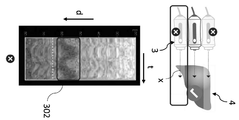
도 1 및 도 2에 도시된 바와 같이, TM-그래프는 프로브 (3) 위치 선정에 관한 유용한 정보를 제공할 수 있다. 실제로, 프로브 축 (x)이 간 (4)의 두꺼운 동종 부분과 정렬될 때, TM-그래프 (402)는 일반적으로 얇은 수평 시트의 스택처럼 보이고, 도 4에 도시된 바와 같이 수평 및 수직 둘 다로 동종 양태를 가진다. 대조적으로, 프로브 축 (x)이 간 (4)의 에지에 가까이 있을 때, TM-모드 그래프 (202, 302)는 종종 수평 (도 2) 또는 수직 (도 3)의 불연속적인 양태를 가진다.As shown in Figs. 1 and 2, the TM-graph can provide useful information regarding the positioning of the probe (3). In fact, when the probe axis (x) is aligned with the thick homogeneous portion of the liver (4), the TM-
여전하게, TM-그래프를 기반으로 하여 프로브를 적절하게 위치시킴은 상당한 어려움이 있고 오퍼레이터의 적당한 트레이닝을 필요로 한다. 더욱이, 통상의 기술자가 인식될 바와 같이, 부적절한 프로브 위치 선정은 부적절한 측정 및 환자 상태의 부정확한 진단으로 이어질 수 있다.Still, proper positioning of the probe based on the TM-graph is quite difficult and requires adequate training of the operator. Moreover, as one of ordinary skill in the art will appreciate, improper probe positioning can lead to improper measurement and inaccurate diagnosis of the patient condition.
TM-모드 또는 A-모드 그래프에 디스플레이된 초음파 신호는 프로브 위치에 관한 일부 정보를 제공하지만 전단파 전파를 예측하지는 않는다. 일부 상황에서는 이들 그래프가, 조건이 순간적 탄성영상 측정에 적합한 것처럼 적절하게 보일 수 있지만, 실제로 어떠한 전단파도 전파될 수 없다. 이는 액체 개재 (도 6의 TM-모드 그래프 (602) 참조), 공기 개재 (도 6의 TM-모드 그래프 (602') 참조), 좁은 늑간 공간 등이 있을 때 발생할 수 있다. 더욱이, 초음파 신호가 등에코 (isoechoic)이기 때문에 초음파 신호 상에서 혈관이 관찰되지 않을 수 있지만, 전단파 전파를 방해할 수 있다. 도 6은 혈관이 보이지 않는 채로 있는 등에코 혈관이 있을 때 획득된 TM-모드 그래프 (602''')를 도시한다 (이 혈관의 위치는 화살표로 식별됨).The ultrasound signal displayed in the TM-mode or A-mode graph provides some information about the probe position but does not predict shear wave propagation. In some situations these graphs may seem appropriate, as the conditions are suitable for instantaneous elastic image measurements, but in reality no shear wave can propagate. This can occur when there is a liquid inclusion (see TM-
초음파 및 탄성이 동일한 조건에 민감하지 않음에 따라, 초음파 데이터를 사용한 안내는 전단파의 전파를 예측할 수 없기 때문에 충분하지 않는다. 우수한 초음파 신호는 우수한 전단파 전파를 항상 초래하지는 않는다. 전단파 전파에 영향을 미치는 일부 요소는 초음파 전파에 영향을 미치지 않는다. 이는 혈관, 낭종, 입자가 있는 액체, 뻣뻣하거나 부드러운 종양 등이 될 수 있는 등에코 부분의 경우이다.As ultrasound and elasticity are not sensitive to the same conditions, guidance using ultrasound data is not sufficient because propagation of shear waves cannot be predicted. A good ultrasonic signal does not always result in good shear wave propagation. Some factors affecting shear wave propagation do not affect ultrasonic propagation. This is the case in the back of the nose, which can be blood vessels, cysts, fluid with particles, or a stiff or soft tumor.
종래의 TM-그래프 안내의 제한으로 인해, 오퍼레이터는 일반적으로 프로브를 위치시키려는 첫 번째 시도에서 적절한 프로브 위치를 찾지 못한다. 실제로, 오퍼레이터가 종종, 적절한 위치를 찾고 간 경직성을 특성화하기에 적당한 탄성파 전파 이미지를 기록하기 전에, 시행 착오로 상이한 위치를 테스트하면서 순간적인 탄성영상 측정을 여러 번 트리거해야 하는 것으로 나타났다. 이는 순간적인 탄성영상 측정을 트리거하기 전에 오퍼레이터가 프로브를 여전하게 그리고 단단하게 고정해야 하는 시간이 많이 소요된다. 통상의 기술자가 인식될 바와 같이, 그러한 시도는 오퍼레이터가 측정을 수행할 때마다 환자가 작은 기계적 펀치를 받음에 따라 검사 중인 환자에게 불쾌감을 줄 수 있다. 게다가, 그러한 시도는 오퍼레이터가 적절한 위치를 찾는 것을 방해하여, 이로써 작업 실패율을 증가시킬 수 있다.Due to the limitations of conventional TM-graph guidance, operators generally do not find a suitable probe position in the first attempt to position the probe. In fact, it has been shown that operators often have to trigger instantaneous elastic image measurements several times while testing different locations by trial and error, before finding a suitable location and recording a suitable seismic propagation image to characterize liver stiffness. This takes a lot of time for the operator to still and firmly fix the probe before triggering the momentary elastic image measurement. As one of ordinary skill in the art will appreciate, such an attempt can be offensive to the patient under examination as the patient receives a small mechanical punch each time the operator performs a measurement. In addition, such attempts can prevent the operator from finding a suitable location, thereby increasing the job failure rate.
이로써, 이러한 조직의 점탄성 속성의 정확한 특성화에 적합하고 상술된 FIBROSCAN® 시스템과 비교하여 개선된 안내 능력을 가진, 조직 특성화 시스템을 개발하는 것이 바람직하다.Thereby, it is desirable to develop a tissue characterization system, suitable for the precise characterization of the viscoelastic properties of such tissues and with improved guiding capabilities compared to the FIBROSCAN® system described above.
상기의 언급된 문제점 중 적어도 일부를 해결하기 위해, 개시된 기술은 피험자 또는 환자에서 동종 조직을 식별하는 시스템에 관한 것이다. 동종 조직의 구역을 검출할 시, 오퍼레이터는 조직 경직성 측정 및/또는 초음파 파라미터 결정을 개시할 수 있다.In order to address at least some of the above mentioned problems, the disclosed technology relates to a system for identifying allogeneic tissue in a subject or patient. Upon detecting an area of the allogeneic tissue, the operator may initiate measurement of tissue stiffness and/or determination of ultrasound parameters.
일부 실시예에서, 시스템은:In some embodiments, the system:
피험자의 신체에 고정되고 피험자의 조직에 기계 진동을 전달하는 진동기를 포함하는 프로브;A probe fixed to the subject's body and including a vibrator for transmitting mechanical vibration to the subject's tissue;
한 시퀀스의 초음파 샷을 방출하도록 구성된 초음파 방출기 및 대응하는 에코 신호를 수신하도록 구성된 초음파 수신기; 및An ultrasonic emitter configured to emit a sequence of ultrasonic shots and an ultrasonic receiver configured to receive a corresponding echo signal; And
상기 시스템이 다음 단계를 실행하도록 프로그래밍된 제어 모듈;을 포함하며,And a control module programmed to cause the system to execute the next step,
a) 피험자의 조직에 연속적이고 주기적인 기계 진동을 전달하는 단계 - 상기 주기적 기계 진동은 시간에 따라 여러 번 연속적으로 반복된 동일한 진동 패턴을 포함함; a) delivering continuous and periodic mechanical vibrations to the tissue of the subject, the periodic mechanical vibrations comprising the same vibration pattern repeated several times in succession over time;
b) 초음파 방출기에 의해 한 시퀀스의 초음파 샷을 방출하고 초음파 수신기에 의해 수신된 대응하는 에코 신호를 획득하여 조직으로 전달된 주기적 기계 진동에 의해 상기 조직이 움직이는 법을 축적하는 단계; b) emitting a sequence of ultrasonic shots by an ultrasonic emitter, acquiring a corresponding echo signal received by an ultrasonic receiver, and accumulating a method of moving the tissue by periodic mechanical vibrations transmitted to the tissue;
c) 상기 시스템의 오퍼레이터에게 동종성 정보를 제공하는 단계 - 상기 동종성 정보는 단계 b)에서 획득된 에코 신호 중 적어도 일부로부터 결정되며, 상기 동종성 정보는 조직이 탄성파를 전송하는 능력 및 탄성파의 전파에 대한 조직의 동종성을 나타냄. c) providing homogeneity information to the operator of the system-the homogeneity information is determined from at least some of the echo signals obtained in step b), and the homogeneity information is the ability of the tissue to transmit the acoustic wave and the Denotes the homogeneity of an organization for propagation.
상기 제어 모듈은 단계 b) 및 c)가 상기 시스템에 의해 계속하여 여러 번 연속적으로 실행되도록 프로그래밍된다.The control module is programmed such that steps b) and c) are continuously executed by the system several times in succession.
주기적 기계 진동이 조직을 통해 이동하는 법을 추적하여 얻어진 동종성 정보는 오퍼레이터가 특성화될 장기의 두꺼운 동종 부분 앞에 위치된 적절한 프로브 위치를 빠르고 쉽게 찾을 수 있도록 도와주는 매우 효율적인 안내 정보를 구성한다.Homogeneity information obtained by tracing how periodic mechanical vibrations travel through the tissue constitutes a highly efficient guidance information that helps the operator quickly and easily locate the appropriate probe positioned in front of the thick homologous portion of the organ to be characterized.
인식할 바와 같이, Mellema 등 (또는 예를 들어, Scientific Reports, volume 8, article number 17888, 2018에 발행된 H. Tzschatzsch의 "In vivo time-harmonic ultrasound elastography of the human brain detects acute cerebral stiffness changes induced by intracranial pressure variations" 문헌)에 기술된 것과 같은 2-차원 탄성파 속도 맵은 탄성파를 전파하는 조직의 능력 및 탄성파의 전파에 대한 조직의 동종성을 나타내는 동종성 정보를 구성하지 않는다. 실제로, 그러한 맵은 파동 전파에 관한 정보를 제공하지 않는데, 이는 이들 맵이 단지 검사 중인 장기의 순간 스냅샷만을 나타내기 때문이다.As will be appreciated, the "In vivo time-harmonic ultrasound elastography of the human brain detects acute cerebral stiffness changes induced by H. Tzschatzsch, published by Mellema et al. Two-dimensional seismic velocity maps such as those described in the document "intracranial pressure variations") do not constitute homogeneity information representing the tissue's ability to propagate seismic waves and its homogeneity to the propagation of seismic waves. In fact, such maps do not provide information about wave propagation, as these maps only represent instantaneous snapshots of the organ under examination.
개시된 기술에 따른 실시예에서, 상기 시스템에 의해 제공된 동종성 정보는 상기에서 언급된 주기적 기계 진동에 의해 야기되는 조직의 변형의 시공간 특성이 동종 매체에서 이동하는 파동의 것인지를 나타낸다 (단계 b에서 획득된 에코 신호에 의해 해당 변형이 추적됨)In an embodiment according to the disclosed technology, the homogeneity information provided by the system indicates whether the spatiotemporal characteristic of the deformation of the tissue caused by the periodic mechanical vibration mentioned above is that of a wave traveling in the homogeneous medium (obtained in step b). The corresponding transformation is tracked by the generated echo signal)
도 14, 16, 17 및 18에 도시된 바와 같이, 조직을 통한 탄성파의 전파에 대한 조직 변형의 시공간 특성, 즉 시간의 함수로서 및 적어도 하나의 공간 좌표의 함수로서 이러한 변형의 변화를 둘 다 나타내는 특성 (이로써 실제로 탄성파가 전파되는 방식을 나타냄)은 조직의 다소 동종 성질을 매우 간단하고 파악하기 쉬운 방식으로 드러낸다. 그러한 시공간 특성은, 예를 들어, 조직의 주기적 변형의 위상 지연의 깊이에 대한 변화를 나타내는 데이터를 포함할 수 있다. 도 14에 도시된 바와 같이, 이 위상 지연은 조직이 동종일 때 깊이에 따라 실질적으로 선형으로 변하며, 이는 오퍼레이터가 식별하기 쉽다. 상기 언급된 시공간 특성은 또한 깊이 (d)의 함수로서 및 시간 (t)의 함수로서 조직의 변형을 둘 다 나타내는 데이터를 포함할 수 있다. 도 16 및 18 (그래프 188a)에 도시된 바와 같이, 깊이의 함수로서 및 시간의 함수로서 조직의 변형을 나타내는 그래프는 대각선, 실질적으로 선형인 스트라이프를 포함하며, 이는 조직이 동종일 때 오퍼레이터에 의해 쉽게 식별될 수 있다.14, 16, 17 and 18, the spatio-temporal properties of tissue deformation for propagation of elastic waves through the tissue, i.e., both as a function of time and as a function of at least one spatial coordinate. The characteristics (and thus the way the seismic waves actually propagate) reveal the somewhat homogeneous nature of the tissue in a very simple and easy-to-understand way. Such spatio-temporal properties may include data indicative of a change in the depth of the phase delay of a periodic deformation of the tissue, for example. As shown in Fig. 14, this phase delay changes substantially linearly with depth when the tissue is homogeneous, which is easy for the operator to discern. The above-mentioned spatiotemporal properties may also include data representing both the deformation of the tissue as a function of depth (d) and as a function of time (t). As shown in Figures 16 and 18 (
그러한 주기적 탄성파가 전파되는 방식은 도 18에 도시된 바와 같이, TM-모드 그래프보다 조직의 구조 및 그 탄성 속성에 매우 더 민감하다.The manner in which such periodic acoustic waves propagate is much more sensitive to the structure of the tissue and its elastic properties than the TM-mode graph, as shown in FIG. 18.
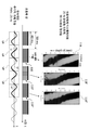
도 18의 표의 마지막 3 개의 열은 3 개의 상이한 상황에 대해 TM-모드 그래프 (182c, 182d, 182e), 주기적 모드 (주기적 탄성파 전파 그래프)에서 획득된 탄성파 전파 이미지 (188c, 188d, 188e) 및 순간적 모드 (185c, 185d, 185e)에서 획득된 탄성파 전파 이미지를 보여주고, 하나는 간의 에지에 가까운 프로브 위치 (열 c)에 해당하고, 다른 두 개는 액체 (열 d) 또는 공기 개재 (열 e)를 갖는 상황이다. 도 18에서 볼 수 있는 바와 같이, 이러한 상황에서, TM-모드 그래프는 상기 상황이 (열 a와 같이) 순간적 탄성영상 측정에 적당한 것처럼 보이지만, 실제로는 그렇지 않는다 (순간적 탄성영상 이미지 (185c, 185d, 185e) 참고). 다시 말하면, TM-모드 이미징은, 프로브가 간의 에지에 가까이 위치하는지 여부 또는 프로브와 타겟 장기 사이에 개재된 공기 또는 액체가 있는지 여부를 정확하게 검출할 수 없기 때문에, 적당한 프로브 위치 선정과 부적당한 프로브 위치 선정 사이를 구별하지 않는다. 두드러지게 대조적으로, 잡음이 있는 주기적인 탄성파 전파 이미지 (188c, 188d, 188e)는 매끄러운 (실질적으로 선형) 에지를 갖는 하나 또는 여러 개의 대각선 스트라이프와 달리 수많은 불규칙한 단편을 포함한다. 이로써, 주기적인 탄성파 전파 이미지 (188c, 188d, 188e)는 순간적 탄성영상 측정에 적절한 프로브 위치 선정을 즉시 보여준다. 더욱이, 초음파 신호에 보이지 않는 작고 등에코 (isoechoic)인 혈관의 존재 (도 18의 그래프 182b 참조)는 주기적 모드에서 획득된 탄성파 전파 이미지에서 쉽게 검출될 수 있다 (도 18의 그래프 188b 참조).The last three columns of the table in Fig. 18 are TM-mode graphs (182c, 182d, 182e), seismic propagation images (188c, 188d, 188e) acquired in periodic mode (periodic seismic propagation graph) and instantaneous Shows the seismic propagation images acquired in modes (185c, 185d, 185e), one corresponding to the probe position close to the edge of the liver (column c), and the other two liquid (column d) or air intercalation (column e) It is a situation to have. As can be seen in Fig. 18, in this situation, the TM-mode graph appears to be suitable for instantaneous elastic image measurement (such as column a), but in reality it is not (temporal
통상의 기술자가 인식되는 바와 같이, 도 18의 이미지 (188a)와 같이, 실질적으로 균일하고 그리고/또는 매끄러운 에지를 갖는 대각선 스트라이프를 갖는 주기적인 탄성파 전파 이미지는 프로브가 적당하게 위치되고 상황이 순간적 탄성영상 측정 (도 18의 순간적인 탄성파 전파 이미지 (185a) 참조)에 적절하다는 것을 즉시 나타낸다.As one of ordinary skill in the art will appreciate, a periodic acoustic wave propagation image having a diagonal stripe with a substantially uniform and/or smooth edge, such as
발견된 바와 같이, 실제로, 연속적으로 갱신되어 오퍼레이터에게 제공된 동종성 정보는 더 자주 오퍼레이터, 심지어 훈련되지 않은 자라도 처음에 적당한 프로프 위치를 올바르게 찾을 수 있도록 한다.As has been found, in fact, the homogeneity information that is continuously updated and provided to the operator more often allows the operator, even an untrained one, to correctly find a suitable profile position in the first place.
게다가, 검사 중 피험자에게 전달되는 주기적 기계 진동은, 오퍼레이터 (그/그녀)가 적당한 프로브 위치를 찾을 때까지, 오퍼레이터에 의해 반복적으로 트리거되는 짧고 순간적인 기계적 펄스보다 피험자에게 덜 불쾌감을 주고, 주기적인 탄성파 모니터링에 요구된 진동 진폭 이상의 모든 것은 순간적 탄성영상 측정을 달성하기에 요구된 것보다 현저하게 작다. 부가적으로, 오퍼레이터를 안내하기 위해 개시된 기술의 시스템에 사용된 기계적 여기의 연속적인 성질은 연속적인 안내를 가능하게 한다.In addition, the periodic mechanical vibrations transmitted to the subject during the examination are less unpleasant to the subject than the short, instantaneous mechanical pulses repeatedly triggered by the operator until the operator (he/she) finds a suitable probe position. Anything above the vibration amplitude required for seismic monitoring is significantly smaller than that required to achieve instantaneous seismic measurements. Additionally, the continuous nature of mechanical excitation used in the system of the disclosed technology to guide the operator enables continuous guidance.
피험자에게 전달되는 주기적 기계 진동으로 인해 야기된 변형의 시공간 모니터링은 2D 또는 3D 이미징 능력이 없는 단일-빔 (단일 트랜스듀서) 초음파 시스템을 사용하여 달성될 수 있다. 실제로, 시공간 관점으로부터 파동의 전파를 모니터링함은 시간의 함수로서 및 단지 하나의 공간 차수 (즉, 깊이)의 함수로서 조직 변형을 모니터링함으로써 달성될 수 있다. 다시 말하면, 시공간 모니터링은, 둘 다의 공간 차수 (Mellema 등에서와 같이 깊이 및 측 방향 이동)인 2 개의 샘플링 차수를 사용하는 대신, 한 차수는 시간이고 다른 것은 깊이인 2 차원 샘플링의 변형을 사용하여 수행될 수 있다. 통상의 기술자가 인식되는 바와 같이, 2D 이미징 초음파 시스템 대신에, 단일 빔 초음파 시스템을 사용함은 공간적 관점으로부터 단일 차원인, 획득된 에코 신호를 신속하게 프로세싱할 수 있다. 이는 조직의 탄성 변형이 추적되는 시간적 샘플링률을 증가시키는 것을 허용한다. 이로써, 조직의 탄성 변형은 종래 기술에서의 고조파 탄성영상 방법보다 높은 시간적 해상도로 모니터링된다.Spatiotemporal monitoring of the deformation caused by periodic mechanical vibrations delivered to the subject can be achieved using a single-beam (single transducer) ultrasound system without 2D or 3D imaging capabilities. In practice, monitoring the propagation of waves from a spatiotemporal perspective can be achieved by monitoring tissue deformation as a function of time and only as a function of one spatial order (ie, depth). In other words, instead of using two sampling orders, which are both spatial orders (depth and lateral shifts as in Mellema et al.), instead of using a variant of two-dimensional sampling, one order is time and the other is depth. Can be done. As one of ordinary skill in the art will appreciate, using a single beam ultrasound system instead of a 2D imaging ultrasound system can quickly process the acquired echo signal, which is a single dimension from a spatial point of view. This allows to increase the temporal sampling rate at which the elastic deformation of the tissue is tracked. Thereby, the elastic deformation of the tissue is monitored with a higher temporal resolution than the harmonic acoustic imaging method in the prior art.
게다가, 높은 시간적 샘플링률은 조직의 주기적인 변형의 동일한 기간, 또는 동일한 기간의 적어도 주요 부분을, 한꺼번에, 전체적으로 샘플링할 수 있다. 이는, 조직의 주기적인 변형이 작은 부분에 의해 샘플링되고, 기간의 작은 부분 (예를 들어 단일 순간)을 샘플링한 다음 차후 기간 등의 작은 부분을 샘플링하여, 전체 진동 기간 (도 13의 전파 이미지 (130)와 같음)을 보여주는 이미지를 사후적으로 재구성하는 스트로보스코프 유사 기술과 비교할 때 매우 흥미롭다. 실제로, 스트로보스코프 기술로, 전체 진동 기간을 보여주는 완전히 갱신된 새로운 이미지를 얻는데 필요한 지연 시간은 동일한 기간이 높은 샘플링률로 한꺼번에 모두 샘플링될 때보다 매우 길다 (도 13의 예에서, 지연 시간은 동일한 기간이 한꺼번에 모두 샘플링될 때보다 대략적으로 4배 더 길다). 보다 중요한 것은, 스트로보스코프 샘플링으로 얻어진 시간적 이미지는 스퓨리어스 효과 (spurious effects) 및 노이즈에 의해, 특히 호흡에 의해 야기된 조직 변위 또는 프로브의 약간의 변위로 인해 종종 손상된다. 더욱이, 스트로보스코프 샘플링에 의해 얻어진 전파 이미지의 시간적 해상도는 일반적으로 동일한 기간이 한꺼번에 모두 샘플링될 때보다 작다 (예를 들어, 도 13의 전파 이미지 (131 내지 134)의 시간적 해상도는 전파 이미지 (130)의 시간적 해상도보다 우수하다).In addition, a high temporal sampling rate can sample the same period of periodic transformation of the tissue, or at least a major portion of the same period, all at once. This means that the periodic deformation of the tissue is sampled by a small portion, a small portion of the period (e.g., a single moment) is sampled, and then a small portion of the subsequent period, etc. 130)), which is very interesting when compared to a stroboscope-like technique that reconstructs the image post-hoc. In fact, with the stroboscope technique, the delay time required to obtain a completely updated new image showing the entire oscillation period is much longer than when the same period is sampled all at once at a high sampling rate (in the example of Fig. 13, the delay time is the same period. Is roughly 4 times longer than when all sampled at once). More importantly, the temporal images obtained with stroboscope sampling are often damaged by spurious effects and noise, especially due to tissue displacement caused by respiration or slight displacement of the probe. Moreover, the temporal resolution of the radio wave image obtained by stroboscope sampling is generally smaller than when the same period is all sampled at once (e.g., the temporal resolution of the
통상의 기술자가 인식되는 바와 같이, 깊이 및 시간의 함수로서 (도 18의 것과 같은) 시공간적 방식으로 조직의 주기적인 변형을 보여주는 그래프는 있는 그대로 이해하기 쉽다. 이는, (2 개의 공간 좌표의 함수로서) 조직의 순간 변형을 나타내는 그래프가 거의 이해하기 힘들고 (예를 들어, Millena 등의 도 9a, 또는 Tzschatzsch 등의 도 3a 참조), (2D 전단파 속도 맵과 같은) 오퍼레이터에게 유용한 정보를 얻기 위해 복잡한 후-프로세싱을 요구하는 Mellema 등 또는 Tzschatzsch 등의 것과 같은 종래 기술의 고조파 탄성영상 기술과 비교할 때 상당하게 놀라웠다.As one of ordinary skill in the art will appreciate, graphs showing periodic deformation of tissue in a spatiotemporal manner (such as that of FIG. 18) as a function of depth and time are easy to understand as is. This means that graphs representing instantaneous deformations of tissue (as a function of two spatial coordinates) are hardly understandable (see, for example, Fig. 9A of Millena et al., or Fig. 3A of Tzschatzsch et al.), (such as a 2D shear wave velocity map). ) Compared to prior art harmonic acoustic imaging techniques such as Mellema et al. or Tzschatzsch et al., which require complex post-processing to obtain useful information to the operator, it was quite surprising.
요약하면, 개시된 기술에 따라 조직을 특성화하는 시스템은 매우 우수한 안내 능력을 가지며, 오퍼레이터가 동종 조직의 구역을 신속하고 쉽게 찾을 수 있게 하고, 순간적 탄성영상 측정에 적절하거나, 조직 내의 초음파 파동 전파에 대한 초음파 파라미터를 결정할 수 있게 한다.In summary, the system for characterizing tissues according to the disclosed technology has very good guiding capabilities, allows the operator to quickly and easily find areas of the homogeneous tissue, is suitable for instantaneous elastic imaging measurements, or for ultrasonic wave propagation within tissues. Allows determination of ultrasonic parameters.
이들 안내 능력으로부터의 이점을 얻기 위해, 개시된 기술에 따라 조직을 특성화하는 시스템의 실시예에서, 시스템의 제어 모듈은 다음 중 하나를 포함하는 조직의 적어도 하나의 물리적인 속성을 결정하도록 추가로 프로그래밍된다:To benefit from these guiding capabilities, in embodiments of systems that characterize tissue according to the disclosed techniques, the control module of the system is further programmed to determine at least one physical property of the tissue, including one of the following: :
조직 감쇠 값 내의 초음파 파동 전파에 대한 초음파 파라미터;Ultrasonic parameters for ultrasonic wave propagation within the tissue attenuation value;
순간적 탄성영상에 의해 결정된 전단파 전파에 관련된 조직의 기계적 속성.Mechanical properties of tissue related to shear wave propagation determined by instantaneous elastic imaging.
초음파 파라미터는 브로드밴드 초음파 감쇠 (Broadband Ultrasound Attenuation, BUA, 보통 dB/cm/MHz 단위로 표시), 특정 주파수에서 측정된 감쇠 (dB/cm) 단위로 표시), 또는 제어 감쇠 파라미터 (Controlled Attenuation Parameter, CAP)와 같은, 조직에서 초음파 감쇠를 반영하는 초음파 감쇠 파라미터를 포함한다. 그러나, 이는 부가적인 파라미터가 다른 실시예에서 결정될 수 있기 때문에 제한되지 않는다.Ultrasound parameters are either Broadband Ultrasound Attenuation (BUA, usually expressed in dB/cm/MHz), attenuation measured at a specific frequency (dB/cm), or Controlled Attenuation Parameter (CAP). ), including ultrasonic attenuation parameters that reflect ultrasonic attenuation in the tissue. However, this is not limited as additional parameters may be determined in other embodiments.
전단파 전파와 관련된 조직의 기계적 속성은 전단파의 전파 속도 (Vs), 조직의 전단 모듈러스 또는 조직의 영률 (E)과 같은 조직 경직성에 관련된 양일 수 있다. 이는 점도와 같이 조직에서 저 주파수 전단파 감쇠에 관련된 양일 수도 있다.The mechanical properties of the tissue associated with shear wave propagation may be quantities related to tissue stiffness, such as the propagation velocity of the shear wave (V s ), the shear modulus of the tissue, or the Young's modulus of the tissue (E). This may be a quantity related to the attenuation of low frequency shear waves in the tissue, such as viscosity.
인식되는 바와 같이, 주기적 탄성파의 전파가 동종 조직을 찾기 위해 예비 모니터링되는, 순간적 탄성영상에 의해 기계적 속성을 결정하는 시스템은 어떻게든 순간적 탄성영상을 위해 초기에 구성되며, 그리고 매우 상이하고, 심지어 순간적 탄성영상 기술 (압축파 및 전단파를 분리하는 것을 목표로 함) 및 종래 기술의 고조파 탄성영상 기술 (변형 분야의 거의 순수한 공간적 특징에 중점을 두고 있고, 오퍼레이터가 프로브를 적당하게 위치시키는데 도움을 주는 것을 목표로 하고 있지 않음)과는 상반되는, 상기에서 제시된 안내 기술을 구현하도록 추가 변형된 시스템이다.As will be appreciated, the system for determining the mechanical properties by instantaneous elastic imaging, in which the propagation of periodic seismic waves is preliminarily monitored to find homogeneous tissue, is somehow initially configured for instantaneous elastic imaging, and very different, even instantaneous. Seismic imaging technology (which aims to separate compressed and shear waves) and harmonic seismic imaging technology of the prior art (focusing on the almost pure spatial characteristics of the deformation field, helping the operator to properly position the probe) It is a further modified system to implement the guidance technology presented above, as opposed to).
개시된 기술에 따른 실시예에서, 제어 모듈은 단계 b)에서 획득된 에코 신호 중 적어도 일부로부터, 조직 내의 상이한 깊이에서, 그리고 조직에 전달되는 주기적 기계 진동의 상이한 순간에서, 조직의 주기적인 변형을 나타내는 데이터를 결정하도록 프로그래밍된다.In an embodiment according to the disclosed technology, the control module exhibits periodic deformation of the tissue from at least some of the echo signals obtained in step b), at different depths within the tissue, and at different moments of periodic mechanical vibrations transmitted to the tissue. It is programmed to determine the data.
개시된 기술에 따른 실시예에서, 동종성 정보는 다음 중 하나를 포함한다:In an embodiment according to the disclosed technology, the homogeneity information includes one of the following:
조직의 변형의 시간적, 주기적 변화의 적어도 하나의 시간적 특성의 깊이에 걸친 변화를 나타내는 그래프; 또는A graph showing a change over the depth of at least one temporal characteristic of a temporal, periodic change of tissue deformation; or
조직이 주어진 깊이 범위에 걸쳐 동종인 것처럼 상기 특성이 깊이에 따라 변화되는지 여부를 명시하는 표시.An indication specifying whether the characteristic changes with depth as if the tissue was homogeneous over a given depth range.
그래프는 다음을 표시할 수 있다:The graph can display:
- 깊이의 함수로서 시간에 따른 변형의 변화;-Change in deformation over time as a function of depth;
- 깊이의 함수로서 조직의 주기적인 변형의 위상 지연;-Phase delay of periodic deformation of tissue as a function of depth;
- 깊이의 함수로서 이러한 주기적인 변형의 엔벨로프의 진폭.-The amplitude of the envelope of this periodic deformation as a function of depth.
실시예에서, 상기에서 언급된 그래프는 조직 내의 상이한 깊이에서 그리고 조직에 전달되는 주기적 기계 진동의 상이한 순간에서 조직의 변형을 나타내고, 상기 그래프는 픽셀 행 인덱스가 깊이를 나타내고 픽셀 열 인덱스가 시간을 나타내거나 그 반대로 수행되는 2 차원 이미지이고, 각 픽셀은 고려되는 픽셀과 연관된 깊이 및 시간에서 조직의 변형을 나타내는 픽셀 값을 가진다.In an embodiment, the above-mentioned graph represents the deformation of the tissue at different depths within the tissue and at different moments of cyclic mechanical vibration transmitted to the tissue, wherein the graph shows the pixel row index represents the depth and the pixel column index represents the time. A two-dimensional image performed or vice versa, with each pixel having a pixel value representing the deformation of the tissue in depth and time associated with the pixel being considered.
실시예에서, 상기에서 언급된 표시는, 조직 내의 상이한 깊이에서, 그리고 조직에 전달되는 주기적 기계 진동의 상이한 순간에서 조직의 변형을 나타내는 그래프 (상기 그래프는 픽셀 행 인덱스가 깊이를 나타내고 픽셀 열 인덱스가 시간을 나타내거나 그 반대로 수행되는 2 차원 이미지이고, 각 픽셀은 고려되는 픽셀과 연관된 깊이 및 시간에서 조직의 변형을 나타내는 픽셀 값을 가짐)가 상기 깊이 범위에 걸쳐 대각선 스트라이프로 구성되는지 여부를 명시한다.In an embodiment, the above-mentioned indication is a graph representing the deformation of the tissue at different depths within the tissue, and at different moments of cyclic mechanical vibration transmitted to the tissue, where the pixel row index represents the depth and the pixel column index is It is a two-dimensional image that represents time and vice versa, and specifies whether each pixel has a pixel value representing the deformation of the tissue in depth and time associated with the pixel being considered) is composed of diagonal stripes across the depth range. .
실시예에서, 시스템은 오퍼레이터가 주기적 기계 진동의 진폭을 수동적으로 조정할 수 있게 하는, 커서, 슬라이더, 버튼 또는 노브 (knob)와 같은 수동 조정 제어부를 포함한다. 이는 조직에 전달되는 주기적 기계 진동으로 인해 야기된 조직의 주기적 변형 진폭이 너무 낮거나 너무 높은 경우에 유용하다. 시스템은 조직의 주기적인 변형의 진폭에 관한 정보를 오퍼레이터에게 디스플레이하기 위한 진폭 표시기를 포함할 수 있다.In embodiments, the system includes manual adjustment controls, such as cursors, sliders, buttons or knobs, that allow the operator to manually adjust the amplitude of periodic mechanical vibrations. This is useful when the amplitude of periodic deformation of the tissue caused by periodic mechanical vibration transmitted to the tissue is too low or too high. The system may include an amplitude indicator for displaying information to the operator regarding the amplitude of periodic deformation of the tissue.
실시예에서, 시스템은 조직의 결과적인 주기적 변형의 진폭을 기반으로 하여 주기적 기계 진동의 진폭을 자동으로 (즉, 오퍼레이터의 행동을 요구하지 않고) 조정하도록 구성된다. 보다 정확하게는, 시스템은, 조직의 결과적인 주기적 변형의 진폭이 너무 낮을 때 (주어진 임계치보다 낮을 때) 주기적 기계 진동의 진폭을 증가시키고, 조직의 결과적인 주기적 변형의 진폭이 너무 높을 때 (또 다른 진폭 임계치를 초과할 때) 주기적 기계 진동의 진폭을 감소시키도록 구성될 수 있다.In an embodiment, the system is configured to automatically adjust (ie, without requiring operator action) the amplitude of periodic mechanical vibrations based on the amplitude of the resulting periodic deformation of the tissue. More precisely, the system increases the amplitude of periodic mechanical vibrations when the amplitude of the resulting cyclical deformation of the tissue is too low (below a given threshold), and when the amplitude of the resulting cyclical deformation of the tissue is too high (another When the amplitude threshold is exceeded) it may be configured to reduce the amplitude of periodic mechanical vibrations.
실시예에서, 시스템은 주기적 기계 진동에 대해 선택된 진폭을 기반으로 하여, 순간적 탄성영상에 의한 전단파 전파와 관련된 조직의 기계적 속성을 측정하기 위해 피험자에게 전달된 순간적인 기계적 펄스의 진폭을 조정하도록 구성된다. 이 경우는 주기적 탄성영상에 의한 조직의 예비 특성이 상기에서 제시된 상이한 이점에 더하여, 차후 순간적 탄성영상 측정을 수행하기에 적합한 순간적인 기계적 펄스의 진폭을 결정할 수 있게 한다.In an embodiment, the system is configured to adjust the amplitude of the instantaneous mechanical pulse delivered to the subject to measure the mechanical properties of the tissue associated with shear wave propagation by instantaneous elastic imaging, based on the amplitude selected for the periodic mechanical vibration. . In this case, in addition to the different advantages presented above, the preliminary characteristics of the tissue by the periodic elastic imaging makes it possible to determine the amplitude of the instantaneous mechanical pulse suitable for performing the subsequent instantaneous elastic imaging measurement.
인식되는 바와 같이, 개시된 기술에 따라서, 상기에서 제시된 상이한 실시예는 모든 기술적으로 가능한 조합에 따라 함께 결합될 수 있다.As will be appreciated, in accordance with the disclosed technology, the different embodiments presented above may be combined together in all technically possible combinations.
옵션으로, 상기에서 제시된 조직을 특성화하는 시스템의 비제한적인 특징은 제출된 바와 같이, 청구항 3 내지 7 및 10 내지 18에 의해, 개시된 기술에 따라 정의된다.Optionally, the non-limiting features of the system characterizing the tissue presented above are defined according to the disclosed technology, by claims 3-7 and 10-18, as submitted.
개시된 기술은 또한 다음을 포함하는 시스템에 의해 수행되는 조직 특성화 방법을 제공한다:The disclosed technology also provides a method of tissue characterization performed by a system comprising:
피험자의 피부에 고정되고 피험자의 조직에 기계 진동을 전달하는 진동기를 포함하는 프로브;A probe fixed to the subject's skin and including a vibrator for transmitting mechanical vibration to the subject's tissue;
한 시퀀스의 초음파 샷을 방출하도록 구성된 초음파 방출기 및 대응하는 에코 신호를 수신하도록 구성된 초음파 수신기; 및An ultrasonic emitter configured to emit a sequence of ultrasonic shots and an ultrasonic receiver configured to receive a corresponding echo signal; And
상기 시스템이 방법의 다음 단계를 실행하도록 프로그래밍된 제어 모듈A control module programmed to cause the system to execute the next step of the method
a) 피험자의 조직에 연속적이고 주기적인 기계 진동을 전달하는 단계 - 상기 주기적 기계 진동은 시간에 따라 여러 번 연속적으로 반복된 동일한 진동 패턴을 포함함; a) delivering continuous and periodic mechanical vibrations to the tissue of the subject, the periodic mechanical vibrations comprising the same vibration pattern repeated several times in succession over time;
b) 초음파 방출기에 의해 한 시퀀스의 초음파 샷을 방출하고 초음파 수신기에 의해 수신된 대응하는 에코 신호를 획득하여 조직으로 전달된 주기적 기계 진동에 의해 상기 조직이 움직이는 법을 추적하는 단계; b) emitting a sequence of ultrasonic shots by an ultrasonic emitter, acquiring a corresponding echo signal received by an ultrasonic receiver, and tracking how the tissue is moved by periodic mechanical vibrations transmitted to the tissue;
c) 상기 시스템의 오퍼레이터에게 동종성 정보를 제공하는 단계 - 상기 동종성 정보는 단계 b)에서 획득된 에코 신호 중 적어도 일부로부터 결정되며, 상기 동종성 정보는 조직이 탄성파를 전송하는 능력 및 탄성파의 전파에 대한 조직의 동종성을 나타냄; c) providing homogeneity information to the operator of the system-the homogeneity information is determined from at least some of the echo signals obtained in step b), and the homogeneity information is the ability of the tissue to transmit the acoustic wave and the Indicates organizational homogeneity to propagation;
상기 제어 모듈은 단계 b) 및 c)가 상기 시스템에 의해 계속하여 여러 번 연속적으로 실행되도록 프로그래밍된다. The control module is programmed such that steps b) and c) are continuously executed by the system several times in succession.
상술된 시스템의 상이한 실시예의 특징은 조직을 특성화하는 이러한 방법에도 적용될 수 있다.The features of the different embodiments of the systems described above can also be applied to this method of characterizing tissue.
도 1은 FIBROSCAN® 시스템의 디스플레이 스크린에 의해 오퍼레이터에게 디스플레이되는 상이한 그래프 및 표시기를 도시하고;
도 2 내지 4는 특성화될 장기에 대한 FIBROSCAN®의 프로브의 상이한 위치에 대해 오퍼레이터에게 디스플레이되는 상이한 TM-모드 그래프를 도시하고;
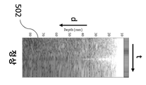
도 5는 FIBROSCAN®의 프로브가 잘 위치될 때 (이때 그의 축이 특성화될 장기 상의 중심에 위치됨) 획득된 TM-모드 그래프를 도시하고;
도 6은 프로브가 적당하게 위치되지 않을 (그의 축이 특성화될 장기의 에지에 가까이 있음), 또는 장기의 적당한 기계 특성화에 적합하지 않는 액체, 공기 또는 혈관 개재가 있는 상황에서 획득된 상이한 TM-모드 그래프를 도시하고;
도 7은 개시된 기술의 일부 실시예에 따른 조직 특성화 시스템의 블록도이고;
도 8은 개시된 기술의 일부 실시예에 따른 조직 특성화 방법의 흐름도이고;
도 9는 개시된 기술의 일부 실시예에 따라, 피험자의 조직에 전달되는 연속적이고 주기적인 기계 진동, 이 진동에 의해 야기된 조직의 변형을 추적하기 위해 방출된 초음파 샷의 시퀀스 및 이로부터 얻어진 탄성파 전파 이미지를 도시하고;
도 10은 개시된 기술의 일부 실시예에 따라, 피험자의 조직에 전달되는 연속적이고 주기적인 기계 진동, 및 이 진동에 의해 야기된 조직의 변형을 추적하기 위해 초음파 샷의 시퀀스를 방출하는 또 다른 방식을 도시하고;
도 11은 개시된 기술의 일부 실시예에 따라, 피험자의 조직에 전달되는 연속적이고 주기적인 기계 진동, 이 진동에 의해 야기된 조직의 변형을 추적하기 위해 초음파 샷의 시퀀스를 방출하는 여전히 또 다른 방식 및 이로부터 얻어진 주기적인 탄성파 전파 이미지를 도시하고;
도 12는 개시된 기술의 일부 실시예에 따라, 도 11의 주기적인 탄성파 전파 이미지가 오퍼레이터 시청을 위해 순간적으로 정렬될 수 있는 방법을 도시하고;
도 13은 개시된 기술의 일부 실시예에 따라, 조직의 주기적인 변형을 추적하기 위한 낮은 샘플링률, 스트로보스코프 유사 방법 (stroboscopic like method)과 그러한 조직의 주기적인 변형을 추적하는 높은 샘플링률 방법 사이의 차이점을 도시하되, 상기 차이점에서 조직 변형의 동일한 기간이 전체로서 한번에 모두 모니터링되는 것을 도시하고;
도 14는 개시된 기술의 일부 실시예에 따라, 조직의 특정 깊이에서 탄성파의 위상 지연이 결정되는 것을 도시하고;
도 15는 개시된 기술의 일부 실시예에 따라, 조직을 특성화하는 시스템에 의해 오퍼레이터에게 디스플레이되는 상이한 그래프 및 표시기를 도시하고;
도 16 및 17은 개시된 기술의 일부 실시예에 따라, 동종 및 비-동종 조직으로부터 예시적인 탄성파 전파 이미지 각각을 도시하며;
도 18은 개시된 기술의 일부 실시예에 따라, 오퍼레이터에게 제공되는 예시적인 TM-그래프, 주기적인 탄성파 전파 이미지 및 순간적인 탄성파 전파 이미지를 도시하며, 이들 그래프 및 이미지는 다수의 상이한 상황 및 프로브 위치에서 얻어진다.1 shows different graphs and indicators displayed to the operator by the display screen of the FIBROSCAN® system;
Figures 2-4 show different TM-mode graphs displayed to the operator for different positions of the probe of FIBROSCAN® relative to the organ to be characterized;
5 shows a TM-mode graph obtained when the probe of FIBROSCAN® is well positioned (where its axis is centered on the organ to be characterized);
Figure 6 shows different TMs obtained in situations in which the probe will not be properly positioned (its axis is close to the edge of the organ to be characterized), or in the presence of liquid, air or vascular intercalation that is not suitable for proper mechanical characterization of the organ. -Show the mode graph;
7 is a block diagram of a tissue characterization system in accordance with some embodiments of the disclosed technology;
8 is a flow diagram of a method for tissue characterization in accordance with some embodiments of the disclosed technology;
9 is a sequence of ultrasonic shots emitted to track continuous and periodic mechanical vibrations transmitted to a subject's tissues, tissue deformation caused by these vibrations, and acoustic wave propagation obtained therefrom, according to some embodiments of the disclosed technology. Shows the image;
10 illustrates another way of emitting a sequence of ultrasound shots to track continuous and periodic mechanical vibrations delivered to the subject's tissues, and the deformation of the tissues caused by these vibrations, in accordance with some embodiments of the disclosed technology. Show;
11 is a still another way of emitting a sequence of ultrasound shots to track continuous and periodic mechanical vibrations delivered to the subject's tissue, the deformation of the tissue caused by this vibration, in accordance with some embodiments of the disclosed technology, and It shows the periodic acoustic wave propagation image obtained therefrom;
12 illustrates how the periodic acoustic wave propagation image of FIG. 11 can be momentarily aligned for operator viewing, in accordance with some embodiments of the disclosed technology;
13 shows between a low sampling rate, stroboscopic like method for tracking periodic deformation of tissue and a high sampling rate method for tracking periodic deformation of such tissue, according to some embodiments of the disclosed technology. Showing differences, wherein the same period of tissue deformation in the differences is monitored all at once as a whole;
14 illustrates the determination of a phase delay of an acoustic wave at a specific depth of tissue, in accordance with some embodiments of the disclosed technology;
15 illustrates different graphs and indicators displayed to an operator by a system characterizing tissue, in accordance with some embodiments of the disclosed technology;
16 and 17 show exemplary seismic propagation images from homogeneous and non-homogeneous tissues, respectively, in accordance with some embodiments of the disclosed technology;
18 shows exemplary TM-graphs, periodic seismic propagation images, and instantaneous seismic propagation images provided to the operator, in accordance with some embodiments of the disclosed technology, these graphs and images in a number of different situations and probe locations. Is obtained.
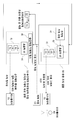
도 7은 동종 조직을 검출하도록 구성된, 조직 특성화 초음파 시스템 (1)의 블록도이다. 이 시스템 (1)은 다음을 포함한다:7 is a block diagram of a tissue characterizing
- 피험자 (50)의 신체에 대해 유지되고 피험자의 조직 (51)에 기계 진동을 전달하도록 구성된 진동기 (12)를 포함하는 프로브 (10);-A
- 한 시퀀스의 초음파 샷을 방출하도록 구성된 초음파 방출기, 및 해당 에코 신호를 수신하여 피험자의 조직이 그러한 기계 진동에 의해 어떻게 움직이는지 추적하도록 구성된 초음파 수신기;-An ultrasonic emitter configured to emit a sequence of ultrasonic shots, and an ultrasonic receiver configured to receive a corresponding echo signal to track how the subject's tissue is moved by such mechanical vibrations;
- 프로브 (10)를 제어하고 초음파 수신기에 의해 획득된 데이터를 프로세싱하는 제어 모듈 (20).-A
"조직"이라는 표현은 피험자 (50) (인간 또는 동물)의 신체 일부를 의미하는 것으로 이해된다. 이 표현이 반드시 전체 장기 또는 단일 장기를 지정하는 것은 아니다. 기계 진동이 전달되고 초음파 샷에 의해 조직 변형이 추적되는 조직 (51)은 프로브의 축 (z)을 따라, 프로브 (20) 부근에 위치한 피험자 신체의 일부이다.The expression “tissue” is understood to mean a body part of subject 50 (human or animal). This expression does not necessarily designate an entire organ or a single organ. The
시스템 (1)은 조직 (51)이 동종인지 여부 및 조직이 주기적 탄성영상 기술을 사용하여 탄성파, 특히 전단파를 전송할 수 있는지 여부를 나타내는 동종성 정보를 결정하고, 이러한 정보를 오퍼레이터 인터페이스 (30)에 의해 오퍼레이터에게 제공하도록 구성된다.The
동종성 정보는 오퍼레이터가 간 또는 비장과 같은, 특성화될 장기에 프로브 (20)를 위치 및 정렬시키는 것을 돕는 안내 정보를 구성한다. 이 안내 정보로 인해 프로브 (20)가 적절하게 위치되면, 조직의 하나 또는 여러 개의 물리적 속성이, 예를 들어 순간적 탄성영상을 사용하여, 이 장기를 특성화하도록 결정될 수 있다.Homogeneity information constitutes guiding information that helps the operator position and align the
이 문헌에서, "탄성파"라는 표현은, 중심 주파수가 통상적으로 0.1 메가헤르츠보다 높거나, 심지어 1 메가헤르츠보다 높은 초음파 샷 또는 에코 신호와는 달리 (그러한 초음파 파동은 또한 조직을 통해 전파되는 동안, 그러나 매우 높은 주파수로 일종의 탄성 변형을 생성하는데, 이는 이 문헌에서 "탄성파"로 지정되지 않음), 저 주파수 기계적 파 또는 조직 변형, 즉 중심 주파수가 500 헤르츠보다 작거나, 심지어 100 헤르츠보다 작은 기계적 파 또는 조직 변형을 의미하는 것으로 이해된다.In this document, the expression “elastic wave” refers to an ultrasonic shot or echo signal whose center frequency is typically higher than 0.1 MHz, or even higher than 1 MHz (while such an ultrasonic wave also propagates through the tissue, However, at very high frequencies they produce some kind of elastic deformation, which is not designated as "elastic waves" in this document), low frequency mechanical waves or tissue deformations, i.e. mechanical waves whose center frequency is less than 500 hertz, or even less than 100 hertz. Or tissue modification.
동종성 정보를 제공하기 위해, 제어 모듈 (20)은 조직을 특성화하기 위한 시스템 (1)이 다음 단계를 실행하도록 보다 정확하게 프로그래밍된다:To provide homogeneity information, the
a) 연속적이고 주기적인 기계 진동 PMV를 피험자 (50)의 조직 (51)에 전달하는 것, 여기서 상기 주기적 기계 진동은 시간에 걸쳐 수차례 연속 반복되는 동일한 진동 패턴 (VP)을 포함함 (예를 들어, 도 9 참조);a) delivering a continuous and periodic mechanical vibration PMV to the
b) 초음파 방출기 (11)에 의해 한 스퀀시의 초음파 샷 (도 9의 시퀀스 80, 80', 80''과 같음)을 방출하고 조직 (51)이 조직에 전달되는 주기적 기계 진동 PMV에 의해 어떻게 움직이는지 추적하기 위해 초음파 수신기 (11)에 의해 수신된 해당 에코 신호를 획득하는 것;b) The
c) 상기 언급된 동종성 정보를 시스템의 오퍼레이터 (40)에게 제공하는 것, 여기서 상기 동종성 정보는 단계 b)에서 획득된 에코 신호 중 적어도 일부로부터 결정됨.c) providing the above-mentioned homogeneity information to the
제어 모듈 (20)은 오퍼레이터 (40)가 제어 버튼 (13)을 누르고 순간적 탄성영상 측정을 트리거할 때까지 단계 b) 및 c)를 연속적으로 (즉, 중단 없이) 반복적으로 실행하도록 프로그래밍된다. 이로써, 오퍼레이터 (40)에 제공된 동종성 정보는 연속적으로 갱신되어, 오퍼레이터가 적절한 프로브의 위치를 찾는데 도움이 된다.The
시스템 (1)은 조직 (51)이 주어진 깊이 범위 또는 관심 영역에 대해 동종 여부를 더 정확하게 나타내도록 상기에서 언급된 동종성 정보를 결정하도록 구성될 수 있다. 이 깊이 범위는 예를 들어 프로브 (20)가 적절하게 위치된다면 피험자의 간이 연장될 것으로 예상되는 깊이 범위이다. 이 깊이 범위는 예를 들어 피험자의 피부 아래 25 밀리미터 깊이 내지 65 밀리미터 깊이 (이들 깊이 간에서 간이 통상적으로 위치됨), 또는 35 밀리미터 깊이 내지 75 밀리미터 깊이로 연장될 수 있다. 이 깊이 범위는, 조직 (51) 내에서, 특성화될 조직의 관심 영역 (ROI)을 한정한다 (도 15에서, 이 관심 영역은 2 개의 수평 파선들 사이에서 연장됨).The
제어 모듈 (20)은 또한 조직 (51)의 적어도 하나의 물리적 속성을 결정하도록 프로그래밍되어, 프로브 (10)가 적절하게 위치되면, 관심 장기가 특성화될 수 있다. 이러한 물리적 속성은 다음을 포함할 수 있다:The
조직 값 내의 초음파 파동 전파에 대한 초음파 파라미터, 예를 들어 BUA, CAP 및/또는 특정 주파수에서 측정된 감쇠와 같은 초음파 감쇠 값;Ultrasonic parameters for ultrasonic wave propagation within tissue values, for example ultrasonic attenuation values such as BUA, CAP and/or attenuation measured at a specific frequency;
전단파 (Vs)의 전파 속도, 조직의 전단 모듈러스 (shear modulus), 조직의 영률 (E), 또는 저 주파수 (즉 500 헤르츠 이하)에서의 조직 점도와 같은 순간적 탄성영상에 의해 결정된 전단파 전파와 관련된 조직의 기계적 속성.The propagation rate of the shear wave (V s ), the shear modulus of the tissue, the Young's modulus (E) of the tissue, or the viscosity of the tissue at low frequencies (i.e. 500 Hertz or less) are related to shear wave propagation determined by instantaneous elastic imaging. Mechanical properties of the tissue.
보다 정확하게는, 도 7의 시스템 (1)은 1 내지 100 킬로파스칼 (간 또는 비장 경직성을 연구하기에 적합함)로 포함된 영률을 가진 조직에 대해, 전단파 전파와 관련된, 조직의 기계적 속성을 결정하도록 구성될 수 있다. 시스템 (1)은 또한 CAP 값이 50 내지 500 dB/m에 포함되는 조직에서 초음파 감쇠 값을 결정하도록 구성될 수 있다.More precisely, system (1) of Fig. 7 determines the mechanical properties of the tissue, related to shear wave propagation, for tissues with a Young's modulus contained between 1 and 100 kilopascals (suitable for studying liver or spleen stiffness). Can be configured to
도 7의 시스템 (1)의 구조가 이제보다 상세하게 기술된다. 그 후, 도 8에 나타나고 도 7의 시스템 (1)에 의해 구현될 수 있는 개시된 기술의 일부 실시예에 따라 조직을 특성화하는 방법이 제시될 것이며, 나아가 이 시스템 또는 방법에 의해 얻어진 예시적인 결과가 제시될 것이다 (도 15 내지 18 참조).The structure of the
이미 규정된 바와 같이, 도 7의 시스템 (1)의 프로브 (20)는 피험자의 조직 (51)에 기계 진동을 전달하기 위해, 전자기계 진동기 또는 음향 스피커와 같은 진동기 (12)를 포함한다. 이러한 기계 진동은, 프로브의 팁에 의해 피험자의 신체 상에 가해지는 힘, 팁에 의해 실시된, 팁과의 접촉시 피험자의 신체 일 부분의 변위, 또는 이들의 조합으로서 조직에 전달될 수 있다.As already defined, the
도 7의 시스템 (1)에서, 진동기 (12)는 진동기 축을 중심으로 회전 대칭적이며, 상기 진동기 축은 프로브 축 (z)과 일치한다. 진동기 (12)가 진동할 때, 상기 진동기는 주로 그의 축에 평행한 길이 방향인 변위를 유도한다.In the
도 7의 시스템 (1)에서, 초음파 방출기 및 초음파 수신기는 동일한 초음파 트랜스듀서 (11) (예를 들어 압전 트랜스듀서)로 구성된다. 이 초음파 트랜스듀서 (11)는 트랜스듀서 축을 중심으로 회전 대칭적이며, 이 축을 중심으로 한 초음파 빔을 방출한다. 트랜스듀서 축은 진동기의 축과 일치한다. 초음파 트랜스듀서 (11)는 예를 들어 원형 섹션을 가지며, 진동기의 축은 이 섹션의 중심을 통과한다. 이 시스템에서, 트랜스듀서 (11)는 프로브 (10)의 일부이다. 이는 진동기 (12)와 프로브의 팁 사이에 장착된다. 프로브의 팁은 피험자의 신체와 접촉할 시에 위치될 프로브의 일부이다. 팁은 비교적 작다; 그의 접촉 표면은 통상적으로 1 제곱 센티미터보다 작다. 팁은 1 센티미터보다 작거나, 8 또는 심지어 5 밀리미터보다 작은 직경을 가질 수 있다.In the
프로브 (10)는 제어 버튼 (13) 또는 다이얼과 같은 수동 트리거를 포함한다. 시스템 (1)은 수동 트리거 (13)가 작동될 때 순간적 탄성영상 측정을 달성하도록 구성된다.The
프로브는 주기적 기계 진동의 진폭, 순간적인 기계적 펄스의 진폭, 또는 둘 모두를 수동으로 조정하기 위해, 커서, 슬라이더, 버튼 또는 노브와 같은 수동 조정 제어부를 포함할 수 있다.The probe may include manual adjustment controls such as cursors, sliders, buttons, or knobs to manually adjust the amplitude of periodic mechanical vibrations, the amplitude of momentary mechanical pulses, or both.
시스템은 주기적 기계 진동의 진폭 (고조파 탄성영상에서) 및/또는 과순간적인 기계적 펄스의 진폭 (순간적인 탄성에서)을 자동으로 조정하도록 구성될 수 있다. 시스템은 사전에 조정된 주기적 기계 진동의 진폭을 기반으로 하여 순간적인 기계적 펄스의 진폭을 자동으로 조정하도록 구성될 수 있다.The system may be configured to automatically adjust the amplitude of the periodic mechanical vibrations (in harmonic elastic images) and/or the amplitude of the transient mechanical pulses (in momentary elasticity). The system can be configured to automatically adjust the amplitude of the instantaneous mechanical pulses based on the amplitude of the periodic mechanical oscillations adjusted in advance.
개시된 기술에 따른 다른 실시예에서, 초음파 방출기 및 수신기는 동일한 것 대신에, 2 개의 별개의 트랜스듀서로 구성될 수 있음이 인식될 것이다. 부가적으로, 프로브는 전자기계 진동기, 음향 스피커 또는 편심 캠이 제공된 전기 모터와 같은 추가 진동기를 포함할 수 있다. 이 추가 진동기는 상술된 진동기 (12)와 동일한 방식으로 z 축을 중심으로 회전 대칭적이거나, 적어도 z 축에 평행한 진동을 유도하도록 구성될 수 있다. 그러한 실시예에서, 시스템은 진동기 (12)에 의해 순간적인 기계 진동을 발생시키면서, 추가 진동기에 의해 주기적 기계 진동을 발생시키도록 구성될 수 있다.It will be appreciated that in other embodiments in accordance with the disclosed technology, the ultrasonic emitter and receiver may be composed of two separate transducers instead of the same. Additionally, the probe may include an additional vibrator such as an electromechanical vibrator, an acoustic speaker or an electric motor provided with an eccentric cam. This additional vibrator can be configured to induce vibrations that are rotationally symmetric about the z axis, or at least parallel to the z axis in the same manner as the
도 7의 시스템 (1)은 또한 제어 모듈 (21), 초음파 송신기 모듈 (27) 및 초음파 수신기 모듈 (29)을 갖는 초음파 프론트 엔드 (22), 및 진동기 (12)를 제어하기 위한 운동 작동 서보 제어기 (23)를 포함하는 중앙 유닛 (20)을 포함한다. 초음파 프론트 엔드 (22) 및 운동 작동 서보 제어기 (23) 둘 다는 제어 모듈 (21)에 연결된다 (즉, 이들은 제어 모듈 (21)로부터 명령어를 수신하거나 데이터를 그에 전송할 수 있음).The
운동 작동 서보 제어기 (23)는 제어 모듈 (21)에 의해 지시될 때 진동기 (12)를 구동하기에 적당한 전기 신호를 발생시키도록 구성된 전기 회로를 포함한다. 이 전기 회로는 전류 증폭기, 또는 또 다른 유형의 증폭기를 포함할 수 있다.The motion
초음파 프론트 엔드 (22)는 대안적으로 초음파 신호를 송신 및 수신하기 위한 스위치 (28)를 포함한다. 이 프론트 엔드 (22)의 초음파 송신기 모듈 (27)은 제어 모듈 (21)에 의해 지시될 때 초음파 트랜스듀서 (11)를 구동하기에 적당한 전기 초음파 신호 (예컨대, 단계 b를 참조하여 아래에 추가 기술되는 초음파 샷의 시퀀스)를 발생시키도록 구성된 전기 회로를 포함한다. 이 전기 회로는 증폭기 및 디지털-아날로그 컨버터 (DAC), 예를 들어 초당 10 내지 1000 메가-샘플률을 갖는 8 내지 16 비트 DAC를 포함할 수 있다. 초음파 수신기 모듈 (29)은 초음파 트랜스듀서 (11)에 의해 사전에 수신되고 (그리고 스위치 (28)를 통해 초음파 수신기 모듈 (29)로 송신되는) 전기 초음파 신호 (에코 신호)를 획득하도록 구성된 전기 회로를 포함한다. 초음파 수신기 모듈 (29)의 전기 회로는 텐션 증폭기, 필터 및 아날로그-디지털 컨버터 (ADC), 예를 들어 초당 10 내지 1000 메가-샘플률을 갖는 8 내지 16 비트 ADC를 포함할 수 있다.The ultrasonic front end 22 alternatively comprises a
제어 모듈 (21)은 기계 실행 가능 명령어를 포함하는 비-휘발성 메모리, 및/또는 FPGA (필드 프로그램 가능 게이트 어레이) 또는 DSP (디지털 신호 프로세서)와 같은 프로그램 가능한 마이크로 회로에 결합된 마이크로프로세서와 같은 데이터 프로세싱을 위한 전기 회로부를 포함하는 디바이스 또는 시스템이다.Control module 21 is a non-volatile memory containing machine-executable instructions, and/or data such as a microprocessor coupled to a programmable microcircuit such as an FPGA (field programmable gate array) or DSP (digital signal processor). A device or system that includes electrical circuitry for processing.
도 7에 나타난 바와 같이, 제어 모듈 (21)은 보다 구체적으로 다음을 포함한다:As shown in Fig. 7, the control module 21 more specifically includes:
프로세서 (24), 예를 들어 범용 프로세서;
신호 프로세싱 회로 (26), 예를 들어 FPGA (FPGA 코프로세서), DSP 또는 또 다른 프로그램 가능 회로; 및
프로세서 (24)에 의해 실행될 기계 실행 가능 명령어를 저장하기 위한 비-휘발성 메모리 (250), 및 옵션으로 시스템 동작 동안 신호 데이터 및 명령어를 저장하는 RAM 메모리 (251)를 포함하는 물리적 비-순간적 메모리 모듈 (25).A physical non-instantaneous memory module comprising a
제어 모듈 (21)은, 예를 들어 FPGA 캐리어 보드의 형태일 수 있다. 프로세서 (24)는 신호 프로세싱 회로 (26) 내에 (예를 들어, FPGA 내에) 내장되거나 또는 이 회로를 벗어나 내장될 수 있다 (예를 들어: FPGA로부터 떨어져서, 그 후에 FPGA는 에코 신호 상관 계산과 같은 특수 신호 프로세싱 작업을 실행하여 프로세서 (24)를 오프로드 (offload)함). 신호 프로세싱 회로 (26)는 트랜스듀서에 의해 수신된 에코 신호를 프로세싱하도록 구성된다 (초음파 수신기 모듈 (29)에 의해 디지털화될 시에).The control module 21 may be in the form of an FPGA carrier board, for example. The
이미 언급한 바와 같이, 제어 모듈 (21)은 시스템 (1)이 상기 제시된 단계 a), b) 및 c)를 실행하도록 프로그래밍된다. 제어 모듈 (21)은 제어 모듈 (21)에 의해 실행될 때 제어 모듈 (21)이 다음을 수행하도록 하는 명령어를 포함하도록 시스템이 이들 단계를 실행하도록 프로그래밍된다:As already mentioned, the control module 21 is programmed such that the
주기적 기계 진동을 조직에 전달하기 위해 진동기 (12)를 구동시키도록 운동 작동 서보 제어 (23)를 제어하고 (단계 a));Controlling the motion
초음파 프론트 엔드 (22)를 제어하여 초음파 트랜스듀서 (11)를 구동하고 그에 따라 한 시퀀스의 초음파 샷을 방출하여 주기적 기계 진동에 의해 조직이 어떻게 움직이는지를 추적하고, 초음파 수신기 모듈 (29)이 해당 에코 신호를 획득하고 (단계 b));It controls the ultrasonic front end 22 to drive the
이로써 획득된 에코 신호 중 적어도 일부로부터, 조직이 탄성파를 전송하는 능력, 즉 탄성파가 그를 통해 전파되도록 하는 능력 및 탄성파 전파에 대한 조직의 동종성을 나타내는 동종성 정보를 결정하고, 그리고 이 정보를, 예를 들어 오퍼레이터 인터페이스 (30)에 전송함으로써 오퍼레이터에게 제공하는 단계 (단계 c)).From at least some of the echo signals thus obtained, determine the ability of the tissue to transmit an elastic wave, i.e., the ability to propagate the elastic wave through it, and homogeneity information representing the homogeneity of the tissue to the propagation of the elastic wave, and this information, Providing to the operator, for example by sending it to the operator interface 30 (step c)).
임의의 주어진 단계, 특히 단계 a), b) 및 c)를 실행하도록 제어 모듈 (21)이 시스템 (1)을 제어하도록 하는 명령은 기계 형태로 비-휘발성 메모리 (250)에 저장된다. 실행 가능한 명령 또는 코드 명령, 또는 이 회로의 게이트들 사이의 전기 (재구성 가능) 연결 형태, 또는 이들의 조합으로 프로그램 가능 회로 (26)에 물리적으로 내장된다. 임의의 주어진 단계, 특히 단계 a), b) 및 c)를 실행하도록 제어 모듈 (21)이 시스템 (1)을 제어하도록 실행하는 명령어는 기계적으로 실행 가능한 명령어 또는 코드 명령어의 형태로 비-휘발성 메모리 (250)에 저장되거나, 이 회로의 게이트들 사이의 전기 (재구성 가능한) 연결 또는 이들 조합의 형태로, 프로그램 가능 회로 (26)에 물리적으로 내장된다.Instructions that cause the control module 21 to control the
단계 c)에서 제어 모듈 (21)은 보다 구체적으로 다음을 수행하기 위해 프로그래밍될 수 있다:In step c) the control module 21 can be more specifically programmed to:
c0) 단계 b)에서 획득된 에코 신호로부터, 조직 (51)의 변형을 나타내는 데이터를 조직 내의 상이한 깊이 (d)에서, 그리고 조직으로 전달되는 주기적 기계 진동의 상이한 순간 (t1, t2, t3)에서 결정하고; 그리고c0) From the echo signal obtained in step b), data representing the deformation of the
c1) 단계 c0)에서 결정된 조직 (51)의 변형을 나타내는 데이터로부터 동종성 정보를 결정한다.c1) Homogeneity information is determined from the data representing the deformation of the
단계 c0)은 조직을 통과하고 있는 탄성파의 영향 하에서 조직 (51)의 일부가 어떻게 움직이는지를 결정하기 위해, 상관 관계 기술 또는 또 다른 패턴 매칭 알고리즘을 사용하여 실행될 수 있다 (탄성파는 시스템 의해 전달된 주기적 기계 진동에 의해 발생됨). 예를 들어, 관심 영역의 작은 존에서의 조직은 탄성파의 공간적 기간이 이 존을 통과함에 따라 트랜스듀서 (11)로부터 약간 멀어지고 그 후에 트랜스듀서 (11)를 향해 약간 이동할 수 있다. 단계 c0)은 통상적으로 프로세서 (24)를 오프로드하기 위해 프로그램 가능 회로 (26)에 의해 실행된다.Step c0) can be performed using a correlation technique or another pattern matching algorithm to determine how a part of the
제어 모듈 (21)은 그 중에서도, 시스템 (1)이 도 8에 나타난 조직을 특성화하는 방법의 상이한 단계를 실행시키도록 추가로 프로그래밍될 수 있다.The control module 21 can, inter alia, be further programmed to execute the different steps of the method for the
도 7에 나타난 바와 같이, 조직 특성화 시스템 (1)은 상기 언급된 오퍼레이터 인터페이스 (30)를 포함한다. 여전히, 개시된 기술에 따른 다른 실시예에서, 오퍼레이터 인터페이스는 조직 특성화 시스템과는 구별될 수 있다. 오퍼레이터 인터페이스는, 예를 들어, 조직 특성화 시스템과 통신하는 스마트폰 또는 컴퓨터에 내장될 수 있다. 그러한 경우에, 동종성 정보를 오퍼레이터에게 제공하기 위해, 제어 모듈 (21)은 조직 특성화 시스템의 통신 모듈에 의해 이 정보를 외부 오퍼레이터 인터페이스에 전송한다. 통신 모듈은 유선 또는 무선 링크를 사용하여, 예를 들어 USB, Firewire, Bluetooth, 6LoWPAN, ZigBee, Z-Wave 또는 Sigfox 프로토콜에 따라 데이터를 교환하도록 구성된 전기 회로일 수 있다.As shown in FIG. 7, the
도 7의 시스템으로, 제어 모듈 (21)에 의해 결정된 동종성 정보는 예를 들어, 도 15의 그래프 (808, 809) 및 표시기 (810)의 형태로 오퍼레이터 인터페이스 (30)의 디스플레이 스크린 (31)에 의해 오퍼레이터에게 제공된다. 오퍼레이터 인터페이스 (30)는 또한 조직이 색상 또는 방출된 광의 광도의 변화에 의해 동종인지 여부를 오퍼레이터 (40)에게 시각적으로 표시하기 위해 프로브 (10) 상에 배열된, 발광 다이오드 또는 다른 발광 디바이스 (14)를 포함할 수 있다.With the system of Fig. 7, the homogeneity information determined by the control module 21 is, for example, the
시스템이 포켓 시스템인 일부 실시예에서, 오퍼레이터 인터페이스는 상술된 발광 디바이스를 포함하지만, 디스플레이 스크린은 포함하지 않는다.In some embodiments where the system is a pocket system, the operator interface includes the light emitting device described above, but does not include a display screen.
여전히 또 다른 실시예에서, 오퍼레이터 인터페이스는 조직이 가청 신호에 의해 동종인지 여부를 오퍼레이터에게 표시하기 위한 스피커를 포함한다. 그러한 동종성 정보는 또한 기계 진동의 유형 또는 진폭의 변화와 같은 햅틱 표시에 의해 오퍼레이터에게 제공될 수 있다.In yet another embodiment, the operator interface includes a speaker for indicating to the operator whether the tissue is homogeneous by an audible signal. Such homogeneity information may also be provided to the operator by haptic indications such as a change in amplitude or type of mechanical vibration.
중앙 유닛 (20) 및 프로브 (10)는 도 7에서 별도의 부분으로 나타냈지만, 상기 제시된 중앙 유닛 (20)의 모듈 (21, 22, 23)의 전부 또는 일부는 프로브 내에 배치될 수 있다.The
개시된 기술의 권리 범위를 벗어나지 않으면서 상기 제시된 조직을 특성화하기 위한 시스템에서 다수의 변형이 이루어질 수 있음을 인식할 것이다. 예를 들어, 일부 전기 기능성은 상술된 것과는 상이하게 중심 유닛 내에 분포될 수 있다. 예를 들어, DAC 및 ADC는 초음파 송신기 및 수신기 모듈 대신 제어 유닛에 위치될 수 있다. 모듈 23 내지 29 중 일부는 함께 병합되거나 분포될 수 있다. 게다가, 제어 유닛은 하나의 프로세서 및 신호 프로세싱 유닛 대신에, 단 하나의 프로세서를 포함할 수 있다. 대안적으로, 제어 유닛은 도 7에서보다 많은 수의 프로세싱 유닛을 포함할 수 있다.It will be appreciated that many variations may be made in the system for characterizing the tissues presented above without departing from the scope of the disclosed technology. For example, some electrical functionality may be distributed within the central unit differently than described above. For example, the DAC and ADC may be located in the control unit instead of the ultrasonic transmitter and receiver module. Some of the modules 23-29 may be merged or distributed together. In addition, the control unit may include only one processor, instead of one processor and signal processing unit. Alternatively, the control unit may include a greater number of processing units than in FIG. 7.
개시된 기술의 일부 실시예에 따라 조직을 특성화하는 방법의 흐름도가 도 8에 나타난다. 이미 언급된 바와 같이, 도 7의 시스템 (1)의 제어 모듈 (21)은 시스템 (1)이 이 방법을 실행하도록 프로그래밍될 수 있다.A flow diagram of a method for characterizing tissue in accordance with some embodiments of the disclosed technology is shown in FIG. 8. As already mentioned, the control module 21 of the
이 방법은 다음과 같은 주요 단계를 포함한다: S0, 동종 조직 검출, S1, 순간적 탄성영상에 의한 조직 경직성 측정 및 S2, 오퍼레이터에게 초음파 감쇠 값을 제공. 단계 (S0)에서, 시스템 (1)은 조직 동종성을 테스트하기 위해 피험자에게 연속적인 주기적 기계 진동을 전달하고 상기 언급된 동종성 정보를 오퍼레이터 (40)에게 제공한다. 이 정보는 연속적으로 갱신되어, 오퍼레이터는 실시간으로 조직 동종성을 모니터링하여 상이한 프로브의 위치를 테스트할 수 있다. 동종성 정보가 검사 중인 조직 (51)이 동종이라는 것을 나타내면, 오퍼레이터 (40)는 수동 트리거를 작동시킨다 (예를 들어: 오퍼레이터가 제어 버튼 (13)을 누름). 그 후 단계 (S0)의 실행이 중지되고 단계 S1 및 S2의 실행이 시작된다. 단계 (S1)에서 조직 경직성 측정이 이루어지면, 단계 (S0)의 실행이 다시 시작되어 오퍼레이터는 프로브가 여전히 동종 조직의 전방에 위치되어 있음을 확인할 수 있다. 연속적인 주기적 기계 진동의 방출 (동종성 평가를 위해)과 순간적 탄성영상에 의한 조직 경직성 측정 사이의 교호 프로세스는 필요한 수의 조직 경직성 측정이 얻어질 때까지 계속될 수 있다.The method includes the following main steps: S0, allogeneic tissue detection, S1, measurement of tissue stiffness by instantaneous elastic imaging and S2, providing an ultrasonic attenuation value to the operator. In step S0, the
이제 단계 S0, S1 및 S2이 차례대로, 보다 상세하게 기술된다.Now steps S0, S1 and S2 are described in more detail in turn.
단계 S0: 동종 조직 검출Step S0: allogeneic tissue detection
도 8에 도시된 바와 같이, 단계 (S0)는 상기 제시된 단계 a), b) 및 c)를 포함한다. 단계 (S0)는 단계 a)로 시작하며, 이 동안 제어 모듈 (21)은 진동기 (12)를 (운동 작동 서보 제어 (23)를 통해) 제어하여, 진동기 (12)가 피험자 (50)의 조직 (51)에 연속적이고 주기적인 기계 진동 PMV를 전달하도록 한다. 이러한 주기적 기계 진동 PMV는 단계 (S0)을 따라 모두 연속적으로 전달된다 (이는 단계 (S0)를 따라 모두 지속됨). 이 주기적 기계 진동 PMV의 방출이 시작되면, 제어 모듈은 단계 b)를 실행하고, 이 동안 제어 모듈은 (초음파 송신기 모듈 (27)을 통해) 초음파 트랜스듀서 (11)를 제어함으로써, 한 시퀀스의 초음파 샷을 방출하여 조직이 주기적 기계 진동에 의해 어떻게 움직이는지를 추적하며, 그리고 (초음파 수신기 모듈 (29)을 통해) 해당 에코 신호를 획득한다. 그 후, 단계 c)에서, 제어 모듈은 단계 b)에서 획득된 에코 신호로부터 동종성 정보를 결정하고 그 후에 이를 오퍼레이터에게 제공한다. 그 후, 제어 모듈은 단계 b) 및 c)를 다시 실행하고, 주기적 기계 진동 PMV가 연속적으로 전달되는 동안, 오퍼레이터에게 새로운 업데이트된 동종성 정보를 제공한다. 이로써, 단계 b) 및 c)를 포함하는 세트 단계는 상기에서 언급된 수동 트리거를 작동시키는 오퍼레이터에 의해 단계 (S0)가 정지될 때까지 연속적으로 여러 번 계속하여 실행된다. 예를 들어, 도 9의 경우에, 단계 b) 및 c)를 포함하는 단계 세트는 50 밀리 초마다 반복된다 (20 헤르츠의 반복률로). 그래서, 이 경우에, (예를 들어) 오퍼레이터가 적당한 프로브 위치를 찾고 수동 트리거를 작동하는데 3 초가 걸린다면, 단계 (S0)는 대략 3 초 동안 지속될 것이고, 단계 b) 및 c)를 포함한 세트 단계는 대략 60 번 반복될 것이다.As shown in Fig. 8, step (S0) includes steps a), b) and c) presented above. Step (S0) begins with step a), during which the control module 21 controls the vibrator 12 (via the motion actuation servo control 23), so that the vibrator 12 (51) to deliver continuous and periodic mechanical vibration PMV. These periodic mechanical oscillation PMVs are all transmitted continuously along step S0 (which all continues along step S0). When the emission of this periodic mechanical vibration PMV begins, the control module executes step b), during which the control module controls the ultrasonic transducer 11 (via the ultrasonic transmitter module 27), thereby It emits a shot to track how the tissue moves by periodic mechanical vibrations, and acquires a corresponding echo signal (via the ultrasonic receiver module 29). Then, in step c), the control module determines the homogeneity information from the echo signal obtained in step b) and then provides it to the operator. Thereafter, the control module executes steps b) and c) again and provides the operator with new updated homogeneity information while the periodic mechanical vibration PMV is continuously transmitted. Thereby, the set steps comprising steps b) and c) are continuously executed several times in succession until step S0 is stopped by the operator actuating the manual trigger mentioned above. For example, in the case of Fig. 9, the set of steps comprising steps b) and c) is repeated every 50 milliseconds (at a repetition rate of 20 Hertz). So, in this case, if (for example) it takes 3 seconds for the operator to find a suitable probe position and activate the manual trigger, then step (S0) will last approximately 3 seconds, and the set steps including steps b) and c) Will be repeated approximately 60 times.
도 8의 실시예에서, 단계 b) 및 c)를 포함하는 세트 단계는 실시간으로, 즉 10 헤르츠 이상, 또는 심지어 20 헤르츠 이상의 반복률로, 그리고 1 초 이하, 또는 심지어 0.1 초 이하 또는 0.03 초 미만인 지연 시간으로 실행된다. 지연 시간은 단계 b)에서 초음파 샷 시퀀스의 방출의 시작과 단계 b)에서 획득된 에코 신호로부터 결정된 업데이트된 동종성 정보가 오퍼레이터에게 제공되는 순간 사이의 시간 간격이다.In the embodiment of Figure 8, the set steps comprising steps b) and c) are in real time, i.e. with a repetition rate of 10 hertz or more, or even 20 hertz or more, and a delay of less than 1 second, or even less than 0.1 seconds or less than 0.03 seconds. It runs with time. The delay time is the time interval between the start of the emission of the ultrasonic shot sequence in step b) and the moment when updated homogeneity information determined from the echo signal obtained in step b) is provided to the operator.
도 8의 방법에서, 단계 c)는 상술된 하위-단계 c0) 및 c1)을 포함한다. 단계 c0)에서, 제어 모듈은 단계 b)에서 획득된 에코 신호로부터 조직 (51)의 변형을 나타내는 데이터를, 조직 내의 상이한 깊이 (d)에서, 그리고 조직에 전달된 주기적 기계 진동의 상이한 순간 (t1, t2, t3)에서 결정한다. 단계 c1)에서, 오퍼레이터에게 제공되는 동종성 정보는 시간 (t)의 함수로서 및 깊이 (d)의 함수로서, 주기적 기계 진동에 의해 야기된 조직의 변형 (이 변형은 단계 c0)에서 결정되었음)을 둘 다 나타내는, 도 9 및 15의 그래프 (808), 도 16 및 17의 그래프 (168 및 178), 또는 도 18의 그래프 (188a 내지 188e)와 같은, 그래프를 포함한다.In the method of Fig. 8, step c) includes sub-steps c0) and c1) described above. In step c0), the control module collects data representing the deformation of the
단계 a), b) 및 c)가 이제 보다 상세하게 기술된다.Steps a), b) and c) are now described in more detail.
단계 a)에서, 조직으로 전달되는 주기적 기계 진동은 10 헤르츠 내지 200 헤르츠에 포함된 기초 주파수, 즉 기본 주파수를 가진다. 이는 보다 구체적으로 10 헤르츠 내지 60 헤르츠에 포함된 기초 주파수를 가질 수 있다. 그러한 주파수 값은 조직 내 진동의 깊은 침투에 유리하지만, 10 헤르츠 이상의 갱신률로 업데이트된 동종성 정보를 결정하기에 여전히 충분히 빠르고, 이로써 조직 동종성의 실시간 모니터링을 가능하게 할 수 있다. 주기적 기계 진동 PMV는 예를 들어 도 9 및 10에서와 같이, 40 헤르츠 (이로써 25 밀리초 기간), 또는 도 11에서와 같이 25 헤르츠 (이로써 40 밀리초 기간)의 기초 주파수를 가질 수 있다. 도 9, 10 및 11에 나타난 바와 같이, 주기적 기계 진동 PMV는 정현파 진동이다. 여전히, 삼각 파형과 같은 다른 주기적 파형이 사용될 수 있다. 주기적 기계 진동 (PMV)은 시간에 따라, 사이클적으로, 즉시 번갈아서 (one immediately after the other), 여러 번 연속적으로 반복된 동일한 진동 패턴 (VP) (여기서는 사인파 주기)를 포함한다는 점에서 연속적이다. 진동 패턴의 각 새로운 인스턴스는 사전 것 이후에 즉시 시작되며 그 사이에 지연이 없다. 진동 패턴은 상기 언급된 기초 주파수인 반복률로 반복된다. 이미 언급된 바와 같이, 주기적 기계 진동은 단계 (S0)을 따라 모두 연속적으로 지속된다. 그래서, 주기적 기계 진동은 통상적으로 1 초 이상 지속된다. 프로브 (20)와 접촉하는 피험자 조직 (51)의 일부는 프로브에 의해 전달되는 주기적 기계 진동의 결과로서 통상적으로 0.1 내지 2 밀리미터에 포함된 진폭으로 진동한다. In step a) , the periodic mechanical vibrations transmitted to the tissue have a fundamental frequency, i.e., a fundamental frequency contained between 10 hertz and 200 hertz. More specifically, it may have a fundamental frequency included in 10 Hertz to 60 Hertz. Such a frequency value is advantageous for deep penetration of vibrations in the tissue, but is still fast enough to determine the updated homogeneity information with an update rate of 10 Hertz or more, thereby enabling real-time monitoring of tissue homogeneity. The periodic mechanical oscillation PMV can have a fundamental frequency of 40 Hertz (and thus a 25 millisecond period), as in FIGS. 9 and 10, or 25 Hertz (and thus a 40 millisecond period), as in FIG. 9, 10, and 11, the periodic mechanical vibration PMV is a sinusoidal vibration. Still, other periodic waveforms such as triangular waveforms can be used. Periodic mechanical vibration (PMV) is continuous in that it contains the same vibration pattern (VP) (here a sine wave period) repeated several times in succession, one immediately after the other, over time. Each new instance of the vibration pattern starts immediately after the previous one and there is no delay in between. The vibration pattern is repeated at the repetition rate, which is the aforementioned fundamental frequency. As already mentioned, the periodic mechanical vibrations all continue continuously along step S0. So, the periodic mechanical vibration usually lasts more than 1 second. A portion of the
단계 b)에서, 제어 모듈 (21)은 초음파 송신기 모듈 (27)에 초음파 트랜스듀서 (11)에 의해 변환된 한 시퀀스의 초음파 전기 펄스를 발생시키도록 지시하고, 이에 따라 초음파 샷으로 명명된 한 시퀀스의 짧은 초음파 펄스를 방출하여, 조직 (51)이 주기적 기계 진동 PMV에 의해 어떻게 움직이는지를 추적, 또는 다시 말하면, 탐색한다. 도 9는 대표적인 시퀀스 (80)의 초음파 샷 (81, 82, ...)을 도시한다. 각 초음파 샷의 중심 주파수는 예를 들어 1 내지 5 메가헤르츠에 포함된다. 예를 들어, 100 마이크로초와 같은 각 샷의 지속 시간은 통상적으로 일 밀리초보다 작다. 단계 b)에서, 제어 모듈 (20)은 또한 초음파 트랜스듀서 (11)에 의해 수신된 해당 에코 신호의 시퀀스를 획득한다. 각 에코 신호는, 에코 신호가, 고려된 초음파 샷의 방출에 응답하여 조직에 의해 후방 산란된 초음파 파동이라는 점 (또는 적어도 이 후방 산란파를 나타난다는 점)에서 트랜스듀서에 의해 방출된 초음파 샷에 대응한다. 각 에코 신호는, 조직 내의 깊이 (d)의 함수로서, 조직의 후방 산란 속성을 나타낸다 (이러한 짧은 에코 신호 중 하나 내에서 각각의 순간은, 트랜스듀서와 고려되는 깊이에 위치된 지점 사이의 초음파 파동의 왕복 이동 시간이 그 깊이에 직접 의존하기 때문에, 조직의 주어진 깊이에 해당함). In step b) , the control module 21 instructs the
이미 언급한 바와 같이, 이들 연속적인 에코 신호는 예를 들어 상관 관계 기술 또는 또 다른 패턴 매칭 알고리즘을 사용하여 서로 비교하기 위해 획득되어, 조직을 통과하고 있는 탄성파의 영향 하에서 조직 (51)의 일 부분이 어떻게 움직이는지를 결정한다 (이 결정은 단계 c)에서 수행됨). 이로써, 연속적으로 획득된 2 개의 에코 신호들 사이의 비-상관 관계를 방지하기 위해, 초음파 샷은, 단계 b)에서, 500 헤르츠 이상, 또는 심지어 1 킬로헤르츠 이상의 펄스 반복률로 방출된다 (실제로, 그러한 비-상관 관계는 호흡에 의해 야기된 전체 조직 변위로 인해 일어날 수 있고, 예를 들어, 두 번의 연속 샷들 간의 지속 기간이 너무 길 때 그러하다). 통상적으로, 펄스 반복률은 (제어 모듈 계산 용량에 따라) 1 킬로헤르츠 내지 10 킬로헤르츠에 포함된다. 그래서, 단계 b)에서 방출된 한 시퀀스의 초음파 샷 내에서, 임의의 샷과 그 직후의 샷 사이의 지속 시간은 2 밀리초 이하, 또는 심지어 1 밀리초 이하이다.As already mentioned, these successive echo signals are obtained to compare with each other, for example using correlation techniques or another pattern matching algorithm, so that a portion of the
도 8의 방법에서, 단계 b)에서 방출된 초음파 샷 시퀀스는 조직에 전달되는 주기적 기계 진동 PMV의 동일한 기간의 적어도 1/2 이상, 또는 심지어 적어도 3/4 이상 (예를 들어, 주기적 기계 진동의 전체 기간 이상) 걸친다. 그리고 이 시퀀스는 주기적 기계 진동 기간마다 적어도 10 회, 또는 심지어는 50 회의 초음파 샷을 포함한다. 그 결과, 이 경우에, 주기적 기계 진동 PMV의 동일한 기간 또는 적어도 동일한 기간의 주요 부분은 단계 b)에서 방출된 샷 시퀀스에 의해 한 번에 전체적으로 모두 샘플링된다. 이미 설명한 바와 같이, 이는 스트로보스코프와 같은 샘플링 방법보다 주기적 탄성 변형의 전파를 매우 더 양호하게 모니터링할 수 있다.In the method of Figure 8, the sequence of ultrasonic shots emitted in step b) is at least 1/2 or more, or even at least 3/4 or more of the same period of periodic mechanical vibration PMV delivered to the tissue (e.g., Over the entire period). And this sequence includes at least 10, or even 50, ultrasound shots per periodic mechanical vibration period. As a result, in this case, the same period of the periodic mechanical oscillation PMV, or at least a major part of the same period, are all sampled entirely at once by the shot sequence emitted in step b). As already explained, this can monitor the propagation of periodic elastic deformation much better than sampling methods such as stroboscopes.
단계 b)에서, 제어 모듈은 특히 초음파 송신기 모듈 (27)을 제어할 수 있어서, 도 9, 10 또는 11에 나타난 바와 같이 초음파 샷의 시퀀스를 발생시킨다.In step b), the control module may in particular control the
도 9 및 도 10의 예에서, 단계 b)에서 방출된 초음파 샷 시퀀스 (80)는 주기적 기계 진동 PMV의 한 기간에 걸쳐 보다 정확하게 이어진다. 이들 예에서, 초음파 샷 반복률은 2 킬로헤르츠와 동일하다. 그러므로, 초음파 샷 시퀀스는 주기적 기계 진동의 기간마다 50 샷을 포함한다 (이들 예에서, 주기적 기계 진동의 주파수는 40 헤르츠와 동일함).In the example of FIGS. 9 and 10, the
도 11의 예에서, 단계 b)에 방출된 초음파 샷 시퀀스는 한 기간 이상에 걸쳐 이어진다. 초음파 샷 반복률은 또한 기간마다 80 샷에 해당하는 2 킬로헤르츠와 동일할 수 있다 (이 경우에서, 주기적 기계 진동의 주파수는 25 헤르츠와 같다).In the example of Fig. 11, the sequence of ultrasound shots emitted in step b) continues over one or more periods. The ultrasonic shot repetition rate may also be equal to 2 kilohertz, which corresponds to 80 shots per period (in this case, the frequency of the periodic mechanical vibration equals 25 hertz).
단계 b)에서 방출된 시퀀스의 초음파 샷 (80, 80', 80'')은 주기적 기계 진동에 대해 동기화된 방식으로 방출될 수 있는데, 이는 조직 (51)에 전달된 주기적 기계 진동 (PMV)의 사이클 내에서, 단계 b)의 각 실행에 대해 동일한 순간적인 io로부터 시작된다. 도 9에 도시된 바와 같이, 이는 단계 b) 및 c)의 하나의 실행으로부터 다른 것으로의 롤링 (시간 이동) 영향이 없는 안정한 전파 그래프 (808n)를 얻을 수 있게 한다.The
그러한 경우에, 초음파 샷 시퀀스가 시작되는 절대 시간 (to, to', to'')은 단계 b)의 한 실행으로부터 다른 것까지 상이하다. 그러나, 주기적 기계 진동의 사이클 시작과 관련하여 시퀀스가 시작되는 시간은 단계 b)의 각 실행에 대해 동일하다 (보다 정확하게는, 시퀀스가 시작하는 시간이되, 이 시작 시간에 가장 가까운 주기적 기계 진동의 사이클의 시작과 관련한 - 즉 이 시작 시간에 가장 가까운 진동 패턴의 인스턴스의 시작과 관련한 시간은 단계 b)의 각 실행에 대해 동일하다.In such a case, the absolute time (to, to', to'') at which the ultrasonic shot sequence begins is different from one execution of step b) to another. However, the time at which the sequence starts with respect to the start of the cycle of periodic mechanical oscillations is the same for each execution of step b) (more precisely, the time at which the sequence begins, but the closest to this start time is the The time with respect to the start of the cycle-ie with the start of the instance of the vibration pattern closest to this start time, is the same for each execution of step b).
도 9 및 10의 경우, 예를 들어, 단계 b)의 각 실행에 대해, 상기 시퀀스의 초음파 샷은 진동이 제로를 통과하면서 증가할 때 주기적 기계 진동의 기간의 시작에서 거의 시작된다 (상기 시퀀스의 초음파 샷은 또한 주기적 진동의 기간이 시작된 후 주어진 고정 지연 시간을 시작할 수 있다).In the case of Figs. 9 and 10, for example, for each execution of step b), the ultrasonic shot of the sequence starts almost at the beginning of the period of periodic mechanical vibrations as the vibration increases as it passes through zero ( The ultrasonic shot can also start a given fixed delay time after a period of periodic oscillation has begun).
이러한 동기화로 인해, 단계 b) 및 c)의 각 새로운 실행에 대해 깊이의 함수로서 및 시간의 함수로서 조직의 변형을 둘 다 나타내는 전파 그래프 (단계 b)에서 방출된 샷으로부터 추론됨)는 주기적 기계 진동의 사이클 내에서 동일한 순간 io로부터 시작된다 (도 9의 상이한 전파 그래프 (808, 808', 808'')와 같이 오퍼레이터에게 연속적으로 디스플레이됨). 이로써, 이 그래프는 한 실행으로부터 다른 것으로 안정적으로 유지되며, 롤링 대신 시간적으로 정렬된다. 이러한 안정화로 인해, 오퍼레이터는 그래프를 이해하기 더 쉽다 (변형 모니터링이 시간 롤링, 그래프 이동에 의해 방해받지 않기 때문). 이로써, 오퍼레이터는, 조직의 물리적 파라미터를 측정하기에 적절한 상황에서, 프로브가 동종 조직의 전방에 위치되는지 여부를 보다 쉽게 결정할 수 있다.Due to this synchronization, the propagation graph (inferred from the shot emitted in step b)) representing both the deformation of the tissue as a function of depth and as a function of time for each new run of steps b) and c) is a periodic machine. It starts from the same moment io within the cycle of vibration (displayed continuously to the operator as
단계 b)는 각 새로운 시퀀스의 초음파 샷이 도 10에서와 같이, 그들 사이에 중단없이, 다른 샷 이후에 즉시 방출되도록 하는 속도로 반복될 수 있다. 도 10의 예에서, 이로써, 한 시퀀스의 초음파 샷은 (조직 변형을 추적하기 위해) 주기적 기계 진동 PMV의 각 기간에 대해 방출된다. 단계 b)는 또한, 제어 모듈 (21)이 보다 제한된 프로세싱 속도를 가질 때, 예를 들어, 도 9의 경우와 같이, 주기적 기계 진동 PMV의 2 개의 기간마다 한 시퀀스의 초음파 샷을 방출함으로써 더 느린 속도로 반복될 수 있다. 도 9의 경우에, 다음 시퀀스의 초음파 샷이 방출되기 전에, 한 시퀀스의 초음파 샷의 각 방출 후에 오퍼레이터에게 새로운 업데이트된 버전의 동종성 정보가 제공된다. 다시 말하면, 이 경우에, 단계 c)의 실행은 단계 b)의 새로운 실행 전에 완료된다.Step b) can be repeated at a rate such that each new sequence of ultrasound shots is emitted immediately after another shot, without interruption between them, as in FIG. 10. In the example of Fig. 10, hereby, a sequence of ultrasonic shots is emitted for each period of periodic mechanical oscillation PMV (to track tissue deformation). Step b) is also slower when the control module 21 has a more limited processing speed, e.g., by emitting a sequence of ultrasonic shots every two periods of the periodic mechanical vibration PMV, as in the case of FIG. It can be repeated at a rate. In the case of Fig. 9, before the next sequence of ultrasound shots is emitted, after each emission of one sequence of ultrasound shots, the operator is provided with a new updated version of homogeneity information. In other words, in this case, the execution of step c) is completed before the new execution of step b).
단계 b)에서, 도 11에 나타난 바와 같이, 한 시퀀스의 초음파 샷 (110, 110', 110'')은 또한 순간 (io, io', io'')으로부터 시작할 수 있으며, 이는 조직 (51)으로 전달되는 주기적 기계 진동 PMV의 사이클 내에서, 단계 b)의 한 실행으로부터 다른 것까지 상이하다. 그러한 경우, 단계 c)에서, 도 11의 그래프 (118, 118 또는 118'')와 같은 원시 (raw) 전파 그래프가 오퍼레이터에게 제공되면, 오퍼레이터는 이 원시 그래프가 갱신될 때 상기에서 언급된 방해 롤링, 시간 이동 영향을 인지할 것이다 ("원시 전파 그래프"는 시간 및 깊이의 함수로서 조직 변형을 둘 다 나타내는 그래프를 의미하는 것으로 이해되며, 상기 변형은 샘플링된 순서대로 시간에 따라 디스플레이되고; 다시 말하면, 그러한 원시 그래프에서 시간 좌표는 변형이 측정된 실제 시간이다).In step b), as shown in Fig. 11, a sequence of ultrasound shots (110, 110', 110'') can also start from the moment (io, io', io''), which is the
그래서, 이 경우에, 그러한 롤링 영향을 방지하기 위해, 에코 신호로부터 결정된 변형 데이터는 디스플레이되기 전에 시간적으로 재정렬되기 위해, 도 12의 그래프 (118a, 118a', 118a'')와 같이, 주기적 기계 진동의 사이클 내에, 동일한 고정된 순간으로부터 모두 시작되는 재-정렬된 전파 그래프의 형태로, (c 단계에서) 사후-프로세싱된다. 다시 말하면, 단계 c)에서 오퍼레이터에게 제공된 재-정렬된 전파 그래프는, 조직에 전달되는 주기적 기계 진동의 기간 내에서, 그래프가 새롭게 결정된 변형 데이터를 기반으로 하여 업데이트될 때마다 동일한 기준 순간 (iR)으로부터 시작된다. 시간적 재-정렬은 다음과 같이 달성될 수 있다: 기준 순간 (iR)에 선행하는 시간 (실제, 절대 측정 시간) 동안 획득된 변형 데이터는 도 12에 개략적으로 도시된 바와 같이, (초음파 샷 시퀀스 직후에 측정된 것처럼), 시간적 관점으로부터, 변형 데이터의 말단에서 위치될 블록으로서 이동된다. 기준 순간 (iR)은 연속적으로 여러 차례 반복되는 진동 패턴 (VP) 내에서 주어진 고정 순간, 예를 들어, 진동이 제로를 통과하면서 증가할 때, 이 진동 패턴의 시작이다. 이 재-정렬 기술은 시간적 관점으로부터 전파 그래프의 디스플레이를 상당하게 안정화시킨다. 그러나, 이러한 방식으로 얻어진 재-정렬된 전파 그래프는 시간적으로 이동된 데이터의 컷-앤-페이스트 (cut-and-paste) 블록과의 정션에서 불연속성을 포함한다 (이 불연속성은 도 12의 그래프 (118a, 118a', 118a'')에서 화살표로 식별된다). 도 9 및 도 10에서와 같이, 초음파 샷 시퀀스의 방출을 주기적 기계 진동과 직접 동기화함으로써 얻어진 전파 그래프는 그러한 불연속성을 포함하지 않는 것으로 인식될 것이다.So, in this case, in order to prevent such a rolling effect, the deformation data determined from the echo signal is temporally rearranged before being displayed, as in the
단계 c). Step c) .
이미 언급된 바와 같이, 단계 c0)에서, 제어 모듈 (21)은 상관 관계 기술 또는 또 다른 패턴 매칭 알고리즘을 사용하여 연속적인 초음파 에코 신호를 비교함으로써, 조직 내의 상이한 깊이에 대해, 그리고 조직으로 전달되는 주기적 기계 진동의 상이한 순간에서, 조직 변형을 나타내는 변형 데이터를 결정한다.As already mentioned, in step c0), the control module 21 uses a correlation technique or another pattern matching algorithm to compare successive ultrasound echo signals, for different depths within the tissue, and to the tissue. At different moments of periodic mechanical vibration, the deformation data indicative of the tissue deformation are determined.
이 문헌에서는 변형이라는 용어가 광범위하게 고려된다. 여기에는 변위, 속도, 변형, 변형률, 변형 속도 및 이들 파라미터에 적용되는 임의의 수학적 변환과 같은 임의의 이동 파라미터가 포함된다.The term transformation is widely considered in this document. This includes any movement parameters such as displacement, velocity, strain, strain, strain rate, and any mathematical transformations applied to these parameters.
단계 c1)에서, 동종성 정보는 단계 c0)에서 결정된 변형 데이터로부터 결정된다. 동종성 정보는 다음 중 하나를 포함할 수 있다:In step c1), the homogeneity information is determined from the transformation data determined in step c0). Homogeneity information may include one of the following:
상기의 제시된 전파 그래프 (808, 168, 178, ...)와 같은 전파 그래프;Propagation graphs such as propagation graphs (808, 168, 178, ...) presented above;
도 15의 그래프 (809)와 같이, 깊이 (d)의 함수로서, 조직의 주기적인 변형의 위상 지연 (φ)을 나타내는 그래프;A graph showing the phase delay φ of periodic deformation of the tissue as a function of depth (d), as in
도 15의 그래프 (811)와 같이, 깊이 d의 함수로서, 조직의 주기적인 변형의 엔벨로프의 진폭 (Amp)을 나타내는 그래프;A graph showing the amplitude (Amp) of the envelope of periodic deformation of the tissue as a function of depth d, as in
동종성 표시기 (810).Homogeneity indicator (810).
도 15는 동종성 정보를 제공하기 위해 오퍼레이터 인터페이스 스크린 (31)에 의해 오퍼레이터에게 디스플레이될 수 있는 요소의 예를 도시한다. 도 15의 경우에, 동종성 정보는 상기의 열거된 모든 요소를 포함한다. 여전히, 다른 실시예에서, 동종성 정보는 이들 요소 중 단 하나 또는 단 일부를 포함할 수 있다. 이들 상이한 요소, 및 그들을 결정하는 방식이 이제 더 자세히 기술된다.15 shows an example of elements that can be displayed to an operator by the
조직 내의 상이한 깊이에서, 그리고 주기적 기계 진동의 상이한 순간에서, 조직의 변형을 나타내는 전파 그래프는 제어 모듈 (21)에 의해 합성된 2-차원 이미지 (808)일 수 있고, 상기 이미지의 픽셀 행 인덱스는 깊이 (d)를 나타내고 그의 픽셀 열 인덱스는 시간 (t) (또는 반대로)를 나타내며, 각각의 픽셀은 고려되는 픽셀과 연관된 깊이 및 시간에서 조직의 변형을 나타내는 픽셀 값을 가진다. 고려된 시점 및 순간에서의 변형 값을 나타내는 픽셀 값은 도 15와 같은 광도 값 (대수 변형 값보다 모두 높은 픽셀 광도가 높음), 또는 (색조 값과 같은) 색상 값 또는 이들의 조합일 수 있다.At different depths within the tissue, and at different moments of periodic mechanical vibration, the propagation graph representing the deformation of the tissue may be a two-
이미 언급한 바와 같이, 조직이 동종이고 탄성파 전파에 적합할 때 (공기 또는 액체 개재 없음), 그러한 주기적인 탄성파 전파 이미지 (808)는 하나 이상의 대각선 스트라이프로 구성된다. 이 스트라이프는 t-d 좌표계에서 기울어져 있다는 점에서 대각선이다. 이들의 성향은 피험자의 피부로부터 고려되는 깊이까지 주기적인 탄성파의 전파 시간으로 인한 것이다. 이로써, 이들 스트라이프의 기울기는 이들 탄성파가 조직에서 전파되는 속도를 어떻게든 나타낸다.As already mentioned, when the tissue is homogeneous and suitable for seismic propagation (no air or liquid intervening), such periodic
도 16 내지 도 18을 참조하여 상세하게 상술된 바와 같이 (개시된 기술의 요약을 제시하는 섹션 참조), 그러한 전파 그래프는 오퍼레이터가 조직이 동종이고 탄성파 전파에 적합한지 여부를 용이하게 결정할 수 있게 한다.As detailed above with reference to FIGS. 16-18 (see section presenting a summary of the disclosed techniques), such a propagation graph allows the operator to easily determine whether the tissue is homogeneous and suitable for seismic propagation.
조직 (51)이 동종이고 탄성파 전파에 적합할 때 (예를 들어, 프로브와 타겟 조직 사이에 공기 또는 액체 개재가 없음), 위상 지연 (φ)은 도 15의 그래프 (809)에 의해 도시된 바와 같이, 깊이에 걸쳐 실질적으로 선형적으로 변화한다.When the
위상 지연 (φ)은 지속 시간으로서 또는 각도 (도 또는 라디안)로서 표현될 수 있다. 주어진 깊이 (d)에서, 위상 지연 (φ)은 그 깊이에서 조직의 주기적인 변형과, 조직에 전달되는 주기적 기계 진동과 같은 기준 주기 진동 또는 조직의 상부 부분에 조직의 주기적인 변형 사이에 탈위상 (dephasing)을 나타낸다. 제어 모듈 (21)은 도 14에 도시된 바와 같이 변형 데이터의 주파수-도메인 표현으로부터 위상 지연 (φ)을 결정하도록 프로그래밍될 수 있다. 그러한 경우, 특정 깊이에서, 시간 (141)에 따라 조직의 변형의 측정은 (푸리에 변환 또는 다른 시간 도메인 대 주파수 도메인 변환을 사용하여), 이 변화 (142)의 주파수-도메인 표현으로 변환된다. 이 주파수-도메인 표현은 조직에 전달되는 주기적 기계 진동의 기초 주파수인 주파수 (fq)에서의 피크를 보여준다. 이 특정 주파수 (fq)에서의 변형의 푸리에 변환 (142)의 값은 인수가 위상 지연 (φ) (라디안)인 복소수이다. 그 후에, 위상 지연 (φ)은 깊이 (d)에 대해 플롯되기 전에 시간으로 변환될 수 있다. 이러한 방식으로 획득된 위상 지연 그래프 (143)에 선형 곡선 맞춤 (144)이 중첩될 수 있어서, 오퍼레이터는 (위상 지연이 선형 변화로부터 크게 벗어나지 않음을 체크함으로써) 조직 동종성을 보다 쉽게 평가할 수 있다.The phase delay (φ) can be expressed as a duration or as an angle (degrees or radians). At a given depth (d), the phase lag (φ) is the out-of-phase between the periodic deformation of the tissue at that depth and the reference periodic vibration, such as cyclic mechanical vibration transmitted to the tissue, or the periodic deformation of the tissue in the upper part of the tissue. (dephasing). The control module 21 can be programmed to determine the phase delay φ from the frequency-domain representation of the modified data as shown in FIG. 14. In that case, at a certain depth, a measure of the deformation of the tissue over time 141 (using a Fourier transform or another time domain versus frequency domain transform) is transformed into a frequency-domain representation of this
주어진 깊이 (d)에서, 시간에 따른 조직 변형의 변화의 진폭 (Amp) (즉, 이 변화의 엔벨로프의 진폭)은 위상 지연과 동일한 방식으로 결정될 수 있되, 예를 들어 위상 대신에 피크 주파수 (fq)에서 푸리에 변환의 진폭을 고려하여 결정될 수 있다. 진폭 (Amp)은 또한 또 다른 종류의 진폭 엔벨로프 추정 또는 검출 기술을 사용하여 결정될 수 있다.At a given depth (d), the amplitude (Amp) of the change in tissue deformation over time (i.e. the amplitude of the envelope of this change) can be determined in the same way as the phase delay, for example the peak frequency (fq) instead of the phase. ) Can be determined by considering the amplitude of the Fourier transform. The amplitude (Amp) can also be determined using another kind of amplitude envelope estimation or detection technique.
조직 (51)이 동종이고 탄성파 전파에 적합할 때, 진폭 (Amp)은 주어진 이론적 모델에 따라, 예를 들어 1/dn에 비례에 따라 깊이 (d)에 따라 변할 것으로 예상되는데, 여기서 n은 1 내지 3에 포함된 정수이다. 이 방식으로 진폭 (Amp)이, 깊이에 따라 변하는지 여부를 오퍼레이터가 쉽게 체크할 수 있게 함으로써, 진폭 (Amp)이 로그-선형 스케일을 사용하여 깊이에 대해 플롯될 수 있다. 실제로, 그러한 스케일이 사용될 때, 깊이에 대한 진폭의 변화를 나타내는 그래프는 선형이며, 이는 진폭이 1/dn에 비례하여 변한다면 시각적 관점으로부터 쉽게 평가될 수 있다.When
동종성 표시기 (810)는, 예를 들어, 녹색/적색 또는 녹색/흑색과 같은 이진 표시기의 형태로, 또는 보다 점진적인 방식으로 바늘 다이얼, 백분율 값 또는 (진행 바 종류와 같은) 레벨 바의 형태로 디스플레이될 수 있다.
동종성 표시기 (810)는 조직 (51)이 동종이고, 상기에서 언급된 주어진 깊이 범위에 대해 보다 정확하게 동종이고, 탄성파의 전파에 적합한지 여부를 규정한다. 동종성 표시기 (810)는 이 정보를 이것 아니면 저것인 (all-or-nothing manner) 이진 방식으로, 또는 연속적인 값으로서 더 점진인 방식으로 규정할 수 있다.
예를 들어, 동종성 표시기가 이러한 정보를 이진 방식으로 제공할 때, 동종이고, 공기 또는 액체 함유물 또는 개재가 없고, 충분히 크며 (적어도 10 cm의 폭 및 10 cm 깊이), 1 내지 100 킬로파스칼에 포함된 (또는, 대안적으로, 5 내지 75 킬로파스칼에 포함된) 영률을 가진 팬텀 (합성 점탄성 재료로 만들어진 테스트 샘플임)의 표면과 접촉하여 프로브의 팁이 위치된 경우, 표시기는 매체가 동종이고 탄성파의 전파에 적합하다고 (예를 들어 녹색으로 바뀌면서) 규정된다. 상기 팬텀이 동종이지 않거나 (예를 들어, 단단한 비드 포함), 그 표면 아래 몇 센티미터의 수 층 (water layer)을 포함하는 경우, 표시기는 매체가 동종이지 않거나, 탄성파의 전파에 적합하지 않다고 (예를 들어 흑색으로 바뀌면서) 규정된다.For example, when the homogeneity indicator provides this information in a binary manner, it is homogeneous, has no air or liquid inclusions or intervenings, is sufficiently large (at least 10 cm wide and 10 cm deep), and 1 to 100 kilopascals. When the tip of the probe is positioned in contact with the surface of a phantom (which is a test sample made of a synthetic viscoelastic material) having a Young's modulus contained in (or, alternatively contained in 5 to 75 kilopascals), the indicator It is defined as homogeneous and suitable for the propagation of seismic waves (eg turning green). If the phantom is not homogeneous (e.g., including a hard bead), or contains a water layer several centimeters below its surface, the indicator indicates that the medium is not homogeneous or is not suitable for propagation of seismic waves (e.g. For example, it turns black).
제어 모듈 (21)은 이 이미지에서 하나 이상의 동종 대각선 스트라이프의 존재를 검출하기 위해 주기적인 탄성파 전파 이미지 (808)를 프로세싱함으로써 동종성 표시기를 결정하도록 프로그래밍될 수 있다. 그러한 스트라이프가 검출될 때, 동종성 표시기 (810)는, 예를 들어, 흑색으로부터 녹색으로 스위칭됨으로써 조직 (51)이 동종이고 탄성파의 전파에 적합하다는 것을 표시한다.The control module 21 can be programmed to determine the homogeneity indicator by processing the periodic acoustic
제어 모듈 (21)은 또한 주기적인 탄성파 전파 이미지 (808)를 프로세싱하여 그러한 스트라이프의 에지 또는 평균 라인을 검출함으로써 동종성 표시기를 결정하며, 그리고 이 에지 또는 라인이 관심 깊이의 범위에 걸쳐 실질적으로 선형인지 그리고/또는 주어진 간격의 가능한 값에 포함된 기울기를 가지는지를 선형 곡선 맞춤에 의해 결정하도록 프로그래밍될 수 있다. 이 라인 또는 에지의 실질적인 선형 성질은 결정 계수 (R2), 표준 편차 또는 맞춤 라인과 깊이에 따른 엄격한 선형 변화 사이의 적절성을 제공하는 다른 툴과 같은 맞춤 품질 파라미터를 기반으로 하여 평가될 수 있다. 제어 모듈은 예를 들어 결정 계수 (R2)가 0.8 이상 또는 심지어 0.9 이상일 때 이 라인 또는 에지가 실질적으로 선형인 것을 결정하도록 프로그래밍될 수 있다. 동종성 표시기는 이 맞춤 품질 파라미터와 동일하거나 비례하는 것으로 결정될 수 있다.The control module 21 also processes the periodic acoustic
제어 모듈 (21)은 또한 위상 지연 (φ)이 관심 깊이 범위에 걸쳐 깊이에 따라 실질적으로 선형적으로 변화하는지 그리고/또는 주어진 간격의 가능한 값에 포함된 기울기를 가지는지를 결정함으로써, 동종성 표시기를 결정하도록 프로그래밍될 수 있다. 이러한 결정은, 상술한 바와 같이, 선형 곡선 맞춤에 의해 수행될 수 있다.The control module 21 also determines whether the phase delay (φ) varies substantially linearly with depth over the depth range of interest and/or has a slope included in the possible values of a given interval, thereby displaying the homogeneity indicator. Can be programmed to determine. This determination can be made by linear curve fitting, as described above.
제어 모듈 (21)은 또한 위상 지연 (φ)이 관심 깊이 범위에 걸쳐 깊이에 따라 실질적으로 선형적으로 변화하는지 그리고/또는 주어진 간격의 가능한 값에 포함된 기울기를 가지는지를 결정함으로써, 동종성 표시기를 결정하도록 프로그래밍될 수 있다. 이러한 결정은 상술한 바와 같이, 선형 곡선 맞춤에 의해 수행될 수 있다.The control module 21 also determines whether the phase delay (φ) varies substantially linearly with depth over the depth range of interest and/or has a slope included in the possible values of a given interval, thereby displaying the homogeneity indicator. Can be programmed to determine. This determination can be made by linear curve fitting, as described above.
제어 모듈 (21)은 또한 진폭 (Amp)가 주어진 모델에 따른 깊이에 따라 변하는지 여부, 특히 진폭 (Amp)이 1/dn에 비례하는지 여부를 결정함으로써, 동종성 표시기를 결정하도록 프로그래밍될 수 있다. 이 결정은 곡선 맞춤으로 수행될 수 있다. 모델에 따른 깊이에 따라 진폭 (Amp)가 변한다는 사실은 깊이에 대한 진폭의 변화와 모델 사이의 적합성을 제공하는 결정 계수 (R2)와 같은 맞춤 품질 파라미터를 기본으로 하여 평가될 수 있다. 동종성 표시기는 이 맞춤 품질 파라미터와 동일하거나 비례하는 것으로서 결정될 수 있다.The control module 21 can also be programmed to determine the homogeneity indicator by determining whether the amplitude (Amp) varies with depth according to a given model, in particular whether the amplitude (Amp) is proportional to 1/d n . have. This determination can be made with a curve fit. The fact that the amplitude (Amp) varies with depth according to the model can be assessed on the basis of the change in amplitude to depth and on the basis of custom quality parameters such as the coefficient of determination (R 2 ), which provides a fit between the models. The homogeneity indicator can be determined as being equal to or proportional to this custom quality parameter.
제어 모듈 (21)은 또한 상술된 상이한 기준을 기반으로 하여 상이한 중개 동종성 표시기를 결정하고 (그래서, 주기적인 탄성파 전파 이미지 (808)로부터, 위상 지연의 변화로부터, 또는 진폭 (Amp)의 변화로부터 결정됨), 그 후에 예를 들어, 이들 중개 동종성 표시기를 평균화함으로써 이들 상이한 중개 동종성 표시기를 기반으로 한 최종 동종성 표시기를 결정하도록 프로그래밍될 수 있다.The control module 21 also determines different intermediary homogeneity indicators based on the different criteria described above (so, from a periodic acoustic
제어 모듈 (21)은 또한, 단계 c1)에서, 영률 (Young's modulus)과 같은 전단파 전파와 관련된 조직의 기계적 속성의 예비 값, 또는 이 기계적 속성이 발견될 수 있는 값의 범위를 추정하도록 프로그래밍될 수 있다. 이 값 또는 값의 범위는 단계 c0)에서 결정된 조직의 주기적인 변형을 나타내는 데이터로부터 결정된다. 그 후, 이 값 또는 값의 범위는, 예를 들어, 오퍼레이터 인터페이스 (30)의 디스플레이 스크린에 의해 오퍼레이터에게 제공된다.The control module 21 can also be programmed to estimate, in step c1), a preliminary value of the mechanical properties of the tissue associated with shear wave propagation, such as Young's modulus, or a range of values over which this mechanical property can be found. have. This value or range of values is determined from data representing the periodic deformation of the tissue determined in step c0). Thereafter, this value or range of values is provided to the operator, for example by a display screen of the
이를 위해, 제어 모듈 (21)은 조직에서 전단파의 전파 속도의 예비 추정치를, 상술된 주기적인 탄성파 전파 이미지 (808)의 대각선 스트라이프의 기울기로부터, 또는 깊이 (d)에 대한 위상 지연 (φ)의 변화를 나타내는 라인 (404)의 기울기로부터 도출될 수 있다. 제어 모듈 (21)은 그 후에, 전단파의 전파 속도의 이 값으로부터 영률의 예비 추정치를 결정할 수 있다. 서두에서 언급된 바와 같이, 이러한 방식으로 결정된 전단파의 전파 속도의 값은 (그 중에서도 압축 및 전단파 중첩으로 인해) 순간적 탄성영상에 의해 결정된 값보다 일반적으로 덜 정확하다. 그러나, 오퍼레이터에게 영률 (또는 조직의 다른 기계적 속성)의 실제 값이 발견될 수 있는 그러한 예비 값, 또는 값의 범위가 제공되는 것이 여전히 유용하다.To this end, the control module 21 provides a preliminary estimate of the propagation speed of the shear wave in the tissue, from the slope of the diagonal stripe of the periodic acoustic
단계 S1: 순간적 Step S1: momentary 탄성영상에On the elastic image 의한 조직 경직성 측정 Tissue stiffness measurement
단계 (S1)에서, 순간적 탄성영상에 의한 전단파 전파 (예를 들어: 전단 모듈러스, 영률 E, 전단파 속도, ...)와 관련된 조직 (51)의 기계적 속성을 결정하기 위해, 제어 모듈 (21)은 시스템이 다음 단계를 실행하도록 하기 위해 프로그래밍된다:In step (S1), in order to determine the mechanical properties of the
d) 연속적이고 주기적인 기계 진동 PMV를 정지시키고, 그 후에 순간적인 저주파수 기계적 펄스를 피험자의 조직에 전달하는 단계;d) stopping the continuous and periodic mechanical vibration PMV, after which instantaneous low-frequency mechanical pulses are delivered to the subject's tissue;
e) 저 주파수 기계적 펄스가 조직 (51)을 통해 이동하는 동안, 초음파 방출기 (11)에 의해 한 시퀀스의 초음파 샷을 방출하고 초음파 수신기 (11)에 의해 수신된 해당 에코 신호를 획득하는 단계e) while the low frequency mechanical pulse travels through the
f) 단계 f)에서 획득된 에코 신호 중 적어도 일부로부터 전단파 전파와 관련된 조직의 상기 기계적 속성을 결정하는 단계.f) determining the mechanical properties of the tissue associated with shear wave propagation from at least some of the echo signals obtained in step f).
단계 f)에서 제어 모듈 (21)은 다음을 위해 보다 구체적으로 프로그래밍될 수 있다:In step f) the control module 21 can be more specifically programmed for:
f0) 단계 e)에서 획득된 에코 신호로부터, 조직 내의 상이한 깊이에서, 그리고 저 주파수 기계적 펄스가 조직으로 전달된 이후 상이한 시간에서, 조직의 순간적인 변형을 나타내는 데이터를 결정하며; 그리고f0) from the echo signal obtained in step e), at different depths within the tissue, and at different times after the low frequency mechanical pulse is delivered to the tissue, determine data indicative of the instantaneous deformation of the tissue; And
f1) 단계 f0)에서 결정된 조직의 순간적인 변형을 나타내는 데이터로부터, 전단파 전파와 관련된 조직의 기계적 속성을 결정함.f1) From the data representing the instantaneous deformation of the tissue determined in step f0), determine the mechanical properties of the tissue related to shear wave propagation.
단계 d)에서, 제어 모듈 (21)은 진동기 (12)를 (운동 작동 서보 제어기 (23)를 통해) 제어하여, 지속 시간이 통상적으로 0.2 초보다 작은 순간적인 기계적 펄스를 조직에 전달한다 (펄스 지속 시간은 펄스 진폭이 피크, 펄스의 최대 진폭의 1/10보다 작은 시간 랩을 의미하는 것으로 이해된다). 이 기계적 펄스는 스펙트럼 함량 (그의 스펙트럼 밀도)이 대부분 500 헤르츠 이하, 또는 심지어 100 헤르츠 이하에 위치한다는 점에서 저 주파수 펄스이다. 펄스 지속 시간은 통상적으로 10/f보다 작거나, 또는 심지어 2/f보다 작으며, 여기서 f는 펄스 스펙트럼의 중심 주파수이다.In step d), the control module 21 controls the vibrator 12 (via the motion-actuated servo controller 23), delivering instantaneous mechanical pulses with a duration of less than 0.2 seconds to the tissue (pulse Duration is understood to mean a time lap where the pulse amplitude is less than 1/10 of the peak, maximum amplitude of the pulse). This mechanical pulse is a low frequency pulse in that its spectral content (its spectral density) is mostly located below 500 hertz, or even below 100 hertz. The pulse duration is typically less than 10/f, or even less than 2/f, where f is the center frequency of the pulse spectrum.
단계 e)에서, 제어 모듈 (21)은 초음파 트랜스듀서 (11)를 (초음파 송신기 모듈 (27)을 통해) 제어하여, 2 킬로헤르츠 이상의 펄스 반복률로 초음파 샷 시퀀스를 방출할 수 있다. 방출된 초음파 샷은 단계 (S0)의 단계 b)에서 방출된 초음파 샷과 유사하다. 그러나, 이들은, 단계 (S1)이 조직 동종성을 단지 시각화하고 모니터링하기 위한 것이 아니라, 조직의 기계적 속성을 정확하게 측정하기 위한 것이기 때문에, 더 높은 펄스 반복률로 방출된다.In step e), the control module 21 controls the ultrasonic transducer 11 (via the ultrasonic transmitter module 27) to emit an ultrasonic shot sequence at a pulse repetition rate of 2 kilohertz or more. The emitted ultrasound shot is similar to the ultrasound shot emitted in step b) of step S0. However, they are released with a higher pulse repetition rate, since step (S1) is not only for visualizing and monitoring tissue homogeneity, but for accurately measuring the mechanical properties of the tissue.
예를 들어, 순간적인 기계적 펄스는 20 또는 40 밀리초 동안 지속될 수 있고, 상기 시퀀스의 초음파 샷은 80 밀리초 동안 지속되고, 초음파 샷은 6 킬로헤르츠의 펄스 반복률로 방출되고, 이로써, 이 80 밀리초 기간 동안 분배된 480 개의 상이한 연속 순간에서 깊이의 함수로서 (순간적인 기계적 펄스의 방출이 시작될 때 시작됨), 조직의 변형을 추적할 수 있게 한다. 다시 말하면, 이 경우에, 순간적인 탄성파 전파 이미지 (805)는 480 개의 열을 포함할 것이다.For example, an instantaneous mechanical pulse can last for 20 or 40 milliseconds, the ultrasonic shot of the sequence lasts for 80 milliseconds, and the ultrasonic shot is emitted at a pulse repetition rate of 6 kilohertz, whereby this 80 milliseconds As a function of depth at the 480 different successive moments distributed over a second period (starting when the release of a momentary mechanical pulse begins), it makes it possible to track the deformation of the tissue. In other words, in this case, the instantaneous acoustic
단계 f0)에서, 조직의 순간적인 변형을 나타내는 데이터는 단계 e)에서 획득된 에코 신호를 서로 비교함으로써, 예를 들어 단계 (S0)의 단계 c0)에서와 같이, 상관 관련 기술 또는 또 다른 팬턴 매칭 알고리즘을 사용하여 결정된다.In step f0), the data indicative of the instantaneous deformation of the tissue is obtained by comparing the echo signals obtained in step e) with each other, such as in step c0) of step (S0), a correlation-related technique or another panton matching. It is determined using an algorithm.
단계 f1)에서, 전단파 전파와 관련된 조직의 기계적 속성은 기술 분야에서 알려진 기술에 결정된다.In step f1), the mechanical properties of the tissue associated with shear wave propagation are determined by techniques known in the art.
제어 모듈 (21)은, 단계 f1)에서, 깊이의 함수로서 그리고 시간의 함수로서, 순간적인 기계적 펄스에 의해 야기된 조직의 변형을 둘 다 나타내는, 도 15의 이미지 (805)와 같은 순간적인 탄성파 전파 이미지를 제공하기 위해, 프로그래밍될 수 있고, 그 결과 오퍼레이터는 순간적 탄성영상 측정의 품질을 시각적으로 체크할 수 있다.Control module 21, in step f1), as a function of depth and as a function of time, an instantaneous acoustic wave, such as
제어 모듈 (21)은 또한, 예를 들어, 일단 도 1에 도시된 경직성 결과 디스플레이 (106)의 형태로 결정되면, 조직의 기계적 속성의 값을 오퍼레이터에게 제공하도록 프로그래밍될 수 있다.The control module 21 may also be programmed to provide the operator with values of the mechanical properties of the tissue, for example once determined in the form of the rigid results display 106 shown in FIG. 1.
단계 S2: Step S2: 오퍼레이터에게To the operator 초음파 감쇠 값 제공 Provides ultrasonic attenuation value
단계 (S2)에서, 제어 모듈 (12)은 상기에서 언급된 초음파 감쇠 파라미터의 값을 오퍼레이터 (40)에게 제공하되, 예를 들어, 이 값을 오퍼레이터 인터페이스의 스크린 (31) 상에 디스플레이함으로써 (예를 들어: 도 1의 감쇠 결과 디스플레이 (107)의 형태로) 제공한다.In step S2, the
초음파 감쇠 파라미터는 제어 모듈 (21)에 의해 단계 (S0)의 단계 b)에서 획득된 에코 신호의 일부 또는 모두로부터, 보다 정확하게는 단계 b)의 마지막 실행 동안, So 정지 직전에 결정된다. 이 계산은 단계 (S0)에서 또는 단계 (S2)를 실행할 때만, 즉 오퍼레이터가 수동 트리거를 작동시킬 때에 달성될 수 있다.The ultrasonic attenuation parameter is determined by the control module 21 from some or all of the echo signals obtained in step b) of step S0, more precisely during the last execution of step b), just before So stop. This calculation can be achieved in step S0 or only when executing step S2, i.e. when the operator activates a manual trigger.
개시된 기술의 권리 범위를 벗어나지 않으면서 상기 제시된 조직을 특성화시키는 방법에서 다수의 변형이 이루어질 수 있음을 주목할 수 있다.It can be noted that a number of variations can be made in the method for characterizing the tissues presented above without departing from the scope of the disclosed technology.
예를 들어, 단계 S2가 억제될 수 있다 (상기 방법은 그 후에 단계 (S0) 및 단계 (S1)을 포함하지만, S2는 포함하지 않음). 유사하게, 단계 (S1)이 억제될 수 있다.For example, step S2 may be suppressed (the method then includes steps (S0) and (S1), but not S2). Similarly, step (S1) can be suppressed.
게다가, 단계 (S0)로부터 단계 (S1 및/또는 S2)로의 전이는 상기 기술된 동종성 표시기가 검사 중인 조직이 동종이고 탄성파 전파에 적합하다는 것을 나타낼 때, 제어 모듈 자체에 의해 자동으로 트리거될 수 있다.In addition, the transition from step (S0) to step (S1 and/or S2) can be triggered automatically by the control module itself, when the homogeneity indicator described above indicates that the tissue under examination is homogeneous and suitable for seismic propagation. have.
상기 방법은 또한 단계 (S0)만을 포함할 수 있으며, 오퍼레이터에게 초음파 감쇠 파라미터를 제공하는 단계는 검사 중인 조직의 다소의 동종 성질에 관계없이, 단계 (S0) 내에서 실행된다. 여전히, 그러한 경우에, 제어 모듈은 초음파 감쇠 파라미터와 연관된 품질 계수를 결정하도록 프로그래밍될 수 있으며, 이 품질 계수는 조직에 전달되는 주기적 기계 진동의 전파에 대해 조직이 동종일 때 모두 높다. 이 품질 계수는 예를 들어 이 표시기의 값과 같거나 비례함에 따라 상술된 동종성 표시기를 기반으로 하여 결정될 수 있다.The method may also comprise only step (S0), wherein the step of providing the ultrasonic attenuation parameter to the operator is carried out within step (S0), regardless of the more or less homogeneous nature of the tissue under examination. Still, in such case, the control module can be programmed to determine a quality factor associated with the ultrasonic attenuation parameter, which quality factor is all high when the tissue is homogeneous to the propagation of periodic mechanical vibrations transmitted to the tissue. This quality factor can be determined on the basis of the aforementioned homogeneity indicator, for example as being equal to or proportional to the value of this indicator.
상기 방법 동안 실행된 상이한 동작은 상기에서 제시된 것과는 상이한 분포에 따라 단계적으로 체계화될 수 있다 (특히, 상기 방법은 이로써 더 많은 단계 또는 하위-단계를 포함할 수 있다).The different actions performed during the method can be organized stepwise according to a distribution different from that presented above (in particular, the method may thereby comprise more steps or sub-steps).
개시된 기술은 또한 기계 실행 가능 명령어를 포함하는 컴퓨터 프로그램을 포함한 비-일시적 컴퓨터 판독 가능 매체를 제공하고, 상기 기계 실행 가능 명령어는, 시스템의 제어 모듈에 의한 실행이 상기 제어 모듈로 하여금 다음 단계를 실행하도록 하고, 상기 시스템은,The disclosed technology also provides a non-transitory computer-readable medium comprising a computer program comprising machine-executable instructions, wherein the machine-executable instructions are executed by a control module of the system to cause the control module to execute the next step. And the system,
피험자의 신체에 대해 유지되고 피험자의 조직에 기계 진동을 전달하도록 진동기를 포함하는 프로브,A probe held with respect to the subject's body and comprising a vibrator to transmit mechanical vibrations to the subject's tissue,
한 시퀀스의 초음파 샷을 방출하도록 구성된 초음파 방출기, 및An ultrasonic emitter configured to emit a sequence of ultrasonic shots, and
해당 에코 신호를 수신하도록 구성된 초음파 수신기를 포함하며,And an ultrasonic receiver configured to receive the corresponding echo signal,
상기 단계는,The above steps are:
a) 상기 프로브를 제어하여, 피험자의 조직에 연속적이고 주기적인 기계 진동을 전달하는 단계; a) controlling the probe to transmit continuous and periodic mechanical vibration to the tissue of the subject;
b) 상기 초음파 방출기를 제어하여, 한 시퀀스의 초음파 샷을 방출하고, 초음파 수신기에 의해 수신된 해당 에코 신호를 획득함으로써, 조직에 전달되는 주기적 기계 진동에 의해 상기 조직이 어떻게 움직이는지를 추적하는 단계; b) controlling the ultrasonic emitter to emit a sequence of ultrasonic shots, and by acquiring a corresponding echo signal received by the ultrasonic receiver, tracking how the tissue is moved by periodic mechanical vibrations transmitted to the tissue;
c) 상기 시스템의 오퍼레이터에게 동종성 정보를 제공하는 단계 - 상기 동종성 정보는 단계 b)에서 획득된 에코 신호 중 적어도 일부로부터 결정되고, 상기 동종성 정보는 조직이 탄성파를 전송하는 능력 및 탄성파의 전파와 관련하여 조직의 동종성을 나타냄;를 포함하며, c) providing homogeneity information to the operator of the system-the homogeneity information is determined from at least some of the echo signals obtained in step b), and the homogeneity information is the ability of the tissue to transmit the acoustic wave and the Including; indicating organizational homogeneity with respect to propagation;
단계 b) 및 c)는 계속해서 여러 번 연속적으로 실행된다.Steps b) and c) are continuously executed several times in succession.
본 명세서에 기술된 청구 대상 및 동작 또는 단계의 실시예 (예를 들어, 도 7의 중앙 유닛 (20)의 요소)는 디지털 전자 회로부, 또는 컴퓨터 소프트웨어, 펌웨어 또는 하드웨어에 구현될 수 있되, 본 명세서에 개시된 구조 및 이들의 구조적 등가물, 또는 그들 중 하나 이상의 조합을 포함하여, 구현될 수 있다. 본 명세서에 기술된 청구 대상의 실시예는 하나 이상의 컴퓨터 프로그램, 즉 데이터 프로세싱 장치에 의해 실행되거나, 상기 데이터 프로세싱 장치의 동작을 제어하기 위해 컴퓨터 저장 매체 상에 인코딩된 컴퓨터 프로그램 명령어의 하나 이상의 모듈로서 구현될 수 있다.Embodiments of the claimed subject matter and operations or steps described herein (e.g., elements of
컴퓨터 저장 매체는 컴퓨터-판독 가능 저장 디바이스, 컴퓨터-판독 가능 저장 기판, 랜덤 또는 직렬 액세스 메모리 어레이 또는 디바이스, 또는 이들 중 하나 이상의 조합일 수 있거나, 이에 포함될 수 있다. 게다가, 컴퓨터 저장 매체는 전파 신호가 아니지만, 컴퓨터 저장 매체는 인공적으로 발생된 전파 신호로 인코딩된 컴퓨터 프로그램 명령어의 소스 또는 목적지일 수 있다. 컴퓨터 저장 매체는 또한 하나 이상의 개별 물리적 구성 요소 또는 매체 (예를 들어, 다수의 CD, 디스크 또는 다른 저장 디바이스)일 수 있거나, 이에 포함될 수 있다. 본 명세서에서 기술된 동작은 하나 이상의 컴퓨터-판독 가능 저장 디바이스 상에 저장되거나 다른 소스로부터 수신된 데이터에 대해 데이터 프로세싱 장치에 의해 수행되는 동작으로서 구현될 수 있다.The computer storage medium may be, or be included in, a computer-readable storage device, a computer-readable storage substrate, a random or serial access memory array or device, or a combination of one or more of these. Furthermore, the computer storage medium is not a radio wave signal, but the computer storage medium may be a source or destination of computer program instructions encoded with an artificially generated radio signal. Computer storage media may also be, or be included in, one or more individual physical components or media (eg, multiple CDs, disks or other storage devices). The operations described herein may be implemented as operations performed by a data processing apparatus on data stored on one or more computer-readable storage devices or received from other sources.
"제어 모듈"이라는 용어는 예를 들어 마이크로프로세서, 디지털 신호 프로세서 (DSP), 컴퓨터, 시스템 온 칩 (system on a chip), 또는 다수의 시스템, 또는 전술한 것의 조합을 포함하여 데이터를 프로세싱하는 모든 종류의 장치, 디바이스 및 기계를 포함한다. 제어 모듈은 (도 1의 경우와 같이) 특수 목적 논리 회로부, 예를 들어, FPGA 또는 ASIC (application-specific integrated circuit)을 포함할 수 있다.The term "control module" refers to any data processing data including, for example, a microprocessor, digital signal processor (DSP), computer, system on a chip, or multiple systems, or a combination of the foregoing. Includes types of devices, devices and machines. The control module may include a special purpose logic circuit unit (as in the case of FIG. 1), for example, an FPGA or an application-specific integrated circuit (ASIC).
컴퓨터 프로그램 (프로그램, 소프트웨어, 소프트웨어 응용 프로그램, 스크립트 또는 코드라고도 알려짐)은 컴파일된 또는 해석된 언어, 선언적 또는 절차적 언어를 포함하여, 임의의 형태의 프로그래밍 언어로 기입될 수 있으며, 독립형 프로그램 또는 컴퓨팅 환경에서 사용하기에 적합한 모듈, 구성요소, 서브루틴, 객체 또는 다른 유닛을 포함하여, 임의의 형태로 배포될 수 있다. 컴퓨터 프로그램은 파일 시스템 내의 파일에 해당할 수 있지만 반드시 그런 것은 아니다. 프로그램은 다른 프로그램 또는 데이터 (예를 들어, 마크업 언어 문서에 저장된 하나 이상의 스크립트)를 보유하는 파일의 일 부분에, 해당 프로그램 전용의 단일 파일 또는 다중 조정 파일 (예를 들어, 하나 이상의 모듈, 하위-프로그램 또는 코드의 일부를 저장하는 파일)에 저장될 수 있다. 컴퓨터 프로그램은 하나의 컴퓨터, 또는 한 사이트에 위치하거나 다수의 사이트에 분산되어 있고 통신 네트워크로 상호 연결된 다수의 컴퓨터 상에서 실행되도록 배포할 수 있다.A computer program (also known as a program, software, software application, script or code) can be written in any form of programming language, including compiled or interpreted language, declarative or procedural language, and can be used as a standalone program or computing. It can be distributed in any form, including modules, components, subroutines, objects, or other units suitable for use in the environment. A computer program can correspond to a file in a file system, but it is not necessarily so. A program is a part of a file that holds other programs or data (e.g., one or more scripts stored in a markup language document), a single file or multiple control files dedicated to that program (e.g., one or more modules, sub -Can be stored in a file that stores a part of a program or code). The computer program can be distributed to run on one computer, or on a number of computers located at one site or distributed across multiple sites and interconnected by a communication network.
본 명세서에 기술된 프로세스 및 로직 흐름은 입력 데이터에 대해 동작하고 출력을 발생시킴으로써 동작을 수행하기 위해 하나 이상의 컴퓨터 프로그램을 실행하는 하나 이상의 프로그램 가능 프로세서에 의해 수행될 수 있다. 프로세스 및 로직 흐름은 또한 특수 목적 로직 회로부, 예를 들어, FPGA (field programmable gate array) 또는 ASIC (application-specific integrated circuit)로서 수행될 수 있으며 장치는 또한 구현될 수 있다.The processes and logic flows described herein may be performed by one or more programmable processors executing one or more computer programs to perform operations by operating on input data and generating output. The process and logic flow can also be performed as special purpose logic circuitry, for example, field programmable gate array (FPGA) or application-specific integrated circuit (ASIC) and the device can also be implemented.
컴퓨터 프로그램의 실행에 적합한 프로세서는 예로서 범용 마이크로프로세서 및 특수용 마이크로프로세서 둘 다, 및 임의의 종류의 디지털 컴퓨터의 임의의 하나 이상의 프로세서를 포함한다. 일반적으로, 프로세서는 판독 전용 메모리 또는 랜덤 액세스 메모리 또는 둘 다로부터 명령어 및 데이터를 수신할 것이다. 컴퓨터의 필수 요소는 명령어에 따른 작동을 수행하기 위한 프로세서, 및 명령어 및 데이터를 저장하기 위한 하나 이상의 메모리 디바이스이다. 일반적으로, 컴퓨터는 또한 데이터를 저장하기 위한 하나 이상의 대용량 저장 디바이스, 예를 들어 자기, 광 자기 디스크 또는 광 디스크를 포함하거나, 상기 저장 디바이스로부터 데이터를 수신하거나 상기 데이터를 전송하기 위해 또는 그 둘 모두를 위해 동작적으로 결합될 것이다. 그러나, 컴퓨터는 그러한 디바이스를 필요로 하지 않는다. 컴퓨터 프로그램 명령어 및 데이터를 저장하기에 적합한 디바이스는 예로서 반도체 메모리 디바이스, 예를 들어 EPROM, EEPROM 및 플래시 메모리 디바이스를 포함하는 모든 형태의 비-휘발성 메모리, 매체 및 메모리 디바이스; 자기 디스크, 예를 들어 내부 하드 디스크 또는 이동식 디스크; 광 자기 디스크; 및 CD-ROM 및 DVD-ROM 디스크를 포함한다. 프로세서 및 메모리는 특수용 로직 회로부에 의해 보완되거나 상기 회로부에 통합될 수 있다.Processors suitable for execution of computer programs include, by way of example, both general purpose microprocessors and special purpose microprocessors, and any one or more processors of any kind of digital computer. In general, the processor will receive instructions and data from read-only memory or random access memory or both. Essential elements of a computer are a processor for performing operations according to the instructions, and one or more memory devices for storing instructions and data. In general, the computer also includes one or more mass storage devices for storing data, e.g., magnetic, magneto-optical disks or optical disks, for receiving data from or transmitting the data, or both. Will be operatively coupled for. However, computers do not need such devices. Devices suitable for storing computer program instructions and data include, for example, semiconductor memory devices, for example all types of non-volatile memory, media and memory devices including EPROM, EEPROM and flash memory devices; Magnetic disks, such as internal hard disks or removable disks; Magneto-optical disk; And CD-ROM and DVD-ROM disks. The processor and memory may be supplemented by special purpose logic circuitry or may be integrated into the circuitry.
사용자와의 상호 작용을 제공하기 위해, 본 명세서에 기술된 청구 대상의 실시예는 사용자에게 정보를 디스플레이하는 디스플레이 디바이스, 예를 들어 LCD (액정 디스플레이), LED (발광 다이오드) 또는 OLED (유기 발광 다이오드) 모니터, 및 사용자가 컴퓨터에 입력을 제공할 수 있는 키보드 및 포인팅 디바이스, 예를 들어, 마우스 또는 트랙볼을 가진 컴퓨터 상에서 구현될 수 있다. 일부 구현에서, 터치 스크린은 정보를 디스플레이하고 사용자로부터 입력을 수신하기 위해 사용될 수 있다. 다른 종류의 디바이스가 사용자와의 상호 작용을 제공하기 위해 사용될 수도 있다; 예를 들어, 사용자에게 제공되는 피드백은 임의의 형태의 감각 피드백, 예를 들어 시각적 피드백, 청각적 피드백 또는 촉각적 피드백일 수 있으며; 그리고 사용자로부터의 입력은 음향, 음성 또는 촉각 입력을 포함하는 임의의 형태로 수신될 수 있다.In order to provide interaction with a user, embodiments of the claimed subject matter described herein include display devices that display information to the user, such as LCD (liquid crystal display), LED (light emitting diode) or OLED (organic light emitting diode). ) A monitor, and a keyboard and pointing device through which the user can provide input to the computer, for example a mouse or trackball. In some implementations, a touch screen can be used to display information and receive input from a user. Other types of devices may be used to provide user interaction; For example, the feedback provided to the user may be any form of sensory feedback, such as visual feedback, auditory feedback or tactile feedback; In addition, input from the user may be received in any form including acoustic, voice, or tactile input.
전술한 것으로부터, 본 발명의 특정 실시예가 예시의 목적으로 여기에 기술되었지만, 본 발명의 권리 범위를 벗어남 없이 다양한 변형이 이루어질 수 있음을 인식할 것이다.From the foregoing, although specific embodiments of the present invention have been described herein for purposes of illustration, it will be appreciated that various modifications may be made without departing from the scope of the present invention.
Claims (22)
피험자의 신체에 고정되고 피험자의 조직에 기계 진동을 전달하는 진동기를 포함하는 프로브;
한 시퀀스의 초음파 샷을 방출하도록 구성된 초음파 방출기 및 대응하는 에코 신호를 수신하도록 구성된 초음파 수신기; 및
상기 시스템이 다음 단계를 실행하도록 프로그래밍된 제어 모듈;을 포함하며,
a) 피험자의 조직에 연속적이고 주기적인 기계 진동을 전달하는 단계 - 상기 주기적인 기계 진동은 시간에 따라 여러 번 연속적으로 반복된 동일한 진동 패턴을 포함함;
b) 상기 초음파 방출기에 의해 한 시퀀스의 초음파 샷을 방출하고 상기 초음파 수신기에 의해 수신된 대응하는 에코 신호를 획득하여 조직으로 전달된 주기적 기계 진동에 의해 상기 조직이 움직이는 법을 추적하는 단계;
c) 상기 시스템의 오퍼레이터에게 동종성 정보를 제공하는 단계 - 상기 동종성 정보는 단계 b)에서 획득된 에코 신호 중 적어도 일부로부터 결정되며, 상기 동종성 정보는 조직이 탄성파를 전송하는 능력 및 탄성파의 전파에 대한 조직의 동종성을 나타냄;
상기 제어 모듈은 단계 b) 및 c)가 상기 시스템에 의해 계속하여 여러 번 연속적으로 실행되도록 프로그래밍되는, 조직 특성화 시스템.In the system that characterizes the organization,
A probe fixed to the subject's body and including a vibrator for transmitting mechanical vibration to the subject's tissue;
An ultrasonic emitter configured to emit a sequence of ultrasonic shots and an ultrasonic receiver configured to receive a corresponding echo signal; And
And a control module programmed to cause the system to execute the next step,
a) delivering continuous and periodic mechanical vibrations to the tissue of the subject, the periodic mechanical vibrations comprising the same vibration pattern repeated several times in succession over time;
b) emitting a sequence of ultrasonic shots by the ultrasonic emitter, acquiring a corresponding echo signal received by the ultrasonic receiver, and tracking how the tissue is moved by periodic mechanical vibrations transmitted to the tissue;
c) providing homogeneity information to the operator of the system-the homogeneity information is determined from at least some of the echo signals obtained in step b), and the homogeneity information is the ability of the tissue to transmit the acoustic wave and the Indicates organizational homogeneity to propagation;
Wherein the control module is programmed such that steps b) and c) are continuously executed by the system several times in succession.
상기 제어 모듈은:
상기 조직 내의 초음파 파동 전파에 대한 초음파 파라미터;
순간적 탄성영상에 의해 결정된 전단파 전파와 관련된 조직의 기계적 속성;
중 하나를 포함하는 조직의 적어도 하나의 물리적인 속성을 결정하도록 추가로 프로그래밍되는, 조직 특성화 시스템.The method according to claim 1,
The control module:
Ultrasonic parameters for ultrasonic wave propagation in the tissue;
Mechanical properties of tissue related to shear wave propagation determined by instantaneous elastic imaging;
The tissue characterization system, further programmed to determine at least one physical property of the tissue comprising one of.
상기 제어 모듈은 전단파 전파와 관련된 조직의 기계적 속성을 순간적 탄성영상으로 결정하도록 프로그래밍되고,
상기 제어 모듈은, 상기 시스템이:
d) 상기 연속적이고 주기적인 기계 진동을 중지하고, 그 후에 순간적 저 주파수 기계적 펄스를 피험자의 조직에 전달하는 단계;
e) 상기 저 주파수 기계적 펄스가 조직을 통해 이동하는 동안, 상기 초음파 방출기에 의해 한 시퀀스의 초음파 샷을 방출하고 상기 초음파 수신기에 의해 수신된 대응하는 에코 신호를 획득하는 단계;
f) 단계 e)에서 획득된 에코 신호 중 적어도 일부로부터 전단파 전파와 관련된 조직의 기계적 속성을 결정하는 단계;를 실행하도록, 추가로 프로그래밍되는, 조직 특성화 시스템.The method according to claim 2,
The control module is programmed to determine the mechanical properties of the tissue related to shear wave propagation as an instantaneous elastic image,
The control module, wherein the system:
d) stopping the continuous and periodic mechanical vibration, and thereafter delivering an instantaneous low frequency mechanical pulse to the subject's tissue;
e) emitting a sequence of ultrasonic shots by the ultrasonic emitter while the low frequency mechanical pulse travels through the tissue and obtaining a corresponding echo signal received by the ultrasonic receiver;
f) determining a mechanical property of the tissue associated with shear wave propagation from at least some of the echo signals obtained in step e); the tissue characterization system further programmed to execute.
상기 제어 모듈은:
상기 시스템의 오퍼레이터에 의해 수동 트리거가 작동될 때; 또는 자동으로, 상기 동종성 정보가, 조직에 전달되는 주기적 기계 진동의 전파에 대해 상기 조직이 동종임을 나타낼 때, 단계 d), e) 및 f)의 실행을 트리거하도록 프로그래밍되는, 조직 특성화 시스템.The method of claim 3,
The control module:
When a manual trigger is actuated by the operator of the system; Or automatically, when the homogeneity information indicates that the tissue is homogeneous with respect to the propagation of periodic mechanical vibrations transmitted to the tissue, it is programmed to trigger the execution of steps d), e) and f).
상기 제어 모듈은, 상기 동종성 정보가, 조직이 탄성파의 전파에 대해 동종임을 나타내는 경우, 상기 초음파 파라미터를 결정하도록 추가로 프로그래밍되며, 그리고 상기 초음파 파라미터는 단계 b)에서 획득된 에코 신호 중 하나 이상으로부터 결정되는, 조직 특성화 시스템.The method according to claim 2,
The control module is further programmed to determine the ultrasound parameter when the homogeneity information indicates that the tissue is homogeneous with respect to the propagation of the elastic wave, and the ultrasound parameter is at least one of the echo signals obtained in step b). As determined from the tissue characterization system.
상기 제어 모듈은, 단계 b)에서 획득된 에코 신호 중 하나 이상으로부터 상기 초음파 파라미터를 결정하고, 상기 초음파 파라미터와 연관된 품질 계수를 결정하도록 프로그래밍되며,
상기 품질 계수 모두는 탄성파의 전파에 대해 조직이 동종일 때보다 높은, 조직 특성화 시스템.The method according to claim 2,
The control module is programmed to determine the ultrasound parameter from one or more of the echo signals obtained in step b), and to determine a quality factor associated with the ultrasound parameter,
Wherein both of the quality factors are higher than when the tissue is homogeneous for propagation of an acoustic wave.
상기 제어 모듈은 단계 b)에서 획득된 에코 신호 중 적어도 일부로부터, 조직 내의 상이한 깊이에서, 그리고 조직에 전달되는 주기적 기계 진동의 상이한 순간에서, 조직의 주기적인 변형을 나타내는 데이터를 결정하도록 프로그래밍되고, 상기 동종성 정보는:
조직의 변형의 시간적, 주기적 변화의 적어도 하나의 시간적 특성의 깊이에 걸친 변화를 나타내는 그래프; 또는
조직이 주어진 깊이 범위에 걸쳐 동종인 것처럼 상기 특성이 깊이에 따라 변화되는지 여부를 명시하는 표시;
중 하나를 포함하는, 조직 특성화 시스템.The method according to claim 1,
Said control module is programmed to determine data indicative of periodic deformation of the tissue from at least some of the echo signals obtained in step b), at different depths within the tissue, and at different moments of periodic mechanical vibrations transmitted to the tissue, The homogeneity information is:
A graph showing a change over the depth of at least one temporal characteristic of a temporal, periodic change of tissue deformation; or
An indication specifying whether the characteristic changes with depth as if the tissue was homogeneous over a given depth range;
Tissue characterization system comprising one of.
상기 그래프는 조직 내의 상이한 깊이에서 그리고 조직에 전달되는 주기적 기계 진동의 상이한 순간에서 조직의 변형을 나타내고, 상기 그래프는 픽셀 행 인덱스가 깊이를 나타내고 픽셀 열 인덱스가 시간을 나타내거나 그 반대로 수행되는 2 차원 이미지이고, 각 픽셀은 고려되는 픽셀과 연관된 깊이 및 시간에서 조직의 변형을 나타내는 픽셀 값을 가지고; 또는
상기 표시는 조직 내의 상이한 깊이에서, 그리고 조직에 전달되는 주기적 기계 진동의 상이한 순간에서 조직의 변형을 나타내는 그래프가 상기 깊이 범위에 걸쳐 대각선 스트라이프로 구성되는지 여부를 명시하고, 상기 그래프는 픽셀 행 인덱스가 깊이를 나타내고 픽셀 열 인덱스가 시간을 나타내거나 그 반대로 수행되는 2 차원 이미지이고, 각 픽셀은 고려되는 픽셀과 연관된 깊이 및 시간에서 조직의 변형을 나타내는 픽셀 값을 가지는, 조직 특성화 시스템.The method of claim 7,
The graph represents the deformation of the tissue at different depths within the tissue and at different moments of periodic mechanical vibrations transmitted to the tissue, the graph being a two-dimensional, with pixel row index representing depth and pixel column index representing time and vice versa. Is an image, and each pixel has a pixel value representing the deformation of the tissue in depth and time associated with the pixel being considered; or
The indication specifies whether a graph representing the deformation of the tissue at different depths within the tissue and at different moments of cyclic mechanical vibration transmitted to the tissue is composed of diagonal stripes across the depth range, the graph having a pixel row index A tissue characterization system, wherein a two-dimensional image that represents depth and the pixel column index represents time and vice versa, each pixel has a pixel value representing a deformation of the tissue in depth and time associated with the pixel being considered.
상기 그래프는 깊이의 함수로서, 조직의 주기적인 변형의 위상 지연을 나타내고; 또는
상기 표시는 조직의 주기적인 변형의 위상 지연이 상기 깊이 범위에 걸쳐 깊이에 따라 실질적으로 선형으로 변화되는지 여부를 명시하는, 조직 특성화 시스템.The method of claim 7,
The graph represents the phase delay of periodic deformation of tissue as a function of depth; or
Wherein the indication specifies whether the phase lag of periodic deformation of the tissue changes substantially linearly with depth over the depth range.
상기 제어 모듈은, 단계 b)에서 방출된 상기 시퀀스의 초음파 샷이 조직에 전달되는 주기적 기계 진동의 동일한 기간의 적어도 절반에 걸쳐 있고 상기 기계 진동의 기간당 적어도 10 개의 초음파 샷을 포함하도록 프로그래밍되는, 조직 특성화 시스템.The method according to claim 1,
The control module is programmed to include at least 10 ultrasonic shots per period of the mechanical vibration over at least half of the same period of periodic mechanical vibrations in which the ultrasonic shots of the sequence emitted in step b) are delivered to the tissue. Organizational characterization system.
상기 제어 모듈은:
피험자의 조직에 전달되는 주기적 기계 진동의 기초 주파수가 10 헤르츠 내지 200 헤르츠에 포함되고, 단계 b)에서, 초음파 샷이 500 헤르츠 이상의 펄스 반복률로 방출되도록, 프로그래밍되는, 조직 특성화 시스템.The method according to claim 1,
The control module:
The tissue characterization system, wherein the fundamental frequency of periodic mechanical vibrations delivered to the subject's tissue is contained between 10 and 200 hertz, and in step b), the ultrasound shot is programmed to be emitted at a pulse repetition rate of 500 hertz or more.
상기 제어 모듈은, 단계 e)에서 초음파 샷이 2 킬로헤르츠 이상의 펄스 반복률로 방출되도록 프로그래밍되는, 조직 특성화 시스템.The method of claim 3,
Wherein the control module is programmed to emit an ultrasonic shot at a pulse repetition rate of at least 2 kilohertz in step e).
상기 제어 모듈은 상기 시스템이 단계 b) 및 c)를 포함하는 단계 세트를 실시간으로 실행하도록 프로그래밍되는, 조직 특성화 시스템.The method according to claim 1,
Wherein the control module is programmed to cause the system to execute a set of steps comprising steps b) and c) in real time.
상기 오퍼레이터에게 제공되는 동종성 정보는 조직 내의 상이한 깊이에서, 그리고 조직에 전달되는 주기적 기계 진동의 상이한 순간에서, 조직의 변형을 나타내는 그래프를 포함하며, 그리고
상기 제어 모듈은 단계 b)의 한 시퀀스의 초음파 샷의 방출이 주기적 기계 진동과 동기화되도록 프로그래밍되고, 상기 시퀀스의 초음파 샷은 조직에 전달되는 주기적 기계 진동의 사이클 내에서, 단계 b)의 각 실행에 대해 동일한 순간으로부터 시작되는, 조직 특성화 시스템.The method according to claim 1,
The homogeneity information provided to the operator includes a graph representing the deformation of the tissue at different depths within the tissue and at different moments of periodic mechanical vibrations transmitted to the tissue, and
The control module is programmed such that the emission of a sequence of ultrasonic shots in step b) is synchronized with periodic mechanical vibrations, and the ultrasonic shots in the sequence are transmitted to the tissue, within a cycle of periodic mechanical vibrations, at each execution of step b). Starting from the same moment for the organizational characterization system.
상기 단계 c)에서 오퍼레이터에게 제공되는 동종성 정보는 깊이의 함수로서 그리고 시간의 함수로서 조직의 변형을 둘 다 나타내는 그래프를 포함하고,
상기 그래프는, 조직에 전달되는 주기적 기계 진동의 기간 내에서, 상기 그래프가 새롭게 결정된 변형 데이터를 기반으로 하여 업데이트될 때마다 동일한 순간으로부터 시작되는, 조직 특성화 시스템.The method according to claim 1,
The homogeneity information provided to the operator in step c) above includes a graph representing both the deformation of the tissue as a function of depth and as a function of time,
The graph, within a period of periodic mechanical vibration transmitted to the tissue, starts from the same moment each time the graph is updated based on newly determined deformation data.
상기 프로브의 진동기는 진동기 축을 중심으로 회전 대칭적이고, 상기 초음파 방출기 및 상기 초음파 송신기는 동일한 초음파 트랜스듀서에 의해 구성되고, 상기 초음파 트랜스듀서는 상기 진동기 축과 일치하는 트랜스듀서 축을 중심으로 회전 대칭적인, 조직 특성화 시스템.The method according to claim 1,
The vibrator of the probe is rotationally symmetric about a vibrator axis, the ultrasound emitter and the ultrasound transmitter are configured by the same ultrasound transducer, and the ultrasound transducer is rotationally symmetric about a transducer axis coinciding with the vibrator axis, Organizational characterization system.
상기 제어 모듈은:
상기 단계 b)에서 획득된 에코 신호 중 적어도 일부로부터, 조직 내의 상이한 깊이에서 그리고 조직에 전달되는 주기적 기계 진동의 상이한 순간에서, 조직의 주기적인 변형을 나타내는 데이터를 결정하도록; 그리고
상기 데이터를 기반으로 하여, 전단파 전파와 관련된 조직의 기계적 속성의 값, 또는 전단파 전파와 관련된 조직의 기계적 속성이 발견될 수 있는 값 범위를 추정하도록, 프로그래밍되는, 조직 특성화 시스템.The method according to claim 1,
The control module:
From at least some of the echo signals obtained in step b), at different depths within the tissue and at different moments of periodic mechanical vibration transmitted to the tissue, to determine data indicative of periodic deformation of the tissue; And
Based on the data, the tissue characterization system is programmed to estimate a value of the mechanical property of the tissue associated with shear wave propagation, or a range of values over which the mechanical property of the tissue associated with shear wave propagation can be found.
- 상기 주기적 기계 진동의 진폭을 조정하는 수동 조정 제어부를 더욱 포함하며, 상기 제어 모듈은 조직에 전달되는 주기적 기계 진동에 의해 야기된 조직의 주기적인 변형의 진폭을 나타내는 정보를 오퍼레이터에게 제공하도록 더욱 프로그래밍되고, 상기 조직의 주기적인 변형의 진폭은 단계 b)에서 획득된 에코 신호 중 적어도 일부로부터 결정되거나, 또는
- 상기 제어 모듈은 조직의 주기적인 변형의 진폭을 기반으로 하여 피험자에게 전달되는 주기적 기계 진동의 진폭을 자동으로 조정하도록 프로그래밍되는, 조직 특성화 시스템.The method according to claim 1,
-Further comprising a manual adjustment control for adjusting the amplitude of the periodic mechanical vibration, the control module is further programmed to provide the operator with information indicative of the amplitude of the periodic deformation of the tissue caused by the periodic mechanical vibration transmitted to the tissue And the amplitude of the periodic deformation of the tissue is determined from at least some of the echo signals obtained in step b), or
-The control module is programmed to automatically adjust the amplitude of periodic mechanical vibration delivered to the subject based on the amplitude of the periodic deformation of the tissue.
상기 시스템은:
피험자의 피부에 고정되고 피험자의 조직에 기계 진동을 전달하는 진동기를 포함하는 프로브;
한 시퀀스의 초음파 샷을 방출하도록 구성된 초음파 방출기 및 대응하는 에코 신호를 수신하도록 구성된 초음파 수신기; 및
상기 시스템이 다음 단계를 실행하도록 프로그래밍된 제어 모듈;을 포함하며,
a) 피험자의 조직에 연속적이고 주기적인 기계 진동을 전달하는 단계 - 상기 주기적인 기계 진동은 시간에 따라 여러 번 연속적으로 반복된 동일한 진동 패턴을 포함함;
b) 상기 초음파 방출기에 의해 한 시퀀스의 초음파 샷을 방출하고 상기 초음파 수신기에 의해 수신된 대응하는 에코 신호를 획득하여 조직으로 전달된 주기적 기계 진동에 의해 상기 조직이 움직이는 법을 추적하는 단계;
c) 상기 시스템의 오퍼레이터에게 동종성 정보를 제공하는 단계 - 상기 동종성 정보는 단계 b)에서 획득된 에코 신호 중 적어도 일부로부터 결정되며, 상기 동종성 정보는 조직이 탄성파를 전송하는 능력 및 탄성파의 전파에 대한 조직의 동종성을 나타냄;
상기 제어 모듈은 단계 b) 및 c)가 상기 시스템에 의해 계속하여 여러 번 연속적으로 실행되도록 프로그래밍되는, 조직 특성화 방법.In the method of characterizing the tissue performed by the system,
The system is:
A probe fixed to the subject's skin and including a vibrator for transmitting mechanical vibration to the subject's tissue;
An ultrasonic emitter configured to emit a sequence of ultrasonic shots and an ultrasonic receiver configured to receive a corresponding echo signal; And
And a control module programmed to cause the system to execute the next step,
a) delivering continuous and periodic mechanical vibrations to the tissue of the subject, the periodic mechanical vibrations comprising the same vibration pattern repeated several times in succession over time;
b) emitting a sequence of ultrasonic shots by the ultrasonic emitter, acquiring a corresponding echo signal received by the ultrasonic receiver, and tracking how the tissue is moved by periodic mechanical vibrations transmitted to the tissue;
c) providing homogeneity information to the operator of the system-the homogeneity information is determined from at least some of the echo signals obtained in step b), and the homogeneity information is the ability of the tissue to transmit the acoustic wave and the Indicates organizational homogeneity to propagation;
Wherein the control module is programmed such that steps b) and c) are continuously executed by the system several times in succession.
상기 조직의 적어도 하나의 물리적인 속성의 결정을 더욱 포함하며, 상기 물리적인 속성은:
조직 내의 초음파 파동 전파에 대한 초음파 파라미터;
순간적 탄성영상에 의해 결정된 전단파 전파에 관련된 조직의 기계적 속성;
중 하나를 포함하는, 조직 특성화 방법.The method of claim 19,
Further comprising determining at least one physical attribute of the tissue, wherein the physical attribute is:
Ultrasonic parameters for ultrasonic wave propagation in tissue;
Mechanical properties of tissues related to shear wave propagation determined by instantaneous elastic imaging;
Tissue characterization method comprising one of.
상기 단계 b)에서 획득된 에코 신호 중 적어도 일부로부터, 조직 내의 상이한 깊이에서의, 그리고 조직에 전달되는 주기적 기계 진동의 상이한 순간에서의 조직의 주기적인 변형을 나타내는 데이터의 결정을 포함하고,
상기 동종성 정보는:
조직의 변형의 시간적, 주기적 변화의 적어도 하나의 시간적 특성의 깊이에 걸친 변화를 나타내는 그래프; 또는
조직이 주어진 깊이 범위에 걸쳐 동종인 것처럼 상기 특성이 깊이에 따라 변화되는지 여부를 명시하는 표시;
중 하나를 포함하는, 조직 특성화 방법.The method of claim 19,
From at least some of the echo signals obtained in step b), determining data indicative of periodic deformation of the tissue at different depths within the tissue and at different moments of periodic mechanical vibrations transmitted to the tissue,
The homogeneity information is:
A graph showing a change over the depth of at least one temporal characteristic of a temporal, periodic change of tissue deformation; or
An indication specifying whether the characteristic changes with depth as if the tissue was homogeneous over a given depth range;
A method for tissue characterization, comprising one of.
상기 그래프는 조직 내의 상이한 깊이에서 그리고 조직에 전달되는 주기적 기계 진동의 상이한 순간에서 조직의 변형을 나타내고, 상기 그래프는 픽셀 행 인덱스가 깊이를 나타내고 픽셀 열 인덱스가 시간을 나타내거나 그 반대로 수행되는 2 차원 이미지이고, 각 픽셀은 고려되는 픽셀과 연관된 깊이 및 시간에서 조직의 변형을 나타내는 픽셀 값을 가지고; 또는
상기 표시는 조직 내의 상이한 깊이에서, 그리고 조직에 전달되는 주기적 기계 진동의 상이한 순간에서 조직의 변형을 나타내는 그래프가 상기 깊이 범위에 걸쳐 대각선 스트라이프로 구성되는지 여부를 명시하고, 상기 그래프는 픽셀 행 인덱스가 깊이를 나타내고 픽셀 열 인덱스가 시간을 나타내거나 그 반대로 수행되는 2 차원 이미지이고, 각 픽셀은 고려되는 픽셀과 연관된 깊이 및 시간에서 조직의 변형을 나타내는 픽셀 값을 가지는, 조직 특성화 방법.The method of claim 21,
The graph represents the deformation of the tissue at different depths within the tissue and at different moments of periodic mechanical vibrations transmitted to the tissue, the graph being a two-dimensional, with pixel row index representing depth and pixel column index representing time and vice versa. Is an image, and each pixel has a pixel value representing the deformation of the tissue in depth and time associated with the pixel being considered; or
The indication specifies whether a graph representing the deformation of the tissue at different depths within the tissue and at different moments of cyclic mechanical vibration transmitted to the tissue is composed of diagonal stripes across the depth range, the graph having a pixel row index A method of tissue characterization, wherein a two-dimensional image representing depth and a pixel column index representing time or vice versa is performed, each pixel having a pixel value representing a deformation of the tissue at a depth and time associated with the pixel being considered.
Applications Claiming Priority (4)
| Application Number | Priority Date | Filing Date | Title |
|---|---|---|---|
| EP19188700.9A EP3769691B1 (en) | 2019-07-26 | 2019-07-26 | System for characterizing tissue and associated method |
| EP19188700.9 | 2019-07-26 | ||
| US16/522,804 US11571182B2 (en) | 2019-07-26 | 2019-07-26 | System for characterizing tissue and associated method |
| US16/522,804 | 2019-07-26 |
Publications (1)
| Publication Number | Publication Date |
|---|---|
| KR20210012970A true KR20210012970A (en) | 2021-02-03 |
Family
ID=74484030
Family Applications (1)
| Application Number | Title | Priority Date | Filing Date |
|---|---|---|---|
| KR1020200092412A KR20210012970A (en) | 2019-07-26 | 2020-07-24 | System for characterizing tissue and associated method |
Country Status (5)
| Country | Link |
|---|---|
| JP (1) | JP2021020063A (en) |
| KR (1) | KR20210012970A (en) |
| CN (1) | CN112294365A (en) |
| AU (1) | AU2020207873A1 (en) |
| IL (1) | IL276243A (en) |
-
2020
- 2020-07-22 JP JP2020125040A patent/JP2021020063A/en active Pending
- 2020-07-23 IL IL276243A patent/IL276243A/en unknown
- 2020-07-24 AU AU2020207873A patent/AU2020207873A1/en active Pending
- 2020-07-24 KR KR1020200092412A patent/KR20210012970A/en unknown
- 2020-07-27 CN CN202010731234.9A patent/CN112294365A/en active Pending
Also Published As
| Publication number | Publication date |
|---|---|
| CN112294365A (en) | 2021-02-02 |
| JP2021020063A (en) | 2021-02-18 |
| AU2020207873A1 (en) | 2021-02-11 |
| IL276243A (en) | 2021-01-31 |
Similar Documents
| Publication | Publication Date | Title |
|---|---|---|
| US20230126481A1 (en) | System for characterizing tissue and associated method | |
| KR101398948B1 (en) | Viscoelasticity measurement using amplitude-phase modulated ultrasound wave | |
| JP5730978B2 (en) | Ultrasonic diagnostic apparatus and method | |
| KR20170085516A (en) | Imaging Methods and Apparatuses for Performing Shear Wave Elastography Imaging | |
| KR20170129099A (en) | Shear wave elastography method and apparatus for imaging anisotropic media | |
| AU2019228303B2 (en) | Hybrid elastography method, probe, and device for hybrid elastography | |
| US20220386996A1 (en) | Ultrasonic shearwave imaging with patient-adaptive shearwave generation | |
| WO2015141052A1 (en) | Ultrasonic diagnostic device | |
| KR20140086626A (en) | Method for measuring the displacement of shear wave and mechanical parameters in tissue by using shear wave and the system comprising the same | |
| JP2006115937A (en) | Ultrasonic diagnostic apparatus | |
| EP3769691B1 (en) | System for characterizing tissue and associated method | |
| KR20210012970A (en) | System for characterizing tissue and associated method | |
| WO2015107993A1 (en) | Diagnostic ultrasound apparatus and pulse wave measurement method | |
| JP2009160336A (en) | Ultrasonic diagnostic apparatus | |
| KR20200143285A (en) | Method and device for measuring an ultrasound parameter of a viscoelastic medium | |
| JP7295126B2 (en) | Methods for measuring ultrasonic attenuation parameters induced by harmonic elastography, probes and devices for carrying out the methods | |
| EP4245224B1 (en) | Elastography device and method | |
| US20230293154A1 (en) | Elastography device and method | |
| RU2794039C2 (en) | Hybrid elastography method, probe and device for hybrid elastography | |
| KR20230135002A (en) | Elastography device and method | |
| JP2008183118A (en) | Ultrasonic diagnostic apparatus |