KR20200144192A - Random number generating device and operating method of the same - Google Patents
Random number generating device and operating method of the same Download PDFInfo
- Publication number
- KR20200144192A KR20200144192A KR1020190071664A KR20190071664A KR20200144192A KR 20200144192 A KR20200144192 A KR 20200144192A KR 1020190071664 A KR1020190071664 A KR 1020190071664A KR 20190071664 A KR20190071664 A KR 20190071664A KR 20200144192 A KR20200144192 A KR 20200144192A
- Authority
- KR
- South Korea
- Prior art keywords
- values
- binary count
- count values
- value
- signal
- Prior art date
- Legal status (The legal status is an assumption and is not a legal conclusion. Google has not performed a legal analysis and makes no representation as to the accuracy of the status listed.)
- Granted
Links
Images

Classifications
-
- H—ELECTRICITY
- H03—ELECTRONIC CIRCUITRY
- H03L—AUTOMATIC CONTROL, STARTING, SYNCHRONISATION OR STABILISATION OF GENERATORS OF ELECTRONIC OSCILLATIONS OR PULSES
- H03L7/00—Automatic control of frequency or phase; Synchronisation
- H03L7/06—Automatic control of frequency or phase; Synchronisation using a reference signal applied to a frequency- or phase-locked loop
- H03L7/08—Details of the phase-locked loop
- H03L7/14—Details of the phase-locked loop for assuring constant frequency when supply or correction voltages fail
- H03L7/146—Details of the phase-locked loop for assuring constant frequency when supply or correction voltages fail by using digital means for generating the oscillator control signal
- H03L7/148—Details of the phase-locked loop for assuring constant frequency when supply or correction voltages fail by using digital means for generating the oscillator control signal said digital means comprising a counter or a divider
-
- G—PHYSICS
- G06—COMPUTING OR CALCULATING; COUNTING
- G06F—ELECTRIC DIGITAL DATA PROCESSING
- G06F7/00—Methods or arrangements for processing data by operating upon the order or content of the data handled
- G06F7/58—Random or pseudo-random number generators
- G06F7/588—Random number generators, i.e. based on natural stochastic processes
-
- G—PHYSICS
- G06—COMPUTING OR CALCULATING; COUNTING
- G06F—ELECTRIC DIGITAL DATA PROCESSING
- G06F1/00—Details not covered by groups G06F3/00 - G06F13/00 and G06F21/00
- G06F1/04—Generating or distributing clock signals or signals derived directly therefrom
- G06F1/08—Clock generators with changeable or programmable clock frequency
-
- G—PHYSICS
- G06—COMPUTING OR CALCULATING; COUNTING
- G06F—ELECTRIC DIGITAL DATA PROCESSING
- G06F1/00—Details not covered by groups G06F3/00 - G06F13/00 and G06F21/00
- G06F1/04—Generating or distributing clock signals or signals derived directly therefrom
- G06F1/12—Synchronisation of different clock signals provided by a plurality of clock generators
-
- H—ELECTRICITY
- H03—ELECTRONIC CIRCUITRY
- H03K—PULSE TECHNIQUE
- H03K3/00—Circuits for generating electric pulses; Monostable, bistable or multistable circuits
- H03K3/02—Generators characterised by the type of circuit or by the means used for producing pulses
- H03K3/353—Generators characterised by the type of circuit or by the means used for producing pulses by the use, as active elements, of field-effect transistors with internal or external positive feedback
- H03K3/356—Bistable circuits
- H03K3/356104—Bistable circuits using complementary field-effect transistors
- H03K3/356113—Bistable circuits using complementary field-effect transistors using additional transistors in the input circuit
- H03K3/356147—Bistable circuits using complementary field-effect transistors using additional transistors in the input circuit using pass gates
- H03K3/356156—Bistable circuits using complementary field-effect transistors using additional transistors in the input circuit using pass gates with synchronous operation
-
- H—ELECTRICITY
- H03—ELECTRONIC CIRCUITRY
- H03K—PULSE TECHNIQUE
- H03K3/00—Circuits for generating electric pulses; Monostable, bistable or multistable circuits
- H03K3/84—Generating pulses having a predetermined statistical distribution of a parameter, e.g. random pulse generators
-
- H—ELECTRICITY
- H03—ELECTRONIC CIRCUITRY
- H03L—AUTOMATIC CONTROL, STARTING, SYNCHRONISATION OR STABILISATION OF GENERATORS OF ELECTRONIC OSCILLATIONS OR PULSES
- H03L7/00—Automatic control of frequency or phase; Synchronisation
- H03L7/06—Automatic control of frequency or phase; Synchronisation using a reference signal applied to a frequency- or phase-locked loop
- H03L7/08—Details of the phase-locked loop
- H03L7/085—Details of the phase-locked loop concerning mainly the frequency- or phase-detection arrangement including the filtering or amplification of its output signal
- H03L7/089—Details of the phase-locked loop concerning mainly the frequency- or phase-detection arrangement including the filtering or amplification of its output signal the phase or frequency detector generating up-down pulses
Landscapes
- Engineering & Computer Science (AREA)
- Theoretical Computer Science (AREA)
- Physics & Mathematics (AREA)
- General Physics & Mathematics (AREA)
- General Engineering & Computer Science (AREA)
- Computational Mathematics (AREA)
- Mathematical Analysis (AREA)
- Mathematical Optimization (AREA)
- Pure & Applied Mathematics (AREA)
- Measurement Of Radiation (AREA)
Abstract
본 발명은 난수 생성 장치 및 이의 동작 방법에 관한 것이다. 본 발명의 실시예에 따른 난수 생성 장치는 소스 검출기, 펄스 생성기, 카운터, 및 검증 회로를 포함한다. 소스 검출기는 소스로부터 방출된 입자들을 검출하여 검출 신호를 생성한다. 펄스 생성기는 검출 신호에 기초하여 검출된 입자들에 대응되는 펄스들을 생성한다. 카운터는 펄스들 사이의 시간 간격들에 각각 대응되는 이진 카운트 값들을 생성한다. 검증 회로는 이진 카운트 값들에 포함된 0 값들의 개수 및 1 값들의 개수에 기초하여 이진 카운트 값들의 출력을 결정한다.The present invention relates to a random number generating apparatus and a method of operating the same. A random number generation apparatus according to an embodiment of the present invention includes a source detector, a pulse generator, a counter, and a verification circuit. The source detector detects particles emitted from the source and generates a detection signal. The pulse generator generates pulses corresponding to the detected particles based on the detection signal. The counter generates binary count values each corresponding to the time intervals between pulses. The verification circuit determines the output of the binary count values based on the number of 0 values and the number of 1 values included in the binary count values.

Description
본 발명은 난수 생성 장치 및 이의 동작 방법에 관한 것으로, 좀 더 구체적으로 진성 난수를 생성하는 장치 및 이의 동작 방법에 관한 것이다.The present invention relates to a random number generating apparatus and a method of operating the same, and more particularly, to an apparatus for generating a true random number and a method of operating the same.
난수(Random number)는 전자 상거래나 인증 등과 같은 다양한 분야에서 정보 보안을 위한 암호 시스템에서 사용된다. 이외에도, 난수는 게임, 복권, 표본화, 모의 실험 등 다양한 분야에서 사용되므로, 난수의 랜덤성을 확보하는 방안이 연구되고 있다. 현재 일반적으로 사용되는 의사 난수(Pseudo Random Number)는 컴퓨터 알고리즘으로 만들어 진다. 이러한 의사 난수는 일고리즘에 의하여 패턴이 존재하므로, 패턴이 알려지는 경우 보안에 취약할 수 있다. Random numbers are used in cryptographic systems for information security in various fields such as electronic commerce and authentication. In addition, since random numbers are used in various fields such as games, lotteries, sampling, simulation, etc., methods for securing randomness of random numbers are being studied. Pseudo Random Numbers, which are currently generally used, are created with computer algorithms. Since a pattern exists in such a pseudorandom number by an algorithm, if the pattern is known, it may be vulnerable to security.
일례로, 씨드를 난수 생성 장치에 입력하여 의사 난수를 생성하는 장치가 사용될 수 있다. 씨드는 결정론적 난수 발생 장치에 입력으로 사용되는 비트열로, 난수의 안정성은 씨드에 의존한다. 일례로, 운영 체제에서 제공되는 잡음 또는 GPU(Graphical Processing Unit) 코어들 간의 메모리 접근 경쟁에 따른 잡음이 씨드로 이용될 수 있다. 다만, 상술한 바와 같이, 이러한 난수 발생 장치는 완전한 랜덤성을 갖지 않을 수 있다.As an example, a device for generating a pseudo-random number by inputting a seed to a random number generating device may be used. The seed is a bit string used as an input to the deterministic random number generator, and the stability of the random number depends on the seed. For example, noise provided by an operating system or noise due to competition for memory access between GPU (Graphical Processing Unit) cores may be used as seeds. However, as described above, such a random number generating apparatus may not have complete randomness.
이에 따라, 하드웨어 기반의 랜덤 현상으로부터 추출되는 진성 난수(True Random Number)가 각광받고 있다. 일례로, 진성 난수는 양자역학적 랜덤 현상을 이용하여 생성될 수 있다. 일례로, 방사성 동위원소의 알파선 베타선 등의 랜덤한 방출과 같은 양자역학적 랜덤 현상이 진성 난수를 생성하는데 이용될 수 있다. 진성 난수를 생성하는 장치에서, 소형화 및 난수의 품질 증가에 대한 요구가 제기되고 있다.Accordingly, a true random number extracted from a hardware-based random phenomenon is in the spotlight. For example, a true random number may be generated using a quantum mechanical random phenomenon. For example, a quantum mechanical random phenomenon such as random emission of a beta ray of an alpha ray of a radioactive isotope may be used to generate a true random number. In an apparatus for generating a true random number, a demand for miniaturization and an increase in the quality of a random number has been raised.
본 발명은 소형화되고, 생성된 난수의 품질을 향상시키는 난수 생성 장치 및 이의 동작 방법을 제공할 수 있다.The present invention can provide a random number generator and a method of operating the same, which is miniaturized and improves the quality of the generated random number.
본 발명의 실시예에 따른 난수 생성 장치는 소스 검출기, 펄스 생성기, 카운터, 및 검증 회로를 포함한다. 소스 검출기는 소스로부터 방출된 입자들을 검출하여 검출 신호를 생성한다. 펄스 생성기는 검출 신호에 기초하여 검출된 입자들에 대응되는 펄스들을 생성한다. 카운터는 펄스들 사이의 시간 간격들을 측정하고, 시간 간격들에 각각 대응되는 이진 카운트 값들을 생성한다. 검증 회로는 이진 카운트 값들에 포함된 0 값들의 개수 및 1 값들의 개수에 기초하여 이진 카운트 값들의 출력을 결정한다.A random number generation apparatus according to an embodiment of the present invention includes a source detector, a pulse generator, a counter, and a verification circuit. The source detector detects particles emitted from the source and generates a detection signal. The pulse generator generates pulses corresponding to the detected particles based on the detection signal. The counter measures the time intervals between the pulses and generates binary count values respectively corresponding to the time intervals. The verification circuit determines the output of the binary count values based on the number of 0 values and the number of 1 values included in the binary count values.
일례로, 검증 회로는 이진 카운트 값들에서 0 값들 및 1 값들을 추출하는 비교기, 0 값들의 개수에 대응되는 제1 누적 값을 생성하고, 1 값들의 개수에 대응되는 제2 누적 값을 생성하는 누적기, 제1 누적 값 및 제2 누적 값의 차이에 기초하여 이진 카운트 값들의 유효성을 검증하기 위한 검증 신호를 생성하는 판단기, 및 검증 신호에 기초하여 이진 카운트들 값들을 출력하는 멀티플렉서를 포함할 수 있다. 상기 차이가 기준 범위 이내인 경우, 판단기는 활성화 값을 갖는 검증 신호를 생성하고, 멀티플렉서는 활성화 값에 응답하여 이진 카운트 값들을 출력할 수 있다. 상기 차이가 기준 범위를 벗어난 경우, 판단기는 비활성화 값을 갖는 검증 신호를 생성하고, 멀티플렉서는 비활성화 값에 응답하여 이진 카운트 값들의 출력을 차단할 수 있다.As an example, the verification circuit is a comparator that extracts 0 values and 1 values from binary count values, generates a first accumulated value corresponding to the number of 0 values, and generates a second accumulated value corresponding to the number of 1 values. And a determiner for generating a verification signal for verifying validity of the binary count values based on a difference between the first accumulated value and the second accumulated value, and a multiplexer that outputs the binary count values based on the verification signal. I can. When the difference is within the reference range, the determiner may generate a verification signal having an activation value, and the multiplexer may output binary count values in response to the activation value. When the difference is out of the reference range, the determiner may generate a verification signal having an inactive value, and the multiplexer may block output of the binary count values in response to the inactive value.
일례로, 판단기는 제1 누적 값 및 제2 누적 값의 차이를 계산하는 감산기, 및 차이를 기준 범위와 비교하고, 비교 결과에 기초하여 검증 신호를 생성하는 기준 값 비교기를 포함할 수 있다. 일례로, 누적기는 0 값들을 수신할 때 제1 누적 값을 증가시키는 제1 누적기 및 1 값들을 수신할 때 제2 누적 값을 증가시키는 제2 누적기를 포함할 수 있다. 비교기는 0 값들 및 1 값들을 분리하고, 0 값들을 제1 누적기로 출력하고, 1 값들을 제2 누적기로 출력할 수 있다.As an example, the determiner may include a subtractor that calculates a difference between the first accumulated value and the second accumulated value, and a reference value comparator that compares the difference with a reference range and generates a verification signal based on the comparison result. As an example, the accumulator may include a first accumulator that increases a first accumulative value when receiving 0 values, and a second accumulator that increases a second accumulative value when receiving 1 values. The comparator may separate 0 values and 1 values, output 0 values to a first accumulator, and output 1 values to a second accumulator.
일례로, 카운터는 펄스들을 클럭 신호에 동기화하여 출력하는 플립플롭, 및 동기화된 펄스들 사이의 시간 간격들 동안, 클럭 신호에 포함된 클럭들의 개수를 카운트하여 이진 카운트 값들을 생성하는 클럭 카운터를 포함할 수 있다.As an example, the counter includes a flip-flop for synchronizing pulses with a clock signal and outputting, and a clock counter for generating binary count values by counting the number of clocks included in the clock signal during time intervals between the synchronized pulses. can do.
일례로, 난수 생성 장치는 기준 시간 동안 생성된 펄스들에 기초하여 이진 카운트 값들을 생성하도록 카운터를 제어하고, 이진 카운트 값들의 출력을 결정하도록 검증 회로를 제어하는 컨트롤러를 더 포함할 수 있다. 일례로, 난수 생성 장치는 이진 카운트 값들의 총 비트 수가 기준 개수일 때까지 이진 카운트 값들을 생성하도록 카운터를 제어하고, 이진 카운트 값들의 출력을 결정하도록 검증 회로를 제어하는 컨트롤러를 더 포함할 수 있다.As an example, the random number generating apparatus may further include a controller controlling a counter to generate binary count values based on pulses generated during a reference time, and controlling a verification circuit to determine outputs of the binary count values. As an example, the random number generation apparatus may further include a controller controlling a counter to generate binary count values until the total number of bits of the binary count values is a reference number, and controlling a verification circuit to determine outputs of the binary count values. .
일례로, 펄스 생성기는 검출 신호를 증폭하는 전치 증폭기, 및 증폭된 검출 신호를 펄스들로 변환하는 아날로그-디지털 변환기를 포함할 수 있다. 일례로, 소스는 베타선 소스이고, 입자들 각각은 베타선에 대응될 수 있다.For example, the pulse generator may include a preamplifier for amplifying the detection signal, and an analog-to-digital converter for converting the amplified detection signal into pulses. For example, the source is a beta ray source, and each of the particles may correspond to a beta ray.
본 발명의 실시예에 따른 난수 생성 장치는 소스 검출기, 펄스 생성기, 카운터, 및 검증 회로를 포함한다. 소스 검출기는 소스로부터 방출된 입자들을 검출하여 검출 신호를 생성할 수 있다. 펄스 생성기는 검출 신호를 검출된 입자들에 대응되는 펄스들로 변환할 수 있다. 카운터는 펄스들 사이의 시간 간격들 동안 클럭들의 개수를 카운트하여 이진 카운트 값들을 생성할 수 있다. 검증 회로는 이진 카운트 값들의 총 비트 수에 대한 타겟 값들의 개수의 비율에 기초하여 이진 카운트 값들의 출력을 결정할 수 있다. 타겟 값들의 개수는 이진 카운트 값들에 포함된 0 값들의 개수이거나, 이진 카운트 값들에 포함된 1 값들의 개수일 수 있다.A random number generation apparatus according to an embodiment of the present invention includes a source detector, a pulse generator, a counter, and a verification circuit. The source detector may detect particles emitted from the source and generate a detection signal. The pulse generator may convert the detection signal into pulses corresponding to the detected particles. The counter can generate binary count values by counting the number of clocks during time intervals between pulses. The verification circuit may determine the output of the binary count values based on a ratio of the number of target values to the total number of bits of the binary count values. The number of target values may be the number of 0 values included in the binary count values or the number of 1 values included in the binary count values.
일례로, 검증 회로는 이진 카운트 값들에서 타겟 값들을 추출하는 비교기, 타겟 값들의 개수에 대응되는 누적 값을 생성하는 누적기, 누적 값에 기초하여 비율을 계산하고 비율에 기초하여 이진 카운트 값들의 유효성을 검증하기 위한 검증 신호를 생성하는 판단기, 및 검증 신호에 기초하여 이진 카운트 값들을 출력하는 멀티플렉서를 포함할 수 있다. 상기 비율이 기준 범위 이내인 경우, 판단기는 활성화 값을 갖는 검증 신호를 생성하고, 멀티플렉서는 활성화 값에 응답하여 이진 카운트 값들을 출력할 수 있다. 상기 비율이 기준 범위를 벗어난 경우, 판단기는 비활성화 값을 갖는 검증 신호를 생성하고, 멀티플렉서는 비활성화 값에 응답하여 이진 카운트 값들의 출력을 차단할 수 있다.As an example, the verification circuit includes a comparator that extracts target values from binary count values, an accumulator that generates an accumulated value corresponding to the number of target values, and calculates a ratio based on the accumulated value and the validity of the binary count values It may include a determiner for generating a verification signal for verifying the, and a multiplexer for outputting binary count values based on the verification signal. When the ratio is within the reference range, the determiner may generate a verification signal having an activation value, and the multiplexer may output binary count values in response to the activation value. When the ratio is out of the reference range, the determiner may generate a verification signal having an inactive value, and the multiplexer may block output of the binary count values in response to the inactive value.
본 발명의 실시예에 따른 난수 생성 장치의 동작 방법은, 소스로부터 방출되는 입자들이 검출된 시간 간격들에 대응되는 이진 카운트 값들을 생성하는 단계, 이진 카운트 값들에서 0 값들 및 1 값들을 추출하는 단계, 0 값들의 개수에 대응되는 제1 누적 값을 생성하는 단계, 1 값들의 개수에 대응되는 제2 누적 값을 생성하는 단계, 제1 누적 값 및 제2 누적 값의 차이에 기초하여 이진 카운트 값들의 유효성을 검증하기 위한 검증 신호를 생성하는 단계, 및 검증 신호에 기초하여 이진 카운트 값들의 출력여부를 판단하는 단계를 포함한다.A method of operating a random number generation apparatus according to an embodiment of the present invention includes generating binary count values corresponding to time intervals at which particles emitted from a source are detected, extracting 0 values and 1 values from the binary count values , Generating a first cumulative value corresponding to the number of 0 values, generating a second cumulative value corresponding to the number of 1 values, a binary count value based on the difference between the first cumulative value and the second cumulative value And generating a verification signal for verifying the validity of the data, and determining whether to output binary count values based on the verification signal.
일례로, 검증 신호를 생성하는 단계는, 제1 누적 값 및 제2 누적 값의 차이를 계산하는 단계, 차이와 기준 범위를 비교하는 단계, 및 차이가 기준 범위 이내인지 판단하는 단계를 포함할 수 있다. 일례로, 이진 카운트 값들의 출력여부를 판단하는 단계는, 차이가 기준 범위 이내인 경우 이진 카운트 값들을 난수로 출력하는 단계를 포함할 수 있다. 일례로, 이진 카운트 값들의 출력여부를 판단하는 단계는, 차이가 기준 범위를 벗어난 경우 이진 카운트 값들의 출력을 차단하는 단계를 포함할 수 있다.As an example, generating the verification signal may include calculating a difference between the first accumulated value and the second accumulated value, comparing the difference with a reference range, and determining whether the difference is within a reference range. have. For example, determining whether to output the binary count values may include outputting the binary count values as random numbers when the difference is within a reference range. For example, determining whether to output the binary count values may include blocking the output of the binary count values when the difference is out of a reference range.
본 발명의 실시예에 따른 난수 생성 장치 및 이의 동작 방법은 소형화에 적합한 아날로그 증폭기 및 디지털 신호 처리 회로를 이용하여 진성 난수를 생성할 수 있다. The random number generating apparatus and its operating method according to an embodiment of the present invention may generate a true random number using an analog amplifier and a digital signal processing circuit suitable for miniaturization.
또한, 본 발명의 실시예에 따른 난수 생성 장치 및 이의 동작 방법은 검증 회로를 이용하여, 난수의 랜덤성이 증가하고 난수의 품질이 향상될 수 있다.In addition, the random number generating apparatus and its operation method according to an exemplary embodiment of the present invention use a verification circuit, so that the randomness of the random number may increase and the quality of the random number may be improved.
도 1은 본 발명의 실시예에 따른 난수 생성 장치를 도시한 도면이다.
도 2는 도 1의 펄스 생성기의 동작에 따른 증폭 신호 및 펄스 신호의 예시적인 파형을 도시한 그래프이다.
도 3은 도 1의 카운터의 예시적인 블록도이다.
도 4는 도 1 및 도 3의 카운터의 동작을 설명하기 위한 그래프이다.
도 5는 도 1의 검증 회로의 예시적인 블록도이다.
도 6은 도 5의 판단기의 예시적인 블록도이다.
도 7은 도 5의 판단기의 예시적인 블록도이다.
도 8은 도 1의 난수 생성 장치의 동작 방법의 예시적인 순서도이다.1 is a diagram illustrating an apparatus for generating a random number according to an embodiment of the present invention.
2 is a graph showing exemplary waveforms of an amplified signal and a pulse signal according to an operation of the pulse generator of FIG. 1.
3 is an exemplary block diagram of the counter of FIG. 1.
4 is a graph for explaining the operation of the counter of FIGS. 1 and 3.
5 is an exemplary block diagram of the verification circuit of FIG. 1.
6 is an exemplary block diagram of the determiner of FIG. 5.
7 is an exemplary block diagram of the determiner of FIG. 5.
8 is an exemplary flowchart of a method of operating the random number generating apparatus of FIG. 1.
아래에서는, 본 발명의 기술 분야에서 통상의 지식을 가진 자가 본 발명을 용이하게 실시할 수 있을 정도로, 본 발명의 실시 예들이 명확하고 상세하게 기재된다.In the following, embodiments of the present invention are described clearly and in detail to the extent that a person having ordinary knowledge in the technical field of the present invention can easily implement the present invention.
도 1은 본 발명의 실시예에 따른 난수 생성 장치를 도시한 도면이다. 도 1을 참조하면, 난수 생성 장치(100)는 소스 검출기(110), 펄스 생성기(120), 카운터(130), 검증 회로(140), 및 컨트롤러(150)를 포함한다. 도 1 이하의 난수 생성 장치(100)는 소스로부터 방출된 이벤트, 엔트로피, 또는 입자 등으로부터 진성 난수를 생성한다. 일례로, 난수 생성 장치(100)는 양자역학적 랜덤 현상을 이용하여 난수를 생성할 수 있고, 특히 방사성 동위원소의 자연붕괴 현상을 이용하여 난수를 생성할 수 있다. 이하, 예시적으로 소스가 베타 소스와 같은 방사성 동위원소인 것으로 가정하여 설명된다. 다만, 이에 제한되지 않고, 난수 생성 장치(100)는 빛의 랜덤 현상 또는 자연 발생적 잡음을 소스로 이용할 수 있다.1 is a diagram illustrating an apparatus for generating a random number according to an embodiment of the present invention. Referring to FIG. 1, the random
방사성 동위원소는 원자핵의 양성자 및 중성자의 조합이 불안정하여 안정한 상태로 바뀌는 과정에서 입자들(pt)을 방출하는 동위원소를 의미한다. 방사성 동위원소는 안정화를 위하여, 알파 입자 또는 베타 입자 (알파선 또는 베타선) 등과 같은 에너지를 갖는 입자들(pt)을 자발적으로 방출하며, 이는 자연붕괴 현상으로 정의된다. 방사성 동위원소의 자연붕괴 현상은 붕괴 이벤트의 랜덤성, 이전 이벤트와의 무상관성, 및 물리적 환경 조건에 무관성을 갖고 있어, 진성 난수를 생성하기 위하여 사용될 수 있다. A radioactive isotope refers to an isotope that releases particles (pt) in the process of changing to a stable state due to an unstable combination of protons and neutrons in an atomic nucleus. Radioactive isotopes spontaneously emit particles (pt) having energy such as alpha particles or beta particles (alpha rays or beta rays) for stabilization, and this is defined as a natural decay phenomenon. The spontaneous decay of radioactive isotopes has randomness of decay events, no correlation with previous events, and no relationship to physical environmental conditions, and thus can be used to generate a true random number.
소스 검출기(110)는 방사성 동위원소와 같은 소스로부터 방출된 입자들(pt)을 검출한다. 소스 검출기(110)가 입자들(pt)을 검출하는 방식은 제한되지 않는다. 일례로, 소스 검출기(110)는 기체 방사선 검출기(gas filled radiation detector), 반도체 방사선 검출기(semiconductor radiation detector), 또는 자기출력형 방사선 검출기(selfㅡpowered radiation detector) 등을 포함할 수 있다. 소스 검출기(110)는 검출된 입자들(pt)에 기초하여 검출 신호(DS)를 생성할 수 있다. 검출 신호(DS)는 전압 또는 전류와 같은 아날로그 전기 신호이고, 펄스 생성기(120)로 제공된다. 일례로, 검출 신호(DS)에서 입자들(pt)이 검출된 시간과 검출되지 않은 시간이 구별될 수 있다.The
펄스 생성기(120)는 검출 신호(DS)에 기초하여 펄스 신호(PS)를 생성할 수 있다. 펄스 신호(PS)는 검출된 입자들(pt)에 각각 대응되는 펄스들을 포함할 수 있다. 즉, 펄스 신호(PS)에 포함된 펄스들의 개수는 검출된 입자들(pt)의 개수에 대응될 수 있다. 펄스 신호(PS)를 생성하기 위하여, 펄스 생성기(120)는 전치 증폭기(121) 및 아날로그-디지털 변환기(122)를 포함할 수 있다.The
전치 증폭기(121)는 검출 신호(DS)를 증폭하여 증폭 신호(AS)를 생성한다. 전치 증폭기(121)는 검출 신호(DS)의 크기를 증폭함으로써, 입자들(pt)이 검출된 시간과 입자들(pt)이 검출되지 않은 시간이 용이하게 구별될 수 있도록 한다. 증폭 신호(AS)는 아날로그-디지털 변환기(122)로 제공된다.The
아날로그-디지털 변환기(122)는 아날로그 전기 신호인 증폭 신호(AS)를 디지털 신호인 펄스 신호(PS)로 변환할 수 있다. 아날로그-디지털 변환기(122)는 증폭 신호(AS)에 기초하여 입자들(pt)에 각각 대응되는 펄스들을 포함하는 펄스 신호(PS)를 생성할 수 있다. 아날로그-디지털 변환기(122)는 검출 신호(DS)의 크기에 기초하여 입자들(pt)이 검출된 것으로 판단되는 시간들을 판별할 수 있다. 아날로그-디지털 변환기(122)는 해당 시간들에 대응되는 펄스들을 생성하고, 이러한 펄스들을 포함하는 펄스 신호(PS)를 카운터(130)로 출력할 수 있다.The analog-to-
카운터(130)는 펄스 신호(PS)에 포함된 펄스들 사이의 시간 간격들을 측정할 수 있다. 카운터(130)에 하나의 펄스가 입력되면, 카운터(130)는 다음 펄스가 입력될 때까지의 시간 동안 클럭 신호(CLK)에 포함된 클럭들을 카운트할 수 있다. 카운터(130)는 펄스 신호(PS)에서 인접한 두 개의 펄스들 사이의 시간 간격 동안 클럭들의 개수를 카운트한다. 카운터(130)는 클럭들을 카운트하기 위하여 클럭 신호(CLK)를 수신할 수 있다. 클럭 신호(CLK)는 컨트롤러(150)로부터 제공될 수 있다. 다만, 이에 제한되지 않고, 클럭 신호(CLK)는 카운터(130) 내부에서 직접 생성할 수 있다.The
카운터(130)는 복수의 펄스들 사이의 시간 간격들 각각의 카운트 결과, 이진 카운트 값들(CV)을 생성할 수 있다. 이진 카운트 값들(CV) 각각은 설정된 비트 수의 0 값 또는 1 값들을 포함할 수 있다. 설정된 비트 수를 갖는 이진 카운트 값들(CV)의 개수는 측정된 시간 간격들의 개수에 대응된다. 이진 카운트 값들(CV) 각각은 측정된 시간 간격의 길이에 의존한다. 즉, 측정된 시간 간격의 길이가 길수록, 이진 카운트 값들(CV) 중 해당 시간 간격에 대응되는 이진 카운트 값은 큰 값을 가질 수 있다. The
검증 회로(140)는 카운터(130)로부터 생성된 이진 카운트 값들(CV)의 유효성을 검증할 수 있다. 검증 회로(140)는 이진 카운트 값들(CV) 전체에 포함된 0 값들의 개수 및 1 값들의 개수에 기초하여 이진 카운트 값들(CV)의 유효성을 검증할 수 있다. 진성 난수의 표본이 클수록, 난수 (이진 카운트 값)가 특정 값을 가질 확률은 일정해진다. 예를 들어, 이진 카운트 값이 n개의 비트 수를 갖는 경우, 그들 중 어느 하나의 값을 가질 확률은 1/2n으로 수렴할 수 있다. 즉, 표본이 클수록, 이진 카운트 값들(CV)은 난수 범위에서 골고루 분포된 값을 가질 수 있고, 0 값들의 개수 및 1 값들의 개수는 거의 동일해질 수 있다.The
일례로, 검증 회로(140)는 0 값들의 개수와 1 값들의 개수의 차이가 기준 범위 이내인지를 판단하여 이진 카운트 값들(CV)의 유효성을 검증할 수 있다. 여기에서, 기준 범위는 이진 카운트 값들(CV)이 난수(RN)로 사용될 수 있을 정도의 랜덤성을 확보한 것으로 인정되는 허용 오차 범위일 수 있다. 예를 들어, 기준 범위는 이진 카운트 값들(CV)의 총 비트 수의 -0.05%와 +0.05% 사이일 수 있다. For example, the
이 경우, 검증 회로(140)는 이진 카운트 값들(CV)에서 0 값들 및 1 값들을 추출할 수 있다. 검증 회로(140)는 0 값이 추출될 때마다 0 값에 대응되는 누적 값(제1 누적 값)을 증가시키고, 1 값이 추출될 때마다 1 값에 대응되는 누적 값(제2 누적 값)을 증가시킬 수 있다. 검증 회로(140)는 제1 누적 값과 제2 누적 값의 차이를 계산하여 기준 범위와 비교할 수 있다. 이러한 차이가 기준 범위 이내인 경우, 이진 카운트 값들(CV)은 난수(RN)로 출력된다. 차이가 기준 범위를 벗어난 경우, 이진 카운트 값들(CV)의 출력이 차단되어 난수(RN)로 사용되지 않을 수 있다. In this case, the
일례로, 검증 회로(140)는 이진 카운트 값들(CV)에 포함된 총 비트 수에 대한 0 값들의 개수의 비율 또는 총 비트 수에 대한 1 값들의 개수의 비율이 기준 범위 이내인지를 판단하여 이진 카운트 값들(CV)의 유효성을 검증할 수 있다. 여기에서, 기준 범위는 이진 카운트 값들(CV)이 난수(RN)로 사용될 수 있을 정도의 랜덤성을 확보한 것으로 인정되는 허용 오차 범위일 수 있다. 예를 들어, 기준 범위는 49.95%와 50.05% 사이일 수 있다.For example, the
이 경우, 검증 회로(140)는 이진 카운트 값들(CV)에서 0 값들 또는 1 값들을 추출할 수 있다. 검증 회로(140)는 0 값 또는 1 값이 추출될 때 누적 값을 증가시킬 수 있다. 검증 회로(140)는 이진 카운트 값들(CV)의 총 비트 수에 대한 누적 값의 비율을 계산하여 기준 범위와 비교할 수 있다. 이러한 차이가 기준 범위 이내인 경우, 이진 카운트 값들(CV)은 난수(RN)로 출력된다. 차이가 기준 범위를 벗어난 경우, 이진 카운트 값들(CV)의 출력이 차단되어 난수(RN)로 사용되지 않을 수 있다. In this case, the
컨트롤러(150)는 난수 생성 장치(100)의 동작을 제어할 수 있다. 일례로, 컨트롤러(150)는 펄스 생성기(120)로부터 생성된 펄스 신호(PS)에 기초하여 이진 카운트 값들(CV)을 생성하도록 카운터(130)를 제어할 수 있다. 일례로, 컨트롤러(150)는 이진 카운트 값들(CV)의 유효성을 검증하여 이진 카운트 값들(CV)을 난수(RN)로 사용할지 여부를 결정하도록 검증 회로(140)를 제어할 수 있다. 이외에도, 컨트롤러(150)는 입자들(pt)을 검출하도록 소스 검출기(110)를 제어하거나, 펄스 신호(PS)를 생성하도록 펄스 생성기(120)를 제어할 수 있다.The
이진 카운트 값들(CV)의 유효성을 검증하기 위하여, 상술된 바와 같이, 표본이 요구될 수 있다. 컨트롤러(150)는 표본에 대응되는 이진 카운트 값들(CV)의 개수를 결정할 수 있다. 검증 회로(140)는 해당 개수의 카운트 값들(CV)을 이용하여 유효성을 검증할 수 있다. 일례로, 컨트롤러(150)는 기준 시간 동안 생성된 입자들(pt)에 대응되는 펄스들에 기초하여 이진 카운트 값들(CV)을 생성하도록 카운터(130)를 제어할 수 있다. 여기에서, 기준 시간은 유효성을 검증하기에 충분한 표본을 획득할 것으로 예상되는 입자들(pt)의 방출 시간으로 정의될 수 있다. 일례로, 컨트롤러(150)는 설정된 기준 개수의 총 비트 수만큼 이진 카운트 값들(CV)을 생성하도록 난수 생성 장치(100)를 제어할 수 있다. 여기에서, 기준 개수는 유효성을 검증하기에 충분한 표본으로 인정되는 비트 수로 정의될 수 있다.In order to verify the validity of the binary count values (CV), as described above, a sample may be required. The
컨트롤러(150)는 카운터(130) 및 검증 회로(140)에 제공될 클럭 신호(CLK)를 생성하는 클럭 생성기(151)를 포함할 수 있다. 클럭 신호(CLK)는 카운터(130)가 펄스들 사이의 시간 간격들을 카운트하는데 이용될 수 있다. 클럭 신호(CLK)는 검증 회로(140)의 유효성 검증을 위한 0 값들 또는 1 값들의 추출, 제1 누적 값 및 제2 누적 값의 계산을 위한 동기화 등에 사용될 수 있다. 도 1에 도시된 바와 달리, 클럭 생성기(151)는 카운터(130) 또는 검증 회로(140)에 포함될 수 있다.The
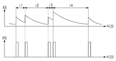
도 2는 도 1의 펄스 생성기의 동작에 따른 증폭 신호 및 펄스 신호의 예시적인 파형을 도시한 그래프이다. 도 2를 참조하면, 가로축은 시간으로 정의되고, 세로축은 증폭 신호(AS) 및 펄스 신호(PS)의 크기 (전압 또는 전류 레벨)로 정의된다. 증폭 신호(AS) 및 펄스 신호(PS) 각각은 도 1의 증폭 신호(AS) 및 펄스 신호(PS)에 대응된다. 설명의 편의상 도 1의 도면 부호를 참조하여, 도 2가 설명된다.2 is a graph showing exemplary waveforms of an amplified signal and a pulse signal according to an operation of the pulse generator of FIG. 1. Referring to FIG. 2, the horizontal axis is defined as time, and the vertical axis is defined as the magnitude (voltage or current level) of the amplified signal AS and the pulse signal PS. Each of the amplified signal AS and the pulse signal PS corresponds to the amplified signal AS and the pulse signal PS of FIG. 1. For convenience of explanation, FIG. 2 is described with reference to the reference numerals of FIG. 1.
증폭 신호(AS)는 소스 검출기(110)로부터 수신된 검출 신호(DS)를 전치 증폭기(121)를 이용하여 증폭한 신호일 수 있다. 증폭 신호(AS)는 5개의 피크 값을 가지므로, 방사성 동위원소로부터 5개의 입자들이 검출된 경우의 파형으로 이해될 것이다. 5개의 피크 값들 중 인접한 피크 값들 사이에 4개의 시간 간격들, 즉 제1 내지 제4 시간 간격들(i1~i4)이 존재한다. 제1 내지 제4 시간 간격들(i1~i4)은 난수(RN) 또는 이진 카운트 값들(CV)을 생성하는데 이용되며, 난수(RN)의 크기는 제1 내지 제4 시간 간격들(i1~i4) 각각의 길이에 의존한다.The amplified signal AS may be a signal obtained by amplifying the detection signal DS received from the
펄스 신호(PS)는 아날로그-디지털 변환기(122)를 이용하여 증폭 신호(AS)의 파형들을 디지털 신호인 사각 펄스로 처리한 신호일 수 있다. 일례로, 아날로그-디지털 변환기(122)는 증폭 신호(AS)로부터 5개의 극대값들을 추출할 수 있고, 제1 내지 제4 시간 간격들(i1~i4)로 분포된 펄스들을 생성할 수 있다. 5개의 펄스들 각각은 입자들(pt)이 검출된 시간에 대응된다. 이러한 펄스들은 카운터(130)에 입력된다. 카운터(130)는 제1 내지 제4 시간 간격들(i1~i4) 각각에 대응되는 카운트 값들을 생성할 수 있다.The pulse signal PS may be a signal obtained by processing the waveforms of the amplified signal AS into a square pulse, which is a digital signal, using the analog-to-
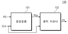
도 3은 도 1의 카운터의 예시적인 블록도이다. 도 3의 카운터(130)는 펄스들 사이의 시간 간격들 각각을 측정하여 이진 카운트 값들(CV)을 생성하는 예시적인 구성으로 이해될 것이다. 도 3을 참조하면, 카운터(130)는 플립플롭(131) 및 클럭 카운터(132)를 포함할 수 있다.3 is an exemplary block diagram of the counter of FIG. 1. The
플립플롭(131)은 펄스 신호(PS)에 포함된 펄스들을 클럭 신호(CLK)에 동기화하여 출력할 수 있다. 플립플롭(131)은 펄스 도 1의 펄스 생성기(120)로부터 생성된 펄스 신호(PS)를 수신한다. 상술한 바와 같이, 펄스 신호(PS)는 입자(pt)들 각각의 검출 시점에 대응되는 복수의 펄스들을 포함한다. 플립플롭(131)은 비동기적으로 생성된 펄스들을 클럭 신호(CLK)에 포함된 클럭들의 상승 엣지 또는 하강 엣지에 맞출 수 있다. 플립플롭(131)은 동기화된 펄스 신호(PSa)를 클럭 카운터(132)로 출력할 수 있다.The flip-
클럭 카운터(132)는 동기화된 펄스 신호(PSa)에 포함된 펄스들 사이의 시간 간격들 동안, 클럭들의 개수를 카운트할 수 있다. 클럭 카운터(132)에 하나의 펄스가 입력되면, 클럭 카운터(132)는 다음 펄스가 입력될 때까지의 시간 동안 입력되는 클럭들을 카운트할 수 있다. 클럭 카운터(132)는 카운트된 클럭들의 개수에 대응되는 이진 카운트 값(CV)을 생성할 수 있다. 이진 카운트 값(CV)은 0 값 또는 1 값을 갖는 비트열을 포함할 수 있다. 이진 카운트 값(CV)의 크기는 카운트된 클럭들의 개수에 의존한다. 즉, 카운트된 클럭들의 개수가 클수록, 이진 카운트 값(CV)의 크기는 증가한다. 펄스들은 소스의 랜덤한 입자(pt) 방출에 기초하여 생성되므로, 카운트된 클럭들의 개수는 랜덤할 수 있다. 따라서, 이진 카운트 값(CV)이 상술된 검증 회로(140)에 의하여 유효한 것으로 판단되는 경우, 이진 카운트 값(CV)은 난수로 사용된다.The
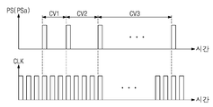
도 4는 도 1 및 도 3의 카운터의 동작을 설명하기 위한 그래프이다. 도 4를 참조하면, 가로축은 시간으로 정의되고, 세로축은 펄스 신호(PS) (또는 동기화된 펄스 신호(PSa)) 및 클럭 신호(CLK)의 크기 (전압 또는 전류 레벨)로 정의된다. 펄스 신호(PS), 동기화된 펄스 신호(PSa), 및 클럭 신호(CLK)는 도 3의 펄스 신호(PS), 동기화된 펄스 신호(PSa), 및 클럭 신호(CLK)에 대응된다.4 is a graph for explaining the operation of the counter of FIGS. 1 and 3. Referring to FIG. 4, the horizontal axis is defined as time, and the vertical axis is defined as the magnitude (voltage or current level) of the pulse signal PS (or synchronized pulse signal PSa) and the clock signal CLK. The pulse signal PS, the synchronized pulse signal PSa, and the clock signal CLK correspond to the pulse signal PS, the synchronized pulse signal PSa, and the clock signal CLK of FIG. 3.
펄스 신호(PS)는 도 1의 입자들(pt) 각각에 대응되는 펄스들을 포함한다. 동기화된 펄스 신호(PSa)는 도 3의 플립플롭(131)을 이용하여, 펄스들을 클럭 신호(CLK)의 상승 엣지 (또는 하강 엣지)에 동기화한 펄스들을 포함한다. 펄스들은 랜덤한 시간 간격으로 분포될 수 있다. 도 3의 클럭 카운터(132)는 펄스들 사이의 시간 간격들 동안, 클럭들의 개수를 카운트할 수 있다. The pulse signal PS includes pulses corresponding to each of the particles pt of FIG. 1. The synchronized pulse signal PSa includes pulses obtained by synchronizing the pulses with the rising edge (or falling edge) of the clock signal CLK using the flip-
도 4에서, 첫번째 펄스 및 두번째 펄스 사이의 시간 간격 동안 3개의 클럭들이 카운트될 수 있다. 설정된 이진 카운트 값의 비트 수가 4인 것으로 가정하면, 제1 이진 카운트 값(CV1)은 00112일 수 있다. 두번째 펄스 및 세번째 펄스 사이의 시간 간격 동안 4개의 클럭들이 카운트되고, 제2 이진 카운트 값(CV2)은 01002일 수 있다. 세번째 펄스 및 네번째 펄스 사이의 시간 간격 동안 10개의 클럭들이 카운트된다면, 제3 이진 카운트 값(CV3)은 10102일 수 있다. In FIG. 4, three clocks may be counted during the time interval between the first pulse and the second pulse. Assuming that the number of bits of the set binary count value is 4, the first binary count value CV1 may be 0011 2 . During a time interval between the second pulse and the third pulse, four clocks are counted, and the second binary count value CV2 may be 0 100 2 . If 10 clocks are counted during the time interval between the third pulse and the fourth pulse, the third binary count value CV3 may be 1010 2 .
다만, 이에 제한되지 않고, 제1 내지 제3 이진 카운트 값들(CV1~CV3)은 카운트된 클럭들의 개수와 동일한 값을 갖지 않을 수 있다. 일례로, 제1 이진 카운트 값(CV1)은 3개의 클럭들이 카운트될 때의 설정된 값을 가질 수 있다. 예를 들어, 설정된 값은 카운트된 클럭들의 개수에 비례하거나, 이진 카운트 값의 설정된 비트 수로 표현되는 범위 내로 보정된 값일 수 있다. However, the present invention is not limited thereto, and the first to third binary count values CV1 to CV3 may not have the same value as the number of counted clocks. For example, the first binary count value CV1 may have a set value when three clocks are counted. For example, the set value may be proportional to the number of counted clocks or may be a value corrected within a range expressed by the set number of bits of the binary count value.
펄스들이 랜덤한 시간 간격으로 분포되므로, 제1 내지 제3 이진 카운트 값들(CV1~CV3)은 도 1의 난수(RN)로 사용될 수 있다. 다만, 제1 내지 제3 이진 카운트 값들(CV1~CV3)은 신호의 전달, 변환, 변형 과정 등에서 노이즈 등이 포함된 결과일 수 있다. 일예로, 도 1에서 소스 검출기(110)가 입자(pt)를 검출하는 과정, 펄스 생성기(120)가 아날로그 신호를 증폭하고 디지털 펄스로 변환하는 과정 등에서 노이즈가 신호에 포함될 수 있다. 이 경우, 이진 카운트 값들의 신뢰성이 감소하고, 편향성을 가질 수 있다. 도 1의 검증 회로(140)는 카운터(130)로부터 생성된 이진 카운트 값들의 유효성을 검증할 수 있다.Since the pulses are distributed at random time intervals, the first to third binary count values CV1 to CV3 may be used as the random number RN of FIG. 1. However, the first to third binary count values CV1 to CV3 may be a result of including noise during signal transmission, conversion, and transformation. As an example, noise may be included in the signal in a process in which the
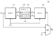
도 5는 도 1의 검증 회로의 예시적인 블록도이다. 도 5의 검증 회로(140)는 이진 카운트 값들(CV)의 분포를 판단하여 진성 난수에 가까운지 판단하는 예시적인 구성으로 이해될 것이다. 도 5를 참조하면, 검증 회로(140)는 비교기(141), 누적기(142), 판단기(145), 및 멀티플렉서(MUX)를 포함할 수 있다.5 is an exemplary block diagram of the verification circuit of FIG. 1. The
비교기(141)는 이진 카운트 값들(CV)에서 0 값들(C0) 및 1 값들(C1)을 추출한다. 이진 카운트 값들(CV)은 복수의 시간 간격들에 각각 대응된다. 하나의 이진 카운트 값은 하나의 시간 간격에 대응되고, 0 값 또는 1 값을 갖는 비트열을 포함한다. 이진 카운트 값들(CV)은 복수의 비트열들을 포함한다. 비교기(141)는 이진 카운트 값들(CV)의 비트들 각각의 크기를 기준 값과 비교하여 0 값들(C0)과 1 값들(C1)을 분리할 수 있다. 일례로, 기준 값은 0 값에 대응되는 디지털 신호의 크기와 1 값에 대응되는 디지털 신호의 크기 사이의 값일 수 있다. 0 값들(C0) 및 1 값들(C1)은 서로 분리되어 누적기(142)로 출력될 수 있다. 비교기(141)는 클럭 신호(CLK)에 동기화되어 동작할 수 있다.The
누적기(142)는 수신된 0 값들(C0) 및 1 값들(C1)을 각각 누적할 수 있다. 누적기(142)는 0 값들(C0)을 누적하여 0 값들(C0)의 개수에 대응되는 제1 누적 값(A1)을 생성할 수 있다. 누적기(142)는 1 값들(C1)을 누적하여 1 값들(C1)의 개수에 대응되는 제2 누적 값(A2)을 생성할 수 있다. 누적기(142)는 0 값들(C0)을 누적하여 제1 누적 값(A1)을 생성하는 제1 누적기(143), 및 1 값들(C1)을 누적하여 제2 누적 값(A2)을 생성하는 제2 누적기(144)를 포함할 수 있다. 제1 누적기(143)는 0 값들(C0)을 수신할 때마다 제1 누적 값(A1)을 증가시킬 수 있다. 제2 누적기(144)는 1 값들(C1)을 수신할 때마다 제2 누적 값(A2)을 증가시킬 수 있다.The
판단기(145)는 제1 누적 값(A1) 및 제2 누적 값(A2)의 차이에 기초하여 검증 신호(VS)를 생성할 수 있다. 판단기(145)는 클럭 신호(CLK)에 동기화되어 동작할 수 있다. 판단기(145)는 제1 누적 값(A1)과 제2 누적 값(A2)을 감산할 수 있다. 이러한 감산 값은 0 값들(C0)의 개수와 1 값들(C1)의 개수의 차이일 수 있다. 판단기(145)는 감산 값이 기준 범위 이내인지 판단할 수 있다. 여기에서, 기준 범위는 이진 카운트 값들(CV)이 난수(RN)로 사용될 수 있을 정도의 랜덤성을 확보한 것으로 인정되는 허용 오차 범위일 수 있다. 이상적으로, 표본이 충분히 크다면, 진성 난수에 대응되는 감산 값은 0에 수렴할 것이다. The
감산 값이 기준 범위 이내인 경우, 판단기(145)는 이진 카운트 값들(CV)이 유효한 것으로 판단하고, 활성화 값 (일례로, 1 값)을 갖는 검증 신호(VS)를 생성할 수 있다. 감산 값이 기준 범위를 벗어난 경우, 판단기(145)는 이진 카운트 값들(CV)이 유효한 진성 난수가 아닌 것으로 판단하고, 비활성화 값 (일례로, 0 값)을 갖는 검증 신호(VS)를 생성할 수 있다. 검증 신호(VS)는 멀티 플렉서(MUX)를 제어하는데 사용될 수 있다.When the subtraction value is within the reference range, the
멀티플렉서(MUX)는 검증 신호(VS)에 기초하여, 이진 카운트 값들(CV)을 난수(RN)로 출력하거나 출력하지 않을 수 있다. 검증 신호(VS)가 활성화 값 (일례로, 1 값)을 갖는 경우, 멀티플렉서(MUX)는 이진 카운트 값들(CV)을 난수(RN)로 출력할 수 있다. 출력된 난수(RN)는 암호 시스템과 같이, 난수(RN)가 요구되는 전자 시스템으로 제공될 수 있다. 검증 신호(VS)가 비활성화 값 (일례로, 0 값)을 갖는 경우, 멀티플렉서(MUX)는 이진 카운트 값들(CV)의 출력을 차단할 수 있다. 즉, 검증 회로(140)는 이진 카운트 값들(CV)의 유효성을 판단하여 난수(RN)로의 사용여부를 판단할 수 있다.The multiplexer MUX may or may not output the binary count values CV as random numbers RN based on the verification signal VS. When the verification signal VS has an activation value (for example, a value of 1), the multiplexer MUX may output the binary count values CV as random numbers RN. The output random number RN may be provided to an electronic system requiring a random number RN, such as an encryption system. When the verification signal VS has an inactive value (for example, a value of 0), the multiplexer MUX may block the output of the binary count values CV. That is, the
도 5의 검증 회로(140)는 상술된 0 값들 및 1 값들의 차이를 이용하여 이진 카운트 값들(CV)의 유효성을 판단하는 방식 이외에, 0 값들 또는 1 값들의 개수와 총 비트 수의 비율을 이용하여 이진 카운트 값들(CV)의 유효성을 판단할 수 있다. 이 경우, 비교기(141)는 이진 카운트 값들(CV)에서 0 값들(C0) 및 1 값들(C1) 중 어느 하나를 추출할 수 있다. 누적기(142)는 0 값들(C0)의 개수 또는 1 값들(C1)의 개수에 대응되는 누적 값을 생성할 수 있다. 그리고, 누적기(142)는 이진 카운트 값들(CV) 전체의 비트 수를 누적하여 누적 값을 생성할 수 있다. 예를 들어, 비교기(141)는 0 값들(C0)을 제1 누적기(143)로 출력하고, 제1 누적기(143)는 0 값들(C0)의 개수에 대응되는 제1 누적 값(A1)을 생성할 수 있다. 예를 들어, 비교기(141)는 이진 카운트 값들(CV) 전체를 제2 누적기(144)로 출력하고, 제2 누적기(144)는 이진 카운트 값들(CV)의 총 비트 수에 대응되는 제2 누적 값(A2)을 생성할 수 있다.The
제1 누적 값(A1)이 0 값들 또는 1 값들의 개수에 대응되고 제2 누적 값(A2)이 이진 카운트 값들(CV)의 총 비트 수에 대응되는 경우, 판단기(145)는 제2 누적 값(A2)에 대한 제1 누적 값(A1)의 비율에 기초하여 검증 신호(VS)를 생성할 수 있다. 판단기(145)는 제2 누적 값(A2)에 대한 제1 누적 값(A1)의 비율을 계산할 수 있다. 이러한 비율은 이진 카운트 값들(CV)의 총 비트 수에 대한 0 값들(C0) (또는 1 값들(C1))의 개수의 비율일 수 있다. 판단기(145)는 해당 비율이 기준 범위 이내인지 판단할 수 있다. 여기에서, 기준 범위는 이진 카운트 값들(CV)이 난수(RN)로 사용될 수 있을 정도의 랜덤성을 확보한 것으로 인정되는 허용 오차 범위일 수 있다. 이상적으로, 표본이 충분히 크다면, 진성 난수에 대응되는 비율은 50%에 수렴할 것이다.When the first accumulated value A1 corresponds to the number of 0 values or 1 values and the second accumulated value A2 corresponds to the total number of bits of the binary count values CV, the
해당 비율이 기준 범위 이내인 경우, 판단기(145)는 이진 카운트 값들(CV)이 유효한 것으로 판단하고, 활성화 값 (일례로, 1 값)을 갖는 검증 신호(VS)를 생성할 수 있다. 해당 비율이 기준 범위를 벗어난 경우, 판단기(145)는 이진 카운트 값들(CV)이 유효한 진성 난수가 아닌 것으로 판단하고, 비활성화 값 (일례로, 0 값)을 갖는 검증 신호(VS)를 생성할 수 있다. 검증 신호(VS)가 활성화 값 (일례로, 1 값)을 갖는 경우, 멀티플렉서(MUX)는 이진 카운트 값들(CV)을 난수(RN)로 출력할 수 있다. 검증 신호(VS)가 비활성화 값 (일례로, 0 값)을 갖는 경우, 멀티플렉서(MUX)는 이진 카운트 값들(CV)의 출력을 차단할 수 있다.If the ratio is within the reference range, the
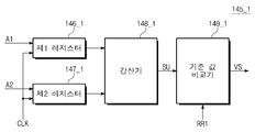
도 6은 도 5의 판단기의 예시적인 블록도이다. 도 6의 판단기(145_1)는 이진 카운트 값들(CV)에서 0 값들의 개수 및 1 값들의 개수의 차이에 기초하여 유효성을 판단하는 예시적인 구성으로 이해될 것이다. 도 6을 참조하면, 판단기(145_1)는 제1 레지스터(146_1), 제2 레지스터(147_1), 감산기(148_1), 및 기준 값 비교기(149_1)를 포함할 수 있다.6 is an exemplary block diagram of the determiner of FIG. 5. The determiner 145_1 of FIG. 6 will be understood as an exemplary configuration for determining validity based on a difference between the number of 0 values and the number of 1 values in the binary count values CV. Referring to FIG. 6, the determiner 145_1 may include a first register 146_1, a second register 147_1, a subtractor 148_1, and a reference value comparator 149_1.
제1 레지스터(146_1)는 제1 누적 값(A1)을 임시 저장하고, 제2 레지스터(147_1)는 제2 누적 값(A2)을 임시 저장한다. 제1 레지스터(146_1) 및 제2 레지스터(147_1)는 클럭 신호(CLK)에 동기화되어 동작할 수 있다. 제1 누적 값(A1)은 도 5의 0 값들(C0)의 개수에 대응되고, 제2 누적 값(A2)은 도 5의 1 값들(C1)의 개수에 대응된다. 제1 레지스터(146_1) 및 제2 레지스터(147_1)는 클럭 신호(CLK)에 기초하여, 제1 누적 값(A1) 및 제2 누적 값(A2)을 감산기(148_1)로 출력할 수 있다.The first register 146_1 temporarily stores the first accumulated value A1, and the second register 147_1 temporarily stores the second accumulated value A2. The first register 146_1 and the second register 147_1 may operate in synchronization with the clock signal CLK. The first accumulated value A1 corresponds to the number of 0 values C0 in FIG. 5, and the second accumulated value A2 corresponds to the number of 1 values C1 in FIG. 5. The first register 146_1 and the second register 147_1 may output the first accumulated value A1 and the second accumulated value A2 to the subtractor 148_1 based on the clock signal CLK.
감산기(148_1)는 제1 누적 값(A1) 및 제2 누적 값(A2)의 차이를 계산할 수 있다. 이러한 차이는 0 값들(C0)의 개수와 1 값들(C1)의 개수의 차이일 수 있다. 감산기(148_1)는 이진 카운트 값들(CV)의 0 개수와 1 개수의 차이에 대응되는 감산 값(SU)을 생성하여, 기준 값 비교기(149_1)로 출력할 수 있다.The subtractor 148_1 may calculate a difference between the first accumulated value A1 and the second accumulated value A2. This difference may be a difference between the number of 0 values C0 and the number of 1 values C1. The subtractor 148_1 may generate a subtraction value SU corresponding to a difference between the number of zeros and ones of the binary count values CV and output to the reference value comparator 149_1.
기준 값 비교기(149_1)는 감산 값(SU)이 기준 범위(RR1) 이내인지 판단할 수 있다. 여기에서, 기준 범위(RR1)는 이진 카운트 값들(CV)이 난수(RN)로 사용될 수 있을 정도의 랜덤성을 확보한 것으로 인정되는 허용 오차 범위일 수 있다. 일례로, 기준 범위(RR1)는 0을 기준으로 허용 오차 범위만큼 대칭된 상한 및 하한을 가질 수 있다. 감산 값(SU)이 기준 범위(RR1) 이내인 경우, 기준 값 비교기(149_1)는 활성화 값 (일례로, 1 값)을 갖는 검증 신호(VS)를 생성할 수 있다. 감산 값(SU)이 기준 범위(RR1)를 벗어난 경우, 기준 값 비교기(149_1)는 비활성화 값 (일례로, 0 값)을 갖는 검증 신호(VS)를 생성할 수 있다.The reference value comparator 149_1 may determine whether the subtracted value SU is within the reference range RR1. Here, the reference range RR1 may be an allowable error range recognized as securing randomness enough that the binary count values CV can be used as the random number RN. As an example, the reference range RR1 may have an upper limit and a lower limit symmetrical by an allowable error range based on 0. When the subtraction value SU is within the reference range RR1, the reference value comparator 149_1 may generate a verification signal VS having an activation value (for example, a value of 1). When the subtracted value SU is out of the reference range RR1, the reference value comparator 149_1 may generate a verification signal VS having an inactive value (eg, a value of 0).
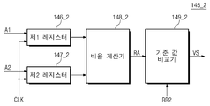
도 7은 도 5의 판단기의 예시적인 블록도이다. 도 7의 판단기(145_2)는 이진 카운트 값들(CV)의 총 비트 수에 대한 0 값들의 개수 (또는 1 값들의 개수)의 비율에 기초하여 유효성을 판단하는 예시적인 구성으로 이해될 것이다. 도 7을 참조하면, 판단기(145_2)는 제1 레지스터(146_2), 제2 레지스터(147_2), 비율 계산기(148_2), 및 기준 값 비교기(149_2)를 포함할 수 있다.7 is an exemplary block diagram of the determiner of FIG. 5. The determiner 145_2 of FIG. 7 will be understood as an exemplary configuration for determining validity based on a ratio of the number of 0 values (or the number of 1 values) to the total number of bits of the binary count values CV. Referring to FIG. 7, the determiner 145_2 may include a first register 146_2, a second register 147_2, a ratio calculator 148_2, and a reference value comparator 149_2.
제1 레지스터(146_2)는 제1 누적 값(A1)을 임시 저장하고, 제2 레지스터(147_2)는 제2 누적 값(A2)을 임시 저장한다. 제1 레지스터(146_2) 및 제2 레지스터(147_2)는 클럭 신호(CLK)에 동기화되어 동작할 수 있다. 제1 누적 값(A1)은 이진 카운트 값들(CV)에 포함된 0 값들의 개수 또는 1 값들의 개수에 대응될 수 있다. 제2 누적 값(A2)은 이진 카운트 값들(CV)의 총 비트 수에 대응될 수 있다. 제1 레지스터(146_2) 및 제2 레지스터(147_2)는 클럭 신호(CLK)에 기초하여, 제1 누적 값(A1) 및 제2 누적 값(A2)을 비율 계산기(148_2)로 출력할 수 있다.The first register 146_2 temporarily stores the first accumulated value A1, and the second register 147_2 temporarily stores the second accumulated value A2. The first register 146_2 and the second register 147_2 may operate in synchronization with the clock signal CLK. The first cumulative value A1 may correspond to the number of 0 values or 1 values included in the binary count values CV. The second accumulated value A2 may correspond to the total number of bits of the binary count values CV. The first register 146_2 and the second register 147_2 may output the first accumulated value A1 and the second accumulated value A2 to the ratio calculator 148_2 based on the clock signal CLK.
비율 계산기(148_2)는 제2 누적 값(A2)에 대한 제1 누적 값(A1)의 비율을 계산할 수 있다. 이러한 비율은 이진 카운트 값들(CV)의 총 비트 수에 대한 0 값들(C0) (또는 1 값들(C1))의 개수의 비율일 수 있다. 비율 계산기(148_2)는 제1 누적 값(A1)을 제2 누적 값(A2)으로 나누어 비율 값(RA)을 생성할 수 있다.The ratio calculator 148_2 may calculate a ratio of the first accumulated value A1 to the second accumulated value A2. This ratio may be a ratio of the number of 0 values C0 (or 1 values C1) to the total number of bits of the binary count values CV. The ratio calculator 148_2 may generate a ratio value RA by dividing the first accumulated value A1 by the second accumulated value A2.
기준 값 비교기(149_2)는 비율 값(RA)이 기준 범위(RR2) 이내인지 판단할 수 있다. 여기에서, 기준 범위(RR2)는 이진 카운트 값들(CV)이 난수(RN)로 사용될 수 있을 정도의 랜덤성을 확보한 것으로 인정되는 허용 오차 범위일 수 있다. 일례로, 기준 범위(RR2)는 0.5(50%)를 기준으로 허용 오차 범위만큼 대칭된 상한 및 하한을 가질 수 있다. 비율 값(RA)이 기준 범위(RR2) 이내인 경우, 기준 값 비교기(149_2)는 활성화 값 (일례로, 1 값)을 갖는 검증 신호(VS)를 생성할 수 있다. 비율 값(RA)이 기준 범위(RR2)를 벗어난 경우, 기준 값 비교기(149_2)는 비활성화 값 (일례로, 0 값)을 갖는 검증 신호(VS)를 생성할 수 있다.The reference value comparator 149_2 may determine whether the ratio value RA is within the reference range RR2. Here, the reference range RR2 may be an allowable error range recognized as securing randomness enough that the binary count values CV can be used as the random number RN. For example, the reference range RR2 may have upper and lower limits symmetrical by an allowable error range based on 0.5 (50%). When the ratio value RA is within the reference range RR2, the reference value comparator 149_2 may generate a verification signal VS having an activation value (for example, a value of 1). When the ratio value RA is out of the reference range RR2, the reference value comparator 149_2 may generate a verification signal VS having an inactive value (for example, a value of 0).
도 8은 도 1의 난수 생성 장치의 동작 방법의 예시적인 순서도이다. 도 8의 단계들은 도 1 내지 도 7에서 설명된 난수 생성 장치(100)에서 수행될 수 있다. 설명의 편의상 도 1의 도면 부호를 참조하여, 도 8이 설명된다.8 is an exemplary flowchart of a method of operating the random number generating apparatus of FIG. 1. The steps of FIG. 8 may be performed in the random
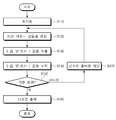
S110 단계에서, 난수 생성 장치(100)는 초기화 동작을 수행한다. 일례로, 초기화 동작 이전에 수행된 난수 생성 과정에서 저장된 값들, 신호들 등이 리셋될 수 있다.In step S110, the random
S120 단계에서, 난수 생성 장치(100)의 카운터(130)는 이진 카운트 값들(CV)을 생성한다. 이를 위하여, 소스 검출기(110)는 소스로부터 방출된 입자들(pt)을 검출하여 검출 신호(DS)를 생성할 수 있다. 펄스 생성기(120)는 검출된 입자들(pt) 각각의 검출 시간에 대응되는 펄스들을 생성할 수 있다. 카운터(130)는 펄스들 사이의 시간 간격들 동안 클럭들의 개수를 카운트하여 이진 카운트 값들(CV)을 생성할 수 있다.In step S120, the
S130 단계에서, 난수 생성 장치(100)의 검증 회로(140)는 이진 카운트 값들(CV)에서 0 값들 및/또는 1 값들을 추출한다. S130 단계는 도 5의 비교기(141)에서 수행될 수 있다. 0 값들의 개수 및 1 값들의 개수의 차이에 기초하여 유효성을 판단하는 실시예에서, 비교기(141)는 0 값들 및 1 값들을 추출할 수 있다. 이진 카운트 값들(CV)의 총 비트 수에 대한 0 값들의 개수 (또는 1 값들의 개수)의 비율에 기초하여 유효성을 판단하는 실시예에서, 비교기(141)는 0 값들을 추출하거나 1 값들을 추출할 수 있다.In step S130, the
S140 단계에서, 난수 생성 장치(100)의 검증 회로(140)는 추출된 0 값들 및/또는 1 값들을 누적할 수 있다. S140 단계는 도 5의 누적기(142)에서 수행될 수 있다. 0 값들의 개수 및 1 값들의 개수의 차이에 기초하여 유효성을 판단하는 실시예에서, 누적기(142)는 0 값들의 개수에 대응되는 제1 누적 값을 생성하고, 1 값들의 개수에 대응되는 제2 누적 값을 생성할 수 있다. 총 비트 수에 대한 0 값들의 개수 (또는 1 값들의 개수)의 비율에 기초하여 유효성을 판단하는 실시예에서, 누적기(142)는 0 값들의 개수 또는 1 값들의 개수에 대응되는 제1 누적 값을 생성하고, 이진 카운트 값들(CV)의 총 비트 수에 대응되는 제2 누적 값을 생성할 수 있다.In step S140, the
S150 단계에서, 난수 생성 장치(100)의 검증 회로(140)는 0 값들의 개수 및 1 값들의 개수의 차이가 기준 범위 이내인지 판단할 수 있다. 이러한 동작은 도 6의 판단기(145_1)에서 수행될 수 있다. 판단기(145_1)는 제1 누적 값과 제2 누적 값을 감산하고 감산 값이 기준 범위 이내인지 판단할 수 있다.In operation S150, the
또는, S150 단계에서, 검증 회로(140)는 이진 카운트 값들(CV)의 총 비트 수에 대한 0 값들의 개수 (또는 1 값들의 개수)의 비율이 기준 범위 이내인지 판단할 수 있다. 이러한 동작은 도 7의 판단기(145_2)에서 수행될 수 있다. 판단기(145_2)는 제2 누적 값에 대한 제1 누적 값의 비율을 계산하고, 비율 값이 기준 범위 이내인지 판단할 수 있다.Alternatively, in step S150, the
감산 값 또는 비율 값이 기준 범위 이내인 경우, S160 단계가 진행된다. S160 단계에서, 검증 회로(140)는 이진 카운트 값들(CV)을 난수(RN)로 출력한다. 감산 값 또는 비율 값이 기준 범위 이내인 경우, 검증 회로(140)는 이진 카운트 값들(CV)이 유효한 것으로 판단하고, 활성화 값 (일례로, 1 값)을 갖는 검증 신호(VS)를 생성할 수 있다. 검증 신호(VS)는 도 5의 멀티플렉서(MUX)에 입력되고, 멀티플렉서(MUX)는 활성화 값에 기초하여 이진 카운트 값들(CV)을 난수(RN)로 출력할 수 있다.If the subtraction value or the ratio value is within the reference range, step S160 proceeds. In step S160, the
감산 값 또는 비율 값이 기준 범위를 벗어난 경우, S170 단계가 진행된다. S170 단계에서, 검증 회로(140)는 이진 카운트 값들(CV)의 출력을 차단한다. 감산 값 또는 비율 값이 기준 범위를 벗어난 경우, 검증 회로(140)는 이진 카운트 값들(CV)이 유효한 진성 난수가 아닌 것으로 판단하고, 비활성화 값 (일례로, 0 값)을 갖는 검증 신호(VS)를 생성할 수 있다. 검증 신호(VS)는 도 5의 멀티플렉서(MUX)에 입력되고, 멀티플렉서(MUX)는 비활성화 값에 기초하여 이진 카운트 값들(CV)을 출력하지 않을 수 있다.If the subtraction value or the ratio value is out of the reference range, step S170 proceeds. In step S170, the
위에서 설명한 내용은 본 발명을 실시하기 위한 구체적인 예들이다. 본 발명에는 위에서 설명한 실시 예들뿐만 아니라, 단순하게 설계 변경하거나 용이하게 변경할 수 있는 실시 예들도 포함될 것이다. 또한, 본 발명에는 상술한 실시 예들을 이용하여 앞으로 용이하게 변형하여 실시할 수 있는 기술들도 포함될 것이다.The contents described above are specific examples for carrying out the present invention. The present invention will include not only the embodiments described above, but also embodiments that can be changed in design or easily changed. In addition, the present invention will also include techniques that can be easily modified and implemented in the future using the above-described embodiments.
100: 난수 생성 장치
110: 소스 검출기
120: 펄스 생성기
121: 전치 증폭기
122: 아날로그-디지털 변환기
130: 카운터
131: 플립플롭
132: 클럭 카운터
140: 검증 회로
141: 비교기
142: 누적기
145, 145_1, 145_2: 판단기
150: 컨트롤러
MUX: 멀티플렉서100: random number generator 110: source detector
120: pulse generator 121: preamplifier
122: analog-to-digital converter 130: counter
131: flip-flop 132: clock counter
140: verification circuit 141: comparator
142:
150: controller MUX: multiplexer
Claims (20)
상기 검출 신호에 기초하여 상기 검출된 입자들에 대응되는 펄스들을 생성하는 펄스 생성기;
상기 펄스들 사이의 시간 간격들을 측정하고, 상기 시간 간격들에 각각 대응되는 이진 카운트 값들을 생성하는 카운터; 및
상기 이진 카운트 값들에 포함된 0 값들의 개수 및 1 값들의 개수에 기초하여 상기 이진 카운트 값들의 출력을 결정하는 검증 회로를 포함하는 난수 생성 장치.A source detector detecting particles emitted from a source to generate a detection signal;
A pulse generator that generates pulses corresponding to the detected particles based on the detection signal;
A counter measuring time intervals between the pulses and generating binary count values corresponding to the time intervals; And
And a verification circuit configured to determine outputs of the binary count values based on the number of 0 values and the number of 1 values included in the binary count values.
상기 검증 회로는,
상기 이진 카운트 값들에서 상기 0 값들 및 상기 1 값들을 추출하는 비교기;
상기 0 값들의 개수에 대응되는 제1 누적 값을 생성하고, 상기 1 값들의 개수에 대응되는 제2 누적 값을 생성하는 누적기;
상기 제1 누적 값 및 상기 제2 누적 값의 차이에 기초하여 상기 이진 카운트 값들의 유효성을 검증하기 위한 검증 신호를 생성하는 판단기; 및
상기 검증 신호에 기초하여 상기 이진 카운트 값들을 출력하는 멀티플렉서를 포함하는 난수 생성 장치.The method of claim 1,
The verification circuit,
A comparator for extracting the 0 values and the 1 values from the binary count values;
An accumulator that generates a first cumulative value corresponding to the number of 0 values and a second cumulative value corresponding to the number of 1 values;
A determiner for generating a verification signal for verifying validity of the binary count values based on a difference between the first accumulated value and the second accumulated value; And
A random number generation apparatus including a multiplexer that outputs the binary count values based on the verification signal.
상기 차이가 기준 범위 이내인 경우, 상기 판단기는 활성화 값을 갖는 상기 검증 신호를 생성하고, 상기 멀티플렉서는 상기 활성화 값에 응답하여 상기 이진 카운트 값들을 출력하는 난수 생성 장치.The method of claim 2,
When the difference is within a reference range, the determiner generates the verification signal having an activation value, and the multiplexer outputs the binary count values in response to the activation value.
상기 차이가 기준 범위를 벗어난 경우, 상기 판단기는 비활성화 값을 갖는 상기 검증 신호를 생성하고, 상기 멀티플렉서는 상기 비활성화 값에 응답하여 상기 이진 카운트 값들의 출력을 차단하는 난수 생성 장치.The method of claim 2,
When the difference is out of a reference range, the determiner generates the verification signal having a deactivation value, and the multiplexer blocks output of the binary count values in response to the deactivation value.
상기 판단기는,
상기 제1 누적 값 및 상기 제2 누적 값의 상기 차이를 계산하는 감산기; 및
상기 차이를 기준 범위와 비교하고, 비교 결과에 기초하여 상기 검증 신호를 생성하는 기준 값 비교기를 포함하는 난수 생성 장치.The method of claim 2,
The judgment unit,
A subtractor for calculating the difference between the first accumulated value and the second accumulated value; And
A random number generating apparatus comprising a reference value comparator for comparing the difference with a reference range and generating the verification signal based on a result of the comparison.
상기 누적기는,
상기 0 값들을 수신할 때 상기 제1 누적 값을 증가시키는 제1 누적기; 및
상기 1 값들을 수신할 때 상기 제2 누적 값을 증가시키는 제2 누적기를 포함하고,
상기 비교기는 상기 0 값들 및 상기 1 값들을 분리하고, 상기 0 값들을 상기 제1 누적기로 출력하고, 상기 1 값들을 상기 제2 누적기로 출력하는 난수 생성 장치.The method of claim 2,
The accumulator,
A first accumulator that increases the first accumulated value when receiving the zero values; And
A second accumulator that increases the second accumulated value when receiving the first values,
The comparator separates the 0 values and the 1 values, outputs the 0 values to the first accumulator, and outputs the 1 values to the second accumulator.
상기 카운터는,
상기 펄스들을 클럭 신호에 동기화하여 출력하는 플립플롭; 및
상기 동기화된 펄스들 사이의 시간 간격들 동안, 상기 클럭 신호에 포함된 클럭들의 개수를 카운트하여 상기 이진 카운트 값들을 생성하는 클럭 카운터를 포함하는 난수 생성 장치.The method of claim 1,
The counter is,
A flip-flop for synchronizing and outputting the pulses to a clock signal; And
And a clock counter to generate the binary count values by counting the number of clocks included in the clock signal during time intervals between the synchronized pulses.
기준 시간 동안 생성된 상기 펄스들에 기초하여 상기 이진 카운트 값들을 생성하도록 상기 카운터를 제어하고, 상기 이진 카운트 값들의 출력을 결정하도록 상기 검증 회로를 제어하는 컨트롤러를 더 포함하는 난수 생성 장치.The method of claim 1,
The random number generating apparatus further comprises a controller configured to control the counter to generate the binary count values based on the pulses generated during a reference time, and to control the verification circuit to determine outputs of the binary count values.
상기 이진 카운트 값들의 총 비트 수가 기준 개수일 때까지 상기 이진 카운트 값들을 생성하도록 상기 카운터를 제어하고, 상기 이진 카운트 값들의 출력을 결정하도록 상기 검증 회로를 제어하는 컨트롤러를 더 포함하는 난수 생성 장치.The method of claim 1,
The random number generating apparatus further comprises a controller controlling the counter to generate the binary count values until the total number of bits of the binary count values is a reference number, and controlling the verification circuit to determine the output of the binary count values.
상기 펄스 생성기는,
상기 검출 신호를 증폭하는 전치 증폭기; 및
상기 증폭된 검출 신호를 상기 펄스들로 변환하는 아날로그-디지털 변환기를 포함하는 난수 생성 장치.The method of claim 1,
The pulse generator,
A pre-amplifier amplifying the detection signal; And
A random number generator comprising an analog-to-digital converter converting the amplified detection signal into the pulses.
상기 소스는 베타선 소스이고, 상기 입자들 각각은 베타선에 대응되는 난수 생성 장치.The method of claim 1,
The source is a beta ray source, and each of the particles is a random number generating device corresponding to the beta ray.
상기 검출 신호를 상기 검출된 입자들에 대응되는 펄스들로 변환하는 펄스 생성기;
상기 펄스들 사이의 시간 간격들 동안 클럭들의 개수를 카운트하여 이진 카운트 값들을 생성하는 카운터; 및
상기 이진 카운트 값들의 총 비트 수에 대한 타겟 값들의 개수의 비율에 기초하여 상기 이진 카운트 값들의 출력을 결정하는 검증 회로를 포함하는 난수 생성 장치.A source detector detecting particles emitted from a source to generate a detection signal;
A pulse generator that converts the detection signal into pulses corresponding to the detected particles;
A counter that counts the number of clocks during time intervals between the pulses to generate binary count values; And
And a verification circuit that determines the output of the binary count values based on a ratio of the number of target values to the total number of bits of the binary count values.
상기 타겟 값들의 개수는 상기 이진 카운트 값들에 포함된 0 값들의 개수이거나, 상기 이진 카운트 값들에 포함된 1 값들의 개수인 난수 생성 장치. The method of claim 12,
The number of target values is the number of 0 values included in the binary count values or the number of 1 values included in the binary count values.
상기 검증 회로는,
상기 이진 카운트 값들에서 상기 타겟 값들을 추출하는 비교기;
상기 타겟 값들의 개수에 대응되는 누적 값을 생성하는 누적기;
상기 누적 값에 기초하여 상기 비율을 계산하고, 상기 비율에 기초하여 상기 이진 카운트 값들의 유효성을 검증하기 위한 검증 신호를 생성하는 판단기; 및
상기 검증 신호에 기초하여 상기 이진 카운트 값들을 출력하는 멀티플렉서를 포함하는 난수 생성 장치.The method of claim 12,
The verification circuit,
A comparator for extracting the target values from the binary count values;
An accumulator that generates an accumulated value corresponding to the number of target values;
A determiner that calculates the ratio based on the accumulated value and generates a verification signal for validating the validity of the binary count values based on the ratio; And
A random number generation apparatus including a multiplexer that outputs the binary count values based on the verification signal.
상기 비율이 기준 범위 이내인 경우, 상기 판단기는 활성화 값을 갖는 상기 검증 신호를 생성하고, 상기 멀티플렉서는 상기 활성화 값에 응답하여 상기 이진 카운트 값들을 출력하는 난수 생성 장치.The method of claim 14,
When the ratio is within a reference range, the determiner generates the verification signal having an activation value, and the multiplexer outputs the binary count values in response to the activation value.
상기 비율이 기준 범위를 벗어난 경우, 상기 판단기는 비활성화 값을 갖는 상기 검증 신호를 생성하고, 상기 멀티플렉서는 상기 비활성화 값에 응답하여 상기 이진 카운트 값들의 출력을 차단하는 난수 생성 장치.The method of claim 14,
When the ratio is out of a reference range, the determiner generates the verification signal having a deactivation value, and the multiplexer blocks output of the binary count values in response to the deactivation value.
소스로부터 방출되는 입자들이 검출된 시간 간격들에 대응되는 이진 카운트 값들을 생성하는 단계;
상기 이진 카운트 값들에서 0 값들 및 1 값들을 추출하는 단계;
상기 0 값들의 개수에 대응되는 제1 누적 값을 생성하는 단계;
상기 1 값들의 개수에 대응되는 제2 누적 값을 생성하는 단계;
상기 제1 누적 값 및 상기 제2 누적 값의 차이에 기초하여 상기 이진 카운트 값들의 유효성을 검증하기 위한 검증 신호를 생성하는 단계; 및
상기 검증 신호에 기초하여 상기 이진 카운트 값들의 출력여부를 판단하는 단계를 포함하는 방법.In the method of operating the random number generator,
Generating binary count values corresponding to time intervals in which particles emitted from the source are detected;
Extracting 0 values and 1 values from the binary count values;
Generating a first cumulative value corresponding to the number of zero values;
Generating a second cumulative value corresponding to the number of the first values;
Generating a verification signal for verifying validity of the binary count values based on a difference between the first accumulated value and the second accumulated value; And
And determining whether to output the binary count values based on the verification signal.
상기 검증 신호를 생성하는 단계는,
상기 제1 누적 값 및 상기 제2 누적 값의 차이를 계산하는 단계;
상기 차이와 기준 범위를 비교하는 단계; 및
상기 차이가 상기 기준 범위 이내인지 판단하는 단계를 포함하는 방법.The method of claim 17,
Generating the verification signal,
Calculating a difference between the first accumulated value and the second accumulated value;
Comparing the difference and a reference range; And
And determining whether the difference is within the reference range.
상기 이진 카운트 값들의 출력여부를 판단하는 단계는,
상기 차이가 상기 기준 범위 이내인 경우 상기 이진 카운트 값들을 난수로 출력하는 단계를 포함하는 방법.The method of claim 18,
The step of determining whether to output the binary count values,
And outputting the binary count values as random numbers when the difference is within the reference range.
상기 이진 카운트 값들의 출력여부를 판단하는 단계는,
상기 차이가 상기 기준 범위를 벗어난 경우 상기 이진 카운트 값들의 출력을 차단하는 단계를 포함하는 방법.
The method of claim 18,
The step of determining whether to output the binary count values,
And blocking the output of the binary count values when the difference is out of the reference range.
Priority Applications (2)
| Application Number | Priority Date | Filing Date | Title |
|---|---|---|---|
| KR1020190071664A KR102792398B1 (en) | 2019-06-17 | 2019-06-17 | Random number generating device and operating method of the same |
| US16/891,405 US11177817B2 (en) | 2019-06-17 | 2020-06-03 | Random number generating device and operating method of the same |
Applications Claiming Priority (1)
| Application Number | Priority Date | Filing Date | Title |
|---|---|---|---|
| KR1020190071664A KR102792398B1 (en) | 2019-06-17 | 2019-06-17 | Random number generating device and operating method of the same |
Publications (2)
| Publication Number | Publication Date |
|---|---|
| KR20200144192A true KR20200144192A (en) | 2020-12-29 |
| KR102792398B1 KR102792398B1 (en) | 2025-04-10 |
Family
ID=73745312
Family Applications (1)
| Application Number | Title | Priority Date | Filing Date |
|---|---|---|---|
| KR1020190071664A Active KR102792398B1 (en) | 2019-06-17 | 2019-06-17 | Random number generating device and operating method of the same |
Country Status (2)
| Country | Link |
|---|---|
| US (1) | US11177817B2 (en) |
| KR (1) | KR102792398B1 (en) |
Cited By (3)
| Publication number | Priority date | Publication date | Assignee | Title |
|---|---|---|---|---|
| KR20230053343A (en) * | 2021-10-14 | 2023-04-21 | 충북대학교 산학협력단 | Performance improving method of true random number generator |
| KR20230090116A (en) * | 2021-12-14 | 2023-06-21 | 한국원자력연구원 | Apparatus and method for entropy generation |
| KR20230112336A (en) * | 2022-01-20 | 2023-07-27 | 충남대학교산학협력단 | Method and Device for Generating True Random Number |
Families Citing this family (2)
| Publication number | Priority date | Publication date | Assignee | Title |
|---|---|---|---|---|
| KR102372740B1 (en) * | 2019-04-09 | 2022-03-14 | 한국전자통신연구원 | Random number generating device and operating method of the same |
| US11329811B1 (en) * | 2021-03-15 | 2022-05-10 | Motorola Mobility Llc | Quantum-based security for hardware devices |
Citations (4)
| Publication number | Priority date | Publication date | Assignee | Title |
|---|---|---|---|---|
| US20030050943A1 (en) * | 2001-09-07 | 2003-03-13 | Nec Corporation | Random number generating method and random number generating device |
| US6697829B1 (en) * | 1998-02-12 | 2004-02-24 | Aea Technology Plc | Method of and apparatus for generating random numbers |
| US20050198091A1 (en) * | 2002-08-14 | 2005-09-08 | Takeshi Saito | Apparatus and method for generating random numbers |
| US20160328211A1 (en) * | 2011-09-30 | 2016-11-10 | Los Alamos National Security, Llc | Quantum random number generators |
Family Cites Families (8)
| Publication number | Priority date | Publication date | Assignee | Title |
|---|---|---|---|---|
| US5911009A (en) * | 1996-01-25 | 1999-06-08 | Dainippon Screen Mfg. Co., Ltd. | Method and apparatus for binary coding of image data including adding error accumulated for a target pixel and a pixel in the vicinity to be later coded |
| JP2980576B2 (en) | 1997-09-12 | 1999-11-22 | 株式会社東芝 | Physical random number generating apparatus and method, and physical random number recording medium |
| JPH11161473A (en) | 1997-11-25 | 1999-06-18 | Norihei Tsuyusaki | Random number generator and probability generator |
| KR101488270B1 (en) | 2013-05-27 | 2015-01-30 | 한국전자통신연구원 | Apparatus and method for extracting noisy entropy source for random number generator |
| KR101557761B1 (en) | 2014-02-12 | 2015-10-06 | 한국전자통신연구원 | Apparatus and method for stabilizing output stream of real random number generator |
| US10387804B2 (en) * | 2014-09-30 | 2019-08-20 | BoonLogic | Implementations of, and methods of use for a pattern memory engine applying associative pattern memory for pattern recognition |
| DE102015102602A1 (en) | 2015-02-24 | 2016-08-25 | Infineon Technologies Ag | Random number generator |
| KR102200221B1 (en) | 2015-05-13 | 2021-01-11 | 한국전자통신연구원 | Multiple output quantum random number generator |
-
2019
- 2019-06-17 KR KR1020190071664A patent/KR102792398B1/en active Active
-
2020
- 2020-06-03 US US16/891,405 patent/US11177817B2/en active Active
Patent Citations (4)
| Publication number | Priority date | Publication date | Assignee | Title |
|---|---|---|---|---|
| US6697829B1 (en) * | 1998-02-12 | 2004-02-24 | Aea Technology Plc | Method of and apparatus for generating random numbers |
| US20030050943A1 (en) * | 2001-09-07 | 2003-03-13 | Nec Corporation | Random number generating method and random number generating device |
| US20050198091A1 (en) * | 2002-08-14 | 2005-09-08 | Takeshi Saito | Apparatus and method for generating random numbers |
| US20160328211A1 (en) * | 2011-09-30 | 2016-11-10 | Los Alamos National Security, Llc | Quantum random number generators |
Cited By (3)
| Publication number | Priority date | Publication date | Assignee | Title |
|---|---|---|---|---|
| KR20230053343A (en) * | 2021-10-14 | 2023-04-21 | 충북대학교 산학협력단 | Performance improving method of true random number generator |
| KR20230090116A (en) * | 2021-12-14 | 2023-06-21 | 한국원자력연구원 | Apparatus and method for entropy generation |
| KR20230112336A (en) * | 2022-01-20 | 2023-07-27 | 충남대학교산학협력단 | Method and Device for Generating True Random Number |
Also Published As
| Publication number | Publication date |
|---|---|
| US11177817B2 (en) | 2021-11-16 |
| KR102792398B1 (en) | 2025-04-10 |
| US20200395947A1 (en) | 2020-12-17 |
Similar Documents
| Publication | Publication Date | Title |
|---|---|---|
| KR102792398B1 (en) | Random number generating device and operating method of the same | |
| US5987483A (en) | Random number generator based on directional randomness associated with naturally occurring random events, and method therefor | |
| Barbashina et al. | The URAGAN wide-aperture large-area muon hodoscope | |
| US11372623B2 (en) | Random number generating device and operating method of the same | |
| US4864140A (en) | Coincidence detection system for positron emission tomography | |
| US11080022B2 (en) | Random number generator, in particular improved true random number generator | |
| CN101980146A (en) | A True Random Number Generator Based on Photon Number-Resolvable Detection | |
| WO2016016741A1 (en) | True random number generator | |
| JP2002533800A (en) | Random number generator based on spontaneous alpha decay | |
| Balygin et al. | A quantum random number generator based on the 100-Mbit/s Poisson photocount statistics | |
| Beissel et al. | The trigger and timing system of the Double Chooz experiment | |
| Akerib et al. | FPGA-based trigger system for the LUX dark matter experiment | |
| Park et al. | QEC: A quantum entropy chip and its applications | |
| US12217022B2 (en) | Systems and methods for direct random information generation from quantum random events | |
| US20210344488A1 (en) | Device and method for generating random bit sequences | |
| US12535993B1 (en) | System and method for preprocessing and conditioning cosmic ray data for randomness generation | |
| Hedges et al. | First 3D vector tracking of helium recoils for fast neutron measurements at SuperKEKB | |
| Vacheret et al. | The front end readout system for the T2K-ND280 detectors | |
| Rohe | RANDy-A true-random generator based on radioactive decay | |
| Basso et al. | A Starry Byte—proton beam measurements of single event upsets and other radiation effects in ABCStar ASIC Versions 0 and 1 for the ITk strip tracker | |
| KR20210097265A (en) | Random number generating device using machine learning algorithm | |
| RU192980U1 (en) | Ionizing radiation detection device for position sensitive systems | |
| Zhang et al. | Track identification and reconstruction in fast neutron detection by MPGD | |
| Tsyganov | Automation of experiments at Dubna Gas-Filled Recoil Separator | |
| Naumov et al. | The digital trigger system for the RED-100 detector |
Legal Events
| Date | Code | Title | Description |
|---|---|---|---|
| PA0109 | Patent application |
Patent event code: PA01091R01D Comment text: Patent Application Patent event date: 20190617 |
|
| PG1501 | Laying open of application | ||
| PA0201 | Request for examination |
Patent event code: PA02012R01D Patent event date: 20220504 Comment text: Request for Examination of Application Patent event code: PA02011R01I Patent event date: 20190617 Comment text: Patent Application |
|
| E902 | Notification of reason for refusal | ||
| PE0902 | Notice of grounds for rejection |
Comment text: Notification of reason for refusal Patent event date: 20240528 Patent event code: PE09021S01D |
|
| E701 | Decision to grant or registration of patent right | ||
| PE0701 | Decision of registration |
Patent event code: PE07011S01D Comment text: Decision to Grant Registration Patent event date: 20250123 |
|
| PG1601 | Publication of registration |