KR20200126378A - Electric peelable adhesive sheet, bonding body, and peeling method of bonding body - Google Patents
Electric peelable adhesive sheet, bonding body, and peeling method of bonding body Download PDFInfo
- Publication number
- KR20200126378A KR20200126378A KR1020207024821A KR20207024821A KR20200126378A KR 20200126378 A KR20200126378 A KR 20200126378A KR 1020207024821 A KR1020207024821 A KR 1020207024821A KR 20207024821 A KR20207024821 A KR 20207024821A KR 20200126378 A KR20200126378 A KR 20200126378A
- Authority
- KR
- South Korea
- Prior art keywords
- pressure
- sensitive adhesive
- adherend
- adhesive layer
- adhesive sheet
- Prior art date
Links
Images


Classifications
-
- C—CHEMISTRY; METALLURGY
- C09—DYES; PAINTS; POLISHES; NATURAL RESINS; ADHESIVES; COMPOSITIONS NOT OTHERWISE PROVIDED FOR; APPLICATIONS OF MATERIALS NOT OTHERWISE PROVIDED FOR
- C09J—ADHESIVES; NON-MECHANICAL ASPECTS OF ADHESIVE PROCESSES IN GENERAL; ADHESIVE PROCESSES NOT PROVIDED FOR ELSEWHERE; USE OF MATERIALS AS ADHESIVES
- C09J7/00—Adhesives in the form of films or foils
- C09J7/20—Adhesives in the form of films or foils characterised by their carriers
- C09J7/22—Plastics; Metallised plastics
- C09J7/26—Porous or cellular plastics
-
- C—CHEMISTRY; METALLURGY
- C09—DYES; PAINTS; POLISHES; NATURAL RESINS; ADHESIVES; COMPOSITIONS NOT OTHERWISE PROVIDED FOR; APPLICATIONS OF MATERIALS NOT OTHERWISE PROVIDED FOR
- C09J—ADHESIVES; NON-MECHANICAL ASPECTS OF ADHESIVE PROCESSES IN GENERAL; ADHESIVE PROCESSES NOT PROVIDED FOR ELSEWHERE; USE OF MATERIALS AS ADHESIVES
- C09J7/00—Adhesives in the form of films or foils
- C09J7/20—Adhesives in the form of films or foils characterised by their carriers
- C09J7/29—Laminated material
-
- C—CHEMISTRY; METALLURGY
- C09—DYES; PAINTS; POLISHES; NATURAL RESINS; ADHESIVES; COMPOSITIONS NOT OTHERWISE PROVIDED FOR; APPLICATIONS OF MATERIALS NOT OTHERWISE PROVIDED FOR
- C09J—ADHESIVES; NON-MECHANICAL ASPECTS OF ADHESIVE PROCESSES IN GENERAL; ADHESIVE PROCESSES NOT PROVIDED FOR ELSEWHERE; USE OF MATERIALS AS ADHESIVES
- C09J7/00—Adhesives in the form of films or foils
- C09J7/20—Adhesives in the form of films or foils characterised by their carriers
- C09J7/22—Plastics; Metallised plastics
-
- B—PERFORMING OPERATIONS; TRANSPORTING
- B32—LAYERED PRODUCTS
- B32B—LAYERED PRODUCTS, i.e. PRODUCTS BUILT-UP OF STRATA OF FLAT OR NON-FLAT, e.g. CELLULAR OR HONEYCOMB, FORM
- B32B43/00—Operations specially adapted for layered products and not otherwise provided for, e.g. repairing; Apparatus therefor
- B32B43/003—Cutting
-
- C—CHEMISTRY; METALLURGY
- C09—DYES; PAINTS; POLISHES; NATURAL RESINS; ADHESIVES; COMPOSITIONS NOT OTHERWISE PROVIDED FOR; APPLICATIONS OF MATERIALS NOT OTHERWISE PROVIDED FOR
- C09J—ADHESIVES; NON-MECHANICAL ASPECTS OF ADHESIVE PROCESSES IN GENERAL; ADHESIVE PROCESSES NOT PROVIDED FOR ELSEWHERE; USE OF MATERIALS AS ADHESIVES
- C09J201/00—Adhesives based on unspecified macromolecular compounds
-
- C—CHEMISTRY; METALLURGY
- C09—DYES; PAINTS; POLISHES; NATURAL RESINS; ADHESIVES; COMPOSITIONS NOT OTHERWISE PROVIDED FOR; APPLICATIONS OF MATERIALS NOT OTHERWISE PROVIDED FOR
- C09J—ADHESIVES; NON-MECHANICAL ASPECTS OF ADHESIVE PROCESSES IN GENERAL; ADHESIVE PROCESSES NOT PROVIDED FOR ELSEWHERE; USE OF MATERIALS AS ADHESIVES
- C09J5/00—Adhesive processes in general; Adhesive processes not provided for elsewhere, e.g. relating to primers
-
- C—CHEMISTRY; METALLURGY
- C09—DYES; PAINTS; POLISHES; NATURAL RESINS; ADHESIVES; COMPOSITIONS NOT OTHERWISE PROVIDED FOR; APPLICATIONS OF MATERIALS NOT OTHERWISE PROVIDED FOR
- C09J—ADHESIVES; NON-MECHANICAL ASPECTS OF ADHESIVE PROCESSES IN GENERAL; ADHESIVE PROCESSES NOT PROVIDED FOR ELSEWHERE; USE OF MATERIALS AS ADHESIVES
- C09J7/00—Adhesives in the form of films or foils
- C09J7/30—Adhesives in the form of films or foils characterised by the adhesive composition
- C09J7/38—Pressure-sensitive adhesives [PSA]
-
- C—CHEMISTRY; METALLURGY
- C09—DYES; PAINTS; POLISHES; NATURAL RESINS; ADHESIVES; COMPOSITIONS NOT OTHERWISE PROVIDED FOR; APPLICATIONS OF MATERIALS NOT OTHERWISE PROVIDED FOR
- C09J—ADHESIVES; NON-MECHANICAL ASPECTS OF ADHESIVE PROCESSES IN GENERAL; ADHESIVE PROCESSES NOT PROVIDED FOR ELSEWHERE; USE OF MATERIALS AS ADHESIVES
- C09J9/00—Adhesives characterised by their physical nature or the effects produced, e.g. glue sticks
- C09J9/02—Electrically-conducting adhesives
-
- C—CHEMISTRY; METALLURGY
- C08—ORGANIC MACROMOLECULAR COMPOUNDS; THEIR PREPARATION OR CHEMICAL WORKING-UP; COMPOSITIONS BASED THEREON
- C08K—Use of inorganic or non-macromolecular organic substances as compounding ingredients
- C08K2201/00—Specific properties of additives
- C08K2201/001—Conductive additives
-
- C—CHEMISTRY; METALLURGY
- C09—DYES; PAINTS; POLISHES; NATURAL RESINS; ADHESIVES; COMPOSITIONS NOT OTHERWISE PROVIDED FOR; APPLICATIONS OF MATERIALS NOT OTHERWISE PROVIDED FOR
- C09J—ADHESIVES; NON-MECHANICAL ASPECTS OF ADHESIVE PROCESSES IN GENERAL; ADHESIVE PROCESSES NOT PROVIDED FOR ELSEWHERE; USE OF MATERIALS AS ADHESIVES
- C09J2203/00—Applications of adhesives in processes or use of adhesives in the form of films or foils
- C09J2203/326—Applications of adhesives in processes or use of adhesives in the form of films or foils for bonding electronic components such as wafers, chips or semiconductors
-
- C—CHEMISTRY; METALLURGY
- C09—DYES; PAINTS; POLISHES; NATURAL RESINS; ADHESIVES; COMPOSITIONS NOT OTHERWISE PROVIDED FOR; APPLICATIONS OF MATERIALS NOT OTHERWISE PROVIDED FOR
- C09J—ADHESIVES; NON-MECHANICAL ASPECTS OF ADHESIVE PROCESSES IN GENERAL; ADHESIVE PROCESSES NOT PROVIDED FOR ELSEWHERE; USE OF MATERIALS AS ADHESIVES
- C09J2301/00—Additional features of adhesives in the form of films or foils
- C09J2301/10—Additional features of adhesives in the form of films or foils characterized by the structural features of the adhesive tape or sheet
- C09J2301/12—Additional features of adhesives in the form of films or foils characterized by the structural features of the adhesive tape or sheet by the arrangement of layers
- C09J2301/124—Additional features of adhesives in the form of films or foils characterized by the structural features of the adhesive tape or sheet by the arrangement of layers the adhesive layer being present on both sides of the carrier, e.g. double-sided adhesive tape
- C09J2301/1242—Additional features of adhesives in the form of films or foils characterized by the structural features of the adhesive tape or sheet by the arrangement of layers the adhesive layer being present on both sides of the carrier, e.g. double-sided adhesive tape the opposite adhesive layers being different
-
- C—CHEMISTRY; METALLURGY
- C09—DYES; PAINTS; POLISHES; NATURAL RESINS; ADHESIVES; COMPOSITIONS NOT OTHERWISE PROVIDED FOR; APPLICATIONS OF MATERIALS NOT OTHERWISE PROVIDED FOR
- C09J—ADHESIVES; NON-MECHANICAL ASPECTS OF ADHESIVE PROCESSES IN GENERAL; ADHESIVE PROCESSES NOT PROVIDED FOR ELSEWHERE; USE OF MATERIALS AS ADHESIVES
- C09J2301/00—Additional features of adhesives in the form of films or foils
- C09J2301/30—Additional features of adhesives in the form of films or foils characterized by the chemical, physicochemical or physical properties of the adhesive or the carrier
- C09J2301/312—Additional features of adhesives in the form of films or foils characterized by the chemical, physicochemical or physical properties of the adhesive or the carrier parameters being the characterizing feature
-
- C—CHEMISTRY; METALLURGY
- C09—DYES; PAINTS; POLISHES; NATURAL RESINS; ADHESIVES; COMPOSITIONS NOT OTHERWISE PROVIDED FOR; APPLICATIONS OF MATERIALS NOT OTHERWISE PROVIDED FOR
- C09J—ADHESIVES; NON-MECHANICAL ASPECTS OF ADHESIVE PROCESSES IN GENERAL; ADHESIVE PROCESSES NOT PROVIDED FOR ELSEWHERE; USE OF MATERIALS AS ADHESIVES
- C09J2301/00—Additional features of adhesives in the form of films or foils
- C09J2301/30—Additional features of adhesives in the form of films or foils characterized by the chemical, physicochemical or physical properties of the adhesive or the carrier
- C09J2301/314—Additional features of adhesives in the form of films or foils characterized by the chemical, physicochemical or physical properties of the adhesive or the carrier the adhesive layer and/or the carrier being conductive
-
- C—CHEMISTRY; METALLURGY
- C09—DYES; PAINTS; POLISHES; NATURAL RESINS; ADHESIVES; COMPOSITIONS NOT OTHERWISE PROVIDED FOR; APPLICATIONS OF MATERIALS NOT OTHERWISE PROVIDED FOR
- C09J—ADHESIVES; NON-MECHANICAL ASPECTS OF ADHESIVE PROCESSES IN GENERAL; ADHESIVE PROCESSES NOT PROVIDED FOR ELSEWHERE; USE OF MATERIALS AS ADHESIVES
- C09J2301/00—Additional features of adhesives in the form of films or foils
- C09J2301/40—Additional features of adhesives in the form of films or foils characterized by the presence of essential components
- C09J2301/408—Additional features of adhesives in the form of films or foils characterized by the presence of essential components additives as essential feature of the adhesive layer
-
- C—CHEMISTRY; METALLURGY
- C09—DYES; PAINTS; POLISHES; NATURAL RESINS; ADHESIVES; COMPOSITIONS NOT OTHERWISE PROVIDED FOR; APPLICATIONS OF MATERIALS NOT OTHERWISE PROVIDED FOR
- C09J—ADHESIVES; NON-MECHANICAL ASPECTS OF ADHESIVE PROCESSES IN GENERAL; ADHESIVE PROCESSES NOT PROVIDED FOR ELSEWHERE; USE OF MATERIALS AS ADHESIVES
- C09J2301/00—Additional features of adhesives in the form of films or foils
- C09J2301/50—Additional features of adhesives in the form of films or foils characterized by process specific features
- C09J2301/502—Additional features of adhesives in the form of films or foils characterized by process specific features process for debonding adherents
Landscapes
- Chemical & Material Sciences (AREA)
- Organic Chemistry (AREA)
- Adhesives Or Adhesive Processes (AREA)
- Adhesive Tapes (AREA)
- Laminated Bodies (AREA)
Abstract
본 발명의 제 1 실시형태는, 첩착 시에 기포의 혼입을 억제할 수 있고, 표면의 요철 등의 회피가 용이하고, 또 얻어지는 접합체의 박리도 용이하게 실시할 수 있는 전기 박리형 점착 시트의 제공을 목적으로 한다. 본 발명의 제 1 실시형태의 전기 박리형 점착 시트는, 통전용 기재와, 통전용 기재의 도전성을 갖는 면 상에 형성된 전기 박리용 점착제로 이루어지는 제 1 점착제층과, 통전용 기재의 반대 측의 면 상에 형성된 제 2 점착제층을 구비하고, 복수의 피연결부와, 이들을 연결하는 연결부를 구비한다.The first embodiment of the present invention provides an electrically peelable pressure-sensitive adhesive sheet capable of suppressing mixing of air bubbles during bonding, easy avoidance of irregularities on the surface, and easy peeling of the resulting bonded body. It is aimed at. The electrical release type pressure-sensitive adhesive sheet of the first embodiment of the present invention comprises a substrate for energization, a first adhesive layer made of a pressure-sensitive adhesive for electrical release formed on a conductive surface of the substrate for energization, and a side opposite to the substrate for energization. It includes a second pressure-sensitive adhesive layer formed on the surface, and includes a plurality of to-be-connected portions, and a connecting portion for connecting them.
Description
본 발명은, 전기 박리용 점착제 조성물로 형성된 점착제층을 포함하는 전기 박리형 점착 시트, 당해 점착 시트와 피착체의 접합체, 및 당해 접합체의 박리 방법에 관한 것이다. The present invention relates to an electrically peelable adhesive sheet comprising an adhesive layer formed of an adhesive composition for electrical peeling, a bonded body of the adhesive sheet and an adherend, and a peeling method of the bonded body.
전자 부품 제조 공정 등에 있어서, 수율 향상을 위한 리워크나, 사용 후에 부품을 분해하여 회수하는 리사이클 등에 관한 요망이 증가하고 있다. 이와 같은 요망에 부응하기 위하여, 전자 부품 제조 공정 등에서 부재 간을 접합하는 데 있어서, 일정한 접착력과 함께 일정한 박리성도 수반한 양면 점착 시트가 이용되는 경우가 있다. BACKGROUND ART In electronic parts manufacturing processes and the like, there is an increasing demand for rework to improve yield and recycling to disassemble and recover parts after use. In order to meet such a request, in bonding between members in an electronic component manufacturing process or the like, a double-sided pressure-sensitive adhesive sheet with a certain adhesive force and a certain peelability may be used.
접착력과 박리성을 실현하는 양면 점착 시트로서, 접착제층에 전압을 인가함으로써 박리하는 전기 박리용 점착제 조성물로 이루어지는 전기 박리형 점착제층을 구비하는 점착 시트 (전기 박리형 점착 시트) 가 알려져 있다 (특허문헌 1).As a double-sided pressure-sensitive adhesive sheet that realizes adhesive strength and peelability, a pressure-sensitive adhesive sheet (electro-peelable pressure-sensitive adhesive sheet) comprising an electrical release-type pressure-sensitive adhesive composition that is peeled off by applying a voltage to the adhesive layer is known (patent Document 1).
접합하는 피착체의 사이즈가 큰 경우에는, 피착체의 사이즈에 맞춰 점착 시트를 대면적화하여 사용하는 것이 생각되지만, 이와 같은 경우에는 하기와 같은 과제가 있다.When the size of the adherend to be bonded is large, it is conceivable to use the pressure-sensitive adhesive sheet with a large area according to the size of the adherend, but in such a case, there are the following problems.
즉, 먼저, 점착 시트의 대면적화에 의해 피착체와 점착 시트 사이에 기포가 혼입하기 쉬워지지만, 기포가 혼입하면, 점착 시트와 피착체의 접촉 면적이 감소하여 피착체와 점착 시트 간의 접착력이 저하하기 때문에, 바람직하지 않다.In other words, first, bubbles are easily mixed between the adherend and the pressure-sensitive adhesive sheet due to the large area of the pressure-sensitive adhesive sheet, but when the bubbles are mixed, the contact area between the pressure-sensitive adhesive sheet and the adherend decreases and the adhesion between the adherend and the pressure-sensitive adhesive sheet decreases. Therefore, it is not preferable.
또, 피착체가 예를 들어 전자 기판인 경우에는, 그 표면에는 각종 소자 등에 의한 요철이 존재하는 경우가 있고, 이와 같은 요철을 회피하여 점착 시트를 피착체에 첩착 (貼着) 할 필요가 있지만, 점착 시트가 대면적인 경우에는 요철의 회피가 곤란하다. In addition, when the adherend is, for example, an electronic substrate, irregularities due to various elements may be present on the surface thereof, and it is necessary to avoid such irregularities and attach the adhesive sheet to the adherend. When the pressure-sensitive adhesive sheet has a large area, it is difficult to avoid irregularities.
상기 과제를 해결하기 위해서, 피착체의 접합에 복수의 점착 시트를 사용하는 것도 생각된다. 이와 같이 함으로써, 점착 시트의 대면적화에 의한 기포의 혼입을 회피할 수 있고, 또한 표면의 요철을 회피하도록 각 점착 시트를 배치할 수도 있다. 그러나, 이와 같은 경우에는, 박리 시에 각각의 점착 시트의 전기 박리형 점착제층에 전압을 인가할 필요가 있기 때문에, 공정수가 증가하여, 작업성이 저하한다. In order to solve the above problem, it is also conceivable to use a plurality of pressure-sensitive adhesive sheets for bonding of adherends. By doing in this way, it is possible to avoid mixing of air bubbles due to the increase in the area of the adhesive sheet, and further, each adhesive sheet may be disposed so as to avoid irregularities on the surface. However, in such a case, since it is necessary to apply a voltage to the electrically peelable pressure-sensitive adhesive layer of each pressure-sensitive adhesive sheet at the time of peeling, the number of steps increases and workability decreases.
따라서, 전기 박리형 점착 시트에 의한 피착체의 접합에 있어서는, 기포 혼입의 억제, 표면 요철 등의 회피 용이성, 및 박리 시의 공정수 증가에 수반하는 작업성 저하의 억제를 동시에 실현할 것이 요구되고 있었다. Therefore, in the bonding of an adherend using an electrically peelable pressure-sensitive adhesive sheet, it has been required to simultaneously realize suppression of bubble mixing, ease of avoidance of surface irregularities, etc., and suppression of workability decrease accompanying an increase in the number of steps during peeling. .
본 발명자들은, 예의 연구를 거듭한 결과, 특정 구성을 갖는 전기 박리형 점착 시트, 및 접합체에 의해 상기 과제를 달성할 수 있는 것을 알아냈다. 또, 특정 박리 방법에 의해서도 상기 과제를 해결할 수 있는 것을 알아냈다. As a result of repeated intensive studies, the inventors of the present invention found out that the aforementioned subject can be achieved by using an electrically peelable adhesive sheet having a specific configuration and a bonded body. Moreover, it found out that the said subject can be solved also by a specific peeling method.
즉, 본 발명의 제 1 실시형태에 관련된 전기 박리형 점착 시트는, 적어도 일방의 면이 도전성을 갖는 통전용 기재와, 통전용 기재의 도전성을 갖는 면 상에 형성된 전기 박리용 점착제로 이루어지는 제 1 점착제층과, 통전용 기재의 제 1 점착제층과는 반대 측의 면 상에 형성된 제 2 점착제층을 구비하는 전기 박리형 점착 시트로서, 복수의 피연결부와, 복수의 피연결부끼리를 연결하는 연결부를 구비한다.That is, the electro-peelable adhesive sheet according to the first embodiment of the present invention is a first comprising a substrate for energization having conductivity on at least one side and a pressure-sensitive adhesive for electrical release formed on the conductive surface of the substrate for energization. An electrically peelable pressure-sensitive adhesive sheet comprising a pressure-sensitive adhesive layer and a second pressure-sensitive adhesive layer formed on a side opposite to the first pressure-sensitive adhesive layer of a current-use substrate, comprising: a plurality of connected portions and a connecting portion connecting the plurality of connected portions It is equipped with.
본 발명의 제 1 실시형태의 일 양태에 있어서, 전기 박리형 점착 시트는 즐형이어도 된다.In one aspect of the first embodiment of the present invention, the electrically peelable pressure-sensitive adhesive sheet may be in the form of a zel.
또, 본 발명의 제 1 실시형태에 관련된 접합체는, 본 발명의 제 1 실시형태에 관련된 전기 박리형 점착 시트와, 제 1 점착제층에 첩착된 제 1 피착체와, 제 2 점착제층에 첩착된 제 2 피착체를 구비하는 접합체로서, 제 1 피착체는 도전성이다.In addition, the bonded body according to the first embodiment of the present invention is the electrically peelable pressure-sensitive adhesive sheet according to the first embodiment of the present invention, a first adherend adhered to the first pressure-sensitive adhesive layer, and a second pressure-sensitive adhesive layer. As the bonded body provided with the second adherend, the first adherend is conductive.
또, 본 발명의 제 2 실시형태에 관련된 접합체는, 제 1 피착체와 제 2 피착체가 복수의 전기 박리형 점착 시트에 의해 접합된 접합체로서, 전기 박리형 점착 시트는 도전성 기재와, 도전성 기재의 일방의 면 상에 형성된 전기 박리용 점착제로 이루어지는 제 1 점착제층과, 도전성 기재의 제 1 점착제층과는 반대 측의 면 상에 형성된 제 2 점착제층을 구비하고, 제 1 피착체는 도전성이며, 제 1 점착제층에 첩착되어 있고, 제 2 피착체는 제 2 점착제층에 첩착되어 있고, 복수의 전기 박리형 점착 시트의 도전성 기재끼리가, 연결 부재에 의해 전기적으로 접속되어 있다.In addition, the bonded body according to the second embodiment of the present invention is a bonded body in which a first adherend and a second adherend are bonded by a plurality of electrically peelable adhesive sheets, wherein the electrically peelable adhesive sheet comprises a conductive substrate and a conductive substrate. A first pressure-sensitive adhesive layer formed on one side of the pressure-sensitive adhesive for electrical release, and a second pressure-sensitive adhesive layer formed on a side opposite to the first pressure-sensitive adhesive layer of the conductive substrate, and the first adherend is conductive, It is attached to the first adhesive layer, the second adherend is attached to the second adhesive layer, and the conductive substrates of the plurality of electrically peelable adhesive sheets are electrically connected to each other by a connecting member.
또, 본 발명의 제 3 실시형태에 관련된 접합체는, 제 1 피착체와 제 2 피착체가 복수의 전기 박리형 점착 시트에 의해 접합된 접합체로서, 전기 박리형 점착 시트는 전기 박리용 점착제로 이루어지고, 제 1 피착체는 전기 박리형 점착 시트의 일면에 첩착되어 있고, 제 2 피착체는 전기 박리형 점착 시트의 제 1 피착체와는 반대 측의 면에 첩착되어 있고, 제 1 피착체 및 제 2 피착체가 도전성이다.In addition, the bonded body according to the third embodiment of the present invention is a bonded body in which a first adherend and a second adherend are bonded by a plurality of electrically peelable adhesive sheets, wherein the electrically peelable adhesive sheet is made of an adhesive for electrical release. , The first adherend is affixed to one side of the electrically peelable adhesive sheet, the second adherend is affixed on the side opposite to the first adherend of the electrical release-type adhesive sheet, and the first adherend and the
또, 본 발명의 제 4 실시형태에 관련된 접합체는, 제 1 피착체와 제 2 피착체가 복수의 전기 박리형 점착 시트에 의해 접합된 접합체로서, 전기 박리형 점착 시트는, 도전성 기재와, 도전성 기재 상에 형성된 전기 박리용 점착제로 이루어지는 제 1 점착제층과, 도전성 기재의 제 1 점착제층과는 반대 측의 면 상에 형성된 도전성 점착제로 이루어지는 제 2 점착제층을 구비하는 전기 박리형 점착 시트로서, 복수의 전기 박리형 점착 시트의 제 1 점착제층은 각각 제 1 피착체에 첩착되어 있고, 제 2 점착제층은 각각 제 2 피착체에 첩착되어 있고, 제 1 피착체는 도전성이며, 제 2 피착체는 도전성을 갖는 도전부를 구비하고, 복수의 전기 박리형 점착 시트의 각각의 제 2 점착제층이, 도전부에 의해 전기적으로 접속되어 있다.In addition, the bonded body according to the fourth embodiment of the present invention is a bonded body in which a first adherend and a second adherend are bonded by a plurality of electrically peelable adhesive sheets, wherein the electrically peelable adhesive sheet comprises a conductive substrate and a conductive substrate. An electrically peelable pressure-sensitive adhesive sheet comprising a first pressure-sensitive adhesive layer formed thereon, and a second pressure-sensitive adhesive layer made of a conductive pressure-sensitive adhesive formed on a side opposite to the first pressure-sensitive adhesive layer of a conductive substrate, comprising: The first adhesive layers of the electrically peelable adhesive sheet of are each affixed to the first adherend, the second pressure-sensitive adhesive layers are each adhered to the second adherend, the first adherend is conductive, and the second adherend is A conductive portion having conductivity is provided, and each second pressure-sensitive adhesive layer of the plurality of electrically peelable pressure-sensitive adhesive sheets is electrically connected by the conductive portion.
또, 본 발명의 제 5 실시형태에 관련된 접합체의 박리 방법은, 제 1 피착체와 제 2 피착체가 복수의 전기 박리형 점착 시트에 의해 접합된 접합체의 박리 방법으로서, 전기 박리형 점착 시트는 적어도 일방의 면이 도전성을 갖는 통전용 기재와, 통전용 기재의 도전성을 갖는 면 상에 형성된 전기 박리용 점착제로 이루어지는 제 1 점착제층과, 통전용 기재의 제 1 점착제층과는 반대 측의 면 상에 형성된 제 2 점착제층을 구비하고, 제 1 피착체는 도전성이며, 제 1 점착제층에 첩착되어 있고, 제 2 피착체는 제 2 점착제층에 첩착되어 있고, 지그에 의해 복수의 전기 박리형 점착 시트의 각각의 통전용 기재를 전기적으로 접속하고, 복수의 전기 박리형 점착 시트의 각각의 제 1 점착제층에 동시에 전압을 인가하면서 제 1 피착체와 제 2 피착체를 박리한다. In addition, the peeling method of the bonded body according to the fifth embodiment of the present invention is a peeling method of a bonded body in which a first adherend and a second adherend are bonded by a plurality of electrically peelable pressure-sensitive adhesive sheets. One side is a conductive substrate, a first pressure-sensitive adhesive layer formed on the conductive side of the conductive substrate, and a first pressure-sensitive adhesive layer made of a pressure-sensitive adhesive for electrical release, and on the side opposite to the first pressure-sensitive adhesive layer of the conductive substrate A second adhesive layer formed on is provided, the first adherend is conductive and is affixed to the first pressure-sensitive adhesive layer, the second adherend is affixed to the second pressure-sensitive adhesive layer, and a plurality of electrical release-type adhesives by a jig Each of the energizing substrates of the sheet is electrically connected, and the first adherend and the second adherend are peeled off while simultaneously applying a voltage to each of the first pressure-sensitive adhesive layers of the plurality of electrically peelable pressure-sensitive adhesive sheets.
본 발명의 제 1 실시형태에 관련된 전기 박리형 점착 시트에 의하면, 피착체에의 첩착 시의 기포의 혼입을 억제할 수 있고, 표면의 요철 등의 회피가 용이하다.According to the electro-peelable pressure-sensitive adhesive sheet according to the first embodiment of the present invention, mixing of air bubbles at the time of bonding to an adherend can be suppressed, and unevenness of the surface can be easily avoided.
본 발명의 제 1 실시형태에 관련된 접합체는, 박리 시의 작업성이 우수하다.The joined body according to the first embodiment of the present invention is excellent in workability at the time of peeling.
본 발명의 제 2 ∼ 4 실시형태에 관련된 접합체는, 피착체가 복수의 전기 박리형 점착 시트에 의해 접합된 접합체이지만, 박리 시의 작업성이 우수하다.The bonded body according to the second to fourth embodiments of the present invention is a bonded body in which the adherend is bonded by a plurality of electrically peelable adhesive sheets, but is excellent in workability at the time of peeling.
본 발명의 제 5 실시형태에 관련된 접합체의 박리 방법에 의하면, 피착체가 복수의 전기 박리형 점착 시트에 의해 접합된 접합체를 양호한 작업성으로 박리할 수 있다. According to the peeling method of the bonded body according to the fifth embodiment of the present invention, the bonded body to which the adherend is bonded by a plurality of electrically peelable adhesive sheets can be peeled with good workability.
도 1 은, 본 발명의 제 1 실시형태에 관련된 전기 박리형 점착 시트의 사시도이다.
도 2 는, 본 발명의 제 1 실시형태에 관련된 접합체를 설명하는 도면이며, (a) 는 측면도이며, (b) 는 사시도이다.
도 3 은, 본 발명의 제 1 실시형태에 관련된 접합체의 분해 사시도이다.
도 4 는, 본 발명의 제 2 실시형태에 관련된 접합체를 설명하는 도면이며, (a) 는 측면도이며, (b) 는 사시도이다.
도 5 는, 본 발명의 제 2 실시형태에 관련된 접합체의 분해 사시도이다.
도 6 은, 본 발명의 제 3 실시형태에 관련된 접합체를 설명하는 도면이며, (a) 는 측면도이며, (b) 는 사시도이다.
도 7 은, 본 발명의 제 3 실시형태에 관련된 접합체의 분해 사시도이다.
도 8 은, 본 발명의 제 4 실시형태에 관련된 접합체를 설명하는 도면이며, (a) 는 측면도이며, (b) 는 사시도이다.
도 9 는, 본 발명의 제 4 실시형태에 관련된 접합체의 분해 사시도이다.
도 10 은, 본 발명의 제 5 실시형태에 관련된 접합체의 박리 방법을 설명하는 도면이며, (a) 는 측면도이며, (b) 는 상면도이다.
도 11 은, 본 발명의 제 5 실시형태에 관련된 접합체의 박리 방법을 설명하는 사시도이다.1 is a perspective view of an electrically peelable adhesive sheet according to a first embodiment of the present invention.
Fig. 2 is a view for explaining a joined body according to a first embodiment of the present invention, (a) is a side view, and (b) is a perspective view.
3 is an exploded perspective view of a joined body according to the first embodiment of the present invention.
4 is a diagram for explaining a bonded body according to a second embodiment of the present invention, (a) is a side view, and (b) is a perspective view.
5 is an exploded perspective view of a joined body according to a second embodiment of the present invention.
6 is a diagram for explaining a bonded body according to a third embodiment of the present invention, (a) is a side view, and (b) is a perspective view.
7 is an exploded perspective view of a joined body according to a third embodiment of the present invention.
8 is a diagram for explaining a bonded body according to a fourth embodiment of the present invention, (a) is a side view, and (b) is a perspective view.
9 is an exploded perspective view of a joined body according to a fourth embodiment of the present invention.
10 is a diagram for explaining a method of peeling a bonded body according to a fifth embodiment of the present invention, (a) is a side view, and (b) is a top view.
11 is a perspective view illustrating a method for peeling a bonded body according to a fifth embodiment of the present invention.
이하, 본 발명을 실시하기 위한 형태에 대해 상세하게 설명한다. 또한, 본 발명은, 이하에 설명하는 실시형태로 한정되는 것은 아니다.Hereinafter, embodiments for carrying out the present invention will be described in detail. In addition, this invention is not limited to the embodiment demonstrated below.
[제 1 실시형태] [First Embodiment]
<점착 시트> <Adhesive sheet>
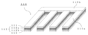
도 1 은, 본 발명의 제 1 실시형태에 관련된 전기 박리형 점착 시트 (110) (이하, 간단히 「본 실시형태의 점착 시트 (110)」 나 「점착 시트 (110)」라고도 한다) 의 개략도이다. 본 실시형태의 점착 시트 (110) 는, 적어도 일방의 면이 도전성을 갖는 통전용 기재 (112) 와, 통전용 기재 (112) 의 도전성을 갖는 면 상에 형성된 전기 박리용 점착제로 이루어지는 제 1 점착제층 (111) 과, 통전용 기재 (112) 의 제 1 점착제층 (111) 과는 반대 측의 면 상에 형성된 제 2 점착제층 (113) 을 구비하는 전기 박리형 점착 시트로서, 복수의 피연결부 (110a) 와, 복수의 피연결부 (110a) 끼리를 연결하는 연결부 (110b) 를 구비한다.1 is a schematic diagram of an electrically peelable pressure-sensitive
(점착 시트의 구성 요소) (Components of adhesive sheet)
먼저, 본 실시형태의 점착 시트 (110) 를 형성하는 각 층이나, 피연결부, 연결부에 대해 설명한다.First, each layer forming the pressure-sensitive
제 1 점착제층 (111) 은, 전기 박리용 점착제로 이루어지는 점착제층으로서, 점착제인 폴리머 및 전해질을 함유한다.The first pressure-sensitive adhesive layer 111 is a pressure-sensitive adhesive layer made of a pressure-sensitive adhesive for electrical peeling, and contains a polymer as a pressure-sensitive adhesive and an electrolyte.
제 1 점착제층 (111) 에 함유되는 폴리머로는, 예를 들어, 아크릴계 폴리머, 고무계 폴리머, 비닐알킬에테르계 폴리머, 실리콘계 폴리머, 폴리에스테르계 폴리머, 폴리아미드계 폴리머, 우레탄계 폴리머, 불소계 폴리머, 및 에폭시계 폴리머를 들 수 있다. 또, 제 1 점착제층 (111) 은 1 종류의 폴리머만을 함유해도 되고, 2 종류 이상의 폴리머를 함유해도 된다.As the polymer contained in the first adhesive layer 111, for example, an acrylic polymer, a rubber polymer, a vinyl alkyl ether polymer, a silicone polymer, a polyester polymer, a polyamide polymer, a urethane polymer, a fluorine polymer, and And epoxy-based polymers. Further, the first pressure-sensitive adhesive layer 111 may contain only one type of polymer, or may contain two or more types of polymers.
비용의 억제나 높은 생산성의 실현이라는 관점에서는, 아크릴계 폴리머를 함유하는 것이 바람직하다. 아크릴계 폴리머란, 아크릴산알킬에스테르 및/또는 메타크릴산알킬에스테르에서 유래하는 모노머 유닛을, 질량비로 가장 많은 주된 모노머 유닛으로서 포함하는 중합체이다. 이하에서는, 「(메트)아크릴」 로, 「아크릴」 및/또는 「메타크릴」을 나타낸다.It is preferable to contain an acrylic polymer from the viewpoint of reducing cost and realizing high productivity. The acrylic polymer is a polymer containing a monomer unit derived from an alkyl acrylate ester and/or an alkyl methacrylate ester as the main monomer unit with the largest mass ratio. Below, as "(meth)acrylic", "acrylic" and/or "methacryl" are shown.
제 1 점착제층 (111) 이 아크릴계 폴리머를 함유하는 경우, 당해 아크릴계 폴리머는, 탄소수 1 ∼ 14 의 알킬기를 갖는 (메트)아크릴산알킬에스테르에서 유래하는 모노머 유닛을 포함하는 것이 바람직하다. 당해 (메트)아크릴산알킬에스테르로는, 예를 들어, 메틸(메트)아크릴레이트, 에틸(메트)아크릴레이트, 프로필(메트)아크릴레이트, 이소프로필(메트)아크릴레이트, n-부틸(메트)아크릴레이트, sec-부틸(메트)아크릴레이트, 1,3-디메틸부틸아크릴레이트, 펜틸(메트)아크릴레이트, 이소펜틸(메트)아크릴레이트, 헥실(메트)아크릴레이트, 2-에틸부틸(메트)아크릴레이트, 헵틸(메트)아크릴레이트, n-옥틸(메트)아크릴레이트, 이소옥틸(메트)아크릴레이트, 2-에틸헥실(메트)아크릴레이트, n-노닐(메트)아크릴레이트, 이소노닐(메트)아크릴레이트, n-데실(메트)아크릴레이트, 이소데실(메트)아크릴레이트, n-도데실(메트)아크릴레이트, n-트리데실(메트)아크릴레이트, 및 n-테트라데실(메트)아크릴레이트를 들 수 있다. 이들 중, n-부틸(메트)아크릴레이트, sec-부틸(메트)아크릴레이트, n-옥틸(메트)아크릴레이트, 이소옥틸(메트)아크릴레이트, 2-에틸헥실(메트)아크릴레이트, n-노닐(메트)아크릴레이트, 및 이소노닐(메트)아크릴레이트가 바람직하다. 또, 1 종류의 (메트)아크릴산알킬에스테르를 사용해도 되고, 2 종류 이상의 (메트)아크릴산알킬에스테르를 사용해도 된다.When the first pressure-sensitive adhesive layer 111 contains an acrylic polymer, the acrylic polymer preferably contains a monomer unit derived from an alkyl (meth)acrylate having an alkyl group having 1 to 14 carbon atoms. As the alkyl (meth)acrylate ester, for example, methyl (meth)acrylate, ethyl (meth)acrylate, propyl (meth)acrylate, isopropyl (meth)acrylate, n-butyl (meth)acrylic Rate, sec-butyl (meth)acrylate, 1,3-dimethylbutylacrylate, pentyl (meth)acrylate, isopentyl (meth)acrylate, hexyl (meth)acrylate, 2-ethylbutyl (meth)acrylic Rate, heptyl (meth)acrylate, n-octyl (meth)acrylate, isooctyl (meth)acrylate, 2-ethylhexyl (meth)acrylate, n-nonyl (meth)acrylate, isononyl (meth) Acrylate, n-decyl (meth)acrylate, isodecyl (meth)acrylate, n-dodecyl (meth)acrylate, n-tridecyl (meth)acrylate, and n-tetradecyl (meth)acrylate Can be mentioned. Among these, n-butyl (meth)acrylate, sec-butyl (meth)acrylate, n-octyl (meth)acrylate, isooctyl (meth)acrylate, 2-ethylhexyl (meth)acrylate, n- Nonyl (meth)acrylate and isononyl (meth)acrylate are preferred. Moreover, one type of (meth)acrylate alkyl ester may be used, and two or more types of (meth)acrylate alkyl ester may be used.
아크릴계 폴리머에 있어서의, 탄소수 1 ∼ 14 의 알킬기를 갖는 (메트)아크릴산알킬에스테르에서 유래하는 모노머 유닛의 비율은, 제 1 점착제층 (111) 에 대해 높은 접착력을 실현한다는 관점에서는, 바람직하게는 50 질량% 이상, 보다 바람직하게는 60 질량% 이상, 보다 바람직하게는 70 질량% 이상, 보다 바람직하게는 80 질량% 이상이다. 즉, 아크릴계 폴리머를 형성하기 위한 원료 모노머의 총량에 있어서의, 탄소수 1 ∼ 14 의 알킬기를 갖는 (메트)아크릴산알킬에스테르의 비율은, 제 1 점착제층 (111) 에 대해 높은 접착력을 실현한다는 관점에서는, 바람직하게는 50 질량% 이상, 보다 바람직하게는 60 질량% 이상, 보다 바람직하게는 70 질량% 이상, 보다 바람직하게는 80 질량% 이상이다. In the acrylic polymer, the ratio of the monomer unit derived from the alkyl (meth)acrylate having an alkyl group having 1 to 14 carbon atoms is preferably 50 from the viewpoint of realizing high adhesion to the first pressure-sensitive adhesive layer 111. It is mass% or more, more preferably 60 mass% or more, more preferably 70 mass% or more, and more preferably 80 mass% or more. That is, the ratio of the (meth)acrylate alkyl ester having an alkyl group having 1 to 14 carbon atoms in the total amount of the raw material monomer for forming the acrylic polymer is from the viewpoint of realizing high adhesion to the first pressure-sensitive adhesive layer 111 , Preferably 50% by mass or more, more preferably 60% by mass or more, more preferably 70% by mass or more, and more preferably 80% by mass or more.
제 1 점착제층 (111) 이 아크릴계 폴리머를 함유하는 경우, 당해 아크릴계 폴리머는, 제 1 점착제층 (111) 에 대해 높은 접착력을 실현한다는 관점에서는, 극성기 함유 모노머에서 유래하는 모노머 유닛을 포함하는 것이 바람직하다. 극성기 함유 모노머로는, 예를 들어, 카르복실기 함유 모노머, 수산기 함유 모노머, 및 비닐기 함유 모노머를 들 수 있다.When the first pressure-sensitive adhesive layer 111 contains an acrylic polymer, the acrylic polymer preferably contains a monomer unit derived from a polar group-containing monomer from the viewpoint of realizing high adhesion to the first pressure-sensitive adhesive layer 111 Do. As a polar group-containing monomer, a carboxyl group-containing monomer, a hydroxyl group-containing monomer, and a vinyl group-containing monomer are mentioned, for example.
카르복실기 함유 모노머로는, 예를 들어, 아크릴산, 메타크릴산, 이타콘산, 말레산, 푸마르산, 크로톤산, 이소크로톤산, 카르복시에틸(메트)아크릴레이트, 및 카르복시펜틸(메트)아크릴레이트를 들 수 있다. 이들 중, 아크릴산 및 메타크릴산이 바람직하다. 또, 1 종류의 카르복실기 함유 모노머를 사용해도 되고, 2 종류 이상의 카르복실기 함유 모노머를 사용해도 된다.Examples of the carboxyl group-containing monomer include acrylic acid, methacrylic acid, itaconic acid, maleic acid, fumaric acid, crotonic acid, isocrotonic acid, carboxyethyl (meth)acrylate, and carboxypentyl (meth)acrylate. have. Among these, acrylic acid and methacrylic acid are preferred. Moreover, one type of carboxyl group-containing monomer may be used, and two or more types of carboxyl group-containing monomers may be used.
수산기 함유 모노머로는, 예를 들어, 2-하이드록시에틸(메트)아크릴레이트, 2-하이드록시프로필(메트)아크릴레이트, 4-하이드록시부틸(메트)아크릴레이트, 6-하이드록시헥실(메트)아크릴레이트, 8-하이드록시옥틸(메트)아크릴레이트, 10-하이드록시데실(메트)아크릴레이트, 12-하이드록시라우릴(메트)아크릴레이트, (4-하이드록시메틸시클로헥실)메틸아크릴레이트, N-메틸올(메트)아크릴아미드, 비닐알코올, 알릴알코올, 2-하이드록시에틸비닐에테르, 4-하이드록시부틸비닐에테르, 및 디에틸렌글리콜모노비닐에테르를 들 수 있다. 이들 중, 2-하이드록시에틸(메트)아크릴레이트가 바람직하다. 또, 1 종류의 수산기 함유 모노머를 사용해도 되고, 2 종류 이상의 수산기 함유 모노머를 사용해도 된다.As a hydroxyl-containing monomer, for example, 2-hydroxyethyl (meth)acrylate, 2-hydroxypropyl (meth)acrylate, 4-hydroxybutyl (meth)acrylate, and 6-hydroxyhexyl (meth)acrylate )Acrylate, 8-hydroxyoctyl (meth)acrylate, 10-hydroxydecyl (meth)acrylate, 12-hydroxylauryl (meth)acrylate, (4-hydroxymethylcyclohexyl)methylacrylate , N-methylol (meth)acrylamide, vinyl alcohol, allyl alcohol, 2-hydroxyethyl vinyl ether, 4-hydroxybutyl vinyl ether, and diethylene glycol monovinyl ether. Among these, 2-hydroxyethyl (meth)acrylate is preferable. Moreover, one type of hydroxyl group-containing monomer may be used, and two or more types of hydroxyl group-containing monomers may be used.
비닐기 함유 모노머로는, 예를 들어, 아세트산비닐, 프로피온산비닐, 및 라우르산비닐을 들 수 있다. 이들 중, 아세트산비닐이 바람직하다. 또, 1 종류의 비닐기 함유 모노머를 사용해도 되고, 2 종류 이상의 비닐기 함유 모노머를 사용해도 된다.As a vinyl group-containing monomer, vinyl acetate, vinyl propionate, and vinyl laurate are mentioned, for example. Among these, vinyl acetate is preferable. Moreover, one type of vinyl group-containing monomer may be used, and two or more types of vinyl group-containing monomers may be used.
상기 아크릴계 폴리머에 있어서의, 극성기 함유 모노머에서 유래하는 모노머 유닛의 비율은, 제 1 점착제층 (111) 에 있어서 응집력을 확보하여 제 1 점착제층 (111) 의 박리 후의 피착체 표면에서의 풀 잔류를 방지한다는 관점에서는, 바람직하게는 0.1 질량% 이상이다. 즉, 상기 아크릴계 폴리머를 형성하기 위한 원료 모노머의 총량에 있어서의 극성기 함유 모노머의 비율은, 응집력 확보 및 풀 잔류의 방지라는 관점에서는, 바람직하게는 0.1 질량% 이상이다. 또, 상기 아크릴계 폴리머에 있어서의, 극성기 함유 모노머에서 유래하는 모노머 유닛의 비율은, 탄소수 1 ∼ 14 의 알킬기를 갖는 상기 서술한 (메트)아크릴산알킬에스테르에서 유래하는 모노머 유닛에서 기인하는 특성을 아크릴계 폴리머에 있어서 적절히 발현시킨다는 관점에서는, 바람직하게는 30 질량% 이하이다. 즉, 상기 아크릴계 폴리머를 형성하기 위한 원료 모노머의 총량에 있어서의 극성기 함유 모노머의 비율은, 당해 특성의 발현이라는 관점에서는, 바람직하게는 30 질량% 이하이다.The ratio of the monomer units derived from the polar group-containing monomer in the acrylic polymer is to ensure the cohesive force in the first pressure-sensitive adhesive layer 111 so that the glue remains on the surface of the adherend after peeling of the first pressure-sensitive adhesive layer 111. From the viewpoint of preventing, it is preferably 0.1% by mass or more. In other words, the ratio of the polar group-containing monomer in the total amount of the raw material monomers for forming the acrylic polymer is preferably 0.1% by mass or more from the viewpoint of securing cohesive strength and preventing glue retention. In addition, the ratio of the monomer units derived from the polar group-containing monomer in the acrylic polymer is characterized by the properties derived from the monomer units derived from the above-described alkyl (meth)acrylate having an alkyl group having 1 to 14 carbon atoms. From the viewpoint of making it express appropriately, it is preferably 30 mass% or less. That is, the ratio of the polar group-containing monomer in the total amount of the raw material monomer for forming the acrylic polymer is preferably 30% by mass or less from the viewpoint of the expression of the characteristics.
상기와 같은 모노머를 중합하여 아크릴계 폴리머를 얻는 방법은 특별히 한정되지 않고, 공지된 방법을 사용할 수 있고, 중합 수법으로는, 예를 들어, 용액 중합, 유화 중합, 괴상 중합, 및 현탁 중합을 들 수 있다.The method of polymerizing the above-described monomers to obtain an acrylic polymer is not particularly limited, and a known method can be used, and examples of the polymerization method include solution polymerization, emulsion polymerization, bulk polymerization, and suspension polymerization. have.
제 1 점착제층 (111) 에 있어서의 폴리머의 함유량은, 제 1 점착제층 (111) 에 있어서 충분한 접착력을 실현한다는 관점에서, 바람직하게는 70 질량% 이상, 보다 바람직하게는 80 질량% 이상, 보다 바람직하게는 85 질량% 이상, 보다 바람직하게는 90 질량% 이상이다. The content of the polymer in the first pressure-sensitive adhesive layer 111 is preferably 70% by mass or more, more preferably 80% by mass or more, from the viewpoint of realizing sufficient adhesive force in the first pressure-sensitive adhesive layer 111. It is preferably 85% by mass or more, more preferably 90% by mass or more.
제 1 점착제층 (111) 에 함유되는 전해질은, 아니온과 카티온으로 전리 가능한 물질이며, 그러한 전해질로는, 이온 액체나, 알칼리 금속염, 알칼리 토금속염 등을 들 수 있다. 제 1 점착제층 (111) 에 있어서 양호한 전기 박리성을 실현한다는 관점에서는, 제 1 점착제층 (111) 에 함유되는 전해질로는, 이온 액체가 바람직하다. 이온 액체는, 실온 (약 25 ℃) 에서 액체의 염이고 아니온과 카티온을 포함한다.The electrolyte contained in the first pressure-sensitive adhesive layer 111 is a substance capable of ionizing with anions and cation, and examples of such electrolytes include ionic liquids, alkali metal salts, and alkaline earth metal salts. From the viewpoint of realizing good electrical releasability in the first pressure-sensitive adhesive layer 111, the electrolyte contained in the first pressure-sensitive adhesive layer 111 is preferably an ionic liquid. The ionic liquid is a salt of a liquid at room temperature (about 25° C.) and contains anions and cation.
제 1 점착제층 (111) 이 이온 액체를 함유하는 경우, 당해 이온 액체의 아니온은, (FSO2)2N-, (CF3SO2)2N-, (CF3CF2SO2)2N-, (CF3SO2)3C-, Br-, AlCl4 -, Al2Cl7 -, NO3 -, BF4 -, PF6 -, CH3COO-, CF3COO-, CF3CF2CF2COO-, CF3SO3 -, CF3(CF2)3SO3 -, AsF6 -, SbF6 - 및 F(HF)n - 로 이루어지는 군에서 선택되는 적어도 1 종을 함유하는 것이 바람직하다. 그 중에서도 아니온으로는, (FSO2)2N- [비스(플루오로술포닐)이미드 아니온], 및 (CF3SO2)2N- [비스(트리플루오로메탄술포닐)이미드 아니온] 가, 화학적으로 안정되어, 제 1 점착제층 (111) 의 전기 박리성을 실현하는 데 있어서 적합하므로 바람직하다.The first case of the pressure-sensitive adhesive layer (111) contains an ionic liquid anion of such ionic liquids, (FSO 2) 2 N - , (
제 1 점착제층 (111) 이 이온 액체를 함유하는 경우, 당해 이온 액체의 카티온은, 이미다졸륨계 카티온, 피리디늄계 카티온, 피롤리디늄계 카티온, 및 암모늄계 카티온으로 이루어지는 군에서 선택되는 적어도 1 종을 함유하는 것이 바람직하다.When the first pressure-sensitive adhesive layer 111 contains an ionic liquid, the cation of the ionic liquid is a group consisting of imidazolium-based cation, pyridinium-based cation, pyrrolidinium-based cation, and ammonium-based cation It is preferable to contain at least 1 type selected from.
이미다졸륨계 카티온으로는, 예를 들어, 1-메틸이미다졸륨 카티온, 1-에틸-3-메틸이미다졸륨 카티온, 1-프로필-3-메틸이미다졸륨 카티온, 1-부틸-3-메틸이미다졸륨 카티온, 1-펜틸-3-메틸이미다졸륨 카티온, 1-헥실-3-메틸이미다졸륨 카티온, 1-헵틸-3-메틸이미다졸륨 카티온, 1-옥틸-3-메틸이미다졸륨 카티온, 1-노닐-3-메틸이미다졸륨 카티온, 1-운데실-3-메틸이미다졸륨 카티온, 1-도데실-3-메틸이미다졸륨 카티온, 1-트리데실-3-메틸이미다졸륨 카티온, 1-테트라데실-3-메틸이미다졸륨 카티온, 1-펜타데실-3-메틸이미다졸륨 카티온, 1-헥사데실-3-메틸이미다졸륨 카티온, 1-헵타데실-3-메틸이미다졸륨 카티온, 1-옥타데실-3-메틸이미다졸륨 카티온, 1-운데실-3-메틸이미다졸륨 카티온, 1-벤질-3-메틸이미다졸륨 카티온, 1-부틸-2,3-디메틸이미다졸륨 카티온, 및 1,3-비스(도데실)이미다졸륨 카티온을 들 수 있다.Examples of the imidazolium cation include 1-methylimidazolium cation, 1-ethyl-3-methylimidazolium cation, 1-propyl-3-methylimidazolium cation, and 1-butyl -3-Methylimidazolium cation, 1-pentyl-3-methylimidazolium cation, 1-hexyl-3-methylimidazolium cation, 1-heptyl-3-methylimidazolium cation, 1 -Octyl-3-methylimidazolium cation, 1-nonyl-3-methylimidazolium cation, 1-undecyl-3-methylimidazolium cation, 1-dodecyl-3-methylimidazolium Cathione, 1-tridecyl-3-methylimidazolium cation, 1-tetradecyl-3-methylimidazolium cation, 1-pentadecyl-3-methylimidazolium cation, 1-hexadecyl- 3-methylimidazolium cation, 1-heptadecyl-3-methylimidazolium cation, 1-octadecyl-3-methylimidazolium cation, 1-undecyl-3-methylimidazolium cation , 1-benzyl-3-methylimidazolium cation, 1-butyl-2,3-dimethylimidazolium cation, and 1,3-bis(dodecyl)imidazolium cation.
피리디늄계 카티온으로는, 예를 들어, 1-부틸피리디늄 카티온, 1-헥실피리디늄 카티온, 1-부틸-3-메틸피리디늄 카티온, 1-부틸-4-메틸피리디늄 카티온, 및 1-옥틸-4-메틸피리디늄 카티온을 들 수 있다.As a pyridinium-based cation, for example, 1-butylpyridinium cation, 1-hexylpyridinium cation, 1-butyl-3-methylpyridinium cation, and 1-butyl-4-methylpyridinium Cation and 1-octyl-4-methylpyridinium cation.
피롤리디늄계 카티온으로는, 예를 들어, 1-에틸-1-메틸피롤리디늄 카티온 및 1-부틸-1-메틸피롤리디늄 카티온을 들 수 있다.Examples of the pyrrolidinium-based cation include 1-ethyl-1-methylpyrrolidinium cation and 1-butyl-1-methylpyrrolidinium cation.
암모늄계 카티온으로는, 예를 들어, 테트라에틸암모늄 카티온, 테트라부틸암모늄 카티온, 메틸트리옥틸암모늄 카티온, 테트라데시트리헥실암모늄 카티온, 글리시딜트리메틸암모늄 카티온, 및 트리메틸아미노에틸아크릴레이트 카티온을 들 수 있다.Examples of ammonium-based cation include tetraethylammonium cation, tetrabutylammonium cation, methyltrioctylammonium cation, tetradecytrihexylammonium cation, glycidyltrimethylammonium cation, and trimethylaminoethyl Acrylate cation.
제 1 점착제층 (111) 중의 이온 액체로는, 카티온에 대한 높은 확산성을 이용하여 제 1 점착제층 (111) 에 있어서 높은 전기 박리성을 실현한다는 관점에서, 상기 (FSO2)2N- [비스(플루오로술포닐)이미드 아니온] 와 분자량 160 이하의 카티온을 포함하는 이온 액체가 특히 바람직하다. 분자량 160 이하의 카티온으로는, 예를 들어, 1-메틸이미다졸륨 카티온, 1-에틸-3-메틸이미다졸륨 카티온, 1-프로필-3-메틸이미다졸륨 카티온, 1-부틸-3-메틸이미다졸륨 카티온, 1-펜틸-3-메틸이미다졸륨 카티온, 1-부틸피리디늄 카티온, 1-헥실피리디늄 카티온, 1-부틸-3-메틸피리디늄 카티온, 1-부틸-4-메틸피리디늄 카티온, 1-에틸-1-메틸피롤리디늄 카티온, 1-부틸-1-메틸피롤리디늄 카티온, 테트라에틸암모늄 카티온, 글리시딜트리메틸암모늄 카티온, 및 트리메틸아미노에틸아크릴레이트 카티온을 들 수 있다. As the ionic liquid in the first pressure-sensitive adhesive layer 111, from the viewpoint of realizing high electrical peelability in the first pressure-sensitive adhesive layer 111 by using high diffusibility to cation, the (FSO 2 ) 2 N- An ionic liquid containing [bis(fluorosulfonyl)imide anion] and a cation having a molecular weight of 160 or less is particularly preferable. As a cation having a molecular weight of 160 or less, for example, 1-methylimidazolium cation, 1-ethyl-3-methylimidazolium cation, 1-propyl-3-methylimidazolium cation, 1- Butyl-3-methylimidazolium cation, 1-pentyl-3-methylimidazolium cation, 1-butylpyridinium cation, 1-hexylpyridinium cation, 1-butyl-3-methylpyridinium Cathione, 1-butyl-4-methylpyridinium cation, 1-ethyl-1-methylpyrrolidinium cation, 1-butyl-1-methylpyrrolidinium cation, tetraethylammonium cation, glycidyl Trimethylammonium cation, and trimethylaminoethylacrylate cation.
제 1 점착제층 (111) 에 함유되는 이온 액체의 시판품으로는, 예를 들어, 다이이치 공업 제약 주식회사 제조의 「엘렉셀 AS-110」, 「엘렉셀 MP-442」, 「엘렉셀 IL-210」, 「엘렉셀 MP-471」, 「엘렉셀 MP-456」, 및 「엘렉셀 AS-804」를 들 수 있다.As a commercial item of the ionic liquid contained in the 1st adhesive layer 111, Daiichi Kogyo Pharmaceutical Co., Ltd. "Elexel AS-110", "Elexel MP-442", "Elexel IL-210" ", "Elexel MP-471", "Elexel MP-456", and "Elexel AS-804".
알칼리 금속염으로는, 예를 들어, LiCl, Li2SO4, LiBF4, LiPF6, LiClO4, LiAsF6, LiCF3SO3, LiN(SO2CF3)2, LiN(SO2C2F5)2, LiC(SO2CF3)3, NaCl, Na2SO4, NaBF4, NaPF6, NaClO4, NaAsF6, NaCF3SO3, NaN(SO2CF3)2, NaN(SO2C2F5)2, NaC(SO2CF3)3, KCl, K2SO4, KBF4, KPF6, KClO4, KAsF6, KCF3SO3, KN(SO2CF3)2, KN(SO2C2F5)2 및 KC(SO2CF3)3 을 들 수 있다. As an alkali metal salt, for example, LiCl, Li 2 SO 4 , LiBF 4 , LiPF 6 , LiClO 4 , LiAsF 6 , LiCF 3 SO 3 , LiN(SO 2 CF 3 ) 2 , LiN(SO 2 C 2 F 5 ) 2 , LiC(SO 2 CF 3 ) 3 , NaCl, Na 2 SO 4 , NaBF 4 , NaPF 6 , NaClO 4 , NaAsF6, NaCF 3 SO 3 , NaN(SO 2 CF 3 ) 2 , NaN(SO 2 C 2 F 5 ) 2 , NaC(SO 2 CF 3 ) 3 , KCl, K2SO 4 , KBF 4 , KPF 6 , KClO 4 , KAsF 6 , KCF 3 SO 3 , KN(SO 2 CF 3 ) 2 , KN(SO 2 C 2 F 5 ) 2 and KC(SO 2 CF 3 ) 3 .
제 1 점착제층 (111) 에 있어서의 이온 액체의 함유량은, 제 1 점착제층 (111) 에 있어서 전기 박리성을 부여하기 위해서 예를 들어 제 1 점착제층 (111) 내의 폴리머 100 질량부에 대해, 0.1 질량부 이상이며, 보다 양호한 전기 박리성을 실현한다는 관점에서는, 바람직하게는 0.5 질량부 이상, 보다 바람직하게는 0.6 질량부 이상, 더욱 바람직하게는 0.8 질량부 이상, 특히 바람직하게는 1.0 질량부 이상, 가장 바람직하게는 1.5 질량부 이상이다. 제 1 점착제층 (111) 에 대해 양호한 접착력과 전기 박리성을 밸런스 양호하게 실현한다는 관점에서는, 제 1 점착제층 (111) 에 있어서의 이온 액체의 함유량은, 제 1 점착제층 (111) 내의 폴리머 100 질량부에 대해, 바람직하게는 30 질량부 이하, 보다 바람직하게는 20 질량부 이하, 더욱 바람직하게는 15 질량부 이하, 특히 바람직하게는 10 질량부 이하, 가장 바람직하게는 5 질량부 이하이다.The content of the ionic liquid in the first pressure-sensitive adhesive layer 111 is, for example, relative to 100 parts by mass of the polymer in the first pressure-sensitive adhesive layer 111 in order to impart electrical releasability in the first pressure-sensitive adhesive layer 111, 0.1 parts by mass or more, preferably 0.5 parts by mass or more, more preferably 0.6 parts by mass or more, still more preferably 0.8 parts by mass or more, particularly preferably 1.0 parts by mass from the viewpoint of realizing better electrical peelability Or more, most preferably 1.5 parts by mass or more. From the viewpoint of realizing a good balance between good adhesion and electrical peelability to the first pressure-sensitive adhesive layer 111, the content of the ionic liquid in the first pressure-sensitive adhesive layer 111 is the polymer 100 in the first pressure-sensitive adhesive layer 111 It is preferably 30 parts by mass or less, more preferably 20 parts by mass or less, still more preferably 15 parts by mass or less, particularly preferably 10 parts by mass or less, and most preferably 5 parts by mass or less based on parts by mass.
제 1 점착제층 (111) 은, 본 발명의 효과를 저해하지 않는 범위에서, 기타 성분을 함유하고 있어도 된다. 그러한 성분으로는, 예를 들어, 점착 부여제, 실란 커플링제, 착색제, 안료, 염료, 표면 윤활제, 레벨링제, 연화제, 산화 방지제, 노화 방지제, 광 안정제, 중합 금지제, 무기 또는 유기의 충전제, 금속 분말, 입자상물, 및 박상물 (箔狀物) 을 들 수 있다. 이들 성분의 함유량은, 사용 목적에 따라 본 발명의 효과를 저해하지 않는 범위에 있어서 결정된다. 예를 들어, 폴리머 100 질량부에 대해 예를 들어 10 질량부 이하이다.The first adhesive layer 111 may contain other components within a range not impairing the effects of the present invention. Such components include, for example, tackifiers, silane coupling agents, colorants, pigments, dyes, surface lubricants, leveling agents, softeners, antioxidants, anti-aging agents, light stabilizers, polymerization inhibitors, inorganic or organic fillers, Metal powder, particulate matter, and thin material are mentioned. The content of these components is determined within a range that does not impair the effects of the present invention depending on the intended use. For example, it is 10 mass parts or less with respect to 100 mass parts of a polymer, for example.
제 1 점착제층 (111) 의 두께는 특별히 한정되지 않지만, 제 1 점착제층 (111) 에 있어서 양호한 점착성을 실현한다는 관점에서, 바람직하게는 1 ㎛ 이상, 보다 바람직하게는 3 ㎛ 이상, 더욱 바람직하게는 5 ㎛ 이상, 특히 바람직하게는 8 ㎛ 이상이다. 또, 피착체 박리 시의 인가 전압을 저감한다는 관점에서, 바람직하게는 1000 ㎛ 이하, 보다 바람직하게는 500 ㎛ 이하, 더욱 바람직하게는 100 ㎛ 이하, 특히 바람직하게는 30 ㎛ 이하이다. The thickness of the first pressure-sensitive adhesive layer 111 is not particularly limited, but from the viewpoint of realizing good adhesion in the first pressure-sensitive adhesive layer 111, it is preferably 1 μm or more, more preferably 3 μm or more, and even more preferably Is 5 μm or more, particularly preferably 8 μm or more. In addition, from the viewpoint of reducing the applied voltage during peeling of the adherend, it is preferably 1000 µm or less, more preferably 500 µm or less, still more preferably 100 µm or less, and particularly preferably 30 µm or less.
제 2 점착제층 (113) 은, 제 2 점착제층 (113) 에서 점착성을 발현시키기 위한 폴리머를 함유한다. 제 2 점착제층 (113) 에 함유되는 성분과 그 함유량에 대해서는, 전해질의 점을 제외하고, 제 1 점착제층 (111) 에 함유되는 성분과 그 함유량에 관해서 상기 서술한 것과 동일하다.The second adhesive layer 113 contains a polymer for expressing adhesiveness in the second adhesive layer 113. The components contained in the second pressure-sensitive adhesive layer 113 and their content are the same as those described above with respect to the components contained in the first pressure-sensitive adhesive layer 111 and their content, excluding the point of the electrolyte.
제 2 점착제층 (113) 의 두께는 특별히 한정되지 않지만, 제 2 점착제층 (113) 에 있어서 양호한 점착성을 실현한다는 관점에서, 바람직하게는 1 ㎛ 이상, 보다 바람직하게는 3 ㎛ 이상, 더욱 바람직하게는 5 ㎛ 이상, 특히 바람직하게는 8㎛ 이상이다. 또, 바람직하게는 1000 ㎛ 이하, 보다 바람직하게는 500 ㎛ 이하, 더욱 바람직하게는 100 ㎛ 이하이다. The thickness of the second pressure-sensitive adhesive layer 113 is not particularly limited, but from the viewpoint of realizing good adhesion in the second pressure-sensitive adhesive layer 113, it is preferably 1 µm or more, more preferably 3 µm or more, and even more preferably Is 5 μm or more, particularly preferably 8 μm or more. Further, it is preferably 1000 µm or less, more preferably 500 µm or less, and still more preferably 100 µm or less.
통전용 기재 (112) 는, 적어도 편방의 면에 있어서 도전성을 갖는 한 특별히 한정은 되지 않는다. 예를 들어 도 1 에 나타내는 바와 같이 도전층 (112a) 과 기재층 (112b) 을 포함하는 적층 구조여도 되고, 금속박 등으로 이루어지는 단상 구조여도 된다.The
통전용 기재 (112) 의 두께는 특별히 한정되지 않지만, 10 ㎛ 이상인 것이 바람직하고, 12 ㎛ 이상인 것이 보다 바람직하고, 25 ㎛ 이상인 것이 더욱 바람직하다. 또, 1000 ㎛ 이하인 것이 바람직하고, 500 ㎛ 이하인 것이 보다 바람직하고, 300 ㎛ 이하인 것이 더욱 바람직하고, 100 ㎛ 이하인 것이 특히 바람직하다.The thickness of the energizing
통전용 기재 (112) 가 도전층 (112a) 과 기재층 (112b) 을 포함하는 적층 구조인 경우, 기재층 (112b) 은, 지지체로서 기능하는 부위이며, 예를 들어, 플라스틱계 기재, 섬유계 기재, 또는 종이계 기재, 이들의 적층체 등을 들 수 있다. 기재층 (112b) 은 단층이어도 되고 복층이어도 된다. 또, 기재층 (112b) 에는, 필요에 따라, 배면 처리, 대전 방지 처리, 하도 처리 등의 각종 처리가 실시되어 있어도 된다.When the
기재층 (112b) 의 두께는 특별히 한정되지 않지만, 10 ㎛ 이상인 것이 바람직하고, 12 ㎛ 이상인 것이 보다 바람직하고, 25 ㎛ 이상인 것이 더욱 바람직하다. 또, 기재층 (112b) 의 두께는 1000 ㎛ 이하인 것이 바람직하고, 500 ㎛ 이하인 것이 보다 바람직하고, 300 ㎛ 이하인 것이 더욱 바람직하고, 100 ㎛ 이하인 것이 특히 바람직하다.The thickness of the base layer 112b is not particularly limited, but it is preferably 10 µm or more, more preferably 12 µm or more, and even more preferably 25 µm or more. Further, the thickness of the base layer 112b is preferably 1000 µm or less, more preferably 500 µm or less, still more preferably 300 µm or less, and particularly preferably 100 µm or less.
도전층 (112a) 은, 도전성을 갖는 층이며, 예를 들어, 금속이나 도전성 폴리머로 이루어진다. 이와 같은 도전층 (112a) 은, 도금법, 화학 증착법, 또는 스퍼터링법 등에 의해 형성할 수 있다.The conductive layer 112a is a layer having conductivity, and is made of, for example, a metal or a conductive polymer. Such a conductive layer 112a can be formed by a plating method, a chemical vapor deposition method, a sputtering method, or the like.
도전층 (112a) 의 두께는 특별히 한정되지 않지만, 0.001 ㎛ 이상인 것이 바람직하고, 0.01 ㎛ 이상인 것이 보다 바람직하고, 0.03 ㎛ 이상인 것이 더욱 바람직하고, 0.05 ㎛ 이상인 것이 특히 바람직하다. 도전층 (112a) 의 두께는 또, 1000 ㎛ 이하인 것이 바람직하고, 500 ㎛ 이하인 것이 보다 바람직하고, 300 ㎛ 이하인 것이 더욱 바람직하고, 50 ㎛ 이하인 것이 특히 바람직하고, 10 ㎛ 이하인 것이 가장 바람직하다.The thickness of the conductive layer 112a is not particularly limited, but it is preferably 0.001 µm or more, more preferably 0.01 µm or more, still more preferably 0.03 µm or more, and particularly preferably 0.05 µm or more. The thickness of the conductive layer 112a is also preferably 1000 µm or less, more preferably 500 µm or less, still more preferably 300 µm or less, particularly preferably 50 µm or less, and most preferably 10 µm or less.
본 실시형태의 점착 시트 (110) 는, 복수의 피연결부 (110a) 를 구비한다. 피연결부 (110a) 의 크기나 형상은 특별히 한정되지 않고, 피연결부 (110a) 마다 상이해도 되고, 동일해도 된다. 또, 피연결부 (110a) 의 개수도 특별히 한정되는 것은 아니다. The pressure-
또, 복수의 피연결부 (110a) 는 연결부 (110b) 에 의해 연결되어 있다. 연결부 (110b) 의 크기나 형상도 특별히 한정되지 않고, 연결부 (110b) 마다 상이해도 되고, 동일해도 된다. 또, 개수도 특별히 한정되지 않는다. 본 실시형태의 점착 시트 (110) 에 있어서, 모든 피연결부 (110a) 는, 적어도 1 개의 다른 피연결부 (110a) 와 연결부 (110b) 에 의해 연결되어 있다.Further, the plurality of connected portions 110a are connected by a connecting
상기와 같은 본 실시형태의 점착 시트 (110) 는, 균일한 점착 시트와 비교해 각각의 피연결부 (110a) 및 연결부 (110b) 의 면적이 작기 때문에, 첩부 (貼付) 시의 기포의 혼입을 억제할 수 있다. 또, 복수의 피연결부 (110a) 간에 간극이 존재하기 때문에, 피착체 표면의 요철 등이 당해 간극에 위치하도록 하여 피착체의 접합을 실시할 수 있다.The pressure-
또한, 균일한 점착 시트와 비교해 본 실시형태의 점착 시트 (110) 는 면적이 작기 때문에, 비용 삭감의 관점에서도 바람직하다. In addition, since the area of the pressure-
또한, 본 실시형태의 점착 시트 (110) 의 제 1 점착제층 (111) 및 제 2 점착제층 (113) 의 표면에는, 세퍼레이터 (박리 라이너) 가 형성되어 있어도 된다. 세퍼레이터는, 점착 시트 (110) 의 제 1 점착제층 (111) 및 제 2 점착제층 (113) 이 노출되지 않도록 보호하기 위한 요소이며, 점착 시트 (110) 를 피착체에 첩부할 때에 점착 시트 (110) 로부터 박리된다. 2 장의 세퍼레이터에 의해 점착 시트 (110) 가 사이에 두어지는 형태를 취해도 되고, 점착 시트 (110) 와 세퍼레이터가 교대로 배치되도록 점착 시트 (110) 가 세퍼레이터를 수반하여 롤상으로 권회된 형태를 취해도 된다. 세퍼레이터로는, 예를 들어, 박리 처리층을 갖는 기재, 불소 폴리머로 이루어지는 저접착성 기재, 및, 무극성 폴리머로 이루어지는 저접착성 기재를 들 수 있다. 세퍼레이터의 표면은, 이형 처리, 방오 처리, 또는 대전 방지 처리가 실시되어 있어도 된다. 세퍼레이터의 두께는, 예를 들어 5 ∼ 200 ㎛ 이다. In addition, a separator (release liner) may be formed on the surfaces of the first adhesive layer 111 and the second adhesive layer 113 of the
(점착 시트의 접착력) (Adhesion of adhesive sheet)
점착 시트 (110) 의 각 점착면, 즉, 제 1 점착제층 (111) 측의 표면 및 제 2 점착제층 (113) 측의 표면에 대해서는, 양호한 접착력을 실현한다는 관점에서, 그 180°박리 점착력 (SUS304 판에 대해, 인장 속도 300 mm/분, 박리 온도 23 ℃) 이 0.1 N/10 mm 이상인 것이 바람직하다. 점착 시트 (110) 의 180°박리 점착력에 대해서는, 예를 들어 이하와 같이 해, JIS Z 0237 에 준해 측정할 수 있다.For each adhesive surface of the
먼저, 양면에 세퍼레이터를 수반하는 점착 시트 (110) 에 대해, 일방의 세퍼레이터를 박리한 후, 노출된 점착면에 두께 50 ㎛ 의 폴리에틸렌테레프탈레이트 (PET) 필름에 첩부하여, 점착 시트 (110) 를 배접한다. 다음으로, 이 배접된 점착 시트 (110) 로부터 시험편 (폭 10 mm × 길이 100 mm) 을 잘라낸다. 다음으로, 이 시험편으로부터 타방의 세퍼레이터를 박리하고, 시험편을 피착체인 스테인리스판 (SUS304) 에 첩합 (貼合) 한 후, 2 kg 의 롤러를 1 왕복시킴으로써 시험편과 피착체를 압착시킨다. 그리고, 30 분간 정치한 후, 박리 시험기 (상품명 「변각 필 측정기 YSP」, 아사히 정공 주식회사 제조) 를 사용하여, 180°박리 점착력 (인장 속도 : 300 mm/분, 박리 온도 23 ℃) 을 측정한다.First, with respect to the pressure-
(점착 시트의 제조 방법) (Method of manufacturing adhesive sheet)
점착 시트의 제조에 있어서는, 예를 들어, 먼저, 제 1 점착제층을 형성하기 위한 점착제 조성물 (제 1 조성물), 및, 제 2 점착제층을 형성하기 위한 점착제 조성물 (제 2 조성물) 을, 각각 제조한다. 다음으로, 제 1 조성물을 통전용 기재의 도전성을 갖는 면에 도포하여 이것을 건조시킨다. 이로써 제 1 점착제층이 형성된다. 다음으로, 제 2 조성물을 통전용 기재의 반대 측에 도포하여 이것을 건조시킨다. 이로써 제 2 점착제층이 형성된다. 예를 들어 이와 같이 하여, 점착 시트를 제조할 수 있다.In the production of the pressure-sensitive adhesive sheet, for example, first, a pressure-sensitive adhesive composition (first composition) for forming a first pressure-sensitive adhesive layer, and a pressure-sensitive adhesive composition (second composition) for forming a second pressure-sensitive adhesive layer, respectively do. Next, the first composition is applied to the conductive surface of a substrate for electric current and dried. As a result, the first pressure-sensitive adhesive layer is formed. Next, the second composition is applied to the opposite side of the energized substrate and dried. As a result, a second pressure-sensitive adhesive layer is formed. For example, in this way, an adhesive sheet can be manufactured.
혹은, 이른바 전사법에 의해 점착 시트를 제조해도 된다. 구체적으로는, 먼저, 제 1 점착제층 및 제 2 점착제층을 각각 세퍼레이터 (박리 라이너) 상에 형성한다. 제 1 점착제층에 대해서는, 제 1 점착제층 형성용의 상기 제 1 조성물을 소정의 세퍼레이터의 박리 처리면에 도포하여 도막을 형성한 후, 당해 도막을 건조시켜 형성한다. 제 2 점착제층에 대해서는, 제 2 점착제층 형성용의 상기 제 2 조성물을 소정의 세퍼레이터의 박리 처리면에 도포하여 도막을 형성한 후, 당해 도막을 건조시켜 형성한다. 다음으로, 세퍼레이터를 수반하는 제 1 점착제층을 통전용 기재의 도전층의 측에 첩합한다. 다음으로, 세퍼레이터를 수반하는 제 2 점착제층을 통전용 기재의 기재층의 측에 첩합한다. 예를 들어 이와 같이 하여, 점착 시트를 제조할 수 있다.Alternatively, an adhesive sheet may be produced by a so-called transfer method. Specifically, first, a first adhesive layer and a second adhesive layer are formed on a separator (release liner), respectively. With respect to the first pressure-sensitive adhesive layer, the first composition for forming the first pressure-sensitive adhesive layer is applied to the peeling-treated surface of a predetermined separator to form a coating film, and then the coating film is dried. With respect to the second pressure-sensitive adhesive layer, the second composition for forming the second pressure-sensitive adhesive layer is applied to the peeling-treated surface of a predetermined separator to form a coating film, and then the coating film is dried. Next, the first pressure-sensitive adhesive layer accompanying the separator is bonded to the side of the conductive layer of the substrate for energization. Next, the second pressure-sensitive adhesive layer accompanying the separator is bonded to the side of the substrate layer of the substrate for energization. For example, in this way, an adhesive sheet can be manufactured.
점착 시트 (110) 를 제조할 때에는, 제조하는 점착 시트 (110) 와 동일한 형상 (이하, 「원하는 형상」이라고도 한다) 의 통전용 기재 (112) 를 사용하여 상기 방법으로 점착 시트 (110) 를 제조해도 되고, 원하는 형상과는 상이한 형상의 통전용 기재를 사용하여 상기 방법으로 제조한 점착 시트 (이하, 「점착 시트재」라고도 한다) 를 절단하여 원하는 형상으로 함으로써 점착 시트 (110) 를 제조해도 된다. When manufacturing the pressure-
점착 시트재를 절단하여 점착 시트 (110) 를 제조하는 경우에는, 점착 시트 (110) 의 형상은, 단일의 연결부 (110b) 로부터 복수의 피연결부 (110a) 가 연장되는 형상으로 하는 것이 바람직하고, 단일의 연결부 (110b) 로부터 복수의 피연결부 (110a) 가 동일 방향으로 연장되는 형상, 즉 복수의 도 1 에 나타내는 바와 같은 즐형으로 하는 것이 바람직하다. 이와 같은 경우에는, 2 개의 즐형의 점착 시트 (110) 가 맞물린 듯한 형태로 얻어지도록 점착 시트재를 절단하여 점착 시트 (110) 를 제조함으로써, 점착 시트재의 폐기 부분을 줄일 수 있어, 점착 시트 (110) 의 제조 비용을 감소시킬 수 있기 때문이다.In the case of manufacturing the pressure-
<접합체, 접합체의 전기 박리 방법> <Conjugate, electrical peeling method of the bonded body>
(접합체) (Conjugate)
다음으로, 제 1 실시형태의 점착 시트 (110) 를 사용하여 얻어지는 접합체에 대해 설명한다.Next, a bonded body obtained using the pressure-
도 2(a) 는, 본 발명의 제 1 실시형태에 관련된 접합체 (140) (이하, 간단히 「본 실시형태의 접합체 (140)」 나 「접합체 (140)」라고도 한다) 의 측면도이며, 도 2(b) 는 본 실시형태의 접합체 (140) 의 사시도이다. 도 3 은, 본 실시형태의 접합체 (140) 의 분해 사시도이다.Fig. 2(a) is a side view of a conjugate 140 according to the first embodiment of the present invention (hereinafter, also simply referred to as ``conjugate 140 of this embodiment'' or ``conjugate 140''), and Fig. 2 (b) is a perspective view of the joined
본 실시형태의 접합체 (140) 는, 본 실시형태의 점착 시트 (110) 와, 제 1 점착제층 (111) 에 첩착된 제 1 피착체 (120) 와, 제 2 점착제층 (113) 에 첩착된 제 2 피착체 (130) 를 구비하는 접합체이고, 제 1 피착체 (120) 는 도전성이다.The
제 1 피착체 (120) 는 도전성을 가지면 특별히 한정되지 않고, 이와 같은 피착체의 구성 재료로는, 예를 들어, 알루미늄, 구리, 철, 은, 및, 이들을 함유하는 합금을 들 수 있다. 또, 도전성 폴리머 등이어도 된다. 또한, 도전성은 적어도 본 발명의 효과를 발휘하기 위해 필요한 부분에 있어서 있으면 되고, 제 1 피착체 (120) 에 있어서는, 적어도 제 1 점착제층 (111) 과 접촉하는 부분, 및 전압 인가 디바이스의 단자를 접촉시키는 부분에 있어서 도전성이 있고, 이들 부분이 도통하고 있으면 된다. 한편, 본 실시형태에 있어서 제 2 피착체 (130) 는 도전성을 가지고 있어도 되고, 가지고 있지 않아도 된다.The
(전기 박리 방법) (Electric peeling method)
상기와 같은 구성의 접합체 (140) 의 전기 박리 시에는, 점착 시트 (110) 의 제 1 점착제층 (111) 에 대해, 제 1 피착체 (120) 와 통전용 기재 (112) 를 개재하여 전압을 인가한다. 본 실시형태의 접합체 (140) 를 접합하는 점착 시트 (110) 에 있어서는, 복수의 피연결부 (110a) 가 각각 연결부 (110b) 에 의해 연결되어 있기 때문에, 모든 피연결부 (110a), 및 연결부 (110b) 에 대해, 동시에 전압을 인가하는 것이 용이하다.In the case of electrical peeling of the bonded
또한, 전압 인가 시에 단자를 제 1 피착체 (120) 및 통전용 기재 (112) 에 접촉시키는 방법은 특별히 한정되지 않지만, 제 1 피착체 (120) 및 통전용 기재 (112) 에 대해, 동일한 방향으로부터 각각 전압 인가 디바이스의 단자를 접촉시키는 것이, 작업성의 관점에서 특히 바람직하다.In addition, the method of bringing the terminal into contact with the
예를 들어 제 1 피착체의 방향으로부터 제 1 피착체 (120) 및 통전용 기재 (112) 에 단자를 접촉시키는 경우, 통전용 기재 (112) 에 대한 전압 인가 디바이스의 단자의 접촉을 용이하게 하기 위해서, 점착 시트 (110) 는, 접합체 (140) 를 제 1 피착체 (120) 의 방향으로부터 평면에서 보아 관찰했을 때에 제 1 피착체 (120) 로부터 돌출되는 부분을 구비해도 된다. 이 부분은 제 1 점착제층 (111) 을 구비해도 되고, 제 1 점착제층 (111) 을 구비하지 않고 통전용 기재 (112) 의 도전성을 갖는 면이 노출되어 있어도 된다. 이와 같은 부분을 구비함으로써, 통전용 기재 (112) 에 제 1 피착체 (120) 의 방향으로부터 전압 인가 디바이스의 단자를 접촉시키는 것이 용이해진다. 또한, 이와 같은 부분이 제 1 점착제층 (111) 을 구비하는 경우에는, 단자를, 제 1 점착제층 (111) 을 관통시켜 통전용 기재에 접촉시킨다.For example, when a terminal is brought into contact with the
또, 예를 들어 제 1 피착체 (120) 및 제 1 점착제층 (111) 을 관통시켜 단자를 통전용 기재 (112) 에 접촉시켜도 된다.Further, for example, the
접합체 (140) 의 전기 박리 시의 제 1 점착제층 (111) 에 대한 인가 전압은, 1 V 이상인 것이 바람직하고, 3 V 이상인 것이 보다 바람직하고, 6 V 이상인 것이 더욱 바람직하다. 또, 100 V 이하인 것이 바람직하고, 50 V 이하인 것이 보다 바람직하고, 30 V 이하인 것이 더욱 바람직하고, 15 V 이하인 것이 특히 바람직하다. 이와 같은 범위 내이면, 접합체의 분리 작업을 효율적으로 실시할 수 있기 때문에, 바람직하다. 예를 들어, 이와 같은 범위 내이면, 전압 인가 디바이스의 전원으로서 건전지 등 입수하기 쉬운 것을 사용하는 것이 가능하다.The voltage applied to the first pressure-sensitive adhesive layer 111 at the time of electrical peeling of the bonded
또, 제 1 점착제층 (111) 에 대한 전압의 인가 시간은 짧은 것이 바람직하고, 구체적으로는, 바람직하게는 60 초 이내, 보다 바람직하게는 40 초 이내, 보다 바람직하게는 20 초 이내이다. 이와 같은 범위 내이면, 접합체의 분리 작업의 효율화를 도모하는 데 있어서 바람직하다.Further, the application time of the voltage to the first pressure-sensitive adhesive layer 111 is preferably short, specifically, preferably within 60 seconds, more preferably within 40 seconds, and more preferably within 20 seconds. When it is within such a range, it is preferable to improve the efficiency of the separation operation of the bonded body.
이들 바람직한 인가 전압이나 바람직한 인가 시간에 대해서는, 후술하는 제 2 ∼ 5 의 실시형태에 있어서도 동일하다.These preferred applied voltages and preferred applied times are also the same in the second to fifth embodiments described later.
[제 2 실시형태] [Second Embodiment]
도 4(a) 는, 본 발명의 제 2 실시형태에 관련된 접합체 (240) (이하, 간단히 「본 실시형태의 접합체 (240)」 나 「접합체 (240)」 라고도 한다) 의 측면도이며, 도 4(b) 는 본 실시형태의 접합체 (240) 의 사시도이다. 도 5 는, 본 실시형태의 접합체 (240) 의 분해 사시도이다. Fig. 4(a) is a side view of a conjugate 240 according to a second embodiment of the present invention (hereinafter, also simply referred to as “conjugate 240 of this embodiment” and “conjugate 240”), and FIG. 4 (b) is a perspective view of the joined
본 실시형태의 접합체 (240) 는, 제 1 피착체 (220) 와 제 2 피착체 (230) 가 복수의 전기 박리형 점착 시트 (210) 에 의해 접합된 접합체로서, 전기 박리형 점착 시트 (210) 는 도전성 기재 (212) 와, 도전성 기재 (212) 의 일방의 면 상에 형성된 전기 박리용 점착제로 이루어지는 제 1 점착제층 (211) 과, 도전성 기재 (212) 의 제 1 점착제층 (211) 과는 반대 측의 면 상에 형성된 제 2 점착제층 (213) 을 구비하고, 제 1 피착체 (220) 는 도전성이며, 제 1 점착제층 (211) 에 첩착되어 있고, 제 2 피착체 (230) 는 제 2 점착제층 (213) 에 첩착되어 있고, 복수의 전기 박리형 점착 시트 (210) 의 도전성 기재 (212) 끼리가, 연결 부재 (214) 에 의해 전기적으로 접속되어 있다.The bonded
<점착 시트> <Adhesive sheet>
먼저, 본 실시형태의 접합체 (240) 에 있어서의 전기 박리형 점착 시트 (210) (이하, 간단히 「점착 시트 (210)」라고도 한다) 에 대해 설명한다.First, the electrically peelable adhesive sheet 210 (hereinafter, also simply referred to as "
점착 시트 (210) 에 있어서의 제 1 점착제층 (211) 및 제 2 점착제층 (213) 에 대해서는, 제 1 실시형태에 있어서의 제 1 점착제층 (111) 및 제 2 점착제층 (113) 과 동일하다. 또, 이들 점착제층은 제 1 실시형태와 동일하게, 세퍼레이터로 보호되어 있어도 된다. 또, 점착 시트 (210) 의 점착력의 바람직한 범위에 대해서도 제 1 실시형태에 있어서 설명한 것과 동일하고, 점착 시트 (210) 의 제조 방법에 대해서도, 제 1 실시형태에 대해 설명한 것과 동일한 방법을 사용할 수 있다.About the 1st adhesive layer 211 and the 2nd
점착 시트 (210) 에 있어서의 도전성 기재 (212) 는, 도전성을 가지고 있으면 되고, 예를 들어, 금속이나 도전성 폴리머로 이루어진다. 구체적으로는, 예를 들어 금속박 등을 사용할 수 있다.The conductive substrate 212 in the pressure-
<접합체> <Conjugate>
접합체 (240) 는, 제 1 피착체 (220) 와 제 2 피착체 (230) 가 복수의 점착 시트 (210) 에 의해 접합된 접합체이다.The bonded
본 실시형태의 접합체 (240) 에 있어서의 제 1 피착체 (220) 및 제 2 피착체 (230) 에 대해서는, 각각 제 1 실시형태에 있어서의 피착체 (120) 및 제 2 피착체 (130) 와 동일하다. For the
본 실시형태의 접합체 (240) 에 있어서, 제 1 피착체 (220) 와 제 2 피착체 (230) 의 접합에 사용하는 점착 시트 (210) 의 수는 복수이면 특별히 한정되지 않는다. 점착 시트 (210) 의 형상이나 크기도 특별히 한정되지 않고, 점착 시트 (210) 마다 상이해도 되도, 동일해도 된다.In the bonded
상기와 같은 구성의 본 실시형태의 접합체 (240) 에 있어서는, 균일한 점착 시트를 사용하여 피착체끼리를 접합하여 얻어진 접합체와 비교해, 복수의 점착 시트 (210) 의 각각의 면적이 작기 때문에, 첩부 시의 기포의 혼입이 억제되어 있다. 또, 피착체 표면의 요철 등을 회피하도록 복수의 점착 시트 (210) 를 배치하여 접합체를 형성할 수 있다.In the bonded
또한, 균일한 점착 시트를 사용하여 피착체끼리를 접합하여 얻어진 접합체와 비교해, 사용하는 점착 시트 (210) 의 총면적이 작기 때문에, 비용 삭감의 관점에서도 바람직하다.Moreover, since the total area of the
본 실시형태의 접합체 (240) 에 있어서, 연결 부재 (214) 는 복수의 점착 시트 (210) 의 도전성 기재 (212) 를 전기적으로 접속할 수 있으면 특별히 한정은 되지 않지만, 도 5 에 나타내는 바와 같이, 각 점착 시트 (210) 에 각각 제 2 점착제층 (213) 을 구비하지 않는 부분을 형성하고, 그 부분에 연결 부재 (214) 를 배치하는 것이 바람직하다.In the
연결 부재 (214) 는, 예를 들어 금속이나 도전성 폴리머로 이루어진다. 구체적으로는, 예를 들어 금속박 등을 사용할 수 있다. 연결 부재 (214) 는 단일의 부재로 모든 점착 시트 (210) 의 도전성 기재 (212) 를 전기적으로 접속하는 구성이어도 되고, 복수의 부재로 이루어져 모든 점착 시트 (210) 의 도전성 기재 (212) 를 전기적으로 접속하는 구성이어도 되지만, 제조의 용이성의 관점에서, 단일의 부재로 이루어지는 것이 바람직하다.The connecting
(전기 박리 방법) (Electric peeling method)
상기와 같은 구성의 접합체 (240) 의 전기 박리 시에는, 복수의 점착 시트 (210) 의 제 1 점착제층 (211) 에 대해, 제 1 피착체 (220) 와 도전성 기재 (212) 를 개재하여 전압을 인가한다. 본 실시형태의 접합체 (240) 를 접합하는 복수의 점착 시트 (210) 의 각각의 도전성 기재 (212) 는, 연결 부재 (214) 에 의해 전기적으로 접속되어 있으므로, 모든 점착 시트 (210) 의 제 1 점착제층 (211) 에 대해, 동시에 전압을 인가하는 것이 용이하다.In the case of electrical peeling of the bonded
또한, 전압 인가 시에는, 제 1 피착체 (220), 및, 도전성 기재 (212) 또는 연결 부재 (214) 에 대해, 동일한 방향으로부터 각각 전압 인가 디바이스의 단자를 접촉시키는 것이, 작업성의 관점에서 특히 바람직하다.In addition, when applying a voltage, contacting the terminals of the voltage applying device from the same direction with respect to the
도전성 기재 (212) 또는 연결 부재 (214) 에 대한 전압 인가 디바이스의 단자의 접촉을 용이하게 하기 위해서, 예를 들어, 제 1 실시형태에 있어서 나타낸 바와 같이, 점착 시트 (210) 또는 연결 부재 (214) 는, 접합체 (240) 를 제 1 피착체 (220) 의 방향으로부터 평면에서 보아 관찰했을 때에 제 1 피착체 (220) 로부터 돌출되는 부분을 구비해도 된다.In order to facilitate contact of the terminal of the voltage applying device to the conductive substrate 212 or the
또, 제 1 실시형태에 있어서 나타낸 바와 같이 제 1 피착체 (220) 를 관통시켜 단자를 도전성 기재 (212) 또는 연결 부재 (214) 에 접촉시켜도 된다.Further, as shown in the first embodiment, the terminal may be brought into contact with the conductive substrate 212 or the connecting
[제 3 실시형태] [Third Embodiment]
도 6(a) 는, 본 발명의 제 3 실시형태에 관련된 접합체 (340) (이하, 간단히 「본 실시형태의 접합체 (340)」 나 「접합체 (340)」 라고도 한다) 의 측면도이며, 도 6(b) 는 본 실시형태의 접합체 (340) 의 사시도이다. 도 7 은, 본 실시형태의 접합체 (340) 의 분해 사시도이다.Fig. 6(a) is a side view of a
본 실시형태의 접합체 (340) 는, 제 1 피착체 (320) 와 제 2 피착체 (330) 가 복수의 전기 박리형 점착 시트 (310) 에 의해 접합된 접합체로서, 전기 박리형 점착 시트 (310) 는 전기 박리용 점착제로 이루어지고, 제 1 피착체 (320) 는 전기 박리형 점착 시트 (310) 의 일면에 첩착되어 있고, 제 2 피착체 (330) 는 전기 박리형 점착 시트 (310) 의 제 1 피착체 (320) 와는 반대 측의 면에 첩착되어 있고, 제 1 피착체 (320) 및 제 2 피착체 (330) 가 도전성이다.The bonded
<점착 시트> <Adhesive sheet>
먼저, 본 실시형태의 접합체 (340) 에 있어서의 전기 박리형 점착 시트 (310) (이하, 간단히 「점착 시트 (310)」 라고도 한다) 에 대해 설명한다. First, the electrically peelable adhesive sheet 310 (hereinafter, also simply referred to as "
점착 시트 (310) 는, 전기 박리용 점착제로 이루어지는 점착 시트이며, 기재층 등을 갖지 않다. 점착 시트 (310) 의 성분이나 바람직한 두께 등에 대해서는, 제 1 실시형태에 있어서의 제 1 점착제층 (111) 에 대해 설명한 것과 동일하다.The
점착 시트 (310) 의 제조 방법은 특별히 한정되지 않지만, 예를 들어 점착 시트 (310) 를 세퍼레이터 (박리 라이너) 상에 형성하고, 또 그 위에 세퍼레이터를 첩합함으로써, 양면이 세퍼레이터로 보호된 점착 시트 (310) 를 제조할 수 있다.The manufacturing method of the pressure-
또, 점착 시트 (310) 형성용의 조성물을 직접 피착체에 도포함으로써도 제조할 수 있다.Moreover, it can also be produced by directly applying the composition for forming the pressure-
<접합체> <Conjugate>
접합체 (340) 는, 제 1 피착체 (320) 와 제 2 피착체 (330) 가 복수의 점착 시트 (210) 에 의해 접합된 접합체이다. 본 실시형태에 있어서는 제 1 피착체 (320) 와 제 2 피착체 (330) 모두가 도전성이며, 모두 제 1 실시형태에 있어서의 제 1 피착체 (120) 와 동일한 것을 사용할 수 있다.The bonded
본 실시형태의 접합체 (340) 에 있어서, 제 1 피착체 (320) 와 제 2 피착체 (330) 의 접합에 사용하는 점착 시트 (310) 의 수는 복수이면 특별히 한정되지 않는다. 복수의 점착 시트 (310) 에 의해 접합체를 형성함으로써 발휘하는 효과에 대해서는, 제 2 실시형태에 있어서 설명한 것과 동일하다.In the bonded
또, 제 3 실시형태의 접합체 (340) 에 있어서의 점착 시트 (310) 는, 기재를 갖지 않는 단층 구조이기 때문에 매우 얇고, 따라서, 제 3 실시형태의 접합체 (340) 의 소형화의 관점에서 특히 우수하다.In addition, the
(전기 박리 방법) (Electric peeling method)
상기와 같은 구성의 접합체 (340) 의 전기 박리 시에는, 복수의 점착 시트 (310) 에 대해, 제 1 피착체 (320) 와 제 2 피착체 (330) 를 개재하여 전압을 인가한다.In the case of electrical peeling of the bonded
또한, 전압 인가 시에는, 제 1 피착체 (320) 및 제 2 피착체 (330) 에 대해, 동일한 방향으로부터 각각 전압 인가 디바이스의 단자를 접촉시키는 것이, 작업성의 관점에서 특히 바람직하다.In addition, it is particularly preferable from the viewpoint of workability to contact the terminals of the voltage application device with respect to the
예를 들어 제 1 피착체의 방향으로부터 양 피착체에 단자를 접촉시키는 경우, 제 2 피착체 (330) 에 대한 접촉을 용이하게 하기 위해서, 제 2 피착체 (330) 는, 접합체 (340) 를 제 1 피착체 (320) 의 방향으로부터 평면에서 보아 관찰했을 때에 제 1 피착체 (320) 로부터 돌출되는 부분이 있도록 구성되어 있어도 되고, 또, 제 1 피착체 (320) 보다 한층 크게 구성되어 있어도 된다.For example, when the terminals are brought into contact with both adherends from the direction of the first adherend, in order to facilitate contact with the
또, 제 1 실시형태에 있어서 나타낸 바와 같이 제 1 피착체 (320) 를 관통시켜 단자를 제 2 피착체 (330) 에 접촉시켜도 되고, 그때에는, 또한 점착 시트 (310) 를 돌파하여 제 2 피착체 (330) 에 단자를 접촉시키도록 해도 된다.Further, as shown in the first embodiment, the
[제 4 실시형태] [Fourth Embodiment]
도 8(a) 는, 본 발명의 제 4 실시형태에 관련된 접합체 (440) (이하, 간단히 「본 실시형태의 접합체 (440)」 나 「접합체 (440)」 라고도 한다) 의 측면도이며, 도 8(b) 는 본 실시형태의 접합체 (440) 의 사시도이다. 도 9 는, 본 실시형태의 접합체 (440) 의 분해 사시도이다.Fig. 8(a) is a side view of a
본 실시형태의 접합체 (440) 는, 제 1 피착체 (420) 와 제 2 피착체 (430) 가 복수의 전기 박리형 점착 시트 (410) 에 의해 접합된 접합체로서, 점착 시트 (410) 는, 도전성 기재 (412) 와, 도전성 기재 (412) 상에 형성된 전기 박리용 점착제로 이루어지는 제 1 점착제층 (211) 과, 도전성 기재의 제 1 점착제층 (411) 과는 반대 측의 면 상에 형성된 도전성 점착제로 이루어지는 제 2 점착제층 (413) 을 구비하는 점착 시트이고, 복수의 점착 시트 (410) 의 제 1 점착제층 (411) 은 각각 제 1 피착체 (420) 에 첩착되어 있고, 제 2 점착제층 (413) 은 각각 제 2 피착체 (430) 에 첩착되어 있고, 제 1 피착체 (420) 는 도전성이며, 제 2 피착체 (430) 는 도전성을 갖는 도전부 (431) 를 구비하고, 복수의 점착 시트 (410) 의 각각의 제 2 점착제층 (413) 이, 도전부 (431) 에 의해 전기적으로 접속되어 있다.The bonded
<점착 시트> <Adhesive sheet>
먼저, 본 실시형태의 접합체 (440) 에 있어서의 전기 박리형 점착 시트 (410) (이하, 간단히 「점착 시트 (410)」 라고도 한다) 에 대해 설명한다.First, the electrically peelable adhesive sheet 410 (hereinafter, also simply referred to as "
점착 시트 (410) 에 있어서의 제 1 점착제층 (411) 은, 제 1 실시형태에 있어서의 제 1 점착제층 (111) 과 동일한 것을 사용할 수 있다.The 1st adhesive layer 411 in the
또, 도전성 기재 (412) 는, 제 2 실시형태에 있어서의 도전성 기재 (212) 와 동일한 것을 사용할 수 있다. In addition, the
제 2 점착제층 (413) 은, 도전성 점착제로 이루어지는 층이다. 제 2 점착제층을 구성하는 도전성 점착제는 특별히 한정되지 않고, 공지된 것을 사용할 수 있고, 예를 들어, 도전 성분 (예를 들어 은 필러) 을 3 ∼ 70 중량% 정도 포함하는 점착제 (예를 들어 아크릴계 점착제) 를 사용할 수 있다.The second adhesive layer 413 is a layer made of a conductive adhesive. The conductive pressure-sensitive adhesive constituting the second pressure-sensitive adhesive layer is not particularly limited, and a known one can be used, and for example, a pressure-sensitive adhesive containing about 3 to 70% by weight of a conductive component (for example, a silver filler) (for example, acrylic Adhesive) can be used.
또, 제 1 점착제층 (411) 및 제 2 점착제층 (413) 은 제 1 실시형태와 동일하게, 세퍼레이터로 보호되어 있어도 된다. 또, 점착 시트 (410) 의 점착력의 바람직한 범위에 대해서도 제 1 실시형태에 있어서 설명한 것과 동일하고, 점착 시트 (410) 의 제조 방법에 대해서도, 제 1 실시형태에 대해 설명한 것과 동일한 방법을 사용할 수 있다.Moreover, the 1st adhesive layer 411 and the 2nd adhesive layer 413 may be protected by a separator similarly to 1st Embodiment. Moreover, the preferable range of the adhesive force of the pressure-
<접합체> <Conjugate>
접합체 (440) 는, 제 1 피착체 (420) 와 제 2 피착체 (430) 가 복수의 점착 시트 (410) 에 의해 접합된 접합체이다.The bonded
본 실시형태의 접합체 (440) 에 있어서의 제 1 피착체 (420) 에 대해서는, 제 1 실시형태에 있어서의 피착체 (120) 와 동일하다.The
제 2 피착체 (430) 는 도전성을 갖는 도전부 (431) 를 구비하고, 이 도전부에 의해 복수의 점착 시트 (410) 의 각각의 제 2 점착제층 (413) 이 전기적으로 접속되어 있으면 특별히 한정은 되지 않는다.The
도전부는 제 2 피착체 (430) 의 점착 시트 (410) 가 첩부되는 면의 전체면에 걸쳐서 형성되어 있어도 되고, 부분적으로 형성되어 있어도 된다. 또, 부분적으로 형성되는 경우에는, 도 9 에 나타내는 바와 같이 단일의 도전부 (431) 에 의해 모든 점착 시트 (410) 의 제 2 점착제층 (413) 이 전기적으로 접속되는 구성이어도 되고, 또, 복수의 도전부 (431) 에 의해 모든 점착 시트 (410) 의 제 2 점착제층 (413) 이 전기적으로 접속되는 구성이어도 된다.The conductive portion may be formed over the entire surface of the surface to which the pressure-
도전부 (431) 를 형성하는 방법은 특별히 한정되지 않지만, 예를 들어 제 2 피착체 (430) 가 금속 등의 도전성 재료에 절연성의 코팅을 실시한 부재인 경우에는, 절연성의 코팅을 깎아 도전성 재료를 노출시킴으로써, 도전부 (431) 를 형성할 수 있다.The method of forming the conductive portion 431 is not particularly limited, for example, in the case where the
또, 절연성 재료로 이루어지는 제 2 피착체 (430) 의 표면에 금속 등의 도전성 재료에 의한 코팅을 실시함으로써 도전부 (431) 를 형성할 수도 있다.Further, the conductive portion 431 can also be formed by applying a coating with a conductive material such as metal on the surface of the
본 실시형태의 접합체 (440) 에 있어서, 제 1 피착체 (420) 와 제 2 피착체 (430) 의 접합에 사용하는 점착 시트 (410) 의 수는 복수이면 특별히 한정되지 않는다. 복수의 점착 시트 (410) 에 의해 접합체를 형성함으로써 발휘하는 효과에 대해서는, 제 2 실시형태에 있어서 설명한 것과 동일하다.In the bonded
(전기 박리 방법) (Electric peeling method)
상기와 같은 구성의 접합체 (440) 의 전기 박리 시에는, 복수의 점착 시트 (410) 의 제 1 점착제층 (411) 에 대해, 제 1 피착체 (420) 와 도전성 기재 (412) 를 개재하여 전압을 인가한다. 본 실시형태의 접합체 (440) 를 접합하는 복수의 점착 시트 (410) 의 도전성 기재 (412) 는, 각각 제 2 점착제층 (413) 및 도전부 (431) 에 의해 전기적으로 접속되어 있으므로, 모든 점착 시트 (410) 의 제 1 점착제층 (411) 에 대해, 동시에 전압을 인가하는 것이 용이하다.In the case of electrical peeling of the bonded
또한, 전압 인가 시에는, 제 1 피착체 (420) 및, 도전성 기재 (412) 또는 도전부 (431) 에 대해, 동일한 방향으로부터 각각 전압 인가 디바이스의 단자를 접촉시키는 것이, 작업성의 관점에서 특히 바람직하다.In addition, when voltage is applied, it is particularly preferable from the viewpoint of workability to contact the terminals of the voltage application device with respect to the
도전성 기재 (412) 또는 도전부 (431) 에 대한 전압 인가 디바이스의 단자의 접촉을 용이하게 하기 위해서, 예를 들어, 제 1 실시형태에 있어서 나타낸 바와 같이, 점착 시트 (410) 또는 도전부 (431) 는, 접합체 (440) 를 제 1 피착체 (420) 의 방향으로부터 평면에서 보아 관찰했을 때에 제 1 피착체 (420) 로부터 돌출되는 부분을 구비해도 된다.In order to facilitate contact of the terminal of the voltage applying device to the
또, 제 1 실시형태에 있어서 나타낸 바와 같이 제 1 피착체 (420) 를 관통시켜 단자를 도전성 기재 (412) 또는 도전부 (431) 에 접촉시켜도 된다.Further, as shown in the first embodiment, the
[제 5 실시형태] [Fifth Embodiment]
도 10(a) 는, 본 발명의 제 5 실시형태에 관련된 접합체의 박리 방법 (이하, 간단히 「본 실시형태의 박리 방법」이라고도 한다) 의 개요를 나타내는 측면도이며, 도 10(b) 는 본 실시형태의 박리 방법의 개요를 나타내는 평면도이다. 도 11 은, 본 실시형태의 박리 방법의 개요를 나타내는 사시도이다.Fig. 10(a) is a side view showing an outline of a method of peeling a bonded body according to a fifth embodiment of the present invention (hereinafter, also simply referred to as ``a peeling method of this embodiment''), and Fig. 10(b) is a present embodiment It is a plan view showing the outline of the peeling method of the form. 11 is a perspective view showing an outline of the peeling method of the present embodiment.
본 실시형태의 박리 방법은, 제 1 피착체 (520) 와 제 2 피착체 (530) 가 복수의 전기 박리형 점착 시트 (510) 에 의해 접합된 접합체 (550) 의 박리 방법으로서, 전기 박리형 점착 시트 (510) 는 적어도 일방의 면이 도전성을 갖는 통전용 기재 (512) 와, 상기 통전용 기재의 도전성을 갖는 면 상에 형성된 전기 박리용 점착제로 이루어지는 제 1 점착제층 (511) 과, 통전용 기재의 제 1 점착제층과는 반대 측의 면 상에 형성된 제 2 점착제층 (513) 을 구비하고, 제 1 피착체 (520) 는 도전성이며, 제 1 점착제층 (511) 에 첩착되어 있고, 제 2 피착체 (530) 는 제 2 점착제층 (513) 에 첩착되어 있고, 지그 (550) 에 의해 복수의 전기 박리형 점착 시트 (510) 의 각각의 통전용 기재 (512) 를 전기적으로 접속하고, 복수의 전기 박리형 점착 시트 (510) 의 각각의 제 1 점착제층 (511) 에 동시에 전압을 인가하면서 제 1 피착체 (520) 와 제 2 피착체 (530) 를 박리한다.The peeling method of this embodiment is a peeling method of the bonded
<점착 시트> <Adhesive sheet>
먼저, 본 실시형태의 박리 방법에 있어서 박리하는 접합체 (540) 를 형성하는 전기 박리형 점착 시트 (510) (이하, 간단히 「점착 시트 (510)」 라고도 한다) 에 대해 설명한다.First, in the peeling method of this embodiment, the electrically peelable adhesive sheet 510 (hereinafter, also simply referred to as "
점착 시트 (510) 에 있어서의 제 1 점착제층 (511), 통전용 기재 (512), 및 제 2 점착제층 (513) 에 대해서는, 제 1 실시형태에 있어서의 제 1 점착제층 (111), 통전용 기재 (112), 및 제 2 점착제층 (113) 과 동일한 것을 사용할 수 있다. 또, 이들 점착제층은 제 1 실시형태와 동일하게, 세퍼레이터로 보호되어 있어도 된다. 또, 점착 시트 (510) 의 점착력의 바람직한 범위에 대해서도 제 1 실시형태에 있어서 설명한 것과 동일하고, 점착 시트 (510) 의 제조 방법에 대해서도, 제 1 실시형태에 대해 설명한 것과 동일한 방법을 사용할 수 있다.About the 1st
<접합체> <Conjugate>
본 실시형태의 박리 방법에 있어서 박리하는 접합체 (540) 는, 제 1 피착체 (520) 와 제 2 피착체 (530) 가 복수의 점착 시트 (510) 에 의해 접합된 접합체이다. The bonded
접합체 (540) 에 있어서의 제 1 피착체 (520) 및 제 2 피착체 (530) 에 대해서는, 각각 제 1 실시형태에 있어서의 피착체 (120) 및 제 2 피착체 (130) 와 동일한 것을 사용할 수 있다.For the
접합체 (540) 에 있어서, 제 1 피착체 (520) 와 제 2 피착체 (530) 의 접합에 사용하는 점착 시트 (510) 의 수는 복수이면 특별히 한정되지 않고, 형상이나 크기도 특별히 한정되지 않는다. 복수의 점착 시트 (510) 에 의해 접합체를 형성함으로써 발휘하는 효과에 대해서는, 제 2 실시형태에 있어서 설명한 것과 동일하다. In the bonded
(전기 박리 방법) (Electric peeling method)
본 실시형태의 박리 방법에 있어서는, 복수의 점착 시트 (510) 의 각각의 제 1 점착제층에 대해, 제 1 피착체 (520) 와 통전용 기재 (512) 를 개재하여 전압을 인가한다. 이때에는, 지그 (550) 에 의해 복수의 전기 박리형 점착 시트 (510) 의 각각의 통전용 기재 (512) 를 전기적으로 접속함으로써, 복수의 전기 박리형 점착 시트 (510) 의 각각의 제 1 점착제층 (511) 에 동시에 전압을 인가한다. In the peeling method of this embodiment, a voltage is applied to each of the first adhesive layers of the plurality of
지그 (550) 는 복수의 전기 박리형 점착 시트 (510) 의 각각을 동시에 전기적으로 접속할 수 있으면 그 형상이나 재료는 특별히 한정되지 않는다. 지그 (550) 의 일례로서, 도 10 에 나타내는 바와 같은, 칼날상이며, 각각의 점착 시트 (510) 의 제 1 점착제층을 관통하여 각각의 통전용 기재 (512) 에 접촉할 수 있는 지그를 들 수 있다. The shape and material of the
통전용 기재 (512) 에 대한 지그의 접촉을 용이하게 하기 위해서, 예를 들어 도 10 에 나타내는 바와 같이, 통전용 기재 (512) 가, 접합체 (540) 를 제 1 피착체 (520) 의 방향으로부터 평면에서 보아 관찰했을 때에 제 1 피착체 (520) 로부터 돌출되도록 구성되어 있어도 된다.In order to facilitate contact of the jig with the
또, 제 1 피착체 (520) 에 지그 삽입용의 간극을 형성하고, 그 간극을 통해 지그 (550) 를 통전용 기재 (512) 에 접촉시켜도 된다.Further, a gap for inserting a jig may be formed in the
본 발명을 특정 양태를 참조하여 상세하게 설명했지만, 본 발명의 정신과 범위를 벗어나는 일 없이 여러 가지 변경 및 수정이 가능한 것은, 당업자에게 있어 분명하다. 또한, 본 출원은, 2018년 3월 8일부로 출원된 일본 특허 출원 (일본 특허출원 2018-42244) 에 기초하고 있고, 그 전체가 인용에 의해 원용된다. 또, 여기에 인용되는 모든 참조는 전체적으로 받아들여진다. Although the present invention has been described in detail with reference to specific aspects, it is clear for those skilled in the art that various changes and modifications can be made without departing from the spirit and scope of the present invention. In addition, this application is based on the Japanese patent application (Japanese patent application 2018-42244) for which it applied on March 8, 2018, The whole is used by reference. Moreover, all references cited herein are taken as a whole.
110, 210, 310, 410, 510 : 전기 박리형 점착 시트
110a : 피연결부
110b : 연결부
111, 211, 411, 511 : 제 1 점착제층
112, 512 : 통전용 기재
112a, 512a : 도전층
112b, 512b : 기재층
212, 412 : 도전성 기재
113, 213, 413, 513 : 제 2 점착제층
214 : 연결 부재
120, 220, 320, 420, 520 : 제 1 피착체
130, 230, 330, 430, 530 : 제 2 피착체
431 : 도전부
140, 240, 340, 440, 540 : 접합체
550 : 지그110, 210, 310, 410, 510: Electrically peelable adhesive sheet
110a: part to be connected
110b: connection
111, 211, 411, 511: first adhesive layer
112, 512: electrical equipment
112a, 512a: conductive layer
112b, 512b: base layer
212, 412: conductive substrate
113, 213, 413, 513: second adhesive layer
214: connection member
120, 220, 320, 420, 520: first adherend
130, 230, 330, 430, 530: second adherend
431: conductive part
140, 240, 340, 440, 540: conjugate
550: jig
Claims (7)
복수의 피연결부와, 상기 복수의 피연결부끼리를 연결하는 연결부를 구비하는, 전기 박리형 점착 시트. At least one side is opposite to the first pressure-sensitive adhesive layer comprising a conductive substrate having conductivity, an electrical peeling pressure-sensitive adhesive formed on the conductive surface of the conductive substrate, and the first pressure-sensitive adhesive layer of the conductive substrate As an electrically peelable adhesive sheet comprising a second adhesive layer formed on a side surface,
An electrically peelable adhesive sheet comprising a plurality of connected portions and a connecting portion for connecting the plurality of connected portions.
즐형인, 전기 박리형 점착 시트. The method of claim 1,
An electric peeling type adhesive sheet that is a bell-shaped.
상기 제 1 피착체는 도전성인, 접합체.A bonded body comprising the electrically peelable pressure-sensitive adhesive sheet according to claim 1 or 2, a first adherend adhered to the first pressure-sensitive adhesive layer, and a second adherend adhered to the second pressure-sensitive adhesive layer,
The first adherend is conductive.
상기 전기 박리형 점착 시트는 도전성 기재와, 상기 도전성 기재의 일방의 면 상에 형성된 전기 박리용 점착제로 이루어지는 제 1 점착제층과, 상기 도전성 기재의 상기 제 1 점착제층과는 반대 측의 면 상에 형성된 제 2 점착제층을 구비하고,
상기 제 1 피착체는 도전성이며, 상기 제 1 점착제층에 첩착되어 있고,
상기 제 2 피착체는 상기 제 2 점착제층에 첩착되어 있고,
상기 복수의 전기 박리형 점착 시트의 도전성 기재끼리가, 연결 부재에 의해 전기적으로 접속되어 있는, 접합체. As a joined body in which a first adherend and a second adherend are bonded by a plurality of electrically peelable adhesive sheets,
The electrically peelable pressure-sensitive adhesive sheet includes a conductive substrate, a first pressure-sensitive adhesive layer formed of a pressure-sensitive adhesive for electrical peeling formed on one side of the conductive substrate, and on a side opposite to the first pressure-sensitive adhesive layer of the conductive substrate. It has a formed second adhesive layer,
The first adherend is conductive and is affixed to the first pressure-sensitive adhesive layer,
The second adherend is affixed to the second pressure-sensitive adhesive layer,
A bonded body in which the conductive substrates of the plurality of electrically peelable adhesive sheets are electrically connected to each other by a connecting member.
상기 전기 박리형 점착 시트는 전기 박리용 점착제로 이루어지고,
상기 제 1 피착체는 상기 전기 박리형 점착 시트의 일면에 첩착되어 있고,
상기 제 2 피착체는 상기 전기 박리형 점착 시트의 상기 제 1 피착체와는 반대 측의 면에 첩착되어 있고,
상기 제 1 피착체 및 제 2 피착체가 도전성인, 접합체. As a joined body in which a first adherend and a second adherend are bonded by a plurality of electrically peelable adhesive sheets,
The electrical release type adhesive sheet is made of an electrical release adhesive,
The first adherend is affixed to one surface of the electrically peelable adhesive sheet,
The second adherend is affixed to the surface of the electrically peelable adhesive sheet on the opposite side to the first adherend,
The bonded body, wherein the first adherend and the second adherend are conductive.
상기 전기 박리형 점착 시트는, 도전성 기재와, 상기 도전성 기재 상에 형성된 전기 박리용 점착제로 이루어지는 제 1 점착제층과, 상기 도전성 기재의 상기 제 1 점착제층과는 반대 측의 면 상에 형성된 도전성 점착제로 이루어지는 제 2 점착제층을 구비하는 전기 박리형 점착 시트이고,
상기 복수의 전기 박리형 점착 시트의 상기 제 1 점착제층은 각각 상기 제 1 피착체에 첩착되어 있고, 상기 제 2 점착제층은 각각 상기 제 2 피착체에 첩착되어 있고,
상기 제 1 피착체는 도전성이며,
상기 제 2 피착체는 도전성을 갖는 도전부를 구비하고,
상기 복수의 전기 박리형 점착 시트의 각각의 상기 제 2 점착제층이, 상기 도전부에 의해 전기적으로 접속되어 있는, 접합체. As a joined body in which a first adherend and a second adherend are bonded by a plurality of electrically peelable adhesive sheets,
The electrically peelable pressure-sensitive adhesive sheet includes a conductive substrate, a first pressure-sensitive adhesive layer made of a pressure-sensitive adhesive for electrical peeling formed on the conductive substrate, and a conductive pressure-sensitive adhesive formed on a side of the conductive substrate opposite to the first pressure-sensitive adhesive layer It is an electrically peelable adhesive sheet provided with a 2nd adhesive layer consisting of,
The first pressure-sensitive adhesive layers of the plurality of electrically peelable pressure-sensitive adhesive sheets are each adhered to the first adherend, the second pressure-sensitive adhesive layers are each adhered to the second adherend,
The first adherend is conductive,
The second adherend has a conductive portion having conductivity,
The bonded body, wherein each of the second pressure-sensitive adhesive layers of the plurality of electrically peelable pressure-sensitive adhesive sheets is electrically connected by the conductive portion.
상기 전기 박리형 점착 시트는 적어도 일방의 면이 도전성을 갖는 통전용 기재와, 상기 통전용 기재의 도전성을 갖는 면 상에 형성된 전기 박리용 점착제로 이루어지는 제 1 점착제층과, 상기 통전용 기재의 상기 제 1 점착제층과는 반대 측의 면 상에 형성된 제 2 점착제층을 구비하고,
상기 제 1 피착체는 도전성이며, 상기 제 1 점착제층에 첩착되어 있고,
상기 제 2 피착체는 상기 제 2 점착제층에 첩착되어 있고,
지그에 의해 상기 복수의 전기 박리형 점착 시트의 각각의 통전용 기재를 전기적으로 접속하고, 상기 복수의 전기 박리형 점착 시트의 각각의 제 1 점착제층에 동시에 전압을 인가하면서 제 1 피착체와 제 2 피착체를 박리하는, 접합체의 박리 방법.As a peeling method of a bonded body in which a first adherend and a second adherend are bonded by a plurality of electrically peelable adhesive sheets,
The electrical release type pressure-sensitive adhesive sheet includes a first pressure-sensitive adhesive layer made of an electrical release adhesive formed on at least one side of the conductive substrate having conductivity, the conductive material of the conductive substrate, and the conductive substrate. It has a second adhesive layer formed on the side opposite to the first adhesive layer,
The first adherend is conductive and is affixed to the first pressure-sensitive adhesive layer,
The second adherend is affixed to the second pressure-sensitive adhesive layer,
A first adherend and a first adherend are electrically connected to each of the electrifying substrates of the plurality of electrically peelable adhesive sheets by means of a jig, and a voltage is simultaneously applied to each of the first adhesive layers of the plurality of electrically peelable adhesive sheets. 2 A peeling method of a bonded body to peel off an adherend.
Applications Claiming Priority (3)
| Application Number | Priority Date | Filing Date | Title |
|---|---|---|---|
| JPJP-P-2018-042244 | 2018-03-08 | ||
| JP2018042244A JP2019156912A (en) | 2018-03-08 | 2018-03-08 | Electrically peelable type adhesive sheet, bonded body and peeling method of bonded body |
| PCT/JP2019/008819 WO2019172303A1 (en) | 2018-03-08 | 2019-03-06 | Electrically peelable adhesive sheet, joined body, and peeling method for joined body |
Publications (1)
| Publication Number | Publication Date |
|---|---|
| KR20200126378A true KR20200126378A (en) | 2020-11-06 |
Family
ID=67846717
Family Applications (1)
| Application Number | Title | Priority Date | Filing Date |
|---|---|---|---|
| KR1020207024821A KR20200126378A (en) | 2018-03-08 | 2019-03-06 | Electric peelable adhesive sheet, bonding body, and peeling method of bonding body |
Country Status (7)
| Country | Link |
|---|---|
| US (1) | US20210002516A1 (en) |
| EP (1) | EP3763797A4 (en) |
| JP (2) | JP2019156912A (en) |
| KR (1) | KR20200126378A (en) |
| CN (1) | CN111801394A (en) |
| TW (1) | TW201938736A (en) |
| WO (1) | WO2019172303A1 (en) |
Cited By (2)
| Publication number | Priority date | Publication date | Assignee | Title |
|---|---|---|---|---|
| KR20220149633A (en) * | 2021-03-26 | 2022-11-08 | 린텍 가부시키가이샤 | Electrical peelable adhesive sheet and peeling method of electrical peelable adhesive sheet |
| KR20220149634A (en) * | 2021-03-26 | 2022-11-08 | 린텍 가부시키가이샤 | Electrical peelable adhesive sheet and peeling method of electrical peelable adhesive sheet |
Families Citing this family (3)
| Publication number | Priority date | Publication date | Assignee | Title |
|---|---|---|---|---|
| US11452218B2 (en) * | 2019-04-22 | 2022-09-20 | Samsung Display Co., Ltd. | Rollable display device |
| EP3835386B8 (en) * | 2019-12-13 | 2024-01-10 | Henkel AG & Co. KGaA | Two component (2k) curable adhesive composition |
| JP2023117713A (en) * | 2022-02-14 | 2023-08-24 | 株式会社レゾナック | Adhesive film and method for manufacturing adhesive film |
Citations (1)
| Publication number | Priority date | Publication date | Assignee | Title |
|---|---|---|---|---|
| WO2017064925A1 (en) | 2015-10-16 | 2017-04-20 | 日東電工株式会社 | Double-sided adhesive sheet, joined body comprising double-sided adhesive sheet, and method for joining/separating adherends |
Family Cites Families (18)
| Publication number | Priority date | Publication date | Assignee | Title |
|---|---|---|---|---|
| JPS5815638U (en) * | 1980-10-29 | 1983-01-31 | 浅田 一郎 | Pasting sheet |
| JPH0718818A (en) * | 1993-07-02 | 1995-01-20 | Sekisui Chem Co Ltd | Executing method for interior finishing material and adhesive tape used for the material |
| US7332218B1 (en) * | 1999-07-14 | 2008-02-19 | Eic Laboratories, Inc. | Electrically disbonding materials |
| CN1255037A (en) * | 1999-08-09 | 2000-05-31 | 唐宗培 | Low-temp radiating electrothermal membrane |
| US7054161B1 (en) * | 2000-04-19 | 2006-05-30 | James Stephen L | Slotted adhesive for die-attach in BOC and LOC packages |
| KR100626020B1 (en) * | 2004-10-14 | 2006-09-20 | 삼성에스디아이 주식회사 | Two-sided tape for attachment Of plasma display panel and plasma display device therewith |
| JP4436843B2 (en) * | 2007-02-07 | 2010-03-24 | 株式会社日立製作所 | Power converter |
| CN101937790A (en) * | 2009-06-30 | 2011-01-05 | 毅嘉科技股份有限公司 | Key structure, key semi-finished product structure and method for manufacturing key structure |
| US20120214010A1 (en) * | 2009-10-28 | 2012-08-23 | Tomohiro Kagimoto | Conductive connecting material and method for connecting terminals using the same |
| US20120285613A1 (en) * | 2011-05-10 | 2012-11-15 | Charles Michael Bongiovanni | Anti-curling reinforcement device for area rug corners |
| JP2014141072A (en) * | 2012-12-25 | 2014-08-07 | Nitto Denko Corp | Laminate and method for producing the same |
| US20160009960A1 (en) * | 2013-03-27 | 2016-01-14 | Lintec Corporation | Electrically peelable adhesive composition and electrically peelable adhesive sheet, and method for using electrically peelable adhesive sheet |
| JP6152288B2 (en) * | 2013-03-27 | 2017-06-21 | リンテック株式会社 | Electrically peelable adhesive composition, electrically peelable adhesive sheet, and method of using the electrically peelable adhesive sheet |
| EP3031875B1 (en) * | 2013-09-27 | 2018-11-28 | Lintec Corporation | Electrically peelable adhesive agent composition, electrically peelable adhesive sheet, and method for using electrically peelable adhesive sheet |
| JP6303773B2 (en) * | 2014-04-25 | 2018-04-04 | オムロン株式会社 | Surface light source device manufacturing method, surface light source device, display device, and electronic apparatus |
| CN104449046B (en) * | 2014-12-09 | 2017-08-18 | 上海宥拓化学有限公司 | A kind of electrically conductive ink and its application |
| CN116656256A (en) * | 2015-10-16 | 2023-08-29 | 日东电工株式会社 | Pressure-sensitive adhesive composition for electrical separation, pressure-sensitive adhesive sheet, and joined body |
| JP6487512B2 (en) | 2017-09-22 | 2019-03-20 | 株式会社ソニー・インタラクティブエンタテインメント | Head mounted display and image generation method |
-
2018
- 2018-03-08 JP JP2018042244A patent/JP2019156912A/en active Pending
-
2019
- 2019-03-06 KR KR1020207024821A patent/KR20200126378A/en unknown
- 2019-03-06 EP EP19764917.1A patent/EP3763797A4/en active Pending
- 2019-03-06 WO PCT/JP2019/008819 patent/WO2019172303A1/en active Application Filing
- 2019-03-06 CN CN201980016707.2A patent/CN111801394A/en active Pending
- 2019-03-06 US US16/978,246 patent/US20210002516A1/en active Pending
- 2019-03-08 TW TW108107819A patent/TW201938736A/en unknown
-
2022
- 2022-12-26 JP JP2022208627A patent/JP2023038212A/en active Pending
Patent Citations (1)
| Publication number | Priority date | Publication date | Assignee | Title |
|---|---|---|---|---|
| WO2017064925A1 (en) | 2015-10-16 | 2017-04-20 | 日東電工株式会社 | Double-sided adhesive sheet, joined body comprising double-sided adhesive sheet, and method for joining/separating adherends |
Cited By (2)
| Publication number | Priority date | Publication date | Assignee | Title |
|---|---|---|---|---|
| KR20220149633A (en) * | 2021-03-26 | 2022-11-08 | 린텍 가부시키가이샤 | Electrical peelable adhesive sheet and peeling method of electrical peelable adhesive sheet |
| KR20220149634A (en) * | 2021-03-26 | 2022-11-08 | 린텍 가부시키가이샤 | Electrical peelable adhesive sheet and peeling method of electrical peelable adhesive sheet |
Also Published As
| Publication number | Publication date |
|---|---|
| EP3763797A4 (en) | 2021-12-29 |
| US20210002516A1 (en) | 2021-01-07 |
| JP2019156912A (en) | 2019-09-19 |
| CN111801394A (en) | 2020-10-20 |
| EP3763797A1 (en) | 2021-01-13 |
| JP2023038212A (en) | 2023-03-16 |
| WO2019172303A1 (en) | 2019-09-12 |
| TW201938736A (en) | 2019-10-01 |
Similar Documents
| Publication | Publication Date | Title |
|---|---|---|
| US11236256B2 (en) | Double-sided adhesive sheet, joined body comprising double-sided adhesive sheet, and method for joining/separating adherends | |
| KR20200126378A (en) | Electric peelable adhesive sheet, bonding body, and peeling method of bonding body | |
| JP7284226B2 (en) | ELECTROPEELABLE ADHESIVE COMPOSITION, ADHESIVE SHEET, AND JOINT | |
| WO2019172304A1 (en) | Electrically peelable adhesive sheet, joined body, and joining and separation method for adherend | |
| JP6768281B2 (en) | Adhesive sheet joint separation method | |
| JP6767104B2 (en) | How to join / separate adherends | |
| KR102477734B1 (en) | Pressure-sensitive adhesive composition for electrical peeling, pressure-sensitive adhesive sheet, and bonded body | |
| WO2021029379A1 (en) | Electrically peelable adhesive sheet, bonded body, and separation method for bonded body | |
| JP7028913B2 (en) | Adhesive sheet joint separation method | |
| JP2020200481A (en) | Joint/separation method for adherend | |
| KR20220156538A (en) | Pressure-sensitive adhesive composition, pressure-sensitive adhesive sheet and bonded body | |
| EP3858929A1 (en) | Joining and separation method for adherends | |
| KR20230048024A (en) | Electrical peelable adhesive sheet, and bonded body | |
| JP2019023304A (en) | Method for bonding and separating adherends |