KR20200100814A - RAID device - Google Patents
RAID device Download PDFInfo
- Publication number
- KR20200100814A KR20200100814A KR1020207021624A KR20207021624A KR20200100814A KR 20200100814 A KR20200100814 A KR 20200100814A KR 1020207021624 A KR1020207021624 A KR 1020207021624A KR 20207021624 A KR20207021624 A KR 20207021624A KR 20200100814 A KR20200100814 A KR 20200100814A
- Authority
- KR
- South Korea
- Prior art keywords
- led
- storage
- progress
- rebuild process
- light emitting
- Prior art date
Links
Images


Classifications
-
- G—PHYSICS
- G06—COMPUTING; CALCULATING OR COUNTING
- G06F—ELECTRIC DIGITAL DATA PROCESSING
- G06F11/00—Error detection; Error correction; Monitoring
- G06F11/07—Responding to the occurrence of a fault, e.g. fault tolerance
- G06F11/08—Error detection or correction by redundancy in data representation, e.g. by using checking codes
- G06F11/10—Adding special bits or symbols to the coded information, e.g. parity check, casting out 9's or 11's
- G06F11/1076—Parity data used in redundant arrays of independent storages, e.g. in RAID systems
-
- G—PHYSICS
- G06—COMPUTING; CALCULATING OR COUNTING
- G06F—ELECTRIC DIGITAL DATA PROCESSING
- G06F11/00—Error detection; Error correction; Monitoring
- G06F11/30—Monitoring
- G06F11/3003—Monitoring arrangements specially adapted to the computing system or computing system component being monitored
- G06F11/3034—Monitoring arrangements specially adapted to the computing system or computing system component being monitored where the computing system component is a storage system, e.g. DASD based or network based
-
- G—PHYSICS
- G06—COMPUTING; CALCULATING OR COUNTING
- G06F—ELECTRIC DIGITAL DATA PROCESSING
- G06F11/00—Error detection; Error correction; Monitoring
- G06F11/30—Monitoring
- G06F11/3055—Monitoring arrangements for monitoring the status of the computing system or of the computing system component, e.g. monitoring if the computing system is on, off, available, not available
-
- G—PHYSICS
- G06—COMPUTING; CALCULATING OR COUNTING
- G06F—ELECTRIC DIGITAL DATA PROCESSING
- G06F11/00—Error detection; Error correction; Monitoring
- G06F11/30—Monitoring
- G06F11/32—Monitoring with visual or acoustical indication of the functioning of the machine
-
- G—PHYSICS
- G06—COMPUTING; CALCULATING OR COUNTING
- G06F—ELECTRIC DIGITAL DATA PROCESSING
- G06F3/00—Input arrangements for transferring data to be processed into a form capable of being handled by the computer; Output arrangements for transferring data from processing unit to output unit, e.g. interface arrangements
- G06F3/06—Digital input from, or digital output to, record carriers, e.g. RAID, emulated record carriers or networked record carriers
- G06F3/0601—Interfaces specially adapted for storage systems
- G06F3/0668—Interfaces specially adapted for storage systems adopting a particular infrastructure
- G06F3/0671—In-line storage system
- G06F3/0683—Plurality of storage devices
- G06F3/0689—Disk arrays, e.g. RAID, JBOD
Abstract
실시 형태의 RAID 장치는, 실행부와, 제어부를 구비한다. 실행부는, 복수의 기억 장치 중 하나 이상의 기억 장치에 저장되어 있었던 데이터를, 다른 기억 장치에 저장되어 있는 데이터에 의해 복원하는 리빌드 처리를 실행한다. 제어부는, 발광부를 제어하여 리빌드 처리의 진척 정도에 따라서 발광부를 다른 양태로 발광시킨다.The RAID device of the embodiment includes an execution unit and a control unit. The execution unit executes a rebuild process for restoring data stored in one or more of the plurality of storage devices from data stored in another storage device. The control unit controls the light emitting unit to emit light in a different mode according to the progress of the rebuild process.

Description
본 발명의 실시 형태는, RAID 장치에 관한 것이다.An embodiment of the present invention relates to a RAID device.
종래부터, 컴퓨터의 신뢰성 및 가용성을 향상시키는 기술로서, RAID(Redundant Arrays of Inexpensive Disks 또는 Redundant Arrays of Independent Disks) 1 내지 RAID 6, RAID 10 등(이하, 단순히 RAID라고 함)으로 불리는 기술이 알려져 있다.Conventionally, as a technology for improving the reliability and availability of a computer, a technology called RAID (Redundant Arrays of Inexpensive Disks or Redundant Arrays of Independent Disks) 1 to RAID 6,
이러한 종래 기술에서는, 어떤 스토리지에 장애가 발생된 경우에, 당해 스토리지를 교환한 후에 리빌드(재구축) 처리를 실행함으로써, 장애가 발생된 스토리지에 저장되어 있었던 데이터를 복원할 수 있다.In such a conventional technique, when a failure occurs in a storage, the data stored in the failed storage can be restored by performing a rebuild (rebuild) process after exchanging the storage.
그러나, 종래 기술에 있어서는, 리빌드 처리의 진척 정도를 유저가 파악하는 것은 용이하지 않았다.However, in the prior art, it was not easy for the user to grasp the progress of the rebuild process.
실시 형태의 RAID 장치는, 실행부와, 제어부를 구비한다. 실행부는, 복수의 기억 장치 중 하나 이상의 기억 장치에 저장되어 있었던 데이터를, 다른 기억 장치에 저장되어 있는 데이터에 의해 복원하는 리빌드 처리를 실행한다. 제어부는, 발광부를 제어하여 리빌드 처리의 진척 정도에 따라서 발광부를 다른 양태로 발광시킨다.The RAID device of the embodiment includes an execution unit and a control unit. The execution unit executes a rebuild process for restoring data stored in one or more of the plurality of storage devices from data stored in another storage device. The control unit controls the light emitting unit to emit light in a different mode according to the progress of the rebuild process.
도 1은, 실시 형태 1에 따른 컴퓨터의 전체 구성의 일례를 도시하는 도면이다.
도 2는, 실시 형태 1에 따른 컴퓨터의 외관의 일례를 도시하는 도면이다.
도 3은, 실시 형태 1에 따른 LED의 점멸 주기의 변화의 일례를 도시하는 도면이다.
도 4는, 실시 형태 1에 따른 리빌드 처리의 진척 정도의 산출 처리의 수순의 일례를 나타내는 흐름도이다.
도 5는, 변형예 1에 따른 LED의 단위 시간당 점멸 횟수의 변화의 일례를 도시하는 도면이다.
도 6은, 실시 형태 2에 따른 컴퓨터의 전체 구성의 일례를 도시하는 도면이다.
도 7은, 실시 형태 2에 따른 LED의 점멸 개수의 변화의 일례를 도시하는 도면이다.
도 8은, 실시 형태 3에 따른 컴퓨터의 전체 구성의 일례를 도시하는 도면이다.
도 9는, 실시 형태 3에 따른 컴퓨터의 외관의 일례를 도시하는 도면이다.
도 10은, 실시 형태 3에 따른 바 그래프 LED의 점멸의 변화의 일례를 도시하는 도면이다.
도 11은, 실시 형태 4에 따른 컴퓨터의 전체 구성의 일례를 도시하는 도면이다.
도 12는, 실시 형태 4에 따른 원형 바 그래프 LED의 점멸의 변화의 일례를 도시하는 도면이다.
도 13은, 실시 형태 5에 따른 컴퓨터의 전체 구성의 일례를 도시하는 도면이다.
도 14는, 실시 형태 5에 따른 리빌드 처리의 진척 정도의 표시의 일례를 도시하는 도면이다.
도 15는, 실시 형태 6에 따른 리빌드 처리의 진척 정도의 산출 처리의 수순의 일례를 나타내는 흐름도이다.1 is a diagram illustrating an example of an overall configuration of a computer according to a first embodiment.
2 is a diagram illustrating an example of the appearance of a computer according to the first embodiment.
3 is a diagram showing an example of a change in the blinking period of the LED according to the first embodiment.
4 is a flowchart showing an example of a procedure for calculating the progress of the rebuild process according to the first embodiment.
5 is a diagram showing an example of a change in the number of flashes per unit time of an LED according to Modification Example 1. FIG.
6 is a diagram showing an example of the overall configuration of the computer according to the second embodiment.
7 is a diagram showing an example of a change in the number of flashes of LEDs according to the second embodiment.
8 is a diagram showing an example of the overall configuration of the computer according to the third embodiment.
9 is a diagram showing an example of the appearance of a computer according to the third embodiment.
10 is a diagram showing an example of a change in blinking of the bar graph LED according to the third embodiment.
11 is a diagram showing an example of the overall configuration of a computer according to the fourth embodiment.
12 is a diagram showing an example of a change in blinking of the circular bar graph LED according to the fourth embodiment.
13 is a diagram showing an example of an overall configuration of a computer according to the fifth embodiment.
14 is a diagram showing an example of display of the progress of the rebuild process according to the fifth embodiment.
15 is a flowchart showing an example of a procedure for calculating the progress of the rebuild process according to the sixth embodiment.
(실시 형태 1)(Embodiment 1)
도 1은, 본 실시 형태에 따른 컴퓨터(1)의 전체 구성의 일례를 도시하는 도면이다. 도 1에 도시된 바와 같이, 컴퓨터(1)는 스토리지(2a, 2b)와, RAID 카드(RAID 컨트롤러 카드)(3)와, 메인보드(10)와, LED(Light Emitting Diode)(4a, 4b)와, LED 제어 기반(5)을 구비한다. 컴퓨터(1)는 도시되지 않은 디스플레이 등의 표시 장치와, 키보드나 마우스 등의 입력 장치를 더 구비하고 있고, 통상의 컴퓨터를 이용한 하드웨어 구성으로 되어 있다. 컴퓨터(1)는 본 실시 형태에 있어서의 RAID 장치의 일례이다.1 is a diagram showing an example of an overall configuration of a computer 1 according to the present embodiment. As shown in Fig. 1, the computer 1 includes storage (2a, 2b), a RAID card (RAID controller card) 3, a
스토리지(2a, 2b)는, HDD(Hard Disk Drive) 또는 SSD(Solid State Drive) 등의 기억 장치이다. 이하, 스토리지(2a, 2b)를 특별히 구별하지 않는 경우에는, 단순히 스토리지(2)라고 한다.The
RAID 카드(3)는 컴퓨터(1)에 설치된 확장 카드이며, RAID 컨트롤러(31)를 구비한다. RAID 컨트롤러(31)는 프로세서 등의 제어 장치와, 플래시 메모리 등의 기억 장치를 구비하는 하드웨어 구성으로 되어 있다. RAID 컨트롤러(31)는 취득부(32)와, 실행부(33)와, 산출부(34)와, 송신부(35)와, 수신부(36)를 구비한다. RAID 컨트롤러(31)의 기능은 소프트웨어 프로그램으로 실현되어도 되고, 하드웨어 회로로 실현되어도 된다.The RAID card (3) is an expansion card installed in the computer (1), and has a RAID controller (31). The RAID controller 31 has a hardware configuration including a control device such as a processor and a storage device such as a flash memory. The RAID controller 31 includes an
실행부(33)는 RAID 1의 기술을 사용하여 스토리지(2)를 제어하여, 리빌드 처리를 실행한다. 리빌드 처리는, 복수의 스토리지(2) 중 어느 것이 고장나서 새로운 스토리지(2)로 교환되었을 경우에, 고장나지 않은 다른 스토리지(2)로부터 교환후의 스토리지(2)에 대하여 데이터를 카피함으로써, 고장난 스토리지(2)에 저장되어 있었던 데이터를 복원하는 처리이다.The
취득부(32)는 스토리지(2)의 스테이터스 정보와, 리빌드 상태와, 리빌드 처리가 종료된 어드레스를 취득한다. 스테이터스 정보는, 스토리지(2)의 스테이터스(가동 상태)가 정상인지, 장애 등이 발생되고 있는 이상인지를 나타내는 정보이다. 리빌드 상태는, 스토리지(2)에서 리빌드 처리가 실행 중인지 여부를 나타내는 정보이다. 또한, 리빌드 처리가 종료된 어드레스는, 리빌드 처리가 실행 중일 경우에, 새롭게 교환된 스토리지(2)의 기억 영역 중, 다른 스토리지(2)로부터 데이터의 카피가 완료된 기억 영역을 나타내는 어드레스이다.The
산출부(34)는 스토리지(2)에서 리빌드 처리가 실행 중일 경우에, 리빌드 처리의 진척 정도를 산출한다. 리빌드 처리의 진척 정도는, 스토리지(2)의 한대당 전체 어드레스 공간 중, 리빌드 처리가 종료된 어드레스가 차지하는 비율(퍼센트)을 나타내는 수치이다. 스토리지(2)의 한대당 전체 어드레스 공간은, RAID 컨트롤러(31)의 도시되지 않은 기억부 등에 미리 등록되어 있는 것으로 한다. 또한, 본 실시 형태에 있어서는, 리빌드 처리의 진척 정도는, 데이터의 카피처의 스토리지(2)와, 카피원의 스토리지(2) 양쪽 모두 동일값으로 한다.When the rebuild process is being executed in the storage 2, the
송신부(35)는 산출부(34)에 의해 산출된 리빌드 처리의 진척 정도를, LED 제어 기반(5)으로 송신한다. 또한, 송신부(35)는 스토리지(2)의 스테이터스 정보가 이상일 경우에, 스토리지(2)의 스테이터스 정보가 이상인 것을, LED 제어 기반(5)으로 송신한다. 또한, 송신부(35)는 메인보드(10)로부터의 명령에 기초하여, 스토리지(2)에 대하여 데이터의 판독 및 기입의 명령을 송신한다.The
수신부(36)는 메인보드(10)로부터 스토리지(2)에 대한 데이터의 판독 및 기입의 명령을 수신한다. The
메인보드(10)는 CPU(Central Processing Unit)(11)와, ROM(Read Only Memory)이나 RAM(Random Access Memory) 등이 탑재된 기반이다.The
LED(4a, 4b)는, 본 실시 형태에 있어서의 발광부의 일례이며, 컴퓨터(1)의 하우징에, 외부로부터 발광이 시인 가능한 상태로 설치된다. 이하, LED(4a, 4b)를 특별히 구별하지 않는 경우에는 단순히 LED(4)라 한다. 본 실시 형태의 LED(4)는, 스토리지(2)마다 하나씩 설치된다. LED(4)는, LED 제어 기반(5)의 제어 하, 점등(발광) 또는 소등(멸등)된다.The
LED 제어 기반(5)은 스토리지(2)에서 리빌드 처리가 실행 중일 경우에, 리빌드 처리의 진척 정도에 따라서, 리빌드 처리가 행하여지고 있는 스토리지(2)와 대응지어져 있는 LED(4)를, 다른 양태로 발광시킨다. 바꾸어 말하면, LED 제어 기반(5)은 리빌드 처리의 진척 정도에 따라서 LED(4)를 다른 양태로 발광시킴으로써, 리빌드 처리의 진척 정도를 표시한다. 보다 상세하게는, 본 실시 형태의 LED 제어 기반(5)은 스토리지(2a)의 리빌드 처리의 진척 정도에 따라서 LED(4a)의 점멸 주기를 변화시키고, 스토리지(2b)의 리빌드 처리의 진척 정도에 따라서 LED(4b)의 점멸 주기를 변화시킨다. LED(4)의 점멸 주기의 상세에 대해서는, 후술한다.When the rebuild process is being executed in the storage 2, the LED control base 5 uses the LED 4 corresponding to the storage 2 in which the rebuild process is being performed, according to the progress of the rebuild process. To emit light. In other words, the LED control base 5 displays the progress of the rebuild process by emitting the LED 4 in different modes depending on the progress of the rebuild process. More specifically, the LED control base 5 of the present embodiment changes the flashing cycle of the
또한, LED 제어 기반(5)은 스토리지(2)의 스테이터스가 이상일 경우에는, 리빌드 처리가 실행 중인 경우와는 다른 양태로 LED(4)를 발광시킨다. 본 실시 형태에 있어서는, LED 제어 기반(5)은 어느 스토리지(2)의 스테이터스가 이상일 경우에는, 당해 스토리지(2)에 대응지어진 LED(4)를 점등시킨다.Further, when the status of the storage 2 is abnormal, the LED control base 5 illuminates the LED 4 in a different manner than when the rebuild process is being executed. In the present embodiment, when the status of any storage 2 is abnormal, the LED control base 5 turns on the LED 4 corresponding to the storage 2.
또한, 본 실시 형태에 있어서는, LED(4)가 발광되기 위한 전력은, 메인보드(10)로부터 LED 제어 기반(5)을 통하여 LED(4)에 공급되지만, 전력의 공급 수단은 이에 한정되는 것은 아니다.In addition, in this embodiment, the power for the LED 4 to emit light is supplied from the
도 2는, 본 실시 형태에 따른 컴퓨터(1)의 외관의 일례를 도시하는 도면이다. 드라이브 베이(21a)에는 스토리지(2a)가 격납되어 있고, 드라이브 베이(21b)에는 스토리지(2b)가 격납되어 있다. LED(4a)는 드라이브 베이(21a)의 근방에 설치되고, LED(4b)는 드라이브 베이(21b)의 근방에 설치된다. 본 실시 형태에서는, 일례로서, LED(4a, 4b)는, 드라이브 베이(21a, 21b)의 하방에 각각 설치된다.2 is a diagram showing an example of the appearance of the computer 1 according to the present embodiment. The
도 3은, 본 실시 형태에 따른 LED(4)의 점멸 주기의 변화의 일례를 도시하는 도면이다. 본 실시 형태의 LED 제어 기반(5)은 리빌드 처리의 진척 정도가 높아질수록, LED(4)의 점등 시간이 짧아지도록, 단계적으로 점멸 주기를 변경시키고 있다. 구체적으로는, 리빌드 처리의 진척 정도가 "0 내지 10%"인 경우보다도, 진척 정도가 "11 내지 50%"인 경우쪽이 LED(4)의 점등 시간이 짧아진다. 또한, 진척 정도가 "11 내지 50%"인 경우보다도, 진척 정도가 "51 내지 99%"인 경우쪽이 LED(4)의 점등 시간이 짧아진다. 진척 정도가 100%로 되면 리빌드 처리가 종료되기 때문에, 점멸은 종료되고, LED(4)는 소등(멸등)된다. 도 3에 도시되는 점멸 주기의 변화는 일례이며, 이에 한정되는 것은 아니다.3 is a diagram illustrating an example of a change in the blinking period of the LED 4 according to the present embodiment. In the LED control base 5 of the present embodiment, the flashing cycle is changed step by step so that the lighting time of the LED 4 becomes shorter as the progress of the rebuild process increases. Specifically, the lighting time of the LED 4 becomes shorter in the case where the progress degree is "11 to 50%" compared to the case where the progress degree of the rebuild process is "0 to 10%". Moreover, the lighting time of the LED 4 becomes shorter when the progress degree is "51 to 99%" than the case where the progress degree is "11 to 50%". When the progress level reaches 100%, the rebuild process ends, so the blinking ends and the LED 4 turns off (blinks off). The change in the blinking period shown in FIG. 3 is an example, and is not limited thereto.
도 4는, 본 실시 형태에 따른 리빌드 처리의 진척 정도의 산출 처리의 수순의 일례를 나타내는 흐름도이다. RAID 컨트롤러(31)는 컴퓨터(1)의 가동 중에, 이 흐름도의 처리를 실행한다.4 is a flowchart showing an example of a procedure for calculating the progress of the rebuild process according to the present embodiment. The RAID controller 31 executes the process of this flowchart while the computer 1 is operating.
취득부(32)는 각 스토리지(2)로부터, 각각의 스테이터스 정보와 리빌드 상태를 취득한다(S1). 송신부(35)는 취득부(32)에 의해 취득된 스토리지(2a, 2b)의 스테이터스가 각각 "정상"인지 여부를 판단한다(S2).The
어느 스토리지(2)의 스테이터스가 "이상"일 경우(S2 "아니오"), 송신부(35)는 당해 스토리지(2)의 스테이터스가 "이상"인 것을, LED 제어 기반(5)으로 송신한다(S3). 예를 들어, 송신부(35)는 복수의 스토리지(2) 중, 스테이터스가 "이상"인 스토리지(2)를 특정하는 정보를, LED 제어 기반(5)으로 송신한다. 이 경우, LED 제어 기반(5)은 스테이터스가 "이상"인 스토리지(2)에 대응지어진 LED(4)를 제어하여 점등시킨다.When the status of any storage 2 is "abnormal" (S2 "No"), the
또한, 스토리지(2)의 스테이터스가 "정상"일 경우(S2 "예"), 취득부(32)는 S1의 처리에서 취득된 리빌드 상태로부터, 스토리지(2)가 리빌드 처리 중인지 여부를 판단한다(S4). 어느 스토리지(2)도 리빌드 처리 중이 아닐 경우(S4 "아니오"), 처리는 종료된다.In addition, when the status of the storage 2 is "normal" (S2 "Yes"), the
어느 스토리지(2)가 리빌드 처리 중일 경우(S4 " "예""), 취득부(32)는 리빌드 처리가 종료된 어드레스를 스토리지(2)로부터 취득한다(S5). 그리고, 산출부(34)는 스토리지(2)의 한대당 전체 어드레스 공간과, 취득부(32)에 의해 취득된 리빌드 처리가 종료된 어드레스로부터, 리빌드 처리의 진척 정도를 산출한다(S6).When any storage 2 is undergoing rebuild processing (S4 "Yes"), the
그리고, 송신부(35)는 산출된 리빌드 처리의 진척 정도를, LED 제어 기반(5)으로 송신한다(S7). 이 경우, LED 제어 기반(5)은 송신된 리빌드 처리의 진척 정도에 따른 점멸 주기로, LED(4)를 점멸시킨다.Then, the
그리고, S6의 처리에서 산출된 진척 정도에 기초하여, 송신부(35)는 리빌드 처리가 종료되었는지 여부를 판단한다(S8). 리빌드 처리의 진척 정도가 100% 미만이면 송신부(35)는 리빌드 처리가 종료되지 않았다고 판단하여(S8 "아니오"), S5 내지 S7의 처리가 반복된다.Then, based on the degree of progress calculated in the process of S6, the
한편, 리빌드 처리의 진척 정도가 100%이면, 송신부(35)는 리빌드 처리가 종료되었다고 판단하여(S8 "예"), 리빌드 처리가 종료된 것을 LED 제어 기반(5)으로 송신한다(S9). 이 경우, LED 제어 기반(5)은 LED(4)의 점멸을 종료시킨다.On the other hand, if the progress of the rebuild process is 100%, the
근년, 스토리지의 용량의 증대 등에 의해 리빌드 처리에 필요한 시간이 길어지는 경향이 있어, 리빌드 처리의 진척 정도를 파악하고 싶다는 요구가 높아지고 있다. 또한, 가령, 컴퓨터(1)의 디스플레이 상에 리빌드 처리의 진척 정도가 표시되었다고 해도, 유저가 작업 등을 위하여 당해 디스플레이 앞에 없을 경우에는 진척 정도를 파악할 수 없기 때문에, 진척 정도의 확인에 손이 많이 가는 경우가 있다. 또한, 일반적으로, 컴퓨터(1)가 데이터 센터나 플랜트 등에서 사용되는 경우, 컴퓨터(1)의 디스플레이(도시되지 않음) 상에는 플랜트 등의 감시 화면 등이 이미 표시되어 있다. 이 때문에, 리빌드 처리가 실행되었을 경우에, 리빌드 처리의 진척 정도를 추가로 디스플레이 상에 표시하는 것이 곤란한 경우가 있다.In recent years, the time required for the rebuild process tends to increase due to an increase in storage capacity, etc., and there is a growing demand for grasping the progress of the rebuild process. In addition, even if the progress of the rebuild process is displayed on the display of the computer 1, since the progress cannot be grasped when the user is not in front of the display for work, etc., it is difficult to check the progress. There is a case to go. Further, in general, when the computer 1 is used in a data center or a plant, etc., a monitoring screen of a plant or the like is already displayed on a display (not shown) of the computer 1. For this reason, when the rebuild process is executed, it may be difficult to further display the progress of the rebuild process on the display.
이에 비하여, 본 실시 형태의 컴퓨터(1)에 의하면, LED 제어 기반(5)이 LED(4)를 제어하여 리빌드 처리의 진척 정도에 따라서 LED(4)를 다른 양태로 발광시키기 때문에, 리빌드 처리의 진척의 정도를 유저가 용이하게 파악할 수 있다.On the other hand, according to the computer 1 of the present embodiment, the LED control base 5 controls the LED 4 to emit light in a different mode according to the progress of the rebuild process. The user can easily grasp the degree of progress.
또한, 본 실시 형태의 컴퓨터(1)는 리빌드 처리의 실행 중에 LED(4)를 점멸시키고, 그리고, 리빌드 처리의 진척 정도에 따라서 LED(4)의 점멸 주기를 변화시킨다. 이 때문에, 본 실시 형태의 컴퓨터(1)에 의하면, 리빌드 처리의 실행의 유무 및 진척 정도를, 떨어진 위치에서도 유저가 용이하게 파악할 수 있다.Further, the computer 1 of the present embodiment causes the LED 4 to blink during execution of the rebuild process, and changes the blinking period of the LED 4 according to the progress of the rebuild process. For this reason, according to the computer 1 of the present embodiment, the user can easily grasp the presence or absence of execution of the rebuild process and the degree of progress even at a remote location.
또한, 본 실시 형태에서는 컴퓨터(1)를 RAID 장치의 일례로 했지만, RAID 장치는, RAID 카드(3) 또는 RAID 카드(3)에 설치된 RAID 컨트롤러(31)여도 된다. 또한, 본 실시 형태의 RAID 컨트롤러(31) 또는 LED 제어 기반(5)의 기능을, 메인보드(10) 상에 실장된 칩셋, 전용 회로 또는 CPU(11) 등이 구비하는 구성을 채용해도 된다. 본 실시 형태의 LED 제어 기반(5)이 갖는 기능은, CPU(11) 또는 RAID 컨트롤러(31)에 의해 실행되는 소프트웨어 프로그램으로 실현되어도 된다.Further, in the present embodiment, the computer 1 is used as an example of the RAID device, but the RAID device may be the
또한, 본 실시 형태에서는, 리빌드 처리가 실행 중인지 여부는 컴퓨터(1)의 취득부(32)가 스토리지(2)로부터 취득한다고 했지만, 예를 들어 수신부(36)가 메인보드(10)로부터 수신한 리빌드 처리의 개시 신호에 기초하여 리빌드 처리가 실행 중인지 여부를 판단하는 구성을 채용해도 된다.In addition, in this embodiment, it was said that the
또한, 본 실시 형태에서는, 컴퓨터(1)가 두대의 스토리지(2)를 구비하는 RAID 1의 구성을 예로 했지만, 스토리지(2)의 대수 및 적용되는 RAID의 종류는, 이에 한정되는 것은 아니다.In addition, in this embodiment, although the configuration of RAID 1 in which the computer 1 has two storages 2 is taken as an example, the number of storages 2 and the type of RAID to be applied are not limited thereto.
(변형예 1)(Modified Example 1)
실시 형태 1의 컴퓨터(1)는 리빌드 처리의 진척 정도에 따라서 LED(4)의 점멸 주기를 변화시켰지만, LED(4)의 발광의 양태의 변화는 이에 한정되는 것은 아니다.The computer 1 of the first embodiment changed the blinking period of the LED 4 according to the progress of the rebuild process, but the change in the light emission mode of the LED 4 is not limited thereto.
도 5는, 본 변형예에 따른 LED(4)의 단위 시간(t1)당 점멸 횟수의 변화의 일례를 도시하는 도면이다. 본 변형예의 LED 제어 기반(5)은 소정의 단위 시간(t1)당 LED(4)의 점멸 횟수를, 리빌드 처리의 진척 정도에 따라서 단계적으로 변화시킨다. 도 5에 도시된 바와 같이, 리빌드 처리의 진척 정도가 "0 내지 10%"인 경우보다도, 진척 정도가 "11 내지 50%"인 경우쪽이 단위 시간(t1)당 LED(4)의 점멸 횟수가 많아진다. 또한, 진척 정도가 "11 내지 50%"인 경우보다도, 진척 정도가 "51 내지 99%"인 경우쪽이 단위 시간(t1)당 LED(4)의 점멸 횟수가 많아진다. 도 5에 도시되는 점멸 횟수는 일례이며, 이에 한정되는 것은 아니다.5 is a diagram showing an example of a change in the number of flashes per unit time t1 of the LED 4 according to the present modification. The LED control base 5 of the present modified example gradually changes the number of flashes of the LED 4 per predetermined unit time t1 according to the progress of the rebuild process. As shown in Fig. 5, the number of flashes of the LED 4 per unit time t1 is the case where the progress degree is "11 to 50%" than the case where the progress degree of the rebuild process is "0 to 10%" There are many. In addition, the number of times the LED 4 blinks per unit time t1 increases when the progress degree is "51 to 99%" than the case where the progress degree is "11 to 50%". The number of flashes shown in FIG. 5 is an example and is not limited thereto.
(실시 형태 2)(Embodiment 2)
실시 형태 1의 컴퓨터(1)는 LED(4)의 점멸 주기의 변화에 의해 리빌드 처리의 진척 정도를 나타내었다. 이에 비하여, 실시 형태 2에서는, 점멸되는 LED(4)의 수를 변화시킴으로써, 리빌드 처리의 진척 정도를 나타낸다.The computer 1 according to the first embodiment showed the progress of the rebuild process by the change in the blinking period of the LED 4. In contrast, in the second embodiment, the progress of the rebuild process is indicated by changing the number of flashing LEDs 4.
도 6은, 본 실시 형태에 따른 컴퓨터(201)의 전체 구성의 일례를 도시하는 도면이다. 컴퓨터(201)는 스토리지(2a, 2b)와, RAID 카드(3)와, 메인보드(10)와, LED(4c 내지 4h)(발광부)와, LED 제어 기반(205)을 구비한다. 스토리지(2a, 2b)와, RAID 카드(3)와, 메인보드(10)는, 실시 형태 1과 마찬가지의 기능을 구비한다.6 is a diagram showing an example of the overall configuration of the computer 201 according to the present embodiment. The computer 201 includes
본 실시 형태의 LED 제어 기반(205)은 실시 형태 1의 기능에 더하여, 스토리지(2)별 리빌드 처리의 진척 정도에 따라서, 각 스토리지(2)마다 설치된 복수의 LED(4) 중, 점멸되는 LED(4)의 수를 변화시킴으로써, 리빌드 처리의 진척 정도를 표시한다. 또한, LED 제어 기반(205)은 어느 스토리지(2)의 스테이터스가 이상일 경우에는, 스테이터스가 이상인 스토리지(2)에 대응지어진 3개의 LED(4) 모두를 점등시킨다.In addition to the functions of the first embodiment, the
도 7은, 본 실시 형태에 따른 LED(4)의 점멸 개수의 변화의 일례를 도시하는 도면이다. LED 제어 기반(205)은 스토리지(2a)의 리빌드 처리의 진척 정도에 따라서, LED(4c 내지 4e) 중, 점멸시키는 LED(4)의 수를 변화시킨다. 도 7의 예에서는, 스토리지(2a)의 리빌드 처리의 진척 정도가 "0 내지 10%"인 경우, LED 제어 기반(205)은 LED(4c 내지 4e) 중, LED(4c)를 점멸시킨다. 리빌드 처리의 진척 정도가 "11 내지 50%"로 되면, LED 제어 기반(205)은 LED(4c)와 LED(4d)를 점멸시킨다. 그리고, 리빌드 처리의 진척 정도가 "51 내지 99%"로 되면, LED 제어 기반(205)은 3개의 LED(4c 내지 4e)를 모두 점멸시킨다. 도 7에 도시되는 LED(4c 내지 4e)의 수는 일례이며, 이에 한정되는 것은 아니다. 또한, LED 제어 기반(205)은 스토리지(2b)의 리빌드 처리의 진척 정도에 따라서, LED(4f 내지 4h) 중, 점멸시키는 LED(4)의 수를, 도 7에 도시된 예와 마찬가지로 변화시킨다.7 is a diagram showing an example of a change in the number of flashes of the LED 4 according to the present embodiment. The
또한, 본 실시 형태에 따른 RAID 컨트롤러(31)가 실행하는 처리의 수순은, 도 4에서 설명한 실시 형태 1의 수순과 마찬가지이다.In addition, the procedure of processing executed by the RAID controller 31 according to the present embodiment is the same as that of the first embodiment described in FIG. 4.
이와 같이, 본 실시 형태의 컴퓨터(201)는 스토리지(2)별 리빌드 처리의 진척 정도에 따라서, 각 스토리지(2)에 대응지어진 복수의 LED(4) 중, 점멸되는 LED(4)의 수를 변화시킨다. 이 때문에, 본 실시 형태의 컴퓨터(201)에 의하면, 유저는, 점등되어 있는 LED(4)의 수로 진척 정도를 파악할 수 있으므로, LED(4)를 계속하여 시인하지 않더라도 되고, 리빌드 처리의 진척 정도를 보다 단시간에 파악할 수 있다.As described above, the computer 201 of the present embodiment determines the number of flashing LEDs 4 among the plurality of LEDs 4 corresponding to each storage 2 according to the progress of the rebuild process for each storage 2. Change. For this reason, according to the computer 201 of the present embodiment, since the user can grasp the degree of progress by the number of the LEDs 4 lit, it is not necessary to continuously visually recognize the LEDs 4, and the degree of progress of the rebuild process Can be grasped in a shorter time.
(실시 형태 3)(Embodiment 3)
실시 형태 2에서는, 점멸되는 LED(4)의 수를 변화시킴으로써, 리빌드 처리의 진척 정도를 나타내었다. 이에 비하여, 실시 형태 3에서는, 복수의 LED가 바 그래프형으로 배열된 바 그래프 LED(LED 레벨 미터)에 의해 리빌드 처리의 진척 정도를 표시한다.In the second embodiment, the progress of the rebuild process was shown by changing the number of LEDs 4 to be blinking. In contrast, in the third embodiment, the progress of the rebuild process is displayed by a bar graph LED (LED level meter) in which a plurality of LEDs are arranged in a bar graph shape.
도 8은, 본 실시 형태에 따른 컴퓨터(301)의 전체 구성의 일례를 도시하는 도면이다. 컴퓨터(301)는 스토리지(2a, 2b)와, RAID 카드(3)와, 메인보드(10)와, 바 그래프 LED(304a, 304b)와, LED 제어 기반(305)을 구비한다. 스토리지(2a, 2b)와, RAID 카드(3)와, 메인보드(10)는, 실시 형태 1과 마찬가지의 기능을 구비한다.8 is a diagram showing an example of the overall configuration of the computer 301 according to the present embodiment. The computer 301 includes storage (2a, 2b), a RAID card (3), a main board (10), bar graph LEDs (304a, 304b), and an LED control base (305). The
바 그래프 LED(304a, 304b)(이하, 특별히 구별하지 않을 경우에는 바 그래프 LED(304)라고 함)는 복수의 LED가 직선형으로 배열됨으로써, 바 그래프형 형상으로 된 발광부이다. 바 그래프 LED(304)는, 스토리지(2)마다 설치된다.The
LED 제어 기반(305)은 스토리지(2)별 리빌드 처리의 진척 정도에 따라서, 바 그래프 LED(304)에 포함되는 복수의 LED 중, 점멸되는 LED의 수를 변화시킴으로써, 리빌드 처리의 진척 정도를 표시한다. 또한, LED 제어 기반(305)은 어느 스토리지(2)의 스테이터스가 이상일 경우에는, 스테이터스가 이상인 스토리지(2)에 대응지어진 바 그래프 LED(304)를 점등시킨다.The
도 9는, 본 실시 형태에 따른 컴퓨터(301)의 외관의 일례를 도시하는 도면이다. 도 9에 도시되는 바와 같이, 바 그래프 LED(304a)는, 스토리지(2a)가 격납되는 드라이브 베이(21a)의 정면에 설치된다. 또한, 바 그래프 LED(304b)는, 스토리지(2b)가 격납되는 드라이브 베이(21b)의 정면에 설치된다. 바 그래프 LED(304a, 304b)는 각각 드라이브 베이(21a, 21b)의 근방에 위치하면 되고, 도 9에 도시되는 설치 위치에 한정되는 것은 아니다.9 is a diagram showing an example of the appearance of the computer 301 according to the present embodiment. As shown in Fig. 9, the
도 10은, 본 실시 형태에 따른 바 그래프 LED(304a)의 점멸의 변화의 일례를 도시하는 도면이다. 도 10의 바 그래프 LED(304a)의 사선 부분에 포함되는 LED는 점멸되고, 그 이외의 부분의 LED는 소등되어 있다. 스토리지(2a)가 리빌드 처리 중일 경우, LED 제어 기반(305)은 스토리지(2a)의 리빌드 처리의 진척 정도가 높아짐에 따라, 바 그래프 LED(304a)에 포함되는 복수의 LED를 하방으로부터 차례로 점멸시킨다. 이 때문에, 스토리지(2a)의 리빌드 처리의 진척 정도가 높아질수록, 바 그래프 LED(304a)의 점멸 범위가 넓어진다. 도 10에서는 바 그래프 LED(304a)를 예로 했지만, 바 그래프 LED(304b)의 점멸의 변화도 마찬가지이다.10 is a diagram showing an example of a change in blinking of the
또한, 본 실시 형태에 따른 RAID 컨트롤러(31)가 실행하는 처리의 수순은, 도 4에서 설명한 실시 형태 1의 수순과 마찬가지이다.In addition, the procedure of processing executed by the RAID controller 31 according to the present embodiment is the same as that of the first embodiment described in FIG. 4.
이와 같이, 본 실시 형태의 컴퓨터(301)에 의하면, 바 그래프 LED(304)를 사용함으로써, 각 스토리지(2)에 있어서의 리빌드 처리의 진척 정도를 보다 상세하게 나타낼 수 있다.As described above, according to the computer 301 of the present embodiment, by using the bar graph LEDs 304, the progress of the rebuild process in each storage 2 can be indicated in more detail.
(실시 형태 4)(Embodiment 4)
실시 형태 3의 컴퓨터(301)는 바 그래프 LED(304)에 의해 리빌드 처리의 진척 정도를 표시하였다. 이에 비하여, 실시 형태 4에서는, 복수의 LED가 원 그래프형으로 배열된 원 그래프 LED에 의해 리빌드 처리의 진척 정도를 표시한다.The computer 301 of the third embodiment displayed the progress of the rebuild process by the bar graph LED 304. On the other hand, in the fourth embodiment, the progress of the rebuild process is displayed by the circle graph LEDs in which a plurality of LEDs are arranged in a circle graph shape.
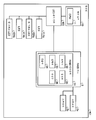
도 11은, 본 실시 형태에 따른 컴퓨터(401)의 전체 구성의 일례를 도시하는 도면이다. 컴퓨터(401)는 스토리지(2a, 2b)와, RAID 카드(3)와, 메인보드(10)와, LED(414a, 414b)와, 원 그래프 LED(424a, 424b)와, LED 제어 기반(405)을 구비한다. 스토리지(2a, 2b)와, RAID 카드(3)와, 메인보드(10)는, 실시 형태 1과 마찬가지의 기능을 구비한다.11 is a diagram showing an example of the overall configuration of the
원 그래프 LED(424a, 424b)(이하, 특별히 구별하지 않을 경우에는 원 그래프 LED(424)라고 함)는 복수의 LED가 원형으로 배열됨으로써, 원 그래프형 형상으로 된 발광부이다. 원 그래프 LED(424)는, 스토리지(2)마다 설치된다. 또한, 원 그래프 LED(424)는, 원형 바 그래프 LED라고도 한다.The
LED(414a, 414b)(이하, 특별히 구별하지 않을 경우에는 LED(414)라고 함)는 각각 단체의 LED이며, 일례로서, 원 그래프 LED(424a, 424b)의 중심에 각각 위치한다. 원 그래프 LED(424) 및 LED(414)는, 각 스토리지(2)이 격납된 드라이브 베이(21)의 근방에 설치된다.The
LED 제어 기반(405)은 스토리지(2)별 리빌드 처리의 진척 정도에 따라서, 원 그래프 LED(424)에 포함되는 복수의 LED 중, 점멸되는 LED의 수를 변화시킨다. 또한, LED 제어 기반(405)은 어느 스토리지(2)의 스테이터스가 이상일 경우에는, 스테이터스가 이상인 스토리지(2)에 대응지어진 LED(414)를 점등시킨다.The
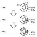
도 12는, 본 실시 형태에 따른 원 그래프 LED(424a)의 점멸의 변화의 일례를 도시하는 도면이다. 도 12의 원 그래프 LED(424a)의 사선 부분에 포함되는 LED는 점멸되고, 그 이외의 부분의 LED는 소등되어 있다. 스토리지(2a)가 리빌드 처리 중일 경우, LED 제어 기반(405)은 스토리지(2a)의 리빌드 처리의 진척 정도가 높아짐에 따라, 원 그래프 LED(424a)에 포함되는 복수의 LED를, 중앙 상방으로부터 시계 방향의 순으로 점멸시킨다. 이 때문에, 스토리지(2a)의 리빌드 처리의 진척 정도가 높아질수록, 원 그래프 LED(424a)의 점멸 범위가 넓어진다.12 is a diagram showing an example of a change in blinking of the circle-
도 12의 예에서는 스토리지(2a)의 스테이터스는 정상적이기 때문에, LED(414a)는 소등되어 있다. 스토리지(2a)의 스테이터스가 이상인 경우에는, LED 제어 기반(405)은 LED(414a)를 점등시킨다. 도 12에서는 원 그래프 LED(424a) 및 LED(414a)를 예로 했지만, 원 그래프 LED(424b)의 발광의 양태도 마찬가지이다.In the example of Fig. 12, since the status of the
또한, 본 실시 형태에 따른 RAID 컨트롤러(31)가 실행하는 처리의 수순은, 도 4에서 설명한 실시 형태 1의 수순과 마찬가지이다.In addition, the procedure of processing executed by the RAID controller 31 according to the present embodiment is the same as that of the first embodiment described in FIG. 4.
이와 같이, 본 실시 형태의 컴퓨터(401)에 의하면, 원 그래프 LED(424)를 사용함으로써, 작은 설치 면적으로 각 스토리지(2)에 있어서의 리빌드 처리의 진척 정도를 상세하게 나타낼 수 있다.As described above, according to the
(실시 형태 5)(Embodiment 5)
실시 형태 1 내지 4에서는, 컴퓨터(1, 201, 301, 401)에 의한 처리에서 리빌드 처리의 진척 정도의 표시가 완결되었지만, 표시의 방법은 이에 한정되는 것은 아니다. 실시 형태 5에서는, 리빌드 처리의 진척 정도를 가시광 통신에 의해 다른 디바이스에 전송함으로써, 다른 디바이스에서 진척 정도를 표시하는 것을 가능하게 한다.In Embodiments 1 to 4, in the processing by the
도 13은, 본 실시 형태에 따른 컴퓨터(501)의 전체 구성의 일례를 도시하는 도면이다. 컴퓨터(501)는 스토리지(2a, 2b)와, RAID 카드(3)와, 메인보드(10)와, LED(4a, 4b)와, LED 제어 기반(5)과, 변조 회로(6)를 구비한다. 스토리지(2a, 2b)와, RAID 카드(3)와, 메인보드(10)와, LED(4a, 4b)와, LED 제어 기반(5)은, 실시 형태 1과 마찬가지의 기능을 구비한다.13 is a diagram showing an example of the overall configuration of the computer 501 according to the present embodiment. Computer 501 includes storage (2a, 2b), RAID card (3), main board (10), LEDs (4a, 4b), LED control base (5), and modulation circuit (6) do. The
변조 회로(6)는 LED 제어 기반(5)이 LED(4)를 점멸시킬 경우에, LED(4)의 점멸의 주기를, 가시광 통신의 프로토콜에 기초하여 스토리지(2)별 리빌드 처리의 진척 정도를 나타내는 주기로 변조한다. 변조 회로(6)는 LED 제어 기반(5) 또는 메인보드(10) 상에 마련되어도 된다. 또한, 변조 회로(6)의 기능은 소프트웨어 프로그램으로 실현되어도 된다.When the LED control base 5 blinks the LED 4, the modulation circuit 6 determines the period of blinking of the LED 4 and the progress of the rebuild process for each storage 2 based on the protocol of visible light communication. It is modulated with a period indicating The modulation circuit 6 may be provided on the LED control base 5 or the
변조 회로(6)가 점멸 주기를 변조시킴으로써, LED(4)가 출력하는 광은 가시광 통신의 프로토콜에 기초하여 리빌드 처리의 진척 정도의 수치를 나타내는 신호로 된다. 가시광 통신의 신호는, 가시광 통신의 프로토콜에 기초하여 데이터를 판독하는 애플리케이션이 미리 인스톨된 스마트폰이나 태블릿 PC(Personal Computer) 등의 디바이스에 의해 판독 가능하다.By modulating the blinking period by the modulation circuit 6, the light output from the LED 4 becomes a signal representing a numerical value of the progress of the rebuild process based on the protocol of visible light communication. The signal of visible light communication can be read by a device such as a smartphone or a tablet PC (Personal Computer) in which an application for reading data is previously installed based on the protocol of visible light communication.
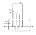
도 14는, 본 실시 형태에 따른 리빌드 처리의 진척 정도의 표시의 일례를 도시하는 도면이다. 도 14에 도시되는 스마트폰(7)에는, 가시광 통신을 판독하는 애플리케이션이 인스톨되어 있다. 스마트폰(7)은 당해 애플리케이션에 의해, 스마트폰(7)에 탑재된 카메라가 촬상한 LED(4)의 광으로부터, 스토리지(2)별 리빌드 처리의 진척 정도를 판독한다.14 is a diagram showing an example of display of the progression degree of the rebuild process according to the present embodiment. In the
또한, 본 실시 형태에서는, 스마트폰(7)은 디스플레이(71) 상에 배경으로서 촬상 화상을 표시하고, 표시된 촬상 화상 상에 리빌드 처리의 진척 정도를 중첩하여 표시한다. 도 14에 도시되는 예에서는, LED(4a)의 광이 나타내는 스토리지(2a)의 리빌드 처리의 진척 정도와, LED(4b)의 광이 나타내는 스토리지(2b)의 리빌드 처리의 진척 정도는 양쪽 모두 "11%"로 한다. 이 경우, 스마트폰(7)은 판독된 진척 정도의 값 "11%"을, 디스플레이(71)에 표시된 화상 상의 LED(4a, 4b)의 근방에 각각 표시한다. 도 14에 도시되는 표시 양태는 일례이며, 이에 한정되는 것은 아니다.In addition, in this embodiment, the
또한, 본 실시 형태에 따른 RAID 컨트롤러(31)이 실행하는 처리의 수순은, 도 4에서 설명한 실시 형태 1의 수순과 마찬가지이다.In addition, the procedure of the processing executed by the RAID controller 31 according to the present embodiment is the same as the procedure of the first embodiment described in FIG. 4.
이와 같이, 본 실시 형태의 컴퓨터(501)에서는, 가시광 통신의 프로토콜에 기초하여 리빌드 처리의 진척 정도를 나타내는 주기로 LED(4)를 점멸시키기 때문에, 스마트폰(7) 등의 디스플레이(71) 상에 리빌드 처리의 진척 정도를 퍼센트 등의 수치로 표시시킬 수 있다. 이 때문에, 본 실시 형태의 컴퓨터(501)에 의하면, 유저는 보다 상세한 진척 정도를 파악할 수 있다. 또한, 본 실시 형태의 컴퓨터(501)에 의하면, 가시광이 미치는 범위 내이면, 육안으로는 LED(4)의 점멸 주기 등의 판별이 곤란한 거리에서도, 리빌드 처리의 진척 정도를 유저가 용이하게 파악할 수 있다.As described above, in the computer 501 of the present embodiment, the LED 4 is flashed at a cycle indicating the progress of the rebuild process based on the protocol of visible light communication, so that it is displayed on the
또한, 일반적으로, 가시광 통신에 있어서의 LED(4)의 점멸 속도가 고속인 경우, 육안으로는 LED(4)는 계속적으로 점등되어 있는 것처럼 보이지만, 점멸 속도를 늦춤으로써 육안으로도 LED가 점멸되고 있는 것을 인식 가능한 구성을 채용해도 된다.In addition, in general, when the flashing speed of the LED 4 in visible light communication is high, it appears to the naked eye that the LED 4 is continuously lit, but by slowing the flashing speed, the LED flashes even with the naked eye. A configuration capable of recognizing the presence may be employed.
(실시 형태 6)(Embodiment 6)
실시 형태 6에서는, 실시 형태 1 내지 4과 마찬가지로 LED(4)의 발광에 의해 스토리지(2)별 스테이터스 또는 리빌드 처리의 진척 정도를 표시함에 더하여, LED(4)의 발광색을 변경함으로써 스토리지(2)별 액세스 빈도를 표시한다.In the sixth embodiment, in addition to displaying the status of each storage 2 or the progress of the rebuild process by light emission of the LEDs 4, as in the first to fourth embodiments, the storage 2 by changing the light emission color of the LEDs 4 Displays the frequency of each access.
본 실시 형태의 컴퓨터(1)는 실시 형태 1과 마찬가지로, 스토리지(2a, 2b)와, RAID 카드(3)와, 메인보드(10)와, LED(4a, 4b)와, LED 제어 기반(5)을 구비한다. 메인보드(10)와, 스토리지(2a, 2b)는, 실시 형태 1과 마찬가지의 기능을 구비한다.The computer 1 of this embodiment is similar to the first embodiment, the
본 실시 형태의 LED(4)는, 실시 형태 1의 기능에 더하여, 복수의 다른 색으로 발광 가능한 다색 타입의 LED이다. 구체적으로는, 본 실시 형태의 LED(4)는, 적색과 녹색으로 발광 가능한 2색 LED로 한다. 또한, LED(4)는, RGB 풀컬러 LED 등이어도 된다.The LED 4 of the present embodiment is a multicolor type LED capable of emitting light in a plurality of different colors in addition to the function of the first embodiment. Specifically, the LED 4 of this embodiment is a two-color LED capable of emitting light in red and green. Further, the LED 4 may be an RGB full color LED or the like.
본 실시 형태의 RAID 카드(3)는 실시 형태 1과 마찬가지로 RAID 컨트롤러(31)를 구비한다. RAID 컨트롤러(31)는 실시 형태 1과 마찬가지로, 취득부(32)와, 실행부(33)와, 산출부(34)와, 송신부(35)와, 수신부(36)를 구비한다. 취득부(32), 실행부(33), 수신부(36)는 실시 형태 1과 마찬가지의 기능을 구비한다.The
본 실시 형태의 산출부(34)는 실시 형태 1의 기능에 더하여, 스토리지(2)별 액세스 빈도를 산출한다. 액세스 빈도는, 메인보드(10)에 탑재된 CPU(11)로부터 스토리지(2a, 2b)에 대하여 소정의 시간 내에 실행되는 데이터의 판독 기입(액세스)의 빈도이다.The
보다 상세하게는, 산출부(34)는 소정의 시간마다, 실행된 데이터의 판독 기입의 횟수를 스토리지(2)마다 집계한다. 산출부(34)는 집계된 횟수가 소정의 횟수 이상인 경우에는, 당해 소정의 시간에 있어서의 액세스 빈도를 "고", 집계된 횟수가 소정의 횟수 미만인 경우에는, 액세스 빈도를 "저"로 산출한다.In more detail, the
본 실시 형태의 송신부(35)는 실시 형태 1의 기능에 더하여, 산출부(34)에 의해 산출된 스토리지(2)별 액세스 빈도를, LED 제어 기반(5)으로 송신한다.The
본 실시 형태의 LED 제어 기반(5)은 실시 형태 1의 기능에 더하여, 스토리지(2)별 액세스 빈도에 따라서 LED(4)를 다른 양태로 발광시킨다. 구체적으로는, LED 제어 기반(5)은 리빌드 처리의 실행 중에, 스토리지(2)별 액세스 빈도가 "고"인 경우에는, 당해 스토리지(2)에 대응지어진 LED(4)를 적색으로 점멸시킨다. 또한, LED 제어 기반(5)은 리빌드 처리의 실행 중에, 스토리지(2)별 액세스 빈도가 "저"인 경우에는, 당해 스토리지(2)에 대응지어진 LED(4)를 녹색으로 점멸시킨다.In addition to the functions of the first embodiment, the LED control base 5 of the present embodiment causes the LED 4 to emit light in different modes according to the access frequency for each storage 2. Specifically, when the access frequency for each storage 2 is "high" during execution of the rebuild process, the LED control base 5 causes the LED 4 corresponding to the storage 2 to blink red. Further, the LED control base 5 flashes the LED 4 corresponding to the storage 2 in green when the access frequency for each storage 2 is "low" during the execution of the rebuild process.
일반적으로, CPU(11)로부터 스토리지(2)에 대한 액세스 빈도가 높을 경우, 리빌드 처리가 종료될 때까지의 시간이 길어진다. 예를 들어, 리빌드 처리의 실행 중에 병행하여 다른 처리가 실행되는 경우, 당해 다른 처리에 의해 스토리지(2)의 액세스 빈도가 높아지면, 리빌드 처리가 종료될 때까지의 시간이 길어지는 경우가 있다.In general, when the frequency of access from the
또한, LED 제어 기반(5)은 어느 스토리지(2)의 스테이터스가 이상일 경우에는, 당해 스토리지(2)에 대응지어진 LED(4)를 적색으로 점등시킨다. 본 실시 형태에 있어서의 LED(4)의 발광색은 일례이며, 이에 한정되는 것은 아니다.In addition, the LED control base 5 turns on the LED 4 corresponding to the storage 2 in red when the status of any storage 2 is abnormal. The light emission color of the LED 4 in this embodiment is an example, and is not limited thereto.
도 15는, 본 실시 형태에 따른 리빌드 처리의 진척 정도의 산출 처리의 수순의 일례를 나타내는 흐름도이다. S1의 스토리지(2)의 스테이터스 정보와 리빌드 상태의 취득으로부터, S7의 리빌드 처리의 진척 정도의 송신까지의 처리는, 실시 형태 1과 마찬가지이다.15 is a flowchart showing an example of the procedure for calculating the progress of the rebuild process according to the present embodiment. The processing from the acquisition of the status information and the rebuild state of the storage 2 in S1 to the transmission of the progress of the rebuild process in S7 is the same as in the first embodiment.
송신부(35)가 실행 중인 리빌드 처리의 진척 정도를 LED 제어 기반(5)으로 송신한 후(S7), 산출부(34)는 스토리지(2)별 액세스 빈도("고" 또는 "저")를 산출한다(S61).After transmitting the progress of the rebuild process being executed by the
그리고, 송신부(35)는 산출부(34)에 의해 산출된 스토리지(2)별 액세스 빈도를, LED 제어 기반(5)으로 송신한다(S62). LED 제어 기반(5)은 송신된 스토리지(2)별 액세스 빈도가 "고"인 경우에는, 당해 스토리지(2)에 대응지어진 LED(4)를 적색으로 점멸시킨다. 또한, LED 제어 기반(5)은 송신된 스토리지(2)별 액세스 빈도가 "저"인 경우에는, 당해 스토리지(2)에 대응지어진 LED(4)를 녹색으로 점멸시킨다.Then, the
S62의 처리 후에 실행되는 S8의 리빌드 처리의 종료의 판단 처리로부터, S9의 리빌드 처리가 종료되는 것의 송신 처리까지는, 실시 형태 1과 마찬가지이다.It is the same as that of the first embodiment from the determination processing of the end of the rebuild processing of S8 to the transmission processing of the end of the rebuild processing of S9, which is executed after the processing of S62.
이와 같이, 본 실시 형태의 컴퓨터(1)는 리빌드 처리의 진척 정도에 따라서 LED(4)를 다른 양태로 발광시키고, 또한 스토리지(2)별 액세스 빈도에 따라서 LED(4)를 다른 양태로 발광시킨다. 이 때문에, 본 실시 형태의 컴퓨터(1)에 의하면, 유저는, 리빌드 처리가 실행되고 있는 스토리지(2)의 액세스 빈도와 리빌드 처리의 진척 정도로부터, 리빌드 처리의 종료까지에 필요한 시간을 보다 정확하게 추측할 수 있다.As described above, the computer 1 of the present embodiment emits the LED 4 in different modes according to the progress of the rebuild process, and also causes the LED 4 to emit light in different modes according to the access frequency for each storage 2. . For this reason, according to the computer 1 of the present embodiment, the user more accurately estimates the time required until the end of the rebuild process from the access frequency of the storage 2 in which the rebuild process is being executed and the progress of the rebuild process. can do.
또한, 본 실시 형태의 컴퓨터(1)에 의하면, 유저는, 예를 들어 리빌드 처리가 실행되고 있는 스토리지(2)의 액세스 빈도가 높은 것을 파악함으로써, 리빌드 처리를 일단 중지하고, 다른 처리의 실행 종료 후 등에 다시 리빌드 처리를 실행한다라는 판단을 할 수 있다.In addition, according to the computer 1 of the present embodiment, the user temporarily stops the rebuild process by grasping that the access frequency of the storage 2 in which the rebuild process is being executed is high, and the execution of other processes ends. It can be determined that the rebuild process is executed again later or the like.
또한, 본 실시 형태에서는 액세스 빈도를 "고"와 "저"의 2단계로 나타냈지만, 예를 들어 소정의 시간 내의 스토리지(2)별 판독 기입의 횟수를, 액세스 빈도의 값으로서 사용하는 구성을 채용해도 된다.In this embodiment, although the access frequency is shown in two stages of "high" and "low", for example, a configuration in which the number of read/write per storage 2 within a predetermined time is used as a value of the access frequency. You may employ it.
또한, 본 실시 형태에서는, LED 제어 기반(5)은 리빌드 처리의 실행 중에 액세스 빈도에 따라서 LED(4)를 다른 색으로 점멸시키는 구성을 채용했지만, 리빌드 처리의 실행 중 이외에도, 액세스 빈도에 따라서 LED(4)를 다른 색으로 점등시키는 구성을 채용해도 된다.In addition, in the present embodiment, the LED control base 5 adopts a configuration in which the LED 4 flashes in different colors depending on the access frequency during the execution of the rebuild process. However, in addition to the execution of the rebuild process, the LED A configuration in which (4) is lit in a different color may be employed.
또한, 본 실시 형태에서는, 실시 형태 1의 구성에 대하여 액세스 빈도에 따라서 LED(4)를 다른 색으로 점멸시키는 구성을 조합했지만, 실시 형태 2 내지 5의 구성에 대하여 당해 구성을 조합해도 된다.In addition, in the present embodiment, the configuration of the first embodiment is combined with a configuration in which the LED 4 is flashed in different colors depending on the access frequency, but the configuration may be combined with the configuration of the second to the fifth embodiments.
이상 설명한 바와 같이, 실시 형태 1 내지 6에 따르면, 리빌드 처리의 진척의 정도를 유저가 용이하게 파악할 수 있는 RAID 장치를 제공한다.As described above, according to the first to sixth embodiments, a RAID device in which the user can easily grasp the degree of progress of the rebuild process is provided.
또한, 본 실시 형태의 컴퓨터(1)로 실행되는 리빌드 처리의 진척 정도의 산출 프로그램은, ROM 등에 미리 내장되어 제공된다. 또한, 본 실시 형태의 컴퓨터(1)로 실행되는 리빌드 처리의 진척 정도의 산출 프로그램은, 인스톨 가능한 형식 또는 실행 가능한 형식의 파일로 CD-ROM, 플렉시블 디스크(FD), CD-R, DVD(Digital Versatile Disk) 등의 컴퓨터로 판독 가능한 기록 매체에 기록하여 제공하도록 구성해도 된다.In addition, a program for calculating the progress of the rebuild process executed by the computer 1 of the present embodiment is provided in advance built into a ROM or the like. In addition, the program for calculating the progress of the rebuild process executed by the computer 1 of this embodiment is a CD-ROM, a flexible disk (FD), a CD-R, or a DVD (Digital Versatile Disk) or the like may be recorded on a computer-readable recording medium and provided.
또한, 본 실시 형태의 컴퓨터(1)로 실행되는 리빌드 처리의 진척 정도의 산출 프로그램을, 인터넷 등의 네트워크에 접속된 컴퓨터 상에 격납하고, 네트워크 경유로 다운로드시킴으로써 제공하도록 구성해도 된다. 또한, 본 실시 형태의 컴퓨터(1)로 실행되는 리빌드 처리의 진척 정도의 산출 프로그램을 인터넷 등의 네트워크 경유로 제공 또는 배포하도록 구성해도 된다.Further, a program for calculating the progress of the rebuild process executed by the computer 1 of the present embodiment may be provided by storing it on a computer connected to a network such as the Internet and downloading it via the network. Further, a program for calculating the progress of the rebuild process executed by the computer 1 of the present embodiment may be provided or distributed via a network such as the Internet.
본 실시 형태의 컴퓨터(1)로 실행되는 리빌드 처리의 진척 정도의 산출 프로그램은, 상술한 각 부(취득부, 실행부, 산출부, 송신부, 수신부)를 포함하는 모듈 구성으로 되어 있고, 실제의 하드웨어로서는 CPU(프로세서)가 상기 ROM으로부터 리빌드 처리의 진척 정도의 산출 프로그램을 판독하여 실행함으로써 상기 각 부가 주기억 장치 상에 로드되어, 취득부, 실행부, 산출부, 송신부, 수신부가 주기억 장치 상에 생성되도록 되어 있다.The program for calculating the progress of the rebuild process executed by the computer 1 of the present embodiment has a module configuration including each of the above-described units (acquisition unit, execution unit, calculation unit, transmission unit, and reception unit). As the hardware, the CPU (processor) reads and executes a program for calculating the progress of the rebuild process from the ROM, and is loaded onto each of the additional main memory devices, and the acquisition unit, execution unit, calculation unit, transmission unit, and reception unit It is supposed to be created.
본 발명의 몇몇 실시 형태를 설명했지만, 이들 실시 형태는, 예로서 제시된 것이며, 발명의 범위를 한정하는 것은 의도하지 않는다. 이 신규의 실시 형태들은, 기타의 다양한 형태로 실시되는 것이 가능하고, 발명의 요지를 일탈하지 않는 범위에서, 다양한 생략, 치환, 변경을 행할 수 있다. 이들 실시 형태들이나 그 변형은, 발명의 범위나 요지에 포함됨과 함께, 청구범위에 기재된 발명과 그 균등의 범위에 포함된다.Although some embodiments of the present invention have been described, these embodiments have been presented as examples, and are not intended to limit the scope of the invention. These novel embodiments can be implemented in various other forms, and various omissions, substitutions, and changes can be made without departing from the gist of the invention. These embodiments and modifications thereof are included in the scope and summary of the invention, and are included in the invention described in the claims and their equivalents.
Claims (7)
발광부를 제어하여 상기 리빌드 처리의 진척 정도에 따라서 상기 발광부를 다른 양태로 발광시키는 제어부
를 구비하는 RAID 장치.An execution unit that executes a rebuild process for restoring data stored in one or more of the plurality of storage devices from data stored in another storage device;
A control unit for controlling the light emitting unit to emit light in a different mode according to the progress of the rebuild process
RAID device having a.
상기 제어부는, 상기 진척 정도에 따라서, 상기 발광부의 점멸 주기를 변화시키는,
RAID 장치.The method of claim 1,
The control unit changes the flashing period of the light emitting unit according to the progression degree,
RAID device.
상기 제어부는, 상기 진척 정도에 따라서, 상기 발광부의 단위 시간당 점멸 횟수를 변화시키는,
RAID 장치.The method of claim 1,
The control unit changes the number of flashes per unit time of the light emitting unit according to the progression degree,
RAID device.
상기 발광부는, 상기 기억 장치마다 복수 설치되고,
상기 제어부는, 상기 기억 장치별 상기 진척 정도에 따라서, 복수의 상기 발광부 중, 점멸되는 상기 발광부의 수를 변화시키는,
RAID 장치.The method of claim 1,
A plurality of the light emitting units are provided for each of the storage devices,
The control unit changes the number of flashing light emitting units among the plurality of light emitting units according to the progress of each memory device,
RAID device.
복수의 상기 발광부는, 상기 기억 장치마다 바 그래프형 또는 원 그래프형으로 배열되는,
RAID 장치.The method of claim 4,
The plurality of light emitting units are arranged in a bar graph type or a circle graph type for each of the storage devices,
RAID device.
상기 발광부의 점멸 주기를, 가시광 통신의 프로토콜에 기초하여 상기 진척 정도를 나타내는 주기로 변조시키는 변조부를 더 구비하는,
RAID 장치.The method of claim 1,
Further comprising a modulator for modulating the blinking period of the light emitting unit to a period representing the progression based on a protocol of visible light communication,
RAID device.
프로세서로부터 상기 기억 장치에 대한 소정의 시간 내의 액세스 횟수인 액세스 빈도를 산출하는 산출부를 더 구비하고,
상기 제어부는, 추가로, 상기 액세스 빈도에 따라서 상기 발광부를 다른 양태로 발광시키는,
RAID 장치.The method according to any one of claims 1 to 6,
Further comprising a calculation unit for calculating an access frequency, which is the number of times of access to the storage device within a predetermined time from the processor,
The control unit further emits light in the light emitting unit in a different mode according to the access frequency,
RAID device.
Applications Claiming Priority (3)
| Application Number | Priority Date | Filing Date | Title |
|---|---|---|---|
| JP2018010770A JP2019128841A (en) | 2018-01-25 | 2018-01-25 | RAID device |
| JPJP-P-2018-010770 | 2018-01-25 | ||
| PCT/JP2018/032457 WO2019146148A1 (en) | 2018-01-25 | 2018-08-31 | Raid device |
Publications (1)
| Publication Number | Publication Date |
|---|---|
| KR20200100814A true KR20200100814A (en) | 2020-08-26 |
Family
ID=67395320
Family Applications (1)
| Application Number | Title | Priority Date | Filing Date |
|---|---|---|---|
| KR1020207021624A KR20200100814A (en) | 2018-01-25 | 2018-08-31 | RAID device |
Country Status (6)
| Country | Link |
|---|---|
| JP (1) | JP2019128841A (en) |
| KR (1) | KR20200100814A (en) |
| CN (1) | CN111630489A (en) |
| SG (1) | SG11202006785UA (en) |
| TW (1) | TW201933098A (en) |
| WO (1) | WO2019146148A1 (en) |
Families Citing this family (2)
| Publication number | Priority date | Publication date | Assignee | Title |
|---|---|---|---|---|
| JP2021182268A (en) * | 2020-05-19 | 2021-11-25 | Necプラットフォームズ株式会社 | Controller, information processing device, information processing method, and program |
| JP7352300B2 (en) * | 2021-04-30 | 2023-09-28 | 株式会社 ニューテック | Storage device and rebuild method |
Citations (3)
| Publication number | Priority date | Publication date | Assignee | Title |
|---|---|---|---|---|
| JP2013200764A (en) | 2012-03-26 | 2013-10-03 | Fujitsu Ltd | Storage system, storage device and data restoration method |
| JP2014123258A (en) | 2012-12-21 | 2014-07-03 | Hitachi Ltd | Disk array system, data recovery method, and data recovery program |
| JP2014170370A (en) | 2013-03-04 | 2014-09-18 | Nec Corp | Storage control device, storage device and storage control method |
Family Cites Families (5)
| Publication number | Priority date | Publication date | Assignee | Title |
|---|---|---|---|---|
| US7028213B2 (en) * | 2001-09-28 | 2006-04-11 | Hewlett-Packard Development Company, L.P. | Error indication in a raid memory system |
| CN102520880B (en) * | 2011-12-01 | 2014-11-05 | 浪潮电子信息产业股份有限公司 | System raid management module design method |
| US9886335B2 (en) * | 2013-10-07 | 2018-02-06 | American Megatrends, Inc. | Techniques for validating functionality of backplane controller chips |
| WO2015073042A1 (en) * | 2013-11-18 | 2015-05-21 | Hewlett-Packard Development Company, L.P. | Indicating rebuild state of storage devices |
| WO2016170662A1 (en) * | 2015-04-23 | 2016-10-27 | 株式会社フィックスターズ | Storage device capable of performing high-speed data transmission, program therefor, and adaptor |
-
2018
- 2018-01-25 JP JP2018010770A patent/JP2019128841A/en active Pending
- 2018-08-31 CN CN201880087351.7A patent/CN111630489A/en not_active Withdrawn
- 2018-08-31 KR KR1020207021624A patent/KR20200100814A/en unknown
- 2018-08-31 WO PCT/JP2018/032457 patent/WO2019146148A1/en active Application Filing
- 2018-08-31 SG SG11202006785UA patent/SG11202006785UA/en unknown
- 2018-09-05 TW TW107131110A patent/TW201933098A/en unknown
Patent Citations (3)
| Publication number | Priority date | Publication date | Assignee | Title |
|---|---|---|---|---|
| JP2013200764A (en) | 2012-03-26 | 2013-10-03 | Fujitsu Ltd | Storage system, storage device and data restoration method |
| JP2014123258A (en) | 2012-12-21 | 2014-07-03 | Hitachi Ltd | Disk array system, data recovery method, and data recovery program |
| JP2014170370A (en) | 2013-03-04 | 2014-09-18 | Nec Corp | Storage control device, storage device and storage control method |
Also Published As
| Publication number | Publication date |
|---|---|
| SG11202006785UA (en) | 2020-08-28 |
| TW201933098A (en) | 2019-08-16 |
| WO2019146148A1 (en) | 2019-08-01 |
| CN111630489A (en) | 2020-09-04 |
| JP2019128841A (en) | 2019-08-01 |
Similar Documents
| Publication | Publication Date | Title |
|---|---|---|
| US9713215B2 (en) | Identification of storage device for trouble shooting | |
| TWI624758B (en) | System for controlling indicator lights and method for controlling light-emitting diode | |
| US20070260734A1 (en) | Display device for indicating connection statuses of a communication channel provided between two systems and method thereof | |
| US20120133520A1 (en) | Computer chassis system and hard disk status display method thereof | |
| CN106445793A (en) | Multi-control storage hard disk running status indicating system and method | |
| US9164861B2 (en) | Drive mapping using a plurality of connected enclosure management controllers | |
| KR20200100814A (en) | RAID device | |
| TW201506615A (en) | Indication system for hard disk | |
| WO2008120337A1 (en) | Host bus adapter managing program, computer readable recording medium recording the same, recording method and recording device | |
| CN109240894A (en) | A kind of method, system and the computer readable storage medium of hard disk lighting | |
| CN108845763A (en) | A kind of system and method for managing disk state concentratedly | |
| TWI659302B (en) | Hdd monitoring system | |
| CN102479140A (en) | Computer system and hard disk state display method | |
| US8005993B2 (en) | System and method of a storage expansion unit for a network attached storage device | |
| TWI467368B (en) | Drive carrier light source control | |
| CN107765993B (en) | Hard disk interface device | |
| CN103593275A (en) | Disk information displaying method and device | |
| TWI576694B (en) | Hard disk drive operating status detection system | |
| US20150370679A1 (en) | Server and device for analyzing a signal thereof | |
| TW202008164A (en) | Light-emitting control system and method | |
| US20140344481A1 (en) | Detecting system for hard disk drive | |
| TW202008165A (en) | Backup method and backup system | |
| CN108919090A (en) | Circuit board and booting adjustment method for the debugging that is switched on | |
| US9865143B2 (en) | Status displaying device and method thereof for solid-state drive | |
| KR102290093B1 (en) | Light-emitting storage device and light-emitting control method |