KR20200100174A - Beverage dispenser with container binding feature - Google Patents
Beverage dispenser with container binding feature Download PDFInfo
- Publication number
- KR20200100174A KR20200100174A KR1020207021660A KR20207021660A KR20200100174A KR 20200100174 A KR20200100174 A KR 20200100174A KR 1020207021660 A KR1020207021660 A KR 1020207021660A KR 20207021660 A KR20207021660 A KR 20207021660A KR 20200100174 A KR20200100174 A KR 20200100174A
- Authority
- KR
- South Korea
- Prior art keywords
- container
- clamp
- container neck
- needle
- neck
- Prior art date
Links
- 235000013361 beverage Nutrition 0.000 title claims description 259
- 238000003780 insertion Methods 0.000 claims abstract description 6
- 230000037431 insertion Effects 0.000 claims abstract description 6
- 230000013011 mating Effects 0.000 claims description 30
- 230000008878 coupling Effects 0.000 claims description 14
- 238000010168 coupling process Methods 0.000 claims description 14
- 238000005859 coupling reaction Methods 0.000 claims description 14
- 230000004913 activation Effects 0.000 claims description 2
- 238000000034 method Methods 0.000 claims 46
- 239000007789 gas Substances 0.000 description 200
- 210000003739 neck Anatomy 0.000 description 173
- 239000007799 cork Substances 0.000 description 19
- 230000008859 change Effects 0.000 description 11
- 238000009826 distribution Methods 0.000 description 11
- 238000000605 extraction Methods 0.000 description 11
- 230000004044 response Effects 0.000 description 11
- XKRFYHLGVUSROY-UHFFFAOYSA-N Argon Chemical compound [Ar] XKRFYHLGVUSROY-UHFFFAOYSA-N 0.000 description 8
- 239000012530 fluid Substances 0.000 description 8
- 230000006870 function Effects 0.000 description 8
- 230000007246 mechanism Effects 0.000 description 8
- 238000004891 communication Methods 0.000 description 7
- 239000007788 liquid Substances 0.000 description 7
- 230000006835 compression Effects 0.000 description 6
- 238000007906 compression Methods 0.000 description 6
- 230000008901 benefit Effects 0.000 description 5
- 238000003825 pressing Methods 0.000 description 5
- 230000001105 regulatory effect Effects 0.000 description 5
- 230000007704 transition Effects 0.000 description 5
- CURLTUGMZLYLDI-UHFFFAOYSA-N Carbon dioxide Chemical compound O=C=O CURLTUGMZLYLDI-UHFFFAOYSA-N 0.000 description 4
- 230000004308 accommodation Effects 0.000 description 4
- 230000009471 action Effects 0.000 description 4
- 229910052786 argon Inorganic materials 0.000 description 4
- 230000001276 controlling effect Effects 0.000 description 4
- 239000000284 extract Substances 0.000 description 4
- 238000005259 measurement Methods 0.000 description 4
- 238000001514 detection method Methods 0.000 description 3
- 239000011888 foil Substances 0.000 description 3
- 238000012544 monitoring process Methods 0.000 description 3
- 238000003860 storage Methods 0.000 description 3
- IJGRMHOSHXDMSA-UHFFFAOYSA-N Atomic nitrogen Chemical compound N#N IJGRMHOSHXDMSA-UHFFFAOYSA-N 0.000 description 2
- 239000001569 carbon dioxide Substances 0.000 description 2
- 229910002092 carbon dioxide Inorganic materials 0.000 description 2
- 230000005484 gravity Effects 0.000 description 2
- QSHDDOUJBYECFT-UHFFFAOYSA-N mercury Chemical compound [Hg] QSHDDOUJBYECFT-UHFFFAOYSA-N 0.000 description 2
- 229910052753 mercury Inorganic materials 0.000 description 2
- 239000000203 mixture Substances 0.000 description 2
- 238000011022 operating instruction Methods 0.000 description 2
- 230000000007 visual effect Effects 0.000 description 2
- 230000005355 Hall effect Effects 0.000 description 1
- 230000002159 abnormal effect Effects 0.000 description 1
- 230000015572 biosynthetic process Effects 0.000 description 1
- 238000004140 cleaning Methods 0.000 description 1
- 238000010586 diagram Methods 0.000 description 1
- 230000000694 effects Effects 0.000 description 1
- 239000000796 flavoring agent Substances 0.000 description 1
- 235000019634 flavors Nutrition 0.000 description 1
- 239000011521 glass Substances 0.000 description 1
- 230000036541 health Effects 0.000 description 1
- 239000001307 helium Substances 0.000 description 1
- 229910052734 helium Inorganic materials 0.000 description 1
- SWQJXJOGLNCZEY-UHFFFAOYSA-N helium atom Chemical compound [He] SWQJXJOGLNCZEY-UHFFFAOYSA-N 0.000 description 1
- 230000000977 initiatory effect Effects 0.000 description 1
- 239000000976 ink Substances 0.000 description 1
- 230000015654 memory Effects 0.000 description 1
- 229910052754 neon Inorganic materials 0.000 description 1
- GKAOGPIIYCISHV-UHFFFAOYSA-N neon atom Chemical compound [Ne] GKAOGPIIYCISHV-UHFFFAOYSA-N 0.000 description 1
- 229910052757 nitrogen Inorganic materials 0.000 description 1
- 230000003287 optical effect Effects 0.000 description 1
- 230000003647 oxidation Effects 0.000 description 1
- 238000007254 oxidation reaction Methods 0.000 description 1
- 238000002360 preparation method Methods 0.000 description 1
- 238000012545 processing Methods 0.000 description 1
- 238000011084 recovery Methods 0.000 description 1
- 230000009467 reduction Effects 0.000 description 1
- 238000007789 sealing Methods 0.000 description 1
Images


Classifications
-
- B—PERFORMING OPERATIONS; TRANSPORTING
- B67—OPENING, CLOSING OR CLEANING BOTTLES, JARS OR SIMILAR CONTAINERS; LIQUID HANDLING
- B67D—DISPENSING, DELIVERING OR TRANSFERRING LIQUIDS, NOT OTHERWISE PROVIDED FOR
- B67D1/00—Apparatus or devices for dispensing beverages on draught
- B67D1/04—Apparatus utilising compressed air or other gas acting directly or indirectly on beverages in storage containers
- B67D1/0412—Apparatus utilising compressed air or other gas acting directly or indirectly on beverages in storage containers the whole dispensing unit being fixed to the container
-
- B—PERFORMING OPERATIONS; TRANSPORTING
- B67—OPENING, CLOSING OR CLEANING BOTTLES, JARS OR SIMILAR CONTAINERS; LIQUID HANDLING
- B67B—APPLYING CLOSURE MEMBERS TO BOTTLES JARS, OR SIMILAR CONTAINERS; OPENING CLOSED CONTAINERS
- B67B7/00—Hand- or power-operated devices for opening closed containers
- B67B7/24—Hole-piercing devices
- B67B7/26—Hole-piercing devices combined with spouts
-
- B—PERFORMING OPERATIONS; TRANSPORTING
- B67—OPENING, CLOSING OR CLEANING BOTTLES, JARS OR SIMILAR CONTAINERS; LIQUID HANDLING
- B67D—DISPENSING, DELIVERING OR TRANSFERRING LIQUIDS, NOT OTHERWISE PROVIDED FOR
- B67D1/00—Apparatus or devices for dispensing beverages on draught
- B67D1/08—Details
- B67D1/0801—Details of beverage containers, e.g. casks, kegs
- B67D1/0802—Dip tubes
-
- B—PERFORMING OPERATIONS; TRANSPORTING
- B67—OPENING, CLOSING OR CLEANING BOTTLES, JARS OR SIMILAR CONTAINERS; LIQUID HANDLING
- B67D—DISPENSING, DELIVERING OR TRANSFERRING LIQUIDS, NOT OTHERWISE PROVIDED FOR
- B67D1/00—Apparatus or devices for dispensing beverages on draught
- B67D1/08—Details
- B67D1/0878—Safety, warning or controlling devices
- B67D1/0882—Devices for controlling the dispensing conditions
- B67D1/0885—Means for dispensing under specific atmospheric conditions, e.g. under inert gas
-
- B—PERFORMING OPERATIONS; TRANSPORTING
- B67—OPENING, CLOSING OR CLEANING BOTTLES, JARS OR SIMILAR CONTAINERS; LIQUID HANDLING
- B67D—DISPENSING, DELIVERING OR TRANSFERRING LIQUIDS, NOT OTHERWISE PROVIDED FOR
- B67D1/00—Apparatus or devices for dispensing beverages on draught
- B67D1/08—Details
- B67D1/0888—Means comprising electronic circuitry (e.g. control panels, switching or controlling means)
-
- B—PERFORMING OPERATIONS; TRANSPORTING
- B67—OPENING, CLOSING OR CLEANING BOTTLES, JARS OR SIMILAR CONTAINERS; LIQUID HANDLING
- B67D—DISPENSING, DELIVERING OR TRANSFERRING LIQUIDS, NOT OTHERWISE PROVIDED FOR
- B67D1/00—Apparatus or devices for dispensing beverages on draught
- B67D1/08—Details
- B67D1/0889—Supports
-
- F—MECHANICAL ENGINEERING; LIGHTING; HEATING; WEAPONS; BLASTING
- F16—ENGINEERING ELEMENTS AND UNITS; GENERAL MEASURES FOR PRODUCING AND MAINTAINING EFFECTIVE FUNCTIONING OF MACHINES OR INSTALLATIONS; THERMAL INSULATION IN GENERAL
- F16B—DEVICES FOR FASTENING OR SECURING CONSTRUCTIONAL ELEMENTS OR MACHINE PARTS TOGETHER, e.g. NAILS, BOLTS, CIRCLIPS, CLAMPS, CLIPS OR WEDGES; JOINTS OR JOINTING
- F16B2/00—Friction-grip releasable fastenings
- F16B2/02—Clamps, i.e. with gripping action effected by positive means other than the inherent resistance to deformation of the material of the fastening
- F16B2/06—Clamps, i.e. with gripping action effected by positive means other than the inherent resistance to deformation of the material of the fastening external, i.e. with contracting action
- F16B2/10—Clamps, i.e. with gripping action effected by positive means other than the inherent resistance to deformation of the material of the fastening external, i.e. with contracting action using pivoting jaws
-
- B—PERFORMING OPERATIONS; TRANSPORTING
- B67—OPENING, CLOSING OR CLEANING BOTTLES, JARS OR SIMILAR CONTAINERS; LIQUID HANDLING
- B67D—DISPENSING, DELIVERING OR TRANSFERRING LIQUIDS, NOT OTHERWISE PROVIDED FOR
- B67D1/00—Apparatus or devices for dispensing beverages on draught
- B67D1/04—Apparatus utilising compressed air or other gas acting directly or indirectly on beverages in storage containers
- B67D1/0412—Apparatus utilising compressed air or other gas acting directly or indirectly on beverages in storage containers the whole dispensing unit being fixed to the container
- B67D1/0418—Apparatus utilising compressed air or other gas acting directly or indirectly on beverages in storage containers the whole dispensing unit being fixed to the container comprising a CO2 cartridge for dispensing and carbonating the beverage
-
- B—PERFORMING OPERATIONS; TRANSPORTING
- B67—OPENING, CLOSING OR CLEANING BOTTLES, JARS OR SIMILAR CONTAINERS; LIQUID HANDLING
- B67D—DISPENSING, DELIVERING OR TRANSFERRING LIQUIDS, NOT OTHERWISE PROVIDED FOR
- B67D1/00—Apparatus or devices for dispensing beverages on draught
- B67D2001/0095—Constructional details
- B67D2001/0096—Means for pressurizing liquid
- B67D2001/0098—Means for pressurizing liquid using a gas
-
- B—PERFORMING OPERATIONS; TRANSPORTING
- B67—OPENING, CLOSING OR CLEANING BOTTLES, JARS OR SIMILAR CONTAINERS; LIQUID HANDLING
- B67D—DISPENSING, DELIVERING OR TRANSFERRING LIQUIDS, NOT OTHERWISE PROVIDED FOR
- B67D1/00—Apparatus or devices for dispensing beverages on draught
- B67D1/04—Apparatus utilising compressed air or other gas acting directly or indirectly on beverages in storage containers
- B67D2001/0475—Type of gas or gas mixture used, other than pure CO2
- B67D2001/0481—Single inert gas, e.g. N2
-
- B—PERFORMING OPERATIONS; TRANSPORTING
- B67—OPENING, CLOSING OR CLEANING BOTTLES, JARS OR SIMILAR CONTAINERS; LIQUID HANDLING
- B67D—DISPENSING, DELIVERING OR TRANSFERRING LIQUIDS, NOT OTHERWISE PROVIDED FOR
- B67D1/00—Apparatus or devices for dispensing beverages on draught
- B67D1/04—Apparatus utilising compressed air or other gas acting directly or indirectly on beverages in storage containers
- B67D2001/0475—Type of gas or gas mixture used, other than pure CO2
- B67D2001/0487—Mixture of gases, e.g. N2 + CO2
-
- B—PERFORMING OPERATIONS; TRANSPORTING
- B67—OPENING, CLOSING OR CLEANING BOTTLES, JARS OR SIMILAR CONTAINERS; LIQUID HANDLING
- B67D—DISPENSING, DELIVERING OR TRANSFERRING LIQUIDS, NOT OTHERWISE PROVIDED FOR
- B67D1/00—Apparatus or devices for dispensing beverages on draught
- B67D1/08—Details
- B67D1/0801—Details of beverage containers, e.g. casks, kegs
- B67D2001/0812—Bottles, cartridges or similar containers
-
- B—PERFORMING OPERATIONS; TRANSPORTING
- B67—OPENING, CLOSING OR CLEANING BOTTLES, JARS OR SIMILAR CONTAINERS; LIQUID HANDLING
- B67D—DISPENSING, DELIVERING OR TRANSFERRING LIQUIDS, NOT OTHERWISE PROVIDED FOR
- B67D1/00—Apparatus or devices for dispensing beverages on draught
- B67D1/08—Details
- B67D1/0801—Details of beverage containers, e.g. casks, kegs
- B67D2001/0822—Pressurised rigid containers, e.g. kegs, figals
- B67D2001/0825—Pressurised rigid containers, e.g. kegs, figals details of dip tube
Abstract
분배 장치의 클램프(1)는, 클램프가 컨테이너 목부에 대해서 아래쪽으로 밀리거나 위쪽으로 당겨질 때, 클램프를 컨테이너 목부에 대해서 결합 및/또는 결합 해제하도록 배열되는 컨테이너 결합 표면(43)을 포함할 수 있다. 컨테이너 결합 표면(43)은, 위쪽 및 내측으로 경사진 하부 부분(43b), 및 컨테이너 목부에 대해서 위쪽 및 외측으로 경사지고 클램프가 컨테이너 목부에 대해서 수직으로 이동될 때 클램프를 반경방향 외측으로 그리고 컨테이너 목부로부터 멀리 이동시키는 상부 부분(43a)을 갖는, 표면을 포함할 수 있다. 걸쇠(9)가 분배 장치의 본체 부분(3)을 상부 위치에서 유지하여, 컨테이너가 예를 들어 클램프에 의해서 장치의 기부 부분(2)과 적절하게 결합될 때까지, 바늘(200) 삽입을 방지한다. 센서(81, 82)가 컨테이너와 장치의 결합 및/또는 컨테이너 내로의 바늘(200)의 삽입을 검출할 수 있다.The clamp 1 of the dispensing device may comprise a container engaging surface 43 that is arranged to engage and/or disengage the clamp against the container neck when the clamp is pushed downward or pulled upward against the container neck. . The container engaging surface 43, the lower portion 43b inclined upward and inward, and the clamp radially outward and container when inclined upward and outward with respect to the container neck and the clamp is moved vertically with respect to the container neck. It may comprise a surface, with an upper portion 43a moving away from the neck. The clasp 9 holds the body part 3 of the dispensing device in an upper position, preventing needle 200 insertion until the container is properly engaged with the base part 2 of the device, for example by means of a clamp. do. Sensors 81 and 82 may detect the engagement of the container and the device and/or insertion of the needle 200 into the container.
Description
관련 출원에 대한 상호 참조Cross-reference to related applications
본원은, 전체가 본원에서 참조로 포함되는, 2017년 12월 29일자로 출원된 "컨테이너 결합 특징부를 갖는 음료 분배기"라는 명칭의 미국 가특허출원 제62/611,952호의 35 U.S.C. § 119(e) 하의 이익을 주장한다.This application is the 35 U.S.C. of U.S. Provisional Patent Application No. 62/611,952 filed Dec. 29, 2017, filed Dec. 29, 2017, entitled “Beverage Dispenser with Container Coupling Features”, which is incorporated herein by reference in its entirety. Claims an interest under § 119(e).
본 발명은 일반적으로 컨테이너 내로부터 유체를 분배하거나 달리 추출하는 것, 예를 들어 와인 병으로부터 와인을 분배하는 것에 관한 것이다. 컨테이너에 클램핑되도록 배열된 장치를 포함하는 음료 분배기가 미국 특허 제9,010,588호 및 제7,712,637호에서 설명되어 있다.The invention relates generally to dispensing or otherwise extracting fluid from within a container, for example dispensing wine from a wine bottle. Beverage dispensers comprising a device arranged to be clamped to a container are described in US patents 9,010,588 and 7,712,637.
본 발명의 양태에 따른 하나 이상의 실시예는 사용자가, 코르크, 플러그, 탄성중합체 격막 또는 다른 폐쇄부에 의해서 밀봉된 병 내로부터 와인과 같은 음료를, 폐쇄부를 제거하지 않고, 회수하거나 달리 추출할 수 있게 한다. 일부 경우에, 병에 대한 밀봉을 유지하기 위해서 각각의 음료 추출 중에 그리고 추출 후에 폐쇄부가 제 위치에서 유지될 수 있으면서, 그러한 병으로부터 액체를 제거하는 것이 한 차례 이상 실시될 수 있다. 따라서, 음료 품질에 영향을 미치지 않거나 거의 미치지 않으면서, 음료가 병으로부터 다수의 횟수로 분배될 수 있고 각각의 추출 사이에서 긴 기간 동안 저장될 수 있다. 일부 실시예에서, 음료와 반응하는 공기와 같은 가스가, 병으로부터의 음료의 추출 중에 또는 그 이후에, 병 내로 도입되지 않거나 거의 도입되지 않을 수 있다. 따라서, 일부 실시예에서, 사용자는, 코르크를 제거하거나 손상시키지 않으면서, 그리고 공기 또는 다른 잠재적으로 유해한 가스 또는 액체가 병 내로 진입하는 것을 허용하지 않으면서, 와인을 와인 병으로부터 회수할 수 있다.One or more embodiments in accordance with aspects of the present invention allow the user to retrieve or otherwise extract beverages, such as wine, from within a bottle sealed by a cork, plug, elastomeric diaphragm or other closure, without removing the closure. To be. In some cases, removal of liquid from such bottles may be performed more than once during and after each beverage extraction to maintain a seal on the bottle while the closure may be held in place. Thus, the beverage can be dispensed multiple times from the bottle and stored for a long period between each extraction, with little or no effect on the beverage quality. In some embodiments, a gas, such as air that reacts with the beverage, may not be introduced into the bottle or may be little introduced into the bottle during or after extraction of the beverage from the bottle. Thus, in some embodiments, a user may recover wine from a wine bottle without removing or damaging the cork, and without allowing air or other potentially harmful gas or liquid to enter the bottle.
본 발명의 일 양태에서, 음료 분배 장치는, 음료 컨테이너로부터 압력 하에서 음료의 유동을 수용하도록 그리고 장치의 분배 배출구에서 음료를 분배하도록 배열된 바늘을 갖는 본체를 포함한다. 예를 들어, 바늘은, 와인 병과 같은 컨테이너로부터 음료를 압력 하에서 수용하는 하나 이상의 내강(lumen) 또는 통로를 포함할 수 있다. 일부 실시예에서, 바늘은 모두, 가압 가스를 컨테이너 내로 도입하기 위해서 그리고 음료를 컨테이너로부터 수용하기 위해서, 코르크 또는 컨테이너의 다른 폐쇄부를 통과할 수 있다. 바늘에 의해서 분배 배출구에 전달되는 음료가 사용자의 컵 또는 잔 내로 분배될 수 있다.In one aspect of the present invention, a beverage dispensing device comprises a body having a needle arranged to receive a flow of beverage under pressure from a beverage container and to dispense beverage at the dispensing outlet of the device. For example, the needle may include one or more lumens or passages for receiving under pressure a beverage from a container such as a wine bottle. In some embodiments, the needles may both pass through a cork or other closure of the container to introduce pressurized gas into the container and to receive beverages from the container. The beverage delivered to the dispensing outlet by the needle may be dispensed into the user's cup or cup.
일부 실시예에서, 장치의 기부가 클램프를 포함할 수 있고, 그러한 클램프는 본체에 부착될 수 있고 본체를 컨테이너 목부(neck)에 대해서 고정하기 위해서 컨테이너 목부에 결합되도록 배열될 수 있다. 예를 들어, 클램프는, 컨테이너 목부에 결합되도록 그리고 본체를 상승시키는 것이 본체 및 결합된 컨테이너 모두를 상승시킬 수 있게 본체를 고정하도록 배열된 하나 이상의 클램프 아암을 포함할 수 있다. 이는, 사용자가 본체만을 조작함으로써 음료를 컨테이너로부터 따르게 할 수 있다. 다른 배열에서, 다른 지지부가 없이 장치가 컨테이너로부터 매달리거나 달리 고정되도록, 클램프가 본체를 컨테이너에 고정할 수 있다. 일부 실시예에서, 적어도 하나의 클램프 아암이 컨테이너 목부를 수용 공간 내로 수용하기 위해서 클램프의 하단부에서 진입 개구부를 갖는 수용 공간을 형성할 수 있다. 즉, 컨테이너 목부를 클램프의 하단부에 위치되는 진입 개구부로 배치하는 것 그리고 컨테이너 목부를 수용 공간 내로 상향 이동시키는 것(또는 다른 방식으로, 진입 개구부를 컨테이너 목부 위에 배치하는 것 그리고 클램프를 컨테이너 목부 상으로 하향 이동시키는 것)에 의해서, 컨테이너 목부가 수용 공간 내로 삽입될 수 있다. 예로서, 컨테이너는 테이블 상단 또는 다른 표면 상에 배치될 수 있고, 컨테이너 목부는, 컨테이너 목부를 진입 개구부 내로 삽입하는 것 그리고 클램프를 컨테이너 목부에 대해서 하향 이동시키는 것에 의해서 클램프의 수용 공간 내로 완전히 수용될 수 있다. 일부 실시예에서, 적어도 하나의 클램프 아암이 기부에 대해서 이동되도록 스프링 편향될 수 있고, 그에 따라 목부가 수용 공간 내에 완전히 수용될 때, 컨테이너 목부에 결합력을 가할 수 있다. 클램프를 컨테이너 상으로 하향 이동시킴으로써 컨테이너 목부를 수용 공간 내로 수용할 때, 적어도 하나의 클램프 아암이 스프링 편향에 대항하여 이동될 수 있고, 그에 따라 수용 공간을 확대할 수 있고 컨테이너 목부가 완전히 수용되게 할 수 있다.In some embodiments, the base of the device may include a clamp, such a clamp may be attached to the body and arranged to be coupled to the container neck to secure the body to the container neck. For example, the clamp may include one or more clamp arms arranged to engage the container neck and to secure the body such that raising the body may raise both the body and the associated container. This allows the user to pour the beverage from the container by operating only the main body. In other arrangements, clamps may secure the body to the container such that the device is suspended or otherwise secured from the container without other supports. In some embodiments, at least one clamp arm may form a receiving space having an entry opening at the lower end of the clamp to receive the container neck into the receiving space. That is, placing the container neck into the entry opening located at the lower end of the clamp and moving the container neck upward into the receiving space (or in another way, placing the entry opening over the container neck and placing the clamp onto the container neck). Moving downward), the container neck can be inserted into the receiving space. As an example, the container may be placed on a table top or other surface, and the container neck will be fully received into the receiving space of the clamp by inserting the container neck into the entry opening and moving the clamp downward relative to the container neck. I can. In some embodiments, the at least one clamp arm can be spring biased to move relative to the base, thereby exerting a coupling force on the container neck when the neck is fully contained within the receiving space. When receiving the container neck into the receiving space by moving the clamp down onto the container, at least one clamp arm can be moved against the spring deflection, thereby expanding the receiving space and allowing the container neck to be fully received. I can.
일부 실시예에서, 적어도 하나의 클램프 아암은 컨테이너 목부의 수용 및 그 결합을 돕기 위한 컨테이너 결합 표면을 포함한다. 예를 들어, 결합 표면이 클램프 아암의 내측부 표면 상에서 수직으로 연장될 수 있고 컨테이너 목부의 이동을 안내하는데 도움을 줄 수 있을 뿐만 아니라, 클램프 아암을 기부에 대해서 이동시켜 컨테이너 목부의 적절한 결합을 가능하게 할 수 있다. 일부 실시예에서, 결합 표면은, 수용 공간에 대해서 내측으로 그리고 위쪽으로 경사진 하부 부분을 가질 수 있다. 하부 부분은, 컨테이너 목부를 수용 공간 내에 수용하기 위해서 클램프가 컨테이너 목부 상으로 아래쪽으로 밀릴 수 있도록 그리고, 적어도 하나의 클램프 아암이 컨테이너 목부 상으로 결합력을 가하는 동안, 적어도 하나의 클램프 아암을 컨테이너 목부로부터 멀리, 예를 들어 클램프 아암 상의 스프링 편향에 대항하여 이동시킬 수 있도록, 배열될 수 있다. 일부 경우에, 컨테이너 목부를 수용 공간 내에 수용하기 위해서 클램프가 컨테이너 목부에 대해서 하향 이동될 때, 하부 부분이 반경방향 외향 힘을 적어도 하나의 클램프 아암에 가하여 적어도 하나의 클램프 아암을 컨테이너 목부의 립으로부터 멀리 이동시키도록, 컨테이너 결합 표면의 하부 부분이 컨테이너 목부의 립(lip)과 접촉 배열될 수 있다. 일부 경우에, 예를 들어, 클램프가 컨테이너 목부에 대해서 위쪽으로 당겨질 때 완전히 수용된 컨테이너 목부로부터 클램프를 결합 해제시키게 상부 부분이 배열되도록, 컨테이너 결합 표면은, 수용 공간에 대해서 외측으로 그리고 위쪽으로 경사지는 하부 부분 위에 배치된 상부 부분을 포함한다. 상부 부분은 반경방향 외향 힘을 적어도 하나의 클램프 아암에 인가하여, 클램프가 컨테이너 목부에 대해서 위쪽으로 이동될 때, 적어도 하나의 클램프 아암을 스프링 편향에 대항하여 그리고 컨테이너 목부로부터 멀리 이동시킬 수 있다. 따라서, 결합 표면은, 컨테이너 목부를 제 위치에서 고정하기 위해서 수용 공간 내에 있을 때, 컨테이너 목부와 접촉할 수 있을 뿐만 아니라 반경방향 내향 힘을 컨테이너 목부에 가할 수 있으나, 클램프 및 컨테이너를 수직 방향으로 서로에 대해서 이동시키는 것에 의해서 클램프가 컨테이너 목부와 결합될 수 있게 하거나 그로부터 결합 해제되게 할 수 있다.In some embodiments, at least one clamp arm includes a container engagement surface to assist in receiving and engaging the container neck. For example, the mating surface may extend vertically on the inner surface of the clamp arm and may help guide the movement of the container neck, as well as moving the clamp arm relative to the base to enable proper mating of the container neck. can do. In some embodiments, the mating surface may have a lower portion that slopes inwardly and upwardly with respect to the receiving space. The lower portion allows the clamp to be pushed downwards onto the container neck to accommodate the container neck within the receiving space, and while the at least one clamp arm applies a coupling force onto the container neck, the at least one clamp arm is removed from the container neck. It can be arranged so as to be able to move away, for example against spring deflection on the clamp arm. In some cases, when the clamp is moved downward relative to the container neck to accommodate the container neck within the receiving space, the lower portion applies a radially outward force to the at least one clamp arm to disengage the at least one clamp arm from the lip of the container neck. To move away, the lower portion of the container mating surface can be arranged in contact with the lip of the container neck. In some cases, for example, the container mating surface is inclined outwardly and upwardly with respect to the receiving space so that the upper part is arranged to disengage the clamp from the fully received container throat when the clamp is pulled upward against the container neck. And an upper portion disposed over the lower portion. The upper portion can apply a radially outward force to the at least one clamp arm to move the at least one clamp arm against the spring deflection and away from the container neck when the clamp is moved upward relative to the container neck. Thus, the mating surface, when in the receiving space to fix the container neck in place, not only can contact the container neck but also apply a radially inward force to the container neck, but the clamp and the container are held together in a vertical direction. By moving relative to the clamp can be made to engage or disengage from the container neck.
일부 실시예에서, 적어도 하나의 클램프 아암은, 서로를 향해서 이동하도록 스프링 편향되고 컨테이너 목부와 결합하도록 배열된, 2개의 클램프 아암들을 포함하고, 컨테이너 목부는 클램프 아암들 사이의 수용 공간 내에 배치된다. 2개의 클램프 아암은 모두, 아암들이 서로를 향해서 그리고 서로로부터 멀리 이동될 수 있도록 기부에 이동 가능하게 장착될 수 있고, 각각의 클램프 아암은 전술한 바와 같은 결합 표면을 포함할 수 있다. 예를 들어, 클램프 아암은 클램프 아암의 근위 측면(proximal side) 상에서 기부에 피벗 가능하게 장착될 수 있고, 컨테이너 결합 표면이 아암의 원위 측면 상에 위치될 수 있다. 클램프를 컨테이너 목부 상으로 아래쪽으로 밀 때, 결합 표면들은 컨테이너 목부를 수용하기 위해서 스프링 편향에 대항하여 클램프 아암들을 서로로부터 멀리 이동시킬 수 있다. 기부는, 컨테이너 목부의 상단부가 정지부와 접촉될 때 컨테이너 목부가 수용 공간 내에 완전히 수용되도록 클램프 아암들 사이에 배치된 컨테이너 목부의 상단부와 접촉되도록 수용 공간의 상부 단부에 배열되는, 바늘 안내부와 같은, 정지부를 포함할 수 있다.In some embodiments, at least one clamp arm includes two clamp arms, spring biased to move towards each other and arranged to engage the container neck, the container neck disposed within the receiving space between the clamp arms. Both clamp arms can be movably mounted on the base so that the arms can be moved towards and away from each other, and each clamp arm can include a mating surface as described above. For example, the clamp arm may be pivotally mounted to the base on the proximal side of the clamp arm, and the container engagement surface may be located on the distal side of the arm. When pushing the clamp down onto the container neck, the mating surfaces can move the clamp arms away from each other against the spring deflection to accommodate the container neck. The base is arranged at the upper end of the receiving space to contact the upper end of the container neck disposed between the clamp arms so that the container neck is fully received in the receiving space when the upper end of the container neck is in contact with the stop, and Like, it may include a stop.
본 발명의 다른 양태에서, 음료 분배 장치는 음료 컨테이너의 목부와 결합되는 기부, 및 상부 위치와 하부 위치 사이에서 기부에 대해서 이동 가능하게 장착되고 본체에 부착되고 본체로부터 연장되는 바늘을 가지는 본체를 포함할 수 있다. 바늘은, 가압 가스를 음료 컨테이너 내로 도입하기 위해서 그리고 음료를 컨테이너로부터 추출하기 위해서, 음료 컨테이너의 폐쇄부를 통해서 삽입되도록 배열될 수 있다. 컨테이너 목부가 기부에 의해서 결합될 때까지, 걸쇠가 본체를 상부 위치에서 해제 가능하게 로킹할 수 있고, 걸쇠는, 기부와 컨테이너 목부의 결합 시에, 바늘을 폐쇄부를 통해서 삽입하기 위해서 상부 위치로부터 하부 위치로 이동하도록 본체를 해제하게 배열될 수 있다. 예로서, 이러한 걸쇠 특징부는, 예를 들어 전술한 바와 같이 배열된, 클램프를 가지는 장치와 조합될 수 있고, 걸쇠는, 클램프가 컨테이너와 적절히 결합되고 장치가 바늘을 폐쇄부를 통해서 삽입할 준비가 될 때까지, 본체를 기부에 대해서 로킹할 수 있다. 일부 실시예에서, 사용자는, 단일 하향 이동으로, 컨테이너 목부를 클램프와 결합시킬 수 있고 이어서 즉각적으로 바늘을 컨테이너 폐쇄부를 통해서 삽입할 수 있다. 클램프와 관련하여 전술한 임의의 그리고 모든 특징부는, 단독적으로 또는 다양한 조합으로, 걸쇠 특징부와 조합될 수 있다.In another aspect of the present invention, a beverage dispensing device comprises a base coupled with the neck of the beverage container, and a body having a needle movably mounted with respect to the base and attached to the body and extending from the body between an upper position and a lower position. can do. The needle may be arranged to be inserted through the closure of the beverage container for introducing pressurized gas into the beverage container and for extracting beverage from the container. Until the container neck is engaged by the base, the clasp can releasably lock the main body in the upper position, and the clasp is from the upper position to the lower part to insert the needle through the closure when the base and the container neck are engaged. It can be arranged to release the body to move it into position. By way of example, such a clasp feature may be combined with a device having a clamp, for example arranged as described above, and the clasp may be such that the clamp is properly engaged with the container and the device is ready to insert the needle through the closure. Until then, the body can be locked against the base. In some embodiments, the user may engage the container neck with the clamp in a single downward movement and then immediately insert the needle through the container closure. Any and all of the features described above in connection with the clamp may be combined with the clasp features, alone or in various combinations.
일부 실시예에서, 기부는, 기부에 의해서 결합될 때, 컨테이너 목부의 상단부와 접촉하도록 배열되는 정지부를 포함하고, 걸쇠는, 컨테이너 목부의 상단부가 정지부와 접촉될 때, 이동을 위해 본체를 해제하도록 구성될 수 있다. 정지부는, 기부에 의해서 결합된 컨테이너 목부의 상단부와 접촉되도록 그리고 기부에 대한 본체의 하향 이동과 함께 폐쇄부를 통한 바늘의 이동을 안내하도록 배열된 바늘 안내부를 포함할 수 있다.In some embodiments, the base includes a stop arranged to contact an upper end of the container neck when engaged by the base, and the clasp releases the body for movement when the upper end of the container neck contacts the stop. Can be configured to The stop may comprise a needle guide arranged to contact the upper end of the container neck joined by the base and to guide movement of the needle through the closure with downward movement of the body relative to the base.
본 발명의 다른 양태에서, 음료 분배 장치는 음료 컨테이너의 목부와 결합되는 기부, 및 상부 위치와 하부 위치 사이에서 기부에 대해서 이동 가능하게 장착되고 본체에 부착되고 본체로부터 연장되는 바늘을 가지는 본체를 포함할 수 있다. 바늘은, 가압 가스를 음료 컨테이너 내로 도입하기 위해서 그리고 음료를 컨테이너로부터 추출하기 위해서, 음료 컨테이너의 폐쇄부를 통해서 삽입되도록 배열될 수 있다. 컨테이너 목부가 기부에 의해서 결합되었다는 것을 검출하도록 컨테이너 센서가 배열될 수 있고, 바늘이 음료 컨테이너의 폐쇄부를 통해서 삽입되었다는 것을 검출하도록 바늘 센서가 배열될 수 있다. 따라서, 일부 경우에, 분배 장치는 컨테이너 및/또는 바늘 센서로부터의 정보를 기초로 제어될 수 있고, 그에 따라, 장치가 음료 컨테이너와 적절히 결합되어야만 및/또는 바늘이 폐쇄부를 통해서 삽입되어야만 가스 전달 또는 음료 분배가 가능해진다.In another aspect of the present invention, a beverage dispensing device comprises a base coupled with the neck of the beverage container, and a body having a needle movably mounted with respect to the base and attached to the body and extending from the body between an upper position and a lower position. can do. The needle may be arranged to be inserted through the closure of the beverage container for introducing pressurized gas into the beverage container and for extracting beverage from the container. A container sensor can be arranged to detect that the container neck has been engaged by the base, and a needle sensor can be arranged to detect that a needle has been inserted through the closure of the beverage container. Thus, in some cases, the dispensing device may be controlled based on information from the container and/or the needle sensor, whereby the device must be properly engaged with the beverage container and/or the needle must be inserted through the closure to deliver gas or Beverage distribution becomes possible.
일부 실시예에서, 컨테이너 센서가 컨테이너와 기부의 결합을 검출한 경우에 그리고 바늘 센서가 폐쇄부를 통해서 삽입된 바늘을 검출한 경우에, 가스 유동이 가능하도록 제어기가 배열될 수 있다. 예로서, 기부는 컨테이너의 목부와 결합되도록 하기 위한 클램프를 포함할 수 있고, 컨테이너 센서는, 클램프가 컨테이너 목부와 결합된 것을 검출할 수 있다. 일부 경우에, 컨테이너 센서는, 클램프에 의해서 결합된 컨테이너 목부의 접촉에 의해서 작동되는 스위치를 포함한다. 기부는, 컨테이너 목부가 기부에 의해서 결합될 때, 컨테이너의 목부의 상단부와 접촉되도록 배열되는 정지부를 포함할 수 있고, 컨테이너 센서는, 컨테이너 목부의 상단부와 스위치의 접촉에 의해서 작동되는 스위치를 포함할 수 있다. 정지부는, 컨테이너의 폐쇄부를 통한 바늘의 이동을 안내하도록 배열된 바늘 안내부를 포함할 수 있다.In some embodiments, the controller may be arranged to enable gas flow when the container sensor detects the engagement of the container and the base and when the needle sensor detects a needle inserted through the closure. As an example, the base may include a clamp for engaging the neck of the container, and the container sensor may detect that the clamp is engaged with the neck of the container. In some cases, the container sensor includes a switch actuated by contact with the container neck engaged by a clamp. The base may include a stop arranged to contact the upper end of the neck of the container when the container neck is joined by the base, and the container sensor includes a switch actuated by contact of the upper end of the container neck with the switch. I can. The stop may comprise a needle guide arranged to guide movement of the needle through the closure of the container.
일부 실시예에서, 본체는 상부 위치와 하부 위치 사이에서 기부에 대해서 이동될 수 있고, 바늘 센서는, 본체가 기부에 대한 하부 위치에 있을 때 작동되는 스위치를 포함한다. 따라서, 바늘 센서는, 기부가 컨테이너 목부와 결합되었다는 것을 컨테이너 센서가 검출하였을 때, 바늘이 음료 컨테이너의 폐쇄부를 통해서 삽입되는 것을 검출하도록 배열될 수 있고, 바늘 센서 스위치가 작동되어, 본체가 하부 위치에 있다는 것을 나타낸다. 전술한 실시예에서와 같이, 본체는 컨테이너 목부와 결합되기 위한 클램프를 포함할 수 있고, 컨테이너 센서는 클램프에 의해서 결합된 컨테이너 목부에 의해서 작동될 수 있고, 바늘 센서는, 본체가 클램프에 대한 하부 위치에 있다는 것을 검출할 수 있고 그에 따라 바늘이 폐쇄부를 통해서 삽입되었다는 것을 나타낼 수 있다. 일부 경우에, 컨테이너 센서 스위치가 컨테이너 목부에 의해서 작동되고 바늘 센서 스위치가 하부 위치의 본체에 의해서 작동되는 경우에만, 가스 유동이 가능하도록 제어기가 배열될 수 있다.In some embodiments, the body can be moved relative to the base between an upper position and a lower position, and the needle sensor includes a switch that is activated when the body is in a lower position relative to the base. Thus, the needle sensor can be arranged to detect that the needle is inserted through the closure of the beverage container when the container sensor detects that the base has been engaged with the container neck, and the needle sensor switch is activated so that the body is in a lower position. Indicates that you are in. As in the above-described embodiment, the body may include a clamp for engaging with the container neck, the container sensor may be operated by the container neck coupled by the clamp, and the needle sensor, wherein the body is lower than the clamp It can detect that it is in position and thus indicate that the needle has been inserted through the closure. In some cases, the controller can be arranged to enable gas flow only if the container sensor switch is actuated by the container neck and the needle sensor switch is actuated by the body in the lower position.
일 실시예에서, 본체는 상부 위치와 하부 위치 사이에서 기부에 대해서 이동될 수 있고, 장치는, 컨테이너 센서가 컨테이너 목부에 의해서 작동될 때까지 본체를 상부 위치에서 해제 가능하게 로킹하는 걸쇠를 포함할 수 있다. 걸쇠는, 컨테이너 센서의 작동 시에 폐쇄부를 통해서 바늘을 삽입하기 위해서, 상부 위치로부터 하부 위치로의 이동을 위해 본체를 해제하도록 배열될 수 있다. 예를 들어, 걸쇠는, 컨테이너 센서가 컨테이너와의 결합을 검출한 때, 이동을 위해서 본체를 해제하도록 제어기에 의해서 전기적으로 작동될 수 있다.In one embodiment, the body may be moved relative to the base between the upper and lower positions, and the device includes a clasp that releasably locks the body in the upper position until the container sensor is actuated by the container neck. I can. The clasp may be arranged to release the body for movement from an upper position to a lower position, in order to insert the needle through the closure during actuation of the container sensor. For example, the clasp may be actuated electrically by the controller to release the body for movement when the container sensor detects engagement with the container.
일부 실시예에서, 장치는 가압 가스를 음료 컨테이너 내로 전달하도록 배열된 가압 가스 공급원을 포함할 수 있다. 음료 컨테이너 내의 가압 가스에 의해서 유발된 압력 하에서 음료의 유동을 수용하기 위해서, 장치가, 예를 들어 바늘에 의해서, 음료 컨테이너에 유체적으로 커플링될 수 있다. 음료 컨테이너 내로의 가압 가스의 유동을 제어하도록, 또는 음료 컨테이너로부터의 압력 하의 음료의 유동을 제어하도록, 밸브가 배열될 수 있다. 예를 들어, 가압 가스를 음료 컨테이너 내로 전달하기 위해서 음료 컨테이너의 폐쇄부를 통해서 삽입되도록 배열된 바늘을 장치가 포함하는 경우에, 밸브를 이용하여 바늘 내로의 가압 가스의 유동을 제어할 수 있고, 및/또는 도관을 통한 음료 컨테이너로부터의 압력 하의 음료의 유동을 제어할 수 있다.In some embodiments, the device may include a pressurized gas source arranged to deliver pressurized gas into the beverage container. In order to accommodate the flow of the beverage under pressure caused by the pressurized gas in the beverage container, the device can be fluidly coupled to the beverage container, for example by means of a needle. The valve can be arranged to control the flow of pressurized gas into the beverage container, or to control the flow of beverage under pressure from the beverage container. For example, if the device includes a needle arranged to be inserted through the closure of the beverage container to deliver the pressurized gas into the beverage container, a valve may be used to control the flow of the pressurized gas into the needle, and /Or it is possible to control the flow of the beverage under pressure from the beverage container through the conduit.
일 실시예에서, 분배 시스템은, 컨테이너가 유출(pour) 배향 또는 비-유출 배향에 있는지의 여부를 검출하기 위한 컨테이너 배향 센서를 포함할 수 있고, 제어기는, 컨테이너가 유출 배향에 있을 때 적어도 하나의 밸브를 제어하여 가스 또는 음료 유동을 허용하도록 그리고 컨테이너가 비-유출 배향에 있을 때 적어도 하나의 밸브를 제어하여 가스 또는 음료 유동을 방지하도록 배열될 수 있다. 예를 들어, 컨테이너 배향 센서는, 컨테이너의 하단부가 컨테이너의 개구부 위에 있을 때, 및/또는 컨테이너의 길이방향 축이 적어도 90도만큼 수평 축을 중심으로 회전될 때, 유출 조건을 검출할 수 있다. 따라서, 예를 들어, 사용자는, 음료를 병으로부터 유출시키기 위해서 통상적으로 사용되는 것과 유사한 방식으로 와인 병 또는 다른 컨테이너를 기울이거나 달리 조작할 수 있고, 시스템은 컨테이너 위치를 기초로 분배를 자동적으로 시작하거나 달리 제어할 수 있을 뿐만 아니라, 병이 직립 또는 거의 직립인 위치로 다시 기울여질 때, 분배를 정지시킬 수 있다.In one embodiment, the dispensing system may include a container orientation sensor to detect whether the container is in a pour orientation or a non-spill orientation, wherein the controller includes at least one It may be arranged to control the valve of the to allow gas or beverage flow and to control at least one valve to prevent gas or beverage flow when the container is in a non-spill orientation. For example, the container orientation sensor may detect the outflow condition when the lower end of the container is over the opening of the container and/or when the longitudinal axis of the container is rotated about the horizontal axis by at least 90 degrees. Thus, for example, a user can tilt or otherwise manipulate a wine bottle or other container in a manner similar to that commonly used to drain a beverage from the bottle, and the system automatically initiates dispensing based on the container position. It can be controlled or otherwise controlled, as well as stopping dispensing when the bottle is tilted back to an upright or nearly upright position.
일부 경우에, 제어기는, 컨테이너가 유출 배향에 있을 때, 적어도 하나의 밸브를 개방하여 가압 가스가 컨테이너 내로 유동할 수 있도록, 그리고 컨테이너가 비-유출 배향에 있을 때, 적어도 하나의 밸브를 폐쇄하여 가압 가스가 컨테이너 내로 유동하는 것을 방지하도록, 배열될 수 있다. 그러한 배열은 컨테이너에 접근하기 위해서 2개의 도관이 사용될 때 유용할 수 있고, 이때 하나의 도관은 가스를 컨테이너 내로 전달하고 다른 도관은 음료를 컨테이너로부터 전달한다. 다른 실시예에서, 바늘과 같은 적어도 하나의 도관이 단일 도관을 포함하고, 제어기는, 가압 가스가 단일 도관을 통해서 컨테이너 내로 유동할 수 있게 하기 위해서 적어도 하나의 밸브를 개방하는 것과, 컨테이너 내로 가압 가스가 유동하는 것을 방지하기 위해서 적어도 하나의 밸브를 폐쇄하는 것 사이에서 교번적이 되도록, 그리고 컨테이너가 유출 배향에 있을 때 음료가 단일 도관을 통해서 컨테이너로부터 유동될 수 있게 허용하도록, 배열된다. 다른 배열에서, 제어기는, 컨테이너가 유출 배향에 있을 때, 음료가 적어도 하나의 도관으로부터 음료 배출구까지 유동될 수 있게 허용하기 위해서 적어도 하나의 밸브를 개방하도록, 그리고 컨테이너가 비-유출 배향에 있을 때, 음료가 적어도 하나의 도관으로부터 음료 배출구까지 유동되는 것을 방지하기 위해서 적어도 하나의 밸브를 폐쇄하도록, 배열될 수 있다.In some cases, the controller opens at least one valve when the container is in the outflow orientation to allow pressurized gas to flow into the container, and when the container is in the non-outflow orientation, closes the at least one valve. It can be arranged to prevent pressurized gas from flowing into the container. Such an arrangement may be useful when two conduits are used to access the container, with one conduit transferring gas into the container and the other conduit transferring beverage from the container. In another embodiment, at least one conduit, such as a needle, comprises a single conduit and the controller opens at least one valve to allow pressurized gas to flow into the container through the single conduit, and pressurized gas into the container. It is arranged so as to alternate between closing at least one valve to prevent the flow of, and to allow beverage to flow from the container through a single conduit when the container is in the outflow orientation. In another arrangement, the controller opens at least one valve to allow beverage to flow from the at least one conduit to the beverage outlet when the container is in the outflow orientation, and when the container is in the non-spill orientation. , It can be arranged to close at least one valve to prevent the beverage from flowing from the at least one conduit to the beverage outlet.
일부 실시예에서, 제어기는, 적어도 하나의 밸브를 제어하여 규정된 양의 음료를 컨테이너로부터 분배하도록 배열될 수 있다. 예를 들어, 병으로부터 통상적으로 유출시키기 위해서 병을 사용자가 기울이는 경우에, 시스템은 6 온스와 같은 규정된 양의 음료를 자동적으로 분배할 수 있고, 병이 유출 배향에서 유지되는 경우에도 분배를 정지시킬 수 있다. 다른 서빙을 분배하기 위해서, 사용자는 병을 비-유출 배향으로 위치시키고 이어서 다시 유출 배향으로 위치시킬 필요가 있을 수 있다. 일부 실시예에서, 제어기는 적어도 하나의 밸브를 최대화된 음료 분배 속력을 위한 제1 모드 및 최소화된 가압 가스 사용을 위한 제2 모드를 포함하는 2개의 모드로 제어하도록 배열될 수 있다. 이는, 음료가 분배되는 속도(rate)를 사용자가 제어할 수 있게 하거나 필요에 따라 분배 가스를 보존할 수 있게 한다.In some embodiments, the controller may be arranged to control at least one valve to dispense a defined amount of beverage from the container. For example, if the bottle is tilted by the user to normally drain from the bottle, the system can automatically dispense a prescribed amount of beverage, such as 6 ounces, and stop dispensing even if the bottle is held in the outflow orientation. I can make it. In order to dispense another serving, the user may need to place the bottle in a non-spill orientation and then again in a spill orientation. In some embodiments, the controller may be arranged to control at least one valve in two modes including a first mode for maximized beverage dispensing speed and a second mode for minimized pressurized gas use. This allows the user to control the rate at which the beverage is dispensed or to conserve dispensing gas as needed.
일부 실시예에서, 컨테이너-장착형 음료 분배 시스템은, 음료를 유지하는 컨테이너 내로 가스를 전달하기 위한 그리고 사용자의 컵 내로 분배하기 위해서 컨테이너로부터 음료를 수용하기 위한 적어도 하나의 도관, 및 적어도 하나의 도관을 통한 컨테이너 내로의 가스 유동 또는 컨테이너의 외부로의 음료 유동을 제어하기 위한 적어도 하나의 밸브를 포함한다. 예를 들어, 단일 또는 다수-내강 바늘, 가스 제어 밸브, 음료 제어 밸브 등과 같은, 전술한 적어도 하나의 도관 및 밸브를 위한 배열이 이용될 수 있다. 컨테이너 배향 센서는 유출 배향 중에 길이방향 축을 중심으로 하는 컨테이너의 회전을 검출할 수 있고, 제어기는, 유출 배향 중에 길이방향 축을 중심으로 하는 컨테이너의 회전에 응답하는 가스 또는 음료 유동을 방지하기 위해서 적어도 하나의 밸브를 제어하도록 배열될 수 있다. 따라서, 예를 들어, 사용자는 병이 유출 배향에서 유지되는 동안 길이방향 축을 중심으로 병을 회전시킬 수 있고, 시스템은 음료 분배를 정지시키고 및/또는 병 내로의 가스의 전달을 정지시킬 수 있다. 이러한 배열은 사용자가 분배를 보다 양호하게 정지시키는데 도움을 줄 수 있고 병으로부터의 적하(drip)를 방지할 수 있다. 그러한 제어 배열은, 전술한 바와 같은 컨테이너의 유출/비-유출 배향을 기초로 분배를 제어하는 특징과 함께 이용될 수 있거나, 그러한 특징과 독립적으로 이용될 수 있다.In some embodiments, a container-mounted beverage dispensing system comprises at least one conduit, and at least one conduit for receiving beverage from the container for delivery of gas into the container holding the beverage and for dispensing into the user's cup. At least one valve for controlling gas flow into the container through or beverage flow out of the container. Arrangements for at least one conduit and valve described above may be used, such as, for example, single or multi-lumen needles, gas control valves, beverage control valves, and the like. The container orientation sensor can detect the rotation of the container about the longitudinal axis during the outflow orientation, and the controller can at least one to prevent gas or beverage flow in response to the rotation of the container about the longitudinal axis during the outflow orientation. It can be arranged to control the valve of. Thus, for example, a user can rotate a bottle about a longitudinal axis while the bottle is held in an outflow orientation, and the system can stop beverage dispensing and/or stop delivery of gas into the bottle. Such an arrangement can help the user better stop dispensing and prevent drip from the bottle. Such a control arrangement may be used with, or may be used independently of, the dispensing feature based on the outflow/non-outflow orientation of the container as described above.
다른 실시예에서, 컨테이너-장착형 음료 분배 시스템은, 가압 가스가 컨테이너에 전달되는 기간에 걸쳐 또는 음료가 컨테이너로부터 분배되는 기간에 걸쳐 압력 센서에 의해서 측정된 압력의 변화를 기초로 컨테이너 내의 음료의 부피를 결정하도록 배열된 제어기를 포함할 수 있다. 예를 들어, 제어기는 가스가 컨테이너에 전달되는 동안 컨테이너 내의 압력이 증가되는 속도를 검출할 수 있고, 압력 증가 속도를 기초로, 컨테이너 내의 액체 음료의 양을 결정할 수 있다. 다른 실시예에서, 제어기는 음료 분배 중에 컨테이너 내에서 압력이 감소되는 속도를 검출할 수 있고, 이러한 정보를 기초로, 컨테이너 내의 음료의 양을 결정할 수 있다. 일부 실시예에서, 제어기는, 예를 들어 음료가 분배될 수 있도록 음료 분배 밸브가 개방되어 있는 시간의 양을 결정하는 것에 의해서, 분배된 음료의 양을 결정할 수 있다. 예를 들어 컨테이너 내의 가스 압력을 기초로, 음료 분배의 유량이 알려져 있는 경우에, 제어기는 분배된 음료의 양을 결정할 수 있고, 그러한 양을 컨테이너 내의 초기 음료의 양으로부터 차감할 수 있다.In another embodiment, a container-mounted beverage dispensing system provides the volume of beverage in the container based on a change in pressure measured by the pressure sensor over a period during which pressurized gas is delivered to the container or over a period during which beverage is dispensed from the container. And a controller arranged to determine For example, the controller may detect the rate at which the pressure in the container increases while gas is being delivered to the container, and based on the rate of pressure increase, it may determine the amount of liquid beverage in the container. In another embodiment, the controller may detect the rate at which pressure is reduced in the container during beverage dispensing, and based on this information, determine the amount of beverage in the container. In some embodiments, the controller may determine the amount of beverage dispensed, for example by determining the amount of time the beverage dispensing valve is open so that the beverage may be dispensed. If the flow rate of the beverage dispense is known, for example based on the gas pressure in the container, the controller may determine the amount of beverage dispensed and may subtract that amount from the initial amount of beverage in the container.
일부 실시예에서, 제어기는, 시스템이 장착된 컨테이너의 신원과 관련된 정보를 수신하도록 배열될 수 있고, 제어기는 컨테이너 내의 음료의 양을 저장할 수 있다. 이러한 정보는, 시스템이 음료 분배를 위해서 사용되고, 컨테이너로부터 결합 해제되고, 이어서 음료 분배를 위해서 추후에 재결합되는 경우에, 유용할 수 있다. 제어기는 컨테이너 내에 남아 있는 음료의 양을 기억할 수 있고, 그에 따라, 예를 들어 남은 음료의 양을 기초로 컨테이너 내로의 가스의 유동을 제어하는 것에 의해서, 분배를 제어할 수 있다. 일부 경우에, 제어기는, 컨테이너 내로 전달된 가스의 양을 기초로, 분배 중에 컨테이너 내에 남아 있는 음료의 양을 결정하도록 배열될 수 있다. 예를 들어, 제어기는, 가압 가스를 컨테이너에 전달하기 위해서 가스 제어 밸브가 개방되어 있는 시간을 기초로, 컨테이너에 전달된 가스의 양을 결정할 수 있다. 가스가 압력 조절되거나 가스 유량의 다른 특성을 알 수 있는 경우에, 제어기는, 유량 및 가스 밸브의 개방 시간을 기초로, 전달된 가스의 양을 결정할 수 있다.In some embodiments, the controller may be arranged to receive information related to the identity of the container in which the system is mounted, and the controller may store the amount of beverage in the container. This information may be useful if the system is being used for beverage dispensing, disengaged from the container, and then recombined at a later time for beverage dispensing. The controller may memorize the amount of beverage remaining in the container and thus control the distribution, for example, by controlling the flow of gas into the container based on the amount of beverage remaining. In some cases, the controller may be arranged to determine the amount of beverage remaining in the container during dispensing based on the amount of gas delivered into the container. For example, the controller may determine the amount of gas delivered to the container based on the time the gas control valve is open to deliver the pressurized gas to the container. In cases where the gas is pressure regulated or other characteristics of the gas flow rate are known, the controller can determine the amount of gas delivered based on the flow rate and the opening time of the gas valve.
일부 실시예에서, 컨테이너-장착형 음료 분배 시스템은, 음료를 유지하는 컨테이너 내로 가스를 전달하기 위한 그리고 사용자의 컵 내로 분배하기 위해서 컨테이너로부터 음료를 수용하기 위한 적어도 하나의 도관, 및 적어도 하나의 도관을 통한 컨테이너 내로의 가스 유동을 제어하기 위한 적어도 하나의 밸브를 포함한다. 전술한 적어도 하나의 도관 및 적어도 하나의 밸브를 위한 배열이 이용될 수 있다. 가스 실린더가 적어도 하나의 도관에 유체적으로 커플링될 수 있고, 제어기는, 가스를 적어도 하나의 컨테이너 내로 전달하기 위해서 적어도 하나의 밸브가 개방되어 있는 시간의 양을 기초로, 가스 실린더 내의 압력을 결정하도록 배열될 수 있다. 예를 들어, 압력 센서를 이용하여 컨테이너 내의 가스 압력을 나타내는 압력을 검출할 수 있고, 제어기는, 가스를 컨테이너 내로 전달하기 위해서 적어도 하나의 밸브가 개방된 시간의 양 및 컨테이너 내의 가스 압력을 기초로, 가스 실린더 내의 압력을 결정할 수 있다. 예를 들어, 낮은 가스 실린더 압력은 적은 가스 유량에 상응할 수 있고, 그에 따라, 더 높은 압력의 가스 실린더보다 더 긴 컨테이너 내의 가스 공간을 가압하기 위한 시간에 상응할 수 있다.In some embodiments, a container-mounted beverage dispensing system comprises at least one conduit, and at least one conduit for receiving beverage from the container for delivery of gas into the container holding the beverage and for dispensing into the user's cup. And at least one valve for controlling gas flow through and into the container. Arrangements for at least one conduit and at least one valve described above may be used. The gas cylinder can be fluidly coupled to the at least one conduit, and the controller determines the pressure in the gas cylinder based on the amount of time the at least one valve has been open to deliver the gas into the at least one container. Can be arranged to determine. For example, a pressure sensor can be used to detect a pressure indicative of the gas pressure in the container, and the controller may be based on the amount of time the at least one valve is open and the gas pressure in the container to deliver the gas into the container. , The pressure in the gas cylinder can be determined. For example, a lower gas cylinder pressure may correspond to a lower gas flow rate and thus a time to pressurize a gas space in a longer container than a higher pressure gas cylinder.
장치의 여러 가지 예시적인 실시예가 이하에서 더 도시되고 설명된다.Several exemplary embodiments of the apparatus are further shown and described below.
본 발명의 양태가 다양한 실시예 및 도면을 참조하여 설명된다.
도 1은 음료 병의 폐쇄부를 통해서 도관을 도입하기 위한 준비에서의 음료 분배 장치의 개략도를 도시한다.
도 2는 도관이 폐쇄부를 통과한 도 1의 실시예를 도시한다.
도 3은 가스를 병 내로 도입하는 동안의 도 1의 실시예를 도시한다.
도 4는 음료를 병으로부터 분배하는 동안의 도 1의 실시예를 도시한다.
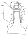
도 5는, 클램프 및 결합 표면을 포함하는 예시적인 실시예에서의 음료 분배 장치의 원근적 측면도를 도시한다.
도 6은 도 5의 분배 장치의 저면도를 도시한다.
도 7은 본체 걸쇠, 컨테이너 센서, 바늘 센서, 및 결합 표면을 가지는 클램프를 포함하는 분배 장치의 개략도를 도시한다.Aspects of the invention are described with reference to various embodiments and drawings.
1 shows a schematic view of a beverage dispensing device in preparation for introducing a conduit through a closure of a beverage bottle.
Fig. 2 shows the embodiment of Fig. 1 in which the conduit passes through the closure.
3 shows the embodiment of FIG. 1 during the introduction of gas into the bottle.
4 shows the embodiment of FIG. 1 during dispensing of a beverage from a bottle.
5 shows a perspective side view of a beverage dispensing device in an exemplary embodiment including a clamp and a mating surface.
6 shows a bottom view of the dispensing device of FIG. 5;
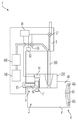
7 shows a schematic view of a dispensing device comprising a body clasp, a container sensor, a needle sensor, and a clamp having an engaging surface.
본 발명의 양태가 예시적인 실시예를 참조하여 이하에서 설명되나, 본 발명의 양태가 설명된 구체적인 실시예를 고려하여 좁게 해석되지 않아야 한다는 것을 이해하여야 한다. 따라서, 본 발명의 양태는 본원에서 설명된 실시예로 제한되지 않는다. 또한, 본 발명의 여러 양태가 단독적으로 사용될 수 있고 및/또는 임의의 적합한 서로의 조합으로 이용될 수 있고, 그에 따라 다양한 실시예가 특징부들의 임의의 특별한 조합 또는 조합들을 필요로 하는 것으로 해석되지 않아야 한다는 것을 이해하여야 한다. 그 대신, 설명된 실시예의 하나 이상의 특징이 다른 실시예의 임의의 다른 적합한 특징부와 조합될 수 있다. 예를 들어, 상이한 클램프, 걸쇠 및 센서 구성들이 이하에서 설명되고, 클램프, 걸쇠 및/또는 센서 특징부들의 다양한 조합이 이루어질 수 있다는 것을 이해하여야 한다.While aspects of the present invention are described below with reference to exemplary embodiments, it is to be understood that aspects of the invention should not be construed narrowly in view of the specific embodiments described. Accordingly, aspects of the present invention are not limited to the embodiments described herein. In addition, the various aspects of the invention may be used alone and/or in any suitable combination of each other, and thus the various embodiments should not be construed as requiring any particular combination or combinations of features. It should be understood that Instead, one or more features of the described embodiments may be combined with any other suitable features of other embodiments. For example, different clamp, clasp and sensor configurations are described below, and it should be understood that various combinations of clamp, clasp and/or sensor features may be made.
도 1 내지 도 4는, 본 발명의 하나 이상의 양태를 포함하는 음료 분배 장치(또는 추출기)(1)의 일 실시예의 개략도를 도시한다. 일반적으로, 장치(1)는 바늘을 음료 컨테이너(700) 내로 삽입하기 위해서, 바늘을 통해서 가스를 컨테이너(700) 내로 주입하기 위해서, 그리고 주입된 가스 또는 컨테이너 내의 다른 압력에 의해서 컨테이너(700)의 외부로 강제되는 음료를 분배하기 위해서 사용된다. 이러한 예시적인 장치(1)는, 압력(예를 들어, 실린더로부터 분배될 때 2600 psi 이하) 하에서 가스를 조절기(600)에 제공하는 (압축 가스 실린더와 같은) 가압 가스의 공급원(100)이 부착된 본체(3)를 포함한다. 이러한 배열에서, 실린더(100)는 나사산형 연결에 의해서 본체(3) 및 조절기(600)에 고정되나, 이하에서 및/또는, 가스 실린더를 실린더 수용부와 결합시키기 위한 메커니즘과 관련된 교시 내용과 관련하여 참조로 본원에 포함되는, US 특허 4,867,209; US 5,020,395; US 5,163,909 및 US 9,810,375에서 설명된 것과 같은, 다른 구성도 가능하다. 조절기(600)는 개략적으로 그리고 상세 부분이 없이 도시되어 있으나, 가스 압력을 미리-설정된 또는 가변적인 배출구 압력으로 조절할 수 있는, 다양한 상업적으로 입수가 가능한 또는 다른 단일 또는 다수-스테이지 압력 조절기 중 임의의 조절기일 수 있다. 조절기(600)의 주 기능은, 예를 들어, 컨테이너(700) 내에 형성된 압력이 희망 레벨을 넘지 않도록, (와인 병과 같은) 컨테이너(700)에 전달하기에 적합한 압력 및 유량으로 가스를 제공하는 것이다. 다른 실시예에서, 실린더(100)로부터 방출되는 가스의 압력을 조절할 필요가 없고, 그 대신, 미조절 가스 압력이 컨테이너(700)에 전달될 수 있다.1 to 4 show schematic diagrams of one embodiment of a beverage dispensing device (or extractor) 1 comprising one or more aspects of the present invention. In general, the
이러한 실시예에서, 본체(3)는 또한 가스의 유동 및/또는 컨테이너(700)로부터의 음료의 유동을 제어하기 위한 적어도 하나의 밸브를 포함한다. 이러한 실시예에서, 가스 제어 밸브(36)가 제공되어 가스 공급원(100)으로부터 컨테이너(700)의 내측부와 유체 연통되는 유동 경로까지의 가스의 유동을 제어하고, 음료 제어 밸브(37)는 컨테이너(700)로부터 분배 배출구(38)까지의 음료의 유동을 제어한다. (일부 실시예에서, 분배 배출구(38) 또는 배출구(38)의 일부, 예를 들어 관이, 예를 들어 세정을 위해서, 제거될 수 있거나 교체될 수 있다.) 그러나, 다른 배열도 가능하고, 예를 들어 단일 밸브가 (예를 들어, 3-방향 밸브를 이용하여) 가스 및 음료 모두의 유동을 제어할 수 있고, 단일 밸브를 이용하여 가스 유동만을 제어할 수 있고(예를 들어, 음료 유동 도관이 컨테이너 내측부로부터 분배 배출구로 항상 개방되어 있을 수 있고, 가스가 컨테이너 내로 도입될 때, 음료가 유동될 수 있고), 또는 단일 밸브를 이용하여 음료 유동만을 제어할 수 있다(예를 들어, 가스 공급원(100)으로부터 컨테이너(700)로의 가스 유동이, 컨테이너(700)와 결합된 장치(1)를 이용하여, 항상 개방될 수 있고, 음료 유동은 음료 제어 밸브만을 개방/폐쇄하는 것에 의해서 제어될 수 있다). 하나의 또는 둘 모두의 밸브(36, 37)가 제어기(34), 즉 제어 회로망에 의해서 제어될 수 있다. 예를 들어, 제어기(34)는, 예를 들어, 바늘이 코르크를 통해서 삽입된 것 또는 장치 클램프가 컨테이너 목부와 결합되는 것을 검출함으로써, 장치(1)가 컨테이너(700)와 결합되는 때를 검출될 수 있고, 이어서 그에 따라 밸브를 제어할 수 있다. 제어기(34)에 의해서 제어되지 않는 경우에, 밸브(36, 37)가 사용자에 의해서 수동으로 동작될 수 있고, 및/또는 사용자는 사용자 인터페이스(버튼, 터치 스크린 등)를 통해서 제어기(34)에 입력을 제공하여 밸브가 개방 및/또는 폐쇄되게 할 수 있다. 다른 선택 사항으로서, 하나의 밸브가 개방될 때 다른 밸브가 폐쇄되도록, 그리고 그 반대가 되도록, 또는 하나의 밸브가 개방될 때 다른 밸브도 개방되도록(예를 들어, 2개의 내강의 바늘을 이용할 때), 밸브들의 동작이, 기계적으로든 또는 전자 제어를 통하든 간에, 함께 연관될 수 있다.In this embodiment, the body 3 also comprises at least one valve for controlling the flow of gas and/or the flow of beverage from the
가스를 컨테이너(700) 내에 도입하고 음료를 추출하기 위해서, 적어도 하나의 도관이 컨테이너(700)의 내측부와 유체 연통된다. 이러한 실시예에서, 본체(3)에 부착된 바늘(200)이, 도 2에 도시된 바와 같이, 컨테이너(700)의 목부에 위치되는 개구부를 밀봉하는 코르크 또는 다른 폐쇄부(730)를 통해서 삽입된다. 이러한 예시적인 장치(1)에서, 바늘(200)은, 바늘 선단부 부근에서 바늘의 측벽을 따라 바늘 개구부(220)를 가지는 하나의 또는 2개의 내강 또는 도관을 포함한다. 바늘(200)이 상이한 방식들로 코르크 또는 다른 폐쇄부(730) 내로 삽입될 수 있지만, 이러한 실시예에서, 장치(1)는, 본체(3)의 각각의 레일(31)을 수용하고 그 이동을 안내하는 채널(21)의 쌍을 갖는 (이하에서 설명되는 바와 같은 클램프에 의해서 컨테이너(700)에 고정될 수 있는) 기부(2)를 포함한다. 따라서, 컨테이너 폐쇄부(730)에 대한 본체(3) 및 부착된 바늘(200)의 이동이 기부(2)에 의해서 안내될 수 있고, 예를 들어 본체(3)가 상부 위치와 하부 위치 사이에서 기부(2)에 대해서 활주되어 바늘(200)을 폐쇄부(730)의 내외로 이동시킬 수 있다. 또한, 바늘(200)의 이동은, 기부(2)에 부착되고 폐쇄부(730) 위에 배치되는 바늘 안내부(202)에 의해서 안내될 수 있다. 폐쇄부(730)를 통해서 바늘(200)을 삽입하기 위해서, 사용자는, 기부(2) 및 컨테이너(700)를 서로에 대해서 적어도 어느 정도 정지적으로 유지하면서, 본체(3)를 아래쪽으로 밀 수 있다. 바늘(200)은, 기부(2)에 대한 본체(3)의 안내된 이동에 의해서(예를 들어, 레일(31) 및 채널(21)에 의해서), 적어도 부분적으로, 이동이 안내되면서, 폐쇄부(730)를 통과할 것이다. 본체(3)의 채널 또는 다른 수용부와 결합되는 기부(2) 상에서 하나 이상의 레일을 제공하는 것, 본체 또는 기부 중 다른 하나 상의 상응 특징부(예를 들어, 탭)와 결합되고, 본체와 기부를 함께 연결하고 바늘을 폐쇄부 내로 삽입하기 위한 본체의 이동을 허용하는 링키지가 활주 이동 할 수 있게 하는, 세장형 슬롯, 채널 또는 홈을 본체 또는 기부 상에 제공하는 것과 같은, 기부(2)에 대한 본체(3)의 이동을 안내하기 위한 다른 배열이 가능하다.At least one conduit is in fluid communication with the inside of the
바늘(200)이 도 2에 도시된 바와 같이 삽입되면, 바늘 선단부에 위치되는 바늘 개구부(220)가 폐쇄부(730) 아래에 그리고 컨테이너(700)의 봉입된 공간(enclosed space) 내에 배치될 수 있다. 이는 컨테이너(700)의 내측부와 바늘(200)의 하나 이상의 도관 사이의 유체 연통을 가능하게 한다. 바늘(200)이 하나 이상의 내강 또는 도관을 포함하는 실시예에서, 밸브(36, 37)를 제어하여, 교번적으로, 가압 가스를 컨테이너(700) 내로 제공할 수 있고 음료가 컨테이너(700)로부터 유동하게 할 수 있다. 예를 들어, 가스가 먼저 단일 도관을 통해서 컨테이너(700) 내로 도입되어 컨테이너(700) 내에서 가압 조건을 형성할 수 있고, 이어서 가스 유동이 정지되고 가압된 음료가 단일 도관의 외부로 분배 배출구로 유동되게 할 수 있다. 바늘(200)이 2개의 내강 또는 도관을 포함하는 경우에 (또는 둘 이상의 바늘이 사용되는 경우에), 하나 이상의 도관이 컨테이너 내로의 가스 유동을 위해서 지정될 수 있고, 하나 이상의 다른 도관이 음료 유동을 위해서 지정될 수 있다. 따라서, 가스 제어 밸브(36)는 가스 도관(들) 내로의 가스 유동을 제어할 수 있고, 음료 제어 밸브(37)는 음료 도관(들)로부터의 음료 유동을 제어할 수 있다. 대안적으로, 밸브(36, 37) 중 하나 만이 음료 유동을 제어하기 위해서 제공될 필요가 있고, 예를 들어 가스 제어 밸브(36)가 개방/폐쇄될 수 있고 음료는, 컨테이너 내의 압력에 따라, 지정된, 항상 개방된 음료 도관을 통해서 컨테이너의 외부로 분배 배출구(38)까지 유동될 수 있다. 코르크 또는 다른 폐쇄부를 천공할 수 있는 바늘 또는 다른 구조물의 이용이 필수적이 아니라는 것을 이해하여야 한다. 그 대신, 임의의 적합한 호스, 파이프, 관 또는 다른 도관이 바늘로서 이용될 수 있고, 예를 들어 코르크가 제거될 수 있고, 예를 들어, 도관(들)이 통과하여 연장되는 플러그 또는 캡에 의해서, 도관이 컨테이너(700)에 유체적으로 커플링될 수 있다.When the
본 발명의 양태에 따라, 분배 장치는, 컨테이너 목부가 기부에 의해서 결합되었다는 것을 검출하도록 배열된 컨테이너 센서, 및 바늘이 음료 컨테이너의 폐쇄부를 통해서 삽입되었다는 것을 검출하도록 배열된 바늘 센서를 포함할 수 있다. 컨테이너 센서 및 바늘 센서는 다양한 상이한 방식들로 배열될 수 있다. 이러한 예시적인 실시예에서, 장치(1)는, 바늘 안내부(202)에 부착되고 컨테이너 목부의 상단부가 바늘 안내부(202)에 근접하거나 그와 접촉되는 때를 검출하는 컨테이너 센서(81)를 포함한다. 바늘 안내부(202)는, 도 1 및 도 2에서 볼 때 수직 방향으로(즉, 바늘(200)의 길이를 따르는 또는 바늘이 폐쇄부를 통해서 이동하는 경로를 따르는 방향으로) 기부(2)에 대한 컨테이너 목부의 이동을 제한하는 정지부로서 기능할 수 있고, 컨테이너 센서(81)는 컨테이너 목부의 상단부가 바늘 안내부(202)와 접촉되는 때를 검출할 수 있다. 물론, 바늘 안내부(202)가 요구되는 것은 아니고, 바늘 안내 기능을 제공하지 않으면서, 컨테이너 목부의 상단부를 기부(2)에 대해서 배치하는 것을 돕도록 정지부가 제공될 수 있다. 이러한 실시예에서, 컨테이너 센서(81)는 스위치를 포함하고, 그러한 스위치는, 컨테이너 목부가 정지부/바늘 안내부(202)에 대해서 적절히 배치되는 때, 예를 들어 컨테이너 목부의 상단부가 바늘 안내부(202)와 접촉될 때, 스위치가 폐쇄되거나, 개방되거나, 검출 가능 상태가 달리 변화되는 때에 작동될 수 있다. 그러나, (예를 들어, 컨테이너 목부의 근접도를 검출하는) 초음파 센서, (예를 들어, 컨테이너 목부와의 접촉에 의해서 이동된 자기 요소의 이동을 검출하는) 홀 효과 센서(Hall effect sensor), (예를 들어, 컨테이너 목부의 상단부에 의해서 차단되는 주변 광을 검출하는) 광학적 검출기를 포함하는, 컨테이너 센서(81)를 위한 다른 배열도 가능하다. 컨테이너 센서(81)는 또한 기부와의 결합을 검출하기 위한 임의의 적합한 방식으로 배치될 수 있다. 예를 들어, 기부(2)는 (이하에서 더 구체적으로 설명되는) 클램프를 포함할 수 있고, 컨테이너 센서(81)는, 클램프가 컨테이너 목부와 결합되는 때를 검출하기 위한 센서를 포함할 수 있고, 예를 들어 스트레인 게이지(strain gage)가, 컨테이너를 결합시키기 위해서 클램프에 힘이 가해지는 때를 검출할 수 있고, 스위치는, 클램프의 아암이 컨테이너 목부와의 결합으로 강제되는 때를 검출할 수 있고, 기타 등등이 이루어질 수 있다. 다른 배열에서, 컨테이너 센서(81)가 사용자에 의해서 작동될 수 있고, 예를 들어 장치(1)가 컨테이너와 적절히 결합되었을 때 사용자가 버튼을 누른다.According to an aspect of the invention, a dispensing device may include a container sensor arranged to detect that the container neck has been engaged by the base, and a needle sensor arranged to detect that a needle has been inserted through the closure of the beverage container. . The container sensor and needle sensor can be arranged in a variety of different ways. In this exemplary embodiment, the
제어기(34)는, 컨테이너 센서(81)의 검출 상태를 기초로, 가스 밸브(36) 및/또는 음료 밸브(37) 및/또는 장치(1)의 다른 부분을 제어할 수 있다. 예를 들어, 컨테이너(700)가 기부(2)와 적절히 결합되었다는 것을 컨테이너 센서(81)가 검출하지 않는 한, 제어기(34)는 가스 밸브(36)를 통한 가스의 전달을 허용하지 않을 수 있다. 이는, 가스가 적절할 때에만, 예를 들어 가압 가스를 수용하기 위해서 컨테이너가 장치(1)와 적절히 결합될 때에만 가스가 방출되도록 보장하는데 도움을 줄 수 있다. 대안적으로, 또는 부가적으로, 제어기(34)는, 컨테이너 센서(81)가 컨테이너(700)와의 결합을 검출하지 않는 한, 디스플레이를 디스에이블링(disable)시킬 수 있고, 또는 장치(1)가 컨테이너와 결합되어 있는지의 여부를 디스플레이 (예를 들어, 표시등, 터치 스크린과 연관된 다중-화소 디스플레이 등) 상에서 표시할 수 있다. 이는, 컨테이너가 장치(1)와 적절히 결합되도록 보장하는데 있어서 사용자에게 도움을 줄 수 있다. 제어기(34)는 또한 장치(1)의 하나 이상의 시스템을 "깨우기(wake)" 위해서 컨테이너 센서(81)의 검출 상태를 이용할 수 있고, 예를 들어 컨테이너가 결합되었다는 것을 컨테이너 센서(81)가 검출한 경우에, 디스플레이는, 장치(1)에 전원이 공급되고 동작을 위한 준비가 되어 있다는 것을 표시할 수 있거나, 폐쇄부(730) 내로 바늘(200)을 삽입하도록 하는 표시와 같은 지시, 및 기타를 제공할 수 있다. 제어기(34)는 컨테이너 센서(81) 표시에 응답하여 장치(1)에 대한 상태 체크를 실시할 수 있고, 예를 들어 음료를 분배하기에 적합한 가스 압력이 실린더(100) 내에 존재하는지, 배터리 전력(사용되는 경우)이 동작에 적합한지, 등을 결정하기 위해서 체크를 실시할 수 있고, 하나 이상의 메시지 또는 다른 디스플레이를 사용자에게 제공할 수 있다.The
앞서 주목한 바와 같이, 장치(1)는 또한, 바늘이 음료 컨테이너의 폐쇄부를 통해서 삽입되었는지의 여부를 검출하는 바늘 센서(82)를 포함할 수 있다. 바늘 센서(82)는 다양한 상이한 방식들로 구현될 수 있으나, 이러한 실시예에서, 본체(3)가, 예를 들어 도 2에 도시된 바와 같이, 기부(2)에 대한 하부 위치로 이동되었을 때를 검출하는 센서(예를 들어, 스위치)를 포함하고, 그러한 하부 위치로의 이동은 바늘(200)이 폐쇄부(730)를 통해서 삽입되었다는 것을 나타낼 수 있다. 예로서, 본체(3)가 하부 위치로 이동될 때, 스위치와 바늘 안내부(202)의 접촉에 의해서 스위치가 작동될 수 있다. 본체(3)가 기부(2)에 대해서 자유롭게 이동 가능한 경우에, 본체(3)가 기부(2)에 대한 하부 위치에 있다는 것을 나타내는 센서(82)가, 바늘(200)이 폐쇄부를 통해서 삽입되었다는 것을 반드시 나타내지 않을 수 있는데, 이는, 예를 들어, 본체(3) 및 바늘(200)이 하부 위치로 이동되기 전에, 기부(2)가 컨테이너(700)와 적절히 결합되지 않았기 때문일 수 있다. 일부 실시예에서, 제어기(34)는, 컨테이너 센서(81)로부터의 정보를 기초로 기부(2)가 컨테이너 목부와 결합되었는지의 여부를 먼저 결정하도록, 그리고 이어서, 본체(3) 및 바늘(200)이 기부(2)에 대한 하부 위치로 이동되는 동안 컨테이너(700)가 기부(2)와 결합되어 유지된다는 것을 컨테이너 센서(81)가 결정한 경우에만, 바늘(200)이 폐쇄부(730)를 통해서 삽입되었다는 것을 결정하도록 배열될 수 있다. 대안적으로, 바늘 센서(82)는, 바늘(200)이 폐쇄부를 통해서 삽입되었다는 것을 결정하기 위한 다른 또는 부가적인 센서, 예를 들어 바늘(200)이 폐쇄부를 통해서 삽입되었다는 것을 나타내기 위해서 또는 (예를 들어, 바늘 원위 단부 상의 힘의 변화를 검출하는 것, 및/또는 폐쇄부를 횡단하는 동안 차단되나 원위 단부가 폐쇄부로부터 빠져 나올 때 존재하게 되는 주변 광을 원위 단부에서 검출하는 것, 및/또는 전도성 또는 용량형 센서에 의해서 바늘 원위 단부에서 액체를 검출하는 것 등에 의해서) 바늘(200)의 원위 단부가 폐쇄부를 통과하였고 폐쇄부의 하부 단부로부터 빠져 나왔다는 것을 검출하기 위해서, 적절한 힘이 바늘(200)에 인가되었다는 것을 검출하는 힘 센서를 포함할 수 있다.As noted above, the
바늘(200)이 폐쇄부(730)를 통해서 삽입되었다는 것을 검출하는 것에 응답하여, 제어기(34)는 다양한 행동, 예를 들어, 바늘이 폐쇄부를 통해서 삽입된 경우에만 그러나 (밸브(36)가 자동적으로 또는 수동적으로 동작되든지 간에) (음료 밸브(37)가 동작할 수 있게 것 또는 밸브가 수동으로 동작될 수 있는 경우에 동작될 수 있게 하는 것에 의해서) 음료 분배를 인에이블링(enabling)하기 전에 가스 밸브가(36)를 가압 가스를 바늘(200)에 전달할 수 있게 하는 것, 시스템이 음료 분배를 위해 준비되었다는 것을 장치(1) 상의 디스플레이가 나타내게 하는 것, 음료를 분배하는 방법의 디스플레이를 (시각적으로든 및/또는 청각적으로든 간에) 사용자에게 제공하는 것, 시스템 상태 체크를 실시하는 것, 등을 취할 수 있다. 앞서 주목한 바와 같이, 제어기(34)는, 바늘(200)이 폐쇄부(730)를 통해서 삽입되었다는 것을 결정하기 위해서 (예를 들어, 본체(3) 및 바늘(200)이 기부(2)에 대한 하부 위치로 이동되는 동안, 컨테이너가 기부(2)와 결합된 것을 결정하기 위해서) 컨테이너 센서(81)로부터의 정보를 이용하거나, 바늘 센서(82)로부터의 정보만을 이용할 수 있다.In response to detecting that the
본 발명의 다른 양태에 따라, 분배 장치는, 예를 들어 컨테이너 목부가 기부에 의해서 결합될 때까지, 본체를 상부 위치에서 해제 가능하게 로킹하는 걸쇠를 포함할 수 있고, 걸쇠는, 바늘을 폐쇄부를 통해서 삽입하기 위해서 상부 위치로부터 하부 위치로 이동하도록 본체를 해제하게 배열될 수 있다. 걸쇠는 수동적으로 동작될 수 있고, 예를 들어 사용자는, 예를 들어 장치를 컨테이너 목부에 고정하기 위해서 클램프를 이용하는 것에 의해서, 기부(2)를 컨테이너 목부와 결합시킬 수 있고, 이어서 바늘(200)을 폐쇄부(730)를 통해서 삽입하기 위해서 본체(3) 및 바늘(200)이 하부 위치까지 하향 이동되도록, 사용자는 걸쇠를 해제할 수 있다. 이는, 사용자가 바늘(200)을 폐쇄부(730) 내로 삽입하기 위해서 준비될 때까지, 사용자가 본체(3)를 상부 위치에서 유지하게 할 수 있다. 예를 들어, 도 1에서 확인될 수 있는 바와 같이, 본체(3)가 기부(2)에 대한 상부 위치에 있을 때, 바늘(200)의 원위 단부는 바늘 안내부(200) 또는 다른 차폐부 내에 위치될 수 있다. 이는, 일부 경우에 날카로울 수 있는 바늘(200)의 원위 단부와 우발적으로 접촉하는 것을 방지하는데 도움을 줄 수 있다. 사용자가 바늘(200)을 폐쇄부(730) 내로 이동시키기 위한 준비가 될 때까지, 예를 들어 컨테이너 목부의 상단부가 바늘 안내부(202)와 접촉되는 상태에서 장치(1)가 컨테이너에 고정되는 이후 때까지, 바늘(200)의 원위 단부는 상부 위치에서 본체(3)로 차폐될 수 있다. 결과적으로, 바늘(200)이 하향 이동될 때, 바늘(200)의 원위 단부는, 폐쇄부(730)를 통한 그 전체적인 이동의 전반을 통해서, 사용자와 접촉되지 않도록 차폐된다. 사용자는, 버튼을 누르는 것, 열쇠를 삽입하고 회전시키는 것(이는 열쇠를 가지지 않은 사람이 사용하는 것을 방지할 수 있다), 보안 코드를 제어기(34)의 사용자 인터페이스 내로 입력하는 것(이는, 솔레노이드 또는 다른 전기기계적 장치와의 결합에 의해서 걸쇠를 전자적으로 해제할 수 있다), 등에 의해서 걸쇠를 결합 해제 또는 해제할 수 있다.According to another aspect of the present invention, a dispensing device may include a clasp that releasably locks the body in an upper position, for example until the container neck is engaged by the base, the clasp comprising: It can be arranged to release the body to move from an upper position to a lower position for insertion through. The clasp can be actuated manually, for example the user can engage the
일부 실시예에서, 걸쇠는, 기부(2)와 컨테이너 목부의 적절한 결합에 의해서 해제될 수 있다. 예를 들어, 기부(2)는 클램프를 포함할 수 있고, 걸쇠(9)는, 클램프가 컨테이너 목부와 결합될 때, 걸쇠(9)가 해제되어 본체(3) 및 바늘(200)이 기부(2)에 대해서 이동될 수 있게 허용하도록, 배열될 수 있다. 일 실시예에서, 기부(2)는, 컨테이너 목부가 클램프에 의해서 완전히 수용되고 기부(2)에 의해서 결합될 때 컨테이너 목부의 상단부와 접촉되는, 바늘 안내부(202)와 같은 정지부를 포함할 수 있다. 걸쇠(9)는, 본체(3)가 기부(2)에 대해서 이동하는 것을 방지하기 위해서 본체(3)의 레일(31) 또는 다른 부분 중 하나와 결합되는 바늘 안내부(202)에 장착된 스프링-부하형 플런저(spring-loaded plunger)를 포함할 수 있다. 그러나, 바늘 안내부(202)가 컨테이너 목부와 접촉될 때, 플런저는 스프링 편향에 대항하여 이동될 수 있고, 그에 따라 플런저가 레일(31) 또는 다른 본체(3) 부분으로부터 결합 해제되어 본체(3)가 이동하게 할 수 있다. 걸쇠(9)를 위한 다른 배열이 가능하다. 예를 들어, 걸쇠(9)는, 레일(31) 또는 다른 본체 부분과 결합되는 솔레노이드-동작형 플런저를 포함할 수 있고, 컨테이너 센서(81)로부터의 정보를 기초로 컨테이너 목부가 적절하게 결합되었다는 것을 제어기(34)가 결정할 때, 제어기(34)가 솔레노이드를 작동시켜 걸쇠(9)를 해제할 수 있다. 대안적으로, 사용자는 사용자 인터페이스(마이크로폰, 터치 스크린 아이콘, 누름 버튼 등)를 통해서 제어기(34)에 입력을 제공할 수 있고, 그에 응답하여, 제어기(34)가 걸쇠(9)를 해제할 수 있다. 다른 배열에서, 목부와 결합되도록 클램프가 컨테이너 목부 상으로 적절한 힘을 가할 때, 클램프와 연관된 걸쇠 작동기가 이동될 수 있다. 작동기의 이동은, 링키지 또는 다른 메커니즘으로 하여금 플런저 또는 다른 걸쇠 요소를 이동시키게 할 수 있고, 그에 따라 이동을 위해서 본체(3)를 해제하게 할 수 있다. 클램프에 의한 컨테이너 목부의 완전한 결합을 기초로 걸쇠 해제를 인에이블링시키는 것은, 바늘(200)이 이동을 위해서 해제되기 전에 기부(2)가 컨테이너와 적절히 결합되는 것을 보장하는데 도움을 줄 수 있고, 그에 따라 문제점 또는 어려움이 없이 바늘이 폐쇄부(730)를 통과하도록 보장하는데 도움을 줄 수 있다.In some embodiments, the clasp may be released by proper engagement of the
이해될 수 있는 바와 같이, 음료 분배 장치가, 예를 들어 장치를 병의 목부에 클램핑하는 것에 의해서, 장치를 병과 결합시키도록 구성된 클램프 또는 다른 배열로부터 이점을 가질 수 있다. 예를 들어, 장치는, 장치에 이동 가능하게 장착되고, 예를 들어, 사용 중에 장치를 병 상에서 지지하기 위해서 병과 결합되도록 배열되는 하나 이상의 클램프 아암을 포함할 수 있다. 하나의 예시적인 실시예에서, 기부는, 컨테이너 목부를 위한 수용 공간을 형성하는 적어도 하나의 클램프 아암을 갖는 클램프를 포함한다. 적어도 하나의 클램프 아암은 클램프의 하단부에 위치되는 수용 공간에 대한 진입 개구부를, 적어도 부분적으로, 형성할 수 있다. 따라서, 컨테이너 목부를 클램프의 하단부로부터 진입 개구부 내로 삽입하고 클램프를 컨테이너 목부에 대해서 하향 이동시키는 것에 의해서, 클램프는 컨테이너 목부를 수용 공간 내로 완전히 수용할 수 있다. 이러한 행동은 컨테이너 목부를 수용 공간 내로 삽입하고, 그에 따라 클램프가 컨테이너 목부에 결합된다. 클램프는 상이한 방식들로, 예를 들어 톱니바퀴형 스트랩(ratcheting strap), 버클, 나사산형 체결부 등을 고정하는 것에 의해서, 기부를 컨테이너 목부에 고정할 수 있고, 일부 실시예에서, 적어도 하나의 클램프 아암은, 컨테이너 목부에 결합력을 가하기 위해서 기부에 대해서 이동되도록 편향된 아암 스프링일 수 있다. 컨테이너 목부를 수용 공간 내로 수용하는 것이 적어도 하나의 클램프 아암을 스프링 편향에 대항하여 이동시킬 수 있고, 그에 따라 수용 공간 내에 있을 때 적어도 하나의 클램프 아암이 클램핑 힘을 목부에 인가할 수 있다. 적어도 하나의 클램프 아암의 스프링 편향된 특성은 또한 상이한 크기의 컨테이너 목부들을 클램프가 수용하게 할 수 있다.As can be appreciated, a beverage dispensing device may benefit from a clamp or other arrangement configured to engage the device with the bottle, for example by clamping the device to the neck of the bottle. For example, the device may include one or more clamp arms that are movably mounted to the device and arranged to engage with the bottle, for example to support the device on the bottle during use. In one exemplary embodiment, the base includes a clamp having at least one clamp arm that forms a receiving space for the container neck. The at least one clamp arm may at least partially form an entrance opening for an accommodation space located at a lower end of the clamp. Thus, by inserting the container neck from the lower end of the clamp into the entry opening and moving the clamp downward relative to the container neck, the clamp can completely receive the container neck into the accommodation space. This action inserts the container neck into the receiving space, so that the clamp is coupled to the container neck. The clamp can secure the base to the container neck in different ways, for example by fastening a ratcheting strap, buckle, threaded fastener, etc., and in some embodiments, at least one The clamp arm may be an arm spring biased to move relative to the base to apply a coupling force to the container neck. Receiving the container neck into the receiving space can move the at least one clamp arm against the spring deflection, so that the at least one clamp arm can apply a clamping force to the neck when in the receiving space. The spring biased nature of the at least one clamp arm may also allow the clamp to accommodate container necks of different sizes.
컨테이너 목부를 수용 공간 내로 수용하는 것 및/또는 그로부터 목부를 제거하는 것을 돕기 위해서, 적어도 하나의 클램프 아암이 컨테이너 결합 표면을 포함할 수 있고, 그러한 결합 표면은, 예를 들어, 결합/결합 해제 중에 컨테이너 목부가 적어도 하나의 클램프 아암에 대해서 이동하는 방향으로 또는 수직으로 연장된다. 결합 표면은, 수용 공간에 대해서 내측으로 그리고 위쪽으로 경사진 또는 기울어진 하부 부분을 가질 수 있고, 하부 부분은, 컨테이너 목부를 수용 공간 내에 수용하기 위해서 클램프가 컨테이너 목부 상으로 아래쪽으로 눌릴 수 있게 허용하도록 배열된다. 하부 부분의 경사진 또는 기울어진 형상은, 목부가 결합력을 컨테이너 목부에 또한 인가하면서 수용 공간 내로 수용될 때, 적어도 하나의 클램프를 컨테이너 목부로부터 멀리 이동시키는 기능을 할 수 있다. 결합 표면은 또한, 예를 들어 클램프를 컨테이너에 대해서 위쪽으로 당기는 것에 의해서, 클램프를 컨테이너 목부로부터 제거하는데 도움을 줄 수 있다. 결합 표면은, 목부를 수용 공간으로부터 제거하는데 도움을 주기 위해서 수용 공간에 대해서 위쪽으로 그리고 외측으로 경사지거나 기울어진 상부 표면을 포함할 수 있다.To assist in receiving the container neck into and/or removing the neck from the receiving space, the at least one clamp arm may comprise a container engagement surface, such as during engagement/disengagement. The container neck extends vertically or in the direction of movement relative to the at least one clamp arm. The mating surface may have a lower portion that is inclined or inclined inwardly and upwards with respect to the receiving space, the lower portion allowing the clamp to be pressed down onto the container neck to accommodate the container neck within the receiving space. Are arranged to be The inclined or inclined shape of the lower portion can function to move the at least one clamp away from the container neck when the neck is received into the receiving space while also applying a coupling force to the container neck. The mating surface may also assist in removing the clamp from the container neck, for example by pulling the clamp upward against the container. The mating surface may include an upper surface that is inclined or inclined upwards and outwardly with respect to the receiving space to assist in removing the neck from the receiving space.
도 5는 클램프 아암(41)의 쌍을 갖춘 기부(2)를 가지는 장치(1)의 예시적인 실시예를 도시하나, 쌍 대신 단일 클램프 아암이 제공될 수 있다는 것을 이해하여야 한다. 이러한 실시예에서, 클램프 아암(41)의 각각은 원위 부분(41b)을 포함하고, 클램프 아암(41)은 본질적으로 컨테이너 목부 주위를 둘러싸도록 배열된다. 하나의 클램프 아암(41)만이 제공되는 경우에, 클램프 아암(41)은 도 5의 아암(41)보다 컨테이너 목부 주위로 더 넓은 범위까지 둘러쌀 수 있고, 하나의 클램프 아암(41)은 컨테이너 목부에 결합되도록 기부(2)의 부분과 협력할 수 있다. 클램프 아암(41)은, 기부(2)의 일부와 함께, 수용 공간(44)을 형성하고, 그러한 수용 공간 내에서 클램프에 의해서 컨테이너 목부가 결합되며, 진입 개구부(46)가 클램프의 하단부에 형성되며, 예를 들어 도 6에서 확인될 수 있는 바와 같이 원위 부분(41b)의 하부 부분이 진입 개구부(46)를 형성한다. 이는 클램프 아암(41)이 컨테이너 목부 위에 배치될 수 있게 하고, 그에 따라 목부는 아암들(41) 사이에 수용될 수 있다. 클램프 아암(41) 상으로 아래쪽으로 누르는 것은, 예를 들어 컨테이너 목부의 상단부가 바늘 안내부(202)와 접촉하여 클램프 아암(41)에 대한 컨테이너 목부의 추가적인 이동을 정지시킬 때까지, 컨테이너 목부가 수용 공간(44) 내로 완전히 수용되게 할 수 있다. 클램프 아암들(41)은 서로를 향해서 스프링 편향될 수 있고, 예를 들어, 사람이 전형적으로 아암(41)을 파지하여 손으로 아암들을 서로로부터 멀리 이동시킬 수 없도록, 서로를 향해서 비교적 더 강하게 편향될 수 있다. 이러한 강한 스프링 편향은 클램프(4) 및 기부(2)를 컨테이너 목부에 고정하는데 도움을 줄 수 있다. 스프링 편향은, 클램프 아암들(41)을 서로를 향해서 이동되도록 압박하고 컨테이너 목부와 결합되도록 압박하는 스프링(47)에 의해서 제공될 수 있다. 이러한 실시예에서, 아암(41)은 단일 피벗 핀(45)에 의해서 본체(2)에 장착되나, 다른 배열도 가능하다. 예를 들어, 각각의 아암(41)이 그 자체의 상응 피벗 핀(45)에 의해서 본체(2)에 장착될 수 있고, 비틀림 스프링(47)이 각각의 피벗 핀(45)에 제공되어 상응 아암(41)을 다른 아암(41)을 향해서 편향시킬 수 있다.5 shows an exemplary embodiment of a
도 5 및 도 6은 또한, 각각의 클램프 아암(41)이, 컨테이너 목부와 접촉될 수 있고 클램프가 목부와 결합되는 것을 도울 수 있는 결합 표면(43)을 포함한다. 이러한 실시예에서, 아암(41)은 아암들(41) 사이에 수용 공간(44)을 형성하고, 그러한 수용 공간에 컨테이너 목부가 수용되고 클램프(4)에 의해서 결합된다. 아암(41)은 클램프(4)의 하단 단부에서 진입 개구부(46)를 형성하는데, 즉 수용 공간(44)은 도 6에서 진입 개구부(46)를 통해서 볼 수 있다. 진입 개구부(46)는, 아암(41)이 컨테이너 목부 상으로 아래쪽으로 강제될 수 있도록, 컨테이너 목부의 상단부가 아암들(41) 사이에 도입될 수 있게 허용하는 크기 및 형상을 가질 수 있다. 결합 표면(43)은 예를 들어 립(702)에서 컨테이너 목부와 접촉될 수 있고, 그에 따라 컨테이너 목부가 수용 공간(44) 내로 진입하는 것을 도울 수 있다. 이러한 실시예에서, 결합 표면(43)은, 예를 들어 수용 공간(44) 내로 이동하는 컨테이너 목부의 이동을 안내하는데 도움을 주기 위해서, 각각의 클램프 아암(41) 상에서 수직으로 연장된다. 결합 표면(43)은 비교적 경질의 저마찰 표면을 가질 수 있고, 그에 따라 목부가 클램프 아암(41)에 대한 제 위치로 이동될 수 있게 하면서 클램프 아암(41)이 목부와 결합할 수 있게 도움을 줄 수 있다. 결합 표면의 하부 부분(43b)은 수용 공간(44)에 대해서 내측으로 그리고 위쪽으로 경사질 수 있고, 컨테이너 목부와 접촉하여 아암들(41)을 서로로부터 멀리 이동시켜 수용 공간(44)을 확대할 수 있고 컨테이너 목부가 수용 공간(44) 내로 이동하게 할 수 있다. 하부 부분(43b)의 경사진 특성은 클램프(4)가 상이한 크기 및 형상의 컨테이너 목부들을 수용하게 할 수 있을 뿐만 아니라, 컨테이너 목부가 수용될 때 아암들(41)을 함께 압박하는 스프링 편향에 대항하여 클램프 아암들(41)이 서로 멀어지는 비교적 점진적인 이동을 제공할 수 있다. 앞서 주목한 바와 같이, 아암들(41)은 스프링(47)의 비교적 큰 힘에 의해서 서로를 향해서 편향될 수 있다. 그러나, 결합 표면(43)의 경사진 배열은, 아암들(41)을 이격시키고 컨테이너 목부를 수용 공간(44) 내에 안착시키기 위해서 클램프(4)를 아래쪽으로 누르는 사용자에게 적절한 기계적 장점을 제공할 수 있다. 컨테이너 목부는, 컨테이너 목부가 수용 공간(44) 내로 추가적으로 이동하는 것을 방지하는, 바늘 안내부(202) 또는 다른 정지부와 접촉될 때까지 수용될 수 있다.5 and 6 also include a
도 5에서 확인될 수 있는 바와 같이, 결합 표면(43)은, 수용 공간(44)에 대해서 위쪽 및 외측으로 경사지거나 기울어진 상부 부분(43a)을 포함할 수 있다. 이러한 배열은 적어도 2개의 기능, 즉 수용 공간(44) 내에 완전히 수용된 위치에서 안착된 컨테이너 목부를 유지하는데 도움을 주는 기능 및/또는 클램프(4)를 컨테이너 목부로부터 제거할 때 도움을 주는 기능을 제공할 수 있다. 수용 공간(44) 내에 완전히 수용된 위치에서 안착된 컨테이너 목부를 유지하기 위해서, 상부 부분(43a)은 예를 들어 립(702)에서 컨테이너 목부 상으로 반경방향 내향 및 위쪽으로 힘(또는 컨테이너의 기준점으로부터, 그 클램프 아암(41) 상으로 반경방향 외측 및 아래쪽으로 힘)을 가할 수 있고, 이는 컨테이너 목부가 바늘 안내부(202) 또는 다른 정지부와 접촉되어 유지되는 것을 돕는다. 즉, 상부 부분(43a) 및 하부 부분(43b) 모두가 컨테이너 목부 상으로 반경방향 내향 힘을 인가할 수 있지만, 상부 부분(43a)이, 수용 공간(44)에 대해서 위쪽 및 외측으로 경사지는 것으로 인해서, 컨테이너 목부 상으로 상향 힘을 인가할 수 있다. 이는, 컨테이너 목부가 클램프(4)에 대해서 위쪽으로 이동되도록 압박하는데 (또는 기준 프레임에 따라 클램프(4)가 컨테이너(700)에 대해서 아래쪽으로 이동되도록 압박하는데) 도움을 줄 수 있다. 클램프(4)의 제거에 도움을 주기 위해서, 상부 부분(43a)은, 클램프(4)를 컨테이너(700)에 대해서 단순히 위쪽으로 당기는 것에 의해서, 클램프(4)가 컨테이너 목부로부터 제거되게 할 수 있다. 클램프(4)를 컨테이너 상으로 아래쪽으로 가압하는 것에 의해서 컨테이너 목부를 수용 공간(4) 내로 수용하는 것을 하부 부분(43b)이 보조할 수 있는 것과 동일한 방식으로, 상부 부분(43a)은 목부를 수용 공간(44)으로부터 제거하는데 도움을 줄 수 있다. 예를 들어, 상부 부분(43a)은 컨테이너 목부의 립(702)과 접촉할 수 있고, 클램프(4)가 컨테이너(700)에 대해서 위쪽으로 이동될 때, 아암이 외측으로 그리고 컨테이너 목부로부터 멀리 이동하도록 압박할 수 있다. 결합 부분(43)의 경사진 형상은, 아암들(41)을 함께 압박하는 스프링(47)의 비교적 더 강한 편향을 사용자가 극복할 수 있게 하는 기계적 장점을 제공할 수 있다. 또한, 상부 부분(43a)으로부터 하부 부분(43b)으로의 결합 표면(43)의 전이부와 접촉되면, 스프링(47) 편향은 컨테이너 목부를 수용 공간(44)의 외부로 밀어내는데 도움을 줄 수 있는데, 이는, 그러한 것이, 예를 들어 립(702)에서 반경방향 내향 및 하향 힘을 컨테이너에 (또는 반경방향 외측 및 상향 힘을 클램프 아암(41)에) 가할 수 있기 때문이다. 이러한 실시예에서, 결합 표면(43)의 상부 부분(43a)과 하부 부분(43b) 사이의 전이부가 점 또는 정점에서 나타나지만, 그러한 전이부는, 컨테이너에 반경방향 내향 힘을 가하는, 그러나 컨테이너에 상향 또는 하향 힘을 가하지 않는, 편평한 섹션을 포함할 수 있다. 컨테이너 목부가 수용 공간(44)에 완전히 수용될 때, 전이 지역은, 점/정점, 편평한 섹션 또는 기타이든 간에, 상부 부분(43a)과 협력하여 클램프(4)를 컨테이너 목부 상에서 안정화하는데 도움을 줄 수 있다. 즉, 상부 부분(43a)이 컨테이너 목부의 립(702)과 접촉될 수 있는 한편, 전이 지역이 립(702) 아래에서 목부의 부분과 접촉될 수 있고, 그에 따라 각각의 결합 표면(43)은 컨테이너 목부와 2개의 접촉점을 구비한다. 결합 표면(43)은, 희망하는 경우에, 컨테이너 목부와의 부가적인 및/또는 더 큰 접촉 지역을 제공하도록 성형될 수 있다.As can be seen in FIG. 5, the
본 발명의 여러 양태를 함께 조합하는 것은, 사용자에게 편리한 음료 분배 장치를 제공할 수 있다. 예를 들어, 컨테이너 목부가 기부와 적절히 결합될 때까지 본체(3) 및 바늘(200)을 상부 위치에서 로킹하는 걸쇠(9) 및 컨테이너 목부 상으로 아래쪽으로 누르는 것에 의해서 결합될 수 있는 클램프를 포함하는 장치(1)는, 사용자가 본체(3) 및/또는 기부(2)를 파지하여 아래쪽으로 눌러 장치(1)를 컨테이너와 결합시킬 수 있게 한다. 이는, 적어도 기부(2)가 컨테이너 목부와 적절히 결합될 때까지, 본체(3)가 기부(2)에 대해서 이동하는 것과 관련된 염려가 없이, 이루어질 수 있다. 또한, 이러한 배열은, 사용자가 단일 동작으로 장치(1)를 컨테이너와 결합시키고 바늘을 컨테이너 폐쇄부 내로 삽입할 수 있게 하고, 그러한 동작에서 장치(1)는 먼저 컨테이너와 결합되고, 이어서, 컨테이너가 기부(2)와 완전히 결합된 후에, 바늘이 삽입된다. 컨테이너 센서(81) 및/또는 바늘 센서(82)를 추가적으로 포함하는 것은, 장치(1)가 컨테이너와 적절히 결합되고 바늘(200)이 폐쇄부를 통해서 삽입된 후에만 장치(1)가 분배 모드를 자동적으로 시작할 수 있게 하는 것과 같은, 부가적인 장점을 제공할 수 있다.Combining the various aspects of the present invention together can provide a user with a convenient beverage dispensing device. For example, it includes a
도 7은 장치(1)의 개략도를 도시하고, 그러한 장치는 결합 표면(43)을 갖는 클램프 아암, 본체(3)를 기부(2)에 대한 상부 위치에서 로킹하기 위한 걸쇠(9), 그리고 컨테이너가 기부(2)와 결합되었는지의 여부 그리고 바늘(200)이 폐쇄부(730) 내로 삽입되었는지의 여부를 검출하기 위한 컨테이너 센서(81) 및 바늘 센서(82)를 포함한다. 이는 단지 하나의 예시적인 실시예이고, 앞서 주목한 바와 같이, 도시된 구성요소는 다양한 상이한 방식들로 구현될 수 있다. 이러한 예시적인 실시예에서, 걸쇠(9)는 이동 가능한 걸쇠 볼트(92)에 의해서 구현되고, 그러한 걸쇠 볼트는 기부(2)에 장착되고, 도 7에 도시된 바와 같이 본체(3)가 기부(2)에 대한 상부 위치에 있을 때, 스프링 편향 하에서 좌측으로 이동하여 본체(3) 내의 걸쇠 슬롯(93)과 결합될 수 있다. 걸쇠 활주부(91)가 기부(2)에 장착되고 도 7에 도시된 위치로 하향 이동되어 볼트(92)가 우측으로 이동하는 것을 차단하도록 스프링 편향된다. 따라서, 볼트(92)가 슬롯(93)과 결합되어 있는 한 본체(3)는 기부(2)에 대해서 이동될 수 없고, 활주부(91)는 볼트(92)가 우측으로 이동하는 것을 방지한다. 이는, 사용자가 본체(3)를 파지하고 클램프(4)를 컨테이너 목부 위로 아래쪽으로 가압할 수 있게 하고, 그에 따라, 예를 들어 전술한 바와 같은 하나 이상의 결합 표면(43)에 의해서 안내됨에 따라, 컨테이너 목부가 수용 공간(44) 내로 수용된다. 클램프(4)와 컨테이너의 결합은, 본체(3)를 기부(2)에 대해서 아래쪽으로 이동시키지 않고, 실시될 수 있다. 그러나, 컨테이너 목부의 상단부(미도시)가 클램프(4)의 수용 공간(44) 내로 완전히 수용될 때, 컨테이너 목부의 상단부가 활주부(91)와 접촉하도록 그리고 스프링 편향에 대항하여 활주부(91)를 위쪽으로 이동시키도록, 활주부(91)가 배열된다. 이는 활주부(91) 내의 노치를 볼트(92)와 정렬시켜, 볼트(92)가 우측으로 이동될 수 있게 한다. 활주부(91)의 상부 배치가 컨테이너 센서(81)에 의해서 검출될 수 있고, 컨테이너 센서는, 활주부(91)의 상향 배치에 의해서 작동되는(폐쇄 또는 개방되는) 스위치를 포함할 수 있다. 활주부(91)의 노치가 볼트(92)와 정렬된 상태에서, 기부(2)에 대해서 본체(3)에 가해지는 하향 힘은 본체(3)의 일부가 볼트(92)의 단부 상의 램프(ramp)와 접촉하게 하여, 볼트(92)를 우측으로 그리고 활주부(91)의 노치 내로 강제한다. 이는 걸쇠(9)를 제거하고(clear), 본체(3)는 기부(2)에 대해서 계속 하향 이동할 수 있고, 그에 의해서, 바늘 안내부(202)에 의해서 안내됨에 따라, 바늘(200)을 컨테이너의 폐쇄부 내로 삽입할 수 있다. 본체(3)가 기부(2)에 대해서 그 하부 위치에 배치될 때, 바늘(200)은 완전히 삽입되고, 바늘 센서(82)는, 예를 들어 기부(2)와의 접촉에 의해서 작동되는 스위치에 의해서, 본체(3)가 그 하부 위치에 있다는 것을 검출할 수 있다. 제어기(34)는 컨테이너 센서(81) 및 바늘 센서(82)으로부터 정보를 수신할 수 있고, 그에 응답하여 희망 행동, 예를 들어 분배 동작의 시작, 밸브(36, 37)의 수동적인 또는 자동적인 동작의 허용, 등을 할 수 있다.7 shows a schematic view of the
이러한 예시적인 실시예에서, 예를 들어 아암들(41) 사이에 배치된 병의 목부를 클램핑하기 위해서, 아암들(41)이 정상 상태에서(normally) 서로를 향해서 이동되게 편향되도록, 클램프 아암(41)이 기부(2)에 피벗 가능하게 장착된다. 그러나, 클램프 아암(41)은, 링키지, 리빙 힌지, (예를 들어 클램프 아암의 부분이 기부의 채널 내에서 이동되게 하는 것에 의한) 활주 결합, 및 기타에 의한 것과 같은, 다른 방식으로 기부(2)에 대해서 이동 가능하게 장착될 수 있다. 또한, 하나의 아암이 기부에 고정될 수 있는 한편, 다른 아암은 이동 가능할 수 있다(그러나, 이러한 실시예에서, 아암들이 여전히 서로에 대해서 이동 가능하다고 할 수 있다). 비틀림 또는 다른 스프링을 이용하여 편향력(제공되는 경우)을 클램프 아암(41)에 제공할 수 있다. 클램프 아암(41)의 클램핑 힘은, 장치(1)를 병(700) 상에서 지지할 수 있을 정도로, 또는 심지어 사용자가 장치(1)를 파지하고 조작하는 것에 의해서 병(700)을 들어 올리고 병(700)으로부터 음료를 따를 수 있게 할 정도로 충분히 강하다. 클램프 아암(41)은 또한 근위 부분들을 포함할 수 있고, 그러한 근위 부분들은 사용자에 의해서 파지될 수 있고, 아암들(41)이 병의 목부를 수용하기 위해서 서로로부터 멀리 이동되도록, (스프링(47)의 편향력을 극복하여) 함께 이동될 수 있다. 예를 들어, 이러한 실시예에서, 사용자는 근위 부분들을 함께 조여서, 병의 목부를 아암들(41) 사이에 배치할 수 있고, 이어서 근위 부분들을 해제하여 클램프 아암(41)이 병의 목부를 클램핑하게 할 수 있다. 그러나, 전술한 바와 같은 다른 배열도 가능하다. 클램프 아암들(41)이 멀리 이동되도록 편향되거나 전혀 편향되지 않는 배열에서, 로킹 메커니즘을 이용하여 클램프 아암(41)을 병에 결합시킬 수 있다. 즉, 클램프 아암(41)이 스프링 편향되거나 그렇지 않거나 간에, 아암들의 이동이, 로킹 메커니즘에 의해서 소정 방식으로 제한되거나 달리 제어될 수 있다. 예를 들어, 클램프 아암들(41)이 서로를 향해서 자유롭게 이동하도록 허용하나, 멈춤쇠가 톱니바퀴로부터 먼저 제거되지 않는 한, 아암들(41)이 서로로부터 멀리 이동되는 것을 방지하는, 톱니바퀴 및 멈춤쇠 메커니즘에 의해서, 아암들(41)이 함께 고정될 수 있다. 이러한 배열은, 사용자가, 사용자가 멈춤쇠를 해제할 때까지 아암들(41)이 서로로부터 멀리 이동되어 목부를 해제하지 않도록 보장하는 톱니바퀴 및 멈춤쇠로 아암(41)을 병의 목부 상에 확실하게 클램핑하게 할 수 있다. 다른 실시예에서, 아암들(41)은, (스트랩이 하나의 아암(41)에 고정되고 버클이 다른 아암(41)에 고정되는) 버클 및 스트랩, (나사가 하나의 아암(41)과 결합되고 너트가 다른 아암(41)과 결합되며, 나사 및 너트가 서로 나사산식으로 결합되어 아암들(41)을 함께 고정하는) 나사 및 너트, 그 원위 단부에서 아암들(41)을 가로질러 걸쳐지는 후크-및-루프 폐쇄부 요소, 또는 아암(41)을 병(700)과 결합시키는데 적합한 다른 배열체에 의한 것과 같은, 대안적인 방식으로 서로 멀리 이동되지 않도록 고정될 수 있다. 예를 들어, 로킹 메커니즘이, 일부 스키 부츠에서 발견되는 것과 유사한 버클을 포함할 수 있다. 이러한 실시예에서, 로킹 메커니즘은, 클램프 아암(41)에 피벗 가능하게 장착되고 베일(bail)을 수반하는 핸들을 포함한다. 베일은, 다른 클램프 아암(41) 내에 형성된 베일-결합 슬롯과 선택적으로 결합되도록 배열된다. 앞서 주목한 바와 같이, 센서(81)는, 장치(1)가 컨테이너와 결합되었다는 것을 감지하고 나타내기 위해서, 클램프 배열체와 연관될 수 있다. 예를 들어, 클램프가 컨테이너 목부와 결합될 때 스위치가 폐쇄되어, 장치(1)가 컨테이너와 결합되었다는 것을 나타낼 수 있다. 제어기(34)는 이러한 정보를 이용하여 분배를 제어할 수 있고, 예를 들어, 그에 응답하여 제어기(34)는, 컨테이너가 유출 배향에 있는지 또는 그렇지 않은지의 여부를 모니터링하기 시작할 수 있고 그에 따라 분배를 제어할 수 있다.In this exemplary embodiment, for example, for clamping the neck of a bottle disposed between the
일부 실시예에서, 음료 분배 장치가 컨테이너에 적절히 고정된 후에, 분배 장치는 컨테이너가 유출 배향 또는 비-유출 배향에 있는지의 여부를 검출할 수 있고, 유출 배향에 있는 동안, 음료를 분배하도록 장치의 부분을 자동적으로 제어하나, 비-유출 배향에 있는 동안에는 그렇지 않다. 예를 들어, 장치(1)는, 컨테이너(700)의 하단부가 (예를 들어, 폐쇄부(730)가 위치되는) 컨테이너(700)의 개구부 위에 배치될 때 유출 조건을 검출하도록 구성되고 배열된 배향 센서(35)(도 1 내지 도 4 참조)를 포함할 수 있다. 대안적으로, 배향 센서(35)는, 컨테이너(700)의 길이방향 축(701)이 적어도 90도만큼 수평 축을 중심으로 회전될 때, 또는 음료가 컨테이너(700)로부터 분배되는 것을 나타내는 컨테이너(700)의 다른 이동이 있을 때, 유출 조건을 검출할 수 있다. 그러한 조건을 검출하기 위해서, 배향 센서(35)는, 중력에 대한 장치(1) 및 컨테이너(700)의 이동 및/또는 위치를 검출하도록 배열된, 하나 이상의 자이로스코프, 가속도계, 수은 또는 다른 스위치 등을 포함할 수 있다. 다른 실시예에서, 배향 센서(35)는, 음료가 음료를 수용하도록 배열된 바늘(200) 또는 다른 도관과 접촉할 때, 유출 조건을 검출할 수 있다. 예를 들어, 배향 센서(35)는, 음료를 수용하는 바늘(200) 또는 다른 도관의 원위 단부에서 액체 음료의 존재를 검출하기 위해서, 전도도 센서, 플로트 스위치 또는 다른 배열체를 포함할 수 있다.In some embodiments, after the beverage dispensing device is properly secured to the container, the dispensing device can detect whether the container is in an outflow or non-spill orientation, and while in the outflow orientation, Control the part automatically, but not while in a non-spill orientation. For example, the
제어기(34)는 배향 센서(35)에 의해서 검출된 이러한 조건, 또는 기타를 이용하여, 컨테이너(700)로부터 음료를 분배하기 위해서 사용자가 컨테이너(700)를 조작하였다는 것 즉, 컨테이너가 유출 배향에 있다는 것을 결정할 수 있다. 그에 응답하여, 제어기(34)는 컨테이너(700)로부터 음료를 분배하도록 하나 이상의 밸브를 제어할 수 있다. 예를 들어, 도 3의 예시적인 실시예에서, 제어기(34)는, 컨테이너(700)가 90도 이상으로 상향 방향(즉, 지역적인 중력의 방향에 반대되는 방향)에 대해서 회전되었다는 것을 검출할 수 있고, 가압 가스를 컨테이너(700) 내로 전달하기 위해서 가스 밸브(36)를 개방할 수 있다. 그 후에, 제어기(34)는 가스 제어 밸브(36)를 폐쇄할 수 있고, 음료 제어 밸브(37)를 개방하여 음료가 분배 배출구(38)를 통해서 분배되게 할 수 있다. 이러한 구성은, 장치(1)가 음료를 컨테이너로부터 분배하기 위해서 단일 내강 바늘(200)을 사용할 수 있게 한다. 이해될 수 있는 바와 같이, 예를 들어, 교번적으로, 가압 가스를 컨테이너(700) 내로 전달하기 위해서 가스 제어 밸브(36)를 개방/음료 제어 밸브(37)를 폐쇄하는 것 그리고 음료를 컨테이너(700)로부터 분배하기 위해서 가스 제어 밸브(36)를 폐쇄/음료 제어 밸브(37)를 개방하는 것에 의해서, 제어기(34)는 음료가 간헐적으로 분배되게 할 수 있다. 바늘(200) 또는 다른 요소가 2개의 도관을 가지는 경우에, 제어기(34)는 음료 분배를 위해서 가스 제어 및 음료 제어 밸브(36, 37)를 동시에 개방할 수 있다. 앞서 주목한 바와 같이, 음료 분배는, 컨테이너(700) 및/또는 밸브 배열체와 유체 연통되는 도관의 수에 따라, 상이한 방식들로 제어될 수 있다. 예를 들어, 2개-내강 바늘(200)이 이용되는 경우에, 장치(1)는, 음료를 분배하기 위해서 개방되고 분배를 정지하기 위해서 폐쇄되는, 가스 제어 밸브(36)만을 또는 음료 제어 밸브(37)만을 포함할 수 있다.The
제어기(34)는 배향 센서(35)로부터의 배향 정보를 연속적으로, 주기적으로 또는 달리 모니터링할 수 있고, 그에 따라 음료 분배를 제어할 수 있다. 예를 들어, 컨테이너(700)가 더 이상 유출 배향에 있지 않다는 것을 배향 센서(35)가 검출하는 경우에, 제어기(34)는, 예를 들어 가스 및/또는 음료 제어 밸브(36, 37)를 폐쇄하는 것에 의해서, 음료 분배를 정지할 수 있다. 장치(1)가 다시 유출 배향인 것으로 검출되는 경우에, 음료 분배가 다시 시작될 수 있다.The
일부 실시예에서, 제어기(34)는 각각의 유출 동작에서, 예를 들어 장치(1)가 유출 배향에 있고 1초 이상과 같은 긴 기간 동안 유출 배향에서 유지된다는 것이 검출될 때마다, 분배되는 음료의 양 또는 부피를 제어할 수 있다. 예를 들어, 제어기(34)는 각각의 유출 동작에서 미리 결정된 양의 음료, 예를 들어 1.5, 4 또는 6 온스/125 ml 또는 150 ml를 분배하도록 구성될 수 있다. 다른 배열에서, 제어기(34)는, "맛보기용" 유출 또는 비교적 적은 양의 유출, 또는 하나 이상의 더 많은 부피의 유출과 같은, 둘 이상의 부피 선택 사항 중 하나를 선택하기 위한 사용자 입력을 수신할 수 있다. 따라서, 제어기(34)는, 선택 가능한 분배 부피 정보를 수신하기 위해서 누름 버튼, 음성 제어, 또는 다른 사용자 인터페이스를 포함할 수 있다. 선택된 유출 부피를 기초로, 제어기(34)는 선택된 양을 분배하도록 밸브(들)의 동작을 제어할 수 있다. 분배 부피의 제어기(34) 제어가, 컨테이너가 유출/비-유출 배향에 있는지의 여부를 검출할 수 있는 능력과 커플링될 필요가 없다는 것을 주목하여야 한다. 그 대신, 사용자는 희망 분배 부피를 선택할 수 있고, 이어서 버튼 또는 다른 작동기를 눌러 분배를 개시할 수 있다. 제어기(34)는, 예를 들어 적절한 밸브를 폐쇄하는 것에 의해서, 선택된 부피가 분배되었을 때 분배를 정지할 수 있다.In some embodiments, the
제어기(34)는 얼마나 많은 음료가 분배되는지를 상이한 방식들로 제어할 수 있다. 예를 들어, 제어기(34)는 분배되는 음료의 양을 검출하도록 배열된 유동 센서를 포함할 수 있고, 유동 센서로부터의 정보를 기초로 밸브(들)의 동작을 제어할 수 있다. 다른 배열에서, 제어기(34)는, 음료 제어 밸브(37)가 분배를 위해서 개방되는 시간을 기초로, 분배되는 음료의 양을 결정할 수 있다. 컨테이너(700) 내의 압력 및/또는 다른 분배 조건을 아는 경우(예를 들어, 컨테이너 내의 비교적 넓은 범위의 압력에서, 바늘(200)을 통한 유량이 비교적 일정하게 균일할 수 있는 경우)에, 음료 제어 밸브(37)의 개방 시간에 상응하는 음료 부피의 시간-기반의 제어가 충분히 정확할 수 있다. 다른 실시예에서, 제어기(34)는 컨테이너(700) 내의 압력을 기초로 컨테이너로부터의 유량을 결정할 수 있고, 그에 따라 컨테이너(700) 내의 압력을 나타내는 값을 검출하기 위한 압력 센서(39)를 포함할 수 있다. 압력 센서(39)는 컨테이너 내에(예를 들어, 바늘(200)의 단부에), 가스 공급원과 컨테이너 사이의 도관 내에, 또는 컨테이너(700) 내의 압력의 표시를 제공하기 위한 다른 적합한 위치에 배치된 센서 요소를 가질 수 있다. 제어기(34)는 압력 센서(39)에 의해서 검출된 압력을 이용하여 컨테이너(700)로부터의 음료의 유량을 결정할 수 있고, 그에 따라 분배된 음료의 양을 결정할 수 있다(예를 들어, 분배 배출구(38) 외부로의 음료의 유량은 컨테이너(700) 내의 압력과 관련될 수 있고, 유량(들)과 분배 시간을 곱하는 것에 의해서, 분배 부피가 결정될 수 있다).The
제어기(34)는 또한 압력 센서(39)로부터의 정보를 이용하여, 컨테이너(700) 내의 압력이 희망 범위 내에서 제어되게 할 수 있다. 예를 들어, 제어기(34)는 컨테이너(700) 내의 압력이 희망 범위 이내가 되도록 제어할 수 있고, 그에 따라 음료가 적절히 큰 유량 및/또는 알려진 유량으로 분배되도록 보장할 수 있다. 다른 배열에서, 제어기(34)는, 예를 들어, 가스 공급원(100)으로부터 제공되는 가스를 보존하기 위해서 그리고 작은 유량으로 분배하기 위해서, 컨테이너(700) 내의 압력이 다소 낮도록 제어할 수 있다. 일부 경우에, 사용자는, "빠른 유출" 모드 또는 "가스 절약" 모드와 같은 상이한 분배 모드들로 동작하도록 장치(1)를 설정할 수 있고, 그러한 모드들에서, 장치(1)는 컨테이너(700) 내의 비교적 높은 압력을 이용하여 최대 유량 또는 다른 비교적 큰 유량으로 음료를 분배하도록(빠른 유출 모드) 동작될 수 있고, 또는 컨테이너(700) 내에서 비교적 낮은 압력을 이용하는 것에 의해서 가능한 한 적은 분배 가스를 이용하는 방식으로 음료를 분배하도록(가스 절약 모드) 동작될 수 있다. 대안적으로, 사용자는 분배 속도를 높게 또는 낮게 조정하기 위해서 제어기(34)와 상호작용할 수 있다. 다시, 사용자는, 제어기(34) 또는 다른 수단의 사용자 인터페이스에 의해서 분배 속도 정보를 제공할 수 있고, 예를 들어 제어기(34)가 특정 부피의 음료를 분배하는 경우에, 선택 가능한 분배율 특징부가 분배 부피 제어와 함께 또는 분배 부피 제어가 없이 이용될 수 있다.The
본 발명의 다른 양태에서, 분배 장치는 컨테이너 내에 남아 있는 음료의 부피를 결정하도록 배열될 수 있고, 일 실시예에서, 컨테이너 내의 음료의 부피는, 가압 가스가 컨테이너에 전달되는 기간에 걸친 압력의 변화를 기초로 결정될 수 있다. 예를 들어, 장치(1)는, 가스를 컨테이너 내로 전달하기 위해서 이용되는 가압 가스(100)의 공급원을 포함할 수 있다. 장치(1)는 컨테이너(700) 내에서 압력이 증가되는 속도를 측정할 수 있고, 압박률(pressure rate) 변화를 기초로, 컨테이너 내의 음료의 양을 결정할 수 있다. 예를 들어, 압박률 변화의 측정 중에 비교적 일정한 압력으로 가스가 컨테이너에 제공되도록, 컨테이너에 제공되는 가스의 압력이 조절될 수 있다. 컨테이너 내의 압력은, 예를 들어, 압력 센서(39)를 이용하여 측정될 수 있고, 이해될 수 있는 바와 같이, 컨테이너 내의 압박률 변화는, 컨테이너 내에서 적은 부피의 음료 및 많은 부피의 가스를 가지는 컨테이너에서 더 작은 경향이 있을 것이다. 제어기(34)는, 남아 있는 음료의 양 및 검출된 압박률 변화에 각각 상응하는 값에 관한 참조표를 저장할 수 있거나, 남은 음료의 부피를 결정하기 위해서 압박률 변화를 활용하는 알고리즘을 이용할 수 있다. 다른 실시예에서, 제어기(34)가 압력 센서(39)를 포함하여야 할 필요가 없고, 그 대신, 컨테이너 내의 압력이 조절된 압력과 같아질 때까지, 조절된 압력의 가스를 컨테이너에 제공할 수 있다. 제어기(34)는, 컨테이너에서 압력이 같아질 때까지 소요되는 시간을 이용하여, 예를 들어 참조표, 알고리즘 등에 의해서, 남은 음료 부피를 결정할 수 있다. 제어기(34)는, 남은 부피를 측정하는 동안 컨테이너가 가압되는 시간 중에 음료 분배를 방지할 수 있거나, 컨테이너 내의 음료의 부피를 결정하기 위해서 이용되는 가압 기간 중에 음료를 분배할 수 있다. (남은 부피 측정 중에 음료를 분배하는 것은 남은 부피를 결정하는데 있어서 반드시 문제가 되지는 않는데, 이는, 제어기(34)가 컨테이너 외부로의 유동이 발생되는 속도와 관련된 정보를 저장할 수 있기 때문이고, 및/또는 남은 부피를 결정하는데 이용되는 알고리즘, 참조표, 또는 다른 수단이 분배를 고려하도록 배열될 수 있기 때문이다.) In another aspect of the invention, the dispensing device may be arranged to determine the volume of beverage remaining in the container, and in one embodiment, the volume of beverage in the container is the change in pressure over the period during which the pressurized gas is delivered to the container. It can be determined based on For example, the
다른 실시예에서, 장치(1)는, 음료가 분배되는 동안 컨테이너 내의 압력 변화를 기초로 컨테이너 내의 남은 음료의 부피를 결정하도록 배열될 수 있다. 예를 들어, 일반적으로 말하자면, 더 많은 가스 부피를 갖는 컨테이너에서는, 더 적은 가스 부피를 갖는 컨테이너보다, 분배되는 음료의 단위 부피에 대해서 더 느린 압력 강하가 발생될 것이다. 장치(1)는, 이러한 관계를 이용하여, 분배 중에 컨테이너 내의 남은 음료 부피를 결정할 수 있다. 예를 들어, 가압 가스의 공급원(100)을 이용하여, 음료 분배 이전에 또는 도중에, 가스를 컨테이너에 전달할 수 있고, 장치(1)는 분배 중에 컨테이너(700) 내에서 압력이 감소되는 속도를 측정할 수 있다. 압력 감소율을 기초로, 제어기(34)는 컨테이너 내의 음료의 양을 결정할 수 있다. 다른 실시예에서와 같이, 컨테이너에 제공되는 가스의 압력이 조절될 수 있거나, 조절되지 않을 수 있다. 컨테이너 내의 압력은, 예를 들어 전술한 바와 같이 압력 센서(39)를 이용하여 측정될 수 있다. 남은 음료의 부피를 결정하기 위해서, 제어기(34)는, 남은 음료의 양 및 검출된 압박률 변화에 각각 상응하는 값들에 관한 참조표를 저장할 수 있거나, 남은 음료의 부피를 결정하기 위해서 압박률 변화를 활용하는 알고리즘을 이용할 수 있다. 결정된 컨테이너(700) 내의 남은 음료의 양을 이용하여, 분배를 위한 가스 전달을 제어할 수 있고, 예를 들어 남은 음료의 양이 비교적 적은 컨테이너는, 더 가득 찬 컨테이너보다, 주어진 음료의 양을 분배하기 위해서 더 많은 부피의 가스를 필요로 할 수 있다. 따라서, 예를 들어, 제어기(34)는, 컨테이너(700) 내의 남은 음료의 양에 따라서, 가스 밸브(36) 개방 시간을 조정할 수 있다.In another embodiment, the
일부 실시예에서, 바늘 또는 다른 도관 내의 하나 이상의 내강의 횡단면 크기 또는 바늘/도관의 유동에 대한 다른 저항이 바늘 또는 다른 도관을 통한 가스 및/또는 음료 유동에 영향을 미칠 수 있다. 일부 경우에, 제어기(34)가 바늘의 유동에 대한 제약과 관련된 정보를 수신할 수 있도록, 바늘이 코딩되거나 달리 식별될 수 있다. 예를 들어, 바늘 또는 다른 도관은, 바늘에 대한 유동 제약과 관련된 정보를 포함하거나 나타내는, 식별 번호 또는 다른 문구, RFID 태그, 자석 표시자, 또는 다른 배열을 가질 수 있다. 사용자가 (예를 들어, 사용자 인터페이스에 의해서) 식별 번호 또는 다른 표시를 제어기(34)에 제공할 수 있거나, 제어기(34)가 바늘 자체의 표시를 판독할 수 있다(예를 들어, RFID 태그 또는 자석 표시자의 경우). 이어서, 제어기(34)는 유동 제약 정보를 이용하여 가스 및/또는 음료 분배를 제어할 수 있다.In some embodiments, the cross-sectional size of one or more lumens within the needle or other conduit or other resistance to flow of the needle/conduit may affect gas and/or beverage flow through the needle or other conduit. In some cases, the needle may be coded or otherwise identified so that the
제어기(34)가 남은 음료의 양을 결정하고 장치(1)가 음료 분배를 위해서 후속하여(또는 동시에) 이용되는 경우에, 제어기(34)는 분배된 음료의 양만큼 남은 음료의 양을 조정(감소)할 수 있다. 예를 들어, 제어기(34)는 음료 제어 밸브(37)가 개방된 시간의 양을 측정할 수 있고, 그러한 정보를 이용하여 분배된 음료의 양을 결정할 수 있다. 남은 양을 업데이트하기 위해서, 분배된 음료를 이용하여, 이전에 결정된 남은 양을 감소시킬 수 있다. 제어기(34)가 결정한 시간 동안 제어기(34)가 남은 음료의 양을 분배하는 경우에, 제어기(34)는 분배된 음료를 고려할 수 있고, 예를 들어 남은 음료의 양을 결정하기 위해서 이용된 알고리즘은 측정 동작 중에 분배된 음료를 고려할 수 있다. 또한, 제어기(34)는 분배된 음료의 양을 이용하여 컨테이너 내의 남은 음료의 양을 결정할 수 있다는 것에 유의하여야 한다. 예를 들어, 장치(1)가 아직 접근이 없었던 컨테이너(700)와 연관될 때, 장치(1)는, 컨테이너(700)가 초기에 시작 음료 부피(예를 들어, 750 ml의 와인)를 갖는 것으로 가정할 수 있고, 분배된 음료의 양을 시작 부피로부터 차감하여 컨테이너 내의 남은 부피를 결정할 수 있다.When the
제어기(34)는 결정된 남은 음료 정보를 상이한 방식들로 이용할 수 있다. 예를 들어, 컨테이너는, RFID 태그, 바코드, 영숫자 문구, 등과 같은 식별 표시를 가질 수 있고, 제어기(34)는 남은 음료 정보를 각각의 특정 컨테이너와 연관시킬 수 있다. 이러한 방식으로, 제어기(34)는 복수의 컨테이너의 각각에 대한 남은 음료의 양을 저장할 수 있고, 그 후에 이전에 사용된 컨테이너와 함께 장치(1)가 이용될 때, 제어기(34)는, 예를 들어 시각적인 디스플레이 상에서, 남은 양을 청각적으로 말하는 것 등에 의해서, 남은 음료의 양을 디스플레이할 수 있다. 다른 실시예에서, 제어기(34)는, 무선 또는 유선 연결에 의해서, 남은 음료의 양을 다른 장치, 예를 들어 개인용 컴퓨터, 서버, 스마트폰 또는 다른 장치에 통신할 수 있다. 이해될 수 있는 바와 같이, 스마트폰 또는 다른 유사 장치가 애플리케이션을 작동시킬 수 있고, 그러한 애플리케이션은 하나 이상의 장치(1)와 통신할 수 있고, 정보의 디스플레이 및/또는 장치(1)에 대한 사용자 입력 등을 관리한다. 애플리케이션은 또한, 예를 들어 블루투스 또는 다른 무선 통신에 의해서, 장치(1)와 스마트폰 사이의 통신을 관리할 수 있고, 그에 따라 장치들이 정보를 공유할 수 있다. 이는, 사용자가 스마트폰 또는 다른 장치 상에서 얼마나 많은 음료가 남아 있는지 뿐만 아니라, 다른 정보, 예를 들어 컨테이너 내의 음료의 유형, 얼마나 많은 가스가 가스 공급원(100) 내에 남아 있는지 또는 얼마나 많은 음료가 남은 가스로 분배될 수 있는지, 가스 공급원(100) 내의 가스의 유형(예를 들어, 아르곤, 이산화탄소 등), 분배를 위해서 컨테이너에 최초로 접근된 때, 및/또는 장치에 장착된 바늘의 크기(바늘 크기는 상이한 컨테이너 폐쇄부와 관련될 수 있다. 예를 들어, 작은 크기의 바늘은 특정 유형의 코르크 또는 다른 폐쇄부를 위해서 및/또는 코르크가 바늘의 제거 시에 재밀봉될 수 있게 보장하는데 도움을 주기 위해서 요구될 수 있는 반면, 큰 바늘은 더 빠른 분배 속력을 위해서 요구될 수 있다)를 볼 수 있게 할 수 있다.The
제어기(34)는 또한, 다양한 방식으로, 장치가 컨테이너에 장착되었는지의 여부를 검출할 수 있는 및/또는 컨테이너의 특징부를 검출할 수 있는 능력을 이용할 수 있다. 예를 들어, 제어기(34)는, 예를 들어, 바늘이 코르크를 통해서 삽입된 것을 검출하는 것에 의해서, 컨테이너 상의 RFID 태그, 바코드 또는 다른 표시를 검출하는 것에 의해서, 장치(1)의 클램프 또는 다른 컨테이너 결합 특징부의 활성화를 검출하는 것 등에 의해서, 장치(1)가 컨테이너에 장착되었는지의 여부를 검출할 수 있고, 그에 응답하여 장치(1)의 동작을 개시할 수 있다. 예를 들어, 장치(1)가 컨테이너(700)에 고정되었다는 것을 장치(1)의 클램프와 연관된 센서가 표시하는 경우에, 장치(1)는, 음료 분배를 제어하기 위해서 그 배향 및/또는 부착된 컨테이너의 배향을 모니터링하는 것을 실시할 수 있고, 장치(1)가 컨테이너와 결합되었다는 것을 검출한 후에, 가스 및/또는 음료의 잔류 값을 디스플레이할 수 있고, 기타 등등을 할 수 있다. 또한, 또는 대안적으로, 음료의 유형, 음료의 온도(장치(1)가 온도 센서를 구비하는 경우), 장치(1)가 컨테이너에 마지막으로 접근한 때에 관한 표시, 음료와 잘 어울리는 식품의 제안 등과 같은, 컨테이너와 관련된 다른 특징이 디스플레이될 수 있다. 앞서서 주목한 바와 같이, 정보는, 시각적 표시, 청각적 표시 등에 의한 것이든 간에, 사용자에 대한 디스플레이를 위해서, 장치(1)로부터 사용자의 스마트폰 또는 다른 장치로 중계될 수 있다. 부가적인 정보를 사용자에게 제공하기 위해서, 장치(1)가 또한 감지된 정보를 이용하여 예를 들어 웹서버에 원격 저장된 다른 정보에 접근할 수 있다. 예를 들어, 장치(1)는 컨테이너 자체 및/또는 컨테이너 내의 음료의 온도를 검출하기 위한 온도 센서를 구비할 수 있다. 온도 정보, 그리고 가능하게는 음료 유형을 기초로, 장치(1)는, 음료가 적절한 서빙을 위한 바람직한 온도 범위에 있는지를 결정하기 위해서 저장 정보에 접근할 수 있다. 그렇지 않은 경우에, 장치(1)는 최적의 서빙 온도와 관련된 정보와 함께 음료 온도를 표시할 수 있다.The
일부 실시예에서, 제어기(34)는, 압축 가스 실린더와 같은, 가스 공급원 내의 가스의 양을 결정하고 추적하도록 배열될 수 있다. 그러한 정보는, 예를 들어 가스 공급원이 거의 바닥났다는 것을 사용자에게 경고하는데 있어서 유용할 수 있다. 예를 들어, 일 실시예에서, 제어기는 가스 실린더(100) 내의 가스의 압력을 검출하도록 배열된 압력 센서(39)를 가질 수 있고, 검출된 압력을 이용하여 실린더 내에 얼마나 많은 가스가 남았는지를 결정할 수 있다. 제어기(34)는 이러한 정보를 이용하여, 실린더(100)를 교체하여야 한다는 것, 실린더가 곧 바닥날 수 있다는 경고 등의 정보를 사용자에게 제공할 수 있다. 다른 실시예에서, 제어기(34)는, 가스가 컨테이너 내로 전달될 수 있도록 가스 제어 밸브(36) 또는 음료 분배 밸브(37)가 개방된 시간의 양을 기초로, 가스 실린더 내의 압력 또는 실린더 내에 남은 가스의 양을 나타내는 다른 값을 결정할 수 있다. 예를 들어, 조절기(600)가 제공되는 경우에, 제어기(34)는, 가스 공급원(100)이 조절된 압력으로 가스를 전달할 수 있는 전체 시간을 나타내는 정보를 저장할 수 있다. 가스 실린더 또는 다른 공급원(100)이 교체될 때, 제어기(34)는 교체를 검출할 수 있고 이어서, 예를 들어 얼마나 오랫동안 가스 제어 밸브가 개방되었는지를 기초로, 가스가 가스 공급원(100)으로부터 전달되는 총 시간을 추적할 수 있다. 총 전달 시간은 공급원(100) 내의 남은 가스의 양, 예를 들어 3/4 만충, 1/2 만충 등을 표시하기 위해서 및/또는 공급원(100)이 거의 바닥 났을 때를 표시하기 위해서 사용될 수 있다. 제어기(34)는 또한, 가스 공급원(100)이 동작 실시에 충분한 가스를 가지지 않은 경우에, 분배 동작의 실시를 거부할 수 있다. 다른 배열에서, 제어기(34)는, 얼마나 많은 음료가 분배되었는지를 기초로, 가스 공급원(100) 내에 남아 있는 가스의 양을 결정할 수 있다. 전술한 바와 같이, 제어기(34)는 얼마나 많은 음료가 하나 이상의 컨테이너로부터 분배되었는지를 결정할 수 있고, 가스 공급원(100)을 이용하여 얼마나 많은 총 음료가 분배되었는지를 기초로, 가스 공급원(100) 내에 남아 있는 가스의 양을 결정할 수 있다. 예를 들어, 제어기(34)는, 분배를 위해서 가스 공급원(100)이 이용될 수 있는 온스 또는 다른 부피 측정치의 전체 수와 관련된 정보를 저장할 수 있고, 제어기(34)는, 분배된 음료의 양에 상응하는 남은 가스의 양을 디스플레이할 수 있다.In some embodiments, the
일부 실시예에서, 제어기(34)는 가스 공급원(100)을 검출할 수 있고, 분배 장치(1)의 동작에서의 사용을 위한 가스 공급원(100)의 특성을 결정할 수 있다. 예를 들어, 제어기(34)는 (가스 실린더와 같은) 가스 공급원(100) 상의 RFID 태그, 바코드, 칼라 태그, 또는 다른 표시를 검출할 수 있고, 그러한 표시를 기초로, 공급원(100) 내의 가스의 유형, 공급원(100) 내의 가스의 양, 공급원(100)을 이용하여 분배될 수 있는 음료의 양, 공급원(100) 내의 가스의 초기 압력 등과 같은, 가스 공급원(100)의 다양한 상이한 특성들을 식별할 수 있다. 제어기(34)는 가스 공급원의 유형 또는 다른 특성을 기초로 장치(1)의 동작을 조정할 수 있다. 예를 들어, 가스 공급원(100)이 비교적 낮은 초기 압력을 갖는다는 것을 제어기(34)가 검출한 경우에, 제어기(34)는, 더 높은 압력의 가스 공급원과 비교하여, 가스 공급원(100)을 이용하여 분배될 수 있는 더 적은 총 음료 부피를 선택할 수 있다. 이는, 시간에 걸쳐, 즉 음료가 분배됨에 따라, 얼마나 많은 가스가 공급원(100) 내에 남아 있는지를, 제어기(34)가 더 정확하게 표시하게 할 수 있다.In some embodiments, the
또 다른 실시예에서, 제어기(34)는, 가스 공급원으로부터 얼마나 많은 가스가 사용되었는지를 모니터링하지 않고도, 가스 공급원(100)이 거의 비었을 때를 검출할 수 있다. 일부 경우에, 예를 들어 단일 스테이지 조절기(600)가 가스 공급원(100)과 함께 사용될 때, 가스 공급원(100)이 낮은 압력에서 작동될 때, 조절기로부터의 분배 압력은 정상 설정 초과로 상승될 것이다. (압력의 상승은, 조절기 밸브를 정상적인 것만큼 신속하게 폐쇄하기에 충분하지 않은 가스 공급원(100) 내의 비교적 낮은 압력으로 인한 것으로 생각된다.) 제어기(34)는 압력 센서(39)와 같은 센서를 이용하여 이러한 압력의 상승을 검출할 수 있고, 공급원(100)이 거의 바닥 났다는 표시를 제공할 수 있고, 분배 동작을 정지시킬 수 있고, 또는 다른 적절한 행동을 취할 수 있다.In yet another embodiment, the
본 발명의 다른 양태에서, 장치(1)는 유출 배향에 있는 동안 음료 분배를 정지하도록 배열될 수 있다. 예를 들어, 배향 센서는 유출 배향에 있는 동안 컨테이너의 길이방향 축을 중심으로 하는 컨테이너의 회전을 검출할 수 있고, 그에 응답하여, 제어기(34)는 음료의 분배를 정지할 수 있다. 즉, 와인을 잔 내로 따르는 것을 정지할 때 사람이 와인 병을 그 길이방향 축을 중심으로 회전시킬 수 있는 것과 유사하게, 장치(1)는 컨테이너의 유사한 회전을 검출할 수 있고, 컨테이너가 유출 배향에서 유지되는 경우에도, 분배를 정지할 수 있다. 컨테이너가 유출 배향에 있는 동안 반대 방향으로 길이방향 축을 중심으로 컨테이너가 회전되는 것이 감지될 수 있고, 제어기(34)는 분배를 재개할 수 있다. 대안적으로, 컨테이너가 비-유출 배향이 되고 이어서 유출 배향이 될 때까지, 제어기(34)는 분배를 다시 시작하지 않을 수 있다. 본 발명의 이러한 양태가 전술한 자동-유출 특징과 조합될 수 있거나 독립적으로 사용될 수 있고, 그러한 조합에서 장치(1)는 컨테이너가 유출 배향에 있다는 것을 감지하고 음료 분배를 시작한다는 것에 유의하여야 한다. 예를 들어, 장치(1)는, 버튼의 누름과 같은, 사용자의 명령에 응답하여 분배를 시작하도록 배열될 수 있고, 컨테이너의 길이방향 축을 중심으로 하는 회전의 검출에 응답하여 분배를 정지할 수 있다. 컨테이너(700)의 그 길이방향 축을 중심으로 하는 회전의 감지는, 컨테이너가 유출 배향에 있는지의 여부를 검출하기 위한 전술한 것과 동일하거나 유사한 센서, 예를 들어 가속도계, 자이로스코프, 수은 또는 다른 스위치 등에 의해서 실시될 수 있다.In another aspect of the invention, the
매끄러운 벽의 외측부를 가지는 바늘, 16 게이지 이상의 연필 포인트(pencil point) 또는 후버 포인트(Huber point) 바늘이 와인 병 코르크 또는 다른 폐쇄부를 통해서 효과적으로 침투할 수 있는 한편, 음료 추출 중에 가스 또는 유체의 진입 또는 진출을 방지하기 위해서 코르크와 함께 효과적으로 밀봉한다는 것을 발견하였다. 또한, 그러한 바늘은, 바늘의 회수 후에, 코르크가 재밀봉될 수 있게 하고, 그에 따라 병 및 임의의 남은 음료가, 음료 풍미의 비정상적인 변화 없이, 몇 달 또는 몇 년 동안 저장될 수 있게 한다. 또한, 그러한 바늘은, 와인 병 및 다른 병에서 일반적으로 발견되는 호일 커버 또는 다른 랩핑에 침투하기 위해서 이용될 수 있다. 따라서, 바늘은 폐쇄부 뿐만 아니라 호일 커버 또는 다른 요소에 침투할 수 있고, 음료 추출 전에 호일 또는 다른 랩핑을 제거하여야 할 필요가 전혀 없다. 다른 바늘 프로파일 미 게이지가 또한 시스템과 함께 이용될 수 있다.Needles with a smooth walled outer side, pencil point or Huber point needles of 16 gauge or larger can effectively penetrate through wine bottle corks or other closures, while the entry of gases or fluids or It has been found that it effectively seals with cork to prevent entry. In addition, such needles allow the cork to be resealable after recovery of the needle, so that the bottle and any remaining beverage can be stored for months or years, without abnormal changes in beverage flavor. In addition, such needles can be used to penetrate foil covers or other wrappings commonly found in wine bottles and other bottles. Thus, the needle can penetrate the closure as well as the foil cover or other element, and there is absolutely no need to remove the foil or other wrapping prior to beverage extraction. Other needle profile micro gauges can also be used with the system.
전술한 실시예에서, 바늘을 병의 폐쇄부에 대해서 삽입/제거하기 위해서 사용자가 본체(3)를 선형적인 방식으로 기부(2)에 대해서 이동시키지만, 수동적 또는 동력형 구동 메커니즘을 이용하여 바늘을 폐쇄부에 대해서 이동시킬 수 있다. 예를 들어, 레일(31)이 치형 랙(toothed rack)을 포함할 수 있는 한편, 기부(2)는, 랙과 결합되고 본체(3)를 기부(2)에 대해서 이동시키는 역할을 하는 동력형 피니언 기어를 포함할 수 있다. 피니언은 사용자-동작형 핸들, 모터, 또는 다른 적합한 배열체에 의해서 동력을 공급받을 수 있다. 다른 실시예에서, 바늘은, 예를 들어 가스 실린더(100) 또는 다른 공급원으로부터의 압력에 의해서 동력을 공급 받는, 공압식 또는 유압식 피스톤/실린더에 의해서 이동될 수 있다.In the above-described embodiment, the user moves the body 3 relative to the
정확한 바늘 게이지에서, 바늘을 코르크로부터 제거 한 후에 남아 있는 통로(존재하는 경우)가 정상 저장 조건 하에서 유체 및/또는 가스가 진출 또는 진입하는 것에 대항하여 자가-밀봉한다는 것을 발견하였다. 따라서, 바늘은 음료 추출을 위해서 폐쇄부를 통해서 삽입될 수 있고, 이어서 제거될 수 있고, 그에 따라 음료 및 가스가 폐쇄부를 통과하는 것이 방지되도록 폐쇄부가 재밀봉될 수 있게 한다. 다수의 바늘 게이지가 그 역할을 할 수 있으나, 바람직한 바늘 게이지는 16 내지 22 게이지이고, 일부 실시예에서 최적의 바늘 게이지는 17 내지 20 게이지이다. 이러한 바늘 게이지는, 반복적인 삽입 및 뽑기 후에도 수용 가능하게 낮은 레벨의 코르크에 대한 손상을 제공하면서, 병 내측의 최소 압력으로 최적의 유체 유동을 제공할 수 있다.In the correct needle gauge, it has been found that the passages (if any) that remain after the needle is removed from the cork are self-sealing against the exit or entry of fluids and/or gases under normal storage conditions. Thus, the needle can be inserted through the closure for beverage extraction and then removed, thereby allowing the closure to be resealed so that beverages and gases are prevented from passing through the closure. Although multiple needle gauges can serve that, the preferred needle gauge is 16 to 22 gauge, and in some embodiments the optimal needle gauge is 17 to 20 gauge. Such a needle gauge can provide optimum fluid flow with minimal pressure inside the bottle, while providing an acceptable low level of damage to the cork even after repeated insertion and extraction.
다양한 실시예에서 적절한 역할을 하도록 다수의 바늘 길이들이 적용될 수 있으나, 표준 와인 병 코르크를 통과하는데 있어서 약 1.5 인치의 최소 바늘 길이가 일반적으로 필요하다는 것을 발견하였다. 9 인치 정도로 긴 바늘이 이용될 수 있으나, 일부 실시예를 위한 최적의 길이 범위는 2 내지 2.6 인치인 것으로 확인되었다. (바늘 길이는, 폐쇄부를 침투하도록 및/또는 폐쇄부를 통한 이동을 안내하기 위한 바늘 안내부와 접촉되도록 동작될 수 있는 바늘의 길이이다.) 바늘은 임의의 표준 피팅(예를 들어, NPT, RPT, 루어(Leur), 신속-연결 또는 표준 나사산)을 통해서 직접적으로 밸브에 유체 연결될 수 있거나, 대안적으로 가요성 또는 강성 관과 같은 개재 요소를 통해서 밸브에 연결될 수 있다. 2개 이상의 바늘이 이용될 때, 바늘 길이들이 동일하거나 상이할 수 있고, 0.25 인치 내지 10 인치일 수 있다. 바늘들의 유입구/배출구들 사이에 거리를 두는 것은 기포의 형성을 방지할 수 있다.Although multiple needle lengths may be applied to play a suitable role in various embodiments, it has been found that a minimum needle length of about 1.5 inches is generally required to pass through a standard wine bottle cork. Needles as long as 9 inches may be used, but the optimal length range for some examples has been found to be between 2 and 2.6 inches. (Needle length is the length of a needle that can be operated to penetrate the closure and/or to contact the needle guide to guide movement through the closure.) The needle may be of any standard fitting (e.g., NPT, RPT). , Luer, quick-connect or standard thread) to the valve directly, or alternatively through an intervening element such as a flexible or rigid tube. When two or more needles are used, the needle lengths can be the same or different, and can be between 0.25 inches and 10 inches. Placing a distance between the inlet/outlet of the needles can prevent the formation of air bubbles.
일부 실시예에서, 적합한 가스 압력이 병 내로 도입되어 음료를 병으로부터 추출한다. 예를 들어, 일부 와인 병에서, 비록 약 15 내지 30 psi의 압력이 양호하게 작용한다는 것이 발견되었지만, 약 40 내지 50 psi의 최대 압력이, 코르크에서의 누출 위험이 없이 또는 코르크가 빠질 위험이 없이, 병 내로 도입될 수 있다는 것이 확인되었다. 이러한 압력은, 코르크 빠짐 또는 코르크에 의한 액체 또는 가스의 통과를 유발하지 않으면서, 심지어 병 개구부에 위치되는 코르크-대-병 밀봉부의 가장 약한 부분도 양호하게 견딜 수 있고, 비교적 신속한 음료 추출을 제공한다. 일부 실시예에서 와인 추출 중의 병 내의 낮은 압력 한계가 약 0 내지 20 psi인 것으로 확인되었다. 즉, 병으로부터 음료를 적절히 빨리 추출하기 위해서, 약 0 내지 20 psi의 압력이 병 내에서 필요하다는 것을 발견하였다. 하나의 17 내지 20 게이지 바늘을 이용하는 예에서, 30 psi의 압력을 이용하여 와인 병 내의 초기 압력을 형성하였고, 내부 압력이 약 15 내지 20 psi로 떨어지면서 신속한 와인 추출이 발생되었다.In some embodiments, a suitable gas pressure is introduced into the bottle to extract the beverage from the bottle. For example, in some wine bottles, a maximum pressure of about 40 to 50 psi, although it has been found that a pressure of about 15 to 30 psi works well, is without the risk of leakage from the cork or the risk of the cork coming out. , It has been confirmed that it can be introduced into the bottle. This pressure can withstand well even the weakest part of the cork-to-bottle seal located at the bottle opening, without causing corking or passage of liquid or gas by the cork, and provides relatively quick beverage extraction. do. In some examples, it was found that the lower pressure limit in the bottle during wine extraction is about 0-20 psi. That is, it has been found that in order to properly and quickly extract the beverage from the bottle, a pressure of about 0 to 20 psi is required within the bottle. In the example using one 17-20 gauge needle, a pressure of 30 psi was used to establish the initial pressure in the wine bottle, and rapid wine extraction occurred as the internal pressure dropped to about 15-20 psi.
가압 가스의 공급원은, 다양한 비-반응성 가스 중 임의의 가스로 충진된 다양한 조절되는 또는 조절되지 않는 가압 가스 병 중 임의의 병일 수 있다. 바람직한 실시예에서, 가스 실린더는 약 2000 내지 3000 psi의 초기 압력의 가스를 포함한다. 이러한 압력은, 하나의 비교적 작은 압축 가스 실린더(예를 들어, 약 3 인치 길이 및 0.75 인치 직경)를 이용하여 몇 개의 와인 병의 내용물을 완전히 추출할 수 있게 한다는 것을 발견하였다. 다수의 가스가 긴 저장 기간에 걸쳐 성공적으로 테스트되었고, 바람직하게 이용되는 가스는 병 내의 음료, 예를 들어 와인과 비-반응적이고, 음료 산화 또는 다른 손상으로부터 보호하는 역할을 할 수 있다. 적합한 가스는 질소, 이산화탄소, 아르곤, 헬륨, 네온 및 기타를 포함한다. 가스의 혼합물도 가능하다. 예를 들어, 아르곤 및 다른 더 가벼운 가스의 혼합물이 아르곤 내에서 와인 또는 다른 음료를 덮을 수 있는 한편, 더 가벼운 가스는 병 내의 부피를 차지할 수 있고 아마도 가스의 전체적인 비용을 감소시킬 수 있다.The source of pressurized gas can be any of a variety of controlled or unregulated pressurized gas bottles filled with any of a variety of non-reactive gases. In a preferred embodiment, the gas cylinder contains gas at an initial pressure of about 2000 to 3000 psi. It has been found that this pressure allows the complete extraction of the contents of several wine bottles using one relatively small cylinder of compressed gas (eg, about 3 inches long and 0.75 inches diameter). A number of gases have been successfully tested over long storage periods, and the gases used preferably are non-reactive with beverages in bottles, for example wine, and may serve to protect against beverage oxidation or other damage. Suitable gases include nitrogen, carbon dioxide, argon, helium, neon and others. Mixtures of gases are also possible. For example, a mixture of argon and other lighter gases can cover wine or other beverages in argon, while lighter gases can occupy the volume in the bottle and possibly reduce the overall cost of the gas.
전술한 실시예에서, 하나의 내강을 갖는 하나의 바늘을 이용하여 가스를 병 내로 도입하고 음료를 병으로부터 추출한다. 그러나, 다른 실시예에서, 둘 이상의 바늘, 예를 들어 가스 전달을 위한 하나의 바늘 및 음료 추출을 위한 하나의 바늘이 이용될 수 있다. 그러한 실시예에서, 동시에 병으로의 가스의 유동을 개방하고 병으로부터의 음료의 유동을 개방하도록, 밸브(들)가 동작될 수 있다. 바늘들이 동일한 또는 상이한 직경들 또는 0.25 내지 10 인치의 동일하거나 상이한 길이를 가질 수 있다. 예를 들어, 가스를 전달하는 하나의 바늘이 병으로부터 와인을 추출하는 다른 바늘보다 길 수 있다. 대안적으로, 2개 내강의 바늘이 이용될 수 있고, 여기에서 가스가 하나의 내강 내에서 이동되고 음료가 다른 내강 내에서 이동된다. 각각의 내강이 독립적인 입구 및 출구를 가질 수 있고, 가스의 순환을 방지하기 위해서 출구들이 병 내에서 서로 이격될 수 있다.In the above-described embodiment, gas is introduced into the bottle and beverage is extracted from the bottle using one needle with one lumen. However, in other embodiments, more than one needle may be used, for example one needle for gas delivery and one needle for beverage extraction. In such an embodiment, the valve(s) may be operated to simultaneously open the flow of gas to the bottle and open the flow of beverage from the bottle. The needles may have the same or different diameters or the same or different lengths of 0.25 to 10 inches. For example, one needle that delivers gas may be longer than another needle that extracts wine from a bottle. Alternatively, two lumen needles may be used, in which gas is moved within one lumen and beverage is moved within the other. Each lumen can have an independent inlet and outlet, and the outlets can be spaced apart from each other in the bottle to prevent circulation of gas.
시스템의 제어는 제어기(34)의 임의의 적합한 제어 회로망에 의해서 실시될 수 있고, 제어기는, 적절한 소프트웨어 또는 다른 운영 명령어와 함께, 프로그래밍된 범용 컴퓨터 및/또는 다른 데이터 프로세싱 장치, (소프트웨어 및/또는 다른 운영 명령어를 저장할 수 있는 비-일시적 저장 매체를 포함하는) 하나 이상의 메모리, 제어 회로망 및/또는 다른 시스템 구성요소를 위한 전원, 온도 및 액체 레벨 센서, 압력 센서, (영숫자 문자, 바코드, 보안 잉크 등을 판독하고 인지하기 위해서 사용되는 것과 같은) RFID 판독 장치 또는 다른 기계적 판독 가능 표시 판독기, (예를 들어, 정보를 사용자에게 디스플레이하고 및/또는 사용자로부터 입력을 수신하기 위한 사용자 인터페이스와 같은) 입/출력 인터페이스, 통신 버스 또는 다른 링크, 디스플레이, 스위치, 릴레이, 트라이액, 모터, 기계적 링키지 및/또는 작동기, 또는 희망 입/출력 또는 다른 기능을 실시하는데 필요한 다른 구성요소를 포함할 수 있다.The control of the system can be effected by any suitable control circuitry of the
예시적인 실시예를 참조하여 본 발명의 양태가 도시되고 설명되었지만, 당업자는, 첨부된 청구범위에 포함되는 본 발명의 범위로부터 벗어나지 않고도, 형태 및 상세 부분의 다양한 변화가 이루어질 수 있다는 것을 이해할 것이다.While aspects of the invention have been shown and described with reference to exemplary embodiments, those skilled in the art will understand that various changes in form and detail may be made without departing from the scope of the invention to be included in the appended claims.
Claims (49)
클램프를 포함하는 기부로서, 클램프는 기부를 컨테이너 목부에 고정하기 위해서 음료 컨테이너의 목부와 결합되도록 배열되고, 클램프는 컨테이너 목부를 위한 수용 공간을 형성하는 적어도 하나의 클램프 아암을 포함하고, 적어도 하나의 아암은 기부에 대해서 이동되도록 스프링 편향되고, 그에 따라, 컨테이너 목부가 수용 공간 내에 완전히 수용될 때, 컨테이너 목부에 결합력을 가하고, 적어도 하나의 클램프 아암은 클램프의 하단부에서 수용 공간에 대한 진입 개구부를 형성하고, 클램프는, 컨테이너 목부를 진입 개구부 내로 삽입하는 것 그리고 스프링 편향에 대항하여 적어도 하나의 클램프 아암을 이동시키기 위해서 클램프를 컨테이너 목부에 대해서 하향 이동시키는 것에 의해서, 컨테이너 목부를 수용 공간 내에 완전히 수용하도록 배열되는, 기부; 및
기부에 장착된 본체로서, 본체는 본체에 부착되어 본체로부터 연장되는 바늘을 가지며, 바늘은, 가압 가스를 음료 컨테이너 내로 도입하기 위해서 그리고 음료를 컨테이너로부터 추출하기 위해서, 음료 컨테이너의 폐쇄부를 통해서 삽입되도록 배열되는, 본체를 포함하는, 시스템.Container-mounted beverage dispensing system:
A base comprising a clamp, wherein the clamp is arranged to engage with the neck of the beverage container to secure the base to the container neck, the clamp comprising at least one clamp arm defining a receiving space for the container neck, and at least one The arm is spring-biased to move relative to the base, thereby exerting a coupling force on the container neck when the container neck is fully contained within the receiving space, and at least one clamp arm forms an entry opening into the receiving space at the lower end of the clamp. And the clamp is to completely receive the container neck within the receiving space by inserting the container neck into the entry opening and moving the clamp downward relative to the container neck to move the at least one clamp arm against spring deflection. Arranged, base; And
A body mounted on the base, the body having a needle attached to the body and extending from the body, the needle being inserted through the closure of the beverage container to introduce pressurized gas into the beverage container and to extract beverage from the container. Arranged, system comprising a body.
적어도 하나의 클램프 아암은, 수용 공간에 대해서 내측으로 그리고 위쪽으로 경사진 하부 부분을 갖는 컨테이너 결합 표면을 포함하고, 하부 부분은, 컨테이너 목부를 수용 공간 내에 수용하기 위해서 클램프가 컨테이너 목부 상으로 아래쪽으로 밀릴 수 있도록 그리고, 적어도 하나의 클램프가 컨테이너 목부 상으로 결합력을 가하는 동안, 적어도 하나의 클램프를 컨테이너 목부로부터 멀리 이동시킬 수 있도록, 배열되는, 시스템.The method of claim 1,
The at least one clamp arm includes a container engaging surface having a lower portion that is inclined inwardly and upwardly with respect to the receiving space, the lower portion having the clamp downwardly over the container neck to receive the container neck within the receiving space. The system, arranged to be pushable and to move the at least one clamp away from the container neck while the at least one clamp applies a coupling force onto the container neck.
컨테이너 목부를 수용 공간 내에 수용하기 위해서 클램프가 컨테이너 목부에 대해서 하향 이동될 때, 하부 부분이 반경방향 외향 힘을 적어도 하나의 클램프 아암에 가하여 적어도 하나의 클램프 아암을 컨테이너 목부의 립으로부터 멀리 이동시키도록, 컨테이너 결합 표면의 하부 부분이 컨테이너 목부의 립과 접촉하게 배열되는, 장치.The method of claim 2,
When the clamp is moved downward relative to the container neck to accommodate the container neck within the receiving space, the lower portion applies a radially outward force to the at least one clamp arm to move the at least one clamp arm away from the lip of the container neck. The device, wherein the lower portion of the container mating surface is arranged in contact with the lip of the neck of the container.
컨테이너 결합 표면은 적어도 하나의 클램프 아암 상에서 수직으로 연장되는, 장치. The method of claim 2,
The apparatus, wherein the container mating surface extends vertically on the at least one clamp arm.
컨테이너 결합 표면은, 수용 공간에 대해서 외측으로 그리고 위쪽으로 경사지는 하부 부분 위에 배치된 상부 부분을 포함하고, 상부 부분은, 클램프가 컨테이너 목부에 대해서 위쪽으로 당겨질 때, 완전히 수용된 컨테이너 목부로부터 클램프를 결합 해제시키도록 배열되는, 장치.The method of claim 2,
The container engagement surface comprises an upper portion disposed over a lower portion that slopes outward and upwardly with respect to the receiving space, the upper portion engaging the clamp from the fully contained container neck when the clamp is pulled upward against the container neck. The device, arranged to release.
상부 부분은 반경방향 외향 힘을 적어도 하나의 클램프 아암에 인가하여, 클램프가 컨테이너 목부에 대해서 위쪽으로 이동될 때, 적어도 하나의 클램프 아암을 스프링 편향에 대항하여 그리고 컨테이너 목부로부터 멀리 이동시키는, 장치.The method of claim 5,
The upper portion applies a radially outward force to the at least one clamp arm to move the at least one clamp arm against spring deflection and away from the container neck when the clamp is moved upward relative to the container neck.
컨테이너 결합 표면은, 수용 공간 내에 있을 때, 컨테이너 목부와 접촉되도록 그리고 반경방향 내향 힘을 컨테이너 목부에 가하도록 배열되는, 장치. The method of claim 5,
The container engagement surface, when within the receiving space, is arranged to contact the container neck and to apply a radially inward force to the container neck.
적어도 하나의 클램프 아암은, 서로를 향해서 이동하도록 스프링 편향되고 컨테이너 목부와 결합하도록 배열된, 2개의 클램프 아암들을 포함하고, 컨테이너 목부는 클램프 아암들 사이의 수용 공간 내에 배치되는, 장치.The method of claim 1,
The apparatus, wherein the at least one clamp arm comprises two clamp arms, spring biased to move towards each other and arranged to engage the container neck, the container neck disposed within the receiving space between the clamp arms.
2개의 클램프 아암은 모두, 아암들이 서로를 향해서 그리고 서로로부터 멀리 이동될 수 있도록, 기부에 이동 가능하게 장착되는, 장치.The method of claim 8,
The device, wherein the two clamp arms are both movably mounted to the base so that the arms can be moved towards and away from each other.
기부는, 클램프 아암들 사이에 배치된 컨테이너 목부의 상단부와 접촉되도록 수용 공간의 상부 단부에 배열되는 정지부를 포함하고, 컨테이너 목부의 상단부가 정지부와 접촉될 때, 컨테이너 목부는 수용 공간 내에 완전히 수용되는, 장치.The method of claim 8,
The base includes a stop arranged at the upper end of the receiving space so as to contact the upper end of the container neck disposed between the clamp arms, and when the upper end of the container neck comes into contact with the stop, the container neck is completely accommodated in the receiving space Being, the device.
클램프 아암 각각은, 수용 공간에 대해서 내측으로 그리고 위쪽으로 경사진 하부 부분을 갖는 컨테이너 결합 표면을 포함하고, 하부 부분은, 컨테이너 목부를 수용 공간 내에 수용하기 위해서 클램프가 컨테이너 목부 상으로 아래쪽으로 밀릴 수 있도록 그리고, 각각의 클램프 아암이 컨테이너 목부 상으로 결합력을 가하는 동안, 각각의 클램프 아암을 컨테이너 목부로부터 멀리 이동시킬 수 있도록, 배열되는, 장치.The method of claim 8,
Each of the clamp arms includes a container mating surface having a lower portion that is inclined inwardly and upwardly with respect to the receiving space, the lower portion of which the clamp can be pushed downwards onto the container neck to accommodate the container neck within the receiving space. And so as to be able to move each clamp arm away from the container neck while each clamp arm applies a coupling force onto the container neck.
클램프 아암은 클램프 아암의 근위 측면 상에서 기부에 피벗 가능하게 장착되고, 컨테이너 결합 표면은 아암의 원위 측면 상에 위치되는, 장치.The method of claim 11,
The clamp arm is pivotally mounted to the base on the proximal side of the clamp arm, and the container engagement surface is located on the distal side of the arm.
컨테이너 결합 표면은 각각의 개별적인 클램프 아암 상에서 수직으로 연장되는, 장치.The method of claim 11,
The apparatus, wherein the container mating surface extends vertically on each individual clamp arm.
각각의 컨테이너 결합 표면은, 수용 공간에 대해서 외측으로 그리고 위쪽으로 경사지는 하부 부분 위에 배치된 상부 부분을 포함하고, 상부 부분은, 클램프가 컨테이너 목부에 대해서 위쪽으로 당겨질 때, 완전히 수용된 컨테이너 목부로부터 클램프를 결합 해제시키도록 배열되는, 장치.The method of claim 11,
Each container mating surface comprises an upper portion disposed over a lower portion that slopes outwardly and upwardly with respect to the receiving space, the upper portion clamping from the fully contained container neck when the clamp is pulled upward against the container neck. The device, arranged to disengage.
본체는, 상부 위치와 하부 위치 사이에서 기부에 대해서 이동하도록 배열되고, 장치는, 컨테이너 목부가 수용 공간 내에 완전히 수용될 때까지, 본체를 상부 위치에서 해제 가능하게 로킹하는 걸쇠를 더 포함하는, 장치.The method of claim 1,
The body is arranged to move relative to the base between the upper and lower positions, the device further comprising a clasp that releasably locks the body in the upper position until the container neck is fully contained within the receiving space. .
걸쇠는, 컨테이너 목부가 수용 공간 내에 완전히 수용되는 하부 위치로 이동하도록 본체를 해제하고, 본체 및 바늘은, 바늘을 컨테이너의 개구부에서 폐쇄부를 통해서 삽입하기 위해서, 하부 위치까지 기부에 대해서 아래쪽으로 이동 가능하게 구성되는, 장치.The method of claim 15,
The clasp releases the main body so that the container neck moves to a lower position where it is completely accommodated in the receiving space, and the main body and the needle are movable downward relative to the base to the lower position to insert the needle through the closure from the opening of the container Configured to do so.
기부는 클램프에 의해서 결합된 그리고 수용 공간 내에 있는 컨테이너 목부의 상단부와 접촉되도록 배열된 바늘 안내부를 더 포함하고, 바늘 안내부는 기부에 대한 본체의 하향 이동과 함께 폐쇄부를 통한 바늘의 이동을 안내하도록 배열되는, 장치.The method of claim 16,
The base further comprises a needle guide coupled by a clamp and arranged to contact the upper end of the container neck within the receiving space, the needle guide arranged to guide movement of the needle through the closure with downward movement of the body relative to the base. Being, the device.
가압 가스를 바늘에 전달하도록 배열된 가압 가스 공급원을 더 포함하는, 장치.The method of claim 1,
The apparatus further comprising a pressurized gas source arranged to deliver pressurized gas to the needle.
바늘에 대한 가압 가스의 유동을 제어하도록 배열된 밸브를 더 포함하는, 장치.The method of claim 18,
The apparatus further comprising a valve arranged to control the flow of pressurized gas to the needle.
음료 컨테이너의 목부와 결합되는 기부;
상부 위치와 하부 위치 사이에서 기부에 이동 가능하게 장착된 본체로서, 본체는 본체에 부착되어 본체로부터 연장되는 바늘을 가지며, 바늘은, 가압 가스를 음료 컨테이너 내로 도입하기 위해서 그리고 음료를 컨테이너로부터 추출하기 위해서, 음료 컨테이너의 폐쇄부를 통해서 삽입되도록 배열되는, 본체; 및
컨테이너 목부가 기부에 의해서 결합될 때까지, 본체를 상부 위치에서 해제 가능하게 로킹할 수 있는 걸쇠로서, 걸쇠는, 기부와 컨테이너 목부의 결합 시에, 바늘을 폐쇄부를 통해서 삽입하기 위해서 상부 위치로부터 하부 위치로 이동하도록 본체를 해제하게 배열되는, 걸쇠를 포함하는, 장치.Beverage dispensing device:
A base coupled to the neck of the beverage container;
A body movably mounted on a base between an upper position and a lower position, the body having a needle attached to the body and extending from the body, the needle for introducing pressurized gas into the beverage container and for extracting beverage from the container In order, the body is arranged to be inserted through the closure of the beverage container; And
As a clasp that can releasably lock the body in an upper position until the container neck is engaged by the base, the clasp is from the upper position to the lower part to insert the needle through the closure when the base and the container neck are engaged. A device comprising a clasp arranged to release the body to move to a position.
기부는, 기부에 의해서 결합될 때, 컨테이너 목부의 상단부와 접촉하도록 배열되는 정지부를 포함하고, 걸쇠는, 컨테이너 목부의 상단부가 정지부와 접촉될 때, 이동을 위해 본체를 해제하도록 구성되는, 장치.The method of claim 20,
The base includes a stop arranged to contact the upper end of the container neck when engaged by the base, the clasp configured to release the body for movement when the upper end of the container neck contacts the stop. .
정지부는, 기부에 의해서 결합된 컨테이너 목부의 상단부와 접촉되도록 그리고 기부에 대한 본체의 하향 이동과 함께 폐쇄부를 통한 바늘의 이동을 안내하도록 배열된 바늘 안내부를 포함하는, 장치.The method of claim 21,
The stopper includes a needle guide arranged to contact the upper end of the container neck coupled by the base and to guide movement of the needle through the closure with downward movement of the body relative to the base.
기부는, 컨테이너 목부가 내부에 수용되고 클램프에 의해서 결합되는 수용 공간을 형성하는 클램프를 포함하고, 걸쇠는, 컨테이너 목부가 수용 공간 내에 완전히 수용될 때, 하부 위치로 이동하도록 본체를 해제하게 배열되는, 장치.The method of claim 20,
The base includes a clamp that defines a receiving space in which the container neck is received therein and is coupled by the clamp, and the clasp is arranged to release the body to move to a lower position when the container neck is fully received in the receiving space. , Device.
클램프는, 컨테이너 목부를 위한 수용 공간을 형성하는 적어도 하나의 클램프 아암을 포함하고, 적어도 하나의 아암은, 수용 공간 내에 완전히 수용될 때, 컨테이너 목부 상에 결합력을 인가하기 위해서 기부에 대해서 이동되도록 스프링 편향되는, 장치.The method of claim 23,
The clamp includes at least one clamp arm defining a receiving space for the container neck, the at least one arm having a spring to move relative to the base to apply a coupling force on the container neck when fully received within the receiving space. Deflected, device.
적어도 하나의 클램프 아암은, 서로를 향해서 이동되도록 그리고 컨테이너 목부를 클램프 아암들 사이에서 결합하도록 스프링 편향되는 2개의 클램프 아암을 포함하는, 장치.The method of claim 24,
The apparatus, wherein the at least one clamp arm comprises two clamp arms spring biased to move towards each other and to engage the container neck between the clamp arms.
적어도 하나의 클램프 아암은 클램프의 하단부에 위치되는 수용 공간에 대한 진입 개구부를 형성하고, 클램프는, 컨테이너 목부를 진입 개구부 내로 삽입하는 것 그리고 적어도 하나의 클램프 아암을 스프링 편향에 대항하여 이동시키기 위해서 클램프를 컨테이너 목부에 대해서 하향 이동시키는 것에 의해서, 컨테이너 목부를 수용 공간 내로 완전히 수용하도록 배열되는, 장치.The method of claim 24,
At least one clamp arm forms an entry opening for the receiving space located at the lower end of the clamp, the clamp clamping for inserting the container neck into the entry opening and for moving the at least one clamp arm against the spring deflection And the container neck is arranged to completely receive the container neck into the receiving space by moving downward relative to the container neck.
적어도 하나의 클램프 아암은, 수용 공간에 대해서 내측으로 그리고 위쪽으로 경사진 하부 부분을 갖는 컨테이너 결합 표면을 포함하고, 하부 부분은, 컨테이너 목부를 수용 공간 내에 수용하기 위해서 클램프가 컨테이너 목부 상으로 아래쪽으로 밀릴 수 있도록 그리고, 적어도 하나의 클램프 아암이 컨테이너 목부 상으로 결합력을 가하는 동안, 적어도 하나의 클램프 아암을 컨테이너 목부로부터 멀리 이동시킬 수 있도록, 배열되는, 장치.The method of claim 26,
The at least one clamp arm includes a container engaging surface having a lower portion that is inclined inwardly and upwardly with respect to the receiving space, the lower portion having the clamp downwardly over the container neck to receive the container neck within the receiving space. Arranged to be pushable and to be able to move the at least one clamp arm away from the container neck while the at least one clamp arm exerts a coupling force onto the container neck.
컨테이너 목부를 수용 공간 내에 수용하기 위해서 클램프가 컨테이너 목부에 대해서 하향 이동될 때, 하부 부분이 반경방향 외향 힘을 적어도 하나의 클램프 아암에 가하여 적어도 하나의 클램프 아암을 컨테이너 목부의 립으로부터 멀리 이동시키도록, 컨테이너 결합 표면의 하부 부분이 컨테이너 목부의 립과 접촉하게 배열되는, 장치.The method of claim 27,
When the clamp is moved downward relative to the container neck to accommodate the container neck within the receiving space, the lower portion applies a radially outward force to the at least one clamp arm to move the at least one clamp arm away from the lip of the container neck. The device, wherein the lower portion of the container mating surface is arranged in contact with the lip of the neck of the container.
컨테이너 결합 표면은 적어도 하나의 클램프 아암 상에서 수직으로 연장되는, 장치. The method of claim 27,
The apparatus, wherein the container mating surface extends vertically on the at least one clamp arm.
컨테이너 결합 표면은, 수용 공간에 대해서 외측으로 그리고 위쪽으로 경사지는 하부 부분 위에 배치된 상부 부분을 포함하고, 상부 부분은, 클램프가 컨테이너 목부에 대해서 위쪽으로 당겨질 때, 완전히 수용된 컨테이너 목부로부터 클램프를 결합 해제시키도록 배열되는, 장치.The method of claim 27,
The container engagement surface comprises an upper portion disposed over a lower portion that slopes outward and upwardly with respect to the receiving space, the upper portion engaging the clamp from the fully contained container neck when the clamp is pulled upward against the container neck. The device, arranged to release.
상부 부분은 반경방향 외향 힘을 적어도 하나의 클램프 아암에 인가하여, 클램프가 컨테이너 목부에 대해서 위쪽으로 이동될 때, 적어도 하나의 클램프 아암을 스프링 편향에 대항하여 그리고 컨테이너 목부로부터 멀리 이동시키는, 장치.The method of claim 30,
The upper portion applies a radially outward force to the at least one clamp arm to move the at least one clamp arm against spring deflection and away from the container neck when the clamp is moved upward relative to the container neck.
컨테이너 결합 표면은, 수용 공간 내에 있을 때, 컨테이너 목부와 접촉되도록 그리고 반경방향 내향 힘을 컨테이너 목부에 가하도록 배열되는, 장치. The method of claim 30,
The container engagement surface, when within the receiving space, is arranged to contact the container neck and to apply a radially inward force to the container neck.
기부는, 컨테이너 목부의 상단부와 접촉되도록 수용 공간의 상부 단부에 배열되는 정지부를 포함하고, 컨테이너 목부의 상단부가 정지부와 접촉될 때, 컨테이너 목부는 수용 공간 내에 완전히 수용되는, 장치.The method of claim 23,
The base portion comprises a stop arranged at an upper end of the receiving space to contact the upper end of the container neck, and when the upper end of the container neck comes into contact with the stop, the container neck is completely contained within the receiving space.
가압 가스를 바늘에 전달하도록 배열된 가압 가스 공급원을 더 포함하는, 장치.The method of claim 20,
The apparatus further comprising a pressurized gas source arranged to deliver pressurized gas to the needle.
바늘에 대한 가압 가스의 유동을 제어하도록 배열된 밸브를 더 포함하는, 장치.The method of claim 34,
The apparatus further comprising a valve arranged to control the flow of pressurized gas to the needle.
음료 컨테이너의 목부와 결합되는 기부;
상부 위치와 하부 위치 사이에서 기부에 이동 가능하게 장착된 본체로서, 본체는 본체에 부착되어 본체로부터 연장되는 바늘을 가지며, 바늘은, 가압 가스를 음료 컨테이너 내로 도입하기 위해서 그리고 음료를 컨테이너로부터 추출하기 위해서, 음료 컨테이너의 폐쇄부를 통해서 삽입되도록 배열되는, 본체;
컨테이너 목부가 기부에 의해서 결합되는 것을 검출하도록 배열된 컨테이너 센서; 및
바늘이 음료 컨테이너의 폐쇄부를 통해서 삽입되는 것을 검출하도록 배열된 바늘 센서를 포함하는, 장치.Beverage dispensing device:
A base coupled to the neck of the beverage container;
A body movably mounted on a base between an upper position and a lower position, the body having a needle attached to the body and extending from the body, the needle for introducing pressurized gas into the beverage container and for extracting beverage from the container In order, the body is arranged to be inserted through the closure of the beverage container;
A container sensor arranged to detect that the container neck is engaged by the base; And
An apparatus comprising a needle sensor arranged to detect insertion of a needle through a closure of the beverage container.
컨테이너 센서가 컨테이너와 기부의 결합을 검출한 경우에 그리고 바늘 센서가 폐쇄부를 통해서 삽입된 바늘을 검출한 경우에, 가스 유동을 가능하게 하도록 배열된 제어기를 더 포함하는, 장치.The method of claim 36,
The apparatus further comprising a controller arranged to enable gas flow when the container sensor detects engagement of the container and the base and when the needle sensor detects a needle inserted through the closure.
기부는 컨테이너의 목부와 결합되는 클램프를 포함하고, 컨테이너 센서는, 클램프가 컨테이너 목부와 결합된 것을 검출하는, 장치. The method of claim 36,
The base includes a clamp that engages the neck of the container, and the container sensor detects that the clamp engages the neck of the container.
컨테이너 센서는, 클램프에 의해서 결합된 컨테이너 목부의 접촉에 의해서 작동되는 스위치를 포함하는, 장치. The method of claim 38,
The container sensor comprising a switch actuated by contact of a container neck engaged by a clamp.
기부는, 컨테이너 목부가 기부에 의해서 결합될 때, 컨테이너의 목부의 상단부와 접촉되도록 배열되는 정지부를 포함하고, 컨테이너 센서는, 컨테이너 목부의 상단부와 스위치의 접촉에 의해서 작동되는 스위치를 포함하는, 장치.The method of claim 36,
The base includes a stop arranged to contact the upper end of the neck of the container when the container neck is joined by the base, and the container sensor comprises a switch actuated by contact of the switch with the upper end of the container neck. .
정지부는, 컨테이너의 폐쇄부를 통한 바늘의 이동을 안내하도록 배열된 바늘 안내부를 포함하는, 장치.The method of claim 40,
The stopper comprises a needle guide arranged to guide movement of the needle through the closure of the container.
본체는 상부 위치와 하부 위치 사이에서 기부에 대해서 이동될 수 있고, 바늘 센서는, 본체가 기부에 대한 하부 위치에 있을 때 작동되는 스위치를 포함하고, 바늘 센서는, 기부가 컨테이너 목부와 결합되었다는 것을 컨테이너 센서가 검출하였을 때, 바늘이 음료 컨테이너의 폐쇄부를 통해서 삽입되는 것을 검출하도록 배열되고, 바늘 센서 스위치가 작동되어 본체가 하부 위치에 있다는 것을 나타내는, 장치.The method of claim 36,
The body can be moved relative to the base between an upper position and a lower position, and the needle sensor includes a switch that is actuated when the body is in a lower position relative to the base, and the needle sensor indicates that the base is engaged with the container neck. The apparatus, arranged to detect when the container sensor detects that a needle is inserted through the closure of the beverage container, and the needle sensor switch is actuated to indicate that the body is in a lower position.
본체는 컨테이너 목부와 결합되기 위한 클램프를 포함하고, 컨테이너 센서는 클램프에 의해서 결합된 컨테이너 목부에 의해서 작동되고, 바늘 센서는, 본체가 클램프에 대한 하부 위치에 있다는 것을 검출하여 바늘이 폐쇄부를 통해서 삽입되었다는 것을 나타내는, 장치. The method of claim 36,
The body includes a clamp for engaging the container neck, the container sensor is operated by the container neck coupled by the clamp, and the needle sensor detects that the body is in a lower position relative to the clamp and the needle is inserted through the closure. Device, indicating that it has become.
컨테이너 센서는 컨테이너 목부에 의해서 작동되는 스위치를 포함하고, 바늘 센서는 클램프에 대한 하부 위치에서 본체에 의해서 작동되는 스위치를 포함하는, 장치. The method of claim 43,
The container sensor comprises a switch actuated by the container neck, and the needle sensor comprises a switch actuated by the body in a lower position relative to the clamp.
컨테이너 센서 스위치가 컨테이너 목부에 의해서 작동되고 바늘 센서 스위치가 하부 위치의 본체에 의해서 작동되는 경우에만, 가스 유동이 이루어질 수 있게 하도록 배열된 제어기를 더 포함하는, 장치.The method of claim 44,
The apparatus further comprising a controller arranged to allow gas flow to occur only when the container sensor switch is actuated by the container neck and the needle sensor switch is actuated by the body in a lower position.
제어기는, 클램프에 의해서 결합된 컨테이너의 배향을 검출하도록 배열된 컨테이너 배향 센서를 포함하고, 컨테이너 배향 센서가, 결합된 컨테이너가 컨테이너로부터 음료를 유출하도록 배향되었다는 것을 검출할 때, 제어기는 가압 가스를 바늘에 전달하도록 배열되는, 장치.The method of claim 45,
The controller includes a container orientation sensor arranged to detect the orientation of the container engaged by the clamp, and when the container orientation sensor detects that the bound container is oriented to drain the beverage from the container, the controller applies pressurized gas. The device, arranged to deliver to the needle.
제어기는, 규정된 부피의 음료를 분배하기 위해서, 바늘을 통해서 컨테이너 내로 적절한 가압 가스를 전달하도록 배열되는, 장치.The method of claim 46,
The controller is arranged to deliver a suitable pressurized gas through the needle into the container for dispensing a defined volume of beverage.
클램프는, 서로 대향되고 컨테이너 목부와 결합되도록 서로를 향해서 편향되는 2개의 클램프 아암을 포함하는, 장치. The method of claim 45,
The clamps comprising two clamp arms opposite each other and biased towards each other to engage the container neck.
본체는 상부 위치와 하부 위치 사이에서 기부에 대해서 이동될 수 있고, 장치는, 컨테이너 센서가 컨테이너 목부에 의해서 작동될 때까지 본체를 상부 위치에서 해제 가능하게 로킹하는 걸쇠를 더 포함하고, 걸쇠는 컨테이너 센서의 작동 시에 폐쇄부를 통한 바늘의 삽입을 위해서, 상부 위치로부터 하부 위치로 이동되도록 본체를 해제하게 배열되는, 장치.The method of claim 45,
The body may be moved relative to the base between an upper position and a lower position, the device further comprising a clasp that releasably locks the main body in the upper position until the container sensor is actuated by the container neck, the clasp being the container The device, arranged to release the body so as to be moved from the upper position to the lower position, for insertion of the needle through the closure upon activation of the sensor.
Applications Claiming Priority (3)
| Application Number | Priority Date | Filing Date | Title |
|---|---|---|---|
| US201762611952P | 2017-12-29 | 2017-12-29 | |
| US62/611,952 | 2017-12-29 | ||
| PCT/US2018/066478 WO2019133379A1 (en) | 2017-12-29 | 2018-12-19 | Beverage dispenser with container engagement features |
Publications (1)
| Publication Number | Publication Date |
|---|---|
| KR20200100174A true KR20200100174A (en) | 2020-08-25 |
Family
ID=65024057
Family Applications (1)
| Application Number | Title | Priority Date | Filing Date |
|---|---|---|---|
| KR1020207021660A KR20200100174A (en) | 2017-12-29 | 2018-12-19 | Beverage dispenser with container binding feature |
Country Status (8)
| Country | Link |
|---|---|
| US (1) | US11292709B2 (en) |
| EP (1) | EP3732125A1 (en) |
| JP (1) | JP7213881B2 (en) |
| KR (1) | KR20200100174A (en) |
| CN (1) | CN111989288B (en) |
| AU (1) | AU2018397628B2 (en) |
| CA (1) | CA3087382A1 (en) |
| WO (1) | WO2019133379A1 (en) |
Families Citing this family (7)
| Publication number | Priority date | Publication date | Assignee | Title |
|---|---|---|---|---|
| WO2017091549A1 (en) * | 2015-11-25 | 2017-06-01 | Coravin, Inc. | Beverage extractor with controller |
| US11795046B2 (en) | 2015-11-25 | 2023-10-24 | Coravin, Inc. | Beverage dispenser with container engagement features |
| US11208315B2 (en) | 2018-04-02 | 2021-12-28 | Pepsico, Inc. | Unattended beverage dispensing systems and methods |
| US11415449B2 (en) * | 2020-04-15 | 2022-08-16 | Worthington Cylinders Corporation | Cylinder attachment |
| USD981528S1 (en) | 2020-04-15 | 2023-03-21 | Worthington Cylinders Corporation | Canister attachment device |
| USD986752S1 (en) | 2020-08-25 | 2023-05-23 | Worthington Cylinders Corporation | Digital canister gauge |
| US11820638B2 (en) | 2021-05-05 | 2023-11-21 | Black & Decker Inc. | Automated drink maker |
Family Cites Families (28)
| Publication number | Priority date | Publication date | Assignee | Title |
|---|---|---|---|---|
| US2492309A (en) | 1948-09-30 | 1949-12-27 | Elden J Miller | Liquid aerator and dispenser |
| US3372838A (en) | 1966-05-27 | 1968-03-12 | Nat Distillers And Chemicals C | Carbonated beverage dispenser |
| US3976221A (en) * | 1974-06-28 | 1976-08-24 | Gmf Inc. | Carbonator and dispenser for carbonated liquid or the like |
| DE3640190C2 (en) * | 1986-11-25 | 1997-05-22 | Joachim Mogler | Device for tapping beer from containers, in particular cans |
| US5020395A (en) | 1987-01-13 | 1991-06-04 | Mackey Edward R | Pressurized cork-removal apparatus for wine bottles and other containers |
| US4867209A (en) | 1987-10-29 | 1989-09-19 | United Soda, Inc. | Portable hand holdable carbonating apparatus |
| SE462713B (en) * | 1988-04-27 | 1990-08-20 | Drinx Productions Ab | DOSAGE AND MIXING DEVICE |
| US4984711A (en) * | 1989-10-23 | 1991-01-15 | Ellis Charles V | Wine dispenser |
| US4982879A (en) * | 1989-12-19 | 1991-01-08 | Apf Industries | Bottle contents dispensing and contents preservation apparatus |
| US5163909A (en) | 1991-01-28 | 1992-11-17 | Alan E. Jordan | Medical fluid delivery system |
| FR2761652B1 (en) * | 1997-04-07 | 1999-06-04 | Zefal | INFLATION DEVICE USING A BOTTLE OR CARTRIDGE OF COMPRESSED GAS |
| GB9821097D0 (en) * | 1998-09-30 | 1998-11-18 | Weatherill Neil K | Air-decant |
| ITBO20010462A1 (en) * | 2001-07-19 | 2003-01-19 | Azionaria Costruzioni Acma Spa | CONVEYING UNIT OF CONTAINERS IN FILLING MACHINES |
| US6477920B1 (en) * | 2001-12-17 | 2002-11-12 | Heng-Te Yang | Cork removal apparatus |
| US7712637B2 (en) * | 2003-12-11 | 2010-05-11 | Gregory Lambrecht | Wine extraction and preservation device and method |
| GB2436350A (en) * | 2006-03-22 | 2007-09-26 | Shield Medicare Ltd | Multi compartment dispenser with gas cartridge activator and dispensing inhibitor |
| DE102006033512B4 (en) * | 2006-07-20 | 2008-11-06 | Khs Ag | Treatment machine for bottles or similar containers |
| US8205541B2 (en) * | 2007-08-06 | 2012-06-26 | Janet Barberio | Wine pouring regulator and aerator therein |
| JP2012197081A (en) | 2009-07-21 | 2012-10-18 | Akito Takeuchi | Beverage server apparatus |
| US8720841B2 (en) * | 2009-10-09 | 2014-05-13 | Michael Morren | Clamp assembly |
| PT2744469T (en) * | 2011-08-18 | 2023-01-12 | Icu Medical Inc | Pressure-regulating vial adaptors |
| US9010588B2 (en) * | 2012-05-02 | 2015-04-21 | Coravin, Inc. | Method and apparatus for engaging a beverage extraction device with a container |
| US9233827B2 (en) * | 2013-03-15 | 2016-01-12 | Michael Charles Wanless | Various container attachable one-handed controllable pneumatic fluid dispensing apparatus with vent valve |
| US10258937B2 (en) * | 2014-12-17 | 2019-04-16 | Wine Plum, Inc. | Systems and methods for wine preservation |
| US9810375B2 (en) | 2015-06-30 | 2017-11-07 | Coravin, Inc. | Engagement of gas cylinder with gas dispenser |
| WO2017091549A1 (en) | 2015-11-25 | 2017-06-01 | Coravin, Inc. | Beverage extractor with controller |
| EP3397577B1 (en) * | 2017-01-10 | 2020-08-05 | Tyrolon-Schulnig GmbH | Gripper arm for containers and gripper device having such gripper arms |
| CN111971248B (en) * | 2018-01-05 | 2022-08-05 | 科拉温股份有限公司 | Beverage dispenser and container stopper |
-
2018
- 2018-12-13 US US16/218,912 patent/US11292709B2/en active Active
- 2018-12-19 KR KR1020207021660A patent/KR20200100174A/en unknown
- 2018-12-19 WO PCT/US2018/066478 patent/WO2019133379A1/en active Application Filing
- 2018-12-19 JP JP2020536539A patent/JP7213881B2/en active Active
- 2018-12-19 AU AU2018397628A patent/AU2018397628B2/en active Active
- 2018-12-19 EP EP18834171.3A patent/EP3732125A1/en active Pending
- 2018-12-19 CA CA3087382A patent/CA3087382A1/en not_active Abandoned
- 2018-12-19 CN CN201880088125.0A patent/CN111989288B/en active Active
Also Published As
| Publication number | Publication date |
|---|---|
| CN111989288A (en) | 2020-11-24 |
| WO2019133379A9 (en) | 2019-08-22 |
| CA3087382A1 (en) | 2019-07-04 |
| US20190202680A1 (en) | 2019-07-04 |
| AU2018397628A1 (en) | 2020-07-23 |
| US11292709B2 (en) | 2022-04-05 |
| EP3732125A1 (en) | 2020-11-04 |
| WO2019133379A1 (en) | 2019-07-04 |
| AU2018397628B2 (en) | 2023-12-07 |
| JP2021509099A (en) | 2021-03-18 |
| JP7213881B2 (en) | 2023-01-27 |
| CN111989288B (en) | 2022-11-08 |
Similar Documents
| Publication | Publication Date | Title |
|---|---|---|
| US11299383B2 (en) | Beverage extractor with controller | |
| KR20200100174A (en) | Beverage dispenser with container binding feature | |
| US11180309B2 (en) | Beverage dispenser with conduit purge features | |
| JP7372323B2 (en) | Interchangeable beverage outlets and conduits for dispensers | |
| US11795046B2 (en) | Beverage dispenser with container engagement features |