KR20200097629A - Power supplying system supplying power to multiple cart, cart and method of charging thereof - Google Patents
Power supplying system supplying power to multiple cart, cart and method of charging thereof Download PDFInfo
- Publication number
- KR20200097629A KR20200097629A KR1020190140434A KR20190140434A KR20200097629A KR 20200097629 A KR20200097629 A KR 20200097629A KR 1020190140434 A KR1020190140434 A KR 1020190140434A KR 20190140434 A KR20190140434 A KR 20190140434A KR 20200097629 A KR20200097629 A KR 20200097629A
- Authority
- KR
- South Korea
- Prior art keywords
- charging
- cart
- carts
- power
- power supply
- Prior art date
Links
Images


Classifications
-
- B—PERFORMING OPERATIONS; TRANSPORTING
- B60—VEHICLES IN GENERAL
- B60L—PROPULSION OF ELECTRICALLY-PROPELLED VEHICLES; SUPPLYING ELECTRIC POWER FOR AUXILIARY EQUIPMENT OF ELECTRICALLY-PROPELLED VEHICLES; ELECTRODYNAMIC BRAKE SYSTEMS FOR VEHICLES IN GENERAL; MAGNETIC SUSPENSION OR LEVITATION FOR VEHICLES; MONITORING OPERATING VARIABLES OF ELECTRICALLY-PROPELLED VEHICLES; ELECTRIC SAFETY DEVICES FOR ELECTRICALLY-PROPELLED VEHICLES
- B60L53/00—Methods of charging batteries, specially adapted for electric vehicles; Charging stations or on-board charging equipment therefor; Exchange of energy storage elements in electric vehicles
- B60L53/10—Methods of charging batteries, specially adapted for electric vehicles; Charging stations or on-board charging equipment therefor; Exchange of energy storage elements in electric vehicles characterised by the energy transfer between the charging station and the vehicle
- B60L53/14—Conductive energy transfer
- B60L53/16—Connectors, e.g. plugs or sockets, specially adapted for charging electric vehicles
-
- B—PERFORMING OPERATIONS; TRANSPORTING
- B60—VEHICLES IN GENERAL
- B60L—PROPULSION OF ELECTRICALLY-PROPELLED VEHICLES; SUPPLYING ELECTRIC POWER FOR AUXILIARY EQUIPMENT OF ELECTRICALLY-PROPELLED VEHICLES; ELECTRODYNAMIC BRAKE SYSTEMS FOR VEHICLES IN GENERAL; MAGNETIC SUSPENSION OR LEVITATION FOR VEHICLES; MONITORING OPERATING VARIABLES OF ELECTRICALLY-PROPELLED VEHICLES; ELECTRIC SAFETY DEVICES FOR ELECTRICALLY-PROPELLED VEHICLES
- B60L53/00—Methods of charging batteries, specially adapted for electric vehicles; Charging stations or on-board charging equipment therefor; Exchange of energy storage elements in electric vehicles
- B60L53/10—Methods of charging batteries, specially adapted for electric vehicles; Charging stations or on-board charging equipment therefor; Exchange of energy storage elements in electric vehicles characterised by the energy transfer between the charging station and the vehicle
- B60L53/11—DC charging controlled by the charging station, e.g. mode 4
-
- B—PERFORMING OPERATIONS; TRANSPORTING
- B60—VEHICLES IN GENERAL
- B60L—PROPULSION OF ELECTRICALLY-PROPELLED VEHICLES; SUPPLYING ELECTRIC POWER FOR AUXILIARY EQUIPMENT OF ELECTRICALLY-PROPELLED VEHICLES; ELECTRODYNAMIC BRAKE SYSTEMS FOR VEHICLES IN GENERAL; MAGNETIC SUSPENSION OR LEVITATION FOR VEHICLES; MONITORING OPERATING VARIABLES OF ELECTRICALLY-PROPELLED VEHICLES; ELECTRIC SAFETY DEVICES FOR ELECTRICALLY-PROPELLED VEHICLES
- B60L53/00—Methods of charging batteries, specially adapted for electric vehicles; Charging stations or on-board charging equipment therefor; Exchange of energy storage elements in electric vehicles
- B60L53/30—Constructional details of charging stations
- B60L53/305—Communication interfaces
-
- B—PERFORMING OPERATIONS; TRANSPORTING
- B60—VEHICLES IN GENERAL
- B60L—PROPULSION OF ELECTRICALLY-PROPELLED VEHICLES; SUPPLYING ELECTRIC POWER FOR AUXILIARY EQUIPMENT OF ELECTRICALLY-PROPELLED VEHICLES; ELECTRODYNAMIC BRAKE SYSTEMS FOR VEHICLES IN GENERAL; MAGNETIC SUSPENSION OR LEVITATION FOR VEHICLES; MONITORING OPERATING VARIABLES OF ELECTRICALLY-PROPELLED VEHICLES; ELECTRIC SAFETY DEVICES FOR ELECTRICALLY-PROPELLED VEHICLES
- B60L53/00—Methods of charging batteries, specially adapted for electric vehicles; Charging stations or on-board charging equipment therefor; Exchange of energy storage elements in electric vehicles
- B60L53/60—Monitoring or controlling charging stations
- B60L53/66—Data transfer between charging stations and vehicles
-
- B—PERFORMING OPERATIONS; TRANSPORTING
- B60—VEHICLES IN GENERAL
- B60L—PROPULSION OF ELECTRICALLY-PROPELLED VEHICLES; SUPPLYING ELECTRIC POWER FOR AUXILIARY EQUIPMENT OF ELECTRICALLY-PROPELLED VEHICLES; ELECTRODYNAMIC BRAKE SYSTEMS FOR VEHICLES IN GENERAL; MAGNETIC SUSPENSION OR LEVITATION FOR VEHICLES; MONITORING OPERATING VARIABLES OF ELECTRICALLY-PROPELLED VEHICLES; ELECTRIC SAFETY DEVICES FOR ELECTRICALLY-PROPELLED VEHICLES
- B60L53/00—Methods of charging batteries, specially adapted for electric vehicles; Charging stations or on-board charging equipment therefor; Exchange of energy storage elements in electric vehicles
- B60L53/60—Monitoring or controlling charging stations
- B60L53/67—Controlling two or more charging stations
-
- B—PERFORMING OPERATIONS; TRANSPORTING
- B60—VEHICLES IN GENERAL
- B60L—PROPULSION OF ELECTRICALLY-PROPELLED VEHICLES; SUPPLYING ELECTRIC POWER FOR AUXILIARY EQUIPMENT OF ELECTRICALLY-PROPELLED VEHICLES; ELECTRODYNAMIC BRAKE SYSTEMS FOR VEHICLES IN GENERAL; MAGNETIC SUSPENSION OR LEVITATION FOR VEHICLES; MONITORING OPERATING VARIABLES OF ELECTRICALLY-PROPELLED VEHICLES; ELECTRIC SAFETY DEVICES FOR ELECTRICALLY-PROPELLED VEHICLES
- B60L58/00—Methods or circuit arrangements for monitoring or controlling batteries or fuel cells, specially adapted for electric vehicles
- B60L58/10—Methods or circuit arrangements for monitoring or controlling batteries or fuel cells, specially adapted for electric vehicles for monitoring or controlling batteries
- B60L58/12—Methods or circuit arrangements for monitoring or controlling batteries or fuel cells, specially adapted for electric vehicles for monitoring or controlling batteries responding to state of charge [SoC]
-
- B—PERFORMING OPERATIONS; TRANSPORTING
- B60—VEHICLES IN GENERAL
- B60L—PROPULSION OF ELECTRICALLY-PROPELLED VEHICLES; SUPPLYING ELECTRIC POWER FOR AUXILIARY EQUIPMENT OF ELECTRICALLY-PROPELLED VEHICLES; ELECTRODYNAMIC BRAKE SYSTEMS FOR VEHICLES IN GENERAL; MAGNETIC SUSPENSION OR LEVITATION FOR VEHICLES; MONITORING OPERATING VARIABLES OF ELECTRICALLY-PROPELLED VEHICLES; ELECTRIC SAFETY DEVICES FOR ELECTRICALLY-PROPELLED VEHICLES
- B60L2200/00—Type of vehicles
- B60L2200/30—Trolleys
-
- B—PERFORMING OPERATIONS; TRANSPORTING
- B60—VEHICLES IN GENERAL
- B60L—PROPULSION OF ELECTRICALLY-PROPELLED VEHICLES; SUPPLYING ELECTRIC POWER FOR AUXILIARY EQUIPMENT OF ELECTRICALLY-PROPELLED VEHICLES; ELECTRODYNAMIC BRAKE SYSTEMS FOR VEHICLES IN GENERAL; MAGNETIC SUSPENSION OR LEVITATION FOR VEHICLES; MONITORING OPERATING VARIABLES OF ELECTRICALLY-PROPELLED VEHICLES; ELECTRIC SAFETY DEVICES FOR ELECTRICALLY-PROPELLED VEHICLES
- B60L2260/00—Operating Modes
- B60L2260/20—Drive modes; Transition between modes
- B60L2260/32—Auto pilot mode
-
- B—PERFORMING OPERATIONS; TRANSPORTING
- B60—VEHICLES IN GENERAL
- B60Y—INDEXING SCHEME RELATING TO ASPECTS CROSS-CUTTING VEHICLE TECHNOLOGY
- B60Y2200/00—Type of vehicle
- B60Y2200/80—Other vehicles not covered by groups B60Y2200/10 - B60Y2200/60
- B60Y2200/86—Carts; Golf carts
-
- B—PERFORMING OPERATIONS; TRANSPORTING
- B62—LAND VEHICLES FOR TRAVELLING OTHERWISE THAN ON RAILS
- B62B—HAND-PROPELLED VEHICLES, e.g. HAND CARTS OR PERAMBULATORS; SLEDGES
- B62B3/00—Hand carts having more than one axis carrying transport wheels; Steering devices therefor; Equipment therefor
- B62B3/14—Hand carts having more than one axis carrying transport wheels; Steering devices therefor; Equipment therefor characterised by provisions for nesting or stacking, e.g. shopping trolleys
- B62B3/1404—Means for facilitating stowing or transporting of the trolleys; Antitheft arrangements
-
- Y—GENERAL TAGGING OF NEW TECHNOLOGICAL DEVELOPMENTS; GENERAL TAGGING OF CROSS-SECTIONAL TECHNOLOGIES SPANNING OVER SEVERAL SECTIONS OF THE IPC; TECHNICAL SUBJECTS COVERED BY FORMER USPC CROSS-REFERENCE ART COLLECTIONS [XRACs] AND DIGESTS
- Y02—TECHNOLOGIES OR APPLICATIONS FOR MITIGATION OR ADAPTATION AGAINST CLIMATE CHANGE
- Y02T—CLIMATE CHANGE MITIGATION TECHNOLOGIES RELATED TO TRANSPORTATION
- Y02T10/00—Road transport of goods or passengers
- Y02T10/60—Other road transportation technologies with climate change mitigation effect
- Y02T10/70—Energy storage systems for electromobility, e.g. batteries
-
- Y—GENERAL TAGGING OF NEW TECHNOLOGICAL DEVELOPMENTS; GENERAL TAGGING OF CROSS-SECTIONAL TECHNOLOGIES SPANNING OVER SEVERAL SECTIONS OF THE IPC; TECHNICAL SUBJECTS COVERED BY FORMER USPC CROSS-REFERENCE ART COLLECTIONS [XRACs] AND DIGESTS
- Y02—TECHNOLOGIES OR APPLICATIONS FOR MITIGATION OR ADAPTATION AGAINST CLIMATE CHANGE
- Y02T—CLIMATE CHANGE MITIGATION TECHNOLOGIES RELATED TO TRANSPORTATION
- Y02T10/00—Road transport of goods or passengers
- Y02T10/60—Other road transportation technologies with climate change mitigation effect
- Y02T10/7072—Electromobility specific charging systems or methods for batteries, ultracapacitors, supercapacitors or double-layer capacitors
-
- Y—GENERAL TAGGING OF NEW TECHNOLOGICAL DEVELOPMENTS; GENERAL TAGGING OF CROSS-SECTIONAL TECHNOLOGIES SPANNING OVER SEVERAL SECTIONS OF THE IPC; TECHNICAL SUBJECTS COVERED BY FORMER USPC CROSS-REFERENCE ART COLLECTIONS [XRACs] AND DIGESTS
- Y02—TECHNOLOGIES OR APPLICATIONS FOR MITIGATION OR ADAPTATION AGAINST CLIMATE CHANGE
- Y02T—CLIMATE CHANGE MITIGATION TECHNOLOGIES RELATED TO TRANSPORTATION
- Y02T90/00—Enabling technologies or technologies with a potential or indirect contribution to GHG emissions mitigation
- Y02T90/10—Technologies relating to charging of electric vehicles
- Y02T90/12—Electric charging stations
-
- Y—GENERAL TAGGING OF NEW TECHNOLOGICAL DEVELOPMENTS; GENERAL TAGGING OF CROSS-SECTIONAL TECHNOLOGIES SPANNING OVER SEVERAL SECTIONS OF THE IPC; TECHNICAL SUBJECTS COVERED BY FORMER USPC CROSS-REFERENCE ART COLLECTIONS [XRACs] AND DIGESTS
- Y02—TECHNOLOGIES OR APPLICATIONS FOR MITIGATION OR ADAPTATION AGAINST CLIMATE CHANGE
- Y02T—CLIMATE CHANGE MITIGATION TECHNOLOGIES RELATED TO TRANSPORTATION
- Y02T90/00—Enabling technologies or technologies with a potential or indirect contribution to GHG emissions mitigation
- Y02T90/10—Technologies relating to charging of electric vehicles
- Y02T90/14—Plug-in electric vehicles
-
- Y—GENERAL TAGGING OF NEW TECHNOLOGICAL DEVELOPMENTS; GENERAL TAGGING OF CROSS-SECTIONAL TECHNOLOGIES SPANNING OVER SEVERAL SECTIONS OF THE IPC; TECHNICAL SUBJECTS COVERED BY FORMER USPC CROSS-REFERENCE ART COLLECTIONS [XRACs] AND DIGESTS
- Y02—TECHNOLOGIES OR APPLICATIONS FOR MITIGATION OR ADAPTATION AGAINST CLIMATE CHANGE
- Y02T—CLIMATE CHANGE MITIGATION TECHNOLOGIES RELATED TO TRANSPORTATION
- Y02T90/00—Enabling technologies or technologies with a potential or indirect contribution to GHG emissions mitigation
- Y02T90/10—Technologies relating to charging of electric vehicles
- Y02T90/16—Information or communication technologies improving the operation of electric vehicles
Abstract
Description
본 발명은 다수의 카트에게 전원을 공급하는 전원공급장치, 카트, 및 이를 충전하는 방법에 관한 기술이다.The present invention relates to a power supply device for supplying power to a plurality of carts, a cart, and a method for charging the same.
대형 마트, 백화점, 공항, 골프장 등 인적, 물적 교류가 활발하게 발생하는 공간에서 다양한 사람들이 다양한 물건을 소지하고 이동한다. 이 경우, 사용자의 편의를 제공하기 위해 물건을 이동시킴에 있어서 카트와 같은 장치가 사용자를 보조할 수 있다.Various people carry various items and move in spaces where human and material exchanges are actively taking place, such as hypermarkets, department stores, airports, and golf courses. In this case, a device such as a cart may assist the user in moving the object to provide the user's convenience.
또한, 카트가 사용자의 운동량을 보조하기 위해 카트는 전기에너지를 이용하여 이동할 수 있다. 이는 자율 주행 카트 또는 보조 주행 카트 모두에 적용된다. In addition, in order for the cart to assist the user's momentum, the cart may move using electric energy. This applies to both self-driving carts or assisted-driving carts.
그런데, 이러한 카트는 전기 에너지를 사용한 후 다시 충전하는 프로세스가 필요한데 대면적의 공간에서 다수의 카트들을 효율적으로 충전시키기 위해서는 다양한 기술의 적용이 필요하다. However, such a cart needs a process of recharging after using electric energy. In order to efficiently charge a large number of carts in a large area, various technologies need to be applied.
특히, 공간의 활용, 충전 속도, 충전 방식 등에 따라 다양하게 충전 메커니즘을 적용하는 것이 필요하다. In particular, it is necessary to apply various charging mechanisms according to space utilization, charging speed, charging method, etc.
이하, 본 명세서에서는 이동성을 가지는 카트와 같은 장치 다수를 효율적으로 충전시키는 방안을 제시하고자 한다.Hereinafter, in the present specification, a method for efficiently charging a plurality of devices such as a cart having mobility is proposed.
본 명세서에서는 전술한 문제점을 해결하기 위한 것으로, 하나의 충전 장치를 이용하여 다수의 카트를 충전하여 빠른 속도로 카트들을 사용할 수 있도록 한다. In the present specification, to solve the above-described problem, a plurality of carts can be charged using a single charging device so that the carts can be used at a high speed.
또한, 본 명세서에서는 하나의 전원공급장치가 다수의 카트들을 동시에 충전할 수 있도록 하여 공간 사용의 효율을 높이고자 한다. In addition, in the present specification, it is intended to increase the efficiency of space use by allowing one power supply device to simultaneously charge a plurality of carts.
또한, 본 명세서에서는 카트들의 상태에 따라 충전 속도를 달리 조절하여 사용자 편의성을 높이고자 한다. In addition, in the present specification, user convenience is improved by differently adjusting the charging speed according to the state of the carts.
본 발명의 목적들은 이상에서 언급한 목적으로 제한되지 않으며, 언급되지 않은 본 발명의 다른 목적 및 장점들은 하기의 설명에 의해서 이해될 수 있고, 본 발명의 실시예에 의해 보다 분명하게 이해될 것이다. 또한, 본 발명의 목적 및 장점들은 특허 청구 범위에 나타낸 수단 및 그 조합에 의해 실현될 수 있음을 쉽게 알 수 있을 것이다.The objects of the present invention are not limited to the above-mentioned objects, and other objects and advantages of the present invention that are not mentioned can be understood by the following description, and will be more clearly understood by examples of the present invention. In addition, it will be easily understood that the objects and advantages of the present invention can be realized by the means shown in the claims and combinations thereof.
본 발명의 일 실시예에 의한 다수의 카트에게 전원을 공급하는 전원공급장치는 카트들의 우선 순위에 기반하여 카트들의 충전 할당량을 산출하여 카트들의 충전을 제어한다.The power supply device for supplying power to a plurality of carts according to an embodiment of the present invention controls charging of the carts by calculating a charge quota of the carts based on the priority of the carts.
본 발명의 일 실시예에 의한 다수의 카트에게 전원을 공급하는 전원공급장치는 각각의 카트들의 충전 요구량, 접속 순서 정보, 배터리 충전 속도 등에 따라 충전 할당량을 달리 설정하여 카트들의 충전을 제어한다.The power supply device for supplying power to a plurality of carts according to an embodiment of the present invention controls charging of carts by differently setting a charge allocation amount according to a charging request amount, connection order information, battery charging speed, etc. of each cart.
본 발명의 일 실시예에 의한 카트는 전원공급장치로부터 수신한 충전 할당량 정보에 따라 충전부의 충전을 제어한다. The cart according to an embodiment of the present invention controls charging of the charging unit according to the charging allocation amount information received from the power supply device.
본 발명의 일 실시예에 의한 카트는 전원공급장치 또는 다른 카트로부터 전원을 공급받는 전원수신 연결부와 전원수신연결부가 공급받은 전원을 다른 카트로 전달하는 전원송신연결부를 포함한다. A cart according to an embodiment of the present invention includes a power supply connection unit receiving power from a power supply device or another cart, and a power transmission connection unit transmitting power supplied by the power receiving connection unit to another cart.
본 발명의 일 실시예에 의한 다수의 카트에게 전원을 공급하는 방법은 통신부가 전기적으로 접속된 하나 이상의 카트들로부터 충전요구량 정보를 수신하는 단계와, 제어부가 카트들의 우선 순위에 기반하여 카트들의 충전 할당량을 산출하는 단계와, 통신부가 카트들 각각의 충전 할당량 정보를 카트들에게 각각 전송하는 단계와, 전원 공급부가 물리적으로 접속된 카트에게 전원을 공급하는 단계를 포함한다. In the method of supplying power to a plurality of carts according to an embodiment of the present invention, the communication unit receives charging demand information from one or more carts electrically connected, and the control unit charges the carts based on the priority of the carts. And calculating the allocation amount, transmitting, by the communication unit, information on the charging amount of each of the carts to the carts, and supplying power to the carts physically connected by the power supply unit.
본 발명의 실시예들을 적용할 경우, 다수의 카트들이 캐스캐이드 방식으로 결합하여 충전할 수 있다. When the embodiments of the present invention are applied, a plurality of carts may be combined and charged in a cascade manner.
본 발명의 실시예들을 적용할 경우, 다수의 카트들의 배터리 상태와 위치, 또는 배터리 특성 등에 따른 우선순위에 기반하여 카트들의 충전 속도를 조절할 수 있다. When applying the embodiments of the present invention, it is possible to adjust the charging speed of the carts based on priority according to the battery state and location of a plurality of carts, or battery characteristics.
본 발명의 실시예들을 적용할 경우, 하나의 전원공급장치를 이용하여 다수의 카트들을 충전함으로써 카트 충전의 효율성을 높일 수 있다. When applying the embodiments of the present invention, it is possible to increase the efficiency of the cart charging by charging a plurality of carts using a single power supply.
본 발명의 효과는 전술한 효과에 한정되지 않으며, 본 발명의 당업자들은 본 발명의 구성에서 본 발명의 다양한 효과를 쉽게 도출할 수 있다.The effects of the present invention are not limited to the above-described effects, and those skilled in the art can easily derive various effects of the present invention from the configuration of the present invention.
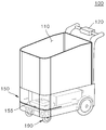
도 1은 본 발명의 일 실시예에 의한 카트의 외관을 보여주는 도면이다.
도 2는 본 발명의 일 실시예에 의한 카트(100)의 제어모듈(150)을 구성하는 구성요소들을 도시한 도면이다.
도 3은 본 발명의 일 실시예에 의한 전원공급장치(300)의 구성을 보여주는 도면이다.
도 4는 본 발명의 일 실시예에 의한 하나의 카트가 전원공급장치에 연결된 구성을 보여주는 도면이다.
도 5 및 도 6은 본 발명의 다른 실시예에 의한 둘 이상의 카트가 전원공급장치에 연결된 구성을 보여주는 도면이다.
도 7은 본 발명의 일 실시예에 의한 전원공급장치가 카트들에 대해 우선순위를 설정하는 과정을 보여주는 도면이다.
도 8은 본 발명의 일 실시예에 의한 카트의 증감에 따라 우선 순위를 변경하는 과정을 보여주는 도면이다.
도 9는 본 발명의 일 실시예에 의한 카트 충전의 예시를 보여주는 도면이다.
도 10은 본 발명의 일 실시예에 의한 카트의 충전 속도를 반영하여 우선 순위를 산출하는 과정을 보여주는 도면이다.
도 11은 본 발명의 일 실시예에 의한 카트의 충전부와 전원 연결부의 세부적인 구성을 보여주는 도면이다.
도 12는 본 발명의 일 실시예에 의한 제어모듈들의 전원연결부들이 서로 연결된 실시예를 보여주는 도면이다.
도 13 내지 도 15는 본 발명의 일 실시예에 의한 다수의 충전열의 맨 마지막 카트가 표시하는 정보를 보여주는 도면이다.
도 16은 본 명세서의 다른 실시예에 의한 각각의 충전열의 카트들의 인터페이스부가 특정 충전열을 지시하는 실시예를 보여준다.
도 17은 본 발명의 실시예에 의한 전원공급장치가 카트들의 충전열 결합 상태와 충전 상태를 모니터링하는 과정을 보여준다.1 is a view showing the appearance of a cart according to an embodiment of the present invention.
2 is a view showing the components constituting the
3 is a diagram showing the configuration of a
4 is a view showing a configuration in which one cart is connected to a power supply device according to an embodiment of the present invention.
5 and 6 are views showing a configuration in which two or more carts are connected to a power supply according to another embodiment of the present invention.
7 is a diagram illustrating a process of setting priorities for carts by a power supply according to an embodiment of the present invention.
8 is a view showing a process of changing the priority according to the increase or decrease of the cart according to an embodiment of the present invention.
9 is a view showing an example of charging a cart according to an embodiment of the present invention.
10 is a view showing a process of calculating the priority by reflecting the charging speed of the cart according to an embodiment of the present invention.
11 is a diagram showing a detailed configuration of a charging unit and a power connection unit of a cart according to an embodiment of the present invention.
12 is a diagram showing an embodiment in which power connection parts of control modules according to an embodiment of the present invention are connected to each other.
13 to 15 are views showing information displayed by the last cart of a plurality of charging trains according to an embodiment of the present invention.
16 shows an embodiment in which the interface units of the carts of each charging heat instruct a specific charging heat according to another embodiment of the present specification.
17 is a view illustrating a process in which the power supply device according to an embodiment of the present invention monitors the state of charging heat coupling and charging state of carts.
이하, 도면을 참조하여 본 발명의 실시예에 대하여 본 발명이 속하는 기술 분야에서 통상의 지식을 가진 자가 용이하게 실시할 수 있도록 상세히 설명한다. 본 발명은 여러 가지 상이한 형태로 구현될 수 있으며 여기에서 설명하는 실시예에 한정되지 않는다.Hereinafter, embodiments of the present invention will be described in detail with reference to the drawings so that those of ordinary skill in the art may easily implement the present invention. The present invention may be implemented in various forms and is not limited to the embodiments described herein.
본 발명을 명확하게 설명하기 위해서 설명과 관계없는 부분은 생략하였으며, 명세서 전체를 통하여 동일 또는 유사한 구성요소에 대해서는 동일한 참조 부호를 붙이도록 한다. 또한, 본 발명의 일부 실시예들을 예시적인 도면을 참조하여 상세하게 설명한다. 각 도면의 구성요소들에 참조부호를 부가함에 있어서, 동일한 구성요소들에 대해서는 비록 다른 도면상에 표시되더라도 가능한 한 동일한 부호를 가질 수 있다. 또한, 본 발명을 설명함에 있어, 관련된 공지 구성 또는 기능에 대한 구체적인 설명이 본 발명의 요지를 흐릴 수 있다고 판단되는 경우에는 그 상세한 설명은 생략할 수 있다.In order to clearly describe the present invention, parts irrelevant to the description are omitted, and the same reference numerals are attached to the same or similar components throughout the specification. Further, some embodiments of the present invention will be described in detail with reference to exemplary drawings. In adding reference numerals to elements of each drawing, the same elements may have the same numerals as possible even if they are indicated on different drawings. In addition, in describing the present invention, when it is determined that a detailed description of a related known configuration or function may obscure the subject matter of the present invention, a detailed description thereof may be omitted.
본 발명의 구성 요소를 설명하는 데 있어서, 제 1, 제 2, A, B, (a), (b) 등의 용어를 사용할 수 있다. 이러한 용어는 그 구성 요소를 다른 구성 요소와 구별하기 위한 것일 뿐, 그 용어에 의해 해당 구성 요소의 본질, 차례, 순서 또는 개수 등이 한정되지 않는다. 어떤 구성 요소가 다른 구성요소에 "연결", "결합" 또는 "접속"된다고 기재된 경우, 그 구성 요소는 그 다른 구성요소에 직접적으로 연결되거나 또는 접속될 수 있지만, 각 구성 요소 사이에 다른 구성 요소가 "개재"되거나, 각 구성 요소가 다른 구성 요소를 통해 "연결", "결합" 또는 "접속"될 수도 있다고 이해되어야 할 것이다.In describing the constituent elements of the present invention, terms such as first, second, A, B, (a), (b) may be used. These terms are only for distinguishing the component from other components, and the nature, order, order, or number of the component is not limited by the term. When a component is described as being "connected", "coupled" or "connected" to another component, the component may be directly connected or connected to that other component, but other components between each component It is to be understood that is "interposed", or that each component may be "connected", "coupled" or "connected" through other components.
또한, 본 발명을 구현함에 있어서 설명의 편의를 위하여 구성요소를 세분화하여 설명할 수 있으나, 이들 구성요소가 하나의 장치 또는 모듈 내에 구현될 수도 있고, 혹은 하나의 구성요소가 다수의 장치 또는 모듈들에 나뉘어져서 구현될 수도 있다.In addition, in implementing the present invention, components may be subdivided and described for convenience of description, but these components may be implemented in one device or module, or one component may be a plurality of devices or modules. It can also be implemented by being divided into.
이하, 본 명세서에서 사용자를 추종하며 자율적으로 이동하는 장치들, 또는 사용자의 제어에 따라 보조적으로 이동하는 장치들을 스마트 카트, 카트로봇 혹은 줄여서 카트라고 한다. 카트는 대형 마트나 백화점 등 매장 내에서 사용할 수 있다. Hereinafter, in the present specification, devices that follow a user and autonomously move, or devices that auxiliaryly move according to the user's control are referred to as a smart cart, a cart robot, or a cart for short. Carts can be used in stores such as large marts and department stores.
또는 공항이나 항만과 같이 여행객들이 많은 공간 내에서 카트가 사용될 수 있다. 그리고 카트는 골프장과 같은 레저 공간에서도 사용될 수 있다. 그 외에도 카트는 사용자의 위치를 추적하여 사용자를 따르면서 소정의 보관 공간을 가지는 모든 장치를 포함한다. Alternatively, a cart can be used in a space with many travelers, such as an airport or a port. And the cart can also be used in a leisure space such as a golf course. In addition, the cart includes all devices having a predetermined storage space while tracking the user's location and following the user.
또한 카트는 병원에서 특정한 약품 또는 치료 장비를 수송하는 장치를 포함한다. 또한 카트는 환자를 이송하는 침대와 같은 장치를 포함한다. 그외에도 카트는 대형화된 공장에서 상품을 수송하기 위해 상품을 적재하여 이동하는 장치를 포함한다. 일 실시예로 카트의 형태를 가지지만, 이를 확장하면 물건을 수납하는 수납 공간을 가지거나, 사람이 타거나 누울 수 있는 공간을 포함하는 로봇도 본 발명의 실시예가 적용된다. 따라서, 카트는 소정의 수납 공간을 가지며 사용자가 제어하는 로봇과 같은 실시예들을 모두 포함한다. Carts also contain devices for transporting specific medications or treatment equipment from the hospital. The cart also includes a bed-like device to transport the patient. In addition, the cart includes a device that loads and moves goods to transport goods in a large-sized factory. An embodiment of the present invention is also applied to a robot having a cart shape as an example, but having a storage space for storing objects or including a space in which a person can ride or lie down when expanded. Accordingly, the cart has a predetermined storage space and includes all embodiments such as a robot controlled by a user.
또는 카트는 사용자가 밀거나 당기는 힘을 반영하여 사용자의 힘을 보조하여 전기 에너지로 이동할 수 있다. Alternatively, the cart may reflect a force pushed or pulled by the user to assist the user's force and move to electric energy.
즉, 본 명세서에서 카트는 충전된 전기에너지를 이용하여 자율적으로 이동하거나, 혹은 사용자의 제어에 따라 반자율적으로 이동하거나, 사용자의 근력을 보조하여 이동하는 모든 장치를 포함한다. That is, in the present specification, the cart includes all devices that move autonomously using charged electric energy, move semi-autonomously under the user's control, or move by assisting the user's muscle strength.
본 발명의 일 실시예에 의한 카트들의 충전 방식으로 카트들이 전기적으로 연결된 상태에서 하나 또는 둘 이상의 전원공급장치가 전원을 공급하는 방식을 포함한다. The charging method of carts according to an embodiment of the present invention includes a method in which one or more power supply devices supply power while the carts are electrically connected.
특히, 하나의 전원공급장치가 다수의 카트들에게 전원을 공급하는 실시예로 캐스캐이드 방식(Cascade mechanism)을 적용할 수 있다. 이 방식은 다수의 카트가 하나의 전원공급장치로부터 전원을 공급받는 구성이다. 예를 들어 카트가 직렬로 연결되며 어느 하나의 카트가 전원공급장치에 연결되면 해당 카트에 연결된 다른 카트들도 전원공급장치로부터 전원을 공급받을 수 있는 구성이다. In particular, a cascade mechanism may be applied as an embodiment in which one power supply device supplies power to a plurality of carts. In this method, multiple carts are supplied with power from a single power supply. For example, if a cart is connected in series and one cart is connected to a power supply, other carts connected to the cart can also receive power from the power supply.
또한, 본 발명의 다른 실시예에 의한 전원 공급 방식으로 하나의 전원 공급장치에 둘 이상의 카트가 병렬로 배치되는 패러럴 방식(Parallel mechanism)을 적용할 수 있다. 이 경우, 하나의 전원 공급장치가 둘 이상의 전원 단자를 포함하며, 둘 이상의 직렬로 연결된 카트들에게 하나의 전원 공급장치가 전원을 공급한다. In addition, as a power supply method according to another embodiment of the present invention, a parallel mechanism in which two or more carts are arranged in parallel to one power supply device may be applied. In this case, one power supply includes two or more power terminals, and one power supply supplies power to two or more carts connected in series.
예를 들어 전원 공급장치의 제1단자는 3 개의 제1카트-제2카트-제3카트들과 캐스캐이드 방식으로 연결된다. 그리고 동일한 전원 공급장치의 제2단자는 4개의 제4카트-제5카트-제6카트-제7카트들과 캐스캐이드 방식으로 연결된다. 전원 공급장치는 두 개의 단자에 연결된 7개의 카트들의 충전 할당량을 각각 산출할 수 있다.For example, the first terminal of the power supply is connected to the three first cart-second cart-third carts in a cascade manner. And the second terminal of the same power supply is connected to the four fourth cart-fifth-cart-sixth-cart-seventh carts in a cascade manner. The power supply can calculate the charge quota for each of the seven carts connected to the two terminals.
도 1은 본 발명의 일 실시예에 의한 카트의 외관을 보여주는 도면이다. 1 is a view showing the appearance of a cart according to an embodiment of the present invention.
카트(100)는 수납부(110)와 핸들 어셈블리(120), 제어모듈(150), 이동부(190)로 구성된다. 수납부(110)는 사용자에 의해 사물이 수납되거나 적재되는 공간이다. 핸들 어셈블리(120)는 사용자가 카트(100)를 수동으로 이동을 제어하거나, 반자동으로 이동을 제어할 수 있도록 한다. The
핸들 어셈블리(120)를 이용하여 사용자는 카트(100)를 전후로 밀거나 방향을 변경할 수 있다. 제어모듈(150)는 카트(100)의 이동을 제어한다. 카트의 이동 방식이 반자동인 경우, 제어모듈(150)은 사용자가 카트를 밀거나 당기는 방향으로 전기 에너지를 이용하여 카트(100)가 이동할 수 있도록 한다. Using the
또한, 카트의 이동 방식이 자동인 경우, 제어모듈(150)는 카트(100)가 사용자를 추종하여 이동할 수 있도록 카트(100)의 이동을 제어한다. In addition, when the moving method of the cart is automatic, the
제어모듈(150)은 이동부(190)를 제어할 수 있다. 또한 카트(100)의 여러 영역에 사용자의 추종을 위한 사용자 위치를 추적하는 측위 센서가 배치될 수 있다. 또한 카트(100)의 여러 영역에는 주변의 장애물을 센싱하기 위한 장애물 센서가 배치될 수 있다.The
장애물 센서는 카트(100)의 하단에 배치될 수 있다. 예를 들어 155에서 지시되는 영역에 카트의 전/좌/우/후방의 장애물을 센싱하기 위해 다수의 장애물 센서(220)들이 배치될 수 있다. 일 실시예로 전면/양측면과 같이 카트(100)가 이동하는 방향으로 장애물 센서가 배치될 수 있다. 또는 카트(100)가 후진할 경우, 전면 및 후면, 양측면에 장애물 센서가 배치될 수 있다. The obstacle sensor may be disposed at the bottom of the
또한, 다른 카트와 전기적으로 연결되는 전원연결부 역시 카트(100)에 배치될 수 있다. 전원연결부는 일종의 전기적 연결을 가능하게 하는 커넥터 또는 단자를 일 실시예로 한다. 또한, 카트 간의 결합 방식에 따라 전원연결부는 수납부(110) 내에 위치할 수도 있고 카트(100)의 외부면에 배치될 수도 있다. 또는 155에서 지시되는 영역에 전원연결부가 배치될 수 있다. In addition, a power connection part electrically connected to another cart may also be disposed on the
전원연결부의 물리적 위치는 다양하게 배치될 수 있으며, 논리적 구성은 제어모듈(150) 내의 충전부(210)와 함께 구성된다.The physical location of the power connection unit may be arranged in various ways, and the logical configuration is configured with the charging
그 외에 사용자의 위치를 센싱하는 측위 센서 역시 카트(100)의 상단 또는 외부 측면 등에 배치될 수 있다. 장애물 센서 또는 측위 센서의 위치나 종류 등은 카트의 외관의 구성에 따라 다양하게 변경될 수 있으며 본 발명이 이에 한정되지 않는다. In addition, a positioning sensor that senses the user's position may also be disposed on the top or outer side of the
그리고 센서들의 위치와 무관하게 제어모듈(150)은 센서들을 제어하거나 센서들이 센싱한 정보를 활용한다. 즉, 센서들, 전원연결부 등은 물리적 위치에 상관없이 논리적으로 제어모듈(150)의 구성요소이다. In addition, regardless of the positions of the sensors, the
또한, 핸들 어셈블리(120)에는 사용자에게 소정의 정보를 출력하는 인터페이스부가 배치될 수 있으며, 인터페이스부 역시 제어모듈(150)의 제어를 받는 구성요소가 될 수 있다.In addition, an interface unit that outputs predetermined information to a user may be disposed on the
또한, 카트(100)는 원격에 배치되어 사용자가 소지하는 송신모듈의 위치를 확인하여 사용자를 추종하며 이동할 수 있다. 또는 카트(100)는 원격에 배치된 고정형 송신모듈의 위치를 확인하여 카트(100)의 현재 위치를 확인할 수 있다. In addition, the
본 발명은 도 1과 같은 구성에 한정되지 않으며 다양하게 구성될 수 있다. The present invention is not limited to the configuration shown in FIG. 1 and may be configured in various ways.
도 2는 본 발명의 일 실시예에 의한 카트(100)의 제어모듈(150)을 구성하는 구성요소들을 도시한 도면이다. 2 is a view showing the components constituting the
도 2는 제어모듈(150)을 구성하는 논리적 구성요소들인 충전부(210), 장애물 센서(220), 인터페이스부(230), 제어부(250), 통신부(280), 전원연결부(290)를 도시한 도면이다. FIG. 2 is a diagram illustrating a
충전부(210)는 배터리를 포함하며 전기 에너지를 누적하여 충전시킨다. 전원연결부(290)에서 제공하는 전원을 이용하여 충전한다. 이때, 제어부(250)의 제어에 따라 충전부(210)는 카트 별로 설정된 충전 할당량에 기반하여 충전한다. The charging
충전 할당량이란 카트들이 충전하도록 할당받은 전원의 크기를 의미한다. 예를 들어, 배터리의 충전 속도나 충전 시간은 충전 전류의 크기에 좌우된다. 따라서, 충전 할당량은 배터리의 충전 전류의 크기를 일 실시예로 한다. 다만, 충전 방식에 따라 충전 할당량은 전류량이 아닌 다른 전기적 특성으로 설정될 수 있으며 본 발명이 이에 한정되는 것은 아니다. 즉, 충전부를 구성하는 배터리의 종류 또는 배터리의 충전 방식에 따라 본 명세서의 충전 할당량은 전류의 크기, 전압의 크기 등 다양한 전기적 특성을 지시할 수 있다.Charging quota refers to the amount of power allocated to the carts to charge. For example, the charging speed or charging time of a battery depends on the magnitude of the charging current. Accordingly, the charge allocation amount is based on the size of the charging current of the battery as an embodiment. However, depending on the charging method, the charging allocation amount may be set to an electrical characteristic other than the current amount, and the present invention is not limited thereto. That is, according to the type of the battery constituting the charging unit or the charging method of the battery, the charging allocation amount in the present specification may indicate various electrical characteristics such as the magnitude of the current and the magnitude of the voltage.
전원공급장치(300)는 각 카트로부터 수신한 충전 요구량 정보와 각 카트의 특성에 기반하여 각 카트별로 충전에 할당한 전기적 에너지의 크기를 설정할 수 있다. 충전 할당량 정보는 충전부(210)의 충전을 위해 카트가 전원공급장치로부터 할당받은 수치적 정보이다. The
일 실시예로 충전 할당량 정보는 각 카트의 충전시 적용되는 전류량의 크기에 대한 정보이다. 각 카트들이 수신한 충전에 할당한 충전 할당량 정보는 카트 별로 상이할 수 있다. 이러한 차이는 카트들의 위치, 충전부(210)의 충전 용량 등에 따라 발생한다.In one embodiment, the charging quota information is information on the amount of current applied when charging each cart. The charge quota information allocated to the charge received by each cart may be different for each cart. This difference occurs depending on the positions of the carts and the charging capacity of the charging
충전부(210)에 전기 에너지가 충전된 상태는 제어부(250)에 의해 확인될 수 있으며, 이 정보는 통신부(280)를 통해 외부의 전원공급장치(300) 또는 다른 카트에게 전송될 수 있다. The state in which the electric energy is charged in the
장애물 센서(220)는 카트의 주변에 배치된 장애물을 센싱한다. The
이동부(190)는 충전부에 충전된 전기 에너지를 이용하여 동력을 제공하여 카트(100)를 이동시킨다. 이동부(190)의 이동은 이동부(190)를 구성하는 휠의 회전속도와 회전한 횟수, 방향 등에 기반하여 카트(100)의 이동 거리나 이동 방향 등을 제어부(250)가 확인할 수 있다. The moving
통신부(280)는 제어모듈(150)의 소프트웨어를 원격에서 업그레이드 할 수 있다. 또는 통신부(280)는 충전부(210)에 전기 에너지가 충전된 상태 또는 카트의 식별 정보 등을 외부로 전송하거나, 다른 카트의 정보를 수신하는 기능을 제공한다. 통신부(280)는 전원공급장치(도 3의 300)에게 카트의 식별 정보와 충전 요구량 정보를 전송하고 전원공급장치(도 3의 300)로부터 충전 할당량 정보를 수신한다. 송수신되는 정보는 충전 요구량에 대한 수치적 정보, 충전에 할당한 충전 할당량에 대한 수치적 정보 등을 일 실시예로 한다. 또는 충전 할당량 정보는 충전에 할당한 전류량의 크기가 될 수 있다. The
인터페이스부(230)는 충전부(210)의 충전량을 사용자가 확인할 수 있도록 정보를 출력한다. 그외에도 소정의 광고가 출력될 수 있으며, 통신부(280)는 광고나 메시지 등 인터페이스부(230)에 출력할 정보를 수신할 수 있다. 또한 통신부(280)는 수납부(110)에 수납된 상품의 정보를 외부의 서버로 전송하여 무인 매장 내에서 결제를 용이하게 할 수 있다. The
제어부(250)는 다른 구성요소들을 제어한다. 제어부(250)는 배터리 관리 시스템(Battery Management System)을 포함한다. 또한, 제어부(250)는 충전회로를 더 포함하며, 충전을 관리하고 입력된 전원 중 일부를 다른 카트로 전달하기 위해 전원 연결부(290)를 제어할 수 있다. The
특히, 제어부(250)는 전원공급장치(도 3의 300)가 설정한 카트 별 충전 할당량 정보, 예를 들어 충전 전류량을 지시한 정보를 이용하여 충전부(210)의 충전을 제어한다. 충전 할당량(예를 들어 충전 전류량)에 따른 충전의 제어는 제어부(250) 내의 배터리 관리 시스템에 의해 제어될 수 있다. In particular, the
전원연결부(290)는 전원공급장치에 전기적으로 접속한다. 또는 전원연결부(290)는 다른 카트에 전기적으로 접속한다. 도 5 및 도 6, 도 11 및 도 12에서 상세히 살펴본다. The
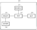
도 3은 본 발명의 일 실시예에 의한 전원공급장치(300)의 구성을 보여주는 도면이다. 전원공급장치(300)는 전기적으로 연결된 하나 이상의 카트들에게 전기 에너지를 공급하는 전원 공급부(330), 외부의 서버 또는 카트로부터 정보를 수신하거나 외부의 서버 또는 카트에게 정보를 송신하는 통신부(380)를 포함한다. 3 is a diagram showing the configuration of a
또한 전원공급장치(300)는 선택적으로 데이터베이스부(310)를 포함하는데, 카트의 식별정보와 해당 카트의 충전시 특성 등에 대한 정보를 저장한다. 제어부(350)는 전술한 구성요소들을 제어한다. In addition, the
전원연결부(390)는 전원공급장치(300) 외부에 배치되어 카트(100)의 전원연결부(290)와 전기적으로 접속한다. 또는, 전원연결부(390)는 일종의 플러그 및 전선으로 구성될 수 있다. 또는 전원연결부(390)는 접속단자의 형태로 구성될 수 있다.The
제어부(350)는 다수의 카트들의 충전 상태나 각 카트들이 전송한 충전 요구량 정보에 따라 카트 별로 가중치를 달리하여 카트들을 충전시킬 수 있다.The
전술한 구성을 적용할 경우, 다수의 카트가 서로 전기적으로 접속하고 어느 하나의 카트만 전원공급장치(100)에 연결되어도 전체 카트들이 충전할 수 있는 캐스캐이드 방식의 충전이 가능하다. In the case of applying the above-described configuration, even if a plurality of carts are electrically connected to each other and only one cart is connected to the
도 3의 전원연결부(390)는 다수가 구성될 수 있다. 이 경우, N 개의 전원연결부(390)는 N개의 열들로 구성된 카트들에게 전원을 공급할 수 있다. The
예를 들어 제1전원연결부는 제1열을 구성하는 5개의 카트들에게 전원을 공급한다. 제2전원연결부는 제2열을 구성하는 3개의 카트들에게 전원을 공급한다. 제3전원연결부는 제3열을 구성하는 4개의 카트들에게 전원을 공급한다. For example, the first power connector supplies power to five carts constituting the first row. The second power connection unit supplies power to the three carts constituting the second row. The third power connector supplies power to the four carts constituting the third row.
그리고 제N전원연결부는 제N열을 구성하는 m개의 카트들에게 전원을 공급한다. 이러한 구성에서 제어부(350)는 각 전원 연결부에 연결된 각각의 열의 카트들의 충전 할당량을 열에 따라 산출할 수 있다. In addition, the Nth power connector supplies power to m carts constituting the Nth row. In this configuration, the
또는 제어부(350)는 모든 전원 연결부에 연결된 모든 열의 카트들의 충전 할당량을 통합하여 산출하고 각각 배분할 수 있다. 제어부(350)는 전원공급장치가 제공할 수 있는 전기에너지의 크기, 카트들의 충전 상태 등을 반영하여 카트 별, 각 열 별로 충전 할당량을 산출한다. Alternatively, the
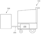
도 4는 본 발명의 일 실시예에 의한 하나의 카트가 전원공급장치에 연결된 구성을 보여주는 도면이다. 하나의 카트(100)가 전원공급장치(300)에 연결되면, 카트(100)의 제어모듈(150)이 충전을 제어한다. 카트(100)의 제어모듈(150) 내의 제어부(250)는 충전회로와 BMS를 포함할 수 있으며, 제어부(250)는 충전부(210)를 제어하여 전원공급장치(300)의 전기에너지를 충전부(210)에 충전시킨다. 4 is a diagram showing a configuration in which one cart is connected to a power supply device according to an embodiment of the present invention. When one
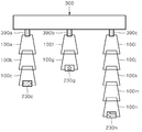
도 5 및 도 6은 본 발명의 다른 실시예에 의한 둘 이상의 카트가 전원공급장치에 연결된 구성을 보여주는 도면이다. 다수의 카트들이 하나의 전원공급장치에 전기적으로 접속하기 위해, 카트(100a, 100b, ..., 100z)들은 순차적으로 배치된다. 5 and 6 are views showing a configuration in which two or more carts are connected to a power supply according to another embodiment of the present invention. In order for a plurality of carts to electrically connect to one power supply, the
일 실시예로 카트의 외관 전면에는 전원공급장치(300)와 연결되거나 다른 카트와 전기적으로 연결되어 전원을 공급받는 전원 수신연결부가 배치될 수 있다. 또는 카트의 외관 후면에는 다른 카트와 전기적으로 연결되어 다른 카트에게 전원을 공급하는 전원송신연결부가 배치될 수 있다. In an embodiment, a power receiving connector connected to the
또는 카트가 서로 중첩되는 네스팅(Nesting) 구조(도 6에 도시)에서는 카트의 제어모듈(150)의 양측면에 전원수신연결부와 전원송신연결부가 배치될 수 있다. 그리고 카트들이 중첩되도록 네스팅 형태로 결합하면 각 카트들의 제어모듈(150)들이 인접하게 배치되어 전기적으로 접속하여 카트들 간에 전원을 공유할 수 있다. 도 6의 경우, 수납부는 카트들이 네스팅 구조로 접속할 때 제어모듈(150)이 배치되지 않은 방향으로 이동될 수 있다. Alternatively, in a nesting structure in which the carts overlap each other (shown in FIG. 6), a power receiving connector and a power transmitting connector may be disposed on both sides of the
도 5 또는 도 6과 같이 다수의 카트들(100a, 100b, ..., 100z)이 접속하고 전원공급장치가 다수의 카트를 충전할 경우 전원공급장치가 공급 가능한 전류량에 따라 카트들의 충전 시간이 증감할 수 있다. 전원공급장치가 공급할 수 있는 전류량은 한정되어 있으므로, 전원공급장치(300)가 동시에 충전할 수 있는 카트의 수는 제한될 수 있다. 또한, 전원공급장치가 카트들에 대해 설정한 우선순위에 따라 일부 카트들만 충전을 위한 전원이 공급된다. 또한 우선 순위가 낮은 카트들은 충전하지 않고 공급된 전원을 다른 카트로 전달한다. 5 or 6, when a plurality of
다수의 카트들은 각각 통신을 수행하는 모듈인 통신부(280)가 배치되며, 통신부(280)는 전원공급장치(300)로부터 각 카트가 필요로 하는 충전 전원에 대한 정보를 수신받고, 이에 따라 제어모듈(150)의 제어부(250)는 충전부(210)의 충전을 제어할 수 있다. Each of the plurality of carts is provided with a
통신부(280)는 블루투스(Bluetooth) 통신 프로토콜이나 전력선 통신 프로토콜을 사용하여 전원공급장치(300)와 정보를 송수신할 수 있다. 또는 통신부(280)는 지그비(Zigbee) 통신 프로토콜을 사용하여 전원공급장치(300)와 정보를 송수신할 수 있다.The
다수의 카트들이 전기적으로 접속하므로, 전원공급장치는 공급 가능한 최대 전류값과 카트들의 수, 또는 긴급 충전이 필요한 카트의 수 등에 따라 각 카트별로 우선순위를 설정할 수 있다. Since a plurality of carts are electrically connected, the power supply may set a priority for each cart according to the maximum current value that can be supplied, the number of carts, or the number of carts requiring emergency charging.
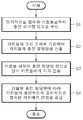
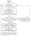
도 7은 본 발명의 일 실시예에 의한 전원공급장치가 카트들에 대해 우선순위를 설정하는 과정을 보여주는 도면이다. 7 is a diagram illustrating a process of setting priorities for carts by a power supply according to an embodiment of the present invention.
전원공급장치(300)의 통신부(380)는 전기적으로 접속된 하나 이상의 카트들로부터 충전요구량 정보를 수신한다(S1). 충전 요구량 정보란 카트의 배터리의 잔여량이나 충전를 해야 하는 용량에 대한 정보를 포함한다. 전기적으로 접속된다는 것은 도 5 또는 도 6과 같이 전원공급장치(300)에 하나의 카트(100a)가 물리적으로 접속하며, 그 다음 카트(100b)가 첫번째 카트(100a)에 물리적으로 접속하여, 이러한 접속이 100c, 100d, ..., 100z 까지 순차적으로 카트들이 연결되는 것을 의미한다. The
그리고 제어부(350)는 카트들의 우선 순위에 기반하여 카트들의 충전 할당량을 산출한다(S2). 우선 순위는 다양한 방식으로 계산될 수 있다. 높은 우선 순위를 가진 카트는 더 짧은 시간 안에 충전된다. 이를 위해 높은 우선 순위를 가진 카트에 더 많은 충전 할당량이 배분된다. 그 결과 높은 우선 순위를 가진 카트는 더 많은 충전 전류량으로 충전부를 충전시킨다.Then, the
일 실시예로, 각 카트들이 전송하는 충전 요구량 정보에 따라 제어부(350)는 각 카트들의 우선 순위를 산출하고 이에 기반하여 충전 할당량을 산출할 수 있다. 충전 요구량이 높은 카트들은 배터리의 충전 상태가 저충전 상태이므로, 빠른 충전이 필요한 카트이다. 따라서, 제어부(350)는 이들 카트들의 우선 순위를 높여서 많은 전류량이 많이 할당되도록 충전 할당량을 설정한다. In one embodiment, the
또는 각 카트들이 접속된 순서, 즉 카트들의 접속 순서 정보에 따라 제어부(350)는 우선 순위를 산출하여 충전 할당량을 산출할 수 있다. 접속 순서 정보란, 전원공급장치로부터 인접하게 접속한 순서에 따라 제어부(350)는 카트의 접속 순서 정보를 증가시켜 설정한다. Alternatively, the
예를 들어, 도 5 또는 도 6에서 첫번째 카트(100a)의 접속 순서 정보는 1, 두번째 카트(100b)의 접속 순서 정보는 2, 등으로 설정할 수 있다. 가장 끝에 있는 카트(100z)의 접속 순서가 26이 될 수 있다. For example, in FIG. 5 or FIG. 6, the access order information of the
카트의 접속 순서가 높을수록 사용자에 의해 먼저 사용될 가능성이 높다. 왜냐하면 가장 끝쪽에 배치된 카트들의 순서에 따라 사용자가 카트들을 사용하기 때문이다. 따라서 카트의 접속 순서가 높을수록 카트가 곧 사용될 가능성이 높으므로 빠른 충전이 필요하다. 따라서 제어부(350)는 접속 순서가 높은 카트의 충전 할당량을 높이 설정한다. The higher the access order of the cart is, the more likely it is to be used by the user first. This is because the user uses the carts according to the order of the carts arranged at the far end. Therefore, the higher the cart connection order, the more likely it is that the cart will be used soon, so fast charging is required. Accordingly, the
이를 반영하여 제어부(350)는 카트들의 접속 순서가 높을 수록 충전에 있어서의 우선 순위 역시 높은 순위를 가져야 한다. 따라서, 제어부(350)는 충전 할당량에 따라 접속 순서 정보가 높은 카트에게 공급할 충전 할당량을 증가시킬 수 있다. 이로 인해, 접속 순서 정보가 높은 카트는 증가된 충전 전류량에 기반하여 충전을 수행한다. Reflecting this, the
또는 제어부(350)는 우선 순위를 설정함에 있어서 데이터베이스부(310)에 저장된 각 카트의 충전 시간을 이용할 수 있다. 즉, 카트 각각이 가지는 충전 특성에 따라 충전 할당량을 달리 설정할 수 있다. Alternatively, the
다양한 방식으로 제어부(350)가 각 카트들의 우선 순위를 산출하고 카트들의 충전 할당량을 산출한 후, 통신부는 카트들 각각의 충전 할당량 정보를 각각의 카트들에게 각각 전송한다(S3). 이후 전원 공급부(330)는 산출된 충전 할당량에 따라 카트들이 충전하도록 물리적으로 접속된 카트(100a)에게 전원을 공급한다(S4). After the
첫번째 카트(100a)는 할당된 충전 할당량만큼만 첫번째 카트(100a)의 충전부를 충전하도록 전원을 공급하고 나머지는 후속하는 카트(100b)에게 전달한다. 첫번째 카트(100a)는 사용할 가능성이 가장 낮으므로 다른 카트들이 우선 충전될 수 있도록 전원의 공급 기능만을 제공할 수 있다. The
이와 같이 각각의 카트들(100a, 100b, ..., 100z)은 충전 할당량에 대한 정보를 수신하므로, 카트들의 제어부(250)는 전원연결부(290)를 통해 인가된 전원 중에서 할당된 전류량 만큼만 충전부(210)를 충전하는데 사용하고, 나머지는 다른 카트들에게 전달할 수 있다. As described above, since each of the
도 8은 본 발명의 일 실시예에 의한 카트의 증감에 따라 우선 순위를 변경하는 과정을 보여주는 도면이다. 8 is a view showing a process of changing the priority according to the increase or decrease of the cart according to an embodiment of the present invention.
전원공급장치(300)에 하나 이상의 카트들이 접속한 상태이며, 전원공급장치(300)는 첫번째 카트에게 전원 공급을 유지한다(S11). 물론 각 카트들은 충전 할당량 정보를 수신한 상태이다. 첫번째 카트는 할당된 충전 전류량만큼만 충전에 사용하고, 전원을 후속하여 접속한 다른 카트에게 제공한다. 만약, 첫번째 카트가 충전이 완료된 경우, 첫번째 카트는 일종의 플러그와 같이 후속하여 접속한 다른 카트와 전원공급장치(300)를 전기적으로 연결한다. One or more carts are connected to the
그리고 일정한 시간 간격으로, 또는 실시간으로, 전원공급장치(300)는 카트들로부터 정보를 수신한다(S12). 전원공급장치(300)가 수신하는 정보는 각 카트들의 잔류 배터리 용량 상태에 관한 정보, 새로운 카트가 추가로 접속하거나, 혹은 접속했던 카트가 접속에서 탈착한 정보가 될 수 있다. 또는 접속한 카트가 충전이 완료되었음을 알리는 충전 완료 정보 역시 전원공급장치(300)가 카트들로부터 수신한다. And at regular time intervals or in real time, the
수신한 정보들을 취합한 결과, 전원공급장치(300)의 제어부(350)는 현재 접속된 카트들 중에서 미충전된 카트의 수(UNCHARGED_CART_NUM)를 확인한다. 그리고, 전원공급장치(300)의 제어부(350)는 미충전된 카트의 수가 최대 충전이 가능한 카트의 수(FULL_CHARGING_CART_NUM) 이하인지 확인한다(S13). As a result of collecting the received information, the
최대 충전이 가능한 카트의 수(FULL_CHARGING_CART_NUM)는 전원공급장치(300)의 전기용량과 카트의 배터리 용량 등에 따라 가변될 수 있다. 예를 들어, 전원공급장치(300)가 1500W이며 60V/30A로 전원을 공급할 경우, 800Wh 급 배터리를 사용하는 카트인 경우 6시간 충전을 목표로 15대를 동시 충전을 할 수 있다. The maximum number of carts that can be charged (FULL_CHARGING_CART_NUM) may vary depending on the electric capacity of the
따라서, 충전 시간이나 충전 용량에 따라 최대 충전이 가능한 카트의 수(FULL_CHARGING_CART_NUM)가 결정된다. 그리고 이보다 작은 수로 미충전된 카트가 전원제공장치(300)에 접속한 상태이면 별도의 우선 순위 계산 없이 미충전된 모든 카트들에게 최대 전류량을 설정하여 카트들을 충전할 수 있다. Therefore, the maximum number of carts that can be charged (FULL_CHARGING_CART_NUM) is determined according to the charging time or charging capacity. And, if the carts that are not charged in a smaller number are connected to the
예를 들어, 최대 충전이 가능한 카트의 수(FULL_CHARGING_CART_NUM)가 5인 경우 5대 이하로 미충전된 카트들이 접속된 경우, 제어부(350)는 우선 순위의 설정 없이 최대 전류량(최대 충전 할당량)으로 카트들을 급속 충전시킬 수 있다. 이를 위해 제어부(350)는 미충전 카트들에게 최대 할당량, 즉 최대 전류량을 설정한다(S14). For example, when the maximum number of carts that can be charged (FULL_CHARGING_CART_NUM) is 5, when 5 or less uncharged carts are connected, the
그 결과, 전원공급장치(300)의 통신부(390)는 미충전 카트들에게 급속 충전할 것을 지시하는 메시지를 전송하고, 메시지를 수신한 미충전 카트들은 최대 전류량으로 급속 충전한다. 최대 전류량은 다양하게 설정될 수 있다. As a result, the
한편, S13에서 FULL_CHARGING_CART_NUM < UNCHARGED_CART_NUM 인 경우, 전원제공장치(300)의 제어부(350)는 카트 별 우선 순위를 계산한다(S15). 그리고, 전원제공장치(300)의 제어부(350)는 우선 순위에 기반하여 카트별 충전 할당량을 계산한다(S16). Meanwhile, when FULL_CHARGING_CART_NUM <UNCHARGED_CART_NUM in S13, the
즉, 제어부(350)는 전원공급장치에 하나 이상의 카트가 추가 접속하거나 하나 이상의 카트가 접속을 중단할 경우, 전원공급장치에 접속을 유지하는 모든 카트들의 접속 순서 정보 및 우선 순위를 재산출하여 충전 할당량을 재산출한다. That is, when one or more carts are additionally connected to the power supply or one or more carts are disconnected, the
물론 이 과정에서 각 카트의 현재 배터리 용량 상태 정보도 반영한다. 전원제공장치(300)의 제어부(350)는 충전이 완료된 카트의 충전 할당량을 0으로 설정하여 충전을 종료시키고, 충전이 완료된 카트는 전원을 후속하는 카트에 전달하는 기능을 제공한다. Of course, this process also reflects the current battery capacity status information of each cart. The
전원제공장치(300)의 통신부(390)는 계산된 충전 할당량을 각 카트들에게 전송하고(S17), 이에 따라 각 카트들의 제어부(250)는 할당된 충전 전류량으로 충전부(210)를 충전한다. The
전원제공장치(300)의 제어부(350)는 도 8에 도시된 충전 알고리즘을 통해 카트 별 충전 할당량을 계산할 수 있다. 전원제공장치(300)의 제어부(350)는 각 카트들이 접속하거나 탈착될 경우에 카트의 충전 할당량을 새롭게 세팅한다. 전원제공장치(300)의 제어부(350)는 전원 공급기의 공급 전류가 허용하는 카트의 수(FULL_CHARGING_CART_NUM)까지는 각 카트에 대해 최대 충전 전류로 세팅한다. The
반면, 전원제공장치(300)의 제어부(350)는 허용 최대 충전 전류를 넘는 카트의 수(UNCHARGED_CART_NUM)가 접속할 시 가변적으로 충전 전류를 세팅한다. On the other hand, the
이 과정에서 전원제공장치(300)의 제어부(350)는 기준 배터리 용량을 설정하고, 기준 배터리 용량보다 적은 용량의 배터리를 가진 카트들을 높은 우선 순위로 충전할 수 있다. 또한 전원제공장치(300)의 제어부(350)는 기준 배터리 용량보다 적은 용량의 배터리를 가진 카트가 많을 경우 뒤쪽(접속 순서 정보가 높음)에 있는 카트를 최우선 순위로 충전할 수 있다. 즉, 전원제공장치(300)의 제어부(350)는 뒤쪽에 배치된 카트를 우선하여 충전한다. In this process, the
도 9는 본 발명의 일 실시예에 의한 카트 충전의 예시를 보여주는 도면이다. 9 is a view showing an example of charging a cart according to an embodiment of the present invention.
카트들(100a~100j)들이 전원공급장치(300)에 순차적으로 접속된 상태이다. 카트 별로 쓰여진 1, 2, ..., 10은 각 카트의 접속 순서 정보이다. 그리고 카트 내에는 남은 배터리 용량이 표시되어 있다.
전원제공장치(300)의 제어부(350)는 기준 배터리 용량을 200Wh로 설정한 상태이다. 따라서, 200Wh보다 낮은 카트들(100d, 100f, 100h, 100j)을 우선 충전한다. 이들 카트들의 접속 순서 정보는 각각 4, 6, 8, 10이다. The
각 카트별로 접속 순서 정보에 따라 가중치(weight number)를 부여할 수 있다. 예를 들어 첫번째 카트(100a)는 접속 순서 정보가 1이므로 가중치를 1.0으로 설정한다. 두번째 카트(100b)는 접속 순서 정보가 2이므로 가중치를 1.1로 설정한다. 이와 같이 접속 순서 정보의 증가에 따라 가중치를 0.1씩 증가한 결과 9번째 카트(100i)는 1.8, 10번째 카트(100j)는 1.9로 가중치가 설정된다. 도 9의 실시예에서 전원공급장치(300)는 전류량의 크기로 충전 할당량을 계산한다. A weight number may be assigned to each cart according to access order information. For example, since the access order information of the
전원공급장치(300)의 공급 전류가 30A인 경우, 다음과 같이 4 개의 카트(100d, 100f, 100h, 100j)을 우선적으로 충전하기 위한 전류량을 다음과 같이 산출한다. 4 개의 카트(100d, 100f, 100h, 100j)들 각각의 가중치인 1.3, 1.5, 1.7, 1.9를 수학식 1과 같이 적용한다. When the supply current of the
[수학식 1][Equation 1]
공급 전류 = 단위 전류 x (충전할 카트들의 가중치들의 합)Supply current = unit current x (sum of weights of carts to be charged)
30A = 단위 전류 x (1.3 + 1.5 + 1.7 + 1.9)30A = unit current x (1.3 + 1.5 + 1.7 + 1.9)
단위 전류: 4.6875 AUnit current: 4.6875 A
산출된 단위 전류를 4 개의 카트(100d, 100f, 100h, 100j)들 각각의 가중치인 1.3, 1.5, 1.7, 1.9에 각각 곱하면 4 개의 카트에 설정되는 충전 전류량은 다음과 같다,When the calculated unit current is multiplied by the weights of each of the four carts (100d, 100f, 100h, and 100j), 1.3, 1.5, 1.7, and 1.9, the charging current amount set for the four carts is as follows,
4번째 카트(100d)에 설정된 충전 전류량: 6.09375 A (= 4.6875 x 1.3)Charge current set for 4th cart (100d): 6.09375 A (= 4.6875 x 1.3)
6번째 카트(100f)에 설정된 충전 전류량: 7.03125 A (= 4.6875 x 1.5)Charge current set for 6th cart (100f): 7.03125 A (= 4.6875 x 1.5)
8번째 카트(100h)에 설정된 충전 전류량: 7.96875 A (= 4.6875 x 1.7)Charge current set for 8th cart (100h): 7.96875 A (= 4.6875 x 1.7)
10번째 카트(100j)에 설정된 충전 전류량: 8.90625 A (= 4.6875 x 1.9)Charge current set for 10th cart (100j): 8.90625 A (= 4.6875 x 1.9)
위와 같이 설정된 충전 전류량을 전원공급장치(300)가 카트들에게 전송하면, 각 카트들은 설정된 충전 전류량에 따라 충전을 수행한다. 충전 전류량을 0으로 전송받은 카트들은 충전을 수행하지 않고 전원을 후속하는 카트들에게 전달하는 기능을 수행한다. When the
도 9의 실시예와 같이 전원공급장치(300)는 카트의 잔류 배터리 용량, 카트의 위치 등을 반영하여 실제 충전 전류량(충전 할당량)을 산출할 수 있다.As in the embodiment of FIG. 9, the
또한, 도 9의 실시예에서 새로운 카트가 마지막 카트(100j) 뒤에 접속하였고, 새로운 카트의 배터리에 남아있는 배터리 용량이 매우 낮은 수준(예를 들어 기준 배터리 용량의 10% 이하)인 경우, 새로운 카트는 전원공급장치(300)에게 급속 충전을 요청하는 메시지를 송신할 수 있다. In addition, in the embodiment of FIG. 9, when a new cart is connected after the
전원공급장치(300)의 통신부(380)가 급속 충전을 요청하는 메시지를 수신하면, 전원제공장치(300)의 제어부(350)는 급속 충전을 요청하는 메시지를 송신한 카트에게 최대 충전 전류량을 할당하도록 우선 순위를 변경한다. 예를 들어, 전술한 실시예에서 새로 접속한 카트에게 10 A를 할당하기 위해, 새로 접속한 카트의 가중치를 3.2로 설정하고 수학식 2와 같이 계산하면, 새로 접속한 카트에게 10A를 할당할 수 있다. When the
[수학식 2][Equation 2]
30A = 단위 전류 x (1.3 + 1.5 + 1.7 + 1.9 + 3.2 )30A = unit current x (1.3 + 1.5 + 1.7 + 1.9 + 3.2 )
새로 계산된 단위 전류: 3.125 ANew calculated unit current: 3.125 A
제어부(350)는 산출된 단위 전류를 5 개의 카트(100d, 100f, 100h, 100j, 새로운 카트)들 각각의 가중치인 1.3, 1.5, 1.7, 1.9, 3.2 에 곱한다. 그 결과 5 개의 카트에 다시 설정되는 충전 전류량은 다음과 같다,The
4번째 카트(100d)에 설정된 충전 전류량: 4.0625 A (=3.125 x 1.3)Charge current set for 4th cart (100d): 4.0625 A (=3.125 x 1.3)
6번째 카트(100f)에 설정된 충전 전류량: 4.6875 A (=3.125 x 1.5)Charge current set for 6th cart (100f): 4.6875 A (=3.125 x 1.5)
8번째 카트(100h)에 설정된 충전 전류량: 5.3125 A (=3.125 x 1.7)Charging current set for the 8th cart (100h): 5.3125 A (=3.125 x 1.7)
10번째 카트(100j)에 설정된 충전 전류량: 5.9375 A (=3.125 x 1.9)Charging current set for the 10th cart (100j): 5.9375 A (=3.125 x 1.9)
새로운 카트에 설정된 충전 전류량 : 10 A(=3.125 x 3.2) Charge current set for new cart: 10 A (=3.125 x 3.2)
도 10은 본 발명의 일 실시예에 의한 카트의 충전 속도를 반영하여 우선 순위를 산출하는 과정을 보여주는 도면이다. 카트에 설치된 배터리의 충전 및 방전 횟수에 따라 동일한 충전 요구량인 경우에도 배터리에 따라 충전 시간이 달라질 수 있다. 10 is a view showing a process of calculating the priority by reflecting the charging speed of the cart according to an embodiment of the present invention. The charging time may vary depending on the battery, even if the charging requirement is the same according to the number of charging and discharging of the battery installed in the cart.
전원공급장치(300)의 통신부(380)는 카트로부터 식별 정보 및 충전 요구량 정보을 수신한다(S21). 그리고 전술한 실시예들에 따라 우선 순위가 설정되면 전원공급장치(300)의 제어부(350)는 카트 별로 충전 할당량을 산출하고, 통신부(380)는 카트 별로 충전 할당량 정보를 전송한다(S22). The
이후 일정한 시간 간격으로 카트로부터 현재 충전 상태 정보를 수신한다(S23). 전원공급장치(300)의 제어부(350)는 앞서 충전 할당량 정보를 전송한 시점과 현재 충전 상태 정보를 수신한 시점, 그리고 충전 할당량에서 해당 카트의 배터리를 충전하는데 소요되는 단위 시간 정보를 이용하여 카트의 충전 시간을 산출한다. 그리고, 데이터베이스부(310)는 카트의 식별 정보와 카트의 충전 시간을 저장한다(S24). Thereafter, current charging status information is received from the cart at regular intervals (S23). The
그리고 제어부(350)는 각각의 카트들의 충전 시간에 따라 우선 순위를 산출하고, 이를 반영한 충전 할당량을 산출한다(S25). 그리고 이에 따라 통신부(380)는 카트 별로 충전 할당량 정보를 전송한다(S26).Then, the
추가적인 실시예로, 데이터베이스부(310)에 저장된 충전 시간과 카트 별로 배분할 충전 할당량을 이용하여 제어부(350)는 각각의 카트들의 예상 충전 시간을 산출한다. 그리고 통신부(380) 산출된 예상 충전 시간을 카트 별로 전송한다. 카트(100)의 인터페이스부(230)는 예상 충전 시간을 출력하고 사용자가 이를 확인할 수 있다.In an additional embodiment, the
도 11은 본 발명의 일 실시예에 의한 카트의 충전부와 전원 연결부의 세부적인 구성을 보여주는 도면이다. 설명의 편의를 위하여 충전에 직접 관여하지 않는 제어모듈의 구성요소들은 도시하지 않았다. 전원연결부(290)는 전원수신연결부(291) 및 전원송신연결부(292)로 구성된다.11 is a diagram showing a detailed configuration of a charging unit and a power connection unit of a cart according to an embodiment of the present invention. For convenience of explanation, components of the control module that are not directly involved in charging are not shown. The
전원수신연결부(291)는 전원공급장치 또는 다른 카트로부터 전원을 공급받는다. 전원송신연결부(292)는 전원수신연결부(291)가 공급받은 전원을 다른 카트로 전달한다. The
스위치(201)는 충전부(210)와 전원수신연결부(291) 사이에 배치되며 제어부(250)의 제어에 따라 온/오프 된다. 충전부(210)의 충전이 완료되면 제어부(250)는 스위치를 오프시킨다. 그리고 통신부(도 2의 280)는 충전 완료 메시지를 전원공급장치(도 3의 300)에게 전송한다. The
정리하면, 통신부(250)가 전원공급장치(300)로부터 카트의 충전 할당량 정보를 수신할 경우, 전원수신연결부(291)가 공급받은 전원의 전류량 중에서 제어부(250)는 할당받은 전류량에 기반하여 충전부(210)를 충전하도록 충전부(210)를 제어할 수 있다. 충전이 완료되면 스위치(201)를 제어하여 전원수신연결부(291)와 충전부(210) 사이의 전기적인 접속을 차단할 수 있다. In summary, when the
도 12는 본 발명의 일 실시예에 의한 제어모듈들의 전원연결부들이 서로 연결된 실시예를 보여주는 도면이다. 3 대의 카트에 각각 배치된 3개의 제어모듈들(150a, 150b, 150c)들이 전기적으로 연결된 구성을 보여준다. 설명의 편의를 위하여 충전에 직접 관여하지 않는 제어모듈의 구성요소들은 도시하지 않았다. 12 is a diagram illustrating an embodiment in which power connection parts of control modules are connected to each other according to an embodiment of the present invention. It shows a configuration in which three
제1제어모듈(150a)의 전원수신연결부(291a)는 다른 카트(미도시) 또는 전원공급장치(미도시)에 전기적으로 연결되어 전원을 공급받는다. 제1제어모듈(150a)의 전원송신연결부(292a)는 제2제어모듈(150b)의 전원수신연결부(291b)에 연결된다. 제1제어모듈(150a)의 전원수신연결부(291a)에서 공급받은 전원은 제1제어모듈(150a)의 전원송신연결부(292a)와 제2제어모듈(150b)의 전원수신연결부(291b)의 전기적 접속에 의해 제2제어모듈(150b)으로 공급된다. The
마찬가지로, 제2제어모듈(150b)의 전원송신연결부(292b)는 제3제어모듈(150c)의 전원수신연결부(291c)에 연결된다. 제2제어모듈(150b)의 전원수신연결부(291b)에서 공급받은 전원은 제2제어모듈(150b)의 전원송신연결부(292b)와 제3제어모듈(150c)의 전원수신연결부(291c)의 전기적 접속에 의해 제3제어모듈(150c)으로 공급된다. Likewise, the
제3제어모듈(150c)의 전원송신연결부(292c)에 다른 카트가 전기적으로 접속할 수 있다. 또는 제3제어모듈(150c)이 마지막 카트인 제3제어모듈(150c)의 전원송신연결부(292c)는 다른 카트가 접속하지 않은 상태가 될 수 있다. Another cart may be electrically connected to the
도 12에서 제1제어모듈(150a)의 스위치(201a)는 오픈된 상태이다. 이는 제1제어모듈(150a)의 충전부(210a)가 충전이 완료되어 더 이상 충전하지 않도록 제어부(250a)가 제어한 결과를 보여준다. 다른 실시예로, 제1제어모듈(150a)의 우선순위가 매우 낮아서 제1제어모듈(150a)의 충전부(210a)를 충전하지 않고 단지 후속하는 카트들의 제어모듈들(150b, 150c)에게 전원을 공급하는 상태이다. In FIG. 12, the
여기서, 제3제어모듈(150c)이 배치된 카트가 마지막 카트인 경우, 즉, 제3제어모듈(150c)의 전원송신연결부(292c)에 다른 카트가 연결되지 않은 경우, 제3제어모듈(150c)의 통신부는 전원공급장치(300)에게 급속 충전을 요청하는 메시지를 전송할 수 있다. 이는 마지막 카트이므로 언제든지 사용자에 의해 탈착되어 사용할 수 있는 카트이므로, 잔류하는 배터리 용량이 일정 수준 이하인 경우, 제3제어모듈(150c)의 통신부는 전원공급장치(300)에게 급속 충전을 요청할 수 있다. Here, when the cart on which the
도 12의 구성에서 제3제어모듈(150c)이 배치된 카트가 사용자에 의해 제2제어모듈(150b)이 배치된 카트와 분리되어 이동하면, 제2제어모듈(150b)이 배치된 카트가 마지막 카트가 된다. 마찬가지로 제2제어모듈(150b)의 통신부는 전원공급장치(300)에게 급속 충전을 요청하는 메시지를 전송할 수 있다.In the configuration of FIG. 12, when the cart in which the
본 발명의 실시예를 적용할 경우, 다수의 카트들의 배터리를 동시에 충전할 수 있다. 이 과정에서 카트의 사용 가능성이나 배터리 잔량 등을 고려하여 우선순위에 따라 충전에 적용될 전류값을 설정할 수 있다. 또한 본 발명의 일 실시예에 의하면 최후방에 배치된 카트를 최우선으로 충전하여 사용자가 즉시 사용할 수 있도록 한다. When applying the embodiment of the present invention, it is possible to simultaneously charge the batteries of a plurality of carts. In this process, a current value to be applied for charging can be set according to priority in consideration of the availability of the cart or the remaining battery capacity. In addition, according to an embodiment of the present invention, the cart disposed at the rear is charged with the highest priority so that the user can use it immediately.
또한, 카트의 인터페이스부(230)는 충전 상태를 표시할 수 있다. 예를 들어, 인터페이스부(230)는 현재 충전부(210)의 충전된 상태로 사용 가능한 시간을 표시할 수 있다. 사용자는 인터페이스부(230)에 표시된 사용 가능한 시간 정보와 사용자의 사용 의도에 따라 카트의 사용 여부를 확인할 수 있다. In addition, the
예를 들어, 하나의 공간에 둘 이상의 전원공급장치가 배치되고, 최후방의 카트가 2대가 있는데, 제1카트는 완전히 방전 후 충전 중인 상태여서 인터페이스부(230)가 사용 가능 시간을 5분으로 표시하고, 제2카트는 충전이 완료되어 인터페이스부(230)가 사용 가능 시간을 3시간으로 표시하면, 사용자는 두 개의 카트 중 제2카트를 선택할 수 있다. For example, two or more power supplies are arranged in one space, and there are two carts at the rear, and the first cart is in a state of charging after being completely discharged, so the
이외에도 인터페이스부(230)는 색상으로 사용 가능함을 알리거나 충전 중임을 알릴 수 있다. 또는 인터페이스부(230)는 음성 메시지로 카트가 사용 가능함을 알리거나 충전 중임을 알릴 수 있다. In addition, the
일 실시예로, 충전을 위해 대기 중인 다수의 충전열의 맨 마지막에 위치하여 바로 사용이 예정된 카트는 해당 카트의 충전 상태 또는 해당 충전열의 충전 상태를 인터페이스부(230)에서 표시할 수 있다. In an embodiment, a cart, which is located at the end of a plurality of charging rows waiting for charging, and is scheduled to be used immediately, may display the charging state of the corresponding cart or the charging state of the corresponding charging row on the
도 13 내지 도 15는 본 발명의 일 실시예에 의한 다수의 충전열의 맨 마지막 카트가 표시하는 정보를 보여주는 도면이다.13 to 15 are views showing information displayed by the last cart of a plurality of charging trains according to an embodiment of the present invention.
다수의 카트들이 다수의 충전열을 형성할 경우, 각각의 충전열은 현재 충전 상태를 카트의 인터페이스부(230)가 출력할 수 있다. 또는, 다수의 충전열 중에서 충전이 완료된 열을 카트의 인터페이스부(230)가 지시할 수 있다. 전원공급장치(300)의 세 개의 전원연결부(390a, 390b, 390c) 각각에 3개열의 카트들이 배치된 상태이다. 제1전원연결부(390a)에 연결된 제1충전열은 4개의 카트들(100a, 100b, 100c, 100d)이 연결된 상태이다. 제2전원연결부(390b)에 연결된 제2충전열은 2개의 카트들(100f, 100g)이 연결된 상태이다. 제3전원연결부(390c)에 연결된 제3충전열은 5개의 카트들(100i, 100j, 100k, 100m, 100n)이 연결된 상태이다.When a plurality of carts form a plurality of charging columns, each charging column may output a current charging state to the
여기서 각 충전열의 마지막에 위치한 카트들(100d, 100g, 100n)은 사용자가 사용을 위해 충전열에서 가장 먼저 탈착시키는 카트들이다. 따라서, 본 명세서의 일 실시예에 따를 경우, 마지막 카트들(100d, 100g, 100n)의 인터페이스부(230)는 충전 상태나 사용 가능 상태를 표시할 수 있다. 예를 들어, 맨 마지막 카트들(100d, 100g, 100n)은 현재 충전 상태를 인터페이스부(230d, 230g, 230n)에서 출력할 수 있다. Here, the
도 14는 본 명세서의 일 실시예에 의한 각각의 충전열의 인터페이스부가 현재 충전 상태를 표시한 것을 보여준다. 도 14의 제1열의 마지막 카트(100d)는 충전이 완료되었음을 알리는 메시지를 인터페이스부(230d)에 표시한다. 14 is a view illustrating an interface unit of each charging train according to an embodiment of the present specification displaying a current charging state. The
한편, 도 14의 제2열의 마지막 카트(100g)는 충전이 완료되지 않아, 50분 사용이 가능하다는 메시지를 인터페이스부(230g)에 출력한다. Meanwhile, the
마찬가지로 도 14의 제3열의 마지막 카트(100n) 역시 충전이 완료되지 않아, 20분 사용이 가능하다는 메시지를 인터페이스부(230n)에 출력한다.Likewise, the
사용자는 각각의 카트들이 출력하는 메시지를 확인하여 충전이 완료된 카트(100d)를 선택할 수 있다. The user may check the message output by each of the carts and select the
또한, 도 14와 달리, 각각의 인터페이스부들은 사용자에게 가장 충전이 많이 이루어진 열을 지시할 수 있다. 예를 들어, 도 14와 같이 제1충전열의 카트(100d)가 충전 완료된 경우, 각 충전열의 인터페이스부가 화살표로 해당 충전열을 지시할 수 있다. In addition, unlike FIG. 14, each of the interface units may indicate to the user the heat in which the most charge is made. For example, as shown in FIG. 14, when the
도 15는 본 명세서의 일 실시예에 의한 각각의 충전열의 카트들의 인터페이스부가 충전 완료된 카트를 지시하는 실시예를 보여준다. 도 15에 제시된 바와 같이, 제1열의 마지막 카트(100d)는 충전이 완료되었으므로, 인터페이스부(230d)는 별모양을 표시한다.15 shows an embodiment in which the interface units of the carts of each of the charging trains indicate a charged cart according to an embodiment of the present specification. As shown in FIG. 15, since the charging of the
한편, 제2열의 마지막 카트(100g)는 충전이 완료되지 않았으므로, 충전이 완료된 제1열을 지시하도록 화살표를 인터페이스부(230g)에 출력한다. Meanwhile, since the
마찬가지로, 제3열의 마지막 카트(100n)는 충전이 완료되지 않았으므로, 충전이 완료된 제1열을 지시하도록 화살표를 인터페이스부(230n)에 출력한다.Similarly, since the
도 15와 같은 구성에서 사용자가 제1열의 마지막 카트(100d)를 제1열에서 탈착하여 사용을 시작하면, 전원공급장치(300)는 각 열의 가장 마지막에 배치된 카트들의 충전상태를 모니터링한 후, 가장 많이 충전된 카트를 식별한다. 그리고 도 16과 같이 각각의 충전열의 마지막 카트들이 가장 많이 충전된 카트의 충전열을 지시한다. 즉, 인터페이스부에 표시된 메시지나 이미지는 충전이 완료된 카트의 충전열을 지시할 수 있고, 가장 충전이 많이 된 카트의 충전열을 지시할 수 있다. In the configuration as shown in FIG. 15, when the user starts using the
도 16은 본 명세서의 다른 실시예에 의한 각각의 충전열의 카트들의 인터페이스부가 특정 충전열을 지시하는 실시예를 보여준다.16 shows an embodiment in which the interface units of the carts of each charging heat instruct a specific charging heat according to another embodiment of the present specification.
도 16은 도 15에서 사용자가 제1충전열의 마지막 카트(100d)를 충전열에서 분리하여 사용하는 경우에 각각의 충전열의 카트들의 인터페이스부가 가장 충전이 많이 된 상태의 카트(100g)의 충전열(제2충전열)을 지시하는 실시예를 보여준다. 도 15의 실시예에서 제1충전열의 마지막 카트(100d)가 충전열에서 분리되면, 전원공급장치(300)는 각 열의 가장 마지막에 배치된 카트들의 충전상태를 모니터링한다. 그리고, 이들 3개의 열의 마지막 카트들(100c, 100g, 100n)의 충전 상태를 확인하여 두번째 열의 마지막 카트(100g)를 선택한다. 선택한 카트는 충전된 량이 가장 높거나, 혹은 완전충전된 상태이다. 16 shows the charging heat of the
그리고 전원공급장치(300)는 각각의 충전열에게 두번째 열의 마지막 카트(100g)를 지시할 것을 알리는 메시지를 제공한다. In addition, the
각 충전열의 카트들의 인터페이스부들(230c, 230g, 230n)은 도 16에 도시된 바와 같이 제2충전열의 마지막 카트(100g)를 지시하도록 이미지 또는 메시지 등을 출력한다. 이러한 과정은 새로운 카트가 충전열 중 어느 한 곳에 접속한 경우에도 반복 실시된다. The
도 17은 본 발명의 실시예에 의한 전원공급장치가 카트들의 충전열 결합 상태와 충전 상태를 모니터링하는 과정을 보여준다. 17 is a view illustrating a process in which the power supply device according to an embodiment of the present invention monitors the state of charging heat coupling and charging state of carts.
전원공급장치(300)는 각각의 충전열에서 카트들의 접속 또는 탈착 또는 충전 상태를 모니터링한다(S31). 이는 카트들이 새롭게 충전열에 접속하거나, 혹은 카트들이 사용자로부터 충전열에서 탈착될 경우, 또는 충전 상태가 달라지는 상황을 모니터링하는 것을 의미한다. The
모니터링 결과 전원공급장치(300)는 카트들의 접속 또는 탈착 또는 충전 상태의 변화가 발생한 것을 확인하면, 각각의 충전열의 카트들의 충전량을 모니터링한다(S32). 그리고 전원공급장치(300)는 가장 높은 충전량 상태를 유지하는 카트의 충전열을 선택한다(S33). 물론, 이 과정에서 하나 이상의 충전열이 선택될 수 있다. As a result of the monitoring, the
그리고 전원공급장치(300)는 각 충전열의 카트들에게 선택한 충전열을 지시하는 메시지를 전송한다(S34). 그 결과 각 충전열의 카트들은 해당 카트의 충전 완료를 표시하거나 혹은 인접한 다른 충전열을 지시하는 메시지 또는 이미지를 인터페이스부에 출력할 수 있다. And the
또한, 전원공급장치(300)는 특정한 충전열에 다수의 카트가 접속하거나, 특정 충전열이 빠른 충전이 이루어지는 등의 충전 또는 접속 상태를 반영하여 사용자에게 특정 충전열의 카트 사용을 추천할 수 있다. 이를 위해 각 카트들의 인터페이스부는 현재 사용이 가능한 상태인지 혹은 사용이 불가능한 상태인지를 출력할 수 있다. In addition, the
도 17을 정리하면, 전원공급장치(300)의 제어부(350)는 N개의 전원 연결부(390)에 연결된 N개의 충전열에서 발생하는 카트의 접속 또는 탈착 또는 충전상태의 변화를 모니터링한다. 그리고 전원공급장치(300)의 제어부(350)는 N개의 충전열 중 M개의 충전열이 충전 완료된 상태임을 나타내는 메시지를 생성한다. 이때 M은 N 보다 작거나 같은 수이다. 그리고 전원공급장치(300)의 통신부(380)는 메시지를 각각의 카트들에게 전송한다. 통신부(380)는 메시지를 모든 카트들에게 전송할 수도 있고. 각 충전열의 맨 마지막 카트들에게만 전송할 수도 있다.In summary, the
도 13 내지 도 17의 실시예를 적용할 경우, 사용자는 충전이 완료되거나 보다 많이 충전된 카트를 식별할 수 있으므로, 사용자의 편의성을 높일 수 있다. When the embodiments of FIGS. 13 to 17 are applied, the user can identify a cart that has been charged or has been charged more, thereby improving user convenience.
본 발명의 실시예를 구성하는 모든 구성 요소들이 하나로 결합되거나 결합되어 동작하는 것으로 설명되었다고 해서, 본 발명이 반드시 이러한 실시예에 한정되는 것은 아니며, 본 발명의 목적 범위 내에서 모든 구성 요소들이 하나 이상으로 선택적으로 결합하여 동작할 수도 있다. 또한, 그 모든 구성 요소들이 각각 하나의 독립적인 하드웨어로 구현될 수 있지만, 각 구성 요소들의 그 일부 또는 전부가 선택적으로 조합되어 하나 또는 복수 개의 하드웨어에서 조합된 일부 또는 전부의 기능을 수행하는 프로그램 모듈을 갖는 컴퓨터 프로그램으로서 구현될 수도 있다. 그 컴퓨터 프로그램을 구성하는 코드들 및 코드 세그먼트들은 본 발명의 기술 분야의 당업자에 의해 용이하게 추론될 수 있을 것이다. 이러한 컴퓨터 프로그램은 컴퓨터가 읽을 수 있는 저장매체(Computer Readable Media)에 저장되어 컴퓨터에 의하여 읽혀지고 실행됨으로써, 본 발명의 실시예를 구현할 수 있다. 컴퓨터 프로그램의 저장매체로서는 자기 기록매체, 광 기록매체, 반도체 기록소자를 포함하는 저장매체를 포함한다. 또한 본 발명의 실시예를 구현하는 컴퓨터 프로그램은 외부의 장치를 통하여 실시간으로 전송되는 프로그램 모듈을 포함한다. Even if all the constituent elements constituting an embodiment of the present invention are described as being combined into one or operated in combination, the present invention is not necessarily limited to these embodiments, and all constituent elements within the scope of the present invention may It can also be selectively combined and operated. In addition, although all the components may be implemented as one independent hardware, a program module that performs some or all functions combined in one or more hardware by selectively combining some or all of the components. It may be implemented as a computer program having Codes and code segments constituting the computer program may be easily inferred by those skilled in the art of the present invention. Such a computer program is stored in a computer-readable storage medium, and is read and executed by a computer, thereby implementing an embodiment of the present invention. The storage medium of the computer program includes a magnetic recording medium, an optical recording medium, and a storage medium including a semiconductor recording element. In addition, the computer program implementing the embodiment of the present invention includes a program module that is transmitted in real time through an external device.
이상에서는 본 발명의 실시예를 중심으로 설명하였지만, 통상의 기술자의 수준에서 다양한 변경이나 변형을 가할 수 있다. 따라서, 이러한 변경과 변형이 본 발명의 범위를 벗어나지 않는 한 본 발명의 범주 내에 포함되는 것으로 이해할 수 있을 것이다.In the above, the embodiments of the present invention have been mainly described, but various changes or modifications may be made at the level of those of ordinary skill in the art. Accordingly, it will be understood that such changes and modifications are included within the scope of the present invention as long as they do not depart from the scope of the present invention.
100: 카트
110: 수납부
120: 핸들 어셈블리
150: 제어모듈
190: 이동부
210: 충전부
250: 제어부
290: 전원연결부
300: 전원공급장치100: cart 110: storage unit
120: handle assembly 150: control module
190: moving part 210: charging part
250: control unit 290: power connection
300: power supply
Claims (20)
상기 카트들의 우선 순위에 기반하여 상기 카트들의 충전 할당량을 산출하는 제어부;
물리적으로 접속된 카트에게 전원을 공급하는 전원 공급부를 포함하며,
상기 통신부는 상기 카트들 각각의 충전 할당량 정보를 상기 카트들에게 각각 전송하는, 다수의 카트에게 전원을 공급하는 전원공급장치.
A communication unit for receiving information on a charging demand amount from one or more electrically connected carts;
A control unit that calculates a charge quota of the carts based on the priority of the carts;
Includes a power supply for supplying power to the cart physically connected,
The communication unit is a power supply device for supplying power to a plurality of carts, each transmitting the charge quota information of each of the carts to the carts.
상기 제어부는 각각의 카트들의 충전 요구량에 따라 상기 우선 순위를 산출하여 상기 충전 할당량을 산출하는, 다수의 카트에게 전원을 공급하는 전원공급장치.
The method of claim 1,
The control unit is a power supply device for supplying power to a plurality of carts, calculating the charge allocation amount by calculating the priority according to the charge request amount of each cart.
상기 제어부는 각각의 카트들의 접속 순서 정보에 따라 상기 우선 순위를 산출하여 상기 충전 할당량을 산출하는, 다수의 카트에게 전원을 공급하는 전원공급장치.
The method of claim 1,
The control unit is a power supply device for supplying power to a plurality of carts for calculating the charge allocation amount by calculating the priority according to the access order information of each cart.
상기 제어부는 상기 전원공급장치로부터 인접하게 접속한 순서에 따라 상기 접속 순서 정보를 증가시켜 설정하며,
상기 제어부는 상기 접속 순서 정보가 높을수록 상기 카트에 공급할 충전 할당량을 증가시키는, 다수의 카트에게 전원을 공급하는 전원공급장치.
The method of claim 3,
The control unit increases and sets the connection order information according to an order of adjacent connection from the power supply device,
The power supply device for supplying power to a plurality of carts, wherein the control unit increases a charge allocation amount to be supplied to the cart as the access order information increases.
상기 데이터베이스부는 상기 카트의 식별 정보 및 상기 카트의 충전 시간을 저장하며,
상기 제어부는 각각의 카트들의 충전 시간에 따라 상기 우선 순위를 산출하여 상기 충전 할당량을 산출하는, 다수의 카트에게 전원을 공급하는 전원공급장치.
The method of claim 1,
The database unit stores identification information of the cart and a charging time of the cart,
The control unit is a power supply device for supplying power to a plurality of carts for calculating the charge allocation amount by calculating the priority according to the charging time of each cart.
상기 제어부는 상기 카트들에게 각각 배분할 충전 할당량에 기반하여 상기 카트들의 예상 충전 시간을 산출하며,
상기 통신부는 상기 카트들에게 상기 예상 충전 시간을 전송하는, 다수의 카트에게 전원을 공급하는 전원공급장치.
The method of claim 1,
The control unit calculates the estimated charging time of the carts based on the charging quota allocated to each of the carts,
The communication unit transmits the estimated charging time to the carts, a power supply for supplying power to a plurality of carts.
상기 통신부는 상기 카트들 중 어느 하나의 카트로부터 급속 충전을 요청하는 메시지를 수신하며,
상기 제어부는 상기 메시지를 전송한 카트에게 최대 충전 할당량을 할당하도록 상기 우선 순위를 변경하는, 다수의 카트에게 전원을 공급하는 전원공급장치.
The method of claim 1,
The communication unit receives a message requesting quick charging from any one of the carts,
The control unit is a power supply device for supplying power to a plurality of carts to change the priority to allocate a maximum charge quota to the cart that transmitted the message.
상기 제어부는 N개의 전원연결부에 연결된 N개의 충전열에서 발생하는 카트의 접속 또는 탈착 또는 충전상태의 변화를 모니터링하며,
상기 제어부는 상기 N개의 충전열 중 M개의 충전열이 충전 완료된 상태임을 나타내는 메시지를 생성하여 상기 통신부가 상기 메시지를 상기 카트들에게 전송하는, 다수의 카트에게 전원을 공급하는 전원공급장치.
The method of claim 1,
The control unit monitors the connection or detachment of the cart or changes in charging status generated from the N charging heats connected to the N power connectors,
The control unit generates a message indicating that M of the N charging columns are in a state of completion of charging, and the communication unit transmits the message to the carts to supply power to a plurality of carts.
상기 전원공급장치에게 식별 정보와 충전 요구량 정보를 전송하고 충전 할당량 정보를 수신하는 통신부;
상기 전원 연결부가 제공하는 전원을 이용하여 충전하는 충전부;
상기 충전부에 충전된 전기 에너지를 이용하여 동력을 제공하는 이동부;
상기 전원 연결부와 통신부와 충전부를 제어하며 상기 충전 할당량 정보에 따라 상기 충전부의 충전을 제어하는 제어부를 포함하는, 충전하는 카트.
A power connection part electrically connected to a power supply or other cart;
A communication unit for transmitting identification information and charge request amount information to the power supply and receiving charge quota information;
A charging unit that charges using power provided by the power connection unit;
A moving unit that provides power by using the electric energy charged in the charging unit;
And a control unit for controlling the power connection unit, the communication unit, and the charging unit, and controlling charging of the charging unit according to the charging allocation amount information.
상기 전원연결부는
상기 전원공급장치 또는 다른 카트로부터 전원을 공급받는 전원수신 연결부;
상기 전원수신연결부가 공급받은 전원을 다른 카트로 전달하는 전원송신연결부를 포함하는, 충전하는 카트.
The method of claim 9,
The power connector
A power receiving connector receiving power from the power supply device or another cart;
A charging cart comprising a power transmission connector for transferring the power supplied by the power receiving connector to another cart.
상기 충전부와 상기 전원수신연결부 사이에 스위치가 배치되며,
상기 충전부의 충전이 완료되면, 상기 제어부는 상기 스위치를 오프시키고,
상기 통신부는 충전 완료 메시지를 상기 전원공급장치에게 전송하는, 충전하는 카트.
The method of claim 10,
A switch is disposed between the charging unit and the power receiving connection unit,
When the charging of the charging unit is completed, the control unit turns off the switch,
The communication unit transmits a charging completion message to the power supply device.
상기 전원송신연결부에 다른 카트가 연결되지 않은 경우,
상기 통신부는 상기 전원공급장치에게 급속 충전을 요청하는 메시지를 전송하는, 충전하는 카트.
The method of claim 10,
If no other cart is connected to the power transmission connector,
The communication unit transmits a message requesting rapid charging to the power supply device, and charging the cart.
상기 통신부는 상기 전원공급장치로부터 상기 카트의 충전 할당량 정보를 수신하며,
상기 전원수신연결부가 공급받은 전원에서 상기 제어부는 상기 충전 할당량 정보에 기반하여 상기 충전부를 충전하는, 충전하는 카트.
The method of claim 10,
The communication unit receives the charge quota information of the cart from the power supply,
In the power supplied by the power receiving connector, the control unit charges the charging unit based on the charging quota information.
제어부가 상기 카트들의 우선 순위에 기반하여 상기 카트들의 충전 할당량을 산출하는 단계;
상기 통신부가 상기 카트들 각각의 충전 할당량 정보를 상기 카트들에게 각각 전송하는 단계; 및
상기 전원 공급부가 물리적으로 접속된 카트에게 전원을 공급하는 단계를 포함하는, 전원공급장치가 다수의 카트에게 전원을 공급하는 방법.
Receiving, by a communication unit, information on a charge demand amount from one or more carts electrically connected to each other;
Calculating, by a control unit, a charge quota of the carts based on the priority of the carts;
Transmitting, by the communication unit, information on a charge allocation amount of each of the carts to each of the carts; And
And supplying power to a cart to which the power supply is physically connected. A method for supplying power to a plurality of carts by a power supply.
상기 충전 할당량을 산출하는 단계는
상기 제어부가 각각의 카트들의 충전 요구량에 따라 상기 우선 순위를 산출하여 상기 충전 할당량을 산출하는 단계를 더 포함하는, 전원공급장치가 다수의 카트에게 전원을 공급하는 방법.
The method of claim 14,
The step of calculating the charging quota
And calculating, by the control unit, the priority order according to the charging request amount of each cart to calculate the charging quota.
상기 충전 할당량을 산출하는 단계는
상기 제어부는 각각의 카트들의 접속 순서 정보에 따라 상기 우선 순위를 산출하여 상기 충전 할당량을 산출하는, 전원공급장치가 다수의 카트에게 전원을 공급하는 방법.
The method of claim 14,
The step of calculating the charging quota
The control unit calculates the charge allocation amount by calculating the priority according to the access order information of each of the carts, wherein the power supply device supplies power to a plurality of carts.
상기 제어부가 상기 전원공급장치로부터 인접하게 접속한 순서에 따라 상기 접속 순서 정보를 증가시켜 설정하는 단계; 및
상기 제어부가 상기 접속 순서 정보가 높을수록 상기 카트에 공급할 충전 할당량을 증가시키는 단계를 더 포함하는, 전원공급장치가 다수의 카트에게 전원을 공급하는 방법.
The method of claim 16,
Increasing and setting the connection order information according to the order in which the control unit connects adjacently from the power supply device; And
And increasing, by the control unit, a charge allocation amount to be supplied to the cart as the access order information is higher.
상기 데이터베이스부가 상기 카트의 식별 정보 및 상기 카트의 충전 시간을 저장하는 단계; 및
상기 제어부가 각각의 카트들의 충전 시간에 따라 상기 우선 순위를 산출하여 상기 충전 할당량을 산출하는 단계를 더 포함하는, 전원공급장치가 다수의 카트에게 전원을 공급하는 방법.
The method of claim 14,
Storing, by the database unit, identification information of the cart and a charging time of the cart; And
The method further comprising the step of the control unit calculating the priority according to the charging time of each of the carts to calculate the charging quota, the power supply device to supply power to the plurality of carts.
상기 제어부가 상기 카트들에게 각각 배분할 충전 할당량에 기반하여 상기 카트들의 예상 충전 시간을 산출하는 단계; 및
상기 통신부가 상기 카트들에게 상기 예상 충전 시간을 전송하는 단계를 더 포함하는, 전원공급장치가 다수의 카트에게 전원을 공급하는 방법.
The method of claim 14,
Calculating, by the control unit, an estimated charging time of the carts based on a charge allocation amount allocated to each of the carts; And
The method further comprising the step of the communication unit transmitting the estimated charging time to the carts, the power supply device to supply power to the plurality of carts.
상기 제어부는 N개의 전원연결부에 연결된 N개의 충전열에서 발생하는 카트의 접속 또는 탈착 또는 충전상태의 변화를 모니터링하는 단계;
상기 제어부는 상기 N개의 충전열 중 M개의 충전열이 충전 완료된 상태임을 나타내는 메시지를 생성하는 단계; 및
상기 통신부가 상기 메시지를 상기 카트들에게 전송하는 단계를 더 포함하는, 전원공급장치가 다수의 카트에게 전원을 공급하는 방법.
The method of claim 14,
The control unit is configured to monitor the connection or detachment of the cart or change in charging state generated from the N charging trains connected to the N power connectors;
The control unit generating a message indicating that M of the N charging columns are in a state in which charging is completed; And
The method further comprising the step of the communication unit to transmit the message to the carts, the power supply to power a plurality of carts.
Priority Applications (1)
| Application Number | Priority Date | Filing Date | Title |
|---|---|---|---|
| US16/742,358 US11518263B2 (en) | 2019-02-08 | 2020-01-14 | Power supply device supplying power to multiple carts, cart, and method for charging cart |
Applications Claiming Priority (2)
| Application Number | Priority Date | Filing Date | Title |
|---|---|---|---|
| PCT/KR2019/001583 WO2020162649A1 (en) | 2019-02-08 | 2019-02-08 | Power supply device for supplying power to plurality of carts, cart, and method for charging same |
| WOPCT/KR2019/001583 | 2019-02-08 |
Publications (1)
| Publication Number | Publication Date |
|---|---|
| KR20200097629A true KR20200097629A (en) | 2020-08-19 |
Family
ID=71947074
Family Applications (1)
| Application Number | Title | Priority Date | Filing Date |
|---|---|---|---|
| KR1020190140434A KR20200097629A (en) | 2019-02-08 | 2019-11-05 | Power supplying system supplying power to multiple cart, cart and method of charging thereof |
Country Status (4)
| Country | Link |
|---|---|
| EP (1) | EP3922505A4 (en) |
| KR (1) | KR20200097629A (en) |
| CN (1) | CN113348105A (en) |
| WO (1) | WO2020162649A1 (en) |
Family Cites Families (15)
| Publication number | Priority date | Publication date | Assignee | Title |
|---|---|---|---|---|
| ES1044890Y (en) * | 1999-11-16 | 2000-11-16 | Serrano Martin Blas Gonzalez | SELF-PROPELLED CART APPLICABLE AS A SUPERMARKET CAR AND SIMILARE. |
| JP2001334940A (en) * | 2000-05-30 | 2001-12-04 | Funai Electric Co Ltd | Shopping basket and shopping cart |
| US20060254861A1 (en) * | 2005-04-29 | 2006-11-16 | Sprn Licensing Srl | Electronic shopping cart handle |
| US8013570B2 (en) * | 2009-07-23 | 2011-09-06 | Coulomb Technologies, Inc. | Electrical circuit sharing for electric vehicle charging stations |
| KR101146773B1 (en) * | 2010-03-04 | 2012-05-21 | 한국과학기술원 | Cart auto-charging system and auto-charging cart |
| JP5607427B2 (en) * | 2010-05-31 | 2014-10-15 | 株式会社モーション | Charging vehicle allocation management server and charging vehicle allocation management system |
| US8731730B2 (en) * | 2011-04-27 | 2014-05-20 | Ev Patent Holdings, Llc | Electric vehicle clustered charge distribution and prioritization method, system and apparatus |
| JP5728582B2 (en) * | 2011-09-16 | 2015-06-03 | 株式会社日立製作所 | Power distribution device |
| CN103580297B (en) * | 2013-01-10 | 2015-11-18 | 无锡知谷网络科技有限公司 | Mobile device and charging method thereof |
| US10324215B2 (en) * | 2014-12-30 | 2019-06-18 | Witricity Corporation | Systems, methods, and apparatus for detecting ferromagnetic foreign objects in a predetermined space |
| EP3306779B1 (en) * | 2015-05-29 | 2019-09-18 | Nissan Motor Co., Ltd. | Charging control device and charging control method |
| US10183584B2 (en) * | 2015-11-13 | 2019-01-22 | Nio Usa, Inc. | Multi-mode rechargeable electric vehicle |
| US20170185950A1 (en) * | 2015-12-28 | 2017-06-29 | Draco Ltd. | System for monitoring carts and method |
| WO2017204130A1 (en) * | 2016-05-24 | 2017-11-30 | パナソニックIpマネジメント株式会社 | Charging system |
| JP6355060B1 (en) * | 2017-05-26 | 2018-07-11 | パナソニックIpマネジメント株式会社 | Charging system, charging equipment and rechargeable equipment |
-
2019
- 2019-02-08 WO PCT/KR2019/001583 patent/WO2020162649A1/en unknown
- 2019-02-08 EP EP19914326.4A patent/EP3922505A4/en active Pending
- 2019-02-08 CN CN201980090307.6A patent/CN113348105A/en active Pending
- 2019-11-05 KR KR1020190140434A patent/KR20200097629A/en unknown
Also Published As
| Publication number | Publication date |
|---|---|
| EP3922505A1 (en) | 2021-12-15 |
| WO2020162649A1 (en) | 2020-08-13 |
| CN113348105A (en) | 2021-09-03 |
| EP3922505A4 (en) | 2022-08-17 |
Similar Documents
| Publication | Publication Date | Title |
|---|---|---|
| US11518263B2 (en) | Power supply device supplying power to multiple carts, cart, and method for charging cart | |
| JP7130437B2 (en) | Battery management device and method | |
| US10562398B2 (en) | System and method for autonomous battery replacement | |
| US20230173930A1 (en) | Rover charging system | |
| US10023057B2 (en) | Contactless charger and battery management | |
| JP5471982B2 (en) | Sharing charging system | |
| US8901888B1 (en) | Batteries for optimizing output and charge balance with adjustable, exportable and addressable characteristics | |
| CN105308820B (en) | A kind of charging system, for electric installation and aircraft | |
| CN109075579A (en) | Battery management system | |
| US10272567B2 (en) | Automated robotic battery tug | |
| KR101852118B1 (en) | Movable charging system and operation method thereof | |
| US10800279B2 (en) | Portable charging system and charging method | |
| KR102072139B1 (en) | System for driving cart robot | |
| CN109066920A (en) | A kind of mosaic display screen and its method of supplying power to, display device | |
| US20180086558A1 (en) | Automatic storage facility vehicles and method of providing power | |
| CN110086213A (en) | The charging method of electronic autonomous body | |
| KR20200097629A (en) | Power supplying system supplying power to multiple cart, cart and method of charging thereof | |
| CN112968481A (en) | Charging circuit and electronic device | |
| KR102435571B1 (en) | Unmanned charging system and method for electric vehicle | |
| US20240022107A1 (en) | Method for battery charging and discharging for a plurality of individual batteries | |
| ES2424592A2 (en) | Method and intelligent system of energy distribution in a network with multiple load points for electric vehicles (Machine-translation by Google Translate, not legally binding) | |
| CN110390772A (en) | A kind of power sharing method and system | |
| CN111682610A (en) | Robot distribution method | |
| CN112770931A (en) | Method and control device for controlling the energy level of an energy storage device in a vehicle | |
| WO2021201481A1 (en) | Loading box changing system for delivery robot |