KR20200097591A - An ophthalmic treatment apparatus and method for controlling that - Google Patents
An ophthalmic treatment apparatus and method for controlling that Download PDFInfo
- Publication number
- KR20200097591A KR20200097591A KR1020190015178A KR20190015178A KR20200097591A KR 20200097591 A KR20200097591 A KR 20200097591A KR 1020190015178 A KR1020190015178 A KR 1020190015178A KR 20190015178 A KR20190015178 A KR 20190015178A KR 20200097591 A KR20200097591 A KR 20200097591A
- Authority
- KR
- South Korea
- Prior art keywords
- treatment
- light
- monitoring
- unit
- tissue
- Prior art date
Links
Images


Classifications
-
- A—HUMAN NECESSITIES
- A61—MEDICAL OR VETERINARY SCIENCE; HYGIENE
- A61F—FILTERS IMPLANTABLE INTO BLOOD VESSELS; PROSTHESES; DEVICES PROVIDING PATENCY TO, OR PREVENTING COLLAPSING OF, TUBULAR STRUCTURES OF THE BODY, e.g. STENTS; ORTHOPAEDIC, NURSING OR CONTRACEPTIVE DEVICES; FOMENTATION; TREATMENT OR PROTECTION OF EYES OR EARS; BANDAGES, DRESSINGS OR ABSORBENT PADS; FIRST-AID KITS
- A61F9/00—Methods or devices for treatment of the eyes; Devices for putting-in contact lenses; Devices to correct squinting; Apparatus to guide the blind; Protective devices for the eyes, carried on the body or in the hand
- A61F9/007—Methods or devices for eye surgery
- A61F9/008—Methods or devices for eye surgery using laser
- A61F9/00821—Methods or devices for eye surgery using laser for coagulation
-
- A—HUMAN NECESSITIES
- A61—MEDICAL OR VETERINARY SCIENCE; HYGIENE
- A61B—DIAGNOSIS; SURGERY; IDENTIFICATION
- A61B18/00—Surgical instruments, devices or methods for transferring non-mechanical forms of energy to or from the body
- A61B18/18—Surgical instruments, devices or methods for transferring non-mechanical forms of energy to or from the body by applying electromagnetic radiation, e.g. microwaves
- A61B18/20—Surgical instruments, devices or methods for transferring non-mechanical forms of energy to or from the body by applying electromagnetic radiation, e.g. microwaves using laser
- A61B18/203—Surgical instruments, devices or methods for transferring non-mechanical forms of energy to or from the body by applying electromagnetic radiation, e.g. microwaves using laser applying laser energy to the outside of the body
-
- A—HUMAN NECESSITIES
- A61—MEDICAL OR VETERINARY SCIENCE; HYGIENE
- A61B—DIAGNOSIS; SURGERY; IDENTIFICATION
- A61B5/00—Measuring for diagnostic purposes; Identification of persons
- A61B5/0059—Measuring for diagnostic purposes; Identification of persons using light, e.g. diagnosis by transillumination, diascopy, fluorescence
-
- A—HUMAN NECESSITIES
- A61—MEDICAL OR VETERINARY SCIENCE; HYGIENE
- A61B—DIAGNOSIS; SURGERY; IDENTIFICATION
- A61B18/00—Surgical instruments, devices or methods for transferring non-mechanical forms of energy to or from the body
- A61B18/18—Surgical instruments, devices or methods for transferring non-mechanical forms of energy to or from the body by applying electromagnetic radiation, e.g. microwaves
- A61B18/20—Surgical instruments, devices or methods for transferring non-mechanical forms of energy to or from the body by applying electromagnetic radiation, e.g. microwaves using laser
- A61B2018/2035—Beam shaping or redirecting; Optical components therefor
- A61B2018/20351—Scanning mechanisms
-
- A—HUMAN NECESSITIES
- A61—MEDICAL OR VETERINARY SCIENCE; HYGIENE
- A61B—DIAGNOSIS; SURGERY; IDENTIFICATION
- A61B18/00—Surgical instruments, devices or methods for transferring non-mechanical forms of energy to or from the body
- A61B18/18—Surgical instruments, devices or methods for transferring non-mechanical forms of energy to or from the body by applying electromagnetic radiation, e.g. microwaves
- A61B18/20—Surgical instruments, devices or methods for transferring non-mechanical forms of energy to or from the body by applying electromagnetic radiation, e.g. microwaves using laser
- A61B2018/2035—Beam shaping or redirecting; Optical components therefor
- A61B2018/20361—Beam shaping or redirecting; Optical components therefor with redirecting based on sensed condition, e.g. tissue analysis or tissue movement
-
- A—HUMAN NECESSITIES
- A61—MEDICAL OR VETERINARY SCIENCE; HYGIENE
- A61F—FILTERS IMPLANTABLE INTO BLOOD VESSELS; PROSTHESES; DEVICES PROVIDING PATENCY TO, OR PREVENTING COLLAPSING OF, TUBULAR STRUCTURES OF THE BODY, e.g. STENTS; ORTHOPAEDIC, NURSING OR CONTRACEPTIVE DEVICES; FOMENTATION; TREATMENT OR PROTECTION OF EYES OR EARS; BANDAGES, DRESSINGS OR ABSORBENT PADS; FIRST-AID KITS
- A61F9/00—Methods or devices for treatment of the eyes; Devices for putting-in contact lenses; Devices to correct squinting; Apparatus to guide the blind; Protective devices for the eyes, carried on the body or in the hand
- A61F9/007—Methods or devices for eye surgery
- A61F9/008—Methods or devices for eye surgery using laser
- A61F2009/00844—Feedback systems
-
- A—HUMAN NECESSITIES
- A61—MEDICAL OR VETERINARY SCIENCE; HYGIENE
- A61F—FILTERS IMPLANTABLE INTO BLOOD VESSELS; PROSTHESES; DEVICES PROVIDING PATENCY TO, OR PREVENTING COLLAPSING OF, TUBULAR STRUCTURES OF THE BODY, e.g. STENTS; ORTHOPAEDIC, NURSING OR CONTRACEPTIVE DEVICES; FOMENTATION; TREATMENT OR PROTECTION OF EYES OR EARS; BANDAGES, DRESSINGS OR ABSORBENT PADS; FIRST-AID KITS
- A61F9/00—Methods or devices for treatment of the eyes; Devices for putting-in contact lenses; Devices to correct squinting; Apparatus to guide the blind; Protective devices for the eyes, carried on the body or in the hand
- A61F9/007—Methods or devices for eye surgery
- A61F9/008—Methods or devices for eye surgery using laser
- A61F2009/00861—Methods or devices for eye surgery using laser adapted for treatment at a particular location
- A61F2009/00863—Retina
-
- A—HUMAN NECESSITIES
- A61—MEDICAL OR VETERINARY SCIENCE; HYGIENE
- A61F—FILTERS IMPLANTABLE INTO BLOOD VESSELS; PROSTHESES; DEVICES PROVIDING PATENCY TO, OR PREVENTING COLLAPSING OF, TUBULAR STRUCTURES OF THE BODY, e.g. STENTS; ORTHOPAEDIC, NURSING OR CONTRACEPTIVE DEVICES; FOMENTATION; TREATMENT OR PROTECTION OF EYES OR EARS; BANDAGES, DRESSINGS OR ABSORBENT PADS; FIRST-AID KITS
- A61F9/00—Methods or devices for treatment of the eyes; Devices for putting-in contact lenses; Devices to correct squinting; Apparatus to guide the blind; Protective devices for the eyes, carried on the body or in the hand
- A61F9/007—Methods or devices for eye surgery
- A61F9/008—Methods or devices for eye surgery using laser
- A61F2009/00897—Scanning mechanisms or algorithms
Abstract
Description
본 발명은 안과용 치료장치 및 이의 제어방법에 관한 것으로, 보다 상세하게는 치료가 진행되는 동안 타겟 조직의 상태를 감지하여 치료 내용을 제어하는 안과용 치료장치 및 이의 제어방법에 관한 것이다.The present invention relates to an ophthalmic treatment apparatus and a control method thereof, and more particularly, to an ophthalmic treatment apparatus and a control method thereof for controlling treatment contents by detecting a state of a target tissue during treatment.
최근 들어, 인체 조직에 광을 조사하여 조직의 상태를 변화시켜 병변을 치료하는 기술이 널리 적용되고 있다. 특히, 레이저를 이용한 치료 기술은 다양한 안과 관련 병변에 널리 사용되고 있다. 예를 들어, 각막 성형, 녹내장 치료 및 백내장 수술 등의 전안부 병변을 치료하는 장치가 널리 상용화되었으며, 최근에는 황반 변성 등의 안저 영역에 발생하는 병변을 치료하는 장치가 개발되고 있다.In recent years, a technique for treating lesions by irradiating light to human tissues to change the state of the tissues has been widely applied. In particular, treatment techniques using lasers are widely used for various ophthalmic lesions. For example, a device for treating anterior segment lesions such as corneal plastic surgery, glaucoma treatment, and cataract surgery has been widely commercialized, and recently, a device for treating lesions occurring in the fundus region such as macular degeneration has been developed.
이러한 치료장치는 레이저를 타겟 조직으로 조사하여 에너지를 전달하고, 이에 의해 조직의 상태 변화를 유도한다. 다만, 타겟 조직으로 에너지가 과다하게 전달되면 인접한 조직까지 손상이 발생하는 문제가 발생하게 되며, 특히 안과 병변 치료시에는 시력 손상까지 야기할 수 있어 치명적일 수 있다. 반면, 타겟 조직에 충분한 에너지가 전달되지 않을 경우, 치료가 제대로 이루어지지 않는 문제점이 있다. 따라서, 불필요한 손상을 방지하고 적합한 치료를 진행할 수 있도록, 치료 중 타겟 조직의 상태를 정밀하게 모니터링하는 기술이 필요하다.Such a treatment device transmits energy by irradiating a laser to a target tissue, thereby inducing a change in the state of the tissue. However, excessive energy transfer to the target tissue may cause damage to adjacent tissues. In particular, in the treatment of ophthalmic lesions, it may cause visual damage, which may be fatal. On the other hand, if sufficient energy is not delivered to the target tissue, there is a problem in that treatment is not performed properly. Therefore, there is a need for a technology that precisely monitors the condition of the target tissue during treatment so that unnecessary damage can be prevented and appropriate treatment can be performed.
본 발명은 치료 중 치료 영역의 상태 변화를 실시간으로 모니터링하고, 이에 근거하여 치료를 진행할 수 있는 안과용 치료장치 및 이의 제어방법을 제공하기 위함이다.An object of the present invention is to provide an ophthalmic treatment device and a control method thereof capable of monitoring a change in a state of a treatment area during treatment in real time, and performing treatment based thereon.
상기한 목적을 달성하기 위해, 본 발명은, 눈 조직에 위치한 치료 위치로 치료광을 조사하는 치료광 조사부, 적어도 두 개의 검출 유닛을 포함하고 상기 치료광이 조사되는 동안 상기 적어도 두 개의 검출 유닛에서 검출된 신호를 이용하여 상기 치료 위치에 위치한 조직의 상태 변화 정보를 모니터링하는 모니터링부, 및 상기 모니터링부에서 모니터링된 정보에 근거하여 상기 치료광 조사부를 제어하는 제어부를 포함하는 안과용 치료장치를 제공한다.In order to achieve the above object, the present invention includes a treatment light irradiation unit for irradiating treatment light to a treatment location located in an eye tissue, at least two detection units, and in the at least two detection units while the treatment light is irradiated. Providing an ophthalmic treatment device comprising a monitoring unit for monitoring state change information of the tissue located at the treatment location using the detected signal, and a control unit for controlling the treatment light irradiation unit based on the information monitored by the monitoring unit do.
여기서, 모니터링부는 상기 치료광이 조사되는 동안 상기 치료 위치로 조사되는 모니터링 광을 발생시키는 모니터링 광원을 더 포함하고, 상기 적어도 두 개의 검출 유닛은 상기 치료 위치에서 반사된 상기 모니터링 광을 수광하도록 구성된다. 그리고, 상기 반사된 모니터링 광이 진행하는 경로 상에 배치되어 상기 반사되는 모니터링 광을 적어도 두 개로 분할하는 광 분할기를 더 포함하고, 상기 적어도 두 개의 검출 유닛은 상기 광 분할기에서 분할된 광을 각각 수광한다.Here, the monitoring unit further includes a monitoring light source for generating monitoring light irradiated to the treatment position while the treatment light is irradiated, and the at least two detection units are configured to receive the monitoring light reflected from the treatment position. . And, further comprising a light splitter disposed on the path of the reflected monitoring light to divide the reflected monitoring light into at least two, wherein the at least two detection units each receive the light split by the light splitter do.
여기서, 상기 광 분할기는 상기 반사되는 모니터링 광을 단면 영역을 기준으로 적어도 두 개 이상으로 분할하며, 구체적으로, 반사되는 모니터링 광을 각각 절반의 단면 영역을 갖는 두 개의 광으로 분할하도록 구성할 수 있다. 광 분할기는 일 예로 직각 프리즘 거울로 구성될 수 있다.Here, the optical splitter may be configured to divide the reflected monitoring light into at least two or more based on a cross-sectional area, and specifically, to divide the reflected monitoring light into two lights each having a half cross-sectional area. . The optical splitter may be composed of a right angle prism mirror, for example.
그리고, 광 분할기와 상기 적어도 두 개의 검출 유닛 사이에는 집광 소자 및 광 파이버가 배치되어, 상기 분할된 광을 집광하여 상기 각각의 검출 유닛에 전달하도록 구성된다.In addition, a condensing element and an optical fiber are disposed between the optical splitter and the at least two detection units, and configured to condense the divided light and transmit it to each of the detection units.
한편, 모니터링부는 상기 적어도 두 개의 검출 유닛에서 검출되는 신호 중 비대칭적인 신호를 추출하여 상기 조직의 상태 변화 정보를 모니터링할 수 있다. 이를 위해, 적어도 두 개의 검출 유닛에서 검출되는 신호값의 차이를 이용하여 모니터링할 수 있다. Meanwhile, the monitoring unit may monitor the state change information of the tissue by extracting an asymmetric signal from among signals detected by the at least two detection units. To this end, it is possible to monitor by using the difference between the signal values detected by at least two detection units.
구체적으로, 적어도 두 개의 검출 유닛는 제1 검출 유닛 및 제2 검출 유닛으로 구성되며, 상기 모니터링부는 상기 제1 검출 유닛에서 검출되는 제1 신호값 및 상기 제2 검출 유닛에서 검출되는 제2 신호값을 이용하여 기 설정된 연산식을 통해 연산된 모니터링 값에 근거하여 상기 조직의 상태 변화 정보를 모니터링할 수 있다. 모니터링부는 상기 연산된 모니터링 값과 기 설정된 기준값을 비교하여 상기 조직의 상태 변화 정보를 판단할 수 있다.Specifically, at least two detection units are composed of a first detection unit and a second detection unit, and the monitoring unit detects a first signal value detected by the first detection unit and a second signal value detected by the second detection unit. It is possible to monitor the status change information of the organization based on the monitoring value calculated through a preset calculation formula. The monitoring unit may determine the state change information of the tissue by comparing the calculated monitoring value with a preset reference value.
제어부는 상기 모니터링부를 통해 상기 조직이 목표한 상태 변화에 도달한 것으로 판단되면, 상기 치료 위치에 대한 치료를 종료하도록 상기 치료광 조사부를 제어한다.When it is determined that the tissue has reached a target state change through the monitoring unit, the control unit controls the treatment light irradiation unit to end the treatment for the treatment location.
한편, 전술한 본 발명의 목적은, 치료 위치로 치료광을 조사하는 치료광 조사부 및 상기 치료광이 조사되는 동안 상기 치료 위치에 위치한 조직의 상태 변화 정보를 모니터링하는 모니터링부를 포함하고, 상기 모니터링부는 상기 치료광이 조사되는 동안 상기 치료 위치로 조사되는 모니터링 광을 발생시키는 모니터링 광원 및 상기 치료 위치에서 반사된 상기 모니터링 광을 수광하는 적어도 두 개의 검출 유닛을 포함하여 구성되며, 상기 모니터링부는 상기 적어도 두 개의 검출 유닛에서 검출되는 신호 중 비대칭적인 신호를 추출하여 상기 조직의 상태 변화를 모니터링 하는 치료 장치에 의해서도 달성될 수 있다.On the other hand, the object of the present invention described above, including a treatment light irradiation unit for irradiating the treatment light to the treatment position and a monitoring unit for monitoring state change information of the tissue located at the treatment position while the treatment light is irradiated, the monitoring unit And a monitoring light source for generating monitoring light irradiated to the treatment location while the treatment light is irradiated, and at least two detection units for receiving the monitoring light reflected from the treatment location, and the monitoring unit It can also be achieved by a treatment apparatus that monitors the change in the state of the tissue by extracting an asymmetric signal from the signals detected by the dog detection unit.
또한, 전술한 본 발명의 목적은, 치료광 조사부를 동작시켜 눈 조직의 치료 위치로 치료광을 조사하는 단계, 상기 치료광이 조사되는 동안 상기 치료 위치로 모니터링 광을 조사하는 단계, 상기 치료 위치에서 반사되는 모니터링 광을 적어도 두 개의 검출 유닛을 통해 수광하는 단계, 상기 적어도 두 개의 검출 유닛에서 검출된 신호를 이용하여 조직의 상태 정보를 모니터링하는 단계 및 상기 모니터링된 조직의 상태 정보에 따라 치료광 조사부를 제어하는 단계를 포함하는 안과용 치료장치의 제어방법에 의해서도 달성될 수 있다.In addition, the object of the present invention described above, the step of irradiating the treatment light to the treatment position of the eye tissue by operating the treatment light irradiation unit, irradiating the monitoring light to the treatment position while the treatment light is irradiated, the treatment position Receiving the monitoring light reflected from the at least two detection units through at least two detection units, monitoring tissue status information using signals detected by the at least two detection units, and treatment light according to the monitored tissue status information It can also be achieved by a control method of the ophthalmic treatment device including the step of controlling the irradiation unit.
이때, 상기 수광하는 단계에서, 상기 반사되는 모니터링 광은 진행 경로 상에 배치된 광 분할기에 의해 적어도 두 개로 분할되며, 상기 적어도 두 개의 검출 유닛은 상기 분할된 광을 각각 수광한다. 여기서, 상기 광 분할기는 상기 반사되는 모니터링 광을 단면 영역을 기준으로 각각 절반의 단면 영역을 갖는 두 개의 광으로 분할하도록 구성된다. In this case, in the receiving step, the reflected monitoring light is divided into at least two by a light splitter disposed on a traveling path, and the at least two detection units respectively receive the divided light. Here, the light splitter is configured to divide the reflected monitoring light into two lights each having a half cross-sectional area based on the cross-sectional area.
그리고, 조직의 상태 정보를 모니터링하는 단계는, 상기 적어도 두 개의 검출 유닛에서 검출되는 신호 중 비대칭적인 신호를 추출하여 상기 조직의 상태 변화 정보를 모니터링할 수 있다.In addition, the monitoring of the tissue status information may include extracting an asymmetric signal from among signals detected by the at least two detection units to monitor the tissue status change information.
구체적으로, 상기 조직의 상태 정보를 모니터링하는 단계는, 상기 적어도 두 개의 검출 유닛을 통해 신호를 검출하는 단계, 상기 적어도 두 개의 검출 유닛을 통해 검출된 신호를 이용하여 기 설정된 연산식을 통해 모니터링 값을 산출하는 단계, 및 상기 산출된 모니터링 값에 근거하여 조직의 상태 정보 변화를 판단하는 단계를 포함하여 수행될 수 있다.Specifically, the step of monitoring the state information of the tissue may include detecting a signal through the at least two detection units, a monitoring value through a preset calculation equation using signals detected through the at least two detection units It may be performed including the step of calculating and determining a change in the state information of the tissue based on the calculated monitoring value.
그리고, 치료광 조사부를 제어하는 단계는, 상기 모니터링 단계를 통해 상기 조직이 목표한 상태 변화에 도달한 것으로 판단되면 상기 치료 위치에 대한 치료를 종료하도록 상기 치료광 조사부를 제어할 수 있다.In the controlling of the treatment light irradiation unit, if it is determined that the tissue has reached a target state change through the monitoring step, the treatment light irradiation unit may be controlled to end treatment for the treatment location.
본 발명에 의할 경우, 치료광이 조사되는 동안 치료광에 의한 조직의 상태 변화를 보다 정확하게 확인하는 것이 가능하므로, 정상적으로 치료가 진행되는지 여부를 실시간으로 확인할 수 있다.According to the present invention, since it is possible to more accurately check the change in the state of the tissue due to the treatment light while the treatment light is irradiated, it is possible to check in real time whether or not the treatment is normally performed.
또한, 치료광이 반복하여 조사되는 동안 해당 치료 위치의 치료 완료 시점을 모니터링하면서 치료를 진행함으로써, 인접 조직의 손상을 최소화하면서 최적의 치료를 진행할 수 있다.In addition, while the treatment light is repeatedly irradiated, the treatment is performed while monitoring the treatment completion point at the treatment location, thereby minimizing damage to adjacent tissues and performing optimal treatment.
도 1은 본 발명의 일 실시예에 따른 안과용 치료장치를 도시한 도면,
도 2는 도 1의 안과용 치료장치의 주요 구성요소를 개략적으로 도시한 블록도,
도 3은 도 2의 A 영역을 확대하여 그린 단면도,
도 4는 조직의 상태 변화 전 상태를 모사한 샘플에 대해 모니터링을 수행한 결과를 도시한 도면,
도 5는 조직의 상태 변화가 이루어진 상태를 모사한 샘플에 대해 모니터링을 수행한 결과를 도시한 도면,
도 6은 도 2의 모니터링부를 포함한 주요 광학계를 개략적으로 도시한 도면,
도 7은 도 6의 모니터링부에서 치료가 진행되는 동안 획득되는 신호를 도시한 그래프,
도 8은 모니터링 정보에 근거하여 제어부가 치료광 조사를 제어하는 내용을 도시한 그래프,
도 9는 본 실시예에 따른 안과용 치료장치의 제어방법을 도시한 순서도,
도 10은 도 9의 제1 위치를 치료하는 단계의 순서를 도시한 순서도이고,
도 11은 도 10의 모니터링 단계의 내용을 보다 구체적으로 도시한 순서도이다.1 is a view showing an ophthalmic treatment device according to an embodiment of the present invention,
Figure 2 is a block diagram schematically showing the main components of the ophthalmic treatment device of Figure 1;
3 is an enlarged cross-sectional view of area A of FIG. 2;
4 is a diagram showing the results of monitoring a sample that simulates a state before a state change of a tissue;
5 is a diagram showing a result of monitoring a sample that simulates a state in which a change in the state of an organization is made;
6 is a view schematically showing a main optical system including the monitoring unit of FIG. 2;
7 is a graph showing signals acquired during treatment in the monitoring unit of FIG. 6;
8 is a graph showing contents in which a control unit controls irradiation of treatment light based on monitoring information;
9 is a flow chart showing a control method of the ophthalmic treatment device according to the present embodiment;
FIG. 10 is a flow chart showing a procedure of treating the first position of FIG. 9;
11 is a flow chart showing the contents of the monitoring step of FIG. 10 in more detail.
이하에서는 도면을 참고하여 본 발명의 실시예에 따른 안과용 치료장치 및 이의 제어방법에 대해 구체적으로 설명한다. 아래의 설명에서 각 구성요소의 위치 관계는 원칙적으로 도면을 기준으로 설명한다. 도면은 설명의 편의를 위해 발명의 구조를 단순화하거나 필요할 경우 과장하여 표시될 수 있다. 다만, 본 발명이 이에 한정되는 것은 아니며 이 이외에도 각종 장치를 부가하거나, 변경 또는 생략하여 실시할 수 있음은 물론이다.Hereinafter, an ophthalmic treatment apparatus and a control method thereof according to an embodiment of the present invention will be described in detail with reference to the drawings. In the following description, the positional relationship of each component will be described based on the drawings in principle. The drawings may simplify the structure of the invention for convenience of explanation or may be exaggerated if necessary. However, the present invention is not limited thereto, and it goes without saying that various devices may be added, changed, or omitted.
이하에서 설명되는 안과용 치료장치는 안저 병변을 치료하는 장치를 중심으로 설명되나, 본 발명은 안저 병변 이외의 다른 안과 병변을 치료하는 치료 장치에도 적용될 수 있다. 예를 들어, 녹내장과 같은 전안부 병변을 치료하는 장치에 적용될 수 있으며, 백내장과 같은 수정체에 발생하는 병변을 치료하는 장치에 적용될 수도 있다. 나아가, 본 발명은 안과 병변 이외에도 피부 병변과 같은 다른 진료과목의 병변을 치료하는 치료장치에도 널리 활용될 수 있음을 밝혀둔다.The ophthalmic treatment apparatus described below is mainly described with an apparatus for treating a fundus lesion, but the present invention can be applied to a treatment apparatus for treating other ophthalmic lesions other than a fundus lesion. For example, it may be applied to a device for treating an anterior segment lesion such as glaucoma, or may be applied to a device for treating lesions occurring in the lens such as cataract. Furthermore, it is revealed that the present invention can be widely used in a treatment apparatus for treating lesions of other medical subjects such as skin lesions in addition to ophthalmic lesions.
그리고, 이하에서 '치료 영역'이라함은 치료가 필요한 영역으로서, 소정 면적 또는 소정 길이 구간으로서의 영역을 의미할 수 있다. 그리고, '치료 위치'는 치료 영역 내에 치료가 이루어지는 위치로, 특정 좌표에 위치하는 스팟으로서의 위치를 의미할 수 있다. 나아가, '타겟 조직'은 치료의 대상이 되는 조직을 의미한다. 특정 치료 위치에 깊이에 따라 복수의 조직이 층별 구조를 형성하고 있는 경우, 타겟 조직은 전부 또는 일부 깊이 구간에 위치하는 조직일 수 있다. In the following, the term'treatment area' is an area that needs treatment, and may mean an area as a predetermined area or a predetermined length section. In addition, the'treatment location' refers to a location where treatment is performed in the treatment area, and may mean a location as a spot located at a specific coordinate. Furthermore, the'target tissue' refers to the tissue to be treated. When a plurality of tissues form a layered structure according to the depth at a specific treatment location, the target tissue may be a tissue located in all or part of the depth section.
즉, 광이 스팟 형태로 특정 '치료 위치'로 조사되면, 해당 치료 위치의 특정 깊이 구간에 위치하는 '타겟 조직'으로 대부분의 에너지가 전달될 수 있다. 또한, 소정 면적의 '치료 영역'을 치료하기 위해, 치료 영역 내에 위치하는 복수의 '치료 위치'에 순차적으로 광을 조사하여 치료를 진행할 수 있다.That is, when light is irradiated in the form of a spot to a specific'treatment location', most of the energy can be transferred to the'target tissue' located in a specific depth section of the corresponding treatment location. In addition, in order to treat the'treatment area' of a predetermined area, the treatment may be performed by sequentially irradiating light to a plurality of'treatment locations' located in the treatment area.
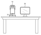
도 1은 본 발명의 일 실시예에 따른 안과용 치료장치를 개략적으로 도시한 도면이다. 본 실시예에 따른 안과용 치료장치는 안저에 치료광을 조사하여 치료를 수행하는 장치로, 도 1에 도시된 바와 같이 슬릿 램프(10) 및 인터페이스부(20)를 포함하여 구성된다.1 is a view schematically showing an ophthalmic treatment apparatus according to an embodiment of the present invention. The ophthalmic treatment device according to the present embodiment is a device for performing treatment by irradiating treatment light to the fundus, and includes a
슬릿 램프(10)는 사용자가 환자의 눈을 관찰하며 치료를 진행하는 장치이다. 슬릿 램프(10)의 본체 일측에는 환자의 눈의 위치를 고정시키기 위한 대안부(object part)(180)가 구비된다. 그리고, 타측에는 환자의 눈을 관찰하기 위해 사용자의 눈이 위치하는 접안부(eyepiece part)(170)가 구비된다. 그리고, 슬릿 램프(10) 내부에는 치료 동작을 수행하기 위한 다양한 구성요소가 구비되며, 이에 대해서는 아래에서 보다 구체적으로 설명한다. 그리고, 슬릿 램프의 외부에는 치료 장치의 동작을 제어하기 위한 조작부(30)가 구비될 수 있다. 조작부(30)는 키보드, 조이스틱, 페달 등의 구조를 이용하여 구성되며, 사용자는 조작부(30)를 조작하여 슬릿 램프의 시야 방향 또는 치료 장치의 치료 동작 등을 조작할 수 있다.The
인터페이스부(20)는 슬릿 램프(10)와 인접한 위치에 구비되어, 치료 중 사용자에게 필요한 각종 정보를 표시하거나, 사용자가 명령 및 정보를 입력/설정하도록 구성된다. 도 1에 도시된 바와 같이, 인터페이스부(20)는 모니터와 같은 디스플레이 장치를 포함하여 구성된다. 그리고, 디스플레이 장치의 터치 스크린 기능을 통해 정보를 입력하도록 구성되거나, 키보드나 마우스와 같은 별도의 입력장치를 구비할 수 있다.The
도 2는 도 1의 안과용 치료장치의 내부 구성요소를 개략적으로 도시한 블록도이다. 슬릿 램프(10)는 치료광을 발생시켜 안저로 치료광을 조사하는 치료광 조사부를 포함한다. 치료광 조사부는 치료광(treatment beam)을 발생시키는 치료광 발생부(110) 및 치료광 발생부에서 발생된 치료광을 안저로 전달하기 위한 빔 딜리버리부(130)를 포함하여 구성된다. 또한, 치료광이 조사되는 위치를 표시하기 위한 조준광 발생부(120)를 더 포함할 수 있다. 나아가, 환자의 안저 이미지를 촬영하기 위한 촬상부(140), 치료광에 의한 조직의 상태 변화 정보를 감지하기 위한 모니터링부(150) 및 각종 구성요소를 제어하기 위한 제어부(160) 등을 더 포함할 수 있다. 2 is a block diagram schematically showing the internal components of the ophthalmic treatment apparatus of FIG. 1. The
치료광 발생부(110)는 치료광 광원(미도시) 및 치료광 광원에서 생성되는 치료광의 특성을 조절하는 각종 광학 소자(미도시)를 포함하여 구성된다. 본 실시예의 치료광 광원은 Nd:YAG, Ho:YAG 등과 같은 레이저 매질 또는 레이저 다이오드를 포함하여 구성되어, 치료광으로서 레이저를 발생시킨다. 치료광의 파장, 펄스폭(pulse width) 및 출력 등의 파라미터는 병변 내용 및 타겟 조직의 특성을 고려하여 결정되거나 조절될 수 있다. The
빔 딜리버리부(130)는 복수의 광학소자로 구성되어, 치료광이 진행하는 광 경로를 형성한다. 따라서, 치료광 발생부(110)에서 발생된 치료광은 빔 딜리버리부(130)를 따라 진행하여 안저 방향으로 조사된다.The
이러한 빔 딜리버리부(130)는 치료광 이외에도 후술할 조준광 및/또는 촬영광이 진행하는 광 경로를 형성할 수 있다. 도 2에 도시된 바와 같이, 빔 딜리버리부(130)는 적어도 하나 이상의 빔 컴바이너(beam combiner)(131)를 구비하여, 조준광 및/또는 촬영광은 광 경로상에 합류되고, 안저 방향으로 조사될 수 있다. 그리고, 안저에서 반사되는 조준광 및/또는 촬영광은 빔 딜리버리부(130)를 통해 역 방향으로 진행하여, 접안부(170)로 진행하거나 촬상부(140)로 수광될 수 있다. 다만, 본 발명이 이에 한정되는 것은 아니며, 조준광 및/또는 촬영광은 치료광의 조사 경로와 구분되는 별도의 광 경로를 형성하거나, 생략하여 실시할 수 있다.In addition to the treatment light, the
빔 딜리버리부(130)는 광이 조사되는 위치를 변경시키는 스캐너(132)를 포함한다. 스캐너(132)는 적어도 하나 이상의 반사부재 및 이를 회전시키는 구동유닛을 포함하여 구성된다. 스캐너(132)는 반사부재를 회전시키면서, 반사부재에 의해 반사되는 광의 조사 위치를 변경시킬 수 있다. 또한, 도 2에 도시되지는 않았으나, 빔 딜리버리부(130)는 광을 집속시키거나 분산시키기 위한 복수의 광학 렌즈, 광학 필터 등의 광학 소자를 더 포함할 수 있다. 빔 딜리버리부(130)는 이러한 광학 소자들을 이용하여 치료광이 치료 영역 상에 조사되는 스팟 사이즈를 비롯하여 다양한 파라미터를 조절할 수 있다.The
빔 딜리버리부(130)의 말단에는 대안부(object part)(180)가 구비된다. 대안부(180)는 치료 대상이 되는 환자의 눈이 위치되는 구성으로, 대물렌즈 또는 환자의 눈과 접촉하는 컨택트 렌즈를 포함하여 구성된다. 나아가, 대안부는 환자의 눈을 고정시킬 수 있도록, 환자의 전안부를 흡입하여 고정시키는 석션 장치를 더 포함할 수 있다.An
한편, 조준광 발생부(120)는 조준광(aiming beam)을 발생시킨다. 조준광은 치료광을 조사하기 이전, 또는 치료광이 조사되는 동안 시술자가 치료광이 조사되는 위치를 확인할 수 있도록, 치료광이 조사되는 치료 위치로 조사되어 해당 위치를 표시하는 구성이다. 조준광 발생부(120)에서 발생된 조준광은 빔 딜리버리부(130)를 통해 안저의 치료 영역으로 조사된 후 반사된다. 이때, 조준광은 가시광 대역의 파장을 갖고, 사용자는 접안부를 통해 이를 확인하여 조준광의 위치를 확인할 수 있다.Meanwhile, the aiming
다만, 치료광이 조사되는 위치를 인터페이스부에 표시된 안저 이미지 상에서 확인이 가능한 경우, 조준광 발생부를 생략하여 실시하는 것도 가능하다.However, if the position to which the treatment light is irradiated can be confirmed on the fundus image displayed on the interface unit, it is possible to omit the aiming light generation unit.
한편, 촬상부(140)는 환자의 치료 영역의 이미지를 획득하는 구성이다. 촬상부(140)는 촬상 소자를 포함하여 구성되며, 촬영 광원(미도시)에서 조사되는 촬영광이 안저로부터 반사되는 것을 수광하여 안저 이미지를 획득한다. 본 실시예에 따른 촬상부(140)는 치료 영역을 전체를 포함하는 안저 이미지를 획득하도록 구성된다. 다만, 이 이외에도 촬영광의 조사 위치가 치료광과 같이 스캐너를 통해 변경되도록 구성되어, 치료광 조사 위치와 인접한 영역의 이미지를 획득하도록 구성하는 것도 가능하다. 또한, 본 실시예에서는 촬상부를 포함하는 안과용 치료장치를 설명하고 있으나, 이에 한정되는 것은 아니며 촬상부에 상응하는 구성을 생략하여 실시하는 것도 가능하다.Meanwhile, the
그리고, 모니터링부(150)는 치료광이 치료 위치로 조사되는 동안 해당 치료 위치에 위치한 조직의 상태 변화 정보를 감지하는 구성으로, 구체적인 구성 및 동작에 대해서는 아래에서 보다 자세히 설명한다.In addition, the
제어부(160)은 치료광 발생부(110), 조준광 발생부(120), 빔 딜리버리부(130), 촬상부(140) 등을 비롯한 각종 구성요소를 제어하는 구성으로, 사용자가 조작부(30)을 통해 조작하는 내용 또는 인터페이스부(20)을 통해 입력되거나 설정되는 내용에 근거하여 각종 구성요소를 제어한다. 또한, 제어부(160)는 촬상부(140)에서 촬상된 이미지 정보 및 모니터링부(150)에서 감지되는 정보 등을 전달받고, 이러한 정보들을 가공 및 연산하여 다른 구성요소로 전달하거나, 이에 근거하여 다른 구성요소의 동작 제어하는 역할을 수행한다.The
한편, 인터페이스부(20)는 표시부(210) 및 입력부(220)를 포함하여 구성된다. 여기서, 표시부(210)는 사용자에게 각종 정보를 표시 전달하기 위한 구성이며, 입력부(220)는 사용자가 정보 및 명령을 전달할 수 있는 구성이다. Meanwhile, the
여기서, 표시부(210)는 이미지를 비롯한 각종 정보를 표시할 수 있는 디스플레이 장치로 구성된다. 전술한 촬상부(140)에서 촬영된 안저 이미지, 또는 별도의 안저 카메라 등에서 앞서 촬영된 안저 이미지는 제어부(160)를 통해 전달되어 표시부(210) 상에 표시되고, 사용자는 표시부(210)를 통해 환자의 안저 이미지를 확인할 수 있다. 이러한 안저 이미지는 치료 전 병변 위치를 확인하거나, 치료광의 조사 위치를 설정하거나, 치료 결과를 확인하는데 다양하게 활용될 수 있다. 그리고, 안저 이미지 이외에도 다양한 정보들이 표시부를 통해 사용자에게 표시될 수 있다.Here, the
입력부(220)는 사용자가 치료 장치로 각종 정보 또는 명령을 전달하는 구성이다. 따라서, 사용자는 입력부(220)를 통해 환자 정보, 치료 정보를 입력하고, 치료 동작을 명령하고, 치료 장치에서 제공하는 다양한 옵션 중 원하는 것을 선택하는 것이 가능하다. 예를 들어, 사용자는 입력부(220)를 이용하여 표시부(210)에 표시된 안저 이미지 상의 치료 영역을 설정하는 것도 가능하며, 치료 장치에서 제안하는 치료 모드 중 어느 하나를 선택하거나, 치료 장치에 저장된 치료광 조사 패턴 중 어느 하나를 선택하는 것도 가능하다. 입력부(220)는 키보드 또는 마우스 등과 같은 별도의 입력 장치를 이용하거나, 표시부(210)를 형성하는 디스플레이의 터치 스크린 기능을 이용하여 각종 정보를 입력하도록 구성하는 것도 가능하다.The
이러한 안과용 치료장치는, 사용자가 입력부(220) 또는 조작부(30)을 통해 치료 위치 및 치료광의 파라미터를 결정하고, 제어부(160)는 이에 근거하여 치료 장치의 치료 동작을 제어한다.In such an ophthalmic treatment device, a user determines a treatment location and parameters of a treatment light through the
도 3은 도 2의 A 영역을 확대하여 그린 단면도이다. 도 3의 A는 치료 영역에 해당하는 환자의 안저 조직, 특히 망막 조직을 도시한 도면이다. 이러한 망막의 조직은 일반적으로 내경계층(internal limiting layer), 신경 섬유층(nerve fiber layer), 신경절세포층(ganglion cell layer), 내망상층(inner plexiform layer), 내과립층(inner nuclear layer), 외망상층(outer plexiform layer), 외과립층(outer nuclear layer), 외경계층(external limiting layer), 광수용 세포층(photo receptor layer), RPE 층(retinal pigment epithelial layer)의 10개의 층으로 이루어진다(망막 표면으로부터 내측 깊이 방향).3 is an enlarged cross-sectional view of area A of FIG. 2. 3A is a diagram showing a patient's fundus tissue, particularly a retinal tissue, corresponding to a treatment area. These tissues of the retina are generally internal limiting layer, nerve fiber layer, ganglion cell layer, inner plexiform layer, inner nuclear layer, and external retina. It consists of 10 layers: the outer plexiform layer, the outer nuclear layer, the external limiting layer, the photo receptor layer, and the RPE layer (retinal pigment epithelial layer). Inward depth direction).
이 중 RPE 세포층은 위의 10개의 층 중 후측 방향의 경계층을 형성하며, 타이트 정션(tight junction)구조로 형성된다. 그리고 RPE 층의 하측으로는 브루크 막(Bruch's membrane)이 위치한다. 이러한 RPE 층은 맥락막(choroid)에 위치하는 혈관 등으로부터 영양분 및 산소를 공급받아 광 수용체(photo receptor)에 영양분을 공급하고, 광 수용체로부터 생성되는 노폐물을 브루크 막을 통해 배출하는 역할을 수행한다.Among them, the RPE cell layer forms a boundary layer in the posterior direction among the above 10 layers, and is formed in a tight junction structure. And Bruch's membrane is located under the RPE layer. The RPE layer receives nutrients and oxygen from blood vessels located in the choroid, supplies nutrients to a photo receptor, and discharges waste products generated from the photoreceptors through the Bruck membrane.
RPE 층을 형성하는 PRE 세포의 일부가 정상적인 기능을 수행하지 못하게 되면, 해당 RPE 세포의 전방에 위치하는 광 수용체들은 정상적으로 영양 및 산소가 공급되지 않아 괴사할 수 있다. 이를 치료하기 위해, 본 실시예에 따른 안과용 치료장치는 RPE 세포층에 선택적으로 치료광을 조사하여 에너지를 전달함으로써, 새로운 RPE 세포의 재생을 유도하는 치료를 진행한다.When some of the PRE cells forming the RPE layer fail to perform their normal functions, the photoreceptors located in front of the RPE cells are not normally supplied with nutrients and oxygen and may die. In order to treat this, the ophthalmic treatment device according to the present embodiment performs a treatment that induces regeneration of new RPE cells by selectively irradiating therapeutic light to the RPE cell layer to deliver energy.
보다 구체적으로 설명하면, 치료광은 가시광선 또는 근적외선 영역의 파장을 갖는다. 이러한 치료광은 망막의 전방에 위치하는 세포층(첫 번째 세포층 내지 아홉 번째 세포층)에는 거의 흡수되지 않고 투과한 후, RPE 세포 내부에 존재하는 멜라노좀에 흡수된다. 멜라노좀에 흡수되는 에너지의 양이 증가함에 따라 RPE 세포는 온도가 상승하면서 상태가 변화하고, 이에 의해 상태가 변화된 RPE 세포는 건강한 RPE 세포로 대체된다. 이는 온도가 상승함에 따라 멜라노좀의 표면에서 미세기포(microbubble)이 발생하여 점차적으로 성장하고, 이에 의해 해당 RPE 세포가 선택적으로 괴사되어 새로운 RPE 세포가 유도되는 것으로 예상하고 있다.More specifically, the treatment light has a wavelength in the visible or near-infrared region. Such therapeutic light is hardly absorbed by the cell layer (first cell layer to ninth cell layer) located in front of the retina, but is transmitted through it, and is then absorbed by the melanosomes present inside the RPE cells. As the amount of energy absorbed by the melanosomes increases, the RPE cells change their state as the temperature rises, and the RPE cells whose state has changed are replaced by healthy RPE cells. It is expected that as the temperature rises, microbubbles are generated on the surface of melanosomes and gradually grow, thereby selectively necrosis of the corresponding RPE cells, leading to new RPE cells.
다만, 치료광에 의해 RPE 세포에 지나치게 많은 양의 에너지가 전달되면, 타겟 조직에 해당하는 RPE 세포 뿐 아니라 인접한 광 수용체까지 손상되어 시력 손상을 야기할 수 있다. 반면, 치료광에 의해 RPE 세포에 전달되는 에너지가 충분하지 않은 경우, RPE 세포의 상태가 변화하지 않으면서 치료가 이루어지지 않을 수 있다. 따라서, 본 실시예에 따른 안과용 치료장치는 모니터링부(150)를 구비하여, 치료가 진행되는 동안 치료 위치에 위치한 조직, 보다 구체적으로는 타겟 조직의 상태 변화를 실시간으로 모니터링하면서 치료 내용을 조절하는 것이 가능하다.However, if an excessive amount of energy is transmitted to the RPE cells by the therapeutic light, not only the RPE cells corresponding to the target tissue but also adjacent photoreceptors may be damaged, resulting in visual damage. On the other hand, when the energy delivered to the RPE cells by the treatment light is not sufficient, treatment may not be performed without changing the state of the RPE cells. Therefore, the ophthalmic treatment device according to the present embodiment includes a
본 실시예에 따른 모니터링부(150)는 치료 위치로 모니터링 광을 조사하고, 광 티텍터(photo detector)와 같은 검출 유닛(155)을 이용하여 치료 위치에서 반사되는 모니터링 광을 수광한다. 이에 의해, 검출 유닛에서 검출되는 신호를 이용하여 타겟 조직의 상태 변화 정보를 모니터링한다. 조직의 상태가 동일한 경우에는 반사되는 모니터링 광의 특성이 일정한 상태를 유지하는 것에 비해, 조직의 상태 변화가 발생하는 경우 미세 기포 등에 의해 광의 산란이 일어나면서 반사되는 모니터링 광의 특성이 변화하는 현상을 이용하는 것이다.The
이러한 검출 유닛(155)은 광이 수광되면 이에 의해 전기적 신호를 생성한다. 생성되는 신호의 크기는 광의 강도(intensity)와 상관 관계를 갖는다. 다만, 반사되는 모니터링 광의 강도 중 조직의 상태 변화에 기인한 광의 강도 변화는 상대적으로 미세하기 때문에, 검출 유닛에서 검출되는 신호 자체만으로 조직의 상태 변화를 인식하는 것이 쉽지 않고, 노이즈 등을 오인하여 부정확한 판단을 할 우려가 있다. 따라서, 본 실시예에 따른 모니터링부(150)는 적어도 두 개의 검출 유닛(155a, 155b)을 포함하고, 각 검출 유닛(155a, 155b)이 각각 반사되는 모니터링광을 수광하여 발생하는 신호를 이용하여 조직의 상태 변화를 모니터링할 수 있다.When light is received, the
도 4는 조직의 상태 변화 전 상태를 모사한 샘플에 대해 모니터링을 수행한 결과이고, 도 5는 조직의 상태 변화가 이루어진 상태를 모사한 샘플에 대해 모니터링을 수행한 결과를 도시한 것이다. 이하에서는, 도 4 및 도 5를 참조하여, 본 실시예에 따른 모니터링부에 적용되는 기술 사항을 설명한다.FIG. 4 is a result of monitoring a sample that simulates a state before a change in the state of a tissue, and FIG. 5 shows a result of monitoring a sample that simulates a state in which the state of a tissue is changed. Hereinafter, technical matters applied to the monitoring unit according to the present embodiment will be described with reference to FIGS. 4 and 5.
도 4 및 도 5에 도시된 바와 같이, 하나의 샘플 위치에서 반사되는 광은 각각의 검출 유닛(155a, 155b)으로 수광된다. 이때, 반사되는 광은 광의 단면을 기준으로 절반으로 분할되어 각각의 검출 유닛으로 수광된다.4 and 5, the light reflected from one sample position is received by each
이때, 도 4와 같이 조직의 상태 변화가 발생하지 않은 상태에서는, 반사체인 샘플이 동일한 특성을 유지하므로 각각의 검출 유닛에서 검출되는 신호는 DC 신호와 같이 (노이즈 등에 의한 미세한 변화를 포함하나) 실질적으로 일정한 신호값을 유지한다. 또한, 반사되는 광을 단면 기준으로 정확하게 2개로 분할하는 경우, 반사되는 광의 단면은 대칭적인 파면을 형성하므로, 각 검출 유닛(155a, 155b)이 서로 상이한 단면 영역을 통과하는 광을 수광하더라도, 각 검출 유닛에서 획득하는 신호는 실질적으로 동일한 형태를 유지할 수 있다.At this time, as shown in FIG. 4, in a state in which no change in the state of the tissue has occurred, since the sample as the reflector maintains the same characteristics, the signal detected by each detection unit is substantially the same as the DC signal (including minute changes due to noise, etc.) To maintain a constant signal value. In addition, when the reflected light is accurately divided into two based on the cross-section, the cross-section of the reflected light forms a symmetrical wavefront, so even if the
반면, 도 5와 같이 조직의 상태 변화가 발생하여 조직 특성이 변화하거나 미세 기포 등에 의해 산란이 발생하게 되면, 각각의 검출 유닛에서 검출되는 신호는 지터(jitter)가 발생하면서, 미약한 AC 신호를 포함하는 변동(fluctuation)을 나타낸다. 특히, 조직의 상태 변화에 따라 기포가 발생하는 등의 이유로 광의 산란이 발생하게 되면, 반사되는 광의 파면(wavefront) 특성이 랜덤하게 변화하여, 각 검출 유닛(155a, 155b)에서 검출되는 신호는 비대칭 특성을 갖는다.On the other hand, when a change in the state of the tissue occurs as shown in FIG. 5 and the tissue characteristics change or scattering occurs due to microbubbles, the signal detected by each detection unit generates jitter and generates a weak AC signal. It represents the fluctuation to be included. In particular, when light scattering occurs due to the occurrence of bubbles due to changes in the state of the tissue, the wavefront characteristics of the reflected light are randomly changed, and the signals detected by each
이때, 두 검출 유닛(155a, 155b)에서 검출되는 신호의 차이를 관찰할 경우, 도 4와 같이 조직 상태 변화가 발생하지 않은 상태에서는 실질적으로 일정하고 대칭적인 신호값을 갖기 때문에 두 신호의 차이는 상대적으로 작고 일정한 값을 나타난다. 반면, 도 5와 같이 조직의 상태 변화가 발생한 상태에서는 각 신호값이 랜덤하고 비대칭적인 변동(fluctuation)을 나타내기 때문에, 두 신호의 차이는 상대적으로 크고 변동성이 큰 값을 나타낸다. 따라서, 이에 의할 경우 조직의 상태 변화를 용이하게 식별하는 것이 가능하며, 본 실시예에 따른 모니터링부는 이러한 원리를 이용하여 조직의 상태 변화를 모니터링하도록 구성할 수 있다.At this time, when observing the difference between the signals detected by the two
도 6은 도 2의 모니터링부를 포함한 주요 광학계를 개략적으로 도시한 도면이다. 도 6에서는 설명의 편의상 치료광 발생부(110), 빔 딜리버리부(130) 및 모니터링부(150)를 중심으로 일부 구성 요소를 생략하여 단순하게 도시한 것으로, 본 발명의 구성이 이에 한정되는 것은 아니다. 6 is a diagram schematically illustrating a main optical system including the monitoring unit of FIG. 2. In FIG. 6, for convenience of explanation, some components are omitted and simplified around the
도 6에 도시된 바와 같이, 본 실시예에 따른 모니터링부(150)는 모니터링 광원(151), 광 분할기(152), 적어도 2개의 검출 유닛(155a, 155b) 및 프로세서(156)를 포함하여 구성된다. 이때, 광 분할기(152)는 반사되는 모니터링 광을 검출 유닛(155)의 개수에 상응하는 수로 분할하고, 각 검출 유닛(155a, 155b)은 분할된 광을 수광하여 신호를 검출하도록 구성된다. 검출 유닛(155)의 개수는 다양하게 구성할 수 있으나, 도 6에 도시된 것과 같이, 본 실시예에서는 일 예로서 2개의 검출 유닛을 이용하여 구성한다.As shown in FIG. 6, the
모니터링 광원(151)은 치료광이 치료 위치로 조사되는 동안 치료 위치로 조사되는 모니터링 광을 생성한다. 모니터링 광원(151)에서 생성된 모니터링 광은 빔 딜리버리부(130)를 통해 치료 위치로 조사되며, 치료 위치에서 반사되어 빔 딜리버리부(130)를 통해 모니터링부의 검출 유닛(155) 측으로 전달된다. 이때 모니터링 광은 치료 위치의 표면 뿐 아니라 치료 위치의 내측에 위치한 타겟 조직까지 도달할 수 있는 파장의 광일 수 있으며, 일 예로서 830nm의 파장의 광을 이용할 수 있다. 따라서, 치료 위치에서 반사되는 모니터링 광은 치료 위치의 표면 조직 뿐 아니라 내측에 위치한 타겟 조직의 상태 정보까지 포함할 수 있다.The monitoring
반사되는 모니터링 광이 진행하는 광 경로 상에는 광 분할기(152)가 배치된다. 광 분할기(152)는, 반사된 모니터링 광이 각각의 검출 유닛에 수광되도록, 반사된 모니터링 광을 분할한다. 이때, 광 분할기(152)는 반사되는 모니터링 광을 광의 단면 영역을 기준으로 적어도 두 개의 광으로 분할하며, 구체적으로, 광의 단면 영역을 기준으로 각각 절반으로 구분하여 두 개의 광으로 분할하도록 구성한다. 일 예로, 광 분할기는 직각 프리즘 거울로 구성되며, 직각 프리즘 거울의 반사면 경계가 광의 단면 중심을 가로지르도록 배치될 수 있다.The
그리고, 검출 유닛(155)은 반사된 모니터링 광을 수광하여 이를 전기적 신호로 변환하는 구성으로, 포토 디텍터(photo detector)로 구성된다. 도 6에 도시된 바와 같이, 본 실시예의 검출 유닛(155)은 2개의 검출 유닛(155a, 155b)을 포함하며, 각 검출 유닛(155a, 155b)은 광 분할기에 의해 분할된 광을 수광할 수 있도록 배치된다. 구체적으로, 반사되는 모니터링 광이 광 분할기에 의해 광의 단면 기준으로 절반으로 분할되면, 상기 단면 중 제1 절반 영역을 통과하는 광은 제1 검출 유닛(155a)으로 수광되고, 제2 절반 영역을 통과하는 광은 제2 검출 유닛(155b)으로 수광된다. 광 분할기(152)와 각 검출 유닛(155a, 155b) 사이에는 집광 소자(153) 및 광 파이버(154)가 배치되어, 분할된 광은 집광 소자에 의해 집속된 상태로 각 검출 유닛(155)에 수광되며, 검출 유닛(155)은 수광되는 광의 강도(intensity)에 따라 전기적 신호를 생성한다.In addition, the
모니터링부의 프로세서(156)는 각 검출 유닛(155a, 155b)에서 생성된 전기적 신호를 전달받고, 이에 근거하여 조직의 상태 변화를 판단하는 구성이다. 프로세서(156)는 전술한 바와 같이, 각 검출 유닛(155a, 155b)에서 검출된 신호 중 비대칭적인 신호를 추출하여 조직의 상태 변화 정보를 모니터링하며, 일 예로서 각 검출 유닛에서 검출되는 신호값의 차이를 이용할 수 있다.The
구체적으로, 프로세서(156)는 치료가 진행되는 동안 제1 검출 유닛(155a)에서 실시간으로 검출되는 제1 신호(A) 및 제2 검출 유닛(155b)에서 실시간으로 검출되는 제2 신호(B)을 전달받고, 이를 이용하여 기 설정된 연산식을 통해 모니터링 신호(S)를 획득할 수 있다. 이때, 기 설정된 연산식은 각 신호값의 차이에 해당하는 값이 반영되도록 설정되며, 본 실시예에서는 하기 연산식을 이용하여 모니터링 신호를 획득한다.Specifically, the
[식] ![]()
![]()
상기 연산식은 각 신호값의 차이에 해당하는 값을 정규화하도록 설정된 식으로, 이 이외에도 다양한 연산식을 이용하여 모니터링 신호를 획득할 수 있다.The equation is set to normalize a value corresponding to the difference between each signal value, and a monitoring signal may be obtained using various equations.
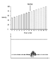
도 7은 도 6의 모니터링부에서 치료가 진행되는 동안 획득되는 신호를 도시한 그래프이다. 도 7에 도시된 바와 같이, 제1 검출 유닛(155a) 및 제2 검출 유닛(155b)에서 검출되는 신호는 치료 초기 일정한 신호값을 유지하고, 조직의 상태 변화가 발생하는 시점에서 신호값에 변동이 발생한다. 다만, 이러한 변동의 폭이 미세하여 식별이 용이하지 않은 것에 비해, 제1 신호 및 제2 신호를 연산하여 획득되는 모니터링 신호는 조직 상태 변화 시점에서 변동의 폭이 크게 발생하는 것을 확인할 수 있다. 7 is a graph showing signals acquired while treatment is in progress by the monitoring unit of FIG. 6. As shown in Fig. 7, the signals detected by the
따라서, 프로세서(156)는 모니터링 신호와 기 설정된 기준값을 비교하여 조직의 상태 변화 여부를 판단한다. 이때, 기준값은 모니터링 신호의 변동 폭에 대응되는 값으로 설정될 수 있으며, 모니터링 신호의 변동 폭이 기준값보다 작은 경우 조직의 상태 변화가 발생하지 않은 것으로 판단하고, 변동 폭이 기준값 이상이면 조직에 목표한 상태 변화가 발생한 것으로 판단할 수 있다. 다만, 본 실시예의 프로세서는 기준값을 모니터링 신호의 변동폭에 대응되는 값으로 설정하였으나, 이 이외에도 치료 부위, 병변 또는 모니터링 신호를 도출하는 연산식 등에 따라 다양한 방식으로 기준값을 설정할 수 있음은 물론이다.Accordingly, the
이처럼, 본 실시예에 따른 모니터링부(150)는 적어도 두 개의 검출 유닛(155a, 155b)에서 획득되는 신호가 조직의 상태 변화 중 비대칭성을 갖는 점을 이용하여, 이를 극대화하는 방식으로 모니터링 신호를 생성하는 바, 이를 이용하여 치료 중 조직의 상태 변화를 정확하게 모니터링할 수 있다. As such, the
다만, 본 실시예에 따른 모니터링부는 별도의 모니터링 광을 조사하는 모니터링 광원을 구비하고, 적어도 2개의 검출 유닛은 반사되는 모니터링 광을 수광하여 조직의 상태 변화 정보를 감지하는 구성으로 설명하였으나, 본 발명이 이에 한정되는 것은 아니다. 다른 실시예로서, 모니터링부는 별도의 모니터링 광원을 구비하지 않고, 반사되는 치료광을 이용하여 조직의 상태 변화 정보를 감지하도록 구성하는 것도 가능하다. 구체적으로, 치료 중 치료 위치로 조사된 치료광은 치료 위치에서 반사되어 장치 내측의 빔 딜리버리부 진입하고, 반사된 치료광은 광 분할기에 의해 분할되어 각각의 검출 유닛으로 수광되도록 구성될 수 있다. 그리고, 각 검출 유닛은 반사된 치료광이 수광됨에 따라 신호가 검출되고, 프로세서는 각 검출된 신호에 근거하여 조직의 상태 변화 정보를 판단하도록 구성하는 것도 가능하다. 치료광을 이용하여 모니터링을 수행하는 경우에도, 기본적인 구성 및 기술적 원리는 도 6에서 설명한 내용과 실질적으로 동일하거나 유사하므로 구체적인 설명은 생략한다.However, the monitoring unit according to the present embodiment has been described as having a monitoring light source that irradiates separate monitoring light, and at least two detection units receive the reflected monitoring light to detect tissue state change information. This is not limited to this. As another embodiment, the monitoring unit may not include a separate monitoring light source, and may be configured to detect tissue state change information using reflected treatment light. Specifically, the treatment light irradiated to the treatment position during treatment may be reflected at the treatment position to enter the beam delivery unit inside the device, and the reflected treatment light may be divided by a light splitter to be received by each detection unit. In addition, each detection unit may be configured to detect a signal as the reflected treatment light is received, and the processor to determine tissue state change information based on each detected signal. Even when monitoring is performed using the treatment light, the basic configuration and the technical principle are substantially the same as or similar to those described in FIG. 6, and thus a detailed description thereof will be omitted.
도 8은 모니터링 정보에 근거하여 제어부(160)가 치료광 조사를 제어하는 내용을 도시한 그래프이다. 전술한 바와 같이, 제어부(160)는 치료광 조사부를 비롯한 각종 구성요소를 제어하며, 치료 중 모니터링부(150)에서 모니터링되는 조직의 상태 변화 정보에 근거하여 치료 내용을 제어할 수 있다.8 is a graph showing contents of the
구체적으로, 도 8에 도시된 바와 같이, 하나의 치료 위치의 조직을 치료함에 있어, 치료광 조사부는 해당 치료 위치에 순차적으로 강도가 증가하는 복수의 치료광 펄스를 조사하도록 제어될 수 있다. 이때, 치료광이 조사되는 동안 모니터링부(150)는 해당 치료 위치로 모니터링 광을 조사하고, 적어도 두 개의 검출 유닛(155a, 155b)에서 검출되는 신호를 이용하여 모니터링 신호를 생성하고, 이에 근거하여 조직의 상태 변화 정보를 모니터링할 수 있다. 제어부(160)는, 모니터링을 통해 해당 치료 위치의 조직에서 목표한 상태 변화가 발생한 것으로 판단되면, 해당 치료 위치에 추가적으로 치료광을 조사하는 것을 중단하고 치료를 종료하도록 제어될 수 있다. 따라서, 해당 치료 위치에 충분한 치료를 진행하면서도 과도한 에너지 전달로 인해 인접 조직이 손상되는 것을 방지할 수 있다.Specifically, as shown in FIG. 8, in treating a tissue at one treatment location, the treatment light irradiation unit may be controlled to irradiate a plurality of treatment light pulses sequentially increasing in intensity to the treatment location. At this time, while the treatment light is irradiated, the
다만, 도 8에 도시된 제어 내용은 일 예에 불과하며, 제어부는 모니터링 정보에 근거하여 다양한 방식으로 치료광 조사를 제어할 수 있음은 물론이다.However, the control content illustrated in FIG. 8 is only an example, and it goes without saying that the controller may control the treatment light irradiation in various ways based on the monitoring information.
또한, 도 6에서는 프로세서가 모니터링부의 하위 구성요소로 구성되어 모니터링 신호를 생성하고 조직의 상태 변화를 판단하는 것으로 설명하였으나, 본 발명이 이에 한정되는 것은 아니며 프로세서가 제어부의 하위 구성으로 구성되어 각 검출 유닛에서 검출되는 신호를 이용하여 제어부가 조직의 상태 변화를 판단하도록 구성하는 것도 가능하다.In addition, in FIG. 6, it has been described that the processor is composed of sub-elements of the monitoring unit to generate a monitoring signal and determine the change in the state of the organization, but the present invention is not limited thereto, and the processor is configured as a sub-element of the control unit to detect each It is also possible to configure the control unit to determine the change in the state of the tissue using the signal detected by the unit.
이하에서는 도 9 내지 11을 참조하여, 본 실시예에 따른 안과용 치료장치의 제어방법을 구체적으로 설명한다.Hereinafter, a control method of the ophthalmic treatment apparatus according to the present embodiment will be described in detail with reference to FIGS. 9 to 11.
도 9는 본 실시예에 따른 안과용 치료장치의 제어방법을 도시한 순서도이다. 도 9에 도시된 바와 같이, 사용자는 우선 환자의 병변을 진단한 후 안저의 치료 영역 및 치료 내용을 결정한다(S100). 그리고, 치료 영역 중 치료광을 조사하여 치료를 진행할 복수의 치료 위치를 결정한다(S200). 이러한 치료 영역 및 치료 내용을 결정하는 단계, 그리고 치료 위치를 결정하는 단계는 전술한 인터페이스(20)를 통해 결정될 수 있다. 그리고, 치료 위치의 개수 및 간격은 환자의 병변 상태 및 치료광의 조사 강도 등에 따라 결정될 수 있다. 9 is a flow chart showing a control method of the ophthalmic treatment device according to the present embodiment. As shown in FIG. 9, the user first diagnoses the lesion of the patient and then determines the treatment area and treatment contents of the fundus (S100). Then, a plurality of treatment positions to be treated are determined by irradiating treatment light in the treatment area (S200). The step of determining the treatment area and treatment content, and the step of determining the treatment location may be determined through the
이에 의해, 복수의 치료 위치가 결정되면, 제1 위치에 대한 치료를 진행한다(S300). 그리고, 제1 위치에 대한 치료가 종료되면, 제2 위치로 치료 위치를 변경하여 제1 위치와 동일한 방식으로 치료를 진행한다(S400). 그리고, 나머지 치료 위치 또한 동일한 방식으로 순차적으로 치료를 진행할 수 있다.Accordingly, when a plurality of treatment positions are determined, treatment for the first position is performed (S300). Then, when the treatment for the first position is finished, the treatment position is changed to the second position and the treatment is performed in the same manner as the first position (S400). In addition, the remaining treatment locations may also be sequentially treated in the same manner.
도 10은 도 9의 제1 위치를 치료하는 단계의 순서를 도시한 순서도이다. 제1 위치를 치료하는 단계는 치료광이 조사되는 위치를 제1 위치로 정렬시키고, 치료광 조사부를 제어하여 치료광을 조사하는 단계를 수행한다(S310). 이때, 제어부(160)는 빔 딜리버리부(130)를 제어하여 치료광이 조사되는 위치를 결정하고, 치료광 발생부(110)를 제어하여 조사되는 치료광의 패턴 및 파라미터를 조절한다.FIG. 10 is a flow chart illustrating a procedure of treating the first position of FIG. 9. In the step of treating the first position, the position to which the treatment light is irradiated is aligned to the first position, and the treatment light is irradiated by controlling the treatment light irradiation unit (S310). In this case, the
치료광은 전술한 바와 같이, 제1 위치의 타겟 조직인 RPE 세포층에 선택적으로 에너지를 전달할 수 있는 파장을 갖는 레이저로 구성된다. 그리고, 최소의 에너지로 타겟 조직의 목표한 상태 변화를 야기할 수 있도록, 제1 위치로 복수의 치료광 펄스를 순차적으로 조사되며, 순차적으로 조사되는 복수의 치료광 펄스는 출력이 순차적으로 증가하는 형태로 조사될 수 있다.As described above, the treatment light is composed of a laser having a wavelength capable of selectively transferring energy to the RPE cell layer, which is a target tissue at the first location. In addition, a plurality of treatment light pulses are sequentially irradiated to the first position to cause a target state change of the target tissue with minimum energy, and the output of the plurality of treatment light pulses sequentially irradiated is sequentially increased. It can be investigated in form.
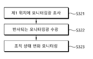
한편, 치료광이 조사되는 동안 모니터링부(150)는 치료광에 의해 제1 위치의 조직이 상태 변화 정보를 모니터링하는 단계를 수행한다(S320). 도 11은 도 10의 모니터링 단계의 내용을 보다 구체적으로 도시한 도면이다.Meanwhile, while the treatment light is irradiated, the
제1 위치에 위치한 조직의 상태 정보를 모니터링하기 위해, 모니터링부(150)는 우선 제1 위치로 모니터링 광을 조사한다(S321). 모니터링 광원에서 조사되는 모니터링 광은 치료광 펄스가 조사되는 주기와 동일한 주기로 조사될 수 있으며, 또는 치료광 펄스가 조사되는 주기보다 짧은 주기로 조사되는 것도 가능하다. In order to monitor the state information of the tissue located at the first location, the
제1 위치로 조사되는 모니터링 광은 제1 위치의 조직 내측까지 전달된 후, 다시 반사되어 안과용 치료장치의 검출 유닛에 수광된다(S322). 이때, 반사되는 모니터링 광이 진행하는 경로상에는 광 분할기가 배치되며, 반사되는 모니터링 광은 광 분할기(152)에 의해 공간적으로 동일한 두 개의 광으로 분할되어 각각 제1 검출 유닛(155a) 및 제2 검출 유닛(155b)에 수광된다. 이때, 광 분할기는 전술한 바와 같이 반사되는 모니터링 광의 단면을 기준으로 각각 절반의 단면 영역을 통과하는 2개의 광으로 분할한다. The monitoring light irradiated to the first position is transmitted to the inside of the tissue at the first position, and then reflected again and received by the detection unit of the ophthalmic treatment device (S322). At this time, a light splitter is disposed on the path of the reflected monitoring light, and the reflected monitoring light is divided into two spatially identical lights by the
분할된 두 개의 광이 각각의 검출 유닛(155a, 155b)으로 수광되면, 각 검출 유닛(155a, 155b)은 수광된 광에 상응하는 전기적 신호를 생성한다. 그리고, 모니터링부(150)는 각 검출 유닛에서 생성된 전기적 신호를 이용하여 제1 위치에 위치한 조직의 상태 정보를 모니터링한다(S323). 이때, 조직의 상태 정보는 전술한 바와 같이, 조직의 상태 변화 발생시 각 검출 유닛에서 검출되는 신호의 비대칭성을 이용할 수 있다 .따라서, 모니터링부는 각 검출 유닛에서 검출되는 신호의 차이에 기초하여 모니터링을 수행한다.When the divided two light is received by each of the
구체적으로, 모니터링부(150)의 프로세서(156)는 제1 검출 유닛(155a)에서 검출된 제1 신호값 및 제2 검출 유닛(155b)에서 검출된 제2 신호값을 이용하여, 기 설정된 연산식에 의해 모니터링 신호(S)를 생성한다. 이때, 생성되는 모니터링 신호는 제1 신호와 제2 신호의 차이값을 정규화하는 형태로 구성되며, 구체적인 연산식은 앞서 설명한 식을 이용할 수 있다. 이로부터 획득되는 모니터링 신호는 조직의 상태 변화가 없는 상태에서는 신호의 변동(fluctuation)이 매우 낮으나, 조직의 상태가 변화하게 됨에 따라 신호의 변동(fluctuation)이 급격하게 증가한다. 따라서, 제1 위치로 치료가 진행되는 동안 실시간으로 모니터링을 수행하면서, 모니터링 신호가 기 설정된 기준값을 초과하는지 여부를 비교하여 제1 위치의 조직이 목표한 상태 변화가 발생하였는지 여부를 모니터링할 수 있다.Specifically, the
다시, 도 10을 기준으로 설명하면, 모니터링 단계를 통해 조직의 상태 변화를 모니터링하고, 제어부(160)는 모니터링된 조직의 상태 정보에 근거하여 치료광의 조사 내용을 제어한다. 예를 들어, 치료 중 모니터링이 이루어지면서 조직의 상태 변화가 발생하지 않은 것으로 발생하면, 제어부(160)는 치료광 펄스의 강도를 증가하여 제1 위치에 치료광 펄스를 조사한다. 반면, 제1 위치의 조직에서 목표한 상태 변화가 발생한 것으로 모니터링 되면, 제어부(160)는 치료광 조사부를 제어하여 제1 위치에 치료광 펄스를 조사하는 것을 중단하고, 제1 위치의 치료를 종료한다(S330).Again, referring to FIG. 10, changes in the state of the tissue are monitored through the monitoring step, and the
전술한 단계를 통해, 제1 위치를 치료하는 단계가 완료되면, 제어부(160)는 치료광의 조사 위치를 제2 위치로 변경하여, 제1 위치의 치료 단계와 동일한 방식으로 제2 위치를 치료한 후, 나머지 치료 위치에 대한 치료를 수행한다.When the step of treating the first position is completed through the above-described steps, the
다만, 도 10 및 도 11에서는 각각의 단계가 순차적으로 도시되어 있으나, 이는 설명의 편의를 위해 이와 같이 도시한 것이며, 일부 단계(예를 들어, 치료광 조사 단계 및 모니터링 단계)는 서로 다른 구성 요소에 의해 동시에 또는 병렬적으로 진행될 수 있다.However, in FIGS. 10 and 11, each step is sequentially illustrated, but this is illustrated as such for convenience of description, and some steps (eg, a treatment light irradiation step and a monitoring step) are different components. It can be done simultaneously or in parallel by
이상에서는, 조직의 상태 변화시 발생되는 신호의 비대칭성을 이용하여, 적어도 두 개의 검출 유닛을 이용하여 조직의 상태 변화를 모니터링하는 안과용 치료장치 및 치료 방법에 대해 설명하였다. 이에 의할 경우, 치료 중 조직의 상태 변화를 실시간으로 모니터링함에 있어, 조직의 상태 변화 발생 전후의 모니터링 신호의 차이가 극명하게 드러나므로, 조직의 상태 변화 시점을 정확하게 파악할 수 있다. 따라서, 해당 치료 위치의 최적 치료가 가능하며, 과도한 치료광 조사로 인해 인접 조직이 손상되는 것을 방지할 수 있다.In the above, an ophthalmic treatment apparatus and a treatment method for monitoring a change in a state of a tissue using at least two detection units have been described using asymmetry of a signal generated when a state of the tissue is changed. In this case, in monitoring the change in the state of the tissue during treatment in real time, the difference in the monitoring signal before and after the occurrence of the change in the state of the tissue is clearly revealed, so that the timing of the change in the state of the tissue can be accurately identified. Accordingly, it is possible to optimally treat a corresponding treatment location, and prevent damage to adjacent tissues due to excessive irradiation of the treatment light.
다만, 전술한 실시예에서는 안저 병변을 치료하는 치료 장치를 중심으로 설명하였으나, 본 발명은 녹내장 치료, 피부 치료 등 안저 이외의 병변을 치료하는 치료장치에도 적용될 수 있다. 이 경우, 전술한 실시예에서 설명한 장치를 중심으로 실시하되, 병변에 따라 조직의 상태 변화 정보를 감지하기 위한 모니터링 신호 생성 방식 및 기준값은 변경하여 적용함으로써 용이하게 실시할 수 있다.However, in the above-described embodiment, a treatment device for treating a fundus lesion has been mainly described, but the present invention can also be applied to a treatment device for treating lesions other than the fundus such as glaucoma treatment and skin treatment. In this case, it is carried out around the apparatus described in the above-described embodiment, but it can be easily implemented by changing and applying the monitoring signal generation method and the reference value for detecting tissue state change information according to the lesion.
이상, 본 발명의 일 실시예에 대해 상세하게 기술하였으나, 본 발명이 상기 실시예에 한정되는 것은 아니다. 본 발명이 속하는 기술 분야에 대해 통상의 지식을 가진 사람이면, 첨부된 청구범위에 정의된 본 발명의 기술적 특징의 범위를 벗어나지 않으면서 본 발명을 여러 가지로 변형 또는 변경하여 실시할 수 있음은 밝혀둔다.In the above, although one embodiment of the present invention has been described in detail, the present invention is not limited to the above embodiment. It has been found that those of ordinary skill in the technical field to which the present invention belongs can perform various modifications or changes to the present invention without departing from the scope of the technical features of the present invention defined in the appended claims. Put.
Claims (21)
적어도 두 개의 검출 유닛을 포함하고, 상기 치료광이 조사되는 동안 상기 적어도 두 개의 검출 유닛에서 검출된 신호를 이용하여 상기 치료 위치에 위치한 조직의 상태 변화 정보를 모니터링하는 모니터링부; 및
상기 모니터링부에서 모니터링된 정보에 근거하여, 상기 치료광 조사부를 제어하는 제어부를 포함하는 안과용 치료장치.A treatment light irradiation unit that irradiates the treatment light to a treatment location located in the eye tissue;
A monitoring unit including at least two detection units, and monitoring state change information of a tissue located at the treatment location by using signals detected by the at least two detection units while the treatment light is irradiated; And
Ophthalmic treatment apparatus comprising a control unit for controlling the treatment light irradiation unit based on the information monitored by the monitoring unit.
상기 모니터링부는 상기 치료광이 조사되는 동안 상기 치료 위치로 조사되는 모니터링 광을 발생시키는 모니터링 광원을 더 포함하고,
상기 적어도 두 개의 검출 유닛은 상기 치료 위치에서 반사된 상기 모니터링 광을 수광하는 것을 특징으로 하는 안과용 치료장치.The method of claim 1,
The monitoring unit further comprises a monitoring light source for generating monitoring light irradiated to the treatment location while the treatment light is irradiated,
The at least two detection units receive the monitoring light reflected from the treatment position.
상기 반사된 모니터링 광이 진행하는 경로 상에 배치되어 상기 반사되는 모니터링 광을 적어도 두 개로 분할하는 광 분할기를 더 포함하고,
상기 적어도 두 개의 검출 유닛은 상기 광 분할기에서 분할된 광을 각각 수광하는 것을 특징으로 하는 안과용 치료장치.The method of claim 2,
Further comprising a light splitter disposed on the path through which the reflected monitoring light travels to divide the reflected monitoring light into at least two,
The at least two detection units respectively receive the light divided by the light splitter.
상기 광 분할기는 상기 반사되는 모니터링 광을 단면 영역을 기준으로 적어도 두 개 이상으로 분할하는 것을 특징으로 하는 안과용 치료장치.The method of claim 3,
The optical splitter divides the reflected monitoring light into at least two or more based on a cross-sectional area.
상기 광 분할기는 상기 반사되는 모니터링 광을 단면 영역을 기준으로 각각 절반의 단면 영역을 갖는 두 개의 광으로 분할하는 것을 특징으로 하는 안과용 치료장치.The method of claim 4,
The optical splitter divides the reflected monitoring light into two lights each having half a cross-sectional area based on a cross-sectional area.
상기 광 분할기는 직각 프리즘 거울로 구성되는 것을 특징으로 하는 안과용 치료장치.The method of claim 3,
The optical splitter is an ophthalmic treatment device, characterized in that consisting of a right angle prism mirror.
상기 광 분할기와 상기 적어도 두 개의 검출 유닛 사이에는 집광 소자 및 광 파이버가 배치되어, 상기 분할된 광을 집광하여 상기 각각의 검출 유닛에 전달하는 것을 특징으로 하는 안과용 치료장치.The method of claim 3,
A condensing element and an optical fiber are disposed between the optical splitter and the at least two detection units, and condensing the divided light and transmitting the collected light to each of the detection units.
상기 모니터링부는 상기 적어도 두 개의 검출 유닛에서 검출되는 신호 중 비대칭적인 신호를 추출하여 상기 조직의 상태 변화 정보를 모니터링하는 것을 특징으로 하는 안과용 치료장치.The method of claim 2,
The monitoring unit extracts an asymmetric signal from among the signals detected by the at least two detection units and monitors information on changes in the state of the tissue.
상기 모니터링부는 상기 적어도 두 개의 검출 유닛에서 검출되는 신호값의 차이를 이용하여 상기 조직의 상태 변화 정보를 모니터링하는 것을 특징으로 하는 안과용 치료장치.The method of claim 2,
The monitoring unit monitors the state change information of the tissue by using a difference between the signal values detected by the at least two detection units.
상기 적어도 두 개의 검출 유닛는 제1 검출 유닛 및 제2 검출 유닛으로 구성되며, 상기 모니터링부는 상기 제1 검출 유닛에서 검출되는 제1 신호값 및 상기 제2 검출 유닛에서 검출되는 제2 신호값을 이용하여 기 설정된 연산식을 통해 연산된 모니터링 신호값에 근거하여 상기 조직의 상태 변화 정보를 모니터링하는 안과용 치료장치.The method of claim 2,
The at least two detection units are composed of a first detection unit and a second detection unit, and the monitoring unit uses a first signal value detected by the first detection unit and a second signal value detected by the second detection unit. Ophthalmic treatment device for monitoring the state change information of the tissue based on a monitoring signal value calculated through a preset formula.
상기 모니터링부는 상기 연산된 모니터링 신호값과 기 설정된 기준값을 비교하여 상기 조직의 상태 변화 정보를 모니터링하는 것을 특징으로 하는 안과용 치료장치.The method of claim 10,
The monitoring unit compares the calculated monitoring signal value with a preset reference value to monitor the state change information of the tissue.
상기 모니터링 신호값 S는,
식 S=(A-B) / (A+B) [A : 제1 검출 유닛에서 검출되는 제1 신호값, B : 제2 검출 유닛에서 검출되는 제2 신호값] 에 의해 연산되는 것을 특징으로 하는 안과용 치료장치.The method of claim 10,
The monitoring signal value S is,
Ophthalmology, characterized in that it is calculated by the formula S=(AB) / (A+B) [A: the first signal value detected by the first detection unit, B: the second signal value detected by the second detection unit] Treatment device.
상기 제어부는 상기 모니터링부를 통해 상기 조직이 목표한 상태 변화에 도달한 것으로 판단되면, 상기 치료 위치에 대한 치료를 종료하도록 상기 치료광 조사부를 제어하는 것을 특징으로 하는 안과용 치료장치.The method of claim 1,
The control unit controls the treatment light irradiation unit to end treatment for the treatment location when it is determined that the tissue has reached a target state change through the monitoring unit.
상기 적어도 두 개의 검출 유닛은 상기 치료광이 조사되는 동안 상기 치료 위치에서 반사되는 치료광을 수광하고,
상기 모니터링부는 상기 반사된 치료광을 수광한 상기 적어도 두 개의 검출 유닛에서 검출되는 신호를 이용하여 상기 치료 위치에 위치한 조직의 상태 변화 정보를 모니터링하는 것을 특징으로 하는 안과용 치료장치.The method of claim 1,
The at least two detection units receive the treatment light reflected from the treatment position while the treatment light is irradiated,
The monitoring unit monitors the state change information of the tissue located at the treatment location using signals detected by the at least two detection units receiving the reflected treatment light.
상기 치료광이 조사되는 동안 상기 치료 위치에 위치한 조직의 상태 변화 정보를 모니터링하는 모니터링부를 포함하고,
상기 모니터링부는, 상기 치료광이 조사되는 동안 상기 치료 위치로 조사되는 모니터링 광을 발생시키는 모니터링 광원 및 상기 치료 위치에서 반사된 상기 모니터링 광을 수광하는 적어도 두 개의 검출 유닛을 포함하여 구성되며,
상기 모니터링부는 상기 적어도 두 개의 검출 유닛에서 검출되는 신호 중 비대칭적인 신호를 추출하여 상기 조직의 상태 변화를 모니터링하는 것을 특징으로 하는 치료 장치.A treatment light irradiation unit that irradiates the treatment light to the treatment location; And
Includes a monitoring unit for monitoring state change information of the tissue located at the treatment location while the treatment light is irradiated,
The monitoring unit includes a monitoring light source for generating monitoring light irradiated to the treatment location while the treatment light is irradiated, and at least two detection units receiving the monitoring light reflected from the treatment location,
And the monitoring unit extracts an asymmetric signal from among signals detected by the at least two detection units and monitors a change in the state of the tissue.
상기 치료광이 조사되는 동안 상기 치료 위치로 모니터링 광을 조사하는 단계;
상기 치료 위치에서 반사되는 모니터링 광을 적어도 두 개의 검출 유닛을 통해 수광하는 단계;
상기 적어도 두 개의 검출 유닛에서 검출된 신호를 이용하여 조직의 상태 정보를 모니터링하는 단계; 및
상기 모니터링된 조직의 상태 정보에 따라 치료광 조사부를 제어하는 단계;를 포함하는 안과용 치료장치의 제어방법.Irradiating the treatment light to the treatment location of the eye tissue by operating the treatment light irradiation unit;
Irradiating monitoring light to the treatment location while the treatment light is irradiated;
Receiving monitoring light reflected from the treatment position through at least two detection units;
Monitoring tissue status information using signals detected by the at least two detection units; And
Controlling the treatment light irradiation unit according to the state information of the monitored tissue; control method of the ophthalmic treatment device comprising a.
상기 반사되는 모니터링 광은 진행 경로 상에 배치된 광 분할기에 의해 적어도 두 개로 분할되며, 상기 적어도 두 개의 검출 유닛은 상기 분할된 광을 각각 수광하는 것을 특징으로 하는 안과용 치료장치의 제어방법.The method of claim 16, wherein in the receiving step,
The reflected monitoring light is divided into at least two by a light splitter disposed on a traveling path, and the at least two detection units respectively receive the divided light.
상기 광 분할기는 상기 반사되는 모니터링 광을 단면 영역을 기준으로 각각 절반의 단면 영역을 갖는 두 개의 광으로 분할하는 것을 특징으로 하는 안과용 치료장치의 제어방법.The method of claim 17,
The optical splitter divides the reflected monitoring light into two lights each having half a cross-sectional area based on a cross-sectional area.
상기 조직의 상태 정보를 모니터링하는 단계는, 상기 적어도 두 개의 검출 유닛에서 검출되는 신호 중 비대칭적인 신호를 추출하여 상기 조직의 상태 변화 정보를 모니터링하는 것을 특징으로 하는 안과용 치료장치의 제어방법.The method of claim 16,
The monitoring of the tissue state information comprises extracting an asymmetric signal from among signals detected by the at least two detection units and monitoring the change information of the tissue state.
상기 적어도 두 개의 검출 유닛을 통해 신호를 검출하는 단계;
상기 적어도 두 개의 검출 유닛을 통해 검출된 신호를 이용하여 기 설정된 연산식을 통해 모니터링 신호값을 산출하는 단계; 및
상기 산출된 모니터링 신호값에 근거하여 조직의 상태 정보 변화를 판단하는 단계;를 포함하는 것을 특징으로 하는 안과용 치료장치의 제어방법.The method of claim 16, wherein monitoring the state information of the organization,
Detecting a signal through the at least two detection units;
Calculating a monitoring signal value by using a signal detected through the at least two detection units through a preset equation; And
And determining a change in tissue state information based on the calculated monitoring signal value.
상기 치료광 조사부를 제어하는 단계는, 상기 모니터링 단계를 통해 상기 조직이 목표한 상태 변화에 도달한 것으로 판단되면 상기 치료 위치에 대한 치료를 종료하도록 상기 치료광 조사부를 제어하는 것을 특징으로 하는 안과용 치료장치의 제어방법.The method of claim 16,
The controlling of the treatment light irradiation unit comprises controlling the treatment light irradiation unit to end treatment for the treatment location when it is determined that the tissue has reached a target state change through the monitoring step. Control method of treatment device.
Priority Applications (1)
| Application Number | Priority Date | Filing Date | Title |
|---|---|---|---|
| KR1020190015178A KR102191632B1 (en) | 2019-02-08 | 2019-02-08 | An ophthalmic treatment apparatus and method for controlling that |
Applications Claiming Priority (1)
| Application Number | Priority Date | Filing Date | Title |
|---|---|---|---|
| KR1020190015178A KR102191632B1 (en) | 2019-02-08 | 2019-02-08 | An ophthalmic treatment apparatus and method for controlling that |
Publications (2)
| Publication Number | Publication Date |
|---|---|
| KR20200097591A true KR20200097591A (en) | 2020-08-19 |
| KR102191632B1 KR102191632B1 (en) | 2020-12-16 |
Family
ID=72291782
Family Applications (1)
| Application Number | Title | Priority Date | Filing Date |
|---|---|---|---|
| KR1020190015178A KR102191632B1 (en) | 2019-02-08 | 2019-02-08 | An ophthalmic treatment apparatus and method for controlling that |
Country Status (1)
| Country | Link |
|---|---|
| KR (1) | KR102191632B1 (en) |
Citations (5)
| Publication number | Priority date | Publication date | Assignee | Title |
|---|---|---|---|---|
| JP2008161226A (en) * | 2006-12-26 | 2008-07-17 | Nidek Co Ltd | Ophthalmic laser treatment apparatus |
| KR101344951B1 (en) * | 2012-09-21 | 2014-01-28 | 주식회사 메디칼써프라이 | Thermal expansion monitoring system by laser mediated photoacoustic signal analysis |
| KR101610837B1 (en) * | 2015-01-12 | 2016-04-11 | 포항공과대학교 산학협력단 | Photoacoustic imaging system for diagnosis animals of the ophthalmic diseases |
| KR20180012524A (en) * | 2016-07-27 | 2018-02-06 | 주식회사 루트로닉 | An ophthalmic treatment apparatus and method for controlling that |
| KR20180012533A (en) * | 2016-07-27 | 2018-02-06 | 주식회사 루트로닉 | An ophthalmic treatment apparatus and method for controlling that |
-
2019
- 2019-02-08 KR KR1020190015178A patent/KR102191632B1/en active IP Right Grant
Patent Citations (5)
| Publication number | Priority date | Publication date | Assignee | Title |
|---|---|---|---|---|
| JP2008161226A (en) * | 2006-12-26 | 2008-07-17 | Nidek Co Ltd | Ophthalmic laser treatment apparatus |
| KR101344951B1 (en) * | 2012-09-21 | 2014-01-28 | 주식회사 메디칼써프라이 | Thermal expansion monitoring system by laser mediated photoacoustic signal analysis |
| KR101610837B1 (en) * | 2015-01-12 | 2016-04-11 | 포항공과대학교 산학협력단 | Photoacoustic imaging system for diagnosis animals of the ophthalmic diseases |
| KR20180012524A (en) * | 2016-07-27 | 2018-02-06 | 주식회사 루트로닉 | An ophthalmic treatment apparatus and method for controlling that |
| KR20180012533A (en) * | 2016-07-27 | 2018-02-06 | 주식회사 루트로닉 | An ophthalmic treatment apparatus and method for controlling that |
Also Published As
| Publication number | Publication date |
|---|---|
| KR102191632B1 (en) | 2020-12-16 |
Similar Documents
| Publication | Publication Date | Title |
|---|---|---|
| US10588781B2 (en) | Ophthalmic treatment device | |
| KR101663583B1 (en) | Ocular treatment apparatus and method for operating that | |
| US9789002B2 (en) | Electronic ophthalmoscope for selective retinal photodisruption of the photoreceptor mosaic | |
| JP5390647B2 (en) | A system for determining dosimetry in ophthalmic photomedicine. | |
| US11382792B2 (en) | Ophthalmic treatment device, method for controlling ophthalmic treatment device, and fundus lesion treatment method | |
| KR101902862B1 (en) | An ophthalmic treatment apparatus and method for controlling that | |
| KR101859571B1 (en) | An ophthalmic treatment apparatus and method for controlling that | |
| US20160074221A1 (en) | Femtosecond laser apparatus for plasma induced vitreous ablation in the eye | |
| US6585724B2 (en) | Ophthalmic surgery apparatus | |
| US10575987B2 (en) | Ophthalmic treatment device and control method therefor | |
| KR102191632B1 (en) | An ophthalmic treatment apparatus and method for controlling that | |
| KR102038008B1 (en) | An ophthalmic treatment apparatus and method for controlling that | |
| KR102191633B1 (en) | An ophthalmic treatment apparatus and method for controlling that | |
| KR102227732B1 (en) | An ophthalmic treatment apparatus and method for controlling that | |
| KR102191631B1 (en) | An ophthalmic treatment apparatus and method for controlling that | |
| KR102020841B1 (en) | An ophthalmic treatment apparatus and method for controlling that | |
| RU2816797C2 (en) | System for treating biological eye tissue by microporation | |
| KR101966906B1 (en) | An ophthalmic treatment apparatus and method for controlling that | |
| WO2019031846A1 (en) | Ophthalmic treatment device and control method therefor | |
| KR20140104585A (en) | An ophthalmic surgical apparatus, an method for controlling thereof and method for surgery using that | |
| KR20140104586A (en) | An ophthalmic surgical apparatus, an method for controlling thereof and method for surgery using that |
Legal Events
| Date | Code | Title | Description |
|---|---|---|---|
| E701 | Decision to grant or registration of patent right | ||
| GRNT | Written decision to grant |