KR20200097161A - The Driving Frequency Control Method of The Pulsed Frequency Variable RF Generator - Google Patents
The Driving Frequency Control Method of The Pulsed Frequency Variable RF Generator Download PDFInfo
- Publication number
- KR20200097161A KR20200097161A KR1020190014594A KR20190014594A KR20200097161A KR 20200097161 A KR20200097161 A KR 20200097161A KR 1020190014594 A KR1020190014594 A KR 1020190014594A KR 20190014594 A KR20190014594 A KR 20190014594A KR 20200097161 A KR20200097161 A KR 20200097161A
- Authority
- KR
- South Korea
- Prior art keywords
- driving frequency
- frequency
- time period
- pulse
- generator
- Prior art date
Links
Images


Classifications
-
- H—ELECTRICITY
- H01—ELECTRIC ELEMENTS
- H01J—ELECTRIC DISCHARGE TUBES OR DISCHARGE LAMPS
- H01J37/00—Discharge tubes with provision for introducing objects or material to be exposed to the discharge, e.g. for the purpose of examination or processing thereof
- H01J37/32—Gas-filled discharge tubes
- H01J37/32009—Arrangements for generation of plasma specially adapted for examination or treatment of objects, e.g. plasma sources
- H01J37/32082—Radio frequency generated discharge
- H01J37/32137—Radio frequency generated discharge controlling of the discharge by modulation of energy
- H01J37/32146—Amplitude modulation, includes pulsing
-
- H—ELECTRICITY
- H01—ELECTRIC ELEMENTS
- H01J—ELECTRIC DISCHARGE TUBES OR DISCHARGE LAMPS
- H01J37/00—Discharge tubes with provision for introducing objects or material to be exposed to the discharge, e.g. for the purpose of examination or processing thereof
- H01J37/32—Gas-filled discharge tubes
- H01J37/32009—Arrangements for generation of plasma specially adapted for examination or treatment of objects, e.g. plasma sources
- H01J37/32082—Radio frequency generated discharge
- H01J37/32137—Radio frequency generated discharge controlling of the discharge by modulation of energy
- H01J37/32155—Frequency modulation
- H01J37/32165—Plural frequencies
-
- H—ELECTRICITY
- H01—ELECTRIC ELEMENTS
- H01J—ELECTRIC DISCHARGE TUBES OR DISCHARGE LAMPS
- H01J37/00—Discharge tubes with provision for introducing objects or material to be exposed to the discharge, e.g. for the purpose of examination or processing thereof
- H01J37/32—Gas-filled discharge tubes
- H01J37/32009—Arrangements for generation of plasma specially adapted for examination or treatment of objects, e.g. plasma sources
- H01J37/32082—Radio frequency generated discharge
- H01J37/32174—Circuits specially adapted for controlling the RF discharge
- H01J37/32183—Matching circuits
-
- H—ELECTRICITY
- H03—ELECTRONIC CIRCUITRY
- H03H—IMPEDANCE NETWORKS, e.g. RESONANT CIRCUITS; RESONATORS
- H03H7/00—Multiple-port networks comprising only passive electrical elements as network components
- H03H7/38—Impedance-matching networks
-
- H—ELECTRICITY
- H03—ELECTRONIC CIRCUITRY
- H03H—IMPEDANCE NETWORKS, e.g. RESONANT CIRCUITS; RESONATORS
- H03H7/00—Multiple-port networks comprising only passive electrical elements as network components
- H03H7/38—Impedance-matching networks
- H03H7/40—Automatic matching of load impedance to source impedance
Abstract
Description
본 발명은 펄스형 가변 주파수 RF 발생기에 관한 것으로, 더 구체적으로 고속으로 주파수 튜닝 임피던스 매칭을 위한 펄스형 가변 주파수 RF 발생기의 주파수 제어 방법에 관한 것이다.The present invention relates to a pulsed variable frequency RF generator, and more particularly, to a frequency control method of a pulsed variable frequency RF generator for frequency tuning impedance matching at high speed.
플라즈마는 식각 공정 또는 증착 공정과 같은 반도체 제조 공정에 사용된다. RF 전원(RF Generator)은 고출력 RF신호를 챔버의 부하에 인가하여 플라즈마를 생성한다. 이렇게 생성된 플라즈마는 기판 표면을 원하는 형태로 가공하거나 기판에 박막을 증착한다.Plasma is used in semiconductor manufacturing processes such as etching or deposition processes. The RF generator generates plasma by applying a high-power RF signal to the load of the chamber. The generated plasma processes the substrate surface into a desired shape or deposits a thin film on the substrate.
이때 플라즈마를 생성하기 위하여 높은 출력의 RF 신호는 챔버의 부하에 전달된다. 이를 위해서는 RF 전원(RF Generator)과 챔버의 부하 사이에 임피던스가 같아야 신호의 전력이 반사 없이 전달된다. 임피던스를 빠르게 매칭시키는 기술로써 RF 전원(RF Generator)에서 RF 신호의 구동 주파수를 조정함으로써 임피던스를 매칭시키는 방법이 있다. 주파수 가변 임피던스 매칭 방법은 통상적으로 수 msec 수준에서 임피던스 매칭을 수행할 수 있다.At this time, in order to generate plasma, a high-output RF signal is transmitted to the load of the chamber. For this, the impedance of the RF generator and the load of the chamber must be the same so that the power of the signal is transmitted without reflection. As a technique for rapidly matching impedance, there is a method of matching impedance by adjusting the driving frequency of an RF signal in an RF power source (RF Generator). The frequency variable impedance matching method may perform impedance matching at a level of typically several msec.
반도체 제조 공정이 진화함에 따라, 챔버의 부하에 인가하는 RF 신호는 일정한 주기로 강도 변조하는 펄스형 RF 신호(pulsed RF signal)일 수 있다. 펄스형 RF 신호는 통상적으로 수 MHz 내지 수십 MHz의 구동 주파수보다 낮은 수백 Hz 내지 수 kHz 의 펄스 주파수로 온/오프 된다. 펄스 주파수가 증가하여, 온 타임 구간이 수 msec 이하로 짧아짐에 따라, 펄스 임피던스 매칭을 위하여 빠른 RF 신호의 구동 주파수의 제어가 요구된다. 결국 펄스 주파수가 수 kHz 이상으로 높아진 경우, 온 타임 구간은 1 msec 이하로 감소하여, RF 신호의 구동 주파수를 조정하는 시간이 부족하여 임피던스 매칭이 어렵다. 이에 따라, 플라즈마는 불안정하다.As the semiconductor manufacturing process evolves, the RF signal applied to the load of the chamber may be a pulsed RF signal that is intensity modulated at a constant period. The pulsed RF signal is typically turned on/off with a pulse frequency of several hundred Hz to several kHz lower than the driving frequency of several MHz to several tens of MHz. As the pulse frequency increases and the on-time period is shortened to several msec or less, it is required to quickly control the driving frequency of the RF signal for pulse impedance matching. As a result, when the pulse frequency is increased to several kHz or more, the on-time period decreases to 1 msec or less, and impedance matching is difficult due to insufficient time to adjust the driving frequency of the RF signal. Accordingly, the plasma is unstable.
본 발명의 해결하고자 하는 일 기술적 과제는 펄스형 RF 발생기의 구동 주파수 조절 방법 또는 임피던스 매칭 방법을 제공하는 것이다.One technical problem to be solved of the present invention is to provide a method for adjusting a driving frequency or an impedance matching method of a pulsed RF generator.
본 발명의 일 실시예에 따른 펄스형 가변 주파수 RF 발생기는 교번하는 온타임 구간(T_ON)과 오프 타임 구간(T_OFF)의 펄스로 RF 전력을 부하에 제공하고, 상기 온타임 구간(T_ON) 내에서 구동 주파수를 변경하는 제어 루프를 포함한다. 펄스형 가변 주파수 RF 발생기의 구동 주파수 제어 방법은, n 번째 펄스의 온타임 구간(T_ON(n))에서 구동 주파수(f(n,m))를 변경하는 단계; 상기 n 번째 펄스의 온타임 구간(T_ON(n))의 어드미턴스를 이용하여 n+1 번째 펄스의 온타임 구간(T_ON(n+1))의 구동 주파수를 예측하는 단계; 및 n+1 번째 펄스의 온타임(T_ON(n+1))에서 상기 예측된 구동 주파수(f(n+1,1))로 상기 펄스형 가변 주파수 RF 발생기의 RF 출력을 제공하는 단계를 포함한다. 여기서, f(n,m)은 n 번째 펄스의 온타임 구간(T_ON(n)) 내에서 m 번째 처리 회수에서 구동 주파수이고, n은 펄스의 순번을 나타내고, m은 1 내지 q 사이의 양의 정수이고, m은 온타임 구간(T_ON) 내에서 구동 주파수의 변경을 위한 상기 제어 루프의 처리 회수를 나타내는 인덱스를 나타낸다.The pulsed variable frequency RF generator according to an embodiment of the present invention provides RF power to a load with pulses of alternating on-time periods (T_ON) and off-time periods (T_OFF), and within the on-time period (T_ON). It includes a control loop that changes the driving frequency. A method of controlling a driving frequency of a pulse-type variable frequency RF generator includes: changing a driving frequency f(n,m) in an on-time period T_ON(n) of an nth pulse; Predicting a driving frequency of the on-time period (T_ON(n+1)) of the n+1th pulse by using the admittance of the on-time period (T_ON(n)) of the n-th pulse; And providing the RF output of the pulsed variable frequency RF generator at the predicted driving frequency (f(n+1,1)) at the on time of the n+1th pulse (T_ON(n+1)). do. Here, f(n,m) is the driving frequency at the m-th processing number within the on-time period of the n-th pulse (T_ON(n)), n represents the sequence number of the pulse, and m is a positive value between 1 and q. Is an integer, and m represents an index representing the number of times the control loop is processed for changing the driving frequency within the on-time period T_ON.
본 발명의 일 실시예에 있어서, n 번째 펄스의 온타임 구간(T_ON(n))에서 구동 주파수(f(n,m))를 변경하는 단계는, n 번째 펄스의 온타임 구간(T_ON(n))에서 상기 펄스형 가변 주파수 RF 발생기의 출력단에서 RF 전류 신호(I) 및 RF 전압 신호(V)를 측정하는 제1 단계; n 번째 펄스의 온타임 구간(T_ON(n))에서에서 상기 RF 전류 신호(I) 및 상기 RF 전압 신호(V)를 이용하여 상기 펄스형 가변 주파수 RF 발생기의 출력단에서 임피던스(Zi), 반사계수(Γi), 및 전송선에 의한 위상을 반영한 위상 이동된 반사계수(Γ'), 위상 이동된 어드미턴스(y')를 산출하는 제2 단계; 및 n 번째 펄스의 온타임 구간(T_ON(n))에서 상기 위상 이동된 반사 계수의 허수부(Im(Γ'))의 부호에 따라 상기 펄스형 가변 주파수 RF 발생기의 구동 주파수의 증감 방향을 선택하여 상기 구동 주파수를 변경하는 제3 단계;를 포함한다. n 번째 펄스의 온타임 구간(T_ON(n))이 종료시 까지 상기 제1 단계, 상기 제2 단계, 및 상기 제3 단계는 반복된다.In one embodiment of the present invention, the step of changing the driving frequency (f(n,m)) in the on-time period (T_ON(n)) of the n-th pulse includes the on-time period (T_ON(n) of the n-th pulse). A first step of measuring an RF current signal (I) and an RF voltage signal (V) at the output terminal of the pulsed variable frequency RF generator at )); Impedance (Zi) and reflection coefficient at the output terminal of the pulse-type variable frequency RF generator using the RF current signal (I) and the RF voltage signal (V) in the on-time period (T_ON(n)) of the nth pulse A second step of calculating (Γi), a phase-shifted reflection coefficient (Γ') and a phase shifted admittance (y') reflecting the phase of the transmission line; And selecting an increase or decrease direction of the driving frequency of the pulsed variable frequency RF generator according to the sign of the imaginary part (Im(Γ')) of the phase-shifted reflection coefficient in the on-time period of the nth pulse (T_ON(n)). And a third step of changing the driving frequency. The first step, the second step, and the third step are repeated until the on-time period T_ON(n) of the nth pulse ends.
본 발명의 일 실시예에 있어서, 상기 n 번째 펄스의 온타임 구간(T_ON(n))의 어드미턴스를 이용하여 n+1 번째 펄스의 온타임 구간(T_ON(n+1))의 구동 주파수를 예측하는 단계는, n 번째 온타임 구간(T_ON(n))에서 위상 이동된 어드미턴스(y')의 허수부를 구동 주파수에 따라 직선 피팅하는 단계; 및 상기 위상 이동된 어드미턴스(y')의 허수부가 영인 지점에 대응하는 주파수를 n+1 번째 펄스의 온타임 구간(T_ON(n+1))의 예측된 구동 주파수(f(n+1,1))로 설정하는 단계를 포함한다.In one embodiment of the present invention, the driving frequency of the on-time period (T_ON(n+1)) of the n+1th pulse is predicted by using the admittance of the on-time period (T_ON(n)) of the n-th pulse. The step of performing may include linearly fitting the imaginary part of the admittance y'phase-shifted in the n-th on-time period T_ON(n) according to the driving frequency; And a frequency corresponding to a point where the imaginary part of the phase-shifted admittance y'is zero is the predicted driving frequency f(n+1,1) of the on-time period (T_ON(n+1)) of the n+1th pulse. )).
본 발명의 일 실시예에 있어서, 상기 n+1 번째 펄스의 온타임 구간(T_ON(n+1))의 상기 예측 구동 주파수(f(n+1,m=1))는 In an embodiment of the present invention, the predicted driving frequency (f(n+1,m=1)) of the on-time period (T_ON(n+1)) of the n+1th pulse is
f(n+1,m=1) = f(n,m=r) - b'(n,m=r) [df(n,m=r)/db'(n,m=r)]f(n+1,m=1) = f(n,m=r)-b'(n,m=r) [df(n,m=r)/db'(n,m=r)]
df(n,m=r)/db'(n,m=r)= [f(n,m=q)-f(n,m=r)]/[b'(n,m=q)-b'(n,m=r)])df(n,m=r)/db'(n,m=r)= [f(n,m=q)-f(n,m=r)]/[b'(n,m=q)- b'(n,m=r)])
으로 주어진다. 여기서, f(n,m=r)는 n 번째 펄스의 온타임 구간(T_ON(n))에서 소정의 r 번째 처리 회수에서 구동 주파수이고, b'(n,m=r)은 n 번째 펄스의 온타임 구간(T_ON(n))의 소정의 r 번째 처리 회수에서 상기 위상 이동된 어드미턴스(y')의 허수부인 서셉턴스이고, f(n,m=q)는 n 번째 펄스의 온타임 구간(T_ON(n))에서 마지막 처리 회수에서 구동 주파수이고, b'(n,m=q)은 n 번째 펄스의 온타임 구간(T_ON(n))의 마지막 처리 회수의 어드미턴스(y')의 허수부인 서셉턴스이다.Is given by Here, f(n,m=r) is the driving frequency at a predetermined r-th processing number in the on-time period of the n-th pulse (T_ON(n)), and b'(n,m=r) is the n-th pulse The susceptance, which is the imaginary part of the phase-shifted admittance y', is the imaginary part of the phase-shifted admittance y'at the r-th processing number of the on-time period T_ON(n), and f(n,m=q) is the on-time period of the n-th pulse ( In T_ON(n)), it is the driving frequency at the last number of processing, and b'(n,m=q) is the imaginary part of the admittance (y') of the last number of processing times in the on-time period of the nth pulse (T_ON(n)). It is susceptance.
본 발명의 일 실시예에 있어서, r은 3 내지 q-1의 양의 정수이다.In one embodiment of the present invention, r is a positive integer of 3 to q-1.
본 발명의 일 실시예에 있어서, 상기 위상 이동된 반사계수(Γ')를 이용하여 임피던스 매칭을 위한 최적 조건을 판단하는 단계를 더 포함한다. 상기 최적 조건은 상기 위상 이동된 반사계수의 절대값(|Γ'|) 또는 상기 위상 이동된 반사계수(Γ')의 허수부(Im(Γ'))의 크기로 판단한다. 상기 최적 조건인 경우, 구동 주파수의 변경을 위한 처리 회수를 나타내는 인덱스(m)을 증가시킨 후 상기 펄스형 가변 주파수 RF 발생기의 출력단에서 RF 전류 신호(I) 및 RF 전압 신호(V)를 측정하는 제1 단계를 수행한다. 상기 최적 조건이 아닌 경우, 상기 구동 주파수를 변경하는 제3 단계를 수행한다.In one embodiment of the present invention, the step of determining an optimum condition for impedance matching using the phase shifted reflection coefficient (Γ') is further included. The optimum condition is determined by the magnitude of the absolute value of the phase-shifted reflection coefficient (|Γ'|) or the imaginary part (Im(Γ')) of the phase-shifted reflection coefficient (Γ'). In the case of the optimum condition, after increasing the index (m) representing the number of times of processing for changing the driving frequency, the RF current signal (I) and the RF voltage signal (V) are measured at the output terminal of the pulsed variable frequency RF generator. Perform the first step. If it is not the optimum condition, a third step of changing the driving frequency is performed.
본 발명의 일 실시예에 있어서, n 번째 온타임 구간(T_ON(n))에서 상기 위상 이동된 반사 계수의 허수부(Im(Γ'))의 부호에 따라 상기 펄스형 가변 주파수 RF 발생기의 구동 주파수의 증감 방향을 선택하고 상기 구동 주파수를 변경하는 제3 단계는, 상기 위상 이동된 반사 계수의 허수부(Im(Γ'))가 양의 값을 가지는 경우 구동 주파수를 증가시키고, 상기 위상 이동된 반사 계수의 허수부(Im(Γ'))가 음의 값을 가지는 경우 구동 주파수는 감소시킨다.In one embodiment of the present invention, driving the pulsed variable frequency RF generator according to the sign of the imaginary part (Im(Γ')) of the phase-shifted reflection coefficient in the n-th on-time period (T_ON(n)) In the third step of selecting a direction of increase or decrease of frequency and changing the driving frequency, when the imaginary part (Im(Γ')) of the phase-shifted reflection coefficient has a positive value, the driving frequency is increased and the phase shifted When the imaginary part Im(Γ') of the reflected coefficient has a negative value, the driving frequency is decreased.
본 발명의 일 실시예에 있어서, n 번째 온타임 구간(T_ON(n)) 내에서 상기 구동 주파수의 변화량은 상기 위상 이동된 반사 계수의 절대값 또는 상기 위상 이동된 반사 계수의 허수부의 절대값에 의존한다.In an embodiment of the present invention, the amount of change in the driving frequency within the n-th on-time period T_ON(n) is the absolute value of the phase-shifted reflection coefficient or the absolute value of the imaginary part of the phase-shifted reflection coefficient. Depends.
본 발명의 일 실시예에 있어서, 상기 펄스형 가변 주파수 RF 발생기와 상기 부하 사이에 배치되고 적어도 2 개의 가변 리액턴스 소자를 포함하는 임피던스 매칭 네트워크의 가변 리액턴스 소자의 리액턴스값을 변경하여 상기 펄스형 가변 주파수 RF 발생기의 출력단에서 상기 부하 방향의 상기 임피던스의 실수부(Re(Zi))를 전송선의 특성 임피던스로 설정하는 단계를 더 포함한다.In one embodiment of the present invention, the pulse-type variable frequency by changing a reactance value of a variable reactance element of an impedance matching network disposed between the pulsed variable frequency RF generator and the load and including at least two variable reactance elements. And setting the real part (Re(Zi)) of the impedance in the load direction at the output terminal of the RF generator as the characteristic impedance of the transmission line.
본 발명의 일 실시예에 있어서, 상기 펄스형 가변 주파수 RF 발생기의 구동 주파수를 변경하지 않으면서 교번하는 온타임 구간(T_ON)과 오프 타임 구간(T_OFF)을 포함하는 플라즈마 안정화시키는 단계를 더 포함한다.In one embodiment of the present invention, the step of plasma stabilizing including alternating on-time intervals (T_ON) and off-time intervals (T_OFF) without changing the driving frequency of the pulsed variable frequency RF generator is further included. .
본 발명의 일 실시예에 따른 펄스형 가변 주파수 RF 전원 장치는, 교번하는 온타임 구간(T_ON)과 오프 타임 구간(T_OFF)으로 RF 전력을 부하에 제공하는 펄스형 가변 주파수 RF 발생기를 포함한다. 상기 펄스형 가변 주파수 RF 발생기는, n 번째 온타임 구간(T_ON(n))에서 상기 펄스형 가변 주파수 RF 발생기의 출력단에 배치되어 RF 전류 신호 및 RF 전압 신호를 감지하는 임피던스 감지부; n 번째 온타임 구간(T_ON(n))에서 상기 RF 전류 신호 및 상기 RF 전압 신호를 이용하여 상기 펄스형 가변 주파수 RF 발생기의 출력단에서의 임피던스(Zi) 및 반사계수(Γi), 상기 부하와 펄스형 가변 주파수 RF 발생기 사이의 전송선에 의한 위상 이동된 반사계수(Γ'), 그리고 상기 위상 이동된 반사계수(Γ')에서 변환된 위상 이동된 어드미턴스(y')를 산출하는 임피던스 처리부; 구동 주파수에 따른 상기 위상 이동된 어드미턴스(y')를 이용하여 다음 온타임 구간(T_ON(n+1))의 구동 주파수를 예측하는 구동 주파수 예측부; 상기 예측된 구동 주파수를 제공받아 다음 온타임 구간(T_ON(n+1))의 시작 구동 주파수로 설정하고 상기 위상 이동된 반사계수(Γ')를 이용하여 구동 주파수를 제어하는 구동 주파수 제어부; 펄스 신호를 생성하여 온타임 구간(T_ON)과 오프 타임 구간(T_OFF)을 구분하고 상기 펄스 신호를 상기 구동 주파수 예측부 및 상기 구동 주파수 제어부에 제공하는 펄스 발생기; 및 상기 구동 주파수 제어부의 구동 주파수의 정현파를 증폭시키는 RF 증폭기를 포함한다.A pulsed variable frequency RF power supply device according to an embodiment of the present invention includes a pulsed variable frequency RF generator that provides RF power to a load in alternating on-time periods T_ON and off-time periods T_OFF. The pulsed variable frequency RF generator includes: an impedance detector disposed at an output terminal of the pulsed variable frequency RF generator in an n-th on-time period (T_ON(n)) to detect an RF current signal and an RF voltage signal; Impedance (Zi) and reflection coefficient (Γi) at the output terminal of the pulsed variable frequency RF generator by using the RF current signal and the RF voltage signal in the n-th on-time period (T_ON(n)), the load and the pulse An impedance processing unit that calculates a phase shifted reflection coefficient (Γ') by a transmission line between the variable frequency RF generator and a phase shifted admittance (y') converted from the phase shifted reflection coefficient (Γ'); A driving frequency prediction unit predicting a driving frequency of the next on-time period T_ON(n+1) using the phase-shifted admittance (y') according to the driving frequency; A driving frequency controller configured to receive the predicted driving frequency, set it as a starting driving frequency of the next on-time period (T_ON(n+1)) and control a driving frequency using the phase-shifted reflection coefficient Γ'; A pulse generator that generates a pulse signal to divide an on-time period (T_ON) and an off-time period (T_OFF), and provides the pulse signal to the driving frequency prediction unit and the driving frequency controller; And an RF amplifier amplifying a sine wave of a driving frequency of the driving frequency controller.
본 발명의 일 실시예에 있어서, 상기 구동 주파수 예측부는 n 번째 온타임 구간(T_ON(n))에서 구동 주파수에 따른 위상 이동된 어드미턴스(y')의 허수부를 직선 피팅하여 위상 이동된 어드미턴스(y')의 허수부가 영인 지점에 대응하는 주파수를 예측 구동 주파수로 설정한다.In one embodiment of the present invention, the driving frequency prediction unit linearly fits the imaginary part of the admittance y'phase-shifted according to the driving frequency in the n-th on-time period T_ON(n), and the phase-shifted admittance y The frequency corresponding to the point where the imaginary part of') is zero is set as the predicted driving frequency.
본 발명의 일 실시예 따른 펄스형 가변 주파수 RF 발생기의 구동 주파수 제어 방법은 종래의 주파수 제어 방법보다 빠른 시간에 임피던스 매칭을 수행하고, 임피던스 매칭이 안된 상황에서도 반사파를 최소화하는 최적 주파수로 동작할 수 있다.The driving frequency control method of the pulse-type variable frequency RF generator according to an embodiment of the present invention performs impedance matching in a faster time than the conventional frequency control method, and can operate at an optimum frequency that minimizes reflected waves even when impedance matching is not performed. have.
도 1은 통상적인 주파수 튜닝(frequency tuning)하여 또는 주파수 가변하여 임피던스 매칭을 수행하는 예를 나타낸다.
도 2는 통상적인 주파수 튜닝(frequency tuning)하여 또는 주파수 가변하여 임피던스 매칭을 수행하는 예를 나타낸다.
도 3은 통상적인 주파수 튜닝(frequency tuning)하여 또는 주파수 가변하여 임피던스 매칭을 수행하는 예를 나타낸다.
도 4는 본 발명의 일 실시예에 따른 펄스형 가변 주파수 RF 발생기 및 부하를 나타내는 회로도이다.
도 5는 도 4에서 펄스형 가변 주파수 RF 발생기의 출력단에서 부하를 바라본 임피던스를 표시하는 스미스 차트(Smith Chart)이다.
도 6은 본 발명의 다른 실시예에 따른 펄스형 가변 주파수 RF 발생기 및 부하를 나타내는 회로도이다.
도 7은 도 6의 펄스형 가변 주파수 RF 발생기의 동작을 나타내는 흐름도이다.
도 8은 도 6의 펄스형 가변 주파수 RF 발생기의 펄스형 RF 신호, 펄스 발생기 펄스 상태 신호, 및 구동 주파수를 나타낸다.
도 9는 스미스 차트 상에서 구동 주파수에 따른 어드미턴스를 나타낸다.
도 10은 구동 주파수에 따른 어드미턴스의 허수부를 나타낸다.
도 11은 제어 루프의 동작 시간에 따른 구동 주파수의 변화를 나타낸다.
도 12는 본 발명의 다른 실시예에 따른 구동 주파수에 따른 어드미턴스의 허수부를 나타낸다.
도 13은 도 12의 제어 루프의 동작 시간에 따른 구동 주파수의 변화를 나타낸다.
도 14는 본 발명의 또 다른 실시예에 따른 부하 및 임피던스 매칭 네트워크의 임피던스(Z') 변화를 스미스 챠트에 표시한 그림이다.
도 15는 도 14의 스미스 차트에 표시된 서셉턴스를 구동 주파수에 따라 표시한 그래프이다.
도 16은 본 발명의 또 다른 실시예에 따른 펄스 시퀀스를 나타내는 도면이다.1 shows an example of performing impedance matching by conventional frequency tuning or by varying the frequency.
2 shows an example in which impedance matching is performed by conventional frequency tuning or by varying the frequency.
3 shows an example of performing impedance matching by conventional frequency tuning or by varying the frequency.
4 is a circuit diagram showing a pulsed variable frequency RF generator and a load according to an embodiment of the present invention.
5 is a Smith chart showing the impedance as viewed from the output terminal of the pulsed variable frequency RF generator in FIG. 4 as viewed from the load.
6 is a circuit diagram showing a pulsed variable frequency RF generator and a load according to another embodiment of the present invention.
7 is a flowchart illustrating the operation of the pulsed variable frequency RF generator of FIG. 6.
8 shows a pulsed RF signal, a pulse generator pulse state signal, and a driving frequency of the pulsed variable frequency RF generator of FIG. 6.
9 shows the admittance according to the driving frequency on the Smith chart.
10 shows an imaginary part of admittance according to a driving frequency.
11 shows the change of the driving frequency according to the operation time of the control loop.
12 shows an imaginary part of an admittance according to a driving frequency according to another embodiment of the present invention.
13 shows a change in driving frequency according to the operation time of the control loop of FIG. 12.
14 is a diagram showing a change in impedance (Z') of a load and impedance matching network according to another embodiment of the present invention on a Smith chart.
15 is a graph showing the susceptance displayed on the Smith chart of FIG. 14 according to the driving frequency.
16 is a diagram showing a pulse sequence according to another embodiment of the present invention.
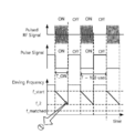
도 1은 통상적인 주파수 튜닝(frequency tuning)하여 또는 주파수 가변하여 임피던스 매칭을 수행하는 예를 나타낸다.1 shows an example of performing impedance matching by conventional frequency tuning or by varying the frequency.
도 1을 참조하면, 가변 주파수 RF 전원은 교번하는 온타임 구간(T_ON)과 오프 타임 구간(T_OFF)으로 RF 전력을 부하에 전달한다. 온타임 구간(T_ON)이 수 msec 이상으로 충분한 경우, 상기 가변 주파수 RF 전원의 구동 주파수는 온타임 구간(T_ON) 마다 시작 구동 주파수(f_start)에서 시작하여 소정의 시간 내에서 매칭 주파수(f_match)에서 임피던스 매칭을 수행한다. 하나의 펄스의 온타임 구간 내에서 주파수 튜닝(Frequency Tuning)이 정상적으로 수행된다. Referring to FIG. 1, the variable frequency RF power transfers RF power to a load in alternating on-time periods T_ON and off-time periods T_OFF. When the on-time period (T_ON) is sufficient for several msec or more, the driving frequency of the variable frequency RF power starts at the start driving frequency (f_start) for each on-time period (T_ON) and at the matching frequency (f_match) within a predetermined time. Impedance matching is performed. Frequency tuning is normally performed within the on-time period of one pulse.
도 2는 통상적인 주파수 튜닝(frequency tuning)하여 또는 주파수 가변하여 임피던스 매칭을 수행하는 예를 나타낸다.2 shows an example in which impedance matching is performed by conventional frequency tuning or by varying the frequency.
도 2를 참조하면, 가변 주파수 RF 전원은 교번하는 온타임 구간(T_ON)과 오프 타임 구간(T_OFF)으로 RF 전력을 부하에 전달한다. 온타임 구간(T_ON)이 1 msec 이하로 시간이 충분하지 못한 경우, 상기 가변 주파수 RF 전원의 구동 주파수는 온타임 구간(T_ON) 마다 시작 구동 주파수(f_start)에서 시작하여 온타임 구간(T_ON) 내에서 매칭 주파수(f_match)에 도달하지 못하여 임피던스 매칭을 수행하지 못한다.Referring to FIG. 2, the variable frequency RF power transfers RF power to a load in alternate on-time periods T_ON and off-time periods T_OFF. When the on-time period (T_ON) is less than 1 msec and the time is insufficient, the driving frequency of the variable frequency RF power starts from the start driving frequency (f_start) for each on-time period (T_ON) and falls within the on-time period (T_ON). Impedance matching cannot be performed because the matching frequency (f_match) is not reached at.
도 3은 통상적인 주파수 튜닝(frequency tuning)하여 또는 주파수 가변하여 임피던스 매칭을 수행하는 예를 나타낸다.3 shows an example of performing impedance matching by conventional frequency tuning or by varying the frequency.
도 3을 참조하면, 가변 주파수 RF 전원은 교번하는 온타임 구간(T_ON)과 오프 타임 구간(T_OFF)으로 RF 전력을 부하에 전달한다. 온타임 구간(T_ON)이 1 msec 이하로 충분하지 못한 경우, 상기 가변 주파수 RF 전원의 구동 주파수는 제1 온타임 구간(T_ON)에서 제1 시작 구동 주파수(f_start)에서 시작하여 온타임 구간(T_ON) 내에서 매칭 주파수(f_match)에 도달하지 못하여 임피던스 매칭을 수행하지 못한다. 하지만, 제2 온타임 구간에서 제1 온타임 구간의 최종 주파수를 제2 시작 구동 주파수로 설정하여, 제2 온타임 구간에서 연속적으로 구동 주파수를 가변하면서 임피던스를 매칭한다. 결국, 제i 온타임 구간에서 주파수를 가변하여 매칭 주파수(f_match)에 도달하여 임피던스 매칭을 수행한다.Referring to FIG. 3, the variable frequency RF power transfers RF power to a load in alternate on-time periods T_ON and off-time periods T_OFF. When the on-time period (T_ON) is less than 1 msec, the driving frequency of the variable frequency RF power starts from the first start driving frequency (f_start) in the first on-time period (T_ON) and the on-time period (T_ON). ), impedance matching cannot be performed because the matching frequency (f_match) is not reached. However, by setting the final frequency of the first on-time period as the second start driving frequency in the second on-time period, the impedance is matched while continuously varying the driving frequency in the second on-time period. As a result, impedance matching is performed by varying the frequency in the ith on-time interval to reach the matching frequency f_match.
그러나, 이와 같은 방식의 임피던스 매칭 방법은 주파수 가변 임피던스 매칭을 수행하기 위하여 복수의 펄스를 요구한다. 따라서, 고속의 효율적인 펄스형 가변 주파수 RF 발생기의 임피던스 매칭 방법이 요구된다.However, such an impedance matching method requires a plurality of pulses to perform frequency variable impedance matching. Accordingly, there is a need for an impedance matching method of a high-speed and efficient pulse-type variable frequency RF generator.
본 발명의 일 실시예에 따른 주파수 튜닝 임피던스 매칭 방법은 사용자가 설정한 시작 구동 주파수(Start Driving Frequency)와 RF 출력신호를 분석하여 구동 주파수를 변경한다. 구체적으로, n 번째 펄스 내에서 측정된 어디미턴스의 허수부인 서셉턴스를 이용하여 다음 주파수를 예측할 수 있다. 이에 따라, 임피던 매칭이 고속으로 수행되거나, 고속으로 최적 주파수에 도달할 수 있다. The frequency tuning impedance matching method according to an embodiment of the present invention changes a driving frequency by analyzing a start driving frequency set by a user and an RF output signal. Specifically, the next frequency can be predicted using the susceptance, which is the imaginary part of the wheremittance measured in the nth pulse. Accordingly, impedance matching may be performed at a high speed or an optimum frequency may be reached at a high speed.
이하, 첨부한 도면들을 참조하여 본 발명의 바람직한 실시예들을 상세히 설명하기로 한다. 그러나, 본 발명은 여기서 설명되어지는 실시예들에 한정되지 않고 다른 형태로 구체화될 수도 있다. 오히려, 여기서 소개되는 실시예는 개시된 내용이 철저하고 완전해질 수 있도록 그리고 당업자에게 본 발명의 사상이 충분히 전달될 수 있도록 하기 위해 제공되어지는 것이다. 도면들에 있어서, 구성요소는 명확성을 기하기 위하여 과장되어진 것이다. 명세서 전체에 걸쳐서 동일한 참조번호로 표시된 부분들은 동일한 구성요소들을 나타낸다.Hereinafter, exemplary embodiments of the present invention will be described in detail with reference to the accompanying drawings. However, the present invention is not limited to the embodiments described herein and may be embodied in other forms. Rather, the embodiments introduced herein are provided so that the disclosed contents may be thorough and complete, and the spirit of the present invention may be sufficiently conveyed to those skilled in the art. In the drawings, components are exaggerated for clarity. Parts indicated by the same reference numerals throughout the specification represent the same elements.
도 4는 본 발명의 일 실시예에 따른 펄스형 가변 주파수 RF 발생기 및 부하를 나타내는 회로도이다.4 is a circuit diagram showing a pulsed variable frequency RF generator and a load according to an embodiment of the present invention.
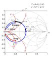
도 5는 도 4에서 펄스형 가변 주파수 RF 발생기의 출력단에서 부하를 바라본 임피던스를 표시하는 스미스 차트(Smith Chart)이다.FIG. 5 is a Smith chart showing the impedance viewed from the output terminal of the pulsed variable frequency RF generator in FIG. 4 as viewed from the load.
도 4 및 도 5를 참조하면, 펄스형 가변 주파수 RF 발생기(110)는 전송선(120)을 통하여 임피던스 매칭 네트워크(130)와 부하(140)에 RF 전력을 부하(140)에 전달한다. 임피던스 매칭 네트워크(130)와 부하(140)를 바라본 임피던스는 Z'이다. 펄스형 가변 주파수 RF 발생기(110)의 출력단(N1)에서 전송선(120), 임피던스 매칭 네트워크(130)와 부하(140)를 바로본 임피던스는 Zi이다. 제1 임피던스(Zi)는 제1 어드미턴스(Yi=1/Zi)로 변환되고, 제2 임피던스(Z')는 제2 어드미턴스(Y')로 변환될 수 있다. 또한, 제2 어드미턴스(Y')는 규격화된 어드미턴스(y'=ZO Y'= g'+ib')로 표시될 수 있다. 여기서 ZO는 전송선(120)의 특성 임피던스이다. 여기서 g'은 컨덕턴스이고, b'은 서셉턴스이다.4 and 5, the pulsed variable
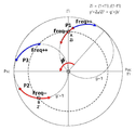
임피던스 매칭 지점은 스미스 차트의 원점으로 반사계수(Γ)가 영인 지점이다. 임피던스 매칭 네트워크(130)의 입력단(N1)에 바라본 제2 임피던스(Z')의 실수부가 50 오옴으로 고정된 경우, g'=1인 컨덕턴스 서클(conductance circle)은 원점과 Psc를 지름으로 하는 원이다. 펄스형 가변 주파수 RF 발생기(110)의 구동 주파수가 증가하는 경우, 스미스 차트의 P3 지점은 g'=1인 컨덕턴스 서클(conductance circle)을 따라 시계 방향으로 회전한다. 펄스형 가변 주파수 RF 발생기(110)의 구동 주파수가 감소하는 경우, 스미스 차트의 P2 지점은 g=1인 컨덕턴스 서클(conductance circle)을 따라 시계 방향으로 회전한다.
The impedance matching point is the point where the reflection coefficient (Γ) is zero as the origin of the Smith chart. When the real part of the second impedance Z'viewed from the input terminal N1 of the
한편, 제1 임피던스(Zi)는 제2 임피던스(Z')에 비하여 전송선(130)에 의한 위상 차이(φ)를 추가적으로 가진다. 제2 임피던스(Z')에 대하여, g'=1인 컨덕턴스 서클(conductance circle)은 스미스 차트 상에 시계 방향으로 회전한다. 위상 차이(φ)는 구동 각주파수(ω) 및 전송선(120)의 길이(d)에 비례하고, 전자파의 속도(c)에 반비례한다. 상기 전송선의 특성 임피던스는 Z0 이다. Meanwhile, the first impedance Zi additionally has a phase difference φ due to the
제2 반사계수(Γ')의 허수부가 양의 값을 가지는 경우, 구동 주파수를 증가시키면, 최소 경로를 따라 스미스 차트의 원점으로 이동하여 임피던스 매칭을 수행한다. 한편, 제2 반사계수(Γ')의 허수부가 음의 값을 가지는 경우, 구동 주파수를 감소시키어 최소 경로를 따라 스미스 차트의 원점으로 이동하여 임피던스 매칭을 수행한다.When the imaginary part of the second reflection coefficient Γ'has a positive value, when the driving frequency is increased, impedance matching is performed by moving to the origin of the Smith chart along the minimum path. Meanwhile, when the imaginary part of the second reflection coefficient Γ'has a negative value, the driving frequency is reduced to move to the origin of the Smith chart along the minimum path to perform impedance matching.
제1 임피던스(Zi)에 대하여, g=1인 컨덕턴스 서클(conductance circle) 상에 있는 P1 지점은 구동 주파수가 증가하면 시계 방향으로 회전하고, 구동 주파수가 감소하면 반시계 방향으로 회전한다.With respect to the first impedance Zi, a point P1 on a conductance circle of g=1 rotates clockwise when the driving frequency increases, and rotates counterclockwise when the driving frequency decreases.
따라서, 주파수 튜닝 임피던스 매칭을 위하여 구동 주파수의 증가 또는 감소를 용이하게 판단하기 위하여, 반사계수(Γi)는 위상 차이(φ) 만큼 회전할 수 있다. 구체적으로, A 지점은 위상 변환에 의하여 B 지점으로 변환될 수 있다. 이에 따라, 반사계수(Γ')의 허수부의 부호에 따라 구동 주파수의 증가 또는 감소를 결정할 수 있다.Therefore, in order to easily determine the increase or decrease of the driving frequency for frequency tuning impedance matching, the reflection coefficient Γi may be rotated by the phase difference φ. Specifically, point A may be transformed into point B by phase transformation. Accordingly, it is possible to determine an increase or decrease in the driving frequency according to the sign of the imaginary part of the reflection coefficient Γ'.
제1 임피던스(Zi)에 대응하는 P1 위치에서 구동 주파수를 증가시키면 임피던스 특성에 따라 P1을 관통하는 원을 따라 시계방향으로 움직인다. 구동 주파수를 감소시키면 반시계방향으로 움직인다. 이러한 원리로 구동 주파수를 튜닝하여 스미스 차트 상의 원점에 제일 가까운 곳까지 이동하면, 임피던스 매칭이 수행된다.When the driving frequency is increased at the position P1 corresponding to the first impedance Zi, it moves clockwise along a circle passing through P1 according to the impedance characteristic. Decreasing the driving frequency moves counterclockwise. Impedance matching is performed when the driving frequency is tuned according to this principle and moved to the closest point to the origin on the Smith chart.
P1 위치에서 최단 거리로 임피던스를 매칭하기 위해서는 스미스 차트 상의 원점과 P1의 특성원의 중심을 지나는 선을 기준으로 위쪽에 있으면, 주파수를 감소시키고, 아래쪽에 있으면 주파수를 증가시키는 것이 유리하다.In order to match the impedance from the P1 position to the shortest distance, it is advantageous to decrease the frequency if it is above the line passing through the center of the origin on the Smith chart and the center of the characteristic circle of P1, and increase the frequency if it is below it.
최단 궤적을 쉽게 찾기 위해서는 g=1인 컨덕턴스 서클(conductance circle) 에 φ 만큼 각도를 제공하면, 원의 중심과 스미스 차트의 중심을 지나는 선이 X축(반사계수의 실수부 축)과 일치된다. 이에 따라, 반사계수(Γ')의 허수 성분이 양이냐 음이냐에 따라 최적의 궤적 방향을 결정할 수 있다. P1 지점의 반사계수에 위상은 φ이고, 크기는 1인 복소수를 곱한다. 따라서, 반사계수(Γ')의 허수 성분이 양인 P3 위치는 구동 주파수를 증가시키는 것이 유리하다. 또한, 반사계수(Γ')의 허수 성분이 음인 P2 위치는 구동 주파수를 감소시키는 것이 유리하다.To easily find the shortest trajectory, if you provide an angle as much as φ to a conductance circle with g=1, the center of the circle and the line passing through the center of the Smith chart coincide with the X axis (the real axis of the reflection coefficient). Accordingly, an optimal trajectory direction can be determined according to whether the imaginary component of the reflection coefficient Γ'is positive or negative. The reflection coefficient at point P1 is multiplied by a complex number with a phase of φ and a magnitude of 1. Therefore, it is advantageous to increase the driving frequency at the position P3 where the imaginary component of the reflection coefficient Γ'is positive. In addition, it is advantageous to reduce the driving frequency at the position P2 where the imaginary component of the reflection coefficient Γ'is negative.
도 6은 본 발명의 다른 실시예에 따른 펄스형 가변 주파수 RF 발생기 및 부하를 나타내는 회로도이다.6 is a circuit diagram showing a pulsed variable frequency RF generator and a load according to another embodiment of the present invention.
도 7은 도 6의 펄스형 가변 주파수 RF 발생기의 동작을 나타내는 흐름도이다.7 is a flowchart illustrating the operation of the pulsed variable frequency RF generator of FIG. 6.
도 8은 도 6의 펄스형 가변 주파수 RF 발생기의 펄스형 RF 신호, 펄스 발생기 펄스 상태 신호, 및 구동 주파수를 나타낸다.8 shows a pulsed RF signal, a pulse generator pulse state signal, and a driving frequency of the pulsed variable frequency RF generator of FIG. 6.
도 9는 스미스 차트 상에서 구동 주파수에 따른 어드미턴스를 나타낸다.9 shows the admittance according to the driving frequency on the Smith chart.
도 10은 구동 주파수에 따른 어드미턴스의 허수부를 나타낸다.10 shows an imaginary part of admittance according to a driving frequency.
도 11은 제어 루프의 동작 시간에 따른 구동 주파수의 변화를 나타낸다.11 shows the change of the driving frequency according to the operation time of the control loop.
도 6 내지 도 11을 참조하면, 펄스형 가변 주파수 RF 전원 시스템(100)은 펄스형 가변 주파수 RF 발생기(110), 상기 펄스형 가변 주파수 RF 발생기(110)와 부하(140) 사이에 배치된 임피던스 매칭 네트워크(130)를 포함한다. 상기 펄스형 가변 주파수 RF 발생기(110)는 교번하는 온타임 구간(T_ON)과 오프 타임 구간(T_OFF)으로 RF 전력을 부하(140)에 제공한다. 상기 임피던스 매칭 네트워크(130)는 적어도 2 개의 가변 리액턴스 소자(C1,C2)를 포함한다. 상기 임피던스 매칭 네트워크(130)의 가변 리액턴스 소자의 리액턴스 값을 변경하여 상기 부하 방향의 임피던스를 조절한다.6 to 11, the pulsed variable frequency
상기 펄스형 가변 주파수 RF 발생기(110)는 임피던스 감지부(115), 임피던스 처리부(111), 구동 주파수 예측부(117), 구동 주파수 제어부(113), 펄스 발생기(116), 및 RF 증폭기(114)를 포함할 수 있다. 상기 펄스형 가변 주파수 RF 발생기(110)는 구동 주파수를 변경하여 고속으로 임피던스 매칭 또는 최적의 주파수에서 동작한다.The pulsed variable
임피던스 감지부(115)는 n 번째 온타임 구간(T_ON(n))에서 상기 펄스형 가변 주파수 RF 발생기(110)의 출력단(N1)에 배치되어 RF 전류 신호(I) 및 RF 전압 신호(V)를 감지한다. n은 펄스의 순번이다.The
임피던스 처리부(111)는 n 번째 온타임 구간(T_ON(n))에서 상기 RF 전류 신호(I) 및 상기 RF 전압 신호(V)를 이용하여 상기 펄스형 가변 주파수 RF 발생기(110)의 출력단(N1)에서의 임피던스(Zi) 및 반사계수(Γi), 상기 부하(140)와 펄스형 가변 주파수 RF 발생기(110) 사이의 전송선(120)에 의한 위상 이동된 반사계수(Γ'), 그리고 상기 위상 이동된 반사계수(Γ')에서 변환된 위상 이동된 어드미턴스(y')를 산출한다.The
구동 주파수 예측부(117)는 n 번째 온타임 구간(T_ON(n))에서 측정된 구동 주파수에 따른 상기 위상 이동된 어드미턴스(y')를 이용하여 다음 온타임 구간(T_ON(n+1))의 구동 주파수를 예측한다. The driving
구동 주파수 제어부(113)는 상기 예측된 구동 주파수를 다음 온타임 구간(T_ON(n+1))의 시작 구동 주파수로 설정하고 상기 위상 이동된 반사계수(Γ')를 이용하여 구동 주파수를 제어한다.The driving
펄스 발생기(116)는 펄스 신호를 생성하여 온타임 구간(T_ON)과 오프 타임 구간(T_OFF)을 구분하고 상기 펄스 신호를 상기 구동 주파수 예측부(117) 및 상기 구동 주파수 제어부(113)에 제공한다.The pulse generator 116 generates a pulse signal to separate the on-time period (T_ON) and the off-time period (T_OFF), and provides the pulse signal to the driving
RF 증폭기(114)는 상기 구동 주파수 제어부의 구동 주파수에서 정현파를 증폭시키어 RF 신호를 출력한다.The
부하(140)는 축전 결합 플라즈마를 형성하는 전극 또는 유도 결합 플라즈마를 형성하는 안테나일 수 있다. 상기 부하(140)는 반도체 공정을 처리하는 챔버 내부 또는 외부에 장착될 수 있다. 상기 부하(140)는 상기 펄스 신호에 동기화되어 펄스 플라즈마를 형성할 수 있다. 구동 주파수는 수 MHz 내지 수십 MHz일 수 있다. 펄스 주파수는 수 kHz 내지 수십 kHz일 수 있다. RF 펄스의 온 듀티 비(On Duty Ratio)는 수 퍼센트 내지 수십 퍼센트일 수 있다. 온타임 구간(T_ON)은 500 usec 이하일 수 있다. 바람직하게는, 온타임 구간(T_ON)은 100 usec 이하일 수 있다. The
임피던스 매칭 네트워크(130)는 가변 리액티브 소자의 연결 방식에 따라 다양한 유형으로 분류될 수 있다. 예시적으로, 임피던스 매칭 네트워크(130)는 부하에 직렬 연결된 제1 가변 축전기(C1)와 상기 직렬 연결된 제1 가변 축전기(C1)와 부하(140)에 병렬 연결된 제2 가변 축전기(C2)를 포함할 수 있다. 상기 임피던스 매칭 네트워크(130)는 L-형, 역 L-형(inverted L-type), T-형, 또는 π-형일 수 있다. 상기 임피던스 매칭 네트워크(130)는 상기 펄스형 가변 주파수 RF 발생기(110)의 구동 주파수의 튜닝에 의한 임피던스 매칭에 실패한 경우 동작하여 임피던스 매칭을 수행할 수 있다.The
임피던스 감지부(115)는 상기 펄스형 가변 주파수 RF 발생기(110)의 출력단(N1)에서 부하 방향의 RF 전류 신호(I) 및 RF 전압 신호(V)를 측정한다. 상기 RF 전류 신호(I) 및 RF 전압 신호(V)는 상기 구동 주파수의 주기 이상의 샘플링 시간 동안 상기 구동 주파수보다 높은 샘플링 레이트(sampling rate)로 샘플링되어 디지털 신호로 변환되어 상기 임피던스 처리부(111)에 제공될 수 있다. The
임피던스 처리부(111)는 상기 RF 전류 신호(I) 및 RF 전압 신호(V)를 이용하여 상기 펄스형 가변 주파수 RF 발생기(110)의 출력단(N1)에서의 임피던스(Zi) 및/또는 반사계수(Γi)를 산출할 수 있다. 또한, 상기 임피던스 처리부(111)는 전송선(120)의 길이(d)에 의한 위상 차이(φ)를 보상할 수 있다. 구체적으로, 반사계수(Γi)는 임피던스 매칭 네트워크(130)의 입력단(N2)에서 부하(140)를 바라본 위상 이동된 반사계수(Γ')로 다음과 같이 변환될 수 있다.
[수학식 1][Equation 1]
Γ' = Γi ejφ Γ '= Γi e jφ
φ= ωd/c φ= ωd/c
여기서, φ는 위상 차이이고, d는 전송선의 길이이고, ω는 구동 각주파수이고, c는 전송선에서 전자파의 속도이다. 상기 전송선(120)은 동축 케이블일 수 있다. 상기 위상 이동된 반사계수(Γ')는 상기 임피던스 매칭 네트워크(130)의 입력단(N2)에서 부하를 바라본 반사계수이다.Here, φ is the phase difference, d is the length of the transmission line, ω is the driving angular frequency, and c is the speed of the electromagnetic wave in the transmission line. The
임피던스 처리부(111)는 위상 이동된 반사계수(Γ')를 위상 이동된 어드미턴스(y')로 변환할 수 있다. 위상 이동된 어드미턴스(y')는 다음과 같이 주어질 수 있다.The
[수학식 2][Equation 2]
y' = g' + jb'y'= g'+ jb'
여기서, g'은 컨덕턴스이고, b'은 서셉턴스이다.Here, g'is conductance, and b'is susceptance.
상기 구동 주파수 제어부(117)는 상기 위상 이동된 반사계수(Γ')를 제공받을 수 있다. 상기 구동 주파수 제어부(117)는 온타임 구간(T_ON)을 복수의 단위 시간 (Δt)으로 분할하여, 단위 시간(Δt) 마다 구동 주파수를 변경할 수 있다. 단위 시간(Δt)은 제어 루프의 동작 시간으로 약 1 usec 수준일 수 있다. 따라서, 제어루프의 총 개수(q)는 T_ON/Δt 이다. 여기서, q는 3 이상의 양의 정수이다.The
상기 구동 주파수 제어부(117)는 상기 위상 이동된 반사 계수의 허수부(Im(Γ'))의 부호에 따라 구동 주파수의 증감 방향을 선택할 수 있다. 구체적으로, 반사 계수의 허수부(Im(Γ'))가 양의 값을 가지는 경우, 상기 구동 주파수를 주파수 변화량(df) 만큼 증가시킬 수 있다. 또한, 상기 반사 계수의 허수부(Im(Γ'))가 음의 값을 가지는 경우, 상기 구동 주파수를 주파수 변화량(df) 만큼 감소시킬 수 있다. 주파수 변화량(df)은 반사계수의 절대값(|Γ'|) 또는 반사계수의 허수부(Im(Γ'))의 크기에 의존할 수 있다. 예를 들어, 상기 주파수 변화량(df)은 반사계수의 절대값(|Γ'|) 또는 반사계수의 허수부(Im(Γ'))의 크기에 비례할 수 있다. 예를 들어, 상기 구동 주파수 제어부(117)는 상기 반사 계수의 절대값(|Γ'|)이 문턱값 이하로 임피던스 매칭이 수행된 경우에는 구동 주파수를 변경하지 않을 수 있다. 상기 구동 주파수 제어부(117)는 임피던스 매칭 정도에 따라 주파수 변화량(df)을 조절할 수 있다.
The
상기 구동 주파수 제어부(117)는 비례-적분-미분 제어 방식을 사용할 수 있다. 상기 구동 주파수 제어부(117)는 온타임 구간(T_ON)에 구동 주파수를 출력하고, 오프 타임 구간(T_OFF)에 구동 주파수를 출력하지 않을 수 있다. The driving
상기 RF 증폭기(114)는 상기 구동 주파수로 RF 출력을 제공할 수 있다. RF 증폭기(114)는 RF 전력 증폭기일 수 있다. 상기 RF 증폭기(114)의 출력은 수백 와트 내지 수십 킬로와트일 수 있다.The
펄스 발생기(116)는 상기 온타임 구간(T_ON)과 오프 타임 구간(T_OFF)을 식별하기 위한 펄스 신호를 상기 구동 주파수 제어부(113) 및 구동 주파수 예측부(117)에 제공할 수 있다. 상기 펄스 발생기(116)의 주파수는 수 kHz 내지 수십 kHz일 수 있다. 상기 구동 주파수가 13. 56 MHz의 범위에 있는 경우, 상기 온타임 구간(T_ON) 및 상기 오프 타임 구간(T_OFF)은 각각 100 usec 수준일 수 있다. 제어 루프의 동작 시간 또는 단위 시간(Δt)은 약 1 usec 수준일 수 있다. The pulse generator 116 may provide a pulse signal for identifying the on-time period T_ON and the off-time period T_OFF to the driving
구동 주파수 예측부(117)는 첫 번째 펄스의 시작 주파수(f_start)를 제공받을 수 있다. 또한, 최적 조건을 판단하기 위한 문턱값을 제공받을 수 있다. 또한, 주파수 예측을 수행하는 제어루프의 특정 회수(m=r) 또는 홀드-오프 타임을 제공받을 수 있다. 구동 주파수 예측부(117)는 위상 이동된 어드미턴스(y') 또는 서셉턴스(b')를 제공받을 수 있다. 상기 구동 주파수 예측부(117)는 n 번째 온타임 구간(T_ON(n))에서 구동 주파수에 따른 위상 이동된 어드미턴스(y')의 허수부(b')를 직선 피팅하여 위상 이동된 어드미턴스(y')의 허수부(b')가 영인 지점에 대응하는 주파수를 예측 구동 주파수로 설정할 수 있다.The
상기 다음 온타임 구간(T_ON(n+1))의 상기 예측된 구동 주파수(f(n+1,1))는 다음과 같이 주어질 수 있다. The predicted driving frequency f(n+1,1) of the next on-time period T_ON(n+1) may be given as follows.
[수학식 3][Equation 3]
f(n+1,m=1) = f(n,m=r) - b'(n,m=r) [df(n,m=r)/db'(n,m=r)]f(n+1,m=1) = f(n,m=r)-b'(n,m=r) [df(n,m=r)/db'(n,m=r)]
df(n,m=r)/db'(n,m=r)= [f(n,m=q)-f(n,m=r)]/[b'(n,m=q)-b'(n,m=r)])df(n,m=r)/db'(n,m=r)= [f(n,m=q)-f(n,m=r)]/[b'(n,m=q)- b'(n,m=r)])
으로 주어지고,Given by,
여기서, f(n,m=r)는 n 번째 펄스의 온타임 구간(T_ON(n))에서 소정의 r 번째 처리 회수에서 구동 주파수이다. b'(n,m=r)은 n 번째 펄스의 온타임 구간(T_ON(n))의 소정의 r 번째 처리 회수에서 상기 위상 이동된 어드미턴스(y')의 허수부인 서셉턴스이다. f(n,m=q)는 n 번째 펄스의 온타임 구간(T_ON(n))에서 마지막 처리 회수에서 구동 주파수이다. b'(n,m=q)은 n 번째 펄스의 온타임 구간(T_ON(n))의 마지막 처리 회수의 어드미턴스(y')의 허수부인 서셉턴스이다. r은 3 내지 q-1의 양의 정수일 수 있다. 제어 루프의 총 개수(q)는 T_ON/Δt 이다. q는 3 이상의 양의 정수이다. Here, f(n,m=r) is the driving frequency at a predetermined r-th processing number in the on-time period T_ON(n) of the n-th pulse. b'(n,m=r) is the susceptance, which is the imaginary part of the admittance y', which has been phase-shifted at a predetermined r-th processing number of the on-time period T_ON(n) of the n-th pulse. f(n,m=q) is the driving frequency at the last number of processing times in the on-time period (T_ON(n)) of the nth pulse. b'(n,m=q) is the susceptance which is the imaginary part of the admittance (y') of the last number of processing times in the on-time period (T_ON(n)) of the nth pulse. r may be a positive integer of 3 to q-1. The total number of control loops (q) is T_ON/Δt. q is a positive integer of 3 or more.
구동 주파수 예측부(117)는 예측된 구동 주파수(f(n+1,m=1))를 상기 구동 주파수 제어부(113)에 제공하여, n+1 번째 온타임 구간(T_ON(n))의 시작 구동 주파수로 동작할 수 있다. 이에 따라, 고속 주파수 튜닝 임피던스 매칭이 수행될 수 있다.The driving
이하, 펄스형 가변 주파수 RF 발생기의 임피던스 매칭 방법이 설명된다. Hereinafter, an impedance matching method of a pulsed variable frequency RF generator will be described.
다시, 도 7을 참조하면, 본 발명의 일 실시예에 따른 펄스형 가변 주파수 RF 발생기(110)는 교번하는 온타임 구간(T_ON)과 오프 타임 구간(T_OFF)의 펄스로 RF 전력을 부하(140)에 제공하고, 상기 온타임 구간(T_ON) 내에서 구동 주파수를 변경하는 제어 루프를 포함한다.Again, referring to FIG. 7, the pulsed variable
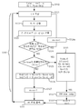
펄스형 가변 주파수 RF 발생기(110)의 임피던스 매칭 방법은, n 번째 펄스의 온타임 구간(T_ON(n))에서 구동 주파수(f(n,m))를 변경하는 단계(S101); 상기 n 번째 펄스의 온타임 구간(T_ON(n))의 어드미턴스를 이용하여 n+1 번째 펄스의 온타임 구간(T_ON(n+1))의 구동 주파수를 예측하는 단계(S301); 및 n+1 번째 펄스의 온타임(T_ON(n+1))에서 상기 예측된 구동 주파수(f(n+1,1))로 상기 펄스형 가변 주파수 RF 발생기(110)의 RF 출력을 제공하는 단계(S141)를 포함한다. 여기서, f(n,m)은 n 번째 펄스의 온타임 구간(T_ON(n)) 내에서 m 번째 처리 회수(또는 제어 루프)에서 구동 주파수이다. n은 펄스의 순번을 나타낸다. m은 1 내지 q 사이의 양의 정수이다. 제어루프의 총 개수(q)는 T_ON/Δt 이다. 여기서, q는 3 이상의 양의 정수이다. m은 온타임 구간(T_ON) 내에서 구동 주파수의 변경을 위한 상기 제어 루프의 처리 회수를 나타내는 인덱스를 나타낸다.The impedance matching method of the pulsed variable
우선, 첫 번째 펄스의 시작 구동 주파수(f_start), 펄스의 튜티 비, 펄스의 주기, 하나의 펄스 내에서 제어 루프의 총개수(q), 제어루프의 동작 시간(Δt) 및 제어 루프의 처리 회수를 나타내는 인덱스(m)의 초기값이 설정된다(S110). First, the start driving frequency of the first pulse (f_start), the duty ratio of the pulse, the period of the pulse, the total number of control loops in one pulse (q), the operation time of the control loop (Δt), and the number of processing of the control loop. The initial value of the index (m) is set (S110).
n 번째 펄스의 온타임 구간(T_ON(n))에서 구동 주파수(f(n,m))를 변경하는 단계(S101)는, 제1 단계(S121), 제2 단계(S122, S123), 그리고 제3 단계(S126)을 포함한다.The step (S101) of changing the driving frequency (f(n,m)) in the on-time period (T_ON(n)) of the nth pulse (S101) includes a first step (S121), a second step (S122, S123), and It includes a third step (S126).
S121 단계에서, n 번째 펄스의 온타임 구간(T_ON(n))에서 상기 펄스형 가변 주파수 RF 발생기(110)의 출력단에서 RF 전류 신호(I) 및 RF 전압 신호(V)를 측정한다. 상기 RF 전류 신호(I) 및 RF 전압 신호(V)는 임피던스 감지부(115)에 감지될 수 있다. In step S121, the RF current signal I and the RF voltage signal V are measured at the output terminal of the pulsed variable
S122 및 S123 단계에서, n 번째 펄스의 온타임 구간(T_ON(n))에서에서 상기 RF 전류 신호(I) 및 상기 RF 전압 신호(V)를 이용하여 상기 펄스형 가변 주파수 RF 발생기의 출력단에서 임피던스(Zi), 반사계수(Γi), 및 전송선에 의한 위상을 반영한 위상 이동된 반사계수(Γ'), 위상 이동된 어드미턴스(y')를 산출한다. 위상 이동된 반사계수(Γ')는 수학식 1에 의하여 연산될 수 있다. 임피던스 처리부(111)는 임피던스(Zi), 반사계수(Γi), 및 전송선에 의한 위상을 반영한 위상 이동된 반사계수(Γ'), 위상 이동된 어드미턴스(y')를 산출할 수 있다.In steps S122 and S123, impedance at the output terminal of the pulse-type variable frequency RF generator using the RF current signal I and the RF voltage signal V in the on-time period T_ON(n) of the nth pulse (Zi), the reflection coefficient (Γi), the phase shifted reflection coefficient (Γ') reflecting the phase of the transmission line, and the phase shifted admittance (y') are calculated. The phase shifted reflection coefficient Γ'may be calculated by
S124 단계에서, 상기 위상 이동된 반사계수(Γ')를 이용하여 임피던스 매칭을 위한 최적 조건을 판단할 수 있다. 상기 구동 주파수 제어부는 상기 위상 이동된 반사계수(Γ')를 이용하여 임피던스 매칭을 위한 최적 조건을 판단할 수 있다. 상기 최적 조건은 상기 위상 이동된 반사계수의 절대값(|Γ'|) 또는 상기 위상 이동된 반사계수(Γ')의 허수부(Im(Γ'))의 크기로 판단될 수 있다. 상기 최적 조건인 경우, 구동 주파수의 변경을 위한 처리 회수를 나타내는 인덱스(m)을 증가시킨 후 상기 펄스형 가변 주파수 RF 발생기의 출력단에서 RF 전류 신호(I) 및 RF 전압 신호(V)를 측정하는 제1 단계(S121)를 수행할 수 있다. 상기 최적 조건이 아닌 경우, 상기 구동 주파수를 변경하는 제3 단계(S126)를 수행할 수 있다.In step S124, an optimum condition for impedance matching may be determined using the phase-shifted reflection coefficient Γ'. The driving frequency control unit may determine an optimum condition for impedance matching using the phase-shifted reflection coefficient Γ'. The optimal condition may be determined by the magnitude of the absolute value (|Γ'|) of the phase-shifted reflection coefficient or the imaginary part (Im(Γ')) of the phase-shifted reflection coefficient (Γ'). In the case of the optimum condition, after increasing the index (m) representing the number of times of processing for changing the driving frequency, the RF current signal (I) and the RF voltage signal (V) are measured at the output terminal of the pulsed variable frequency RF generator. The first step S121 may be performed. If it is not the optimum condition, a third step (S126) of changing the driving frequency may be performed.
구체적으로, 상기 위상 이동된 반사계수의 허수부(Im(Γ'))가 문턱값 이내인 경우 (또는 임피던스 매칭이 완료된 경우), 구동 주파수의 변경을 위한 처리 회수를 나타내는 인덱스(m)을 증가시킨(S124a) 후 상기 펄스형 가변 주파수 RF 발생기의 출력단에서 RF 전류 신호(I) 및 RF 전압 신호(V)를 측정하는 제1 단계(S121)를 수행할 수 있다. 상기 위상 이동된 반사계수의 허수부(Im(Γ'))가 문턱값 이외에 있는 경우, 상기 구동 주파수를 변경하는 제3 단계(S126)를 수행할 수 있다.Specifically, when the imaginary part (Im(Γ')) of the phase-shifted reflection coefficient is within the threshold value (or when impedance matching is completed), the index (m) indicating the number of times of processing for changing the driving frequency is increased. After setting (S124a), a first step (S121) of measuring the RF current signal (I) and the RF voltage signal (V) at the output terminal of the pulsed variable frequency RF generator may be performed. When the imaginary part Im(Γ') of the phase-shifted reflection coefficient is other than the threshold value, a third step (S126) of changing the driving frequency may be performed.
제3 단계(S126)에서, n 번째 온타임 구간(T_ON(n))에서 상기 위상 이동된 반사 계수의 허수부(Im(Γ'))의 부호에 따라 상기 펄스형 가변 주파수 RF 발생기의 구동 주파수의 증감 방향을 선택하고 상기 구동 주파수를 변경한다. 구체적으로, 상기 위상 이동된 반사 계수의 허수부(Im(Γ'))가 양의 값을 가지는 경우 구동 주파수는 증가하고, 상기 위상 이동된 반사 계수의 허수부(Im(Γ'))가 음의 값을 가지는 경우 구동 주파수는 감소시킨다. 상기 구동 주파수의 변화량(df)는 반사계수의 절대값(|(Γ')|) 또는 반사계수의 허수부(Im(Γ'))의 크기에 의존할 수 있다. In the third step (S126), the driving frequency of the pulsed variable frequency RF generator according to the sign of the imaginary part (Im(Γ')) of the phase-shifted reflection coefficient in the n-th on-time period (T_ON(n)) Select the direction of increase or decrease and change the driving frequency. Specifically, when the imaginary part (Im(Γ')) of the phase-shifted reflection coefficient has a positive value, the driving frequency increases, and the imaginary part (Im(Γ')) of the phase-shifted reflection coefficient is negative. When it has a value of, the driving frequency is reduced. The change amount df of the driving frequency may depend on the absolute value of the reflection coefficient (|(Γ')|) or the size of the imaginary part (Im(Γ')) of the reflection coefficient.
S125 단계에서, n 번째 펄스의 온타임 구간(T_ON(n))의 종료여부를 판단할 수 있다. 즉, m>q인 경우, 온타인 구간(T_ON(n))이 종료된다. 온타임 구간(T_ON(n))이 종료되지 않은 경우, S126 단계에서, n 번째 펄스의 온타임 구간(T_ON(n))에서 상기 위상 이동된 반사 계수의 허수부(Im(Γ'))의 부호에 따라 상기 펄스형 가변 주파수 RF 발생기의 구동 주파수의 증감 방향을 선택하여 상기 구동 주파수를 변경할 수 있다.In step S125, it may be determined whether the on-time period T_ON(n) of the n-th pulse is ended. That is, when m>q, the ontine section T_ON(n) ends. If the on-time period (T_ON(n)) is not finished, in step S126, the imaginary part (Im(Γ')) of the phase-shifted reflection coefficient in the on-time period (T_ON(n)) of the nth pulse The driving frequency may be changed by selecting an increase or decrease direction of the driving frequency of the pulsed variable frequency RF generator according to a sign.
n 번째 펄스의 온타임 구간(T_ON(n))이 종료시 까지 상기 제1 단계(S121), 상기 제2 단계(S122, S123), 및 상기 제3 단계(S126)는 반복될 수 있다.The first step (S121), the second step (S122, S123), and the third step (S126) may be repeated until the on-time period T_ON(n) of the n-th pulse ends.
온타임 구간(T_ON(n))이 종료된 경우(m>q), S131 단계에서, 상기 n 번째 펄스의 온타임 구간(T_ON(n))의 어드미턴스(y')를 이용하여 n+1 번째 펄스의 온타임 구간(T_ON(n+1))의 구동 주파수를 예측할 수 있다. S131 단계는, n 번째 온타임 구간(T_ON(n))에서 위상 이동된 어드미턴스(y')의 허수부를 구동 주파수에 따라 직선 피팅하는 단계; 및 상기 위상 이동된 어드미턴스(y')의 허수부가 영인 지점에 대응하는 주파수를 n+1 번째 펄스의 온타임 구간(T_ON(n+1))의 예측된 구동 주파수(f(n+1,1))로 설정하는 단계를 포함할 수 있다.When the on-time period (T_ON(n)) is ended (m>q), in step S131, the n+1-th using the admittance (y') of the on-time period (T_ON(n)) of the n-th pulse The driving frequency of the pulse on-time period T_ON(n+1) can be predicted. Step S131 includes: linearly fitting the imaginary part of the admittance y'phase-shifted in the n-th on-time period T_ON(n) according to the driving frequency; And a frequency corresponding to a point where the imaginary part of the phase-shifted admittance y'is zero is the predicted driving frequency f(n+1,1) of the on-time period (T_ON(n+1)) of the n+1th pulse. )) may include the step of setting.
상기 n+1 번째 펄스의 온타임 구간(T_ON(n+1))의 상기 예측 구동 주파수(f(n+1,m=1))는 [수학식 3]으로 주어질 수 있다. m=1인 경우, 펄스의 시작 시간으로 부하인 플라즈마의 안정성이 감소하여 불안정한 임피던스가 측정될 수 있다. 따라서, n+1 번째 펄스의 온타임 구간(T_ON(n+1))에서 사용할 예측된 구동 주파수는 소정의 r 번째 처리 회수에서 측정된 데이터와 마지막 q 번째 처리 회수에서 측정된 데이터를 처리하여 사용할 수 있다. 즉, r은 3 내지 q-1의 양의 정수일 수 있다. The predicted driving frequency (f(n+1,m=1)) of the on-time period T_ON(n+1) of the n+1 th pulse may be given by [Equation 3]. In the case of m=1, the stability of the plasma as a load decreases with the start time of the pulse, so that an unstable impedance can be measured. Therefore, the predicted driving frequency to be used in the on-time period of the n+1th pulse (T_ON(n+1)) is used by processing the data measured at the predetermined rth processing number and the data measured at the last qth processing number. I can. That is, r may be a positive integer of 3 to q-1.
n+1 번째 펄스의 온타임 구간(T_ON(n+1))의 구동 주파수를 예측한 후, 오프 타임 구간(T_OFF)을 위하여 시간 지연이 수행될 수 있다(S132).After predicting the driving frequency of the on-time period T_ON(n+1) of the n+1th pulse, a time delay may be performed for the off-time period T_OFF (S132).
이어서, 다음 펄스를 위하여, n=n+1으로 설정하고, 제어회로의 처리 회수 인덱스는 m=1로 설정한다(S133).Then, for the next pulse, n=n+1 is set, and the number of processing indexes of the control circuit is set to m=1 (S133).
이어서, n+1 번째 펄스의 온타임 구간(T_ON(n+1))의 예측 구동 주파수(f(n+1,1))로 RF 전력을 출력한다(S141).Subsequently, RF power is output at the predicted driving frequency f(n+1,1) of the on-time period T_ON(n+1) of the n+1th pulse (S141).
이어서, n+2 번째 펄스가 시작하기 전 까지, n+1 번째 펄스에서 제어 루프가 q회 반복된다.Then, the control loop is repeated q times in the n+1th pulse until the n+2th pulse starts.
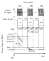
도 8을 참조하면, 펄스형 가변 주파수 RF 발생기(110)는 교번하는 온타임 구간(T_ON)과 오프 타임 구간(T_OFF)의 펄스로 RF 전력을 부하(140)에 제공한다. 펄스 발생기(110)는 교번하는 온타임 구간(T_ON)과 오프 타임 구간(T_OFF)의 펄스 신호를 생성한다. 상기 펄스 신호의 주기는 약 100 usec 수준일 수 있다.Referring to FIG. 8, the pulsed variable
상기 펄스형 가변 주파수 RF 발생기(110)의 구동 주파수는 첫 번째 펄스의 시작 구동 주파수(f_start)에서 시작하여, n번째 펄스의 m=1의 제어 루프에서, f(n,m=1))의 구동 주파수를 가진다. 시간에 따라, 상기 위상 이동된 반사 계수의 허수부(Im(Γ'))가 음의 값을 가지는 경우, 구동 주파수는 감소된다. m=r의 제어 루프 및 m=q의 제어 루프에서, 구동 주파수와 서셉턴스(b')를 사용하여, n+1 번째 펄스의 m=1의 제어 루프에서 사용할 구동 주파수(f(n+1,m=1))가 예측된다. 즉, 다음 펄스의 시작 구동 주파수는 이전 펄스의 구동 주파수와 서셉턴스(b')를 사용하여 예측된다. 이에 따라, 고속의 주파수 튜닝 임피던스 매칭 또는 최적 주파수 설정이 가능하다. 본 발명에 따르면, 1- 3 개의 펄스 내에서 임피던스 매칭이 완료된다. The driving frequency of the pulsed variable
도 9를 참조하면, 상기 펄스형 가변 주파수 RF 발생기(110)의 구동 주파수의 가변 범위는 12.88 MHz ~ 14.24 MHz일 수 있다. 매칭된 주파수는 13.56 MHz이고, 임피던스 매칭 네트워크(130)와 부하(140)를 포함하는 임피던스의 실수부(Z')는 50 오옴으로 설정되었다. 위상 이동된 반사계수(Γ') 또는 위상 이동된 어드미턴스(y')는 스미스 차트에 표시된다. 최적의 임피던스 매칭 위치는 반사계수(Γ')의 허수성분이 "0" 인 주파수이다. 스미스 차트 상에서, 12.88 MHz로부터 구동 주파수가 증가함에 서셉턴스(b')가 음의 값에서 영으로 증가한다. 한편, 14.24 MHz로부터 구동 주파수가 감소함에 따라 서셉턴스(b')가 양의 값에서 영으로 감소한다.Referring to FIG. 9, the variable range of the driving frequency of the pulsed variable
g'=1인 컨턱턴스 서클에서, 구동 주파수가 증가함에 따라 서클을 따라 시계 방향으로 회전하고, 서셉턴스(b')의 절대값이 점진적으로 영에 접근한다. 서셉턴스(b')의 절대값이 영에 도달하면, 임피던스가 매칭된다.In the conductance circle of g'=1, it rotates clockwise along the circle as the driving frequency increases, and the absolute value of susceptance (b') gradually approaches zero. When the absolute value of susceptance b'reaches zero, the impedance is matched.
도 10 및 도 11을 참조하면, 실선은, 부하(140) 및 임피던스 매칭 네트워크(130)의 임피던스(Z')의 실수부가 50 ohm인 경우, 구동 주파수에 따른 서셉턴스(b')를 표시한다. 12.88 MHz로부터 구동 주파수가 증가함에 서셉턴스(b')가 음의 값에서 영으로 증가한다. f(n,m=r)은 n번째 펄스의 온타임 구간(T_ON(n))에서의 m=r 번째의 제어 루프의 구동 주파수를 나타낸다. f_match는 임피던스가 매칭된 구동 주파수이다. 점선은 f(n,m=r)에서의 서셉턴스와 f(n,m=q)에서 서셉턴스를 연결하는 직선이다. 상기 직선이 영인 지점의 주파수가 n+1번째 펄스의 온타임 구간에서 예상되는 예측 매칭 주파수이다. 상기 접선의 서셉턴스(b')가 "0"이 되는 주파수f(n+1,m=1)가 예측 매칭 주파수이며, 다음 펄스의 시작 구동 주파수가 된다.10 and 11, a solid line indicates a susceptance b'according to a driving frequency when the real part of the impedance Z'of the
n번째 펄스의 온타임 구간의 데이터( 또는 서셉턴스)를 사용하여 얻어진 예측 구동 주파수를 n+1 번째 펄스의 온타임 구간의 시작 구동 주파수로 사용하면, 고속으로 주파수 튜닝 임피던스 매칭이 수행된다. When the predicted driving frequency obtained by using the data (or susceptance) of the on-time period of the nth pulse is used as the starting driving frequency of the on-time period of the n+1th pulse, frequency tuning impedance matching is performed at high speed.
도 12는 본 발명의 다른 실시예에 따른 구동 주파수에 따른 어드미턴스의 허수부를 나타낸다.12 shows an imaginary part of an admittance according to a driving frequency according to another embodiment of the present invention.
도 13은 도 12의 제어 루프의 동작 시간에 따른 구동 주파수의 변화를 나타낸다.13 shows a change in driving frequency according to the operation time of the control loop of FIG. 12.
도 12 및 도 13을 참조하면, 실선은, 부하 및 임피던스 매칭 네트워크의 임피던스(Z')의 실수부가 50 ohm인 경우, 구동 주파수에 따른 서셉턴스(b')가 표시된다. 12.88 MHz로부터 구동 주파수가 증가함에 서셉턴스(b')가 음의 값에서 영으로 증가한다. f(n,m=r)은 n번째 펄스의 온타임 구간(T_ON(n))에서의 m=r 번째의 제어 루프의 구동 주파수를 나타낸다. f_match는 임피던스가 매칭된 구동 주파수이다. 점선은 f(n,m=r)에서의 서셉턴스와 f(n,m=q)에서 서섭턴스를 연결하는 접선이다. 상기 접선이 영인 지점의 구동 주파수가 n+1번째 펄스의 온타임 구간에서 예상되는 예측 구동 주파수이다. 상기 접선의 서셉턴스(b')가 "0"이 되는 구동 주파수가 f(n+1,1)이다. f(n+1,1)는 f_match (13.56MHz)보다 크다. Referring to FIGS. 12 and 13, when the real part of the impedance Z'of the load and impedance matching network is 50 ohms, a susceptance b'according to the driving frequency is displayed. As the drive frequency increases from 12.88 MHz, the susceptance (b') increases from negative to zero. f(n,m=r) denotes the driving frequency of the m=r-th control loop in the on-time period T_ON(n) of the n-th pulse. f_match is the driving frequency to which the impedance is matched. The dotted line is a tangent connecting the susceptance at f(n,m=r) and the susceptance at f(n,m=q). The driving frequency at the point where the tangent is zero is the predicted driving frequency expected in the on-time period of the n+1th pulse. The driving frequency at which the susceptance (b') of the tangent line becomes "0" is f(n+1,1). f(n+1,1) is greater than f_match (13.56MHz).
n+1 번째 펄스의 온타임 구간의 상기 예측 구동 주파수에서 반사계수의 허수부(Im(Γ'))가 양의 값을 가진다. 따라서, n+1 번째 펄스의 온타임 구간에서, 구동 주파수는 제어 루프가 동작함에 따라 감소한다. The imaginary part (Im(Γ')) of the reflection coefficient has a positive value at the predicted driving frequency in the on-time period of the n+1th pulse. Therefore, in the on-time period of the n+1 th pulse, the driving frequency decreases as the control loop operates.
n번째 펄스의 온타임 구간의 데이터( 또는 서셉턴스)를 사용하여 얻어진 예측 구동 주파수를 n+1 번째 펄스의 온타임 구간의 시작 구동 주파수로 사용하면, 고속으로 주파수 튜닝 임피던스 매칭이 수행된다.When the predicted driving frequency obtained by using the data (or susceptance) of the on-time period of the nth pulse is used as the starting driving frequency of the on-time period of the n+1th pulse, frequency tuning impedance matching is performed at high speed.
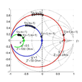
도 14는 본 발명의 또 다른 실시예에 따른 부하 및 임피던스 매칭 네트워크의 임피던스(Z') 변화를 스미스 챠트에 표시한 그림이다.14 is a diagram showing a change in impedance (Z') of a load and impedance matching network according to another embodiment of the present invention on a Smith chart.
도 15는 도 14의 스미스 차트에 표시된 서셉턴스를 구동 주파수에 따라 표시한 그래프이다.15 is a graph showing the susceptance displayed in the Smith chart of FIG. 14 according to the driving frequency.
도 14 및 도 15을 참조하면, g'=1인 컨덕턴스 서클은 임피던스(Z')의 실수부(Re(Z'))가 50 오옴인 경우이다. g'=0.5인 서클은 임피던스의 실수부(Re(Z'))가 100 오옴인 경우이다. g'=2인 서클은 임피던스의 실수부(Re(Z'))가 25 오옴인 경우이다. 14 and 15, the conductance circle of g'=1 is a case where the real part (Re(Z')) of the
임피던스의 실수부(Re(Z'))가 50 오옴이 아닌 경우에도, 펄스형 가변 주파수 RF 발생기는 동작할 수 있다. 즉, 임피던스 매칭은 수행되지 않지만, 반사계수의 절대값(|Γ'|)을 최소화시키는 구동 주파수가 존재한다. g'=0.5인 서클에서, K 위치는 반사계수의 허수부(Im(Γ'))가 영이 되는 지점으로, 임피던스 매칭 조건 대신에 최적 주파수 위치로 사용될 수 있다. g'=2인 서클에서, L 위치는 반사계수의 허수부(Im(Γ'))가 영이 되는 지점으로, 임피던스 매칭 조건 대신에 최적 주파수 위치로 사용될 수 있다.Even when the real part of the impedance (Re(Z')) is not 50 ohms, the pulsed variable frequency RF generator can operate. That is, impedance matching is not performed, but there is a driving frequency that minimizes the absolute value of the reflection coefficient (|Γ'|). In a circle where g'=0.5, the K position is a point at which the imaginary part (Im(Γ') of the reflection coefficient becomes zero), and may be used as an optimum frequency position instead of an impedance matching condition. In a circle where g'=2, the L position is a point at which the imaginary part Im(Γ') of the reflection coefficient becomes zero, and may be used as an optimal frequency position instead of an impedance matching condition.
다시 도 7을 참조하면, S124 단계에서, 상기 위상 이동된 반사계수(Γ')를 이용하여 임피던스 매칭을 위한 최적 조건을 판단할 수 있다. 상기 최적 조건은 상기 위상 이동된 반사계수의 절대값(|Γ'|) 또는 상기 위상 이동된 반사계수(Γ')의 허수부(Im(Γ'))의 크기로 판단한다. 예를 들어, 상기 위상 이동된 반사계수(Γ')의 허수부(Im(Γ'))의 절대값이 문턱값 이하인 경우 최적 조건을 판단한다. 임피던스의 매칭은 반사계수의 절대값(|Γ'|)으로 판단될 수 있으나, 임피던스 매칭이 수행되지 않은 경우에는, 반사계수의 허수부(Im(Γ'))가 영인지 여부 (또는 임계값이하 인지 여부)로 최적 조건을 판단할 수 있다.Referring back to FIG. 7, in step S124, an optimum condition for impedance matching may be determined using the phase-shifted reflection coefficient Γ'. The optimum condition is determined by the magnitude of the absolute value of the phase-shifted reflection coefficient (|Γ'|) or the imaginary part (Im(Γ')) of the phase-shifted reflection coefficient (Γ'). For example, when the absolute value of the imaginary part Im(Γ') of the phase-shifted reflection coefficient Γ'is less than or equal to the threshold value, the optimum condition is determined. The impedance matching can be determined as the absolute value of the reflection coefficient (|Γ'|), but if impedance matching is not performed, whether the imaginary part of the reflection coefficient (Im(Γ')) is zero (or threshold Or not) to determine the optimal condition.
따라서, 반사계수의 허수부(Im(Γ'))가 영인 경우, 현재 상황에서 최적 구동 주파수이다. 따라서, 구동 주파수는 최적 구동 주파수로 유지될 수 있다.Therefore, when the imaginary part Im(Γ') of the reflection coefficient is zero, it is the optimum driving frequency in the current situation. Thus, the driving frequency can be maintained at the optimum driving frequency.
한편, 임피던스의 실수부가 50 오옴보다 큰 값을 가지는 경우 예측 구동 주파수의 오차는 증가할 수 있다. 하지만, 이 오차는 하나의 펄스 내에서 제어 루프 알고리즘에 의하여 도달할 수 있다. n+1번째 펄스에서도 f_match에 이르지 못할 경우에, 구동 주파수를 예측하는 알고리즘이 매 펄스마다 수행되어, n+2번째 펄스내에서 최적의 구동 주파수에 도달한다.Meanwhile, when the real part of the impedance has a value greater than 50 ohms, the error of the predicted driving frequency may increase. However, this error can be reached by the control loop algorithm within one pulse. When f_match is not reached even in the n+1th pulse, an algorithm for predicting the driving frequency is performed every pulse, and the optimum driving frequency is reached within the n+2th pulse.
상기 펄스형 가변 주파수 RF 발생기는 구동 주파수를 변경하여 최적 구동 주파수에서 동작할 수 있다. 임피던스 매칭 네트워크(130)는 상기 펄스형 가변 주파수 RF 발생기(110)와 상기 부하(140) 사이에 배치되고 적어도 2 개의 가변 리액턴스 소자를 포함한다. 상기 임피던스 매칭 네트워크(130)는 완벽한 임피던스 매칭을 위하여 가변 리액턴스 소자의 리액턴스 값을 변경한다. 이에 따라, 임피던스 매칭 네트워크의 입력단(N2)에서 상기 부하 방향의 상기 임피던스의 실수부(Re(Z'))는 전송선의 특성 임피던스(Z0)로 변경될 수 있다. 이에 따라, g'=1인 컨덕턴스 서클 상에 임피던스(Z')가 존재하여, 상기 펄스형 가변 주파수 RF 발생기는 임피던스 매칭을 수행할 수 있다.The pulsed variable frequency RF generator can operate at an optimum driving frequency by changing a driving frequency. The
도 16은 본 발명의 또 다른 실시예에 따른 펄스 시퀀스를 나타내는 도면이다.16 is a diagram showing a pulse sequence according to another embodiment of the present invention.
도 16을 참조하면, 본 발명의 구동 주파수를 예측하는 알고리즘이 수행되기 전에, 적어도 하나의 구동 주파수를 예측하는 알고리즘이 수행되지 않는 펄스가 부하에 전달될 수 있다. 이러한 펄스는 플라즈마를 초기 방전하여 안정화시킬 수 있다. 플라즈마 안정화 구간 동안, 구동 주파수는 이미 설정된 시작 구동 주파수(f_start)로 동작할 수 있다. 상기 펄스형 가변 주파수 RF 발생기의 구동 주파수를 변경하지 않으면서 교번하는 온타임 구간(T_ON)과 오프 타임 구간(T_OFF)을 포함하는 플라즈마 안정화시키는 단계를 포함할 수 있다. Referring to FIG. 16, before the algorithm for predicting the driving frequency of the present invention is performed, a pulse for which the algorithm for predicting at least one driving frequency is not performed may be transmitted to the load. This pulse can be stabilized by initial discharge of the plasma. During the plasma stabilization period, the driving frequency may operate at a previously set start driving frequency f_start. Plasma stabilization including alternating on-time periods T_ON and off-time periods T_OFF without changing the driving frequency of the pulsed variable frequency RF generator may be included.
이상에서는 본 발명을 특정의 바람직한 실시예에 대하여 도시하고 설명하였으나, 본 발명은 이러한 실시예에 한정되지 않으며, 당해 발명이 속하는 기술분야에서 통상의 지식을 가진 자가 특허청구범위에서 청구하는 본 발명의 기술적 사상을 벗어나지 않는 범위 내에서 실시할 수 있는 다양한 형태의 실시예들을 모두 포함한다.In the above, the present invention has been illustrated and described with respect to specific preferred embodiments, but the present invention is not limited to these embodiments, and the present invention claimed in the claims by a person of ordinary skill in the technical field to which the present invention pertains. It includes all various types of embodiments that can be implemented without departing from the technical idea.
100: 펄스형 가변 주파수 RF 전원 시스템
110: 펄스형 가변 주파수 RF 발생기
120: 전송선
130: 임피던스 매칭 네트워크
140: 부하100: Pulsed variable frequency RF power system
110: pulsed variable frequency RF generator
120: transmission line
130: impedance matching network
140: load
Claims (12)
n 번째 펄스의 온타임 구간(T_ON(n))에서 구동 주파수(f(n,m))를 변경하는 단계;
상기 n 번째 펄스의 온타임 구간(T_ON(n))의 어드미턴스를 이용하여 n+1 번째 펄스의 온타임 구간(T_ON(n+1))의 구동 주파수를 예측하는 단계; 및
n+1 번째 펄스의 온타임(T_ON(n+1))에서 상기 예측된 구동 주파수(f(n+1,1))로 상기 펄스형 가변 주파수 RF 발생기의 RF 출력을 제공하는 단계를 포함하고,
여기서,
f(n,m)은 n 번째 펄스의 온타임 구간(T_ON(n)) 내에서 m 번째 처리 회수에서 구동 주파수이고,
n은 펄스의 순번을 나타내고,
m은 1 내지 q 사이의 양의 정수이고,
m은 온타임 구간(T_ON) 내에서 구동 주파수의 변경을 위한 상기 제어 루프의 처리 회수를 나타내는 인덱스를 나타내는 것을 특징으로 하는 펄스형 가변 주파수 RF 발생기의 구동 주파수 제어 방법.Pulsed variable frequency RF including a control loop that provides RF power to the load with pulses of alternating on-time period (T_ON) and off-time period (T_OFF), and changes the driving frequency within the on-time period (T_ON) In the generator impedance matching method,
changing the driving frequency f(n,m) in the on-time period T_ON(n) of the nth pulse;
Predicting a driving frequency of the on-time period (T_ON(n+1)) of the n+1th pulse by using the admittance of the on-time period (T_ON(n)) of the n-th pulse; And
Providing an RF output of the pulsed variable frequency RF generator at the predicted driving frequency (f(n+1,1)) at the on time of the n+1th pulse (T_ON(n+1)), ,
here,
f(n,m) is the driving frequency at the m-th processing number within the on-time period (T_ON(n)) of the n-th pulse,
n represents the sequence number of the pulse,
m is a positive integer between 1 and q,
m denotes an index indicating the number of times the control loop is processed for changing the driving frequency within the on-time period (T_ON). The method of controlling a driving frequency of a pulsed variable frequency RF generator, characterized in that.
n 번째 펄스의 온타임 구간(T_ON(n))에서 구동 주파수(f(n,m))를 변경하는 단계는:
n 번째 펄스의 온타임 구간(T_ON(n))에서 상기 펄스형 가변 주파수 RF 발생기의 출력단에서 RF 전류 신호(I) 및 RF 전압 신호(V)를 측정하는 제1 단계;
n 번째 펄스의 온타임 구간(T_ON(n))에서에서 상기 RF 전류 신호(I) 및 상기 RF 전압 신호(V)를 이용하여 상기 펄스형 가변 주파수 RF 발생기의 출력단에서 임피던스(Zi), 반사계수(Γi), 및 전송선에 의한 위상을 반영한 위상 이동된 반사계수(Γ'), 위상 이동된 어드미턴스(y')를 산출하는 제2 단계; 및
n 번째 펄스의 온타임 구간(T_ON(n))에서 상기 위상 이동된 반사 계수의 허수부(Im(Γ'))의 부호에 따라 상기 펄스형 가변 주파수 RF 발생기의 구동 주파수의 증감 방향을 선택하여 상기 구동 주파수를 변경하는 제3 단계;를 포함하고,
n 번째 펄스의 온타임 구간(T_ON(n))이 종료시 까지 상기 제1 단계, 상기 제2 단계, 및 상기 제3 단계는 반복되는 것을 특징으로 하는 펄스형 가변 주파수 RF 발생기의 구동 주파수 제어 방법.The method of claim 1,
The step of changing the driving frequency (f(n,m)) in the on-time period (T_ON(n)) of the nth pulse is:
a first step of measuring the RF current signal (I) and the RF voltage signal (V) at the output terminal of the pulsed variable frequency RF generator in the on-time period (T_ON(n)) of the nth pulse;
Impedance (Zi) and reflection coefficient at the output terminal of the pulse-type variable frequency RF generator using the RF current signal (I) and the RF voltage signal (V) in the on-time period of the nth pulse (T_ON(n)) A second step of calculating (Γi), a phase-shifted reflection coefficient (Γ') and a phase-shifted admittance (y') reflecting the phase of the transmission line; And
In the on-time period of the nth pulse (T_ON(n)), according to the sign of the imaginary part (Im(Γ')) of the phase-shifted reflection coefficient, an increase or decrease direction of the driving frequency of the pulsed variable frequency RF generator is selected. Including a third step of changing the driving frequency;
The first step, the second step, and the third step are repeated until the on-time period (T_ON(n)) of the n-th pulse is terminated. A method of controlling a driving frequency of a pulsed variable frequency RF generator.
상기 n 번째 펄스의 온타임 구간(T_ON(n))의 어드미턴스를 이용하여 n+1 번째 펄스의 온타임 구간(T_ON(n+1))의 구동 주파수를 예측하는 단계는:
n 번째 온타임 구간(T_ON(n))에서 위상 이동된 어드미턴스(y')의 허수부를 구동 주파수에 따라 직선 피팅하는 단계; 및
상기 위상 이동된 어드미턴스(y')의 허수부가 영인 지점에 대응하는 주파수를 n+1 번째 펄스의 온타임 구간(T_ON(n+1))의 예측된 구동 주파수(f(n+1,1))로 설정하는 단계를 포함하는 것을 특징으로 하는 펄스형 가변 주파수 RF 발생기의 구동 주파수 제어 방법.The method of claim 2,
Predicting the driving frequency of the on-time period T_ON(n+1) of the n+1th pulse using the admittance of the on-time period T_ON(n) of the nth pulse:
linearly fitting the imaginary part of the admittance (y') phase-shifted in the n-th on-time period (T_ON(n)) according to the driving frequency; And
The frequency corresponding to the point where the imaginary part of the phase-shifted admittance (y') is zero is the predicted driving frequency (f(n+1,1) of the on-time period (T_ON(n+1)) of the n+1th pulse) ), the driving frequency control method of a pulsed variable frequency RF generator, comprising the step of setting.
상기 n+1 번째 펄스의 온타임 구간(T_ON(n+1))의 상기 예측 구동 주파수(f(n+1,m=1))는
f(n+1,m=1) = f(n,m=r) - b'(n,m=r) [df(n,m=r)/db'(n,m=r)]
df(n,m=r)/db'(n,m=r)= [f(n,m=q)-f(n,m=r)]/[b'(n,m=q)-b'(n,m=r)])
으로 주어지고,
여기서,
f(n,m=r)는 n 번째 펄스의 온타임 구간(T_ON(n))에서 소정의 r 번째 처리 회수에서 구동 주파수이고,
b'(n,m=r)은 n 번째 펄스의 온타임 구간(T_ON(n))의 소정의 r 번째 처리 회수에서 상기 위상 이동된 어드미턴스(y')의 허수부인 서셉턴스이고,
f(n,m=q)는 n 번째 펄스의 온타임 구간(T_ON(n))에서 마지막 처리 회수에서 구동 주파수이고,
b'(n,m=q)은 n 번째 펄스의 온타임 구간(T_ON(n))의 마지막 처리 회수의 어드미턴스(y')의 허수부인 서셉턴스인 것을 특징으로 하는 펄스형 가변 주파수 RF 발생기의 구동 주파수 제어 방법.The method of claim 3,
The predicted driving frequency (f(n+1,m=1)) of the on-time period (T_ON(n+1)) of the n+1th pulse is
f(n+1,m=1) = f(n,m=r)-b'(n,m=r) [df(n,m=r)/db'(n,m=r)]
df(n,m=r)/db'(n,m=r)= [f(n,m=q)-f(n,m=r)]/[b'(n,m=q)- b'(n,m=r)])
Given by,
here,
f(n,m=r) is the driving frequency at a predetermined r-th processing number in the on-time period of the n-th pulse (T_ON(n)),
b'(n,m=r) is the susceptance, which is the imaginary part of the admittance y', which has been phase-shifted at a predetermined r-th processing number of the on-time period T_ON(n) of the nth pulse,
f(n,m=q) is the driving frequency at the last number of processing times in the on-time period (T_ON(n)) of the nth pulse,
b'(n,m=q) is the susceptance, which is the imaginary part of the admittance (y') of the last number of processing times of the on-time period of the nth pulse (T_ON(n)), of a pulse type variable frequency RF generator. Driving frequency control method.
r은 3 내지 q-1의 양의 정수인 것을 특징으로 하는 펄스형 가변 주파수 RF 발생기의 구동 주파수 제어 방법.The method of claim 4,
r is a positive integer of 3 to q-1, wherein the driving frequency control method of a pulsed variable frequency RF generator.
상기 위상 이동된 반사계수(Γ')를 이용하여 임피던스 매칭을 위한 최적 조건을 판단하는 단계를 더 포함하고,
상기 최적 조건은 상기 위상 이동된 반사계수의 절대값(|Γ'|) 또는 상기 위상 이동된 반사계수(Γ')의 허수부(Im(Γ'))의 크기로 판단하고,
상기 최적 조건인 경우, 구동 주파수의 변경을 위한 처리 회수를 나타내는 인덱스(m)을 증가시킨 후 상기 펄스형 가변 주파수 RF 발생기의 출력단에서 RF 전류 신호(I) 및 RF 전압 신호(V)를 측정하는 제1 단계를 수행하고,
상기 최적 조건이 아닌 경우, 상기 구동 주파수를 변경하는 제3 단계를 수행하는 것을 특징으로 하는 펄스형 가변 주파수 RF 발생기의 구동 주파수 제어 방법.The method of claim 2,
Further comprising the step of determining an optimum condition for impedance matching using the phase-shifted reflection coefficient (Γ'),
The optimal condition is determined by the magnitude of the absolute value of the phase-shifted reflection coefficient (|Γ'|) or the imaginary part (Im(Γ')) of the phase-shifted reflection coefficient (Γ'),
In the case of the optimal condition, after increasing the index (m) representing the number of times of processing for changing the driving frequency, the RF current signal (I) and the RF voltage signal (V) are measured at the output terminal of the pulsed variable frequency RF generator. Perform the first step,
If the optimum condition is not, the driving frequency control method of the pulse type variable frequency RF generator, characterized in that performing a third step of changing the driving frequency.
n 번째 온타임 구간(T_ON(n))에서 상기 위상 이동된 반사 계수의 허수부(Im(Γ'))의 부호에 따라 상기 펄스형 가변 주파수 RF 발생기의 구동 주파수의 증감 방향을 선택하고 상기 구동 주파수를 변경하는 제3 단계는,
상기 위상 이동된 반사 계수의 허수부(Im(Γ'))가 양의 값을 가지는 경우 구동 주파수를 증가시키고,
상기 위상 이동된 반사 계수의 허수부(Im(Γ'))가 음의 값을 가지는 경우 구동 주파수를 감소시키는 것을 특징으로 하는 펄스형 가변 주파수 RF 발생기의 구동 주파수 제어 방법.The method of claim 2,
In the n-th on-time period (T_ON(n)), according to the sign of the imaginary part (Im(Γ')) of the phase-shifted reflection coefficient, a direction of increase or decrease of the driving frequency of the pulsed variable frequency RF generator is selected, and the driving The third step of changing the frequency,
When the imaginary part (Im(Γ')) of the phase-shifted reflection coefficient has a positive value, the driving frequency is increased,
When the imaginary part (Im(Γ')) of the phase-shifted reflection coefficient has a negative value, the driving frequency is reduced.
n 번째 온타임 구간(T_ON(n)) 내에서 상기 구동 주파수의 변화량은 상기 위상 이동된 반사 계수의 절대값 또는 상기 위상 이동된 반사 계수의 허수부의 절대값에 의존하는 것을 특징으로 하는 펄스형 가변 주파수 RF 발생기의 구동 주파수 제어 방법.The method of claim 7,
Pulsed variable, characterized in that the amount of change in the driving frequency within the n-th on-time period (T_ON(n)) depends on the absolute value of the phase-shifted reflection coefficient or the absolute value of the imaginary part of the phase-shifted reflection coefficient. Frequency RF generator driving frequency control method.
상기 펄스형 가변 주파수 RF 발생기와 상기 부하 사이에 배치되고 적어도 2 개의 가변 리액턴스 소자를 포함하는 임피던스 매칭 네트워크의 가변 리액턴스 소자의 리액턴스값을 변경하여 상기 펄스형 가변 주파수 RF 발생기의 출력단에서 상기 부하 방향의 상기 임피던스의 실수부(Re(Zi))를 전송선의 특성 임피던스로 설정하는 단계를 더 포함하는 것을 특징으로 하는 펄스형 가변 주파수 RF 발생기의 구동 주파수 제어 방법.The method of claim 1,
By changing the reactance value of the variable reactance element of the impedance matching network disposed between the pulsed variable frequency RF generator and the load and including at least two variable reactance elements, the output terminal of the pulsed variable frequency RF generator in the load direction And setting the real part (Re(Zi)) of the impedance as the characteristic impedance of the transmission line.
상기 펄스형 가변 주파수 RF 발생기의 구동 주파수를 변경하지 않으면서 교번하는 온타임 구간(T_ON)과 오프 타임 구간(T_OFF)을 포함하는 플라즈마 안정화시키는 단계를 더 포함하는 것을 특징으로 하는 펄스형 가변 주파수 RF 발생기의 구동 주파수 제어 방법.The method of claim 1,
Pulsed variable frequency RF, characterized in that it further comprises the step of plasma stabilizing including alternating on-time periods (T_ON) and off-time periods (T_OFF) without changing the driving frequency of the pulsed variable frequency RF generator. How to control the driving frequency of the generator.
상기 펄스형 가변 주파수 RF 발생기는:
n 번째 온타임 구간(T_ON(n))에서 상기 펄스형 가변 주파수 RF 발생기의 출력단에 배치되어 RF 전류 신호 및 RF 전압 신호를 감지하는 임피던스 감지부;
n 번째 온타임 구간(T_ON(n))에서 상기 RF 전류 신호 및 상기 RF 전압 신호를 이용하여 상기 펄스형 가변 주파수 RF 발생기의 출력단에서의 임피던스(Zi) 및 반사계수(Γi), 상기 부하와 펄스형 가변 주파수 RF 발생기 사이의 전송선에 의한 위상 이동된 반사계수(Γ'), 그리고 상기 위상 이동된 반사계수(Γ')에서 변환된 위상 이동된 어드미턴스(y')를 산출하는 임피던스 처리부;
구동 주파수에 따른 상기 위상 이동된 어드미턴스(y')를 이용하여 다음 온타임 구간(T_ON(n+1))의 구동 주파수를 예측하는 구동 주파수 예측부;
상기 예측된 구동 주파수를 제공받아 다음 온타임 구간(T_ON(n+1))의 시작 구동 주파수로 설정하고 상기 위상 이동된 반사계수(Γ')를 이용하여 구동 주파수를 제어하는 구동 주파수 제어부;
펄스 신호를 생성하여 온타임 구간(T_ON)과 오프 타임 구간(T_OFF)을 구분하고 상기 펄스 신호를 상기 구동 주파수 예측부 및 상기 구동 주파수 제어부에 제공하는 펄스 발생기; 및
상기 구동 주파수 제어부의 구동 주파수의 정현파를 증폭시키는 RF 증폭기를 포함하는 것을 특징으로 하는 펄스형 가변 주파수 RF 전원 시스템.In the pulsed variable frequency RF power supply device comprising a pulsed variable frequency RF generator for providing RF power to a load in an alternating on-time period (T_ON) and off-time period (T_OFF),
The pulsed variable frequency RF generator is:
an impedance sensing unit disposed at the output terminal of the pulsed variable frequency RF generator in the n-th on-time period T_ON(n) to detect an RF current signal and an RF voltage signal;
Impedance (Zi) and reflection coefficient (Γi) at the output terminal of the pulsed variable frequency RF generator using the RF current signal and the RF voltage signal in the n-th on-time period (T_ON(n)), and the load and pulse An impedance processing unit that calculates a phase shifted reflection coefficient (Γ') by a transmission line between the variable frequency RF generator and a phase shifted admittance (y') converted from the phase shifted reflection coefficient (Γ');
A driving frequency prediction unit predicting a driving frequency of the next on-time period T_ON(n+1) using the phase-shifted admittance (y') according to the driving frequency;
A driving frequency controller configured to receive the predicted driving frequency, set it as a starting driving frequency of the next on-time period (T_ON(n+1)), and control a driving frequency using the phase-shifted reflection coefficient Γ';
A pulse generator that generates a pulse signal to divide an on-time period (T_ON) and an off-time period (T_OFF), and provides the pulse signal to the driving frequency prediction unit and the driving frequency controller; And
And an RF amplifier for amplifying a sine wave of a driving frequency of the driving frequency controller.
상기 구동 주파수 예측부는 n 번째 온타임 구간(T_ON(n))에서 구동 주파수에 따른 위상 이동된 어드미턴스(y')의 허수부를 직선 피팅하여 위상 이동된 어드미턴스(y')의 허수부가 영인 지점에 대응하는 주파수를 예측 구동 주파수로 설정하는 것을 특징으로 하는 펄스형 가변 주파수 RF 전원 시스템.The method of claim 11,
The driving frequency prediction unit corresponds to a point where the imaginary part of the phase-shifted admittance (y') is zero by linearly fitting the imaginary part of the admittance (y') phase-shifted according to the driving frequency in the n-th on-time period (T_ON(n)). A pulsed variable frequency RF power supply system, characterized in that setting the frequency to be a predicted driving frequency.
Priority Applications (8)
| Application Number | Priority Date | Filing Date | Title |
|---|---|---|---|
| KR1020190014594A KR102348338B1 (en) | 2019-02-07 | 2019-02-07 | The Driving Frequency Control Method of The Pulsed Frequency Variable RF Generator |
| CN201980001598.7A CN111801766B (en) | 2019-02-07 | 2019-06-27 | Method for controlling driving frequency of pulse type variable frequency RF generator |
| JP2019547117A JP7104057B2 (en) | 2019-02-07 | 2019-06-27 | Drive frequency control method for pulse-type variable frequency RF generator |
| US16/484,062 US11244809B2 (en) | 2019-02-07 | 2019-06-27 | Control method of driving frequency of pulsed variable frequency RF generator |
| PCT/KR2019/007802 WO2020162653A1 (en) | 2019-02-07 | 2019-06-27 | Method for controlling driving frequency of pulsed variable frequency rf generator |
| SG11201908001VA SG11201908001VA (en) | 2019-02-07 | 2019-06-27 | Control method of driving frequency of pulsed variable frequency rf generator |
| EP19191658.4A EP3694104B1 (en) | 2019-02-07 | 2019-08-14 | Control method of driving frequency of pulsed variable frequency rf generator |
| TW108131286A TWI713416B (en) | 2019-02-07 | 2019-08-30 | Control method of driving frequency of pulsed variable frequency rf generator |
Applications Claiming Priority (1)
| Application Number | Priority Date | Filing Date | Title |
|---|---|---|---|
| KR1020190014594A KR102348338B1 (en) | 2019-02-07 | 2019-02-07 | The Driving Frequency Control Method of The Pulsed Frequency Variable RF Generator |
Publications (2)
| Publication Number | Publication Date |
|---|---|
| KR20200097161A true KR20200097161A (en) | 2020-08-18 |
| KR102348338B1 KR102348338B1 (en) | 2022-01-06 |
Family
ID=71947882
Family Applications (1)
| Application Number | Title | Priority Date | Filing Date |
|---|---|---|---|
| KR1020190014594A KR102348338B1 (en) | 2019-02-07 | 2019-02-07 | The Driving Frequency Control Method of The Pulsed Frequency Variable RF Generator |
Country Status (8)
| Country | Link |
|---|---|
| US (1) | US11244809B2 (en) |
| EP (1) | EP3694104B1 (en) |
| JP (1) | JP7104057B2 (en) |
| KR (1) | KR102348338B1 (en) |
| CN (1) | CN111801766B (en) |
| SG (1) | SG11201908001VA (en) |
| TW (1) | TWI713416B (en) |
| WO (1) | WO2020162653A1 (en) |
Cited By (2)
| Publication number | Priority date | Publication date | Assignee | Title |
|---|---|---|---|---|
| WO2023064012A1 (en) * | 2021-10-15 | 2023-04-20 | Mks Instruments, Inc. | Impedance matching in a rf power generation system |
| WO2023215073A1 (en) * | 2022-05-05 | 2023-11-09 | Applied Materials, Inc. | Control and prediction of multiple plasma coupling surfaces and corresponding power transfer |
Citations (1)
| Publication number | Priority date | Publication date | Assignee | Title |
|---|---|---|---|---|
| KR20100125376A (en) * | 2008-03-23 | 2010-11-30 | 어드밴스드 에너지 인더스트리즈 인코포레이티드 | Method and apparatus for advanced frequency tuning |
Family Cites Families (24)
| Publication number | Priority date | Publication date | Assignee | Title |
|---|---|---|---|---|
| US6259615B1 (en) * | 1999-07-22 | 2001-07-10 | O2 Micro International Limited | High-efficiency adaptive DC/AC converter |
| US6804129B2 (en) * | 1999-07-22 | 2004-10-12 | 02 Micro International Limited | High-efficiency adaptive DC/AC converter |
| US20080179948A1 (en) * | 2005-10-31 | 2008-07-31 | Mks Instruments, Inc. | Radio frequency power delivery system |
| US7764140B2 (en) * | 2005-10-31 | 2010-07-27 | Mks Instruments, Inc. | Radio frequency power delivery system |
| KR20080072642A (en) | 2005-10-31 | 2008-08-06 | 엠케이에스 인스트루먼츠, 인코포레이티드 | Radio frequency power delivery system |
| KR100895689B1 (en) | 2007-11-14 | 2009-04-30 | 주식회사 플라즈마트 | Impedance matching methods and electric apparatus performing the same |
| KR20120022251A (en) * | 2010-09-01 | 2012-03-12 | 삼성전자주식회사 | Plasma etching method and apparatus thereof |
| JP5576819B2 (en) * | 2011-03-23 | 2014-08-20 | パナソニック株式会社 | Lighting device and lighting apparatus |
| JP5867701B2 (en) * | 2011-12-15 | 2016-02-24 | 東京エレクトロン株式会社 | Plasma processing equipment |
| US8576013B2 (en) * | 2011-12-29 | 2013-11-05 | Mks Instruments, Inc. | Power distortion-based servo control systems for frequency tuning RF power sources |
| CN104350679B (en) | 2012-06-01 | 2017-03-22 | 诺森有限公司 | Impedance matching device and method |
| KR20140058787A (en) | 2012-11-06 | 2014-05-15 | 세메스 주식회사 | Apparatus for generating plasma and method for matching impedance thereof |
| US9294100B2 (en) | 2012-12-04 | 2016-03-22 | Advanced Energy Industries, Inc. | Frequency tuning system and method for finding a global optimum |
| KR101544975B1 (en) | 2013-09-30 | 2015-08-18 | 주식회사 플라즈마트 | Impedance Matching Method And Impedance Matching System |
| CN103632927B (en) * | 2013-12-19 | 2016-03-16 | 中微半导体设备(上海)有限公司 | The impedance matching methods of plasma etching system |
| US9520795B2 (en) * | 2014-01-08 | 2016-12-13 | Semiconductor Components Industries, Llc | Method of forming a power supply controller and structure therefor |
| US9336901B2 (en) | 2014-03-17 | 2016-05-10 | Lam Research Corporation | Track and hold feedback control of pulsed RF |
| US9544987B2 (en) * | 2014-06-30 | 2017-01-10 | Advanced Energy Industries, Inc. | Frequency tuning for pulsed radio frequency plasma processing |
| KR101677748B1 (en) * | 2014-10-29 | 2016-11-29 | 삼성전자 주식회사 | Pulse plasma apparatus and method for operating the same |
| CN105826154B (en) * | 2015-01-06 | 2017-12-19 | 北京北方华创微电子装备有限公司 | For the impedance matching methods and device of pulse radiation frequency power supply |
| KR101983873B1 (en) | 2015-03-24 | 2019-05-29 | 엠케이에스코리아 유한회사 | Impedance Matching Method And Impedance Matching System |
| US9876476B2 (en) | 2015-08-18 | 2018-01-23 | Mks Instruments, Inc. | Supervisory control of radio frequency (RF) impedance tuning operation |
| US10483854B2 (en) * | 2017-05-19 | 2019-11-19 | Semiconductor Components Industries, Llc | Resonant power supply converter circuit and method therefor |
| CN109148250B (en) * | 2017-06-15 | 2020-07-17 | 北京北方华创微电子装备有限公司 | Impedance matching device and impedance matching method |
-
2019
- 2019-02-07 KR KR1020190014594A patent/KR102348338B1/en active IP Right Grant
- 2019-06-27 US US16/484,062 patent/US11244809B2/en active Active
- 2019-06-27 SG SG11201908001VA patent/SG11201908001VA/en unknown
- 2019-06-27 CN CN201980001598.7A patent/CN111801766B/en active Active
- 2019-06-27 JP JP2019547117A patent/JP7104057B2/en active Active
- 2019-06-27 WO PCT/KR2019/007802 patent/WO2020162653A1/en active Application Filing
- 2019-08-14 EP EP19191658.4A patent/EP3694104B1/en active Active
- 2019-08-30 TW TW108131286A patent/TWI713416B/en active
Patent Citations (1)
| Publication number | Priority date | Publication date | Assignee | Title |
|---|---|---|---|---|
| KR20100125376A (en) * | 2008-03-23 | 2010-11-30 | 어드밴스드 에너지 인더스트리즈 인코포레이티드 | Method and apparatus for advanced frequency tuning |
Cited By (3)
| Publication number | Priority date | Publication date | Assignee | Title |
|---|---|---|---|---|
| WO2023064012A1 (en) * | 2021-10-15 | 2023-04-20 | Mks Instruments, Inc. | Impedance matching in a rf power generation system |
| US11823869B2 (en) | 2021-10-15 | 2023-11-21 | Mks Instruments, Inc. | Impedance matching in a RF power generation system |
| WO2023215073A1 (en) * | 2022-05-05 | 2023-11-09 | Applied Materials, Inc. | Control and prediction of multiple plasma coupling surfaces and corresponding power transfer |
Also Published As
| Publication number | Publication date |
|---|---|
| SG11201908001VA (en) | 2020-09-29 |
| CN111801766B (en) | 2023-08-25 |
| EP3694104A1 (en) | 2020-08-12 |
| EP3694104B1 (en) | 2023-10-11 |
| TWI713416B (en) | 2020-12-11 |
| JP7104057B2 (en) | 2022-07-20 |
| US11244809B2 (en) | 2022-02-08 |
| US20210335576A1 (en) | 2021-10-28 |
| JP2021516412A (en) | 2021-07-01 |
| TW202031098A (en) | 2020-08-16 |
| CN111801766A (en) | 2020-10-20 |
| KR102348338B1 (en) | 2022-01-06 |
| WO2020162653A1 (en) | 2020-08-13 |
Similar Documents
| Publication | Publication Date | Title |
|---|---|---|
| JP6512962B2 (en) | Plasma processing system | |
| EP2642661B1 (en) | System and methods of bimodal automatic power and frequency tuning of RF generators | |
| US10115567B2 (en) | Plasma processing apparatus | |
| US5543689A (en) | High frequency power source having corrected power output | |
| KR102265231B1 (en) | Plasma processing apparatus | |
| US7967944B2 (en) | Method of plasma load impedance tuning by modulation of an unmatched low power RF generator | |
| US8018164B2 (en) | Plasma reactor with high speed plasma load impedance tuning by modulation of different unmatched frequency sources | |
| US5474648A (en) | Uniform and repeatable plasma processing | |
| JP5117540B2 (en) | High frequency equipment | |
| TW202107515A (en) | A radio frequency generator of high speed synchronization of plasma source/bias power delivery and generating method thereof | |
| US20090297404A1 (en) | Plasma reactor with high speed plasma impedance tuning by modulation of source power or bias power | |
| TW201112887A (en) | Inductively coupled plasma reactor having RF phase control and methods of use thereof | |
| KR102348338B1 (en) | The Driving Frequency Control Method of The Pulsed Frequency Variable RF Generator | |
| JPWO2004010746A1 (en) | Plasma processing apparatus and control method thereof | |
| WO2022010686A1 (en) | Systems and methods for extracting process control information from radiofrequency supply system of plasma processing system | |
| US10410834B1 (en) | Reverse power reducing method and plasma power apparatus using the same | |
| US20090294275A1 (en) | Method of plasma load impedance tuning by modulation of a source power or bias power rf generator | |
| KR20190048234A (en) | Impedance Matching Method of RF Power | |
| KR20240008318A (en) | System and method for real-time pulse measurement and pulse timing adjustment to control plasma process performance | |
| JPH11172436A (en) | High-frequency power source device for deposition apparatus, position regulator and discharge state fluctuation rate monitor | |
| US20230253185A1 (en) | Systems and Methods for Radiofrequency Signal Generator-Based Control of Impedance Matching System | |
| EP4038656B1 (en) | Determining an optimal ion energy for plasma processing of a dielectric substrate | |
| WO2023176534A1 (en) | Plasma processing device, analysis device, and analysis program | |
| US20220356559A1 (en) | Waveform shape factor for pulsed pvd power | |
| KR102240306B1 (en) | A device for matching the impedance of the plasma apparatus and the method thereof |
Legal Events
| Date | Code | Title | Description |
|---|---|---|---|
| E902 | Notification of reason for refusal | ||
| E701 | Decision to grant or registration of patent right | ||
| GRNT | Written decision to grant |