KR20200095896A - Electrode assembly manufacturing method, and electrode assembly and rechargeable battery manufactured from thereof - Google Patents
Electrode assembly manufacturing method, and electrode assembly and rechargeable battery manufactured from thereof Download PDFInfo
- Publication number
- KR20200095896A KR20200095896A KR1020190013849A KR20190013849A KR20200095896A KR 20200095896 A KR20200095896 A KR 20200095896A KR 1020190013849 A KR1020190013849 A KR 1020190013849A KR 20190013849 A KR20190013849 A KR 20190013849A KR 20200095896 A KR20200095896 A KR 20200095896A
- Authority
- KR
- South Korea
- Prior art keywords
- electrode assembly
- manufacturing
- unit cell
- separator
- electrode
- Prior art date
Links
- 238000004519 manufacturing process Methods 0.000 title claims abstract description 68
- 238000000034 method Methods 0.000 claims abstract description 107
- 238000003475 lamination Methods 0.000 claims abstract description 37
- 238000003825 pressing Methods 0.000 claims abstract description 29
- 238000010438 heat treatment Methods 0.000 claims abstract description 26
- 230000015572 biosynthetic process Effects 0.000 claims description 7
- 238000000926 separation method Methods 0.000 abstract description 8
- 239000012528 membrane Substances 0.000 abstract description 7
- 239000012790 adhesive layer Substances 0.000 description 6
- PXHVJJICTQNCMI-UHFFFAOYSA-N nickel Substances [Ni] PXHVJJICTQNCMI-UHFFFAOYSA-N 0.000 description 5
- 239000007774 positive electrode material Substances 0.000 description 5
- OKTJSMMVPCPJKN-UHFFFAOYSA-N Carbon Chemical compound [C] OKTJSMMVPCPJKN-UHFFFAOYSA-N 0.000 description 4
- 239000000853 adhesive Substances 0.000 description 3
- 230000001070 adhesive effect Effects 0.000 description 3
- 239000007773 negative electrode material Substances 0.000 description 3
- 238000004804 winding Methods 0.000 description 3
- 239000002033 PVDF binder Substances 0.000 description 2
- 230000000712 assembly Effects 0.000 description 2
- 238000000429 assembly Methods 0.000 description 2
- 238000005452 bending Methods 0.000 description 2
- 239000010949 copper Substances 0.000 description 2
- 238000005516 engineering process Methods 0.000 description 2
- 239000011888 foil Substances 0.000 description 2
- 238000012423 maintenance Methods 0.000 description 2
- 230000014759 maintenance of location Effects 0.000 description 2
- 239000000463 material Substances 0.000 description 2
- -1 polyethylene Polymers 0.000 description 2
- 239000005518 polymer electrolyte Substances 0.000 description 2
- 229920002981 polyvinylidene fluoride Polymers 0.000 description 2
- RYGMFSIKBFXOCR-UHFFFAOYSA-N Copper Chemical compound [Cu] RYGMFSIKBFXOCR-UHFFFAOYSA-N 0.000 description 1
- ILNDHDPAQTZMCR-UHFFFAOYSA-N F.[F].[F].[F].[F].[F].[F] Chemical compound F.[F].[F].[F].[F].[F].[F] ILNDHDPAQTZMCR-UHFFFAOYSA-N 0.000 description 1
- 229910000733 Li alloy Inorganic materials 0.000 description 1
- 229910013210 LiNiMnCoO Inorganic materials 0.000 description 1
- 229920003171 Poly (ethylene oxide) Polymers 0.000 description 1
- 239000004698 Polyethylene Substances 0.000 description 1
- 239000004743 Polypropylene Substances 0.000 description 1
- 239000011149 active material Substances 0.000 description 1
- 239000000956 alloy Substances 0.000 description 1
- 229910045601 alloy Inorganic materials 0.000 description 1
- 229910052782 aluminium Inorganic materials 0.000 description 1
- XAGFODPZIPBFFR-UHFFFAOYSA-N aluminium Chemical compound [Al] XAGFODPZIPBFFR-UHFFFAOYSA-N 0.000 description 1
- 229910021383 artificial graphite Inorganic materials 0.000 description 1
- 229910052799 carbon Inorganic materials 0.000 description 1
- 150000001875 compounds Chemical class 0.000 description 1
- 229920001577 copolymer Polymers 0.000 description 1
- 229910052802 copper Inorganic materials 0.000 description 1
- 238000007599 discharging Methods 0.000 description 1
- 229910002804 graphite Inorganic materials 0.000 description 1
- 239000010439 graphite Substances 0.000 description 1
- 239000011810 insulating material Substances 0.000 description 1
- 238000010030 laminating Methods 0.000 description 1
- 239000010410 layer Substances 0.000 description 1
- 229910052744 lithium Inorganic materials 0.000 description 1
- 239000001989 lithium alloy Substances 0.000 description 1
- 229910000625 lithium cobalt oxide Inorganic materials 0.000 description 1
- GELKBWJHTRAYNV-UHFFFAOYSA-K lithium iron phosphate Chemical compound [Li+].[Fe+2].[O-]P([O-])([O-])=O GELKBWJHTRAYNV-UHFFFAOYSA-K 0.000 description 1
- 229910002102 lithium manganese oxide Inorganic materials 0.000 description 1
- BFZPBUKRYWOWDV-UHFFFAOYSA-N lithium;oxido(oxo)cobalt Chemical compound [Li+].[O-][Co]=O BFZPBUKRYWOWDV-UHFFFAOYSA-N 0.000 description 1
- VLXXBCXTUVRROQ-UHFFFAOYSA-N lithium;oxido-oxo-(oxomanganiooxy)manganese Chemical compound [Li+].[O-][Mn](=O)O[Mn]=O VLXXBCXTUVRROQ-UHFFFAOYSA-N 0.000 description 1
- URIIGZKXFBNRAU-UHFFFAOYSA-N lithium;oxonickel Chemical compound [Li].[Ni]=O URIIGZKXFBNRAU-UHFFFAOYSA-N 0.000 description 1
- 239000000203 mixture Substances 0.000 description 1
- 229910052759 nickel Inorganic materials 0.000 description 1
- 239000002006 petroleum coke Substances 0.000 description 1
- 229920002239 polyacrylonitrile Polymers 0.000 description 1
- 229920000573 polyethylene Polymers 0.000 description 1
- 229920006254 polymer film Polymers 0.000 description 1
- 229920001155 polypropylene Polymers 0.000 description 1
- 238000004321 preservation Methods 0.000 description 1
- QQONPFPTGQHPMA-UHFFFAOYSA-N propylene Natural products CC=C QQONPFPTGQHPMA-UHFFFAOYSA-N 0.000 description 1
- 150000003377 silicon compounds Chemical class 0.000 description 1
- 239000007787 solid Substances 0.000 description 1
- 150000003606 tin compounds Chemical class 0.000 description 1
- 150000003609 titanium compounds Chemical class 0.000 description 1
Images


Classifications
-
- H—ELECTRICITY
- H01—ELECTRIC ELEMENTS
- H01M—PROCESSES OR MEANS, e.g. BATTERIES, FOR THE DIRECT CONVERSION OF CHEMICAL ENERGY INTO ELECTRICAL ENERGY
- H01M10/00—Secondary cells; Manufacture thereof
- H01M10/04—Construction or manufacture in general
- H01M10/0459—Cells or batteries with folded separator between plate-like electrodes
-
- H—ELECTRICITY
- H01—ELECTRIC ELEMENTS
- H01M—PROCESSES OR MEANS, e.g. BATTERIES, FOR THE DIRECT CONVERSION OF CHEMICAL ENERGY INTO ELECTRICAL ENERGY
- H01M10/00—Secondary cells; Manufacture thereof
- H01M10/04—Construction or manufacture in general
- H01M10/0468—Compression means for stacks of electrodes and separators
-
- H—ELECTRICITY
- H01—ELECTRIC ELEMENTS
- H01M—PROCESSES OR MEANS, e.g. BATTERIES, FOR THE DIRECT CONVERSION OF CHEMICAL ENERGY INTO ELECTRICAL ENERGY
- H01M10/00—Secondary cells; Manufacture thereof
- H01M10/05—Accumulators with non-aqueous electrolyte
- H01M10/052—Li-accumulators
-
- H—ELECTRICITY
- H01—ELECTRIC ELEMENTS
- H01M—PROCESSES OR MEANS, e.g. BATTERIES, FOR THE DIRECT CONVERSION OF CHEMICAL ENERGY INTO ELECTRICAL ENERGY
- H01M10/00—Secondary cells; Manufacture thereof
- H01M10/05—Accumulators with non-aqueous electrolyte
- H01M10/052—Li-accumulators
- H01M10/0525—Rocking-chair batteries, i.e. batteries with lithium insertion or intercalation in both electrodes; Lithium-ion batteries
-
- H—ELECTRICITY
- H01—ELECTRIC ELEMENTS
- H01M—PROCESSES OR MEANS, e.g. BATTERIES, FOR THE DIRECT CONVERSION OF CHEMICAL ENERGY INTO ELECTRICAL ENERGY
- H01M10/00—Secondary cells; Manufacture thereof
- H01M10/05—Accumulators with non-aqueous electrolyte
- H01M10/058—Construction or manufacture
- H01M10/0583—Construction or manufacture of accumulators with folded construction elements except wound ones, i.e. folded positive or negative electrodes or separators, e.g. with "Z"-shaped electrodes or separators
-
- H—ELECTRICITY
- H01—ELECTRIC ELEMENTS
- H01M—PROCESSES OR MEANS, e.g. BATTERIES, FOR THE DIRECT CONVERSION OF CHEMICAL ENERGY INTO ELECTRICAL ENERGY
- H01M10/00—Secondary cells; Manufacture thereof
- H01M10/60—Heating or cooling; Temperature control
- H01M10/64—Heating or cooling; Temperature control characterised by the shape of the cells
-
- Y—GENERAL TAGGING OF NEW TECHNOLOGICAL DEVELOPMENTS; GENERAL TAGGING OF CROSS-SECTIONAL TECHNOLOGIES SPANNING OVER SEVERAL SECTIONS OF THE IPC; TECHNICAL SUBJECTS COVERED BY FORMER USPC CROSS-REFERENCE ART COLLECTIONS [XRACs] AND DIGESTS
- Y02—TECHNOLOGIES OR APPLICATIONS FOR MITIGATION OR ADAPTATION AGAINST CLIMATE CHANGE
- Y02E—REDUCTION OF GREENHOUSE GAS [GHG] EMISSIONS, RELATED TO ENERGY GENERATION, TRANSMISSION OR DISTRIBUTION
- Y02E60/00—Enabling technologies; Technologies with a potential or indirect contribution to GHG emissions mitigation
- Y02E60/10—Energy storage using batteries
-
- Y—GENERAL TAGGING OF NEW TECHNOLOGICAL DEVELOPMENTS; GENERAL TAGGING OF CROSS-SECTIONAL TECHNOLOGIES SPANNING OVER SEVERAL SECTIONS OF THE IPC; TECHNICAL SUBJECTS COVERED BY FORMER USPC CROSS-REFERENCE ART COLLECTIONS [XRACs] AND DIGESTS
- Y02—TECHNOLOGIES OR APPLICATIONS FOR MITIGATION OR ADAPTATION AGAINST CLIMATE CHANGE
- Y02P—CLIMATE CHANGE MITIGATION TECHNOLOGIES IN THE PRODUCTION OR PROCESSING OF GOODS
- Y02P70/00—Climate change mitigation technologies in the production process for final industrial or consumer products
- Y02P70/50—Manufacturing or production processes characterised by the final manufactured product
Abstract
Description
본 발명은 전극 조립체 제조방법과, 이를 통해 제조된 전극 및 이차전지에 관한 것이다. The present invention relates to a method for manufacturing an electrode assembly, and an electrode and a secondary battery manufactured therefrom.
이차 전지는 일차 전지와는 달리 재충전이 가능하고, 또 소형 및 대용량화 가능성으로 인해 근래에 많이 연구 개발되고 있다. 모바일 기기에 대한 기술 개발과 수요가 증가함에 따라 에너지원으로서의 이차 전지의 수요가 급격하게 증가하고 있다. Unlike a primary battery, a secondary battery is rechargeable and has been researched and developed in recent years due to its small size and high capacity. As technology development and demand for mobile devices increase, demand for secondary batteries as an energy source is rapidly increasing.
이차 전지는 전지 케이스의 형상에 따라, 코인형 전지, 원통형 전지, 각형 전지, 및 파우치형 전지로 분류된다. 이차 전지에서 전지 케이스 내부에 장착되는 전극 조립체는 전극 및 분리막의 적층 구조로 이루어진 충방전이 가능한 발전소자이다. Secondary batteries are classified into coin-type batteries, cylindrical batteries, prismatic batteries, and pouch-type batteries according to the shape of the battery case. In the secondary battery, the electrode assembly mounted inside the battery case is a power planter capable of charging and discharging consisting of a stacked structure of electrodes and separators.
전극 조립체는 활물질이 도포된 시트형의 양극과 음극 사이에 분리막을 개재(介在)하여 권취한 젤리 롤(Jelly-roll)형, 다수의 양극과 음극을 분리막이 개재된 상태에서 순차적으로 적층한 스택형, 및 스택형의 단위 셀들을 긴 길이의 분리 필름으로 권취한 스택/폴딩형으로 대략 분류할 수 있다. The electrode assembly is a jelly-roll type in which a separator is interposed between the positive electrode and the negative electrode in a sheet type coated with an active material, and a stack type in which a plurality of positive and negative electrodes are sequentially stacked with a separator interposed therebetween. , And stacked unit cells may be roughly classified into a stack/folding type wound with a long-length separation film.
종래의 스택 공법으로 전극 조립체를 제조 시 전극 조립체를 라운드 형태로 제조하기 어려운 문제가 있어왔다. 즉, 종래의 전극 조립체는 전극 및 분리막 사이사이 마다 접착되어 접착력에 의해 라운드 형태로 가압 시 전극 조립체가 라운드 형태로 형성되지 못하는 점이 있어왔다.There has been a problem in that it is difficult to manufacture the electrode assembly in a round shape when manufacturing the electrode assembly by the conventional stack method. That is, the conventional electrode assembly is adhered between the electrode and the separator, and there has been a problem that the electrode assembly cannot be formed in a round shape when pressed in a round shape by adhesive force.
본 발명의 하나의 관점은 라운드 형태의 전극 조립체의 제조가 가능한 전극 조립체 제조방법과, 이를 통해 제조된 전극 및 이차전지를 제공하기 위한 것이다. One aspect of the present invention is to provide an electrode assembly manufacturing method capable of manufacturing a round-shaped electrode assembly, and an electrode and a secondary battery manufactured therefrom.
본 발명의 실시예에 따른 전극 조립체 제조방법은, 전극 및 분리막을 포함하는 다수개의 유닛셀 및 분리막 시트를 교대로 적층하되, 상기 분리막 시트를 지그재그로 폴딩하며 상기 분리막 시트 사이사이에 상기 유닛셀을 위치시켜 지그재그 스택된 전극 조립체를 형성시키는 스택과정 및 상기 전극 조립체의 양면을 한 쌍의 히팅 프레스(heating press)를 통해 열을 가하며 가압하여 다수개의 상기 유닛셀 및 상기 분리막 시트를 상호 접합시키는 라미네이션 과정을 포함하고, 상기 라미네이션 과정은 상기 한 쌍의 히팅 프레스가 라운드(Round) 형태로 형성되어 상기 전극 조립체를 가압 시 상기 전극 조립체를 라운드 형태로 형성시킬 수 있다. In the method of manufacturing an electrode assembly according to an embodiment of the present invention, a plurality of unit cells and a separator sheet including electrodes and a separator are alternately stacked, and the separator sheet is folded in a zigzag manner, and the unit cell is interposed between the separator sheets. A stacking process of positioning to form a zigzag stacked electrode assembly, and a lamination process of bonding the plurality of unit cells and the separator sheet to each other by pressing and applying heat through a pair of heating presses on both sides of the electrode assembly. Including, in the lamination process, the pair of heating presses may be formed in a round shape to form the electrode assembly in a round shape when the electrode assembly is pressed.
또한, 본 발명의 실시예에 따른 전극 조립체는, 본 발명의 실시예에 따른 전극 조립체 제조방법으로 제조될 수 있다.In addition, the electrode assembly according to an embodiment of the present invention may be manufactured by a method of manufacturing an electrode assembly according to an embodiment of the present invention.
아울러, 본 발명의 실시예에 따른 이차전지는, 본 발명의 실시예에 따른 전극 조립체 제조방법으로 제조된 전극 조립체를 포함할 수 있다.In addition, the secondary battery according to the embodiment of the present invention may include an electrode assembly manufactured by the electrode assembly manufacturing method according to the embodiment of the present invention.
본 발명에 따르면, 다수개의 유닛셀 및 분리막 시트를 교대로 적층하되, 분리막 시트를 지그재그로 폴딩하고, 가압면이 라운드 형태로 형성된 한 쌍의 히팅 프레스를 통해 가압 및 가열하여 유닛셀 및 분리막 시트를 상호 접합시킴에 따라, 라운드 형태의 전극 조립체를 형성시킬 수 있다. According to the present invention, a plurality of unit cells and separator sheets are alternately stacked, the separator sheets are folded in zigzag, and pressed and heated through a pair of heating presses having a round pressing surface to form the unit cells and separator sheets. By bonding to each other, a round electrode assembly can be formed.
또한, 본 발명에 따르면, 스택과정에서 유닛셀 및 분리막 시트 사이를 접합시키지 않고, 라미네이션 과정을 통해 유닛셀 및 분리막 시트가 라운드 형태가 된 상태에서 상호 접합시킴에 따라, 라운드 형태의 전극 조립체를 형성시키기 보다 용이하고, 전극 조립체의 라운드 형태를 지속적으로 유지할 수 있다. In addition, according to the present invention, without bonding between the unit cell and the separator sheet in the stacking process, as the unit cells and the separator sheet in a round form through the lamination process, mutually bonding in the form of a round, to form a round electrode assembly. It is easier to do, and the round shape of the electrode assembly can be continuously maintained.
도 1은 본 발명의 일 실시예에 따른 전극 조립체 제조방법에서 스택과정을 나타낸 정면도이다.
도 2는 본 발명의 일 실시예에 따른 전극 조립체 제조방법의 스택과정을 통해 적층된 전극 조립체를 나타낸 정면도이다.
도 3은 본 발명의 일 실시예에 따른 전극 조립체 제조방법의 라미네이션 과정에서 전극 조립체를 가압하기 전 상태를 나타낸 측면도이다.
도 4는 본 발명의 일 실시예에 따른 전극 조립체 제조방법의 라미네이션 과정에서 전극 조립체를 가압한 상태를 나타낸 측면도이다.
도 5는 본 발명의 일 실시예에 따른 전극 조립체 제조방법으로 제조된 전극 조립체를 나타낸 사시도이다.
도 6은 본 발명의 일 실시예에 따른 전극 조립체 제조방법의 형태 유지 과정에서 전극 조립체와 형태 유지 하우징이 결합하기 전 상태를 나타낸 사시도이다.
도 7은 본 발명의 일 실시예에 따른 전극 조립체 제조방법의 형태 유지 과정에서 전극 조립체와 형태 유지 하우징이 결합된 상태를 나타낸 사시도이다.
도 8은 본 발명의 다른 실시예에 따른 전극 조립체 제조방법에서 유닛셀 형성과정을 나타낸 측면도이다.
도 9는 본 발명의 다른 실시예에 따른 전극 조립체 제조방법에서 스택과정을 나타낸 정면도이다.
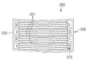
도 10은 본 발명의 다른 실시예에 따른 전극 조립체 제조방법에서 스택과정을 통해 적층된 전극 조립체를 나타낸 정면도이다.
도 11은 본 발명의 다른 실시예에 따른 전극 조립체 제조방법의 라미네이션 과정을 나타낸 측면도이다.
도 12는 본 발명의 다른 실시예에 따른 전극 조립체 제조방법으로 제조된 전극 조립체를 나타낸 사시도이다. 1 is a front view showing a stacking process in a method of manufacturing an electrode assembly according to an embodiment of the present invention.
2 is a front view showing an electrode assembly stacked through a stacking process in a method of manufacturing an electrode assembly according to an embodiment of the present invention.
3 is a side view showing a state before pressing the electrode assembly in the lamination process of the electrode assembly manufacturing method according to an embodiment of the present invention.
4 is a side view showing a state in which an electrode assembly is pressed during a lamination process in a method of manufacturing an electrode assembly according to an embodiment of the present invention.
5 is a perspective view showing an electrode assembly manufactured by a method of manufacturing an electrode assembly according to an embodiment of the present invention.
6 is a perspective view showing a state before the electrode assembly and the shape maintaining housing are coupled in the shape maintenance process of the electrode assembly manufacturing method according to an embodiment of the present invention.
7 is a perspective view showing a state in which an electrode assembly and a shape maintaining housing are coupled in a shape maintenance process in a method of manufacturing an electrode assembly according to an embodiment of the present invention.
8 is a side view showing a unit cell formation process in a method of manufacturing an electrode assembly according to another embodiment of the present invention.
9 is a front view showing a stacking process in a method of manufacturing an electrode assembly according to another embodiment of the present invention.
10 is a front view showing an electrode assembly stacked through a stacking process in a method of manufacturing an electrode assembly according to another embodiment of the present invention.
11 is a side view showing a lamination process of a method of manufacturing an electrode assembly according to another embodiment of the present invention.
12 is a perspective view showing an electrode assembly manufactured by a method of manufacturing an electrode assembly according to another embodiment of the present invention.
본 발명의 목적, 특정한 장점들 및 신규한 특징들은 첨부된 도면들과 연관되어지는 이하의 상세한 설명과 바람직한 실시예들로부터 더욱 명백해질 것이다. 본 명세서에서 각 도면의 구성요소들에 참조번호를 부가함에 있어서, 동일한 구성 요소들에 한해서는 비록 다른 도면상에 표시되더라도 가능한 한 동일한 번호를 가지도록 하고 있음에 유의하여야 한다. 또한, 본 발명은 여러 가지 상이한 형태로 구현될 수 있으며 여기에서 설명하는 실시예에 한정되지 않는다. 그리고, 본 발명을 설명함에 있어서, 본 발명의 요지를 불필요하게 흐릴 수 있는 관련된 공지 기술에 대한 상세한 설명은 생략하도록 한다. The objects, specific advantages and novel features of the present invention will become more apparent from the following detailed description and preferred embodiments that are associated with the accompanying drawings. In the present specification, in adding reference numerals to elements of each drawing, it should be noted that only the same elements have the same number as possible, even if they are indicated on different drawings. In addition, the present invention can be implemented in many different forms and is not limited to the embodiments described herein. In addition, in describing the present invention, detailed descriptions of related known technologies that may unnecessarily obscure the subject matter of the present invention will be omitted.
도 1은 본 발명의 일 실시예에 따른 전극 조립체 제조방법에서 스택과정을 나타낸 정면도이고, 도 2는 본 발명의 일 실시예에 따른 전극 조립체 제조방법의 스택과정을 통해 적층된 전극 조립체를 나타낸 정면도이다. 1 is a front view showing a stacking process in a method for manufacturing an electrode assembly according to an embodiment of the present invention, and FIG. 2 is a front view showing an electrode assembly stacked through a stacking process in a method for manufacturing an electrode assembly according to an embodiment of the present invention to be.
또한, 도 3은 본 발명의 일 실시예에 따른 전극 조립체 제조방법의 라미네이션 과정에서 전극 조립체를 가압하기 전 상태를 나타낸 측면도이며, 도 4는 본 발명의 일 실시예에 따른 전극 조립체 제조방법의 라미네이션 과정에서 전극 조립체를 가압한 상태를 나타낸 측면도이다. In addition, Figure 3 is a side view showing the state before pressing the electrode assembly in the lamination process of the electrode assembly manufacturing method according to an embodiment of the present invention, Figure 4 is a lamination of the electrode assembly manufacturing method according to an embodiment of the present invention It is a side view showing a state in which the electrode assembly is pressed in the process.
도 1 내지 도 4를 참고하면, 본 발명의 일 실시예에 따른 전극 조립체 제조방법은 분리막 시트(120)를 지그재그로 폴딩하며 분리막 시트(120) 사이사이에 유닛셀(110)을 위치시켜 전극 조립체(100)를 형성시키는 스택과정 및 전극 조립체(100)를 한 쌍의 히팅 프레스(heating press)(20)를 통해 열을 가하며 가압하여 유닛셀(110) 및 분리막 시트(120)를 상호 접합시켜 전극 조립체(100)를 라운드 형태로 형성시키는 라미네이션 과정을 포함한다. 1 to 4, the electrode assembly manufacturing method according to an embodiment of the present invention folds the
도 5는 본 발명의 일 실시예에 따른 전극 조립체 제조방법으로 제조된 전극 조립체를 나타낸 사시도이다. 5 is a perspective view showing an electrode assembly manufactured by a method of manufacturing an electrode assembly according to an embodiment of the present invention.
이하에서, 도 1 내지 도 5를 참조하여, 본 발명의 일 실시예인 전극 조립체(100) 제조방법에 대해 보다 상세히 설명하기로 한다. Hereinafter, a method of manufacturing the
도 1을 참고하면, 스택과정은 다수개의 유닛셀(Unit cell)(110) 및 분리막 시트(Sheet)(120)를 교대로 적층하되, 분리막 시트(120)를 지그재그(Zig Zag)로 폴딩(Folding)하며 분리막 시트(120) 사이사이에 유닛셀(110)을 위치시켜 지그재그 스택(Stack)된 전극 조립체(100)를 형성시킬 수 있다. Referring to FIG. 1, in the stacking process, a plurality of
또한, 스택과정은 분리막 시트(120)를 전극 조립체(100)의 4방향 중에서, 좌,우 방향(X)으로 번갈아 폴딩하고, 유닛셀(110)을 분리막 시트(120)의 폴딩 시 마다 좌,우 번갈아 적층할 수 있다. In addition, in the stacking process, the
아울러, 스택과정은 분리막 시트(120)와 유닛셀(110)을 서로 접착시키지 않으며 적층시킬 수 있다. In addition, in the stacking process, the
한편, 도 2를 참고하면, 스택과정은 분리막 시트(120)를 지그재그로 폴딩 시킨 후, 유닛셀(110)과 분리막 시트(120)의 지그재그 폴딩 부분을 전체적으로 더 둘러쌀 수 있다. 이때, 분리막 시트(120)는 지그 재그로 폴딩되는 폴딩 부위(121)와, 유닛셀(110)과 분리막 시트(120)의 폴딩부가 적층된 적층체를 전체적으로 감싸는 권취 부위(122)를 포함할 수 있다.On the other hand, referring to FIG. 2, the stacking process may further surround the zigzag folding portion of the
그리고, 도 1 및 도 3을 참고하면, 스택과정은 예를 들어 전극 조립체(100)의 길이(L)가 10 ~ 120 mm 가 형성되도록 전극 조립체(100)를 형성시킬 수 있다. 여기서, 스택과정은 구체적으로 예를 들어 전극 조립체(100)의 길이(L)가 30 ~ 78 mm 가 형성되도록 전극 조립체(100)를 형성시킬 수 있지만, 본 발명의 전극 조립체 제조방법을 통해 제조되는 전극 조립체(100)의 길이(L)가 상기의 범위들로 반드시 한정되는 것은 아니다. 이때, 전극 조립체(100)의 길이(L)는 예를 들어 전극 조립체(100)의 라운드(Round) 형태로 형성 전 상태에서 전,후 방향(Y)에 대한 전극 조립체(100)의 전체 길이일 수 있다.In addition, referring to FIGS. 1 and 3, the stack process may form the
도 1 및 도 5를 참고하면, 유닛셀(110)은 전극(113) 및 분리막(114)을 포함할 수 있다. 여기서, 전극(113)의 단부에는 전극 탭(118)이 형성될 수 있다.1 and 5, the
전극(113)은 양극(111) 및 음극(112)을 포함할 수 있다. 이때, 유닛셀(110)은 예를 들어 분리막(114)을 사이로 일측에 양극(111)이 위치되고, 타측에 음극(112)이 위치된 모노셀(Mono cell)로 이루어질 수 있다. The
양극(111)은 양극 집전체(미도시) 및 양극 집전체에 도포된 양극 활물질(미도시)을 포함하고, 음극(112)은 음극 집전체(미도시) 및 음극 집전체에 도포된 음극 활물질(미도시)을 포함할 수 있다. The
양극 집전체는 예를 들어 알루미늄(Al) 재질의 포일(foil)로 이루어질 수 있다. The positive electrode current collector may be made of, for example, aluminum (Al) foil.
양극 활물질은 일례로 리튬망간산화물, 리튬코발트산화물, 리튬니켈산화물, 리튬인산철, 또는 이들 중 1종 이상이 포함된 화합물 및 혼합물 등으로 이루어질 수 있다. The positive electrode active material may be made of, for example, lithium manganese oxide, lithium cobalt oxide, lithium nickel oxide, lithium iron phosphate, or a compound and a mixture containing at least one of them.
또한, 양극 활물질은 다른 예로 Hi Ni계 양극재로 이루어질 수 있다. 여기서, Hi Ni계 양극재는 LiNiMnCoO계, LiNiCoAl계 또는 LiMiMnCoAl계 중에서 어느 하나 이상을 포함하여 이루어질 수 있다. In addition, the positive electrode active material may be made of a Hi Ni-based positive electrode material as another example. Here, the Hi Ni-based positive electrode material may include any one or more of LiNiMnCoO-based, LiNiCoAl-based or LiMiMnCoAl-based.
음극 집전체는 예를 들어 구리(Cu) 또는 니켈(Ni) 재질로 이루어진 포일(foil)로 이루어질 수 있다. The negative electrode current collector may be made of, for example, a foil made of copper (Cu) or nickel (Ni).
음극 활물질은 일례로 인조흑연을 포함하는 재질로 이루어질 수 있다. The negative electrode active material may be made of, for example, a material containing artificial graphite.
또한, 음극 활물질은 다른 예로 리튬금속, 리튬합금, 카본, 석유코크, 활성화 카본, 그래파이트, 실리콘 화합물, 주석 화합물, 티타늄 화합물 또는 이들의 합금으로 이루어질 수 있다. In addition, the negative electrode active material may be made of lithium metal, lithium alloy, carbon, petroleum coke, activated carbon, graphite, silicon compounds, tin compounds, titanium compounds or alloys thereof.
분리막(114)은 절연 재질로 이루어져 양극(111)과 음극(112) 사이를 전기적으로 절연할 수 있다. The
여기서, 분리막(114)은 일례로 미다공성을 가지는 폴리에칠렌, 폴리프로필렌 또는 이들의 조합에 의해 제조되는 다층 필름이나, 폴리비닐리덴 플루오라이드, 폴리에틸렌 옥사이드, 폴리아크릴로니트릴 또는 폴리비닐리덴 플루오라이드 헥사플루오로프로필렌 공중합체와 같은 고체 고분자 전해질용 또는 겔형 고분자 전해질용 고분자 필름일 수 있다. Here, the
한편, 분리막 시트(120)는 예를 들어 분리막(114)과 동일 재질로 이루어질 수 있다.Meanwhile, the
한편, 양극(111)의 단부에 양극 탭(116)이 더 형성되고, 음극(112)의 단부에 음극 탭(117)이 더 형성될 수 있다.Meanwhile, an
도 3 내지 도 5를 참고하면, 라미네이션 과정은 전극 조립체(100)의 양면을 한 쌍의 히팅 프레스(heating press)(20)를 통해 열을 가하며 가압하여 다수개의 유닛셀(110) 및 분리막 시트(120)를 상호 접합시킬 수 있다.3 to 5, the lamination process is performed by applying heat to both sides of the
또한, 라미네이션 과정은 한 쌍의 히팅 프레스(20)가 라운드(Round) 형태로 형성되어 전극 조립체(100)를 가압 시, 전극 조립체(100)를 라운드 형태로 형성시킬 수 있다.In addition, in the lamination process, a pair of heating presses 20 are formed in a round shape, and when the
아울러, 라미네이션 과정은 전극 조립체(100)의 4방향 중에서, 전,후 방향(Y)에 대하여 곡률이 형성되도록 전극 조립체(100)를 가압할 수 있다.In addition, the lamination process may press the
여기서, 라미네이션 과정은 전극 조립체(100)의 곡률 반경(R1)이 예를 들어 60 ~ 450 mm 되도록 전극 조립체(100)를 한 쌍의 히팅 프레스(20)로 가압할 수 있다. 이때, 라미네이션 과정은 전극 조립체(100)의 곡률 반경(R1)이 구체적으로 예를 들어 90 ~ 200 mm 되도록 전극 조립체(100)를 한 쌍의 히팅 프레스(20)로 가압할 수 있다. 이에 따라, 전극 조립체(100)의 곡률 반경(R1)이 90 mm 이상으로 형성되어 라운드(Round) 형태의 디바이스(Device)에 적용하기 용이할 수 있고, 전극 조립체(100)의 곡률 반경(R1)이 200 mm 이하로 형성되어 전극 조립체(100)가 꺾여 손상되거나 외력에 의해 크랙(Crack)이 발생되는 것을 방지 또는 현저히 저감시킬 수 있다.Here, the lamination process may press the
한편, 한 쌍의 상기 히팅 프레스(20)는 전극 조립체(100)의 상부를 가압하는 상부 프레스(21) 및 전극 조립체(100)의 하부를 가압하는 하부 프레스(22)를 포함할 수 있다.Meanwhile, the pair of heating presses 20 may include an
여기서, 예를 들어 상부 프레스(21)는 가압면(21a)은 볼록한 형태로 형성되고, 하부 프레스(22)의 가압면(22a)은 오목한 형태로 형성될 수 있다. 즉, 상부 프레스(21)의 볼록하게 라운드 형성된 가압면(21a)과, 하부 프레스(22)의 오목하게 라운드 형성된 가압면(22a) 사이에 유닛셀(110)과 분리막 시트(120)의 적층체를 위치시킨 후 가열 및 가압하면 유닛셀(110)과 분리막 시트(120)가 벤딩되며 접합되어, 라운드 형태의 전극 조립체(100)를 형성시킬 수 있다.Here, for example, the
여기서, 상부 프레스(21) 및 하부 프레스(22)에서 상호 마주보는 가압면(21a,22a)의 곡률 반경(R1)은 예를 들어 각각 60 ~ 450 mm 로 형성될 수 있다Here, the radius of curvature R1 of the
이때, 상부 프레스(21) 및 하부 프레스(22)에서 상호 마주보는 가압면(21a,22a)의 곡률 반경(R1)은 구체적으로 예를 들어 각각 90 ~ 200 mm 로 형성될 수 있다. 여기서, 곡률 반경(R1)은 가압면(21a,22a)의 곡선을 따라 연장하여 형성되는 가상의 원에서 반지름일 수 있다.At this time, the radius of curvature R1 of the
도 1, 도 4 및 도 5를 참고하면, 상기와 같이 구성된 본 발명의 일 실시예에 따른 전극 조립체 제조방법은, 스택 과정에서 분리막 시트(120)와 유닛셀(110)을 서로 접착시키지 않고 지그재그로 적층시킨다. 이에 따라, 이후 라미네이션 과정에서 분리막 시트(120)와 유닛셀(110)을 가압 및 가열하며 접합시킬 때, 라운드 형태로 접합시키기 용이할 수 있다. 즉, 분리막 시트(120)와 유닛셀(110) 사이를 접합시킨 후 라미네이션 과정을 통해 벤딩(Bending)시켜 라운드 형태의 전극 조립체(100)를 형성시키면, 분리막 시트(120)와 유닛셀(110) 사이의 접착력이 전극 조립체(100)가 다시 평면 형태로 회귀할려는 복원력으로 작용할 수 있다. 하지만, 스택과정에서 분리막 시트(120)와 유닛셀(110)을 접합시키지 않고 라미네이션 과정에서 벤딩하여 접합시켜 라운드 형태의 전극 조립체(100)를 형성시키면, 벤딩된 상태에서 분리막 시트(120)와 유닛셀(110)이 접합되므로 분리막 시트(120)와 유닛셀(110) 사이의 접착력은 벤딩된 상태를 유지하는 벤딩 유지력을 발생시킬 수 있다. 즉, 분리막 시트(120)와 유닛셀(110)이 라미네이션 과정에서 라운드 형태인 상태로 서로 접합되면, 분리막 시트(120)와 유닛셀(110)의 접합력에 의해 전극 조립체(100)가 벤딩된 라운드 형태의 전극 조립체(100)를 유지시키기 용이할 수 있다(라미네이션 과정이 완료된 전극 조립체(100)가 도로 평평하게 펴지지 않고 라운드 형태를 유지하기가 용이하다는 의미임).1, 4, and 5, the electrode assembly manufacturing method according to an embodiment of the present invention configured as described above is zigzag without bonding the
도 6은 본 발명의 일 실시예에 따른 전극 조립체 제조방법의 형태 유지 과정에서 전극 조립체와 형태 유지 하우징이 결합하기 전 상태를 나타낸 사시도이고, 도 7은 본 발명의 일 실시예에 따른 전극 조립체 제조방법의 형태 유지 과정에서 전극 조립체와 형태 유지 하우징이 결합된 상태를 나타낸 사시도이다.6 is a perspective view showing a state before the electrode assembly and the shape maintaining housing are coupled in the shape maintaining process of the electrode assembly manufacturing method according to an embodiment of the present invention, and FIG. 7 is a manufacturing method of the electrode assembly according to an embodiment of the present invention. It is a perspective view showing a state in which the electrode assembly and the shape-retaining housing are coupled in the process of maintaining the shape of the method.
본 발명의 일 실시예에 따른 전극 조립체 제조방법은 전극 조립체(100)의 라운드 형태가 유지되도록 형태 유지 하우징(130)으로 전극 조립체(100)를 감싸는 형태 유지과정을 더 포함할 수 있다.The electrode assembly manufacturing method according to an embodiment of the present invention may further include a shape preservation process of wrapping the
형태 유지과정은 라미네이션 과정을 통해 형성된 전극 조립체(100)의 라운드 형태가 유지되도록 형태 유지 하우징(130)으로 전극 조립체(100)를 감쌀 수 있다. The shape maintaining process may wrap the
이때, 형태 유지 하우징(130)의 내측은 전극 조립체(100)의 라운드 형태에 대응되는 형태로 형성될 수 있다.At this time, the inside of the shape-retaining
이에 따라, 전극 조립체(100)가 라운드 형태에서 평면 형태로 되돌아 가는 것을 억제하여 지속적으로 라운드 형태를 유지하기 용이할 수 있다.Accordingly, it is possible to easily maintain the round shape by suppressing the
여기서, 본 발명의 일 실시예에 따른 전극 조립체 제조방법으로 전극 조립체를 제조 시, 일례로 도 5를 참고하면, 유닛셀(110) 및 분리막 시트(120)를 포함하는 전극 조립체(100)를 형성시킬 수 있고, 다른 예로, 도 7을 참고하면, 유닛셀(110)과, 분리막 시트(120) 및 형태 유지 하우징(130)을 포함하는 전극 조립체(100')를 형성시킬 수 있다.Here, when manufacturing the electrode assembly by the electrode assembly manufacturing method according to an embodiment of the present invention, referring to FIG. 5 as an example, forming the
이하에서는 본 발명의 다른 실시예에 따른 전극 조립체 제조방법을 설명하기로 한다. Hereinafter, a method of manufacturing an electrode assembly according to another embodiment of the present invention will be described.
도 8은 본 발명의 다른 실시예에 따른 전극 조립체 제조방법에서 유닛셀 형성과정을 나타낸 측면도이고, 도 9는 본 발명의 다른 실시예에 따른 전극 조립체 제조방법에서 스택과정을 나타낸 정면도이며, 도 10은 본 발명의 다른 실시예에 따른 전극 조립체 제조방법에서 스택과정을 통해 적층된 전극 조립체를 나타낸 정면도이다. 8 is a side view showing a unit cell formation process in an electrode assembly manufacturing method according to another embodiment of the present invention, and FIG. 9 is a front view showing a stacking process in an electrode assembly manufacturing method according to another embodiment of the present invention, and FIG. Is a front view showing an electrode assembly stacked through a stacking process in a method of manufacturing an electrode assembly according to another embodiment of the present invention.
또한, 도 11은 본 발명의 다른 실시예에 따른 전극 조립체 제조방법의 라미네이션 과정을 나타낸 측면도이며, 도 12는 본 발명의 다른 실시예에 따른 전극 조립체 제조방법으로 제조된 전극 조립체를 나타낸 사시도이다. In addition, FIG. 11 is a side view showing a lamination process of an electrode assembly manufacturing method according to another embodiment of the present invention, and FIG. 12 is a perspective view showing an electrode assembly manufactured by the electrode assembly manufacturing method according to another embodiment of the present invention.
도 8 내지 도 11을 참고하면, 본 발명의 다른 실시예에 따른 전극 조립체 제조방법은 유닛셀(210)을 라운드 형태로 형성시키는 유닛셀 형성과정과, 분리막 시트(220)를 지그재그로 폴딩하며 분리막 시트(220) 사이사이에 유닛셀(210)을 위치시켜 전극 조립체(200)를 형성시키는 스택과정 및 전극 조립체(200)를 한 쌍의 히팅 프레스(heating press)(20)를 통해 열을 가하며 가압하여 유닛셀(210) 및 분리막 시트(220)를 상호 접합시켜 전극 조립체(200)를 라운드 형태로 형성시키는 라미네이션 과정을 포함한다. 8 to 11, a method of manufacturing an electrode assembly according to another embodiment of the present invention includes a unit cell forming process of forming the
본 발명의 다른 실시예에 따른 전극 조립체 제조방법은 전술한 일 실시예에 따른 전극 조립체 제조방법과 비교할 때, 유닛셀(210)을 라운드 형태로 형성시키는 유닛셀 형성과정을 더 포함하는 차이가 있을 수 있다. The electrode assembly manufacturing method according to another embodiment of the present invention may have a difference further comprising a unit cell forming process of forming the
따라서, 본 실시예는 일 실시예와 중복되는 내용은 간략히 기술하고, 차이점을 중심으로 기술하도록 한다. Therefore, in this embodiment, contents overlapping with one embodiment are briefly described, and the differences are described.
도 8을 참고하면, 본 발명의 다른 실시예에 따른 전극 조립체 제조방법에서 유닛셀 형성과정은 유닛셀(210)이 라운드 형태로 형성되도록 전극(213) 및 분리막(214)을 적층하여 히트 프레스(Heat press)할 수 있다. Referring to FIG. 8, in the method of manufacturing an electrode assembly according to another embodiment of the present invention, in the process of forming a unit cell, an
보다 상세히, 유닛셀 형성과정은 전극(213) 및 분리막(214)의 양면을 한 쌍의 히팅(Heating) 가압부(10)를 통해 가열 및 가압하여 상호 접합시킬 수 있다. 이때, 상부 가압부(11) 및 하부 가압부(12)로 구성된 한 쌍의 히팅 가압부(10)의 가압면은 라운드 형태로 형성되어 전극(213) 및 분리막(214)의 가열 및 가압하여 라운드 형태의 유닛셀(210)을 형성시킬 수 있다. 이에 따라, 라운드 형태의 전극 조립체(200)를 형성시키기가 보다 용이할 수 있다.In more detail, in the unit cell formation process, both surfaces of the
도 9를 참고하면, 스택과정은 다수개의 유닛셀(210) 및 분리막 시트(220)를 교대로 적층하되, 분리막 시트(220)를 지그재그로 폴딩하며 분리막 시트(220) 사이사이에 유닛셀(210)을 위치시켜 지그재그 스택(Stack)된 전극 조립체(200)를 형성시킬 수 있다.Referring to FIG. 9, in the stacking process, a plurality of
이때, 스택과정은 분리막 시트(220)를 유닛셀(210)의 라운드 형태에 대응되도록 유닛셀(210)에 밀착시키며 지그재그 폴딩할 수 있다. In this case, the stacking process may zigzag folding the
또한, 스택과정은 분리막 시트(220)를 전극 조립체(200)의 4방향에서, 좌,우 방향(X)으로 번갈아 폴딩하고, 유닛셀(210)을 분리막 시트(220)의 폴딩 시 마다 좌,우 번갈아 적층할 수 있다. Further, in the stacking process, the
아울러, 스택 과정은 분리막 시트(220)와 유닛셀(210)을 서로 접착시키지 않으며 적층시킨다. In addition, in the stacking process, the
한편, 도 10을 참고하면, 스택과정은 분리막 시트(220)를 지그재그로 폴딩 시킨 후, 유닛셀(210)과 분리막 시트(220)의 지그재그 폴딩 부분을 전체적으로 더 둘러쌀 수 있다. 이때, 분리막 시트(220)는 지그 재그로 폴딩되는 폴딩 부위(221)와, 유닛셀(210)과 분리막 시트(220)의 폴딩부가 적층된 적층체를 전체적으로 감싸는 권취 부위를(222) 포함할 수 있다.On the other hand, referring to FIG. 10, the stacking process may further surround the zigzag folding portion of the
도 9 및 도 12를 참고하면, 유닛셀(210)은 전극(213) 및 분리막(214)을 포함할 수 있다. 여기서, 전극(213)의 단부에는 전극 탭(218)이 형성될 수 있다.9 and 12, the
여기서, 전극(213)은 양극(211) 및 음극(212)을 포함할 수 있다. 이때, 양극(211)의 단부에 양극 탭(216)이 더 형성되고, 음극(212)의 단부에 음극 탭(217)이 더 형성될 수 있다.Here, the
한편, 유닛셀(210)은 분리막(214)을 사이로 일측에 양극(211)이 위치되고, 타측에 음극(212)이 위치된 모노셀(Mono cell)로 이루어질 수 있다. On the other hand, the
도 11 및 도 12를 참고하면, 라미네이션 과정은 전극 조립체(200)의 양면을 한 쌍의 히팅 프레스(heating press)(20)를 통해 열을 가하며 가압하여 다수개의 유닛셀(210) 및 분리막 시트(220)를 상호 접합시킬 수 있다.Referring to FIGS. 11 and 12, the lamination process is performed by applying pressure to both sides of the
또한, 라미네이션 과정은 한 쌍의 히팅 프레스(20)가 라운드(Round) 형태로 형성되어 전극 조립체(200)를 가압 시 전극 조립체(200)를 라운드 형태로 형성시킬 수 있다.In addition, in the lamination process, a pair of heating presses 20 may be formed in a round shape to form the
아울러, 라미네이션 과정은 전극 조립체(200)의 4방향 중에서, 전,후 방향(Y)에 대하여 곡률이 형성되도록 전극 조립체(200)를 가압할 수 있다.In addition, in the lamination process, among the four directions of the
한편, 라미네이션 과정은 전극 조립체(200)의 곡률 반경이 예를 들어 60 ~ 450 mm 되도록 전극 조립체(200)를 한 쌍의 히팅 프레스(20)로 가압할 수 있다. Meanwhile, the lamination process may press the
여기서, 라미네이션 과정은 전극 조립체(200)의 곡률 반경이 구체적으로 예를 들어 90 ~ 200 mm 되도록 전극 조립체(200)를 한 쌍의 히팅 프레스(20)로 가압할 수 있다. Here, the lamination process may press the
도 8 내지 도 12를 참고하면, 상기와 같이 구성된 본 발명의 다른 실시예에 따른 전극 조립체 제조방법은, 유닛셀(210) 및 분리막 시트(220)를 적층시키는 스택과정 수행 이전에 유닛셀(210)이 라운드 형태로 형성되도록 전극(213) 및 분리막(214)을 적층하여 히트 프레스(Heat press)하는 유닛셀 형성과정을 먼저 수행할 수 있다. 이후, 스택과정에서 유닛셀(210) 및 분리막 시트(220)를 적층 후, 라미네이션 과정에서 유닛셀(210) 및 분리막 시트(220)를 라운드 형태로 형성시켜 전극 조립체(200)를 제조할 수 있다.8 to 12, the electrode assembly manufacturing method according to another embodiment of the present invention configured as described above, prior to performing the stacking process of stacking the
따라서, 유닛셀 형성과정을 통해 유닛셀(210) 내부의 전극(213), 분리막(214) 간 접착층이 이후 라미네이션 과정에서 다시 한번 라운드 형태의 접착층을 형성하므로 라운드 유지력이 더욱 좋아질 수 있다.Accordingly, the adhesive layer between the
즉, 유닛셀(210) 및 분리막 시트(220)를 라운드 형태로 접합시켜 유닛셀(210)과 분리막 시트(220) 사이에 라운드 접착층을 형성시킬 때 보다, 유닛셀(210) 내부의 전극(213) 및 분리막(214) 사이를 라운드 형태로 접합시켜 라운드 접착층을 형성시킨 후, 유닛셀(210) 및 분리막 시트(220)를 라운드 형태로 접합시켜 라운드 접착층을 형성시킴에 따라 2중의 라운드 접착층이 형성되어 전극 조립체(200)의 라운드 유지력이 보다 증가될 수 있다.That is, rather than forming a round adhesive layer between the
한편, 도 5, 도 7 및 도 12를 참고하면, 본 발명의 실시예에 따른 전극 조립체(100,100',200)는, 전술한 일 실시예에 따른 전극 조립체 제조방법 또는 본 발명의 다른 실시예에 따른 전극 조립체 제조방법에 따른 전극 조립체 제조방법으로 제조될 수 있다.Meanwhile, referring to FIGS. 5, 7 and 12, the
한편, 도 5, 도 7 및 도 12를 참고하면, 본 발명의 실시예에 따른 이차전지는, 전술한 일 실시예에 따른 전극 조립체 제조방법 또는 본 발명의 다른 실시예에 따른 전극 조립체 제조방법에 따른 전극 조립체 제조방법으로 제조된 전극 조립체(100,100',200)를 포함할 수 있다. 여기서, 이차전지(미도시)는 전극 조립체(100,100',200) 및 전극 조립체(100,100',200)를 수용하는 전지 케이스(미도시)를 포함할 수 있다. 여기서, 이차전지에 대한 구체적인 구조는 당업계에 공지된 사항으로 상세한 설명은 생략하기로 한다.Meanwhile, referring to FIGS. 5, 7, and 12, a secondary battery according to an embodiment of the present invention includes an electrode assembly manufacturing method according to one embodiment described above or an electrode assembly manufacturing method according to another embodiment of the present invention. It may include the electrode assembly (100,100', 200) manufactured by the electrode assembly manufacturing method according to. Here, the secondary battery (not shown) may include
이상 본 발명을 구체적인 실시예를 통하여 상세히 설명하였으나, 이는 본 발명을 구체적으로 설명하기 위한 것으로, 본 발명에 따른 전극 조립체 제조방법과, 이를 통해 제조된 전극 및 이차전지는 이에 한정되지 않는다. 본 발명의 기술적 사상 내에서 당해 분야의 통상의 지식을 가진 자에 의해 다양한 실시가 가능하다고 할 것이다. The present invention has been described in detail through specific examples, but this is for specifically describing the present invention, and the method of manufacturing the electrode assembly according to the present invention and the electrodes and secondary batteries manufactured therefrom are not limited thereto. It will be said that various implementations are possible by a person skilled in the art within the technical spirit of the present invention.
또한, 발명의 구체적인 보호 범위는 첨부된 특허청구범위에 의하여 명확해질 것이다. In addition, the specific protection scope of the invention will be clarified by the appended claims.
10: 히팅 가압부
21: 상부 가압부
12: 하부 가압부
20: 히팅 프레스
21: 상부 프레스
21a: 가압면
22: 하부 프레스
22a: 가압면
100,100',200: 전극 조립체
110,210: 유닛셀
111,211: 양극
112,222: 음극
113,223: 전극
114,214 분리막
116,216: 양극 탭
117,217: 음극 탭
118,218: 전극 탭
120,220: 분리막 시트
121,221: 폴딩 부위
122,222: 권취 부위
130: 형태 유지 하우징
X: 좌,우 방향
Y: 전,후 방향
R1,R2: 곡률 반경10: heating pressurization part
21: upper pressing part
12: lower pressing part
20: heating press
21: upper press
21a: pressing surface
22: lower press
22a: pressing surface
100,100',200: electrode assembly
110,210: unit cell
111,211: anode
112,222: cathode
113,223: electrode
114,214 separator
116,216: positive tap
117,217: negative tab
118,218: electrode tab
120,220: separator sheet
121,221: folding portion
122,222: winding site
130: shape retention housing
X: Left, right direction
Y: front and rear direction
R1,R2: radius of curvature
Claims (14)
상기 전극 조립체의 양면을 한 쌍의 히팅 프레스(heating press)를 통해 열을 가하며 가압하여 다수개의 상기 유닛셀 및 상기 분리막 시트를 상호 접합시키는 라미네이션 과정;을 포함하고,
상기 라미네이션 과정은 상기 한 쌍의 히팅 프레스가 라운드(Round) 형태로 형성되어 상기 전극 조립체를 가압 시 상기 전극 조립체를 라운드 형태로 형성시키는 전극 조립체 제조방법.A stacking process of alternately stacking a plurality of unit cells and separator sheets including electrodes and separators, folding the separator sheets in a zigzag manner, and positioning the unit cells between the separator sheets to form a zigzag stacked electrode assembly; And
Including; a lamination process of bonding the plurality of unit cells and the separator sheet to each other by applying heat and pressing both sides of the electrode assembly through a pair of heating presses,
In the lamination process, the pair of heating presses are formed in a round shape to form the electrode assembly in a round shape when pressing the electrode assembly.
상기 스택과정은
상기 분리막 시트를 상기 전극 조립체의 4방향 중에서, 좌,우 방향으로 번갈아 폴딩하고,
상기 유닛셀을 상기 분리막 시트의 폴딩 시 마다 좌,우 번갈아 적층하는 전극 조립체 제조방법.The method according to claim 1,
The stacking process is
The separator sheet is alternately folded in left and right directions among the four directions of the electrode assembly,
An electrode assembly manufacturing method in which the unit cells are alternately stacked left and right each time the separator sheet is folded.
상기 라미네이션 과정은
상기 전극 조립체의 4방향 중에서, 전,후 방향에 대하여 곡률이 형성되도록 상기 전극 조립체를 가압하는 전극 조립체 제조방법.The method according to claim 2,
The lamination process is
An electrode assembly manufacturing method for pressing the electrode assembly so that a curvature is formed in front and rear directions among the four directions of the electrode assembly.
상기 스택과정은 상기 전극 조립체의 길이가 30 ~ 78 mm 가 형성되도록 상기 전극 조립체를 형성시키고,
상기 라미네이션 과정은 상기 전극 조립체의 곡률 반경이 90 ~ 200 mm 되도록 상기 전극 조립체를 상기 한 쌍의 히팅 프레스로 가압하는 전극 조립체 제조방법.The method of claim 3,
In the stacking process, the electrode assembly is formed so that the length of the electrode assembly is 30 to 78 mm,
The lamination process is a method of manufacturing an electrode assembly in which the electrode assembly is pressed with the pair of heating presses so that the curvature radius of the electrode assembly is 90 to 200 mm.
한 쌍의 상기 히팅 프레스는 상기 전극 조립체의 상부를 가압하는 상부 프레스 및 상기 전극 조립체의 하부를 가압하는 하부 프레스를 포함하고,
상기 상부 프레스 및 상기 하부 프레스에서 상호 마주보는 가압면의 곡률 반경은 각각 90 ~ 200 mm 로 형성되는 전극 조립체 제조방법.The method of claim 3,
The pair of heating presses include an upper press that presses an upper portion of the electrode assembly and a lower press that presses a lower portion of the electrode assembly,
The electrode assembly manufacturing method in which the curvature radius of the pressing surfaces facing each other in the upper press and the lower press are respectively 90 to 200 mm.
상기 라미네이션 과정을 통해 형성된 상기 전극 조립체의 라운드 형태가 유지되도록 형태 유지 하우징으로 상기 전극 조립체를 감싸는 형태 유지과정을 더 포함하는 전극 조립체 제조방법.The method according to claim 1,
The electrode assembly manufacturing method further comprising a shape maintaining process of surrounding the electrode assembly with a shape maintaining housing so that the round shape of the electrode assembly formed through the lamination process is maintained.
상기 형태 유지 하우징의 내측은 상기 전극 조립체의 라운드 형태에 대응되는 형태로 형성되는 전극 조립체 제조방법.The method according to claim 6,
An electrode assembly manufacturing method in which the inner side of the shape maintaining housing is formed in a shape corresponding to the round shape of the electrode assembly.
상기 스택과정 이전에,
상기 유닛셀이 라운드 형태로 형성되도록 상기 전극 및 상기 분리막을 적층하여 히트 프레스(Heat press)하는 유닛셀 형성과정을 더 포함하는 전극 조립체 제조방법.The method according to claim 1,
Before the stacking process,
The electrode assembly manufacturing method further comprising a process of forming a unit cell by heat pressing by stacking the electrode and the separator so that the unit cell is formed in a round shape.
상기 유닛셀 형성과정은
상기 라미네이션 과정을 통해 형성될 상기 전극 조립체의 곡률에 대응되는 곡률이 형성되도록 상기 유닛셀을 형성시키는 전극 조립체 제조방법.The method according to claim 8,
The unit cell formation process
An electrode assembly manufacturing method of forming the unit cell such that a curvature corresponding to a curvature of the electrode assembly to be formed through the lamination process is formed.
상기 스택과정은
상기 분리막 시트를 상기 유닛셀의 라운드 형태에 대응되도록 상기 유닛셀에 밀착시키며 지그재그 폴딩하는 전극 조립체 제조방법.The method of claim 9,
The stacking process is
An electrode assembly manufacturing method in which the separator sheet is in close contact with the unit cell so as to correspond to the round shape of the unit cell and zigzag folded.
상기 유닛셀은
상기 분리막을 사이로 일측에 양극이 위치되고, 타측에 음극이 위치된 모노셀로 이루어지는 전극 조립체 제조방법.The method according to any one of claims 1 to 10,
The unit cell is
An electrode assembly manufacturing method comprising a monocell in which an anode is positioned on one side and a cathode is positioned on the other side through the separator.
상기 스택 과정은
상기 분리막 시트와 상기 유닛셀을 서로 접착시키지 않으며 적층시키는 전극 조립체 제조방법.The method according to any one of claims 1 to 10,
The stacking process is
An electrode assembly manufacturing method in which the separator sheet and the unit cell are not adhered to each other and are laminated.
Priority Applications (5)
| Application Number | Priority Date | Filing Date | Title |
|---|---|---|---|
| KR1020190013849A KR20200095896A (en) | 2019-02-01 | 2019-02-01 | Electrode assembly manufacturing method, and electrode assembly and rechargeable battery manufactured from thereof |
| PCT/KR2020/001520 WO2020159306A1 (en) | 2019-02-01 | 2020-01-31 | Method for manufacturing electrode assembly, and electrode and secondary battery manufactured thereby |
| US17/427,133 US20220246974A1 (en) | 2019-02-01 | 2020-01-31 | Method for manufacturing electrode assembly, electrode assembly manufactured therethrough, and secondary battery |
| CN202080009754.7A CN113692670A (en) | 2019-02-01 | 2020-01-31 | Method of manufacturing electrode assembly, electrode manufactured by the method, and secondary battery |
| EP20749322.2A EP3905417A4 (en) | 2019-02-01 | 2020-01-31 | Method for manufacturing electrode assembly, and electrode and secondary battery manufactured thereby |
Applications Claiming Priority (1)
| Application Number | Priority Date | Filing Date | Title |
|---|---|---|---|
| KR1020190013849A KR20200095896A (en) | 2019-02-01 | 2019-02-01 | Electrode assembly manufacturing method, and electrode assembly and rechargeable battery manufactured from thereof |
Publications (1)
| Publication Number | Publication Date |
|---|---|
| KR20200095896A true KR20200095896A (en) | 2020-08-11 |
Family
ID=71841204
Family Applications (1)
| Application Number | Title | Priority Date | Filing Date |
|---|---|---|---|
| KR1020190013849A KR20200095896A (en) | 2019-02-01 | 2019-02-01 | Electrode assembly manufacturing method, and electrode assembly and rechargeable battery manufactured from thereof |
Country Status (5)
| Country | Link |
|---|---|
| US (1) | US20220246974A1 (en) |
| EP (1) | EP3905417A4 (en) |
| KR (1) | KR20200095896A (en) |
| CN (1) | CN113692670A (en) |
| WO (1) | WO2020159306A1 (en) |
Cited By (5)
| Publication number | Priority date | Publication date | Assignee | Title |
|---|---|---|---|---|
| CN112563581A (en) * | 2020-12-08 | 2021-03-26 | 合肥国轩高科动力能源有限公司 | Integrative device of dry film-making |
| CN112909351A (en) * | 2021-03-31 | 2021-06-04 | 蜂巢能源科技有限公司 | Lamination process |
| WO2023018310A1 (en) * | 2021-08-13 | 2023-02-16 | 주식회사 엘지에너지솔루션 | Electrode assemblly for secondary battery, and manufacturing method therefor |
| WO2023043196A1 (en) * | 2021-09-14 | 2023-03-23 | 주식회사 엘지에너지솔루션 | Electrode assembly, secondary battery comprising same, secondary battery manufacturing method for manufacturing same, and secondary battery manufacturing device used therein |
| EP4207411A3 (en) * | 2021-12-31 | 2023-10-04 | SK On Co., Ltd. | Electrode assembly for secondary battery and method of manufacturing same |
Families Citing this family (3)
| Publication number | Priority date | Publication date | Assignee | Title |
|---|---|---|---|---|
| CN112864450A (en) * | 2021-01-14 | 2021-05-28 | 天能帅福得能源股份有限公司 | Lithium ion battery and preparation method thereof |
| CN113555595B (en) * | 2021-07-23 | 2023-01-10 | 蜂巢能源科技有限公司 | Thermal lamination equipment and thermal lamination method |
| WO2023081524A2 (en) * | 2021-11-08 | 2023-05-11 | Advanced Cell Engineering, Inc. | Lithium ion cathodes and cells suitable for large-format batteries and large-format batteries containing lithium ion cathodes |
Citations (1)
| Publication number | Priority date | Publication date | Assignee | Title |
|---|---|---|---|---|
| KR20140015647A (en) | 2012-06-22 | 2014-02-07 | 주식회사 엘지화학 | Electrode assembly, manufacture thereof, and secondary batteries including same |
Family Cites Families (9)
| Publication number | Priority date | Publication date | Assignee | Title |
|---|---|---|---|---|
| US8426069B2 (en) * | 2005-05-10 | 2013-04-23 | Panasonic Corporation | Battery having a belt-like separator |
| KR101049841B1 (en) * | 2008-03-12 | 2011-07-15 | 주식회사 엘지화학 | Curved battery cell and battery pack comprising the same |
| KR101349205B1 (en) * | 2011-04-15 | 2014-01-08 | 에스케이이노베이션 주식회사 | Multi-Input Stacking Apparatus for Secondary Battery and Method of the same |
| KR101567674B1 (en) * | 2013-02-15 | 2015-11-10 | 주식회사 엘지화학 | Manufacturing method for electrode assembly |
| CN103401024A (en) * | 2013-08-21 | 2013-11-20 | 广州丰江电池新技术股份有限公司 | Arc battery cell, arc single cell, arc cell combination structure and manufacturing method |
| KR101784033B1 (en) * | 2013-10-30 | 2017-10-10 | 주식회사 엘지화학 | Method for electrode assembly |
| KR101663351B1 (en) * | 2013-10-31 | 2016-10-06 | 주식회사 엘지화학 | Cell for electrochemical device and preparation method thereof |
| KR101811475B1 (en) * | 2013-12-19 | 2017-12-21 | 주식회사 엘지화학 | A Manufacturing Method for Curved Radical Cell or Battery and a Radical Cell thereby |
| KR101879911B1 (en) * | 2015-03-27 | 2018-07-18 | 주식회사 엘지화학 | Method for Production of Curved-Shaped Battery Cell |
-
2019
- 2019-02-01 KR KR1020190013849A patent/KR20200095896A/en not_active Application Discontinuation
-
2020
- 2020-01-31 US US17/427,133 patent/US20220246974A1/en active Pending
- 2020-01-31 WO PCT/KR2020/001520 patent/WO2020159306A1/en unknown
- 2020-01-31 CN CN202080009754.7A patent/CN113692670A/en active Pending
- 2020-01-31 EP EP20749322.2A patent/EP3905417A4/en active Pending
Patent Citations (1)
| Publication number | Priority date | Publication date | Assignee | Title |
|---|---|---|---|---|
| KR20140015647A (en) | 2012-06-22 | 2014-02-07 | 주식회사 엘지화학 | Electrode assembly, manufacture thereof, and secondary batteries including same |
Cited By (5)
| Publication number | Priority date | Publication date | Assignee | Title |
|---|---|---|---|---|
| CN112563581A (en) * | 2020-12-08 | 2021-03-26 | 合肥国轩高科动力能源有限公司 | Integrative device of dry film-making |
| CN112909351A (en) * | 2021-03-31 | 2021-06-04 | 蜂巢能源科技有限公司 | Lamination process |
| WO2023018310A1 (en) * | 2021-08-13 | 2023-02-16 | 주식회사 엘지에너지솔루션 | Electrode assemblly for secondary battery, and manufacturing method therefor |
| WO2023043196A1 (en) * | 2021-09-14 | 2023-03-23 | 주식회사 엘지에너지솔루션 | Electrode assembly, secondary battery comprising same, secondary battery manufacturing method for manufacturing same, and secondary battery manufacturing device used therein |
| EP4207411A3 (en) * | 2021-12-31 | 2023-10-04 | SK On Co., Ltd. | Electrode assembly for secondary battery and method of manufacturing same |
Also Published As
| Publication number | Publication date |
|---|---|
| EP3905417A4 (en) | 2022-02-23 |
| CN113692670A (en) | 2021-11-23 |
| EP3905417A1 (en) | 2021-11-03 |
| WO2020159306A1 (en) | 2020-08-06 |
| US20220246974A1 (en) | 2022-08-04 |
Similar Documents
| Publication | Publication Date | Title |
|---|---|---|
| KR20200095896A (en) | Electrode assembly manufacturing method, and electrode assembly and rechargeable battery manufactured from thereof | |
| KR101395016B1 (en) | A Stepwise Electrode Assembly, and Battery Cell, Battery Pack and Device Comprising the Same | |
| KR102217451B1 (en) | Rechargeable battery and the manufacturing method, and press block for rechargeable battery | |
| KR101414092B1 (en) | Stepwise Electrode Assembly, Secondary Battery, Battery Pack and Devide comprising the Stepwise Electrode Assembly, and Method for preparing the Stepwise Electrode Assembly | |
| US20230246222A1 (en) | Secondary Battery And Method For Manufacturing The Same | |
| KR101395017B1 (en) | A Stepwise Electrode Assembly, and Battery Cell, Battery Pack and Device Comprising the Same | |
| KR101379957B1 (en) | A Stepwise Electrode Assembly, and a Battery Cell, Battery Pack and Device Comprising the Same | |
| KR101575984B1 (en) | Electrode assembly having a good bondability of tab, battery cell and device comprising thereof | |
| KR101473145B1 (en) | Lectrode assembly, battery cell, manufacturing mathod of electrode assembly and manufacturing mathod of battery cell | |
| KR102143558B1 (en) | Electrode assembly and the manufacturing method | |
| JP2021528811A (en) | Rechargeable battery | |
| KR102155707B1 (en) | Electrode assembly and the manufacturing method | |
| KR101482385B1 (en) | Stepwise Cell Assembly | |
| KR20170070401A (en) | Electrode Assembly Employed with Recess Portion on Electrode Plate and Secondary Battery Comprising the Same | |
| KR101387137B1 (en) | Electrode assembly and rechargeable battery with the same | |
| KR20110064068A (en) | Stacking type electrode assembly and lithium ion secondary battery having the same | |
| KR20210074907A (en) | Electrode assembly manufacturing device, electrode assembly manufactured from thereof and rechargeable battery | |
| KR102217444B1 (en) | Electrode assembly and manufactureing method for the same | |
| CN110419133B (en) | Electrode assembly and method of manufacturing the same | |
| KR20210140997A (en) | Electrode assembly | |
| JP7193363B2 (en) | Storage element, method for manufacturing storage element | |
| KR20210152333A (en) | Electrode assembly and rechargeable battery comprising the same | |
| KR20180083222A (en) | Electrode assembly | |
| KR20180008038A (en) | Electrode assembly and the manufacturing method |
Legal Events
| Date | Code | Title | Description |
|---|---|---|---|
| E902 | Notification of reason for refusal |