KR20200094271A - Puzzle apparatus - Google Patents
Puzzle apparatus Download PDFInfo
- Publication number
- KR20200094271A KR20200094271A KR1020190011542A KR20190011542A KR20200094271A KR 20200094271 A KR20200094271 A KR 20200094271A KR 1020190011542 A KR1020190011542 A KR 1020190011542A KR 20190011542 A KR20190011542 A KR 20190011542A KR 20200094271 A KR20200094271 A KR 20200094271A
- Authority
- KR
- South Korea
- Prior art keywords
- puzzle
- rotating
- plate
- pieces
- magnets
- Prior art date
- Legal status (The legal status is an assumption and is not a legal conclusion. Google has not performed a legal analysis and makes no representation as to the accuracy of the status listed.)
- Granted
Links
Images


Classifications
-
- A—HUMAN NECESSITIES
- A63—SPORTS; GAMES; AMUSEMENTS
- A63F—CARD, BOARD, OR ROULETTE GAMES; INDOOR GAMES USING SMALL MOVING PLAYING BODIES; VIDEO GAMES; GAMES NOT OTHERWISE PROVIDED FOR
- A63F9/00—Games not otherwise provided for
- A63F9/06—Patience; Other games for self-amusement
- A63F9/10—Two-dimensional [2D] jig-saw puzzles
-
- A—HUMAN NECESSITIES
- A63—SPORTS; GAMES; AMUSEMENTS
- A63F—CARD, BOARD, OR ROULETTE GAMES; INDOOR GAMES USING SMALL MOVING PLAYING BODIES; VIDEO GAMES; GAMES NOT OTHERWISE PROVIDED FOR
- A63F9/00—Games not otherwise provided for
- A63F9/06—Patience; Other games for self-amusement
- A63F9/12—Three-dimensional [3D] jig-saw puzzles
- A63F9/1288—Sculpture puzzles
-
- A—HUMAN NECESSITIES
- A63—SPORTS; GAMES; AMUSEMENTS
- A63F—CARD, BOARD, OR ROULETTE GAMES; INDOOR GAMES USING SMALL MOVING PLAYING BODIES; VIDEO GAMES; GAMES NOT OTHERWISE PROVIDED FOR
- A63F9/00—Games not otherwise provided for
- A63F9/06—Patience; Other games for self-amusement
- A63F9/10—Two-dimensional [2D] jig-saw puzzles
- A63F2009/1016—Two-dimensional [2D] jig-saw puzzles the pieces having additional connections, i.e. in addition to the connection by the jig-saw shapes
- A63F2009/1022—Two-dimensional [2D] jig-saw puzzles the pieces having additional connections, i.e. in addition to the connection by the jig-saw shapes to the display board
- A63F2009/1033—Two-dimensional [2D] jig-saw puzzles the pieces having additional connections, i.e. in addition to the connection by the jig-saw shapes to the display board magnetic
Landscapes
- Engineering & Computer Science (AREA)
- Multimedia (AREA)
- Toys (AREA)
Abstract
퍼즐장치가 개시된다. 개시된 퍼즐장치는 자성체로 이루어진 다수의 퍼즐조각; 일면에 다수의 자석이 배열된 퍼즐판; 및 상기 다수의 퍼즐조각을 상기 다수의 자석의 자력에 의해 상기 퍼즐판에 부착시키는 제1 위치와 상기 다수의 퍼즐조각을 상기 다수의 자석의 자력이 미치지 않는 제2 위치 중 어느 하나의 위치로 이동하는 이격유닛;을 포함한다.The puzzle device is disclosed. The disclosed puzzle device includes a plurality of puzzle pieces made of a magnetic material; A puzzle plate in which a plurality of magnets are arranged on one side; And a first position for attaching the plurality of pieces of the puzzle to the puzzle board by the magnetic force of the plurality of magnets and a second position where the plurality of pieces of the puzzle are not affected by the magnetic force of the plurality of magnets. Spaced unit; to include.
Description
본 발명은 퍼즐장치에 관한 것으로, 더욱 상세하게는 퍼즐판에 퍼즐조각을 용이하게 탈착 및 부착할 수 있는 퍼즐장치에 관한 것이다.The present invention relates to a puzzle device, and more particularly, to a puzzle device that can easily detach and attach a puzzle piece to a puzzle board.
일반적으로 칠교놀이는 큰 정사각형 판을 직각 이등변 삼각형 큰것 2개, 중간 것 1 개, 작은 것 2개 그리고 정사각형과 평행 사변형 각 1개씩 총 7개의 퍼즐조각으로 잘라서 그 퍼즐조각들을 하나씩 모두 사용해 모양을 만다는 놀이이다.In general, Chilgyo-nori cuts a large square plate into two puzzle pieces: right angled triangle, two large ones, one medium one, two small ones, and one square and one parallel quadrilateral. Is play.
또한, 칠교놀이의 다른 형태로서, 다수의 퍼즐조각을 배열하여 특정 형상을 맞추는 탱그램 퍼즐이 있다. 이 경우 사용자는 제시된 특정한 형상의 외곽을 보고 다수의 퍼즐조각의 배열을 유추하면서 퍼즐조각을 적절히 맞추게 된다.In addition, as another form of Chilgyo-nori, there is a tangram puzzle that arranges a number of puzzle pieces to match a specific shape. In this case, the user sees the outline of the specific shape presented and infers the arrangement of a number of puzzle pieces to fit the puzzle pieces properly.
종래에는 다수의 퍼즐조각을 배열하는 과정에서 미리 배열한 퍼즐조각이 퍼즐판 위에서 움직이지 않도록 다수의 퍼즐조각을 고무자석으로 형성하고 퍼즐판은 퍼즐조각이 부착도리 수 있는 자성체로 형성하였다.Conventionally, in the process of arranging a large number of puzzle pieces, a plurality of puzzle pieces are formed of rubber magnets so that the pre-arranged pieces of the puzzle do not move on the puzzle board, and the puzzle board is formed of a magnetic material to which the puzzle pieces can be attached.
이처럼 자성을 이용한 탱그램 퍼즐조각과 퍼즐판을 이용하는 경우, 다수의 퍼즐조각을 정확히 배열하여 퍼즐을 완성한 후 다시 퍼즐을 즐기기 위해서 퍼즐판으로부터 일일이 다수의 퍼즐조각을 떼어내야 하는 번거로움이 있었다.In the case of using the tangram puzzle piece and the puzzle board using magnetism as described above, there was a hassle of removing multiple puzzle pieces from the puzzle board one by one in order to enjoy the puzzle again after completing the puzzle by arranging multiple puzzle pieces accurately.
또한, 사용자가 유아이거나 노인인 경우 다수의 퍼즐조각을 퍼즐판으로부터 떼어내는데 어려움이 있다.In addition, when the user is an infant or an elderly person, it is difficult to separate a large number of pieces of the puzzle from the puzzle board.
본 발명의 목적은 퍼즐판에 퍼즐조각을 용이하게 탈부착할 수 있는 퍼즐장치를 제공하는데 있다.An object of the present invention is to provide a puzzle device that can easily attach and detach a puzzle piece on a puzzle board.
본 발명의 다른 목적은 종래의 전동 구조를 가지는 복잡한 구조의 퍼즐장치와 달리 심플한 구조를 구비한 퍼즐장치를 제공하는데 있다.Another object of the present invention is to provide a puzzle device having a simple structure, unlike a puzzle device having a complex structure having a conventional electric structure.
상기 목적을 달성하기 위해 본 발명은 자성체로 이루어진 다수의 퍼즐조각; 일면에 다수의 자석이 배열된 퍼즐판; 및 상기 다수의 퍼즐조각을 상기 다수의 자석의 자력에 의해 상기 퍼즐판에 부착시키는 제1 위치와 상기 다수의 퍼즐조각을 상기 다수의 자석의 자력이 미치지 않는 제2 위치 중 어느 하나의 위치로 이동하는 이격유닛;을 포함하는 것을 특징으로 하는 퍼즐장치를 제공한다.The present invention to achieve the above object is a plurality of puzzle pieces made of a magnetic material; A puzzle plate in which a plurality of magnets are arranged on one side; And a first position for attaching the plurality of pieces of the puzzle to the puzzle board by the magnetic force of the plurality of magnets and a second position where the plurality of pieces of the puzzle are not affected by the magnetic force of the plurality of magnets. It provides a puzzle device characterized in that it comprises a; separation unit;
상기 이격유닛은, 상기 퍼즐판의 일측에 회전 가능하게 배치된 제1 회전부재; 상기 퍼즐판의 타측에 회전 가능하게 배치된 제 2회전부재; 및 상기 제1 및 제2 회전부재의 회전을 동기화하도록 양단이 각각 상기 제1 및 제2 회전부재에 연결된 필름부재;를 포함할 수 있다.The separation unit includes a first rotating member rotatably arranged on one side of the puzzle plate; A second rotating member rotatably disposed on the other side of the puzzle plate; And a film member having both ends connected to the first and second rotating members, respectively, to synchronize rotation of the first and second rotating members.
상기 제1 회전부재는 제1 회전축에 의해 상기 퍼즐판에 회전 가능하게 연결되며, 상기 제2 회전부재는 상기 제1 회전축과 평행하게 배치된 제2 회전축에 의해 상기 퍼즐판에 회전 가능하게 연결될 수 있다.The first rotating member is rotatably connected to the puzzle plate by a first rotating shaft, and the second rotating member is rotatably connected to the puzzle plate by a second rotating shaft disposed parallel to the first rotating shaft. have.
상기 제1 회전축은 일단에 손잡이를 구비할 수 있다.The first rotating shaft may have a handle at one end.
상기 제2 회전부재는 양단에 설치된 제1 및 제2 토션스프링이 설치되며 상기 필름부재를 상기 제1 위치로 이동하는 방향으로 탄성력이 작용할 수 있다.The second rotating member has first and second torsion springs installed at both ends, and elastic force may act in a direction of moving the film member to the first position.
상기 제1 및 제2 회전부재는, 상기 제1 위치에서 상기 퍼즐판에 형성된 제1 및 제2 장착홈에 각각 삽입되며, 상기 제2 위치에서 상기 제1 및 제2 장착홈으로부터 돌출될 수 있다.The first and second rotating members are respectively inserted into first and second mounting grooves formed in the puzzle plate at the first position, and may protrude from the first and second mounting grooves at the second position. .
상기 퍼즐판은 상기 다수의 자석을 덮도록 상기 퍼즐판의 일면에 배치된 비자성체인 커버를 더 포함할 수 있다.The puzzle plate may further include a non-magnetic chain cover disposed on one surface of the puzzle plate to cover the plurality of magnets.
상기 필름부재는 양단부가 상기 제1 및 제2 회전부재에 각각 부착될 수 있다.Both ends of the film member may be attached to the first and second rotating members, respectively.
상기 필름부재는 양단부가 각각 상기 제1 및 제2 회전부재에 분리 가능하게 연결될 수 있다.Both ends of the film member may be detachably connected to the first and second rotating members, respectively.
상기 필름부재의 양단부는 각각 제1 벨크로 테이프가 결합되고, 상기 제1 및 제2 회전부재는 각각 상기 제1 벨크로 테이프에 분리 가능하게 결합되는 제2 벨크로 테이프가 결합될 수 있다.First velcro tapes may be coupled to both ends of the film member, and a second velcro tape that is detachably coupled to the first velcro tapes may be coupled to the first and second rotating members, respectively.
상기 필름부재의 양단부는 각각 다수의 결합구멍이 형성되고, 상기 제1 및 제2 회전부재는 각각 상기 다수의 결합구멍에 분리 가능하게 스냅 결합되는 다수의 결합돌기가 형성될 수 있다.A plurality of coupling holes are formed at both ends of the film member, and the first and second rotating members may be formed with a plurality of coupling protrusions that are detachably snap-coupled to the coupling holes, respectively.
상기 제1 및 제2 회전부재는 각각 상기 필름부재의 양단부를 분리 가능하게 파지할 수 있는 집게 형상으로 이루어질 수 있다.Each of the first and second rotating members may be formed in a tong shape capable of detachably gripping both ends of the film member.
본 발명은 상기 제1 회전축을 정방향 및 역방향으로 회전하기 위한 구동모터; 상기 제1 회전축의 회전력을 상기 제2 회전축으로 전달하기 위해, 상기 제1 및 제2 회전축을 상호 연결한 타이밍 벨트; 및 상기 구동모터의 오프(off) 모드, 정방향 회전 모드 및 역방향 회전 모드 중 어느 하나의 모드로 설정하는 작동 스위치;를 더 포함할 수 있다.The present invention is a drive motor for rotating the first rotation axis in the forward and reverse directions; A timing belt interconnecting the first and second rotation axes to transmit the rotational force of the first rotation axis to the second rotation axis; And an operation switch configured to set to any one of an off mode, a forward rotation mode, and a reverse rotation mode of the driving motor.
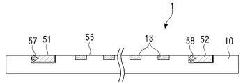
도 1은 본 발명의 일 실시예에 따른 퍼즐장치를 나타낸 사시도이다.
도 2는 본 발명의 일 실시예에 따른 퍼즐장치의 퍼즐판을 나타낸 사시도이다.
도 3은 도 2에 표시된 A-A선을 따라 나타낸 단면도이다.
도 4는 도 3에 도시된 퍼즐판의 후면에 배치된 지지대를 펼쳐 퍼즐판을 세워놓은 예를 나타낸 도면이다.
도 5는 본 발명의 일 실시예에 따른 퍼즐장치의 이격유닛을 나타낸 사시도이다.
도 6은 도 5에 도시된 제1 회전부재에 결합되는 제1 회전축을 나타낸 분해사시도이다.
도 7은 도 5에 도시된 제2 회전부재가 제2 회전축을 통해 퍼즐판에 회전 가능하게 연결된 예를 나타낸 도면이다.
도 8은 필름부재가 퍼즐판에 밀착된 예를 나타내는 도면이다.
도 9는 필름부재가 이격유닛에 의해 퍼즐판으로부터 이격된 예를 나타내는 도면이다.
도 10 내지 도 12는 필름부재가 제1 및 제2 회전부재로부터 분리 가능하게 결합될 수 있는 다양한 결합구조를 나타낸 도면들이다.
도 13은 이격유닛이 모터 구동으로 동작할 수 있는 예를 나타낸 도면이다.1 is a perspective view showing a puzzle device according to an embodiment of the present invention.
2 is a perspective view showing a puzzle plate of a puzzle device according to an embodiment of the present invention.
3 is a cross-sectional view taken along line AA shown in FIG. 2.
FIG. 4 is a view showing an example in which a puzzle board is erected by spreading a support placed on the rear surface of the puzzle board shown in FIG. 3.
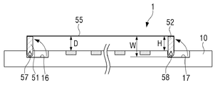
5 is a perspective view showing a separation unit of the puzzle device according to an embodiment of the present invention.
FIG. 6 is an exploded perspective view showing a first rotation axis coupled to the first rotation member shown in FIG. 5.
FIG. 7 is a view showing an example in which the second rotating member shown in FIG. 5 is rotatably connected to the puzzle board through the second rotating shaft.
8 is a view showing an example in which the film member is in close contact with the puzzle plate.
9 is a view showing an example in which the film member is separated from the puzzle plate by the separation unit.
10 to 12 are views showing various coupling structures in which the film member can be detachably coupled from the first and second rotating members.
13 is a view showing an example in which the separation unit can be operated by motor driving.
이하에서는 첨부된 도면을 참조하여 다양한 실시 예를 보다 상세하게 설명한다. 본 명세서에 기재된 실시 예는 다양하게 변형될 수 있다. 특정한 실시 예가 도면에서 묘사되고 상세한 설명에서 자세하게 설명될 수 있다. 그러나, 첨부된 도면에 개시된 특정한 실시 예는 다양한 실시 예를 쉽게 이해하도록 하기 위한 것일 뿐이다. 따라서, 첨부된 도면에 개시된 특정 실시 예에 의해 기술적 사상이 제한되는 것은 아니며, 발명의 사상 및 기술 범위에 포함되는 모든 균등물 또는 대체물을 포함하는 것으로 이해되어야 한다.Hereinafter, various embodiments will be described in detail with reference to the accompanying drawings. The embodiments described herein can be variously modified. Certain embodiments are depicted in the drawings and may be described in detail in the detailed description. However, the specific embodiments disclosed in the accompanying drawings are only for easy understanding of various embodiments. Therefore, the technical spirit is not limited by the specific embodiments disclosed in the accompanying drawings, and it should be understood that it includes all equivalents or substitutes included in the spirit and technical scope of the invention.
제1, 제2 등과 같이 서수를 포함하는 용어는 다양한 구성요소들을 설명하는데 사용될 수 있지만, 이러한 구성요소들은 상술한 용어에 의해 한정되지는 않는다. 상술한 용어는 하나의 구성요소를 다른 구성요소로부터 구별하는 목적으로만 사용된다.Terms including ordinal numbers such as first and second may be used to describe various components, but these components are not limited by the above-described terms. The above-mentioned terms are used only for the purpose of distinguishing one component from other components.
본 명세서에서, "포함한다" 또는 "가지다" 등의 용어는 명세서상에 기재된 특징, 숫자, 단계, 동작, 구성요소, 부품 또는 이들을 조합한 것이 존재함을 지정하려는 것이지, 하나 또는 그 이상의 다른 특징들이나 숫자, 단계, 동작, 구성요소, 부품 또는 이들을 조합한 것들의 존재 또는 부가 가능성을 미리 배제하지 않는 것으로 이해되어야 한다. 어떤 구성요소가 다른 구성요소에 "연결되어" 있다거나 "접속되어" 있다고 언급된 때에는, 그 다른 구성요소에 직접적으로 연결되어 있거나 또는 접속되어 있을 수도 있지만, 중간에 다른 구성요소가 존재할 수도 있다고 이해되어야 할 것이다.In this specification, terms such as “comprises” or “have” are intended to indicate that there are features, numbers, steps, operations, elements, parts, or combinations thereof described in the specification, and one or more other features. It should be understood that the existence or addition possibilities of fields or numbers, steps, operations, components, parts or combinations thereof are not excluded in advance. When an element is said to be "connected" or "connected" to another component, it is understood that other components may be directly connected to or connected to the other component, but there may be other components in between. It should be.
그 밖에 본 발명을 설명함에 있어서, 관련된 공지 기능 혹은 구성에 대한 구체적인 설명이 본 발명의 요지를 불필요하게 흐릴 수 있다고 판단되는 경우, 그에 대한 상세한 설명은 축약하거나 생략한다.In addition, in describing the present invention, when it is determined that detailed descriptions of related known functions or configurations may unnecessarily obscure the subject matter of the present invention, detailed descriptions thereof will be reduced or omitted.
이하, 도면을 참조하여, 퍼즐조각을 퍼즐판에 용이하게 탈부착할 수 있는 본 발명의 일 실시예에 따른 퍼즐장치를 상세히 설명한다.Hereinafter, a puzzle device according to an embodiment of the present invention capable of easily attaching and detaching a puzzle piece to a puzzle board will be described in detail with reference to the drawings.
도 1은 본 발명의 일 실시예에 따른 퍼즐장치를 나타낸 사시도이다.1 is a perspective view showing a puzzle device according to an embodiment of the present invention.
도 1을 참조하면, 본 발명의 일 실시예에 따른 퍼즐장치(1)는 경사진 상태로 세워 놓을 수 있는 퍼즐판(10)과, 자력에 의해 퍼즐판(10)에 부착되는 다수의 퍼즐조각(30)과, 퍼즐판(10)에 부착된 퍼즐조각(30)을 퍼즐판(10)으로부터 분리시키는 이격유닛(50)을 포함할 수 있다.Referring to Figure 1, the
이하, 도 2 내지 도 4를 참조하여, 퍼즐판(10)의 구조를 상세히 설명한다.Hereinafter, the structure of the
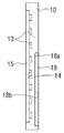
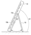
도 2는 본 발명의 일 실시예에 따른 퍼즐장치의 퍼즐판을 나타낸 사시도이고, 도 3은 도 2에 표시된 A-A선을 따라 나타낸 단면도이고, 도 4는 도 3에 도시된 퍼즐판의 후면에 배치된 지지대를 펼쳐 퍼즐판을 세워놓은 예를 나타낸 도면이다.Figure 2 is a perspective view showing a puzzle plate of a puzzle device according to an embodiment of the present invention, Figure 3 is a cross-sectional view taken along the AA line shown in Figure 2, Figure 4 is arranged on the back of the puzzle plate shown in Figure 3 It is an illustration showing an example of laying out a puzzle board with an open support.
도 2를 참조하면, 퍼즐판(10)은 소정의 두께를 가지는 사각형으로 이루어질 수 있다. 퍼즐판(10)의 형상은 사각형으로 한정될 필요는 없으며 다양한 형상으로 이루어질 수 있다.2, the
퍼즐판(10)의 전면에는 다수의 자석(13)이 일정한 간격을 두고 일부분이 각각 매립된 상태로 배열될 수 있다. 이 경우, 퍼즐판(10)에는 다수의 자석(13)이 각각 삽입되는 다수의 삽입홈(14)이 형성될 수 있다.A plurality of
다수의 자석(13)의 배열은 도 2와 같이 매트릭스로 배열될 수 있으나, 다수의 퍼즐조각(30)의 크기를 고려하여 적절한 크기와 배열을 이루는 것도 물론 가능하다.The arrangement of the plurality of
각 자석(13)은 버튼형 자석을 사용할 수 있으며, 바람직하게는 다수의 자석(13)이 퍼즐판(10)의 전면에 적절한 간격으로 배열될 수 있는 정도의 크기로 형성되면 족하다.Each
도 3을 참조하면, 퍼즐판(10)의 전면에는 다수의 자석(13)이 퍼즐판(10)의 다수의 삽입홈(14)으로부터 이탈하지 않도록 다수의 자석(13)을 덮는 커버(15)가 결합될 수 있다.Referring to Figure 3, the front of the
커버(15)는 다수의 자석(13)의 자력을 방해하지 않는 두께를 가지며 동시에 내구성을 고려하여 비자성체인 플라스틱 수지로 형성될 수 있다. 이 경우 커버(15)는 디자인을 고려하여 투명, 반투명 및 불투명 플라스틱 수지 중 어느 하나로 형성될 수 있다.The
도 2를 참조하면, 퍼즐판(10)은 전면에 이격유닛(50)의 일부를 이루는 제1 및 제2 회전부재(51,52, 도 5 참조)가 각각 회전 가능하게 삽입되는 제1 및 제2 장착홈(16,17)이 형성된다.Referring to FIG. 2, the
제1 장착홈(16)은 퍼즐판(10)의 좌측단에 인접하게 배치되고, 제2 장착홈(17)은 퍼즐판(10)의 우측단에 인접하게 배치될 수 있다. 제1 및 제2 장착홈(16,17)은 서로 평행하게 배치되는 것이 바람직하다.The first mounting
제1 장착홈(16)은 길이방향의 하단에 제1 축지지홈(16a)이 형성되고 길이방향의 상단에 관통구멍(16b)이 형성될 수 있다. 제1 축지지홈(16a)과 관통구멍(16b)에는 제1 회전부재(51)를 회전시키기 위한 제1 회전축(57, 도 6 참조)의 하단부(57a) 및 상단부(57b)가 각각 회전 가능하게 지지된다.The first mounting
제2 장착홈(17)은 길이방향의 하단과 상단에 각각 제2 및 제3 축지지홈(17a,17b)이 형성될 수 있다. 제2 및 제3 축지지홈(17a,17b)에는 제2 회전부재(52)를 회전시키기 위한 회전축(58, 도 7 참조)의 하단부(58a) 및 상단부(58b)가 각각 회전 가능하게 지지된다.The second mounting
도 3을 참조하면, 퍼즐판(10)의 후면에는 퍼즐판(10)을 소정 각도로 경사지게 세워 놓을 수 있는 지지대(18)가 구비될 수 있다.Referring to Figure 3, the back of the
도 4를 참조하면, 지지대(18)는 퍼즐판(10)의 후면에 형성된 수납홈(18b)에 삽입될 수 있으며, 퍼즐판(18)을 지지하기 위해 수납홈(18b)으로부터 제1 각도(θ1)로 펼쳐질 수 있다.Referring to FIG. 4, the
지지대(18)는 상단 양측에 각각 축돌기(18a)가 형성될 수 있다. 축돌기(18a)는 수납홈(18b)의 양측에 형성된 수용홈(미도시)에 회전 가능하게 결합될 수 있다.The
지지대(18)를 제1 각도(θ1)로 펼쳐서 퍼즐판(10)을 세우면, 퍼즐판(10)은 지면에 대하여 제2 각도(θ2)로 유지될 수 있다.If the
퍼즐판(10)을 지지대(18)에 의해 제2 각도(θ2)로 세우는 것은 퍼즐조각(30)이 이격유닛(50)에 의해 퍼즐판(10)으로부터 이격 시 자중에 의해 퍼즐조각(30)이 원활하게 흘러 내릴 수 있도록 하기 위함이다.Setting the
만약 퍼즐판(10)의 제2 각도(θ2)가 대략 30도 미만 정도로 너무 완만하게 설정되면, 이격유닛(50)에 의해 퍼즐판(10)으로부터 이격된 퍼즐조각(30)이 이격유닛(50)의 표면을 따라 원활하게 흘러 내려오지 않을 수 있다.If the second angle θ2 of the
따라서 제2 각도(θ2)는 퍼즐조각(30)이 이격유닛(50)에 의해 퍼즐판(10)으로부터 이격 시 자중에 의해 원활하게 흘러 내릴 수 있는 각도로 설정되는 것이 바람직하다. 이 경우, 지지대(18)가 세워질 때의 제2 각도(θ2)는 지지대(18)의 제1 각도(θ1)로 조절할 수 있다.Therefore, the second angle θ2 is preferably set to an angle at which the
도 1을 참조하면, 다수의 퍼즐조각(30)은 다수의 자석(13)의 자력에 의해 퍼즐판(10)에 부착될 수 있도록 자성체로 형성되는 것이 바람직하다. 다수의 퍼즐조각(30)은 통상적인 탱그램 퍼즐의 조각과 마찬가지로 서로 다른 위치로 배열할 경우 다양한 형상을 표현할 수 있다.Referring to Figure 1, the plurality of
이하, 도 5 내지 도 9를 참조하여, 이격유닛(50)이 구성 및 동작을 상세히 설명한다.Hereinafter, the configuration and operation of the
도 5는 본 발명의 일 실시예에 따른 퍼즐장치의 이격유닛을 나타낸 사시도이고, 도 6은 도 5에 도시된 제1 회전부재에 결합되는 제1 회전축을 나타낸 분해사시도이고, 도 7은 도 5에 도시된 제2 회전부재가 회전축을 통해 퍼즐판에 회전 가능하게 연결된 예를 나타낸 도면이고, 도 8은 필름부재가 퍼즐판에 밀착된 예를 나타내는 도면이고, 도 9는 필름부재가 이격유닛에 의해 퍼즐판으로부터 이격된 예를 나타내는 도면이다. 도 8 및 도 9에서 설명의 편의를 위해 퍼즐판(10)의 전면에 결합되는 커버(11)는 도시하지 않는다.5 is a perspective view showing a separation unit of the puzzle device according to an embodiment of the present invention, FIG. 6 is an exploded perspective view showing a first rotation axis coupled to the first rotating member shown in FIG. 5, FIG. 2 is a view showing an example in which the second rotating member is rotatably connected to the puzzle plate through the rotation axis, FIG. 8 is a diagram showing an example in which the film member is in close contact with the puzzle plate, and FIG. 9 is a film member in the separation unit It is a figure showing an example spaced apart from the puzzle board. For convenience of explanation in FIGS. 8 and 9, the cover 11 coupled to the front surface of the
이격유닛(50)은 다수의 자석(13)에 의해 퍼즐판(10)에 부착된 퍼즐조각(30)을 퍼즐판(10)으로부터 다수의 자력이 미치지 않는 거리만큼 강제로 이격시키는 수단이다.The
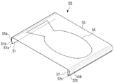
도 5를 참조하면, 이격수단(50)은 제1 및 제2 회전부재(51,52)와, 제1 및 제2 회전부재에 의해 퍼즐판(10)에 밀착되는 제1 위치와 퍼즐판(10)으로부터 일정한 간격으로 이격된 제2 위치로 이동하는 필름부재(55)를 포함할 수 있다.Referring to FIG. 5, the separation means 50 includes first and second
도 6을 참조하면, 제1 회전부재(51)는 제1 장착홈(16)에 회전 가능한 상태로 배치될 수 있도록, 제1 장착홈(16)의 길이보다 다소 작게 형성될 수 있다.Referring to FIG. 6, the first rotating
제1 회전부재(51)는 내측으로 제1 회전부재(51)의 길이방향을 따라 제1 회전축(57)이 결합되는 제1 결합구멍(51a)이 관통 형성될 수 있다.The first rotating
제1 회전부재(51)는 제1 회전축(57)을 회전에 따라 제1 회전축(57)과 함께 동일한 방향으로 회전한다. 이 경우 제1 회전축(57)은 제1 결합구멍(51a)에서 헛돌지 않도록 제1 결합구멍(51a)에 연통 형성된 키홈(51c)에 삽입되는 걸림돌기(57c)를 구비할 수 있다. 걸림돌기(57c)는 제1 회전축(57)의 길이방향을 따라 제1 회전축(57) 일주면에 형성된다.The first rotating
한편, 제1 회전축(57)이 제1 회전부재(51)의 제1 결합구멍(51a)에 압박 상태로 결합되게 구성될 수 있다. 이에 따라, 제1 회전축(57)의 외주면과 제1 결합구멍(51a)의 내주면 사이의 마찰력으로 인해 제1 회전축(57)이 제1 결합구멍(51a) 내에서 헛돌지 않고 제1 회전부재(51)가 함께 회전할 수 있다. 이와 같은 압박 결합구조를 채용하는 경우, 제1 회전축(57)의 걸림돌기(57c)와 키홈(51c)을 생략할 수 있다.Meanwhile, the
제1 회전축(57)은 전술한 바와 같이 하단부(57a)가 제1 장착홈(16)의 제1 축지지홈(16a)이 회전 가능하게 결합되고, 상단부(57b)가 제1 장착홈(16)의 관통구멍(16b)에 회전 가능하게 관통한다.As described above, the first
제1 회전축(57)은 상단부에 일측으로 절곡된 손잡이(57d)가 형성될 수 있다. 손잡이(57d)는 사용자가 필름부재(55)를 퍼즐판(10)으로부터 이격시키기 위해 제1 회전축(57)을 일방향으로 손쉽게 회전시킬 수 있도록 하는 구성이다.The
도 7을 참조하면, 제2 회전부재(52)는 제2 장착홈(17)에 회전 가능한 상태로 배치될 수 있도록, 제2 장착홈(17)의 길이보다 다소 작게 형성될 수 있다.Referring to FIG. 7, the second rotating
제2 회전부재(52)는 내측으로 제2 회전부재(52)의 길이방향을 따라 제2 회전축(58)이 결합되는 제2 결합구멍(52a)이 관통 형성될 수 있다.The second rotating
제2 회전부재(52)는 제2 회전축(58)과 함께 동일한 방향으로 회전한다. 이 경우 제2 회전축(58)이 제2 결합구멍(52a)에서 헛돌지 않도록 전술한 제1 회전부재(51)와 제1 회전축(57) 간의 헛돔 방지구조를 적용할 수 있다.The second rotating
따라서, 제2 회전부재(52)는 제1 회전부재(51)가 일방향으로 회전하면 필름부재(55)를 통해 제1 회전부재(51)의 회전력을 전달받는다. 이에 따라 제2 회전부재(52)는 제2 회전축(58)과 함께 제1 회전부재(51)의 회전 방향과 동일한 방향과 동일한 각도만큼 회전한다.Therefore, the second rotating
제2 회전축(58)은 전술한 바와 같이 하단부(58a) 및 상단부(58b)가 각각 제2 장착홈(17)의 제2 및 제3 축지지홈(17a,17b)이 회전 가능하게 결합될 수 있다. 이 경우 제2 회전축(58)은 하단부(58a) 및 상단부(58b)가 탄성부재에 의해 탄력적으로 연결될 수 있다.As described above, the
구체적으로, 상기 탄성부재는 제1 및 제2 토션스프링(59a,59b)일 수 있다. 제1 및 제2 토션스프링(59a,59b)은, 각각 일단이 제2 회전축(58)의 하단부(58a) 및 상단부(58b)에 연결되고, 각각 타단이 퍼즐판(10)의 내부에 연결될 수 있다.Specifically, the elastic member may be first and second torsion springs 59a and 59b. The first and second torsion springs (59a, 59b), one end is respectively connected to the lower end (58a) and the upper end (58b) of the second
제1 및 제2 토션스프링(59a,59b)은 제2 회전부재(52)를 제2 장착홈(17)에 삽입하는 방향으로 탄성력이 작용한다.The first and second torsion springs 59a and 59b exert an elastic force in a direction in which the second rotating
이에 따라, 사용자가 손잡이(57d)를 일방향으로 당기면 도 9와 같이 제1 및 제2 회전부재(51,52)가 제1 및 제2 장착홈(16,17)으로부터 돌출된다. 이 경우, 제1 및 제2 토션스프링(59a,59b)에 걸리는 탄성력을 증가하게 되며, 도 9의 상태에서 사용자가 손잡이(57d)를 놓으면 제1 및 제2 회전부재(51,52)는 제1 및 제2 토션스프링(59a,59b)의 탄성력에 의해 역방향으로 회전하여 도 8과 같이 제1 및 제2 장착홈(16,17)으로 삽입될 수 있다.Accordingly, when the user pulls the
도 9를 참조하면, 손잡이(57d)를 일방향으로 당겨 제1 및 제2 회전부재(51,52)가 회전하게 되면, 필름부재(55)는 퍼즐판(10)으로부터 일정 간격으로 이격되어 필름부재(55) 위에 놓은 다수의 퍼즐조각(30)은 다수의 자석(13)의 자력이 미치지 않는 위치로 이동된다.Referring to FIG. 9, when the first and second
이 경우, 필름부재(55)가 퍼즐판(10)으로부터 이격되는 거리(D)는 제1 및 제2 회전부재(51,52)가 제1 및 제2 장착홈(16,17)으로부터 돌출되는 높이(H)에 따라 결정될 수 있다. 또는 상기 이격 거리(D)는 제1 및 제2 회전부재(51,52)의 폭(W)에 따라 결정될 수 있다.In this case, the distance D at which the
도 5를 참조하면, 필름부재(55)는 제1 및 제2 회전부재(51,52)가 연동할 수 있도록, 필름부재(55)의 좌측단부(55a)와 우측단부(55b)가 각각 제1 및 제2 회전부재(51,52)에 연결된다. 이 경우, 필름부재(55)의 좌측단부(55a)와 우측단부(55b)는 각각 접착제를 통해 제1 및 제2 회전부재(51,52)에 부착될 수 있다.Referring to FIG. 5, the
필름부재(55)는 제1 및 제2 회전부재(51,52)의 회전을 동기화할 수 있도록 잘 늘어나지 않는 재질 예를 들면, OHP 필름의 재질과 동일한 재질로 제작될 수 있다. The
필름부재(55)는 일면에 다수의 퍼즐조각(30)이 놓이는 퍼즐영역(56)이 인쇄될 수 있다. 퍼즐영역(56)의 외곽은 특정한 형상을 나타낼 수 있다. 본 실시예에서는 퍼즐영역(56)의 외곽이 물고기를 나타낸다. 퍼즐영역(56)의 외곽 형상은 물고기에 한정하지 않고 다양한 것들의 외곽을 나타낼 수 있다.In the
이와 같이 구성된 본 발명의 일 실시예에 따른 퍼즐장치(1)의 동작을 설명한다.The operation of the
먼저 지지대를 이용하여 퍼즐장치(1)를 일정한 각도로 경사지게 세워 놓는다.First, the
이 경우 필름부재(55)는 도 8과 같이 퍼즐판(10)의 전면에 밀착 또는 인접한 제1 위치에 놓인다. 이 상태에서 필름부재(55)의 퍼즐영역(56)에 놓이는 다수의 퍼즐조각(30)은 안정적으로 부착된다.In this case, the
다수의 퍼즐조각(30)을 퍼즐영역(56)에 놓아 도 1과 같이 퍼즐을 완성한 후 다시 퍼즐을 시작하기 위해서 다수의 퍼즐조각(30)을 퍼즐판(10)으로부터 분리시킨다.After placing the plurality of
퍼즐판(10)으로부터 다수의 퍼즐조각(30)을 분리하기 위해, 손잡이(57d)를 파지하고 제1 회전축(57)을 일방향으로 대략 90도 정도 회전시킨다.In order to separate the plurality of
이에 따라 제1 및 제2 회전부재(51,52)가 일방향으로 회전하고 동시에 필름부재(55)는 퍼즐판(10)의 전면으로부터 소정 간격(D)으로 이격되어 제2 위치로 이동한다. Accordingly, the first and second
다수의 퍼즐조각(30)은 다수의 자석(13)의 자력이 미치는 영역으로부터 벗어나게 되면서 자중에 의해 필름부재(55)를 따라 흘러내린다. 이 경우, 도면에 도시하지 않았으나 흘러내린 다수의 퍼즐조각(30)을 수거하기 위한 트레이를 퍼즐장치(1)의 하측에 위치시킬 수 있다.The plurality of pieces of the
모든 퍼즐조각(30)이 아래로 흘러내린 상태에서, 손잡이(57d)를 놓으면 제1 및 제2 토션스프링(59a,59b)의 탄성력에 의해 제1 및 제2 회전부재(51,52)는 역방향으로 회전하여 원위치로 이동한다. 이와 동시에 필름부재(55)는 제2 위치로 이동하여 퍼즐판(10)의 전면에 접촉되거나 인접한 위치로 이동한다.When all the
이와 같이 본 발명은 퍼즐판(10)에 구비된 다수의 자석(13)을 통해 퍼즐조각(30)은 손쉽게 퍼즐판(10)에 부착할 수 있다. 또한 손잡이(57d)를 조작하는 단순한 동작을 통해 퍼즐판(10)으로부터 다수의 퍼즐조각(30)을 손쉽게 탈착 시킬 수 있다.As described above, the present invention can easily attach the
한편, 필름부재(55)는 제1 및 제2 회전부재(51,52)에 부착되는 것으로 설명하였으나, 이에 제한되지 않고 제1 및 제2 회전부재(51,52)에 분리 가능하게 연결될 수 있다.Meanwhile, the
이와 같이 필름부재(55)를 제1 및 제2 회전부재(51,52)로부터 분리 가능하도록 구성하는 경우, 퍼즐영역(56)의 형상이 서로 다른 다수의 필름부재를 선택적으로 교체하여 사용할 수 있다.In this way, when the
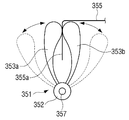
도 10 내지 도 12는 필름부재가 제1 및 제2 회전부재로부터 분리 가능하게 결합될 수 있는 다양한 결합구조를 나타낸 도면들이다.10 to 12 are views showing various coupling structures in which the film member can be detachably coupled from the first and second rotating members.
도 10을 참조하면, 제1 회전부재(151)의 일면에는 제1 벨크로 테이프(153)를 결합하고, 필름부재(155)의 좌측단부에는 제1 벨크로 테이프(153)에 분리 가능하게 부착되는 제2 벨크로 테이프(157)를 결합할 수 있다.Referring to FIG. 10, a
도면에 도시하지는 않았으나 제2 회전부재와 필름부재도 상호 벨크로 테이프에 의해 분리 가능하게 부착될 수 있다.Although not shown in the drawings, the second rotating member and the film member may also be detachably attached by mutual velcro tape.
도 11을 참조하면, 제1 회전부재(251)의 일면에는 다수의 결합돌기(253)가 간격을 두고 형성될 수 있다. 필름부재(255)의 좌측단부에는 제1 회전부재(251)의 다수의 결합돌기(253)가 각각 분리 가능하게 스냅 결합되는 다수의 결합구멍(257)이 간격을 두고 형성될 수 있다.Referring to FIG. 11, a plurality of engaging
도면에 도시하지는 않았으나 제2 회전부재와 필름부재도 결합돌기 및 결합구멍에 의해 상호 분리 가능하게 결합될 수 있다.Although not shown in the drawings, the second rotating member and the film member may also be detachably coupled to each other by engaging projections and engaging holes.
도 12을 참조하면, 제1 회전부재(351)는 제1 및 제2 부분(353a,353b)이 연결부(352)를 통해 상호 회전 가능하게 연결되는 집게 형상으로 이루어질 수 있다. 이 경우 연결부(352)에는 제1 및 제2 부분(353a,353b)이 서로 마주하는 방향으로 탄성력이 작용하는 토션스프링(미도시)이 설치되는 것이 바람직하다.Referring to FIG. 12, the first rotating
제1 회전부재(351)가 집게 형상으로 이루어짐에 따라, 필름부재(355)는 제1 회전부재와 연결하기 위한 별도의 연결구조를 구비할 필요 없다.As the first rotating
따라서, 필름부재(355)는 도 12와 같이 필름부재(355)의 좌측단부(355a)가 제1 및 제2 부분(353a,353b)에 의해 파지될 수 있다. 또한 필름부재(355)는 제1 및 제2 부분(353a,353b)을 벌려서 필름부재(355)의 좌측단부(355a)를 제1 회전부재(351)로부터 용이하게 분리할 수 있다. Accordingly, the
도면에 도시하지는 않았으나 제2 회전부재는 제1 회전부재와 동일하게 집게 형상으로 제작할 수 있다.Although not shown in the drawing, the second rotating member may be manufactured in the same shape as the first rotating member.
전술한 이격유닛(50)은 사용자가 손잡이(57d)를 사용하여 수동으로 작동한다. 하지만 이에 제한되지 않고, 모터 구동에 의해 이격유닛(50)을 제1 및 제2 위치로 동작시키는 것도 물론 가능하다.The above-described
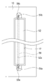
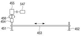
도 13은 이격유닛이 모터 구동으로 동작할 수 있는 예를 나타낸 도면이다.13 is a view showing an example in which the separation unit can be operated by motor driving.
제1 회전축(451)의 일단에 손잡이를 생략하고 커플러(454)를 통해 구동모터(455)의 구동축(456)과 연결한다. 구동모터(455)는 일정한 각도로 정회전 및 역회전하는 스텝핑 모터를 사용할 수 있다.The handle is omitted at one end of the first
제2 회전축(452)은 타이밍 벨트(453)를 통해 제1 회전축(451)의 회전력을 전달받을 수 있다. 이 경우 제1 및 제2 회전축(451,452)의 외주에는 타이밍 벨트(453)의 내주와 각각 기어 결합됨에 따라, 제1 및 제2 회전축(451,452)은 동시에 동일한 방향으로 회전할 수 있다.The
작동 스위치(547)는 구동모터(455)에 전기적으로 연결되어 구동모터(455)의 동작을 제어한다. 예를 들면, 작동 스위치(547)는 로터리 스위치를 사용할 수 있으며, 구동모터를 오프(off) 시키는 제1 모드와, 구동모터를 정회전 구동 시키는 제2 모드와, 구동모터를 역회전 구동 시키는 제3 모드 중 어느 하나로 설정할 수 있다.The
구동모터(455)와 작동 스위치(547)는 퍼즐판(10)의 일부분에 고정 배치될 수 있다.The driving
이상에서는 본 발명의 바람직한 실시 예에 대하여 도시하고 설명하였지만, 본 발명은 상술한 특정의 실시 예에 한정되지 아니하며, 청구범위에서 청구하는 본 발명의 요지를 벗어남이 없이 당해 발명이 속하는 기술분야에서 통상의 지식을 가진 자에 의해 다양한 변형실시가 가능한 것은 물론이고, 이러한 변형실시들은 본 발명의 기술적 사상이나 전망으로부터 개별적으로 이해되서는 안될 것이다.In the above, although the preferred embodiment of the present invention has been illustrated and described, the present invention is not limited to the above-described specific embodiment, and is generally in the technical field to which the present invention belongs without departing from the gist of the present invention claimed in the claims It is of course possible to perform various modifications by a person having knowledge of, and these modifications should not be individually understood from the technical idea or prospect of the present invention.
10: 퍼즐판
13: 자석
16: 제1 장착홈
17: 제2 장착홈
18: 지지대
30: 퍼즐조각
50: 이격유닛
51: 제1 회전부재
52: 제2 회전부재
55: 필름부재
57: 제1 회전축
58: 제2 회전축10: puzzle board 13: magnet
16: First mounting groove 17: Second mounting groove
18: Support 30: Puzzle Piece
50: separation unit 51: first rotating member
52: second rotating member 55: film member
57: first rotating shaft 58: second rotating shaft
Claims (10)
일면에 다수의 자석이 배열된 퍼즐판; 및
상기 다수의 퍼즐조각을 상기 다수의 자석의 자력에 의해 상기 퍼즐판에 부착시키는 제1 위치와 상기 다수의 퍼즐조각을 상기 다수의 자석의 자력이 미치지 않는 제2 위치 중 어느 하나의 위치로 이동하는 이격유닛;을 포함하는 것을 특징으로 하는 퍼즐장치.A number of puzzle pieces made of magnetic material;
A puzzle plate in which a plurality of magnets are arranged on one side; And
Moving the plurality of pieces of the puzzle to one of the first position of attaching the pieces of the puzzle to the puzzle board by the magnetic force of the plurality of magnets and the second position of the plurality of pieces of the puzzle not affected by the magnetic force of the plurality of magnets Separation unit; puzzle device comprising a.
상기 이격유닛은,
상기 퍼즐판의 일측에 회전 가능하게 배치된 제1 회전부재;
상기 퍼즐판의 타측에 회전 가능하게 배치된 제 2회전부재; 및
상기 제1 및 제2 회전부재의 회전을 동기화하도록 양단이 각각 상기 제1 및 제2 회전부재에 연결된 필름부재;를 포함하는 것을 특징으로 하는 퍼즐장치.According to claim 1,
The separation unit,
A first rotating member rotatably disposed on one side of the puzzle plate;
A second rotating member rotatably disposed on the other side of the puzzle plate; And
And a film member having both ends connected to the first and second rotating members to synchronize rotation of the first and second rotating members, respectively.
상기 제1 회전부재는 제1 회전축에 의해 상기 퍼즐판에 회전 가능하게 연결되며,
상기 제2 회전부재는 상기 제1 회전축과 평행하게 배치된 제2 회전축에 의해 상기 퍼즐판에 회전 가능하게 연결된 것을 특징으로 하는 퍼즐장치.According to claim 2,
The first rotating member is rotatably connected to the puzzle plate by a first rotating shaft,
The second rotating member is a puzzle device, characterized in that rotatably connected to the puzzle plate by a second rotating shaft disposed parallel to the first rotating shaft.
상기 제1 회전축은 일단에 손잡이를 구비한 것을 특징으로 하는 퍼즐장치.According to claim 3,
The first rotating shaft puzzle device, characterized in that provided with a handle at one end.
상기 제2 회전부재는 양단에 설치된 제1 및 제2 토션스프링이 설치되며 상기 필름부재를 상기 제1 위치로 이동하는 방향으로 탄성력이 작용하는 것을 특징으로 하는 퍼즐장치.The method of claim 3 or 4,
The second rotating member has first and second torsion springs installed at both ends, and a puzzle device characterized in that an elastic force acts in a direction to move the film member to the first position.
상기 제1 및 제2 회전부재는,
상기 제1 위치에서 상기 퍼즐판에 형성된 제1 및 제2 장착홈에 각각 삽입되며, 상기 제2 위치에서 상기 제1 및 제2 장착홈으로부터 돌출되는 것을 특징으로 하는 퍼즐장치.According to claim 1,
The first and second rotating members,
The first and second mounting grooves respectively formed in the puzzle plate in the first position, characterized in that protruding from the first and second mounting grooves in the second position puzzle device.
상기 퍼즐판은 상기 다수의 자석을 덮도록 상기 퍼즐판의 일면에 배치된 비자성체인 커버를 더 포함하는 것을 특징으로 하는 퍼즐장치.According to claim 1,
The puzzle plate is a puzzle device, characterized in that it further comprises a non-magnetic chain cover disposed on one surface of the puzzle plate to cover the plurality of magnets.
상기 필름부재는 양단부가 상기 제1 및 제2 회전부재에 각각 부착된 것을 특징으로 하는 퍼즐장치.According to claim 2,
The film member is a puzzle device, characterized in that both ends are attached to the first and second rotating members, respectively.
상기 필름부재는 양단부가 각각 상기 제1 및 제2 회전부재에 분리 가능하게 연결된 것을 특징으로 하는 퍼즐장치.According to claim 2,
The film member is a puzzle device, characterized in that both ends are detachably connected to the first and second rotating members, respectively.
상기 제1 회전축을 정방향 및 역방향으로 회전하기 위한 구동모터;
상기 제1 회전축의 회전력을 상기 제2 회전축으로 전달하기 위해, 상기 제1 및 제2 회전축을 상호 연결한 타이밍 벨트; 및
상기 구동모터의 오프(off) 모드, 정방향 회전 모드 및 역방향 회전 모드 중 어느 하나의 모드로 설정하는 작동 스위치;를 포함하는 것을 특징으로 하는 퍼즐장치.According to claim 3,
A drive motor for rotating the first rotation axis in the forward and reverse directions;
A timing belt interconnecting the first and second rotation axes to transmit the rotational force of the first rotation axis to the second rotation axis; And
A puzzle device comprising a; operation switch for setting to any one of the off (off) mode, the forward rotation mode and the reverse rotation mode of the drive motor.
Priority Applications (1)
| Application Number | Priority Date | Filing Date | Title |
|---|---|---|---|
| KR1020190011542A KR102155666B1 (en) | 2019-01-30 | 2019-01-30 | Puzzle apparatus |
Applications Claiming Priority (1)
| Application Number | Priority Date | Filing Date | Title |
|---|---|---|---|
| KR1020190011542A KR102155666B1 (en) | 2019-01-30 | 2019-01-30 | Puzzle apparatus |
Publications (2)
| Publication Number | Publication Date |
|---|---|
| KR20200094271A true KR20200094271A (en) | 2020-08-07 |
| KR102155666B1 KR102155666B1 (en) | 2020-09-14 |
Family
ID=72050011
Family Applications (1)
| Application Number | Title | Priority Date | Filing Date |
|---|---|---|---|
| KR1020190011542A Active KR102155666B1 (en) | 2019-01-30 | 2019-01-30 | Puzzle apparatus |
Country Status (1)
| Country | Link |
|---|---|
| KR (1) | KR102155666B1 (en) |
Families Citing this family (1)
| Publication number | Priority date | Publication date | Assignee | Title |
|---|---|---|---|---|
| KR102599316B1 (en) | 2022-01-25 | 2023-11-06 | 홍수진 | A puzzle-type mother-of-pearl craft kit |
Citations (2)
| Publication number | Priority date | Publication date | Assignee | Title |
|---|---|---|---|---|
| JPH09234267A (en) * | 1996-02-29 | 1997-09-09 | Seikosha Co Ltd | Magnetic puzzle apparatus |
| KR20120000981U (en) * | 2010-07-30 | 2012-02-09 | 김덕용 | Puzzle assembly |
-
2019
- 2019-01-30 KR KR1020190011542A patent/KR102155666B1/en active Active
Patent Citations (2)
| Publication number | Priority date | Publication date | Assignee | Title |
|---|---|---|---|---|
| JPH09234267A (en) * | 1996-02-29 | 1997-09-09 | Seikosha Co Ltd | Magnetic puzzle apparatus |
| KR20120000981U (en) * | 2010-07-30 | 2012-02-09 | 김덕용 | Puzzle assembly |
Also Published As
| Publication number | Publication date |
|---|---|
| KR102155666B1 (en) | 2020-09-14 |
Similar Documents
| Publication | Publication Date | Title |
|---|---|---|
| EP4257213B1 (en) | Magic cube with visible magnetic cabins | |
| KR101447679B1 (en) | Assembling block toy | |
| KR20200094271A (en) | Puzzle apparatus | |
| EP3493885B1 (en) | Board game | |
| CN218420993U (en) | Peg-top toy emitter | |
| KR101385989B1 (en) | Assembling block toy | |
| US20140199677A1 (en) | Modular Multi-Element Constructions From Rearrangeable Pieces And Kits Allowing Construction Of Same | |
| EP3210661B1 (en) | Magnetically connected toy block | |
| US7025351B2 (en) | Puzzle game | |
| US6537123B2 (en) | System and method for displaying magnetic devices | |
| CN212141429U (en) | Three-order magnetic magic cube with stable and wear-resistant structure | |
| US4674988A (en) | Twirling break-dancing toy device | |
| KR200471717Y1 (en) | Opperation bar for toy of the block is formed a various prining sheet | |
| CA3126501A1 (en) | Device for sports training | |
| US10729969B2 (en) | Customizable playing cards with interchangeable components | |
| KR20190068166A (en) | RC controller | |
| CN109715257B (en) | Assembled module | |
| CN216456846U (en) | Magic cube with center block convenient to disassemble and assemble | |
| CN223127209U (en) | Novel balanced game toy | |
| CN211273560U (en) | Hand-driven disc | |
| CN219758644U (en) | Hand projector | |
| KR101635314B1 (en) | Wearable watch type toy | |
| CN217854490U (en) | Sliding jigsaw puzzle | |
| CN219267233U (en) | Arc-shaped LED display screen | |
| CN214165784U (en) | Rotary structure type shoe box |
Legal Events
| Date | Code | Title | Description |
|---|---|---|---|
| PA0109 | Patent application |
St.27 status event code: A-0-1-A10-A12-nap-PA0109 |
|
| PA0201 | Request for examination |
St.27 status event code: A-1-2-D10-D11-exm-PA0201 |
|
| R18-X000 | Changes to party contact information recorded |
St.27 status event code: A-3-3-R10-R18-oth-X000 |
|
| R18-X000 | Changes to party contact information recorded |
St.27 status event code: A-3-3-R10-R18-oth-X000 |
|
| D13-X000 | Search requested |
St.27 status event code: A-1-2-D10-D13-srh-X000 |
|
| D14-X000 | Search report completed |
St.27 status event code: A-1-2-D10-D14-srh-X000 |
|
| R18-X000 | Changes to party contact information recorded |
St.27 status event code: A-3-3-R10-R18-oth-X000 |
|
| PE0902 | Notice of grounds for rejection |
St.27 status event code: A-1-2-D10-D21-exm-PE0902 |
|
| E13-X000 | Pre-grant limitation requested |
St.27 status event code: A-2-3-E10-E13-lim-X000 |
|
| P11-X000 | Amendment of application requested |
St.27 status event code: A-2-2-P10-P11-nap-X000 |
|
| P13-X000 | Application amended |
St.27 status event code: A-2-2-P10-P13-nap-X000 |
|
| R18-X000 | Changes to party contact information recorded |
St.27 status event code: A-3-3-R10-R18-oth-X000 |
|
| PG1501 | Laying open of application |
St.27 status event code: A-1-1-Q10-Q12-nap-PG1501 |
|
| E701 | Decision to grant or registration of patent right | ||
| PE0701 | Decision of registration |
St.27 status event code: A-1-2-D10-D22-exm-PE0701 |
|
| GRNT | Written decision to grant | ||
| PR0701 | Registration of establishment |
St.27 status event code: A-2-4-F10-F11-exm-PR0701 |
|
| PR1002 | Payment of registration fee |
St.27 status event code: A-2-2-U10-U11-oth-PR1002 Fee payment year number: 1 |
|
| PG1601 | Publication of registration |
St.27 status event code: A-4-4-Q10-Q13-nap-PG1601 |
|
| PN2301 | Change of applicant |
St.27 status event code: A-5-5-R10-R13-asn-PN2301 St.27 status event code: A-5-5-R10-R11-asn-PN2301 |
|
| R18-X000 | Changes to party contact information recorded |
St.27 status event code: A-5-5-R10-R18-oth-X000 |
|
| PR1001 | Payment of annual fee |
St.27 status event code: A-4-4-U10-U11-oth-PR1001 Fee payment year number: 4 |
|
| PR1001 | Payment of annual fee |
St.27 status event code: A-4-4-U10-U11-oth-PR1001 Fee payment year number: 5 |
|
| R18 | Changes to party contact information recorded |
Free format text: ST27 STATUS EVENT CODE: A-5-5-R10-R18-OTH-X000 (AS PROVIDED BY THE NATIONAL OFFICE) |
|
| R18-X000 | Changes to party contact information recorded |
St.27 status event code: A-5-5-R10-R18-oth-X000 |
|
| R18 | Changes to party contact information recorded |
Free format text: ST27 STATUS EVENT CODE: A-5-5-R10-R18-OTH-X000 (AS PROVIDED BY THE NATIONAL OFFICE) |
|
| R18-X000 | Changes to party contact information recorded |
St.27 status event code: A-5-5-R10-R18-oth-X000 |