KR20200090485A - Slope road paving rollers with auxiliary wheels - Google Patents
Slope road paving rollers with auxiliary wheels Download PDFInfo
- Publication number
- KR20200090485A KR20200090485A KR1020190007569A KR20190007569A KR20200090485A KR 20200090485 A KR20200090485 A KR 20200090485A KR 1020190007569 A KR1020190007569 A KR 1020190007569A KR 20190007569 A KR20190007569 A KR 20190007569A KR 20200090485 A KR20200090485 A KR 20200090485A
- Authority
- KR
- South Korea
- Prior art keywords
- roller
- roller equipment
- frame
- auxiliary wheel
- road
- Prior art date
Links
Images


Classifications
-
- E—FIXED CONSTRUCTIONS
- E01—CONSTRUCTION OF ROADS, RAILWAYS, OR BRIDGES
- E01C—CONSTRUCTION OF, OR SURFACES FOR, ROADS, SPORTS GROUNDS, OR THE LIKE; MACHINES OR AUXILIARY TOOLS FOR CONSTRUCTION OR REPAIR
- E01C19/00—Machines, tools or auxiliary devices for preparing or distributing paving materials, for working the placed materials, or for forming, consolidating, or finishing the paving
- E01C19/22—Machines, tools or auxiliary devices for preparing or distributing paving materials, for working the placed materials, or for forming, consolidating, or finishing the paving for consolidating or finishing laid-down unset materials
- E01C19/23—Rollers therefor; Such rollers usable also for compacting soil
- E01C19/231—Rollers therefor; Such rollers usable also for compacting soil with both elastically-deformable and rigid rolling elements, e.g. pneumatic-tyred compactor with selectively operative or inoperative steel-faced roll
-
- E—FIXED CONSTRUCTIONS
- E01—CONSTRUCTION OF ROADS, RAILWAYS, OR BRIDGES
- E01C—CONSTRUCTION OF, OR SURFACES FOR, ROADS, SPORTS GROUNDS, OR THE LIKE; MACHINES OR AUXILIARY TOOLS FOR CONSTRUCTION OR REPAIR
- E01C19/00—Machines, tools or auxiliary devices for preparing or distributing paving materials, for working the placed materials, or for forming, consolidating, or finishing the paving
- E01C19/22—Machines, tools or auxiliary devices for preparing or distributing paving materials, for working the placed materials, or for forming, consolidating, or finishing the paving for consolidating or finishing laid-down unset materials
- E01C19/23—Rollers therefor; Such rollers usable also for compacting soil
- E01C19/236—Construction of the rolling elements, e.g. surface configuration, rolling surface formed by endless track
Abstract
Description
본 발명은 일반도로와 달리 높은 경사면을 가지고, 작은 반경에서 고속으로 회전을 하는 고속주회로 등의 도로를 포장할 때 다짐장비인 롤러가 경사에 의하여 전도되거나 미끄러짐을 방지하고, 롤러장비의 무게중심이 경사면 하방면으로 쏠려 일정한 다짐면의 생성이 어려운 문제점을 해결하는 것으로 상기 문제점들을 해결하기 위하여 롤러의 측방향으로 별도의 보조바퀴를 부착한 보조바퀴부가 포함된 경사면 도로포장 롤러장비에 관한 것이다.The present invention, unlike a general road, has a high inclined surface, and when paving roads such as a high-speed main circuit that rotates at a high speed at a small radius, the compaction equipment prevents the rollers from falling or slipping due to inclination, and the center of gravity of the roller equipment The present invention relates to an inclined road pavement roller equipment including an auxiliary wheel portion in which a separate auxiliary wheel is attached in the lateral direction of the roller to solve the above problems by solving the problem that it is difficult to generate a certain compaction surface by being inclined toward the lower surface.
일반적으로 도로는 일반인의 교통 및 물자수송 등 이용자가 편리하게 목적지까지 도달할 수 있도록 제공되는 시설로 국내 자동차의 등록 대수가 증가되는 추세에 따라서 도로에 투자되는 국가 예산도 지속적으로 증가 되고 있으며, 이중 도로 포장에 투입되는 비용은 약 20~30%이고, 지자체나 민간건설에서 투입되는 도로포장 비용까지 포함하게 되면 더 많은 비용이 도로포장에 투자 되고 있는 실정이다.In general, roads are facilities provided to allow users to reach their destinations conveniently, such as transportation and goods transportation for the general public. As the number of registered domestic cars increases, the national budget for investment in roads continues to increase. The cost for road pavement is about 20~30%. If the road pavement cost from local governments or private construction is included, more costs are invested in road pavement.
도로는 지반 상부로 성토, 보조기층, 기층 및 표층으로 이루어져 있고, 상기 표층이 차도에 해당되며, 각층별로 정해진 기준에 따라 적층이 실시되고, 이와 같은 일련의 순서로 도로포장을 시공하고 있다. 한편, 도로포장에서 최종적으로 표층을 이루는 아스팔트 작업시 아스팔트를 포설하고 피니셔 작업 후 다짐작업을 실시하고 있으며, 다짐작업은 8톤 이상의 머캐덤 롤러와 6톤 이상의 2축식 탄뎀롤러 및 10톤 이상의 타이어 롤러를 사용하여 하며, 규격과 종류 및 다짐 횟수는 시험 포장 결과에 따라 결정하고 있다.The road is composed of fill, sub-base, base and surface layers on the ground, and the surface layer corresponds to a roadway, and the lamination is carried out according to the standards set for each floor, and the road pavement is constructed in this sequence. On the other hand, when the asphalt work that finally forms the surface layer on the road pavement, asphalt is laid, and after the finisher work, compaction is carried out, and the compaction work includes 8 ton or more macadam roller, 6 ton or more biaxial tandem roller and 10 ton or more tire roller. It is used, and the specification, type, and number of compactions are determined according to the test packaging results.
한편, 도로 정면에서 좌우측이 경사를 가지는 고속주회로 등의 도로포장 다짐 시공시 롤러장비의 롤러에 의한 다짐은 종단방향에 따라 낮은 쪽에서 높은 쪽으로 향하여 차츰 폭을 옮기며 다지고 있으나 위와 같이 도로의 횡방향으로 경사를 이루는 도로는 종단방향으로 롤러장비를 이용할 경우 롤러장비의 무게중심이 하방으로 이동되어 지면과 접촉되는 롤러의 상방영역의 다짐밀도가 적어지고, 롤러장비가 경사면 하방으로 전도되거나 미끄러지는 문제가 발생하여 횡단방향으로 다짐하기 어려워 수동식 탬퍼를 이용하여 다지고 있지만 다짐 밀도가 약하고, 다짐시공에 드는 시간이 오래 걸린다는 단점을 가지고 있다. 따라서, 다짐 밀도가 약해져 도로가 패이는 포트홀이 발생될 가능성이 높아져 도로 이용자의 안전성이 떨어지고, 오랜 시공에 따른 시공비용이 높아진다는 문제점이 발생되고 있다.On the other hand, compaction by rollers of roller equipment during construction of pavement pavement, such as a high-speed main circuit in which the left and right sides are inclined from the front of the road, is gradually moving from low to high in accordance with the longitudinal direction. When using the roller equipment in the longitudinal direction of the slope, the weight center of the roller equipment is moved downward to reduce compaction density in the upper area of the roller that comes into contact with the ground, and there is a problem that the roller equipment falls or slips down the slope. Although it is difficult to compact in the transverse direction, it is compacted using a manual tamper, but has a disadvantage that the compaction density is weak and it takes a long time for compaction construction. Accordingly, there is a problem in that the compaction density becomes weak, so that the possibility of a porthole digging the road increases, resulting in a decrease in safety for road users and a high construction cost due to long construction.
경사를 이루는 도로의 다짐 공정에 의해서 발생되는 문제점을 해결하기 위한 선행기술들로는 한국공개특허 제10-2008-0112642호(2008.12.26.) 이동수단과; 상기 이동수단의 상부에 배치되어 드럼과, 상기 드럼을 안내하는 이동바, 및 상기 드럼을 회전시키는 드럼회전수단을 지지하는 고정부와; 상기 드럼에 일단이 고정된 연결수단의 타단에 연결된 롤러;를 포함하는 경사면 다짐장치가 제공되고, 한국등록실용신안 제20-0291916호(2002.10.11.) 비탈면 다짐 작업을 실시하는 진동부재와 상기 진동부재를 이동시키는 이동 트럭으로 이루어진 도로 비탈면 다짐을 위한 유압진동 다짐장비를 제공하고 있다.Prior art for solving the problems caused by the compaction process of the road forming the slope include Korean Patent Publication No. 10-2008-0112642 (2008.12.26.) moving means; A fixing part disposed on an upper portion of the moving means to support a drum, a moving bar for guiding the drum, and a drum rotating means for rotating the drum; A roller connected to the other end of the connecting means having one end fixed to the drum; an inclined surface compaction device is provided, and the Korean Registered Utility Model No. 20-0291916 (2002.10.11.) vibrating member for performing compaction work It provides hydraulic vibration compaction equipment for compacting road slopes made of moving trucks that move vibrating members.
그러나 상기 선행기술들은 종래 문제점인 시공에 드는 시간의 절감을 이루지 못하였고, 다짐 시공되는 전체 면적에 동일한 다짐 강도를 주기 어려우며, 높은 다짐 밀도를 구현하기 어렵고, 다짐에 사용되는 장비의 구성이 복잡하며, 장비를 준비하는 비용이 더 든다는 점에서 실질적이 해결책이 되지 못한다.However, the above prior arts did not achieve a reduction in time required for construction, which is a conventional problem, it is difficult to give the same compaction strength to the entire area to be compacted, it is difficult to implement a high compaction density, and the configuration of equipment used for compaction is complicated. However, it is not a practical solution in that it costs more to prepare equipment.
본 발명이 이루고자 하는 기술적 과제는 상기와 같은 종래 일반적인 기술 및 선행기술들에서 횡방향으로 경사도를 이루는 고속주회로 등의 도로를 포장시공에서 롤러장비를 이용한 포장시 롤러장비의 전도 및 미끄러지는 문제를 해결하고, 경사도에 따라서 롤러가 가하는 힘이 롤러전체에 균등하게 주어 다짐되는 위치의 다짐밀도를 높이며, 다짐시공 기간과 비용을 절감하는 보조바퀴부가 포함된 경사면 도로 포장 롤러장비를 제공하는 것이다.The technical problem to be achieved by the present invention is to solve the problem of slipping and slipping of the roller equipment when paving the road such as a high-speed main circuit that forms a slope in the transverse direction in the conventional general technology and prior art as described above. It is to provide an inclined road pavement roller equipment including an auxiliary wheel portion that solves, increases the compaction density at a compacted position by applying the force applied by the rollers evenly to the entire roller according to the inclination, and reduces compaction construction period and cost.
상기와 같은 문제점을 해결하고, 목적을 달성하기 위하여 본 발명의 일 실시예에 따른 보조바퀴부가 포함된 경사면 도로 포장 롤러장비는 롤러가 부착 설치되어 도로 포장시 지면을 다짐하는 작업을 실시하는 롤러장비(A); 및In order to solve the above problems and achieve the object, the road pavement roller equipment including an auxiliary wheel according to an embodiment of the present invention is equipped with a roller and roller equipment is installed to compact the ground when paving the road. (A); And
상기 롤러장비의 측면에 연결 부착설치되되 경사면의 하방영역에 위치되어 롤러장비의 전도방지 및 미끄럼 방지를 실시하는 보조바퀴부(B);를 포함한다.It includes; attached to the side of the roller equipment is installed, but is located in the lower area of the inclined surface, the auxiliary wheel portion (B) to prevent the fall and slip of the roller equipment.
상기 롤러장비(A)는 머캐덤롤러, 탬덤롤러 및 타이어롤러 중 선택된 하나 이상을 사용하며, 보조바퀴부(B)가 사용되는 롤러장비에 탈부착하여 사용된다.The roller equipment (A) uses one or more selected from a macadam roller, a tadam roller, and a tire roller, and is used by attaching and detaching to the roller equipment where the auxiliary wheel portion (B) is used.
상기 보조바퀴부(B)는 고정대(12)를 이용하여 롤러장비(A) 일측에 부착 설치되는 "ㄴ"자 형상의 고정프레임(10), 상기 고정프레임(10) 하부 끝단에 힌지(22)로 연결되어 유동되는 유동프레임(20), 상기 고정프레임(10)과 유동프레임(20)의 마주보는 면에 양 측면이 부착되어 설치되는 유압수단(30), 상기 유압수단(30)이 설치된 반대면에 부착 설치되어 길이가 조절되는 접철식 프레임(40), 상기 접철식 프레임(40)으로 연결되는 수직프레임(50), "∩"형상으로 상부면에 상기 수직프레임(50) 하부끝단이 고정 설치된 보조프레임(60) 및 상기 보조프레임(60)의 하부 끝단에 바퀴축이 구비되어 중앙을 통해 설치되는 보조바퀴(70)를 포함한다.The auxiliary wheel portion (B) is fixed to the roller frame (A) by using a fixture (12) attached to one side of the "b" shaped fixed frame (10), the fixed frame (10) hinge (22) at the lower end Connected to the
상기 고정프레임(10)은 롤러장비(A) 방향 하부 일측면에 롤러장비(A)의 하부면과 양측면에 고정설치되어 보조바퀴부(B)와 롤러장비(A)의 결합력을 높이는 "∪" 형상의 결착프레임(14)이 부착 설치된다.The
상기 유압수단(30)은 마주보는 원판(34) 사이에 유압파이프(36)와 코일스프링(38)이 구성되고, 유압파이프(36) 일단은 롤러장비(A)에 설치된 유압장치(미도시)를 이용하여 유압을 가하는 유압호스(32)가 연결설치되어 유압수단(30)의 길이조절이 가능하며, 유압수단(30)의 길이에 따라 유동프레임(20)의 각도가 조절된다.The
상기 보조바퀴부(B)는 롤러장비(A)를 이용한 경사면 도로 포장 다짐시 경사면의 각도에 따라 접철식 프레임(40)의 길이를 조절하고, 유압수단(30)을 이용하여 유동프레임(20)을 일정 각도로 조절시켜 롤러장비(A)를 경사면 하방에서 상방으로 지지해 주어 경사면에 위치된 롤러장비(A)의 무게중심 변화를 방지시킴으로써 롤러장비(A)의 전도 및 미끄럼을 방지하고, 수직항력이 롤러 전체에 균등하게 준다.The auxiliary wheel part (B) adjusts the length of the
상기 접철식 프레임(40)은 내방으로 공간이 형성되어 있고, 상기 공간에 유동프레임(20)과 수직프레임(50)에 접철식 파이프(42)로 연결 설치되어 롤러장비(A) 무게에 의한 접철식 프레임(40)의 파손을 방지하고, 결합력을 높이며, 상기 접철식 파이프(42)는 길이 조절이 가능하다.The
상기 롤러장비(A)는 롤러와 일직선상의 상부면에 회동되는 벨트(80)가 설치되어 벨트(80) 상부면에 추(82)를 설치하여 경사면에 따라 추(82)를 좌측 또는 우측으로 이동시켜 추가적으로 무게중심을 변화시키거나 기계식 또는 유압식을 이용한 높이조절 쇼바를 이용하여 경사면에서 롤러의 상방에 위치한 롤러장비가 수평을 이룰 수 있는 보조바퀴부가 포함된 경사면 도로 포장 롤러장비를 제공한다.The roller equipment (A) is provided with a
이상에서 설명한 바와 같이 본 발명에 의한 보조바퀴부가 포함된 경사면 도로 포장 롤러장비는 다음과 같은 효과가 있다.As described above, the road pavement roller equipment including the auxiliary wheel according to the present invention has the following effects.
(1) 본 발명은 고속주회로 등의 경사를 가지는 도로의 다짐시공시 보조바퀴에 의해서 롤러장비의 전도 및 미끄러지는 문제점과 롤러장비의 무게중심 변화를 방지하여 롤러가 다짐하는 면적에 동일한 힘을 가할 수 있다.(1) The present invention prevents the problem of falling and slipping of roller equipment and the change in the center of gravity of the roller equipment by the auxiliary wheel during compaction of roads with a slope such as a high-speed main circuit, and applies the same force to the area where the roller compacts. Can be applied.
(2) 본 발명은 경사면 도로의 다짐이 균일하게 적용되어 도로 수명을 높여 도로 이용자의 안전을 보장하고, 불필요한 보수공사를 미연에 방지된다.(2) According to the present invention, compaction of a road on an inclined surface is uniformly applied to increase road life to ensure the safety of road users and prevent unnecessary repair work.
(3) 본 발명은 경사면 도로의 다짐 공정을 부피가 큰 롤러 및 다짐 설비가 필요없고, 종방향 줄눈부 발생을 방지할 수 있으므로 공사 시간을 절약하고, 도로포장에 드는 비용을 절감시킨다.(3) The present invention does not require bulky rollers and compaction equipment for the compaction process of the inclined road, and can prevent the occurrence of longitudinal joints, thereby saving construction time and reducing the cost of road pavement.
도 1은 본 발명의 바람직한 일 실시예에 따른 보조바퀴부가 포함된 경사면 도로 포장 롤러장비의 정면도이다.
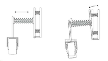
도 2는 본 발명의 바람직한 일 실시예에 따른 접척식 프레임의 길이 조절 및 유동프레임의 유동을 보여주는 예시도이다.
도 3은 본 발명의 바람직한 일 실시예에 따른 유압수단의 사시도이다.
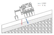
도 4는 본 발명의 바람직한 일 실시예에 따른 보조바퀴부가 포함된 경사면 도로 포장 롤러장비의 사용 예시도이다.
도 5는 본 발명의 바람직한 일 실시예에 따른 추 및 벨트가 추간된 보조바퀴부가 포함된 경사면 도로 포장 롤러장비의 평면도이다.1 is a front view of an inclined road pavement roller equipment including an auxiliary wheel according to an exemplary embodiment of the present invention.
2 is an exemplary view showing the length of the collapsible frame and the flow of the flow frame according to a preferred embodiment of the present invention.
3 is a perspective view of a hydraulic means according to a preferred embodiment of the present invention.
Figure 4 is an exemplary view of the use of the pavement roller equipment on the slope road including the auxiliary wheel according to an embodiment of the present invention.
5 is a plan view of a pavement roller equipment on a sloped road including an auxiliary wheel portion in which a weight and a belt are interpolated according to a preferred embodiment of the present invention.
본 발명의 명칭은 "보조바퀴부가 포함된 경사면 도로 포장 롤러장비"로 통상의 기술자가 쉽게 알 수 있도록 구체적인 내용을 기재하고, 충분히 유추 가능한 별도의 기재는 생략하며, 필요 경우 실시예 및 도면을 기재한다. 또한, 본 명세서 및 특허청구범위에서 정의된 용어들은 한정 해석하지 아니하며, 운용자의 의도 또는 관례 등에 따라 달라질 수 있고, 본 발명의 기술적 사상에 부합하는 의미와 개념으로 해석되어야 한다.The name of the present invention is to describe the specific contents so that a person skilled in the art can easily recognize the "pavement roller equipment for inclined roads including auxiliary wheels", and additional description that can be sufficiently inferred is omitted, and examples and drawings are described if necessary. do. In addition, the terms defined in this specification and claims are not to be interpreted as limited, and may vary according to the intention or custom of the operator, and should be interpreted as meanings and concepts consistent with the technical spirit of the present invention.
본 발명의 일면에 있어서,In one aspect of the invention,
도 1은 본 발명의 바람직한 일 실시예에 따른 보조바퀴부가 포함된 경사면 도로 포장 롤러장비의 정면도이고, 도 2는 본 발명의 바람직한 일 실시예에 따른 접척식 프레임의 길이 조절 및 유동프레임의 유동을 보여주는 예시도이며, 도 3은 본 발명의 바람직한 일 실시예에 따른 유압수단의 사시도이고, 도 4는 본 발명의 바람직한 일 실시예에 따른 보조바퀴부가 포함된 경사면 도로 포장 롤러장비의 사용 예시도이며, 도 5는 본 발명의 바람직한 일 실시예에 따른 추 및 벨트가 추간된 보조바퀴부가 포함된 경사면 도로 포장 롤러장비의 평면도로 상기 도 1 내지 도 5를 참고하여 보조바퀴부가 포함된 경사면 도로 포장 롤러장비를 하기에 상세하게 개진한다.1 is a front view of an inclined road pavement roller equipment including an auxiliary wheel according to an exemplary embodiment of the present invention, and FIG. 2 illustrates the length adjustment of the collapsible frame and the flow of the flow frame according to an exemplary embodiment of the present invention. 3 is a perspective view of a hydraulic means according to an exemplary embodiment of the present invention, and FIG. 4 is an exemplary view of an inclined road pavement roller equipment including an auxiliary wheel according to an exemplary embodiment of the present invention. , FIG. 5 is a plan view of an inclined road pavement roller equipment including an auxiliary wheel portion in which a weight and a belt are interpolated according to a preferred embodiment of the present invention. Referring to FIGS. 1 to 5, the inclined road pavement roller including an auxiliary wheel portion The equipment is developed in detail below.
경사면을 이루는 도로를 포장하는 작업에서 포설작업 후 다짐하는 롤러장비에 있어서,In the roller equipment to pledge after laying work in paving the road forming the slope,
상기 롤러장비는 The roller equipment
롤러가 부착 설치되어 도로 포장시 지면을 다짐하는 작업을 실시하는 롤러장비(A); 및Roller equipment (A) for attaching a roller to perform compaction of the ground when paving roads; And
상기 롤러장비의 측면에 연결 부착설치되되 경사면의 하방영역에 위치되어 롤러장비의 전도방지 및 미끄럼 방지를 실시하는 보조바퀴부(B);를 포함한다.It includes; attached to the side of the roller equipment is installed, but is located in the lower area of the inclined surface, the auxiliary wheel portion (B) to prevent the fall and slip of the roller equipment.
상기 롤러장비(A)는 머캐덤롤러, 탬덤롤러 및 타이어롤러 중 선택된 하나 이상을 사용하며, 보조바퀴부(B)가 사용되는 롤러장비(A)에 탈부착하여 사용된다.The roller equipment (A) uses at least one selected from a macadam roller, a tumbler roller, and a tire roller, and is used detachably to and from the roller equipment (A) in which the auxiliary wheel portion (B) is used.
한편, 8톤이상의 머캐덤롤러, 6톤이상의 탬덤롤러 및 10톤이상의 타이어롤러의 무게, 높이 및 지면에 접촉되는 롤러의 넓이와 경사면의 각도에 따라 유동프레임(20)의 각도조절이 이루어져야 하며, 상기 유동프레임(20)의 각도조절을 실시하는 유압수단(30)의 길이 변화는 제어장치(미도시)에 저장하여 자동 실시되거나 수동으로 실시하여도 무방하다.On the other hand, the angle of the
상기 보조바퀴부(B)는 고정대(12)를 이용하여 롤러장비(A) 일측에 부착 설치되는 "ㄴ"자 형상의 고정프레임(10), 상기 고정프레임(10) 하부 끝단에 힌지(22)로 연결되어 유동되는 유동프레임(20), 상기 고정프레임(10)과 유동프레임(20)의 마주보는 면에 양 측면이 부착되어 설치되는 유압수단(30), 상기 유압수단(30)이 설치된 반대면에 부착 설치되어 길이가 조절되는 접철식 프레임(40), 상기 접철식 프레임(40)으로 연결되는 수직프레임(50), "∩"형상으로 상부면에 상기 수직프레임(50) 하부끝단이 고정 설치된 보조프레임(60) 및 상기 보조프레임(60)의 하부 끝단에 바퀴축이 구비되어 중앙을 통해 설치되는 보조바퀴(70)를 포함하여 이루어진다.The auxiliary wheel portion (B) is fixed to the roller frame (A) by using a fixture (12) attached to one side of the "b" shaped fixed frame (10), the fixed frame (10) hinge (22) at the lower end Connected to the
상기 고정프레임(10)은 "ㄴ"자 형상으로 지면에서 수직방향의 프레임은 롤러장비(A)의 측면에 위치되고, 지면과 수평방향의 프레임이 롤러장비(A)의 반대방향으로 위치되며, 지면과 수평방향의 프레임 끝단에는 힌지(22)로 유동프레임(20)이 연결설치되어 있다.The
상기 유압수단(30)은 고정프레임(10)과 유동프레임(20) 사이에 부착되어 설치되되 복수개 설치가 가능하다.The
상기 고정프레임(10)은 롤러장비(A) 방향 하부 일측면에 롤러장비(A)의 하부면과 양측면에 고정설치되어 보조바퀴부(B)와 롤러장비(A)의 결합력을 높이는 "∪" 형상의 결착프레임(14)이 부착 설치된다.The
상기 유압수단(30)은 마주보는 원판(34) 사이에 유압파이프(36)와 코일스프링(38)이 구성되고, 유압파이프(36) 일단은 롤러장비(A)에 설치된 유압장치(미도시)를 이용하여 유압을 가하는 유압호스(32)가 연결설치되어 유압수단(30)의 길이조절이 가능하며, 유압수단(30)의 길이에 따라 유동프레임(20)의 각도가 조절된다.The hydraulic means 30 is composed of a
한편, 유압수단(30)은 고정프레임(10)과 유동프레임(20)에 복수개 설치 가능하되 유압장치(A) 및 유압파이프(36)와 연결설치되어 길이조절이 되는 유압수단(30)은 상부에 설치되는 유압수단(30)이 사용되고, 그 하방에 설치되는 유압수단(30)에는 유압파이프(36) 및 유압장치(미도시)와 연결되어 있지 않아도 무방하다.On the other hand, a plurality of
상기 보조바퀴부(B)는 롤러장비(A)를 이용한 경사면 도로 포장 다짐시 경사면의 각도에 따라 접철식 프레임(40)의 길이를 조절하고, 유압수단(30)을 이용하여 유동프레임(20)을 일정 각도로 조절시켜 롤러장비(A)를 경사면 하방에서 상방으로 지지해 주어 경사면에 위치된 롤러장비(A)의 무게중심 변화를 방지시킴으로써 롤러장비(A)의 전도 및 미끄럼을 방지하고, 수직항력이 롤러 전체에 균등하게 준다.The auxiliary wheel part (B) adjusts the length of the
상기 접철식 프레임(40)은 내방으로 공간이 형성되어 있고, 상기 공간에 유동프레임(20)과 수직프레임(50)에 접철식 파이프(42)로 연결 설치되어 롤러장비(A) 무게에 의한 접철식 프레임(40)의 파손을 방지하고, 결합력을 높이며, 상기 접철식 파이프(42)는 길이 조절이 가능하다.The
상기 롤러장비(A)는 롤러와 일직선상의 상부면에 회동되는 벨트(80)가 설치되어 벨트(80) 상부면에 추(82)를 설치하여 경사면에 따라 추(82)를 좌측 또는 우측으로 이동시켜 추가적으로 무게중심을 변화시키거나 기계식 또는 유압식을 이용한 높이조절 쇼바를 이용하여 경사면에서 롤러의 상방에 위치한 롤러장비가 수평을 이룰 수 있다.The roller equipment (A) is provided with a
한편, 추(82)를 이용하는 것은 좌측면이 더 낮은 경사면 다짐 공정을 실시하는 롤러장비(A)의 정면에서 보았을때 벨트(80)를 이용하여 추(82)를 우측으로 소정거리 이동시켜 롤러가 지면을 눌러주는 힘을 더 높여 롤러의 전체면적이 다짐 면적에 고르게 하는 것으로 보조바퀴부(B)에 부가되는 롤러장비(A)의 무게를 분산시킨다.On the other hand, using the
추가의 일면에 있어서,In a further aspect,
롤러장비(A) 전면부에 수평센서를 장착하여 경사면 각도에 따라 제어장치(미도시)에 의해서 자동으로 유압장치(미도시)를 이용하여 유압수단의 길이변화를 주어 유동프레임(20)의 각도조절을 실시하거나 접철식 프레임(40)의 길이를 조절하여 시공자가 각도 측정에 드는 시간과 각도 측정 실수를 저감시키고, 도로 경사면의 각도가 다짐공정시 변화될 때 바로 적용되어 작업을 원활하게 실시할 수 있다.A horizontal sensor is mounted on the front part of the roller equipment (A) to automatically change the length of the hydraulic means by using a hydraulic device (not shown) by a control device (not shown) according to the inclined angle. By adjusting or adjusting the length of the
이상과 같이 본 발명은 비록 한정된 실시예와 도면에 의해 설명되었지만, 본 발명은 이것에 의해 한정되지 않으며, 본 발명이 속하는 기술은 발명의 기술 사상과 아래에 기재될 특허청구범위의 균등 범위 내에서 다양한 수정 및 변형이 가능함은 물론이다.As described above, although the present invention has been described by limited embodiments and drawings, the present invention is not limited by this, and the technology to which the present invention pertains is within the scope of the technical spirit of the invention and the claims to be described below. Of course, various modifications and variations are possible.
A : 롤러장비 36 : 유압파이프
B : 보조바퀴부 38 : 코일스프링
10 : 고정프레임 40 : 접철식 프레임
12 : 고정대 42 : 접철식 파이프
14 : 결착프레임 50 : 수직프레임
20 : 유동프레임 60 : 보조프레임
22 : 힌지 70 : 보조바퀴
30 : 유압수단 80 : 벨트
32 : 유압호스 82 : 추
34 : 원판A: Roller equipment 36: Hydraulic pipe
B: Auxiliary wheel part 38: Coil spring
10: fixed frame 40: foldable frame
12: fixture 42: foldable pipe
14: binding frame 50: vertical frame
20: floating frame 60: auxiliary frame
22: hinge 70: auxiliary wheel
30: hydraulic means 80: belt
32: hydraulic hose 82: weight
34: original
Claims (8)
상기 롤러장비는
롤러가 부착 설치되어 도로 포장시 지면을 다짐하는 작업을 실시하는 롤러장비; 및
상기 롤러장비의 측면에 연결 부착설치되되 경사면의 하방영역에 위치되어 롤러장비의 전도방지 및 미끄럼 방지를 실시하는 보조바퀴부;를 포함하는 것을 특징으로 하는 보조바퀴부가 포함된 경사면 도로 포장 롤러장비.In the roller equipment to compact after the laying work in the paving of the road forming the slope,
The roller equipment
Roller equipment is installed to perform compaction of the ground when the pavement road is installed; And
Attached to the side of the roller equipment is installed, but is located in the lower area of the inclined surface, the auxiliary wheel portion for preventing the falling of the roller equipment and preventing slipping;
상기 롤러장비는 머캐덤롤러, 탬덤롤러 및 타이어롤러 중 선택된 하나 이상을 사용하며, 보조바퀴부가 사용되는 롤러장비에 탈부착하여 사용되는 것을 특징으로 하는 보조바퀴부가 포함된경사면 도로 포장 롤러장비.According to claim 1,
The roller equipment uses one or more selected from a macadam roller, a tumbler roller, and a tire roller, and the slope road pavement roller equipment including the auxiliary wheel portion is characterized in that it is used by being detachably attached to the roller equipment used for the auxiliary wheel portion.
상기 보조바퀴부는 고정대를 이용하여 롤러장비 일측에 부착 설치되는 "ㄴ"자 형상의 고정프레임, 상기 고정프레임 하부 끝단에 힌지로 연결되어 유동되는 유동프레임, 상기 고정프레임과 유동프레임의 마주보는 면에 양 측면이 부착되어 설치되는 유압수단, 상기 유압수단이 설치된 반대면에 부착 설치되어 길이가 조절되는 접철식 프레임, 상기 접철식 프레임으로 연결되는 수직프레임, "∩"형상으로 상부면에 상기 수직프레임 하부끝단이 고정 설치된 보조프레임 및 상기 보조프레임의 하부 끝단에 바퀴축이 구비되어 중앙을 통해 설치되는 보조바퀴를 포함하여 이루어지는 것을 특징으로 하는 보조바퀴부가 포함된 경사면 도로 포장 롤러장비.According to claim 1,
The auxiliary wheel portion is fixed to a fixed “b” shaped frame, which is attached to one side of the roller equipment by using a fixture, a floating frame connected by a hinge to a lower end of the fixed frame, and facing surfaces of the fixed frame and the floating frame. Hydraulic means that are attached to both sides are installed, attached to the opposite side of the hydraulic means is installed, a foldable frame that is adjusted in length, a vertical frame connected to the foldable frame, a lower end of the vertical frame on the upper surface in the shape of "∩" A sloped road pavement roller equipment including an auxiliary wheel portion, characterized in that the auxiliary frame is provided and includes an auxiliary wheel installed through the center provided with a wheel axle at the lower end of the auxiliary frame.
상기 고정프레임은 롤러장비 방향 하부 일측면에 롤러장비의 하부면과 양측면에 고정설치되어 보조바퀴부와 롤러장비의 결합력을 높이는 "∪" 형상의 결착프레임이 부착 설치되는 것을 특징으로 하는 보조바퀴부가 포함된 경사면 도로 포장 롤러장비.According to claim 3,
The fixing frame is fixed to the lower surface and both sides of the roller equipment on one side of the lower direction of the roller equipment, the auxiliary wheel portion characterized in that the attachment frame of the shape of "∪" to increase the bonding force between the auxiliary wheel portion and the roller equipment is installed. Included slope pavement roller equipment.
상기 유압수단은 마주보는 원판 사이에 유압파이프와 코일스프링이 구성되고, 유압파이프 일단은 롤러장비에 설치된 유압장치를 이용하여 유압을 가하는 유압호스가 연결설치되어 유압수단의 길이조절이 가능하며, 유압수단의 길이에 따라 유동프레임의 각도가 조절되는 것을 특징으로 하는 보조바퀴부가 포함된 경사면 도로 포장 롤러장비.According to claim 3,
The hydraulic means is composed of a hydraulic pipe and a coil spring between opposing discs, and one end of the hydraulic pipe is connected with a hydraulic hose that applies hydraulic pressure using a hydraulic device installed in the roller equipment, so that the length of the hydraulic means can be adjusted. Slope road pavement roller equipment including an auxiliary wheel, characterized in that the angle of the flow frame is adjusted according to the length of the means.
상기 보조바퀴부는 롤러장비를 이용한 경사면 도로 포장 다짐시 경사면의 각도에 따라 접철식 프레임의 길이를 조절하고, 유압수단을 이용하여 유동프레임을 일정 각도로 조절시켜 롤러장비를 경사면 하방에서 상방으로 지지해 주어 경사면에 위치된 롤러장비의 무게중심 변화를 방지시킴으로써 롤러장비의 전도 및 미끄럼을 방지하고, 수직항력이 롤러 전체에 균등하게 주는 것을 특징으로 하는 보조바퀴부가 포함된 경사면 도로 포장 롤러장비.According to claim 3,
The auxiliary wheel part adjusts the length of the foldable frame according to the angle of the inclined surface when compacting road pavement using roller equipment, and adjusts the flow frame to a certain angle using hydraulic means to support the roller equipment from the lower side of the inclined surface upward. Preventing the change in the center of gravity of the roller equipment located on the slope, preventing the roller equipment from falling and slipping, and the slope road pavement roller equipment including an auxiliary wheel, characterized in that vertical drag equalizes the entire roller.
상기 접철식 프레임은 내방으로 공간이 형성되어 있고, 상기 공간에 유동프레임과 수직프레임에 접철식 파이프로 연결 설치되어 롤러장비 무게에 의한 접철식 프레임의 파손을 방지하고, 결합력을 높이며, 상기 접철식 파이프는 길이 조절이 가능한 것을 특징으로 하는 보조바퀴부가 포함된 경사면 도로 포장 롤러장비.According to claim 3,
The foldable frame has a space formed inside, and is installed in the space with a foldable pipe connected to a floating frame and a vertical frame to prevent damage to the foldable frame due to the weight of roller equipment, increase the bonding force, and adjust the length of the foldable pipe. Pavement roller equipment on a sloped road with an auxiliary wheel characterized in that it is possible.
상기 롤러장비는 롤러와 일직선상의 상부면에 회동되는 벨트가 설치되어 벨트 상부면에 추를 설치하여 경사면에 따라 추를 좌측 또는 우측으로 이동시켜 추가적으로 무게중심을 변화시키거나 기계식 또는 유압식을 이용한 높이조절 쇼바를 이용하여 경사면에서 롤러의 상방에 위치한 롤러장비가 수평을 이룰 수 있는 것을 특징으로 하는 보조바퀴부가 포함된 경사면 도로 포장 롤러장비.According to claim 1,
The roller equipment is equipped with a belt that is rotated on the upper surface in line with the roller to install a weight on the upper surface of the belt to move the weight to the left or right along the inclined surface to further change the center of gravity or to adjust the height using mechanical or hydraulic A slope road pavement roller equipment including an auxiliary wheel, characterized in that the roller equipment located above the rollers on a slope using a shobar can be leveled.
Priority Applications (1)
| Application Number | Priority Date | Filing Date | Title |
|---|---|---|---|
| KR1020190007569A KR102157835B1 (en) | 2019-01-21 | 2019-01-21 | Slope road paving rollers with auxiliary wheels |
Applications Claiming Priority (1)
| Application Number | Priority Date | Filing Date | Title |
|---|---|---|---|
| KR1020190007569A KR102157835B1 (en) | 2019-01-21 | 2019-01-21 | Slope road paving rollers with auxiliary wheels |
Publications (2)
| Publication Number | Publication Date |
|---|---|
| KR20200090485A true KR20200090485A (en) | 2020-07-29 |
| KR102157835B1 KR102157835B1 (en) | 2020-09-18 |
Family
ID=71893447
Family Applications (1)
| Application Number | Title | Priority Date | Filing Date |
|---|---|---|---|
| KR1020190007569A KR102157835B1 (en) | 2019-01-21 | 2019-01-21 | Slope road paving rollers with auxiliary wheels |
Country Status (1)
| Country | Link |
|---|---|
| KR (1) | KR102157835B1 (en) |
Cited By (4)
| Publication number | Priority date | Publication date | Assignee | Title |
|---|---|---|---|---|
| CN111997032A (en) * | 2020-09-18 | 2020-11-27 | 中交基础设施养护集团有限公司 | Rolling device without ultra-wide embankment side slope and embankment side slope compaction method |
| CN112176827A (en) * | 2020-09-17 | 2021-01-05 | 张有根 | Device and method for pressing surface without residual materials on side of highway surface |
| CN114855558A (en) * | 2022-04-21 | 2022-08-05 | 江苏绿和环境科技有限公司 | Steady equipment of regeneration brick aggregate water |
| CN114960355A (en) * | 2022-06-01 | 2022-08-30 | 西安邮电大学 | Asphalt pavement leveling device |
Citations (5)
| Publication number | Priority date | Publication date | Assignee | Title |
|---|---|---|---|---|
| JPH06303812A (en) * | 1993-04-21 | 1994-11-01 | Saakuru Tekko:Kk | Leaf and stalk cutting apparatus of self-propelled harvester |
| KR200252599Y1 (en) * | 2001-07-11 | 2001-11-17 | 주식회사 한국종합기술개발공사 | A roller machine for connection of an asphalt pavement |
| KR200291916Y1 (en) | 2002-07-12 | 2002-10-11 | 주식회사 계림엔지니어링 | Oil pressure hardening apparatus of slope for road |
| JP2003034926A (en) * | 2001-07-26 | 2003-02-07 | Sakai Heavy Ind Ltd | Method for compacting slope face with vibration roller, and vibration roller |
| KR20080112642A (en) | 2007-06-21 | 2008-12-26 | 주식회사 서경종합기술단 | Apparatus for slope hardening |
-
2019
- 2019-01-21 KR KR1020190007569A patent/KR102157835B1/en active IP Right Grant
Patent Citations (5)
| Publication number | Priority date | Publication date | Assignee | Title |
|---|---|---|---|---|
| JPH06303812A (en) * | 1993-04-21 | 1994-11-01 | Saakuru Tekko:Kk | Leaf and stalk cutting apparatus of self-propelled harvester |
| KR200252599Y1 (en) * | 2001-07-11 | 2001-11-17 | 주식회사 한국종합기술개발공사 | A roller machine for connection of an asphalt pavement |
| JP2003034926A (en) * | 2001-07-26 | 2003-02-07 | Sakai Heavy Ind Ltd | Method for compacting slope face with vibration roller, and vibration roller |
| KR200291916Y1 (en) | 2002-07-12 | 2002-10-11 | 주식회사 계림엔지니어링 | Oil pressure hardening apparatus of slope for road |
| KR20080112642A (en) | 2007-06-21 | 2008-12-26 | 주식회사 서경종합기술단 | Apparatus for slope hardening |
Cited By (6)
| Publication number | Priority date | Publication date | Assignee | Title |
|---|---|---|---|---|
| CN112176827A (en) * | 2020-09-17 | 2021-01-05 | 张有根 | Device and method for pressing surface without residual materials on side of highway surface |
| CN112176827B (en) * | 2020-09-17 | 2022-02-11 | 赵立 | Device and method for pressing surface without residual materials on side of highway surface |
| CN111997032A (en) * | 2020-09-18 | 2020-11-27 | 中交基础设施养护集团有限公司 | Rolling device without ultra-wide embankment side slope and embankment side slope compaction method |
| CN114855558A (en) * | 2022-04-21 | 2022-08-05 | 江苏绿和环境科技有限公司 | Steady equipment of regeneration brick aggregate water |
| CN114855558B (en) * | 2022-04-21 | 2024-01-26 | 江苏绿和环境科技有限公司 | Recycled brick aggregate water stabilization equipment |
| CN114960355A (en) * | 2022-06-01 | 2022-08-30 | 西安邮电大学 | Asphalt pavement leveling device |
Also Published As
| Publication number | Publication date |
|---|---|
| KR102157835B1 (en) | 2020-09-18 |
Similar Documents
| Publication | Publication Date | Title |
|---|---|---|
| KR20200090485A (en) | Slope road paving rollers with auxiliary wheels | |
| US8038366B2 (en) | Wheeled concrete screeding device | |
| US5879104A (en) | Slip-form paver for road constructions of concrete | |
| CA2522979C (en) | Low surface area shearing device | |
| US2832273A (en) | Mobile gravel spreading apparatus | |
| CA1224073A (en) | Apparatus for compacting asphalt pavement | |
| US2076890A (en) | Road material spreading machine | |
| CN205443877U (en) | Flush trimmer system of wheeled slipform curbstone paver | |
| US4661011A (en) | Asphalt compaction machine | |
| CN205443850U (en) | Walking a steering system of wheeled slipform curbstone paver | |
| CN205443874U (en) | A flattening and walking turn to device for slipform curbstone paver | |
| CN210657900U (en) | Town road pitch laying device | |
| CN205443879U (en) | Wheeled slipform curbstone paver | |
| RU2106452C1 (en) | Device for distributing road-building materials | |
| EP1169518A1 (en) | Material spreader | |
| CN205443878U (en) | A slipform upset and leveling device for slipform curbstone paver | |
| KR20180016746A (en) | Hybrid spreader having the features of the water sprinkler | |
| CN218059791U (en) | A rubble aggregate dispensing laying device for highway engineering | |
| CN207143661U (en) | The levelling device for the mechanism that paves | |
| CN205443875U (en) | Slipform upset system of wheeled slipform curbstone paver | |
| CN211665497U (en) | Road roller grinding wheel damping mechanism | |
| CN214783110U (en) | Leveling device for road surface | |
| CN210002214U (en) | Adjustable sigma-shaped asphalt flattening device | |
| JPS63125704A (en) | Crawler type running apparatus | |
| JP2544501Y2 (en) | Pavement construction equipment |
Legal Events
| Date | Code | Title | Description |
|---|---|---|---|
| E701 | Decision to grant or registration of patent right | ||
| GRNT | Written decision to grant |