KR20200089251A - Delineator post and construction method therof - Google Patents
Delineator post and construction method therof Download PDFInfo
- Publication number
- KR20200089251A KR20200089251A KR1020200086942A KR20200086942A KR20200089251A KR 20200089251 A KR20200089251 A KR 20200089251A KR 1020200086942 A KR1020200086942 A KR 1020200086942A KR 20200086942 A KR20200086942 A KR 20200086942A KR 20200089251 A KR20200089251 A KR 20200089251A
- Authority
- KR
- South Korea
- Prior art keywords
- guide rod
- external force
- gaze
- buried
- rod
- Prior art date
Links
Images


Classifications
-
- E—FIXED CONSTRUCTIONS
- E01—CONSTRUCTION OF ROADS, RAILWAYS, OR BRIDGES
- E01F—ADDITIONAL WORK, SUCH AS EQUIPPING ROADS OR THE CONSTRUCTION OF PLATFORMS, HELICOPTER LANDING STAGES, SIGNS, SNOW FENCES, OR THE LIKE
- E01F9/00—Arrangement of road signs or traffic signals; Arrangements for enforcing caution
- E01F9/60—Upright bodies, e.g. marker posts or bollards; Supports for road signs
- E01F9/604—Upright bodies, e.g. marker posts or bollards; Supports for road signs specially adapted for particular signalling purposes, e.g. for indicating curves, road works or pedestrian crossings
- E01F9/608—Upright bodies, e.g. marker posts or bollards; Supports for road signs specially adapted for particular signalling purposes, e.g. for indicating curves, road works or pedestrian crossings for guiding, warning or controlling traffic, e.g. delineator posts or milestones
-
- E—FIXED CONSTRUCTIONS
- E01—CONSTRUCTION OF ROADS, RAILWAYS, OR BRIDGES
- E01F—ADDITIONAL WORK, SUCH AS EQUIPPING ROADS OR THE CONSTRUCTION OF PLATFORMS, HELICOPTER LANDING STAGES, SIGNS, SNOW FENCES, OR THE LIKE
- E01F15/00—Safety arrangements for slowing, redirecting or stopping errant vehicles, e.g. guard posts or bollards; Arrangements for reducing damage to roadside structures due to vehicular impact
- E01F15/003—Individual devices arranged in spaced relationship, e.g. buffer bollards
-
- E—FIXED CONSTRUCTIONS
- E01—CONSTRUCTION OF ROADS, RAILWAYS, OR BRIDGES
- E01F—ADDITIONAL WORK, SUCH AS EQUIPPING ROADS OR THE CONSTRUCTION OF PLATFORMS, HELICOPTER LANDING STAGES, SIGNS, SNOW FENCES, OR THE LIKE
- E01F9/00—Arrangement of road signs or traffic signals; Arrangements for enforcing caution
- E01F9/60—Upright bodies, e.g. marker posts or bollards; Supports for road signs
- E01F9/604—Upright bodies, e.g. marker posts or bollards; Supports for road signs specially adapted for particular signalling purposes, e.g. for indicating curves, road works or pedestrian crossings
- E01F9/615—Upright bodies, e.g. marker posts or bollards; Supports for road signs specially adapted for particular signalling purposes, e.g. for indicating curves, road works or pedestrian crossings illuminated
- E01F9/617—Illuminated or wired-up posts, bollards, pillars or like upstanding bodies or structures for traffic guidance, warning or control
-
- E—FIXED CONSTRUCTIONS
- E01—CONSTRUCTION OF ROADS, RAILWAYS, OR BRIDGES
- E01F—ADDITIONAL WORK, SUCH AS EQUIPPING ROADS OR THE CONSTRUCTION OF PLATFORMS, HELICOPTER LANDING STAGES, SIGNS, SNOW FENCES, OR THE LIKE
- E01F9/00—Arrangement of road signs or traffic signals; Arrangements for enforcing caution
- E01F9/60—Upright bodies, e.g. marker posts or bollards; Supports for road signs
- E01F9/623—Upright bodies, e.g. marker posts or bollards; Supports for road signs characterised by form or by structural features, e.g. for enabling displacement or deflection
- E01F9/627—Upright bodies, e.g. marker posts or bollards; Supports for road signs characterised by form or by structural features, e.g. for enabling displacement or deflection self-righting after deflection or displacement
- E01F9/629—Traffic guidance, warning or control posts, bollards, pillars or like upstanding bodies or structures
-
- E—FIXED CONSTRUCTIONS
- E01—CONSTRUCTION OF ROADS, RAILWAYS, OR BRIDGES
- E01F—ADDITIONAL WORK, SUCH AS EQUIPPING ROADS OR THE CONSTRUCTION OF PLATFORMS, HELICOPTER LANDING STAGES, SIGNS, SNOW FENCES, OR THE LIKE
- E01F9/00—Arrangement of road signs or traffic signals; Arrangements for enforcing caution
- E01F9/60—Upright bodies, e.g. marker posts or bollards; Supports for road signs
- E01F9/658—Upright bodies, e.g. marker posts or bollards; Supports for road signs characterised by means for fixing
- E01F9/673—Upright bodies, e.g. marker posts or bollards; Supports for road signs characterised by means for fixing for holding sign posts or the like
- E01F9/681—Upright bodies, e.g. marker posts or bollards; Supports for road signs characterised by means for fixing for holding sign posts or the like the sign posts being fastened by removable means, e.g. screws or bolts
-
- E—FIXED CONSTRUCTIONS
- E01—CONSTRUCTION OF ROADS, RAILWAYS, OR BRIDGES
- E01F—ADDITIONAL WORK, SUCH AS EQUIPPING ROADS OR THE CONSTRUCTION OF PLATFORMS, HELICOPTER LANDING STAGES, SIGNS, SNOW FENCES, OR THE LIKE
- E01F9/00—Arrangement of road signs or traffic signals; Arrangements for enforcing caution
- E01F9/60—Upright bodies, e.g. marker posts or bollards; Supports for road signs
- E01F9/658—Upright bodies, e.g. marker posts or bollards; Supports for road signs characterised by means for fixing
- E01F9/673—Upright bodies, e.g. marker posts or bollards; Supports for road signs characterised by means for fixing for holding sign posts or the like
- E01F9/685—Subsoil means, e.g. foundations
Landscapes
- Engineering & Computer Science (AREA)
- Architecture (AREA)
- Civil Engineering (AREA)
- Structural Engineering (AREA)
- Road Signs Or Road Markings (AREA)
Abstract
Description
본 발명은 시선 유도봉 및 그 시공방법에 관한 것으로, 보다 상세하게는, 시선 유도봉의 하단부를 노면에 매립시켜 시공성을 향상시킬 수 있고, 외력(충격)에 의한 파손을 최소화할 수 있으며, 유도봉체에 홀이나 개방부를 형성하여 비폐합 단면 또는 부분 폐합 단면을 갖도록 함으로써 충격에너지가 기초부로 전달되는 것을 감소시킬 수 있는 시선 유도봉 및 그 시공방법에 관한 것이다.The present invention relates to a gaze guide rod and a construction method thereof, more specifically, by embedding the lower end portion of the gaze guide rod on the road surface to improve the workability, to minimize damage due to external force (shock), and guide rod It relates to a gaze guide rod and a construction method for reducing impact energy transmitted to the base part by forming a hole or an opening in the non-closed section or partially closed section.
일반적으로 시선 유도봉은 도로, 터널 등 운전자의 주의력을 요하는 장소에 설치하여 운전자가 차선의 위치를 정확히 인식하고, 운행중인 차량이 차선을 침범하지 않도록 유도하여 교통질서 확립과 안전운행을 도모하기 위해 설치되는 것으로, 차선유도 및 규제, 인도 및 차선분리표시, 안전지대표시, 횡단보도표시, 분리대 충돌방지 등의 용도로 설치되며, 특히 차량의 끼어들기 방지, 교차로 진입 대기 차선과 신호가 없는 차선으로의 이동이 빈번한 곳의 불법유턴 차단, 회전반경이 큰 곳이나 사고위험이 높은 곳 등의 차선에는 반대측 차선으로의 진입규제 등의 목적으로 설치된다.In general, gaze guide rods are installed in places that require the driver's attention, such as roads and tunnels, so that the driver accurately recognizes the location of the lanes and induces that the driving vehicle does not invade the lanes to establish traffic order and promote safe operation. It is installed, and it is installed for the purpose of lane guidance and regulation, handing and lane separation indication, safety zone indication, pedestrian crossing indication, and collision prevention of separation zones. It is installed for the purpose of blocking illegal turns in places where movement is frequent, lanes with large turning radius or places with high risk of accidents, etc., for the purpose of restricting entry into the opposite lane.
통상의 시선 유도봉은 앵커볼트에 의해 노면에 견고하게 고정되는 베이스와, 베이스의 상측에 결합되어 노면에 세워지는 지지봉으로 구성되며, 세부적으로는 지지봉과 베이스가 하나로 형성된 일체형, 지지봉과 베이스가 따로 형성된 분할형으로 구분할 수 있다. The normal gaze guide rod is composed of a base fixed to the road surface by an anchor bolt and a support rod built on the road surface coupled to the upper side of the base, and in detail, a support rod and a base are integrally formed as one, and a support rod and a base are formed separately. It can be divided into divided types.
이러한 시선 유도봉의 종래기술로서, 대한민국공개특허 제10-2017-79186호(공개일 : 2017.07.10)에는 시선 유도봉이 개시되어 있다. 도 1에 도시된 바와 같이 종래기술에 의한 시선 유도봉(1)은, 속지주봉(14)와 외지주봉(10)으로 구분되고 노면에 안착된 받침대(2)가 볼트에 의해 노면에 고정되도록 구성된 것이다. As a prior art of such a gaze guide rod, Korean Patent Publication No. 10-2017-79186 (published date: 2017.07.10) discloses a gaze guide rod. As shown in Figure 1, the
이러한 구조의 시선 유도봉(1)은 외지주봉(10)이 손상될 경우에 외지주봉(10)을 교체할 수 있음으로써 지속적 사용이 가능하고 교체시간을 단축시킬 수 있다는 잇점이 있었으나, 충격을 흡수할 수 있는 구조로 구성되지 않음으로써 충격이 가해질 때 외지주봉(10)과 속지주봉(14)이 쉽게 파손되는 문제점이 있었다. The
다른 종래기술로서, 대한민국등록특허 제10-1178229호(공고일 : 2012.08.29)에는 시선 유도봉이 개시되어 있다. 다른 종래기술에 의한 시선 유도봉은 도 2에 도시된 바와 같이, 고정틀(11)과 지지틀(12), 하부판(22)과 상부판(21)로 이루어져 노면에 매립되는 베이스부재(1)와, 베이스부재(1)에 결합되고 탄성고무로 된 소켓(3)과, 소켓(3)에 결합되는 봉체부(5)와, 봉체부(5)의 내부에 구비되는 스프링(8)을 포함하여 구성된다. As another conventional technique, Korean Patent Registration No. 10-1178229 (announcement date: August 29, 2012) discloses a gaze guide rod. The gaze guide rod according to another prior art, as shown in FIG. 2, comprises a
이러한 시선 유도봉은, 차량의 충격을 받는 봉체부의 몸체 및 받침대에 고정되는 소켓이 탄성고무로 형성되므로 차량의 충격 또는 밟혀 꺾여도 파손되지 않으므로 손상을 예방할 수 있고, 몸체 내부에 배치되는 스프링은 별도의 보호관에 씌워져 있으므로 몸체 내부의 손상을 방지하게 되고, 강선에 의해 고정되는 스프링은 직립상태를 안정적으로 유지시킴으로써 봉체부 자체를 직립하게 하여 시인성이 향상될 수 있었다. In such a gaze guide rod, since the socket fixed to the body and the base of the rod body subject to the impact of the vehicle is formed of an elastic rubber, it is not damaged even when the vehicle is impacted or stepped on, thereby preventing damage, and the spring disposed inside the body is separate. Since it is covered with the protective tube of the body, damage to the inside of the body is prevented, and the spring fixed by the steel wire can stably maintain the upright state so that the rod itself can stand upright, thereby improving visibility.
그러나, 이러한 구조의 종래기술에 의한 시선 유도봉은, 탄성고무로 된 소켓에 의해 충격 발생시 변형됨으로써 파손되지 않는 잇점은 있었으나, 소켓을 고정하도록 노면에 매립되는 베이스부재의 구조가 너무 복잡하여 제작비용이 상승하였고, 시공에 많은 시간이 소요되는 문제점이 있었다.However, the gaze guide rod according to the prior art of such a structure has the advantage of not being damaged when deformed when an impact occurs by a socket made of an elastic rubber, but the structure of the base member embedded in the road surface to fix the socket is too complicated to produce the cost It rose, and there was a problem that it took a lot of time to construct.
본 발명의 목적은, 시선 유도봉의 구조를 단순화시켜 시공성 및 정비성을 현저하게 향상시킬 수 있고, 충격을 흡수하기 위한 추가 구성없이 충격에 의한 파손을 최소화할 수 있는 수단을 제공하는데 있다. An object of the present invention is to provide a means to significantly improve the workability and maintainability by simplifying the structure of the gaze guide rod, and to minimize damage due to impact without an additional configuration for absorbing the impact.
또한, 본 발명이 해결하고자 하는 과제는, 이상에서 언급한 기술적 과제로 제한되지 않으며, 언급되지 않은 또 다른 기술적 과제들은 아래의 기재로부터 본 발명이 속하는 기술분야에서 통상의 지식을 가진 자에게 명확하게 이해될 수 있을 것이다.In addition, the problem to be solved by the present invention is not limited to the technical problems mentioned above, and other technical problems not mentioned are clearly understood by those skilled in the art from the following description. Will be understandable.
상기 목적은, 본 발명에 따라, 하단부가 노면에 매립 설치되는 시선 유도봉으로서, 노면에 형성된 매립홈에 매립되고, 내측에는 안착단을 구비한 삽입부가 형성되며, 중앙 바닥에는 결합단이 형성된 매립 지지체; 중공 관형으로 형성되어 하단이 상기 삽입부에 끼워져 상기 안착단에 안착되는 유도봉체; 및 내측면에 밀착 경사면을 갖는 고정부가 가장자리에 구비되어 상기 결합단에 안착되는 고정부재; 및 상기 밀착 경사면을 외측으로 가압하기 위한 가압 경사면이 외주면에 형성되고, 체결부재에 의해 상기 고정부재와 함께 상기 결합단에 결합되는 가압부재를 포함하고, 상기 체결부재가 상기 고정부재 및 가압부재를 통하여 상기 결합단에 체결될 때, 상기 가압 경사면이 상기 밀착 경사면을 가압함에 따라 상기 고정부가 변형되어 상기 유도봉체의 하단 내주면을 상기 삽입부의 내주면에 가압하여 고정하도록 된 것을 특징으로 하는 시선 유도봉에 의해 달성된다.The above object is, according to the present invention, the lower end is a gaze guide rod which is installed buried on the road surface, is buried in a buried groove formed in the road surface, an insertion portion having a seating end is formed inside, and a central end is formed with an engaging end. Support; An induction rod formed in a hollow tubular shape and having a lower end fitted into the insertion portion and seated at the seating end; And a fixing member having an inclined surface in close contact with the inner surface is provided on the edge and fixed to the coupling end; And a pressurizing inclined surface for pressing the contact inclined surface to the outside, a pressing member coupled to the coupling end together with the fixing member by a fastening member, wherein the fastening member is configured to press the holding member and the pressing member. When fastened to the coupling end, the fixing part is deformed as the pressing inclined surface presses the close inclined surface to press and fix the lower inner circumferential surface of the guide rod to the inner circumferential surface of the inserting portion to the gaze guiding rod. Is achieved by.
상기 매립 지지체는, 상기 매립홈에 매립시 이탈이 방지되도록 상기 삽입부의 외경이 하부로 갈수록 크게 형성되고, 외주면 하단부에는 걸림턱이 형성될 수 있다. The buried support may be formed to have a larger outer diameter toward the lower portion of the insertion portion, and a locking jaw may be formed at the lower end of the outer circumferential surface so as to prevent separation during landfill in the buried groove.
상기 고정부재는, 상기 가압부재의 가압시 외측으로 변형되도록, 고무재 또는 합성수지재로 이루어지거나, 금속재로 이루어지고, 상기 금속재로 이루어지는 경우에, 상기 고정부에는 적어도 하나 이상의 절개부가 형성될 수 있다. The fixing member may be formed of a rubber material or a synthetic resin material, a metal material, or formed of the metal material so as to be deformed outward when the pressing member is pressed. At least one incision may be formed in the fixing part. .
상기 고정부재의 저면 중앙부는 상기 결합단의 상면에 안착되며, 저면 가장자리는 상기 안착단의 상면에 안착되어 상기 삽입부의 내주면과 상기 고정부재의 고정부 사이에 상기 유도봉체의 하단부가 끼워지기 위한 끼움홈이 형성될 수 있다.The central portion of the bottom surface of the fixing member is seated on the upper surface of the coupling end, and the edge of the bottom surface is seated on the upper surface of the seating end so that the lower end of the guide rod is fitted between the inner circumferential surface of the insertion portion and the fixing portion of the fixing member. Grooves may be formed.
상기 매립 지지체의 외주면과 상기 매립홈 사이에의 공간에는 채움재가 충진되어 상기 매립 지지체를 고정할 수 있다.A filling material is filled in a space between the outer peripheral surface of the buried support and the buried groove to fix the buried support.
상기 체결부재는, 볼트로 이루어져 상기 매립 지지체에 구비되는 너트 또는 체결공에 체결되거나, 너트로 이루어져 상기 매립 지지체에 구비되는 볼트에 체결될 수 있다. The fastening member may be made of a bolt and fastened to a nut or fastening hole provided on the buried support, or made of a nut and fastened to a bolt provided on the buried support.
상기 유도봉체에는, 상기 체결부재를 조이고 풀기 위한 상단 개방부가 형성되거나, 외력이 가해질 때 외력을 흡수하고 변형을 유도하여 파손을 방지하며, 상기 체결부재용 공구가 삽입되기 위한 외력 흡수용 개방부 및 변형 유도공이 형성될 수 있다.In the guide rod body, an upper opening for tightening and releasing the fastening member is formed, or when external force is applied, it absorbs external force and induces deformation to prevent damage, and an external force absorbing opening for inserting the tool for the fastening member and Deformation induction holes may be formed.
상기 매립 지지체, 상기 가압부재 또는 상기 고정부재에는, 공급되는 전원에 의해 발광되어 상기 유도봉체의 내부 또는 외부를 비추기 위한 발광수단이 마련될 수 있다. The buried support, the pressing member or the fixing member may be provided with light emitting means for illuminating by the power supplied to illuminate the inside or outside of the guide rod.
상기 발광수단은, 파손이 방지되도록 노면과 같거나 노면보다 낮은 위치에 마련될 수 있다. The light emitting means may be provided at a position equal to or lower than the road surface to prevent damage.
상기 목적은, 본 발명에 따라, 하단부가 매립 조립체 또는 기초부재에 의해 노면에 설치되는 시선 유도봉으로서, 중공 관형으로 형성되어 하단이 기초부재에 결합되는 유도봉체를 포함하고, 상기 유도봉체는, 외력이 가해질 때 외력을 흡수하고 변형을 유도하여 파손을 방지하도록 비폐합 단면 또는 부분 폐합단면으로 형성되는 것을 특징으로 하는 시선 유도봉에 의해 달성된다.The object is, in accordance with the present invention, the lower end is a gaze guide rod that is installed on the road surface by a buried assembly or a base member, is formed in a hollow tubular shape and includes an induction rod body coupled to the base member, the guide rod, It is achieved by a gaze guide rod characterized in that it is formed of a non-closed cross-section or a partially closed cross-section to absorb external force and induce deformation when an external force is applied to prevent damage.
상기 유도봉체의 전면, 후면, 양쪽 측면 중 어느 한 곳 이상에는, 상부쪽 영역이 절개되어 외력을 흡수하기 위한 외력 흡수용 개방부가 형성되고, 하부쪽 영역에는 외력 발생시 용이하게 변형되도록 하기 위한 변형 유도공이 다수개 형성될 수 있다. At least one of the front, rear, and both sides of the guide rod, the upper region is cut to form an opening for absorbing external force to absorb external force, and the lower region induces deformation to easily deform when an external force occurs Multiple balls may be formed.
상기 유도봉체의 상단부에는, 상단이 절개되어 상단 개방부가 형성될 수 있다. At the upper end of the guide rod, the upper end may be cut to form an upper opening.
상기 목적은, 본 발명에 따라, 시선 유도봉을 노면에 매립 시공하기 위한 시공방법으로서, a) 상기 매립 지지체의 삽입부에 상기 유도봉체의 하단을 끼워 상기 안착단에 안착시키고 상기 고정부를 구비한 상기 고정부재를 상기 안착단의 상면에 안착시키며 상기 고정부재의 상면에 상기 가압부재를 안착시킨 후, 상기 체결부재를 상기 가압부재와 고정부재를 통하여 상기 매립 지지체에 체결하여 상기 가압부재로 상기 고정부재의 각 상기 고정편부를 외측으로 변형시켜 상기 유도봉체의 하단을 상기 삽입부의 내주면에 밀착 고정시켜 상기 매립 지지체, 상기 유도봉체, 상기 가압부재 및 고정부재를 조립하는 시선 유도봉 조립단계; b) 조립이 완료된 상기 시선 유도봉이 설치될 노면에 매립홈을 형성하는 매립홈 형성단계; 및 c); 상기 매립홈에 조립이 완료된 상기 시선 유도봉의 상기 매립 지지체를 삽입한 후 채움재로서 무수축 몰탈을 충진하여 경화하는 채움재 충진단계를 포함하는 것을 특징으로 하는 시선 유도봉 시공방법에 의해 달성된다.The object is, according to the present invention, as a construction method for embedding a gaze guide rod on a road surface, a) inserting the lower end of the guide rod into the insertion portion of the buried support, seating on the seating end and having the fixing portion After the fixing member is seated on the upper surface of the seating end, and after the pressing member is seated on the upper surface of the fixing member, the fastening member is fastened to the buried support through the pressing member and the fixing member to be the pressing member. A gaze guide rod assembling step of assembling the buried support, the guide rod, the pressing member and the fixing member by deforming each of the fixing piece portions of the fixing member to the outside and closely fixing the lower end of the guide rod to the inner circumferential surface of the insert; b) a buried groove forming step of forming a buried groove on a road surface on which the gaze guide rod is completed to be installed; And c); It is achieved by a method of constructing a gaze guiding rod, characterized in that it comprises a filling material filling step of filling and curing a non-shrinkable mortar as a filling material after inserting the embedded support of the gaze guiding rod, which has been assembled into the filling groove.
상기 시선 유도봉의 시공 완료 후, 상기 시선 유도봉의 파손시 상기 시선 유도봉을 교체하기 위하여, 상기 체결부재를 풀어 상기 가압부재의 가압력을 해제한 후 잔여 유도봉체를 제거하여 상기 고정편와 상기 삽입부의 내주면 사이에 끼움홈을 확보하는 가압력 해제단계; 새로운 유도봉체의 하단을 상기 고정부와 삽입부의 내주면 사이에 확보된 끼움홈으로 삽입하여 상기 안착단에 안착시키는 가 조립단계; 및 상기 유도봉체의 상단 개방부와 외력 흡수용 개방부를 통하여 체결공구를 상기 유도봉체의 내부로 삽입한 후 상기 체결부재를 체결하여 상기 고정부가 외측으로 변형되면서 상기 유도봉체의 하단을 상기 삽입부에 고정하여 상기 유도봉체의 교체를 완료하는 교체 완료단계를 더 포함할 수 있다.After the completion of the construction of the gaze guide rod, in order to replace the gaze guide rod when the gaze guide rod is damaged, release the fastening member to release the pressing force of the pressing member and remove the residual guide rod body to remove the residual guide rod body and the inner peripheral surface of the fixing piece and the insertion part A pressing force release step of securing a fitting groove therebetween; An assembly step of inserting a lower end of the new guide rod into the fitting groove secured between the fixing part and the inner circumferential surface of the inserting part to seat the seating end; And inserting a fastening tool into the inside of the guide rod through the upper opening portion of the guide rod and the opening portion for absorbing external force, and then fastening the fastening member to deform the outer portion of the guide rod to the insertion portion. It may further include a replacement completion step of fixing to complete the replacement of the guide rod.
본 발명에 의하면, 매립 지지체와 유도봉체가 고정부재와 가압부재에 의해 결합되거나 분리되도록 구성됨으로써, 시선 유도봉의 구조가 단순화되어 제작비용 및 시공이 용이하게 이루어질 수 있는 효과를 제공할 수 있게 된다. According to the present invention, the embedded support and the guide rod body are configured to be coupled or separated by the fixing member and the pressing member, thereby simplifying the structure of the line-of-sight guide rod and providing an effect that manufacturing cost and construction can be easily achieved.
또한, 유도봉체가 비폐합 단면(또는 부분 폐합 단면)으로 형성됨으로써, 외력 발생시 쉽게 변형되면서 외력을 흡수하게 되므로 파손이 방지될 수 있는 효과를 제공할 수 있게 된다. In addition, since the guide rod body is formed in a non-closed cross-section (or a partially closed cross-section), it is easily deformed and absorbs external force when an external force is generated, thereby providing an effect of preventing damage.
또한, 유도봉체가 비폐합 단면(또는 부분 폐합 단면)으로 형성됨으로써, 충격 에너지가 기초부재나 매립 조립체에 전달되는 것을 최소화시켜 앙카볼트와 같은 부품의 이탈을 방지함으로써 2차적 교통사고의 위험을 줄이고 유지보수 비용을 줄일 수 있는 효과를 제공할 수 있게 된다. In addition, the induction rod body is formed in a non-closed cross-section (or partially closed cross-section), thereby minimizing the transfer of impact energy to the base member or the buried assembly to prevent the escape of parts such as anchor bolts, thereby reducing the risk of secondary traffic accidents. It is possible to provide an effect of reducing maintenance costs.
또한, 유도봉체가 파손되더라도 매립 지지체 또는 기초부재는 남게 되므로 매립 지지체나 기초부재로부터 유도봉체만 분리하여 교체할 수 있음으로써, 교체작업이 용이하게 이루어지고 유지보수비용이 현저하게 절감될 수 있는 효과를 제공할 수 있게 된다.In addition, even if the guide rod is damaged, the landfill support or the base member remains, so that only the guide rod can be separated and replaced from the landfill support or the base member, so that the replacement work is easily performed and the maintenance cost can be significantly reduced. It is possible to provide.
도 1 및 도 2는 종래기술에 의한 시선 유도봉을 도시한 도면이다.
도 3은 본 발명의 제1 실시예에 따른 시선 유도봉을 도시한 분해 사시도이다.
도 4의 (a) 및 (b)는 도 3에 도시된 시선 유도봉의 결합상태 사시도이다.
도 5 및 도 6은 도 4의 A-A선, B-B선 단면도이다.
도 7은 도 2에 도시된 시선 유도봉의 작동상태를 표현한 개략적 단면도이다.
도 8의 (a) 및 (b)는 도 3에 도시된 시선 유도봉의 시공방법을 설명하기 위한 개략적 블럭도 및 유도봉체를 교체하는 방법을 설명하기 위한 개략적 블럭도이다.
도 9는 본 발명의 제2 실시예에 따른 시선 유도봉을 도시한 사시도이다.
도 10은 본 발명의 제3 실시예에 따른 시선 유도봉을 도시한 일부확대 단면도이다.
도 11은 본 발명의 제4 실시예에 따른 시선 유도봉을 도시한 일부확대 단면도이다.
도 12은 도 10 및 도 11에 도시된 시선 유도봉의 사용상태를 도시한 사진이다.1 and 2 is a view showing a gaze guide rod according to the prior art.
3 is an exploded perspective view showing a gaze guide rod according to a first embodiment of the present invention.
4 (a) and (b) are perspective views of the gaze guide rod shown in FIG.
5 and 6 are cross-sectional views taken along line AA and BB in FIG. 4.
7 is a schematic cross-sectional view showing an operating state of the gaze guide rod shown in FIG. 2.
8(a) and 8(b) are schematic block diagrams for explaining the construction method of the gaze guide rod shown in FIG. 3 and schematic block diagrams for explaining the method for replacing the guide rod.
9 is a perspective view showing a gaze guide rod according to a second embodiment of the present invention.
10 is a partially enlarged cross-sectional view showing a gaze guide rod according to a third embodiment of the present invention.
11 is a partially enlarged cross-sectional view showing a gaze guide rod according to a fourth embodiment of the present invention.
12 is a photograph showing a state of use of the gaze guide rod shown in FIGS. 10 and 11.
이하, 첨부된 도면을 참조하여 본 발명의 바람직한 실시예들을 상세하게 설명하면 다음과 같다. 다만, 본 발명을 설명함에 있어서, 이미 공지된 기능 혹은 구성에 대한 설명은, 본 발명의 요지를 명료하게 하기 위하여 생략하기로 한다.Hereinafter, preferred embodiments of the present invention will be described in detail with reference to the accompanying drawings. However, in describing the present invention, descriptions of already known functions or configurations will be omitted to clarify the gist of the present invention.
그리고, 본 명세서에서 사용된 용어는 실시 예들을 설명하기 위한 것이며 본 발명을 제한하고자 하는 것은 아니다. 본 명세서에서, 단수형은 문구에서 특별히 언급하지 않는 한 복수형도 포함한다. 명세서에서 사용되는 '포함한다(comprises)' 및/또는 '포함하는(comprising)'은 언급된 구성요소는 하나 이상의 다른 구성요소의 존재 또는 추가를 배제하지 않는다.In addition, the terminology used herein is for describing the embodiments and is not intended to limit the present invention. In the present specification, the singular form also includes the plural form unless otherwise specified in the phrase. As used herein,'comprises' and/or'comprising' does not exclude the presence or addition of one or more other components.
첨부된 도면 중에서, 도 3은 본 발명의 제1 실시예에 따른 시선 유도봉을 도시한 분해 사시도이고, 도 4는 도 3에 도시된 시선 유도봉의 결합상태 사시도이며, 도 5 및 도 6은 도 4의 A-A선, B-B선 단면도이고, 도 7은 도 2에 도시된 시선 유도봉의 작동상태를 표현한 개략적 단면도이다. Among the accompanying drawings, FIG. 3 is an exploded perspective view showing the gaze guide rod according to the first embodiment of the present invention, and FIG. 4 is a perspective view of a combined state of the gaze guide rod shown in FIG. 3, and FIGS. 4 is a cross-sectional view taken along line AA and line BB, and FIG. 7 is a schematic cross-sectional view showing the operation state of the gaze guide rod shown in FIG. 2.
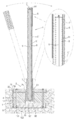
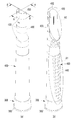
도 3 내지 도 7에 도시된 바와 같이, 시선 유도봉(200)은, 하단부가 노면에 매립 설치되는 것으로, 체결부재(700)가 고정부재(500) 및 가압부재(600)를 통하여 결합단(340)에 체결될 때, 가압 경사면(622)이 밀착 경사면(522)을 가압함에 따라 고정부(520)가 유도봉체(400)의 하단 내주면을 삽입부(320)의 내주면에 가압시켜 고정하도록 된 것이다. 이러한 시선 유도봉(200)은, 노면에 형성된 매립홈(G)에 매립되고, 내측 상부에는 안착단(322)을 구비한 삽입부(320)가 형성되며, 중앙 바닥에는 결합단(340)이 형성된 매립 지지체(300)와, 중공 관형으로 형성되어 하단이 삽입부(320)에 끼워져 안착단(322)에 안착되는 유도봉체(400)와, 내측면에 밀착 경사면(522)을 갖는 고정부(520)가 구비되어 결합단(340)에 안착되는 고정부재(500)와, 가상의 수직선을 기준으로 밀착 경사면(522)보다 더 큰 각도로 경사진 가압 경사면(622)이 외주면에 형성되고, 체결부재(700)에 의해 고정부재(500)와 함께 결합단(340)에 결합되는 가압부재(600)를 포함하여 구성된다. 3 to 7, the
이를 보다 구체적으로 설명한다. This will be described in more detail.
도 3 내지 도 5에 도시된 바와 같이, 매립 지지체(300)는, 노면에 형성된 매립홈(G)에 매립되고, 내측 상부에는 안착단(322)을 구비한 삽입부(320)가 형성되며, 중앙 바닥에는 결합단(340)이 형성된다. 즉 매립 지지체(300)는 바닥이 막힌 원통형으로 이루어져 내측 상부에는 안착단(322)을 구비하고 상향으로 개구된 삽입부(320)가 형성되고, 내측 바닥에는 안착단(322)의 높이와 같은 높이로 결합단(340)이 돌출 형성된 구조를 갖는다. 이때, 결합단(340)의 중앙에는 체결부재(700)가 관통하기 위한 관통공(342)이 형성되고, 노면에 형성되는 매립홈(G)에 매립시 이탈이 방지되도록 삽입부(320)의 외경이 하부로 갈수록 크게 형성되고, 외주면 하단부에는 걸림턱(360)이 형성된다. 이와 같이 외주면 하단 영역에 걸림턱(360)이 환형으로 형성되고 삽입부(320)의 외주면이 걸림턱(360) 쪽으로 갈수록 더 크게 형성됨으로써, 매립홈(G)에 삽입된 상태에서 채움재가 충진되어 경화된 후 외주면과 걸림턱(360)이 걸리게 되어 이탈이 방지될 수 있다.3 to 5, the buried
한편, 안착단(322)과 결합단(340)은 도 5 및 도 6에 도시된 같이 같은 높이로 형성되고, 고정부재(500)가 매립 지지체(300)에 결합될 때 고정부재(500)의 저면 중앙부는 결합단(340)의 상면에 안착되고 저면 가장자리는 안착단(322)의 상면에 안착된다. 이때, 안착단(322)과 결합단(340)이 같은 높이로 형성될 필요는 없으며 결합단(340)이 더 낮게 형성될 수도 있고, 안착단(322)이 더 낮게 형성될 수도 있다. 그러나, 안착단(322)과 결합단(340)이 같은 높이로 형성하여 고정부재(500)가 안정적으로 안착되도록 하는 것이 바람직하다. 이와 같이 고정부재(500)가 안착단(322)와 결합단(340)에 안착되므로 삽입부(320)의 내주면과 고정부재(500)의 고정부(520) 외주면 사이에 유도봉체(400)의 하단부가 끼워지기 위한 끼움홈(S)이 형성된다.Meanwhile, the
이 끼움홈(S)은 가압부재(600)를 가압하는 정도에 따라 좁아지게 되는데 이는 가압부재(500)의 고정부(520)가 가압부재(600)의 가압력에 의해 외측으로 확장되기 때문이고, 이는 고정부재(520)가 유도봉체(400)의 하단부를 더욱 강하게 가압하여 고정함을 의미한다. The fitting groove (S) is narrowed according to the degree of pressing the
이러한 매립 지지체(300)는 경질의 합성수지재 또는 금속재로 이루어질 수 있다. The buried
유도봉체(400)는, 중공 관형으로 형성되어 하단이 삽입부(320)에 끼워져 안착단(322)에 안착되는 것으로, 합성수지재로 형성되고, 외주면에는 반사테이프(450)가 부착된다. 또한, 유도봉체(400)는 구조적 안정성과 직립성 및 자체 강성을 갖도록 원뿔형으로 이루어진다. 즉, 상단부의 직경보다 하단부의 직경이 크게 형성되는 것이다. 이러한 유도봉체(400)는, 도 3에 도시된 바와 같이, 폐합 단면으로 구성될 수도 있고, 도 4의 (a) 및 (b)에 도시된 바와 같이, 비폐합 단면 또는 부분 폐합단면으로 형성될 수 있다. The
본 실시예에서는 유도봉체(400)가 비폐합 단면 또는 부분 폐합단면으로 형성된 것을 기준으로 설명한다. In this embodiment, it will be described based on the
비폐합 단면 또는 부분 폐합 단면으로 된 유도봉체(400)는, 도 4 내지 도 7에 도시된 바와 같이, 유도봉체(400)의 후면의 상부쪽 영역(A2)이 절개되어 외력을 흡수하기 위한 외력 흡수용 개방부(420)가 형성되고, 후면의 중간 및 하부쪽 영역(A1)에는 외력 발생시 용이하게 변형되도록 하기 위한 변형 유도공(440)이 다수개 형성된다. 또한, 상단부가 절개되어 외력 흡수용 개방부(420)와 연결된 상단 개방부(430)가 형성된다. The
이와 같이, 유도봉체(400)의 후면에 외력 흡수용 개방부(420)과 상단 개방부(430) 및 변형 유도공(440)이 형성되어 비폐합 단면 또는 부분 폐합 단면을 갖기 때문에, 유도봉체(400)에 외력이 가해졌을 때 외력을 흡수하면서 변형되므로 파손이 방지되거나 최소화될 수 있다. 즉, 유도봉체(400)의 후면 일부(상부쪽 영역)가 절개되어 외력 흡수용 개방부(420)와 상단 개방부(430)가 형성되어 강성을 갖지 않음으로써, 외력이 가해질 때 변형이 쉽게 이루어질 수 있고, 따라서 외력에 의한 파손이 최소화되거나 방지될 수 있다. 다시 설명하면, 종래기술에 의한 시선 유도봉은 속이 빈 원통형으로 형성되므로 변형이 쉽게 되지 않아 외력이 가해질 때 쉽게 파손되나, 본 발명에 따른 유도봉체(400)는 외력 흡수용 개방부(420)와 상단 개방부(430)가 형성되어 강성을 갖지 않기 때문에 외력이 가해지더라도 쉽게 변형되면서 외력을 흡수하여 파손이 최소화되거나 방지될 수 있는 것이다.As described above, since the
또한, 유도봉체(400)의 후면 하부쪽 영역(A1)에 변형 유도공(440)이 다수개 형성됨으로써, 유도봉체(400)를 전면 쪽에서 후면 방향으로 외력이 가해질 때, 다수개의 변형 유도공(440)이 형성된 후면의 하부쪽 영역(A1)이 변형 유도공(440)들에 의해 쉽게 변형되면서 유도봉체(400)가 후방쪽으로 꺽인다. 즉, 외력이 가해질 때 각 변형 유도공(440)이 형성된 영역이 각 변형 유도공(440) 들에 의해 쉽게 변형되므로 유도봉체(400)가 후방쪽으로 꺽일 수 있다. 따라서 유도봉체(400)는 외력이 가해지더라도 변형될 뿐 파손되지 않게 된다. 그리고 유도봉체(400)의 전방부에는 외력 흡수용 개방부(420)나 변형 유도공(440)이 형성되어 있지 않으므로 외력에 의해 변형된 후 외력이 소멸되면 다시 원상태로 복원될 수 있도록 복원력을 발생시킨다. 이와 같이 외력 흡수용 개방부(420)와 변형 유도공(440)이 후면에만 형성되기 때문에 후방으로의 변형이 쉽게 이루어지고 외력의 소멸시 곧바로 복원된다. 따라서 외력 흡수용 개방부(420)와 변형 유도공(440)이 후면에만 형성되는 구조는 유도봉체(400)의 내구성을 향상시키는 요인이 된다.In addition, a plurality of deformation guide holes 440 are formed in the rear lower region A1 of the
전술한 변형 유도공(440)이 형성된 하부쪽 영역(A1) 및 외력 흡수용 개방부(420)의 형성 위치 및 범위는 유도봉체(400)의 크기 및 형태에 따라 다양하게 구성될 수 있다. The above-described
고정부재(500)는, 가압부재(600)의 가압시 유도봉체(400)의 하단부를 가압하여 매립 지지체(300)에 고정하기 위한 것으로, 도 3에 도시된 바와 같이, 내측면에 밀착 경사면(522)을 갖는 고정부(520)가 환형으로 구비되어 결합단(340)에 안착된다. 이러한 고정부재(500)는, 도 3에 도시된 바와 같이, 중앙에 체결부재(700)가 관통하기 위한 관통공이 형성되고, 가압부재(600)의 가압시 외측으로 변형되도록, 고무재 또는 합성수지재로 이루어진다. The fixing
이러한 고정부재(500)는 도면에 도시되지 않았으나, 금속재로 이루어질 수 있다. 금속재로 이루어지는 경우에, 환형(원통형상)의 고정부(520)에는 상부에서 하향으로 절개부가 형성된다. 이 절개부는 일정한 간격으로 적어도 1개 이상의 수로 형성됨으로써 고정부(520)는 적어도 1개 이상의 가압편으로 이루어질 수 있다. 이러한 구조에 의해 가압부재(600)가 하향으로 이동하면서 가압할 때 각각의 가압편의 각 상단부가 외측으로 변형되면서 유도봉체(400)의 하단부 내측면을 삽입부(320)의 내측면에 가압하여 견고하게 고정할 수 있다. The fixing
가압부재(600)는, 체결부재(700)의 체결력에 의해 하향(결합단 쪽)으로 이동하면서 고정부재(500)의 고정부(520)를 외측으로 가압하여 확장 변형시키기 위한 것으로, 가상의 수직선(L)을 기준으로 밀착 경사면(522)보다 더 큰 각도로 경사진 가압 경사면(622)이 외주면에 형성되고, 체결부재(700)에 의해 고정부재(500)와 함께 결합단(340)에 결합된다. 이러한 가압부재(600)는 금속재 또는 경질의 합성수지재로 이루어지며, 가장자리에 링 형상의 가압단(620)이 상향 바깥쪽으로 비스듬하게 기울어 돌출 형성되고, 이 가압단(620)의 외주면에 가압 경사면(622)이 형성되는 것이다. 이러한 가압단(620)의 가압 경사면(622)은 고정부(520)를 외측으로 밀어 확장 변형시키기 위한 것이다. 이때, 가압부재(600)의 직경이 고정부재(500)의 내경보다 크게 형성됨으로써 가압부재(600)를 체결부재(700)로 체결할 때 하향으로 이동하면서 고정부재(500)를 외측으로 확장되도록 가압할 수 있다. 즉, 가압 경사면(622)이 밀착 경사면(522) 보다 더 크게 형성되지 않아도 가압부재(600)의 직경이 고정부재(500)의 직경보다 크게 형성됨으로써 같은 작용을 기대할 수 있다. The pressing
이와 같이 구성된 시선 유도봉(200)은, 도 7에 도시된 바와 같이 전면 쪽에서 유도봉체(400)에 외력이 가해지면, 후면의 하부영역(A1)이 각 변형 유도공(440)들에 의해 쉽게 변형되므로 파손되지 않고 후방쪽으로 꺽이게 된다. 그러나 유도봉체(400)에 가해지는 외력은 각 변형 유도공(440)이 형성된 하부영역(A1)이 꺽임 변형되면서 흡수하게 되므로 유도봉체(400)의 파손은 일어나지 않는다. 즉, 유도봉체(400)가 외력 흡수용 개방부(420) 및 변형 유도공(440)들에 의해 쉽게 변형됨으로써 외력이 가해지더라도 파손되지 않게 된다. The
체결부재(700)는, 가압부재(600)와 고정부재(500)를 결합단(340)에 결합시켜 유도봉체(400)의 하단부를 고정하기 위한 것으로, 볼트로 이루어져 매립 지지체(300)에 구비되는 너트 또는 체결공에 체결되거나, 너트로 이루어져 매립 지지체(300)에 구비되는 볼트에 체결될 수 있다. The
이와 같이 구성된 시선 유도봉(200)을 시공하는 방법을 도 3 내지 도 7 및 아래 도 8을 토대로 설명하기로 한다. The method of constructing the
첨부된 도면 중에서, 도 8은 (a) 및 (b)는 도 3에 도시된 시선 유도봉의 시공방법을 설명하기 위한 개략적 블럭도 및 유도봉체를 교체하는 방법을 설명하기 위한 개략적 블럭도이다. Among the accompanying drawings, FIGS. 8A and 8B are schematic block diagrams illustrating a method of constructing the gaze guide rod shown in FIG. 3 and schematic block diagrams illustrating a method of replacing the guide rod.
도 3 내지 도 7 및 도 8의 (a)에 도시된 바와 같이, 본 발명에 따른 시선 유도봉(200)을 노면에 매립 시공하기 위한 시공방법은 다음과 같다. 3 to 7 and 8 (a), the construction method for embedding the
(a) 시선 유도봉 조립단계(S1)(a) Gaze guide rod assembly step (S1)
시선 유도봉(200)을 매립 시공하기 위해서는 먼저 시선 유도봉(200)을 조립한다. 즉, 매립 지지체(300)의 삽입부(320)에 유도봉체(400)의 하단을 끼워 안착단(322)에 안착시킨다. 이어서 고정부(520)를 구비한 고정부재(500)를 안착단(322)의 상면에 안착시키며 고정부재(500)의 상면에 가압부재(600)를 안착시킨다. 가압부재(600)가 고정부재(500)의 상면에 안착되면, 체결부재(700)를 가압부재(600)와 고정부재(500)를 통하여 매립 지지체(300)에 구비된 너트에 체결한다. 체결부재(700)를 너트에 체결하게 되면, 가압부재(600)가 고정부재(500)의 하향(결합단 쪽)으로 가압하게 되므로, 고정부(520)가 외측으로 확장 변형되면서 유도봉체(400)의 하단을 삽입부(320)의 내주면에 밀착 고정하게 된다. 이때, 고정부(520)는, 가압부재(600)의 가압 경사면(622)이 밀착 경사면(522)을 가압함에 따라 외측으로 확장 변형되면서 유도봉체(400)의 하단부 내측면을 삽입부(320)의 내측면에 강하게 밀착시켜 유도봉체(400)를 매립 지지체(300)에 결합하게 된다. In order to embed the
이 과정으로 매립 지지체(300), 유도봉체(400), 가압부재(600) 및 고정부재(500)의 조립이 완료되어 일체화 된다. In this process, the assembly of the buried
(b) 매립홈 형성단계(S2)(b) Landfill groove formation step (S2)
전술한 과정으로 시선 유도봉(200)의 조립이 완료되면, 조립이 완료된 시선 유도봉(200)이 설치될 노면에 매립홈(G)을 형성한다. 이 작업은 코어링 작업으로서 노면에 매립 지지체(300)가 삽입될 크기(직경 및 깊이)로 매립홈(G)을 형성하는 것이다. 이때, 매립홈(G)의 깊이는 매립 지지체(300)의 높이보다 더 깊거나 같도록 한다. 이는 매립 지지체(300)가 매립되었을 때 매립 지지체(300)의 삽입부(320)의 상단부가 노면보다 더 돌출되지 않도록 하기 위한 것이다. 만약, 삽입부(320)의 상단부가 노면보다 더 돌출되는 경우에, 차량의 타이어에 손상을 주는 등 차량의 주행에 간섭될 수 있기 때문에, 매립홈(G)의 깊이는 매립 지지체(300)의 높이보다 더 깊거나 같도록 형성하는 것이 바람직하다. When the assembly of the
(c) 채움재 충진단계(S3)(c) Filling material filling step (S3)
전술한 매립홈 형성단계에 의해 노면에 매립홈(G)이 형성되면, 매립홈(G)에 조립이 완료된 시선 유도봉(200)의 매립 지지체(300)를 삽입한다. 즉, 시선 유도봉(200)을 세워서 매립홈(G)에 삽입한다. 이 과정으로 매립 지지체(300)가 매립홈(G)에 세워진 상태로 삽입된다. 이어서, 매립 지지체(300)가 삽입된 매립홈(G)에 채움재를 충진하여 경화하여 시선 유도봉(200)의 시공을 완료한다. 여기서 채움재는 무수축 몰탈을 사용할 수 있으나 이에 국한되는 것은 아니고 다양한 재질이 적용될 수 있음은 물론이다.When the buried groove G is formed on the road surface by the above-described buried groove forming step, the buried
전술한 과정으로 채움재가 경화되면, 매립 지지체(300)의 걸림턱(360)이 경화된 채움재에 걸리게 되므로 매립 지지체(300)가 이탈되지 않게 된다. When the filling material is cured by the above-described process, the engaging
이상에서와 같이, 시선 유도봉(200)을 조립하고 매립홈(G)을 형성하여 매립 지지체(300)를 삽입한 후 채움재를 충진함으로써 시선 유도봉(200) 의 매립 시공이 완료된다. 이때, 매립홈(G)을 먼저 형성하고 시선 유도봉(200)을 조립하는 과정으로 시공을 하여도 무방하다. As described above, assembling the
한편, 시선 유도봉(200)의 시공 완료 후, 시선 유도봉(200)의 파손시 이를 시선 유도봉(200)을 교체하기 위한 방법을 첨부된 도면 중에서, 도 3 내지 도 7 및 도 8의 (b)를 참조하여 설명한다.On the other hand, after the completion of the construction of the
(d) 가압력 해제단계(S4)(d) Pressure release step (S4)
시선 유도봉(200)의 유도봉체(400)가 파손되어 교체해야 할 경우에, 체결부재(700)를 풀어 가압부재(600)의 가압력을 해제한다. 가압부재(600)의 가압력이 해제되면, 고정부(520)가 삽입부(320)에서 이격되므로 잔여 유도봉체(400)가 끼움홈(S)에서 분리될 수 있다. 이 과정으로 잔여 유도봉체(400)가 제거되면, 고정부(520)와 삽입부(320)의 내주면 사이에 끼움홈(S)이 확보된다.When the
(e) 가 조립단계(S5)(e) A Assembly step (S5)
전술한 가압력 해제단계(S4)를 진행하여 끼움홈(S)을 넓게 확보한 후, 새로운 유도봉체(400)의 하단을 고정부(520)와 삽입부(320)의 내주면 사이에 확보된 끼움홈(S)으로 삽입하여 안착단(322)에 안착시킨다. After performing the aforementioned pressing force release step (S4) to secure the fitting groove (S) wide, the lower end of the
f) 교체 완료단계(S6)f) Replacement completion step (S6)
전술한 가 조립단계(S5)에 의해 유도봉체(400)의 하단이 끼움홈(S)에 끼워진 상태에서, 유도봉체(400)의 상단 개방부(430)와 외력 흡수용 개방부(420)를 통하여 체결공구(도시되지 않음)를 유도봉체(400)의 내부로 삽입한다. 이어서 체결공구로 체결부재(700)를 조임 체결하여 가압부재(600)가 고정부(520)를 외측으로 가압하도록 한다. 수직선(L)을 기준으로 고정부(520)의 밀착 경사면(522)의 각도보다 가압 경사면(622)의 각도가 더 크거나, 가압부재(600)가 고정부재(500)보다 더 크게 형성되기 때문에, 체결부재(700)를 체결하여 가압부재(600)를 하향으로 가압하게 되면, 고정부(520)가 외측으로 확장 변형되면서 유도봉체(400)의 하단을 삽입부(320)의 내측면(322)에 견고하게 고정하게 된다.In the state that the lower end of the
이와 같이, 유도봉체(400)의 하단을 끼움홈(S)에 끼운 후 체결부재(700)를 조이는 동작만으로 새로운 유도봉체(400)를 노면에 매립된 매립 지지체(300)에 결합할 수 있게 되어 교체 작업이 완료된다. As such, the
한편, 도 9는 본 발명의 제2 실시예에 따른 시선 유도봉을 도시한 사시도이다. Meanwhile, FIG. 9 is a perspective view showing a gaze guide rod according to a second embodiment of the present invention.
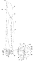
도 9에 도시된 바와 같이, 제2 실시예에 따른 시선 유도봉(200)은, 하단부가 매립 조립체 또는 기초부재(A)에 의해 노면에 설치되는 것으로, 중공 관형으로 형성되어 하단이 기초부재(A)에 결합되는 유도봉체(400)를 포함하고, 유도봉체(400)는, 외력이 가해질 때 외력을 흡수하고 변형을 유도하여 파손을 방지하도록 비폐합 단면 또는 부분 폐합 단면으로 형성되는 것을 제외하고는 전술한 실시예와 같다. As shown in Figure 9, the
즉, 제1 실시예에 따른 시선 유도봉(200)은, 유도봉체(400)가 비폐합 단면 또는 부분 폐합 단면으로 형성된 것이다. That is, in the
여기서 비폐합 단면 또는 부분 폐합 단면이라 함은, 중공 관형의 유도봉체(400) 일부분이 절개부나 구멍에 의해 일부 개방된 구조를 의미한다. Here, a non-closed section or a partially closed section refers to a structure in which a portion of the hollow rod-shaped
보다 구체적으로 설명하면, 유도봉체(400)에 전술한 외력 흡수용 개방부(420)나 변형 유도공(440)이 형성되어 개방된 구조를 갖는 것이다. 이러한 외력 흡수용 개방부(420)나 변형 유도공(440)은 유도봉체(400)의 전면에 형성되거나, 유도봉체(400)의 후면에 형성되거나, 유도봉체(400)의 전면과 후면 모두에 형성될 수 있다. 또한, 외력 흡수용 개방부(420)나 변형 유도공(440)은 유도봉체(400)의 양쪽 측면에만 형성될 수 있고, 유도봉체(400)의 전면, 후면, 양쪽 측면 및 양쪽 측면의 일부에 형성될 수 있다. In more detail, the
이때, 외력 흡수용 개방부(420)나 변형 유도공(440)의 형상, 형성위치 등은 한정되지 않음은 당연하다. 즉, 유도봉체(400)에는 충격을 흡수하고 변형을 유도할 수 있는 구멍들을 형성하거나 절개부를 형성하여 비폐합 단면 또는 부분 폐합 단면을 갖도록 할 수도 있는 것이다. At this time, the shape of the
이와 같이 유도봉체(400)에 외력 흡수용 개방부(420) 또는 변형 유도공(440)을 형성하여 유도봉체(400)가 비폐합 단면 또는 부분 폐합 단면을 갖도록 함으로써 외력에 의한 파손이 최소화될 수 있다. Thus, by forming the
즉, 유도봉체(400)에 외력이 가해지면, 외력 흡수용 개방부(420) 또는 변형 유도공(440)이 가해지는 외력(충격)을 흡수하면서 유도봉체(400)의 변형을 유도하기 때문에 유도봉체(400)는 쉽게 변형된다. 따라서, 비폐합 단면 또는 부분 폐합 단면을 갖는 유도봉체(400)의 파손이 방지되거나 최소화될 수 있다. That is, when an external force is applied to the
특히, 유도봉체(400)의 전면과 후면에 개방부나 변형 유도공이 형성될 경우에 유도봉체(400)는 전면 또는 후면으로부터 가해지는 외력에 대응할 수 있고, 전면과 후면 및 양쪽 측면의 일부에 개방부나 변형 유도공이 형성될 경우에 유도봉체(400)는 전면 및 후변으로부터 가해지는 외력에 대응할 수 있을 뿐만 아니라 측면에서 가해지는 외력에도 대응할 수 있게 된다. Particularly, when an opening or a deformed induction hole is formed on the front and rear surfaces of the
그리고, 이와 같이 비폐합 단면 또는 부분 폐합 단면을 갖는 유도봉체(400)는 전술한 매립 지지체(300), 고정부재(500) 및 가압부재(600)로 이루어진 매립 조립체에 의해 노면의 매립홈(G)에 매립될 수도 있고, 앙카방식의 기초부재(A)에 의해 노면 상에 설치될 수도 있다. 즉, 앙카방식이나 매립방식에 적용할 수 있는 것이다.In addition, the
첨부된 도면 중에서, 도 10은 본 발명의 제3 실시예에 따른 시선 유도봉을 도시한 일부확대 단면도이고, 도 11은 본 발명의 제4 실시예에 따른 시선 유도봉을 도시한 일부확대 단면도이며, 도 12은 도 10 및 도 11에 도시된 시선 유도봉의 사용상태를 도시한 사진이다. Among the accompanying drawings, FIG. 10 is a partially enlarged cross-sectional view showing a gaze guide rod according to a third embodiment of the present invention, and FIG. 11 is a partially enlarged cross-sectional view showing a gaze guide rod according to a fourth embodiment of the present invention , FIG. 12 is a photograph showing a state of use of the gaze guide rods illustrated in FIGS. 10 and 11.
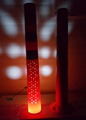
도 10 내지 도 12에 도시된 바와 같이, 매립 지지체(300)나, 가압부재(600) 또는 고정부재(500)에는, 공급되는 전원에 의해 발광되어 유도봉체(400)의 내부를 비춰 야간은 물론 주간에도 시인성을 높이기 위한 발광수단(800)이 마련되는 것을 제외하고는 전술한 실시예와 같다. 10 to 12, the buried
이때, 발광수단(800)은 엘이디(LED)로 이루어지는 것이 바람직하나 이에 국한되는 것은 아니고, 전원은 유도봉체(400) 등에 구비되는 태양광패널과 매립 지지체(300) 등에 구비되는 충전 배터리로 이루어진 자체 태양광발전장치로부터 공급받을 수도 있고, 도 10에 도시된 바와 같이, 가로등으로부터 공급되는 외부전원 또는 도로변에 설치되는 별도의 외부 태양광발전장치로부터 외부전원을 공급받을 수도 있다. 도 10는 발광수단(800)이 외부로부터 전원공급선((810)에 의해 전원이 공급되는 것을 도시하고 있다. At this time, the light emitting means 800 is preferably made of an LED (LED), but is not limited to this, the power source itself is made of a rechargeable battery provided on the solar panel and the buried
그리고 발광수단(800)은, 도 10에 도시된 바와 같이, 가압부재(600)의 상면에 구비되어 발광되는 빛이 유도봉체(400)의 내주면(내부)을 비추도록 할 수도 있고, 도 11에 도시된 바와 같이, 매립 지지체(300)에 구비되어 발광되는 빛이 유도봉체(400)의 외주면(외부)을 비추도록 할 수 있다. 발광수단(800)이 매립 지지체(300)에 구비되는 경우에, 도 11에 도시된 바와 같이, 발광수단(800)이 삽입부(320)의 상단부에 매립되어 설치될 수 있다. 물론, 발광수단(800)은 노면보다 낮은 위치의 매립 조립체에 설치될 수 있다. And the light-emitting
한편, 발광수단(800)은 회로를 내장하여 필요에 따라 점멸 발광되도록 작동될 수도 있다. On the other hand, the light emitting means 800 may be operated so as to emit a flashing light if necessary by a built-in circuit.
그리고 발광수단(800)은 원형으로 이루어질 수 있다. 이는 발광되는 빛이 유도봉체(400)의 내주면 또는 외주면 전체를 균일하게 비추도록 할 수도 있다. In addition, the light emitting means 800 may be formed in a circular shape. This may cause light emitted to uniformly illuminate the entire inner or outer circumferential surface of the
이와 같이, 발광수단(800)이 가압부재(600)의 상면 또는 가압부재(600)를 포함하는 매립 조립체에 구비되어, 노면보다 낮게 위치하거나 같은 높이에 위치하게 됨으로써, 차량의 주행이나 보행자에 의해 발생하는 외력에 의해 파손되지 않게 된다. 따라서, 발광수단(800)의 유지보수 비용이 현저하게 절감될 수 있다. As described above, the light emitting means 800 is provided on the upper surface of the
또한, 발광수단(800)이 매립 지지체(300)의 내부에 구비되기 때문에 유도봉체(400)가 파손되더라도 발광수단(800)은 파손되지 않게 된다. In addition, since the light emitting means 800 is provided inside the buried
한편, 도 12는 발광수단(800)이 적용된 시선 유도봉(200)의 한 예를 도시하고 있다. 도 12에 도시된 바와 같이, 발광수단(800)이 매립 조립체에 구비된 상태에서 전원이 공급되면, 발광수단(800)에서 발광된 빛은 유도봉체(400)의 내주면을 비추게 된다. 따라서, 주황색 또는 황색 계열의 합성수지재로 된 유도봉체(400) 전체가 발광수단(800)의 빛에 의해 밝게 빛나게 되므로 주간은 물론 야간에 운전자나 보행자에게 주의를 줄 수 있는 시인성이 현저하게 향상될 수 있다. 특히 발광수단(800)이 점멸되는 경우에 시인성은 더욱 향상될 수 있다. Meanwhile, FIG. 12 shows an example of the
이상에서와 같이, 시선 유도봉(200)이 단순한 구조로 구성됨으로써, 제작비용이 절감될 뿐만 아니라, 매립 시공이 용이하게 이루어질 수 있고, 교체 작업도 신속하고 용이하게 이루어질 수 있게 된다. 특히, 시선 유도봉(200)의 유도봉체(400)가 비폐합 단면 또는 부분 폐합 단면으로 형성됨으로써, 차량의 충격으로 인하여 외력이 발생하더라도 쉽게 변형되면서 외력을 흡수하게 되므로 파손이 최소화되거나 방지될 수 있다.As described above, since the
앞에서, 본 발명의 특정한 실시예가 설명되고 도시되었지만 본 발명은 기재된 실시예에 한정되는 것이 아니고, 본 발명의 사상 및 범위를 벗어나지 않고 다양하게 수정 및 변형할 수 있음은 이 기술의 분야에서 통상의 지식을 가진 자에게 자명한 일이다. 따라서, 그러한 수정예 또는 변형예들은 본 발명의 기술적 사상이나 관점으로부터 개별적으로 이해되어서는 안되며, 변형된 실시예들은 본 발명의 특허청구범위에 속한다 하여야 할 것이다.In the foregoing, although specific embodiments of the present invention have been described and illustrated, the present invention is not limited to the described embodiments, and it is common knowledge in the art that various modifications and modifications can be made without departing from the spirit and scope of the present invention. It is obvious to those who have it. Therefore, such modifications or variations should not be individually understood from the technical spirit or viewpoint of the present invention, and the modified embodiments should belong to the claims of the present invention.
200 : 시선 유도봉 300 : 매립 지지체
400 : 유도봉체 500 : 고정부재
600 : 가압부재 700 : 체결부재200: gaze guide rod 300: embedded support
400: guide rod 500: fixing member
600: pressing member 700: fastening member
Claims (2)
중공 관형으로 형성되어 하단이 기초부재에 결합되는 유도봉체를 포함하고,
상기 유도봉체는, 외력이 가해질 때 외력을 흡수하고 변형을 유도하여 파손을 방지하도록 비폐합 단면 또는 부분 폐합 단면으로 형성되며,
상기 유도봉체의 전면, 후면, 양쪽 측면 중 어느 한 곳 이상에는, 상부쪽 영역이 절개되어 외력을 흡수하기 위한 외력 흡수용 개방부가 형성되고, 중간 및 하부쪽 영역에는 외력 발생시 용이하게 변형되도록 하기 위한 변형 유도공이 다수개 형성되며,
상기 유도봉체의 상단부에는, 상단이 절개되어 상단 개방부가 형성되는 것을 특징으로 하는,
시선 유도봉.As a gaze guide rod that the lower end is installed on the road surface by a buried assembly or a base member,
It is formed in a hollow tubular shape and includes an induction rod body at which the lower end is coupled to the base member.
The guide rod is formed of a non-closed section or a partially closed section to absorb external force and induce deformation when an external force is applied to prevent damage.
In one or more of the front, rear, and both sides of the guide rod, the upper region is cut to form an opening for absorbing external force to absorb external force, and the intermediate and lower regions are configured to be easily deformed when external force occurs. A number of deformation induction holes are formed,
On the upper end of the guide rod, characterized in that the upper end is cut to form the upper opening,
Gaze guide rod.
a) 매립 지지체의 삽입부에 유도봉체의 하단을 끼워 안착단에 안착시키고 고정부를 구비한 고정부재를 상기 안착단의 상면에 안착시키며 상기 고정부재의 상면에 가압부재를 안착시킨 후, 체결부재를 상기 가압부재와 고정부재를 통하여 상기 매립 지지체에 체결하여 상기 가압부재로 상기 고정부재의 고정부를 외측으로 변형시켜 상기 유도봉체의 하단을 삽입부의 내주면에 밀착 고정시켜 상기 매립 지지체, 상기 유도봉체, 상기 가압부재 및 고정부재를 조립하는 시선 유도봉 조립단계;
b) 조립이 완료된 상기 시선 유도봉이 설치될 노면에 매립홈을 형성하는 매립홈 형성단계; 및
c) 상기 매립홈에 조립이 완료된 상기 시선 유도봉의 상기 매립 지지체를 삽입한 후 채움재를 충진하여 경화하는 채움재 충진단계를 포함하고,
상기 시선 유도봉의 시공 완료 후, 상기 시선 유도봉의 파손시 상기 시선 유도봉을 교체하기 위하여,
상기 체결부재를 풀어 상기 가압부재의 가압력을 해제한 후 잔여 유도봉체를 제거하여 상기 고정부와 상기 삽입부의 내주면 사이에 끼움홈을 확보하는 가압력 해제단계;
새로운 유도봉체의 하단을 상기 고정부와 삽입부의 내주면 사이에 확보된 끼움홈으로 삽입하여 상기 안착단에 안착시키는 가 조립단계; 및
상기 유도봉체의 상단 개방부와 외력 흡수용 개방부를 통하여 체결공구를 상기 유도봉체의 내부로 삽입한 후 상기 체결부재를 체결하여 상기 고정부가 외측으로 변형되면서 상기 유도봉체의 하단을 상기 삽입부에 고정하여 상기 유도봉체의 교체를 완료하는 교체 완료단계를 더 포함하는 것을 특징으로 하는,
시선 유도봉 시공방법.
As a construction method for constructing an eye-guide bar on the road surface,
a) Insert the lower end of the guide rod into the insertion portion of the embedded support, seat it on the seating end, seat the fixing member with the fixing part on the upper surface of the seating end, and seat the pressing member on the upper surface of the fixing member, and then fasten the member. Is fastened to the buried support through the pressing member and the fixing member to deform the fixing part of the fixing member to the outside by the pressing member to securely fix the lower end of the induction rod to the inner circumferential surface of the inserting portion, the buried support, the induction rod , Assembling a gaze guide rod for assembling the pressing member and the fixing member;
b) a buried groove forming step of forming a buried groove on the road surface on which the gaze guide rod is completed to be installed; And
c) a filling material filling step of filling and curing the filling material after inserting the embedded support of the gaze guide rod, which has been assembled into the filling groove,
In order to replace the gaze guide rod when the gaze guide rod is damaged after the construction of the gaze guide rod is completed,
A pressing force release step of releasing the fastening member to release the pressing force of the pressing member and then removing the remaining guide rod to secure a fitting groove between the fixing part and the inner peripheral surface of the inserting part;
An assembly step of inserting the lower end of the new guide rod into the fitting groove secured between the fixing part and the inner circumferential surface of the inserting part to seat the seating end; And
After inserting a fastening tool into the inside of the guide rod through the upper opening portion of the guide rod and the opening portion for absorbing external force, the fastening member is fastened to the outside and the lower end of the guide rod is fixed to the insert portion It characterized in that it further comprises a replacement completion step of completing the replacement of the guide rod,
Construction method of gaze guide rod.
Priority Applications (1)
| Application Number | Priority Date | Filing Date | Title |
|---|---|---|---|
| KR1020200086942A KR20200089251A (en) | 2020-07-14 | 2020-07-14 | Delineator post and construction method therof |
Applications Claiming Priority (1)
| Application Number | Priority Date | Filing Date | Title |
|---|---|---|---|
| KR1020200086942A KR20200089251A (en) | 2020-07-14 | 2020-07-14 | Delineator post and construction method therof |
Related Parent Applications (1)
| Application Number | Title | Priority Date | Filing Date |
|---|---|---|---|
| KR1020180113648A Division KR102214487B1 (en) | 2018-09-21 | 2018-09-21 | Delineator post and construction method therof |
Publications (1)
| Publication Number | Publication Date |
|---|---|
| KR20200089251A true KR20200089251A (en) | 2020-07-24 |
Family
ID=71892570
Family Applications (1)
| Application Number | Title | Priority Date | Filing Date |
|---|---|---|---|
| KR1020200086942A KR20200089251A (en) | 2020-07-14 | 2020-07-14 | Delineator post and construction method therof |
Country Status (1)
| Country | Link |
|---|---|
| KR (1) | KR20200089251A (en) |
Citations (2)
| Publication number | Priority date | Publication date | Assignee | Title |
|---|---|---|---|---|
| KR101178229B1 (en) | 2011-11-23 | 2012-08-29 | (주)로드스톤 | Lane delineator |
| KR20170079186A (en) | 2015-12-30 | 2017-07-10 | 벤토글로벌(주) | Glance guide bar |
-
2020
- 2020-07-14 KR KR1020200086942A patent/KR20200089251A/en not_active Application Discontinuation
Patent Citations (2)
| Publication number | Priority date | Publication date | Assignee | Title |
|---|---|---|---|---|
| KR101178229B1 (en) | 2011-11-23 | 2012-08-29 | (주)로드스톤 | Lane delineator |
| KR20170079186A (en) | 2015-12-30 | 2017-07-10 | 벤토글로벌(주) | Glance guide bar |
Similar Documents
| Publication | Publication Date | Title |
|---|---|---|
| KR101671492B1 (en) | Delineator post | |
| KR200394955Y1 (en) | Bollard which Safety and construction be improved | |
| WO2005113897A1 (en) | A road line safety pillar | |
| US11466414B2 (en) | Traffic control marker including a reinforcing member | |
| KR20120063637A (en) | Safety bar easy to assemble and seperate | |
| KR102214487B1 (en) | Delineator post and construction method therof | |
| KR20200089251A (en) | Delineator post and construction method therof | |
| GB2125863A (en) | Supporting road signs | |
| KR100810574B1 (en) | Stick Induced in Glance | |
| JPH08239812A (en) | Traffic sign post | |
| JP2007126933A (en) | Bumping post | |
| KR20160057272A (en) | In the event of a traffic accident, it is designed to minimize the casualties caused by human accidents, which are combined with facilities for safety of traffic accidents including street light landing pillar, road sign pillar, interrupted camera pillar, traffic signal pillar, electric power pole, Prevention of joints | |
| KR102282598B1 (en) | Multifunctional Transportation Guidance Facility | |
| KR102243192B1 (en) | Non-volt landfill lane regulatory rod | |
| KR200373191Y1 (en) | Separation type street light | |
| KR200337550Y1 (en) | A steet lamp floor cover unit within base | |
| KR102168269B1 (en) | Multipurpose attention pole | |
| KR200394458Y1 (en) | Lane indicator | |
| KR100657561B1 (en) | The member for preventing the breakaway of the vechicle | |
| KR20080093753A (en) | A protecting device for street light and traffic light | |
| KR200297991Y1 (en) | Center-line separated lane control bar with integrated center line and reflective indicator | |
| KR200149321Y1 (en) | Traffic lane control stick | |
| KR101631239B1 (en) | piston type road safety reflector | |
| JP5341692B2 (en) | Road marking object | |
| KR102645037B1 (en) | Traffic line seperator that can adjust the installation height and can be easily replaced |
Legal Events
| Date | Code | Title | Description |
|---|---|---|---|
| A107 | Divisional application of patent | ||
| E902 | Notification of reason for refusal | ||
| E601 | Decision to refuse application |